Embed Size (px)
Citation preview

Updated: 29/0/20081
CCNA Exploration
Network Fundamentals
Chapter 08
OSI Physical Layer

2
8.0.1 Introduction
Upper OSI layer protocols prepare data from the human network for transmission
to its destination.
The Physical layer controls how data is placed on the communication media.
The role of the OSI Physical layer is to encode the binary digits that represent
Data Link layer frames into signals and to transmit and receive these signals
across the physical media - copper wires, optical fiber, and wireless - that
connect network devices.

3
8.1 The Physical Layer – Communicating Signals
8.1.1 Physical Layer - Purpose
4
8.1.1 Physical Layer - Purpose The OSI Physical layer provides the means to transport across the network
media the bits that make up a Data Link layer frame.
This layer accepts a complete frame from the Data Link layer and encodes it
as a series of signals that are transmitted onto the local media. The encoded
bits that comprise a frame are received by either an end device or an
intermediate device.
The delivery of frames across the local media requires the following Physical
layer elements:
The physical media and associated connectors
A representation of bits on the media
Encoding of data and control information
Transmitter and receiver circuitry on the network devices
The purpose of the Physical layer is to create the electrical, optical, or
microwave signal that represents the bits in each frame.
These signals are then sent on the media one at a time.
It is also the job of the Physical layer to retrieve these individual signals from
the media, restore them to their bit representations, and pass the bits up to the
Data Link layer as a complete frame.

5
8.1.2 Physical Layer - Operation

6
8.1.2 Physical Layer - Operation
The media does not carry the frame as a single entity. The media carries
signals, one at a time, to represent the bits that make up the frame.
There are three basic forms of network media on which data is represented:
Copper cable, Fiber, Wireless
The representation of the bits (type of signal) depends on the type of media.
For copper cable media, the signals are patterns of electrical pulses.
For fiber, the signals are patterns of light.
For wireless media, the signals are patterns of radio transmissions.
Identifying a Frame
When the Physical layer encodes the bits into the signals for a particular
medium, it must also distinguish where one frame ends and the next frame
begins. Otherwise, the devices on the media would not recognize when a
frame has been fully received.
To enable a receiving device to clearly recognize a frame boundary, the
transmitting device adds signals to designate the start and end of a frame.
These signals represent particular bit patterns that are only used to denote the
start or end of a frame.
7
8.1.3 Physical Layer – Standards
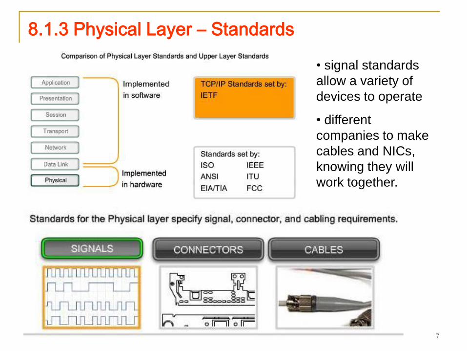
• signal standards
allow a variety of
devices to operate
• different
companies to make
cables and NICs,
knowing they will
work together.

8
8.1.3 Physical Layer – Standards
The Physical layer consists of hardware, developed by engineers, in the
form of electronic circuitry, media, and connectors. The standards
governing this hardware are defined by the relevant electrical and
communications engineering organizations.
By comparison, the protocols and operations of the upper OSI layers are
performed by software and are designed by software engineers and
computer scientists. The services and protocols in the TCP/IP suite are
defined by the Internet Engineering Task Force (IETF) in RFCs.
Similar to technologies associated with the Data Link layer, the Physical
layer technologies are defined by organizations such as:
The International Organization for Standardization (ISO)
The Institute of Electrical and Electronics Engineers (IEEE)
The American National Standards Institute (ANSI)
The International Telecommunication Union (ITU)
The Electronics Industry Alliance/Telecommunications Industry
Association (EIA/TIA)
National telecommunications authorities such as the Federal
Communication Commission (FCC) in the USA.
9
8.1.3 Physical Layer – Standards
Physical Layer Technologies and Hardware
The technologies defined by these organizations include
four areas of the Physical layer standards:
Physical and electrical properties of the media
Mechanical properties (materials, dimensions,
pinouts) of the connectors
Bit representation by the signals (encoding)
Definition of control information signals
Hardware components such as network adapters (NICs),
interfaces and connectors, cable materials, and cable
designs are all specified in standards associated with the
Physical layer.
10
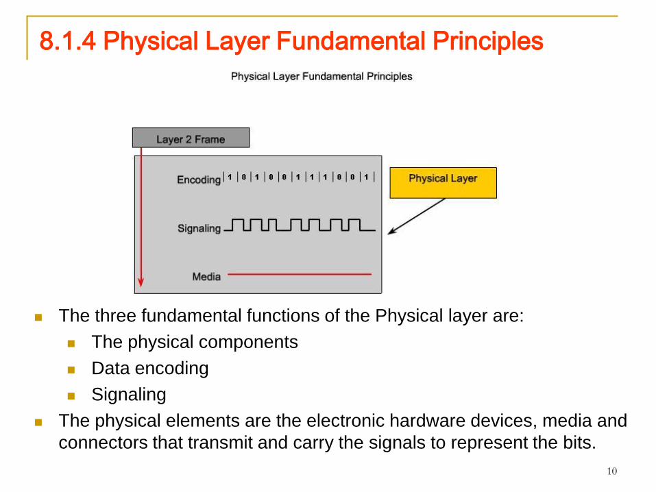
8.1.4 Physical Layer Fundamental Principles
The three fundamental functions of the Physical layer are:
The physical components
Data encoding
Signaling
The physical elements are the electronic hardware devices, media and
connectors that transmit and carry the signals to represent the bits.

11
8.1.4 Physical Layer Fundamental PrinciplesEncoding
Encoding is a method of converting a stream of data bits into a
predefined code. Codes are groupings of bits used to provide a
predictable pattern that can be recognized by both the sender and the
received. Using predictable patterns helps to distinguish data bits from
control bits and provide better media error detection.
Encoding methods at the Physical layer may also provide codes for
control purposes such as identifying the beginning and end of a frame.
The transmitting host will transmit the specific pattern of bits or a code
to identify the beginning and end of the frame.
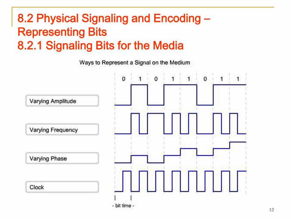
Signaling
The Physical layer must generate the electrical, optical, or wireless
signals that represent the "1" and "0" on the media.
The method of representing the bits is called the signaling method. The
Physical layer standards must define what type of signal represents a
"1" and a "0".
This can be as simple as a change in the level of an electrical signal or
optical pulse or a more complex signaling method.
12
8.2 Physical Signaling and Encoding –
Representing Bits
8.2.1 Signaling Bits for the Media

13
8.2.1 Signaling Bits for the Media

14
8.2.1 Signaling Bits for the Media
15
8.2.3 Data Carrying Capacity
16
8.2.3 Data Carrying Capacity
17
8.2.3 Data Carrying Capacity
Different physical media support the transfer of bits at different
speeds.
Data transfer can be measured in three ways:
Bandwidth
Throughput
Goodput
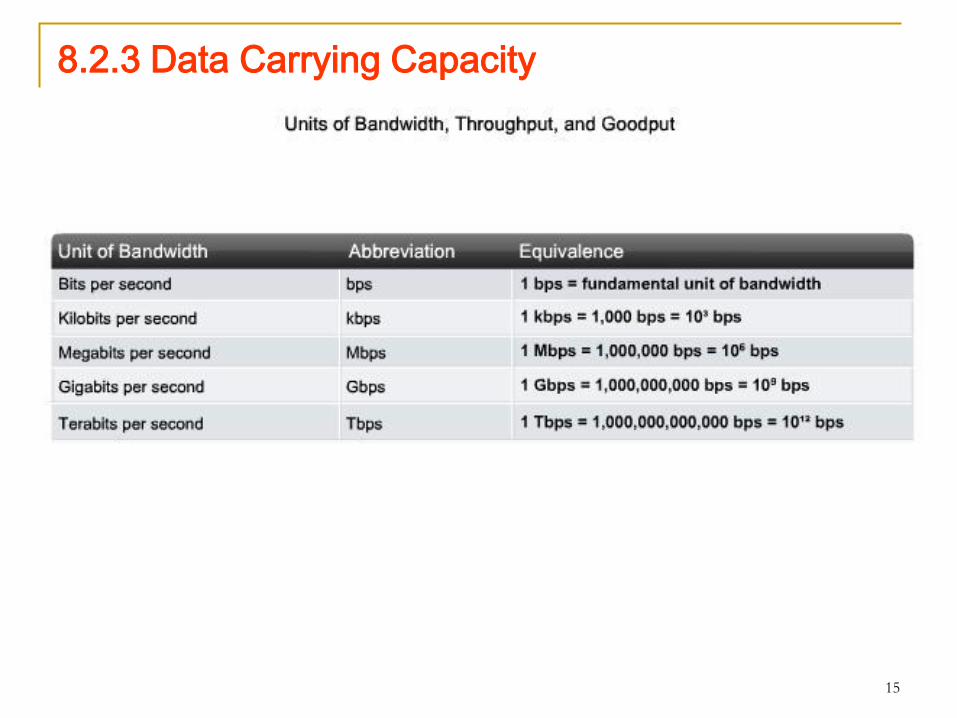
Bandwidth
The capacity of a medium to carry data is described as the raw data
bandwidth of the media. Digital bandwidth measures the amount of
information that can flow from one place to another in a given amount
of time. Bandwidth is typically measured in kilobits per second (kbps)
or megabits per second (Mbps).
The practical bandwidth of a network is determined by a combination
of factors: the properties of the physical media and the technologies
chosen for signaling and detecting network signals.
Physical media properties, current technologies, and the laws of
physics all play a role in determining available bandwidth.
18
8.2.3 Data Carrying Capacity
Throughput
Throughput is the measure of the transfer of bits across the media
over a given period of time. Throughput usually does not match the
specified bandwidth in Physical layer implementations such as
Ethernet.
Many factors influence throughput. Among these factors are the
amount of traffic, the type of traffic, and the number of network devices
encountered on the network being measured. In a multi-access
topology such as Ethernet, nodes are competing for media access and
its use. Therefore, the throughput of each node is degraded as usage
of the media increases.
In an internetwork or network with multiple segments, throughput
cannot be faster than the slowest link of the path from source to
destination. Even if all or most of the segments have high bandwidth, it
will only take one segment in the path with low throughput to create a
bottleneck to the throughput of the entire network.

19
8.2.3 Data Carrying Capacity
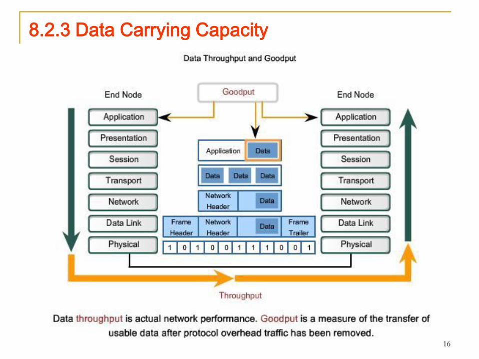
Goodput
A third measurement has been created to measure the transfer
of usable data. That measure is known as goodput.
Goodput is the measure of usable data transferred over a given
period of time, and is therefore the measure that is of most
interest to network users.
Goodput measures the effective transfer of user data between
Application layer entities, such as between a source web server
process and a destination web browser device.
Unlike throughput, which measures the transfer of bits and not
the transfer of usable data, goodput accounts for bits devoted to
protocol overhead.
Goodput is throughput minus traffic overhead for establishing
sessions, acknowledgements, and encapsulation.
20
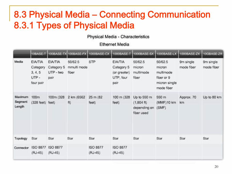
8.3 Physical Media – Connecting Communication
8.3.1 Types of Physical Media

21
8.3.1 Types of Physical Media

22
8.3.1 Types of Physical Media
The Physical layer is concerned with network media and signaling.
This layer produces the representation and groupings of bits as
voltages, radio frequencies, or light pulses.
Various standards organizations have contributed to the definition of
the physical, electrical, and mechanical properties of the media
available for different data communications.
These specifications guarantee that cables and connectors will
function as anticipated with different Data Link layer
implementations.
Standards for copper media are defined for the:
Type of copper cabling used
Bandwidth of the communication
Type of connectors used
Pinout and color codes of connections to the media
Maximum distance of the media
23
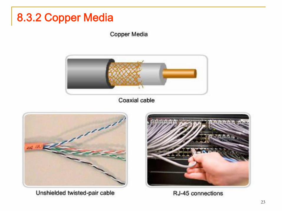
8.3.2 Copper Media

24
8.3.2 Copper Media
25
8.3.2 Copper Media
The most commonly used media for data communications is cabling
that uses copper wires to signal data and control bits between network
devices. Cabling used for data communications usually consists of a
series of individual copper wires that form circuits dedicated to specific
signaling purposes.
Other types of copper cabling, known as coaxial cable, have a single
conductor that runs through the center of the cable that is encased by,
but insulated from, the other shield. The copper media type chosen is
specified by the Physical layer standard required to link the Data Link
layers of two or more network devices.
These cables can be used to connect nodes on a LAN to intermediate
devices, such as routers and switches. Cables are also used to
connect WAN devices to a data services provider such as a telephone
company. Each type of connection and the accompanying devices
have cabling requirements stipulated by Physical layer standards.
Networking media generally make use of modular jacks and plugs,
which provide easy connection and disconnection. Also, a single type
of physical connector may be used for multiple types of connections.
26
8.3.2 Copper Media
External Signal Interference
Data is transmitted on copper cables as electrical pulses.
A detector in the network interface of a destination device
must receive a signal that can be successfully decoded to
match the signal sent.
The timing and voltage values of these signals are
susceptible to interference or "noise" from outside the
communications system.
These unwanted signals can distort and corrupt the data
signals being carried by copper media.
Radio waves and electromagnetic devices such as
fluorescent lights, electric motors, and other devices are
potential sources of noise.

27
8.3.2 Copper Media
Cable types with shielding or twisting of the pairs of wires
are designed to minimize signal degradation due to
electronic noise.
The susceptibility of copper cables to electronic noise can
also be limited by:
Selecting the cable type or category most suited to
protect the data signals in a given networking
environment
Designing a cable infrastructure to avoid known and
potential sources of interference in the building
structure
Using cabling techniques that include the proper
handling and termination of the cables
28
8.3.3 Unshielded Twisted Pair (UTP) Cable
29
8.3.3 Unshielded Twisted Pair (UTP) Cable
30
8.3.3 Unshielded Twisted Pair (UTP) Cable
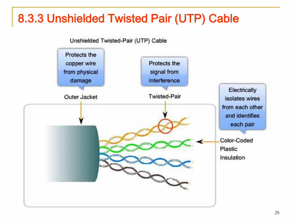
Unshielded twisted-pair (UTP) cabling, as it is used in Ethernet
LANs, consists of four pairs of color-coded wires that have been
twisted together and then encased in a flexible plastic sheath.
The color codes identify the individual pairs and wires in the pairs
and aid in cable termination.
The twisting has the effect of canceling unwanted signals.
When two wires in an electrical circuit are placed close together,
external electromagnetic fields create the same interference in each
wire.
The pairs are twisted to keep the wires in as close proximity as is
physically possible. When this common interference is present on
the wires in a twisted pair, the receiver processes it in equal yet
opposite ways.
As a result, the signals caused by electromagnetic interference from
external sources are effectively cancelled.
31
8.3.3 Unshielded Twisted Pair (UTP) Cable
This cancellation effect also helps avoid interference
from internal sources called crosstalk.
Crosstalk is the interference caused by the magnetic
field around the adjacent pairs of wires in the cable.
When electrical current flows through a wire, it creates a
circular magnetic field around the wire.
With the current flowing in opposite directions in the two
wires in a pair, the magnetic fields - as equal but
opposite forces - have a cancellation effect on each
other.
Additionally, the different pairs of wires that are twisted in
the cable use a different number of twists per meter to
help protect the cable from crosstalk between pairs.
32
8.3.3 Unshielded Twisted Pair (UTP) Cable
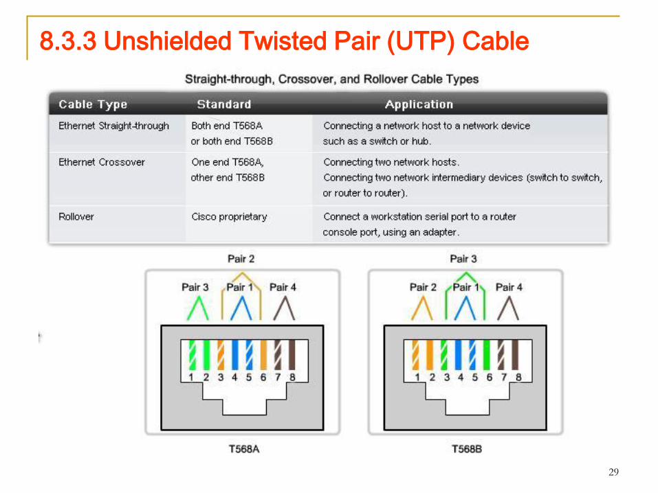
UTP Cable Types
UTP cabling, terminated with RJ-45 connectors, is a common
copper-based medium for interconnecting network devices, such as
computers, with intermediate devices, such as routers and network
switches.
The main cable types obtained by using specific wiring conventions:
Ethernet Straight-through
Ethernet Crossover
Rollover
Using a crossover or straight-through cable incorrectly between
devices may not damage the devices, but connectivity and
communication between the devices will not take place.
This is a common error in the lab and checking that the device
connections are correct should be the first troubleshooting action if
connectivity is not achieved.
33
8.3.4 Other Copper Cable: Coaxial
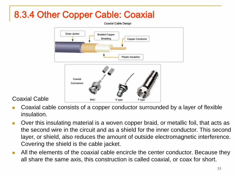
Coaxial Cable
Coaxial cable consists of a copper conductor surrounded by a layer of flexible
insulation.
Over this insulating material is a woven copper braid, or metallic foil, that acts as
the second wire in the circuit and as a shield for the inner conductor. This second
layer, or shield, also reduces the amount of outside electromagnetic interference.
Covering the shield is the cable jacket.
All the elements of the coaxial cable encircle the center conductor. Because they
all share the same axis, this construction is called coaxial, or coax for short.

34
8.3.4 Other Copper CableUses of Coaxial Cable
The coaxial cable design has been adapted for different purposes. Coax is an
important type of cable that is used in wireless and cable access technologies.
Coax cables are used to attach antennas to wireless devices. The coaxial cable
carries radio frequency (RF) energy between the antennas and the radio
equipment.
Coax is also the most widely used media for transporting high radio frequency
signals over wire, especially cable television signals.
Traditional cable television, exclusively transmitting in one direction, was
composed completely of coax cable.
Cable service providers are currently converting their one-way systems to two-
way systems to provide Internet connectivity to their customers. To provide these
services, portions of the coaxial cable and supporting amplification elements are
replaced with multi-fiber-optic cable. However, the final connection to the
customer's location and the wiring inside the customer's premises is still coax
cable. This combined use of fiber and coax is referred to as hybrid fiber coax
(HFC).
In the past, coaxial cable was used in Ethernet installations. Today UTP offers
lower costs and higher bandwidth than coaxial and has replaced it as the
standard for all Ethernet installations.
35
8.3.4 Other Copper Cable
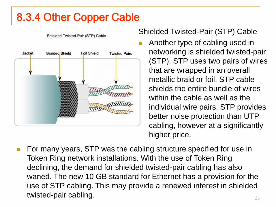
Shielded Twisted-Pair (STP) Cable
Another type of cabling used in
networking is shielded twisted-pair
(STP). STP uses two pairs of wires
that are wrapped in an overall
metallic braid or foil. STP cable
shields the entire bundle of wires
within the cable as well as the
individual wire pairs. STP provides
better noise protection than UTP
cabling, however at a significantly
higher price.
For many years, STP was the cabling structure specified for use in
Token Ring network installations. With the use of Token Ring
declining, the demand for shielded twisted-pair cabling has also
waned. The new 10 GB standard for Ethernet has a provision for the
use of STP cabling. This may provide a renewed interest in shielded
twisted-pair cabling.

36
8.3.5 Copper Media Safety
37
8.3.5 Copper Media SafetyElectrical Hazards
A potential problem with copper media is that the copper wires could conduct
electricity in undesirable ways. This could subject personnel and equipment to a
range of electrical hazards.
A defective network device could conduct currents to the chassis of other network
devices. Additionally, network cabling could present undesirable voltage levels
when used to connect devices that have power sources with different ground
potentials. Such situations are possible when copper cabling is used to connect
networks in different buildings or on different floors of buildings that use different
power facilities. Finally, copper cabling may conduct voltages caused by lightning
strikes to network devices.
The result of undesirable voltages and currents can include damage to network
devices and connected computers, or injury to personnel. It is important that
copper cabling be installed appropriately, and according to the relevant
specifications and building codes, in order to avoid potentially dangerous and
damaging situations.
Fire Hazards
Cable insulation and sheaths may be flammable or produce toxic fumes when
heated or burned. Building authorities or organizations may stipulate related
safety standards for cabling and hardware installations.

38
8.3.6 Fiber Media

39
8.3.6 Fiber Media

40
8.3.6 Fiber Media
Fiber-optic cabling uses either glass or plastic fibers to guide
light impulses from source to destination. The bits are
encoded on the fiber as light impulses. Optical fiber cabling is
capable of very large raw data bandwidth rates. Most current
transmission standards have yet to approach the potential
bandwidth of this media.
Fiber Compared to Copper Cabling
Given that the fibers used in fiber-optic media are not
electrical conductors, the media is immune to electromagnetic
interference and will not conduct unwanted electrical currents
due to grounding issues. Because optical fibers are thin and
have relatively low signal loss, they can be operated at much
greater lengths than copper media, without the need for signal
regeneration. Some optical fiber Physical layer specifications
allow lengths that can reach multiple kilometers.
41
8.3.6 Fiber Media Optical fiber media implementation issues include:
More expensive (usually) than copper media over the same distance (but for
a higher capacity)
Different skills and equipment required to terminate and splice the cable
infrastructure
More careful handling than copper media
At present, in most enterprise environments, optical fiber is primarily used as
backbone cabling for high-traffic point-to-point connections between data
distribution facilities and for the interconnection of buildings in multi-building
campuses. Because optical fiber does not conduct electricity and has low signal
loss, it is well suited for these uses.
Cable Construction
Optical fiber cables consist of a PVC jacket and a series of strengthening
materials that surround the optical fiber and its cladding. The cladding surrounds
the actual glass or plastic fiber and is designed to prevent light loss from the fiber.
Because light can only travel in one direction over optical fiber, two fibers are
required to support full duplex operation. Fiber-optic patch cables bundle together
two optical fiber cables and terminate them with a pair of standard single fiber
connectors. Some fiber connectors accept both the transmitting and receiving
fibers in a single connector.
42
8.3.6 Fiber Media
Generating and Detecting the Optical Signal
Either lasers or light emitting diodes (LEDs) generate the
light pulses that are used to represent the transmitted
data as bits on the media. Electronic semi-conductor
devices called photodiodes detect the light pulses and
convert them to voltages that can then be reconstructed
into data frames.
Note: The laser light transmitted over fiber-optic cabling
can damage the human eye. Care must be taken to avoid
looking into the end of an active optical fiber.
Single-mode and Multimode Fiber
Fiber optic cables can be broadly classified into two types:
single-mode and multimode.

43
8.3.6 Fiber Media
Single-mode optical fiber carries a single ray of light, usually
emitted from a laser. Because the laser light is uni-directional
and travels down the center of the fiber, this type of fiber can
transmit optical pulses for very long distances.
Multimode fiber typically uses LED emitters that do not create a
single coherent light wave. Instead, light from an LED enters
the multimode fiber at different angles. Because light entering
the fiber at different angles takes different amounts of time to
travel down the fiber, long fiber runs may result in the pulses
becoming blurred on reception at the receiving end. This effect,
known as modal dispersion, limits the length of multimode fiber
segments.
Multimode fiber, and the LED light source used with it, are
cheaper than single-mode fiber and its laser-based emitter
technology.
44
8.3.7 Wireless Media
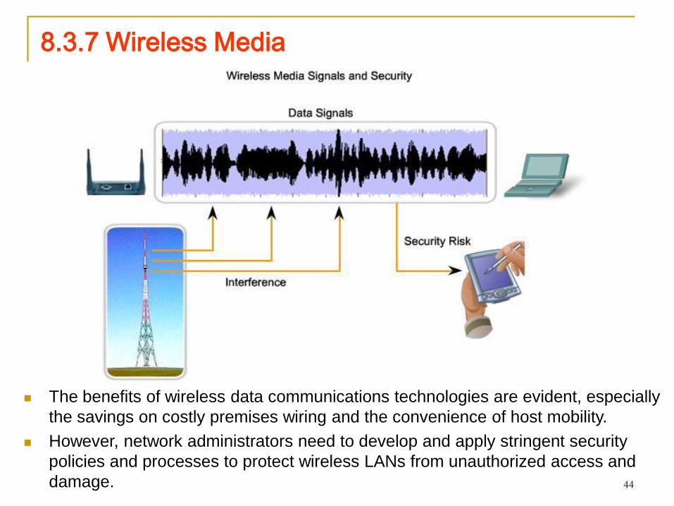
The benefits of wireless data communications technologies are evident, especially
the savings on costly premises wiring and the convenience of host mobility.
However, network administrators need to develop and apply stringent security
policies and processes to protect wireless LANs from unauthorized access and
damage.

45
8.3.7 Wireless Media
Wireless media carry electromagnetic signals at radio and
microwave frequencies that represent the binary digits of data
communications. As a networking medium, wireless is not restricted
to conductors or pathways, as are copper and fiber media.
Wireless data communication technologies work well in open
environments. However, certain construction materials used in
buildings and structures, and the local terrain, will limit the effective
coverage. In addition, wireless is susceptible to interference and can
be disrupted by such common devices as household cordless
phones, some types of fluorescent lights, microwave ovens, and
other wireless communications.
Further, because wireless communication coverage requires no
access to a physical strand of media, devices and users who are not
authorized for access to the network can gain access to the
transmission. Therefore, network security is a major component of
wireless network administration.
46
8.3.7 Wireless Media
Types of Wireless Networks
The IEEE and telecommunications industry standards for wireless
data communications cover both the Data Link and Physical layers.
Four common data communications standards that apply to wireless
media are:
Standard IEEE 802.11 - Commonly referred to as Wi-Fi, is a
Wireless LAN (WLAN) technology that uses a contention or non-
deterministic system with a Carrier Sense Multiple
Access/Collision Avoidance (CSMA/CA) media access process.
Standard IEEE 802.15 - Wireless Personal Area Network
(WPAN) standard, commonly known as "Bluetooth", uses a
device pairing process to communicate over distances from 1 to
100 meters.
Standard IEEE 802.16 - Commonly known as WiMAX
(Worldwide Interoperability for Microwave Access), uses a point-
to-multipoint topology to provide wireless broadband access.
47
8.3.7 Wireless Media
Global System for Mobile Communications (GSM) - Includes
Physical layer specifications that enable the implementation of
the Layer 2 General Packet Radio Service (GPRS) protocol to
provide data transfer over mobile cellular telephony networks.
Other wireless technologies such as satellite communications
provide data network connectivity for locations without another
means of connection. Protocols including GPRS enable data to be
transferred between earth stations and satellite links.
In each of the above examples, Physical layer specifications are
applied to areas that include: data to radio signal encoding,
frequency and power of transmission, signal reception and decoding
requirements, and antenna design and construction.
48
8.3.7 Wireless Media
The Wireless LAN
A common wireless data implementation is enabling
devices to wirelessly connect via a LAN. In general, a
wireless LAN requires the following network devices:
Wireless Access Point (AP) - Concentrates the wireless
signals from users and connects, usually through a
copper cable, to the existing copper-based network
infrastructure such as Ethernet.
Wireless NIC adapters - Provides wireless communication
capability to each network host.
As the technology has developed, a number of WLAN
Ethernet-based standards have emerged. Care needs to
be taken in purchasing wireless devices to ensure
compatibility and interoperability.

49
8.3.7 Wireless Media Standards include:
IEEE 802.11a - Operates in the 5 GHz frequency band and offers
speeds of up to 54 Mbps. Because this standard operates at higher
frequencies, it has a smaller coverage area and is less effective at
penetrating building structures. Devices operating under this standard
are not interoperable with the 802.11b and 802.11g standards
described below.
IEEE 802.11b - Operates in the 2.4 GHz frequency band and offers
speeds of up to 11 Mbps. Devices implementing this standard have a
longer range and are better able to penetrate building structures than
devices based on 802.11a.
IEEE 802.11g - Operates in the 2.4 GHz frequency band and offers
speeds of up to 54 Mbps. Devices implementing this standard
therefore operate at the same radio frequency and range as 802.11b
but with the bandwidth of 802.11a.
IEEE 802.11n - The IEEE 802.11n standard is currently in draft form.
The proposed standard defines frequency of 2.4 Ghz or 5 GHz. The
typical expected data rates are 100 Mbps to 210 Mbps with a distance
range of up to 70 meters.
50
8.3.8 Media Connectors
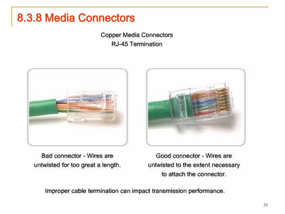
51
8.3.8 Media Connectors

52
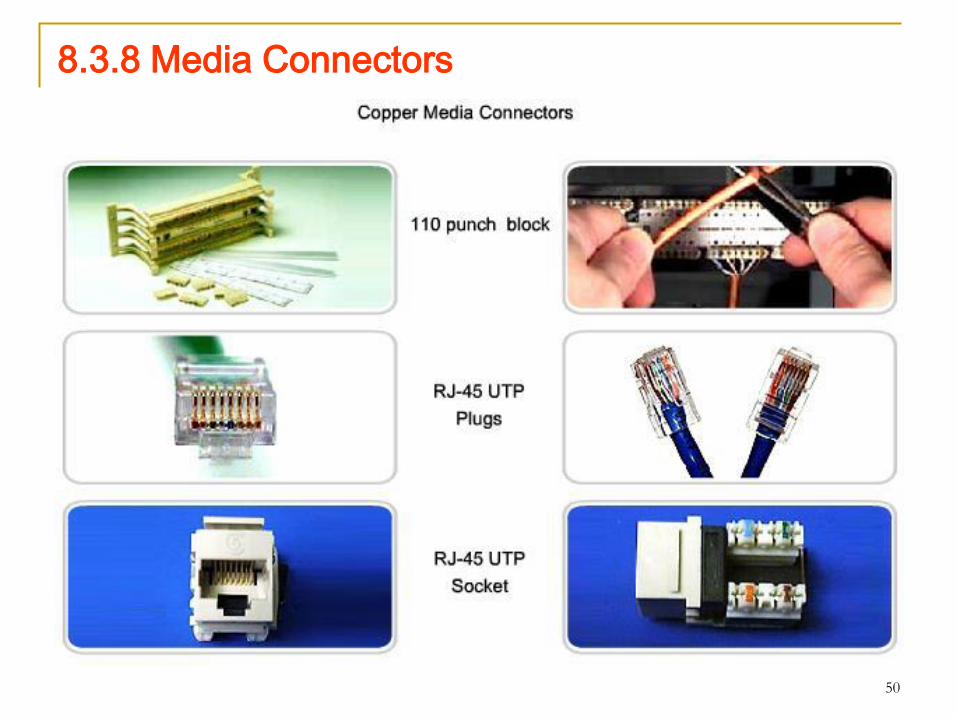
8.3.8 Media Connectors
53
8.3.8 Media Connectors
Common Optical Fiber Connectors
Terminating and splicing fiber-optic cabling requires special training and
equipment. Incorrect termination of fiber optic media will result in
diminished signaling distances or complete transmission failure.
It is recommended that an Optical Time Domain Reflectometer (OTDR)
be used to test each fiber-optic cable segment.
This device injects a test pulse of light into the cable and measures
back scatter and reflection of light detected as a function of time.
The OTDR will calculate the approximate distance at which these faults
are detected along the length of the cable.
A field test can be performed by shining a bright flashlight into one end
of the fiber while observing the other end of the fiber. (Warning: Look
at the correct other end of the cable and not from one whose
source is a laser – will damage eyes!)
If light is visible, then the fiber is capable of passing light.
Although this does not ensure the performance of the fiber, it is a quick
and inexpensive way to find a broken fiber.