Embed Size (px)
Citation preview
96 www.yg1.kr 97www.yg1.kr
Designation GradeDimensions
I D s r
CCMT 120408-UG YG801 11.88 12.70 4.76 0.8
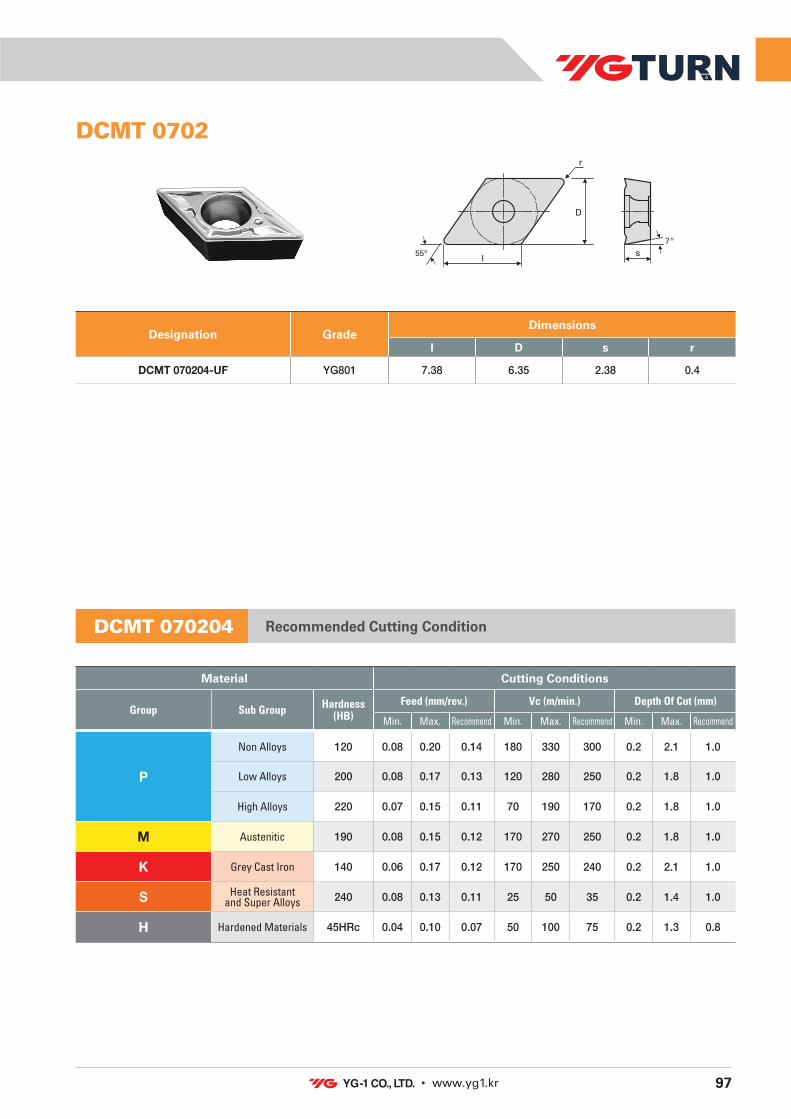
Designation GradeDimensions
I D s r
DCMT 070204-UF YG801 7.38 6.35 2.38 0.4
CCMT 1204 DCMT 0702
Material Cutting Conditions
Group Sub Group Hardness(HB)
Feed (mm/rev.) Vc (m/min.) Depth Of Cut (mm)
Min. Max. Recommend Min. Max. Recommend Min. Max. Recommend
P
Non Alloys 120 0.21 0.50 0.36 180 330 255 0.5 5.0 3.0
Low Alloys 200 0.21 0.45 0.33 120 280 200 0.5 5.0 3.0
High Alloys 220 0.18 0.40 0.29 70 190 130 0.5 4.0 2.5
M Austenitic 190 0.20 0.40 0.30 170 270 200 0.5 5.0 3.0
K Grey Cast Iron 140 0.15 0.60 0.38 170 250 210 0.5 5.0 3.0
S Heat Resistantand Super Alloys 240 0.20 0.35 0.28 25 45 35 0.5 3.0 2.0
H Hardened Materials 45HRc 0.11 0.30 0.21 50 100 75 0.5 2.5 2.0
Material Cutting Conditions
Group Sub Group Hardness(HB)
Feed (mm/rev.) Vc (m/min.) Depth Of Cut (mm)
Min. Max. Recommend Min. Max. Recommend Min. Max. Recommend
P
Non Alloys 120 0.08 0.20 0.14 180 330 300 0.2 2.1 1.0
Low Alloys 200 0.08 0.17 0.13 120 280 250 0.2 1.8 1.0
High Alloys 220 0.07 0.15 0.11 70 190 170 0.2 1.8 1.0
M Austenitic 190 0.08 0.15 0.12 170 270 250 0.2 1.8 1.0
K Grey Cast Iron 140 0.06 0.17 0.12 170 250 240 0.2 2.1 1.0
S Heat Resistantand Super Alloys 240 0.08 0.13 0.11 25 50 35 0.2 1.4 1.0
H Hardened Materials 45HRc 0.04 0.10 0.07 50 100 75 0.2 1.3 0.8
CCMT 120408 Recommended Cutting Condition DCMT 070204 Recommended Cutting Condition
D
80º
I
r
s
7º 55º I
r
s
D
7º

98 www.yg1.kr 99www.yg1.kr
Designation GradeDimensions
I D s r
DCMT 11T304-UF YG801 11.26 9.53 3.97 0.4
DCMT 11T308-UG YG801 10.89 9.53 3.97 0.8
DCMT 11T3
Material Cutting Conditions
Group Sub Group Hardness(HB)
Feed (mm/rev.) Vc (m/min.) Depth Of Cut (mm)
Min. Max. Recommend Min. Max. Recommend Min. Max. Recommend
P
Non Alloys 120 0.11 0.23 0.17 180 330 300 0.2 3.0 2.0
Low Alloys 200 0.10 0.20 0.15 120 280 250 0.2 2.5 2.0
High Alloys 220 0.09 0.18 0.12 70 190 170 0.2 2.5 2.0
M Austenitic 190 0.10 0.18 0.15 170 270 250 0.2 2.5 2.0
K Grey Cast Iron 140 0.08 0.20 0.15 170 250 240 0.2 3.0 2.0
S Heat Resistantand Super Alloys 240 0.09 0.15 0.12 25 50 35 0.2 2.0 2.0
H Hardened Materials 45HRc 0.05 0.12 0.09 50 100 75 0.2 1.8 1.5
DCMT 11T304 Recommended Cutting Condition
Material Cutting Conditions
Group Sub Group Hardness(HB)
Feed (mm/rev.) Vc (m/min.) Depth Of Cut (mm)
Min. Max. Recommend Min. Max. Recommend Min. Max. Recommend
P
Non Alloys 120 0.21 0.50 0.36 180 330 255 0.5 4.0 3.0
Low Alloys 200 0.21 0.45 0.33 120 280 200 0.5 4.0 3.0
High Alloys 220 0.18 0.40 0.29 70 190 130 0.5 3.2 2.5
M Austenitic 190 0.20 0.40 0.30 170 270 200 0.5 4.0 3.0
K Grey Cast Iron 140 0.15 0.60 0.38 170 250 210 0.5 4.0 3.0
S Heat Resistantand Super Alloys 240 0.20 0.35 0.28 25 45 35 0.5 2.4 2.0
H Hardened Materials 45HRc 0.11 0.30 0.21 50 100 75 0.5 2.0 2.0
DCMT 11T308 Recommended Cutting Condition
Designation GradeDimensions
I D s r
RCMT 0602M0 YG801 - 6.00 2.38 -
RCMT 0602
Material Cutting Conditions
Group Sub Group Hardness(HB)
Feed (mm/rev.) Vc (m/min.) Depth Of Cut (mm)
Min. Max. Recommend Min. Max. Recommend Min. Max. Recommend
P
Non Alloys 120 0.15 0.40 0.33 180 330 255 0.5 2.0 1.0
Low Alloys 200 0.15 0.35 0.28 120 280 200 0.5 2.0 1.0
High Alloys 220 0.13 0.35 0.28 70 190 130 0.5 2.0 1.0
M Austenitic 190 0.14 0.35 0.30 170 270 220 0.5 2.0 1.0
K Grey Cast Iron 140 0.11 0.45 0.33 170 250 210 0.5 2.0 1.0
S Heat Resistantand Super Alloys 240 0.13 0.30 0.25 25 50 38 0.5 1.5 1.0
H Hardened Materials 45HRc 0.05 0.22 0.14 50 100 75 0.5 1.2 0.9
RCMT 0602M0 Recommended Cutting Condition
7º
s
D
55º I
r
s
D
7º

6 www.yg1.kr 7www.yg1.kr
Optimal PVD Coating for Turning application
Micro grain size carbide
Unique substrate
Optimal CVD Coating for Turning application
Ultra dense PVD coating with optimal thermal resistance & added strength Sub-micron substrate designed for demanding application
Unique PVD coating and substrate designed to balance edge strength & wear resistance for continuous machining.
Excellent cutting performance under harsh machining condition.
Thick coating optimized for Cast iron applications and harsh machining condition.
Advanced CVD coating with optimal thermal & wear resistance for turning applications.
Exceptional cutting performance attributed to combination of carbide substrate and coating.
Exclusive PVD coating / Unique Substrate for MILLING and DRILLING Application
Exclusive PVD coating / Unique Substrate for TURNING Application
Unique Substrate / CVD coating for TURNING Application
Features of Grades : YG-1 Universal grades, designs for multi-purpose application and extremely efficient in covering materials including Steels, Stainless Steels and Cast Iron.
Grade P M K S
YG602 P30-40 M20-30 K20-30 S10-20
YG801 P20-40 M20-40 K10-25 S05-25
YG1001 - - K10-25 -
UNIVERSAL GRADES
INDEXABLE CUTTING TOOLSYG UNIVERSAL LINE
YG602
YG801
YG1001
Micro grain size carbide
Optimal PVD Coating for Milling and Drilling application

70 www.yg1.kr 71www.yg1.kr
TURNING INSERTS DESIGNATION SYSTEM (ISO)TURNING INSERTS DESIGNATION SYSTEM (ISO)
C1
N2
M3
G4
125
046
087
CHIP BREAKER
8
A B C D E H K L
Special
O P R S T W X
85° 82° 80° 55° 75° 120° 55°
135° 108° 80°
1
Insert Shape
C'Sink40°~ 60° C'Sink40°~ 60°Special
A F G M N R T W X
Cross Section Shape
4
Tolerance
3 Tolerance I.C. Size
m t I.C. 6.35 9.525 12.7 15.875 19.05 25.4
A ± 0.005 ± 0.025 ± 0.025 ● ● ● ● ● ●
C ± 0.013 ± 0.025 ± 0.025 ● ● ● ● ● ●
E ± 0.025 ± 0.025 ± 0.025 ● ● ● ● ● ●
F ± 0.005 ± 0.025 ± 0.013 ● ● ● ● ● ●
G ± 0.025 ± 0.13 ± 0.025 ● ● ● ● ● ●
H ± 0.013 ± 0.025 ± 0.013 ● ● ● ● ● ●
K ± 0.013 ± 0.025
± 0.05 ● ●
± 0.08 ●
± 0.10 ● ●
± 0.13 ●
M
± 0.18
± 0.13
± 0.05 ● ●
± .0050 ± 0.08 ●
± .0060 ± 0.10 ● ●
± .0070 ± 0.13 ●
I.C. t
m
I.C.
m
I.C.
m
5° 7° 15° 20° 25° 30° 0° 11°
B C D E F G N PClearance Angle
2
6
Thickness
Symbol(t) mm
02 2.3803 3.18T3 3.9704 4.7606 6.3507 7.9409 9.52
7
Nose Radius
Symbol(r) mm
02 0.204 0.408 0.810 1.012 1.216 1.620 2.0
8
Chip Breaker
For Application
YG Turn Chip BreakersApplication area
Dep
th (m
m)
Feed (mm/rev.)
6.0
1.51.00.5
0.05 0.1 0.2 0.7
UG
UR
UF
For Roughing Application
For General Application
For Finishing Application
α
5
Cutting Edge Length
I.C. Size
C D S R T V W H
Metric
3.97 03 04 03 03 06 024.76 04 05 04 04 08 085.56 05 06 05 05 09 09 036.35 06 07 06 06 11 11 047.94 08 09 07 07 13 13 05
9.525 09 11 09 09 16 16 0612.7 12 15 12 12 22 22 08 05
15.875 16 19 15 15 27 27 10 0919.05 19 23 19 19 33 33 13 1025.4 25 31 25 25 44 44 17
*( ) symbol for small size insert