Embed Size (px)
Citation preview
© 2016 Nicholas J. Russo – DO NOT DISTRIBUTE
CCDE Practical ISP Scenario
LMNOP LLC
By: Nicholas Russo Date Last Modified: 21 October 2016

© 2016 Nicholas J. Russo – DO NOT DISTRIBUTE
Document 1: Company background
LMNOP LLC (simply LMNOP) is a small tier-3 ISP in Western Europe which has grown organically through
the years. Founded in 1998 by two French nationals, the company currently offers internet access and
78 channels of IPTV. These TV services include pay-per view, live news reporting, and movie/sitcom
replays. LMNOP does not have any IPTV sources locally within its domain but rather received these
point-to-point feeds from some of its upstream peers. Most of LMNOP’s customers are residential
customers who connect to the ISP using traditional wireless services such as cable and DSL. The
company has a strong IP networking team but has not refreshed its DSLAMs since it was founded given
cost-cutting measures. DSL service currently provides the lion’s share of revenue for the company with
cable as a distant second. PON is being rolled out within the next 6 months for business-class/SOHO
customers, as well as some SMBs.
The company currently employs 44 individuals within France and Germany. Most employees work at
one of the two NOCs throughout Europe while some employees work remotely, such has executives and
the sales force. Each POP has its own NOC but both NOCs have full administrative privileges to all
devices in the networks; the POPs have no real autonomy and exist mostly for network
extension/access, not fault tolerance. One POP is located in Paris, France with the other in Manheim,
Germany. LMNOP has shown interest in competing with larger ISP by scheduling an introduction of VPN
services for business customers as well. They believe this will increase the overall headcount in terms of
support; this increase in headcount is a concern for LMNOP.
LMNOP’s organic growth is beginning to slow as the number of available IPv4 addresses reduces. As a
carrier providing only Internet services today, existing LSN solutions have worked well for years but are
towards the end of their usefulness. The operational cost of maintaining dedicated storage appliances
for HSL has proven to be highly unprofitable. European regulators require LSN logging to be stored for a
minimum of 18 months and LMNOP has been unsuccessful in their litigation for adjusting these laws to
create escape clauses for smaller ISPs. Note that all routers are chassis-based with stateful route-
processor synchronization for fast control-plane failure.
The company is also struggling to deliver high-quality IPTV to its customers, which is a frequently-
consumed service offering. Customers often complain that the video is choppy and sometimes stops
completely for a few seconds. LMNOP has traffic prioritization configured in the core and POP networks
but is still unable to determine why this is occurring. Upper management is pushing for rapid resolution
to this issue.
LMNOP has one main data center connected to their Internet edge routers. At present, the DC is only
used for CGN logging which is enormous in quantity. Several other DCs are scattered throughout Europe
which are “cold” and are used for storing all the CGN logs over time, since the “hot” DC is mostly heavy
on compute resources, not storage. Logs are transferred via ground transportation from hot to cold DCs
every 3 weeks to make space for new logs in the hot DC.
All routers are in a single AS running IS-IS L2 with a full mesh of IPv4 iBGP peers. This design has proven
very simple and offers optimal traffic forwarding in the network. These are both important
considerations for LMNOP but the full mesh is hindering the organic growth of the company.

© 2016 Nicholas J. Russo – DO NOT DISTRIBUTE
Document 2: Network Diagram
PE
PE
PE
PE
PE
ISP1 ISP2
PE
P
P
CPE
P
P
P
P
P
P
MAIN DIAGRAM(ONLY ONE CPE
SHOWN FOR BREVITY)
MAIN DC
DC1 DC2
E1 E2

© 2016 Nicholas J. Russo – DO NOT DISTRIBUTE
To: Designer
From: Nicky “Buffers” Johnson
Subject: Internet BGP migration and MPLS VPN service rollout
Hey, we are looking to migrate away from our full iBGP mesh so that we can grow the network in a way
which requires fewer changes whenever new routers are added. Netflow is used in the core to collect
customer flow statistics (we are usually careful to avoid privacy/regulatory lawsuits!) so those routers,
despite being pretty beefy in terms of DRAM, are retaining quite a bit of flow data. Router DRAM
remains at a premium, I just checked with our reseller, so please don’t tell us we need to add more to
support things like flow collection. Our Netflow samplers are set to 10% with deterministic sampling to
help us conserve this critical resource. From a control-plane perspective, we introduce some Internet
prefix aggregation into our network to save on memory on the core routers. We do retain the entire
IPv4/v6 internet tables at the edge to provide optimal egress routing. On another note, the individual
POPs don’t really need to be autonomous since we are providing end-to-end internet and VPN service.
Oh wait, I guess this is the first you are hearing about VPN … yea, we need that too. This new core
business offering aims to provide private network service for business customers in a manner that is
maximally isolated from the Internet. The idea is that we, as a carrier, will be highly transparent by just
carrying customer routing between PE-CE and not modifying it much. And everything needs to be “V6-
ready” as our management says, whatever that means. Ideally, we want to ensure our existing
customers using existing service offerings are less affected by the introduction of new services given
that Internet services are revenue-generating while VPN is too new to be profitable. PS: my enter key is
broken so sorry for the wall of text, can’t figure out how to do paragraphs without the enter key. Tech
support is going to come up later after they finish some access switch hardware upgrades.

© 2016 Nicholas J. Russo – DO NOT DISTRIBUTE
1. Given the requirements, how would you separate or combine the BGP AFIs that need to be
supported while migrating away from iBGP full mesh? Choose one.
a. Separate RRs for all AFIs (separate pair for IPv4, IPv6, VPNv4, VPNv6)
b. Single pair of RRs for all AFIs (IPv4, IPv6, VPNv4, VPNv6)
c. Combine IPv4/IPv6 on one pair and VPNv4/v6 on another pair
d. Combine IPv4/VPNv4 on one pair and IPv6/VPNv6 on another pair
e. Different confederation sub AS for IPv4/v6 vs. VPNv4/v6 services
f. Different confederation sub AS for IPv4/VPNv4 vs. IPv6/VPNv6 services
g. Just enable MPLS in the core

© 2016 Nicholas J. Russo – DO NOT DISTRIBUTE
2. Why did you select this combination? Choose one.
a. Memory conservation
b. Reduced fate-sharing
c. Optimal traffic forwarding
d. Increased security
e. CAPEX reduction

© 2016 Nicholas J. Russo – DO NOT DISTRIBUTE
To: Designer
From: Nicky “Buffers” Johnson
Subject: ooops!
Good afternoon,
I forgot to send you this. Pretty rotten for me to ask you to start making network design decisions with
very limited information. These are the tentative locations for the RRs. We will be combining IPv4/v6
and VPNv4/v6 as we feel this gives us a balance of resilience and cost savings. The intent is to peer all
routers with both RRs so we can avoid route reflection issues. Got my enter key fixed at least
PE
PE
PE
PE
PE
ISP1 ISP2
PE
P
P
P
P
P P
RR PLACEMENT
NEW ROUTERS
P P
RR RR
A
B
C
D
MAIN DC
E1 E2
DC1 DC2

© 2016 Nicholas J. Russo – DO NOT DISTRIBUTE
3. Given the requirements, where would you place the IPv4/v6 BGP route reflectors? Choose one.
a. Location A
b. Location B
c. Location C
d. Location D
e. I would use confederations

© 2016 Nicholas J. Russo – DO NOT DISTRIBUTE
4. Why would you choose this position? Choose one.
a. Memory conservation
b. Reduced fate-sharing
c. Optimal traffic forwarding
d. Increased security
e. CAPEX reduction

© 2016 Nicholas J. Russo – DO NOT DISTRIBUTE
5. Given the requirements, where would you place the VPNv4/v6 route reflectors? Choose one.
a. Location A
b. Location B
c. Location C
d. Location D
e. I would use confederations

© 2016 Nicholas J. Russo – DO NOT DISTRIBUTE
6. Why would you choose this position? Choose one.
a. Memory conservation
b. Reduced fate-sharing
c. Optimal traffic forwarding
d. Increased security
e. CAPEX reduction

© 2016 Nicholas J. Russo – DO NOT DISTRIBUTE
To: Designer
From: Nicky “Buffers” Johnson
Subject: RR decision
Hey there,
Thanks for your help. We’ve decided to put the IP-based RRs at the internet edge since they already
need the full Internet table (and multiple copies of it for resilience). This strategy could also allow us to
tunnel Internet service across our core in the future, though we aren’t quite ready for this. Maybe later.
Good call on adding some out-of-band VPN RRs in the network; spending a little bit of money to keep
those out of the transit path might help protect them from Internet-based DDoS attacks that sneak
through our CGNs at the edge. As I said earlier, route reflection shouldn’t be a big problem for either
AFI. We will be peering all routers in the topology to the IP RRs so they can learn the coarsely
aggregated routes created by the edge routers … we typically don’t run the full table within our own AS
due to DRAM concerns, as you are probably sick of hearing by now. We can’t afford dedicated PEs for
VPN access so we will reuse the internet PEs for this purpose along with different customer-facing VPN
ports to avoid route-leaking. We intend to peer all PEs in both POPs to both VPN RRs for resilience
(pretty basic stuff, I think). Attached is a diagram.
PE
PE
PE
PE
PE
ISP1 ISP2
PE
P
P
P
P
P P
RR DECISION DIAGRAM
P P
RR RR
IP
VPN
MAIN DC
E1 E2
DC1 DC2
© 2016 Nicholas J. Russo – DO NOT DISTRIBUTE
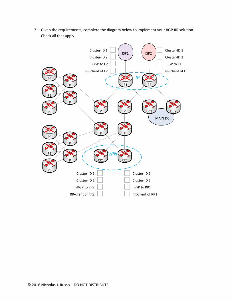
7. Given the requirements, complete the diagram below to implement your BGP RR solution.
Check all that apply.
PE
PE
PE
PE
PE
ISP1 ISP2
PE
P
P
P
P
P P
P P
RR1 RR2
IP
VPN
MAIN DC
E1 E2
DC1 DC2
Cluster-ID 1
Cluster-ID 2
RR-client of RR1
Cluster-ID 1
Cluster-ID 2
RR-client of RR2
iBGP to RR1iBGP to RR2
Cluster-ID 1
Cluster-ID 2
RR-client of E1
Cluster-ID 1
Cluster-ID 2
RR-client of E2
iBGP to E1iBGP to E2

© 2016 Nicholas J. Russo – DO NOT DISTRIBUTE
To: Designer
From: Nicky “Buffers” Johnson
Subject: Problems
Designer!
We have some pretty serious issues after implementing some of your ideas, although I’ll admit we did
deviate quite a bit. Obviously, we enabled MPLS (we used LDP everywhere) to support our VPN services,
so we didn’t feel like we needed to ask you how to do it. We just needed to allocate labels for all router
loopbacks in the network and VPN services worked great right away! We wasted some time trying to
enable LDPv6, which isn’t supported on the P routers yet, but realized it was unnecessary for VPNv6.
Whatever, I still got paid for the time at work.
We currently have IPv4 and IPv6 BGP all through the core and have serious memory and CPU over-
commitment issues due to retaining tons of routes and running bestpath non-stop (we decided to let
the full v4/v6 tables into the core for more granular traffic-engineering). Yes, I know I told you 100 times
that we used aggregation at the edge; someone did some math on the DRAM requirement and forgot a
decimal point. The CPUs of the routers were never particularly impressive, though, as this was a CAPEX
reduction technique 4 years ago when we refreshed them. We recently decided to stop running BGP
IPv6 on all routers in the core due to memory concerns since we are already carrying a good chunk of
the IPv4 table there. We haven’t implemented this yet, I just left a meeting with upper-management
where this decision was made. We think we can originate some coarse aggregates into IGP (a few
hundred) for IPv6 at the edge routers to attract egress traffic and save some memory at the cost of
optimal traffic flows; management is OK with this approach given we provide some v4/v6 path
independence, if possible. This allows us to manually balance traffic across core links so we can size
them appropriately. We still want fast convergence for both IP protocol versions in the core since our
SLA offers availability as a refundable parameter if we violate it!
Another really awkward issue is that our Netflow for IPv4 traffic in the core is not being recorded
properly. We are seeing zero customer traffic being logged yet all the IPv6 traffic is seen. We think this is
related to router performance issues but we can’t be certain since it appears consistently broken. We
use Netflow as a capacity planning tool for sizing our P-P router links, so …

© 2016 Nicholas J. Russo – DO NOT DISTRIBUTE
8. Given the performance issues, how would you minimize the effect of network failures on
business operations while satisfying as many of the requirement as possible? Choose one.
a. Use MPLS to transport all IPv4/v6 traffic + deploy FRR techniques
b. Migrate to single-protocol OSPFv3 to carry both IPv4 and IPv6 AFIs for fast convergence
c. Use single-topology ISIS with tuned down timers to affect both AFIs
d. Tune down both IPv4/v6 timers and scale up the router hardware to compensate
e. Use multi-topology ISIS, tune up IPv4 timers + deploy IP-FRR, tune down IPv6 timers

© 2016 Nicholas J. Russo – DO NOT DISTRIBUTE
9. Regarding the lack of IPv4 Netflow data being collected in the core, how can this issue be
resolved rapidly? Choose one.
a. Enable Netflow for MPLS in the core (P ingress)
b. Enable Netflow for IPv4 at the edge (PE ingress)
c. Change the loopback netmasks on the edge routers
d. Change the LDP label allocation filters for the edge router loopbacks
e. Redistribute edge router loopbacks into IGP and use route aggregation

© 2016 Nicholas J. Russo – DO NOT DISTRIBUTE
10. Regarding the lack of IPv4 Netflow data being collected in the core, how can this issue be
resolved while keeping a consistent MPLS/routing design on all LSRs? Choose one.
a. Disable and re-enable Netflow for MPLS in the core (P ingress)
b. Enable Netflow for IPv4 at the edge (PE ingress)
c. Change the loopback netmasks on the edge routers
d. Change the LDP label allocation filters for the edge router loopbacks
e. Redistribute edge router loopbacks into IGP and use route aggregation

© 2016 Nicholas J. Russo – DO NOT DISTRIBUTE
To: Designer
From: Nicky “Buffers” Johnson
Subject: Multicast deployment for IPTV services
Whew! Thanks for your help. We changed the edge router loopbacks to /31 and LDP did not allocate
labels, and thus the traffic was forwarded as native IP across the core. Definitely a good fix in the short
term, but we will go back and update our label filters later since that’s a better long-term solution. We
finally have time to fix our IPTV service issues since management believes this will be a sizable revenue
stream. As you know, we have struggled with this in the path since we’ve been using unicast for
transport, which wastes our bandwidth. Our upstream peers from ISP1 and ISP2 are going to send us
multicast flows since we don’t have any links to dedicated CDNs (and we certainly don’t have our own
multicast media being developed in house). The upstreams will be sending us traffic on groups
232.19.85.0/24, using all 256 groups in that range. This is nice from a business perspective since its
about 3 times more channels than we used to offer. They didn’t really give us more details than this, so
we quickly programmed all the customer set-tops with these groups, each of which is mapped to a TV
channel. When a customer watches a channel, the set-top signals its interest in a given group to our
Internet edge PE and we are expected to deliver the content. Problem is that our management is telling
them we have “five nines” of uptime for this entertainment service, which our competitors do not offer.
It is preferable to have a way to provide HA in a way that doesn’t waste capacity on our core links.
Admission control is nice to have, too, and we really don’t want to bloat BGP to create these delivery
trees using whatever black-magic AFIs exist there. Re-using existing infrastructure is always a plus since
it means less stuff to manage and keeps the core simple. At some point those suit-and-tie people are
going to tell us to provide IPv6 television services as well (V6-ready has become a pretty obnoxious
buzzword around here). PS: you can probably tell me enter key broke again. Someone is playing a trick
on me!

© 2016 Nicholas J. Russo – DO NOT DISTRIBUTE
11. Fill out the table regarding multicast capabilities as they relate to the core transport
requirements. Use an “X” to indicate that a technology offers the specified capability.
PIM SSM mLDP in-band RSVP P2MP TE Ingress
Replication (IR)
Admission control
BW-efficient FRR
BW-efficient general
protocol operation
Low OPEX
Doesn’t need BGP for
dynamic discovery
Doesn’t need multiple
protocols for IPv4 +
IPv6

© 2016 Nicholas J. Russo – DO NOT DISTRIBUTE
12. Given your answers from the previous question, which multicast delivery method do you
choose?
a. PIM SSM
b. mLDP in-band
c. RSVP P2MP TE
d. Ingress Replication (IR)

© 2016 Nicholas J. Russo – DO NOT DISTRIBUTE
To: Designer
From: Nicky “Buffers” Johnson
Subject: Multicast FRR
Hey,
Using mLDP in-band signaling sounds like a good solution for us. I think the #1 driver was the fact that
we didn’t need to introduce new protocols into the network and have a common way to transport IPv4
and IPv6 multicast without any flavors of PIM in the core. This is a great way for us to save OPEX and we
are looking to keep the complexity low which, in turns, drives cost savings.
We will be deploying this, but are still unsure about how to best protect the multicast flows. There are
so many options for FRR and I feel overwhelmed in choosing a suitable one to support these hop-by-hop
mLDP LSPs. I asked management about exactly what needs to be protected and in which priority order
(link, node, SRLG, etc) and they stared at me. The answer is “protect as much as you can”. Can you help?

© 2016 Nicholas J. Russo – DO NOT DISTRIBUTE
13. Given the requirements and topology, which TE-FRR strategy is best suited for this customer?
Choose one.
a. One-hop primary tunnels + automatic NHOP backups
b. One-hop primary tunnels + automatic NNHOP backups
c. Edge TE mesh between relevant LERs + NHOP backups
d. Edge TE mesh between relevant LERs + NNHOP backups
e. Core TE mesh between relevant LSRs + NHOP backups
f. Core TE mesh between relevant LSRs + NNHOP backups

© 2016 Nicholas J. Russo – DO NOT DISTRIBUTE
To: Designer
From: Nicky “Buffers” Johnson
Subject: !!!!!!!!!!!!!!!!
Wow!
This FRR design is smokin’ hot. Simple, scalable, and it just works. We haven’t missed our availability SLA
yet and the company has seen substantial growth in our IPTV service delivery division. We can protect
all the links in the core network without needing to think about it; this is pretty important to us and was
instrumental in helping us meet our SLA commitments. Management is really happy that we are able to
protect the links to the VPN RRs to ensure BGP messaging is minimally affected during failure conditions;
this has had a positive impact on our unicast VPN BGP convergence which, by transitivity, positively
affects our bottom-line. It is definitely a nice side-effect that we didn’t consider but are grateful to have.
It helps us keep OPEX down since we can still rely on basic IS-IS for routing.
Anyway, we changed the internet edge router loopbacks back to /32 because we decided to remove
Netflow from the core for capacity planning and instead configure it on the ingress PEs per customer,
which helps simplify our core network. All IPv4 internet traffic is tunneled inside MPLS again, which is
ironic since this is one of the problems we hired you to solve last month. We are debating whether to
remove IPv6 from the core … at this point, we just need to protect our customer’s IPv6 internet traffic
from any link failure. It looks like the P routers support IPv6 LFA for IS-IS.

© 2016 Nicholas J. Russo – DO NOT DISTRIBUTE
14. Given the requirements, which additional technique would you deploy to ensure IPv6 traffic
transiting the core is protected from link failures? Choose one.
a. LFA for IPv6
b. LFA + rLFA for IPv6
c. 6rd with redundant border relays
d. 6PE between LERs
e. MAP-E with second-tier MAP-T

© 2016 Nicholas J. Russo – DO NOT DISTRIBUTE
15. Arrange the 6PE migration steps in the proper sequence given the business and technical
requirements. You may assume that the IPv6 aggregates originated into IGP are the same prefix-
length as the iBGP routes advertised from E1/2 to the PEs.
a. Disable IPv6 unicast routing on P routers
b. Deactivate BGP IPv6 on P routers
c. Configure IPv6 unicast BGP+label between E1/2 and PEs
d. Configure IPv6 unicast BGP+label between E1 and E2
e. Simulate core failures to ensure FRR is functional
f. Increase IS-IS IPv6 administrative distance

© 2016 Nicholas J. Russo – DO NOT DISTRIBUTE
16. In general, how could you ensure that the VPNv4/v6 RRs are not in the forwarding path for
production traffic flows? Choose four.
a. Use IS-IS stubby area on the P routers facing the VPNv4/v6 RRs
b. Set IS-IS overload-bit on the VPNv4/v6 RRs
c. Set IS-IS attached-bit on the P routers facing the VPNv4/v6 RRs
d. Set IS-IS partition-bit on the VPNv4/v6 RRs
e. Utilize IS-IS metric adjustment; maximum-metric on RR-to-P links
f. MPLS TE explicit-paths to exclude the VPNv4/v6 RR TE-IDs
g. MPLS TE dynamic-paths + link coloring to exclude the VPNv4/v6 RR uplinks

© 2016 Nicholas J. Russo – DO NOT DISTRIBUTE
17. Given the requirements, how would you ensure that the VPNv4/v6 RRs are not in the
forwarding path for production traffic flows? Choose one.
a. Use IS-IS stubby area on the P routers facing the VPNv4/v6 RRs
b. Set IS-IS overload-bit on the VPNv4/v6 RRs
c. Set IS-IS attached-bit on the P routers facing the VPNv4/v6 RRs
d. Set IS-IS partition-bit on the VPNv4/v6 RRs
e. Utilize IS-IS metric adjustment; maximum-metric on RR-to-P links
f. MPLS TE explicit-paths to exclude the VPNv4/v6 RR TE-IDs
g. MPLS TE dynamic-paths + link coloring to exclude the VPNv4/v6 RR uplinks

© 2016 Nicholas J. Russo – DO NOT DISTRIBUTE
To: Designer
From: Nicky “Buffers” Johnson
Subject: sorry 4 bad spelling
On my smartphone trying to pick up lunch, but mgmt has been buzzing me all day. After the 6PE
migration’s success, mgmt wants to know how we can provide basic Internet browsing IPv6 service to
our DSL customers using PA addressing. Sorry I don’t have a diagram, but just look at the basic diagram
to envision our legacy DSLAMs on the PE-CE link. They support BGP-IPv4 and the DSL PE can learn
address pools from DSLAM in this way. The CPE routers are new and support stateless 6in4 tunneling &
stateless 6to4 translation techniques. Help!

© 2016 Nicholas J. Russo – DO NOT DISTRIBUTE
18. Given the requirements, what is the simplest way to provide the required IPv6 services to DSL
customers? Choose one technique and one pair of endpoints to construct your solution.
a. 6PE + CSC
b. Hub/spoke IPv6-in-IPv4
c. 6rd tunneling
d. 6to4 tunneling
e. NAT464
f. … On the CPE and DSLAM
g. … On the CPE and DSL PE
h. … On the DSL PE and DSLAM
i. … On the CPE and E1/2 routers
j. … On the DSL PE and E1/2 routers

© 2016 Nicholas J. Russo – DO NOT DISTRIBUTE
To: Designer
From: Nicky “Buffers” Johnson
Subject: Not again!
Oh boy! Another issue, this one is important. A NOC engineer thought we needed to configure customer
VRFs on the RRs so that they would retain the route-targets. Don’t worry, we already fired him, he is
cleaning out his desk now. We can’t really remove all those VRFs until the next maintenance window but
the RRs are virtual boxes and don’t have the FIB capacity for this kind of route explosion. Need
something fast! We can make configuration changes, just not VRF removal or VPN membership
modification.

© 2016 Nicholas J. Russo – DO NOT DISTRIBUTE
19. Given the needs of the business, how will you address the FIB scaling problems on the VPNv4/v6
RRs to remedy this issue? Choose one.
a. Perform aggregation on the PEs of customer routes to compensate
b. Increase administrative distance to remove routes from VRF routing table
c. Scale out RRs (quantity-wise) and deploy route-target load-splitting
d. Set the IS-IS overload bit to keep the RRs out of the MPLS transit path
e. Disable the forwarding table process entirely on the RRs
© 2016 Nicholas J. Russo – DO NOT DISTRIBUTE
To: Designer
From: Nicky “Buffers” Johnson
Subject: DCI across (13) layer-3 DCs
Hey,
As you know, our LSN logs have been piling up in our “landfill” datacenters across Europe for years. Now
that we’ve no need for LSN, we still need to retain some of the logs until their 18 month expiry date. The
problem is that we don’t know where the logs are since once the logs were written to the active DC,
they were manually copied to disk and truck-rolled to cold DCs for storage. We’ve purchased a log
consolidation application, hosted in our active DC, which is multi-tiered. The DB and application servers
exist only in the local DC, but the top tier is not a web tier, but is a discovery tier. These are sensors have
two interfaces. They discover each other using Appletalk SMRP and each DC needs to have one such
sensor (a discovery endpoint, in fact). Once the discovery endpoints find one another, they establish TCP
sessions back to the application server in client/server fashion over a second NIC. This TCP session is
used as a control channel and also for the uploading of logs for consolidation. The TCP session can be
either IPv4 or IPv6, and sometimes both, as this gives some layer-3 resilience to the application in case
one protocol stack has some internal failure. There are independent DHCPv4/v6 servers in each DC that
hand out addresses to servers, and this discovery endpoint is no exception. The application server then
compresses all the logs and writes them to disk. This application is awesome because it is smart enough
to only backhaul logs that need to be retained; logs older than 18 months are not transferred as it
wastes bandwidth.
The idea is that we will develop an architecture to support this application, then decommission all
“landfill” DCs since this is a one-time thing. Keeping these DCs isolated from our main DC is critical and
we’ve used different IGPs in each for that reason. I can’t wait to be NAT-free! I never thought we would
have so much junk to clean up after the fact.
Oh, I almost forgot to attach this diagram. All DCs are connected by dual E-LANs offered by two separate
carriers for resilience. Seems ridiculous that we paid all this money just to backhaul logs, but it’s actually
cheaper to lease these private WANs and digitally move the data than to truck roll across Europe! We
are trying to get this cleaned up fast.
We are looking for a solution that gives us policy control over which E-LAN instance to traverse to reach
a given DC while at the same time being scalable/fast to deploy. We also have a security requirement to
deploy one sensor per rack, and these sensors should not be able to communicate laterally as it could
introduce a regulatory issue. Last by not least, upper management is considering leaving the DCs in place
after the logs are removed so that we can slowly move into the cloud service provider space. Not sure if
you can help with that.
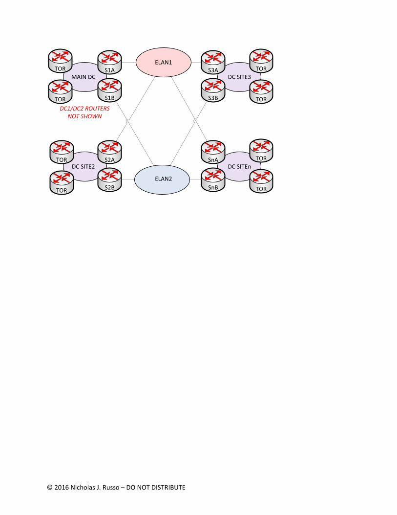
I’ve attached a diagram (on the next page) for you.
© 2016 Nicholas J. Russo – DO NOT DISTRIBUTE
MAIN DC
DC SITE2
DC SITE3
DC SITEn
ELAN1
ELAN2
S1A
S1B
S2A
S2B
S3A
S3B
SnA
SnB
TOR
TOR
TOR
TOR
TOR
TOR
TOR
TOR
DC1/DC2 ROUTERS NOT SHOWN

© 2016 Nicholas J. Russo – DO NOT DISTRIBUTE
20. Given the requirements, which high-level solution components are most appropriate for
LMNOP’s DCI solution?
a. OSPF area 0 over the E-LAN instances with separate areas in each DC
b. Migration to ISIS, with L2 over the E-LAN instances and separate L1s in each DC
c. Single area OSPF across all DCs
d. Single ISIS L2 across all DCs
e. Separate IGPs per DC with multiple BGP AS (eBGP) to exchange inter-DC routes
f. Separate IGPs per DC with single BGP AS (iBGP) to exchange inter-DC routes

© 2016 Nicholas J. Russo – DO NOT DISTRIBUTE
21. Given the requirements, how would you connect the endpoints back to the application server?
Assemble your solution by choosing 2 options.
a. Single VXLAN L2VPN to carry Appletalk and IP traffic
b. Appletalk native routing for discovery and IP native routing side by side
c. Inter-AS MPLS
d. BGP route-reflectors deployed at main DC for scale between sites
e. BGP route-servers deployed at main DC for scale between sites
f. Full-mesh BGP between all sites to support resilience + path selection

© 2016 Nicholas J. Russo – DO NOT DISTRIBUTE
To: Designer
From: Nicky “Buffers” Johnson
Subject: Next Steps
Thanks for your help so far. As I mentioned earlier, we need some kind of resilient and scalable design
here. Upper management has decided that once this application scrubs the LSN logs, we need to deliver
a flexible inter-DC network where we can provision services on the fly, ultimately enhancing our cloud
offerings. We also want to do it securely, if possible. Management thinks that we can tout our end-to-
end service offerings to attract new business. Using similar network techniques for multi-tenancy that
we use in the carrier space would help us control costs for our cloud offerings, too. Apparently we aren’t
going to scrap these other DCs, we are going to try and turn them into new profit centers.
Oh, and the cost of router memory hasn’t gotten cheaper. Any new routers you deploy need to be bare-
bones on DRAM! E-LAN2 carrier also increased their prices, so we’ve reduced the bandwidth on that
connection. Ideally the solution will allow us to do some path manipulation so that we can prefer ELAN1
over ELAN2.

© 2016 Nicholas J. Russo – DO NOT DISTRIBUTE
22. Drag and drop icons, then interconnect those items using links/sessions in order to complete the
design. The quantities of each item are shown below; if an item does not specify a quantity, it is
unlimited. The blue dotted circles represent potential device locations. Note that the two circles
in the center of the diagram are physically located in the main DC and are connected directly to
the ELAN networks as specified in the diagram.
MAIN DC
DC SITE2
DC SITE3
DC SITEn
ELAN1
ELAN2
S1A
S1B
S2A
S2B
S3A
S3B
SnA
SnB
TOR
TOR
TOR
TOR
TOR
TOR
TOR
TOR
DC1/DC2 ROUTERS NOT SHOWN
IPBGP IP Route-reflector / QTY 4
BGP IP Route-server / QTY 4
VPNBGP VPN Route-reflector / QTY 4
BGP VPN Route-server / QTY 4VPN
IP
iBGP IP session + label
iBGP VPN session
eBGP IP session + label
eBGP VPN session
THESE ARE IN THE MAIN SITE
Place the asterisk next to a router that needs to perform
mutual IGP/BGP redistribution*

© 2016 Nicholas J. Russo – DO NOT DISTRIBUTE
To: Designer
From: Nicky “Buffers” Johnson
Subject: Not so fast!
I spoke too soon in saying we were “done” with LSN technologies. We gave our customers plenty of
warning that we were going to become an IPv6-only ISP, but you know how that goes. We already
disabled LSN on our E1/E2 routers and sold the hardware cards on the gray market for some extra
money, so going back to LSN would be costly for us. I think we are just going to re-enable IPv4 transport
in our network since we can issue public IPv4 addressing to the CPEs now; let them do NAT44 one time
and we don’t have to worry about HSL and all the headaches associated with it.
As you may know, we allow our customers to multi-home to us, both for IP and VPN services. One
particularly large Internet of Things (IoT) customer, NuBrush, creates smart toothbrushes that monitor
the temperature of one’s mouth while brushing. If the temperature is outside of a normal threshold,
typically one standard deviation from the normal human mouth temperature (98.6F / 37C), it will send
an SNMP trap back to a set of centralized servers at their headquarters building. I’m not sure why
anyone would ever buy such a thing …
I wouldn’t be telling you all that unless it mattered. The customer has many sensor servers spread
throughout Western Europe and the sites that house these collection devices connect to our network.
We provide a private WAN service over MPLS for them. They use IPv6 for this since they have already
sold millions of toothbrushes at very expensive prices, so they are growing fast. The toothbrushes are
LTE-enabled and the collection sites receive updates from the toothbrushes through an LTE carrier;
those guys must be rich now.
NuBrush is connected to our network as shown below. Their primary circuit is a 40Gbps Ethernet circuit
over fiber while the backup is an STM-64 leased line from a transport provider; this is true for the HQ
only. All other sites where collection sensors exist are single-homed. We are seeing all SNMP traps being
sent to the HQ site over the STM-64 and not the 40 Gbps link. We thought BGP was smart enough to
figure this out on its own?
We need a solution that, at a minimum, sends more traffic over the primary link versus the backup link. I
would prefer that you can find a way to load-share in proportional manner but I know this will be more
complex. Keeping complexity to a minimum is very important to reduce OPEX, but also consider optimal
forwarding since that also saves OPEX. Low-impact is always better. Make some recommendations and
I’ll decide.

© 2016 Nicholas J. Russo – DO NOT DISTRIBUTE
PE
PE
PE
PE
P
P
BR1
P
PRR RR
CORE NETWORK
BR2
PE
PE
HQ
40G
STM-64

© 2016 Nicholas J. Russo – DO NOT DISTRIBUTE
23. Given the requirements, how would you design a BGP solution to resolve this issue? Assemble
your solution by choosing 2 options.
a. BGP additional-paths for VPNv6 only
b. Unique RD per NuBrush HQ VRF
c. Unique RD per NuBrush HQ and remote site VRFs
d. BGP link-bandwidth community at the NuBrush HQ VRFs
e. BGP link-bandwidth community at the NuBrush HQ and remote site VRFs
f. High BGP local-preference on primary circuit + best-external on the backup circuit at the
NuBrush HQ VRFs

© 2016 Nicholas J. Russo – DO NOT DISTRIBUTE
24. LMNOP has ruled out using BGP additional-paths and will not change RDs at the remote sites.
Continue your story from the previous question by developing a design that best meets NuBrush
and LMNOP requirements.
PE
PE
PE
P
P
BR1
P
PRR RR
CORE NETWORK
BR2
PE
PE
HQ
40G
STM-64
eBGP multipath
BGP install backup path
iBGP multipath
RD 65000:1
RD 65000:2
High local-pref in
LB extcommunity
BGP install backup path
RD 65000:1
RD 65000:2
High local-pref in
LB extcommunity
BGP install backup path
PE
Best-external
Best-external
DMZ Link-BW processing

© 2016 Nicholas J. Russo – DO NOT DISTRIBUTE
To: Designer
From: Nicky “Buffers” Johnson
Subject: Convergence issue
No time to waste on niceties here, we have a serious problem. We decided to go with the
active/standby solution using local-preference and best-external since we felt it was simpler, and not
using the STM-64 isn’t that big of a deal. Maybe a waste of money for us (and them) but now we don’t
have to mess with fancy load-sharing.
From a logical perspective, we have point-to-point circuits from our PEs to NuBrush HQ yet convergence
is very slow. During a recent construction project in Caen (NW France), the primary circuit was damaged
and several minutes’ worth of critical temperature measurement data was lost!!! Hopefully you can see
my sarcasm, but they are our customer at the end of the day. We (and the customer) expected very fast
convergence when the link was cut but it didn’t quite work out. All of the remote office PEs had their
BGP backup paths properly installed; I personally checked that myself.
Failover to the backup circuit did eventually work as expected but the customer is operating at a
degraded capacity while the link is repaired. We want to ensure this doesn’t happen again, but we aren’t
really worried about the degraded capacity on the backup link in the short term. That is what happens
when you buy a slow backup link. I have another meeting with management, likely to be lambasted for
this.
PS: We thought about enabling BFD but had some doubts, since the link appears to be point-to-point
and both the PE and CE don’t support processing BFD control packets in hardware. I don’t usually get
involved with layer-1 stuff but here is the detailed access network diagram.
PE
PE
40G
STM-64
Media Converter
Media Converter
HQCopper

© 2016 Nicholas J. Russo – DO NOT DISTRIBUTE
25. What technology would you introduce to resolve the current issue? Choose two answers to
construct your overall solution.
a. BGP keepalive tuning
b. BGP fast external fall-over
c. BFD echo mode
d. BFD asynchronous mode
e. BFD demand mode
f. … On both ends of the STM-64 link
g. … On both ends of the 40 Gbps link
h. … On the HQ router
i. … On the PE router