Embed Size (px)
Citation preview
Owner’s & Installation manualMode d’emploi et manuel d’installationManual de instrucciones y de instalación
Vehicle Rear Vision Color CameraCaméra couleur de recul pour véhiculeCámara en color de visión posterior para vehículos
CC510
2 CC510
En
glish
Owner’s M
anual
Thank you for purchasing this Clarion product.• Pleasereadthisowner’smanualinitsentiretybeforeoperatingthisequipment.• Afterreadingthismanual,besuretokeepitinahandyplace(e.g.,glovecompartment).• Checkthecontentsoftheenclosedwarrantycardandkeepitcarefullywiththismanual.
Contents1. FEATURES ...............................................................................................................22. PRECAUTIONS .........................................................................................................23. SPECIFICATIONS ....................................................................................................3 PackageContents ......................................................................................................44. TROUBLESHOOTING ..............................................................................................45. INSTALLATION ........................................................................................................5 Beforeinstallation .....................................................................................................5 Precautionswhenusingtwo-sidedtapeforinstallation .............................................5 Installingthecamera ..................................................................................................66. WIRING .....................................................................................................................6
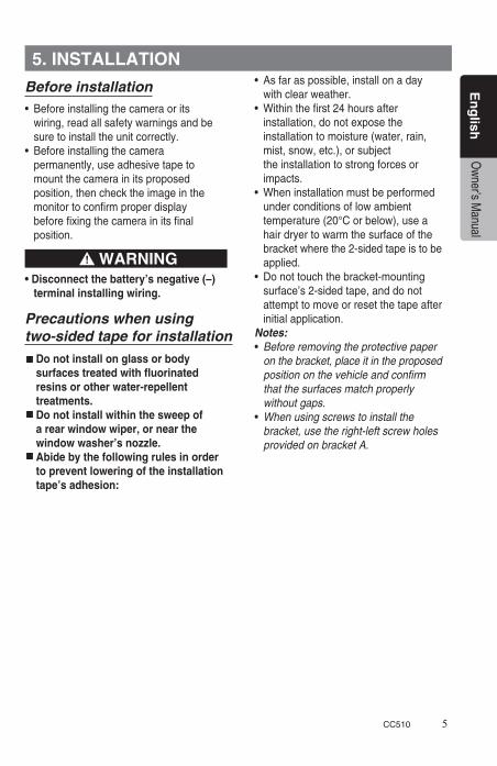
High-performance1/4”colorCMOSautoiriscameraWide-anglelensallowing150degreefieldofviewHigh-resolutionglasslensforhighimagequalityMirror-imageinversionfunctionpresentsoptimumconditionsforconfirmingrearview(sameright-leftorientationasseenthrougharearviewmirror)SmallsizeandweightforeasyinstallationDistanceguidelines(red,orange,yellow,green)
1. FEATURES
2. PRECAUTIONS
INFORMATION FOR USERS:
CHANGES OR MODIFICATIONS TO THIS PRODUCT NOT APPROVED BYTHE MANUFACTURER WILL VOID THE WARRANTY.
ThisequipmenthasbeentestedandfoundtocomplywiththelimitsforaClassBdigitaldevice,pursuanttoPart15oftheFCCRules.Theselimitsaredesignedtoprovidereasonableprotectionagainstharmfulinterferenceinaresidentialinstallation.Thisequipmentgenerates,uses,andcanradiateradiofrequencyenergyand,ifnotinstalledandusedinaccordancewiththeinstructions,maycause
harmfulinterferencetoradiocommunication.However,thereisnoguaranteethatinterferencewillnotoccurinaparticularinstallation.Ifthisequipmentdoescauseharmfulinterferencetoradioortelevisionreception,whichcanbedeterminedbyturningtheequipmentoffandon,theuserisencouragedtoconsultthedealeroranexperiencedradio/TVtechnicianforhelp.
WARNINGDistance guide lines (red, orange, yellow, green) on camera are approximate only. Distance may vary depending on vehicle and installation.

CC510 3
En
glish
Owner’s M
anual
• Thisdevicehasbeendesigned exclusively for use with a vehicular mounted rear-view system. It should notbeusedforotherpurposes.• Disconnectthevehicle’snegative(–) terminal when installing wiring.• Donotattempttodisassembleor modify this product.• Intheeventitisnecessarytodrill holes in the vehicle for mounting, confirmthatthedrillbitorcamera wiring will not strike or interfere with piping, gas tank, electrical wiring or other functional parts of the vehicle.• Donotrelysolelyonthemonitor image when reversing the vehicle. Therear-viewmonitorisanauxiliary devicemeantforconfirmingthe presenceofobstaclestotherearof thevehicle,andislimitedinitsrange. Itshouldbeusedonlyinconjunction withdirectvisualobservations.• Alwaysreverseatlowspeeds. Therear-viewmonitorproducesawide angleimage,withtheresultthat actualdistancesmaybedifferentthan theysubjectivelyappearinthemonitor.• Donotusewhentheimagingsurface or other parts are malfunctioning.• Wheninstallationandwiringare completed, confirm that the vehicle’s horn,brakeandwarninglights,and other electrical equipment function properly as designed.
• Installonlyasdirectedinthe Installation Manual.• Installaccessorypartsasdirected.• Whendrillingholesinthevehiclefor installation of wiring, always use insulated grommets in the holes to protect the wiring.• Ifholesaredrilledinthevehicleto install the camera, or when installing wiring, use silicon sealant to seal any gaps.• Donotdamageorscarthecamera wiring.• Aftercompletingthecamerawiring, usecableclampsorinsulationtape tobundlethewiringtogether.• Theimagesproducedfromtherear- view monitor are inverted right-left in the same way as images seen in the vehicle’s rearview mirrors. The image may differ depending on the vehicle type.• Donotusehigh-pressurecar washing devices around the camera. Thecameraisahigh-precision instrumentandshouldnotbesubjected tohigh-pressurewaterstreamimpacts.•Periodicallycheckthetightnessof the installation screws and retighten if necessary.
WARNING CAUTION
Powersource/voltage: DC12.0V(10.8~15.6V)Powerconsumption: Max:100mA(±20mA)Imagesensor: 1/4”ColorCMOSsensorAngleofview: 150degrees(horizontal),90degrees(vertical)Minimumsubjectillumination: 0.5lux(at50IRE)IngressProtection: IP67SNratio: 36dB(AGCON)orbetterWeight: 0.423ounces(0.0265pounds)Dimensions: 23(W)x23(H)x22(D)mm
Note:Specificationsanddesignaresubjecttochangewithoutnoticeforfurtherimprovement.
3. SPECIFICATIONS

4 CC510
En
glish
Owner’s M
anual
Package contents
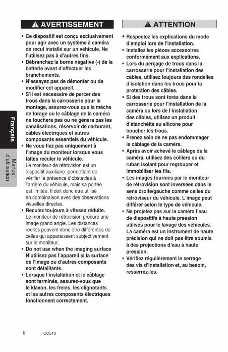
1 CamerawithattachedMountingBracket (A)(universalmounting)and7.0mcable .......... 12 Mountingbracket(B)(forusewithCAU001) ..... 13 PanheadscrewM3x4withwashers (forusewithBracketB) ...................................... 24 PanheadscrewM3x16withwashers (forusewithBracketB) ...................................... 25 Owner’smanual&Installationmanual .............. 1
Thefollowingsymptomsarenotmalfunctions.Beforehavingtheunitserviced,checkthefollowingpointsoncemore.
Symptom Reason Solution
Noimage Wiringisincompleteordisconnected.
Checkwiringonceagainandconfirmcorrectconnections.
Afuseisburnedout. Whenusinganindependentpowersupplybox,checkthefuseand,ifburnedout,replacewithanewonewiththesamecapacity(1A).Ifthefuseburnsoutrepeatedly,consultyourdealerornearestClarionServiceCenter.
Poorimageisproduce
Thelenscoverissoiled. Wipelightlywithadampsoftcloth.Donotrubharshlywithdryclothssincescratchesmaybeproduced.
Sunlightorheadlightsfromvehicleintherearareshiningdirectlyincamera.
Theimagewillreturntonormalwhenthelightstrikingthelensisremoved.
Theenvironmentistoodark. Theimagedisplaywillbepooratnightordim.Theimagewillreturntonormalinconditionsofbrightenillumination.
4. TROUBLESHOOTING
CC510 5
En
glish
Owner’s M
anual
Before installation• Beforeinstallingthecameraorits wiring,readallsafetywarningsandbe suretoinstalltheunitcorrectly.• Beforeinstallingthecamera permanently,useadhesivetapeto mountthecamerainitsproposed position,thenchecktheimageinthe monitortoconfirmproperdisplay beforefixingthecamerainitsfinal position.
•Disconnectthebattery’snegative(–) terminal installing wiring.
Precautions when usingtwo-sided tape for installation
• Asfaraspossible,installonaday withclearweather.• Withinthefirst24hoursafter installation,donotexposethe installationtomoisture(water,rain, mist,snow,etc.),orsubject theinstallationtostrongforcesor impacts.• Wheninstallationmustbeperformed underconditionsoflowambient temperature(20°Corbelow),usea hairdryertowarmthesurfaceofthe bracketwherethe2-sidedtapeistobe applied.• Donottouchthebracket-mounting surface’s2-sidedtape,anddonot attempttomoveorresetthetapeafter initial application.Notes:• Before removing the protective paper on the bracket, place it in the proposed position on the vehicle and confirm that the surfaces match properly without gaps.• When using screws to install the bracket, use the right-left screw holes provided on bracket A.
Donotinstallonglassorbodysurfaces treated with fluorinated resins or other water-repellent treatments.Do not install within the sweep of a rear window wiper, or near the window washer’s nozzle.Abidebythefollowingrulesinorderto prevent lowering of the installation tape’s adhesion:
5. INSTALLATION
WARNING
6 CC510
En
glish
Owner’s M
anual
Installing the camera
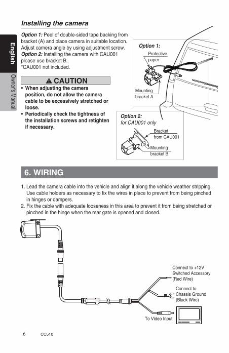
Option 1:Peelofdouble-sidedtapebackingfrombracket(A)andplacecamerainsuitablelocation.Adjustcameraanglebyusingadjustmentscrew.Option 2:InstallingthecamerawithCAU001pleaseusebracketB.*CAU001notincluded.
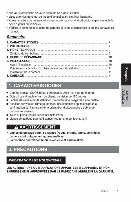
1.Leadthecameracableintothevehicleandalignitalongthevehicleweatherstripping. Usecableholdersasnecessarytofixthewiresinplacetopreventfrombeingpinched inhingesordampers.2.Fixthecablewithadequateloosenessinthisareatopreventitfrombeingstretchedor pinchedinthehingewhenthereargateisopenedandclosed.
Connectto+12VSwitchedAccessory(RedWire)
ConnecttoChassisGround(BlackWire)
ToVideoInput
Protectivepaper
MountingbracketA
BracketfromCAU001
MountingbracketB
Option 1:
Option 2:for CAU001 only
• Whenadjustingthecamera position, do not allow the camera cabletobeexcessivelystretchedor loose.• Periodicallycheckthetightnessof the installation screws and retighten if necessary.
CAUTION
6. WIRING
CC510 7
Fran
çaisM
anueld’utilisation
NousvousremercionsdevotreachatdeceproduitClarion.• Lisezattentivementtoutcemoded’emploiavantd’utiliserl’appareil.• Aprèslalecturedecemanuel,conservez-ledansunendroitpratique(parexemplela boîteàgantsduvéhicule).• Vérifiezlecontenudelacartedegarantieci-jointeetconservez-laenlieusûravecce manuel.
Sommaire1. CARACTÉRISTIQUES .........................................................................................72. PRÉCAUTIONS .....................................................................................................73. FICHE TECHNIQUE .............................................................................................9 Contenudel’emballage .........................................................................................94. GUIDE DE DÉPANNAGE ......................................................................................105. INSTALLATION ....................................................................................................10 Avantl’installation .................................................................................................10 Précautionsàl’emploidurubanbi-facepourl’installation .....................................11 Installationdelacaméra ........................................................................................116. CABLAGE ............................................................................................................11
CaméracouleurCMOShauteperformanceAutoIris¼po(6.35mm)Objectifgrandangleoffrantunchampdevisionde150degrésLentilledeverreàhautedéfinition,procurantuneimagedehautequalitéFonctiond’inversiond’image,donnantdesconditionsoptimalespourlaconfirmationsurl’arrière(mêmeorientationdroite/gauchequ’obtenuedansunrétroviseur)Tailleetpoidsréduits,facilitantl’installationLignesdeguidagepourladistance(rouge,orange,jaune,vert)
INFORMATION AUX UTILISATEURS:
LES ALTÉRATIONS OU MODIFICATIONS APPORTÉES A L’APPAREIL ET NON EXPRESSÉMENT APPROUVÉES PAR LE FABRICANT ANNULENT LA GARANTIE.
• Lignesdeguidagepourladistance(rouge,orange,jaune,vert)dela caméra sont uniquement approximatives.• Ladistancepeutvarierselonlevéhiculeetl’installation.
1. CARACTÉRISTIQUES
2. PRÉCAUTIONS
AVERTISSEMENT
8 CC510
Fran
çaisM
anueld’utilisation
• Cedispositifestconçuexclusivement pour agir avec un système à caméra de recul installé sur un véhicule. Ne l’utilisez pas à d’autres fins.• Débranchezlabornenégative(-)dela batterieavantd’effectuerles branchements.• N’essayezpasdedémonteroude modifier cet appareil.• S’ilestnécessairedepercerdes trous dans la carrosserie pour le montage, assurez-vous que la mèche deforageoulecâblagedelacaméra ne touchera pas ou ne gênera pas les canalisations,réservoirdecarburant, câblesélectriquesetautres composants essentiels du véhicule.• Nevousfiezpasuniquementà l’image du moniteur lorsque vous faites reculer le véhicule. Lemoniteurderétrovisionestun dispositifauxiliaire,permettantde vérifierlaprésenced’obstaclesà l’arrièreduvéhicule,maissaportée estlimitée.Ildoitdoncêtreutilisé encombinaisonavecdesobservations visuellesdirectes.• Reculeztoujoursàvitesseréduite. Lemoniteurderétrovisionprocureune imagegrandangle.Lesdistances réellespeuventdoncêtredifférentesde cellesquiapparaissentsubjectivement surlemoniteur.• Donotusewhentheimagingsurface N’utilisez pas l’appareil si la surface de l’image ou d’autres composants sont défaillants.• Lorsquel’installationetlecâblage sont terminés, assurez-vous que le klaxon, les freins, les clignotants et les autres composants électriques fonctionnent correctement.
• Respectez les explications du mode d’emploi lors de l’installation.• Installezlespiècesaccessoires conformément aux explications.• Lorsduperçagedetrousdansla carrosserie pour l’installation des câbles,utiliseztoujoursdesrondelles d’isolation dans les trous pour la protectiondescâbles.• Sidestroussontforésdansla carrosserie pour l’installation de la caméra ou lors de l’installation descâbles,utilisezunproduit d’étanchéité au silicone pour boucherlestrous.• Prenezsoindenepasendommager lecâblagedelacaméra.• Aprèsavoirachevélecâblagedela caméra, utilisez des colliers ou du rubanisolantpourregrouperet immobiliserlesfils.• Lesimagesfourniesparlemoniteur de rétrovision sont inversées dans le sens droite/gauche comme celles du rétroviseur du véhicule. L’image peut différer selon le type de véhicule.• Neprojetezpassurlacaméral’eau de dispositifs à haute pression utilisés pour le lavage des véhicules. La caméra est un instrument de haute précision qui ne doit pas être soumis àdesprojectionsd’eauàhaute pression.• Vérifiezrégulièrementleserrage desvisd’installationet,aubesoin, resserrez-les.
ATTENTIONAVERTISSEMENT
CC510 9
Fran
çaisM
anueld’utilisation
Sourced’alimentation/tension: CC12.0V(10.8~15.6V)Consommation: 100mA(±20mA)Capteurd’image: CapteurCMOScouleur¼po(63,5mm)Angledevue:Env: 150degrés(horizontal)90degrés(vertical)Éclairageminimumdusujet: 0,5lux(à50IRE)Indicedeprotection: IP67RapportSignal/Bruit: 36dB(AGCactivé)ouplusPoids: 0,423onces(0,0265livres/11,9grammes)Dimensions: 23(L)x23(H)x22(P)mm
Remarque:Spécificationsetdesignsousréservedemodificationssanspréavisenraisond’améliorationséventuelles.
Contenu de l’emballage
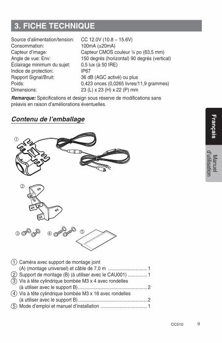
1 Caméraavecsupportdemontagejoint (A)(montageuniversel)etcâblede7,0m ..............................12 Supportdemontage(B)(àutiliseravecleCAU001) ...............13 VisàtêtecylindriquebombéeM3x4avecrondelles (àutiliseraveclesupportB) .....................................................24 VisàtêtecylindriquebombéeM3x16avecrondelles (àutiliseraveclesupportB) .....................................................25 Moded’emploietmanueld’installation ....................................1
3. FICHE TECHNIQUE
10 CC510
Fran
çaisM
anueld’utilisation
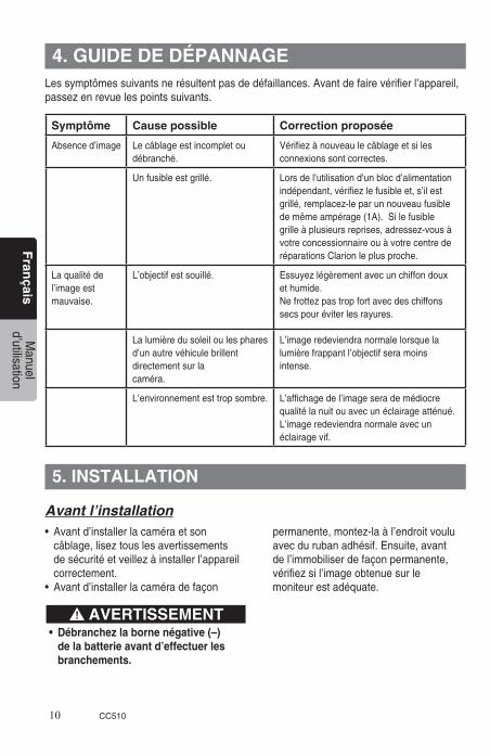
Avant l’installation• Avantd’installerlacaméraetson câblage,liseztouslesavertissements desécuritéetveillezàinstallerl’appareil correctement.• Avantd’installerlacaméradefaçon
permanente,montez-laàl’endroitvoulu avecdurubanadhésif.Ensuite,avant del’immobiliserdefaçonpermanente, vérifiezsil’imageobtenuesurle moniteurestadéquate.
• Débranchezlabornenégative(–) delabatterieavantd’effectuerles branchements.
Lessymptômessuivantsnerésultentpasdedéfaillances.Avantdefairevérifierl’appareil,passezenrevuelespointssuivants.
Symptôme Causepossible Correction proposée
Absenced’image Lecâblageestincompletoudébranché.
Vérifiezànouveaulecâblageetsilesconnexionssontcorrectes.
Unfusibleestgrillé. Lorsdel’utilisationd’unblocd’alimentationindépendant,vérifiezlefusibleet,s’ilestgrillé,remplacez-leparunnouveaufusibledemêmeampérage(1A).Silefusiblegrilleàplusieursreprises,adressez-vousàvotreconcessionnaireouàvotrecentrederéparationsClarionleplusproche.
Laqualitédel’imageestmauvaise.
L’objectifestsouillé. Essuyezlégèrementavecunchiffondouxethumide.Nefrottezpastropfortavecdeschiffonssecspouréviterlesrayures.
Lalumièredusoleiloulespharesd’unautrevéhiculebrillentdirectementsurlacaméra.
L’imageredeviendranormalelorsquelalumièrefrappantl’objectifseramoinsintense.
L’environnementesttropsombre. L’affichagedel’imageserademédiocrequalitélanuitouavecunéclairageatténué.L’imageredeviendranormaleavecunéclairagevif.
4. GUIDE DE DÉPANNAGE
5. INSTALLATION
AVERTISSEMENT
CC510 11
Fran
çaisM
anueld’utilisation
Précautions à l’emploi du ruban bi-face pour l’installation
Ne l’installez pas sur des surfaces de verre ou de la carrosserie traitées avec des résines fluorées ou d’autres produits hydrofuges.Ne l’installez pas sur la surface debalayagedel’essuie-glacearrièreouprès du gicleur du lave-glace.Respectez les règles suivantes pour éviter d’amoindrir l’adhérence du ruband’installation:• Autantquepossible,installezleruban parbeautemps.• Pendantles24premièresheuresaprès l’installation,n’exposezpaslerubanà del’humidité(eau,pluie,brouillard, neige,etc.)etnelesoumettezpasà desfortsimpacts.• Sil’installationdoitêtrefaitesousune températureambiantebasse(moinsde
20°C),servez-vousd’unsèche- cheveuxpourréchaufferlasurfacede l’appliquesurlaquellelerubanbi-face seraappliqué.• Netouchezpaslerubanbi-facepourla surfacedemontagedel’appliqueet n’essayezplusdebougeroud’ajuster lerubanaprèsqu’ilaétéappliqué.
Remarques:• Avant d’enlever le papier protecteur de l’applique, placez-la à l’endroit souhaité sur le véhicule et assurez-vous que les surfaces correspondent parfaitement sans laisser d’interstices.• Si vous utilisez des vis pour installer l’applique, servez-vous des trous de vis gauche/droit, prévus sur l’applique A.
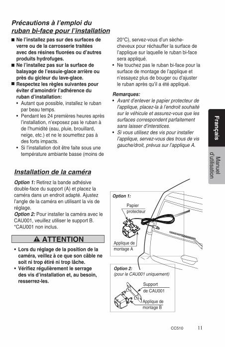
Installation de la caméra
Option 1: Retirezlabandeadhésivedouble-facedusupport(A)etplacezlacaméradansunendroitadapté.Ajustezl’angledelacaméraenutilisantlavisderéglage.Option 2: PourinstallerlacaméraavecleCAU001,veuillezutiliserlesupportB.*CAU001noninclus.
• Lorsduréglagedelapositiondela caméra,veillezàcequesoncâblene soit ni trop étiré ni trop lâche.• Vérifiezrégulièrementleserrage desvisd’installationet,aubesoin, resserrez-les.
Papierprotecteur
AppliquedemontageA
SupportdeCAU001
AppliquedemontageB
Option 1:
Option 2:(pour le CAU001 uniquement)
ATTENTION

12 CC510
Fran
çaisM
anueld’utilisation
1.Cheminezlecâbledecaméraàl’intérieurduvéhiculeetalignez-lelelongdu calfeutrageduvéhicule.Utilisezdesporte-câblessinécessairepourmaintenirlesfils enplaceafind’éviterdelespincerdanslescharnièresoulesamortisseurs.2. Laissezsuffisammentdejeuaucâbleàcetendroitpouréviterqu’ilnesoitétiréou coincédanslacharnièrelorsquelehayonestouvertetfermé.
Connecterà+12VAccessoirepermuté(Filrouge)
Connecteràlamasseduchâssis(Filnoir)
Versl’entréevidéo
6. CABLAGE
CC510 13
Esp
año
lM
anual delpropietario
MuchasgraciasporlaadquisicióndeesteproductoClarion.• Leatodoestemanualdeinstruccionesantesdeponerenfuncionamientoesteequipo.• Despuésdehaberleídoestemanual,guárdeloenunlugaraccesible(comopuedaser laguantera).• Compruebeelcontenidodelatarjetadegarantíaadjuntayguárdelaconcuidadojunto conestemanual.
Índice1. CARACTERÍSTICAS ................................................................................................132. PRECAUTIONS .........................................................................................................133. ESPECIFICACIONES ...............................................................................................15 Contenidodelpaquete ...............................................................................................154. SOLUCIÓN DE PROBLEMAS ..................................................................................165. INSTALACIÓN .........................................................................................................16 Antesdelainstalación ..............................................................................................16 Precaucionesparaelempleodecintaadhesivaporlosdoslados paralainstalación ......................................................................................................16 Instalacióndelacámara ............................................................................................176. CONEXIONES DE CABLES ....................................................................................18
CámaradeirisautomáticoconCMOSacoloresde¼pulg.dealtodesempeñoLentegranangularquepermite150gradosdecampodevisiónObjetivodevidriodealtaresoluciónparaobteneraltacalidaddeimagenLafuncióndereflejodeimagendeefectodeespejopresentalascondicionesóptimasparaconfirmarlavisiónposterior(mismaorientacióndederechaaizquierdaquelaqueseveporelespejoretrovisor)PequeñotamañoypocoperoparafacilitarsuinstalaciónIndicadordedistancia,guiademulticolor(rojo,naranja,amarilloyverde)
INFORMACIÓN PARA LOS USUARIOS:
LOS CAMBIOS O MODIFICACIONES REALIZADOS EN ESTE PRODUCTO NO APROBADOS POR EL FABRICANTE ANULARÁN LA GARANTÍA.
• Indicadordedistancia,guiademulticolor(rojo,naranja,amarilloyverde) en la cámara son únicamente aproximaciones.• Ladistanciapuedevariar,dependiendodelvehículoylainstalación.
1. CARACTERÍSTICAS
2. PRECAUCIONES
ADVERTENCIA

14 CC510
Esp
año
lM
anual delpropietario
• Esteserviciohasidoexclusivamente diseñado para ser utilizado con un sistema de visión posterior montado enunvehículo.Nodeberáutilizarse para otros propósitos.• Desconecteelterminalnegativo (-) del vehículo cuando realice las conexiones eléctricas.• Nointentedesmontarnimodificar este producto.• Enelcasoqueseanecesarioperforar orificios en el vehículo para realizar elmontaje,confirmequelabrocadel taladrooloscablesdelacámarano golpeen ni causen interferencias en lostubos,depósitodecombustible, cableadoeléctriconienotraspartes funcionales del vehículo.• Noconfíesolamenteenlaimagendel monitor cuando conduzca el vehículo en marcha atrása. Elmonitordevisióntraseraesun dispositivoauxiliarcuyopropósitoesel deconfirmarlapresenciadeobstáculos enlapartetraseradelvehículo,ysu alcanceeslimitado.Deberáutilizarse sólojuntoconlasobservaciones visualesdirectas.• Circule siempre en marcha atrás a bajasvelocidades. Elmonitordevisiónposterior produceunaimagendegranangular, porloquelasdistanciasrealespueden serdistintasalasqueaparecen subjetivamenteenelmonitor.• Noloempleecuandolasuperficiede imagen u otras partes funcionen mal.• Cuandosehayacompletadola instalación y las conexiones eléctricas,confirmequelabocina, los frenos y las luces de aviso y demás accesorios eléctricos del vehículo funcionen correctamente de la forma en que han sido diseñados.
• Instálelosólocomoseindicaenel manual de instalación.• Instaleloscomponentesaccesorios como se indica.• Cuandoperforeorificiosenel vehículo para realizar la instalación oelcableado,empleesiempreanillos protectores aislados en los orificios paraprotegerelcableado.• Siseperforarorificiosenelvehículo para instalar la cámara, o cuando se instaleelcableado,empleeagente deobturacióndesiliconapara obturartodosloshuelgos.• Nodañeniraspeelcableadodela cámara.• Despuésdehabercompletadoel cableadodelacámara,emplee abrazaderasocintaaislantepara agrupar los conductores.• Lasimágenesproducidasdesdeel monitor de visión posterior se invierten de derecha a izquierda del mismo modo que las imágenes que sevenporlosespejosretrovisores del vehículo. La imagen puede ser distinta dependiendo del tipo de vehículo.• Noempleedispositivosdelavadode automóviles a alta presión en torno a la cámara. Lacámaraesuninstrumentodealta precisiónynodebesometersealos impactosdelaguaaaltapresión.• Compruebeperiódicamenteelapriete de los tornillos de instalación y apriételos si es necesario.
ADVERTENCIA PRECAUCIÓN

CC510 15
Esp
año
lM
anual delpropietario
Contenido del paquete
1 Cámaraconsoportedemontaje (A)(montajeuniversal)ycablede7,0m ................................12 Soportedemontaje(B)(parausarseconCAU001) ...............13 TornillosdecabezatroncocónicaM3x4con arandelas(parausarseconelsoporteB) ...............................24 TornillosdecabezatroncocónicaM3x16con arandelas(parausarseconelsoporteB) ...............................25 Manualdeinstruccionesymanualdeinstalación ..................1
Alimentación/tensión: DC12.0V(10.8~15.6V)Consumodeenergía: Max:100mA(±20mA)Sensordeimagen: SensorCMOSacoloresde¼pulgÁngulodevisión: 150grados(horizontal),90grados(vertical)Iluminaciónmínimadelsujeto: 0,5lux(a50IRE)Proteccióndeingreso: IP67Relacióndeseñal/ruido: 36dB(AGCactivado)omejorPeso: 0,423onzas(0,0265libras)Dimensiones: 23(An)x23(Al)x22(Pfr)mm
Nota:Especificacionesydiseñosujetosacambiossinprevioavisoporrazonesdemejorasdelproducto.
3. ESPECIFICACIONES

16 CC510
Esp
año
lM
anual delpropietario
Lossíntomassiguientesnosondemalfuncionamiento.Antesdesolicitarelserviciotécnicodelaunidad,compruebeotravezlospuntossiguientes.
Síntoma Motivo Solución
No hay imagen El cableado está incompleto odesconectado.
Compruebe de nuevo el cableado y confirmeque las conexiones sean correctas.
Se ha quemado un fusible. Cuando utilice una fuente de alimentación eléctrica independiente, revise el fusible y, si está quemado, remplácelo con uno nuevo de la misma capacidad (1A). Si el fusible se quema repetidas veces, consulte con su distribuidor o Centro de Servicio Clarion más cercano.
Se produce unaimageninsatisfactoria
El objetivo está sucio. Limpie ligeramente con un paño suave y húmedo.No frote con fuerza con paños secos, puede producir ralladuras.
La luz del sol o la de los faros de un vehículo que circula detrás llega directamente a la cámara.
La imagen volverá a la normalidad cuando desaparezca la luz que llega al objetivo.
En entorno es demasiado oscuro. La visualización de la imagen será mala en la noche o con luz tenue.La imagen regresará a la normalidad en condiciones de iluminación brillante.
Antes de la instalación•Antesdeinstalarlacámaraosu cableado,leatodaslasadvertenciasde seguridadyasegúresedeinstalar correctamentelaunidad.• Antesdeinstalarpermanentementela cámara,empleecintaadhesiva paramontarlacámaraenlaposición propuesta,ycompruebeentoncesla imagendelmonitorparaconfirmarquela visualizaciónseaadecuadaantesdefijar lacámaraensuposicióndefinitiva.
• Desconecteelterminalnegativo(–)de labateríacuandorealicelasconexio nes eléctricas.
Precauciones para el empleode cinta adhesiva por los dos lados para la instalación
No efectúe la instalación en superficies de vidrio ni de la carrocería tratadas con resinas a basedeflúorniconotrostratamientos para repulsión del agua.No la instale dentro del espacio de barridodellimpiadordelaventanillatrasera,nicercadelaboquilladellavador de la ventanilla.Respete las reglas siguientes para evitar la reducción de la adhesión de la cinta de instalación:
4. SOLUCIÓN DE PROBLEMAS
5. INSTALACIÓN
ADVERTENCIA
CC510 17
Esp
año
lM
anual delpropietario
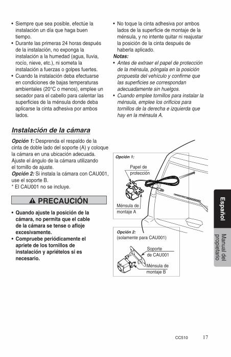
Instalación de la cámara
Opción 1: Desprendaelrespaldodelacintadedobleladodelsoporte(A)ycoloquelacámaraenunaubicaciónadecuada.Ajusteelángulodelacámarautilizandoeltornillodeajuste.Opción 2: SiinstalalacámaraconCAU001,useelsoporteB.*ElCAU001noseincluye.
• Quandoajustelaposicióndela cámara,nopermitaqueelcable delacámarasetenseoafloje excesivamente.• Compruebeperiódicamenteel apriete de los tornillos de instalación y apriételos si es necesario.
• Siemprequeseaposible,efectúela instalaciónundíaquehagabuen tiempo.• Durantelasprimeras24horasdespués delainstalación,noexpongala instalaciónalahumedad(agua,lluvia, rocío,nieve,etc.),nisometala instalaciónafuerzasogolpesfuertes.• Cuandolainstalacióndebaefectuarse encondicionesdebajastemperaturas ambientales(20°Comenos),empleeun secadorparaelcabelloparacalentarlas superficiesdelaménsuladondedeba aplicarselacintaadhesivaporambos lados.
• Notoquelacintaadhesivaporambos ladosdelasuperficiedemontajedela ménsula,ynointentequitarnireajustar laposicióndelacintadespuésde haberlaaplicado.Notas:• Antes de extraer el papel de protección de la ménsula, póngala en la posición propuesta del vehículo y confirme que las superficies se correspondan adecuadamente sin huelgos.• Cuando emplee tornillos para instalar la ménsula, emplee los orificios para tornillos de la derecha e izquierda que hay en la ménsula A.
PRECAUCIÓN
Papeldeprotección
MénsulademontajeA
SoportedeCAU001
MénsulademontajeB
Opción 1:
Opción 2:(solamenteparaCAU001)
18 CC510
Esp
año
lM
anual delpropietario
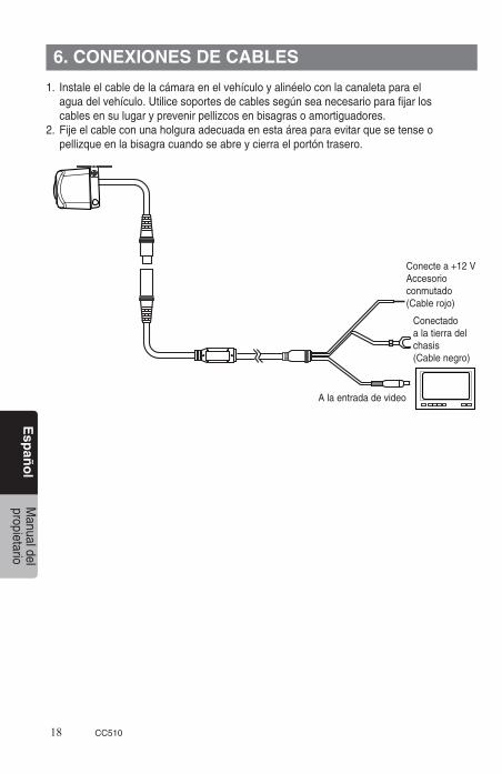
1. Instaleelcabledelacámaraenelvehículoyalinéeloconlacanaletaparael aguadelvehículo.Utilicesoportesdecablessegúnseanecesarioparafijarlos cablesensulugaryprevenirpellizcosenbisagrasoamortiguadores.2.Fijeelcableconunaholguraadecuadaenestaáreaparaevitarquesetenseo pellizqueenlabisagracuandoseabreycierraelportóntrasero.
Conectea+12VAccesorioconmutado(Cablerojo)
Conectadoalatierradelchasis(Cablenegro)
Alaentradadevideo
6. CONEXIONES DE CABLES

Conectea+12VAccesorioconmutado(Cablerojo)
Conectadoalatierradelchasis(Cablenegro)

Clarion Corporation of AmericaAllRightsReserved.Copyright©2012ClarionCorporationofAmerica
PrintedinChina/ImprimeauChiné/ImpresoenChina
03/2013 CC510