Embed Size (px)
Citation preview
Test Suite for the CAx Implementor Forum
Round 41J
September 2017 – March 2018
Release 1.1
January 30, 2018
Contacts Jochen Boy PROSTEP AG Dolivostraße 11 64293 Darmstadt / Germany [email protected]
Jean-Marc Crepel AFNeT 30, Rue de Miromesnil 75008 Paris / France [email protected]
Phil Rosché ACCR, LLC. 125 King Charles Circle Summerville, SC 29485 USA [email protected]
© CAx Implementor Forum
CAx Implementor Forum Round 41J Test Suite Version 1.1, January 30, 2018
© CAx Implementor Forum http://www.cax-if.de/ 2 http://www.cax-if.org/
Table of Contents 1 Introduction .......................................................................................................... 3
1.1 Functionality tested in this round ............................................................................... 3 1.2 General testing instructions for this round .................................................................. 4 1.3 Testing Schedule ....................................................................................................... 4 1.4 Copyrights on Test Cases ......................................................................................... 4
2 Synthetic Test Case Specifications ................................................................... 5
2.1 Test Case SP5: Semantic PMI Representation, including STEP File Library ............. 5 2.2 Test Case TGP3: 3D Tessellated Geometry & Tessellated PMI Presentation ........... 9 2.3 Test Case AS3: AP242 BO Model XML TC Migration .............................................. 12 2.4 Test Case PDM1: AP242 BO Model XML PDM Interoperability ............................... 15 2.5 Test Case SM2: Alternative Part Shapes / Sheet Metal ........................................... 17 2.6 Test Case KM1: Kinematics..................................................................................... 21 2.7 Test Case CO2: Composite Materials (Ply Contour) ................................................ 23 2.8 Test Case CO3: Composite Materials (3D Explicit Ply Representation) ................... 26
Annex A NIST Model Translation Configuration Considerations ..................... 30
Annex B NIST Model Definitions .......................................................................... 32
Annex C Composite Data model for Rosette Type 2 .......................................... 38
List of Figures Figure 1: CAx-IF Round41J Schedule .................................................................................... 4 Figure 2: Illustration of the Torque Converter model ............................................................. 13 Figure 3: Torque Converter structure and indication if included attributes............................. 14 Figure 4: Illustration of SM2, showing folded and unfolded shapes simultaneously .............. 18 Figure 5: Illustration of PMI to be added to the unfolded shape ............................................ 19 Figure 6: Illustration of the KM1 test models ......................................................................... 22 Figure 7: Illustration of the CO2 Test Case ........................................................................... 24 Figure 8: Illustration of the CO3 Test Case ........................................................................... 27 Figure 9: NX 8 vs. NX 9 Dimension Display Names ............................................................. 31 Figure 10: ASME_Y14.37_RosetteType2.CATPart .............................................................. 38 Figure 11: Old Recommendation from AP203e2 .................................................................. 38 Figure 12: New Recommendations AP242 E2 ...................................................................... 39
Document History Release Date Change
1.0 2017-12-22 Initial Release 1.1 2018-01-30 Addition of statistics for KM1

CAx Implementor Forum Round 41J Test Suite Version 1.1, January 30, 2018
© CAx Implementor Forum http://www.cax-if.de/ 3 http://www.cax-if.org/
1 Introduction This document describes the suite of test cases to be used for the forty-first round of testing of the CAx Implementor Forum (CAx-IF). The CAx-IF is a joint testing forum, organized and fa-cilitated by AFNeT, PDES, Inc., and the prostep ivip Association. The test rounds of the CAx-IF concentrate primarily on testing the interoperability and compliance of STEP processors based on AP242. The test rounds in general combine testing of synthetic and production models. Production models will in most cases be provided by the member companies of the organizations AFNeT, PDES, Inc., and prostep ivip Association. When production models are not available from the member companies, “production-like” models will be solicited from the various CAx-IF partici-pants. This test suite includes synthetic models for testing the following capabilities: Product Manu-facturing Information (PMI), both as Graphic Presentation and as Semantic Representation, 3D Tessellated Geometry, Composite Materials, Kinematics, and Assembly Structure with Ex-ternal References in AP242 BO Model XML format.
1.1 Functionality tested in this round Functionality tested in this round relates to:
• Product Manufacturing Information (PMI) describes the capability to embed infor-mation about dimensions, tolerances and other parameters which are necessary input for the manufacturing and measuring of the part from the 3D model. In Round36J, the focus will be on the two approaches for the transfer of PMI in the 3D model:
o “Tessellated Presentation” refers to breaking down each annotation into tessel-lated elements as supported by AP242, and exchanging them as geometry. This preserves the exact shape of the annotation, but is human readable only. The test will include section views as well.
o “Semantic Representation” refers to the intelligent transfer of PMI data in an associative and re-usable way. This scenario aims towards driving downstream usage and later modifications of the model. The data is machine-readable, but not necessarily visible in the 3D model. The test also includes additional presen-tation data, which can be linked to the corresponding PMI representation.
• Tessellated Geometry is a simplified representation for the part shape, where the ge-ometry is not given as an exact B-Rep model, but as a collection of simple planar faces (triangles) which can be easily and efficiently created and applied in specific use cases. The scope includes watertight tessellation and compressed STEP files.
• AP242 BO Model XML Assembly Structure is an implementation format introduced with AP242, and the designated process format for many applications in the aerospace and automotive industries. It will be used in combination with geometry formats match-ing the respective requirement. In the CAx-IF, the geometry files will be in STEP Part 21 format. The XML files contain the assembly structure and part master information.
• Composite Materials are made by layering various plies of material on top of each other. They can be defined in an implicit-precise way, by giving the laminate tables, ply boundaries, orientation, materials, and laminated cores; or in an explicit-tessellated way by calculating the resulting 3D Tessellated Solid. Both representations can be linked to each other.
• Kinematics is a capability in AP242 that allows describing the motion of parts over time and in relation to each other. This includes the definition of mechanisms with joints and constraints, defining the kinematic relationships between the parts, as well as mo-tions, which are defined by capturing the positions of the moving parts at discrete points in time.
CAx Implementor Forum Round 41J Test Suite Version 1.1, January 30, 2018
© CAx Implementor Forum http://www.cax-if.de/ 4 http://www.cax-if.org/
1.2 General testing instructions for this round The general procedures for communication of models and statistics are outlined in a separate document, named ‘General Testing Instructions’. The document can be retrieved from the CAx Implementor Forum web sites. The latest version is v1.13, dated September 29, 2017.
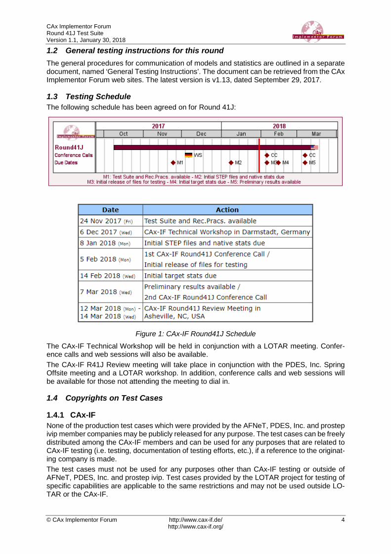
1.3 Testing Schedule The following schedule has been agreed on for Round 41J:
Figure 1: CAx-IF Round41J Schedule
The CAx-IF Technical Workshop will be held in conjunction with a LOTAR meeting. Confer-ence calls and web sessions will also be available. The CAx-IF R41J Review meeting will take place in conjunction with the PDES, Inc. Spring Offsite meeting and a LOTAR workshop. In addition, conference calls and web sessions will be available for those not attending the meeting to dial in.
1.4 Copyrights on Test Cases
1.4.1 CAx-IF None of the production test cases which were provided by the AFNeT, PDES, Inc. and prostep ivip member companies may be publicly released for any purpose. The test cases can be freely distributed among the CAx-IF members and can be used for any purposes that are related to CAx-IF testing (i.e. testing, documentation of testing efforts, etc.), if a reference to the originat-ing company is made. The test cases must not be used for any purposes other than CAx-IF testing or outside of AFNeT, PDES, Inc. and prostep ivip. Test cases provided by the LOTAR project for testing of specific capabilities are applicable to the same restrictions and may not be used outside LO-TAR or the CAx-IF.
CAx Implementor Forum Round 41J Test Suite Version 1.1, January 30, 2018
© CAx Implementor Forum http://www.cax-if.de/ 5 http://www.cax-if.org/
1.4.2 NIST The test cases developed at the National Institute of Standards and Technology (NIST) are not subject to copyright protection and are in the public domain. NIST assumes no responsi-bility for the components of the test system for use by other parties and makes no guarantees, expressed or implied, about their quality, reliability, or any other characteristic. The use of the CAD systems to create the Test Models does not imply a recommendation or endorsement by NIST. For more details, read the disclaimer at http://go.usa.gov/mGVm
2 Synthetic Test Case Specifications
2.1 Test Case SP5: Semantic PMI Representation, including STEP File Library All information about this test case can also be viewed in CAESAR on its Information page.
2.1.1 Motivation Product Manufacturing Information (PMI) is required for a number of business use cases in the context of STEP data exchange. Among others, it is a prerequisite for long-term data archiving. In addition, PMI can be used to drive downstream applications such as coordinate measuring and manufacturing. Semantic PMI Representation relates to the capability to store PMI data in the STEP file in a computer-interpretable way, so that it can be used for model redesign or downstream applica-tions. Though the definition of the data is complete, it is by itself not visible in the 3D model. Additional presentation capabilities are needed to display the data in a way that it is visible to the user in the 3D model. Addition of presentation data is optional in the SP5 test case.
2.1.2 Approach The approach to be used is described in the latest version (at least v4.0.4, dated September 1, 2016) of the “Recommended Practices for Representation and Presentation of PMI (AP242)”, which can be found in the CAx-IF member area under “Information on Round38J of Testing”. Within the PMI domain, the following functionalities are in scope of Round 41J:
• Semantic PMI Representation
• Graphic PMI Presentation (Polyline or Tessellated)
• Correct implementation and definition of the Saved Views (view layout and contents)
• Linking of PMI Representation to Presentation
• Transfer of editable PMI text as User Defined Attributes
• Semantic PMI Representation Validation Properties The AP242 schema to be used is at least the IS version (v1.36), which can be found on the public CAx-IF web sites under “Joint Testing Information”. As an alternative, the “trial” EX-PRESS Schema distributed together with the PMI Rec. Pracs. v4.0.4 can also be used for testing.
2.1.3 Testing Instructions The tests will be performed based on a verified set of test models, each with set of well-defined PMI elements. These models have been developed over the course of the “MBE PMI Valida-tion and Conformance Testing” project, which has been supported by the CAx-IF in recent test rounds.

CAx Implementor Forum Round 41J Test Suite Version 1.1, January 30, 2018
© CAx Implementor Forum http://www.cax-if.de/ 6 http://www.cax-if.org/
2.1.3.1 Test Model Overview The NIST models – in particular the original CTCs – are becoming outdated. Since their crea-tion, new releases of the respective CAD systems have become available that overcome many of the limitations noted in the original design of the models. The vendors of all involved CAD systems are encouraged to upgrade the native models to their latest release, and work on the issues listed in the validation reports which are available on the NIST homepage. The links to the test model definitions, the NIST web page for the MBE PMI Validation and Conformance Testing Project, and illustrations of the 11 test cases can be found at the end of this document in Annex B.
2.1.3.2 Test Model Access The updated native CAD files can be downloaded from the member area of the CAx-IF homep-ages under “Information on Round40J of testing”:
• CATIA V5R2016 (all CTC models; FTC models 6, 8, 9)
• NX 11 (all CTC and all FTC models)
• SolidWorks 2017 (all CTC and all FTC models)
• Inventor 2018 (all CTC and all FTC models) Even though many updates have already been made by the respective system vendors, many verification issues remain to be solved. Should new native models with further updates become available during the test round, they will be distributed and announced accordingly.
2.1.3.3 Test Model Selection In order to reduce the workload for the participating vendors, not all eleven models shall be tested in Round 41J. The following five models have chosen:
• CTC 3 & 4
• FTC 6, 8 & 9 This selection still covers a wide range of PMI elements, while reducing the number of ex-changes to be done for each interface vendor.
2.1.3.4 Test Model Configuration The following functionality shall be included in the test files provided for this round of testing, as far as it has been implemented by the CAx-IF participants and is described in the Recom-mended Practices:
• PMI Representation – the re-usable representation of PMI data should be included in all SP5 models to the extent supported by the native system.
• PMI Graphic Presentation – Many CAD systems require some minimal presentation information to be able to handle the PMI data in a model. Usually, both PMI represen-tation and presentation data are included in the same file. Thus, some form of presen-tation information shall be included in the SP5 test case as well.
• Definition of “Saved Views” – as far as supported, include the saved views defined in the models, which contain a subset of annotations in the file, and provide a pre-defined position of the model in the design space.
o Several of the models have multiple Saved Views defined: FTC-06 (3), FTC-08 (4), and FTC-09 (4). In the test case definition documents, each page of the PDF document represents one Saved View.
o For each view, a screenshot showing the model layout (displayed elements, orientation, zoom) shall be provided.

CAx Implementor Forum Round 41J Test Suite Version 1.1, January 30, 2018
© CAx Implementor Forum http://www.cax-if.de/ 7 http://www.cax-if.org/
Note that it is possible to attach several screenshots to one set of statistics in CAESAR. The name of the view shall be given as description for the screenshot.
o Both “basic” and “advanced” view implementations are allowed. o The Saved Views also shall correctly show (or hide) the part geometry, as well
as the non-solid Supplemental Geometry contained in some of the models (see section 9.4.2 / Figure 86 in the PMI Rec. Practices v4.0.4, as well as the “ele-ment visibility” chart included in the Test Case definitions (see Annex B).
• Editable PMI Text – Some information relevant for PMI is not encoded in semantic entities, but given as plain text, such as the title block information or additional text on feature control frames for instance. In the context of semantic data exchange, this con-tent needs to be editable in the target system. The approach to be used for this is based on the transfer of User Defined Attributes, and its application in the context of PMI is described in section 7.4 of the PMI Recommended Practices v4.0.4.
• Linking PMI Representation to Presentation – If a model contains PMI Representation information as well as Presentation data, the corresponding elements shall be linked together, so that a Representation element “knows” which annotation it is being pre-sented in the model. The approach to create this link is described in section 7.3 of the PMI Rec. Pracs. (v4.0.4).
• Validation Properties – All participants providing STEP files for this test case are en-couraged to include validation properties as far as supported. In particular, for vendors already working on the topic, validation properties for Semantic PMI Representation should be included in the test files, based on section 10.1 in the PMI Recommended Practices v4.0.4.
Also refer to Annex A for test model translation configuration considerations.
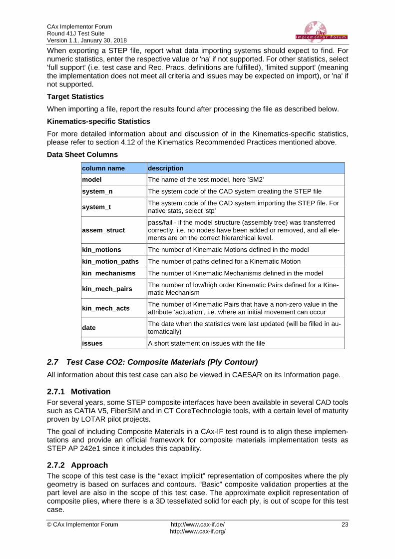
2.1.3.5 Statistics For each STEP file exported or imported for the SP5 test case, vendors must submit the cor-responding statistics. To do so, go to the [ SP5 Data Sheet ], and either fill in the web form, or upload a comma-delimited file (.csv) with the data as listed below. Native Statistics When exporting a STEP file, report what data importing systems should expect to find. For numeric statistics, enter the respective value or 'na' if not supported. For other statistics, select either 'full support' (i.e. test case and Rec. Pracs. definitions are fulfilled), 'limited support' (meaning the implementation does not meet all criteria and issues may be expected on import), or 'na' if not supported. Target Statistics When importing a STEP file, report the results after processing the file as described below. Screenshots If presentation information is contained in the test files, it shall be accompanied by correspond-ing screenshots. Note that CASEAR allows the addition of multiple screenshots per dataset. Note that in order to count the GD&T elements for the statistics, per agreement during the R22J Review Meeting, the actual STEP entity types (datum, datum_target…) shall be con-sidered. Note that based on the Round 35J results, a new count has been added for Composite Toler-ances as defined in section 6.9.9. of the PMI Rec. Pracs. (v4.0.4).
Special Round 41J Focus on these points

CAx Implementor Forum Round 41J Test Suite Version 1.1, January 30, 2018
© CAx Implementor Forum http://www.cax-if.de/ 8 http://www.cax-if.org/
Note that all statistics – native and target – shall be based on the Semantic PMI Representation data only, and not take any presentation into account. Data Sheet Columns
column name description model The name of the test model, here 'SP5'
system_n The system code of the CAD system creating the STEP file
system_t The system code of the CAD system importing the STEP file. For native stats, select 'stp'
scope A short designation for the contents of the model as defined in the Test Suite. This is for information only; there will be no results for this field.
dimensions The number of dimensions processed
datums The number of datums processed
datum_targets The number of datum targets processed
tolerances The number of tolerances (all types combined) processed, regard-less of composition.
compos_tols The number of composite tolerances processed (number of in-stances of geometric_tolerance_relationship per section 6.9.9. in the PMI Rec. Pracs. v4.0).
labels The number of labels processed
pmi_semantic_txt all/partial/none – whether 'semantic' (editable) PMI text was trans-ferred correctly (content and associativity)
pmi_semantic_val-prop
all/partial/none – whether the validation properties for Semantic PMI Representation matched for all, some or none of the semantic PMI elements.
saved_view The name of the Saved View which is the basis for the view-re-lated statistics
view_annot The number of annotations included in the specified saved view.
view_pos pass/fail, whether the model orientation and zoom factor stored for the Saved View could be restored successfully.
elem_visibility all/partial/none – whether all, some, or none of the elements to be displayed in the indicated saved view were mapped correctly into the corresponding draughting_model.
pmi_graphic_pres all/partial/none – whether the graphic PMI annotations included in the file could be processed correctly
pmi_present_val-prop
all/partial/none – whether the validation properties for Graphic PMI Presentation matched for all, some or none of the presentation el-ements.
pmi_linked_pres_rep all/partial/none – whether the Semantic PMI Representation ele-ments and (Graphic) PMI Presentation elements were linked cor-rectly together.
date The date when the statistics were last updated (will be filled in au-tomatically)
issues A short statement on issues with the file
CAx Implementor Forum Round 41J Test Suite Version 1.1, January 30, 2018
© CAx Implementor Forum http://www.cax-if.de/ 9 http://www.cax-if.org/
2.2 Test Case TGP3: 3D Tessellated Geometry & Tessellated PMI Presentation All information about this test case can also be viewed in CAESAR on its Information page.
2.2.1 Motivation In addition to use cases that require a fully defined, precise, semantic definition of the part geometry and associated PMI, as is the focus of the SP5 test case described above, there are also scenarios where the presentation of the data – geometry and annotations – for visual consumption are the primary goal. In such cases, a simplified and optimized version of the model is sufficient. For this purpose, AP242 introduced a data model for tessellated geometry, which can be used for tessellated part geometry, and also for graphic presentation of PMI in a much more efficient way than was the case with Polylines – especially in the case of filled characters. Tessellated PMI Presentation has been tested in combination with precise B-Rep geometry during the recent test rounds; in Round 41J, the focus goes back to a pure visualization scenario where the part shape as well as the graphic PMI are given as tessellated geometry.
2.2.2 Approach The approach to be used for Tessellated PMI Presentation is described in the latest version (at least v4.0.4, dated September 1, 2016) of the “Recommended Practices for Representation and Presentation of PMI (AP242)”, which can be found in the CAx-IF member area under “Information on Round38J of Testing”. The approach to be used for the definition of the part shape is defined in the “Recommended Practices for Tessellated 3D Geometry” (v1.0; 2015-12-17), available on the public CAx-IF web sites under “Joint Testing Information”. The AP242 schema to be used is the IS version (v1.36), which can be found on the public CAx-IF web sites under “Joint Testing Information”. As an alternative, the “trial” EXPRESS Schema distributed together with the PMI Rec. Pracs. v4.0.4 can also be used for testing.
2.2.3 Testing Instructions The tests will be performed based on the same set of NIST CTC and FTC models as for the SP5 test case described above.
2.2.3.1 Test Model Overview • See section 2.1.3.1 above, as well as Annex B.
2.2.3.2 Test Model Access. • See section 2.1.3.2 above.
2.2.3.3 Test Model Selection In order to reduce the workload for the participating vendors, not all eleven models shall be tested in Round 41J. The following five models have chosen:
• CTC 3 & 4
• FTC 6, 8 & 9 This selection still covers a wide range of PMI elements, while reducing the number of ex-changed to be done for each interface vendor.
2.2.3.4 Test Model Configuration The following functionality shall be included in the test file provided for this round of testing, as far as it has been implemented by the CAx-IF participants and is described in the respective Recommended Practices:
CAx Implementor Forum Round 41J Test Suite Version 1.1, January 30, 2018
© CAx Implementor Forum http://www.cax-if.de/ 10 http://www.cax-if.org/
• Tessellated 3D Geometry – include the part shape as tessellated geometry. If sup-ported, water-tight tessellation shall be used.
• Tessellated Presentation – include the PMI elements as tessellated annotations. Stroked, outline and filled fonts (and combinations) are allowed, as well as styling of the annotations (colors).
• Definition of “Saved Views” – as far as supported, include the saved views defined in the models, which contain a subset of annotations in the file, and provide a pre-defined position of the model in the design space.
o Several of the models have multiple Saved Views defined: FTC-06 (3), FTC-08 (4), and FTC-09 (4). In the test case definition documents, each page of the PDF document represents one Saved View.
o For each view, a screenshot showing the model layout (displayed elements, orientation, zoom) shall be provided. Note that it is possible to attach several screenshots to one set of statistics in CAESAR. The name of the view shall be given as description for the screenshot.
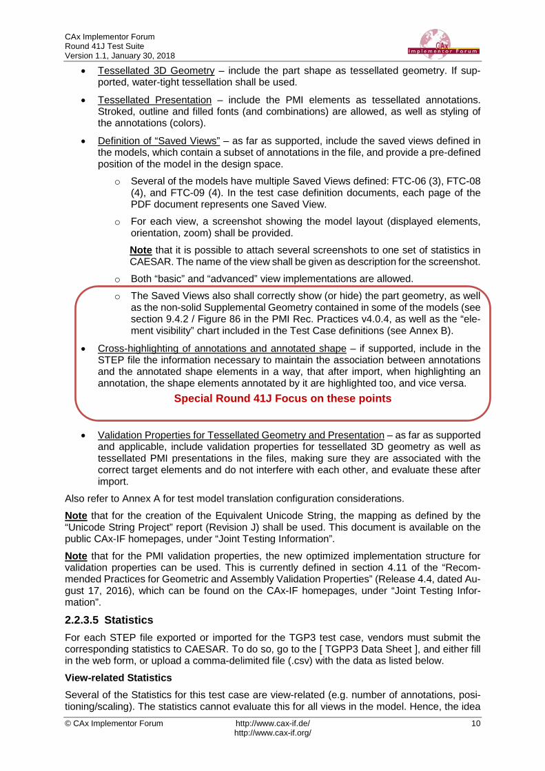
o Both “basic” and “advanced” view implementations are allowed. o The Saved Views also shall correctly show (or hide) the part geometry, as well
as the non-solid Supplemental Geometry contained in some of the models (see section 9.4.2 / Figure 86 in the PMI Rec. Practices v4.0.4, as well as the “ele-ment visibility” chart included in the Test Case definitions (see Annex B).
• Cross-highlighting of annotations and annotated shape – if supported, include in the STEP file the information necessary to maintain the association between annotations and the annotated shape elements in a way, that after import, when highlighting an annotation, the shape elements annotated by it are highlighted too, and vice versa.
• Validation Properties for Tessellated Geometry and Presentation – as far as supported and applicable, include validation properties for tessellated 3D geometry as well as tessellated PMI presentations in the files, making sure they are associated with the correct target elements and do not interfere with each other, and evaluate these after import.
Also refer to Annex A for test model translation configuration considerations. Note that for the creation of the Equivalent Unicode String, the mapping as defined by the “Unicode String Project” report (Revision J) shall be used. This document is available on the public CAx-IF homepages, under “Joint Testing Information”. Note that for the PMI validation properties, the new optimized implementation structure for validation properties can be used. This is currently defined in section 4.11 of the “Recom-mended Practices for Geometric and Assembly Validation Properties” (Release 4.4, dated Au-gust 17, 2016), which can be found on the CAx-IF homepages, under “Joint Testing Infor-mation”.
2.2.3.5 Statistics For each STEP file exported or imported for the TGP3 test case, vendors must submit the corresponding statistics to CAESAR. To do so, go to the [ TGPP3 Data Sheet ], and either fill in the web form, or upload a comma-delimited file (.csv) with the data as listed below. View-related Statistics Several of the Statistics for this test case are view-related (e.g. number of annotations, posi-tioning/scaling). The statistics cannot evaluate this for all views in the model. Hence, the idea
Special Round 41J Focus on these points
CAx Implementor Forum Round 41J Test Suite Version 1.1, January 30, 2018
© CAx Implementor Forum http://www.cax-if.de/ 11 http://www.cax-if.org/
is to select one specific (interesting) view on export and publish its name in the “Saved View” field of the statistics. It is recommended to use the first view (by name, alphabetized) in the model. Then, fill in the other view-related statistics with the values as valid for this particular view. After import, select the view with the name given in the native statistics and again provide the values valid for this view. Native Statistics When exporting a STEP file, report what data importing systems should expect to find. For numeric statistics, enter the respective value or 'na' if not supported. For other statistics, select either 'full support' (i.e. test case and Rec. Pracs. definitions are fulfilled), 'limited support' (meaning the implementation does not meet all criteria and issues may be expected on import), or 'na' if not supported. Target Statistics When importing a STEP file, report the results found after processing the file as described in the table below. Screenshots For each Saved View in the model, provide one screenshot, which illustrates the layout (dis-played geometry and annotation, model orientation, and zoom factor). Give the name of the view as the description of the screenshot. Note that in order to count the PMI elements for the statistics, per agreement during the Round 22J Review Meeting, the names of the tessellated_geometric_set shall be considered.
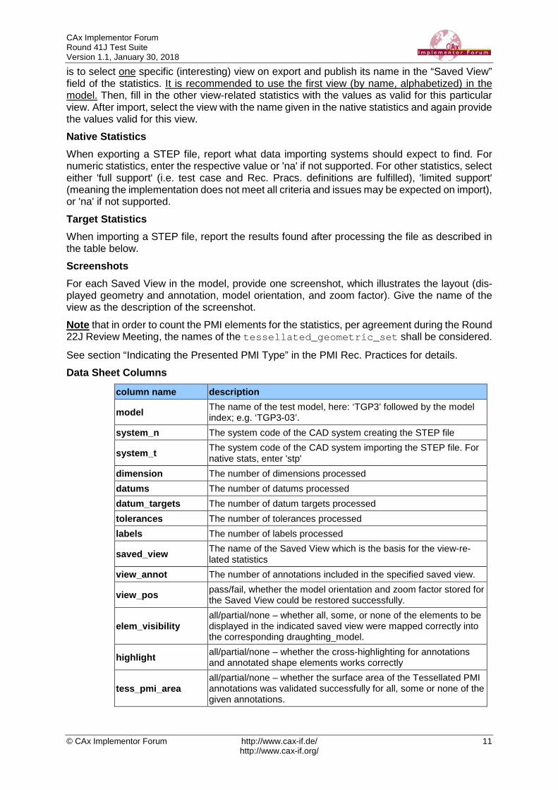
See section “Indicating the Presented PMI Type” in the PMI Rec. Practices for details. Data Sheet Columns
column name description
model The name of the test model, here: ‘TGP3’ followed by the model index; e.g. ‘TGP3-03’.
system_n The system code of the CAD system creating the STEP file
system_t The system code of the CAD system importing the STEP file. For native stats, enter 'stp'
dimension The number of dimensions processed datums The number of datums processed datum_targets The number of datum targets processed tolerances The number of tolerances processed labels The number of labels processed
saved_view The name of the Saved View which is the basis for the view-re-lated statistics
view_annot The number of annotations included in the specified saved view.
view_pos pass/fail, whether the model orientation and zoom factor stored for the Saved View could be restored successfully.
elem_visibility all/partial/none – whether all, some, or none of the elements to be displayed in the indicated saved view were mapped correctly into the corresponding draughting_model.
highlight all/partial/none – whether the cross-highlighting for annotations and annotated shape elements works correctly
tess_pmi_area all/partial/none – whether the surface area of the Tessellated PMI annotations was validated successfully for all, some or none of the given annotations.
CAx Implementor Forum Round 41J Test Suite Version 1.1, January 30, 2018
© CAx Implementor Forum http://www.cax-if.de/ 12 http://www.cax-if.org/
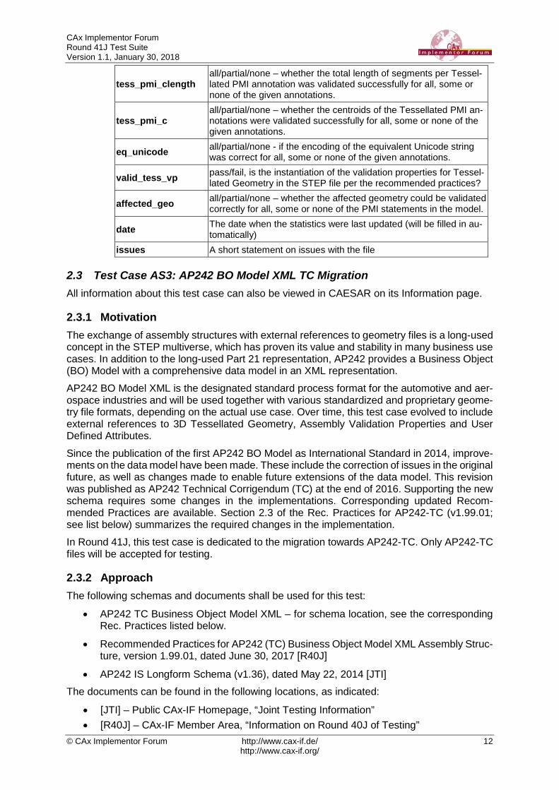
tess_pmi_clength all/partial/none – whether the total length of segments per Tessel-lated PMI annotation was validated successfully for all, some or none of the given annotations.
tess_pmi_c all/partial/none – whether the centroids of the Tessellated PMI an-notations were validated successfully for all, some or none of the given annotations.
eq_unicode all/partial/none - if the encoding of the equivalent Unicode string was correct for all, some or none of the given annotations.
valid_tess_vp pass/fail, is the instantiation of the validation properties for Tessel-lated Geometry in the STEP file per the recommended practices?
affected_geo all/partial/none – whether the affected geometry could be validated correctly for all, some or none of the PMI statements in the model.
date The date when the statistics were last updated (will be filled in au-tomatically)
issues A short statement on issues with the file
2.3 Test Case AS3: AP242 BO Model XML TC Migration All information about this test case can also be viewed in CAESAR on its Information page.
2.3.1 Motivation The exchange of assembly structures with external references to geometry files is a long-used concept in the STEP multiverse, which has proven its value and stability in many business use cases. In addition to the long-used Part 21 representation, AP242 provides a Business Object (BO) Model with a comprehensive data model in an XML representation. AP242 BO Model XML is the designated standard process format for the automotive and aer-ospace industries and will be used together with various standardized and proprietary geome-try file formats, depending on the actual use case. Over time, this test case evolved to include external references to 3D Tessellated Geometry, Assembly Validation Properties and User Defined Attributes. Since the publication of the first AP242 BO Model as International Standard in 2014, improve-ments on the data model have been made. These include the correction of issues in the original future, as well as changes made to enable future extensions of the data model. This revision was published as AP242 Technical Corrigendum (TC) at the end of 2016. Supporting the new schema requires some changes in the implementations. Corresponding updated Recom-mended Practices are available. Section 2.3 of the Rec. Practices for AP242-TC (v1.99.01; see list below) summarizes the required changes in the implementation. In Round 41J, this test case is dedicated to the migration towards AP242-TC. Only AP242-TC files will be accepted for testing.
2.3.2 Approach The following schemas and documents shall be used for this test:
• AP242 TC Business Object Model XML – for schema location, see the corresponding Rec. Practices listed below.
• Recommended Practices for AP242 (TC) Business Object Model XML Assembly Struc-ture, version 1.99.01, dated June 30, 2017 [R40J]
• AP242 IS Longform Schema (v1.36), dated May 22, 2014 [JTI] The documents can be found in the following locations, as indicated:
• [JTI] – Public CAx-IF Homepage, “Joint Testing Information” • [R40J] – CAx-IF Member Area, “Information on Round 40J of Testing”
CAx Implementor Forum Round 41J Test Suite Version 1.1, January 30, 2018
© CAx Implementor Forum http://www.cax-if.de/ 13 http://www.cax-if.org/
The focus of this test is the assembly structure exchanged in AP242 XML format. The test has the following degrees of freedom:
• File structure: o "all in one" - one XML file for the entire assembly structure, plus one STEP file
per component part o "nested" - one XML file for each node in the assembly tree, plus one STEP file
per component part. Note that in this case, component parts with part-level User Defined Attributes require an additional BO Model XML sidecar file containing these properties; see Recommended Practices section 9.3.
• Geometry format: o Precise B-Rep (STEP AP242) o Tessellated Geometry (STEP AP242)
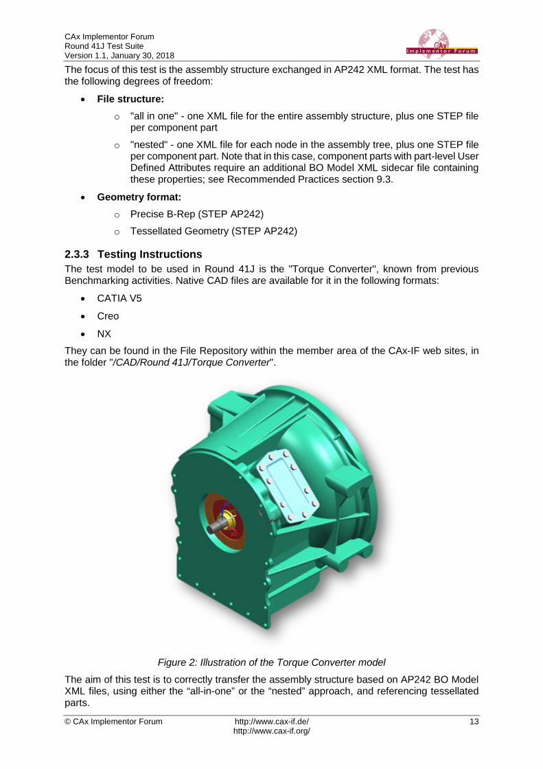
2.3.3 Testing Instructions The test model to be used in Round 41J is the "Torque Converter", known from previous Benchmarking activities. Native CAD files are available for it in the following formats:
• CATIA V5
• Creo
• NX They can be found in the File Repository within the member area of the CAx-IF web sites, in the folder "/CAD/Round 41J/Torque Converter".
Figure 2: Illustration of the Torque Converter model
The aim of this test is to correctly transfer the assembly structure based on AP242 BO Model XML files, using either the “all-in-one” or the “nested” approach, and referencing tessellated parts.
CAx Implementor Forum Round 41J Test Suite Version 1.1, January 30, 2018
© CAx Implementor Forum http://www.cax-if.de/ 14 http://www.cax-if.org/
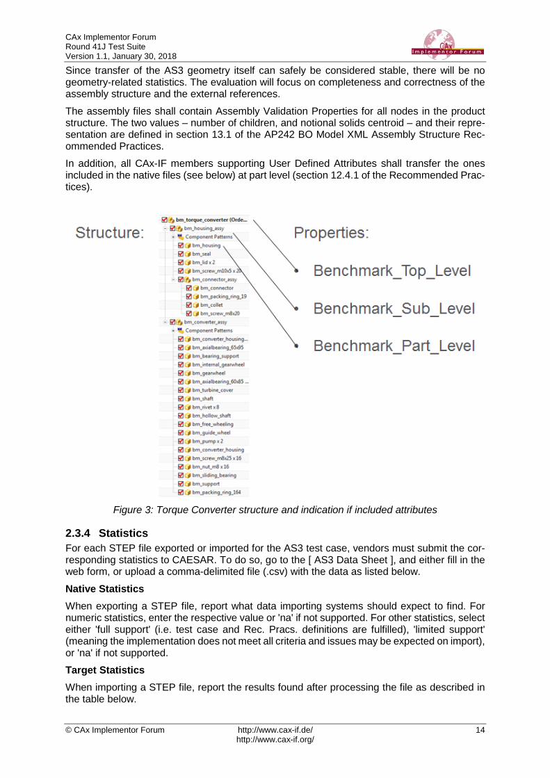
Since transfer of the AS3 geometry itself can safely be considered stable, there will be no geometry-related statistics. The evaluation will focus on completeness and correctness of the assembly structure and the external references. The assembly files shall contain Assembly Validation Properties for all nodes in the product structure. The two values – number of children, and notional solids centroid – and their repre-sentation are defined in section 13.1 of the AP242 BO Model XML Assembly Structure Rec-ommended Practices. In addition, all CAx-IF members supporting User Defined Attributes shall transfer the ones included in the native files (see below) at part level (section 12.4.1 of the Recommended Prac-tices).
Figure 3: Torque Converter structure and indication if included attributes
2.3.4 Statistics For each STEP file exported or imported for the AS3 test case, vendors must submit the cor-responding statistics to CAESAR. To do so, go to the [ AS3 Data Sheet ], and either fill in the web form, or upload a comma-delimited file (.csv) with the data as listed below. Native Statistics When exporting a STEP file, report what data importing systems should expect to find. For numeric statistics, enter the respective value or 'na' if not supported. For other statistics, select either 'full support' (i.e. test case and Rec. Pracs. definitions are fulfilled), 'limited support' (meaning the implementation does not meet all criteria and issues may be expected on import), or 'na' if not supported. Target Statistics When importing a STEP file, report the results found after processing the file as described in the table below.

CAx Implementor Forum Round 41J Test Suite Version 1.1, January 30, 2018
© CAx Implementor Forum http://www.cax-if.de/ 15 http://www.cax-if.org/
Data Sheet Columns
column name description model The name of the test model, here: ‘AS3’ system_n The system code of the CAD system creating the STEP file
system_t The system code of the CAD system importing the STEP file. For native stats, enter 'stp'
fref_found all/partial/none - indicates if all, some or none of the references to the external files can be found in the assembly structure file(s), and if they are correctly associated with the respective nodes in the assembly structure.
fref_processed all/partial/none - indicates if all, some or none of the referenced files were processed correctly to successfully construct the overall model.
assem_struct pass/fail - if the model structure (assembly tree) was transferred correctly, i.e. no nodes have been added or removed, and all ele-ments are on the correct hierarchical level.
assem_place all/partial/none - whether the placement of assembly components is correct
children pass/fail, indicates whether the number of children for each node in the assembly tree matches the AVP value given in the STEP file
valid_child pass/fail, is the instantiation of the validation property 'number of children' in the STEP file as per the recommended practices for validation properties?
notional_solids all/partial/none, whether the position of all, some or none of the assembly components in the model could be validated throug the 'notional solids' AVP.
valid_notion pass/fail, is the instantiation of the validation property 'notional sol-ids' in the STEP file as per the recommended practices for valida-tion properties?
part_attr pass/fail, have the User Defined Attributes at the part/product level been processed correctly?
date The date when the statistics were last updated (will be filled in au-tomatically)
issues A short statement on issues with the file
2.4 Test Case PDM1: AP242 BO Model XML PDM Interoperability All information about this test case can also be viewed in CAESAR on its Information page.
2.4.1 Motivation The AP242 BO Model XML is the designated standard process format for the automotive and aerospace industries. As such, it is being used in a variety of use cases. One of its main ap-plication scenarios is the exchange of Product Data Management (PDM) information. To de-velop the specific capabilities needed for this, the PDM-IF has been launched, and has just concluded its fifth round of testing. The Recommended Practices for AP242 BO Model XML Product & Assembly Structure are a joint publication of the PDM-IF with the CAx-IF and the JT-IF. One of the scenarios to be supported in this context is CAD-PDM interoperability. The PDM-IF has already imported test files from the CAx-IF, to ensure that PDM systems can manage data coming from a CAD system, which is consequently missing the document management and versioning information.
CAx Implementor Forum Round 41J Test Suite Version 1.1, January 30, 2018
© CAx Implementor Forum http://www.cax-if.de/ 16 http://www.cax-if.org/
The goal of the PDM1 test case in Round 41J is to do the opposite: import data sets coming from a PDM system into CAD systems. The CAD systems shall be able to extract the infor-mation they need (assembly structure, placement, references to component geometry files), while ignoring the additional PDM information (configuration management, document manage-ment, non-CAD documents).
2.4.2 Approach The following schemas and documents shall be used for this test:
• AP242 Business Object Model XML – for schema location, see the corresponding Rec. Practices listed below.
• Recommended Practices for AP242 (IS) Business Object Model XML Assembly Struc-ture, version 1.2.0, dated June 30, 2017 [JTI]
• Recommended Practices for AP242 (TC) Business Object Model XML Assembly Struc-ture, version 1.99.01, dated June 30, 2017 [R40J]
• AP242 IS Longform Schema (v1.36), dated May 22, 2014 [JTI] The documents can be found in the following locations, as indicated:
• [JTI] – Public CAx-IF Homepage, “Joint Testing Information”
• [R40J] – CAx-IF Member Area, “Information on Round 40J of Testing”
2.4.3 Testing Instructions PDM1 is an import-only test case. Four sets of files are provided by the PDM-IF, with the characteristics shown in the table below:
Package AP242 Version
Base Model
File Structure
Source System
pdm_conf-ps-242is IS AS1
All in one PROSTEP OpenPDM for Teamcenter
pdm_conf-tsi-242tc TC AS1 All in one T-Systems COM/PDM for Aras
pdm_nest_c3e_242tc TC AS1 Nested Dassault Systèmes 3DExperience
pdm_nest_ptc_242is IS S1 Nested PTC Windchill These files are available in a single ZIP package, located in the member areas of the CAx-IF homepage under “Information Round 41J of Testing”. Corresponding native statistics have already been entered into the PDM1 data sheet. Since everyone in the CAx-IF is familiar with the AS1 and S1 assemblies, their shapes and structures are not shown here.
2.4.4 Statistics For each STEP file imported for the PDM1 test case, vendors must submit the corresponding statistics to CAESAR. To do so, go to the [ PDM1 Data Sheet ], and either fill in the web form, or upload a comma-delimited file (.csv) with the data as listed below. Target Statistics When importing a STEP file, report the results found after processing the file as described in the table below.
CAx Implementor Forum Round 41J Test Suite Version 1.1, January 30, 2018
© CAx Implementor Forum http://www.cax-if.de/ 17 http://www.cax-if.org/
Data Sheet Columns
column name description model The name of the test model, here: ‘S2’ system_n The system code of the CAD system creating the STEP file
system_t The system code of the CAD system importing the STEP file. For native stats, enter 'stp'
fref_found all/partial/none - indicates if all, some or none of the references to the external files can be found in the assembly structure file(s), and if they are correctly associated with the respective nodes in the assembly structure.
fref_processed all/partial/none - indicates if all, some or none of the referenced files were processed correctly to successfully construct the overall model.
assem_struct pass/fail - if the model structure (assembly tree) was transferred correctly, i.e. no nodes have been added or removed, and all ele-ments are on the correct hierarchical level.
assem_place all/partial/none - whether the placement of assembly components is correct
children pass/fail, indicates whether the number of children for each node in the assembly tree matches the AVP value given in the STEP file
valid_child pass/fail, is the instantiation of the validation property 'number of children' in the STEP file as per the recommended practices for validation properties?
notional_solids all/partial/none, whether the position of all, some or none of the assembly components in the model could be validated throug the 'notional solids' AVP.
valid_notion pass/fail, is the instantiation of the validation property 'notional sol-ids' in the STEP file as per the recommended practices for valida-tion properties?
date The date when the statistics were last updated (will be filled in au-tomatically)
issues A short statement on issues with the file
2.5 Test Case SM2: Alternative Part Shapes / Sheet Metal All information about this test case can also be viewed in CAESAR on its Information page.
2.5.1 Motivation A number of scenarios have recently come up that require storing more than one shape for a particular part. Following up on tests from the previous rounds, the focus in Round 41J is to ensure association of the included PMI data with the correct shape, as well as correct definition of the geometric validation properties for both shapes.
2.5.2 Approach The approach to be used is described in the draft Recommended Practices for Alternative Shapes, version 0.1, dated May 31, 2016. It can be found in the member area of the CAx-IF homepages under “Information on Round 38J of Testing”. In particular, this test case relates to section 6 of the document “Alternative Part Shapes”. The PMI data included in this test shall comply with the PMI Recommended Practices v4.0.4, which can be found in the CAx-IF member area under “Information on Round 38J of Testing”.
CAx Implementor Forum Round 41J Test Suite Version 1.1, January 30, 2018
© CAx Implementor Forum http://www.cax-if.de/ 18 http://www.cax-if.org/
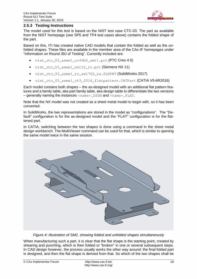
2.5.3 Testing Instructions The model used for this test is based on the NIST test case CTC-03. The part as available from the NIST homepage (see SP5 and TP4 test cases above) contains the folded shape of the part. Based on this, ITI has created native CAD models that contain the folded as well as the un-folded shapes. These files are available in the member area of the CAx-IF homepages under “Information on Round 39J of Testing”. Currently included are:
• nist_ctc_03_asme1_cr40b0_smtl.prt (PTC Creo 4.0)
• nist_ctc_03_asme1_nx110_rc.prt (Siemens NX 11)
• nist_ctc_03_asme1_rc_sw1702_ra.SLDPRT (SolidWorks 2017)
• nist_ctc_03_asme1_ct5_2016_flatpattern.CATPart (CATIA V5-6R2016)
Each model contains both shapes – the as-designed model with an additional flat pattern fea-tures and a family table, aka part family table, aka design table to differentiate the two versions – generally naming the instances <name>_DSGN and <name>_FLAT.
Note that the NX model was not created as a sheet metal model to begin with, so it has been converted. In SolidWorks, the two representations are stored in the model as “configurations”. The “De-fault” configuration is for the as-designed model and the “FLAT” configuration is for the flat-tened part. In CATIA, switching between the two shapes is done using a command in the sheet metal design workbench. The MultiViewer command can be used for that, which is similar to opening the same model twice in the same session.
Figure 4: Illustration of SM2, showing folded and unfolded shapes simultaneously
When manufacturing such a part, it is clear that the flat shape is the starting point, created by shearing and punching, which is then folded or “broken” in one or several subsequent steps. In CAD design however, the process usually works the other way around: the final folded part is designed, and then the flat shape is derived from that. So which of the two shapes shall be
CAx Implementor Forum Round 41J Test Suite Version 1.1, January 30, 2018
© CAx Implementor Forum http://www.cax-if.de/ 19 http://www.cax-if.org/
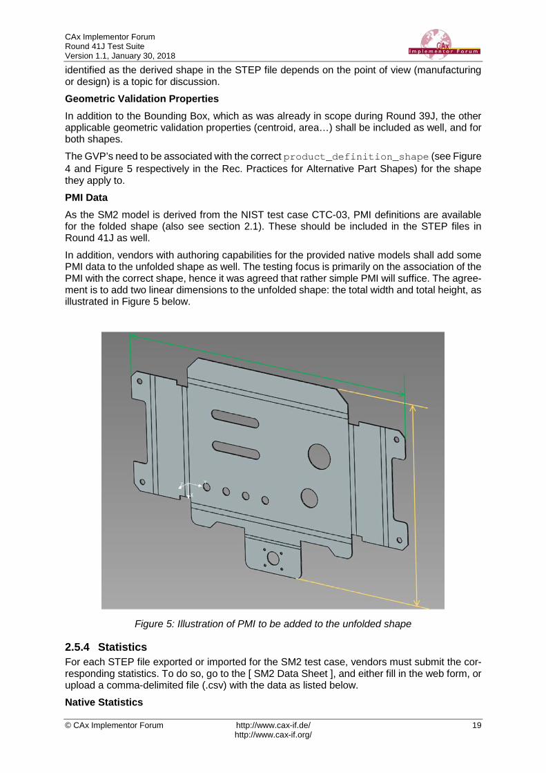
identified as the derived shape in the STEP file depends on the point of view (manufacturing or design) is a topic for discussion. Geometric Validation Properties In addition to the Bounding Box, which as was already in scope during Round 39J, the other applicable geometric validation properties (centroid, area…) shall be included as well, and for both shapes. The GVP’s need to be associated with the correct product_definition_shape (see Figure 4 and Figure 5 respectively in the Rec. Practices for Alternative Part Shapes) for the shape they apply to. PMI Data As the SM2 model is derived from the NIST test case CTC-03, PMI definitions are available for the folded shape (also see section 2.1). These should be included in the STEP files in Round 41J as well. In addition, vendors with authoring capabilities for the provided native models shall add some PMI data to the unfolded shape as well. The testing focus is primarily on the association of the PMI with the correct shape, hence it was agreed that rather simple PMI will suffice. The agree-ment is to add two linear dimensions to the unfolded shape: the total width and total height, as illustrated in Figure 5 below.
Figure 5: Illustration of PMI to be added to the unfolded shape
2.5.4 Statistics For each STEP file exported or imported for the SM2 test case, vendors must submit the cor-responding statistics. To do so, go to the [ SM2 Data Sheet ], and either fill in the web form, or upload a comma-delimited file (.csv) with the data as listed below. Native Statistics

CAx Implementor Forum Round 41J Test Suite Version 1.1, January 30, 2018
© CAx Implementor Forum http://www.cax-if.de/ 20 http://www.cax-if.org/
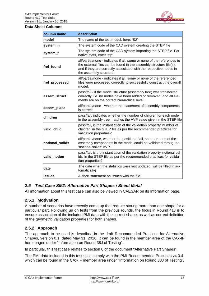
When exporting a STEP file, report what data importing systems should expect to find. For numeric statistics, enter the respective value or 'na' if not supported. For other statistics, select 'full support' (i.e. test case and Rec. Pracs. definitions are fulfilled), 'limited support' (meaning the implementation does not meet all criteria and issues may be expected on import), or 'na' if not supported. Target Statistics When importing a file, report the results found after processing the file as described below. Shape-related statistics While the information (Geometric Validation Properties and PMI) shall be given for both shapes in the model with the respective values, the statistics for GVP and PMI shall be calculated based on the folded shape only. The only exception is the Bounding Box, which is covered twice, once for each shape. Data Sheet Columns
column name description model The name of the test model, here 'SM2'
system_n The system code of the CAD system creating the STEP file
system_t The system code of the CAD system importing the STEP file. For native stats, select 'stp'
unit The unit the model is designed in
alt_shapes all/partial/none - whether the alternative part shapes in the model were processed correctly
volume Total volume of all solids
validation_volume Total volume of all solids as received via the validation property capability
valid_vol pass/fail, is the instantiation of the validation property 'volume' in the STEP file as per the recommended practices for validation properties?
area Total surface area of all solids
validation_area Total surface area of all solids in the model, as received via the validation property capability
valid_area pass/fail, is the instantiation of the validation property 'area' in the STEP file as per the recommended practices for validation proper-ties?
cx Centroid of the model cy
cz validation_cx
Centroid of the model (entire assembly) as received via the valida-tion property capability validation_cy
validation_cz
valid_cent pass/fail, is the instantiation of the validation property 'centroid' in the STEP file as per the recommended practices for validation properties?
bbox_minx The (min X, min Y, min Z) corner point of the Bounding Box (per GVP RP v3.3 or later) bbox_miny
bbox_minz
CAx Implementor Forum Round 41J Test Suite Version 1.1, January 30, 2018
© CAx Implementor Forum http://www.cax-if.de/ 21 http://www.cax-if.org/
column name description bbox_maxx
The (max X, max Y, max Z) corner point of the Bounding Box (per GVP RP v3.3 or later) bbox_maxy
bbox_maxz bbox_min_unfoldx The (min X, min Y, min Z) corner point of the Bounding Box of the
Unfolded (Flat) Shape of a Sheet Metal Part (per GVP RP v3.3 or later)
bbox_min_unfoldy bbox_min_unfoldz bbox_max_unfoldx The (max X, max Y, max Z) corner point of the Bounding Box of
the Unfolded (Flat) Shape of a Sheet Metal Part (per GVP RP v3.3 or later)
bbox_max_unfoldy bbox_max_unfoldz
valid_bbox pass/fail, is the instantiation of the validation property 'centroid' in the STEP file as per the recommended practices for validation properties?
dimensions The number of dimensions processed
datums The number of datums processed
datum_targets The number of datum targets processed
tolerances The number of tolerances (all types combined) processed, regard-less of composition.
labels The number of labels processed
date The date when the statistics were last updated (will be filled in au-tomatically)
issues A short statement on issues with the file
2.6 Test Case KM1: Kinematics All information about this test case can also be viewed in CAESAR on its Information page.
2.6.1 Motivation CAD methods have been used for many years now to design individual parts and assemblies of all sizes across all industries, from a single rivet to an entire airplane. Classically, the main focus is to ensure that the part can be manufactured correctly. Products such as cars or planes are not static, however, contain also many moving compo-nents: engine, power windows, foldable roof, windshield wipers, cargo doors, etc. Thus, Kine-matics are used to ensure they move correctly, and also to illustrate the behavior of the finished product. The use cases range from the definition of the Kinematic Mechanism, providing all relationships and constraints between the elements so that their definition can be changed in the receiving application, to Kinematic Motion, which works like a movie by providing discrete positions of the components over time. The goal is to use a neutral standard format – AP242 BO Model XML – for the definition of the Kinematic mechanisms and motion, with external references to the applicable geometry format for the respective use case.
2.6.2 Approach The approaches for “Kinematic Mechanism” as well as for “Kinematic Motion” are described in the “Recommended Practices for STEP AP242 TC Business Object Model XML Kinematics”, Version 0.7 (dated January 30, 2018), which can be found in the CAD member area of the CAx-IF web sites under “Information on Round 41J of Testing”.
CAx Implementor Forum Round 41J Test Suite Version 1.1, January 30, 2018
© CAx Implementor Forum http://www.cax-if.de/ 22 http://www.cax-if.org/
During the development of these capabilities, several new entity types have been defined to improve the implementation structure. This will be included in AP242 with the DIS release of Edition 2. To enable immediate testing, a trial XSD schema is available, which is built by ex-tending the AP242 TC schema with these new entities. It is available at the following URL: https://www.cax-if.de/xml-schema/3001/20170810/bom_20170810.xsd The corresponding name space definition is given in the aforementioned Recommended Prac-tices, Section 1.1.2.
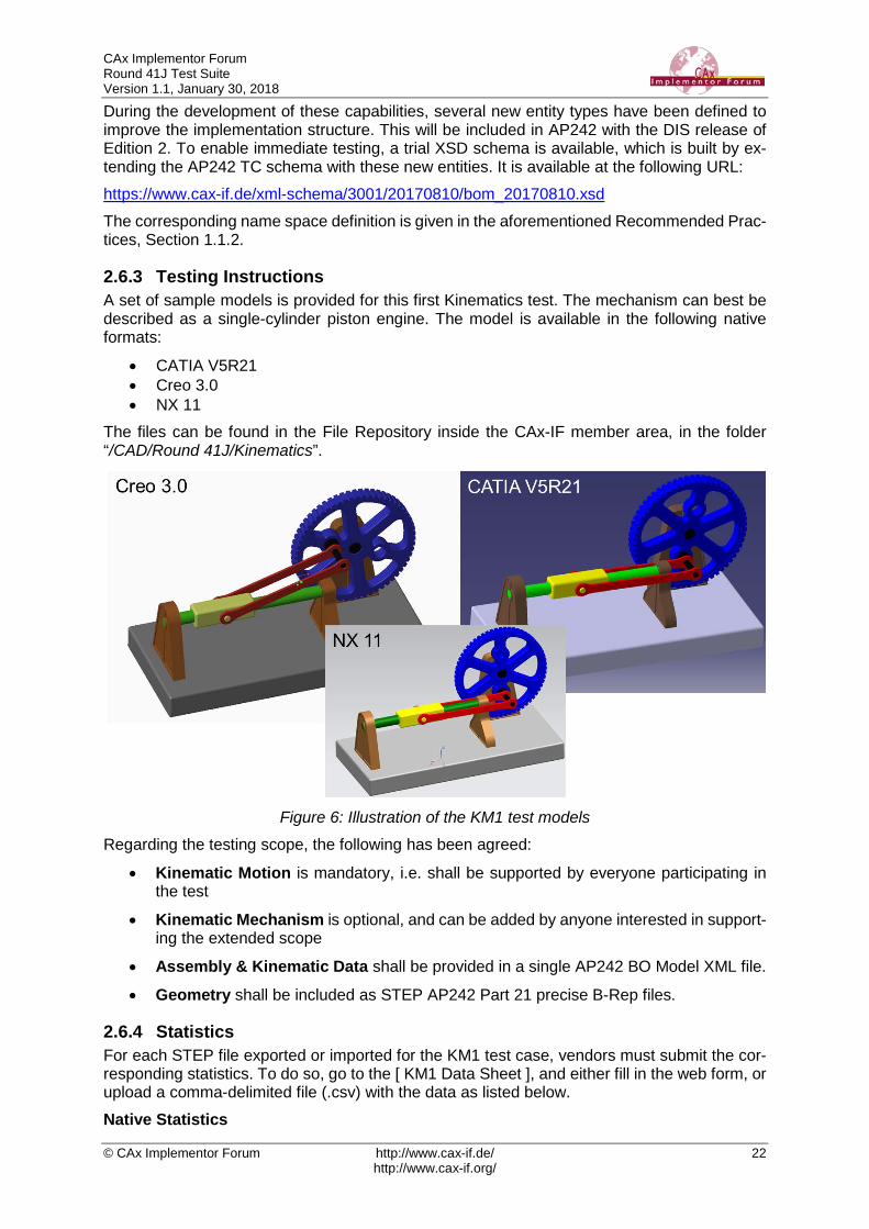
2.6.3 Testing Instructions A set of sample models is provided for this first Kinematics test. The mechanism can best be described as a single-cylinder piston engine. The model is available in the following native formats:
• CATIA V5R21 • Creo 3.0 • NX 11
The files can be found in the File Repository inside the CAx-IF member area, in the folder “/CAD/Round 41J/Kinematics”.
Figure 6: Illustration of the KM1 test models
Regarding the testing scope, the following has been agreed:
• Kinematic Motion is mandatory, i.e. shall be supported by everyone participating in the test
• Kinematic Mechanism is optional, and can be added by anyone interested in support-ing the extended scope
• Assembly & Kinematic Data shall be provided in a single AP242 BO Model XML file.
• Geometry shall be included as STEP AP242 Part 21 precise B-Rep files.
2.6.4 Statistics For each STEP file exported or imported for the KM1 test case, vendors must submit the cor-responding statistics. To do so, go to the [ KM1 Data Sheet ], and either fill in the web form, or upload a comma-delimited file (.csv) with the data as listed below. Native Statistics
CAx Implementor Forum Round 41J Test Suite Version 1.1, January 30, 2018
© CAx Implementor Forum http://www.cax-if.de/ 23 http://www.cax-if.org/
When exporting a STEP file, report what data importing systems should expect to find. For numeric statistics, enter the respective value or 'na' if not supported. For other statistics, select 'full support' (i.e. test case and Rec. Pracs. definitions are fulfilled), 'limited support' (meaning the implementation does not meet all criteria and issues may be expected on import), or 'na' if not supported. Target Statistics When importing a file, report the results found after processing the file as described below. Kinematics-specific Statistics For more detailed information about and discussion of in the Kinematics-specific statistics, please refer to section 4.12 of the Kinematics Recommended Practices mentioned above. Data Sheet Columns
column name description model The name of the test model, here 'SM2'
system_n The system code of the CAD system creating the STEP file
system_t The system code of the CAD system importing the STEP file. For native stats, select 'stp'
assem_struct pass/fail - if the model structure (assembly tree) was transferred correctly, i.e. no nodes have been added or removed, and all ele-ments are on the correct hierarchical level.
kin_motions The number of Kinematic Motions defined in the model
kin_motion_paths The number of paths defined for a Kinematic Motion
kin_mechanisms The number of Kinematic Mechanisms defined in the model
kin_mech_pairs The number of low/high order Kinematic Pairs defined for a Kine-matic Mechanism
kin_mech_acts The number of Kinematic Pairs that have a non-zero value in the attribute ‘actuation’, i.e. where an initial movement can occur
date The date when the statistics were last updated (will be filled in au-tomatically)
issues A short statement on issues with the file
2.7 Test Case CO2: Composite Materials (Ply Contour) All information about this test case can also be viewed in CAESAR on its Information page.
2.7.1 Motivation For several years, some STEP composite interfaces have been available in several CAD tools such as CATIA V5, FiberSIM and in CT CoreTechnologie tools, with a certain level of maturity proven by LOTAR pilot projects. The goal of including Composite Materials in a CAx-IF test round is to align these implemen-tations and provide an official framework for composite materials implementation tests as STEP AP 242e1 since it includes this capability.
2.7.2 Approach The scope of this test case is the “exact implicit” representation of composites where the ply geometry is based on surfaces and contours. “Basic” composite validation properties at the part level are also in the scope of this test case. The approximate explicit representation of composite plies, where there is a 3D tessellated solid for each ply, is out of scope for this test case.

CAx Implementor Forum Round 41J Test Suite Version 1.1, January 30, 2018
© CAx Implementor Forum http://www.cax-if.de/ 24 http://www.cax-if.org/
The approach is to export and to import composite information in STEP AP242 based on the:
• AP242 Edition 1 MIM Longform EXPRESS Schema with Composite Patch
• Recommended Practices for Composite Materials; Version 3.4; June 13, 2017
• Draft Recommended Practices for Composite Structure Validation Properties; Release 0.9; June 8, 2017
The documents are available in the member area of the CAx-IF homepages, under “Infor-mation on Round 40J of Testing”. As the validation properties recommended practices have not been completely agreed upon, some tests will be done by end user checks.
2.7.3 Testing Instructions One test model will be used. The model has been provided by Airbus Helicopter. The test case CPD_PUBLIC_LOTAR.CATPart will be used:
Figure 7: Illustration of the CO2 Test Case
The test case is available in the member area of the CAx-IF homepages, under “Information on Round 40J of Testing”.
2.7.4 Statistics For each STEP file exported or imported for the CO2 test case, vendors must submit the cor-responding statistics. To do so, go to the [ CO2 Data Sheet ], and either fill in the web form, or upload a comma-delimited file (.csv) with the data as listed below. Native Statistics When exporting a STEP file, report what data importing systems should expect to find. For numeric statistics, enter the respective value or 'na' if not supported. For other statistics, select either 'full support' (i.e. test case and Rec. Pracs. definitions are fulfilled), 'limited support' (meaning the implementation does not meet all criteria and issues may be expected on import), or 'na' if not supported. Target Statistics When importing a file, report the results found after processing the file as described below: Ply-related Statistics

CAx Implementor Forum Round 41J Test Suite Version 1.1, January 30, 2018
© CAx Implementor Forum http://www.cax-if.de/ 25 http://www.cax-if.org/
Several of the Statistics for this test case are related to a specific ply within a specific sequence (e.g., material, orientation, rosette). The statistics cannot evaluate this for all plies in the model. Hence, the idea is to select one specific (interesting) sequence and ply on export, and to pub-lish its name in the "Composite Ply Sequence" field of the statistics. Then, fill in the other ply-related statistics with the values as valid for this particular sequence and ply. After import, select the sequence and ply with the name given in the native statistics, and again provide the values valid for this particular sequence and ply. The sequence and ply to be used for evaluating the CO3 test case in Round 40J is:
PLY SC-0035 of SEQUENCE A035
Statistics for Core Sample Point The position of the point for the Core Sample shall be given for:
CORE SAMPLE CS1
Statistics for Flatten Pattern The length of the curve contour of the flatten pattern shall be given for:
PLY SC0200 of SEQUENCE C010
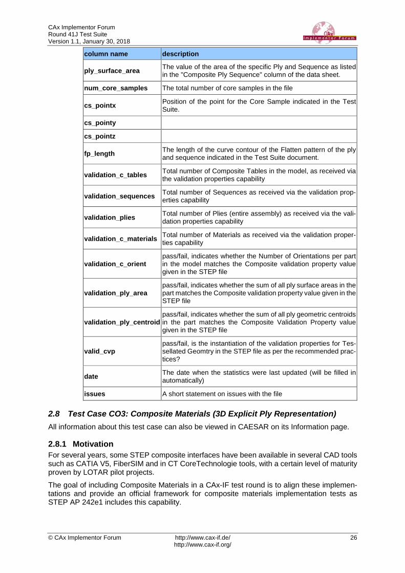
Data Sheet Columns These statistics will be enhanced in future test rounds, especially with the release of newer versions of the Recommended Practices for Composite Structure Validation Properties.
column name description
model The name of the test model, here 'CO3'
system_n The system code of the CAD system creating the STEP file
system_t The system code of the CAD system importing the STEP file. For native stats, select 'stp'
unit The unit the model is designed in
compos_tables The number of Composite Tables in the Model
sequences The number of Sequences in the model
plies The total number of plies in the file
num_materials Total number of Materials defined
compos_table_name The name of the Composite Table of the model
ply_sequence The ID of the Sequence and the ID of the Ply within that Se-quence for all ply-related statistics; e.g., "Ply.P4 of Se-quence.S4".
seq_ply_number The total number of Plies defined within the Sequence as listed in the "Composite Ply Sequence" column of the data sheet.
seq_ply_material The name of the Material of the specific Ply and Sequence as listed in the "Composite Ply Sequence" column of the data sheet.
seq_ply_mat_type The type of Material of the specific Ply and Sequence as listed in the "Composite Ply Sequence" column of the data sheet.
seq_ply_orient pass/fail - whether the orientation of the specific Ply and Se-quence as listed in the "Composite Ply Sequence" column of the data sheet was correct
seq_ply_rosette The name of the Rosette of the specific Ply and Sequence as listed in the "Composite Ply Sequence" column of the data sheet.
CAx Implementor Forum Round 41J Test Suite Version 1.1, January 30, 2018
© CAx Implementor Forum http://www.cax-if.de/ 26 http://www.cax-if.org/
column name description
ply_surface_area The value of the area of the specific Ply and Sequence as listed in the "Composite Ply Sequence" column of the data sheet.
num_core_samples The total number of core samples in the file
cs_pointx Position of the point for the Core Sample indicated in the Test Suite.
cs_pointy
cs_pointz
fp_length The length of the curve contour of the Flatten pattern of the ply and sequence indicated in the Test Suite document.
validation_c_tables Total number of Composite Tables in the model, as received via the validation properties capability
validation_sequences Total number of Sequences as received via the validation prop-erties capability
validation_plies Total number of Plies (entire assembly) as received via the vali-dation properties capability
validation_c_materials Total number of Materials as received via the validation proper-ties capability
validation_c_orient pass/fail, indicates whether the Number of Orientations per part in the model matches the Composite validation property value given in the STEP file
validation_ply_area pass/fail, indicates whether the sum of all ply surface areas in the part matches the Composite validation property value given in the STEP file
validation_ply_centroid pass/fail, indicates whether the sum of all ply geometric centroids in the part matches the Composite Validation Property value given in the STEP file
valid_cvp pass/fail, is the instantiation of the validation properties for Tes-sellated Geomtry in the STEP file as per the recommended prac-tices?
date The date when the statistics were last updated (will be filled in automatically)
issues A short statement on issues with the file
2.8 Test Case CO3: Composite Materials (3D Explicit Ply Representation) All information about this test case can also be viewed in CAESAR on its Information page.
2.8.1 Motivation For several years, some STEP composite interfaces have been available in several CAD tools such as CATIA V5, FiberSIM and in CT CoreTechnologie tools, with a certain level of maturity proven by LOTAR pilot projects. The goal of including Composite Materials in a CAx-IF test round is to align these implemen-tations and provide an official framework for composite materials implementation tests as STEP AP 242e1 includes this capability.

CAx Implementor Forum Round 41J Test Suite Version 1.1, January 30, 2018
© CAx Implementor Forum http://www.cax-if.de/ 27 http://www.cax-if.org/
2.8.2 Approach The scope of this test case is the “3D tessellated” representation for each ply. The approximate explicit representation of composite plies includes a 3D tessellated solid for each ply. The approach is to export and import the composite information in STEP AP242 based on the Recommended Practices for Composite Materials; Version 3.4; June 13, 2017. The document is available in the member area of the CAx-IF homepages, under “Information on Round 40J of Testing”. Implementation requires using the “AP242 Edition 1 MIM Longform EXPRESS Schema with Composite Patch”, which is available in the same location. Refer to Annex C for further information on the extended data model. As the validation properties recommended practices have not been completely agreed upon, the tests will be done by end user checks.
2.8.3 Testing Instructions One test model will be used. The model has been provided by The Boeing Company. The test case ASME_Y14.37_RosetteType2.CATPart will be used:
Figure 8: Illustration of the CO3 Test Case
The test model contains the 3D tessellated representation of each ply. The test case is available in the member area of the CAx-IF homepages, under “Information on Round 40J of Testing”.
2.8.4 Statistics For each STEP file exported or imported for the CO3 test case, vendors must submit the cor-responding statistics. To do so, go to the [ CO3 Data Sheet ], and either fill in the web form, or upload a comma-delimited file (.csv) with the data as listed below. Native Statistics When exporting a STEP file, report what data importing systems should expect to find. For numeric statistics, enter the respective value or 'na' if not supported. For other statistics, select either 'full support' (i.e. test case and Rec. Pracs. definitions are fulfilled), 'limited support' (meaning the implementation does not meet all criteria and issues may be expected on import), or 'na' if not supported. Target Statistics
CAx Implementor Forum Round 41J Test Suite Version 1.1, January 30, 2018
© CAx Implementor Forum http://www.cax-if.de/ 28 http://www.cax-if.org/
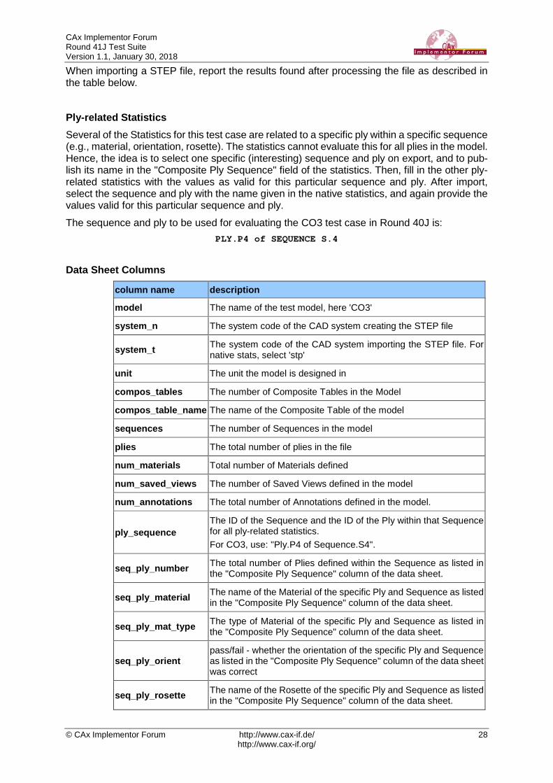
When importing a STEP file, report the results found after processing the file as described in the table below. Ply-related Statistics Several of the Statistics for this test case are related to a specific ply within a specific sequence (e.g., material, orientation, rosette). The statistics cannot evaluate this for all plies in the model. Hence, the idea is to select one specific (interesting) sequence and ply on export, and to pub-lish its name in the "Composite Ply Sequence" field of the statistics. Then, fill in the other ply-related statistics with the values as valid for this particular sequence and ply. After import, select the sequence and ply with the name given in the native statistics, and again provide the values valid for this particular sequence and ply. The sequence and ply to be used for evaluating the CO3 test case in Round 40J is:
PLY.P4 of SEQUENCE S.4
Data Sheet Columns
column name description
model The name of the test model, here 'CO3'
system_n The system code of the CAD system creating the STEP file
system_t The system code of the CAD system importing the STEP file. For native stats, select 'stp'
unit The unit the model is designed in
compos_tables The number of Composite Tables in the Model
compos_table_name The name of the Composite Table of the model
sequences The number of Sequences in the model
plies The total number of plies in the file
num_materials Total number of Materials defined
num_saved_views The number of Saved Views defined in the model
num_annotations The total number of Annotations defined in the model.
ply_sequence The ID of the Sequence and the ID of the Ply within that Sequence for all ply-related statistics. For CO3, use: "Ply.P4 of Sequence.S4".
seq_ply_number The total number of Plies defined within the Sequence as listed in the "Composite Ply Sequence" column of the data sheet.
seq_ply_material The name of the Material of the specific Ply and Sequence as listed in the "Composite Ply Sequence" column of the data sheet.
seq_ply_mat_type The type of Material of the specific Ply and Sequence as listed in the "Composite Ply Sequence" column of the data sheet.
seq_ply_orient pass/fail - whether the orientation of the specific Ply and Sequence as listed in the "Composite Ply Sequence" column of the data sheet was correct
seq_ply_rosette The name of the Rosette of the specific Ply and Sequence as listed in the "Composite Ply Sequence" column of the data sheet.
CAx Implementor Forum Round 41J Test Suite Version 1.1, January 30, 2018
© CAx Implementor Forum http://www.cax-if.de/ 29 http://www.cax-if.org/
column name description
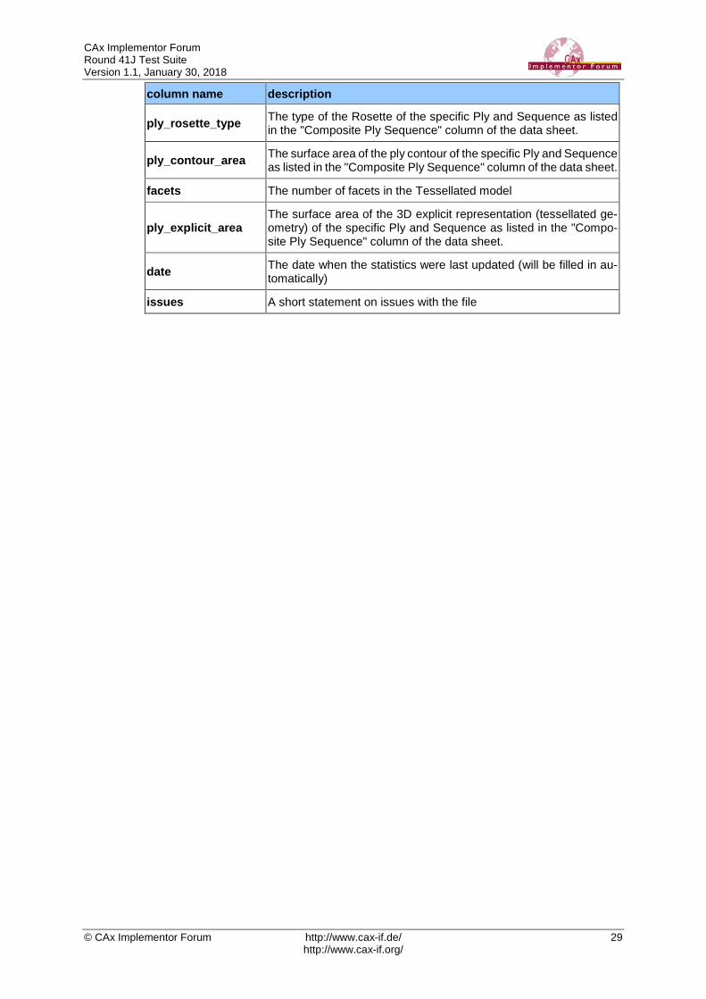
ply_rosette_type The type of the Rosette of the specific Ply and Sequence as listed in the "Composite Ply Sequence" column of the data sheet.
ply_contour_area The surface area of the ply contour of the specific Ply and Sequence as listed in the "Composite Ply Sequence" column of the data sheet.
facets The number of facets in the Tessellated model
ply_explicit_area The surface area of the 3D explicit representation (tessellated ge-ometry) of the specific Ply and Sequence as listed in the "Compo-site Ply Sequence" column of the data sheet.
date The date when the statistics were last updated (will be filled in au-tomatically)
issues A short statement on issues with the file
CAx Implementor Forum Round 41J Test Suite Version 1.1, January 30, 2018
© CAx Implementor Forum http://www.cax-if.de/ 30 http://www.cax-if.org/
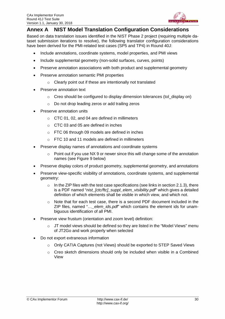
Annex A NIST Model Translation Configuration Considerations Based on data translation issues identified in the NIST Phase 2 project (requiring multiple da-taset submission iterations to resolve), the following translator configuration considerations have been derived for the PMI-related test cases (SP5 and TP4) in Round 40J:
• Include annotations, coordinate systems, model properties, and PMI views
• Include supplemental geometry (non-solid surfaces, curves, points)
• Preserve annotation associations with both product and supplemental geometry
• Preserve annotation semantic PMI properties o Clearly point out if these are intentionally not translated
• Preserve annotation text o Creo should be configured to display dimension tolerances (tol_display on) o Do not drop leading zeros or add trailing zeros
• Preserve annotation units o CTC 01, 02, and 04 are defined in millimeters o CTC 03 and 05 are defined in inches o FTC 06 through 09 models are defined in inches o FTC 10 and 11 models are defined in millimeters
• Preserve display names of annotations and coordinate systems o Point out if you use NX 9 or newer since this will change some of the annotation
names (see Figure 9 below)
• Preserve display colors of product geometry, supplemental geometry, and annotations
• Preserve view-specific visibility of annotations, coordinate systems, and supplemental geometry:
o In the ZIP files with the test case specifications (see links in section 2.1.3), there is a PDF named “nist_[ctc/ftc]_suppl_elem_visibility.pdf” which gives a detailed definition of which elements shall be visible in which view, and which not.
o Note that for each test case, there is a second PDF document included in the ZIP files, named “…_elem_ids.pdf” which contains the element ids for unam-biguous identification of all PMI.
• Preserve view frustum (orientation and zoom level) definition: o JT model views should be defined so they are listed in the “Model Views” menu
of JT2Go and work properly when selected
• Do not export extraneous information o Only CATIA Captures (not Views) should be exported to STEP Saved Views o Creo sketch dimensions should only be included when visible in a Combined
View

CAx Implementor Forum Round 41J Test Suite Version 1.1, January 30, 2018
© CAx Implementor Forum http://www.cax-if.de/ 31 http://www.cax-if.org/
Figure 9: NX 8 vs. NX 9 Dimension Display Names

CAx Implementor Forum Round 41J Test Suite Version 1.1, January 30, 2018
© CAx Implementor Forum http://www.cax-if.de/ 32 http://www.cax-if.org/
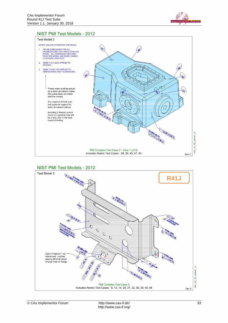
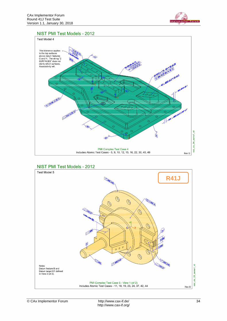
Annex B NIST Model Definitions This section provides an overview of the test models used for testing of PMI capabilities in Round 41J, namely SP5 (see section 2.1) and TGP3 (see section 2.2). All of these models have been developed in the course of NIST’s “MBE PMI Validation and Conformance Testing Project”. Information on this project and related activities can be found on internet at https://pages.nist.gov/CAD-PMI-Testing/ The full suite of models consists of two data sets: First, the so-called Complex Text Cases (CTC). These are the models with indices 01-05. They contain a collection of basic PMI constructs. Download the definitions from: https://s3.amazonaws.com/nist-el/mfg_digitalthread/NIST_CTC_Definitions_Dec_2016.zip
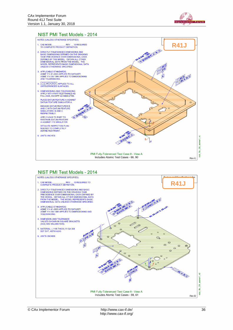
Second, the so-called Fully-toleranced Test Cases (FTC). These are the models with indices 06-11. They are fully defined models, providing all information required to actually manufacture and inspect the models. Download the definitions from: https://s3.amazonaws.com/nist-el/mfg_digitalthread/NIST_FTC_Definitions_Dec_2016.zip
In order to reduce the workload for the participating vendors, not all eleven models shall be tested in Round 41J. The following five models have chosen:
• CTC 3 & 4
• FTC 6, 8 & 9 This selection still covers a wide range of PMI elements, while reducing the number of ex-changed to be done for each interface vendor. The models are indicated with a label below. The illustrations below show the first page of the PDF document for each test model.
CAx Implementor Forum Round 41J Test Suite Version 1.1, January 30, 2018
© CAx Implementor Forum http://www.cax-if.de/ 33 http://www.cax-if.org/
R41J
CAx Implementor Forum Round 41J Test Suite Version 1.1, January 30, 2018
© CAx Implementor Forum http://www.cax-if.de/ 34 http://www.cax-if.org/
R41J

CAx Implementor Forum Round 41J Test Suite Version 1.1, January 30, 2018
© CAx Implementor Forum http://www.cax-if.de/ 35 http://www.cax-if.org/
R41J
CAx Implementor Forum Round 41J Test Suite Version 1.1, January 30, 2018
© CAx Implementor Forum http://www.cax-if.de/ 36 http://www.cax-if.org/
R41J
R41J

CAx Implementor Forum Round 41J Test Suite Version 1.1, January 30, 2018
© CAx Implementor Forum http://www.cax-if.de/ 37 http://www.cax-if.org/
CAx Implementor Forum Round 41J Test Suite Version 1.1, January 30, 2018
© CAx Implementor Forum http://www.cax-if.de/ 38 http://www.cax-if.org/
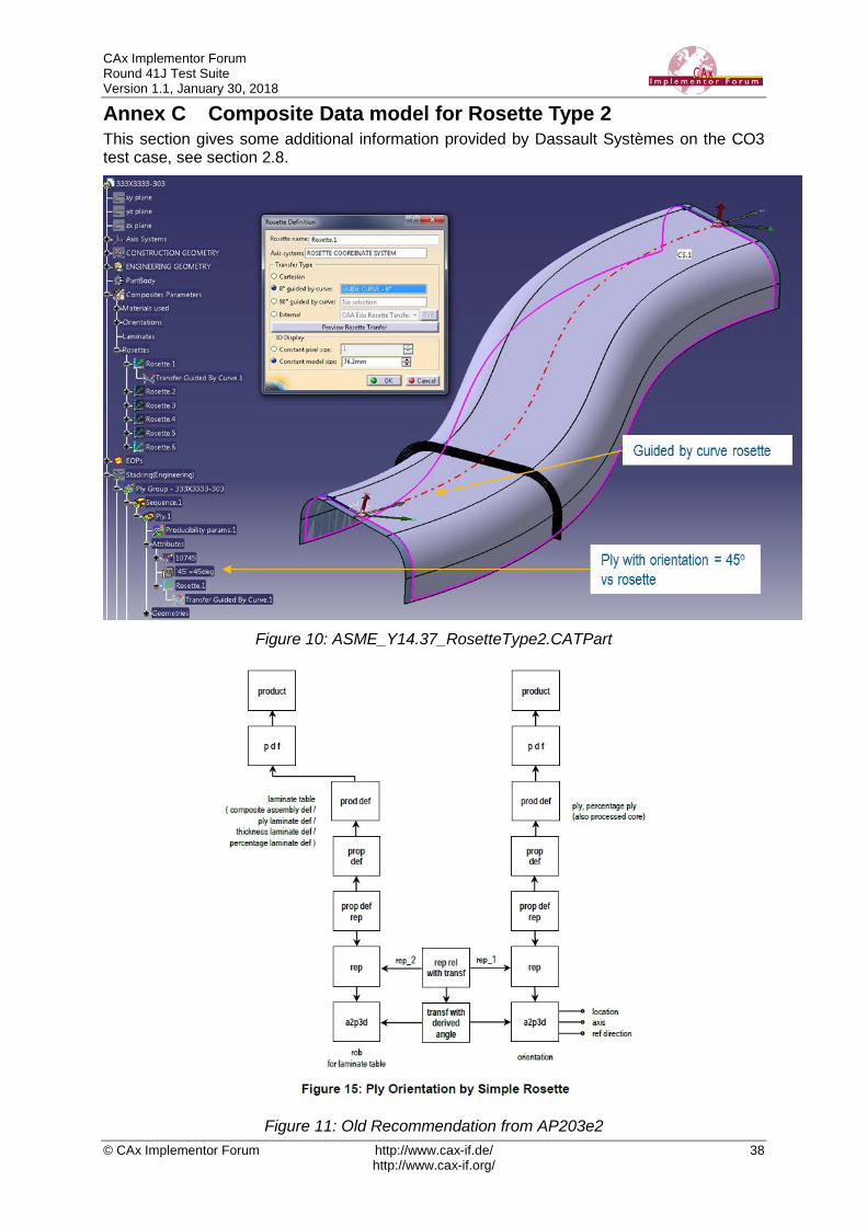
Annex C Composite Data model for Rosette Type 2 This section gives some additional information provided by Dassault Systèmes on the CO3 test case, see section 2.8.
Figure 10: ASME_Y14.37_RosetteType2.CATPart
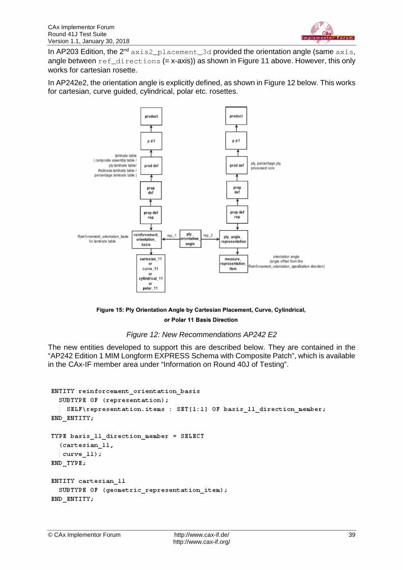
Figure 11: Old Recommendation from AP203e2
CAx Implementor Forum Round 41J Test Suite Version 1.1, January 30, 2018
© CAx Implementor Forum http://www.cax-if.de/ 39 http://www.cax-if.org/
In AP203 Edition, the 2nd axis2_placement_3d provided the orientation angle (same axis, angle between ref_directions (= x-axis)) as shown in Figure 11 above. However, this only works for cartesian rosette. In AP242e2, the orientation angle is explicitly defined, as shown in Figure 12 below. This works for cartesian, curve guided, cylindrical, polar etc. rosettes.
Figure 12: New Recommendations AP242 E2
The new entities developed to support this are described below. They are contained in the “AP242 Edition 1 MIM Longform EXPRESS Schema with Composite Patch”, which is available in the CAx-IF member area under “Information on Round 40J of Testing”.
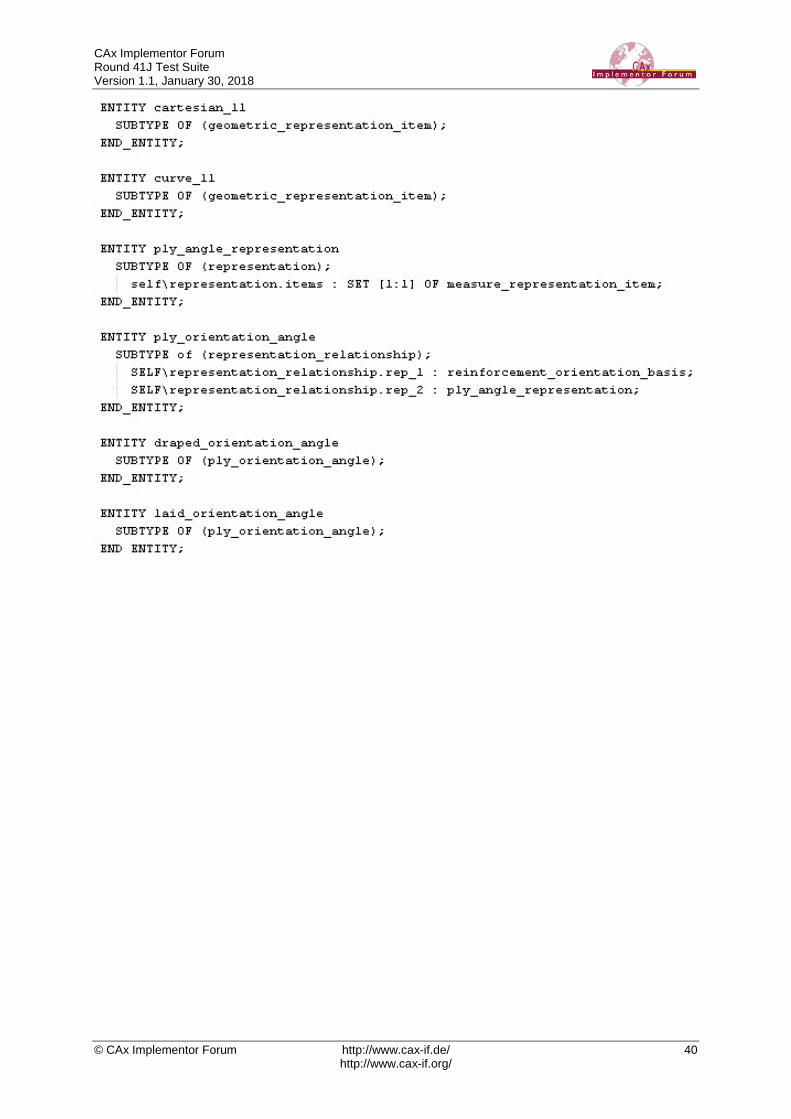
CAx Implementor Forum Round 41J Test Suite Version 1.1, January 30, 2018
© CAx Implementor Forum http://www.cax-if.de/ 40 http://www.cax-if.org/