Embed Size (px)
Citation preview
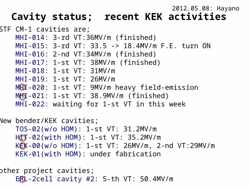
Cavity status; recent KEK activities2012.05.08: Hayano
(1) STF CM-1 cavities are; MHI-014: 3-rd VT:36MV/m (finished) MHI-015: 3-rd VT: 33.5 -> 18.4MV/m F.E. turn ON MHI-016: 2-nd VT:34MV/m (finished) MHI-017: 1-st VT: 38MV/m (finished) MHI-018: 1-st VT: 31MV/m MHI-019: 1-st VT: 26MV/m MHI-020: 1-st VT: 9MV/m heavy field-emission MHI-021: 1-st VT: 38.9MV/m (finished) MHI-022: waiting for 1-st VT in this week
(2) New bender/KEK cavities; TOS-02(w/o HOM): 1-st VT: 31.2MV/m HIT-02(with HOM): 1-st VT: 35.2MV/m KEK-00(w/o HOM): 1-st VT: 26MV/m, 2-nd VT:29MV/m KEK-01(with HOM): under fabrication
(3) other project cavities; ERL-2cell cavity #2: 5-th VT: 50.4MV/m

ERL 2-cell cavity #2 5-th VT
Detail report in the end of slides
March 6

MHI-020 1-st VT
heavy field emission input RF cable break happened!
March 15
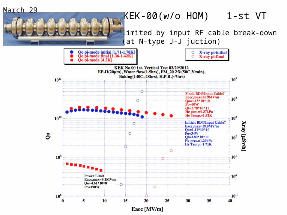
KEK-00(w/o HOM) 1-st VTMarch 29
limited by input RF cable break-down (at N-type J-J juction)

KEK-00(w/o HOM) 2-nd VTApril 5
limited by cell#2 defects, other cells were over 40MV/m

MHI-021 1-st VTApril 12
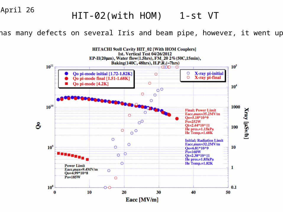
HIT-02(with HOM) 1-st VTApril 26
It has many defects on several Iris and beam pipe, however, it went up 35MV/m.

8
History and Recent result of cERL 2-cell cavity #2
K. Watanabe (KEK)
May/2012

9
Log
Mar/2009: Fabrication cavity by MHI
July/2009: Bulk EP (5 + 100 um) and Annealing
Feb/2010: Light EP (20 um) and 1st VT
April/2010: Light EP (20 um)
and 2nd VT with HOM pick-up (Type 0 Normal)
July/2010: Light EP (20 um)
Aug/2010: 3rd VT with HOM pick-up (Type 0 Normal)
Sep/2010: Light EP (20 um)
Oct/2010: 4th VT with HOM pick-up (Type 0 Normal)
Feb/2012: Light EP (5um)
Mar/2012: 5th VT with HOM pick-up (Type 2)
•1st VT: to check the cavity performance (quality check).
•2nd ~ 5th VT: to study a performance of HOM coupler
and HOM pick-ups.
Measurement of sustainable field without
quench at HOM coupler at CW
The field was raised to a rf power limit
or heating limit of HOM pick-ups.
cERL injector 2-cell cavity #2 (Proto-type model)
(With two input coupler port and five loop-type HOM couplers)
Target Gradient is 15 MV/m at CW in Cryomodule.
* Cavity design by E. Kako
* HOM coupler and feed-through design by K. Watanabe
* Optical Inspection was done after each treatment.
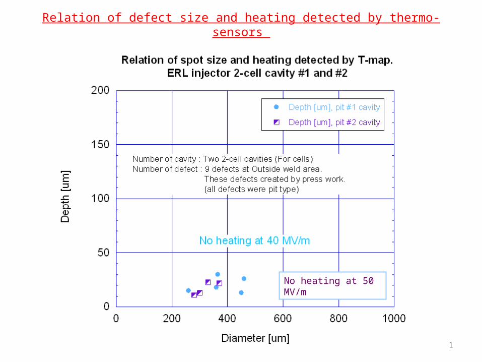
Few defects found at Outside weld area.
These defects created by press work.
On the weld area, there are no welding defect.
* The LLRF measurement, HOM study, RF tuning, optical inspection, preparation part, assembly work and VT were done by K. Watanabe with few Technicians.
total EP removal =190µm

10
Example: Optical Inspection result (After 1st VT)
Four pit type defect found at Outside weld area.
(defects created by press work)
On the EBW seam, there were no welding defect.
11
Relation of defect size and heating detected by thermo-sensors
No heating at 50 MV/m
12
106
107
108
109
1010
1011
1
10
100
1000
104
105
0 10 20 30 40 50 60
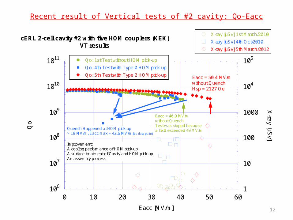
cERL 2-cell cavity #2 with five HOM couplers (KEK)VT results
Qo: 1st Test without HOM pick-up
Qo: 4th Test with Type 0 HOM pick-up
Qo: 5th Test with Type 2 HOM pick-up
X-ray [uSv] 1st March/2010
X-ray [uSv] 4th Oct/2010
X-ray [uSv] 5th March/2012
Qo
X-ray [uS
v]
Eacc [MV/m]
Eacc = 50.4 MV/mwithout QuenchHsp = 2127 Oe
Eacc = 40.9 MV/mwithout QuenchTest was stoppd becausea field exceeded 40 MV/mQuench Happened at HOM pick-up
> 18 MV/m, Eacc max = 42.6 MV/m (No data point)
Improvement: A cooling performance of HOM pick-upA surface treatment of Cavity and HOM pick-upAn assembly process
Recent result of Vertical tests of #2 cavity: Qo-Eacc

13
cERL 2-cell (KEK) 9-cell TESLA-like
Frequency 1300 MHz 1300 MHz
R/Q 204.0 1016
G 287.8 277
Esp/Eacc 2.25 2.17
Hsp/Eacc[Oe/MV/m]
42.2 41.0
K (coupling) 1.94 2.0
L (effec.) 0.23 m/cavity ---
Iris diameter.BP diameter.
70 mm88 mm
70 mm80 mm
Other Hsp on Equator50 MV/m→2110 Oe
Hsp on Equator45 MV/m→1845 Oe
Cavity Parameters of 2-cell injector and 9-cell cavity
Calculated by E. Kako (by Superfish)

14
Max Eacc and Cause of limitation Other
1st VTMar/2010
40.9 MV/m without Quench.The test was stopped because a field exceeded 40MV/m.
Removed material = 125 um
2nd VTApril/2010
Vacuum leak happened during 2K high field measurement, then the test was stopped. No quench at 14 MV/m in Liq He……….Leak location was one ICT 70 flange (Low temperature side).
Removed material = 145 um
With HOM pick-up(Type 0 Normal, gap = 0.5 mm)
3rd VTAug/2010
38.6 MV/m with Quench at HOM pick-up.Sustainable field : 12 MV/m outside liq. He
17.4 MV/m in liq. He
Cause of limitation was a heating of HOM pick-up.
Removed material = 165 um
With HOM pick-up(Type 0 Normal, gap = 0.5 mm)
4th VTOct/2010
42.6 MV/m with Quench at HOM pick-up.
Sustainable field : 13 MV/m outside liq. He
18.4 MV/m in liq. He
Cause of limitation was a heating of HOM pick-up.
Removed material = 185 um
With HOM pick-up(Type 0 Normal, gap = 2.0 mm)
5th VTMar/2012
50.4 MV/m without Quench and Field Emission (in lig. He). The test was stopped because a field exceeded 50MV/m.(RF power limit)
Hsp on Equator is 2127 Oe.
Removed material = 190 um
With HOM pick-up(Type 2, gap = 2.0 mm)
Result of Vertical tests of #2 cavity: History and Summary

15
Surface treatment
No. Amount EP [um]Current density
1st water rinsing
rinse HPR [hour] Other
Bulk EP 5 + 100 Idle: 5 minCase 1
none 2 ---
Light EP1st
2026-30 mA/cm2
Idle: 20 minCase 2
FM-20 and HOT Bathwith Ultra-sonic
(1 hour + 1 hour)
2.5+
2.5 (with Flange)
In coated Helicoflex100 C Baking
Light EP2nd
2024-30 mA/cm2
Idle: 20 minCase 2
FM-20 and HOT Bathwith Ultra-sonic
(1 hour + 1 hour)
2.5+
2.5 (with Flange)
In coated Helicoflex100 C Baking
Light EP3rd
2030-40 mA/cm2
Idle: 20 minCase 2
FM-20 with Ultra-sonic (2 hours) 2.5+
2.5 (with Flange)
In coated Helicoflex100 C Baking
Light EP4th
2030-40 mA/cm2
Idle: 20 minCase 2
FM-20 with Ultra-sonic (2 hours) 2.5+
2.5 (with Flange)
In coated Helicoflex100 C Baking
Light EP5th
537-38 mA/cm2
Idle: 30 min Case 3
End Group cleaning by Brush.FM-20 with Ultra-sonic (30 min)
End Group cleaning again by Brush.
4+
2 (with Flange)
Sn coated Helicoflex120 C Baking
Process of 1st water rinsing
* Case 1: Water supply flow (4 min) -> Pump off (2 min) : Repeat this cycle (total 40 min)
* Case 2: Water supply flow (3 min) -> Pump off (1 min) : Repeat this cycle (total 90 min)
* Case 3: water fill-and-close (40 min), water supply flow 20min, and with cavity rotation 40min : total 100min

16
Preparation of HOM pick-up (1): Surface Treatment and Cleaning Method
No. Type Treatment Cleaning Method after CP
1st VT Without
2nd VT Type 0 Feedthrough: only FM-20 with Ultra-sonic Niobium antenna: Chemical polishing (without mechanical polish)
FM-20 with Ultra-sonic ~ 10 min.
3rd VT Type 0 Feedthrough: only FM-20 with Ultra-sonic Niobium antenna: Chemical polishing (without mechanical polish)
FM-20 with Ultra-sonic ~ 10 min.
4th VT Type 0 Feedthrough: only FM-20 with Ultra-sonicNiobium antenna: Chemical polishing (without mechanical polish)
FM-20 with Ultra-sonic ~ 10 min.
5th VT Type 2 Remove a brazing material near Joint point between inner conductor and niobium antenna.Mechanical polishing on niobium antenna after fabrication (mirror finish).Chemical polishing on niobium part (Total: 5 min).
After CP,FM-20 with Ultra-sonic ~ 20 min.Washing by sponge with FM-20.
Dry at Class 10.
17
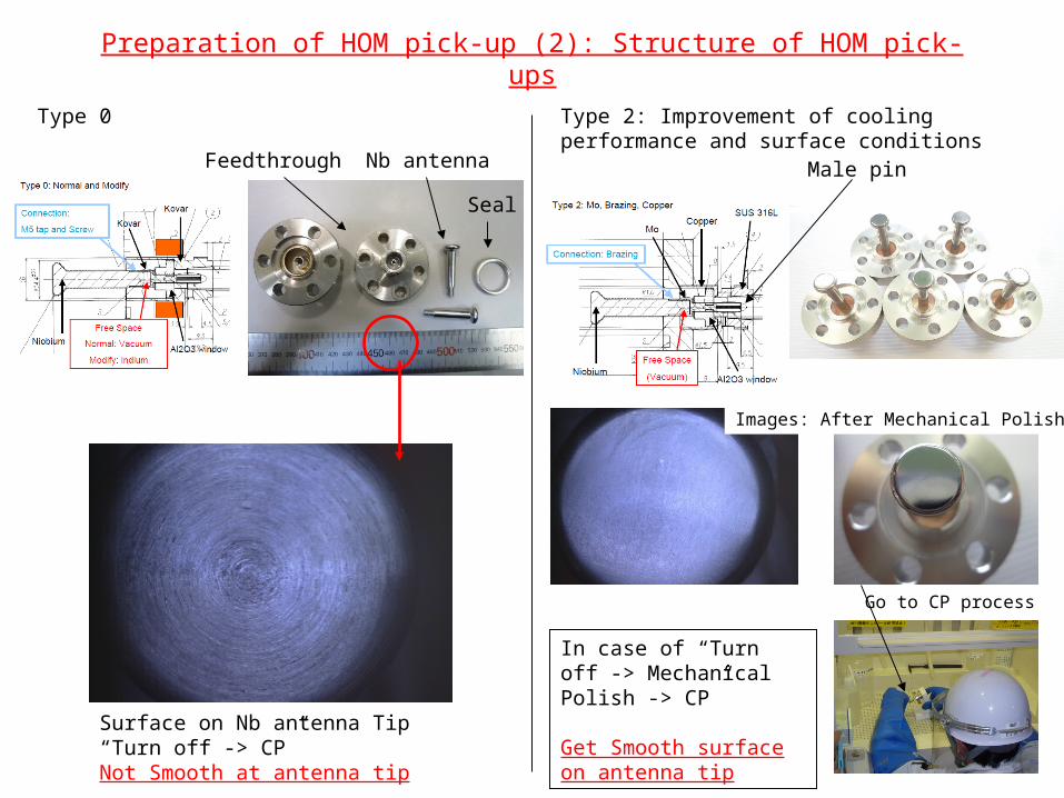
Preparation of HOM pick-up (2): Structure of HOM pick-ups
Type 0 Type 2: Improvement of cooling performance and surface conditions
Seal
Nb antennaFeedthrough
Surface on Nb antenna Tip“Turn off -> CP”Not Smooth at antenna tip
In case of “Turn off -> Mechanical Polish -> CP”
Get Smooth surface on antenna tip
Male pin
Images: After Mechanical Polish
Go to CP process

18
About 5th VT of #2 cavity
19
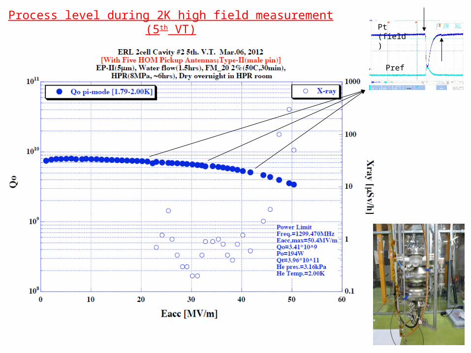
Process level during 2K high field measurement (5th VT) Pt (field)
Pref

20
Frequency and Qext change during cooldown (5th VT)
Tuning of HOM couplers for accelerating mode was very well.
Resonant Frequency at Room temp (vacuum). is 1297.685 MHz.

21
Lorentz force detuning (5th VT)
22
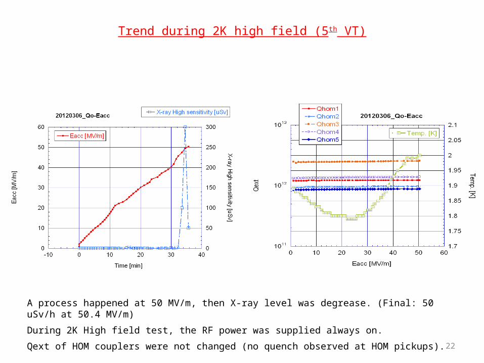
Trend during 2K high field (5th VT)
A process happened at 50 MV/m, then X-ray level was degrease. (Final: 50 uSv/h at 50.4 MV/m)
During 2K High field test, the RF power was supplied always on.
Qext of HOM couplers were not changed (no quench observed at HOM pickups).

23
Reference of world record of Hsp on Equator