Embed Size (px)
Citation preview

Cavity Integration summary
H. HayanoApril 25, 2008 ILC-SCRF meeting @FNAL

• Tuner performance• Tuner Motor location• Tuner specification profile table• Input coupler industrialization• Input coupler tunability• Input coupler specification profile table• ‘S1 Global’ issues
Followings were discussed

• Lorentz detuning simulation (Y. Yamamoto) discussion: need more clear discussion why we need stiff tuner,
cost of stiff vs. cost of robust piezo?
• Ball-screw tuner performance results (T. Saeki) preliminary report on LD compensation, dø/dt detuning measurement,
microphonics, etc.
• Blade tuner update (C. Pagani) version 3 blade tuner tested at DESY, BESSY. 8 unit will be delivered
to FNAL in May.
• Comment on tuner motor reliability (S. Noguchi) discussion: difficult to estimate MTBF,
need to compare benefit of motor outside vs. risk increase like vac leak.
repaireble with minimum cost (with minimum design change and minimum risk ) should be consensus.
Tuner performance
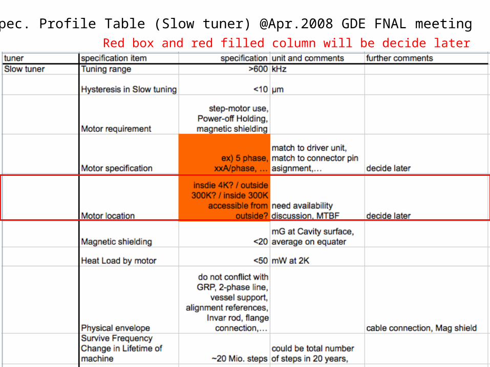
Spec. Profile Table (Slow tuner) @Apr.2008 GDE FNAL meeting
Red box and red filled column will be decide later

Spec. Profile Table (Fast tuner) @Apr.2008 GDE FNAL meeting
Red box and red filled column will be decide later

Plan for developing Tuner Work Package
• Finalize spec. profile table, today.• Upload to EDMS team workspace now.• Revise any spec. in any time, if it is inconsistent.
• Develop tuner comparison table and R&D of each tuner for EDR baseline selection.
• Write and develop ‘recommendation of motor/acutuator location’ according to the past presentations and R&D, report it to PM by the next Chicago meeting.
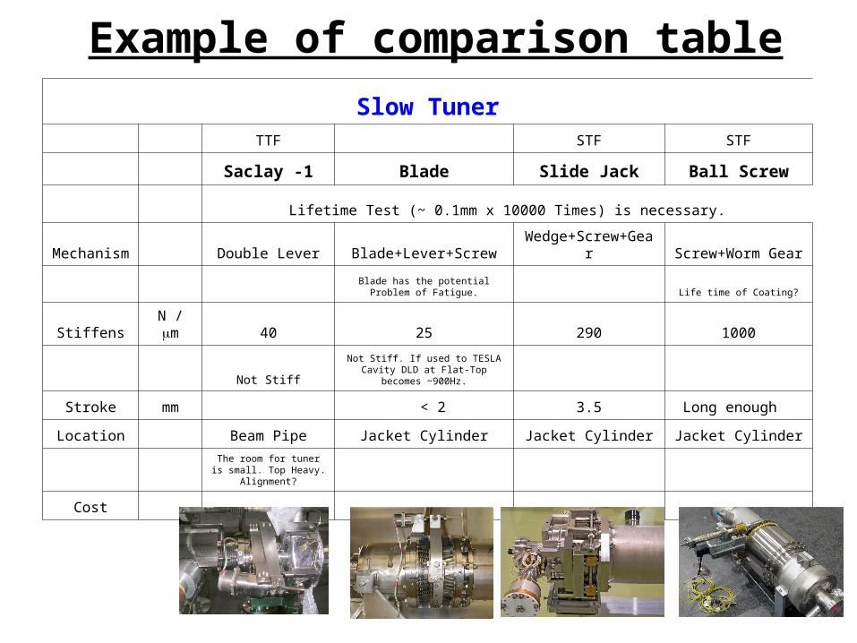
Slow Tuner TTF STF STF
Saclay -1 Blade Slide Jack Ball Screw
Lifetime Test (~ 0.1mm x 10000 Times) is necessary.
Mechanism Double Lever Blade+Lever+Screw Wedge+Screw+Gear Screw+Worm Gear
Blade has the potential Problem of
Fatigue. Life time of Coating?
Stiffens N / m 40 25 290 1000
Not StiffNot Stiff. If used to TESLA Cavity
DLD at Flat-Top becomes ~900Hz.
Stroke mm < 2 3.5 Long enough
Location Beam Pipe Jacket Cylinder Jacket Cylinder Jacket Cylinder
The room for tuner is
small. Top Heavy. Alignment?
Cost
Example of comparison table

Fast Tuner TTF STF STF
Saclay -1 Blade Slide Jack Ball Screw
Piezo(200V) Piezo(200V) Piezo(150V) Piezo+Blade
Speed ? Blade has the potential Problem of
Fatigue. Speed ?
NORIAC (1
Spare)NORIAC (1
Spare)Piezo Mechanic x
1 Piezo Mechanic x 1
Size mm 10 x 10 x 26 10 x 10 x 38 φ20 x 18
Stiffness N / m 105 70 500
Max. Load kN 4 4 14
Stroke:RT m 40 60 20
Stroke:2k m 4 6 2
Compensation m 3.4 6 1
Speed
Delay 0.6 msec.
RepairabilityMotor need Disassemble need Disassemble Outside Poor
Piezo need Disassemble need Disassemble Repairable need Disassemble
US Study on this Subject exists.
How to check Piezos just we install. There are no experience for long term operation in Pulsed mode. Life time Test is necessary.
Cont.

• XFEL coupler (S. Prat) Information on coupler industrialization status, plan, cost, etc.
• Fixed coupler operation (S. Noguchi) grouping cavity concept for maximum E operation with rough cost
comparison.
discussion: gaussian cavity gradient distribution is feasible?
optimistic estimation? Error will be more small.
Cost minimum for matched condition?
Small LLRF margin.
• Variable/Fixed coupler technical issue (E. Kako) Visualized discussion of variable/fixed coupler installation.
Coupler discussion

Spec. Profile Table @Apr.2008 GDE FNAL meeting
Red box and red filled column will be decide later
Yellow box are Revised in this Meeting.

Plan for developing Coupler Work Package
• Finalize spec. profile table, today.• Upload to EDMS team workspace now.• Revise any spec. in any time, if it is inconsistent.
• Develop pros/cons table for tunability.• Write and develop ‘recommendation of
tunability’ according to the past presentations, report it to PM, by the next Chicago meeting.

S1‐Global at KEK STF
(DESY or US) BL#2 BL#5 BL#6>32MV/m 29MV/m ??MV/m ??MV/m
DESY1 DESY2 FNAL1 FNAL2 >32MV/m >32MV/m >32MV/m >32MV/m
S1 Global original concept
( or BL#7?) ( or LL #7? LL#8?)
Module A for BL cavities
Module B for LL cavities
4 KEK-BL cavities
2 DESY cavities + 2 FNAL cavities DESY and FNAL cavities are considered to be assembled in the Module B.
Technical points of S1-Global;1. Two STF cryomodules have different design for STF-BL and LL cavities, respectively.
• Module A cryostat was designed for accommodating four BL cavities, and Module B cryostat for four LL cavities.
2. The helium vessel design of STF-LL cavity has geometrically common concept with DESY and FNAL vessels. The design of STF-BL cavity package has many different points to DESY and FNAL vessels.
3. Proposed combination of different types of cavities for S1-Global, • Module A will consist of 4 BL cavities or 3 BL cavities + 1 LL cavity. • Module B will consist of 2 DESY cavities + 2 FNAL cavities or DESY + FNAL + LL
cavities.

Problem-1: Incompatibility between DESY & FNAL cavity package and STF cavity package
DESY & FNAL Cavity Package STF Cavity PackageInput couplers and LHe supply cross connect pipes of KEK and DESY & FNAL locate in the opposite side with respect to the direction of cavity package

Problem-2:The length of the GRP is not enough for supporting FNAL or DESY cavitieswhen they are installed in STF module.
STF-LL Cavity Package
FNAL Cavity Package

Problem-3: Pipes & support Interference between DESY & FNAL cavity package and STF GRP
1. FNAL LHe supply pipe cross connect and DESY LHe supply pipe support conflict with STF GRP support legs.
2. Locations of support legs and support tabs are not consistent.
LHe supply pipe LHe supply pipe support
Viewed from upper-side
Support legs of GRP

Problem-4: Coupler port Interference between Module-B cryostat and DESY & FNAL cavity packages
The coupler ports on the Module-B need to be modified to accommodate both KEK Input Coupler and DESY Input Coupler.
Input coupler port of the STF-Module-B cryostat
DESY Input Coupler FlangeInterference by 14.74mm between the flange and the coupler port flange.

Module A Module B Required items for construction S1-Global
C 1 4 KEK-BL cavities
2 DESY cavities2 FNAL cavities
Module A : No requirementModule B :
1. Gas return pipe, LHe supply pipe, cooing pipes2. Vacuum vessel extension (1.2 m)3. Additional thermal shields of 5K and 80K4. Sliding C-clamp supports and sensors, etc5. Modification of coupler ports on vacuum vessel6. Connection parts between the couplers and the ports
C 2 3 KEK-BL cavities1 KEK-LL cavities
2 DESY cavities2 FNAL cavities
Module A:1. Additional components between support legs and tabs for LL cavity2. Additional flange for connecting the input coupler of LL cavity to the coupler port
on the vacuum vessel3. No modification of Module A vacuum vessel
Module B:1. Same as case 1
C 3 4 KEK-BL cavities
4 cavities with DESY, FNAL and 1 KEK-LL cavities
Module A: No requirementModule B :
1. Re-designing the helium vessel of LL cavity to be matched to FNAL and DESY cavities
2. Same items as Case-1, however, for three types of cavity packages
C 4 4 KEK- BL cavities
2 DESY cavities2 FNAL cavities
Module A: No requirementModule C (Short Type III+): No modification of STF-module B.
1. Short vacuum vessel and cold mass by INFN (complete matching between cavities and cold-mass.
2. KEK should make attachments of the assembly tools well functioned under the STF infrastructure by helps of DESY and FNAL groups.
3. Connection bellows and flanges are supplied by DESY and FNAL.
C5 4 KEK- BL cavities
2 DESY cavities2 FNAL cavities
Module A: No requirementModule C (Short Type III+): No modification of STF-module B.
1. Short vacuum vessel , cold mass and components by KEK2. KEK need all drawing for constructing the cryomodule.

• Plan C4 and C5 are technically preferable :– No additional work for Module A, B ( except module connections )
• KEK : will optimize the selection of cavities within module A
– Type III+ design can be used for Module B ( name it Module C).• Minor modification is required, and the design must be checked. (LHe
supply pipe position and cross-section design.)
– International collaboration more widely (INFN participation)– KEK will have experience of Type-III. (3 regions have the same
opportunity for assembly of the same cryomodule.)
• Need more consideration– Conflict on schedule of STF-2 work.– Production schedule of cavity-packages in each region.– More consideration and discussion on module B modification or new
module C production.
S1-Global cavity & module combination

By Don Mitchell
S1 Global : Module-C

Manufacturing components : 6 months
Completing the design of S1-Global : 6 monthsThe combination of cavities for S1-Global should be decided in 2008.
?

DESY cavities production & tests
FNAL cavities production & tests with HTB
INFN Cold mass and vacuum vessel construction : 13 months from T0
Clean room work at STF
Clean room work and assembly to cryomodule at STF
FNAL cavities production & tests without HTB ??
Time of starting work with INFN is critical.
Design modification and check
Clean room work and assembly to Cryomodule at STF
C4 and C5

end

2 FNAL cavity packages 2 DESY cavity packages
4 KEK-BL cavity packages
Dead space
Extension pipe
Module-B
Module-A
4 KEK-BL cavities
2 DESY cavities + 2 FNAL cavities
+
1. Gas return pipe in Module-B needs to be extended for supporting the FNAL cavity in the end .
2. Locations of support legs and support tabs are not consistent.
3. There are some interference between support legs and cross connect pipes and LHe supply pipe supports.
1. Required components for Module-B• New Gas Return Pipe which can support DESY and FNAL
cavities• LHe supply pipe, cross connect pipes and bellows• Additional thermal shields of 5K and 80K in the end• Sliding C-clamp supports and sensors, etc
2. Modification of Module B input coupler ports• Connection components between the coupler and the port
3. No modification for Module A
2 FNAL and 2 DESY cavity-packages assembled in the STF-Module-B.
Case-1

2 FNAL cavity packages 2 DESY cavity packagesDead space
Extension pipe
Module-B
3 KEK-BL cavities + LL cavity2 DESY cavities + 2 FNAL cavities
+
1. Same requirements for Module B as the Case-1
2. Required components for Module A• Additional components between
support legs and lugs for LL cavity.– Positions of legs and lugs are
different between BL and LL• Additional flange for connecting the
input coupler of LL cavity with the input coupler port on the vacuum vessel.
• No modification of the input coupler ports of Module A
Case-2
3 KEK-BL cavities + one LL cavityModule-A

2 FNAL cavity packagesDead space
LL cavity + 1 DESY cavities + 2 FNAL cavities,2 LL cavities + 2 DESY cavities or 2 FNAL cavities,etc.
1. By the space limitation of STF clean room, the four-cavity-string with FNAL, DESY and KEK cavities can not be completed.
Case-3
1. Re-designing the helium vessel of LL cavity to be matched to FNAL and DESY cavities.
2. Required components for Module B
• Same items as Case-1
4 KEK-BL cavities
+
Module B
6411.7 mm
1218.3 mm
Re-designed LL cavity package

Connection flanges between different cavities• Distance between the connection flanges of different cavities in STF
module.– L(DESY-DESY)= 53.6 mm, L(DESY-FNAL)= 53.6 mm– L(FNAL-FNAL)= 89.6 mm, L(DESY-STF_LL)= 62.5 mm– L(STF_BL-STF_LL)= 60.9 mm
• Cavity length– DESY=1283.4, FNAL=1247.4, STF-BL=1258.6, STF-LL=1254.5
Connection flange designed for 1290
mm cavity
Two flanges with bellows are tapped.The screwed holes do not penetrate the flanges.
Designed bellow length: 29.1 mmNumber of waves: 6Changeability of length: 2mm