Embed Size (px)
Citation preview

Cautious Blasting in Urban Areas Cautious Blasting in Urban Areas Society for Rock Mechanics & Engineering Geology Singapore, 07-12-2012
By Sjoerd Spijkerman

Opening Blast by Speaker

About the Company
Swedish company in the field of tunneling and surface rock works
Specialized in rock engineering/ cautious blasting in urban areas
Network of associated companies working together in larger projects

Following Services
Blasting consultancy (charge calculation, drilling design, vibration monitoring, production sequence design, air-shock wave calculation)
Blasting services (drilling and blasting, rock and concrete fracturing)
Engineering geological services (engineering geological design and calculation, rock support)
Planning, cost estimates/cost control
Quality checks (analysis and design followups)
Geological services (mapping bed-rock, tunnel mapping, groundwater studies)
Construction management
Seminar topics
General blasting issues
Bench blasting / Tunnel blasting
Vibration monitoring
Alternative methods
Example: City Link railway project
Cautious & Smooth Blasting
Cautious blasting: blasting without causing damage to the environment
Smooth blasting: blasting without causing damage to the remaining rock
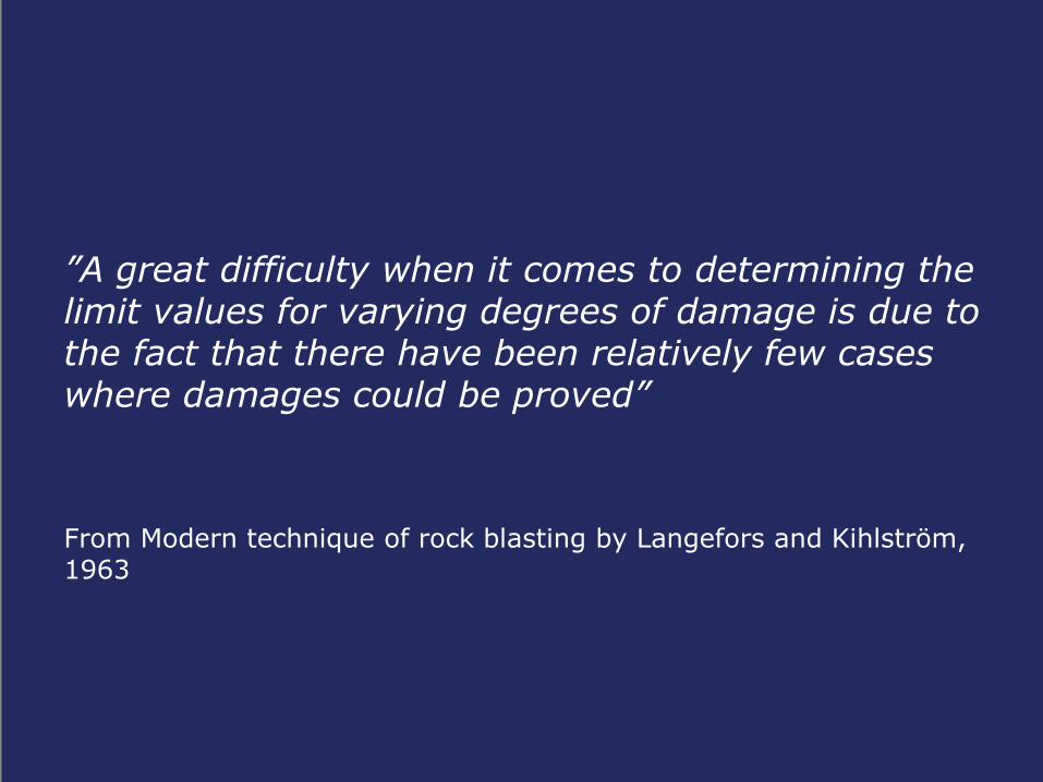
”A great difficulty when it comes to determining the limit values for varying degrees of damage is due to the fact that there have been relatively few cases where damages could be proved”
From Modern technique of rock blasting by Langefors and Kihlström, 1963

Common Blasting Projects in Urban Areas High Priced Ground
Foundation for building/construction/bridge projects
Removing roads/railroads subsurface
Removing cables/pipelines/sewer/drainage into tunnels
Free surface ground for housing/offices, build below (storage, sporting arenas, parking, shopping)
Cooling/heating plants
Conclusion: blasting is getting more complicated
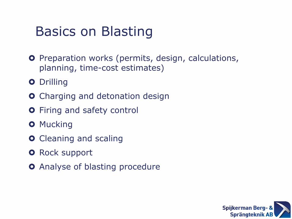
Basics on Blasting
Preparation works (permits, design, calculations, planning, time-cost estimates)
Drilling
Charging and detonation design
Firing and safety control
Mucking
Cleaning and scaling
Rock support
Analyse of blasting procedure

Most Important: Geology Bild från ”modern sprängteknik”

Considerations for Rock Excavation
Assessment of rock rippability based on
field mapping (Franklin et al (1971).

Bench Blasting
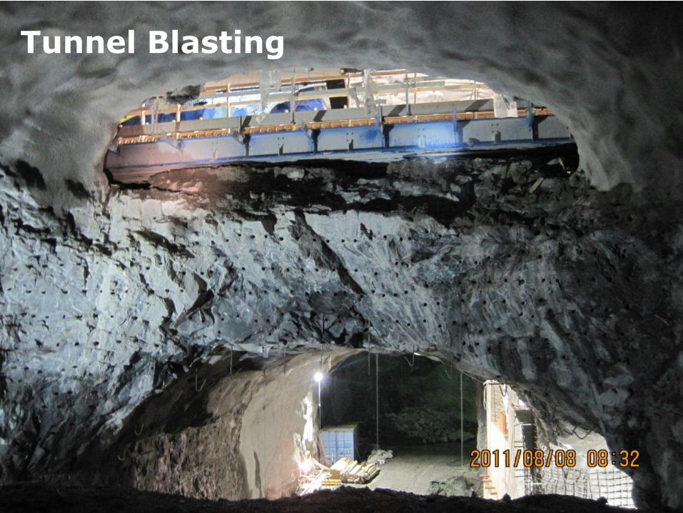
Tunnel Blasting

Risk Analysis Before Blasting
Risk Analyses Before Blasting

Risks in urban area blasting

Factors Influencing Blasting Effects

Differences in P-waves and S-waves
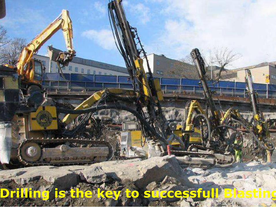
Drilling is the key to successfull Blasting

Drilling Design Pattern
Rock excavation on top of tunnel

Results…

Vibration Equipment
Automatically transfer data to NCVIB.com
All instrument with GSM modem
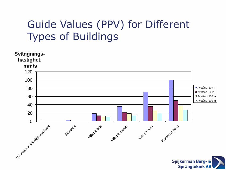
Guide Values (PPV) for Different Types of Buildings
0
20
40
60
80
100
120
Svängnings-hastighet,
mm/s
Avstånd, 10 m
Avstånd, 50 m
Avstånd, 100 m
Avstånd, 200 m

Type of tunnel PPV, mm/s PPD, mm
Metro tunnels in rock (traffic
operating)
60 – 92
(30)
-
Metro tunnels – concrete
(traffic operating)
100
(30)
-
Utility tunnels 70 or 100 -
District heating pipes - 3001) mm
1) Replaces rule that no blastings when temperature below -10 C
Utility tunnels – guide values

Electronic Detonators Unlimited Time Delays

FEM modelling vibrations

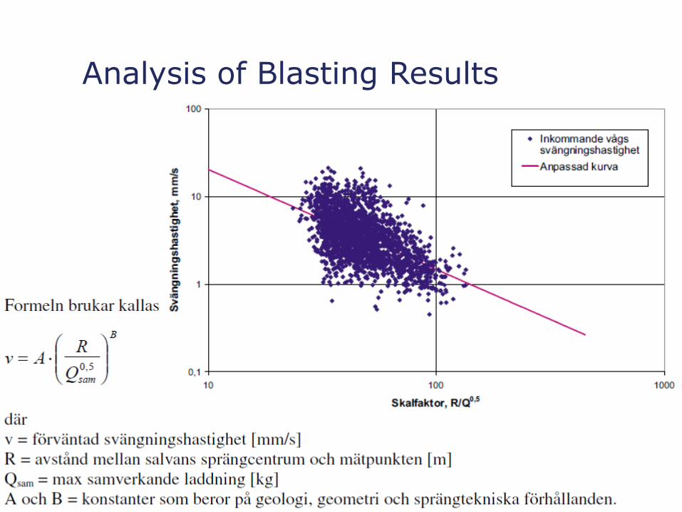
Analysis of Blasting Results
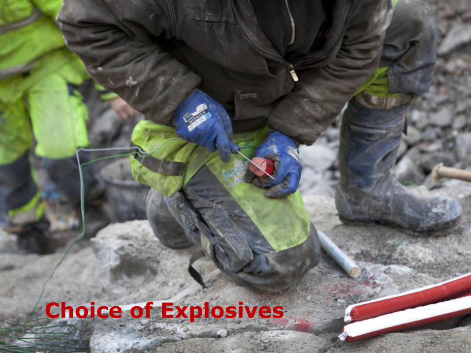
Choice of Explosives

• Detonation velocity • Strength • Detonation stability • Flash-over capacity • Density • Water sensitivity • Detonation sensitivity • Safety characteristics • Environmental characteristics
Conclusion: the contractor must have a range of Different products in order to perform a successful blast.
The Behaviour of an Explosive

Blasting Cord, But Splitting Along Crack

Damage zones of different explosives

Dynotex 17 mm

Alternative Mechanized Methods
Chipping /Hammering
Fracturing hydraulic (fracturing tools or chemicals)
Cutting the rock (Roadheader, diamond wire saw)
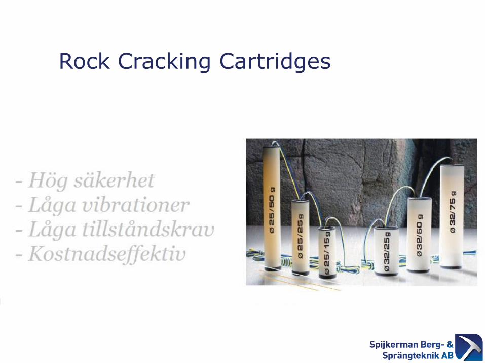
Rock Cracking Cartridges

Wire Cutting All Contours

Wire Cutting

FEM Analysis Effect of a Slot in the Contour
XY
Z
Model: SCHAKTVNOLL_: vnoll__1m/sStep: 61 TIME: .122E-1Nodal VELOC V3Max/Min on model set:Max = .519E-1Min = -.498E-1
0.909E-3.182E-2.273E-2.364E-2.455E-2.545E-2.636E-2.727E-2.818E-2.909E-2.1E-1
Här står Matteus kyrka
09 MAR 2010 15:18:52 fig.cgmFEMGV 7.1-02 : Grontmij AB
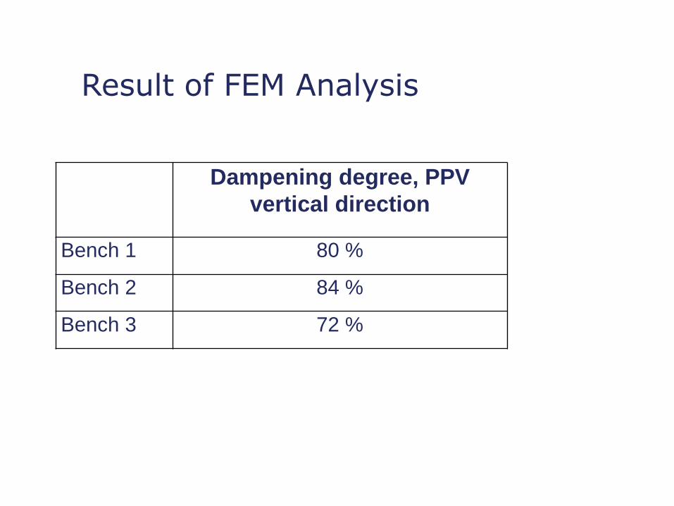
Result of FEM Analysis
Dampening degree, PPV
vertical direction
Bench 1 80 %
Bench 2 84 %
Bench 3 72 %

Monitoring Points

Average Damping Ratio
Monitoring Poing Damping ration –
bench 1, [%]
Damping ration –
bench 3, [%]
Behind the slot,
Vertical direction
72 71
Behind the slot,
Longitudinal
50 61
Behind the slot,
Transversal
42 33
Church, MS013-003,
Vertical
77 75
Church, MS013-005,
Vertical
69 37
Data provided by Nitro Consult

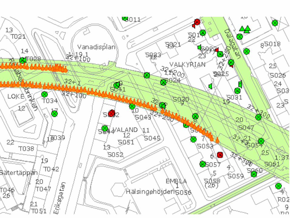
Example of Urban Blasting Project Stockholm City Link Railway project

6 km railway tunnel
2 tracks
3 stations
1,5 km fly over bridge
Double capacity & easy availability
=
+

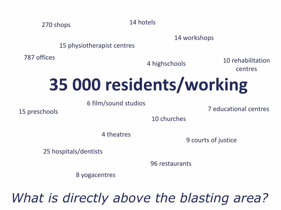
35 000 residents/working
15 physiotherapist centres
25 hospitals/dentists
10 rehabilitation centres
15 preschools
4 highschools
7 educational centres
9 courts of justice
10 churches
14 hotels
4 theatres
6 film/sound studios
8 yogacentres
787 offices
270 shops
96 restaurants
14 workshops
What is directly above the blasting area?

Risk Investigation Area
Approx. 2000 Buildings above the rock tunnels
13 crossings with utility tunnels – rock cover 0 to 10 meters
70 electrical substations
60 switching center for Telecommunications
4 crossings of metro tunnels & stations

Blasting for a New Metro Station

Potential Damage Risks
Relationship between natural frequency of wall and fre-quency of imposed vibration. Damages can be caused by:
• Elongation
• Shearing
• Bending
Existing static state of building unknown…
Foundation unknown or transfer mechanism between foundation and building unknown…
Vibration energy…
Solution: FEM modelling or conservative attitude

FEM Model of Gustaf Vasa Church

Results of Analysis
Part of the Church Safe value, PPV mm/s
Comments
Foundation and Columns
30 Theoretical limit for new cracks 36 mm/s (tensilse strength 200 kPa)
Columbariet 20
Arch vaults (Johannes, Matteus, Lukas)
20 Acceleration 4,8 g
Arch vault (Marcus) 15 Safety factor set at 5 for avoiding loosening of plaster
Altar Piece 10 Incoming vibration measured at floor level

Church Permitted PPV, mm/s
Alarm value, mm/s
Comments
S:t Matteus Church 22 13
Gustaf Vasa Church 18 13
S:t Clara Church 12 5 Distance >40 m
Adolf Fredrik Church 7 3 Foundation on sand/gravel.
Distance >130 m
Maria Magdalena Church 10 7 Foundation on sand/gravel.
Permitted Vibration Levels in Churches

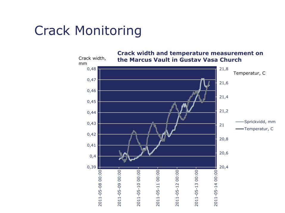
Crack Monitoring
20,4
20,6
20,8
21
21,2
21,4
21,6
21,8
0,39
0,4
0,41
0,42
0,43
0,44
0,45
0,46
0,47
0,48
2011-0
5-0
8 0
0:0
0
2011-0
5-0
9 0
0:0
0
2011-0
5-1
0 0
0:0
0
2011-0
5-1
1 0
0:0
0
2011-0
5-1
2 0
0:0
0
2011-0
5-1
3 0
0:0
0
2011-0
5-1
4 0
0:0
0
Sprickvidd, mm
Temperatur, C
Crack width and temperature measurement on the Marcus Vault in Gustav Vasa Church Crack width,
mm
Temperatur, C
Crack Monitoring

Damages - Natural Causes or Blasting?

• Blasting works are fully possible in urban areas
• Rock blasting opens new possibilities (creating space)
• An accurate planning and execution is a demand
• Modern techniques available
• But… very many prejudices
Conclusions
Very important questions:
What is a damage?
Cost of damage vs. Cost of project
Thx to Trafikverket, Nitro Consult, Skanska & Royex