Embed Size (px)
Citation preview

Caution: This document contains mixed page sizes (8.5 x 11 or 11 x 17), which may affect printing. Please adjust your printer settings
according to the size of each page you wish to print.

MCE Ensign Series 4500/6500
Printed in U.S.A. 927-0600 8-93

Safetv Precautions Before operating the generator set, read the Operator's Manualand become familiarwithitand your unit. Safe andeffl- cient operation can be achieved only if the unit is properly operated and maintained. Many accidents are caused byfail- ure to follow fundamental mles and precautions.
Thruugkout this manual you will notice symbolswhich alert you to potenliaHy dangerous conditions to the operator, service per- sonnel, or the equipment itself.
. l ' This symbd warns of immediate haz- ards which wiil result in severe personal fnjury or death,
EWARtMG, This symbol refers to a hazard or unsafe practice which can resuit in severe personal injury or death.
l%~cAu-tror\l Thls symbol refers to a hazard or unsafe practh? which can result in personal Injuv or prod- oct or property damage.
FUEL, ENGINE OIL, AND FUMES ARE FLAMMABLE AND TOXIC. Fire, explosion, and personal injury can result from im- proper practices.
Benzene and lead, found in some gasoline, have been identified by some state and federal agencies as causing cancer Or reproductive toxicity. When checking, draining or adding gasoline, take care not to ingest, breathe the fumchs, or contact gasoline.
Used engine oils have been identified by some state or federal agencies as causing cancgr or reproductive toxic- ity. When checkingor changing engine oil, take care not to ingest, breathe the fumes, or contact used oil.
Do not fil l fueltankswith the engine running. Do not smoke around the generator set area. Wipe up any oil or gas spills. Do not leave oily rags in engine compartment or on the generator set. Keep this and surrounding area clean.
InsprxAfuel system before each operation and periodically while running.
Equip the engine fuel supply with a positive fuel shutoff.
Always disconnect the battery ground (-) lead first and re- conmct it last. Make sure you connect the batlery cor- rectly. A direct short across the battery terminals can CPUSCI an explosion. Do not smoke while servicing batter- ies. Hydrogen gas given off during charging is very explo- sive.
Keep a fire extinguisher available in or near the engine cornpa-tment and in other areas throughout tke vessel. Use the correct ex?inguisher for the area. For most types of fires, an extinguisher rated AB6 by the NFPA is avail- able ancl suitable for use on all types of fires except alco- hol.
EXHAUST GASES ARE DEADLY e Provide adequate ventilation. Equipthe bilge with a power
exhauster.
Be sure propuhion and generator set engine exhaust zys- terns are free of leaks. Perform thorough, pcriodrc in:pec- tions of the exhaust system and repair leaks immedistsly. E:<haust gases are deadly.
Never sleep in the vessel with the generator set running unless the vessel is equipped with an operating carbon monoxide detector. ,
HOT COOLANT CAN CAUSE SEVERE PERSONAL INJURY
Hot coolant is under pressure. Do not loossn the coolant pressure cap while the engine is hot. Let the engina coal before opening the pressure cap.
MOVING PARTS CAN CAUSE SEVERE PERSONAL INJURY OR DEATH
Do not remove any belt guards or covers with the genm- tor set running.
Keep hands and loose clothing away from moving parts. Do not wear jewelry while servicing any part of the genera- tor set.
Never step on the gsnerator set (aswhen entering or leav- ing the engine compartment). It can stress and break unit components, possible resulting in dangerous operating conditions. . from leaking f u d , leaking exhaust fumes, etc.
Before performing any maintenance on the gerierator cet, disconnect its batteries to prevent accidental starting. do not disconnect or connect battery cables i f fuel vapors are present. Ventilate the generator set compartment or bilge thoroughly with the power exhauster.
ELECTRICAL SHOCK WILL CAUSE SEVERE PERSONAL INJURY OR BEATH
Do not make adjustments in the control panel or on engine with unit running. High voltages are present. Work that must be done while unit is running should be done only by qualified service personnel standing on dry surfaces to re- duce shock hazard.
.
DO NOT CONNECT THE GEldEFWTOR SET TO THE PUBLIC UTILllY OR TO ANY OTHER ELECTRICAL POWER SYSTEM. Etectrocuti n or damage to property can occur at a sita remote from the boat where line cor equipment repairs are being made if the s t is connected tothe power system. An approved bander switch mu3 be used if more than one power source iz to be made avail- able to service the boat.
Do not workon thisequiprnentwhen ~enfa:llyor physically fatigued, or after consuming any alcohol or drug that makes the operation of equipmmt unsafe. bit 8
Copy and post these suggestloris in potential hazard areas of the vessel.

Table of Contents
SECTION TITLE PAGE
1 .
2 .
3 .
4 .
5 .
6 .
7 .
8 .
9 .
10 .
SAFETY PRECAUTIONS ............................... Inside Front Cover
INTRODUCTION ................................................... 1-1 General ......................................................... 1-1 Installation Codes and Safety Recommendations ........................ 1-1
Generator Details ................................................. 2-1 Engine Details ................................................... 2-1
Location ........................................................ 3-1 Mounting ........................................................ 3-1
General ......................................................... 4-1 Requirements .................................................... 4-1 Coast Guard and NFPA Requirements ................................ 4-1
General ......................................................... 5-1 Heat Exchanger Cooling ............................................ 5-1
SPECIFICATIONS .................................................. 2-1
LOCATION AND MOUNTING ......................................... 3-1
VENTILATION ..................................................... 4-1
COOLING SYSTEM ................................................. 5-1
Sea Water Cooling ................................................ 5.3 Combined Cooling Systems ......................................... 5.3
EXHAUST SYSTEM ................................................ 6.1 General ......................................................... 6. 1 Below Load Waterline Installation .................................... 6-3 Above Load Waterline Installation .................................... 6-4
FUELSYSTEM .................................................... 7.1 General ......................................................... 7-1 Installation ...................................................... 7.1 Fuelianks ...................................................... 7.2 Fuel tines ........................................................ 7.3 SiphonProtection ................................................. 7-3 FuelSystemTest ................................................. 7-3
ELECTRICAL SYSTEM .............................................. 8-1 General ......................................................... 8-1 Load Connections .................................................. 8-1 Remote Starting Controls ........................................... 8-4 Batteries ........................................................ 8-4
Installation Checks ................................................ 9.1 Initial Starting and Checks .......................................... 9-1
FINAL INSTALLATION CHECKS ...................................... 9.1
DC WIRING DIAGRAM ............................................. 10-1
i


Section 1. Introduction
GENERAL Each marine generator set must be installed properly if it is to operate reliably, quietly, and most important - safely. Therefore, read this entire manual before starting the installation. The manual should be used only as a guide as each installation must be considered on an individual basis. For operation and maintenance proce- dures, refer to the MCE Operator‘s Manual 927-0124 which accompanies each unit
Proper installation is very important Requirements to consider should include:
Adequate cooling air a Adequate combustion air a Discharge of exhaust gases a Discharge of circulated air
Electrical connections and bonding Fuel connections Sea water connections
a Accessibility for operation and servicing a Level mounting surface a Adequate support under mounting points a Noise levels
INSTALLATION CODES AND SAFETY RECOMMENDATIONS
The insthation must follow recommendations of the American Boat and Yacht Council (ABYC) and the National Fire Protection Association (NFPA).
The installer should be familiar with and follow the appropriate guidance found in the following publications:
ABYC “Safety Standards for Small Craft”from: ABYC 15 East 26th St New York, NY 10010
NFPA302 “Fire Protection Standard for Motor Craif”from: NFPA 470 Atlantic Avenue Boston, MA 02210
USCG 33CFR183 from: U.S. Government Printing Office Washington, D.C. 20404
~AWARNING 1 INCORRECT SERVICE OR REPLACEMENT OF PARTS CAN RESULT IN SEVERE PERSONAL INJURY, DEATH, AND/OR EQUIPMENT DAMAGE. SERVICE PER- SONNEL MUST BE QUALIFIED TO PERFORM ELECTRICAL AND/OR MECHANI- CAL SERVICE.
1 =I

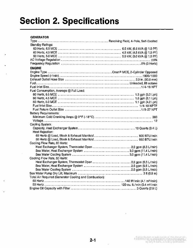
Section 2. Specifications
GENERATOR Type ................................................ Revolving Field, 4-Pole, Self-Excited Standby Ratings:
60 Hertz, 6.5 MCE ........................................... 6.5 kW, (6.5 kVA @ 1.0 PF) 60 Hertz, 4.5 MCE ........................................... 4.5 kW, (4.5 kVA @ 1.0 PF) 50 Hertz, 5.0 MCE ........................................... 5.0 kW, (5.0 kVA @ 1.0 PF)
AC Voltage Regulation ............................................................. +5% Frequency Regulation ...................................................... .5% (3 Hertz) ENGINE Engine Type ............................................ Onan@ MCE, 2-Cylinder Opposed Engine Speed (r/min) ......................................................... I800/1500 Exhaust Outlet Hose Size ............................................... .2.0 in. (50.8 mm) Fuel.. .............................................................. Unleaded, 88 octane Fuel Inlet Size.. ............................................................ .1/4-18 NPT Fuel Consumption, Average @ Full Load:
60 Hertz, 6.5 MCE .................................................... 1.3 gph (5.0 Lph) 60 Hertz, 4.5 MCE .................................................... 1.6 gph (6.1 Lph) 50 Hertz, 5.0 MCE .................................................... 1.1 gph (4.2 Lph) Fuel Inlet Size.. ......................................................... 1/4-18 NPTF Fuel Return Outlet Size ................................................... .1/8-27 NPT
Minimum Cold Cranking Amps @ 0°F (-18°C). ...................................... 360 Voltage ........................................................................... 12
Capacity, Heat Exchanger System.. .................................... .10 Quarts (9.4 L) Heat Rejection:
60 Hertz @ Load, Block & Exhaust Manifold.. ............................ 800 BTU/min 50 Hertz @ Load, Block & Exhaust Manifold.. ............................ 650 BTU/min
Heat Exchanger System, Thermostat Open ......................... .2.2 gpm (8.3 L/min) Sea Water, Heat Exchanger System .............................. .3.0 gpm (1 1.4 L/min) Sea Water Cooling System ...................................... -3.0 gpm (1 1.4 L/min)
Heat Exchanger System, Thermostat Open ......................... .2.2 gpm (8.3 L/min) Sea Water, Heat Exchanger System ............................... .2.5 gpm (9.5 L/min) Sea Water Cooling System ....................................... .2.5 gpm (9.5 L/min)
Sea Water Pump Dry Lift, Maximum ............................................ 3 ft (0.9 m) Total Air Required (Generator Cooling and Combustion):
60 Hertz.. .................................................... .146 ft3/min (4.1 m3/min) 50 Hertz .................................................... 120 cu. ft./min (3.4 m3/min
Engine Oil Capacity with Filter ............................................ .3 Quarts (2.8 L)
Battery Requirements:
Cooling System:
Cooling Flow Rate, 60 Hertz:
Cooling Flow Rate, 50 Hertz:
2-1

Section 3. Location and Mounting
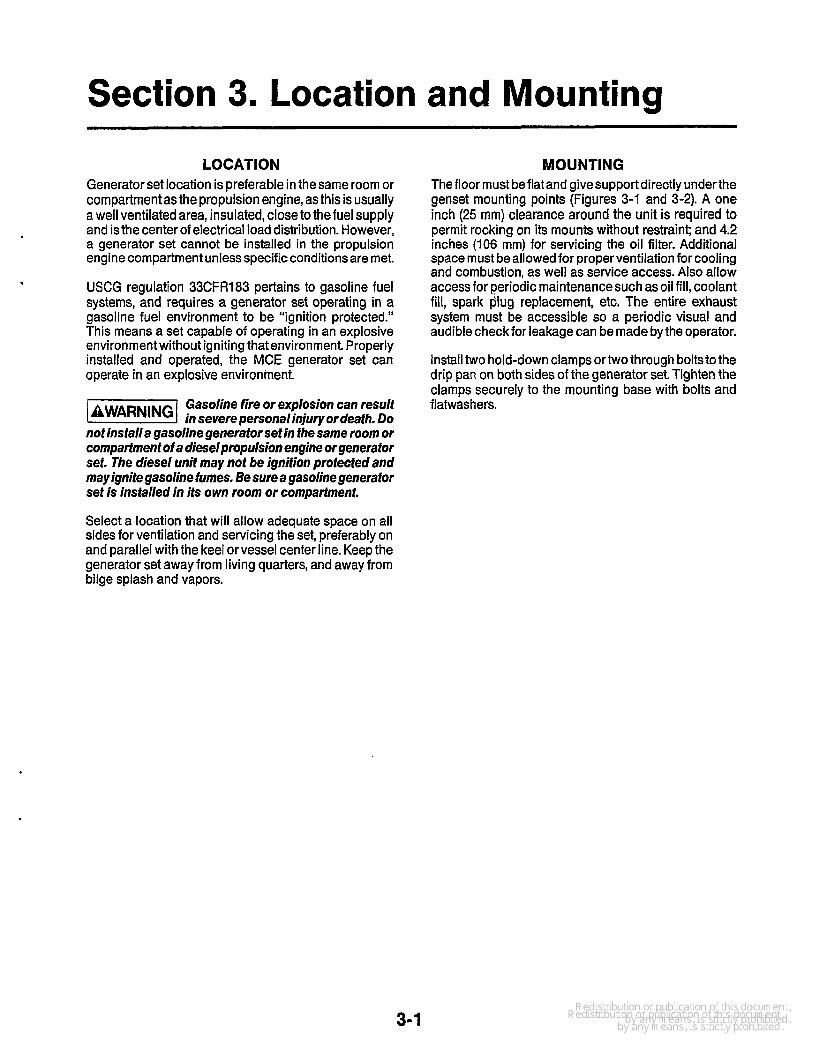
LO CAT1 ON Generator set location is preferable in the same room or compartment as the propulsion engine, as this is usually a well ventilated area, insulated, close to the fuel supply and isthe center of electrical load distribution. However, a generator set cannot be installed in the propulsion engine compartment unless specific conditions are met.
USCG regulation 33CFR183 pertains to gasoline fuel systems, and requires a generator set operating in a gasoline fuel environment to be “ignition protected.” This means a set capable of operating in an explosive environment without igniting that environment. Properly installed and operated, the MCE generator set can operate in an explosive environment.
Gasoline fire or explosion can result in severe personal iniury or death. Do
not installa gasoline generator set in the same room or compartment of a diesel propulsion engine or generator set. The diesel unit may not be ignifion protected and may ignite gasoline fumes. Be sure a gasoline generator set is insfalled in its own room or compartment.
MOUNT1 NG The floor must be flat and givesupport directly underthe genset mounting points (Figures 3-1 and 3-2). A one inch (25 mm) clearance around the unit is required to permit rocking on its mounts without restraint; and 4.2 inches (106 mm) for servicing the oil filter. Additional space must be allowed for proper ventilation for cooling and combustion, as well as service access. Also allow access for periodic maintenancesuch as oil fill, coolant fill, spark plug replacement, etc. The entire exhaust system must be accessible so a periodic visual and audible check for leakage can be made by the operator.
Install two hold-down clamps ortwo through boltsto the drip pan on both sides of the generator set. Tighten the clamps securely to the mounting base with bolts and flatwas hers.
Select a location that will allow adequate space on all sides for ventilation and servicing the set, preferably on and parallel with the keel or vessel center line. Keep the generator set away from living quarters, and away from bilge splash and vapors.
3-1
2 (i
I
3
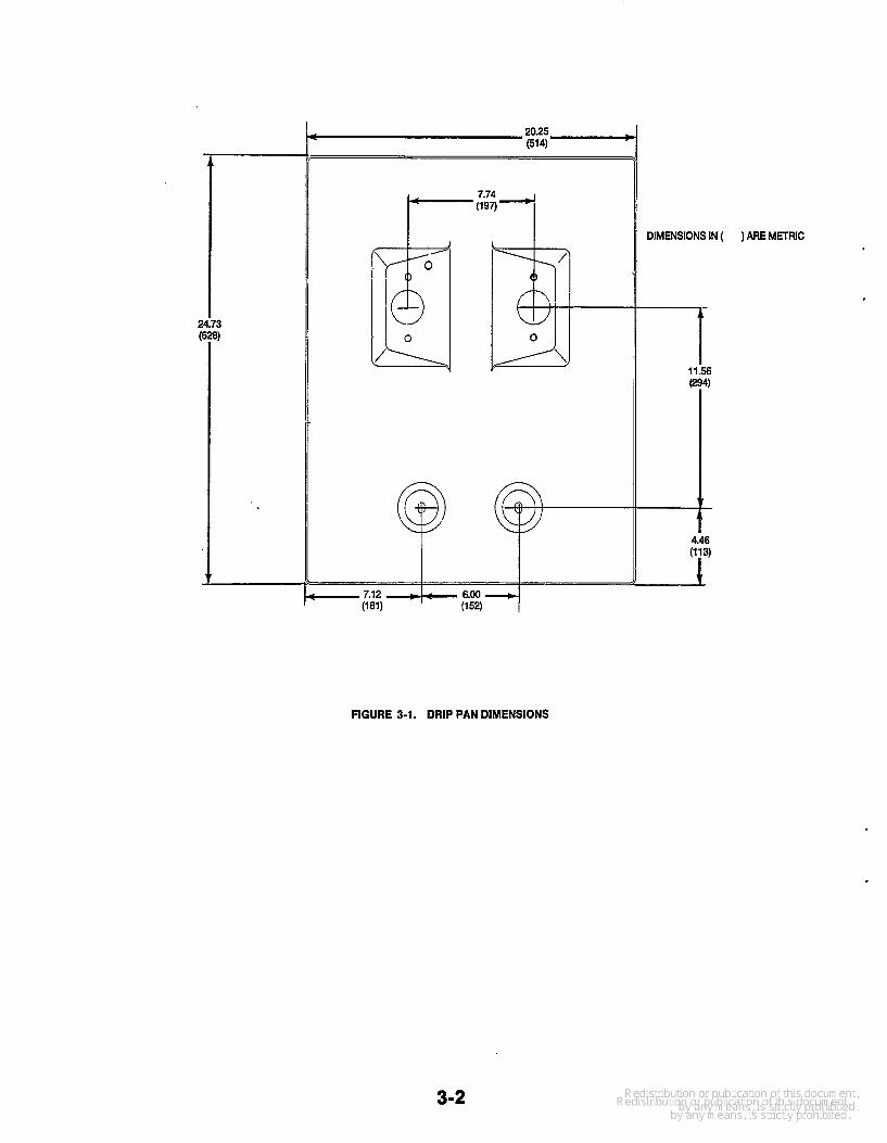
FIGURE 3-1. DRIP PAN DIMENSIONS
DIMENSIONS IN (
4.k
"i"
) ARE METRIC
3-2
(HEAT EXCI
SIDE VIEW
NOTES I
I .DIMENSIONS I N t l ARE MILLIMETERS
2.DRY WEIGHT! 335 LBS (152 Kgl COOLANT FILL
iANGER MODEL ONLY)
C CONNECTION . I2 (d HOLE(FARSIDE1
FRONl
I L FILL COOLANT FILL
(HEAT EXCHANGER MODEL ONLY1
1.19 4 I /WET EXH! 1 ’ 18.04(30.2) {
20.43 4 l518.9)
2.00 I D
HOSE 20.25 (50.8) (458.31
4.18 (106.2) O I L FILTER REMOVAL
(514.3)
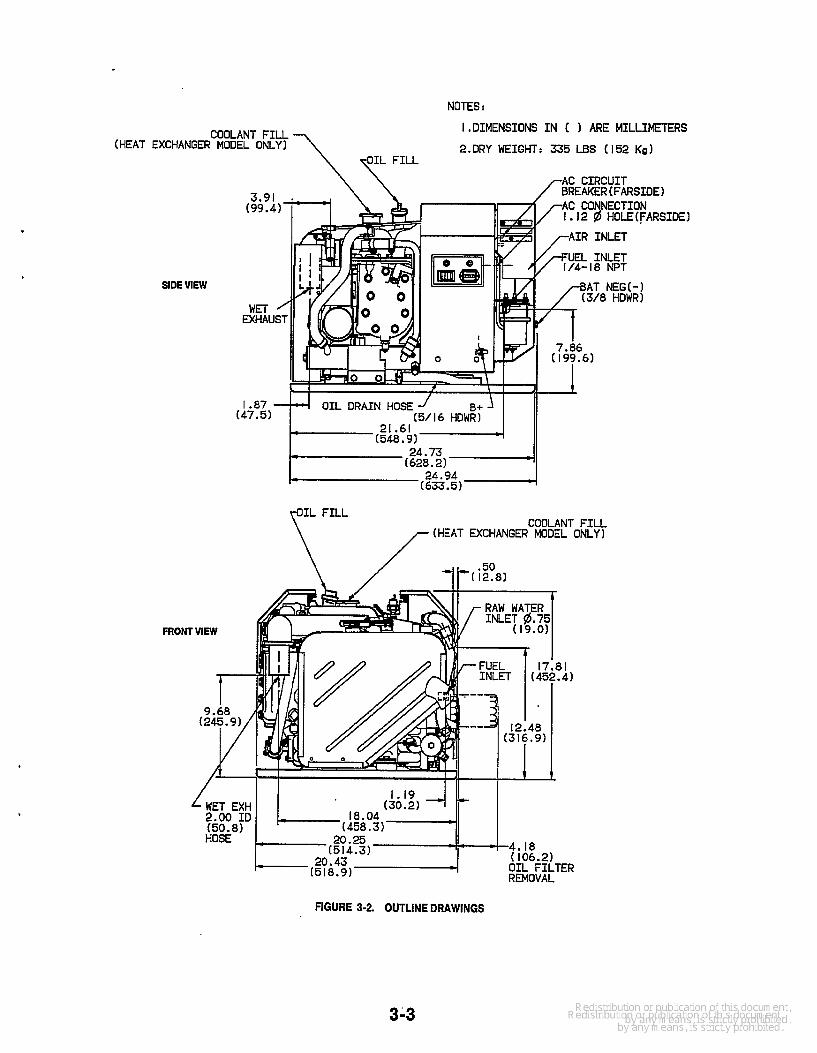
FIGURE 3-2. OUTLINE DRAWINGS
3-3


Section 4. Ventilation
GENERAL The installation of boat ventilation systems must meet all Coast Guard and NFPA requirements. Establishing the correct air flow quantity is particularly important with small compartments under 1000 cubic feet (28 m3), or installations in close quarters. Ventilation systems meet- ing Coast Guard requirements for gasoline engines in passenger vessels (Table 4-1) will normally suffice, however special consideration must be given to com- partment conditions during operation.
TABLE 4-1. PASSENGER VESSEL VENTILATION REQUIREMENTS
SIZE OF MINUTES REQUIRED COMPARTMENT TO EXCHANGE TOTAL
Cu. Ft. (m3) AIR VOLUME
Less than 500 (14) 2 500 to 1000 (14 to 28) 1000 to 1500 (28 to 42)
1500 and Up (42 and Up)
3 4 5
REQUIREMENTS Marine generator sets must have air ventilation for three very important reasons:
1. To remove flammableor other harmful gases. Coast Guard regulations require power blowers in the generator set and propulsion engine rooms be run at least four minutes priortostarting the engineand during operation. The operator must also inspect the engine room for the presence of fuel vapors prior to starting, especially when gasoline fueled equipment is used (see text under Coast Guard and NFPA Requirements).
2. To provide engine combustion air and generator cooling air. Coast Guard regulations require power exhausters in all installations, and one blower in each exhaust duct. Exhausters must have an air capacity 1-1 /2 to 2 times the minimum generator set total air requirements. The MCE generator set requiresa total operation minimum of 146 cubic feet per minute (4.2 m3/min).
3. To control compartment temperature during genset operation. This will avoid overheating which can result in shutdown from vapor lock, engine and related control component damage, and power loss. As a general rule, the operating environment for a gasoline genset should not be higher than 14OOF (60OC) maximum. Lower temperatures are recommended. Often an operating power blower may be required to maintain temperature when the genset is operating, especially when the boat is not moving.
The compartment must have air inlets and outlets to provide this air. Inlet ducts should have cowls or equi- valent fittings of twice the area of the duct, larger if the opening is screened. Do not use recessed or flushed inlets, or louvered transom outlets.
If the gasoline fuel tank is in a separate compartment, it also must be ventilated.
COAST GUARD AND NFPA REQUIREMENTS Both organizations require at least two inlet ducts and two outlet ducts extending to the bilge for gasoline generator set installations in a closed Compartment. When not in a closed compartment, at least one duct should be installed in the fore section of the boat and another aft. The NFPA recommends a vent size of at least two square inches per foot (42.3 cm2/m) of boat beam for total inlet area and total outet area.
Boats classified as pleasure vessels by the Coast Guard must have sufficient ventilation to eliminate accumula- tion of flammable gases. Boats under 65 feet (20 m) long classified as passenger vessels require ventilation be sufficient to change the compartment air within a given time interval (Table 4-1).
For passenger vessels, the Coast Guard recommends a mechanical exhausting system to meetthe requirement in Table 4-1. The exhaust blower motors should be outside the compartment.
If a gasoline fuel tank is in a separate compartment, it must be ventilated to the same requirements as the engine compartment.
4-1


Section 5. Cooling System
GENERAL Throughout this manual, flotation water drawn into the boat for engine cooling iscalled sea water. Water recircu- lated through the engine closed system is called captive water. Thus, confusion is avoided with other generic terms describing water use.
The two types of marine cooling systems covered in this manual are heat exchanger and sea wafer cooling. An explanation of each system, and the advantages and disadvantages of each are covered in separate chapter headings. The heat exchanger system is ordered most often and is standard on the MCE generator set Sea water cooling is an available option.
System Plumbing To adequately cool the generator set under all conditions, the plumbing system must be properly planned and installed. Excess lengths of plumbing increases flow resistance and results in reduced cooling. An air leak in the sea water intake will reduce cooling, cause corrosion, and can even destroy the neoprene impeller in the sea water pump. The neoprene impeller must never be run dry, and should be primed before initial start
The water line should have a minimum inside diameter of 0.75 inch (1 9 mm). For runs over 20 feet (5.2 m), increase the line one pipe size for each additional 10 feet (2.6 m) of length. Water lines can be either copper tubing or flexible hose. Be sure a length of flexible hose is used at the generator set connection to allow set movement and for noise abatement
Unless the sea water is very clean, Onan recommends a water strainer or filter to protect the sea water cooling system. See Figure 5-1.
Onan has a hull strainer (furnished with some muffler kits) that can be used with a flush through-hull fitting. The strainer (Figure !SI), installed with theslots parallel to the keel, helps prevent pressure or vacuum when the boat is underway. Always use a flush-type inlet with a hydrody- namic marine muffler.
The flush-fype through-hull wafer inlef must have an opening at least as
lame as fhe wafer inlef line.
TO GENERATOR
SET
RECOMMENDED WATER STRAINER
OR FILTER
FLUSH THRU- HULL FllllNG
STF CROSS-SECTION VlMl
HULL. --WNER
CS-1312-1
FIGURE 5-1. SEA WATER INLET
Stagger the generator set water inlet so it is not directly in line with other inlets. Not doing so can reduce the amount of sea water available to the generator set when under- way and cause overheating. Never use scoop type water inlet fittings with a hydrodynamic muffler.
-1 Do not use scoop fype wafer inlet fit- tings with a hydrodynamic muifler.
Forward facing scoops can develop suiiicienf rampres- sure to force wafer past the generator sefs sea wafer pump. This can floodfhe exhausfsystemandfhe engine cylinders. This happens when the generator set is not running and the boat is underway. Rear iacing scoops develop vacuum which can impede d i n g wafer flow.
HEAT EXCHANGER COOLING This cooling system, standard on the genset, keeps sea water and the resulting sediment deposits (salt, silt, etc.), from the engine cooling jacket It also provides more uniform cooling and temperature control in the engine. Sea water and captive water are kept separated, and the engine water jacket stays clean for optimum heat transfer.
5-1

Figure 5-2 shows the flow direction of sea water and captive water. The sea water pump constantly renews the cool water bath in the heat exchanger and exhaust system. The captive water is circulated by a pump through the engine block, heat exchanger, and the exhaust manifold. The captive water temperature and flow rate are controlled by thermostats.
Each genset has a recoverytank kit to be installed in the captive cooling system. The tank (similar to automotive application) is connected to the overflow fitting below the pressure cap. It keeps the captive system filled with coolant which helps prevent corrosion and sediment. The tankshould be locatedforeasychecking of coolant level, and for serviceability. lnstallation instructions are furnished with the kit.
BELT-DRIVEN SEA WATER PUMP HEAT EXCHANGER
r- I
FROM SEA WATER INLET
The captive cooling system should always use a 50-50 mixture of ethylene glycol and distilled water to help prevent corrosion. See the lnstallation Checkout sec- tion for filling instructions.
If a heat exchanger other than the Onan standard is installed, several precautions are required as follows:
The heat exchanger must properly cool thegenera- tor set under all load conditions.The Onan system is designed to cool the set at full load with sea water inlet temperatures up to 1 OOOF (38OC). Extra margin (10%) must be allowed for varying conditions of pumps, coolant and scale build up.
Minimum captive water and sea water flow required by the generator set must be met. The heat exchanger will also have minimum and maximum flow requirements which must be met for cooling at its capacity. The generator set requirements are listed in the Specificafion section.
r* I I t I I I
I
.-*----
t MANIFOLD
(MIXER)
EXHAUST AND SEA WATER OUTLET
TO MUFFLER
by Separate Pump
--P Captive Cooling Water Circulated by
cs1369
....
FIGURE 5-2. COOLANT FLOW, HEAT EXCHANGER COOLING SYSTEM
5-2

SEA WATER COOLING The sea water cooling system is shown in Figure 5-3. This system uses the belt-driven sea water pump to direct water through the engine cooling system and out the exhaust system. The electric circulating pump is not used on this system. The engine blocks have a drilled coolant bypass hole to allow some coolantflow regard- less of thermostat opening. This allows for exhaust cool- ing and protection of the pump. The sea water and exhaust is disposed of similarly as described in Heat Exchanger Cooling with a hydrodynamic muffler (above or below water line installation).
The sea water comes into direct contact with the engine cooling jacket, and this system should be avoided for use in salt or contaminated water. Such water can cause engine block corrosion and/or plugging; there- fore, heat exchanger systems are recommended.
.
COMBINED COOLING SYSTEMS Onan does not recommend combining the generator set cooling system with the propulsion engine cooling sys- tem. This involves a great amount of experience and knowledge for the installer, as well as complete know- ledge of characteristics of both the generator set and propulsion engines.
Propulsion engines use scoop-type water inlet fittings which must not be
used for a generator set with a hydrodynamic muffler. When not operating, ram pressure can force waferpast the generator set’s sea water pump and flood the exhaust system. From here it can flow back, flooding the engine cylinders and possibly the engine com- partment.
BELT-DRIVEN SEA WATER PUMP EXHAUST
MANIFOU)
I ,- I EXHAUSTMANIFOLD / I \ FROM SEA I (MIXER) / I \ + WATER INLET
I
r e I
EXHAUST AND SEA WATER OUTLET TO MUFFLER
I I + I
I
I
FIGURE 5-3. COOLANT FLOW. SEA WATER COOLING
5-3


Section 6. Exhaust System
GENERAL The installation of two water-cooled exhaust systems are covered in this section. They are below-load waterline and above-load waterline, and are covered under separ- ate headings. All exhaust systems for water-cooled marine installations must meet each of the following requirements. Failure to meet these requirements could result in severe property damage, personal injury or death. b
The entire exhaust system must be accessible so a periodic visual and audible check for leakage can be made by the operator.
0 The exhaust system must be water cooled, and the water injected as near to the generator set as possible.
0 All exhaust system sections preceding the point of water injection must be water jacketed or effectively insulated or shielded.
0 The exhaust line must be installed to prevent back flow of water to the engine under any conditions; and the exhaust outlet must be above the load waterline. Water backflow into the engine will damage it
The generator set exhaust system must not be com- bined with the exhaust system of another engine.
0 A flexible section of marine exhaust hose must be used near the engine to allow for engine movement and vibration during operation. All exhaust system hoses must be CERTIFIED for marine use.
0 The exhaust system must be of sufficient size to pre- vent excessive back pressure. See Back Pressure data in this section.
Install exhaust through hull fitting aft of sink, shower or other cabin drains to prevent backflow of exhaust gases into the vessel.
Material Use material recommended by ABYC in “Safety Standard for Small Crafi, ”Section P1. The exhaust line must be at least as large as the engine exhaust manifold outlet See following section on Back Pressure.
Exhaust gas contains carbon monox- ide, an odorless, colorless, highly
poisonous gas that presents the hazard of severe per- sonal injuw or death. Place special emphasis on the following:
0 Be sure the flexible exhaust hose is designed and certified for marine exhaust line use.
Use two clamps at each end of all flexible exhaust hose connections.
Do not make shatp bends in the exhaust hose.
0 Position exhaust outlet to prevent backflow of
Use flexible hose designed and CERTIFIED for marine exhaust line use. The muffler must be at the lowest point of the entire exhaust system. The muffler top should be at least 12 inches (305 mm) below the exhaust manifold outlet If it is higher, backflow of water toward the manifold is more likely.
Make sure the hose drains toward the muffler at a grade of 1 /2 inch per lineal foot (42 mm/m). An uphill section between the exhaust manifold and muffler can cause backflow of water and is not permissible - NO EXCEPTIONS.
exhaust gases info the vessel.
Be sure that the vertical rise of the exhaust hose mea- sured fromthe bottom of the muffler to its peak is not more than 48 inches (1.2 m) as shown in Figure 6-1.
The exhaust tubing (on both above and below load water- line installations) must be pitched downward to the through-hull outletfitting ata minimum downgrade of 112 inch per lineal foot (42 mm/m). There must also be a 12-inch (305 mm) minimum drop from this peak to the through-hull outlet fitting as shown in Figures 6-1 and 6-2.
Allow space between the marine muffler and its mounting surface by use of spacers under the mounting flanges. This allows air circulation under the muffler and discour- ages condensation build-up.
6-1
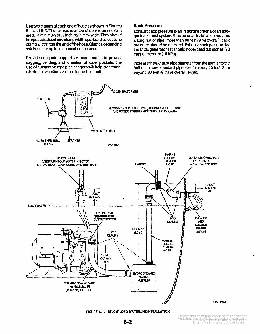
Usetwo clamps at each end of hoseasshown in Figures 6-1 and 6-2. The clamps must be Of corrosion resistant metal, a minimum Of% inch (12.7 mm) wide. They should be spaced at k is t one clamp width apart, and at least one clamp widthfromtheend ofthe hose. Clamps depending solely on spring tension must not be used.
Provide adequate support for hose lengths to prevent sagging, bending, and fOrmation Of water Pockets- The use ofautomotive@Pe Pipe hangers Will help stop tms- mission of vibration or noise to the boat hull.
Back Pressure Exhaust back pressure is an important criteria of an a&- quate exhaust system. If the exhaust installation requires a long run of pipe (more than 30 feet [9 m] overall), back pressure should be checked. Exhaust back pressure for the MCE generator set should not exceed 3.0 inches (76 rnm) of mercury (10 kPa).
Increase theexhaust pipe diameter from the mufflertothe hull outlet one standard pipe size for every 10 feet (3 m) beyond 30 feet (9 m) of overall length.
"\ TO GENERATOR SET
SEA c
RECOMMENDED FLUSH-TYPE, THROUGH-HULL FliTlNG AND WATER STRAlNER (NOTSUPPUED BY ONAN)
.
FLUSH THRU-HULL Sk/VNER CS-1312-1 FllTING
FIGURE 6-1. BELOW LOAD WATERLINE INSTAWTlON
6-2
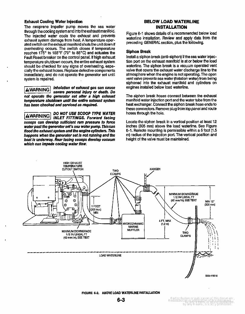
Exhaust Cooling Water Injection The neoprene impeller pump moves the sea water through the cooling system and into the exhaust manifold. The injected water cools the exhaust and prevents exhaust system damage from heat A temperature oper- ated switch on theexhaust manifold shu tsthe unit down if overheating occurs. The switch closes if temperature reaches 175' to 185°F (79' to 85'C) and actuates the Fault Reset breaker on the control panel. If high exhaust temperature shutdown occurs, the entire exhaust system should be checked for any signs of overheating, espe- cially the exhaust hoses. Replace defective components immediately, and do not operate the generator set until
Inhalation of exhaust gas can cause jawnR"Gl severe personal injury or death. Do not operate the generator set after a high exhaust temperature shufdown until the entire exhaust system has been checked and serviced as mquimd.
. system is repaired.
DO NOT USE SCOOP TYPE WATER -1 INLET FITTINGS. Forward facing scoops can develop suificient ram pressure to torce wafer past the generator set's sea waferpump. Thiscan flood the exhaust system and the engine cylinders. This happens when the generafor set is not running and the boat is underway. Rear facing scoops develop vacuum which can impede cooling water flow.
BELOW LOAD WATERLINE INSTALLATION
Figure 6-1 shows details of a recommended below load waterline installation. Review and apply data from the preceding G€N€ML section, plus the following.
Siphon Break Install a siphon break (anti-siphon) if the sea water injec- tion port on the exhaust manifold is at or below the load waterline. The siphon break is a vacuum operated vent valve that opens the exhaust water discharge line to the atmosphere when the engine is not operating. The open vent valve prevents sea water (flotation water) from being siphoned into the exhaust manifold and cylinders on engines installed below load waterline.
The siphon break hoses connect between the exhaust manifold water injection port and the water tube from the heat exchanger. Connect the siphon break hose ends to these connectors. Remove plug from top panel and route hoses through the hole.
Locate the siphon break in a vertical position at least 12 inches (305 mm) above the load waterline. See Figure 6-1. Remote mounting is permissible within a 5 foot (1.5 m) radius of the injection port The vertical position and height of the valve must be maintained.
HIGH EXHAUST TEMPERATURE
CUTOUT,SWITCH TWO HANGER
MINIMUM DOWNGRADE 112 INlLlNEAL FT
------------------------------------------------------- LOAD WATERLINE
FIGURE 6-2. ABOVE LOAD WATERLINE INSTALIATION
6-3

The siphon break must be mounted vertically with the threaded end pointed down. Use pipe strap material to secure the assembly to the frame or bulkhead. Be sure the slotted opening in the siphon break valve is open to atmospheric pressure. The valve will not function if the slot is closed in any way.
1-1 Failure to use a siphon break when the exhaust manifold injection port is
at or below the load waterline will result in sea water damage to the engineandpossible flooding of tbe boat.
ABOVE LOAD WATERLINE INSTALLATION
Figure 6-2 shows detailsof a recommended above load waterline installation. A siphon break valve is not required with this installation. Review and apply data from the preceding GENERALsection. Be sure the min- imum drop and downward pitch of exhaust runs are applied, and that all hose end connections have two clamps as shown.
6-4
.
Section 7. Fuel System
GENERAL
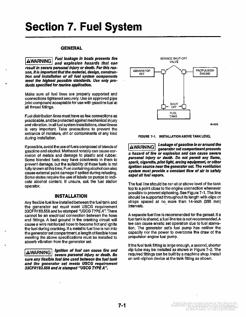
Fuel leakage in boats presents fire -1 and explosion hazards that can result in severe personal injury or death. For this rea- son, it is important that the material, design, consfruc- tion and installation of all fuel system components meet the highest possible standards. Use only pro- ducts specified for marine application.
Make sure all fuel lines are properly supported and connections tightened securely. Use an approved pipe joint compound acceptable for use with gasoline fuel at all thread fittings.
Fuel distribution lines must have as few connections as practicable, and be protected against mechanical injury and vibration. In all fuel system installations, cleanliness is very important. Take precautions to prevent the entrance of moisture, dirt or contaminants of any kind during installation.
If possible, avoid the use of fuels composed of blends of gasoline and alcohol. Methanol notably can cause cor- rosion of metals and damage to plastic and rubber. Some blended fuels may have cosolvents in them to prevent damage, but the suitability of these fuels is not fully known at thistime. Fuel containing alcohol can also cause external paint damage if spilled during refueling. Some states require the use of labels on pumps to indi- cate alcohol content If unsure, ask the fuel station operator.
INSTALLATION Any flexible fuel line installed between the fuel tank and the generator set must meet USCG requirement 33CFR183.558 and be stamped “USCG TYPEA”. There cannot be an electrical connection between the hose end fittings. A bad ground in the cranking circuit will cause a wire reinforced hose to become hot and ignite the fuel during cranking. If a metallic fuel line is run into the generator set compartment, a length of flexible hose meeting the above specifications must be installed to absorb vibration from the generator set.
Ignition of fuel can cause fire and severe personal injury or death. Be
sure any flexible fuel line used between the fuel tank and the generator set meets USCG requirement 33CFR183.558 and is stamped “USCG TYPE A”.
SERVICE SHUT-OFF VALVE
PROPULSION ENGINE
GENERATOR
FUEL TANK
FIGURE 7-1.
I I
M-1679
INSTALLATION ABOVE TANK LEVEL
Leakage of gasoline in or around the generator set compartment presents
a hazard of fire or explosion and can cause severe personal injury or death. Do not permit any flame, spark, cigarette, pilot light, arcing equipment, or other ignition source near fhe generator set. The ventilation system must provide a constant flow of air to safely expel all fuel vapors.
The fuel line should be run at or above level of the tank top to a point close to the engine connection whenever possible to prevent siphoning. See Figure 7-1.The line should be supported throughout its length with clips or straps spaced at no more than 14-inch (355 mm) intervals.
A separate fuel line is recommended for the genset. If a fuel tank is shared, afuel linetee isnotrecommended-A tee can cause erratic set operation due to fuel starva- tion. The generator set’s fuel pump has neither the capacity nor the power to overcome the draw of the propulsion engine fuel pump.
If the fuel tank fitting is large enough, a second, shorter dip tube may be installed as shown in Figure 7-2. The required fittings can be built by a machine shop. Install an anti-siphon device at the tank fitting as shown.

FUEL LINE TO PROPULSION ANTI-SIPHON FUEL UNE TO
ENGINE DEVICE GENERATOR SET
HEX HEAD CAP FTTTING
FIGURE 7-2. TWO FUEL LINES IN TANK FllllNG
1-1679.2
If the tank does not have an unused outlet, a new outlet can be installed. The metal tank must be removed to braze or weld a new outlet fitting. This procedure
. requires the service of a welder familiar with the essen- tial safety measures.
1-1 Ignition of fuel vapors can cause severe personal injury or death.
Welding a fuel tank, empty or not, is extremely danger- ous! Vapors can ignite causing an explosion and fire.
Another consideration is the generator set fuel pump lift capacity. The vertical height must not exceed 4 feet (1.2 m), minus the requirement of an anti-siphon valve when used, or the generator set operation can be adversely affected.
FUEL TANKS Avalve must be installed directly at the tank connection to shut off fuel flow. This valve may be electrically or manually operated. If electrical1,y operated, it must be energized only during engine operation, and have a manual override to comply with USCG regulations. This electric valve can be purchased from Onan and is listed in the parts manual.
The manual valve must have an arrangement for operat- ing it outside the compartment in which the tank is located, preferable from above deck.
A USCG approved service shutoff valve must be installed at the engine end of the fuel line under condi- tions listed below. This valve stops fuel flow when the genset is serviced.
0 When fueltanksare located in a compartment other
When the engine and fuel tanks are separated more than the engine.
than 12 feet (3.7 m).
If the propulsion engines and generator set usedifferent fuels, a separate fuel tank will be required. Use only an approved fuel tank designed for marine application. Be sure thatthe Compartment is well ventilated (see Ventila- tion System section). Fuel consumption data in the Specificafionssection is useful for determining the tank size.
When installing a separate tank, locate it as close as possible to the generator set Compartment. Be sure it is accessible and can be removed for inspection.
Fuel starvation can cause marginal operation of the generator set. Fiber-
glass fuel tanks can present a problem if the fuel pick- up tube is too.close to the tank bottom. Fiberglass fibers can seftle and form a mat wifh time. Make a diagonal cut on the bottom of the pick-up tube and install 35 to Pinches (73 to 51 mm) from the fankbottom.
Mount the fuel tank and secure into position. The NFPA recommends that flat bottom tanks be installed on slat- ted wooden platforms to help prevent moisture conden- sation. Cylindrical tanks should be set in chocks or cradles and securely fastened.
Small fuel tanks can be suspended from deck beams. Support and brace the tank to prevent any movement. Line up braces with the tank internal baffle plates. Insu- late all wood or metal surfaces from the tank surface with a non-abrasiveand nonabsorbent material. Heavy rubber-impregnated cotton fabric or oil and acid- resistant plastics work well.
Ignition of fuel when filling the tank l&lZ@l can result in seuere personal injury or death. All metallic fuel tanks MUST be electrically bonded to the boat common ground. Also bond the filler neck or opening to the tank if a hose is used between them. This helps prevent static spark when filling that can ignite the fuel.
Position the tank fill and vent pipes so fuel or vapor cannot escape into the bilge. Run the vent and fill pipes from separate openings in the tank. If the fill pipe has a flexible section of fuel hose, install aseparate grounding wire between the deck fuel plate and tank. Install the vent opening as far from any other hull opening as possible and with a gooseneck so water cannot enter. Install a flame arrester on the vent opening.
7-2

FUEL LINES The proper installation of fuel lines is very important Give special attention to the following requirements.
0 All fuel line materials must meetthe requirementsof both the USCG and the ABYC.
0 Solid fuel lines must be seamless annealed, double- flared, and approved for marine installations.
0 Run fuel lines at the top level of tank to a point as close to the engine as possible to reduce danger of fuel siphoning should the line break.
areas. This reduces chance of vapor lock.
I
. 0 Keep fuel lines away from hot engine or exhaust
0 Any locked-in torsional stresses must be avoided in the fuel line.
0 Install a flexiblefuel line meeting USCG requirement 33CFR183.558, and stamped “USCG TYPE A” between the solid fuel line and engine to absorb vibration. The line length must be sufficient to pre- vent binding or stretching due to generator set movement.
, FUEL LINE I TO BOAT
I COMMON BONDING METALLIC FUEL CONDUCTOR
LINE FROM TANK ES-1891
FIGURE 7-3. FUEL LINE BONDING
Install fuel lines so they are accessible and pro- tected from damage.
Use non-ferrous metal straps without sharp edges to secure the fuel lines every 14 inches (355 mm).
Electrically bond a metallic fuel line to the vessel with a suitable bonding strap. The drip pan must also be bonded to thissame conductor asshown in Figure 7-3.
SIPHON PROTECTION A carburetor float valve cannot be trusted to stop fuel flow if there is gravity feed from the fuel tank. When the tank is installed above the engine level an anti-siphon device is needed to prevent the fuel from emptying into the carburetor if the float valve doesn’t close. It also prevents siphoning if the line breaks at a point below the fuel level.
Mandatory siphon protection must be provided by installing a U.S. Coast Guard approved anti-siphon device. See Figure 7-4. This device can be installed at the tank withdrawal fitting, or at a location where the line from the fuel tank will no longer remain above the fuel tank top level. The device can be either a mechanical check valve (1 f0.5 psi [6.9 53.5 kPa]), or an electric valve with mechanical override. The electricvalve must be connected so it operates only when the engine ignition is on.
ANTISYPHON VALVE OR ELECTRICALLY OPERATED FUEL STOP VALVE
M-1679
FIGURE 7-4. SIPHON PROTECTION
FUEL SYSTEM TEST After installation, test thefuel system fortightness by pumping air into the tank to a pressure Of 4 to 5 psi (28 to 35 kPa). Pressure must remain steady. If not, the leak must be found before putting the system into service.
7-3

.
Section 8. Electrical System
GENERAL All wiring &meet Coast Guard, NFPA, and all other applicable codes. Have all wiring installed by a qualified electrician. Onan wiring diagrams do not include com- ponents added by customers.
Faulty electrical equipment can cause shock and severe personal
injury or deafh. Use only approved power supply
the power cord. lncorrect or no ground may cause the vessel to be electrically "hot".
I assemblies, and never remove the grounding pin from
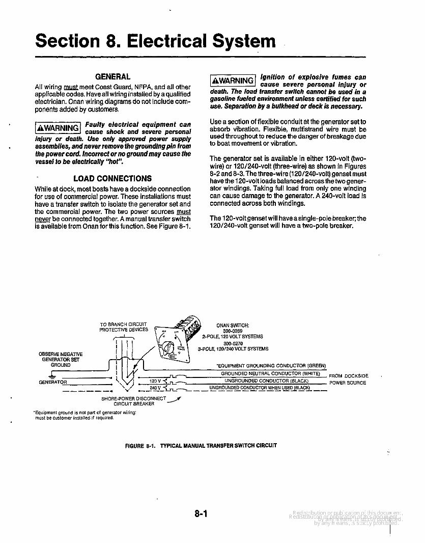
LOAD CONNECTIONS While at dock, most boats have a dockside connection for use of commercial power. These installations must have a transfer switch to isolate the generator set and the commercial power. The two power sources never be connected together. A manual transfer switch is available from Onan for this function. See Figure 8-1.
Ignifion of explosive fumes can IiEFi%I cause severe personal injury or death. The load fransfer switch cannot be used in a gasoline fueled environment unless certified for such use. Separation by a bulkhead or deck is necessary.
Use a section of flexible conduit at the generator set to absorb vibration. Flexible, multistrand wire must be used throughout to reduce the danger of breakage due to boat movement or vibration.
The generator set is available in either 120-volt (two- wire) or 120/240-volt (three-wire) as shown in Figures 8-2 and 8-3. The three-wire (1 20/240-volt) genset must have the 120-volt loads balanced across thetwo gener- ator windings. Taking full load from only one winding can cause damage to the generator. A 240-volt load is connected across both windings.
The 120-volt genset will haveasingle-pole breaker; the 120/240-volt genset will have a two-pole breaker.
ONAN SWITCH TO BRANCH CIRCUIT PROTECTIVE DEVICES 300-0269
2-POLE, 120 VOLT SYSTEMS 300-0270
3-POLE, 1201240 VOLT SYSTEMS OBSERVE NEGATIVE
GENERATOR SET GROUND 'EQUIPMENT GROUNDING CONDUCTOR '(GREEN)
L GROUNDED NEUTRAL CONDUCTOR (WHITE) UNGROUNDED CONDUCTOR (BLACK)
UNGROUNDED CONDUCTOR WHEN USED (BUCK)
- GENEGATOR
--------------- SHORE-POWER DISCONNECT /
CIRCUIT BREAKER
FROM DOCKSIDE POWER SOURCE
'Equipment ground is not part of generator wiring: must be customer installed if required.
FIGURE 8-1. TYPICAL MANUAL TRANSFER SWITCH CIRCUIT c
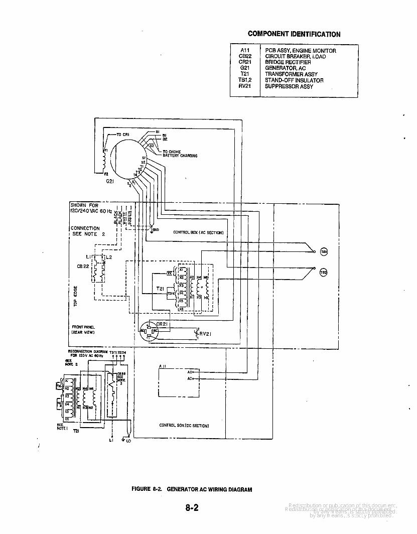
I A1 1 CB22 CR21 G21 T21
RV21 TB1,2
ROHT PANEL (REAR VIEW)
PCB ASSY, ENGINE MONITOR CIRCUIT BREAKER, LOAD BRIDGE RECTIFIER GENERATOR, AC TRANSFORMER ASSY
SUPPRESSOR ASSY STAND-OFF INSULATOR
CONNECTION SEE NOTE 2 I I I
I
RV2 I
i
.
FIGURE 8-2. GENERATOR AC WIRING DIAGRAM
8-2
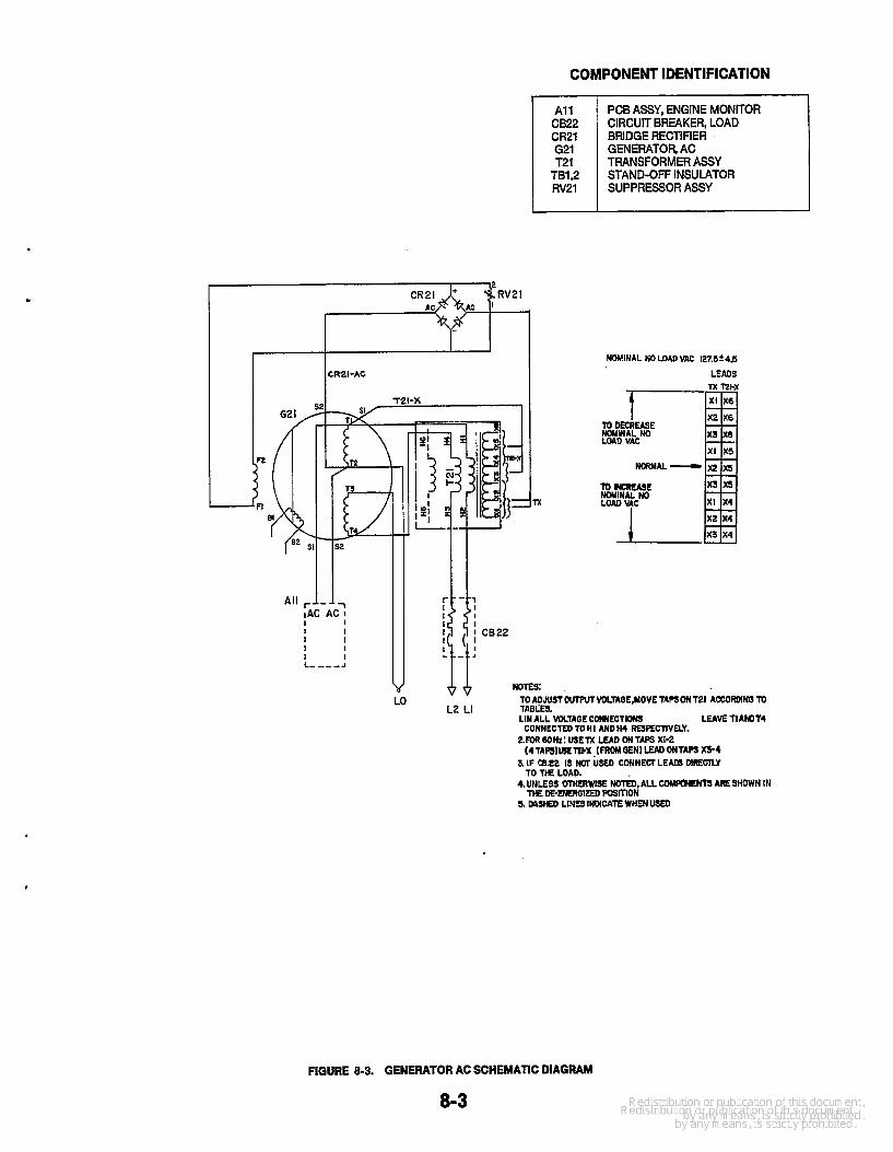
COMPONENT IDENTIFICATION
1 CRZI-AC
A1 1 CB22 cR21 621
TB1,2 RV21
T21
PCB ASSY, ENGINE MONITOR CIRCUIT BREAKER, LOAD BRIDGE RECTIFIER . GENERATOR, AC TRANSFORMER ASSY
SUPPRESSOR ASSY STAND-OFF INSULATOR
x
NOMINAL NOLOADVAC 127.5?4.5
LEADS
TOMCRUSE HOYWAL NO
VAC
x3 x4
TO ADJUST WlRlT VOLTAOL,MOVE TAPSONT21 ACCDRDINB TD TABLES. I.IN ALL WLTAQECOmECTKmS LEAVETIAHIT4
t.FOR6DHz:VSE?%LUDONTIPSXI-2
3. IF CS.22 IS NOT USED CWNECr LEADS DlPEClLY
4.UNLESS UlHfRWlSE &,ALL COMWNCMS AESHOWN IN
5. MSND LINESINC4CATEWHEN~
Lo L2 LI CONNECTED TOHI ANDIH REspEcnvw.
(4 TApSlW W%. [ FROM OENl WD ONTAPS x5.4
TO %E LOAD.
THEDE-D(CRGIZEDPOS~ON
FIGURE 8-3. GENERATOR AC SCHEMATIC DIAGRAM
8-3

REMOTE STARTING CONTROLS Onan has control panel kits available for remotestarting and stopping of the genset The kits vary from a basic single-pole, double-throw, momentary-on switch on up to remote-gauge controls with running time meter, bat- tery condition meter, and engine monitors. The kits come with installation instructions and wiring diagrams for connection.
The control panels are prewired and terminate with a plug connector. See Figure 8-4. Onan has prewired harness assemblies in 15,25, and 45 foot lengths (4.6, 7.6, and 13.7 m) with plug connectors that connect to the generator set control boxand the remote panel. Multiple remote stations are possible with parallel hard-wiring. The genset can be started and stopped from any station, including the set itself. Engine monitor gauges can be used on only one panel (generator set or remote).
If prewired harnesses are not used, number 16-gauge wire is acceptable if runs do not exceed 25 feet (7.6 m) between the remote switch and the genset. Use number 14-gauge wire for longer runs.
-1 lnterchanging connections other ihan shown on the generator set wir-
ing diagrams can cause equipment damage.
BATTERIES General Always use a battery at least as large as specified. The battery should be installed close to the generator set, preferably in a separate compartment The compart- ment must be well ventilated to preventaccumulation of explosive battery gases.
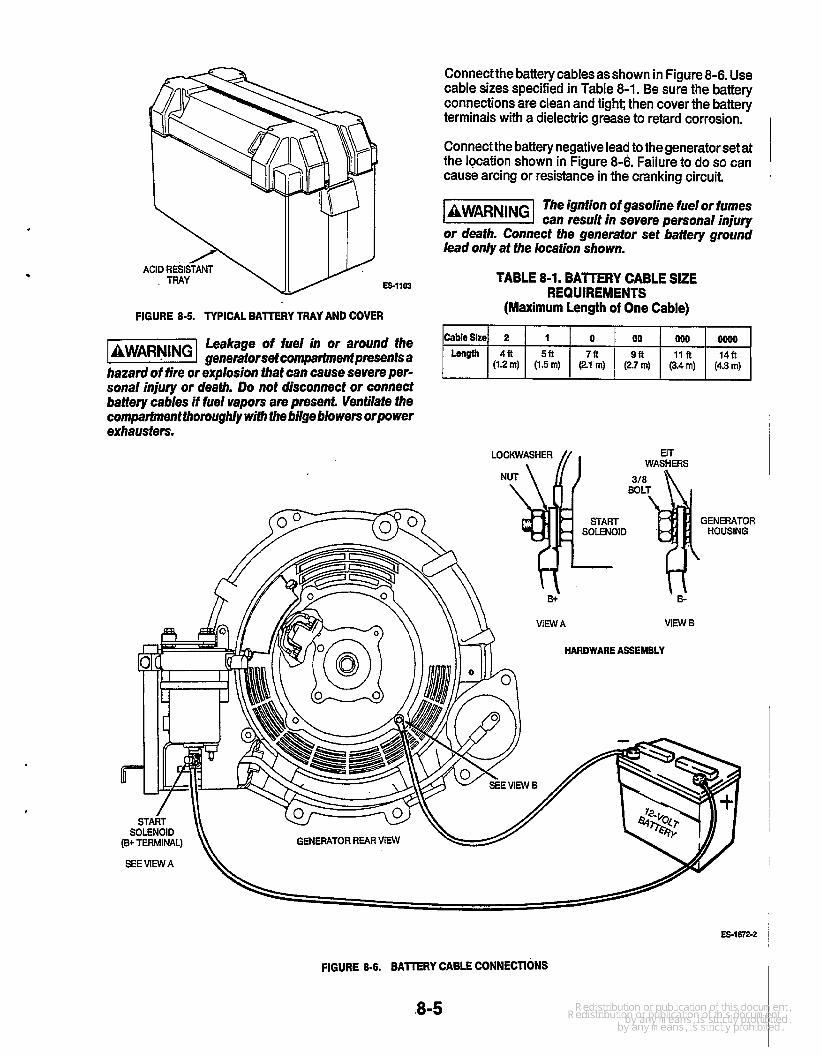
Mount the battery in an acid resistant tray on a platform above the floor. It must be secured to prevent shifting. If mounted in an engine compartment, always install a non-metallic cover to prevent battery damage and arc- ing from accidentally dropped tools. Figure 8-5 shows a typical battery tray and cover.
Maintenance free batteries definitely should be consi- dered for marine application. New technology of these batteries make them completely sealed and mainte- nance free. They usually offer higher output (CCA), bet- ter durability and vibration resistance than other equally priced batteries.
PCB ASSY - ENGINE MONITOR I
TB12 I
11" K12 n 0
GND 1
ES-167c2
FIGURE 8-4. REMOTE CONTROL CONNECTIONS
E S H W
CaMeSize Lengwl
FIGURE 8-5. TYPICAL BAllERY TRAY AND COVER
Leakage of fuel in or around the l3iESl generatorset compartmentpresents a hazard of fire or explosion that can cause severe per- sonal injury or death. Do not disconnect or connect battety cables if fuel vapors are present. Ventilate the comparfment thoroughly with the bilge blowers orpower exhausters.
2 1 0 00 0 o o o o o O 4ft 5ft 7f t
(12 m) (1.5 m) (21 m) (27 m) (3.4171) (4.3m) 9ft 11ft 14ft
Connectthe battery cablesasshown in Figure 8-6. Use cable sizes specified in Table 8-1. Be sure the battery connections are clean and tight; then cover the battery terminals with a dielectric grease to retard corrosion.
Connect the battery negative lead to the generator set at the location shown in Figure 8-6. Failure to do so can cause arcing or resistance in the cranking circuit
The ignfion of gasoline fuel or fumes lZEHEl can result in severe personal injury or death. Connect fhe generafor set battery ground lead only af the Iocation shown.
TABLE 8-1. BAlTERY CABLE SIZE REQUIREMENTS
(Maximum Length of One Cable)
E l i WASHERS
LOCKWASHER
a+- B-
VlEWA VIEW B
HARDWARE ASSEMBLY
ES-1672-2
FIGURE 8-6. BATTERY CABLE CONNECTIONS

Grounding Onan marine generator sets require the batteries con- nected negative ground. Most propulsion engines and vessel electrical equipment have negative ground systems.
BATTERY ACCEPTABLE BATTERY + f 7 w- 0--
The generator set and propulsion engineh must be grounded in accordance with USCG regulation 33CFR183.415. The regulation requires a common ground conductor connected between the generator set and pro- pulsion engine cranking motor circuits. The conductor must be the same size as the largest battery cable. See Figure 8-7.
COMMON CONDUCTOR SAME SIZE AS BATTERY CABLE
d \
The conductor prevents accidental passage of cranking current through the fuel systems and smaller electrical conductors common to the engines. This can happen if a cranking motor ground circuit becomes resistive or opens from corrosion, vibration, bad cable, etc.
GENERATOR SET
rmpmper gtwnd can cause seven? l3BHSl persona/ iniury or death trom fire or explosion. Besun, to installa commongrrxrndconductor hiween all on bead cranking circuiis.
Do not connect the battery negative lead to the generator set at a location other than shown in Figure 8-6.
PROPULSION ENGINE
I
FIGURE 8-7. COMMON GROUND CONDUCTOR
Bonding The generator set must be bonded to the vessel common bonding conductor with a bonding strap as shown in Fig- ure 8-8. If a metallic fuel line is installed between the fuel tank and the generator set shutoff valve, it too must be bonded to the same vessel common conductor.
COMMON BONDING CONDUCTOR Es.1891-I
FIGURE 8-8. BONDING CONNECTlONS
8-6
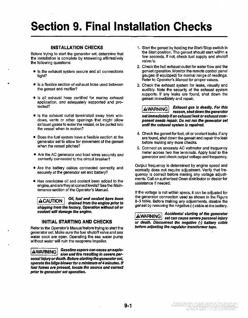
Section 9. Final Installation Checks INSTALLATION CHECKS
Before trying to start the generator set, determine that the installation is complete by answering affirmatively the following questions:
Is the exhaust system secure and all connections tight?
Is a flexible section of exhaust hose used between the genset and muffler?
Is all exhaust hose certified for marine exhaust application, and adequately supported and pro- tected?
Is the exhaust outlet terminated away from win- dows, vents or other openings that might allow exhaust gases to enter the vessel, or be pulled into the vessel when in motion?
Does the fuel system have a flexible section at the generator set to allow for.movement of the genset when the vessel pitches?
0 Are the AC generator and load wires securely and
0
0
correctly connected to the circuit breaker?
Are the battery cables connected correctly and securely at the generator set and battery?
Has crankcase oil and coolant been added to the engine, and are they at correct levels? See the Main- tenance section of the Operator’s Manual.
Oil, fuel and coolant have been drained from the engine prior to
shipping from the factory. Operation wifhouf oil or coolant M I damage fhe engine.
INITIAL STARTING AND CHECKS Refer to the Operator’s Manualbefore trying to start the generator set Make sure the fuel shutoff valve and sea water cock are open. Operating the sea water pump without water will ruin the neoprene impeller.
Gasoline vapors can cause an explo- sion and fire resulting in severe per-
sonal injury or death. Before starting thegenerator set, operate the bilge blower for a minimum ofrlminutes. If fuel fumes are present, locate the source and correct prior to generafor set operation.
1.
2.
3.
4.
5.
Start the genset by holding the StartIStop switch in the Start position. The genset should start within a few seconds. If not, check fuel supply and shutoff valve/s. Check the hull exhaust outlet for water flow and the genset operation. Monitor the remote control panel gauges (if equipped) for normal range of readings. Refer to Operator’s Manual for proper values. Check the exhaust system for leaks, visually and audibly. Note the security of the exhaust system supports. If any leaks are found, shut down the genset immediately and repair.
Exhaust gas is deadly. For this AWARNING reason, shutdown fhegenerafor
set immediatelyifan exhaust leakor exhaustcom- ponent needs repair. Do not run the generator set until the exhaust system is repaired.
Check the genset for fuel, oil or coolant leaks. If any are found, shut down the genset and repair the leak before making any more checks. Connect an accurate AC voltmeter and frequency meter across two line terminals. Apply load to the generator and check output voltage and frequency.
Output frequency is determined by engine speed and normally does not require adjustment Verify that fre- quency is correct before making any voltage adjust- ments. Call an authorized Onan distributor or dealer for assistance if needed.
If the voltage is not within specs, it can be adjusted for the generator connection used as shown in the Figure 8-3 table. Before making any adjustments, disable the genset by removing the negative (-) cable at the battery.
Accidenial starting of the generafor -1 set can cause severe personal injury or death. Disconnect the negative (-) baffery cable before adjusting fhe regulator transformer taps.
9-1

.

Section 10. DC Wiring Diagram
This section contains DC wiring diagram number 612-6539 forthe MCE generator set. Use this dia- gram in conjunction with the wiring information in Section 8 of this manual to make the electrical con- nections necessary to operate the set. *
10-1

SCHEIUTIC - T I I. - A I I K16
K14
dk5
A I I K15
- MTE I I. UNLESS D W R Y I S E MTEO N L CDPCNNTS
ARE SWYN I N T H OE-ENhZW p(IsITICN.
2. DASHED L I K S I M I C A T E WKN EEO.
AC Kl4
U I I I
GM
I ? A
-I , t-2
AI I-R
KII nl
Y
E3.E
cBI2
BT I 81
AI I ENOIN
10-2


Onan Corporation 1400 73rd Avenue N.E. Minneapolis, MN 55432
612-574-5000 International Use Telex: 275477 Fax: 612-574-8087
Onan is a registered trademark of Onan Corporation
1 -800-888-ONAN