Embed Size (px)
Citation preview

WP090529
RF MICRO DEVICES®, RFMD®, Optimum Technology Matching®, and PowerStar® are trademarks of RFMD, LLC. All other trade names, trademarks and registered trademarks are the property of their respective owners. ©2009, RF Micro Devices, Inc.
1 of 217628 Thorndike Road, Greensboro, NC 27409-9421 · For sales or technical support, contact RFMD at (+1) 336-678-5570 or [email protected].
AN RFMD® WHITE PAPER
RFMD.®CATV Hybrid Amplifier Modules: Past, Present, FutureConrad YoungKey Concepts Discussed:
• History of the Cable Industry.
• History of CATV Amplifiers and Hybrid Amplifiers.
• CATV Hybrid Amplifiers Today.
• What the Future Holds.

CATV Hybrid Amplifier Modules: Past, Present, Future
2 of 21WP090529 7628 Thorndike Road, Greensboro, NC 27409-9421 · For sales or technical support, contact RFMD at (+1) 336-678-5570 or [email protected].
ContentsList of Figures. . . . . . . . . . . . . . . . . . . . . . . . . . . . . . . . . . . . . . . . . . . . . . . . . . . . . . . . . . . . . . . . . . . . . . . 3List of Tables . . . . . . . . . . . . . . . . . . . . . . . . . . . . . . . . . . . . . . . . . . . . . . . . . . . . . . . . . . . . . . . . . . . . . . . 3Overview . . . . . . . . . . . . . . . . . . . . . . . . . . . . . . . . . . . . . . . . . . . . . . . . . . . . . . . . . . . . . . . . . . . . . . . . . . . 4A Historical Perspective of the Cable Industry . . . . . . . . . . . . . . . . . . . . . . . . . . . . . . . . . . . . . . . . . . . . . 4
Factors Encouraging Early Growth. . . . . . . . . . . . . . . . . . . . . . . . . . . . . . . . . . . . . . . . . . . . . . . . . . . 5Cable Television Amplifiers (1948-1968) . . . . . . . . . . . . . . . . . . . . . . . . . . . . . . . . . . . . . . . . . . . . . . . . 8The Birth of the CATV Hybrid Amplifier (1968-1974) . . . . . . . . . . . . . . . . . . . . . . . . . . . . . . . . . . . . . . 10Technology Comes of Age (1968-2008) . . . . . . . . . . . . . . . . . . . . . . . . . . . . . . . . . . . . . . . . . . . . . . . . 13CATV Hybrid Amplifiers Today . . . . . . . . . . . . . . . . . . . . . . . . . . . . . . . . . . . . . . . . . . . . . . . . . . . . . . . . . 14What the Future Holds. . . . . . . . . . . . . . . . . . . . . . . . . . . . . . . . . . . . . . . . . . . . . . . . . . . . . . . . . . . . . . . 16
In 2009.... . . . . . . . . . . . . . . . . . . . . . . . . . . . . . . . . . . . . . . . . . . . . . . . . . . . . . . . . . . . . . . . . . . . . . 17In 2010.... . . . . . . . . . . . . . . . . . . . . . . . . . . . . . . . . . . . . . . . . . . . . . . . . . . . . . . . . . . . . . . . . . . . . . 18In 2011.... . . . . . . . . . . . . . . . . . . . . . . . . . . . . . . . . . . . . . . . . . . . . . . . . . . . . . . . . . . . . . . . . . . . . . 19In 2012.... . . . . . . . . . . . . . . . . . . . . . . . . . . . . . . . . . . . . . . . . . . . . . . . . . . . . . . . . . . . . . . . . . . . . . 19
Appendices . . . . . . . . . . . . . . . . . . . . . . . . . . . . . . . . . . . . . . . . . . . . . . . . . . . . . . . . . . . . . . . . . . . . . . . . 20CATV Amplifier Timeline . . . . . . . . . . . . . . . . . . . . . . . . . . . . . . . . . . . . . . . . . . . . . . . . . . . . . . . . . . 20CATV Amplifier Technology Timeline (1948 - 2009). . . . . . . . . . . . . . . . . . . . . . . . . . . . . . . . . . . . 20References . . . . . . . . . . . . . . . . . . . . . . . . . . . . . . . . . . . . . . . . . . . . . . . . . . . . . . . . . . . . . . . . . . . . 20About the Author . . . . . . . . . . . . . . . . . . . . . . . . . . . . . . . . . . . . . . . . . . . . . . . . . . . . . . . . . . . . . . . . 20

3 of 21WP090529
CATV Hybrid Amplifier Modules: Past, Present, Future
7628 Thorndike Road, Greensboro, NC 27409-9421 · For sales or technical support, contact RFMD at (+1) 336-678-5570 or [email protected].
List of FiguresFigure 1. US CATV NTSC Channel Capacity (1948-2008). . . . . . . . . . . . . . . . . . . . . . . . . . . . . . . . . . . . 7Figure 2. Cable Industry Timeline (1948-1988) . . . . . . . . . . . . . . . . . . . . . . . . . . . . . . . . . . . . . . . . . . . 7Figure 3. Typical Frequency Plan, 12-Channel System, One Way (1948-1989) . . . . . . . . . . . . . . . . . . 8Figure 4. Evolution of Jerrold . . . . . . . . . . . . . . . . . . . . . . . . . . . . . . . . . . . . . . . . . . . . . . . . . . . . . . . . . . 8Figure 5. Vacuum Tube Technology: the Jerrold 12-Channel SDA-4 Super Distribution Amplifier . . . 9Figure 6. Vacuum Tube Technology: the Jerrold HPM-12 Channel 12 Amplifier. . . . . . . . . . . . . . . . . . 9Figure 7. Vacuum Tube Technology: the Jerrold HPM-12 Name Plate . . . . . . . . . . . . . . . . . . . . . . . . . 9Figure 8. Simplified Block Diagram of Ideal Push-Pull Hybrid Amplifier . . . . . . . . . . . . . . . . . . . . . . . 10Figure 9. Coffee Can Amplifier with TRW CATV Hybrid Amplifier (c. 1983) . . . . . . . . . . . . . . . . . . . . . 10Figure 10. Exploded View of Typical CATV Hybrid Amplifier . . . . . . . . . . . . . . . . . . . . . . . . . . . . . . . . . 11Figure 11. SOT-115J Package Dimensions . . . . . . . . . . . . . . . . . . . . . . . . . . . . . . . . . . . . . . . . . . . . . . 11Figure 12. Simplified Schematic of Three-Stage GaAs Power Doubler . . . . . . . . . . . . . . . . . . . . . . . . 13Figure 13. GaN-die PD (D10040230PH1) compared to GaAs-die PDs. For CIN versus temperature,
GaN-die PD produces 6dBmV higher RF output.. . . . . . . . . . . . . . . . . . . . . . . . . . . . . . . . . . . 14Figure 14. GaN PD Compared to GaAs PD. CTB versus RF Power Out . . . . . . . . . . . . . . . . . . . . . . . . 14Figure 15. Test Conditions . . . . . . . . . . . . . . . . . . . . . . . . . . . . . . . . . . . . . . . . . . . . . . . . . . . . . . . . . . . 14Figure 16. CATV Hybrid Amplifier Future Development Timeline (2009-2018) . . . . . . . . . . . . . . . . . 16Figure 17. Proposed GREEN PD with Pin 4 Performance Curve Resistor . . . . . . . . . . . . . . . . . . . . . . 17Figure 18. GaAs Die “Last Mile” Fiber Deep HFC Network . . . . . . . . . . . . . . . . . . . . . . . . . . . . . . . . . . 17Figure 19. GaN v.01: Present GaN “Last Mile” Fiber Deep HFC Network: Longer Reach with More
Homes Passed (HP). . . . . . . . . . . . . . . . . . . . . . . . . . . . . . . . . . . . . . . . . . . . . . . . . . . . . . . . . . 18Figure 20. GaN v.02: 1G Green GaN HFC Network . . . . . . . . . . . . . . . . . . . . . . . . . . . . . . . . . . . . . . . . 18Figure 21. GaN v.03: Present GaN Fiber Deep HFC Network: Equivalent GaAs Reach with Lower PDISS
and Fewer Amplifiers. . . . . . . . . . . . . . . . . . . . . . . . . . . . . . . . . . . . . . . . . . . . . . . . . . . . . . . . . 18Figure 22. Next Generation (NG) GaN: 96 Homes Passed Fiber Deep HFC GaN Amplifier-Enabled
“Node+0”. . . . . . . . . . . . . . . . . . . . . . . . . . . . . . . . . . . . . . . . . . . . . . . . . . . . . . . . . . . . . . . . . . 18Figure 23. 1.2GHz Optical Receiver with AGC . . . . . . . . . . . . . . . . . . . . . . . . . . . . . . . . . . . . . . . . . . . . 19List of TablesTable 1.US CATV System Channel Capacity (1948-2008) . . . . . . . . . . . . . . . . . . . . . . . . . . . . . . . . . . . 6Table 2.CATV Systems / Subscribers by Capacity (1989). . . . . . . . . . . . . . . . . . . . . . . . . . . . . . . . . . . . 7Table 3.Manufacturers of 1- to 12-Channel Vacuum Tube Amplifiers Employed in CATV & MATV Sys-
tems (1948-early 1970s) . . . . . . . . . . . . . . . . . . . . . . . . . . . . . . . . . . . . . . . . . . . . . . . . . . . . . . 9Table 4.Manufacturers of 1- to 20-Channel Solid State Transistor Amplifiers for CATV and MATV Sys-
tems (1948-early 1970s) . . . . . . . . . . . . . . . . . . . . . . . . . . . . . . . . . . . . . . . . . . . . . . . . . . . . . 11Table 5.GaN versus GaAs PD Competitive Analysis . . . . . . . . . . . . . . . . . . . . . . . . . . . . . . . . . . . . . . . 14Table 6.CATV Hybrid Amplifier Manufacturers (1948-2009) . . . . . . . . . . . . . . . . . . . . . . . . . . . . . . . . 15Table 7.Fiber Deep HFC Network Comparison by Amplifier Technology . . . . . . . . . . . . . . . . . . . . . . . 17

CATV Hybrid Amplifier Modules: Past, Present, Future
4 of 21WP090529 7628 Thorndike Road, Greensboro, NC 27409-9421 · For sales or technical support, contact RFMD at (+1) 336-678-5570 or [email protected].
OverviewThe year 2008 marks the 40th anniversary of thecommunity antenna television (CATV or “cable”) hybridamplifier packaged in the industry-recognized SOT-115Jpackage. An understanding of the history of the CATVhybrid amplifier and its use within cable networkdistribution amplifiers is necessary to understand today'scable industry and the industry’s future. Improvements indistribution network amplifier technology have beenintegral to the growth of the cable industry, whilelimitations with regard to amplifier technology have, attimes, limited the cable industry's capability to deliverprogramming to its customers. Introduction of the CATVhybrid amplifier in 1968 resulted in the eventualreplacement of vacuum tubes and discrete radiofrequency (RF) transistors used in CATV distributionnetwork amplifiers. Since its inception the CATV hybridamplifier has been the central component in determiningthe capability and performance of CATV distributionequipment. The introduction and continual improvementin performance of the CATV hybrid amplifier has providedthe foundation for the cable industry's continued growthand prosperity since 1968. Today's CATV hybrid amplifieruses the same package as those first used in LindsayBroadband line amplifiers in the early 1970s to providetoday’s Rogers Cable with 35-channel 300MHz capacity.
A Historical Perspective of the Cable IndustryCable distribution amplifier development is intertwinedwith the cable industry's ability to offer new and improvedservices. A complete understanding of the cable industrytoday and the ability to correctly anticipate future trendsdepends partly on knowledge of the cable industry'shistory.
The roots of cable started with the development oftelevision (TV) and the TV broadcasting industry. The TV
broadcasting industry1 developed in densely populatedareas where the substantial number of viewers within thebroadcaster's transmission range made the systemcommercially viable. These areas became known as TV
markets. 2
The electromagnetic spectrum available for allocation tothe TV signal broadcast industry was (and remains)
limited. Unlimited geographic expansion of the TV signalbroadcast service in the US was restricted because of:
1. Questionable commercial feasibility in sparsely pop-ulated areas
2. Signal interference among closely located TV sta-tions sharing channels
The FCC (Federal Communications Commission)allocation of the UHF spectrum (470MHz to 870MHz) tothe TV broadcast industry in 1951 helped alleviate signalinterference problems; however, most early TV receiverswere not equipped with UHF tuners. Viewers needed aseparate UHF antenna for best reception and thecontinuous UHF tuners available at the time were difficultto use. In the 1960s, population centers of less than50,000 almost certainly had no TV broadcast station.Somewhat larger population centers may have had one,but only large population centers had affiliate TVbroadcast stations for all three major networks and PBS(Public Broadcasting Service). As a result of these factors,reception in areas outside the major markets was poor,incomplete, or nonexistent.
Thus, the cable industry was born to fulfill a need forimproved reception of TV signals in smaller populationcenters. The electromagnetic spectrum allocated tobroadcast TV relied primarily on line-of-sight propagationmodes. For this reason, signal reception was significantlyenhanced by using elevated mast antennas with gooddirectivity. By sharing the cost of a well-designed and well-positioned antenna (in an early form of "head end" (HE))and distributing these higher signal-to-noise signals viatwin lead antenna wire ("ladder wire") at first and followedby the use of coaxial cable (forming the earliest"distribution system" or "cable plant"), communities wereable to upgrade their TV signal reception. These systemssoon became known as CATV. In 1948, John andMargaret Walson of Mahanoy City, Pennsylvania, built oneof the first CATV systems to increase TV receiver sales intheir appliance store.
Except in isolated cases, the typical early CATV systemprovided a community with an affiliate's signal for eachmajor TV network, a PBS station, and one or two
1. The broadcasting of a United States National Television System Committee (NTSC) television signal started in 1946.
2. Markets are known as Designated Market Areas, as defined by Nielsen Media Research. In 2008 the largest market is New York City with 7,391,940 TV households, the smallest market is Glendive, Montana, with 3,890 TV households (down from 5,300 in 1987). (http://www.nielsenmedia.com/nc/nmr_static/docs/2007-2008_DMA_Ranks.xls)
5 of 21WP090529
CATV Hybrid Amplifier Modules: Past, Present, Future
7628 Thorndike Road, Greensboro, NC 27409-9421 · For sales or technical support, contact RFMD at (+1) 336-678-5570 or [email protected].
independent stations. In many cases, the signal-to-noiseratio at a TV receiver was poor for distant transmitters.Co-channel signal interference was often a problembecause some locations were nearly equidistant fromstations sharing the same channel. Variations inpropagation conditions caused intermittent signalinterference. Signal reception quality often variedconsiderably among channels, depending upon distancebetween the TV receiver and the tuned stationtransmitter. Taller and higher performance antennashelped overcome these difficulties to a degree; however,the justifiable expense and the performance of early CATVsystems matched the size of the customer base.
CATV systems from 1948 through the 1960s weretypically small, independently owned “mom and pop"operations. In some cases, they were literally one-personoperations. In those days, small towns were the primarymarket for CATV. Isolated dwellings in rural areas weredifficult to serve because of the expense andperformance of long coaxial cable runs.
From the industry's infancy in the early 1950s to 1965,the number of CATV subscribers grew to approximately1,500,000, representing only a small fraction of total TVhouseholds. CATV remained in the background ofnational attention and simply provided a technique forextending the coverage of TV broadcasts. Although a fewTV broadcasters foresaw competition from the CATVindustry, most were indifferent toward CATV in its earlydays.
Factors Encouraging Early GrowthFactors encouraging the cable industry's earliest growthperiod between 1948 and 1954 were:
1. The first NTSC broadcast in 1946 and the subse-quent introduction of broadcast TV in select mar-kets.
2. World War II (WWII) provided both the technical training and initial key hardware (war surplus) to fuel the cable industry. Many early cable industry pio-neers were trained as a result of direct military ser-vice or service within the defense industry during WWII. WWII accelerated the advent of radar and advanced radio frequency (RF) communications techniques with associated hardware (twin lead cable, RG11U coaxial cable, vacuum tube amplifi-ers, and electron tube amplifiers). The GI Bill pro-vided the means for many early cable pioneers to receive the education required to become contribu-tors to the cable industry's early technical accom-plishments and growth.
3. The master antenna television (MATV) market helped accelerate the development of hardware and broadcast TV signal reception enhancement tech-niques that benefited the CATV industry. Examples include Jerrold Electronics' initial use of coaxial cable to connect multiple TV receivers within multi-ple dwelling units (MDUs) and commercial buildings; TV receiver boosters (such as the Jerrold MUL-TV preamplifier inserted between a MATV antenna and TV receivers within apartment houses; Blonder-Tongue Laboratories broadband TV antenna booster) equipped with variable very high frequency (VHF) tuners with channel 2 through 13 capability that amplified broadcast TV signals at an individual TV receiver; vacuum tube based "stagger-tuned" strip amplifiers manufactured by companies such as Alliance, Benco, Blonder-Tongue Laboratories, Elec-tro Voice, Jerrold, RCA, and SKL.
4. After World War II, the mass development of televi-sion was delayed by a six-month moratorium on the issuing of television broadcasting licenses by the Federal Communications Commission (FCC). That six-month moratorium was designed to let the FCC essentially draw a road map for itself on where it wanted television to go. Making the decisions of where to go was more complicated than previously thought and the six-month moratorium was extended to four years. This became known as the era of the Big Freeze. The FCC placed a moratorium on the issuance of new broadcast TV transmitter licenses nationwide (due to co-channel interference issues) in the period 1948 through 1952. In 1952, the FCC released procedures for administering licenses under their 1952 amendments with "Provi-sions Governing the Granting, Renewal and Transfer of Construction Permits and Licenses."
5. In 1948, there were 16 broadcast TV stations oper-ating on the air. By 1953, there were 126.
6. Direct US government (FCC) regulation of the cable industry did not begin until 1958.
7. AT&T permitted the lease, by contract, of utility poles required to mount early CATV distribution network amplifiers. Both TV broadcasters and AT&T falsely assumed that once the 1948 FCC moratorium on broadcast TV transmitter licenses was lifted that the burgeoning CATV industry would wither and die. Con-ventional wisdom within the TV broadcast commu-nity in 1952 was that every US citizen would soon have access to over-the-air TV signals within a few years. The reality is that even today there are many locations within the US that still do not have full TV

CATV Hybrid Amplifier Modules: Past, Present, Future
6 of 21WP090529 7628 Thorndike Road, Greensboro, NC 27409-9421 · For sales or technical support, contact RFMD at (+1) 336-678-5570 or [email protected].
broadcast coverage (all major affiliate signals, plus PBS).
Early cable systems from 1949 to the early 1960sconsisted of tower-mounted antennas with preamplifiersthat drove flexible coaxial cable with dispersed vacuumtube amplifiers. These systems employed little or no HEsignal processing and did not require set-top converters.The TV receiver was simply tuned to a channel providedby the coaxial cable, as if tuning to a channel broadcastoff-air using VHF channels 2 through 13. CATV systemsnaturally evolved into well-defined segments: HE,distribution (the CATV or cable plant), and subscriber(customer premises) equipment.
In areas where TV signals were available from more thanthree or four TV broadcast stations, CATV systems couldoften receive TV broadcast stations on adjacent allocatedchannels. Because some or all broadcast stations weredistant, propagation conditions caused the received TVsignal levels to vary independently. When adjacentchannels were occupied, the TV receiver only functionedproperly if the TV signal levels on these channels werewithin ±3dB of the tuned channel. If a TV broadcaststation's signals were stronger than those of other nearbybroadcast stations, frequency selective networks wereused to attenuate the stronger channel and thus equalizethe TV signal levels.
Simple frequency selective networks did not, however,correct for propagation-induced signal level variations. Tobetter maintain constant signal levels on each channel,signal processors with intermediate frequency (IF)automatic gain compensating (AGC) networks wereintroduced. Signal processors were also used to translateUHF stations into the VHF spectrum for carriage on theCATV system. These and other factors, such as thesubstitution of standby carriers for lost carriers,automatic program origination, and improved satellitetechnology, initiated the evolution of the complex HEsystems used today.
The mid-band spectrum from 88MHz to 174MHz betweenNTSC channels six and seven was allocated for FM radiobroadcast, aeronautical, and mobile two-way services.This spectrum could have been used on closed CATVsystems except for two problems:
1. Early distribution amplifiers were single-ended, which resulted in a buildup of second order distor-tion beats in the mid-band channels.
2. The TV receiver did not tune mid-band channels.
Practical, high frequency, solid state, bipolar transistorsbecame available in the early 1960s and led toimprovements in distribution amplifier design. In the late1960s push-pull amplifier circuitry was used to greatlyreduce second order distortion. The development of theset-top converter eventually overcame the TV receiverlimitations.
The need to use the mid-band spectrum led to thedevelopment of the set-top converter by Jerrold and Alps.Some CATV systems imported signals by terrestrialmicrowave links. This allowed these systems to provideadditional programming, which enhanced theirmarketability. By 1974, numerous independent TVbroadcast stations were in operation, thus increasing thenumber of broadcast stations CATV systems could carry.Though the 216MHz CATV system popularly in placethrough the early 1970s was capable of carrying 12 NTSCchannels, the average CATV system actually carried sevenchannels of programming until the mid-1970s.
Table 1. US CATV System Channel Capacity (1948-2008)
Year NTSC Channel Capacity
Upper Frequency Limit (MHz)
1948 3 162a
a. Includes 90MHz for FM radio and other restricted-use frequencies.
1949 5 174a
1950 8 192a
1951 12 216a
1974 35 264
1980 52 378
1988 83 552
1992 91 600
1993 116 750
1995 136 870
2000 158 1002
2008 179 1128

7 of 21WP090529
CATV Hybrid Amplifier Modules: Past, Present, Future
7628 Thorndike Road, Greensboro, NC 27409-9421 · For sales or technical support, contact RFMD at (+1) 336-678-5570 or [email protected].
Figure 1. US CATV NTSC Channel Capacity (1948-2008)
By 1975, CATV system technology had matured. HEsystems resembled the form, functions, and performanceof pre-1995 hybrid fiber coaxial (HFC) cable systems. TheCATV hybrid amplifier, now the cornerstone component inmodular distribution optical nodes and amplifiers, waswell established. Two-way CATV technology was wellunderstood. During the 1970s, 30-channel, 300MHzcomponents became readily available, but the embeddedbase of installed CATV systems primarily consisted of 12-channel, 216MHz systems. As late as 1988, 17% of CATVsystems were only 12-channel capable and served 4% ofall cable subscribers.
Source: Cable Television Developments (Washington, D.C.: National Cable Television Association, May 1989)
By the late 1950s TV broadcasters knew the cable andbroadcasting industries competed. In 1958, the FCCbegan regulating CATV. To protect TV broadcasting, theFCC created must-carry rules in 1972. These rulesrequiring cable companies carry various local and publicTV stations within a cable provider's service area havehad a dramatic history. Designed to ensure local stationsdid not lose market share with increased competitionfrom cable networks competing for a limited number ofcable channels, must-carry rules have at times been ruledunconstitutional and gone through numerous changes. Tofurther protect TV broadcasting, the FCC enactedimportation rules in 1972. These rules prevented CATVsystems from importing the TV signals of more than onedistant affiliate (such as an affiliate outside the areacovered by the cable system) if the correspondingnetwork had an affiliate in the CATV system coveragearea. The FCC also limited the number of independentbroadcast stations that could be imported. The FCCreduced the extent of the importation rules in 1981.
Figure 2. Cable Industry Timeline (1948-1988)
Freq (MHz)
0
200
400
600
800
1000
1200
0 50 100 150 200
NTSC Channels
F (M
Hz)
Freq (MHz)
Table 2. CATV Systems / Subscribers by Capacity (1989)
Channel Capacity
Systems % Of Systems
% Of Subscribers
54 or more 679 7.53 20.53
30 - 53 4502 49.93 66.25
20 - 29 1420 15.75 8.87
13 - 19 292 3.24 0.61
6 - 12 1202 13.33 2.22
5 31 0.34 0.01
Fewer than 5 7 0.08 0.01
Not Available 883 9.80 1.50
TOTAL 9016 100.00 100.00
Technology
1st
CableSystem
SetTop
Converters
300 MHzBW
2-WaySystems
Pay
1st
CableTVROs
400 MHzBW
FeedForwardAmplifiers
550 MHzBW
TVROScrambling
Competition
CableSubscribers
(M)
VCRsIn Use
(M)
0.03 0.45 0.95 2.8 7.3 13 25 43
Regulation
1948
1ST HBOService
0.03 0.6 8.4 48
16 126
1953
523
1958
625
1963
785
1968
927
1973
982
1ST
BackyardTVROs
1978
FCCInitiates
DBS
1106
1983
1362
DBSFlounders
BackyardTVROMktDies
FCCBegins
RegulatingCable
Must-CarryOverturned
FCC Prohibits Cable In 100Major Mkts
FCC Lifts CableBan In 100Major Mkts
2-WayRequired For New Builds
2-WayRuling
Overturned
CableActOf
1984
Cable ActOf
1984Rates
Deregulated
1st CATV Hybrid Amplifier
1988
VHF & UHFHigh PowerTV Stations

CATV Hybrid Amplifier Modules: Past, Present, Future
8 of 21WP090529 7628 Thorndike Road, Greensboro, NC 27409-9421 · For sales or technical support, contact RFMD at (+1) 336-678-5570 or [email protected].
Cable Television Amplifiers (1948-1968)Early cable systems consisted of tower-mountedantennas with preamplifiers that drove flexible coaxialcable with dispersed vacuum tube amplifiers. The firstcable systems were 12-channel forward path only(Figure 3) and the frequency plan was based oncharacteristics of VHF television receivers manufacturedin the US from 1948 to the late 1970s. These earlysystems employed little or no HE signal processing anddid not require set-top converters. The TV receiver wassimply tuned to a channel provided by the coaxial cable,as was done when tuning to a TV channel broadcast off-air (VHF channels 2 through 13). Cable systems naturallyevolved into well-defined segments consisting of HE,distribution (the cable plant), and subscriber (customerpremises) equipment. These cable systems carried FMradio on 88MHz to 108MHz and the 108MHz to 174MHz(known as mid-band) range was unoccupied to maintainconsistency with television signal broadcast standards.
In areas where TV signals were available from more thanthree or four TV broadcast stations, CATV systems couldoften receive broadcast stations on adjacent allocatedchannels. Because some or all TV broadcast stationswere distant, propagation conditions caused the receivedTV signal levels to vary independently.
Figure 3. Typical Frequency Plan, 12-Channel System, One Way (1948-1989)
The original 12-channel cable system amplifiers usedvacuum tubes. The triode Audion (three-electron) vacuumtube amplifier, invented and patented by Lee de Forest in1907, boosted the amplitude of radio waves as they werereceived, allowing the human voice, music, or anybroadcast signal to be heard loud and clear. The vacuumtube became the key component of all radio, telephone,television, computer systems, and radar before theinvention of the transistor in 1947. The earliest highperformance cable television amplifiers were developedusing surplus military vacuum tubes and associatedpower supplies. Milton Jerrold Shapp developed a systemin 1948 that allowed one master antenna to provide asignal to all TVs in a department store in Philadelphia,Pennsylvania. Shapp's system was notable because itemployed coaxial cable (from military surplus) and self-made signal boosters (amplifiers constructed usingsurplus military triode vacuum tubes) capable of carrying
multiple signals at once with high fidelity. Shapp iscredited with establishing the first commercially viableMATV systems. In 1948, Shapp formed a company,Jerrold, to manufacture, sell, install, and support hisMATV hardware in the eastern United States. At nearly thesame time, John and Margaret Walson installed the first(CATV) system in Mahanoy City, Pennsylvania, to facilitatethe sale of newly introduced General Electric (GE) TVs attheir Service Electric appliance store. The Walsonsformed Service Electric Cable TV Incorporated in 1948,still operating today as Service Electric Cablevision, theoldest cable TV multiple system operator (MSO) in the US.The Walson's charged $100 installation fee plus $2 amonth for delivering two to three Philadelphia broadcastTV network signals to TVs sold by the Walsons. TheWalson's first CATV system used ladder wire (twin-leadantenna wire) and homemade amplifiers. After theWalsons established their CATV system, Bob Tarlton builtthe first CATV system in Lansford, Pennsylvania, with theexpress purpose of charging a monthly fee for service(earlier systems were constructed by TV set retailers tofacilitate the sale of TV sets). Tarlton modified JerroldMATV booster amplifiers and used them to amplify hisCATV system signals. When Milton Shapp visited Lansfordand saw Tarlton's CATV system, he returned toPhiladelphia, restructured his company to serve the newCATV business, and quickly became the largest and mostimportant CATV equipment supplier in the US. Bob Tarltonjoined Jerrold and became a key contributor to Jerrold'sgrowth as both a cable TV industry equipment supplier,and multinational, far-reaching MSO. The company thatwas once Jerrold is now part of Motorola's broadbandbusiness operated from Horsham and Hatboro,Pennsylvania, among other worldwide locations.
Figure 4. Evolution of Jerrold
2
54 MHz
LOW BAND
3 4
72 76
5 6
FM
88 108 174
7 8 9 1110 12 13
216
HIGH BAND
Formed by Milton Jerrold Shapp in 1948
Purchased by GI in 1967 for $129M
Purchased by Motorola in 2000

9 of 21WP090529
CATV Hybrid Amplifier Modules: Past, Present, Future
7628 Thorndike Road, Greensboro, NC 27409-9421 · For sales or technical support, contact RFMD at (+1) 336-678-5570 or [email protected].
Figure 5. Vacuum Tube Technology: the Jerrold 12-Channel SDA-4 Super Distribution Amplifier
Source: http://theoldcatvequipmentmuseum.org
Figure 6. Vacuum Tube Technology: the Jerrold HPM-12 Channel 12 Amplifier
Source: http://theoldcatvequipmentmuseum.org
Figure 7. Vacuum Tube Technology: the Jerrold HPM-12 Name Plate
Source: http://theoldcatvequipmentmuseum.org
Table 3. Manufacturers of 1- to 12-Channel Vacuum Tube Amplifiers Employed in CATV & MATV Systems (1948-early 1970s)
Company Name
Notes
Alliance The Alliance Manufacturing Company, Alliance, Ohio.
Astatic Manufactured the AT-1 All Channel Television Booster.
Benco Benco Television Associates, Limited, Toronto, Canada.
Blonder Tongue Laboratories
Established in 1950 in Westfield, New Jersey, by Isaac (Ike) S. Blonder and Benjamin (Ben) H. Tongue to develop, sell, install, and support MATV broadband TV antenna boosters (vacuum tube-based amplifiers) connecting individual dwell-ing units in apartments and hotels to a master antenna, typically on the roof of each building. Still a CATV and MDU equipment supplier to the worldwide CATV/SATCOM industry today.
Community Equip-ment Company
(aka Community Engineering Corpo-
ration) - CECO
Owned and operated by Haller, Raymond, and Brown (HRB), State College, PA, incorporated as C-Cor in 1953 (due to the CECO name copyright infringement). C-Cor acquired by Arris Corporation in 2007.
Electro Voice Electro Voice Incorporated, Buchanan, Michigan. Became well known for professional audio equipment, including horn-loaded loudspeakers and audio amplifiers.
Entron Acknowledged to have introduced the first five-channel broadband amplifier with linear (low cross-modulation) perfor-mance.
Jerrold Company formed by Milton Jerrold Shapp, later a two-time Governor of Pennsylvania, in 1948 to develop, sell, install, and support MATV system hardware. Enabled and dominated early CATV and MATV equipment industries and became a significant MSO and CATV test equipment manufacturer.
RCA Radio Corporation of America, formed by David Sarnoff, acknowledged by many as the father of the present day televi-sion broadcast industry.
SKL Spencer-Kennedy Laboratories, Boston, Massachusetts.
CATV Hybrid Amplifier Modules: Past, Present, Future
10 of 21WP090529 7628 Thorndike Road, Greensboro, NC 27409-9421 · For sales or technical support, contact RFMD at (+1) 336-678-5570 or [email protected].
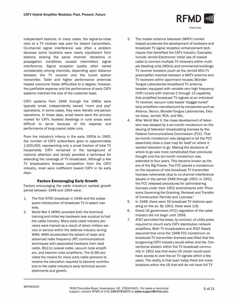
The Birth of the CATV Hybrid Amplifier (1968-1974)Starting in the early 1960s, semiconductors began tosupplant vacuum tube technology within CATV and MATVamplifiers. Expansion beyond the 12-channel systemrequired the development of push-pull amplifier circuitryto minimize second order distortion. The cascade push-pull amplifier configuration typically incorporates four (4)transistors. Figure 8 is a simplified block diagram of anideal push-pull amplifier.
Figure 8. Simplified Block Diagram of Ideal Push-Pull Hybrid Amplifier
Source: William "Bill" Lambert, "Second-Order Distortion in CATV Push-Pull Amplifiers," Proceedings of the IEEE,
Vol. 58, No. 7, 1970. Created while Bill was employed by Jerrold Electronics Corporation, Willow Grove, PA.
In the period 1963 through the late 1970s, most CATVand MATV amplifiers, designed to boost broadcast TVantenna signals or provide video via extended distancecascades, used solid state discrete transistor-basedamplifiers. The advantages of solid state transistor-basedCATV and MATV amplifiers versus vacuum tube-basedamplifiers included:
• lower input voltage (from life-threatening voltages in the hundreds of volts required to drive vacuum tubes, to <30Volts DC)
• cheaper, smaller power supplies
• increased reliability
• smaller amplifier housings
• lower cost
Disadvantages compared to vacuum tube-equippedamplifiers included:
• limited number of transistor suppliers
• new methods required for cooling both the transistor devices and amplifier housings
• need to invent transient voltage protection techniques,
technology, and installation
• field replacement of discrete transistors soldered to printed circuit boards was not practical
A key advantage that CATV hybrid amplifiers have enjoyedover discrete transistors and other packaged amplifiersolutions is ease of field replacement: only a screwdriveris required. The SOT-115J is designed with easilyaccessible pins for CATV and MATV amplifier pin andsocket insertion and removal without need for soldering.
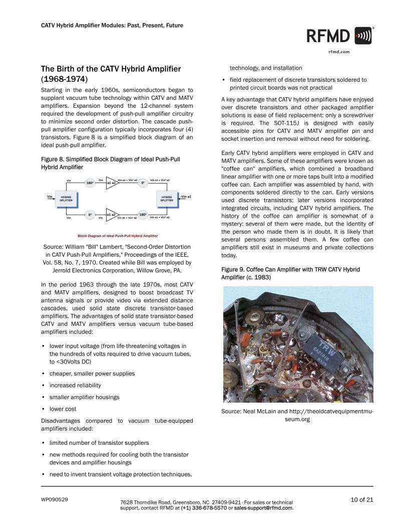
Early CATV hybrid amplifiers were employed in CATV andMATV amplifiers. Some of these amplifiers were known as"coffee can" amplifiers, which combined a broadbandlinear amplifier with one or more taps built into a modifiedcoffee can. Each amplifier was assembled by hand, withcomponents soldered directly to the can. Early versionsused discrete transistors; later versions incorporatedintegrated circuits, including CATV hybrid amplifiers. Thehistory of the coffee can amplifier is somewhat of amystery: several of them were made, but the identity ofthe person who made them is in doubt. It is likely thatseveral persons assembled them. A few coffee canamplifiers still exist in museums and private collectionstoday.
Figure 9. Coffee Can Amplifier with TRW CATV Hybrid Amplifier (c. 1983)
Source: Neal McLain and http://theoldcatvequipmentmu-seum.org
HYBRIDSPLITTER
180º
0º
Vin
Vin
Vin
Vin
-Vin
180º
0º
HYBRIDSPLITTER
-Vin a1
a1 a2
a1 a2Vin a1 + Vin² a2
-Vin a1 + Vin² a2
-Vin a1 + Vin² a2
Vin a1 + Vin² a2
Block Diagram of Ideal Push-Pull Hybrid Amplifier

11 of 21WP090529
CATV Hybrid Amplifier Modules: Past, Present, Future
7628 Thorndike Road, Greensboro, NC 27409-9421 · For sales or technical support, contact RFMD at (+1) 336-678-5570 or [email protected].
In the early 1970s, TRW Semiconductor introduced to theCATV market what is today the standard package andhybrid circuitry for cable television system amplifiers.Development of the CATV hybrid amplifier as we know ittoday began at TRW in 1968. The aluminum heat sinkemployed as the transistor die and thin film circuit baseplate in the SOT-115J (a non-JEDEC standard designationwhich is generally accepted today to describe thestandard CATV hybrid amplifier package) was derived byremoving the feet from a 1960s era metal chair.
Figure 10. Exploded View of Typical CATV Hybrid Amplifier
Source: Excerpt from IEEE Transactions on Cable Televi-sion, Vol. CATV-3, No. 1, January 1978. "Reliability Consid-erations in CATV Hybrids," by Al Grant and Jim Eachus of
Motorola Semiconductors.
CATV hybrid amplifiers in the period from 1968 to themid-1990s employed transistors based on silicon bipolarprocesses. Many CATV hybrid amplifiers available in theSOT-115J package and designed for upstream (returnpath) frequencies (typically 5MHz to 200MHz) stillemploy silicon bipolar amplifier die today. “CATV AmplifierTimeline” on page 20 details the development andmanufacturer's histories of the SOT-115J packaged hybridamplifier.
Figure 11. SOT-115J Package Dimensions
Table 4. Manufacturers of 1- to 20-Channel Solid State Transistor Amplifiers for CATV and MATV Systems (1948-early 1970s)
Company Name
Notes
Ameco Introduced the NO STEP amplifier in 1963 for CATV cascades employing solid state transistor amplifiers (no vacuum tubes). NO STEP nomenclature came from the stencil used by Ameco to warn installers and cable TV technicians not to step on the amplifier housing.
Blonder Tongue Laboratories
Established in 1950 in Westfield, New Jersey, by Isaac (Ike) S. Blonder and Benjamin (Ben) H. Tongue to develop, sell, install, and support MATV broadband TV antenna boosters (vacuum tube-based amplifiers) connecting individual dwelling units in apartments and hotels to a master antenna, typically on the roof of each building. Still a CATV and MDU equipment supplier to the worldwide CATV/SATCOM industry today.
C-Cor Owned and operated by Haller, Raymond, and Brown (HRB), State College, PA, incorporated as C-Cor in 1953 (due to the CECO name copyright infringement). C-Cor acquired by Arris Corporation in 2007.
Jerrold Company formed by Milton Jerrold Shapp, later a two-time Governor of Pennsylvania, in 1948 to develop, sell, install, and support MATV system hardware. Enabled and dominated early CATV and MATV equipment industries and became a signif-icant MSO and CATV test equipment manufacturer.
Sylvania Sylvania's CATV amplifier division acquired by Texscan in the 1980s.
Theta-Com Wholly owned subsidiary of Texscan.
Vikoa Founded in 1955 by Arthur Baum.
123 5 7 89
R
O
Q
M
5 10mm0
scale
B
N
L
F
A
D
H
øG
T
S PJ
U
I
EC
K
1 2 3 4 5 6 7 8 9
INP
UT
GN
D
GN
D
+VB
GN
D
GN
D
OU
TPU
T
Pinning:
min maxA 44,4 44,8B 13,4 13,8C 19,9 20,9D 7,85 8,15E 12,45 12,75F 37,9 38,3G 3,95 4,2H 3,8 4,2I 25,2 25,6J - -K 4,0 4,4L 27,0 27,4M 11,1 12,1N 5,4 6,2O 0,23 0,27P 0,42 0,48Q 2,24 2,84R 2,04 3,04S 2,29 2,79T 4,83 5,33U 4,83 5,33
nominal44,6 ± 0,2
13,6 ± 0,2
20,4 ± 0,5
8 ± 0,15
12,6 ± 0,15
38,1 ± 0,2
4 ± 0,2
25,4 ± 0,2
4 +0,2 / -0,05
UNC 6-324,2 ± 0,2
27,2 ± 0,2
11,6 ± 0,5
5,8 ± 0,4
0,25 ± 0,02
0,45 ± 0,03
2,54 ± 0,3
2,54 ± 0,5
2,54 ± 0,25
5,08 ± 0,25
5,08 ± 0,25
All Dimensions in mm:
EuropeanProjection
Notes:
CATV Hybrid Amplifier Modules: Past, Present, Future
12 of 21WP090529 7628 Thorndike Road, Greensboro, NC 27409-9421 · For sales or technical support, contact RFMD at (+1) 336-678-5570 or [email protected].
Until the mid-1970s, when Motorola Semiconductorsintroduced its first CATV hybrid amplifier, TRWSemiconductors was the sole supplier of CATV hybridamplifiers.
Rogers Cable of Canada adopted the TRW CATV hybridamplifier as the central amplifier technology within its300MHz downstream upper frequency-capable (35downstream NTSC channels) trunk, bridger, and lineextender (LE) CATV amplifiers in 1973. Rogers installed300MHz 35-channel NTSC cable systems throughoutCanada from 1973 to 1980. Rogers also used the TRWCATV hybrid amplifier in 300MHz-capable systemsinstalled in Europe from 1974 to 1980.
13 of 21WP090529
CATV Hybrid Amplifier Modules: Past, Present, Future
7628 Thorndike Road, Greensboro, NC 27409-9421 · For sales or technical support, contact RFMD at (+1) 336-678-5570 or [email protected].
Technology Comes of Age (1968-2008)Cable equipment manufacturers from 1968 to the early1990s specialized in the construction of highperformance trunk, bridger, and line extender amplifiers,as well as the internal functions of these amplifiers,enabling long distance cable system cascades. Likewise,CATV hybrid amplifier and semiconductor manufacturershave specialized in hybrid amplifiers with minimal noiseand distortion. The parallel development of hybridamplifier techniques and higher performance trunk,bridger, and line extender amplifiers made possible theincreased channel capacity and bandwidth of moderncable systems.
Since the introduction of the first HFC optical node by ONIin 1986 and the installation of HFC networks beginning inthe early 1990s, CATV hybrid amplifier performancerequirements have steadily increased. The CATV powerdoubler (known as the “parallel hybrid” at the time of itsintroduction by Amperex in 1984 and registered byMagnavox/Philips as the "power doubler" in the late1980s) has enabled the implementation of HFC networkswithout traditional trunk and bridger amplifiers whilesimultaneously reducing the number of installedtraditional line extender amplifiers. HFC networks with"fiber deep" capability, where the optical node is placed towithin 1.5km or closer to end customer houses or MDUs,is feasible as a result of the ever-increasing performanceof the CATV hybrid amplifier power doubler.
Semiconductor technology has made significant progressbetween 1968 and today. Gallium arsenide (GaAs)-baseddie were introduced into prototype CATV hybrid amplifiersin the early 1990s. Early GaAs die-equipped CATV hybridamplifiers demonstrated questionable performanceadvantage versus the best silicon bipolar based hybridsof the era. However, semiconductor manufacturersembarked on a continuous improvement effort and, bythe early 2000s, GaAs die-equipped hybrids hadsurpassed silicon bipolar-based hybrids in everymeaningful performance measurement, includingbandwidth to 1GHz, multi-carrier distortion (CSO, CTB,XMOD, CIN), RF output power, and power efficiency.
Steady improvement has been made in the design andmanufacture of the magnetics components required toimplement CATV hybrid amplifiers. Figure 8 is a simplifiedblock diagram of an ideal push-pull hybrid amplifier. Thedesign of an ideal push-pull hybrid amplifier (as shown inFigure 8) requires an ideal set of hybrid splitters. In the1970s most suppliers that constructed amplifiersattempting to leverage the advantages of the push-pull
architecture fell short of desired performance levels,primarily due to inadequate hybrid splitter performance.
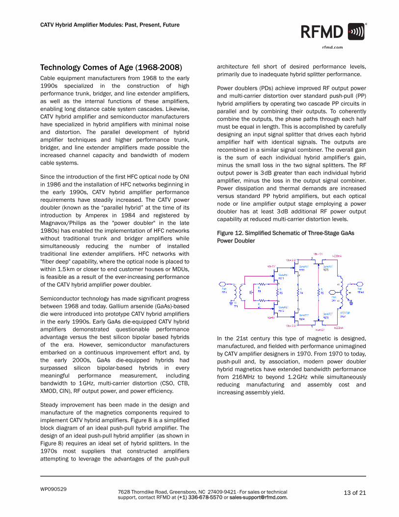
Power doublers (PDs) achieve improved RF output powerand multi-carrier distortion over standard push-pull (PP)hybrid amplifiers by operating two cascade PP circuits inparallel and by combining their outputs. To coherentlycombine the outputs, the phase paths through each halfmust be equal in length. This is accomplished by carefullydesigning an input signal splitter that drives each hybridamplifier half with identical signals. The outputs arerecombined in a similar signal combiner. The overall gainis the sum of each individual hybrid amplifier's gain,minus the small loss in the two signal splitters. The RFoutput power is 3dB greater than each individual hybridamplifier, minus the loss in the output signal combiner.Power dissipation and thermal demands are increasedversus standard PP hybrid amplifiers, but each opticalnode or line amplifier output stage employing a powerdoubler has at least 3dB additional RF power outputcapability at reduced multi-carrier distortion levels.
Figure 12. Simplified Schematic of Three-Stage GaAs Power Doubler
In the 21st century this type of magnetic is designed,manufactured, and fielded with performance unimaginedby CATV amplifier designers in 1970. From 1970 to today,push-pull and, by association, modern power doublerhybrid magnetics have extended bandwidth performancefrom 216MHz to beyond 1.2GHz while simultaneouslyreducing manufacturing and assembly cost andincreasing assembly yield.

CATV Hybrid Amplifier Modules: Past, Present, Future
14 of 21WP090529 7628 Thorndike Road, Greensboro, NC 27409-9421 · For sales or technical support, contact RFMD at (+1) 336-678-5570 or [email protected].
CATV Hybrid Amplifiers TodayThe introduction in 2008 of the first Gallium Nitride (GaN)die-based CATV hybrid amplifiers (1GHz bandwidth 20dBand 23dB gain power doublers from RFMD) has heraldedthe next generation of CATV hybrid amplifiers. For the firsttime in the history of CATV amplifier development,network system designers have the option to employ CATVhybrid power doublers within optical nodes and lineamplifiers that can simultaneously produce twice the RFoutput power (an increase of 6dBmV) with an order ofmagnitude (10dB) decrease in carrier intermodulation
noise3 (CIN) over temperature without increasingdissipated power as compared to the world's bestavailable GaAs die-equipped power doubler. Figure 13illustrates this performance comparison between the newGaN die PDs (RFMD’s D10040230PH1 shown on the leftas an example) and the world's best available GaAs diePDs.
Figure 13. GaN-die PD (D10040230PH1) compared to GaAs-die PDs. For CIN versus temperature, GaN-die PD produces 6dBmV higher RF output.
Figure 14 shows 2008 GaN die-based PDs’ compositetriple-beat (CTB) performance while amplifying a mixedsignal 54MHz to 1002MHz waveform (54MHz to550MHz NTSC analog carriers spaced at 6MHz videocarrier interval plus 551MHz to 1002MHz QAM signalsstarting at 6dB signal level below the average analog
video carrier level and increasing with slope). "RFMD"denotes the new GaN die-equipped PDs, "9188" and"1042H" denotes competitor GaAs die-equipped PDs.
Figure 14. GaN PD Compared to GaAs PD. CTB versus RF Power Out
Figure 15. Test Conditions
Table 5 shows how 2008 GaN die-equipped PDs compareto the world's best available GaAs die-equipped PDs inkey specifications such as CTB, CSO, XMOD, CIN, noisefigure (NF), and power dissipation. Presently availableGaN die-equipped PDs can achieve improvedperformance while simultaneously reducing powerdissipation by approximately 1W to 2W per PD installed.
3. CIN: The ratio of the CW carrier to the noise-like signals generated by the non-linearity of a broadband transmission system carrying a combination of analog signals and digitally modulated signals. These distortion products are analogous to the CSO and CTB products generated by analog carriers, but due to the pseudo-random nature of the digital modulation signals, appear as a noise-like interference. When CIN products fall within the analog portion of the spectrum, their effect on the analog signal is similar to increasing thermal (random) noise. Since CIN is a distortion product, its contribution is dependent on the output signal level. Source: ANSI/SCTE 17 2007 "Test Procedure for Carrier to Noise (C/N, CCN, CIN, CTN)," dated 05 October 2007.
Table 5. GaN versus GaAs PD Competitive Analysis
GaN Die PD Strengths versus GaAs Die PDs
SOIC-16 GaAs Die PD
SOT115J GaAs Die PD
SOT115J GaN Die PD
CTB / dBc -74.0 -72.9 -78.9
CSO / dBc -67.0 -69.2 -73.5
XMOD / dBc -61.0 -71.5 -77.1
CIN / dBc -58.0 -58.1 -66.2
NF/dB, max 6.5 5.5 4.0
PD / W 12.48 11.38 10.44
PD CTB vs RFout
-100
-80
-60
-40
-20
044 46 48 50 52 54 56 58 60
RFout (dBmV)
CTB
(dBc
)
91881042HRFMD
digitalchannels
analogchannels 6dB
1GHz

15 of 21WP090529
CATV Hybrid Amplifier Modules: Past, Present, Future
7628 Thorndike Road, Greensboro, NC 27409-9421 · For sales or technical support, contact RFMD at (+1) 336-678-5570 or [email protected].
Worldwide PD usage in the years 2009 through 2013 isestimated at 1.5 million units. If every PD installed was a2008-generation GaN die-equipped PD, the world energysavings would be approximately 26 billion watt-hours (Bw-hrs) of electrical energy in calendar year 2013 alone.
Table 6 lists the major manufacturers of CATV hybridamplifiers from 1968 through today and their unofficial
industry standard mold cap colors. CATV hybrid amplifiermold cap colors were clearly differentiated in order toallow CATV installers and repair technicians an easiertime when removing and replacing individual amplifiers inthe field, in a service provider vehicle, or in a repairfacility.
Table 6. CATV Hybrid Amplifier Manufacturers (1948-2009)
Manufacturer Mold Cap Cover Color PhotoFreescale/Motorola Semiconductor Blue
NEC/CEL/ISG Red
TRW/Motorola Semiconductor Black
NXP/Philips Semiconductor Green

CATV Hybrid Amplifier Modules: Past, Present, Future
16 of 21WP090529 7628 Thorndike Road, Greensboro, NC 27409-9421 · For sales or technical support, contact RFMD at (+1) 336-678-5570 or [email protected].
What the Future HoldsFigure 16. CATV Hybrid Amplifier Future Development Timeline (2009-2018)
Over the next few years, HFC networks will continue toface tremendous pressure from competing alternativenetwork and multimedia delivery systems such as fiber-to-the-premises (FTTP), passive optical networks (PON),RFoG (RF over Glass), DPON (DOCSIS over PON), SATCOM-DBS, and burst mode wireless technology.
To remain viable and cost-competitive with emergingeditions of competing network technologies, the HFCoption must continually improve in the following ways:
• Lower cost of delivered bits
• Lower total accounted cost, that is, the entire cost of ownership including capital expenditure, anticipated upgrade, and operating expense
• Much higher optical node RF output capability with no reduction in multi-carrier distortion performance
• Optical nodes with capacity of 16 or more nodes
• Ability to deliver high quality signals in an ever more narrowcasted form
• Installation bandwidth and spacing upgradeability and flexibility
• Peak data rate delivery capability competitive with optical fiber and SATCOM-DBS (200Mbps peak by cal-endar year 2015)
• Ability to expand bandwidth to the limit of high grade coaxial cable (3GHz) by calendar year 2018
• Ability to seamlessly utilize high order digital modula-tion anywhere in the network (such as 1024-QAM)
NXP (People's Republic of China (PRC) Only) Translucent
NEC/California Eastern Laboratories (CEL) Grey
RFHIC Black
RFMD/Premier Devices Incorporated/Motorola Semiconductor/General Instrument/Alcatel/Temic
Off White
Table 6. CATV Hybrid Amplifier Manufacturers (1948-2009)
2009 2019
2010 2011 2012 2013 2014 2015 2016 2017 2018 2019
Today
2010GREEN Portfolio Complete
2009GaN Push Pulls Sample
2010GaN SMD Hybrids Ship
201260 VAC Input Hybrids Sample
20132GHz GaN Hybrids Sample
20152.5 GHz GaN Hybrids Sample
20173 GHz GaN Hybrids Sample
201490 VAC Input Hybrids Sample
2011+70dBmV PDs Debut

17 of 21WP090529
CATV Hybrid Amplifier Modules: Past, Present, Future
7628 Thorndike Road, Greensboro, NC 27409-9421 · For sales or technical support, contact RFMD at (+1) 336-678-5570 or [email protected].
• "Smart" optical nodes that are reconfigurable in near real-time via remote signal control ("reconfigurable" means network traffic can be switched to any con-nected node at any time to accommodate instanta-neous traffic requirements)
In 2009...GaN die-equipped CATV hybrid amplifiers that form a"green" portfolio of 1.2GHz-capable push-pull and powerdoubler types with a range of gain values will sample.Green hybrid amplifiers will allow reduction of DC powerdissipation by more than 40% as compared to today'stypical GaAs die-equipped PDs (from 12.5W to 7W). Thisreduction in DC power dissipation will be achievedwithout sacrificing multi-carrier distortion performance orRF output power as compared to today's best GaAs die-equipped PD devices. Green PDs will have the means toreduce worldwide HFC network electricity usage by up to289 billion Watt-hours (Bw-hrs) from 2010 through 2013.
Customers will be able to select the green PD DC powerdissipation versus multi-carrier distortion versus RFoutput level from a published set of data curves. Once adesired set of performance parameters has beenselected, the customer will have the option of adding aresistor to a presently unused CATV hybrid amplifier pinthat sets the desired performance parameters.
Figure 17. Proposed GREEN PD with Pin 4 Performance Curve Resistor
Table 7 shows how the availability of ultra-linear, efficientGaN die-based PDs provide today's fiber deep HFCnetwork system designer's options never available before.
Figure 18 shows a fiber deep HFC network based ontypical 1GHz bandwidth GaAs die-equipped PDs.Figure 19 shows a fiber deep HFC network option iftoday's generation GaN PDs are employed within both thefour-port optical node and as final stage amplificationwithin network line amplifiers. (e.g., bridger, mini-bridger,and line extender (LE) amplifiers). GaN v.01 can provide a33% increase in reach beyond the optical node and up toa 33% increase in number of homes passed (HP) withequivalent installed system PDISS and no sacrifice inmulti-carrier distortion performance versus a GaAs-diebased HFC network (Figure 18).
Figure 18. GaAs Die “Last Mile” Fiber Deep HFC Network
Table 7. Fiber Deep HFC Network Comparison by Amplifier Technology
Die Type Node To Last Home Distance (miles)
Line Amps N+x Hybrid Amps PDISS (W) Total Homes Passed (HP)
GaAs 1.00 12 3 29 244 288
GaN v01 1.33 12 3 29 247 384
GaN v02 1.33 12 3 29 224 288
GaN v03 1.00 8 2 21 167 224
GaN NG 0.125 0 0 5 49 96
DS Optical Input
4-PortOpticalNode
+55dBmV
-27dB Coax 0.25 miles
Tap Loss = 45 dB24 HP
-27dB Coax 0.25 miles
-27dB Coax 0.25 miles
Tap Loss = 45 dB24 HP Tap Loss = 45 dB
24 HP
-27dB Coax 0.25 miles
+55dBmV +55dBmV
+55dBmV
CATV Hybrid CountPush-Pull = 13Power Doubler = 16TOTAL DS = 29Pdiss = 244 W
Total HP = 288
LegendDS = Downstream
HP = Homes Passed= Attenuation
Tap Loss = 45 dB24 HP Tap Loss = 45 dB
24 HP
Tap Loss = 45 dB24 HP
Tap Loss = 45 dB24 HP
Tap Loss = 45 dB24 HP
Tap Loss = 45 dB24 HP
Tap Loss = 45 dB24 HP
Tap Loss = 45 dB24 HP
Tap Loss = 45 dB24 HP

CATV Hybrid Amplifier Modules: Past, Present, Future
18 of 21WP090529 7628 Thorndike Road, Greensboro, NC 27409-9421 · For sales or technical support, contact RFMD at (+1) 336-678-5570 or [email protected].
Figure 19. GaN v.01: Present GaN “Last Mile” Fiber Deep HFC Network: Longer Reach with More Homes Passed (HP)
Figure 20 shows a fiber deep HFC network employing thefirst-generation green GaN die-equipped PDs shown inFigure 17 that can achieve a 33% increase in networkreach, with a 9% reduction in total PDISS, while connectingthe same number of homes, again without impactingmulti-carrier distortion.
Figure 20. GaN v.02: 1G Green GaN HFC Network
Figure 21 shows a present generation GaN die-equippedPD fiber deep HFC network that matches a GaAs die-equipped network's reach while eliminating one-third ofthe required line amplifiers, yielding a 27% reduction inhybrid amplifier count, and reducing PDISS by 32%.
Figure 21. GaN v.03: Present GaN Fiber Deep HFC Network: Equivalent GaAs Reach with Lower PDISS and Fewer Amplifiers
Figure 22 shows a "node+0" HFC network constructedusing a next-generation (NG) GaN die-equipped opticalnode. The NG GaN HFC network utilizes only five hybridamplifiers and reduces PDISS by 80% versus today's GaAsdie-based HFC networks.
Figure 22. Next Generation (NG) GaN: 96 Homes Passed Fiber Deep HFC GaN Amplifier-Enabled “Node+0”
In 2010...GaN die-equipped push-pull, power doubler, and opticalreceivers in surface mount device packages will sample.
Some of these amplifiers will be equipped with automaticgain control, allowing HFC network designers to deliveroptical nodes, bridger amplifiers, and line extenders intofiber deep networks without regard to detailed advancedsystem planning.
GaN die-equipped PDs with pre-distortion circuitry willsample. These green PDs will provide an even greaterpotential reduction in DC power dissipation whilemaintaining next-generation multi-carrier distortion levels.
DS Optical Input
4-PortOpticalNode
+63dBmV
-36dB Coax 0.33 miles
Tap Loss = 58 dB32 HP
-36dB Coax 0.33 miles
-36dB Coax 0.33 miles
Tap Loss = 58 dB32 HP Tap Loss = 58 dB
32 HP
-36dB Coax 0.33 miles
+63dBmV
+63dBmV
+63dBmV
CATV Hybrid CountPush-Pull = 13Power Doubler = 16TOTAL DS = 29Pdiss = 247 W
Total HP = 384
LegendDS = Downstream
HP = Homes Passed= Attenuation
Tap Loss = 58 dB32 HP
Tap Loss = 58 dB32 HP
Tap Loss = 58 dB32 HP
Tap Loss = 58 dB32 HP
Tap Loss = 58 dB32 HP
Tap Loss = 58 dB32 HP
Tap Loss = 58 dB32 HP
Tap Loss = 58 dB32 HP
Tap Loss = 58 dB32 HP
DS Optical Input
4-PortOpticalNode
+55dBmV
-36dB Coax 0.33 miles
Tap Loss = 45 dB24 HP
-36dB Coax 0.33 miles
-36dB Coax 0.33 miles
Tap Loss = 45 dB24 HP Tap Loss = 45 dB
24 HP
-36dB Coax 0.33 miles
+55dBmV
+55dBmV
+55dBmV
CATV Hybrid CountPush-Pull = 13Power Doubler = 16TOTAL DS = 29Pdiss = 224 W
Total HP = 288
LegendDS = Downstream
HP = Homes Passed= Attenuation
Tap Loss = 45 dB24 HP
Tap Loss = 45 dB24 HP
Tap Loss = 45 dB24 HP
Tap Loss = 45 dB24 HP
Tap Loss = 45 dB24 HP
Tap Loss = 45 dB24 HP
Tap Loss = 45 dB24 HP
Tap Loss = 45 dB24 HP
Tap Loss = 45 dB24 HP
DS Optical Input 4-Port
OpticalNode
+58dBmV
-27dB Coax 0.33 miles
Tap Loss = 54 dB28 HP
-27dB Coax 0.33 miles -27dB Coax
0.33 miles
Tap Loss = 54 dB28 HP
+58dBmV
+58dBmV
CATV Hybrid CountPush-Pull = 9Power Doubler = 12TOTAL DS = 21Pdiss = 167 W
LegendDS = Downstream
HP = Homes Passed= Attenuation
Tap Loss = 54 dB28 HP
Tap Loss = 54 dB28 HP
Tap Loss = 54 dB28 HP
Tap Loss = 54 dB28 HP
Tap Loss = 54 dB28 HP
Tap Loss = 54 dB28 HP
Total HP = 224
DS Optical Input
4-PortOptical Node
+70 dBmV
-13.5 dB0.2 km
Coax Loss
34PP+23PD
45 dB Tap Loss per Port + Coax Loss = -58.5 dBmV
2 ea 8-Port Taps + 2 ea 4-Port Taps
+11.5 dBmV
+11.5 dBmV
+11.5 dBmV
+11.5 dBmV
2 ea 8-Port Taps + 2 ea 4-Port Taps
2 ea 8-Port Taps + 2 ea 4-Port Taps
2 ea 8-Port Taps + 2 ea 4-Port Taps

19 of 21WP090529
CATV Hybrid Amplifier Modules: Past, Present, Future
7628 Thorndike Road, Greensboro, NC 27409-9421 · For sales or technical support, contact RFMD at (+1) 336-678-5570 or [email protected].
Some of these green PDs will dissipate <6W total DCpower while delivering +60dBmV RF power out at1.2GHz.
In 2011...Second-generation green push-pull and PD hybridsequipped with GaN die and pre-distortion circuitry incombination with 1.2GHz optical receivers with AGC willallow HFC network designers to employ a new class of"flexible install" optical nodes with up to eight ports.
Figure 23. 1.2GHz Optical Receiver with AGC
Ultra-high output GaN die-equipped PDs and high gainGaN die-equipped push-pull amplifiers will sample.Together these new hybrids will facilitate the design anddelivery of a new class of optical node capable ofdelivering 1.2GHz mixed signal bandwidth at up to+70dBmV RF power output.
In 2012...4-, 8-, and 16-Port "super nodes" cut FTTN powerconsumption by >50% by using:
• Low-current GaN PDs with AGC and 70+dBmV RFOUT
• Low-current GaN PP, GaN return with AGC, 90V GaN
• Two-way "mini-nodes" that replace RFoG and xPON ONTs
• E-QAM HEs and hubs with QAM sharing and integrated optical switching that will make narrowcasting the norm
• 16-Port optical hubs with ROADM that will replace opti-cal network units
RF output
Vb
optical input
PIN detector
amplifier voltage controlled attenuator
µC circuit
AGC

CATV Hybrid Amplifier Modules: Past, Present, Future
20 of 21WP090529 7628 Thorndike Road, Greensboro, NC 27409-9421 · For sales or technical support, contact RFMD at (+1) 336-678-5570 or [email protected].
AppendicesCATV Amplifier Timeline
CATV Amplifier Technology Timeline (1948 - 2009)
References• Bellcore Special Report SR-NPL-001434, Issue 1,
"Cable Television Signal Distribution", by Gary Glen Hartwick & Randall W. Rhea, January 1990
• Broadband Reference Guide, Blonder Tongue Labora-tories, Rev. 7.8, 2006
• CATV Data Book, Scientific Atlanta, Revision 11, 1999
• Hyper and Ultrahigh Frequency Engineering, Sar-bacher and Edson, Wiley and Sons, 1943
• Product and Design Reference Handbook, Rev C, C-Cor, 2000
• Broadband Engineering, "Software Library for CATV Broadband and Fiber Optic Engineering For the Pocket PC and Microsoft Excel", 2nd Ed., v 2.1, Simon C. Hughes, 2006
• Broadband Pocket Guide, Revision H, C-Cor, 2005
• "History of Cable Television", http://www.ncta.com, National Cable & Telecommunications Association
• "From The Hill Country To Home And Garden Television To HGTV.com", Corning Guidelines, Corning Optical Fiber, 2004
• "History of Cable TV", http://www.k-state.edu/info-tech/cable/history.html
• The Cable Center, http://www.cablecenter.org/educa-tion/library
• Lew Chandler and The Old CATV Equipment Museum at: http://theoldcatvequipmentmuseum.org
• Mr. Scott Craft, former Manager, Engineering, Motor-ola Semiconductor, 1988-2005
• Audell's Electrical Power Calculations With Diagrams, E.P. Anderson, Theo. Audel & Co., © 1941, 1950.
About the AuthorConrad Young received his Bachelor of Science degree inElectrical Engineering (B.S.E.E.) with Honors and a minorin Mathematics from Memphis University, Memphis,Tennessee, USA. He has completed post graduate studyin Electrical Engineering at Memphis University, Universityof Dayton, Dayton, Ohio, USA, and the Air Force Instituteof Technology (AFIT), Wright-Patterson Air Force Base,Dayton, Ohio, USA with emphasis on electromagnetics,antennas, and advanced radar design. He is the formerEngineering Manager, reporting to William "Bill" Lambert,at Texscan Corporation, El Paso, Texas, USA, now part ofArris Corporation, where he helped design, develop, andinstall the first Texscan GateKeeper™ 4-port HFC opticalnodes. He is presently Director, Broadband and OpticalBusiness Development for RF Micro Devices, Inc. (RFMD),at their Greensboro, North Carolina, USA world
• 1968 - TRW develops 1st CATV hybrid amplifier module using the SOT115J package design (50 to 300MHz BW for Lindsay Broadband, Dave Atman)
• 1970 – Jerrold introduces trunk & feeder amplifier push-pull design using discrete ICs (Bill Lambert)
• 1976 – Feed Forward design patented by Bell Labs• 1976-1985: TRW & Motorola dominate CATV hybrid amplifier module market• 1982 – Philips enters CATV hybrid amplifier business• 1983 – Feed Forward CATV hybrid amp introduced• 1984 – Power Doubler CATV hybrid amp design developed (Jay Staiger & Philips)• 1986 – ONI develops 1st optical node• 1988 - TRW television/CATV semiconductor division sold to Motorola• 1990 – 1st Power Doubler CATV hybrid amplifier (550 MHz)• 1990 – NEC offers CATV hybrid amplifiers• 1991 – 1st 750 MHz CATV hybrid amplifiers• 1993 – Philips assumes CATV hybrid amplifier market leadership• 1993 – 1st 870 MHz CATV hybrid amplifiers• 1994 – Temic enters CATV hybrid amplifier business• 1994 – TCI installs 1st operational 750 MHz HFC network (CT)
• 1995 – 1st 1GHz CATV hybrid amplifiers• 1996 – Anadigics develops +12Vdc SOIC-16 CATV hybrid amplifier• 1997 – Alcatel acquires Temic• 1999 – General Instrument (GI) acquires Alcatel CATV hybrid amplifier
business • 1999 – Anadigics intros +24Vdc SOIC-16 CATV hybrid amplifiers• 2000 – Motorola acquires GI• 2004 – Motorola spins off CATV hybrid amplifiers as Freescale• 2004 – PDI acquires CATV hybrid amplifier business from Motorola• 2006 – SMDI acquires PDI• 2006 – Philips spins off CATV hybrid amplifier business under NXP• 2007 – RFMD acquires SMDI/PDI• 2008 – Freescale exits CATV hybrid amplifier market• 2008 – RFMD introduces 1st GaN die based power doublers• 2008 – NXP ceases 870 MHz power doubler production• 2009 – RFMD introduces 1st 1.2 GHz CATV hybrid amplifier modules• 2009 – RFMD introduces GREEN Push-Pull & Power Doubler portfolio
1/1/1948 3/10/2009
7/10/19531st Cable Powered Amplifiers
3/9/19531st Distributed
Amplifiers
4/9/19661st High Output
Solid State Transistor Amp
12/7/19481st
Vacuum TubeStrip Amplifiers
Vaccum Tube Era1948-1966
Enablers:Coaxial Cable
Low Leakage ConnectorsTest Equipment
216-MHz BW DesignsCoaxial Cable Powering
Discrete Transistor Era1963-1976
Enablers:Transistor Invented in 1947
RCA 2N3866 5W Si TransistorsThermal Design
AC Power Ports, Trunk AmpsPush-Pull Architecture
Transient Voltage Protection
CATV Hybrid Era1968-Today
12/2/19731st 300-MHz
HybridsInstalled by
Rogers Cable
5/24/1968TRW Intros 1st Hybrid Amp
Enablers:Push-Pull Hybrids
Feed Forward HybridsSplitter_Transformer Design
Optical NodePower Doubler
GaAs DieThe Internet
Digital TV & HDTVVoIP
GaN Die1 to 3 GHz Passives
3/19/1963Ameco Transistor Based
“NO STEP” Amplifier Introduced
8/17/1984Parallel Hybrid –
the “Power Doubler”
introduced by
Amperex
6/3/2008GaN die based
Power DoublersIntroduced
by RFMD
10/2/1986ONI Intros 1st Optical Node

21 of 21WP090529
CATV Hybrid Amplifier Modules: Past, Present, Future
7628 Thorndike Road, Greensboro, NC 27409-9421 · For sales or technical support, contact RFMD at (+1) 336-678-5570 or [email protected].
headquarters. He can be contacted via email [email protected].