Embed Size (px)
Citation preview
CATIA © Software
HELLA-Utilities
User Manual

HELLA-Utilities
© TransCAT GmbH & Co. KG 2 CATIA Software
Table of Contents
1. General ................................................................... 3
2. ANAPSC ................................................................... 4
3. COMPASS ................................................................... 8
4. CONNECT ................................................................... 13
5. CORNER ................................................................... 16
6. FIGEL ................................................................... 19
7. FLDIGI ................................................................... 22
8. FLUNT ................................................................... 31
9. ISOLATE ................................................................... 34
10. TANGO ................................................................... 35
11. TANGOMAC ................................................................... 36
12. TANGOMPS ................................................................... 38
13. WKZT1 ................................................................... 40
14. WKZT2 ................................................................... 43
15. WKZT3 ................................................................... 45
® CATIA is a registered trademark of Dassault Systems

HELLA-Utilities
© TransCAT GmbH & Co. KG 3 CATIA Software
General
The additional CATIA-program package HELLA-Utilities was developed for thecompany HELLA KG Hueck & Co. in Lippstadt.
The HELLA-Utilities consist of 12 programs in the field of modelling and analysis ofcomplex surfaces. These programs improve and simplify the control of CATIA inthat field and enlarge the extent of functions. The program package is equipedwith a uniform user interface and online help functions. The HELLA-Utilities are sui-table for the use in mould assembly design and related sectors, where they offer apractice-oriented extension of CATIA.The HELLA-Utilities consist of the additional CATIA-programs: ANAPSC, COMPASS,CONNECT, CORNER, FIGEL, FLDIGI, FLUNT, ISOLATE, TANGO, TANGOMAC,TANGOMPS and WKZ.
Use of the program
You can call the IUA-program HELLA-Utilities by two ways:
1. Keying
"/m hellau"
in any function of CATIA.
2. By selection of HELLA-Utilities in the list of programs in the function IUA withthe menu item EXECUTE.
After starting a common main mask will be displayed where you can start the se-veral programs by selection of the program name. By selection of "HELP" belowthe program name the online-help belonging to that program will be displayed.Each of the programs can be started by keying "/m name of the program" or byselection under IUA-EXECUTE, as well.
Within each of the programs a menu with the items HELP, EXIT, NEWS and RETURNwill be displayed. So you can get the online-help or quit the program. By selectionof RETURN (analog to the key "NO") you return to the last interaction. With the helpof the menu item NEWS some company-owned informations may be displayed.
ANAPSC
© TransCAT GmbH & Co. KG 4 CATIA Software
Function ANAPSC
This IUA-program analyses the distance between:
- single points or points of a CST-element and
- up to two groups of surfaces, faces and curves.
The analysis result is:
1. a porcupine of lines which show the distances
2. the change of the color of the points and the porcupine linesin relation to the given tolerance ranges
3. the change of the layer of the points and the porcupine linesin relation to the given tolerance ranges
4. a tabular report of the results considering number, percentageand maximum deviation of points in relation to each tolerancerange (for the two groups of surfaces/faces/curves)
The porcupine lines will be transferred to particular sets.(group 1 to set 'ANAPSC1'; GROUP 2 to set 'ANAPSC2').You may specify a thickness (of the sheet-metal) of the surfaces resp.faces which will be supposed in direction of the positive normal vector.
The ANAPSC program was developed by STZ-RIM for the BMW AG.

ANAPSC
© TransCAT GmbH & Co. KG 5 CATIA Software
Use of the program
What you have to do: Input:
1. Selection of the points/cst and the MENU, YES surfaces/faces/curves of the group 1 and 2
Menu: ADD ==> ADD elements in relation tothe selected menu item
Menu: DELETE ==> Delete elements in relation tothe selected menu item
Menu: PT/CST ==> Select points and CSTelements PT,CST
Menu: SUR/FAC1 ==> Select SURFACES and FACESSUR,FAC of group 1
Menu: CCV1 ==> Select CURVES of group 1LN,CRV, CCV
Menu: SUR/FAC2 ==> Select SURFACES and FACESSUR, FAC of group 2
Menu: CCV2 ==> Select CURVES of group 2LN,CRV, CCV
YES: CONTINUE ==> Go to step 2
2. Specify tolerance ranges by the corresponding MENU, YES, colors and layers, scaling factor and thickness KEY
A panel is displayed where you may specify the tolerance ranges inrelation to the different distances and the corresponding color andlayer numbers. Additionally you may key in the panel a scaling factorof the porcupine lines visualization and the thickness of the sheet-metal.
Menu: DISPLAY ==> Current catia model isDisplayed / disappears
YES: END ==> Start of analysis==> Go to step 3

ANAPSC
© TransCAT GmbH & Co. KG 6 CATIA Software
Notes:
color = 0 Corresponds to color 'NONE'.
color = -1 The points where the distance is withinthe corresponding tolerance range willnot be considered.
Respective to the tolerance ranges the color and the layer of the pointsand porcupine lines will be changed. The color and LAYER number ofthe points will be changed in relation to the distances to the elements ofthe group 1. In case of definition of a thickness the analysis ofSURFACES/FACES will be done in consideration of the specified thickness.The thickness will be supposed in the direction of the positive normalvector.
Before the panel is called the last values entered by the user are readfrom a file and will be stored into the file after modification.

ANAPSC
© TransCAT GmbH & Co. KG 7 CATIA Software
3. Specify the options of the analysis display MENU, YES
Menu: SHOW 1 ==> Put PORCUPINE lines of thegroup1 into SHOW and PICK
Menu: NOSHOW 1 ==> Put PORCUPINE lines of thegroup 1 into NOSHOW
Menu: NOPICK 1 ==> Put PORCUPINE lines of thegroup 1 into NOPICK
Menu: SHOW 2 ==> Put PORCUPINE lines of thegroup 2 into SHOW and PICK
Menu: NOSHOW 2 ==> Put PORCUPINE lines of thegroup 2 into NOSHOW
Menu: NOPICK 2 ==> Put PORCUPINE lines of thegroup 2 into NOPICK
Menu: REPORT ==> Go to step 4
Menu: TABLE ==> Go to step 2
YES: CONTINUE ==> Go to step 5
4. Report of the deviations MENU, YES
In an output panel you can see the number of points, their percentageand the maximum deviation of each tolerance range. The 1st report isrelated to the surfaces/faces/curves of group 1.
Menu: GROUP 1 ==> Display of the report of SURFACES/FACES/CURVES of group 1
Menu: GROUP 2 ==> Display of the report of SURFACES/FACES/CURVES of group 2
Menu: DISPLAY ==> Current catia model is displayed/disappears
YES: END ==> Go to step 3

ANAPSC
© TransCAT GmbH & Co. KG 8 CATIA Software
5. Delete porcupine lines (optionally) MENU, YES
Menu: DEL ALL ==> Delete porcupine lines ofgroup 1 and 2
Menu: KEEP 1 ==> Delete PORCUPINE lines of group 2
Menu: KEEP 2 ==> Delete PORCUPINE lines of group 1
Menu: KEEP ALL ==> Keep all PORCUPINE lines
YES: DELETE ALL ==> Delete all porcupine lines ofgroup 1 and 2==> Go to step 1

COMPASS
© TransCAT GmbH & Co. KG 9 CATIA Software
Function COMPASS
Analysis of distance between two surfaces
The program COMPASS analyses the distance between two surfaces in relation to agiven tolerance. The measuring points outside the range of tolarance will be markedby different ways.
The user defines the measuring points by setting a grid on the first surface, which willbe defined by the two diagonal corner points. You can select one direction, in whichthe distance will be measured.
The distance between both surfaces will create a line which can be scaled. A sca-ling factor is useful to visualize the deviations in the 1/100-range. Distances outside therange of tolerance will be marked as a red line with a cross. All distances inside therange of tolarance will be stored as yellow (+) and green (-) lines. Those lines symboli-ze the deviations in tolarance and are summerized in a "user defined element" underthe name **igel which can be stored.
The C O M P A S S program was developed by STZ-RIM for the company HELLA KGHUECK & CO.
Use of the program
What you have to do: Input:
1. Selection of the target-surface SUR
SEL SUR ==> The selected surface is the target-surface.
2. Selection of the comparison-surface SUR
SEL SUR ==> The selected surface is thecomparison-surface.

COMPASS
© TransCAT GmbH & Co. KG 10 CATIA Software
3. Determination of the 1st limit of the grid YES, IND, PT
YES: STD ==> The boundaries of the surface willbe taken as limits for the grid bystandard. The grid will be createdparallel to the boundaries over thewhole surface.==> Go to step 5.
SEL PT ==> The selected point will be pro-jected on the first surface. The pro-jected point is taken as a diagonalpoint of the grid.
IND PT ==> The indicated point will be pro-jected on the first surface. The pro-jected point is taken as a diagonalpoint of the grid.
4. Determination of the 2nd limit of the grid IND, PT
SEL PT ==> The selected point will be projectedon the first surface. The projectedpoint is taken as the 2nd diagonalpoint of the grid. The limitation of thegrid follows the soparametrical ofthe surface.
IND PT ==> The indicated point will be pro-jected on the first surface. The pro-jected point is taken as the 2nd dia-gonal point of the grid. The limitationof the grid follows the isoparametri-cal of the surface.
5. Number of points for both directions KEY
KEY ==> Key the number of grid points foreach direction. Both values must be seperated by a comma.
The grid will be created on the first surface.

COMPASS
© TransCAT GmbH & Co. KG 11 CATIA Software
6. Confirmation of the created grid YES
YES: CONTINUE ==> The created grid will be confirmed.
7. Direction of projection of points from the target-on YES, KEY the source-surface PT, LN
YES: NORMAL ==> The distance will be taken alongthe normal of the first surface.==> Go to step 9.
KEY VEC ==> The direction, the distance is takenalong, goes parallel to the x-,y- or z-axis of the actual axis-system.The following input is possible :„x","y" or "z".==> Go to step 9.
SEL PT ==> The direction, the distance is takenalong, will be determined by twopoints.(selection of the first point)==> Go to step 8.
SEL LN ==> The direction, the distance is takenalong, will be determined by a line.==> Go to step 9.
8. Direction of projection of points from the target- on PT the source-surface: 2nd point
SEL PT ==> The direction, the distance is takenalong, will be determined by twopoints.(selection of the second point)
9. Input of comparison tolerance KEY
KEY TOLERANCE ==> Determination of a tolarance-value.All distances outside of the '+/-' ran-ge will be marked in a special way.

COMPASS
© TransCAT GmbH & Co. KG 12 CATIA Software
10. Input of a scaling factor for the display KEY
KEY SCALE ==> The length of the lines representingthe deviations will be multiplied bythis value.
11. Choose the representation of the results YES, MENU
As a result of the computation you will always get the element **IGEL,which will be stored, as well as the maximal deviation. Additionally youcan choose another kind of representation of the results of computation.
YES: PORCUPINE ==> The calculated distances will bedisplayed as a PORCUPINE.==> Go to step 13.
Menu: PORCUPINE ==> The calculated distances will bedisplayed as a PORCUPINE.==> Go to step 13.
Menu: SURFACE ==> The calculated distances will bedisplayed as a porcupine.Additionally a surface will be crea-ted going through the end points ofthe spines. This is only possible for arectangular matrix of points. If thenumber of porcupine-points in u-and v-direction does not meet arectangle, the missing points andpatches will be created. The newpoints are lying exactly at the samealtitude as the grid on the first sur-face.
Please note, that the createdproximity-surfaces are only of im-portance for the graphical analysis.You shouldn't use such surfaces forfurther processing.
==> Go to step 12.
COMPASS
© TransCAT GmbH & Co. KG 13 CATIA Software
Menu: PT-CLOUD ==> The calculated distances will bedisplayed as a porcupine. The end-points of the spines will be created.Additionally with the help of pro-gram FLDIGI you can calculate aproximity-surface for these points.==> Go to step 13.
12. Input of the degree of the displayed surface YES, KEY
YES:STD ==> The surface has the degree 1 inu- and v-direction.
KEY DEG (U,V) ==> You determine the degree of thesurface in u- and v-direction. Bothvalues must be seperated by acomma.
13. Display of the calculated values YES
YES: CONTINUE ==> Finish the display of the calculatedvalues.
14. End of program or restart YES, MENU
YES: AGAIN ==> Restart of program.==> Go to step 1.
Menu: EXIT ==> End of program.

CONNECT
© TransCAT GmbH & Co. KG 14 CATIA Software
Function CONNECT
With the CONNECT program you can connect two unconnected multi patch surfa-ces by a tangent continuous surface which is created by the program. Two bounda-ries of the new surface can be also boundaries or other curves on the origin surfaces.To get an influence on the shape of the surface it is possible to modify the lenghts ofthe tangents which are at the patch limits of the multi patch surface which will becomputed. In all cases the new surface is always tangent continuous to the selectedsurfaces which will be connected.
The CONNECT program was developed by stz-rim for the company Hella KG Hueck &Co.
Use of the program
What you have to do: Input:
1. Select the 1st surface: SUR
2. Select the 1st curve: CCV, NUM,KEY
This curve will be a boundary curve of the surface which will be compu-ted. Along that curve the new surface will be tangent continuous to theselected one. You may select any curve which lies on the 1st surface; if itis a boundary curve it is also possible to key the boundary curve number.
3. Select the 2nd surface: SUR
4. Select the 2nd curve: CCV, NUM,KEY
This curve will be a boundary curve of the surface which will be compu-ted. along that curve the new surface will be tangent continuous to theselected one. You may select any curve which lies on the 2nd surface; ifit is a boundary curve it is also possible to key the boundary curve num-ber.
5. Define orientation of the curves: ARW, YES
At the end points of both curves there are displayed vectors. To invert acurve you may select the respective vector.
YES : CONTINUE ==> Go to step 6
CONNECT
© TransCAT GmbH & Co. KG 15 CATIA Software
6. Define tangent directions along the 2 curves: YES, MENU(only if curve is not a boundary)
YES : ISOPARAM ==> The directions of the tangents whichTANGENTS are orthogonal to the selected cur-
ves will be adapted to the isopara-metricals of the selected surfaces.
Menu: FREE ==> The directions of the tangents whichare orthogonal to the selected cur-ves may be defined as you like it.==> Go to step 9
7. Define tangent direction along the 1st curve: ARW, YES
The tangent direction is adapted to the isoparametricals of the 1st sur-face. In the middle of the 1st curve 2 resp. 4 vectors are displayed in di-rection of the isoparametricals. The blinking vector shows the tangentdirection which is the active one. If you select another vector you maychange the direction of the tangent.
YES : CONTINUE ==> Go to step 8
8. Define tangent direction along the 2nd curve: ARW, YES
The tangent direction is adapted to the isoparametricals of the 2nd sur-face. In the middle of the 2nd curve 2 resp. 4 vectors are displayed indirection of the isoparametricals. The blinking vector shows the tangentdirection which is the active one. if you select another vector you maychange the direction of the tangent.
YES : CONTINUE ==> Go to step 9
CONNECT
© TransCAT GmbH & Co. KG 16 CATIA Software
9. Modify the tangent lengths along the patch limits: MENU, YES
Before the connection surface will be created you may modify thelengths of the tangents at the patch limits. You may choose by menuselection:
GLOBAL ==> Modify a set of tangents==> Go to step 9.1
SINGLE ==> Modify a single tangent==> Go to step 9.2
YES : COMPUTE ==> Go to step 10
9.1 Modify a set of tangents: ARW, KEY,YES
You may change the active set of tangent by selection of a vector ofanother set of tangents. By keying a percentage value you will modifythe total set of tangents that means all tangents along a curve.
YES : COMPUTE ==> Go to step 10
9.2 Modify a single tangent: ARW, KEY, LN, YES
You may change the active tangent by selecting another one. the cur-rent length of the active tangent is displayed. You modify the length bykeying another value. If you select a line the direction of the tangent willbe modified:
YES: COMPUTE ==> Go to step 10
10. More connect surfaces ? YES, MENU
YES: AGAIN ==> Go to step 1
CORNER
© TransCAT GmbH & Co. KG 17 CATIA Software
Function CORNER
With the CORNER program you may close 3 fillets between surfaces which cometogether to a corner. The radius of the fillets may be different.
You may create a triangular surface by selecting one of the intersections pointsbetween the boundary curves of the fillets. That point will be vertex of the trian-gular surface and the meeting point of the isoparametricals.
Or a quadriangular surface by selecting a curve which is tangent contiuous to theboundary curves of the connected fillets. Instead of the vertex of a triangular sur-face there is a boundary curve of quadriangular surface. The curve should be ona basic surface which is connected by the existing fillets because the corner sur-face will be tangent continous to that basic surface.
After creating the surface it is possible to create optionally face on the fillet andthe corner surfaces. Then the fillets will be limited automatically at the createdcorner surface.
The CORNER program was developed by stz-rim for the company Hella HG Hueck& Co.
Use of the program
What you have to do: Input:
1. Select 1st fillet surface: SUR, FAC
2. Select 2nd fillet surface: SUR, FAC
3. Select 3rd fillet surface: SUR, FAC
4. Accept the 3 fillet surfaces: YES, SUR, FAC
SEL SUR/FAC ==> The selected surface will berefused.
==> Go to step 3
YES: ACCEPT ==> You accept the 3 fillet surfaces.==> Got o step 5
CORNER
© TransCAT GmbH & Co. KG 18 CATIA Software
5. Select the degenerated point or a curve: SYMB, CCV
SEL SYMB ==> It will be created a triangularsurface. The selected symbol of thepoint will be the vertex of the tri-angle where all isoparametricals ofone direction (u or v) come toge-ther. (3 different points may be se-lected.)==> Go to step 7
SEL CCV ==> It will be created a quadriangularsurface. The selected curve has tobe tangent continuous to the boun-dary curves of two fillets.==> Go to step 6
6. Select the connected basic surface: FAC, SUR, PLN
Along the previously selected curve the quadriangular surfcace will betangent continuous to the surface you select. It should be a basic sur-face to two of the three fillet surfaces.
7. Key tolerance of angle: YES, KEY
Specify the maximum deviation of the angles between the isoparametri-cals of the corner and the fillet surfaces.
YES:STD ==> A standard value of 0.1 degreewill be used.
KEY ANG ==> Key a tolerance value.
8. Create faces? YES, MENU
Optionally you may create faces on the fillets and the corner surface.The faces of the fillets then will be limited automatically at the cornersurface.
YES: FACES ==> Faces will be created.
Menu: NO FACES ==> Go to step 9

CORNER
© TransCAT GmbH & Co. KG 19 CATIA Software
9. More corner surfaces ? YES, MENU
YES:AGAIN ==> Go to step 1
FIGEL
© TransCAT GmbH & Co. KG 20 CATIA Software
Function FIGEL
With the FIGEL program you may analyse a surface or face, that means you may testthe possibilties of milling and you get the inflection points and and the regions ofgreat curvature. At a user specified number of points per patch resp. at all discretiza-tion points of a surface the minimum curvatures of the surface of one or two sides willbe calculated and displayed as lines in normal direction to the surface (min. cur-vature = length of the line). The color display of the lines (normals) will be as following:for both sides of the surface you specify tolerance ranges for the radius of curvaturewith a particular color number. If the surface is analyzed at one side only, that meansat the side of the displayed normal vector, only the upper tolerance ranges with therespective color numbers are used. If a radius of the spherical cutter is specified forthe machining all lines where the curvature radius is smaller than the specified cutterradius will be changed to red color.
If you specify a scaling factor for a better visualization of the normal lines they will bescaled. The created normal lines will be composed to an user DEFINED ELEMENTwhich has the type 'IGEL' (PORCUPINE).The 'IGEL' can be handled as one single catiaelement (e.g. in the ERASE function). The maximum radius of the cutter to machinethe total surface at both sides without collision will be displayed in the message area(it is equal to the minimum curvature radius of the surface).
The FIGEL program was devoloped by stz-rim for the company Hella KG Hueck & Co.
Use of the program
What you have to do: Input:
1. Select the surface which you want to check: SUR, FAC
2. Indicate the patch which you want to check: YES, IND
The patch limits of the surface are displayed.
YES:ALL ==> Check all patches
INDICATE ==> Check only the indicated patch
3. Side of machining: YES, MENU
YES: ONE DIR ==> Analyse only one side of thesurface
Menu:BOTH DIR ==> Analyse both sides of the surface==> Go to step 5

FIGEL
© TransCAT GmbH & Co. KG 21 CATIA Software
4. Direction of the normal vector: YES, ARW
A normal vector of the surface is displayed. At the side where you cansee the vector the curvatures will be calculated and displayed in direc-tion of the normal vector (one dir).
YES:CONTINUE ==> Go to step 5
SEL ARW TO INV ==> The vector will be inverted.
5. Key parameters for calculation: YES, KEY
In a panel you may specify the ranges of tolerance for the various cur-vature radius with the respective color numbers. Additionally you mayenter a radius of the spherical cutter for machining the surface. All nor-mal lines where the radius of the surface is smaller than the radius of thecutter will be displayed with red color. Further you specify the number ofpoints per patch at which you want to check the surface. The points willbe distributed so that there is the same number of points in u- and in v-direction of a patch. Only at these points curvature will be calculated. Ifyou enter '0' for this parameter the number of points will be calculatedautomatically dependent on the curvature of the surface. Additionallyyou may key a scaling factor for the visualization of the normals in thispanel. The calculation of the length of the normals will be as following:length of the normal = minimum curvature*scaling factor. Before the pa-nel is called the last values entered by the user are read from a file andwill be stored into the file after modification.
6. Confirm the input parameters: YES
All specified parameters you have to confirm. If you key 'no' or select themenu item 'return' you return to step 5.
YES:ACCEPT ==> The calculation begins.

FIGEL
© TransCAT GmbH & Co. KG 22 CATIA Software
7. Another scaling of the normals or other tolerances: YES, KEY, MENU
The max. radius of the cutter (= min. curvature radius) of both sides of thesurface will be displayed. The normals are visualisized at the the upper si-de of the surface. It is possible to scale these normals with another sca-ling factor.
Menu:TOL RAN ==> Another tolerance ranges forcalculation (go to step 5.)
KEY SCA ==> The porcupine visualization willbe refreshed.
YES:CONTINUE ==> Go to step 8
8. Store the porcupine ('igel') YES, MENU
YES:STORE ==> The 'igel' (porcupine) will be stored into the model.
Menu:NO STORE ==> The 'igel' will not be stored.
9. Continue with another surface analysis ? YES, MENU
YES: AGAIN ==> Go to step 1

FLDIGI
© TransCAT GmbH & Co. KG 23 CATIA Software
Function FLDIGI
With the FLDIGI program you can create a surface from a number of points whichare not sorted and you can use the program also to smooth an existing surface.
From a great number of points a tangent continuous multi patch bspline surface ofdegree 5 will be calculated approximatively. Specifying a smoothing weight you canraise the quality of the surface by minimizing the variation of surface curvature. By auser defined patch distribution the surface can be approximated as exactly as youlike through the points. You can verify the deviation of the points to the surface be-cause the color of the points is changed corresponding to the specified toleranceranges.
The surface creation is an iterative process which is controlled by the user. At anystep of iteration you can modify
- number of patches and patch limits,- smoothing weight,- limitation points of the 'FLDIGI SURFACE'- the points,- the parametrization of the points and- the tolerance ranges.
After each step of iteration
- a new surface will be created,- the maximum and standard deviation of the points to the surface will be displayed,- the color of the points will be changed corresponding to the tolerance ranges,- the point with the mamimum deviation will be marked by a 'M'.
Now you can analyze both surfaces (the previous and the modificated) by the pro-grams FIGEL and ANAPSC. Then you can modify the previous and the new surface oryou may leave the program storing the previous or the new surface into the catiamodel. To keep all parameters of the calculation process (e.g. smoothing weight andpatch distribution) all these parameters and the catia elements which were used inthe fldigi process (points, parameter surface, 'FLDIGI-SURFACE') will be composed toan object by using OOSCA (object oriented shell of catia). So long these objects aredefined you cannot modify or erase any of that elements. You can only erase ormodify that elements by using the FLDIGI program.
OOSCA together with a previous defined class und object structure for catia and aextensive method library for the objects was developed by the company Hella KGHueck & Co.The FLDIGI program was developed by stz-rim by using OOSCA for the companyHella KG Hueck & Co.

FLDIGI
© TransCAT GmbH & Co. KG 24 CATIA Software
Use of the program
What you have to do: Input:
1. Create or modify an approximation surface or delete MENU of fldigi objects:
Menu: CREATE ==> Go to step 2
Menu: MODIFY ==> Go to step 1.1
Menu: DELETE ==> Go to step 1.2
1.1. Modify an FLDIGI object: OBJECT
You can choose an object by selecting a point of the object or the pa-rameter surface or the 'FLDIGI SUFACE'. All elements of the object thenwill be highlighted.
1.1.1. Confirm: Modify the object which is highlighted YES
The selected object can be modiefied. Dependent on the state of theobject the program continues with the step where it was left before.
Points selected, parameter surface and 'FLDIGI-SURFACE'not defined ==> Go to step 2.2
Points selected, parameter surface defined, 'FLDIGI-SURFACE'not defined ==> Go to step 2.4
Points selected, parameter surface and 'FLDIGI-SURFACE'defined ==> Go to step 3
1.2. Delete one or all FLDIGI objects in the catia model OBJECT, YES
You can choose an object by selecting a point of the object or the pa-rameter surface or the 'FLDIGI-SUFACE'. All elements of the object thenwill be highlighted.
YES: ALL ==> All FLDIGI objects in the model willbe deleted.

FLDIGI
© TransCAT GmbH & Co. KG 25 CATIA Software
1.2.1. Confirm: Delete the selected or all objects YES
The selected object or all fldigi objects in the model will be deleted.there will n o t be deleted or modified any catia elements, but only thestructure of the object.
2. Create an approximation surface (FLDIGI-SURFACE):
2.1. Selection of the points: PT, MENUYES
Select or remove points for surface calculation. It is also possible to choo-se points by multi select.
Menu: ADD ==> Add points
Menu: DELETE ==> Remove points
YES: END ==> End of point selection
2.2. Selection of the parameter surface: PLN, SURYES
Before calculation of the approximation surface through the points mustbe parametrisized that means from the (x,y,z) coordinates of the pointsthe parameter values (u,v) have to be computed. You have to select theparameter surface or plane so that a projection of all selected pointsonto the surface will be possible.
SEL PLN ==> The parameter surface is a plane.
SEL SUR ==> The parameter surface is asurface.
YES:MEAN PLN ==> The parameter surface is a meanplane through the points.
The extension of the surface which will be computed depends on theparameter surface. If the parameter surface is a SURFACE the extensionof the computed surface corresponds to the parameter SURFACE exten-sion. ==> Go to step 2.4
If the parameter surface is a plane the limits of that plane have to bedefined.
FLDIGI
© TransCAT GmbH & Co. KG 26 CATIA Software
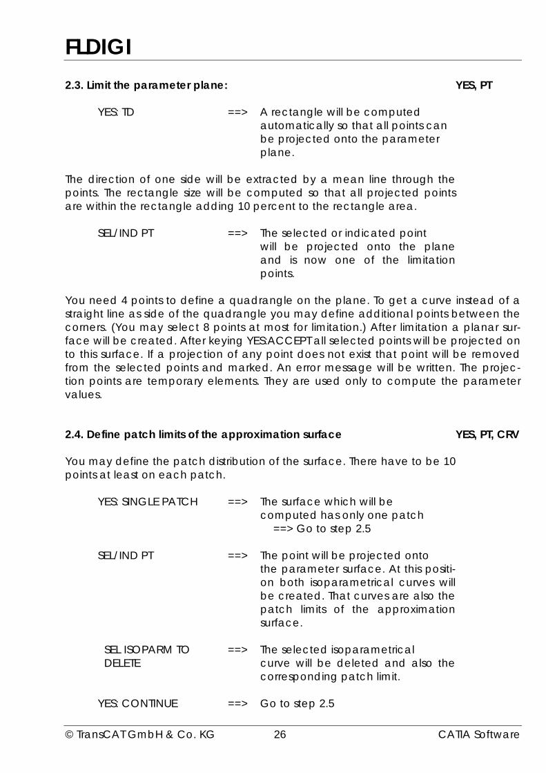
2.3. Limit the parameter plane: YES, PT
YES: TD ==> A rectangle will be computedautomatically so that all points canbe projected onto the parameterplane.
The direction of one side will be extracted by a mean line through thepoints. The rectangle size will be computed so that all projected pointsare within the rectangle adding 10 percent to the rectangle area.
SEL/IND PT ==> The selected or indicated pointwill be projected onto the planeand is now one of the limitationpoints.
You need 4 points to define a quadrangle on the plane. To get a curve instead of astraight line as side of the quadrangle you may define additional points between thecorners. (You may select 8 points at most for limitation.) After limitation a planar sur-face will be created. After keying YES:ACCEPT all selected points will be projected onto this surface. If a projection of any point does not exist that point will be removedfrom the selected points and marked. An error message will be written. The projec-tion points are temporary elements. They are used only to compute the parametervalues.
2.4. Define patch limits of the approximation surface YES, PT, CRV
You may define the patch distribution of the surface. There have to be 10points at least on each patch.
YES: SINGLE PATCH ==> The surface which will becomputed has only one patch
==> Go to step 2.5
SEL/IND PT ==> The point will be projected ontothe parameter surface. At this positi-on both isoparametrical curves willbe created. That curves are also thepatch limits of the approximationsurface.
SEL ISOPARM TO ==> The selected isoparametricalDELETE curve will be deleted and also the
corresponding patch limit.
YES: CONTINUE ==> Go to step 2.5
FLDIGI
© TransCAT GmbH & Co. KG 27 CATIA Software
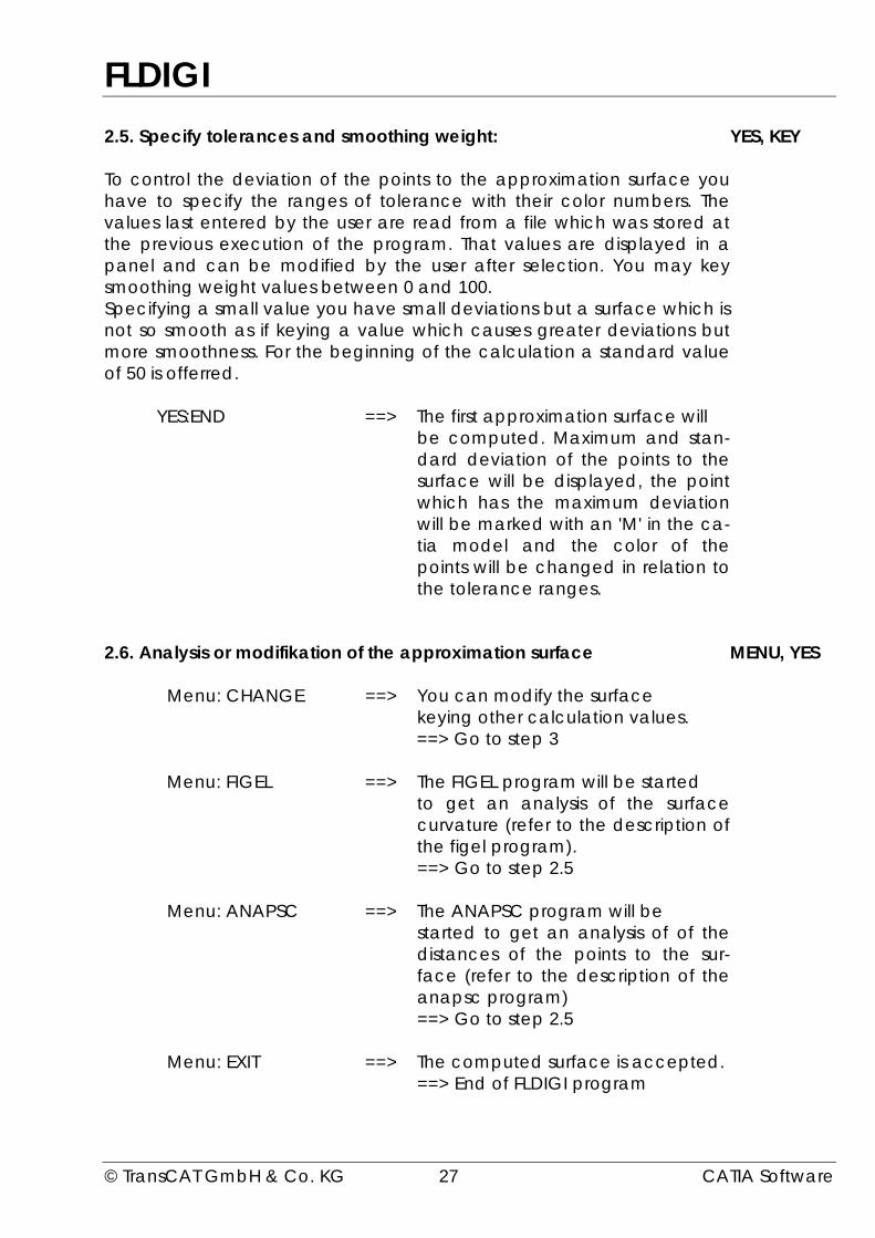
2.5. Specify tolerances and smoothing weight: YES, KEY
To control the deviation of the points to the approximation surface youhave to specify the ranges of tolerance with their color numbers. Thevalues last entered by the user are read from a file which was stored atthe previous execution of the program. That values are displayed in apanel and can be modified by the user after selection. You may keysmoothing weight values between 0 and 100.Specifying a small value you have small deviations but a surface which isnot so smooth as if keying a value which causes greater deviations butmore smoothness. For the beginning of the calculation a standard valueof 50 is offerred.
YES:END ==> The first approximation surface willbe computed. Maximum and stan-dard deviation of the points to thesurface will be displayed, the pointwhich has the maximum deviationwill be marked with an 'M' in the ca-tia model and the color of thepoints will be changed in relation tothe tolerance ranges.
2.6. Analysis or modifikation of the approximation surface MENU, YES
Menu: CHANGE ==> You can modify the surfacekeying other calculation values.==> Go to step 3
Menu: FIGEL ==> The FIGEL program will be startedto get an analysis of the surfacecurvature (refer to the description ofthe figel program).==> Go to step 2.5
Menu: ANAPSC ==> The ANAPSC program will bestarted to get an analysis of of thedistances of the points to the sur-face (refer to the description of theanapsc program)==> Go to step 2.5
Menu: EXIT ==> The computed surface is accepted.==> End of FLDIGI program
FLDIGI
© TransCAT GmbH & Co. KG 28 CATIA Software
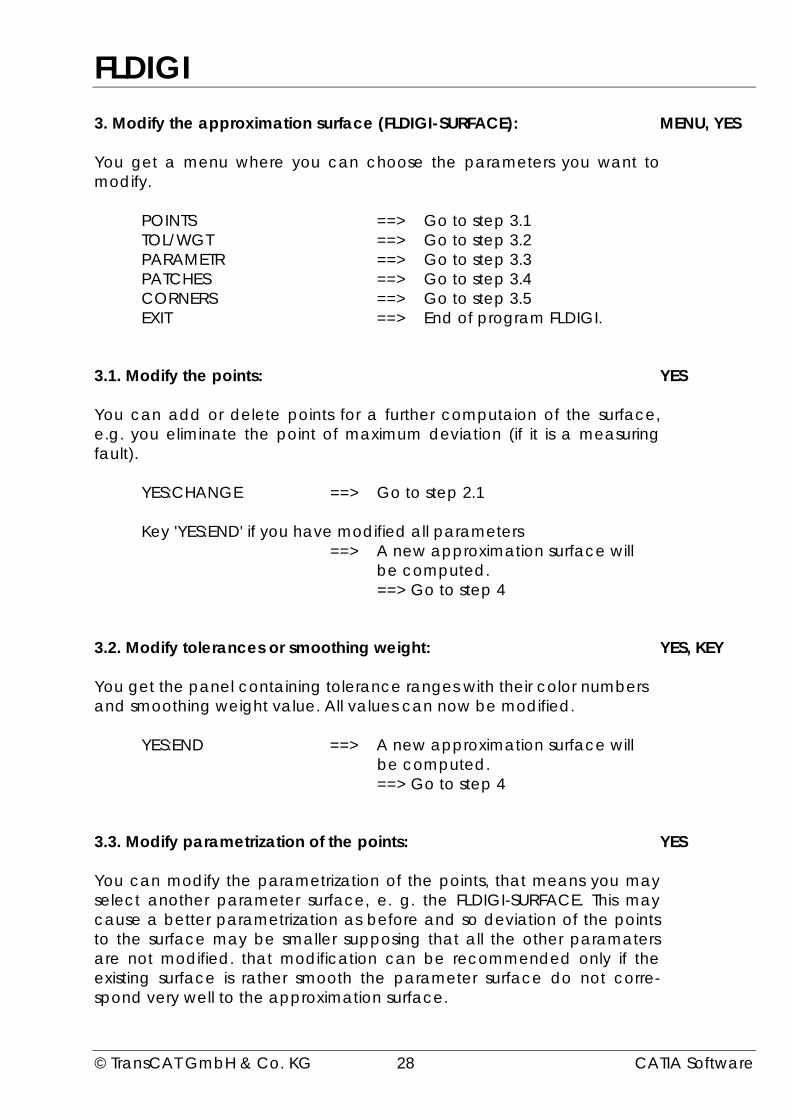
3. Modify the approximation surface (FLDIGI-SURFACE): MENU, YES
You get a menu where you can choose the parameters you want tomodify.
POINTS ==> Go to step 3.1TOL/WGT ==> Go to step 3.2PARAMETR ==> Go to step 3.3PATCHES ==> Go to step 3.4CORNERS ==> Go to step 3.5EXIT ==> End of program FLDIGI.
3.1. Modify the points: YES
You can add or delete points for a further computaion of the surface,e.g. you eliminate the point of maximum deviation (if it is a measuringfault).
YES:CHANGE ==> Go to step 2.1
Key 'YES:END' if you have modified all parameters==> A new approximation surface will
be computed.==> Go to step 4
3.2. Modify tolerances or smoothing weight: YES, KEY
You get the panel containing tolerance ranges with their color numbersand smoothing weight value. All values can now be modified.
YES:END ==> A new approximation surface willbe computed.==> Go to step 4
3.3. Modify parametrization of the points: YES
You can modify the parametrization of the points, that means you mayselect another parameter surface, e. g. the FLDIGI-SURFACE. This maycause a better parametrization as before and so deviation of the pointsto the surface may be smaller supposing that all the other paramatersare not modified. that modification can be recommended only if theexisting surface is rather smooth the parameter surface do not corre-spond very well to the approximation surface.
FLDIGI
© TransCAT GmbH & Co. KG 29 CATIA Software
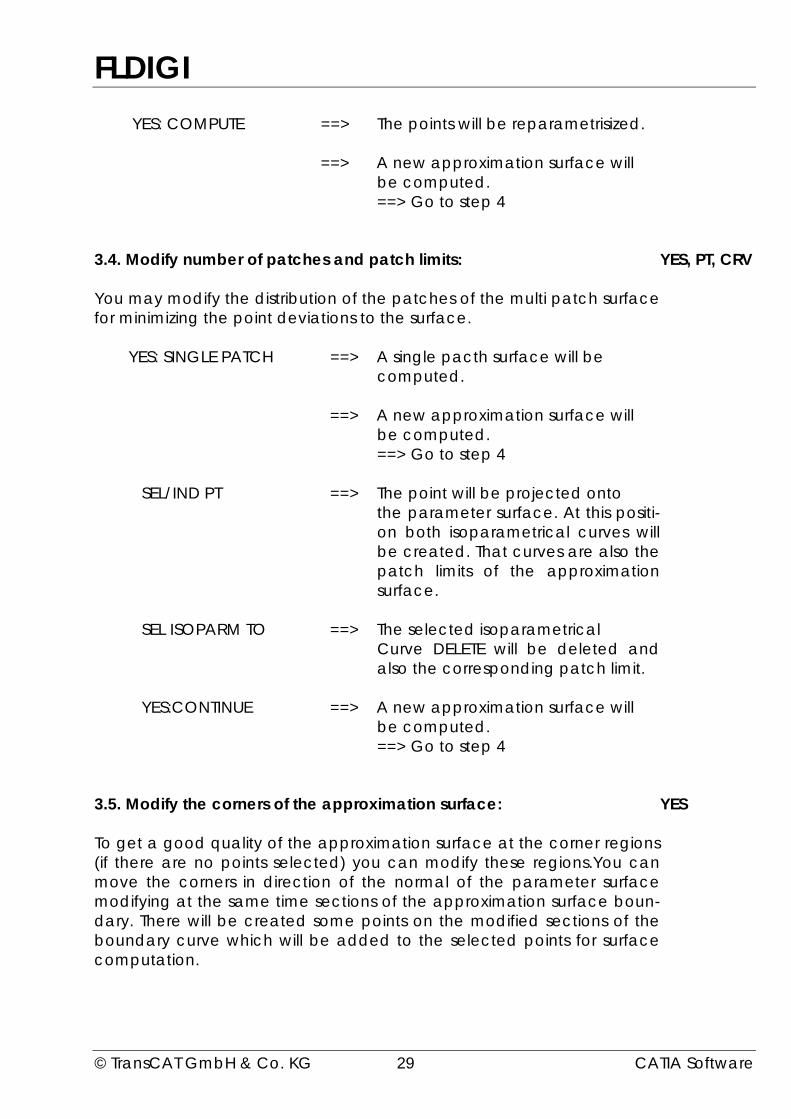
YES: COMPUTE ==> The points will be reparametrisized.
==> A new approximation surface willbe computed.==> Go to step 4
3.4. Modify number of patches and patch limits: YES, PT, CRV
You may modify the distribution of the patches of the multi patch surfacefor minimizing the point deviations to the surface.
YES: SINGLE PATCH ==> A single pacth surface will becomputed.
==> A new approximation surface willbe computed.==> Go to step 4
SEL/IND PT ==> The point will be projected ontothe parameter surface. At this positi-on both isoparametrical curves willbe created. That curves are also thepatch limits of the approximationsurface.
SEL ISOPARM TO ==> The selected isoparametricalCurve DELETE will be deleted andalso the corresponding patch limit.
YES:CONTINUE ==> A new approximation surface willbe computed.==> Go to step 4
3.5. Modify the corners of the approximation surface: YES
To get a good quality of the approximation surface at the corner regions(if there are no points selected) you can modify these regions.You canmove the corners in direction of the normal of the parameter surfacemodifying at the same time sections of the approximation surface boun-dary. There will be created some points on the modified sections of theboundary curve which will be added to the selected points for surfacecomputation.

FLDIGI
© TransCAT GmbH & Co. KG 30 CATIA Software
3.5.1. Select the corner you want to modify: PT
Selection a point at one corner of the fldigi-surface you choose the cor-ner you want to modify.
3.5.2. Define the region of the surface you want to modify: PT
Indicating a point on the fldigi-surface you define the region of the sur-face you want to modify. Starting at the indicated point there will becreated isoparametrical curves in direction to the boundary curveswhich are joint with the selected corner. New boundary curves will alsocreated and limitated at the isoparametricals.
3.5.3. Move the corner along the normal vector KEY, YES
At the corner you want to modify there is displayed a normal vector ofthe parameter surface. You can move the corner along that normalspecifying a value in mm. Accordingly the boundary curves also will bemodified beeing tangent continuous to the approximation surface.
YES:END ==> Go to step 3.5.4
3.5.4. Key number of points per boundary KEY
To modify the corner some more points will be added for surface com-putation. You can specify the number of points on the modified boun-dary curves. These points will be created on the boundaries and toge-ther with the modified point of the corner added to the points to com-pute the approximation surface.
3.5.5. Confirm to create the new surface YES
After the points have been modified a new approximation surface willbe computed. The created points at the corner will be marked particu-larly that in case of modififying the same corner once more the pre-viously created points can be deleted.
==> Go to step 4

FLDIGI
© TransCAT GmbH & Co. KG 31 CATIA Software
4. Analysis or modification of the approximation surface MENU, YES
After modification of a previously computed surface (step 3) there areexisting two surfaces in catia model. Maximum and standard deviationof both surfaces are displayed, the point of the maximum deviation ofthe last created surface is marked by an 'M' and the points are displayedwith the color corresponding to the tolerance ranges.
It exists a menu in which you may select the following items:
CHANGE:
NEW SUR ==> Continue with modifying the lastcreated surface.
==> The previously created surfacewill be deleted.==> Go to step 3
OLD SUR ==> Continue with modifying thepreviously created surface.
==> The last created surface will bedeleted.
==> The points will be marked relativeto the previously created surface.==> Go to step 3
END:
NEW SUR ==> The previously created surfacewill be deleted.
==> The last created surface will bestored into the model and the pro-gram ends.
OLD SUR ==> The last created surface will bedeleted.
==> The points will be marked relativeto the previously created surface.
==> The previously created surfacewill be stored into the model andthe program ends.
FLDIGI
© TransCAT GmbH & Co. KG 32 CATIA Software
ANALYSIS:
FIGEL ==> The FIGEL program will be started toget an analysis of the surface curva-ture. (Refer to the description of theFIGEL program.)==> Go to step 4.
ANAPSC ==> The ANAPSC program will be startedto get an exact analysis of the pointdistances to the approximation sur-face. (Refer to the description of theANAPSC program.)==> Go to step 4.

FLUNT
© TransCAT GmbH & Co. KG 33 CATIA Software
Function FLUNT
With the FLUNT program it is possible to judge the quality of surfaces.
With this program you check roughly all surfaces of a catia model before you checksome single surfaces by other procedures. You may choose if you want to changecolor or layer of all detected surfaces. Then you may check and modify that surfacesby using other programs as ANAPSC, FIGEL, TANGO or TANGOMPS.
The following attributes of surfaces will be analysed:
- IP: the variation of curvature (inflection points)
==> the surface will be marked if there is both aconcave and a convex curvature.
- NV: possible sources of error at any position of the surfaces(undefined normal vectors)
==> the surface will be marked if both tangents at anyposition (u and v) are parallel or one of them has alength of zero.
- TS: deviations of points, normals, parameters andisoparametricals on the surface (at the patch limits)
==> the surface will be marked if there is
Point deviation Identical point toleranceParameter deviation Identical point toleranceNormal deviation 0.229 degreeIsoparametrical deviation 0.229 degree.
The FLUNT program was developed by STZ-RIM for the company Hella KG Hueck &Co.
FLUNT
© TransCAT GmbH & Co. KG 34 CATIA Software
Use of the program
What you have to do: Input:
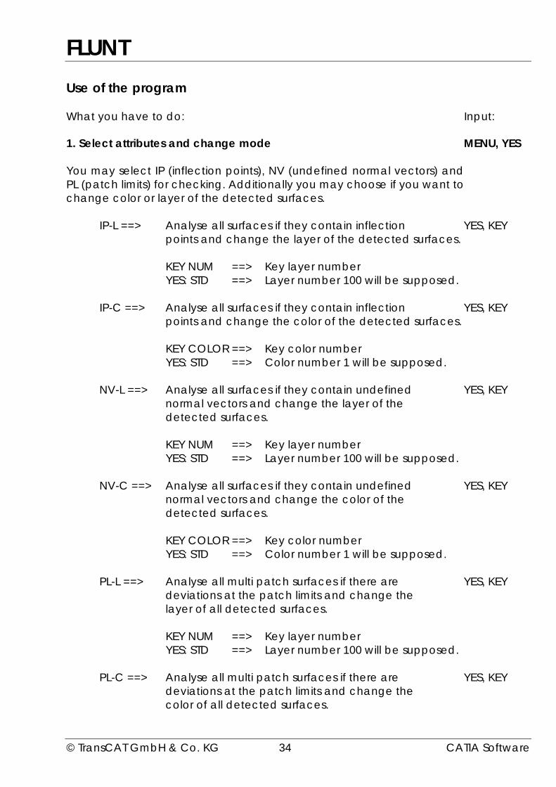
1. Select attributes and change mode MENU, YES
You may select IP (inflection points), NV (undefined normal vectors) andPL (patch limits) for checking. Additionally you may choose if you want tochange color or layer of the detected surfaces.
IP-L ==> Analyse all surfaces if they contain inflection YES, KEYpoints and change the layer of the detected surfaces.
KEY NUM ==> Key layer numberYES: STD ==> Layer number 100 will be supposed.
IP-C ==> Analyse all surfaces if they contain inflection YES, KEYpoints and change the color of the detected surfaces.
KEY COLOR ==> Key color numberYES: STD ==> Color number 1 will be supposed.
NV-L ==> Analyse all surfaces if they contain undefined YES, KEYnormal vectors and change the layer of thedetected surfaces.
KEY NUM ==> Key layer numberYES: STD ==> Layer number 100 will be supposed.
NV-C ==> Analyse all surfaces if they contain undefined YES, KEYnormal vectors and change the color of thedetected surfaces.
KEY COLOR ==> Key color numberYES: STD ==> Color number 1 will be supposed.
PL-L ==> Analyse all multi patch surfaces if there are YES, KEYdeviations at the patch limits and change thelayer of all detected surfaces.
KEY NUM ==> Key layer numberYES: STD ==> Layer number 100 will be supposed.
PL-C ==> Analyse all multi patch surfaces if there are YES, KEYdeviations at the patch limits and change thecolor of all detected surfaces.

FLUNT
© TransCAT GmbH & Co. KG 35 CATIA Software
KEY COLOR ==> Key color numberYES: STD ==> Color number 1 will be supposed.
COMPUTE ==> Go to step 2YES ==> Go to step 2
You may do only one selection for IP, NV and PL, so for example it is notpossible to select IP-L and IP-C for one program execution.
2. Start surface analysis? YES
YES: ACCEPT ==> The program will be started corresponding to the selections you havedone.
3. Restart analysis? YES, MENU
YES: AGAIN ==> Go to step 1

ISOLATE
© TransCAT GmbH & Co. KG 36 CATIA Software
Function ISOLATE
Erase of logical links between curves and surfaces by MULTI-SELECT.
If there are curves with strong-links which can't be erased, e.g. because of usingwithin a nc-definition, the curves will be duplicated. The duplicated curves have nolinks to the other elements.
The ISOLATE program was developed by STZ-RIM for the company Hella KG Hueck &Co.
Use of the program
What you have to do: Input:
1. select the curves to be isolated: CCV, KEYYES
The curves (*LN, *CRV or *CCV), whose logical links to survaces (*SUR or*FAC) should be erased, may be selected or determined by multi-select.
YES: COMPUTE ==> Erase of logical links
2. more links to erase: YES, MENU
YES: AGAIN ==> Go to step 1.
TANGO
© TransCAT GmbH & Co. KG 37 CATIA Software
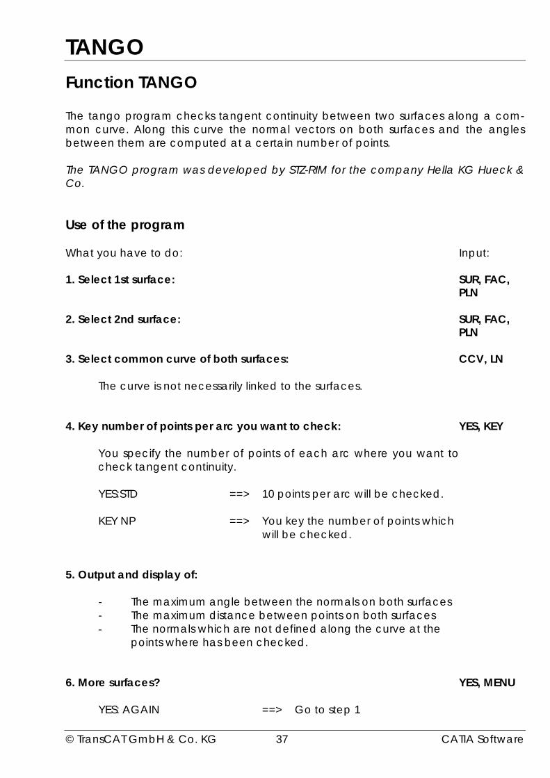
Function TANGO
The tango program checks tangent continuity between two surfaces along a com-mon curve. Along this curve the normal vectors on both surfaces and the anglesbetween them are computed at a certain number of points.
The TANGO program was developed by STZ-RIM for the company Hella KG Hueck &Co.
Use of the program
What you have to do: Input:
1. Select 1st surface: SUR, FAC,PLN
2. Select 2nd surface: SUR, FAC,PLN
3. Select common curve of both surfaces: CCV, LN
The curve is not necessarily linked to the surfaces.
4. Key number of points per arc you want to check: YES, KEY
You specify the number of points of each arc where you want tocheck tangent continuity.
YES:STD ==> 10 points per arc will be checked.
KEY NP ==> You key the number of points whichwill be checked.
5. Output and display of:
- The maximum angle between the normals on both surfaces- The maximum distance between points on both surfaces- The normals which are not defined along the curve at the
points where has been checked.
6. More surfaces? YES, MENU
YES: AGAIN ==> Go to step 1
TANGOMAC
© TransCAT GmbH & Co. KG 38 CATIA Software
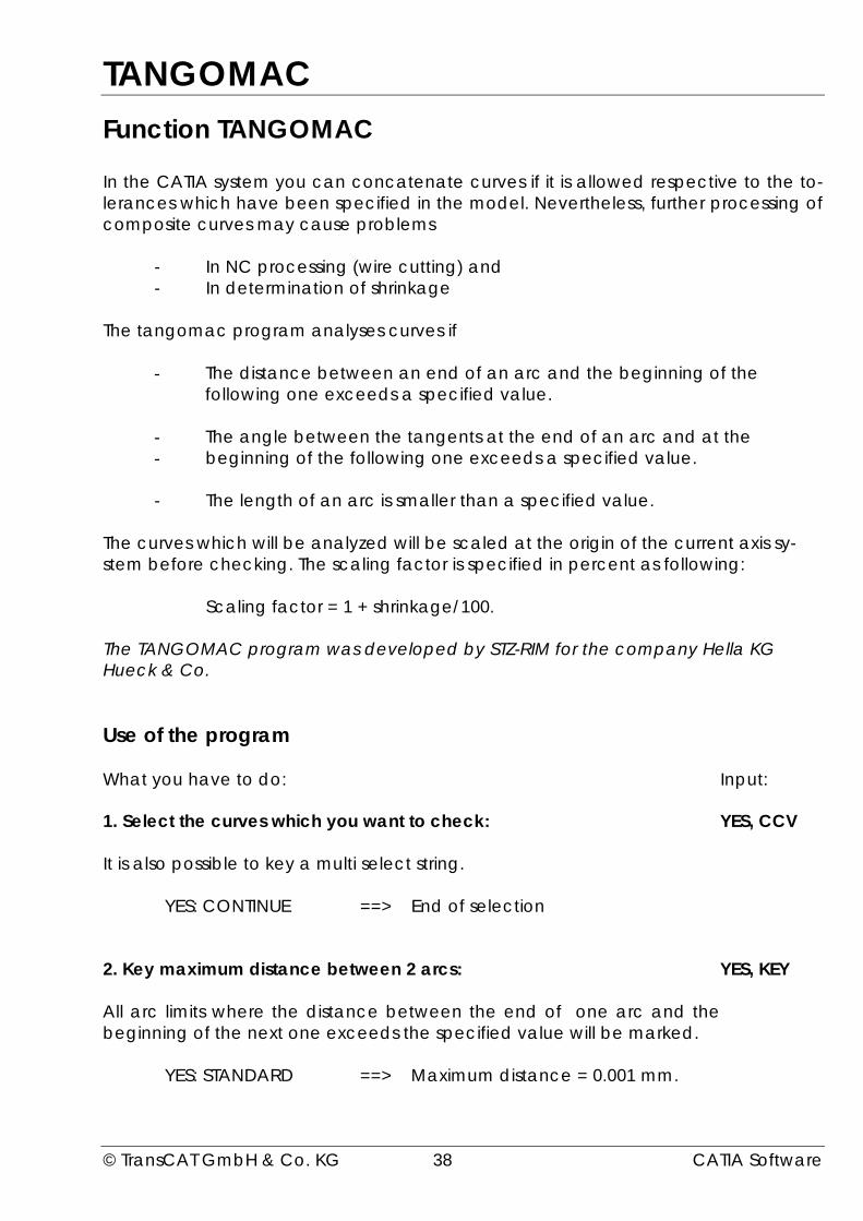
Function TANGOMAC
In the CATIA system you can concatenate curves if it is allowed respective to the to-lerances which have been specified in the model. Nevertheless, further processing ofcomposite curves may cause problems
- In NC processing (wire cutting) and- In determination of shrinkage
The tangomac program analyses curves if
- The distance between an end of an arc and the beginning of thefollowing one exceeds a specified value.
- The angle between the tangents at the end of an arc and at the- beginning of the following one exceeds a specified value.
- The length of an arc is smaller than a specified value.
The curves which will be analyzed will be scaled at the origin of the current axis sy-stem before checking. The scaling factor is specified in percent as following:
Scaling factor = 1 + shrinkage/100.
The TANGOMAC program was developed by STZ-RIM for the company Hella KGHueck & Co.
Use of the program
What you have to do: Input:
1. Select the curves which you want to check: YES, CCV
It is also possible to key a multi select string.
YES: CONTINUE ==> End of selection
2. Key maximum distance between 2 arcs: YES, KEY
All arc limits where the distance between the end of one arc and thebeginning of the next one exceeds the specified value will be marked.
YES: STANDARD ==> Maximum distance = 0.001 mm.
TANGOMAC
© TransCAT GmbH & Co. KG 39 CATIA Software
3. Key maximum angle of tangents between 2 arcs: YES, KEY
All arc limits where the angle between the tangent at the end of one arcand the tangent at the beginning of the next one exceeds the specifiedvalue will be marked.
YES: STANDARD ==> Maximum tangent angle = 0.2 degree
4. Key minimum arc length: YES, KEY
All arcs of which the length is smaller than the specified value will bemarked.
YES:STANDARD ==> Minimum arc length = 0.05 mm.
5. Key shrinkage in percent: YES, KEY
With the shrinkage value the scaling of the curves will be calculated atthe origin of the current axis system by the expression:
Scaling factor = 1 + Shrinkage/100.
YES: STANDARD ==> Shrinkage = 0.5 percent
6. Confirm all specified values: YES
YES: ACCEPT ==> Start of analysis.
7. Output of the computed values: YES, MENU
The maximum distance, the maximum angle between the tangents atthe arc limits and the minumum arc length are displayed.
YES: AGAIN ==> Go to step 1
TANGOMPS
© TransCAT GmbH & Co. KG 40 CATIA Software
Function TANGOMPS
The TANGOMPS program checks the deviations of
- Points - Normals- Parameters - Isoparametricals
along the patch limits of a multi patch surface.
The TANGOMPS program was developed by STZ-RIM for the company Hella KGHueck & Co.
Use of the program
What you have to do: Input:
1. Select the surface which you want to check: SUR
2. Key tolerance of angle between the normals: YES, KEY
All patch limits where the angle deviations of normals or isoparametricalsis greater than the value you have keyed will be indicated. The toleran-ce value must be specified in degree.
YES: STD ==> Standard tolerance of 0.2 degreewill be supposed.
KEY TOL ==> You key an angle for tolerance.
3. Key tolerance of points: YES, KEY
All patch limits where the deviations of points or parameters are greaterthan the value you have keyed will be indicated. The tolerance valuemust be specified in mm.
YES: STD ==> Identical curve tolerance will besupposed.
KEY TOL ==> You key a tolerance value in mm.

TANGOMPS
© TransCAT GmbH & Co. KG 41 CATIA Software
4. Key number of points per patch limit for checking: YES, KEY
The deviations along the patch limits will be checked at the specifiednumber of equidistant points.
YES: STD ==> 10 points per patch limit will be supposed.
KEY TOL ==> You specify the number of pointsby keyboard.
5. Output and display: YES
In the message area will be displayed
- Maximum deviation of normals- Maximum deviation of points
between two patches.
All patch limits where are deviations which are greater than the specifiedtolerances will be indicated; texts which show the deviations will be dis-played.
YES: CONTINUE ==> Go to step 6
6. More multi patch surfaces? YES, MENU
YES: AGAIN ==> Go to step 1
WKZT1
© TransCAT GmbH & Co. KG 42 CATIA Software
Function WKZT1
With the WKZT1 program you can create mould seam surfaces along a mould seamcurve as input.
The linear direction of the mould seam surface along the mould seam curve is de-fined by:
- One direction (line) or
- Two directions at both end points of the mould seam curve(averaging of both directions along the curve) or
- A plane (linear direction parallel to the plane and orthogonalto the mould seam curve)
The WKZT1 program was developed by stz-rim for the company Hella KG Hueck &Co.
Use of the program
What you have to do: Input:
1. Select mould seam curve: CCV, LN
2. Specify 1st direction of mould seam surface: PT, LN, PLNMENU
The direction of the extension of the mould seam surface at the begin-ning point of the mould seam curve can be specified by
SEL PT1 ==> SEL PT2 (direction will be definedby 2 points)
SEL LN ==> Direction will be defined byselecting a line
SEL PLN ==> Direction is parallel to the selectedplane along the mould seam curve
Menu:X-AXIS ==> Direction is the current x-axisMenu:Y-AXIS ==> Direction is the current y-axisMenu:Z-AXIS ==> Direction is the current z-axis
WKZT1
© TransCAT GmbH & Co. KG 43 CATIA Software
3. Invert 1st direction: YES, ARW
A vector which shows the direction of extension is displayed at the be-ginning point of the mould seam curve.
SEL ARW TO INV ==> Vector will be inverted
YES:CONTINUE ==> If you didn't select a plane in step 2go to step 5
4. Create tangent continuous mould seam surface? YES, MENU
If the mould seam curve is not curvature continuous it is impossible tocreate an exact tangent continuous surface parallel to the selectedplane along the curve.
You have 2 possibilities:
- Create an exact surface:Maybe that parts of the surface will not be tangentcontinuous or
- Create a tangent continuous surface:The linear direction of the surface has not necessarilyan orthogonal angle to the mould seam curve.
YES: TGT-CONT ==> Create a tangent continuoussurface.
Menu: EXACT ==> Create an exact surface.Go to step 7
5. Specify 2nd direction of mould seam surface: YES, PT, LNMENU
The direction of the extension of the mould seam surface at the endpoint of the mould seam curve can be specified by
YES: SAME ==> Same direction as at the beginningpoint
SEL PT1 ==> SEL PT2 (direction will be defined by2 points)

WKZT1
© TransCAT GmbH & Co. KG 44 CATIA Software
SEL LN ==> Direction will be defined byselecting a line
Menu:X-AXIS ==> Direction is the current x-axis
Menu:Y-AXIS ==> Direction is the current y-axis
Menu:Z-AXIS ==> Direction is the current z-axis
6. Invert 2nd direction: YES, ARW
A vector which shows the direction of extension is displayed at the endpoint of the mould seam curve.
SEL ARW TO INV ==> Vector will be inverted.
YES: CONTINUE ==> Go to step 7
7. Key width of mould seam surface: YES, KEY
You have to specify the width of the mould seam surface in mm.
YES: STD ==> Standard width will be supposed(30.00 mm).
KEY WIDTH ==> Key value of width by keyboard.
8. Confirm input parameters: YES
You have to confirm all the input parameters before the computationprogram starts. By keying 'no' you return to step 6.
YES: ACCEPT ==> Start of computation.
9. More type 1 mould seam surfaces? YES, MENU
YES: AGAIN ==> Go to step 1

WKZT2
© TransCAT GmbH & Co. KG 45 CATIA Software
Function WKZT2
With the WKZT2 program you can create mould seam surfaces along a mould seamcurve as input.
The linear direction of the mould seam surface along the mould seam curve is de-fined by:
- A surface (the mould seam surface is tangent continuous to the surface along the mould seam curve) or
- A curve (the curve is on the extrapolated mould seam surface).
The WKZT2 program was developed by STZ-RIM for the company Hella KG Hueck &Co.
Use of the program
What you have to do: Input:
1. Select mould seam curve: CCV
2. Specify direction of mould seam surface: CCV,SUR,FAC
The direction of the extension of the mould seam surface can bespecified by
SEL CCV ==> The selected curve will define thedirection of the mould seam sur-face, that means the curve is on theextrapolated surface.==> go to step 3
SEL SUR/FAC ==> The mould seam surface which willbe created is tangent continuous tothe selected surface.==> go to step 4
WKZT2
© TransCAT GmbH & Co. KG 46 CATIA Software
3. Invert direction of the direction curve? YES, ARW
A vector which shows the direction of the curve is displayed at the be-ginning point of the selected curve.
YES: CONTINUE ==> Go to step 4
SEL ARW TO INV ==> Vector will be inverted.
4. Invert extension direction of mould seam surface? YES, ARW
A vector which shows the direction of extension is displayed at the be-ginning point of the mould seam curve.
YES: CONTINUE ==> Go to step 5
SEL ARW TO INV ==> Vector will be inverted.
5. Key width of mould seam surface: YES, KEY
You have to specify the width of the mould seam surface in mm.
YES: STD ==> Standard width will be supposed(30.00 mm).
KEY WIDTH ==> Key value of width by keyboard.
6. Confirm input parameters: YES
You have to confirm all the input paramters before the computationprogram starts. By keying 'no' you return to step 5.
YES: ACCEPT ==> Start of computation.
7. More type 2 mould seam surfaces? YES, MENU
YES: AGAIN ==> Go to step 1

WKZT3
© TransCAT GmbH & Co. KG 47 CATIA Software
Function WKZT3
With the wkzt3 program you can create mould seam surfaces along a mould seamcurve as input.
It will be created a mould seam surface which connects two already existing mouldseam surfaces and is tangent continuous to them. In this case the mould seam curvecan be reduced to a point (triangular surface).
The WKZT3 program was developed by STZ-RIM for the company Hella KG Hueck &Co.
Use of the program
What you have to do: Input:
1. Select mould seam curve: CCV,LN,PT
You may select a curve, line or a point.
2. Select 1st surface for tangent direction SUR
The selected surface will be limit the mould seam surface and will betangent continuous to it.
Requirements to the surface:
- In one direction (u or v) only one patch.
- In one direction (u or v) of degree 1.
- A corner of the surface has the same coordinates as oneend point of the mould seam curve.
- At that end point the tangent of the mould seam curve isidentical to one tangent of the surface.
WKZT3
© TransCAT GmbH & Co. KG 48 CATIA Software
3. Limitation of the 1st surface: YES, PT, KEY
The limitation of the 1st surface will be an isoparametrical line of the sur-face. Along that isoparametrical the surface which will be created willbe tangent continuously connected.
The isoparametrical will be defined by:
IND/SEL PT ==> The selected point will be projectedto the surface. There will be createdthe linear isoparametrical. (Themould seam curve will be extendedup to the isoparametrical.)
KEY DIST ==> The keyed value is the distance onthe boundary of the selected sur-face which is tangent continuous tothe mould seam curve. There will becreated the linear isoparametrical.(The mould seam curve will be ex-tended up to the isoparametrical.)
YES:BOUNDARY ==> The boundary curve of the selectedsurface is used which is orthogonalto the mould seam curve.
4. Select 2nd surface for tangent direction SUR
The selected surface will be limit the mould seam surface and will betangent continuous to it. (There are the same requirements to the surfaceas in step 2.)
5. Limitation of the 2nd surface: YES, PT, KEY
The limitation of the 2nd surface will be an isoparametrical line of thesurface. Along that isoparametrical the surface which will be created willbe tangent continuously connected. (The specification of the isopara-metrical is identical to step 3.)
WKZT3
© TransCAT GmbH & Co. KG 49 CATIA Software
6. Modify tangents: YES, ARW,LN, KEY
Parallel to the mould seam curve another curve with its tangents will bedisplayed. That curve will be a boundary of the mould seam surfacewhich will be created. Any tangent (vector) is the active one und maybe modified.By modifying the tangent the curve and the mould seam surface also willbe modified.
SEL ARW ==> The selected tangent will be theactive one.
SEL LN ==> The active tangent will be orientedwith the selected line which is pro-jected onto the tangential plane.
KEY TL ==> The length of the active tangent willbe modified with the keyed lengthvalue.
YES: CONTINUE ==> Go to step 7
7. Confirm input parameters: YES
You have to confirm all the input parameters before the computationprogram starts. By keying 'no' youreturn to step 6.
YES: ACCEPT ==> Start of computation
8. Concatenate mould seam surfaces? YES, MENU
The select mould seam surfaces and the created one can be conca-tenated to one surface.
Menu: CONCATE ==> The surfaces will be concatenated.
YES: CONTINUE ==> Go to step 9
9. More type 3 mould seam surfaces? YES, MENU
YES: AGAIN ==> Go to step 1