Embed Size (px)
Citation preview
CATHODIC PROTECTION MONITORING VIA IN-LINE INSPECTION
By, P K Scott, Baker Hughes PMG, Houston, USA & M W Mateer, Shell Global Solutions, Houston, USA
ABSTRACT
Identifying problems with and monitoring the effectiveness of a pipeline’s cathodic protection (CP) system can be difficult, expensive and time consuming - especially when the pipe is located in an area of difficult access. If the CP could be monitored via an in-line inspection tool (smart \pig), then the protection status could be confirmed or problems identified regardless of the pipeline location, accessibility, or condition of the ROW.
An in-line inspection tool capable of reading and recording the magnitude and polarity of current supplied by cathodic protection has been developed and tested in both crude oil and refined product pipelines. The results show that CP currents can be quickly, accurately and efficiently gathered without access to the outside surface of the pipe. For difficult to access areas, CPCMTM Cathodic Protection Current Measurement in-line inspection provides for a reliable, cost effective, time saving way to monitor, validate, or trouble shoot a pipeline’s cathodic protection system.
Keywords: CPCM, cathodic protection, cathodic protection current, current, pipeline, right of way, pigs, net current gain, current density , cp
INTRODUCTION
From the beginning of cathodic protection, it was understood that the flow of direct electrical current was the key to protecting a pipeline from corrosion. As A. W. Peabody wrote in his classic book, “Pipeline Corrosion Control”, the basic theory of cathodic protection involves the use of current to protect against corrosion. He wrote, “When the amount of current is adjusted properly, there will be a net current flow onto the pipe surface (at all points). The entire surface then will be cathodic and the protection complete.” 1
Corrosion professionals have long valued the concept of a pig that could measure CP current in the pipe and several attempts were made to develop a device similar to down hole wire line tools that measure current in well casings.2 However, practical and technical issues proved too difficult to solve with existing technology and those attempts were abandoned.
Development of CP practice centered around the measurement of the pipe-to-soil potential produced by the CP current because they were measurable, at least in theory, over the entire pipe surface using available technology. This state of affairs lasted until recently when a joint project between Shell Global Solutions, Baker-Hughes Pipeline Management and the United States Department of Transportation (DOT) overcame these challenges with the development of the Cathodic Protection Current Measurement (CPCM) in-line inspection tool. With this tool, the practical collection of accurate CP current information is available over an entire pipeline segment for the first time.
The CPCM cathodic protection current measurement in-line inspection tool provides two advantages to the pipeline operator:
1. It measures CP current direction and magnitude in the pipeline to supplement and extend the pipe-to-soil potential data already available, and;
2. It allows the pipeline operator to easily gather CP information regardless of right-of-way obstacles or obstructions, IR drop issues or stray current interference.
Copyright © 2007, Pigging Products and Services Association.
While interpretation of CPCM data continues to be refined, work to date has shown that the tool generates much useful and accurate information – information that is unobtainable from a potential survey. The tools can quickly and accurately determine current density applied continuously along the pipeline as well as the location and magnitude of current leaving (rectifiers, bonds, anodes) or entering (bonds, shorts) by metallic connections.
THE VALUE OF CURRENT MEASUREMENT
During cathodic protection, steel is polarized by the effect of a flow of direct current, reducing the anodic area of the surface where corrosion occurs. If the current flow and polarization is great enough, the current will enter the steel at all points, eliminating all local anodes and preventing corrosion. The relationship between current, potential and resistance is represented by the well-known equation E = IR. From this relationship, it is easy to illustrate that polarization and current density provide essentially equal information. Knowing the value of one and the specific coating resistance at any point, it is possible to calculate the other3.
Based on this information, the current survey provided by the CPCM tool provides the same amount and type of information as a close interval survey (CIS). The only advantage to the potential survey is that well-established potential criteria are available to determine protection, while current density criteria are not.
Development of suitable current density criteria to prove protection would certainly be beneficial and this project is currently planned. Used together, current and potential measurements would allow for a complete characterization of the CP system and a complete understanding of the performance of the coating system.
BENEFITS TO CATHODIC PROTECTION CURRENT MONITORING
While more work is needed to fully exploit all the capabilities of the inspection tool and the resulting measurements, monitoring CP current has a number of immediate practical advantages over external potential measurements:
• Right-of-way access issues are eliminated – Because the tool measures current from inside the pipe, access to the outside of the pipe is unnecessary. The pipeline can be surveyed regardless of right-of-way condition or location. There is no need to deal with landowners, hire crews or boats, submit permits or even know the exact pipeline location.
• Stray current interference is easily detected – Unlike potential data which requires interpretation to find the presence of stray current interference and can only guess at its magnitude or direction, current data clearly shows the exact location, magnitude and direction of unwanted current for external sources such as utilities, power lines, DC rail or other CP systems.
• IR drop is unimportant – IR voltage in the ground surrounding the pipe causes unwanted shifts in external potential measurements but has no impact on the current measurement. CPCM surveys do not require interruption of CP systems. In fact, rectifiers should be in normal operational mode for best results.
• Crowded right-of-ways are not problematic – The presence of other pipelines in close proximity in a single right-of-way has no impact on current measurements. Only the current on the pipeline being surveyed is measured, regardless of other pipelines nearby.
• Current data provides DCVG information in the same survey – Current density information duplicates the information produced by a DCVG survey, giving the effect of two surveys in a single inspection. (CIS and DCVG)
Page 2 of 7Copyright © 2007, Pigging Products and Services Association.
FIELD TRIALS
Field Trial #1
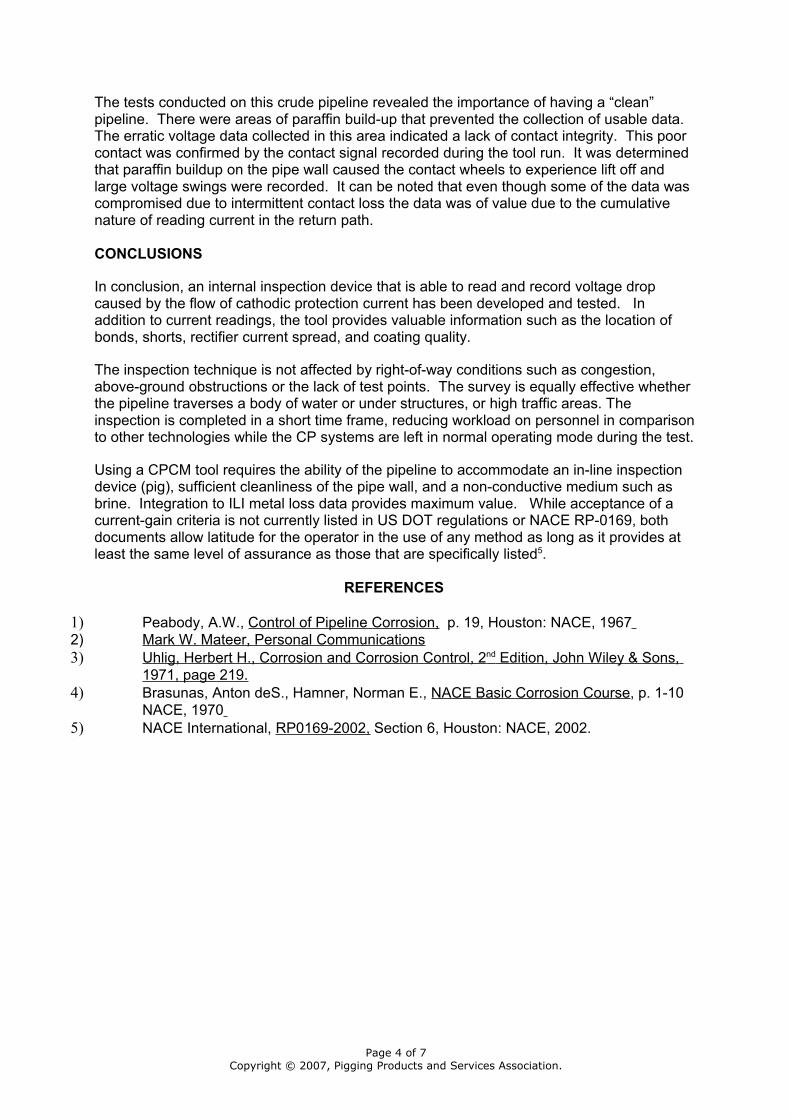
Field trials were performed in a 12.75” (324mm) 8 mile (12.9km) long refined products pipeline. This pipeline was selected due to size, length, proximity to the inspection operations base and access to previous MFL (smart pig) data. (Fig. 1)
A total of 5 Cathodic Protection Current Measurement test runs were performed on this pipeline. The first three runs were used to refine the tool configuration and design, and the last two runs tested the pipeline’s cathodic protection system; first in a test mode, then in “normal” mode. During the test mode the cathodic protection rectifier and bonds were synchronously interrupted and a sampling of the casings and pipeline crossings were bonded through an interrupter using discerning time schedules. An example of the data is shown in Fig. 2.
The pipeline offered a challenging test due to the physical characteristics and features of the pipeline. Most of the features were due to the pipeline age, service history and past repair methods. These features resulted in resistance changes to the pipe and consisted of numerous pipe changes and repair sleeves.
All of these features complicated the analysis but offered valuable information and experience in data interpretation. Knowledge and experience were gained with respect to the effect of the physical features including pipe types (i.e. seamless vs. bell & spigot) as well as wall thickness changes.
One notable observation was that shock to the contact wheels provides a repeatable signature that can be filtered or used for alignment. The ILI MFL data proved to be vital in this task and it became obvious that the integration of metal loss ILI and CP data adds incremental value in telling the complete story of the status of a pipeline (Fig. 3).
The CPCM tool trial runs revealed that the pipeline as originally tested was in need of additional CP current. The test run allowed analysts to quantify the amount of current that was being received from the foreign rectifiers at either end. The effects of adding a rectifier, coating damage and areas of large current drains from shorts were also apparent.
A rectifier and groundbed were installed prior to test runs #4 and #5. The additional current from the rectifier was captured during the last two test runs and highlighted an area of bare pipe that was not visible before the additional current was applied. (Fig. 4)
Field Trial #2
A 12 inch (324mm) crude oil pipeline experiencing sudden low potentials offered an opportunity for additional validation of the CPCM tool. The tool information gained from this run identified the location of a shorted pipeline causing low pipe-to-soil potentials. The short was subsequently removed and the pipe-to-soil potentials returned to their historical values (Fig 5).
The data revealed the total current being applied to the pipeline and the pattern of each current source. From this information one mislabeled rectifier negative was identified, an insulator at an underwater tie-in was verified and the amount of current from the delivering and receiving stations was discerned.
Page 3 of 7Copyright © 2007, Pigging Products and Services Association.
The tests conducted on this crude pipeline revealed the importance of having a “clean” pipeline. There were areas of paraffin build-up that prevented the collection of usable data. The erratic voltage data collected in this area indicated a lack of contact integrity. This poor contact was confirmed by the contact signal recorded during the tool run. It was determined that paraffin buildup on the pipe wall caused the contact wheels to experience lift off and large voltage swings were recorded. It can be noted that even though some of the data was compromised due to intermittent contact loss the data was of value due to the cumulative nature of reading current in the return path.
CONCLUSIONS
In conclusion, an internal inspection device that is able to read and record voltage drop caused by the flow of cathodic protection current has been developed and tested. In addition to current readings, the tool provides valuable information such as the location of bonds, shorts, rectifier current spread, and coating quality.
The inspection technique is not affected by right-of-way conditions such as congestion, above-ground obstructions or the lack of test points. The survey is equally effective whether the pipeline traverses a body of water or under structures, or high traffic areas. The inspection is completed in a short time frame, reducing workload on personnel in comparison to other technologies while the CP systems are left in normal operating mode during the test.
Using a CPCM tool requires the ability of the pipeline to accommodate an in-line inspection device (pig), sufficient cleanliness of the pipe wall, and a non-conductive medium such as brine. Integration to ILI metal loss data provides maximum value. While acceptance of a current-gain criteria is not currently listed in US DOT regulations or NACE RP-0169, both documents allow latitude for the operator in the use of any method as long as it provides at least the same level of assurance as those that are specifically listed5.
REFERENCES
1) Peabody, A.W., Control of Pipeline Corrosion, p. 19, Houston: NACE, 1967 2) Mark W. Mateer, Personal Communications 3) Uhlig, Herbert H., Corrosion and Corrosion Control, 2 nd Edition, John Wiley & Sons,
1971, page 219.4) Brasunas, Anton deS., Hamner, Norman E., NACE Basic Corrosion Course, p. 1-10
NACE, 1970 5) NACE International, RP0169-2002, Section 6, Houston: NACE, 2002.
Page 4 of 7Copyright © 2007, Pigging Products and Services Association.
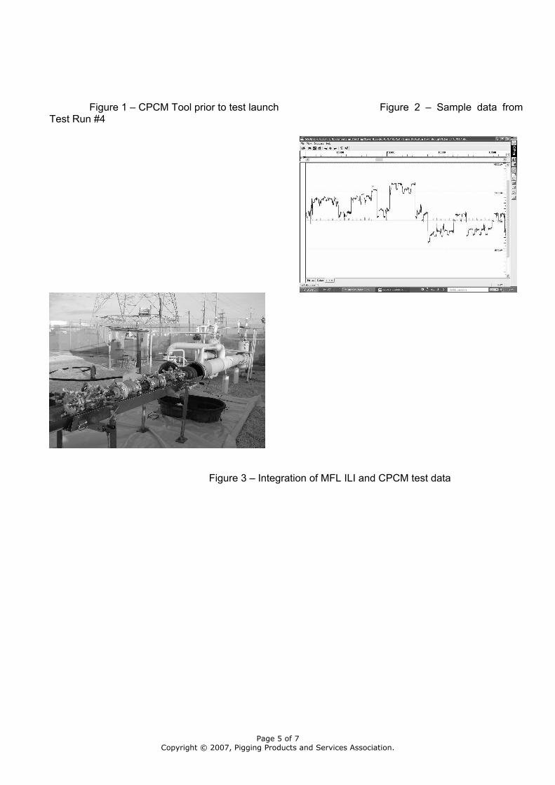
Figure 1 – CPCM Tool prior to test launch Figure 2 – Sample data from Test Run #4
Figure 3 – Integration of MFL ILI and CPCM test data
Page 5 of 7Copyright © 2007, Pigging Products and Services Association.
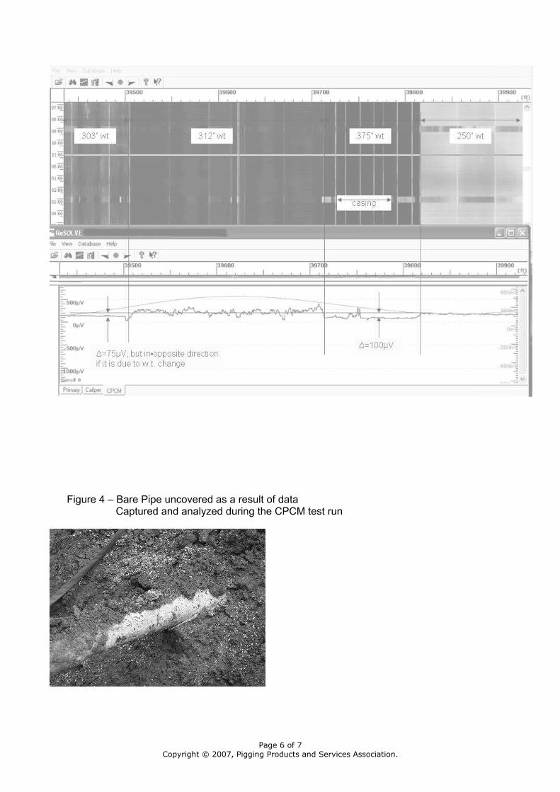
Figure 4 – Bare Pipe uncovered as a result of data Captured and analyzed during the CPCM test run
Page 6 of 7Copyright © 2007, Pigging Products and Services Association.

Figure 5- Pipe to soil potential before and after shorted pipe was removed
Page 7 of 7Copyright © 2007, Pigging Products and Services Association.