Embed Size (px)
Citation preview

Van der GraafPower Transmission Equipment
Product information
Drummotors
TM 100B25
w w w . v a n d e r g r a a f p t e . n l

The TM 100’s

playground

Copyright © 2010 Van der Graaf B.V.
All Rights Reserved. Modifi cations and errors excepted.
Van der Graaf has achieved
a prominent position on both
the domestic and international
market with its “GV” Drummotors.
The “GV” Drummotor has
found success in a wide range
of applications including the
following: automotive, X-ray,
construction, postal, courier,
mining, aggregate, airline
baggage, package fl ow, tyre
manufacturing, fi sh processing,
poultry processing, meat
processing, agriculture, fruit and
vegetable, farming, forestry,
baking, dairy and many more.
4
5
6
7
8
9
12
15
16
Introduction
Selection table
Dimensions Drummotor mild steel
Dimensions Taildrum mild steel
Dimensions Drummotor stainless steel
Dimensions Taildrum stainless steel
Dimensions bracket / Cable exit
Cross sectional / parts description
Options
Product range
Contact us
4 | TM 100B25
A wide range of applications
TM 100B25Introduction
5TM 100B25 |
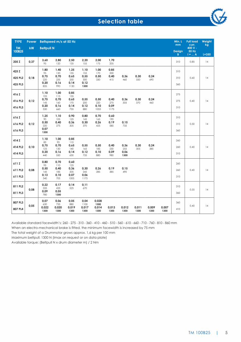
Selection table
TYPE
TM100B25
Power
kW
Beltspeed m/s at 50 Hz
Beltpull N
Min. Lmm
DesignB
Full loadcurr.
400 V -50 Hz
I = ... A
Weightkg
L=350
205 Z 0,37 3,6095
2,80120
2,50135
2,20155
2,00175
1,70205
310 0,85 14
425 Z
425 PL2
425 PL3
0,18
1,8095
0,752200,20835
1.401200,702350,16990
1,251350,652500,141130
1,101550,553000,121300
1,001700,50330
0,852000,40415
0,36460
0,30550
0,24690
310
310
360
0,60 14
416 Z
416 PL2
416 PL3
0,12
1,101050,751450,20530
1,001150,701600,16660
0,851350,651700,14755
0,552000,12880
0,502200,101055
0,402750,091175
0,36305
0,30370
0,24460
275
275
310
0,40 14
616 Z
616 PL2
616 PL3
0,12
1,2590
0,502200,071300
1,101050,40275
0,901250,36305
0,801450,30370
0,701650,26425
0,601900,19580
0,15735
310
310
360
0,50 14
414 Z
414 PL2
414 PL3
0,10
1,1085
0,751250,20440
1,0095
0,701300,16550
0,851100,651400,14630
0,551650,12735
0,501850,10880
0,402300,09980
0,362550,061300
0,30305
0,24385
260
260
310
0,40 14
611 Z
611 PL2
611 PL3
0,08
0,8095
0,501450,13540
0,701100,401850,10705
0,601250,362050,071005
0,302450,061175
0,26285
0,19385
0,15490
260
260
310
0,40 14
811 PL2
811 PL30,08
0,223350,09780
0,174350,051300
0,14525
0,11670
310
3600,55 14
807 PL3
807 PL40,05
0,07630
0,0221300
0,06735
0,0201300
0,05880
0,0191300
0,041100
0,0171300
0,0281300
0,0141300
0,0131300
0,0121300
0,0111300
0,0091300
0,0071300
360
4100,40 14
Available standard facewidth’s: 260 - 275 - 310 - 360 - 410 - 460 - 510 - 560 - 610 - 660 - 710 - 760 - 810 - 860 mmWhen an electro-mechanical brake is fitted, the minimum facewidth is increased by 75 mmThe total weight of a Drummotor grows approx. 1,6 kg per 100 mmMaximum beltpull: 1300 N (Imax on request or on data plate)Available torque: (Beltpull N x drum diameter m) / 2 Nm

6 | TM 100B25
Dimensions mild steel
TM 100B25, mild steel Drummotor with polyamide junctionbox
KT 100B25, mild steel Taildrum
Width : 80
TM 100B25
KT 100B25

7TM 100B25 |
Dimensions stainless steel
TM 100B25 CR, stainless steel Drummotor with polyamide junctionbox and CR sealing
KT 100B25 CR, stainless steel Taildrum with CR sealing
Width : 80
TM 100B25 CR
KT 100B25 CR

8 | TM 100B25
Dimensions bracket / cable exit
Standard design of a TM 100B25 is with a polyamide junctionbox. For stainless steel design, this can be either a polyamide or stainless steel junctionbox.
On request a Drummotor can be fitted with a cable. In this case it is important to know the available voltage (preferably 1 voltage), the length of the cable, whether the cable is shielded or not and the type of cable exit. An overview of available cable exits is shown below.
Down Up
Right Left
Option 4
Open cable exit (minimum facewidth increases with 25 mm)
Option 1
Straight cable exit with cable gland
AB 20
AB 20, cast iron or stainless steel bracketWeight: 0,6 kg per pair
Option 3
Elbow cable exit with cable gland (minimum facewidth increases with 25 mm)

9TM 100B25 |
Cross sectional / parts description
1 Sh
ell
2A
End
flang
e2B
En
dfla
nge
3 G
earh
ousin
g4
Mot
orfla
nge
4A
Mot
orfla
nge
5 M
ount
ingr
ing
5A
Mou
ntin
grin
g6
Shaf
tend
7 Ho
llow
shaf
t
8Z
Inte
rnal
gea
r9
Pini
on11
G
ear
13
Stat
or14
Ro
tor
14A
In
sert
pini
on15
In
t. he
x sc
rew
15A
In
t. he
x sc
rew
16
Cab
le p
assa
ge17
In
t. he
x sc
rew
19
Sprin
grin
g20
Te
rmin
albo
ard
21
Sprin
grin
g22
O
-ring
23
Cyl
. hea
d sc
rew
24
Cyl
. hea
d sc
rew
24A
To
othe
d l
ock
was
her
27
Sets
crew
29
Key
31
Int.
hex
scre
w
32
Was
her
36
Ballb
earin
g37
Ba
llbea
ring
37A
Ba
llbea
ring
38
Ballb
earin
g39
N
eed
lebe
arin
g44
C
irclip
45
Bear
ing
race
45C
Sh
im p
late
d45
D
Gam
mar
ing
46
Oils
eal
49
Wav
e w
ashe
r50
Se
al51
Ju
nctio
nbox
52
Junc
tionb
ox c
over
53
Stop
ping
plu
g55
Ba
llbea
ring
incl
.
back
stop
57
Dat
apla
te
TM 100B25 Z Legenda

Cross sectional / parts description
10 | TM 100B25
1 Sh
ell
2A
End
flang
e2B
En
dfla
nge
3A
Plan
etar
y ho
usin
g3P
L Pl
anet
ary
carri
er4
Mot
orfla
nge
4A
Mot
orfla
nge
5 M
ount
ingr
ing
5A
Mou
ntin
grin
g6P
L Sh
afte
nd7
Hollo
w sh
aft
8Z
Inte
rnal
gea
r8A
In
tern
al g
ear
9A
Cyl
ind
rical
pin
9B
Cyl
ind
rical
pin
11A
P Pl
anet
ary
gear
11BP
Pl
anet
ary
gear
12
Shim
13
Stat
or14
Ro
tor
14A
P In
sert
pini
on14
BP
Sunw
heel
15
Int.
hex
scre
w15
A
Int.
hex
scre
w16
C
able
pas
sage
17
Int.
hex
scre
w19
Sp
ringr
ing
20
Term
inal
boar
d21
Sp
ringr
ing
22
O-ri
ng23
C
yl. h
ead
scre
w24
C
yl. h
ead
scre
w24
A
Toot
hed
loc
k w
ashe
r
27
Sets
crew
29
Key
31
Int.
hex
scre
w32
W
ashe
r36
Ba
llbea
ring
37
Ballb
earin
g37
A
Ballb
earin
g39
N
ead
lebe
arin
g40
N
ead
lebe
arin
g45
Be
arin
g ra
ce45
C
Shim
pla
ted
45D
G
amm
arin
g46
O
ilsea
l49
W
ave
was
her
50
Seal
51
Junc
tionb
ox52
Ju
nctio
nbox
cov
er53
St
oppi
ng p
lug
55
Ballb
earin
g in
cl.
ba
ckst
op57
D
atap
late
61
Key
TM 100B25 PL2 Legenda

11TM 100B25 |
1 Sh
ell
2A
End
flang
e2B
En
dfla
nge
3 Sh
aft
4 Ba
llbea
ring
5 M
ount
ingr
ing
19
Sprin
grin
g22
O
-ring
31
Int.
hex
scre
w32
W
ashe
r42
C
irclip
45
Bear
ing
race
45C
Sh
im p
late
d45
D
Gam
mar
ing
46
Oils
eal
KT 100B25 Legenda
Cross sectional / parts description

12 | TM 100B25
Options
Material
The external parts of the Drummotor are made from mild steel and cast iron. Depending on the application it is also possible to manufacture in stainless steel (complete or part). You can choose between stainless steel 304 (general food industry) and stainless steel 316 (salt water applications).
Backstop - Brake
If an inclined belt conveyor is stopped fully loaded, it could run backwards.
To prevent this we can install a backstop. One of the bearings in the Drummotor is replaced by a one way bearing. The way this bearing is installed determines the direction of rotation of the drum. TBRH indicates a cw rotation and TBLH ccw.
In situations where a Drummotor needs to be able to drive in both directions it is not possible to use a backstop. In this case we use a brake. When an declined belt or a horizontal belt needs to be stopped quickly to pick or place items a brake is the best solution.
Inclined position
Sometimes a Drummotor needs to be installed on an inclined or even vertical position. This is possible, but we need to make adjustments to the oil level in the drum as the oil will flow to the lower side of the Drummotor causing the top bearing to run without lubrication. To prevent problems we will need to know the installation angle so we can fill the drum with extra oil and fit a double sealed bearing on the upper side.
Thermal protection
A Van der Graaf Drummotor can be fitted with thermal protection. This consists of either a thermistor (PTC) or bi-metal (klixon). We install these on each phase of the electric motor.
Encoder - Sensor bearing
In certain applications it is required to measure the speed or position of a conveyor belt. For this type of application we can install an encoder or sensor bearing to accurately measure rotational speed of the Drummotor.
The accuracy needed will determine the type of encoder or sensor used.
Lagging
The power produced by the Drummotor has to be transferred to the belt and lagging is used to give more friction between the Drummotor and the conveyor belt. Van der Graaf can fit your Drummotor with different kinds of lagging.
There is a difference between cold and hot vulcanised lagging. Cold vulcanised means the lagging is glued to the Drummotor usually in sheet form and the join ‘welded’ together. Hot vulcanising is a process where the shell is wrapped around with thin layers of rubber. The shell with the rubber is then baked in an autoclave fusing the layers together creating a seamless finish.
It is possible to cut grooves (e.g chevron or diamond) in the lagging.
Sprockets
Do you wish to use a Drummotor to drive modular belts? Van der Graaf can help you! Fitting sprockets suitable for various types of modular belts is a simple solution. The Drummotor is manufactured with a cylindrical shell and machined with a patented ‘keying’ system. The sprockets are simply ‘slid’ on and locked securely into position.

13TM 100B25 |
Options
This is Van der Graaf’s standard sealing. This type of sealing will work in most conditions.
This is our standard sealing for stainless steel Drummotors, a very effective, multi labyrinth sealing.
This sealing is specifically designed for those applications where high water pressure is used for cleaning.
This sealing is suitable for under water applications. The maximum depth is approx 2,5 m.
This sealing is designed for abrasive applications, like sand, gravel and soil.
RB sealing - IP 66
CR sealing - IP 66
RBS sealing - IP 66
UW sealing - IP 68
HD sealing - IP 66
Sealings for mild steel Drummotors and Taildrums
Sealings for stainless steel Drummotors and Taildrums
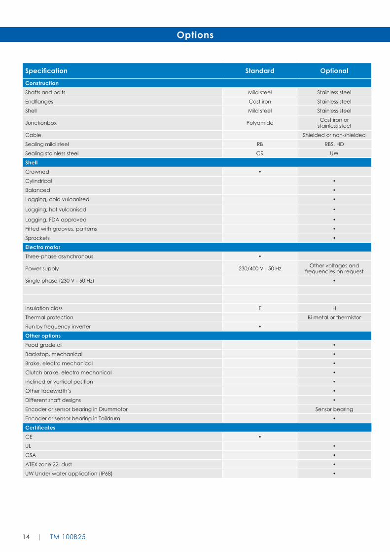
14 | TM 100B25
Specification Standard Optional
ConstructionShafts and bolts Mild steel Stainless steel
Endflanges Cast iron Stainless steel
Shell Mild steel Stainless steel
Junctionbox Polyamide Cast iron orstainless steel
Cable Shielded or non-shielded
Sealing mild steel RB RBS, HD
Sealing stainless steel CR UW
ShellCrowned •
Cylindrical •
Balanced •
Lagging, cold vulcanised •
Lagging, hot vulcanised •
Lagging, FDA approved •
Fitted with grooves, patterns •
Sprockets •
Electro motorThree-phase asynchronous •
Power supply 230/400 V - 50 Hz Other voltages and frequencies on request
Single phase (230 V - 50 Hz) •
Insulation class F H
Thermal protection Bi-metal or thermistor
Run by frequency inverter •
Other optionsFood grade oil •
Backstop, mechanical •
Brake, electro mechanical •
Clutch brake, electro mechanical •
Inclined or vertical position •
Other facewidth’s •
Different shaft designs •
Encoder or sensor bearing in Drummotor Sensor bearing
Encoder or sensor bearing in Taildrum •
CertificatesCE •
UL •
CSA •
ATEX zone 22, dust •
UW Under water application (IP68) •
Options

15TM 100B25 |
Product range
Our products, an overview
Design benefi ts
- Robust, industrial design
- Fully enclosed
- Oil fi lled
- Well-sized gears and bearings
Installation advantages
- Easy to install
- Compact and reliable
- Easy to clean
- Virtually maintenance free
- Low Life Cycle Costs
Installation advantages
- Virtually maintenance free
Drummotor type TM 100B25 TM 113B25 TM 127.25 TM 138.25 TM 160.25 TM 160.30 TM 215.30 TM 215.40
Drum diameter (mm) 100 113 127 138 160 160 215 215
Shaft diameter (mm) 25 25 25 25 25 30 30 40
Power (kW) 0.05-0.37 0.04-0.55 0.10-1.1 0.10-1.1 0.10-0.75 0.10-2.2 0.10-2.2 0.37-5.5
Speed (m/s) 0.007-3.60 0.008-4.40 0.008-2.60 0.009-2.80 0.13-3.30 0.06-4.00 0.08-5.30 0.12-4.70
Drummotor type TM 215B50 TM 273.40 TM 315.40 TM 315.50 TM 400.50 TM 400.60 TM 500.60 TM 500A75
Drum diameter (mm) 215 273 315 315 400 400 500 500
Shaft diameter (mm) 50 40 40 50 50 60 60 75
Power (kW) 1.5-4.0 0.37-5.5 0.37-5.5 1.1-11 1.1-11 1.5-22 1.5-22 11-30
Speed (m/s) 0.18-0.31 0.16-4.95 0.18-5.20 0.16-4.40 0.20-4.80 0.20-4.60 0.25-4.70 0.80-3.20
Drummotor type TM 620A75 TM 630A100 TM 800A100 TM 800A130
Drum diameter (mm) 620 630 800 800
Shaft diameter (mm) 75 100 100 130
Power (kW) 11-30 22-55 22-55 55-132
Speed (m/s) 1.00-3.90 1.00-4.00 1.25-5.10 1.60-4.50

Van der GraafPower Transmission Equipment
w w w .v a n d e r g r a a f p t e . n l
Contact usNetherlandsVan der Graaf B.V.De Weijert 14P.O. Box 38325 ZG VollenhoveTel: 00 31 527 241441Fax: 00 31 527 241488E-mail: [email protected]
USAVan der Graaf Corp.51515 CelesteShelby Township48315 MichiganTel: 00 1 866 595 3292Fax: 00 1 888 326 0089
GermanyVan der Graaf GmbHRheiner Straße 24 B48432 Rheine-MesumTel: 00 49 5975 306210Fax: 00 49 5975 3062120E-mail: [email protected]
SwedenVan der Graaf Scandinavia ABSpinngatan 2267 73 BillesholmTel: 00 46 42 22 0802Fax: 00 46 42 22 0803E-mail: [email protected]
FinlandVan der Graaf Scandinavia ABTel: 00 358 400 419063E-mail: [email protected] www.vandergraaf.fi
CanadaVan der Graaf Inc.2 Van der Graaf CourtBramptonOntario L6T 5R6Tel: 00 1 905 793 8100Fax: 00 1 905 793 812E-mail: [email protected]
Great BritainVan der Graaf U.K. Ltd.Unit 23, The Metro CentreWelbeck Way WoodstonPeterborough PE2 7UHTel: 00 44 1733 391777Fax: 00 44 1733 391044E-mail: [email protected]


