Embed Size (px)
Citation preview

1
TECHNICAL catalogue
August 2016 EDITION I
HT(PP) PIPES AND FITTINGS

Content
GENERAL NOTES 2
ABOUT COMPANY 5
1. STANDARDS THAT APPLY ON PEŠTAN HTPP PIPES AND FITTINGS 6
2. BASIC INFORMATION ABOUT PEŠTAN PP PIPES AND FITTINGS 7
3. PACKAGING, TRANSPORTATION AND STORAGE 10
4. INSTALATION AND CONNECTION 14
5. THE USE OF PIPELINES 23
6. RESOLVING OF INTERFERENCE 30
7. MAINTENANCE 31
8. DISASSEMBLY AND REMOVAL 31
9. PROCESS IN POST USING 32
10. THE LIST OF ABBREVIATION 33
11. CATALOG OF PRODUCTS 35
12. CERTIFICATES 45
13. THE TABLE OF CHEMICAL RESISTANCE 47

3
GENERAL NOTES
Tehnical catalog is subject to change in certain intervals as a result of the production of new products and modification of the same. Because of that reason it is neccesary to check if you have the latest version of tehnical catalog. Date of publication of the technical catalog is placed on the cover of the catalog and the latest version you can download from site www.pestan.net or request via mail [email protected].
Fast access sections is provided with the help of pictogram
Before starting the installation of Peštan HTPP pipes and fittings for sewerage, be sure to read all the recommendations related to safety and protection at work for your safety and the safety of people around you. All the time while you are installing system, use this tehnical instructions.In case that some of the details in this technical catalogue are not clear, please contact us on our mail : [email protected]
General safety recommendations:•Consider all the common safety rules to prevent accidents during installation of pipes and fittings
•Provide sufficient light during installation of pipes and fittings
•Keep the work area clean
•Keep away children, pets and unauthorized persons from tools and place of installation of pipes and fittings (this is especially essential in the case of renovation)
Precautions when setting up the system•If you have jewelry or other objects hanging, be sure to remove them before installing
•Cutting tools should be used and delayed in a manner to prevent injuries because they have sharp edges
•When cutting the pipe you should hold hand which is holding pipe on safe distance from cutting tools, and never do not put your hands near the area where the tool cuts pipe.
•When doing repair, maintenance or when changing place assembly, always disconnect the power supply on the tool.
Fire protectionBe sure to carefully review the cautions for fire protection as well as building regulations that apply in each special case with special emphasis on:
•Breakthrough through the ceiling, roof and walls
•Rooms with stricter requirements with prevention requirements for fire protection (review national regulations)
Personal Requirements •Only authorized and trained persons can install Peštan’s system
•Work on electrical systems or components of pipes may be executed only by persons who are trained and authorized for this purpose.
Bitne informacije
Bezbednosna preporuka
Pravna napomena

4

5
ABOT US
Private company Peštan is a leader in the Balkan in manufacturing plastic pipes and fittings for water, sewerage and gas. The company was founded in 1989 and has dealt with production of water pipes made of polyethylene. With time company has introduced new materials (polypropylene and PVC) and spread production program. Today, the offer can count over 5000 products, that includes pipes and fittings and PVC profiles, luxurious and modern drains, tape for irrigation etc. The main distribution center is located in Bukovik, near town Arandjelovac, and foreign representation are located in countries in the region: Bosnia and Herzegovina, Montenegro, Romania, Croatia, Macedonia, Bulgaria. The company is present in the market of Europe, Russia, the Middle East, North Africa, Latin America and the United States. Company is export-oriented and sales implements in over 60 countries!
The entire production is adapted to the European standards which has proven with international certificates for product quality: DVGW, MPA, SABS, IMS, IGH, ZIK, VUPS, EMI.
Working as much as possible to satisfy customer needs, the company continuously innovate and improve human resources and equipment. The introduction of WCM and WMS systems has increased efficiency, contributed to the deployment of cost and to the professional maintenance. The owner of the company, Miodrag Petković, and over 1000 employees, with joint efforts justify slogan of company: Quality. Reliablity. Inovation.

6
STANDARDS
EN 1053:1995 Plastics piping systems - Thermoplastics piping systems for non-pressure applications - Test method for watertightness
SRPS EN 681-1:2007 Elastomeric seals - Materials requirements for pipe joint seals used in water and drainage applications - Part 1: Rubber
EN 681-1:1996/A3:2005 Elastomeric seals - Material requirements for pipe joint seals used in water and drainage applications - Part 1: Vulcanized rubber
SRPS EN 12056-1:2011 Gravity drainage systems for waste water in buildings - Part 1: General requirements and performance requirements
EN 12056-1:2000 Gravity drainage systems inside buildings - Part 1: General and performance requirements
SRPS EN 12056-2:2011 Gravity drainage systems for waste water in buildings - Part 2: Sanitary pipe network, plan and budget
EN 12056-2:2000 Gravity drainage systems inside buildings - Part 2: Sanitary pipework, layout and calculation
SRPS EN 12056-3:2011 Gravity drainage systems for waste water in buildings - Part 3: Roof drainage, layout and calculation
EN 12056-3:2000 Gravity drainage systems inside buildings - Part 3: Roof drainage, layout and calculation
SRPS EN 12056-4:2011 Gravity drainage systems for waste water in buildings - Part 4: Pumping station for waste water - Plan and Budget
EN 12056-4:2000 Gravity drainage systems inside buildings - Part 4: Wastewater lifting plants - Layout and calculation
SRPS EN 12056-5:2011 Gravity drainage systems for waste water in buildings - Part 5: Installation and testing, instructions for operation, maintenance and use
EN 12056-4:2000 Gravity drainage systems inside buildings - Part 5: Installation and testing, instructions for operation, maintenance and use
SRPS EN 1451-1:2008 Piping systems of plastic for soil and waste discharge (low and high temperature) within the building structure - Polypropylene (PP) - Part 1: Specifications for pipes, fittings and the system
EN 1451-1:1998 Plastics piping systems for soil and waste discharge (low and high temperature) within the building structure - Polypropylene (PP) - Part 1: Specifications for pipes, fittings and the system
SRPS EN ISO 3126:2009 Piping systems of plastics - plastics components - Determination of dimensions
EN ISO 3126:2005 Plastics piping systems - Plastics components - Determination of dimensions
SRPS EN 744:2008 Piping systems and ducting plastics - Thermoplastics pipes - Test method for resistance to external shocks clock method
EN 744:1995 Plastics piping and ducting systems - Thermoplastics pipes - Test method for resistance to external blows by the round-the-clock method
SRPS EN ISO 2505:2013 Thermoplastics pipes - Dimensional stability during heat - Test method and parameters
EN ISO 2505:2005 Thermoplastics pipes - Longitudinal reversion - Test method and parameters
SRPS EN ISO 1133-1:2013 Plastics - Determination of the melt mass flow rate (MFR) and melt volume flow rate (MVR) thermoplastic materials - Part 1: Standard method
ISO 1133-1:2011 Plastics - Determination of the melt mass-flow rate (MFR) and melt volume-flow rate (MVR) of thermoplastics - Part 1: Standard method
SRPS EN ISO 580:2009 Piping systems and ducting plastics - Injection pressed thermo plastic fittings - Methods for visually assessing the effects of heating
ISO 580:2005 Plastics piping and ducting systems - Injection-moulded thermoplastics fittings - Methods for visually assessing the effects of heating
SRPS EN 1053:2008 Piping systems of plastic - Thermoplastic push piping systems - Test method for watertightness
Standards that apply on
Peštan HTPP pipes and fittings

7
INFORMATIONBASIC INFORMATION ABOUT PEŠTAN PP PIPES AND FITTINGS
Basic information about Peštan PP pipes and fittingsThe program HT (PP) pipes and fittings from the company Peštan is produced from PP-H (polypropylene homopolymers) by latest technology extrusion three-layer tubes per the requirements of European Standard 1451. Polypropylene has excellent mechanical and thermal properties, it doesn’t contains heavy metals and it is suitable for recycling and subsequently use for other purposes. Recyclable without loss of mechanical properties make polypropylene ecologically suitable material. Pipes and fittings from HTPP Pestan production programs are intended for soil and waste discharge (low and high temperature) within the building structure. HTPP system is universal and it can be used for drainage of contaminated water, for one-floor houses to large multiple storey buildings. Editing and manipulation of elements of the pipeline is very simple and it is described in the forthcoming chapters of this technical catalog. Connecting pipes are made via the connecting elements, the fitting, while the watertightness is provided with compound of rubber sealing rings. Inner layer of polypropylene sewage pipes has a very low roughness, resulting in good hydraulic characteristics, high resistance to abrasion, as well as to the retention of sediments and bacterial cultures for the inner wall of the pipe. For easier inspection of pipeline, inner layer of pipe is made in white color.
HTPP pipes and fitting are resistant to corrosion and their lifespan is over 50 years. Pipes and fittings possess exceptional thermal stability and they are resistant to: • short thermal loads of hot water of up to 95 ° C (30 seconds / day) • continuously up to 60 ° C (5hrs / day = 87,600 hrs / 50 years)In terms of chemical resistance HT (PP) pipes are resistant in: salt water, alcohol, acids, alkalis, sulphates, aggressive gas and all kinds of detergents. They are suitable for drainage of aggressive chemical waste, pH value of 2 (for very acid waste water) to 12 (for a very base wastewater).HT (PP) program is sensitive to waste water containing a high percentage of gasoline (petrol), benzene or acetone. For a detailed chemical resistance pipeline
look table of chemical resistance, which is an integral part of this technical catalogs.
Conection of pipes and fittings are 100% resistant to leakage up to pressure of 0.5bar (5m water column)
The pipes are not intended for outdoor use due long-term volatility during UV radiation. Also pipes are not intended for installation in the ground. It is not advisable to perform installation of pipelines on temperatures below 5 ° C.
Polypropylene has excellent sound and thermal insulating properties (far better than eg. steel). In terms of fire protection, HT (PP) pipes program belong to flammability class B2 of DIN 4102, or belong to a group of normally flammable materials.
In Peštan HTTP production program pipe is encluded:
•HTTP pipe diameter and 160 with 32,40,50,75,90,110,125 with one socket
•HTPP pipe diameter and 160 with 32,40,50,75,90,110,125 with double socket
Peštan HTPP pipes consist three layers, where each layer contributes to the desired characteristics of the product. Illustration of the layers is shown in the picture below.
Inner layer: The smooth white inner surface prevents accumulation of sediment and reduces abrasion on the pipes. It allows easier inspection of the pipeline as it is white. It is resistant to increased temperature and chemicals.
Middle layer: Reinforced mineral fillers gives strength and flexibility to the pipes.
Outer layer: Provides pipes better impact resistance, and greater security during the handling and installation of the product.
inner layer middle layer
outer layer

8
1. Barcode2. Logo3. Material4. The external diameter and wall thickness5. Class pipe S20 and the area of use B
6. Standard 7. Website8. Origin9. The time and date of manufacture
1. Logo2. Type of fitting HTB HT bend 3. Nominal diameter and degree of angle 4. Standard5. Class of fitting 6. Identification of material 7. Date
EN 1451 s20
DN 32 DN 40 DN50 DN75 DN90 DN110 DN125 DN160Dem (mm) 32 40 50 75 90 110 125 160
e(mm) min 1.8 1.8 1.8 1.9 2.2 2.7 3.1 3.9
d3(mm) min 38.6 49.6 59.6 84.5 99.5 120.5 137.5 174.3
B(mm) min 5 5 5 5 5,0 6 7 9
A(mm) min 24 26 28 33 34,0 36 38 41
L(mm) 250, 500, 100, 1500, 2000, 2500, 3000, 3500 i 4000
2.1 Marking pipes
2.2 Marking fiting:
1 2
3 4 5
6 7 98
1
2
3
4
6
5
7
Material PP-H (polypropylene homopolymer)
Pipe structure Three-layer composite pipe PPH-PPM-PPH
Density pipes (Ø32-Ø50) - 0.9 g/cm³ , pipes (Ø63-Ø160) - 0.8 g/cm³ fitting - 0.9 g/cm³
Hot water resistance short term up to 95°C long term up to 60°C
Linear expansion coefficient 0.12 mm/m°C
Chemical resistance pH 2- pH 12
E - modulus 1300-2000 MPa
Jointing method Push-fit sockets with inserted rubber ring - resistant to leakage up to pressure of 0.5bar
Application category B (instalation in buildings)
Fire classification B2 - normal inflamability
Sound insulation level 24 dB(A) sound insulation Level II

9
On each fitting is a label with a bar code. For more details, please see a detailed list of products in HTPP production program. Therefore, the basic characteristics of HT (PP) pipes are:
• Made of very light material with excellent mechanical properties
• Simple and easy transport and handling,
• Fast and inexpensive mounting, merging the end of the pipe with socket
• They are resistant to corrosion in alkaline, acid or aggressive environment,
• They are fine electrical insulator,
• They are resistant to mechanical impact,
• The lifespan is longer than 50 years
• Practically no costs of pipeline maintenance,
• The sealing rings are made from EPDM rubber per standard EN 681..
Within Peštan HTPP production programe of fittings there are included: • Bends of 15 °, 30 °, 45 °, 67.5 ° and 87.5 °from diameter Ø32 to Ø160
• Single and double branches of 67.5 ° and 87.5 ° from diameter Ø32 to Ø160
• Double sockets, sleeve sockets, reducers, inspection pipes etc ...
HTB BEND 15°
HTB BEND 87.5°
HTAE BRANCH 45°
HTU DOUBLE SOCKET
HTB BEND 35°
HTAE BRANCH 45°
HTDA DOUBLE BRANCH 67,5°
HTR EXCENTRIC REDUCER
HTB BEND 45°
HTAE BRANCH 67.5°
HTDA DOUBLE BRANCH 87,5°
HTSW FLOOR WASTE GULLY
HTB BEND 67.5°
HTAE BRANCH 87.5°
HTRE INSPECTION PIPE
HTRE NON- RETURNABLE VALVE
2.3 Production program

10
PACKAGINGPACKAGING, TRANSPORTATION AND STORAGE
Pestan HT (PP) pipes and fittings are packed in transport packages (unit and pallet) in the way convenient for customers. This way the package provides to customer safety during storage and easy
handling.
Packaging of pipesStandard packaging of HT (PP) pipes are on pallets and in packages. Pipes of all diameters in lengths of 0,25 and 0,50 meters are packed in cardboard boxes, which in a certain number, when packed up on a pallet represent the transport packaging. For creating the transport package basis used is EUR-pallet dimensions of 800 x 1200 mm.
Pipes in length 1m to 4m are packed in packages which, depending on the diameter and length, have certain noumber of pieces in unit packings and in whole packs. Every pack has certain noumber of unit packings that are packed on wooden beams and present final transport package ready for distribution to the customer.
Packaging of fittingsStandard packaging of connecting elements (fitting) are in the carton box of certain dimensions, which represent the unit of packaging, and in particular number make the transport packaging. Transport packages are formed on the EUR-pallets in dimensions 800 x 1200 mm and maximum height of 1400 mm.
Note: For accurate information regarding dimensions of packing etc. you can contact us on e mail: [email protected] .
The packaging unit (box)
The unit package (a tie)
The transport package (pack, bundle)
The transport packaging unit (pallet)
3.1 Packaging of pipes and fittings

11
Pestan HT(PP) pipes and all fittings are transported in appropriate transport vehicles. Loading area of
transporting vehicles must be clean, with no waste flat and be sure no sharp protrusions (both on the floor of vehicles and on all sides of inner part of transport vehicles).
Dimensions of pallets, packages are of dimension to fill in the space of transport vehicle.
When it comes to loading transport packages (pipes and connecting elements) with a card board
packaging, packing are so defined that in the vehicles with height of 2.9 meters of cargo space can fit two packings- one on top of other.
When loading transport packaging of pipes in packages, depending on the diameter of the pipe, the packages are packed in height in two or more levels. Pipe diameters ø75 to diameter ø160 are packed in two levels in height (height of the load compartment must be at least 2.9 meters).
Pipes diameters ø32 to ø50 are packed to transport vehicle into four levels according to overall height. (height of the loading area must be at least 2.9 meters).
When it comes to loading pipes outside the transport packaging (bulk), the pipe along its length must rely on a flat surface to avoid deformation of the same. The joints must therefore be alternately twist and pull for their entire length. This primarily has to be taken into account when pipes are of bigger length, in their case mishandling could lead to bending pipes at the end. When loading and unloading pipes, they should not be mishandled, pulled, pushed, especially on concrete and other rough surfaces. Any bending must be prevented, especially in the case of very low outside temperatures (temperatures below freezing).
3.2 Transportation and manipulation

12
3.3 StoragePeštan HT(PP) pipes and fittings packed in card board packings are specifically stored in closed space (Shelf warehouses, one pallet – one pallet space).
Peštan HT(PP) pipes and fittings packed in card board packings are specifically stored in closed space (Shelf warehouses, one pallet – one pallet space).
If there is not a shelf warehouse, recomendation is that transport packings as these are stored in closed space and in one level (do not put pallet on top of another).
When there is no ransportation packing but the goods arrived to customer in unit packs, they should be stored on pallets that are dry and clean. Boxes can be piled up one on another. Boxes musn’t be packed out of pallet or to be backed without a base that can hold them.
For storage of transport packaging of HT(PP) pipes and fittings, warehouses need to meet certain conditions.
Recommendation for storage:• Transport packaging should be stored in dry, clean, indoors, where the temperature is between 10 and 30 ° C and a relative humidity between 50 and 60%.
• They should be protected from direct sunlight, moisture and heat and also need to be protected from the high temperature fluctuations as this may lead to occurrence of condensation and loss of functional properties of cardboard boxes.
Pestan HT (PP) pipes length from 1 to 4 meters can be stored in closed and in the open area. When pipes are stored in the open, that area should be protected from direct influence of sunlight by protective UV stable foil or canopy. It is recommended that these and transportation packaging are stored in an enclosed space, or space that is shaded.
No matter where are stored, whether indoors or outdoors, the packages should not be stacked in more than one level (from ø75 to diameter ø160), and not more than two levels of pipes diameters of ø32 to diameter ø50.
Although withstanding high temperatures it is not recommended long-term storage of pipes near a heat source. In addition to this it is strictly required to ensure that the pipe during storage does not
come into contact with materials damaging for polypropylene (eg. motor fuel, solutions, wood preservatives).
In the case of bulk pipes (or single pieces packages) attention should be paid to the following:
• pipes should be stored on a flat surface
• pipes should be placed on the wooden beams so the sockets of the pipe would not touch the surface and get deformed.
• pipes should not be dropped, dragged and pushed on uneven surfaces during stacking.
• pay attention to the way of stacking pipes (alternately rotate pipes so the sockets on the ends are
free and therefore do not allow their deformation).
• ensure that packed pipes are secured from the sides.
• height of stacked pipes must not exceed a height of 1.5 meter
• pipes are to be stored indoors if there are conditions, if not pipes are stored in a shaded area or
cover with UV stable protective film.

13
Wooden beams for underlying pipes should not be narrower than 8 cm and the thickness should not be thinner of 5 cm.
Axial spacing between the beams depending on the diameter and the length of the pipes ranges from 400 to 1000 mm, while the pipe overhang also depending on the diameter and length of the pipes also varies from 200 to 500 mm.

14
INSTALLATIONINSTALLATION AND CONNECTION
Peštan’s pipes and fittings are installed in accordance with EN 12056 Gravity drainage systems inside buildings.
If there is a specific regulation within certain countries, which deviates from the norms mentioned, be sure to consult Peštan before installing.
4.1 Types of pipelinesTo properly comprehend the connection and installation of interior installations for drainage of used water is necessary to explain the types of pipelines, which are part of a system for drainage of water use. The main classification of pipelines is as follows:
Connecting line from building to the streetThis connection line is a line that leads from the building to terminal on a street circuit. It should be as short as possible and straighter.
Connecting line for the places where water is flowingConnecting line is a pipeline to connect the pouring places (VC cup, bidet, sink, ...). Diameter of pipline defines a number and type of the pouring places to join him. Connecting cables are mainly installed in grooves, in the walls and floors and closed with mortar or sleeve. The lines of this type can be installed in specially designated channels and can be closed by prefabricated elements, allowing easier access to the pipeline system when changing. Connecting lines also can be hung under the plate, that means for the ceiling of the room, which is located below, via clamps.There is another way of installing the connecting piping, which is mounting in cavity walls (plaster sandwich walls) and hanging by clips for constructive elements of sandwich walls. Connecting lines must not be longer than 3 m and must have a fall of minimum 3%. Connecting seats with the casting pipeline is realized via a siphon to prevent the return of odors from the sewage network. Connecting lines should be as short as possible and straighter.
The vertical line (“vertical”)The vertical line is placed vertically (so it got its name) and its purpose is to connect the first type of connecting lines with a second type of connection line. Pestan recommends the use of non-return valves at the connection places.Scheme of non-return valve installation is given on page n.20. Lines of this type are usually placed inside the walls and closed with mortar or placed in channels, relying on clamps. Placing pipes in the trench allows easier access to the pipeline for maintenance. In the case of plastic piping connections between the vertical line and the connection line is realized through two elbow of 45 .̊ In buildings with more than three floors, cascade is installed to vertical pipe in order to reduce water consumption. Cascade is performed so as to draw the line elbow angle of 90˚ in the length of 250 mm, than it comes back in the vertical direction by elbow at an angle of 90 .̊ Before elbow, reducer is being installed and after restoring water into vertical direction and by reducing piece returns to its original diameter. In this way, excessive force of water is avoided which would occur at the connecting point of the vertical and the connection line.
The vertical line should have a ventilation hole at its highest point. Pestan can offer venting device, which helps the unpleasant smells to go out through the hole that is outside. Ventilation of vertical line can be: primary and secondary.

15
Display of the vertical with primary ventilation
Display of the vertical with secondary ventilation
Display of the vertical with secondary ventilation
Ventilation in tall buildings
VENTILATIONSECONDARY VENTILATIONPRIMARY VENTILATION
PRIMARY VENTILATION
ROOF ROOF
ROOF
3rd floor 3rd floor
3rd floor 12th floor
8th floor
4th floor
Ventilation
2nd floor 2nd floor
2nd floor
1st floor 1st floor
1st floor
Ground floor Ground floor
Ground floor
Ground floor

16
4.2 Pipes connectingElements of PP internal sewerage are connected by sockets and rubbers, which enables waterproof elements connection. Gluing pipes is not recommended. All pipes and fittings have at least one socket on the end. Peštan has also the pipes with 2 sockets on offer. Pipes without sockets can be connected by double sockets and sleeve sockets. Pipes can be cut by using a special blade for pipe or hand saw blades with fine teeth, as shown on the picture below.
Fitting cannot be cut
Cutting pipes has to be done perpendicularly to pipe axis. The cut end of the pipe must be cleaned and skew. Skew of end of the pipe that was cut is achieved by fine sandpaper or a fine rasp. There are special tools for cutting, which during the cutting make a fine shape of the end of pipe. The table below shows the dimensions of the slope of pipe end.
Use all safety precautions
After preparation of cut pipe or connecting fabric pieces without cutting, it is required to do next:
1. Clean a socket and flat part of a pipe. Cleaning should be done by dry or damp cloth.
2. After cleaning of pipe, condition of sealing elements should be inspected.
3. After cleaning and checking a condition of sealing elements, the flat end of the pipe should be lubricated. Peštan’s lubricants are recommended for this purpose. Lubricants based on oil, cannot be used. Socket and rubber seal should be dry and clean and they are not coated with a lubricant.
Slope length
DN 32 40 50 75 90 110 125 160
b(mm) 3,5 3,5 3,5 3,5 4.0 4,5 5,0 6,0
Review of required length of pipe diameter slope
Display of cleaning the pipe ends
Pipe cuting at the angle of 15°
Display of sleeve with sealing rubber band
Display of lubricant applying.
15°
b

17
When installing pipelines, comes to cutting pipes which results in the appearance of the remains of the pipe which don’t have sockets (pipe smooth on both sides). The figure below shows the way of connection pipeline with sleeve sockets and pipes without sockets. In this case the pipe without socket that is installed between the two connectors must have a minimum length of twice the nominal diameter ... For example, if the diameter is 160mm, than the minimum length of pipes without socket must be 320mm.
Also, while installing pipeline, where there are remains of pipes without socket, it should be noticed that length of the remains shouldn’t be more than 3m. For such an installation, it is required to ensure enough quantity of sleeve sockets and double sockets, and certain quantity of clamps with profiled rubber bands.On picture below, a difference in installation of remains of pipes without socket, with double and sleeve socket. More about pipeline
reliance during installation in the next section.
4. After using a lubricant at the flat part of a pipe, it should be inserted into socket. Than mark entry depth and pull out a pipe cca 10mm. In this way a free working space is left while thermal dilatation. When working with pipes of max 2m length, pulling out the pipes for 10mm is quite enough. In case of using longer pipes (4m for example), lyre should be performed or to accept dilatations by changing the direction- in that case, flat ends are completely inserted into sockets.
4.3 Connecting pipes and fittings
Review of inserted pipe into socket I pulling out in order to leave a space for dilatation pipe work
Review of regularly inserted pipe into socket.
Sleev socket
Pipe without sleeve da - pipe diameter
1
2

18
4.4 Pipelines reliancePipelines reliance may be continuous or reliance in points. In case of installation of pipelines in the wall of the building, it is called continuous reliance, and pipeline reliance through the clamp is called pipelines in points.
Continuous pipeline relianceThis kind of reliance provides support for the pipeline along its entire length. These are pipelines placed inside the masonry walls and floor structures and panels. Penetrations through walls and grooves for the pipeline, which are closed by mortar must ensure installation of pipelines without voltage on pipeline and potential-free condition of the pipeline during the settlement of the building. Built-in pipeline, by the mode of installation should be protected from mechanical influences.
Full pipe elements must be placed in the breach. Connection between the pipes shouldn’t be in the breach. In the case of polypropylene pipes for internal canalization, closing pipes by mortar can be done immediately after the assembly and installation of insulation, however it is not recommended to close the pipeline before checking water resistance, because in this way the immediate inspection of pipelines is disabled.
In case that the sewer pipe is near the water pipe, which transports warm water, both should be thermal isolated in accordance with applicable standards.
It’s requred with horizontal lines to support them throughout the length when installing in the floor, and at the same time the ability to compensate for temperature dilatation must be provided.
Pipeline reliance in pointsWhen pipelines reliance in points, the pipelineis not support ed throughout, and therefore terms of reliance of pipes, should be defined. There are two types of point supports by way of reliance:• Fixed (FT)• moving (KT)Fixed supports prevent the moving in all directions, and must be located below all sockets of the pipeline, ie in the case of pieces of pipes with both flat end, fixed bearing is installed on a double socket or sleeve socket. It should be noted that the fixed supports don’t allow elongation of pipes, therefore it is necessary to position the supports in the way which enables that between two fixed support there is an element for compensation of the elongation of pipe (socket, if installed as described above or compensating element if the dilatation can not accept by space left in the socket).
1.Double socket 2. Sleev socket
3. Fixed point (holder) 4. Sleev socket (holder)
Recommended spacing of holders
DNFor horisontal pipeline (m)
For vertical pipeline (m)
32 0,50 1,2
40 0,50 1,2
50 0,50 1,5
75 0,80 2,0
90 0,95 2,0
110 1,10 2,0
125 1,25 2,0
160 1,60 2,0
Display of recommended spacing of supports for piping according to pipe diameter, distances are related to supports in general, while the preference for fixed or sliding support is
performed according to the aforementioned criteria.
Also, while installing pipeline, where there are remains of pipes without socket, it should be noticed that length of the remains shouldn’t be more than 3m. For such an installation, it is required to ensure enough quantity of sleeve sockets and double sockets, and certain quantity of clamps with profiled rubber bands.
On picture below, a difference in installation of remains of pipes without socket, with double and sleeve socket. More about
pipeline reliance during installation in the next section.

19
•Fixed (FT)• Motional (KT)floor joists (ceiling)
Pipes through the basic
ceiling and the ceiling
Example of spacing of supports for the horizontal line, where the rule of 10 ø valid for diameters DN50 mm and larger.
KT - sliding point (sliding support); FT - fixed point (fixed bearing)
4.5 Pipes through the ceiling
Pipes through the basic ceiling and the ceiling must be soundproof and waterproof. The use of a KGF pieces for pipes through the ceiling is recomended, in order to ensure waterproofing of the joint. When through floor joists of smaller diameters, the waterproofing can be provided with mineral fiber, PP insulating foam or bitumen.
In case of need the security of the spread of fire, there are special measures that can be taken about it. It is possible to set the pipe in refractory sleeves, these sleeves are placed on the side of a mezzanine structure where a higher risk of fire.
4.6 Installing pipes in concrete
HT (PP) pipes Peštan can be installed without problems in the concrete, if one takes into account the longitudinal dilatation. When watering pipes in the concrete should be well secured, to prevent a relocation of the pipeline during the installation of concrete. It should also be ensured and pipe joints protective tape to prevent leakage of cement to seal elements.
Installing pipes in concrete and display protection
compound from penetrating cement
4.7 Installing devices to prevent flooding in buildings – Non-returnable valve
Non-return valves are installed in pipelines where there is a possibility of returning water from the street sewage in the building due to the increase of water in the sewage system and to prevent the entry of rodents and other animals through sewer pipes. As previously stated Pestan recommends the use of non-return valves on the connection of vertical lines on the connection line.
Non-return valves are fitted with an automatic closing flap in the flow of water from suprotkog direction in relation to the intended flow of water.
The basic postulate of installation
• Non-return valves are installed in smaller manholes easily Avaliable for cleaning the device.
• When cleaning do not use objects with sharp edges.
• The maximum allowed drop when setting the check valve is 2%.
The following figure shows the installation scheme of non-return valve.
Hard paper cardboard Concrete
Base

20
4.8 Measures to reduce noise
According to DIN 4109 noise resulting from pipeline, built-in sound-protected areas should not exceed 35 dB. The aforementioned reasons, the pipes should not be visibly guided in these areas. The pipes are led through the designated channels, if the wall surface weight greater than 220kg / m2. Further noise reduction is achieved by using clamps with rubber inserts and using the plastic plugs for the fastening clamp to the wall. In the case that these measures do not bear fruit in the required extent, we recommend using Peštan
S LINE (low-noise) pipe systems.
Displey of transition from vertical in horizontal line(for zones of low permissible noise)
Installation scheme.
4.9 Firefighting measuresBehavior of Pestan’s HT (PP) pipes and fittings during the fire is fully in accordance with DIN 4102, under which are classified in class B2 (normal flammability class). Preventive fire protection that prevents the penetration of smoke and gases through the pipe insulation is an absolute obligation for each multi-storey building. According to the latest European standards, when pipelines cross through walls and floor structures it is necessary to use special clamp that prevents the spread of fire through the pipeline to other rooms in the house. Always use a tested and proven suppliers.
In cases when a fire occurs, a plastic tube under the influence of temperatures become soft and deformed. At the same time, at temperatures greater than 150 ° C, special fire protection laminate expands and increases its volume by up to 10 times. When spread within the metal part clamps, pressure laminate tube, around which the clamp is set, pressing up to 10bar. As a result of this pressure, in just a few minutes, fire laminate fully squeezes the plastic pipe, sealing thus breach the walls or floor construction. This leads to preventing the spread of flames and smoke through the pipes inside buildings, between rooms.
When installing the fire protection clamp in place pipe penetrations through the floor construction should know that the clamps can be installed during construction or later, after building.

21
Installation scheme.
Installation of fire collars for mezzanine structure (during construction)
Installation of the sleeve to the basic structure (after construction)
Installation of fire collars on the walls
Mounting angle fire collars (only to basic ceiling)
4.10 Testing of pipelinesTesting of internal sewage forking can be divided into three categories:
• technical inspections,
• Test water resistance
• Test on gas resistance
The pipeline must not overlap prior to the execution of the test, all connections must be visible and clear. All openings must be temporarily closed during the test water resistance. The water with which the watertightness is tested should be dry. Overpressure testing water tightness ranges from a minimum of 0.03 bar to maximum 0.5 bar. Tightness test takes an hour. Criteria for passing the test water resistance is to not lose more than 0.5 liters / hour for every 10 m2 of the inner surface of pipelines.
The pipeline is tested after assembly and connecting the casting elements and tested in segments. The segments are isolated by audit openings. It should be borne in mind that the greatest pressure occurs at the lowest point segment of the pipeline, which is being tested, and that took the place of the maximum allowable pressure of 0.5 bar . Installation of fire collars for mezzanine structure (during construction) Installation of the sleeve to the basic structure (after construction) The obligation of every builder is to make a record rehearsals pipeline and under these conditions, the warranty provided by the company Pestan.
When installing the fire protection clamp in place pipe penetrations through walls is necessary to install two clips (on both sides of the wall).
As for the mounting clamps penetration sealing angle, it should be noted that such a clamp is installed only on pipes through ceiling joists..
Observe local regulations regarding the prevention
And localization of fires inside buildings.

22
Sewage usage
Display of loose and tight clamps on pipesBuka koja se prenosi vazduhom (Airborn noise)
Buka koja se prenosi preko zidova objekata (Structure-borne noise)
NOISE REDUCTION
Pestan S LINE pipes and fitting are installed in accordance with EN 12056 gravitational drainage system inside of buildings. If a special regulation exists in other country and is different than norm it is necessary to consult Pestan about it before the installation. In every area of edification sond isolation is every day more and more important. The pipe lines that transport fluids are one of the most frequent noise sources in buildings.
Both types of noise can be reduced to a minimum in different ways. Airborne noise is reduced by producing the pipes and fittings in special manner of special materials with special mineral additives o by optimizing the usage of fittings on spots where pipelines change direction. On direction changing spots it is recommended to use the elbows 45°and a pipe 25mm instead of an elbow 87.5°, so the level of noise made by flow and direction change can be reduced to maximum.
Structure-borne noise is decreased by properly installing the pipeline with quality clamps with profiled rubber on (fixed points) also by optimized tightening of clamps (sliding spots).
5.1 Noise reduction measures There are 2 types of noise differed by what brings it:
• Airborne noise
• Structure-borne noise
Airborne noise is transmitted by air, and it comes from within the pipeline, it is the consequence of the fluid flow inside of the pipes. Pestan systems with its special design are limiting this noise level by keeping it inside the pipe.
Structure-borne noise is transmitted over the object walls. Vibrations occur during the fluid flow trough the pipe and fittings over the clamp and onto the building walls making irritating noise. With using the right clamps with profiled rubber of known producers and with proper installation of Pestan system of low nose pipes and fittings, this type of noise is reduced to a minimum.
The transition from a vertical to a horizontal line (For zones of low allowable noise)

23
Display of system Installationin the Fraunhofer Institute
Acoustic clip 110110/110/45°
110/110/90°
Installation wall
220kg/m²
Acoustic clip 110
branch 45°
110/110/45°
Acoustic clip
110
Acoustic clip 110
water inlet
water outlet
Acoustic bracket 110
MR(b)
GF(b) GF(f)
MR(f)
TF(b) TF(f)
200
400
2800
200
400
2800
Diagram
of results
23-9 page
Niskošumna
16dB
PP (HT)
24dB
Metalna
35dB
5.2 Lab testing of sound isolation To certify efficiency of sound isolation, system of pipes and fittings for house sewage Pestan Low Noise system is sent for testing to german Fraunhofer institute for construction physics.
Testings are made by EN 14366 norm (Laboratory measurement of noise from waste
water installations) and by DIN 4109 (Sound insulation in buildings – Requirements
and verifications), according to which the noise level must not surpass 35dB (A) in apartment building that require greater sound isolation.
Testings are made by EN 14366 norm (Laboratory measurement of noise from waste
water installations) and by DIN 4109 (Sound insulation in buildings – Requirements
and verifications), according to which the noise level must not surpass 35dB (A) in apartment building that require greater sound isolation. Testing is made under the flow 1.0 / 2.0 and 4.0 L/sec.
Test made with Pestan Low Noise pipe system has proven much better results of noise isolation than any other regular HT PP

24
The measurement results with commercial pipe clamp, “BISMAT 2000”, behind a wall in the basement.
Ln – noise level dB(A)
Q – flow rate L/sec
* - the maximum allowednoise level by DIN 4109
5
2 l/s
Lln[dB (A)]
4 l/s
10
15
20
25
30
35
24
31
VDI 4100
DIN 4109*
Q [L/s]
PEŠTANHTPP
Source: LSC,A [dB(A)] Fraunhofer test report P-BA 93/2016e
Results achieved during the test with Pestan HTPP pipe system (behind the wall of 220kg/m² and minimal thickness of 115mm plus mortar), a with different flows they gave the following diagram.
Efficiency confirmation of elimination of fore mentioned problems of noise inside of pipe systems Pestan emitted by Fraunhofer, where by measuring was established that level of noise generated inside of Pestan pipe system is 24dB (under the fluid flow 2l/s(DN110). Pestan HTPP pipes are wanted in buildings where noise level reduction is requiered on minimum, such as hospitals, schools, libraries, dormitories etc.)

25
5.3 Level of sound isolation and calssification
90
Nivo I zvučne izolacije – zahtevi prema DIN 4109 korespondiraju sa 30 dB(A)
Nivo II zvučne izolacije – viši nivo zvučne izolacije korespondira sa 25 dB(A)
Nivo III zvučne izolacije – najviši nivo zvučne izolacije korespondira sa 20 dB(A)
Nivo I zvučne izolacije – porodične kuće
Nivo II zvučne izolacije – apartmanske zgrade, stambene i poslovne zgrade manje spratnosti
Nivo III zvučne izolacije – hoteli, bolnice, biblioteke, čitaonice, stambeni kompleksi
•
•
•
•
•
•
Prema VDI 4100, postoji tri stepena zvučne izolacije, u zavisnosti od namene objekta u kome su cevi instalirane:
VDI nivoi zvučne izolacije i klasifikacija:
On family houses
Sound insulation level I or on agreement
Apartment bulidings, residential and office buildings, comfort apartments
Sound insulation level II or higher
Hotels, hospitals, residential complexes
Sound insulation level III enhanced agreements
According to VDI 4100 there are 3 degrees in sound isolation, depending on the purpose of object in which the pipes are installed:
*Level 1 DIN 4109 corresponds to 30dB (A)
*Level 2 corresponds to 25dB (A)
*Level 3 corresponds to 20 dB (A)
VDI level of sound isolation and class
*Level 1 - Family house
*Level 2 - apartment building and offices
*Leve 3 - Hotels, hospitals, libraries, living complexes
Family house Apartment building and offices
Hotels, hospitals, libraries, living complexes
Level I of sound isolation Level II of sound isolation
Level III of sound isolation

26
USAGEUSAGE OF PIPELINES
Pestan HT (PP) program is primarily designed for internal distribution systems for the evacuation of used water in residential buildings. Because of the areas of application of these systems, as part of this chapter will be explained by way of sizing the interior times with water drainage water use residential buildings.
Hydraulic design of culverts consists of two parts:
• Empirical part
• Calculation
Empirical part The empirical part deals with the dimensioning of the pipe horizontal fork and collecting the used waters from the casting, ie, the connecting cables. This part of the calculation is done empirically because of the frequency of a large number of factors that the water binding capacity of influence, ie, variability in flow of waste water, the variability of the flow rate naravnomernost, diversity sanitary equipment (pouring seats), variability of the number of people using the facilities, a variety of long time use building and the presence of air and gases in the network. The following table shows the diameter by area of use
Diameter of pipe
(mm)Place of use
DN 50 1. only in the upper branches of the arrester for connecting one to two sinks arrester
DN 751. In the upper branches of the arrester as a continuation of the confluence of three or more sinks2. As an offshoot of the arrester stack for bathroom and shower3. As a vertical upper surge sinks and urinals
DN 110
1. Vertical upper arrester for latrines2. Branch vertical arrester for latrines and pomijare3. As a horizontal underside of the upper surge arrestors (vertical) of detention for washing and kitchen wastewater4.As the upper vertical arrester of toilets in basement walls and under the floor of the basement to the horizontal lower arrester horizontalnog donjeg odvodnika
DN 1251. Vertical arrester of rainwater2. Eventually as the upper vertical arrester for a very large number of the closet3. As the lower arresters compound rain pipe drain
DN 160
1. . The upper arrester (vertical) for a large number of group lavatory on the floors2. As an offshoot of the upper arrester for the group urinals in a row3. Horizontal lower sink for all of the above urinals4. As a major arrester home network
application areas of different diameters

27
CalculationThe computational part refers to the determination of the diameter of the compound’s main distribution channel (vertical) with street, ie. Computing part refers to the budget of connecting cables. Calculation of the connecting line is also validated the main internal waters, ie vertical water for buildings. For this purpose it is necessary first to determine the
The volume of water consumption (production waste water) Consumption of one resident per day (1 / day)
In temperate (small) water consumptionv 50-70
When sufficient (high) water consumption 70-150
When plentiful (large) water consumption 150-500
Determination of the quantity of waste water according to the number of tenants
Type of sanitary facility duration of use
One use of toilet 10-15 min.
One showering 45 min.
One bath 60 min.
One wash 5-10 min.
The use of the urinal 1-3 min.
One use of the bidet 3-5 min.
The duration of use of sanitary appliances
Type of sanitary facility From one use(l)
Per hour(l) Per day
WC sa visokim kotlićem 7,0According to frequency of use according to usage period
washbasin 3,0
urinal 4,0
Bathtub 180,0
shower 70,0
bidet 3,0
basins 20,0
the fountain in the kitchen 180,0
sink 250,0
The quantity of wastewater production by type of sanitary facilities
amount of wastewater flow in liters per second (l / s). The quantity wastewater flow affect the volume of consumption of drinking water in the house, and the volume of water consumption is influenced by: type, type of building, number of occupants, number and type of sanitary facilities. The following tables presents information about germ wastewater for a variety of building and sanitary kits.

28
Type of building Type of deviceProduction of
one person per day
Residental buildings with normal sanitary devices 125 - 150
with exceptional sanitary devices 150 - 300
Social buildings with normal sanitary devices 80 - 120
hotels 250 - 400
Public buildings Schools with the necessary device 12
Schools with the complete device 21
Various government offices with normal device 15
Hospitals (per bed) 250 - 500
Sanatoriums (per bed) 230 - 400
Ambulance (per patient) 6
Kindergarden (per kid) 50 - 75
With necessary device (per worker per shift) 10 - 25
With necessary device (per worker per shift) 10
The amount of waste water by type of building
name Unit of consumptionLiters per day
per unitLiters per hour
per unit
canteen From making one meal 10 - 25 -
canteen From one tap - 250
public baths From one bath 125 - 180 -
public baths From one tap - 500 - 800
laundries with mechanical drive From one kg of dry laundry 60 - 75 -
Laundries with manual drive From one kg of dry laundry 35 -
public restroom From one toalete place 350 - 600 -
Public urinals with constant rinsing From one urinal place - 200
Buffets From one tap - 120
Taverns From one tap - 300
Pharmacies From one tap 60 -
laboratories From the table with 5-7 sits - 1500 - 2000
medical offices From the time of receipt of patients - 30 - 40
berberine From one work table with washbasin 75 -
Garages From one car washing 700 -
Stables
From one horse 50 -
From one ox 40 -
From one pig 13 -
From one sheep 8 -
Waste water for economic buildings and stores
Because for using above given table is necessary to know the exact user habits and beause the calculation on this way is complicated, we suggest using the methods described below.

29
Calculation of dimensioning of the connecting line according to SamingTo determine the diameter of the connecting line it is needed, of the total daily amount of wastewater, to calculate the flow rate of wastewater per second. For this purpose the method of the calculation by
Saming can be useful. With this method comes a new set of tables. The following table shows the amount of effusion of individual sanitary facilities, reduced to the equivalent factor K.
For unit is taken outflow from one water faucets of ø 1/2 “. The amount of outflow is calculated in liters / sec. In another table are given the percentages of
approved coincident outflow equivalent accessories for adequate number of the same and according to purpose of building. This number is indicated by P.
Type of the outflow object Equivalent K Outflow amount q’’
u lit./ sec. u lit./min.
Faucet 1 0,33 20
Toilet with high rinsing 3,6 1,20 -
Toilet with low rinsing 6,0 2,00 -
Urinal 0,5 0,17 10
Washbasin- bathroom sink 0,5 0,17 10
Kitchen sink 2,0 0,67 40
Bathtub 2,0 0,67 40
Shower 0,7 0,22 14
Bidet 0,5 0,15 10
Small faucet 0,25 0,08 5
Outflow amount of sanitary objects
Residential buildings Social buildings
NK P NK P NK P NK P
do 10 19,8 do 160 5,0 do 10 14,3 do 100 4,5
do 15 16,2 do 180 4,7 do 12 12,9 do 120 4,1
do 20 14,0 do 200 4,4 do 14 12,0 do 140 3,8
do 25 12,6 do 250 4,0 do 16 11,2 do 160 3,6
do 30 11,5 do 300 3,6 do 18 10,5 do 180 3,4
do 35 10,6 do 350 3,4 do 20 10,0 do 200 3,2
do 40 9,9 do 400 3,1 do 25 9,0 do 250 2,8
do 45 9,4 do 450 3,0 do 30 8,2 do 300 2,6
do 50 8,9 do 500 2,8 do 35 7,6 do 350 2,4
do 60 8,1 do 600 2,6 do 40 7,1 do 400 2,2
do 70 7,5 do 700 2,4 do 45 6,7 do 500 2,0
do 80 7,1 do 800 2,2 do 50 6,3 do 600 1,8
do 90 6,6 do 900 2,1 do 60 5,8 do 700 1,7
do 100 6,3 do 1000 2,0 do 70 5,4 do 800 1,6
do 120 5,7 do 1500 1,6 do 80 5,0 do 900 1,5
do 140 5,3 do 2000 1,4 do 90 4,7 do 1000 1,4
Percentage of concurrent outflow of the same facilities; NK-product coefficient K with the same number of outlet facilities N.

30
Using the data in these tables and the number outflow places, collected by types and groups of verticals, the second amount of effusion loading of the main house connecting pipeline is obtained. This quantity is calculated according to the formula:
Where are:
After determining the total quantity of waste water and flow rate in liters / second, access to the selection of the appropriate diameter of the hydraulic tables provided in the next section..
Selection of appropriate diameter is performed according to the following criteria:
• Main home line must be a minimum DN 160 mm
• Occasionally, during the day, it must have a speed of 0.7 m / s for self-cleaning pipes
Since HT (PP) Pestan program has no larger diameters from DN 160 mm, for the purposes of increasing the connecting line is recommended to use Pestan PVC pipe systems. Peštan’s PVC product range is compatible with HT(PP) product range, therefore these two kind of pipelines can be combined.
In further table, the flow of the pipe HT (PP) DN 160 with different longitudinal falls is shown. If there is a request for a bigger diameter, you can find all details in PVC technical instructions, where you can find hydraulic table for PVC pipes.
For the flows for partial fulfillment of flow profile, please use hydraulic table 2.
First you need to determine flow through the pipeline, assume fall and find appropriate one by test of coefficients of fulfillment cross section. Take care that flow for the selected fall at complete fulfillment of profiles (Hydraulic Table 1) is greater than one which we seek.
Example of calculating according to saming:First we need to count all inlet objects of the same type, and then make a tabular review, as shown below:
Types of sanitary equipment
Number of equipment
across verticals
The total number of the same
equipment
The equivalent factor K for an equipment on
the table
Of the factors K and N to
the number of equipment
which determines the
percentage of P
The total number of
equipment N
Percentage P simultaneous
effusion of the total number of equivalent
equipment
Quantity effusion qn Lit / sec. for appropriate equipment
The total quantity of
effusion Q Lit / sec
13 15
The toilets (WC) - 2 2 3,6 7,2 0,474
Sinks - 2 2 0,5 1,0 0,067
Bathtubs - 2 2 2,0 4,0 0,265
Small faucet 1 - 1 0,25 0,25 0,016
Kitchen sink - 2 2 2,0 4,0 0,265
Total Q= 1,087
Example of calculating
Q - second quantity of flow of waste water,
N - number of objects of the same type,
P - the percentage of simultaneous effusion the same objects and
qn - quantity of effusion of individual objects in liters / second.

31
DN (mm) 160 DN (mm) 160 DN (mm) 150 DN (mm) 160 DN (mm) 160
Type of pipe
sdr41Type of
pipesdr41
Type of pipe
sdr41 Klasa cevi sdr41Type of
pipesdr41
Hydraulic Table 1: different falls for HT (PP) pipes DN 160 mm k = 0.50
I (‰) v (m/s) Q (L/s) I (‰) v( m/s) Q (L/s) I (‰) v( m/s) Q (L/s) I (‰) v( m/s) Q (L/s) I (‰) v( m/s) Q (L/s)
0,1 0,092 1,672 4,9 0,719 13,034 9,7 1,018 18,471 19 1,433 25,989 28,6 1,762 31,965
0,2 0,134 2,437 5 0,726 13,169 9,8 1,024 18,568 19,2 1,441 26,127 28,8 1,769 32,078
0,3 0,167 3,031 5,1 0,734 13,303 9,9 1,029 18,664 19,4 1,448 26,264 29 1,775 32,190
0,4 0,195 3,533 5,2 0,741 13,436 10 1,034 18,760 19,6 1,456 26,401 29,2 1,781 32,302
0,5 0,219 3,977 5,3 0,748 13,568 10,2 1,045 18,950 19,8 1,463 26,537 29,4 1,787 32,414
0,6 0,241 4,380 5,4 0,755 13,698 10,4 1,055 19,138 20 1,471 26,673 29,6 1,793 32,525
0,7 0,262 4,751 5,5 0,762 13,828 10,6 1,066 19,325 20,2 1,478 26,808 29,8 1,799 32,636
0,8 0,281 5,096 5,6 0,769 13,956 10,8 1,076 19,509 20,4 1,485 26,942 30 1,806 32,747
0,9 0,299 5,421 5,7 0,776 14,083 11 1,086 19,692 20,6 1,493 27,075 30,5 1,821 33,021
1 0,316 5,728 5,8 0,783 14,208 11,2 1,096 19,873 20,8 1,500 27,208 31 1,836 33,294
1,1 0,332 6,021 5,9 0,790 14,333 11,4 1,106 20,053 21 1,507 27,340 31,5 1,851 33,564
1,2 0,347 6,301 6 0,797 14,457 11,6 1,115 20,231 21,2 1,515 27,472 32 1,865 33,832
1,3 0,362 6,569 6,1 0,804 14,580 11,8 1,125 20,408 21,4 1,522 27,603 32,5 1,880 34,098
1,4 0,376 6,828 6,2 0,811 14,701 12 1,135 20,583 21,6 1,529 27,733 33 1,895 34,362
1,5 0,390 7,077 6,3 0,817 14,822 12,2 1,144 20,757 21,8 1,536 27,863 33,5 1,909 34,624
1,6 0,404 7,319 6,4 0,824 14,942 12,4 1,154 20,929 22 1,543 27,992 34 1,923 34,884
1,7 0,416 7,553 6,5 0,830 15,061 12,6 1,163 21,100 22,2 1,550 28,120 34,5 1,938 35,143
1,8 0,429 7,780 6,6 0,837 15,178 12,8 1,173 21,269 22,4 1,558 28,248 35 1,952 35,399
1,9 0,441 8,001 6,7 0,843 15,295 13 1,182 21,437 22,6 1,565 28,376 35,5 1,966 35,653
2 0,453 8,217 6,8 0,850 15,412 13,2 1,191 21,604 22,8 1,572 28,502 36 1,980 35,906
2,1 0,465 8,427 6,9 0,856 15,527 13,4 1,200 21,770 23 1,579 28,629 36,5 1,994 36,157
2,2 0,476 8,632 7 0,862 15,641 13,6 1,209 21,934 23,2 1,585 28,754 37 2,007 36,406
2,3 0,487 8,833 7,1 0,869 15,755 13,8 1,218 22,097 23,4 1,592 28,880 37,5 2,021 36,654
2,4 0,498 9,029 7,2 0,875 15,868 14 1,227 22,259 23,6 1,599 29,004 38 2,035 36,900
2,5 0,508 9,221 7,3 0,881 15,980 14,2 1,236 22,420 23,8 1,606 29,128 38,5 2,048 37,144
2,6 0,519 9,410 7,4 0,887 16,091 14,4 1,245 22,580 24 1,613 29,252 39 2,061 37,387
2,7 0,529 9,595 7,5 0,893 16,202 14,6 1,254 22,739 24,2 1,620 29,375 39,5 2,075 37,628
2,8 0,539 9,776 7,6 0,899 16,312 14,8 1,262 22,896 24,4 1,626 29,498 40 2,088 37,868
2,9 0,549 9,955 7,7 0,905 16,421 15 1,271 23,053 24,6 1,633 29,620 40,5 2,101 38,106
3 0,559 10,130 7,8 0,911 16,529 15,2 1,280 23,208 24,8 1,640 29,741 41 2,114 38,343
3,1 0,568 10,303 7,9 0,917 16,637 15,4 1,288 23,363 25 1,647 29,863 41,5 2,127 38,578
3,2 0,577 10,473 8 0,923 16,744 15,6 1,297 23,516 25,2 1,653 29,983 42 2,140 38,812
3,3 0,587 10,640 8,1 0,929 16,851 15,8 1,305 23,669 25,4 1,660 30,103 42,5 2,153 39,044
3,4 0,596 10,804 8,2 0,935 16,956 16 1,313 23,820 25,6 1,666 30,223 43 2,166 39,275
3,5 0,605 10,967 8,3 0,941 17,061 16,2 1,322 23,971 25,8 1,673 30,342 43,5 2,178 39,505
3,6 0,613 11,127 8,4 0,946 17,166 16,4 1,330 24,120 26 1,680 30,461 44 2,191 39,734
3,7 0,622 11,284 8,5 0,952 17,270 16,6 1,338 24,269 26,2 1,686 30,579 44,5 2,203 39,961
3,8 0,631 11,440 8,6 0,958 17,373 16,8 1,346 24,417 26,4 1,693 30,697 45 2,216 40,187
3,9 0,639 11,594 8,7 0,964 17,476 17 1,354 24,564 26,6 1,699 30,814 45,5 2,228 40,411
4 0,648 11,745 8,8 0,969 17,578 17,2 1,362 24,710 26,8 1,705 30,931 46 2,240 40,635
4,1 0,656 11,895 8,9 0,975 17,679 17,4 1,370 24,855 27 1,712 31,048 46,5 2,253 40,857
4,2 0,664 12,043 9 0,980 17,780 17,6 1,378 25,000 27,2 1,718 31,164 47 2,265 41,078
4,3 0,672 12,189 9,1 0,986 17,880 17,8 1,386 25,143 27,4 1,725 31,280 47,5 2,277 41,298
4,4 0,680 12,334 9,2 0,991 17,980 18 1,394 25,286 27,6 1,731 31,395 48 2,289 41,516
4,5 0,688 12,477 9,3 0,997 18,080 18,2 1,402 25,428 27,8 1,737 31,510 48,5 2,301 41,734
4,6 0,696 12,618 9,4 1,002 18,178 18,4 1,410 25,569 28 1,744 31,624 49 2,313 41,950
4,7 0,703 12,758 9,5 1,008 18,277 18,6 1,418 25,710 28,2 1,750 31,738 49,5 2,325 42,166
4,8 0,711 12,897 9,6 1,013 18,374 18,8 1,425 25,850 28,4 1,756 31,852 50 2,337 42,380

32
Q/Qpp h/d v/vpp Q/Qpp h/d v/vpp Q/Qpp h/d v/vpp Q/Qpp h/d v/vpp Q/Qpp h/d v/vpp Q/Qpp h/d v/vpp
Hydraulic Table 2: Ratios of the amount of water flow and the flow velocity HT (PP) sewerage pipes in partial fulfillment profile
0,001 0,023 0,17 0,045 0,141 0,52 0,21 0,309 0,80 0,51 0,506 1,00 0,805 0,701 1,08 0,955 0,856 1,05
0,002 0,032 0,21 0,05 0,149 0,54 0,22 0,316 0,81 0,52 0,512 1,01 0,81 0,705 1,08 0,960 0,865 1,04
0,003 0,038 0,24 0,055 0,156 0,55 0,23 0,324 0,82 0,53 0,519 1,01 0,815 0,709 1,08 0,965 0,874 1,04
0,004 0,044 0,26 0,06 0,163 0,57 0,24 0,331 0,83 0,54 0,525 1,02 0,82 0,713 1,08 0,970 0,883 1,04
0,005 0,049 0,28 0,065 0,170 0,58 0,25 0,339 0,84 0,55 0,531 1,02 0,825 0,717 1,08 0,975 0,894 1,03
0,006 0,053 0,29 0,07 0,176 0,59 0,26 0,346 0,85 0,56 0,537 1,02 0,83 0,721 1,08 0,980 0,905 1,03
0,007 0,057 0,30 0,075 0,182 0,60 0,27 0,353 0,86 0,57 0,543 1,03 0,835 0,725 1,08 0,985 0,919 1,02
0,008 0,061 0,32 0,08 0,188 0,61 0,28 0,360 0,86 0,58 0,550 1,03 0,84 0,729 1,07 0,990 0,935 1,02
0,009 0,065 0,33 0,085 0,194 0,62 0,29 0,367 0,87 0,59 0,556 1,03 0,845 0,734 1,07 0,995 0,956 1,01
0,01 0,068 0,34 0,09 0,200 0,63 0,3 0,374 0,88 0,6 0,562 1,04 0,85 0,738 1,07 1,000 1,000 1,00
0,011 0,071 0,35 0,095 0,205 0,64 0,31 0,381 0,89 0,61 0,568 1,04 0,855 0,742 1,07
0,012 0,074 0,36 0,1 0,211 0,65 0,32 0,387 0,89 0,62 0,575 1,04 0,86 0,747 1,07
0,013 0,077 0,36 0,105 0,216 0,66 0,33 0,394 0,90 0,63 0,581 1,05 0,865 0,751 1,07
0,014 0,080 0,37 0,11 0,221 0,67 0,34 0,401 0,91 0,64 0,587 1,05 0,87 0,756 1,07
0,015 0,083 0,38 0,115 0,226 0,68 0,35 0,407 0,92 0,65 0,594 1,05 0,875 0,761 1,07
0,016 0,086 0,39 0,12 0,231 0,69 0,36 0,414 0,92 0,66 0,600 1,05 0,88 0,766 1,07
0,017 0,088 0,39 0,125 0,236 0,69 0,37 0,420 0,93 0,67 0,607 1,06 0,885 0,770 1,07
0,018 0,091 0,40 0,13 0,241 0,70 0,38 0,426 0,93 0,68 0,613 1,06 0,89 0,775 1,07
0,019 0,093 0,41 0,135 0,245 0,71 0,39 0,433 0,94 0,69 0,620 1,06 0,895 0,781 1,07
0,02 0,095 0,41 0,14 0,250 0,72 0,4 0,439 0,95 0,7 0,626 1,06 0,9 0,786 1,07
0,022 0,100 0,42 0,145 0,255 0,72 0,41 0,445 0,95 0,71 0,633 1,06 0,905 0,791 1,07
0,024 0,104 0,43 0,15 0,259 0,73 0,42 0,451 0,96 0,72 0,640 1,07 0,91 0,797 1,07
0,026 0,108 0,45 0,155 0,263 0,74 0,43 0,458 0,96 0,73 0,646 1,07 0,915 0,803 1,06
0,028 0,112 0,45 0,16 0,268 0,74 0,44 0,464 0,97 0,74 0,653 1,07 0,92 0,808 1,06
0,03 0,116 0,46 0,165 0,272 0,75 0,45 0,470 0,97 0,75 0,660 1,07 0,925 0,814 1,06
0,032 0,120 0,47 0,17 0,276 0,76 0,46 0,476 0,98 0,76 0,667 1,07 0,93 0,821 1,06
0,034 0,123 0,48 0,175 0,281 0,76 0,47 0,482 0,99 0,77 0,675 1,07 0,935 0,827 1,06
0,036 0,127 0,49 0,18 0,285 0,77 0,48 0,488 0,99 0,78 0,682 1,07 0,94 0,834 1,05
0,038 0,130 0,50 0,19 0,293 0,78 0,49 0,494 1,00 0,79 0,689 1,07 0,945 0,841 1,05
0,04 0,134 0,50 0,2 0,301 0,79 0,5 0,500 1,00 0,8 0,697 1,07 0,95 0,849 1,05

33
Resolving of interference
During exploitation, with any piping system there are the potential for interference. Interference in the case of sewage pipeline are possible in the form of clogging and leaks of pipelines, and therefore when installing you should predict inspectional hatch for inspection of pipelines and cleaning if there is need for it.
INTERFERENCE

34
MAINTENANCE
DEINSTALLATIONDismantling and removal
As mentioned in Section 7, there should be inspections in mind. In terms of maintenance, we distinguish between regular maintenance and emergency maintenance.
Emergency maintenance includes replacement of certain elements of pipelines in case of damage or cleaning pipeline when it comes to clogging. The regular maintenance includes cleaning of pipelines and waste layers on the pipe walls. Cleaning and disinfection of the pipeline should be carried out by organizations or institution that is competent and accredited for this type of works.
Dismantling and removal of the pipeline is done in the following manner, that is by the following procedure:
• drain the water from the system
• if the pipeline is guided in the walls of the building, prepare th walls so as to release the pipeline that is planned to be removed.
• dismantle the pipeline by separating the connections
• dismantled pipeline, if necessary, should be cut into shorter pieces for easier manipulation
• dismantled and cut pipes should be loaded on transport vehicle and taken to a landfill intended for plastic mass, so that the material can be recycled.

35
POST USAGE
PP
POST USAGE PROCEDURE
As mentioned earlier, polypropylene plastic material, which are used for production of HT (PP) pipe, can be recyclable. The recycling of polypropylene does not lose its physicochemical properties, so that the recycled material can be used for the purpose of coating the motor housing, producing laundry basket and any plastic items.Peštan uses original material manufactured by renowned manufacturers for creation of the HTPP production program of pipes and fittings. While recycling , plastic materials are sorted by code, so the code for polypropylene is as follows:

36
ABBREVIATIONSList of Abbreviations
Metric system of measuring units (SI) is used, for example. Units of force Newton (N) instead of pounds (p) and power unit Watt (W) instead kcal / h.
Conversion:
Thermal conductivity is given in W /mK. Division unit is the same for K and C because the difference is just at the beginning of the scale. In this sense, 1 W / m ° C is identical to 1 W /mK. K (Kelvin) is the SI unit of temperature. The temperature in Celsius (t) differs from the temperature in Kelvin (T) to 273.15 K.
.
in this document , f g is equal to 10 m/s, the error of approximately 2% was ignored. DN indicates the nominal diameter and PN indicates nominal pressure.
1 kp = 9.80665 N ili 1 kp ≈ 10 N1 Mp = 9806.65 N ili 1 Mp ≈ 10 kN i 1 Mp/m = 10 kN/m
1 kp/cm2 = 9.80665 N/cm2 = 0.0980665 N/mm2 = 0.0980665 Mpa ili 1 kP/cm2 ≈ 0.1 N/mm21 m vodenog stubs = 0.0980665 bar ili 1 m vodenog stuba ≈ 0.1 bar
1 kcal/m h step-in = 1.16 W/mK (thermal conductivity) ili 1 kcal/mh degrees ≈ 1.2 W/mK
t (°C) = T – To = T – 273.15 K.
37
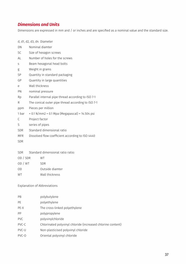
Dimensions and UnitsDimensions are expressed in mm and / or inches and are specified as a nominal value and the standard size.
d, d1, d2, d3, d4 Diameter
DN Nominal diamter
SC Size of hexagon screws
AL Number of holes for the screws
s Beam hexagonal head bolts
g Weight in grams
SP Quantity in standard packaging
GP Quantity in large quantities
e Wall thickness
PN nominal pressure
Rp Parallel internal pipe thread according to ISO 7-1
R The conical outer pipe thread according to ISO 7-1
ppm Pieces per million
1 bar = 0.1 N/mm2 = 0.1 Mpa (Megapascal) = 14.504 psi
C Project factor
S series of pipes
SDR Standard dimensional ratio
MFR Dissolved flow coefficient according to ISO 4440
SDR
SDR Standard dimensional ratio ratio:
OD / SDR WT
OD / WT SDR
OD Outside diamter
WT Wall thickness
Explanation of Abbreviations
PB polybutylene
PE polyethylene
PE-X The cross-linked polyethylene
PP polypropylene
PVC polyvinylchloride
PVC-C Chlorinated polyvinyl chloride (increased chlorine content)
PVC-U Non-plasticised polyvinyl chloride
PVC-O Oriental polyvinyl chloride

38
CHEMICAL RESISTANCETABLE OF POLYPROPYLENE CHEMICAL RESISTANCE
11.1 Introduction
This document’s table sums up polypropylene chemical resistancy data, used in various countries, formed as a result of practical experience and tests.
Source: ISO/TR 10358
Table consists of chemical resistancy evaluation for the vast number of fluids estimated as aggressive or intern towards polypropylene. Evaluation is based upon values gained from results of sinking the polypropylene into fluid sample test, under the temperature 20, 60 and 100C and atmospheric pressure, and upon following the specifics of the tensile strenght under the circumstances.
Classification will be estimated with taking account of limited number of fluids considered technically or commercially important, using all the equipment that allows you testing under the pressure and coefficiency determination of chemical ressistancy for every fluid separately. In this manner, these tests will provide complete information about use of polypropylene pipes for transport of the mentioned fluids including their use under the pressure.
11.2 Application area
This document contains classification of Polypropylene chemical ressistancy for about 180 fluids. It is ment to provide general instructions about possibilities of using polypropylene pipes for fluid conduction.
*Under temperatures of 20, 60 and 100C
*Under deficiency of inner pressure and outer mechanical tension (example: bending tension, pressure tension, distortion tension etc.)
11.3 Definitions and symbols as abbreviationsCriteria classifications, definitions, symbols of abbreviations used in this section are as follows:
S – satisfactory L –partial or limited
The chemical resistance of polypropylene to exposed activities fluids are classified as partially satisfactory when the test results were confirmed in most of the countries that participated in the test.
Also, this classification (L) is used for the resistance to chemical activity of the fluid in which the dependence of the parameters can be used i S i NS.
NS – not satisfactory
The chemical resistance of polypropylene exposed to fluid activity is classified as not satisfactory when the test results are confirmed in most of the countries that participated in the test.
In this classification (NS) are materials that, depending on the parameters are marked with NS or L.
Saturated - saturated aqueous solution, prepared at 20 ° C
Aqueous solution -unsaturated at concentrations higher than 10%
Diluted solution - diluted aqueous solution at concentrations equal to or lower than 10%
A working solution - water solution with normal concentration for industrial use
Solution concentrations recorded in the text are expressed in percentages by weight. Aqueous solutions of poorly soluble chemicals to which the chemical activities of the polypropylene business, considered saturated solutions. Overall, in this catalog were used common chemical names. This table napravravljena as a guide for users of polypropylene. In the case that a chemical compound is not in the table, due to uncertainties related to the chemical resistance in an application, please contact Pestan for advice and testing proposal.

39
Chemical or Product Concentration Temperature °C
20 60 100
Acetic acid up to 40 % S S -
Acetic acid 50% S S L
Acetic acid, glacial >96% S L NS
Acetic anhydride 100% S - -
Acetone 100% S S -
Aceptophenone 100% S L -
Acrylonitrile 100% S - -
Air - S S S
Allyl alcohol 100% S S -
Almond oil - S - -
Alum Sol S S -
Ammonia, aqueous Sat. sol S S -
Ammonia, dry gas 100% S - -
Ammonia, liquid 100% S - -
Ammonium acetate Sat. sol S S -
Ammonium chloride Sat. sol S S -
Ammonium fluoride up to 20% S S -
Ammonium hydrogen carbonate Sat. sol S S -
Ammonium metaphosphate Sat. sol S S S
Ammonium nitrate Sat. sol S S S
Ammonium persulphate Sat. sol S S -
Ammonium phosphate Sat. sol S - -
Ammonium sulphate Sat. sol S S S
Ammonium sulphide Sat. sol S S -
Amyl acetate 100% L - -
Amyl alcohol 100% S S S
Aniline 100% S S -
Apple juice - S - -
Aqua regia HCl/HNOF3/1 NS NS NS
Barium bromide Sat. sol S S S
Barium carbonate Sat. sol S S S

40
Chemical or Product Concentration Temperature °C
20 60 100
Barium chloride Sat. sol S S S
Barium hydroxide Sat. sol S S S
Barium sulphide Sat. sol S S S
Beer - S S -
Benzene 100% L NS NS
Benzoic acid Sat. sol S S -
Benzyl alcohol 100% S L -
Borax sol S S -
Boric acid Sat. sol S - -
Boron trifluoride Sat. sol S - -
Bormine, gas - NS NS NS
Bromine, liquid 100% NS NS NS
Butane, gas 100% S - -
Butanol 100% S L L
Butyl acetate 100% L NS NS
Butyl glycol 100% S - -
Butil fenol Sat. sol S - -
Butyl phenols 100% S L L
Calcium carbonate Sat. sol S S S
Calcium chlorate Sat. sol S S -
Calcium chlorate Sat. sol S S S
Calcium hydroxide Sat. sol S S S
Calcium hypochlorite sol S - -
Calcium nitrate Sat. sol S S -
Camphor oil - NS NS NS
Carbon dioxide, dry gas - S S -
Carbon dioxide, wet gas - S S -
Carbon disulphide 100% S NS NS
Carbon monoxide, gas - S S -
Carbon tetrachloride 100% NS NS NS
Castor oil 100% S S -
Caustic soda Up to 50% S L L
Chlorine, aqueous Sat. sol S L -
Chlorine, dry gas 100% NS NS NS

41
Chemical or Product Concentration Temperature °C
20 60 100
Chlorine, liquid 100% NS NS NS
Chloroacetic acid 100% S - -
Chloroethanol 100% S - -
Chloroform 100% L NS NS
Chlorosulphonic acid 100% NS NS NS
Chrome alum Sol S S -
Chromic acid Up to 40% S L NS
Citric acid Sat. sol S S S
Coconut oil - S - -
Copper (Il) chloride Sat. sol S S -
Copper (Il) nitrate Sat. sol S S S
Copper (Il) Sat. sol S S -
Corn oil - S L -
Cottonseed oil - S S L
Cresol Greater than 90% S - -
Cyclohexane 100% S - -
Cyclohexanol 100% S L -
Cyclohexanone 100% L NS NS
Decalin (decahydronaphthalene) 100% NS NS NS
Dextrin Sol S S -
Dextrin Dextrose Sol S S S
Dibutyl phthalate 100% S L NS
Dichloroacetic acid 100% L - -
Dichloroethytene (A and B) 100% L - -
Diethanolamine 100% S - -
Diethyl ether 100% S L -
Diethylene glycol 100% S S -
Diglycolic acid 100% S - -
Diisooctyl 100% S L -
Dimethyl amine, gas - S - -
Dimethyl formamide 100% S S -
Dioctyl phthalate 100% L L -
Dioxane 100% L L -
Distilled water 100% S S S

42
Chemical or Product Concentration Temperature °C
20 60 100
Ethyl alcohol Up to 95% S S S
Ethyl chloride, gas - NS NS NS
Ethylene chloride (mono and di) - L L -
Ethyl ether 100% S L -
Ethylene glycol 100% S S S
Ethanolamine 100% S - -
Ethyl acetate 100% L NS NS
Ferric chloride Sat. sol S S S
Ferric chloride Formaldehyde 40% S - -
Formic acid 10% S S L
Formic acid 85% S NS NS
Formic acid, anhydrous 100% S L L
Fructose Sol S S S
Fruit juice - S S S
Gasoline. petrol (aliphatic hydrocarbons) - NS NS NS
Gelatine - S S -
Glucose 20% S S S
Glycerine 100% S S S
Glycolic acid 30% S - -
Heptane 100% L NS NS
Hexane 100% S L -
Hydrobromic acid More than 48% S L NS
Hydrochloric acid More than 20% S S S
Hydrochloric acid 30% S L L
Hydrochloric acid From 35 to 36% S - -
Hydrofluoric acid Dil.sol S - -
Hydrofluoric acid 40% S - -
Hydrogen 100% S - -
Hydrogen chloride, dry gas 100% S S -
Hydrogen peroxide Up to 10% S - -
Hydrogen peroxide Up to 30% S L -
Hydrogen sulphide, dry gas 100% S S -
Iodine, in alcohol - S - -

43
Chemical or Product Concentration Temperature °C
20 60 100
Isoctane 100% L NS -
Isopropyl alcohol 100% S S S
Isopropyl ether 100% L - -
Lactic acid Up to % S S -
Lanoline - S L -
Linseed oil - S S S
Magnesium carbonate Sat. Sol S S S
Magnesium chloride Sat. Sol S S -
Magnesium hydroxide Sat. Sol S S -
Magnesium sulphate Sat. Sol S S -
Maleic acid Sat. Sol S S -
Mercury (Il) chloride Sat. Sol S S -
Mercury (Il) cyanide Sat. Sol S S -
Mercury (I) nitrate Sol S S -
Mercury 100% S S -
Methyl acetate 100% S S -
Methyl alcohol 5% S L -
Methyl amine Up to 32% S - -
Methyl bromide 100% NS NS NS
Methyl ethyl ketone 100% S - -
Methylene chloride 100% L NS NS
Milk - S S S
Monochloroacetic acid <85% S S -
Naphtha - S NS NS
Nickel chloride Sat. Sol S S -
Nickel nitrate Sat. Sol S S -
Nickel sulphate Sat. Sol S S -
Nitric acid Up to 30% S NS NS
Nitric acid From 40 to 50% L NS NS
Nitric acid, fujming (with nitrogen dioxide) - NS NS NS
Nitrobenzene 100% S L -
Oleic acid 100% S L -

44
Chemical or Product Concentration Temperature °C
20 60 100
Oleum (sulphuric acid with 60 % of S03) - S L -
Olive oil - S S L
Oxalic acid Sat. Sol S L NS
Oxygen, gas - S - -
Parafin oil (FL65) - S L NS
Peanut oil - S S -
Peppermint oil - S - -
Perchloric acid (2N) 20% S - -
Petroleum ether (ligroine) - L L -
Phenol 5% S S -
Phenol 90% S - -
Phosphine, gas - S S -
Phosphoric acid Up to 85% S S S
Phosphorus oxychloride 100% L - -
Picric acid Sat. Sol S - -
Potassium bicarbonate Sat. Sol S S S
Potassium borate Sat. Sol S S -
Potassium bromate Up to 10% S S -
Potassium bromide Sat. Sol S S -
Potassium carbonate Sat. Sol S S -
Potassium chlorate Sat. Sol S S -
Potassium chlorite Sat. Sol S S -
Potassium chromate Sol S S -
Potassium cyanide Sat. Sol S - -
Potassium dichromate Sat. Sol S S S
Potassium ferricyanide Sat. Sol S S -
Potassium fluoride Up to 50% S S -
Potassium hydroxide Sat. Sol S S S
Potassium iodide Sat. Sol S - -
Potassium nitrate 10% S S -
Potassium perchlorate (2N) 30% S S -
Potassium permanganate Sat. Sol S - -
Potassium persulphate Sat. Sol S S -

45
Chemical or Product Concentration Temperature °C
20 60 100
Potassium sulphate 100% S S -
Propane, gas <50% S - -
Propionic acid - S - -
Pyridine 100% L - -
Seawater - S S S
Silicon oil - S S S
Silver nitrate Sat. Sol S S L
Sodium acetate Sat. Sol S S S
Sodium benzoate 35% S L -
Sodium bicarbonate Sat. Sol S S S
Sodium carbonate Do 50% S S L
Sodium chlorate Sat. Sol S S -
Sodium chloride Sat. Sol S S -
Sodium chlorite 2% S L NS
Sodium chlorite 20% S L NS
Sodium dichromate Sat. Sol S S S
Sodium hydrogen carbonate Sat. Sol S S S
Sodium hydrogen sulphate Sat. Sol S S -
Sodium hydrogen sulphite Sat. Sol S - -
Sodium hydroxide 1% S S S
Sodium hydroxide From 10 to 60% S S S
Sodium hypochlorite 5% S S -
Sodium hypochlorite From 10 to 15% S - -
Sodium hypochlorite 20% S L -
Sodium metaphosphate Sol S - -
Sodium nitrate Sat. Sol S S -
Sodium perborate Sat. Sol S S -
Sodium phosphate (neutral) - S S S
Sodium silicate Sol S S -
Sodium sulphate Sat. Sol S S -
Sodium sulphate Sat. Sol S - -
Sodium sulphite 40% S S S
Sodium thiosulphate (hypo) Sat. Sol S - -
Soybean oil - S L -

46
Chemical or Product Concentration Temperature °C
20 60 100
Succinic acid Sat. Sol S S -
Sulphuric acid Up to 10% S S S
Sulphuric dioxide, dry or wet 100% S S -
Sulphur acid From 10 to 30% S S -
Sulphur acid 50% S L L
Sulphur acid 96% S L NS
Sulphur acid 98% L NS NS
Sulphurous acid Up to 30% S - -
Tartaric acid Sat. Sol S S -
Tetrahydrofuran 100% L NS NS
Tetralin 100% NS NS NS
Thiophene 100% S L -
Tin (IV) chloride Sol S S -
Tin (Il) chloride Sat. Sol S S -
Toluene 100% L NS NS
Trichloroacetic acid Up to 50% S S -
Trichloroethylene 100% NS NS NS
Triethanolamine Sol S - -
Turpentine NS NS NS
Urea Sat. Sol S S -
Vinegar - S S -
Water brackish, mineral, potable - S S S
Whiskey S S -
Wines S S -
Xylene 100% NS NS NS
Yeast Sol S S S
Zinc chloride Sat. Sol S S -
Zinc sulphate Sat. Sol S S -

47
The information contained in this catalog to our the information is accurate and reliable as of the day of publication. Peštan does not provide a guarantee and gives no explanation for accuracy or completeness of the information contained here, and assumes no liability in connection with the consequences of their use or for any misprint. Our products are intended for general consumption. The responsibility of the buyer is to inspect and test our products in order to ascertain the suitability of the product for customer’s particular purpose. The buyer is also responsible for appropriate, safe and legal use, processing and handling our product. Here, nothing provides a guarantee. There is no liability that can be accepted and refers to the use of Peštan products in conjunction with other materials. The information contained in this catalog refers exclusively to our products when not used in conjunction with any third party.
Peštan points out that data on the chemical resistance of Polypropylene displayed in the list of chemical resistance in this catalog are based on data collected from several sources. Peštan does not guarantee the correctness and accuracy such data and accepts no liability of any loss or damage as a result of use, inability to use or the result of using catalog by the customer or any third party to whom such data can be transmitted. You are obliged to enable suitable test to ensure convenience and safety products for the intended use in accordance with applicable regulations.
Disclaimer

48
CERTIFICATES

49

50
PRODUCTION PROGRAMHT(PP) pipes & fitting up to Ø32 do Ø160
Name Image Code d Z1 Z2 L1min
HTB Bend 15°
10200300 32 3 5 39
10200301 40 4 7 44
10200302 50 5 9 46
10200304 75 7 11 51
10200308 110 9 14 58
10200309 125 10 14 82
HTB Bend 35°
10200500 32 8 13 39
10200501 40 14 14 44
10200502 50 9 12 46
10200508 110 17 21 58
10200509 125 10 15 15
10200510 160 29 23 23
HTB Bend 45°
10200600 32 9 12 42
10200601 40 10 14 44
10200602 50 12 16 46
10200604 75 18 21 51
10200608 110 25 29 58
10200609 125 28 33 64
10200610 160 42 36 94
HTB Bend 67.5°
10200700 32 13 16 42
10200701 40 16 19 44
10200702 50 19 23 46
10200704 75 28 32 51
10200708 110 40 46 58
10200709 125 45 50 82
10200710 160 64 58 94
HTB Bend 87.5°
10200800 32 19 23 42
10200801 40 23 26 44
10200802 50 28 31 46
10200804 75 40 43 51
90
10200808 110 57 57 58
10200809 125 65 65 64
10200810 160 89 83 94

51
Name Image Code d Z1 Z2 L1min
HTB Bend 15°
10200300 32 3 5 39
10200301 40 4 7 44
10200302 50 5 9 46
10200304 75 7 11 51
10200308 110 9 14 58
10200309 125 10 14 82
HTB Bend 35°
10200500 32 8 13 39
10200501 40 14 14 44
10200502 50 9 12 46
10200508 110 17 21 58
10200509 125 10 15 15
10200510 160 29 23 23
HTB Bend 45°
10200600 32 9 12 42
10200601 40 10 14 44
10200602 50 12 16 46
10200604 75 18 21 51
10200608 110 25 29 58
10200609 125 28 33 64
10200610 160 42 36 94
HTB Bend 67.5°
10200700 32 13 16 42
10200701 40 16 19 44
10200702 50 19 23 46
10200704 75 28 32 51
10200708 110 40 46 58
10200709 125 45 50 82
10200710 160 64 58 94
HTB Bend 87.5°
10200800 32 19 23 42
10200801 40 23 26 44
10200802 50 28 31 46
10200804 75 40 43 51
90
10200808 110 57 57 58
10200809 125 65 65 64
10200810 160 89 83 94
sewerageHT(PP)

52
Name Image Code d Z1 Z2 Z3 L1min
HTEA Branch 45°
10200900 32/32 9 40 40 42
10200901 40/32 5 46 44 44
10200902 40/40 10 49 49 44
10200903 50/32 -1 53 49 46
10200904 50/40 5 56 54 46
10200905 50/50 12 61 61 46
10200912 75/50 -1 79 74 51
10200914 75/75 18 91 91 51
90/90z
10200938 110/50 -17 104 91 58
10200940 110/75 1 116 109 58
10200944 110/110 25 134 134 58
10200953 125/110 18 144 141 64
10200954 125/125 28 152 152 64
10200963 160/110 1 168 159 81
10200965 160/160 36 194 194 81
HTEA Branch 67.5°
10201000 32/32 13 27 27 42
10201002 40/40 16 33 33 44
10201005 50/50 19 40 40 46
10201038 110/50 9 72 52 58
10201044 110/110 40 85 85 58
HTEA Branch 87.5°
10201100 32/32 19 21 21 42
10201101 40/32 19 25 21 44
10201102 40/40 23 25 25 44
10201103 50/32 19 30 21 46
10201104 50/40 23 30 25 46
10201105 50/50 28 30 30 46
10201112 75/50 27 43 31 51
10201114 75/75 40 43 43 51
10201138 110/50 28 60 32 58
10201140 110/75 40 60 45 58
10201144 110/110 57 62 62 58
10201153 125/110 58 69 63 64
10201154 125/125 65 70 70 64
10201164 160/125 66 87 71 81
10201165 160/160 83 89 89 81
Name Image Code d Z1 Z2 Z3 L1min
HTEA Branch 45°
10201505 50/50/50 12 61 61 46
10201538 50/110/50 -17 104 91 58
10201544 110/110/110 25 134 134 58
HTEA DOUBLE BRANCH 67,5°
10201605 50/50/50 19 40 40 46
10201638 50/110/50 9 72 52 58
10201644 110/110/110 40 85 85 58
HTEA DOUBLE BRANCH 87,5°
10201738 50/50/50 28 30 30 46
10201744 50/110/50 28 60 32 58
HTRE INSPECTION PIPE
10201402 50 32 30 46
10201404 75 48 43 51
10201408 110 58 62 58
10201409 125 58 62 64

53
Name Image Code d Z1 Z2 Z3 L1min
HTEA Branch 45°
10200900 32/32 9 40 40 42
10200901 40/32 5 46 44 44
10200902 40/40 10 49 49 44
10200903 50/32 -1 53 49 46
10200904 50/40 5 56 54 46
10200905 50/50 12 61 61 46
10200912 75/50 -1 79 74 51
10200914 75/75 18 91 91 51
90/90z
10200938 110/50 -17 104 91 58
10200940 110/75 1 116 109 58
10200944 110/110 25 134 134 58
10200953 125/110 18 144 141 64
10200954 125/125 28 152 152 64
10200963 160/110 1 168 159 81
10200965 160/160 36 194 194 81
HTEA Branch 67.5°
10201000 32/32 13 27 27 42
10201002 40/40 16 33 33 44
10201005 50/50 19 40 40 46
10201038 110/50 9 72 52 58
10201044 110/110 40 85 85 58
HTEA Branch 87.5°
10201100 32/32 19 21 21 42
10201101 40/32 19 25 21 44
10201102 40/40 23 25 25 44
10201103 50/32 19 30 21 46
10201104 50/40 23 30 25 46
10201105 50/50 28 30 30 46
10201112 75/50 27 43 31 51
10201114 75/75 40 43 43 51
10201138 110/50 28 60 32 58
10201140 110/75 40 60 45 58
10201144 110/110 57 62 62 58
10201153 125/110 58 69 63 64
10201154 125/125 65 70 70 64
10201164 160/125 66 87 71 81
10201165 160/160 83 89 89 81
Name Image Code d Z1 Z2 Z3 L1min
HTEA Branch 45°
10201505 50/50/50 12 61 61 46
10201538 50/110/50 -17 104 91 58
10201544 110/110/110 25 134 134 58
HTEA DOUBLE BRANCH 67,5°
10201605 50/50/50 19 40 40 46
10201638 50/110/50 9 72 52 58
10201644 110/110/110 40 85 85 58
HTEA DOUBLE BRANCH 87,5°
10201738 50/50/50 28 30 30 46
10201744 50/110/50 28 60 32 58
HTRE INSPECTION PIPE
10201402 50 32 30 46
10201404 75 48 43 51
10201408 110 58 62 58
10201409 125 58 62 64
sewerageHT(PP)

54
Name Image Code d Z1 I
HTU DOUBLE SOCKET
10202300 32 94
10202301 40 103
10202302 50 103
10202304 75 109
10202308 110 122
10202309 125 138
HTU SLEEVE SOCKET
10202400 32 94
10202401 40 103
10202402 50 103
10202404 75 109
10202408 110 122
10202409 125 138
HTR REDUCER
10201200 40/32 10 44
10201201 50/32 16 46
10201202 50/40 12 46
10201208 75/50 20 51
10201230 110/50 40 58
10201232 110/75 26 58
10201244 125/110 15 64
10201253 160/110 34 81
10201254 160/125 27 81
HTM END CAP
10202200 32
10202201 40
10202202 50
10202204 75
10202208 110
10202209 125
10202210 160
10202211 200
HT VENTING DEVICE
10202705 50 106 94
10202700 75 143 119
10202701 110 168 110
10202703 160 253 150
Name Image Code d D h l L1
HTSW FLOOE WASTER GULLEY
10202104 50 50,6 32,8 71 80
HTSW FLOOE WASTER GULLEY TYPE 2
10202101 32 46 26 51 61
10202103 40 46 26 51 75
HTSW FLOOE WASTER GULLEY TYPE 1
10202100 32 53,7 26 51 61
10202102 40 53,7 26 51 75
Name Image Code(Metal grid)
Code(Plasic grid) d A B C D H H1
HT HORIZONTAL DRAIN
10299910 10299000 50 150 150 192 139,5 46,5 12,5
10299920 10299002 75 150 150 195 160 56,5 12,5
Name Image Code(Metal grid)
Code(Plastc grid) d A B C D H H1
HT VERTICAL DRAIN
10299911 10299001 50 150 150 125 60 12,5
10299921 10299003 75 200 200 160 130 9
- 10299005 110 200 200 160 130 9
- 10299010 110 250 250 200 85 12
Name Image Code d S L1 L2 L3 L4
HTRE NON RETURNABLE VALVE
10202500 50 2,2 50 40 197 98
10202501 75 2,5 70 54 265 139
10202502 110 4,0 64 64 320 189
10202503 125 4,0 68 65 318 226
10202504 160 4,0 68 103 350 248

55
Name Image Code d Z1 I
HTU DOUBLE SOCKET
10202300 32 94
10202301 40 103
10202302 50 103
10202304 75 109
10202308 110 122
10202309 125 138
HTU SLEEVE SOCKET
10202400 32 94
10202401 40 103
10202402 50 103
10202404 75 109
10202408 110 122
10202409 125 138
HTR REDUCER
10201200 40/32 10 44
10201201 50/32 16 46
10201202 50/40 12 46
10201208 75/50 20 51
10201230 110/50 40 58
10201232 110/75 26 58
10201244 125/110 15 64
10201253 160/110 34 81
10201254 160/125 27 81
HTM END CAP
10202200 32
10202201 40
10202202 50
10202204 75
10202208 110
10202209 125
10202210 160
10202211 200
HT VENTING DEVICE
10202705 50 106 94
10202700 75 143 119
10202701 110 168 110
10202703 160 253 150
sewerageHT(PP)
Name Image Code d D h l L1
HTSW FLOOE WASTER GULLEY
10202104 50 50,6 32,8 71 80
HTSW FLOOE WASTER GULLEY TYPE 2
10202101 32 46 26 51 61
10202103 40 46 26 51 75
HTSW FLOOE WASTER GULLEY TYPE 1
10202100 32 53,7 26 51 61
10202102 40 53,7 26 51 75
Name Image Code(Metal grid)
Code(Plasic grid) d A B C D H H1
HT HORIZONTAL DRAIN
10299910 10299000 50 150 150 192 139,5 46,5 12,5
10299920 10299002 75 150 150 195 160 56,5 12,5
Name Image Code(Metal grid)
Code(Plastc grid) d A B C D H H1
HT VERTICAL DRAIN
10299911 10299001 50 150 150 125 60 12,5
10299921 10299003 75 200 200 160 130 9
- 10299005 110 200 200 160 130 9
- 10299010 110 250 250 200 85 12
Name Image Code d S L1 L2 L3 L4
HTRE NON RETURNABLE VALVE
10202500 50 2,2 50 40 197 98
10202501 75 2,5 70 54 265 139
10202502 110 4,0 64 64 320 189
10202503 125 4,0 68 65 318 226
10202504 160 4,0 68 103 350 248
d
L4
L 2L3
L1
s

56
Name Image Code d D1 D2 s
HTEM PIPE SDR41 S20
10200004 32 32,3 38,6 1,8
10200024 40 40,3 49,6 1,8
10200044 50 50,3 59,6 1,8
10200104 75 75,3 84,5 1,9
10200154 90 90.4 99.5 2.2
10200204 110 110,3 120,5 2,7
10200224 125 125,3 137,5 3,1
10200244 160 160,3 174,3 3,9
Name Image Code d D1 D2 s
HTEM PIPE SDR41 S20
19906500 32 32,3 38,6 1,8
19906511 40 40,3 49,6 1,8
19906521 50 50,3 59,6 1,8
19906531 75 75,3 84,5 1,9
19906642 90 90.4 99.5 2.2
19906541 110 110,3 120,5 2,7
19906551 125 125,3 137,5 3,1
19906561 160 160,3 174,3 3,9

57
Name Image Code d D1 D2 s
HTEM PIPE SDR41 S20
10200004 32 32,3 38,6 1,8
10200024 40 40,3 49,6 1,8
10200044 50 50,3 59,6 1,8
10200104 75 75,3 84,5 1,9
10200154 90 90.4 99.5 2.2
10200204 110 110,3 120,5 2,7
10200224 125 125,3 137,5 3,1
10200244 160 160,3 174,3 3,9
Name Image Code d D1 D2 s
HTEM PIPE SDR41 S20
19906500 32 32,3 38,6 1,8
19906511 40 40,3 49,6 1,8
19906521 50 50,3 59,6 1,8
19906531 75 75,3 84,5 1,9
19906642 90 90.4 99.5 2.2
19906541 110 110,3 120,5 2,7
19906551 125 125,3 137,5 3,1
19906561 160 160,3 174,3 3,9

58