Embed Size (px)
Citation preview
Variable speed drivesAltivar 312For 3-phase motors from 0,18 to 15 kW
Catalogue
September 2009

2
1
3
4
5
6
7
8
9
10
11
Brochure . . . . . . . . . . . . . . . . . . . . . . . . . . . . . . . . . . . . . . . . . . . . . . . . . . . page 2
Catalogue . . . . . . . . . . . . . . . . . . . . . . . . . . . . . . . . . . . . . . . . . . . . . . . . . page 11
b
b
Variable speed drives Altivar 312
General contents

Altivar 312 range Designed for robustness and compatibility with the control system architectures of your machines
Enhanced communication:• CANopen Daisy Chain, DeviceNet, Profibus DP
Simplified user interface:• Setup via mobile phone (Bluetooth®)
• Intuitive navigation
• Local control on the front panel
Numerous application-specific functions
Auto-tuning for maximum performance
Integrated EMC filter
Rugged for use in all environments
User-friendly Open
Compatible Economical
Catal-A312-EN.indd 2 14/04/09 10:09:39

Increased performance for industrial machines
• Materials handling and packaging• Packing• Textile machines• Special machines• Pumps and fans
Up to 30 % more performancecompared to the market average
Catal-A312-EN.indd 3 14/04/09 10:09:40

Catal-A312-EN.indd 4 14/04/09 10:09:45
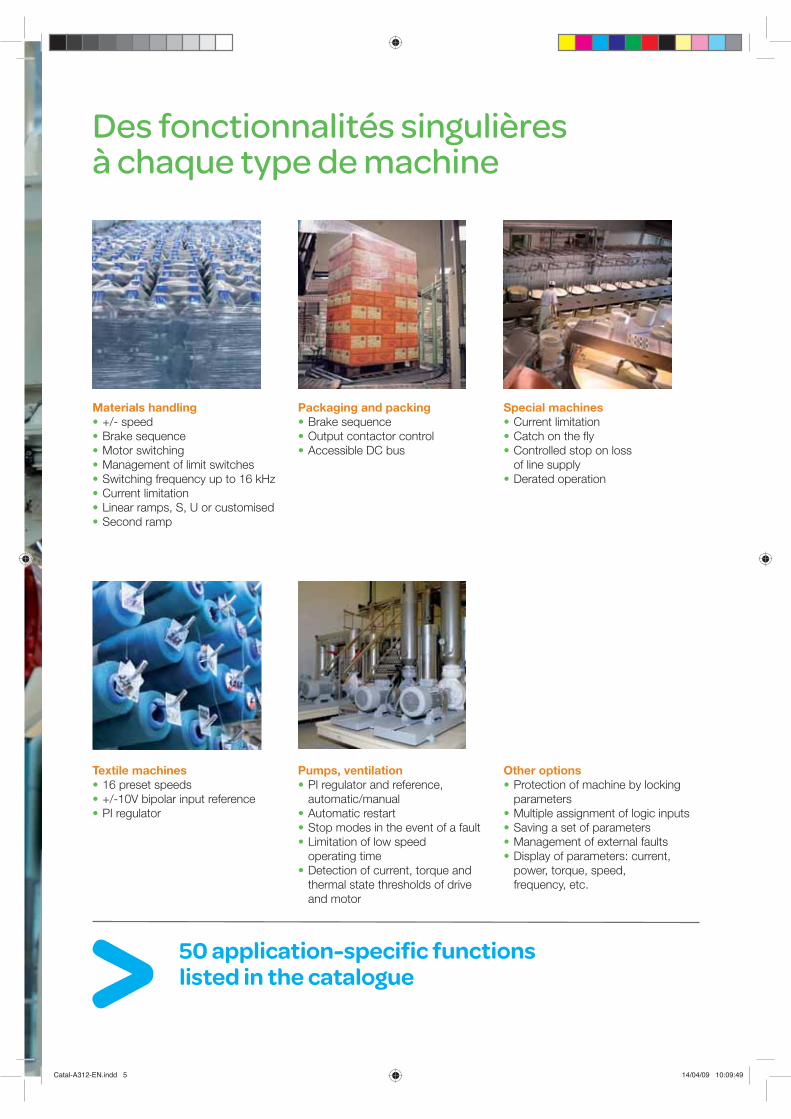
50 application-specific functions listed in the catalogue
Des fonctionnalités singulièresà chaque type de machine
Materials handling +/- speed Brake sequence Motor switching Management of limit switches Switching frequency up to 16 kHz Current limitation Linear ramps, S, U or customised Second ramp
Textile machines 16 preset speeds +/-10V bipolar input reference PI regulator
Packaging and packing Brake sequence Output contactor control Accessible DC bus
Pumps, ventilation PI regulator and reference, automatic/manual
Automatic restart Stop modes in the event of a fault Limitation of low speed operating time
Detection of current, torque and thermal state thresholds of drive and motor
Special machines Current limitation Catch on the fly Controlled stop on loss of line supply
Derated operation
Other options Protection of machine by locking parameters
Multiple assignment of logic inputs Saving a set of parameters Management of external faults Display of parameters: current, power, torque, speed, frequency, etc.
Catal-A312-EN.indd 5 14/04/09 10:09:49
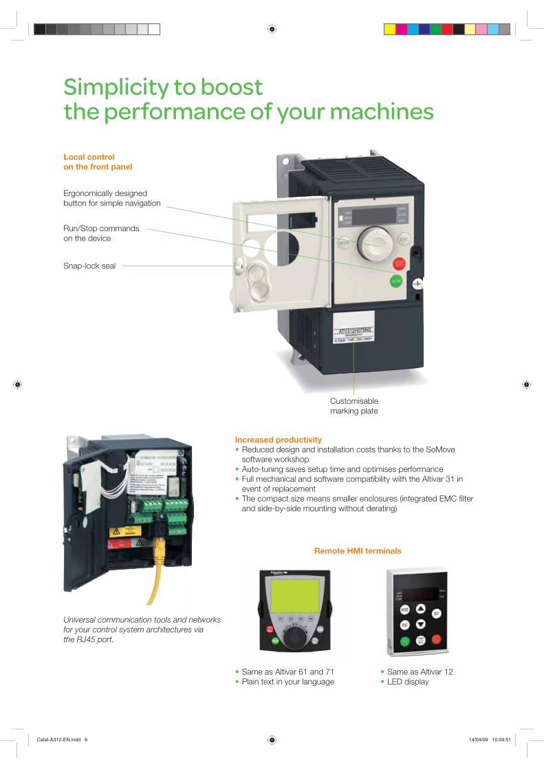
Simplicity to boost the performance of your machines
Increased productivity Reduced design and installation costs thanks to the SoMove software workshop
Auto-tuning saves setup time and optimises performance Full mechanical and software compatibility with the Altivar 31 in event of replacement
The compact size means smaller enclosures (integrated EMC filter and side-by-side mounting without derating)
Same as Altivar 61 and 71 Plain text in your language
Same as Altivar 12 LED display
Remote HMI terminals
Run/Stop commands on the device
Local control on the front panel
Ergonomically designed button for simple navigation
Snap-lock seal
Customisable marking plate
Universal communication tools and networks for your control system architectures via the RJ45 port.
Catal-A312-EN.indd 6 14/04/09 10:09:51

Communication with your control system architectures
Altivar 312 integrates transparently into your architectures and communicates with all control system products:• Modbus and CANopen are integrated as standard • Option cards: CANopen Daisy Chain, DeviceNet, Profibus DP• Gateways for Ethernet/Modbus and Fipio/Modbus
Altivar 312 variable speed drivesIntegrated
drive
CANopen
Stepper drive
BRS motors BSH motorElectronic
sensors
Servo drive
Remote I/O
PLC Human-machine dialogue
One connection, one software tool to programme the PLC and configure the drives
A global range with universal product references: Altivar 312 accompanies your machines wherever they travel in the world.
Catal-A312-EN.indd 7 14/04/09 10:09:54
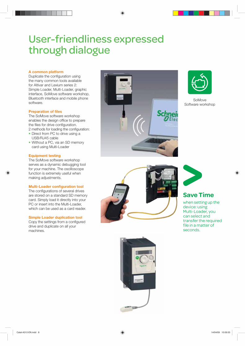
User-friendliness expressed through dialogue
A common platformDuplicate the configuration using the many common tools available for Altivar and Lexium series 2: Simple Loader, Multi-Loader, graphic interface, SoMove software workshop, Bluetooth interface and mobile phone software.
Preparation of filesThe SoMove software workshop enables the design office to prepare the files for drive configuration. 2 methods for loading the configuration: Direct from PC to drive using a USB/RJ45 cable
Without a PC, via an SD memory card using Multi-Loader
Equipment testingThe SoMove software workshop serves as a dynamic debugging tool for your machine. The oscilloscope function is extremely useful when making adjustments.
Multi-Loader configuration toolThe configurations of several drives are stored on a standard SD memory card. Simply load it directly into your PC or insert into the Multi-Loader, which can be used as a card reader.
Simple Loader duplication toolCopy the settings from a configured drive and duplicate on all your machines.
SoMove Software workshop
Save Timewhen setting up the device: using Multi-Loader, you can select and transfer the required file in a matter of seconds.
Catal-A312-EN.indd 8 14/04/09 10:09:55

Use your mobile to configure your Altivar 312
Efficiency with an all-in-one solution
Download and transfer configurations Drive adjustment and maintenance Send and receive configuration files locally or remotely in a matter
of seconds
Safety
and confidentiality
Monitor and adjust your machine from a secure location Bypass all the usual physical and security constraints to access your machines via the Bluetooth wireless connection.
You don’t even need to open the enclosure! Save changes or reinstall saved configurations whenever you want
Simplicity
and comfort
Work in comfort using Bluetooth wireless communication Take advantage of the user-friendly SoMove Mobile™
dialogue functions You know which menu you are in at any time Share configuration files via MMS or email
Altivar InnovationRemote configuration to update settings by mobile or PC via Bluetooth.
Catal-A312-EN.indd 9 14/04/09 10:09:55
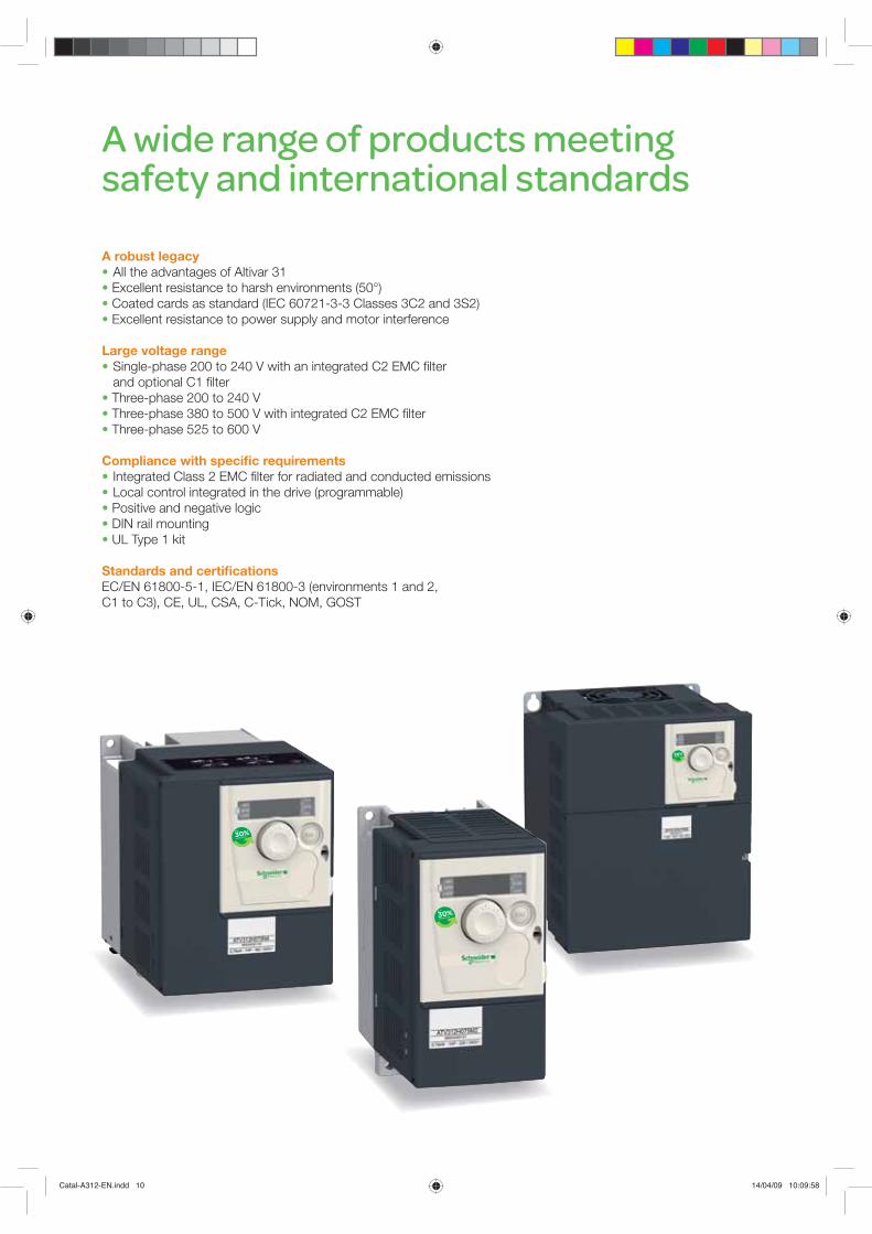
A wide range of products meeting safety and international standards
A robust legacy All the advantages of Altivar 31 Excellent resistance to harsh environments (50°) Coated cards as standard (IEC 60721-3-3 Classes 3C2 and 3S2) Excellent resistance to power supply and motor interference
Large voltage range Single-phase 200 to 240 V with an integrated C2 EMC filter
and optional C1 filter Three-phase 200 to 240 V Three-phase 380 to 500 V with integrated C2 EMC filter Three-phase 525 to 600 V
Compliance with specific requirements Integrated Class 2 EMC filter for radiated and conducted emissions Local control integrated in the drive (programmable) Positive and negative logic DIN rail mounting UL Type 1 kit
Standards and certificationsEC/EN 61800-5-1, IEC/EN 61800-3 (environments 1 and 2, C1 to C3), CE, UL, CSA, C-Tick, NOM, GOST
Catal-A312-EN.indd 10 14/04/09 10:09:58

2
1
3
4
5
6
7
8
9
10
1111
Selection guide . . . . . . . . . . . . . . . . . . . . . . . . . . . . . . . . . . . . . . . . . . . . page 12
Presentation . . . . . . . . . . . . . . . . . . . . . . . . . . . . . . . . . . . . . . . . . . . . . . . page 14
Altivar 312 variable speed drives
Characteristics . . . . . . . . . . . . . . . . . . . . . . . . . . . . . . . . . . . . . . . . . . . page 16References . . . . . . . . . . . . . . . . . . . . . . . . . . . . . . . . . . . . . . . . . . . . . . page 22
Options
Communication buses and networks . . . . . . . . . . . . . . . . . . . . . . . . . page 24Dialogue tools . . . . . . . . . . . . . . . . . . . . . . . . . . . . . . . . . . . . . . . . . . . page 30Configuration tools . . . . . . . . . . . . . . . . . . . . . . . . . . . . . . . . . . . . . . . page 31Braking resistors . . . . . . . . . . . . . . . . . . . . . . . . . . . . . . . . . . . . . . . . . page 34Line chokes . . . . . . . . . . . . . . . . . . . . . . . . . . . . . . . . . . . . . . . . . . . . . page 36Additional EMC input filters . . . . . . . . . . . . . . . . . . . . . . . . . . . . . . . . page 38Output filters and motor chokes . . . . . . . . . . . . . . . . . . . . . . . . . . . . . page 40
SoMove setup software . . . . . . . . . . . . . . . . . . . . . . . . . . . . . . . . . . . . . . page 32
Dimensions . . . . . . . . . . . . . . . . . . . . . . . . . . . . . . . . . . . . . . . . . . . . . . . page 42
Schemes . . . . . . . . . . . . . . . . . . . . . . . . . . . . . . . . . . . . . . . . . . . . . . . . . .page 48
Mounting and installation recommendations . . . . . . . . . . . . . . . . . . . . page 50
Motors starters . . . . . . . . . . . . . . . . . . . . . . . . . . . . . . . . . . . . . . . . . . . . . page 52
Functions . . . . . . . . . . . . . . . . . . . . . . . . . . . . . . . . . . . . . . . . . . . . . . . . . page 54
b
b
b
v
v
b
v
v
v
v
v
v
v
b
b
b
b
b
b
Variable speed drives Altivar 312
Contents
12
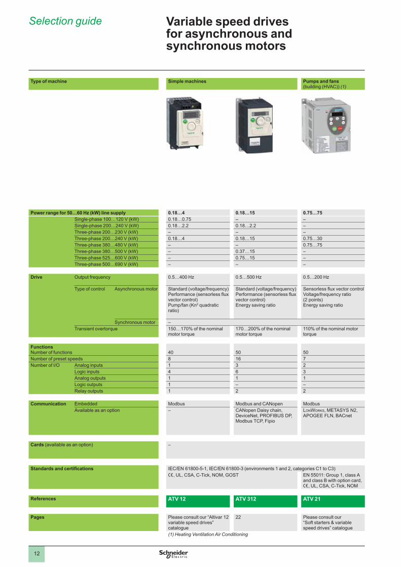
Variable speed drives for asynchronous and synchronous motors
Type of machine Simple machines Pumps and fans(building (HVAC)) (1)
Power range for 50…60 Hz (kW) line supply 0.18…4 0.18…15 0.75…75Single-phase 100…120 V (kW) 0.18…0.75 – –Single-phase 200…240 V (kW) 0.18…2.2 0.18…2.2 –Three-phase 200…230 V (kW) – – –Three-phase 200…240 V (kW) 0.18…4 0.18…15 0.75…30Three-phase 380…480 V (kW) – – 0.75…75Three-phase 380…500 V (kW) – 0.37…15 –Three-phase 525…600 V (kW) – 0.75…15 –Three-phase 500…690 V (kW) – – –
Drive Output frequency 0.5…400 Hz 0.5…500 Hz 0.5…200 Hz
Type of control Asynchronous motor Standard (voltage/frequency)Performance (sensorless flux vector control)Pump/fan (Kn2 quadratic ratio)
Standard (voltage/frequency)Performance (sensorless flux vector control)Energy saving ratio
Sensorless flux vector controlVoltage/frequency ratio (2 points)Energy saving ratio
Synchronous motor –Transient overtorque 150…170% of the nominal
motor torque170…200% of the nominal motor torque
110% of the nominal motor torque
FunctionsNumber of functions 40 50 50Number of preset speeds 8 16 7Number of I/O Analog inputs 1 3 2
Logic inputs 4 6 3Analog outputs 1 1 1Logic outputs 1 – –Relay outputs 1 2 2
Communication Embedded Modbus Modbus and CANopen ModbusAvailable as an option – CANopen Daisy chain,
DeviceNet, PROFIBUS DP, Modbus TCP, Fipio
LONWORKS, METASYS N2, APOGEE FLN, BACnet
Cards (available as an option) –
Standards and certifications IEC/EN 61800-5-1, IEC/EN 61800-3 (environments 1 and 2, categories C1 to C3)e, UL, CSA, C-Tick, NOM, GOST EN 55011: Group 1, class A
and class B with option card, e, UL, CSA, C-Tick, NOM
References ATV 12 ATV 312 ATV 21
Pages Please consult our “Altivar 12 variable speed drives” catalogue
22 Please consult our “Soft starters & variable speed drives” catalogue
(1) Heating Ventilation Air Conditioning
Selection guide
1
2
3
4
5
6
7
8
9
10

13
2
Pumps and fans(industrial)
Complex machines
0.37…800 0.37…630– –0.37…5.5 0.37…5.5– –0.75…90 0.37…750.75…630 0.75…500– –– –2.2…800 1.5…630
0.5…500 Hz across the entire range0.5…1000 Hz up to 37 kW at 200…240 V a and 380…480 V a
1…500 Hz across the entire range1…1600 Hz up to 37 kW at 200…240 V a and 380…480 V a
Sensorless flux vector controlVoltage/frequency ratio (2 or 5 points)Energy saving ratio
Flux vector control with or without sensorVoltage/frequency ratio (2 or 5 points)ENA System
Vector control without speed feedback Vector control with or without speed feedback120...130% of the nominal motor torque for 60 seconds 220% of the nominal motor torque for 2 seconds
170% for 60 seconds
> 100 > 1508 162…4 2…46…20 6…201…3 1…30…8 0…82…4 2…4
Modbus and CANopenModbus TCP, Fipio, Modbus/Uni-Telway, Modbus Plus, EtherNet/IP, DeviceNet, PROFIBUS DP, PROFIBUS DP V1, INTERBUS S, CC-Link, LONWORKS, METASYS N2, APOGEE FLN, BACnet
Modbus TCP, Fipio, Modbus/Uni-Telway, Modbus Plus, EtherNet/IP, DeviceNet, PROFIBUS DP, PROFIBUS DP V1, INTERBUS S, CC-Link
I/O extension cards, “Controller Inside” programmable card, multi-pump cards
Interface cards for incremental, resolver, SinCos, SinCos Hiperface®, EnDat® or SSI encoders, I/O extension cards, “Controller Inside” programmable card, overhead crane card
IEC/EN 61800-5-1, IEC/EN 61800-3 (environments 1 and 2, C1 to C3), IEC/EN 61000-4-2/4-3/4-4/4-5/4-6/4-11, e, UL, CSA, DNV, C-Tick, NOM, GOST
ATV 61 ATV 71
Please consult our “Soft starters & variable speed drives” and “ATV 61 variable speed drives” catalogues
Please consult our “Soft starters & variable speed drives” and “ATV 71 variable speed drives” catalogues
1
2
3
4
5
6
7
8
9
10

2
1
3
4
5
6
7
8
9
10
2
1
3
4
5
6
7
8
9
10
14
Presentation Variable speed drives Altivar 312
PresentationThe Altivar 312 drive is a frequency inverter for 200…600 V three-phase asynchronous motors from 0.18 to 15 kW. The Altivar 312 drive is robust, compact and easy to install. Its integrated functions are particularly suitable for the requirements of applications involving simple industrial machines.By taking account of constraints on product setup and use right from the design stage, we are able to offer a reliable, cost-effective solution to manufacturers of simple machines and installers.With its various communication cards that are available as options, the Altivar 312 drive integrates perfectly in the main control system architectures.
Examples of solutions provided:Numerous options for loading, editing and saving drive configurations using
various tools, such as the SoMove setup software, the SoMove Mobile software for mobile phones, remote display terminals and the Simple Loader and Multi-Loader configuration tools.
Adaptation to industrial communication buses and networks by simply replacing the drive control I/O card with one of the communication cards
User interface identical to the Altivar 12 range of variable speed drives, making setup easy and enabling those using it to adapt quickly.
b
b
b
ApplicationsThe Altivar 312 drive incorporates functions that are suitable for the most common applications, including:
Material handling (small conveyors, hoists, etc.)Packing and packaging machines (small bagging machines, labelling machines,
etc.)Special machines (mixers, kneaders, textile machines, etc.)Pumps, compressors, fans
bb
bb
FunctionsThe Altivar 312 drive has six logic inputs, three analog inputs, one logic/analog output and two relay outputs.The main functions available are as follows:
Motor and drive protectionLinear, S, U or customized acceleration and deceleration rampsLocal control of the speed reference using the navigation button+/- speed16 preset speedsPI regulator and references2-wire/3-wire controlBrake sequenceAutomatic catching a spinning load with speed detection and automatic restartFault configuration and stop type configurationSaving the configuration in the drive
Several functions can be assigned to one logic input.
bbbbbbbbbbb
An optimized offerThe Altivar 312 range of variable speed drives covers motor power ratings from 0.18 kW to 15 kW with four types of power supply:
200 V…240 V single-phase, 0.18 kW to 2.2 kW (ATV 312HpppM2)200 V…240 V three-phase, 0.18 kW to 15 kW (ATV 312HpppM3)380 V…500 V three-phase, 0.37 kW to 15 kW (ATV 312HpppN4)525 V…600 V three-phase, 0.75 kW to 15 kW (ATV 312HpppS6)
Several drives can be mounted side by side to save space.The Altivar 312 drive integrates the Modbus and CANopen communication protocols as standard. The protocols can be accessed via the RJ45 connector on the underside of the drive.In addition to the Modbus and CANopen protocols that can be accessed as standard, the Altivar 312 drive can be connected to the main industrial communication buses and networks by replacing the drive's control I/O card with one of the communication cards that are available as options: CANopen Daisy chain, DeviceNet and PROFIBUS DP. The Modbus TCP network and the Fipio bus are also accessible via dedicated gateways.See page 24.
bbbb
Characteristics:page 16
References:page 22
Dimensions:page 42
Schemes:page 48
Functions:page 54
ATV 312H037M3 ATV 312HD15N4
PF1
0274
4
Application: packaging
PF1
3150
129
Application: material handling
2
1
3
4
5
6
7
8
9
10
2
1
3
4
5
6
7
8
9
10
15
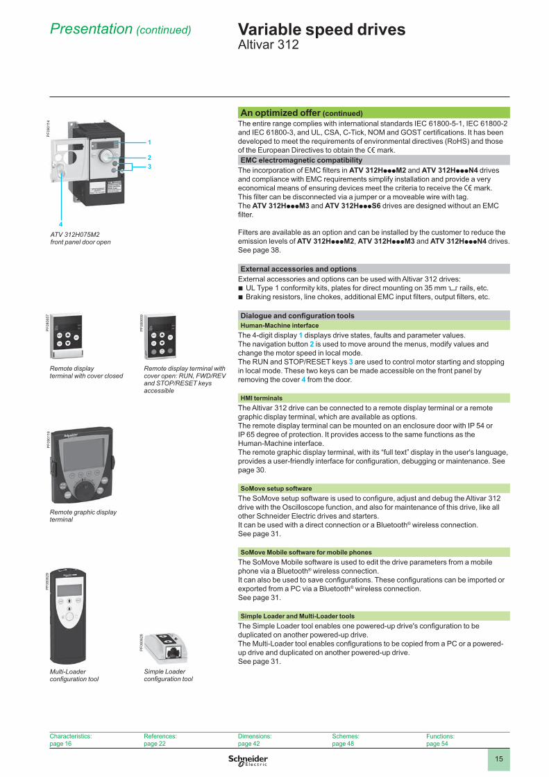
An optimized offer (continued)The entire range complies with international standards IEC 61800-5-1, IEC 61800-2 and IEC 61800-3, and UL, CSA, C-Tick, NOM and GOST certifications. It has been developed to meet the requirements of environmental directives (RoHS) and those of the European Directives to obtain the e mark.EMC electromagnetic compatibility
The incorporation of EMC filters in ATV 312HpppM2 and ATV 312HpppN4 drives and compliance with EMC requirements simplify installation and provide a very economical means of ensuring devices meet the criteria to receive the e mark. This filter can be disconnected via a jumper or a moveable wire with tag.The ATV 312HpppM3 and ATV 312HpppS6 drives are designed without an EMC filter.
Filters are available as an option and can be installed by the customer to reduce the emission levels of ATV 312HpppM2, ATV 312HpppM3 and ATV 312HpppN4 drives. See page 38.
External accessories and optionsExternal accessories and options can be used with Altivar 312 drives:
UL Type 1 conformity kits, plates for direct mounting on 35 mm 5 rails, etc.Braking resistors, line chokes, additional EMC input filters, output filters, etc.
bb
Dialogue and configuration toolsHuman-Machine interface
The 4-digit display 1 displays drive states, faults and parameter values.The navigation button 2 is used to move around the menus, modify values and change the motor speed in local mode.The RUN and STOP/RESET keys 3 are used to control motor starting and stopping in local mode. These two keys can be made accessible on the front panel by removing the cover 4 from the door.
HMI terminalsThe Altivar 312 drive can be connected to a remote display terminal or a remote graphic display terminal, which are available as options.The remote display terminal can be mounted on an enclosure door with IP 54 or IP 65 degree of protection. It provides access to the same functions as the Human-Machine interface.The remote graphic display terminal, with its “full text” display in the user's language, provides a user-friendly interface for configuration, debugging or maintenance. See page 30.
SoMove setup softwareThe SoMove setup software is used to configure, adjust and debug the Altivar 312 drive with the Oscilloscope function, and also for maintenance of this drive, like all other Schneider Electric drives and starters.It can be used with a direct connection or a Bluetooth® wireless connection.See page 31.
SoMove Mobile software for mobile phonesThe SoMove Mobile software is used to edit the drive parameters from a mobile phone via a Bluetooth® wireless connection.It can also be used to save configurations. These configurations can be imported or exported from a PC via a Bluetooth® wireless connection.See page 31.
Simple Loader and Multi-Loader toolsThe Simple Loader tool enables one powered-up drive's configuration to be duplicated on another powered-up drive.The Multi-Loader tool enables configurations to be copied from a PC or a powered-up drive and duplicated on another powered-up drive.See page 31.
Characteristics:page 16
References:page 22
Dimensions:page 42
Schemes:page 48
Functions:page 54
Variable speed drives Altivar 312
Presentation (continued)
Remote display terminal with cover open: RUN, FWD/REV and STOP/RESET keys accessible
PF0
8065
9
PF0
9011
6
Remote graphic display terminal
Multi-Loader configuration tool
PF0
8062
9
Remote display terminal with cover closed
PF0
8065
7
ATV 312H075M2 front panel door open
2
1
3
PF0
9011
4
4
Simple Loader configuration tool
PF0
8062
8
2
1
3
4
5
6
7
8
9
10
2
1
3
4
5
6
7
8
9
10
16
Characteristics Variable speed drives Altivar 312
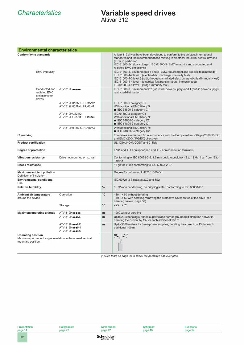
Environmental characteristicsConformity to standards Altivar 312 drives have been developed to conform to the strictest international
standards and the recommendations relating to electrical industrial control devices (IEC), in particular:IEC 61800-5-1 (low voltage), IEC 61800-3 (EMC immunity and conducted and radiated EMC emissions).
EMC immunity IEC 61800-3, Environments 1 and 2 (EMC requirement and specific test methods) IEC 61000-4-2 level 3 (electrostatic discharge immunity test)IEC 61000-4-3 level 3 (radio-frequency radiated electromagnetic field immunity test)IEC 61000-4-4 level 4 (electrical fast transient/burst immunity test)IEC 61000-4-5 level 3 (surge immunity test)
Conducted and radiated EMC emissions for drives
ATV 312Hppppp IEC 61800-3, Environments: 2 (industrial power supply) and 1 (public power supply), restricted distribution
ATV 312H018M2...HU15M2 ATV 312H037N4...HU40N4
IEC 61800-3 category C2With additional EMC filter (1):
IEC 61800-3 category C1b
ATV 312HU22M2, ATV 312HU55N4...HD15N4
IEC 61800-3 category C3With additional EMC filter (1):
IEC 61800-3 category C2IEC 61800-3 category C1
bb
ATV 312H018M3...HD15M3 With additional EMC filter (1):IEC 61800-3 category C2b
e marking The drives are marked e in accordance with the European low voltage (2006/95/EC) and EMC (2004/108/EC) directives
Product certification UL, CSA, NOM, GOST and C-Tick
Degree of protection IP 31 and IP 41 on upper part and IP 21 on connection terminals
Vibration resistance Drive not mounted on 5 rail Conforming to IEC 60068-2-6: 1.5 mm peak to peak from 3 to 13 Hz, 1 gn from 13 to 150 Hz
Shock resistance 15 gn for 11 ms conforming to IEC 60068-2-27
Maximum ambient pollutionDefinition of insulation
Degree 2 conforming to IEC 61800-5-1
Environmental conditionsUse
IEC 60721-3-3 classes 3C2 and 3S2
Relative humidity % 5…95 non condensing, no dripping water, conforming to IEC 60068-2-3
Ambient air temperature around the device
Operation °C - 10…+ 50 without derating- 10…+ 60 with derating removing the protective cover on top of the drive (see derating curves, page 50)
Storage °C - 25…+ 70
Maximum operating altitude ATV 312Hppppp m 1000 without deratingATV 312HpppM2 m Up to 2000 for single-phase supplies and corner grounded distribution networks,
derating the current by 1% for each additional 100 mATV 312HpppM3ATV 312HpppN4ATV 312HpppS6
m Up to 3000 metres for three-phase supplies, derating the current by 1% for each additional 100 m
Operating position Maximum permanent angle in relation to the normal vertical mounting position
(1) See table on page 39 to check the permitted cable lengths.
Presentation:page 14
References:page 22
Dimensions:page 42
Schemes:page 48
Functions:page 54
2
1
3
4
5
6
7
8
9
10
2
1
3
4
5
6
7
8
9
10
17
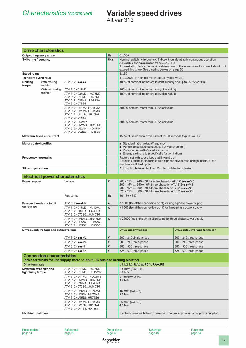
Characteristics (continued) Variable speed drives Altivar 312
Drive characteristicsOutput frequency range Hz 0…500Switching frequency kHz Nominal switching frequency: 4 kHz without derating in continuous operation.
Adjustable during operation from 2…16 kHzAbove 4 kHz, derate the nominal drive current. The nominal motor current should not exceed this value. See derating curves on page 50
Speed range 1…50Transient overtorque 170...200% of nominal motor torque (typical value)Braking torque
With braking resistor
ATV 312Hppppp 100% of nominal motor torque continuously and up to 150% for 60 s
Without braking resistor
ATV 312H018M2 150% of nominal motor torque (typical value)ATV 312H037M2…H075M2ATV 312H018M3…H075M3ATV 312H037N4…H075N4ATV 312H075S6
100% of nominal motor torque (typical value)
ATV 312HU11M2, HU15M2ATV 312HU11M3, HU15M3ATV 312HU11N4, HU15N4ATV 312HU15S6
50% of nominal motor torque (typical value)
ATV 312HU22M2ATV 312HU22M3…HD15M3 ATV 312HU22N4…HD15N4ATV 312HU22S6…HD15S6
30% of nominal motor torque (typical value)
Maximum transient current 150% of the nominal drive current for 60 seconds (typical value)
Motor control profiles Standard ratio (voltage/frequency)Performance ratio (sensorless flux vector control)Pump/fan ratio (Kn2 quadratic ratio) Energy saving ratio (specifically for ventilation)
bbbb
Frequency loop gains Factory-set with speed loop stability and gainPossible options for machines with high resistive torque or high inertia, or for machines with fast cycles
Slip compensation Automatic whatever the load. Can be inhibited or adjusted
Electrical power characteristicsPower supply Voltage V 200 - 15% … 240 + 10% single-phase for ATV 312ppppM2
200 - 15% … 240 + 10% three-phase for ATV 312ppppM3380 - 15% … 500 + 10% three-phase for ATV 312ppppN4525 - 15% … 600 + 10% three-phase for ATV 312ppppS6
Frequency Hz 50…60 + 5%
Prospective short-circuit current Isc
ATV 312ppppM2 A y 1000 (Isc at the connection point) for single-phase power supplyATV 312H018M3…HU40M3ATV 312H037N4…HU40N4ATV 312H075S6…HU40S6
A y 5000 (Isc at the connection point) for three-phase power supply
ATV 312HU55M3…HD15M3ATV 312HU55N4…HD15N4ATV 312HU55S6…HD15S6
A y 22000 (Isc at the connection point) for three-phase power supply
Drive supply voltage and output voltage Drive supply voltage Drive output voltage for motor
ATV 312HpppM2 V 200…240 single-phase 200…240 three-phaseATV 312HpppM3 V 200…240 three-phase 200…240 three-phaseATV 312HpppN4 V 380…500 three-phase 380…500 three-phaseATV 312HpppS6 V 525…600 three-phase 525…600 three-phase
Connection characteristics (drive terminals for line supply, motor output, DC bus and braking resistor)Drive terminals L1, L2, L3, U, V, W, PC/–, PA/+, PB
Maximum wire size and tightening torque
ATV 312H018M2…H075M2ATV 312H018M3…HU15M3
2.5 mm2 (AWG 14)0.8 Nm
ATV 312HU11M2…HU22M2ATV 312HU22M3…HU40M3ATV 312H037N4…HU40N4ATV 312H075S6…HU40S6
5 mm2 (AWG 10)1.2 Nm
ATV 312HU55M3, HU75M3ATV 312HU55N4, HU75N4ATV 312HU55S6, HU75S6
16 mm2 (AWG 6)2.5 Nm
ATV 312HD11M3, HD15M3ATV 312HD11N4, HD15N4ATV 312HD11S6, HD15S6
25 mm2 (AWG 3)4.5 Nm
Electrical isolation Electrical isolation between power and control (inputs, outputs, power supplies)
Presentation:page 14
References:page 22
Dimensions:page 42
Schemes:page 48
Functions:page 54

2
1
3
4
5
6
7
8
9
10
2
1
3
4
5
6
7
8
9
10
18
Characteristics (continued) Variable speed drives Altivar 312
Electrical control characteristicsAvailable internal supplies
Protected against short-circuits and overloads:One 10 V c (0/+ 8%) supply for the reference potentiometer (2.2 to 10 kΩ),
maximum current 10 mAOne 24 V c supply (min. 19 V, max. 30 V) for the control logic inputs, maximum
current 100 mA
b
b
Analog inputs Sampling time < 8 ms Resolution: 10 bitsAccuracy: ± 4.3%Linearity: ± 0.2% of the maximum scale valueUse:
100 m maximum with shielded cable25 m maximum with unshielded cable
bb
Al1 One 0...10 V c analog voltage input , impedance 30 kΩ, maximum safe voltage 30 V
Al2 One ± 10 V bipolar voltage analog input, impedance 30 kΩ, maximum safe voltage 30 V
Al3 One X-Y mA analog current input, X and Y programmable from 0 to 20 mA, with impedance 250 Ω
Analog voltage outputs or analog current outputs configurable as logic outputs
2 analog outputs:1 analog voltage output (AOV)1 analog current output (AOC) configurable as a logic output.
These 2 analog outputs cannot be used at the same time
bb
AOV 0...10 V c analog voltage output, min. load impedance 470 Ω 8-bit resolution, accuracy ± 1%, linearity ± 0.2% of the maximum scale value
AOC 0…20 mA analog current output, max. load impedance 800 Ω 8-bit resolution, accuracy ± 1%, linearity ± 0.2%The AOC analog output can be configured as a 24 V logic output, max. 20 mA, min. load impedance 1.2 kΩRefresh time < 8 ms
Relay outputs R1A, R1B, R1C 1 relay logic output, one N/C contact and one N/O contact with common pointMinimum switching capacity: 10 mA for 5 V cMaximum switching capacity:
On resistive load (cos ϕ = 1 and L/R = 0 ms): 5 A for 250 V a or 30 V cOn inductive load (cos ϕ = 0.4 and L/R = 7 ms): 2 A for 250 V a or 30 V c
Sampling time < 8 msSwitching: 100,000 operations
bb
R2A, R2B 1 relay logic output, one N/C contact, contact open on fault.Minimum switching capacity: 10 mA for 5 V cMaximum switching capacity:
On resistive load (cos ϕ = 1 and L/R = 0 ms): 5 A for 250 V a or 30 V cOn inductive load (cos ϕ = 0.4 and L/R = 7 ms): 2 A for 250 V a or 30 V c
Sampling time < 8 msSwitching: 100,000 operations
bb
LI logic inputs LI1…LI6 6 programmable logic inputs, compatible with PLC level 1, standard IEC/EN 61131-2Impedance 3.5 kΩ24 V c internal or 24 V c external power supply (min. 19 V, max. 30 V)Max. current: 100 mASampling time < 4 msMultiple assignment makes it possible to configure several functions on one input (example: LI1 assigned to forward and preset speed 2, LI3 assigned to reverse and preset speed 3)
Positive logic (Source) State 0 if < 5 V or logic input not wiredState 1 if > 11 V
Negative logic (Sink) State 0 if > 19 V or logic input not wiredState 1 if < 13 V
CLI position Connection to PLC output (see diagram on page 48)
Maximum I/O wire size and tightening torque
2.5 mm2 (AWG 14)0.6 Nm
Presentation:page 14
References:page 22
Dimensions:page 42
Schemes:page 48
Functions:page 54

2
1
3
4
5
6
7
8
9
10
2
1
3
4
5
6
7
8
9
10
19
Electrical control characteristics (continued)Acceleration and deceleration ramps Ramp profiles:
Linear, can be adjusted separately from 0.1 to 999.9 sS, U or customized
Automatic adaptation of deceleration ramp time if braking capacities exceeded, possible inhibition of this adaptation (use of a braking resistor)
bb
Braking to a standstill By DC injection:By a command on a logic input (LI1 to LI6)Automatically as soon as the estimated output frequency drops to < 0.5 Hz, period
adjustable from 0 to 30 s or continuous, current adjustable from 0 to 1.2 In
bb
Main drive protection and safety features Thermal protection against overheatingProtection against short-circuits between motor phasesInput phase loss protection, for three-phase supplyProtection against motor phase breaksOvercurrent protection between motor output phases and earthLine supply overvoltage and undervoltage safety features
Motor protection(see page 67)
Thermal protection integrated in the drive by continuous calculation of the l2t
Dielectric strength
Between earth and power terminals
ATV 312HpppM2ATV 312HpppM3
2040 V c
ATV 312HpppN4 2410 V c
ATV 312HpppS6 2550 V c
Between control and power terminals
ATV 312HpppM2ATV 312HpppM3
2880 V a
ATV 312HpppN4 3400 V a
ATV 312HpppS6 3600 V a
Signalling Display coded by one 4-digit display (messages, values) and 5 status LEDs (current mode, CANopen bus)
Frequency resolution
Display units Hz 0.1
Analog inputs Hz Resolution = ((high speed - low speed)/1024)Min. value = 0.1
Time constant on a change of reference ms 5
Characteristics (continued) Variable speed drives Altivar 312
Presentation:page 14
References:page 22
Dimensions:page 42
Schemes:page 48
Functions:page 54

2
1
3
4
5
6
7
8
9
10
2
1
3
4
5
6
7
8
9
10
20
Communication port characteristicsAvailable protocols Modbus and CANopen protocols integrated in the drive.
Both these protocols can be accessed via a single RJ45 connector on the underside of the drive.
Modbus protocolStructure Connector RJ45
Physical interface RS 485Transmission mode RTUTransmission speed Configurable via the Human-Machine interface, remote display terminals or SoMove
setup software: 4800, 9600 or 19200 bps
Number of subscribers 31Address 1 to 247, configurable via the Human-Machine interface, remote display terminals or
SoMove setup softwareServices Functional profiles CiA 402
Messaging Read Holding Registers (03)Write Single Register (06) Write Multiple Registers (16)Read Device Identification (43)
Communication monitoring Configurable
CANopen protocolStructure Connector RJ45
Network management SlaveTransmission speed Configurable via the Human-Machine interface, remote display terminals or SoMove
setup software: 10, 20, 50, 125, 250, 500 kbps or 1 MbpsNumber of subscribers 127Address (Node ID) 1 to 127, configurable via the Human-Machine interface, remote display terminals or
SoMove setup softwareServices Number of PDOs
(Process Data Objects)2 PDOs:
PDO 1: cannot be configuredPDO 6: can be configured
bb
PDO modes PDO 1: asynchronousPDO 6: asynchronous, Sync, cyclic asynchronous
Number of SDOs (Service Data Objects)
1 receive SDO and 1 transmit SDO
Functional profiles CiA 402Communication monitoring Node guarding and Heartbeat
Diagnostics Using LEDs On Human-Machine interfaceDescription file An eds file is available on our website www.schneider-electric.com or the “Description
of the Motion & Drives offer” DVD-ROM
Characteristics (continued) Variable speed drives Altivar 312
Presentation:page 14
References:page 22
Dimensions:page 42
Schemes:page 48
Functions:page 54

2
1
3
4
5
6
7
8
9
10
2
1
3
4
5
6
7
8
9
10
21
Characteristics (continued), special uses
Variable speed drives Altivar 312
Torque characteristics (typical curves) The curves opposite define the available continuous torque and transient overtorque for both force-cooled and self-cooled motors. The only difference is in the ability of the motor to provide a high continuous torque at less than half the nominal speed.
Self-cooled motor: continuous useful torque (1)Force-cooled motor: continuous useful torqueTransient overtorque 1.7 to 2 TnTorque in overspeed at constant power (2)
Special usesUse with a motor with a different power rating to that of the drive
The device can power any motor which has a lower rating than that for which the drive was designed.For motor ratings slightly higher than that of the drive, check that the current taken does not exceed the continuous output current of the drive.
Testing on a low power motor or without a motorIn a testing or maintenance environment the drive can be checked without having to switch to a motor with the same rating as the drive (particularly useful in the case of high power drives). This use requires deactivation of motor phase loss detection.
Use of motors in parallelThe drive rating must be greater than or equal to the sum of the currents and powers of the motors to be controlled.In this case, it is necessary to provide external thermal protection for each motor using probes or thermal overload relays.If three or more motors are connected in parallel, it is advisable to install a motor choke between the drive and the motors.See page 40.
Motor switching at the drive output Switching can be carried out with the drive locked or unlocked. In the case of switching on-the-fly (drive unlocked), the motor is controlled and accelerated until it reaches the reference speed smoothly following the acceleration ramp.This use requires configuration of automatic catching a spinning load (“catch on the fly”) and activation of the function which manages the presence of an output contactor.
Note: Depending on the drive rating, downstream ferrite suppressors may be required between the drive and the output contactor (see page 40).
Typical applications: loss of safety circuit at drive output, bypass function, switching of motors connected in parallel.
Recommendations for use: synchronize control of the output contactor with that of a freewheel stop request from the drive on a logic input.
(1) For power ratings y 250 W, less derating is required (20% instead of 50% at very low frequencies).
(2) The nominal motor frequency and the maximum output frequency can be adjusted from 40 to 500 Hz. The mechanical overspeed characteristics of the selected motor must be checked with the manufacturer.
1 2 3 4
1,71,75
1,50
1,25
2,25
1
2
0,95
0,75
0,50
0,25
00 25/30 50/60 75/90 100/120
4
Hz
1
12 2
3
Tn
1,71,75
1,50
1,25
2,25
1
2
0,95
0,75
0,50
0,25
00 25/30 50/60 75/90 100/120
4
Hz
1
12 2
3
Tn
N
t1 > 500 ms
KM1 0
1
t2
t
t
KM1: contactort1: KM1 opening time (motor freewheeling)t2: acceleration with ramp N: speedExample of loss of output contactor
MKM1
Altivar 312
N
t1 > 500 ms
KM1 0
1
t2
t
t
KM1: contactort1: KM1 opening time (motor freewheeling)t2: acceleration with ramp N: speedExample of loss of output contactor
MKM1
Altivar 312
Presentation:page 14
References:page 22
Dimensions:page 42
Schemes:page 48
Functions:page 54
2
1
3
4
5
6
7
8
9
10
22
References Variable speed drives Altivar 312
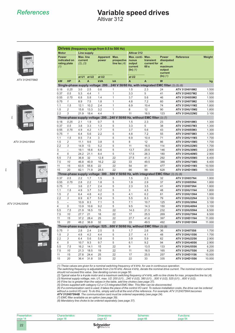
Drives (frequency range from 0.5 to 500 Hz)Motor Line supply Altivar 312Power indicated on rating plate (1)
Max. line current (2), (3)
Apparent power
Max. prospective line Isc (4)
Max. conti-nuous output current (In) (1)
Max. transient current for 60 s
Power dissipated at maximum output current (In) (1)
Reference Weight
at U1 at U2 at U2 at U2kW HP A A kVA kA A A W kgSingle-phase supply voltage: 200…240 V 50/60 Hz, with integrated EMC filter (3) (5) (6)
0.18 0.25 3.0 2.5 0.6 1 1.5 2.3 24 ATV 312H018M2 1.5000.37 0.5 5.3 4.4 1 1 3.3 5 41 ATV 312H037M2 1.5000.55 0.75 6.8 5.8 1.4 1 3.7 5.6 46 ATV 312H055M2 1.5000.75 1 8.9 7.5 1.8 1 4.8 7.2 60 ATV 312H075M2 1.5001.1 1.5 12.1 10.2 2.4 1 6.9 10.4 74 ATV 312HU11M2 1.8001.5 2 15.8 13.3 3.2 1 8 12 90 ATV 312HU15M2 1.8002.2 3 21.9 18.4 4.4 1 11 16.5 123 ATV 312HU22M2 3.100Three-phase supply voltage: 200…240 V 50/60 Hz, without EMC filter (3) (7)
0.18 0.25 2.1 1.9 0.7 5 1.5 2.3 23 ATV 312H018M3 1.3000.37 0.5 3.8 3.3 1.3 5 3.3 5 38 ATV 312H037M3 1.3000.55 0.75 4.9 4.2 1.7 5 3.7 5.6 43 ATV 312H055M3 1.3000.75 1 6.4 5.6 2.2 5 4.8 7.2 55 ATV 312H075M3 1.3001.1 1.5 8.5 7.4 3 5 6.9 10.4 71 ATV 312HU11M3 1.7001.5 2 11.1 9.6 3.8 5 8 12 86 ATV 312HU15M3 1.7002.2 3 14.9 13 5.2 5 11 16.5 114 ATV 312HU22M3 1.7003 – 19.1 16.6 6.6 5 13.7 20.6 146 ATV 312HU30M3 2.9004 5 24.2 21.1 8.4 5 17.5 26.3 180 ATV 312HU40M3 2.9005.5 7.5 36.8 32 12.8 22 27.5 41.3 292 ATV 312HU55M3 6.4007.5 10 46.8 40.9 16.2 22 33 49.5 388 ATV 312HU75M3 6.40011 15 63.5 55.6 22 22 54 81 477 ATV 312HD11M3 10.50015 20 82.1 71.9 28.5 22 66 99 628 ATV 312HD15M3 10.500Three-phase supply voltage: 380…500 V 50/60 Hz, with integrated EMC filter (3) (5) (6)
0.37 0.5 2.2 1.7 1.5 5 1.5 2.3 32 ATV 312H037N4 1.8000.55 0.75 2.8 2.2 1.8 5 1.9 2.9 37 ATV 312H055N4 1.8000.75 1 3.6 2.7 2.4 5 2.3 3.5 41 ATV 312H075N4 1.8001.1 1.5 4.9 3.7 3.2 5 3 4.5 48 ATV 312HU11N4 1.8001.5 2 6.4 4.8 4.2 5 4.1 6.2 61 ATV 312HU15N4 1.8002.2 3 8.9 6.7 5.9 5 5.5 8.3 79 ATV 312HU22N4 3.1003 – 10.9 8.3 7.1 5 7.1 10.7 125 ATV 312HU30N4 3.1004 5 13.9 10.6 9.2 5 9.5 14.3 150 ATV 312HU40N4 3.1005.5 7.5 21.9 16.5 15 22 14.3 21.5 232 ATV 312HU55N4 6.5007.5 10 27.7 21 18 22 17 25.5 269 ATV 312HU75N4 6.50011 15 37.2 28.4 25 22 27.7 41.6 397 ATV 312HD11N4 11.00015 20 48.2 36.8 32 22 33 49.5 492 ATV 312HD15N4 11.000Three-phase supply voltage: 525…600 V 50/60 Hz, without EMC filter (3) (8)
0.75 1 2.8 2.4 2.5 5 1.7 2.6 36 ATV 312H075S6 1.7001.5 2 4.8 4.2 4.4 5 2.7 4.1 48 ATV 312HU15S6 1.7002.2 3 6.4 5.6 5.8 5 3.9 5.9 62 ATV 312HU22S6 2.9004 5 10.7 9.3 9.7 5 6.1 9.2 94 ATV 312HU40S6 2.9005.5 7.5 16.2 14.1 15 22 9 13.5 133 ATV 312HU55S6 6.2007.5 10 21.3 18.5 19 22 11 16.5 165 ATV 312HU75S6 6.20011 15 27.8 24.4 25 22 17 25.5 257 ATV 312HD11S6 10.00015 20 36.4 31.8 33 22 22 33 335 ATV 312HD15S6 10.000
(1) These values are given for a nominal switching frequency of 4 kHz, for use in continuous operation. The switching frequency is adjustable from 2 to16 kHz. Above 4 kHz, derate the nominal drive current. The nominal motor current should not exceed this value. See derating curves on page 50.(2) Typical value for a 4-pole motor and a maximum switching frequency of 4 kHz, with no line choke for max. prospective line Isc (4).(3) Nominal supply voltage, min. U1, max. U2: 200 (U1)…240 V (U2), 380 (U1)…500 V (U2), 525 (U1)…600 V (U2).(4) If line Isc is greater than the values in the table, add line chokes (see page 37).(5) Drives supplied with category C2 or C3 integrated EMC filter. This filter can be disconnected.(6) If a communication card is used, it takes the place of the control I/O card. To reduce installation costs, the drive can be ordered without a control I/O card. To do this, simply add a B at the end of the reference. For example: ATV 312H075N4 becomes ATV 312H075N4B. The communication card must be ordered separately (see page 24).(7) EMC filter available as an option (see page 39).(8) Mandatory line choke to be ordered separately (see page 37).
Presentation:page 14
Characteristics:page 16
Dimensions:page 42
Schemes:page 48
Functions:page 54
ATV 312H075M2
ATV 312HU15N4
PF0
ATV 312HU30N4
PF0

2
1
3
4
5
6
7
8
9
10
2
1
3
4
5
6
7
8
9
10
23
References (continued) Variable speed drives Altivar 312Accessories, documentation, replacement parts
AccessoriesDescription For drives Reference Weight
kgPlates for mounting on 5 rail, width 35 mm
ATV 312H018M2…H075M2ATV 312H018M3…H075M3
VW3 A9 804 0.290
ATV 312HU11M2, HU15M2ATV 312HU11M3…HU22M3ATV 312H037N4…HU15N4ATV 312H075S6, HU15S6
VW3 A9 805 0.385
UL Type 1 conformity kits Mechanical device for fixing to the lower part of the drive.For direct connection of cables to the drive via tubes or cable glands
ATV 312H018M2…H075M2 VW3 A31812 0.400ATV 312H018M3…H075M3 VW3 A31811 0.400ATV 312HU11M3, HU15M3 VW3 A31813 0.400ATV 312HU11M2, HU15M2ATV 312HU22M3ATV 312H037N4…HU15N4 ATV 312H075S6, HU15S6
VW3 A31814 0.500
ATV 312HU22M2ATV 312HU30M3, HU40M3ATV 312HU22N4…HU40N4ATV 312HU22S6, HU40S6
VW3 A31815 0.500
ATV 312HU55M3, HU75M3 ATV 312HU55N4, HU75N4 ATV 312HU55S6, HU75S6
VW3 A31816 0.900
ATV 312HD11M3, HD15M3ATV 312HD11N4, HD15N4ATV 312HD11S6, HD15S6
VW3 A31817 1.200
DocumentationDescription Reference Weight
kg“Description of the Motion & Drives offer” DVD-ROM Comprises (1):
Technical documentation (programming manuals, installation manuals, quick reference guides)
SoMove lite setup softwareCataloguesBrochures
b
bbb
VW3 A8 200 0.100
Replacement partsDescription For drives Reference Weight
kgATV 312 control I/O card ATV 312Hppppp VW3 A312 01 0.200
Fans ATV 312HU11M2, HU15M2ATV 312HU11M3, HU22M3ATV 312H037N4, HU15N4ATV 312H075S6, HU15S6
VZ3 V3 101 0.200
ATV 312HU22M2ATV 312HU30M3, HU40M3ATV 312HU22N4, HU40N4ATV 312HU22S6, HU40S6
VZ3 V3 102 0.200
ATV 312HU55M3, HU75M3ATV 312HU55N4, HU75N4ATV 312HU55S6, HU75S6
VZ3 V3 103 0.200
ATV 312HD11M3, HD15M3ATV 312HD11N4, HD15N4ATV 312HD11S6, HD15S6
VZ3 V3 104 0.300
(1) The contents of this DVD-ROM are also available on our website www.schneider-electric.com.
Presentation:page 14
Characteristics:page 16
Dimensions:pages 42 and 44
Schemes:page 48
Functions:page 54
VW3 A9 804
PF0
8067
0
VZ3 V3 101
PF0
8064
7

24
Presentation Variable speed drivesAltivar 312Communication buses and networks
PresentationThe Altivar 312 drive is designed to meet the configuration requirements found in the main industrial communication installations.It includes the Modbus and CANopen communication protocols as standard.It can also be connected to other industrial communication buses and networks using one of the communication cards or modules that are available as options.
Standard configurationThe Altivar 312 drive is equipped with a control I/O card 1 which integrates:
I/O terminals, comprising:Six logic inputs: LI1 to LI6Three analog inputs: AI1 to AI3Two analog outputs: AOV and AOC (2)Two relay outputs: R1 and R2A Modbus/CANopen communication port, that is accessed on an RJ45 connector
The Modbus/CANopen communication port is specifically for controlling the drive via a PLC or another type of controller.It is also used for connecting dialogue and configuration tools:
Remote display terminal Remote graphic display terminal SoMove setup software SoMove Mobile software for mobile phones Simple Loader and Multi-Loader configuration tools
bvvvvb
bbbbb
Communication cards for industrial applicationsSeveral communication cards for industrial applications 2 are available as options.These cards are used in place of the drive's control I/O card 1 (1)The following communication cards are available:
CANopen Daisy chain card (optimized solution for daisy chain connection to CANopen machine bus, see page 28)
DeviceNet cardPROFIBUS DP card
b
bb
Communication modulesThe Altivar 312 drive can be connected to other communication buses and networks via modules that are available as options:
Modbus TCP network via the Ethernet/Modbus bridgeFipio bus via the Fipio/Modbus gateway
bb(1) To reduce installation costs when replacing the control I/O card 1 with a communication card 2, ATV 312HpppM2 and ATV 312HpppN4 drives can be ordered without a control I/O card. See page 22.(2) These two outputs cannot be used at the same time.
Functions: page 25
Characteristics:page 25
References:page 26
Example of configuration on Modbus serial link
Modicon M340
ATV 312 ATV 312 ATV 312
ATV 61
Magelis XBT
Modbus serial link
1
2
Example of installation of a communication card (1)
Modicon M340
Sensors
ATV 312XCC encoder
ATV 61
Magelis XBT
CANopen machine bus
I/O
Example of configuration on CANopen machine bus

25
Functions, characteristics
Variable speed drivesAltivar 312Communication buses and networks
FunctionsAll the functions of the Altivar 312 drive can be accessed via the communication buses and networks:
ControlMonitoringAdjustmentConfiguration
The speed control and reference may come from different control sources:Logic input or analog I/O terminalsCommunication bus or networkRemote display terminal
The advanced functions of the Altivar 312 drive can be used to manage switching of these control sources according to the requirements of the application.The assignment of the communication periodic I/O data can be selected using the network configuration software.The Altivar 312 drive is controlled using the CiA 402 native profile.
Communication is monitored according to criteria specific to each protocol. Regardless of protocol type, the reaction of the drive to a communication fault can be configured as follows:
Freewheel stop, stop on ramp, fast stop or braked stopMaintain the last command receivedFallback position at a predefined speedIgnore the fault
bbbb
bbb
bbbb
Characteristics of the CANopen Daisy chain card VW3 A312 08 (1)Structure Connector 4 connectors:
1 removable screw terminal block:3 logic inputs: LI1 to LI32 analog inputs: AI2 and AI31 relay output: R22 RJ45 connectors for daisy-chain connection to the CANopen machine bus1 RJ45 connector for connection to the Modbus serial link
bvvvbb
(1) The other characteristics of the CANopen Daisy chain card are identical to those of the drive's CANopen protocol. See page 20.
Characteristics of the DeviceNet card VW3 A312 09Structure Connector 3 connectors:
1 removable screw terminal block:3 logic inputs: LI1 to LI32 analog inputs: AI2 and AI31 relay output: R2.1 five-way screw connector, 5.08 pitch, for connection to the DeviceNet network1 RJ45 connector for connection to the Modbus serial link
bvvvbb
Transmission speed 125 kbps, 250 kbps or 500 kbps, configurable using switches on the cardAddress 1 to 63, configurable using switches on the card
Services Periodic variables ODVA AC drive type profile 20, 21, 70 and 71ATV 312 native profile (CiA 402) 100 and 101
Exchange mode Inputs: by polling, change of state, periodicOutputs: by polling
Auto Device Replacement NoCommunication monitoring Can be inhibited
Time out can be set via the DeviceNet network configurator
Diagnostics Using LEDs One two-tone LED on the card: “MNS” (status)
Description file An eds file is available on our website www.schneider-electric.com or on the “Description of the Motion & Drives offer” DVD-ROM
Presentation:page 24
References:page 26

26
Characteristics (continued), references
Variable speed drivesAltivar 312Communication buses and networks
Characteristics of the PROFIBUS DP card VW3 A312 07Structure Connector 3 connectors:
1 removable screw terminal block:3 logic inputs: LI1 to LI32 analog inputs: AI2 and AI31 relay output: R2.1 screw terminal block for connection to the PROFIBUS DP bus1 RJ45 connector for connection to the Modbus serial link
bvvvbb
Transmission speed 9600 bps, 19.2 kbps, 93.75 kbps, 187.5 kbps, 500 kbps, 1.5 Mbps, 3 Mbps, 6 Mbps or 12 MbpsAddress 1 to 126, configurable using switches on the card
Services Periodic variables Input: 4 PKW and 2 PZDOutput: 4 PKW and 2 PZD
Messaging Via PKW periodic variables Functional profile IEC 61800-7 (CiA 402)
Diagnostics Using LEDs 2 LEDs on the card: “ST” (status) and “DX” (data exchange)
Description file A gsd file is available on our website www.schneider-electric.com or on the “Description of the Motion & Drives offer” DVD-ROM
Communication card references (1)Designation References Weight
kgCANopen Daisy chain communication cardfor daisy chaining (see page 28)
VW3 A312 08 0.200
DeviceNet communication card VW3 A312 09 0.200
PROFIBUS DP communication card VW3 A312 07 0.200
(1) To reduce installation costs when replacing the control I/O card with a communication card, ATV 312HpppM2 and ATV 312HpppN4 drives can be ordered without a control I/O card. See page 22.
Presentation:page 24
Functions:page 25

27
Modbus serial linkAccessories for connection via splitter boxes and RJ45 connectorsDescription Item no. Length
mUnit reference
Weightkg
Modbus splitter box10 RJ45 connectors and 1 screw terminal block
1 – LU9 GC3 0.500
Cables for Modbus serial link equipped with 2 RJ45 connectors
2 0.3 VW3 A8 306 R03 0.0251 VW3 A8 306 R10 0.0603 VW3 A8 306 R30 0.130
Modbus T-connectors (with integrated cable)
3 0.3 VW3 A8 306 TF03 –1 VW3 A8 306 TF10 –
Modbus line terminators for RJ45 connector (3) (4)
R = 120 Ω C = 1 nf
4 – VW3 A8 306 RC 0.200
R = 150 Ω 4 – VW3 A8 306 R 0.200
Accessories for connection via tap junctionsDescription Item no. Length
mUnit reference
Weightkg
Modbus subscriber socketTwo 15-way female SUB-D connectors and 2 screw terminal blocks, RC line terminatorTo be connected using cable VW3 A8 306
5 – TSX SCA 62 0.570
Modbus junction box3 screw terminal blocks, RC line terminatorTo be connected using cable VW3 A8 306 D30
6 – TSX SCA 50 0.520
RS 485 double shielded twisted pair Modbus cablesSupplied without connector
7 100 TSX CSA 100 –200 TSX CSA 200 –500 TSX CSA 500 –
Modbus drop cable1 RJ45 connector and 1 x 15-way male SUB-D connector for TSX SCA 62
8 3 VW3 A8 306 0.150
Modbus drop cable1 RJ45 connector and one stripped end
9 3 VW3 A8 306 D30 0.150
Modbus line terminators for screw terminal block (3) (4)
R = 120 Ω C = 1 nf
10 – VW3 A8 306 DRC 0.200
R = 150 Ω 10 – VW3 A8 306 DR 0.200
(1) Please refer to the “M340 Automation platform” catalogue.(2) Cable dependent on the type of controller or PLC.(3) Depends on the bus architecture. Please refer to the “Soft starters and variable speed drives” catalogue.(4) Sold in lots of 2.
References (continued) Variable speed drivesAltivar 312Communication buses and networks
TSX SCA 50
6000
05
TSX SCA 62
6000
06
Presentation:page 24
Functions:page 25
Characteristics:page 25
Example of Modbus serial link architecture, connections via tap junctions
7
88 9
65 10
ATV 312
(2)
Mod
bus
seria
l lin
k
Modicon M340 (1)
42 3 32
21 23
ATV 312
3 4
Example of Modbus serial link architecture, connections via splitter boxes and RJ45 connectors
Mod
bus
seria
l lin
k
(2)
Modicon M340 (1)

28
CANopen machine busConnection with CANopen Daisy chain communication card (optimized solution for daisy chain connection to the CANopen machine bus)Description Item
no.Lengthm
Reference Weightkg
CANopen Daisy chain communication card
1 VW3 A312 08 0.200
CANopen line terminator for RJ45 connector (4)
2 – TCS CAR013M120 –
CANopen cables fitted with 2 RJ45 connectors
3 0.3 VW3 CAN CARR03 0.0501 VW3 CAN CARR1 0.500
Other connection accessories and cables (1)Description Item
no.Lengthm
Unit reference
Weightkg
CANopen cableStandard cable, e markingLow smoke emission, halogen-freeFlame retardant (IEC 60332-1)
4 50 TSX CAN CA50 4.930100 TSX CAN CA100 8.800300 TSX CAN CA300 24.560
CANopen cableStandard cable, UL certification, e markingFlame retardant (IEC 60332-2)
4 50 TSX CAN CB50 3.580100 TSX CAN CB100 7.840300 TSX CAN CB300 21.870
CANopen cableCable for harsh environments (3) or mobile installations, e markingLow smoke emission, halogen-freeFlame retardant (IEC 60332-1)
4 50 TSX CAN CD50 3.510100 TSX CAN CD100 7.770300 TSX CAN CD300 21.700
IP20 CANopen junction boxes equipped with:
2 screw terminal blocks for trunk cable tap link
2 RJ45 connectors for connecting drives
1 RJ45 connector for connecting a PC
b
b
b
5 – VW3 CAN TAP2 0.480
Daisy chain tap equipped with:
2 spring terminals for daisy chain connection of the CANopen bus
1 cable equipped with an RJ45 connector for connecting the drive
b
b
– 0.6 TCS CTN026M16M –
Daisy chain tap equipped with:
2 RJ45 connectors for daisy chain connection of the CANopen bus
1 cable equipped with an RJ45 connector for connecting the drive
b
b
– 0.3 TCS CTN023F13M03 –
CANopen line terminator for screw terminal connector (4)
– – TCS CAR01NM120 –
(1) For other connection accessories, please refer to the “Machine & installations with industrial communication” catalogue.
(2) Please refer to the “M340 Automation platform” catalogue.(3) Standard environment:
- No particular environmental constraints - Operating temperature between + 5°C and + 60°C - Fixed installation
Harsh environment: - Resistance to hydrocarbons, industrial oils, detergents, solder splashes - Relative humidity up to 100% - Saline atmosphere - Operating temperature between - 10°C and + 70°C - Significant temperature variations
(4) Sold in lots of of 2.
References (continued) Variable speed drivesAltivar 312Communication buses and networks
Presentation:page 24
Functions:page 25
Characteristics:page 25
3 3
1
2
Modicon M340 (2)
CA
Nop
en m
achi
ne b
us (1
)
ATV 312 + VW3 A312 08 card
Optimized solution for daisy chain connection to the CANopen machine bus
TCS CAR013M120
Modicon M340 (2)
3 3
55
3
4 4
ATV 312
CA
Nop
en
mac
hine
bus
(1
)
Conventional solution for connection to the CANopen machine bus

29
Other communication buses and networksDescription Cables to be
connectedReference Weight
kgEthernet gateway/router (1) ModbusClass B10For connection to the Modbus TCP network
VW3 A8 306 D30 (2)
TSX ETG 100 –
Fipio/Modbus gateway (3) For connection to the Fipio bus
VW3 A8 306 Rpp (2)
LUF P1 0.240
(1) Please refer to the “Machine & installations with industrial communication” catalogue.(2) See page 27.(3) Please refer to the “TeSys U starter-controllers” catalogue.
PF5
3984
4
LUF P1
Presentation:page 24
Functions:page 25
Characteristics:page 25
References (continued) Variable speed drivesAltivar 312Communication buses and networks
PF5
3984
8
TSX ETG 100

2
1
3
4
5
6
7
8
9
10
2
1
3
4
5
6
7
8
9
10
30
Presentation, references
Variable speed drives Altivar 312Option: dialogue tools
Remote display terminal (1)This terminal is used to locate the human-machine interface of the Altivar 312 drive remotely on the door of an enclosure with IP 54 or IP 65 protection.It is used to:
Control, adjust and configure the drive remotelyDisplay the drive status and faults remotely
Its maximum operating temperature is 50°C.
bb
Description4-digit displayNavigation , and selection ENT, ESC keysMotor local control keys:RUN: starts the motorFWD/REV: reverses the direction of rotation of the motorSTOP/RESET: stops the motor/resets drive faults
Operating mode selection key MODE.Cover for optional access to the motor local control keys.
1 2 3
---
4 5 References Description Degree of
protectionLengthm
Reference Weightkg
Remote display terminalsA remote cable must be provided, VW3 A1 104Rpp
IP 54 – VW3 A1 006 0.250IP 65 – VW3 A1 007 0.275
Remote cablesequipped with 2 RJ45 connectors
1 VW3 A1 104R10 0.0503 VW3 A1 104R30 0.150
Remote graphic display terminal (2)This graphic display terminal, common to all the variable speed drive ranges, provides a user-friendly interface for configuration, debugging and maintenance.Its main functions are as follows:
The graphic screen displays 8 lines of 24 characters of plain textThe navigation button provides quick and easy access to the drop-down menusIt is supplied with six languages installed as standard (Chinese, English, French,
German, Italian and Spanish). The available languages can be modified using the Multi-Loader configuration tool (VW3 A8 121).The maximum operating temperature of the terminal is 60°C and it has IP 54 protection.
bbb
DescriptionGraphic display:8 lines of 24 characters, 240 x 160 pixels, large digit display
Function keys (not operational on the Altivar 312)Navigation button: rotate ±: goes to the next/previous line, increases/decreases the value - press: saves the current value (ENT). ESC key: aborts a value, a parameter or a menu to return to the previous selection.Motor local control keys:RUN: starts the motorSTOP/RESET: stops the motor/resets drive faultsFWD/REV: reverses the motor direction of rotation
Remote graphic display terminalRemote cableFemale/female RJ45 adaptor
1 -
2 3
4 ---
5 6 7 References Description Item no. Length
mReference Weight
kgRemote graphic display terminalA remote cable, VW3 A1 104Rppp, and an RJ45 adaptor, VW3 A1 105, must be provided
5 – VW3 A1 101 –
Remote cablesequipped with 2 RJ45 connectors
6 1 VW3 A1 104R10 0.0503 VW3 A1 104R30 0.1505 VW3 A1 104R50 0.25010 VW3 A1 104R100 0.500
Female/female RJ45 adaptor 7 – VW3 A1 105 0.010(1) If an Altivar 31 drive is replaced by an Altivar 312 drive, the remote display terminal VW3 A1 101 can be used. Please consult the quick reference guide for this terminal, which is available on our website www.schneider-electric.com. (2) The software version of the graphic display terminal must be u V1.1.IE19. It can be updated using the Multi-Loader configuration tool (VW3 A8 121). See page 31.
Dimensions:page 44
PF0
8065
9
Remote display terminal with cover open
1
2
3
4
1
PF0
9001
1
7
6 3
3
2
44
5
Graphic display terminal+female/female RJ45 adaptor+ remote cable
Remote display terminal with cover closed
5
PF0
8065
7

2
1
3
4
5
6
7
8
9
10
2
1
3
4
5
6
7
8
9
10
31
SoMove setup softwareSoMove setup software for PC is used to prepare drive configuration files.The PC can be connected to the drive:
Directly, using the USB/RJ45 cable (TCSM CNAM 3M002P)Using a Bluetooth® wireless connection, via the Modbus Bluetooth® adaptor
(VW3 A8 114)See page 32.
bb
SoMove Mobile software for mobile phones (1)SoMove Mobile software can be used to edit drive configurations on a mobile phone.The configurations can be saved, imported from a PC, exported to a PC or a drive equipped with the Modbus-Bluetooth® adaptor (VW3 A8 114).The SoMove Mobile software and drive configuration files can be downloaded from our website www.schneider-electric.com.
References Description Reference Weight
kgSoMove Mobile software for mobile phones (1)Can be downloaded from our website www.schneider-electric.com.
– –
Modbus-Bluetooth® adaptorComprises:
1 Bluetooth® adaptor (range 10 m, class 2) with RJ45 connector1 x 0.1 m cable with 2 x RJ45 connectors(2)
-
--
VW3 A8 114 0.155
Simple Loader and Multi-Loader configuration tools The Simple Loader tool enables one powered-up drive's configuration to be duplicated on another powered-up drive. It is connected to the drive's RJ45 communication port.
The Multi-Loader tool enables several configurations to be copied from a PC or a powered-up drive and loaded on another powered-up drive. It is connected to:
A PC via a USB portThe drive's RJ45 communication port
bb
References Description Reference Weight
kgSimple Loader configuration toolSupplied with a connection cable equipped with 2 RJ45 connectors.
VW3 A8 120 –
Multi-Loader configuration toolSupplied with:
1 cable equipped with 2 RJ45 connectors1 cable equipped with one type A USB connector and one mini B USB connector1 x 2 GB SD memory card1 x female/female RJ 45 adaptor4 AA/LR6 1.5 V batteries
-
-
---
VW3 A8 121 –
(1) SoMove Mobile software requires a mobile phone with minimum features, please consult our website www.schneider-electric.com(2) It also includes other elements for connecting compatible Schneider Electric devices.
Presentation, references
Variable speed drives Altivar 312Option: configuration tools
Configuration with Simple Loader configuration tool connected to the ATV 312
PF0
9011
7A
Configuration with SoMove Mobile software for mobile phones
PF0
9012
2P
F090
118A
Configuration with Multi-Loader configuration tool connected to the ATV 312
2
1
3
4
5
6
7
8
9
10
2
1
3
4
5
6
7
8
9
10
32
Presentation, functions
SoMove setup software
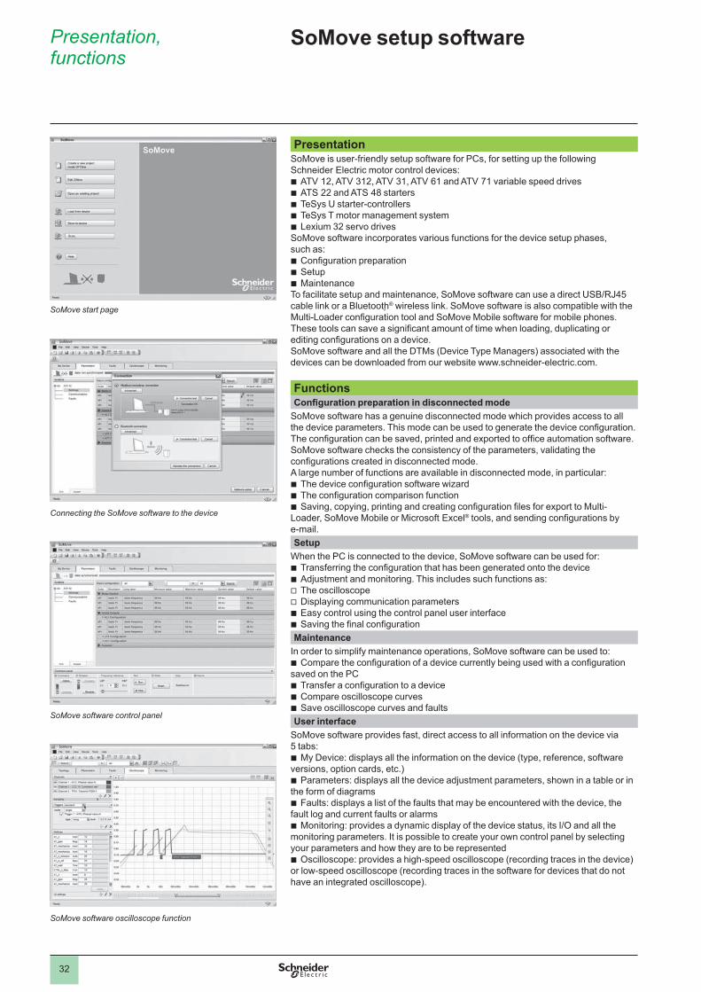
PresentationSoMove is user-friendly setup software for PCs, for setting up the following Schneider Electric motor control devices:
ATV 12, ATV 312, ATV 31, ATV 61 and ATV 71 variable speed drivesATS 22 and ATS 48 startersTeSys U starter-controllers TeSys T motor management systemLexium 32 servo drives
SoMove software incorporates various functions for the device setup phases, such as:
Configuration preparationSetupMaintenance
To facilitate setup and maintenance, SoMove software can use a direct USB/RJ45 cable link or a Bluetooth® wireless link. SoMove software is also compatible with the Multi-Loader configuration tool and SoMove Mobile software for mobile phones.These tools can save a significant amount of time when loading, duplicating or editing configurations on a device.SoMove software and all the DTMs (Device Type Managers) associated with the devices can be downloaded from our website www.schneider-electric.com.
bbbbb
bbb
FunctionsConfiguration preparation in disconnected mode
SoMove software has a genuine disconnected mode which provides access to all the device parameters. This mode can be used to generate the device configuration. The configuration can be saved, printed and exported to office automation software.SoMove software checks the consistency of the parameters, validating the configurations created in disconnected mode.A large number of functions are available in disconnected mode, in particular:
The device configuration software wizardThe configuration comparison functionSaving, copying, printing and creating configuration files for export to Multi-
Loader, SoMove Mobile or Microsoft Excel® tools, and sending configurations by e-mail.
bbb
SetupWhen the PC is connected to the device, SoMove software can be used for:
Transferring the configuration that has been generated onto the deviceAdjustment and monitoring. This includes such functions as:The oscilloscopeDisplaying communication parametersEasy control using the control panel user interfaceSaving the final configuration
bbvvbb
MaintenanceIn order to simplify maintenance operations, SoMove software can be used to:
Compare the configuration of a device currently being used with a configuration saved on the PC
Transfer a configuration to a deviceCompare oscilloscope curvesSave oscilloscope curves and faults
b
bbb
User interfaceSoMove software provides fast, direct access to all information on the device via 5 tabs:
My Device: displays all the information on the device (type, reference, software versions, option cards, etc.)
Parameters: displays all the device adjustment parameters, shown in a table or in the form of diagrams
Faults: displays a list of the faults that may be encountered with the device, the fault log and current faults or alarms
Monitoring: provides a dynamic display of the device status, its I/O and all the monitoring parameters. It is possible to create your own control panel by selecting your parameters and how they are to be represented
Oscilloscope: provides a high-speed oscilloscope (recording traces in the device) or low-speed oscilloscope (recording traces in the software for devices that do not have an integrated oscilloscope).
b
b
b
b
b
SoMove start page
Connecting the SoMove software to the device
SoMove software control panel
SoMove software oscilloscope function

2
1
3
4
5
6
7
8
9
10
2
1
3
4
5
6
7
8
9
10
33
Functions (continued), references
SoMove setup software
Functions (continued)Connections Modbus serial link
The PC running SoMove software can be connected directly via the RJ45 connector on the device and the USB port on the PC with the USB/RJ45 cable.See references table below.
Bluetooth® wireless linkSoMove software can communicate via Bluetooth® wireless link with a device equipped with the Modbus-Bluetooth® adaptor. This adaptor is connected to the terminal port or the Modbus network port on the device. It has a 10 m range (class 2).If the PC does not have Bluetooth® technology, use the USB-Bluetooth® adaptor.See references table below.
References Designation Description Reference Weight
kgSoMove setup software
Includes:SoMove setup software for PC in
Chinese, English, French, German, Italian and Spanish
DTMs (Device Type Managers) and technical documentation for variable speed drives, starters and servo motors
b
b
(1) –
USB/RJ45 cable Used to connect a PC to the deviceThis cable is 2.5 m long, and has a USB connector (PC end) and an RJ45 connector (device end).
TCSM CNAM 3M002P –
Modbus-Bluetooth®
adaptor Enables the device to communicate via Bluetooth® serial link.Includes:
1 Bluetooth® adaptor (range 10 m, class 2) with an RJ45 connector
For SoMove: 1 x 0.1 m cable with 2 x RJ45 connectors
For TwidoSuite: 1 x 0.1 m cable with 1 RJ45 connector and 1 mini DIN connector
b
b
b
VW3 A8 114 0.155
USB-Bluetooth® adaptor for PC
This adaptor is required for a PC that does not have Bluetooth® technology. It is connected to a USB port on the PC. Range 10 m (class 2)
VW3 A8 115 0.290
Environments SoMove operates in the following PC environments and configurations:
Microsoft Windows® SP3Microsoft Windows® VistaPentium IV (or equivalent), 1 GHz, hard disk with 1 GB available space, 512 MB
of RAM (minimum configuration)
bbb
(1) Available on the “Description of the Motion & Drives offer” DVD-ROM, VW3 A8 200, or on our website www.schneider-electric.com.
VW3 A8 114
PF5
3978
5
SoMove setup software
2
1
3
4
5
6
7
8
9
10
2
1
3
4
5
6
7
8
9
10
34
Presentation, characteristics
Variable speed drives Altivar 312Option: braking resistors
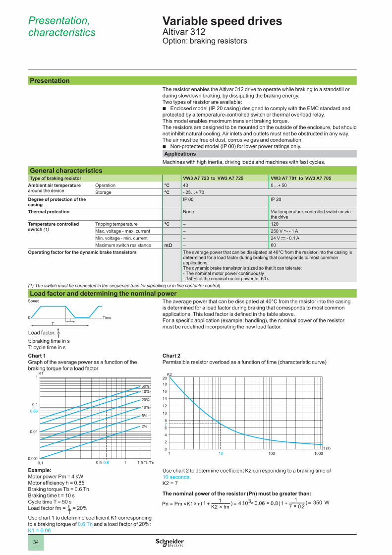
PresentationThe resistor enables the Altivar 312 drive to operate while braking to a standstill or during slowdown braking, by dissipating the braking energy. Two types of resistor are available:
Enclosed model (IP 20 casing) designed to comply with the EMC standard and protected by a temperature-controlled switch or thermal overload relay.This model enables maximum transient braking torque.The resistors are designed to be mounted on the outside of the enclosure, but should not inhibit natural cooling. Air inlets and outlets must not be obstructed in any way. The air must be free of dust, corrosive gas and condensation.
Non-protected model (IP 00) for lower power ratings only. Applications
Machines with high inertia, driving loads and machines with fast cycles.
General characteristicsType of braking resistor VW3 A7 723 to VW3 A7 725 VW3 A7 701 to VW3 A7 705
Ambient air temperature around the device
Operation °C 40 0…+ 50Storage °C - 25…+ 70
Degree of protection of the casing
IP 00 IP 20
Thermal protection None Via temperature-controlled switch or via the drive
Temperature controlled switch (1)
Tripping temperature °C – 120Max. voltage - max. current – 250 V a - 1 AMin. voltage - min. current – 24 V c - 0.1 AMaximum switch resistance mΩ – 60
Operating factor for the dynamic brake transistors The average power that can be dissipated at 40°C from the resistor into the casing is determined for a load factor during braking that corresponds to most common applications.The dynamic brake transistor is sized so that it can tolerate:-�The nominal motor power continuously-�150% of the nominal motor power for 60 s
(1)�The switch must be connected in the sequence (use for signalling or in line contactor control).
Load factor and determining the nominal power
0T
t
Speed
Time
Load factor:t: braking time in sT: cycle time in s
The average power that can be dissipated at 40°C from the resistor into the casing is determined for a load factor during braking that corresponds to most common applications. This load factor is defined in the table above. For a specific application (example: handling), the nominal power of the resistor must be redefined incorporating the new load factor.
Chart 1Graph of the average power as a function of the braking torque for a load factor
0,1
0,01
0,0010,1
0,06
1
0,60,5 1 1,5
K1
2%
20%
40%60%
10%
5%
Tb/Tn
Example:Motor power Pm = 4 kWMotor efficiency h = 0.85Braking torque Tb = 0.6 TnBraking time t = 10 sCycle time T = 50 sLoad factor fm = = 20%
Use chart 1 to determine coefficient K1 corresponding to a braking torque of 0.6 Tn and a load factor of 20%: K1 = 0.06
Chart 2Permissible resistor overload as a function of time (characteristic curve)
0101 100 1000
2
4
6
8
10
12
14
16
1820
t (s)
7
K2
Use chart 2 to determine coefficient K2 corresponding to a braking time of 10 seconds.K2 = 7
The nominal power of the resistor (Pn) must be greater than:
b
b
tT---
tT---
Pn Pm K1 η(1 1K2 fm×---------------------) 4.=+×× 103 0,06 0,8×× (1
17 0,2×-----------------) 350 W=+= . . .

2
1
3
4
5
6
7
8
9
10
2
1
3
4
5
6
7
8
9
10
35
References Variable speed drives Altivar 312Option: braking resistors
For drives Minimum resistor value(1)
Ohmic value
Average power available at
Reference Weight
40°C (2) 50°CΩ Ω W W kg
Non-protected braking resistorsATV 312H018M2…H075M2 40 100 32 28 VW3 A7 723 0.600ATV 312HU11M2, HU15M2 27ATV 312H018M3…H075M3 40ATV 312HU11M3, HU15M3 27ATV 312H037N4…H075N4 80ATV 312HU11N4…HU22N4 54ATV 312H075S6 96ATV 312HU15S6, HU22S6 64ATV 312HU30N4 55 100 40 35 VW3 A7 725 0.850ATV 312HU40N4 36ATV 312HU40S6 44ATV 312HU22M2,ATV 312HU22M3
25 68 32 28 VW3 A7 724 0.600
ATV 312HU30M3 16
Protected braking resistors ATV 312H018M2…H075M2 40 100 58 50 VW3 A7 701 2.000ATV 312HU11M2, HU15M2 27ATV 312H018M3…H075M3 40ATV 312HU11M3, HU15M3 27ATV 312H037N4…H075N4 80ATV 312HU11N4…HU22N4 54ATV 312HU22M2,ATV 312HU22M3
25 60 115 100 VW3 A7 702 2.400
ATV 312HU30M3 16ATV 312HU30N4 55 100 58 50 VW3 A7 701 2.000ATV 312HU40N4 36ATV 312HU55N4 29 60 115 100 VW3 A7 702 2.400ATV 312HU75N4 19ATV 312HU55S6 34ATV 312HU75S6 23ATV 312HU40M3 16 28 231 200 VW3 A7 703 3.500ATV 312HD11N4, HD15N4 20ATV 312HD11S6, HD15S6 24ATV 312HU55M3, HU75M3 8 15 1154 1000 VW3 A7 704 11.000
ATV 312HD11M3, HD15M3 5 10 (3) 1154 1000 VW3 A7 705 11.000
(1)�Depends on the drive rating.(2)�Power that can be dissipated by the resistor at the maximum temperature of 115°C, corresponding to a maximum temperature rise of 75°C in a 40°C environment.(3)�Ohmic value obtained as a function of the connection described in the resistor operating instructions.
VW3 A7 723
5312
31
VW3 A7 723
5312
31
VW3 A7 701
1056
59
VW3 A7 701
1056
59
Dimensions:page 45
Schemes:page 48

2
1
3
4
5
6
7
8
9
10
2
1
3
4
5
6
7
8
9
10
36
Presentation, characteristics
Variable speed drives Altivar 312Option: line chokes
PresentationLine chokes provide improved protection against overvoltages on the line supply and reduce harmonic distortion of the current produced by the drive.
The recommended chokes limit the line current.They have been developed in line with standard IEC 61800-5-1 (VDE 0160 level 1 high-energy overvoltages on the line supply).
The inductance values are defined for a voltage drop between 3% and 5% of the nominal line voltage. Values higher than this will cause loss of torque.
The use of line chokes is recommended in particular for ATV 312HpppM2, ATV 312HpppM3 and ATV 312HpppN4 drives under the following circumstances:
Line supply with significant disturbance from other equipment (interference, overvoltages)
Line supply with voltage imbalance between phases > 1.8% of nominal voltageDrive supplied by a line with very low impedance (in the vicinity of a power
transformer 10 times more powerful than the drive rating) Installation of a large number of frequency inverters on the same lineReduction of overloads on the cos ϕ correction capacitors, if the installation
includes a power factor correction unit
The use of line chokes is mandatory for ATV 312HpppS6 drives.
The prospective short-circuit current at the drive connection point must not exceed the maximum value indicated in the reference tables. The use of chokes allows connection to the following line supplies:
Max. Isc 22 kA for 200/240 V Max. Isc 65 kA for 380/500 V and 525/600V
b
bb
bb
--
CharacteristicsType of line choke VZ1 L004
M010VZ1 L007UM50
VZ1 L018UM20
VW3 A4 551
VW3 A4 552
VW3 A4 553
VW3 A4 554
VW3 A4 555
Conformity to standards IEC 61800-5-1 (VDE 0160 level 1 high-energy overvoltages on the line supply)
Voltage drop Between 3% and 5% of the nominal line voltage. Values higher than this will cause loss of torque.
Degree of protection Choke IP 00Terminals IP 20 IP 10
Inductance value mH 10 5 2 10 4 2 1 0.5
Nominal current A 4 7 18 4 10 16 30 60
Losses W 17 20 30 45 65 75 90 80
Dimensions:page 46
Schemes:page 48
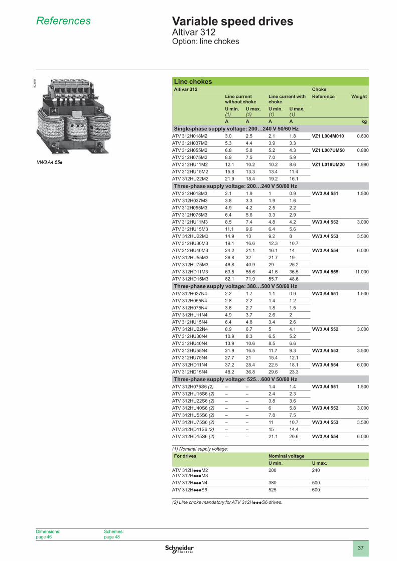
2
1
3
4
5
6
7
8
9
10
2
1
3
4
5
6
7
8
9
10
37
References Variable speed drives Altivar 312Option: line chokes
Line chokes Altivar 312 Choke
Line current without choke
Line current with choke
Reference Weight
U min. (1)
U max. (1)
U min. (1)
U max. (1)
A A A A kgSingle-phase supply voltage: 200…240 V 50/60 Hz
ATV 312H018M2 3.0 2.5 2.1 1.8 VZ1 L004M010 0.630ATV 312H037M2 5.3 4.4 3.9 3.3ATV 312H055M2 6.8 5.8 5.2 4.3 VZ1 L007UM50 0.880ATV 312H075M2 8.9 7.5 7.0 5.9ATV 312HU11M2 12.1 10.2 10.2 8.6 VZ1 L018UM20 1.990ATV 312HU15M2 15.8 13.3 13.4 11.4ATV 312HU22M2 21.9 18.4 19.2 16.1Three-phase supply voltage: 200…240 V 50/60 Hz
ATV 312H018M3 2.1 1.9 1 0.9 VW3 A4 551 1.500ATV 312H037M3 3.8 3.3 1.9 1.6ATV 312H055M3 4.9 4.2 2.5 2.2ATV 312H075M3 6.4 5.6 3.3 2.9ATV 312HU11M3 8.5 7.4 4.8 4.2 VW3 A4 552 3.000ATV 312HU15M3 11.1 9.6 6.4 5.6ATV 312HU22M3 14.9 13 9.2 8 VW3 A4 553 3.500ATV 312HU30M3 19.1 16.6 12.3 10.7ATV 312HU40M3 24.2 21.1 16.1 14 VW3 A4 554 6.000ATV 312HU55M3 36.8 32 21.7 19ATV 312HU75M3 46.8 40.9 29 25.2ATV 312HD11M3 63.5 55.6 41.6 36.5 VW3 A4 555 11.000ATV 312HD15M3 82.1 71.9 55.7 48.6Three-phase supply voltage: 380…500 V 50/60 Hz
ATV 312H037N4 2.2 1.7 1.1 0.9 VW3 A4 551 1.500ATV 312H055N4 2.8 2.2 1.4 1.2ATV 312H075N4 3.6 2.7 1.8 1.5ATV 312HU11N4 4.9 3.7 2.6 2ATV 312HU15N4 6.4 4.8 3.4 2.6ATV 312HU22N4 8.9 6.7 5 4.1 VW3 A4 552 3.000ATV 312HU30N4 10.9 8.3 6.5 5.2ATV 312HU40N4 13.9 10.6 8.5 6.6ATV 312HU55N4 21.9 16.5 11.7 9.3 VW3 A4 553 3.500ATV 312HU75N4 27.7 21 15.4 12.1ATV 312HD11N4 37.2 28.4 22.5 18.1 VW3 A4 554 6.000ATV 312HD15N4 48.2 36.8 29.6 23.3Three-phase supply voltage: 525…600 V 50/60 Hz
ATV 312H075S6 (2) – – 1.4 1.4 VW3 A4 551 1.500ATV 312HU15S6 (2) – – 2.4 2.3ATV 312HU22S6 (2) – – 3.8 3.6ATV 312HU40S6 (2) – – 6 5.8 VW3 A4 552 3.000ATV 312HU55S6 (2) – – 7.8 7.5ATV 312HU75S6 (2) – – 11 10.7 VW3 A4 553 3.500ATV 312HD11S6 (2) – – 15 14.4ATV 312HD15S6 (2) – – 21.1 20.6 VW3 A4 554 6.000
(1)�Nominal supply voltage:For drives Nominal voltage
U min. U max.ATV 312HpppM2 ATV 312HpppM3
200 240
ATV 312HpppN4 380 500ATV 312HpppS6 525 600
(2) Line choke mandatory for ATV 312HpppS6 drives.
VW3 A4 55p
8036
87
VW3 A4 55p
8036
87
Dimensions:page 46
Schemes:page 48
2
1
3
4
5
6
7
8
9
10
2
1
3
4
5
6
7
8
9
10
38
Presentation, characteristics
Variable speed drives Altivar 312Integrated EMC filters and optional additional EMC filters
PresentationIntegrated filters
Altivar 312 drives, apart from ATV 312HpppM3 and ATV312HpppS6, have integrated radio interference input filters to comply with the EMC standard for variable speed electrical power drive “products” IEC 61800-3, categories C2 or C3 for variable speed drives, and to comply with the European EMC (electromagnetic compatibility) directive.
Additional EMC input filtersAdditional EMC input filters (1) enable drives to meet more stringent requirements: they are designed to reduce conducted emissions on the line supply below the limits of standard IEC 61800-3 category C1 or C2 (see page 39).
These additional EMC filters can be mounted beside or under the drive. They act as a support for the drives and are attached to them via tapped holes.
Use according to the type of line supplyAdditional EMC filters can only be used on TN (neutral connection) and TT (neutral to earth) type systems.
Standard IEC 61800-3, appendix D2.1, states that on IT systems (isolated or impedance earthed neutral), filters can cause permanent insulation monitors to operate in a random manner.The effectiveness of additional filters on this type of system depends on the type of impedance between neutral and earth, and therefore cannot be predicted.If a machine has to be installed on an IT system, one solution is to insert an isolation transformer and connect the machine locally on a TN or TT system.
CharacteristicsConformity to standards EN 133200
Degree of protection IP 21 and IP 41 on upper part
Maximum relative humidity 95% non-condensing, no dripping water conforming to IEC 60068-2-3
Ambient air temperature around the device
Operation °C - 10…+ 60Storage °C - 25…+ 70
Maximum operating altitude Without derating m 1000 (above this, derate the current by 1% for every additional 100 m)
Vibration resistance Conforming to IEC 60068-2-6 1.5 mm peak to peak from 3 to 13 Hz1 gn peak from 13 to 150 Hz
Shock resistance Conforming to IEC 60068-2-27 15 gn for 11 ms
Maximum nominal voltage 50/60 Hz single-phase V 240 + 10%
50/60 Hz three-phase V 240 + 10%500 + 10%
(1) Not available for ATV 312HpppS6 drives
Dimensions:page 46
Schemes:page 49

2
1
3
4
5
6
7
8
9
10
2
1
3
4
5
6
7
8
9
10
39
References Variable speed drives Altivar 312Option: additional EMC input filters
Additional EMC input filters For drives FilterReference Maximum length of
shielded cable (1)In(2)
Il(3)
Losses(4)
Reference Weight
IEC 61800-3 (5)Category C2
Category C1
m m A mA W kgSingle-phase supply voltage: 200…240 V 50/60 Hz
ATV 312H018M2ATV 312H037M2ATV 312H055M2ATV 312H075M2
50 20 9 100 3.7 VW3 A31401 0.600
ATV 312HU11M2ATV 312HU15M2
50 20 16 150 6.9 VW3 A31403 0.775
ATV 312HU22M2 50 20 22 80 7.5 VW3 A31405 1.130
Three-phase supply voltage: 200…240 V 50/60 HzATV 312H018M3ATV 312H037M3ATV 312H055M3ATV 312H075M3
5 – 7 7 2.6 VW3 A31402 0.650
ATV 312HU11M3ATV 312HU15M3ATV 312HU22M3
5 – 15 15 9.9 VW3 A31404 1.000
ATV 312HU30M3ATV 312HU40M3
5 – 25 35 15.8 VW3 A31406 1.650
ATV 312HU55M3ATV 312HU75M3
5 – 47 45 19.3 VW3 A31407 3.150
ATV 312HD11M3ATV 312HD15M3
5 – 83 15 35.2 VW3 A31408 5.300
Three-phase supply voltage: 380…500 V 50/60 HzATV 312H037N4ATV 312H055N4ATV 312H075N4ATV 312HU11N4ATV 312HU15N4
50 20 15 15 9.9 VW3 A31404 1.000
ATV 312HU22N4ATV 312HU30N4ATV 312HU40N4
50 20 25 35 15.8 VW3 A31406 1.650
ATV 312HU55N4ATV 312HU75N4
50 20 47 45 19.3 VW3 A31407 3.150
ATV 312HD11N4ATV 312HD15N4
50 20 49 45 27.4 VW3 A31409 4.750
(1)�The filter selection tables give the maximum lengths for shielded cables connecting motors to drives for a switching frequency of 2 to 16 kHz. These maximum lengths are given as examples only, as they vary depending on the stray capacitance of the motors and the cables used. If motors are connected in parallel, the sum of the cable lengths must be taken into account.(2)�In: nominal filter current.(3)�Il: maximum earth leakage current at 50 Hz.(4)�Via heat dissipation, at the nominal filter current (In).(5) Standard IEC 61800-3: EMC immunity and conducted and radiated EMC emissions:- Category C1: public power supply (residential)- Category C2: industrial power supply
VW3 A31405
1055
86
VW3 A31405
1055
86
Dimensions:page 46
Schemes:page 49

2
1
3
4
5
6
7
8
9
10
2
1
3
4
5
6
7
8
9
10
40
Presentation Variable speed drives Altivar 312Options: output filters, motor chokes and ferrite suppressors
PresentationOutput filters and motor chokes can be inserted between the Altivar 312 drive and the motor to:
Limit the dv/dt at the motor terminals (500 to 1500 V/μs), for cables longer than 50 m
Filter interference caused by opening a contactor placed between the filter and the motor
Reduce the motor earth leakage current
The output filter range comprises:LR filter cellsLC filter cells
Ferrite suppressors are necessary on ATV 312HpppM2 and ATV 312H018M3…HU22M3 drives when an output contactor is used.
b
b
b
bb
LR filter cellThis cell comprises 3 high-frequency chokes and 3 resistors.The LR filter cell is particularly suitable for:
Reducing the dv/dt at the motor terminals Using long motor cables (see characteristics table below)
bb
LR filter
U1
W1
V1 M1 3
ATV 312Hppppp
LC filter cell This cell comprises 3 high-frequency chokes and 3 capacitors.The LC filter cell is particularly suitable when using long motor cables (see characteristics table below).
LC filter
U1
W1
V1
ATV 312Hppppp
Motor chokeThe motor choke is particularly suitable for:
Reducing overvoltages at the motor terminals (see length of motor cable in characteristics table below)
Minimizing the current wave, thus reducing motor noise
b
b
M1 3
ATV 312HpppppMotor choke
Ferrite suppressors for downstream contactor openingFerrite suppressors for downstream contactor opening are inserted on the motor cable between ATV 312HpppM2 or ATV 312H018M3…HU22M3 drives and the output contactor.
Ferrite suppressorsOutput contactorATV 312HpppM2
ATV 312H018M3…HU22M3
M1 3
Dimensions:pages 46 and 47

2
1
3
4
5
6
7
8
9
10
2
1
3
4
5
6
7
8
9
10
41
Characteristics, references
Variable speed drives Altivar 312Options: output filters, motor chokes and ferrite suppressors
Characteristics (1)LR filter cells (2)
LC filter cells Motor chokes
VW3 A5845p VW3 A66412 VW3 A4 552 …A4 555
VW3 A4 556
Drive switching frequency kHz 0.5…4 2 ou 4 4…12 4
Length of motor cable Shielded cables m y 100 y 50 y 100
Unshielded cables m y 200 y 100 y 200
Degree of protection IP 20 IP 00 IP 00 IP 20 IP 00
ReferencesLR filter cells Designation For drives Losses Nominal current Reference Weight
W A kgLR filter cells ATV 312H018M2…HU15M2
ATV 312H018M3…HU15M3ATV 312H037N4…HU40N4ATV 312H075S6…HU55S6
150 10 VW3 A58451 7.400
ATV 312HU22M2ATV 312HU22M3, HU30M3ATV 312HU55N4ATV 312HU75S6
180 16 VW3 A58452 7.400
ATV 312HU40M3...HU75M3ATV 312HU75N4...HD15N4ATV 312HD11S6, HD15S6
220 33 VW3 A58453 12.500
LC filter cellsDesignation For drives Reference Weight
kgLC filter cells ATV 312HD11M3
ATV 312HD15M3VW3 A66412 3.500
Motor chokesDesignation For drives Losses Nominal current Reference Weight
W A kgMotor chokes ATV 312HU22N4...HU40N4
ATV 312HU40S6, HU55S665 10 VW3 A4 552 3.000
ATV 312HU22M2ATV 312HU22M3, HU30M3ATV 312HU55N4ATV 312HU75S6
75 16 VW3 A4 553 3.500
ATV 312HU40M3...HU75M3ATV 312HU75N4, HD11N4ATV 312HD11S6, HD15S6
90 30 VW3 A4 554 6.000
ATV 312HD15N4 80 60 VW3 A4 555 11.000ATV 312HD11M3, HD15M3 – 100 VW3 A4 556 16.000
Ferrite suppressors for downstream contactor openingDesignation For drives Sold in lots of Unit reference Weight
kgFerrite suppressors for downstream contactor opening
ATV 312H018M2 3 VW3 A31451 0.300
ATV 312H037M2ATV 312H018M3, H037M3
3 VW3 A31452 0.200
ATV 312H055M2…HU22M2ATV 312H055M3…HU22M3
3 VW3 A31453 0.100
(1)�Filter performance is ensured if the cable lengths between the motor and the drive, given in the above table, are not exceeded. For an application with several motors connected in parallel, the cable length must include all cabling. If a cable longer than that recommended is used, the filters may overheat.(2)�For other LR filter configurations, please consult your Customer Care Centre.
Dimensions:pages 46 and 47
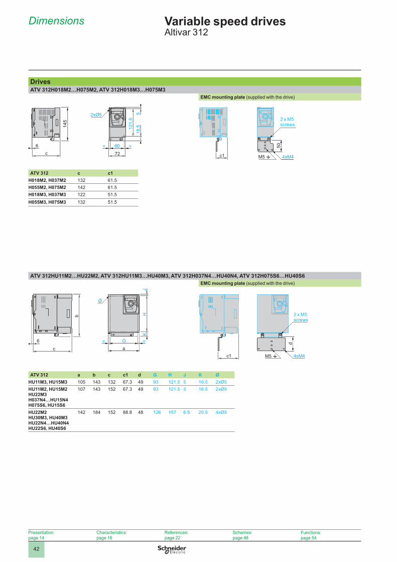
42
Dimensions Variable speed drives Altivar 312
DrivesATV 312H018M2…H075M2, ATV 312H018M3…H075M3
EMC mounting plate (supplied with the drive)
6c
145
121,
55
18,5
60= =72
2xØ5
c1
50
4xM4M5 t
2 x M5 screws
ATV 312 c c1H018M2, H037M2 132 61.5H055M2, H075M2 142 61.5H018M3, H037M3 122 51.5H055M3, H075M3 132 51.5
ATV 312HU11M2…HU22M2, ATV 312HU11M3…HU40M3, ATV 312H037N4…HU40N4, ATV 312H075S6…HU40S6EMC mounting plate (supplied with the drive)
c
6
b
Ø
JK
H
G= =a
c1
d
4xM4M5 t
2 x M5 screws
ATV 312 a b c c1 d G H J K ØHU11M3, HU15M3 105 143 132 67.3 49 93 121.5 5 16.5 2xØ5HU11M2, HU15M2 HU22M3 H037N4…HU15N4 H075S6, HU15S6
107 143 152 67.3 49 93 121.5 5 16.5 2xØ5
HU22M2HU30M3, HU40M3 HU22N4…HU40N4 HU22S6, HU40S6
142 184 152 88.8 48 126 157 6.5 20.5 4xØ5
Presentation:page 14
Characteristics:page 16
References:page 22
Schemes:page 48
Functions:page 54

43
Dimensions (continued) Variable speed drives Altivar 312
Drives (continued)ATV 312HU55M3, HU75M3, ATV 312HU55N4, HU75N4, ATV 312HU55S6, HU75S6
EMC mounting plate (supplied with the drive)
ATV 312HD11M3, HD15M3, ATV 312HD11N4, HD15N4, ATV 312HD11S6, HD15S6EMC mounting plate (supplied with the drive)
1726
232
=21
017
5160=180
4xØ5
1726
232
=21
017
5160=180
4xØ5
75
4xM4 M5 t134,8
2 x M5 screws
75
4xM4 M5 t134,8
2 x M5 screws
245
4xØ6
225
27,5
295
7
= =6192
329,
5
245
4xØ6
225
27,5
295
7
= =6192
329,
5
4xM4
75
M5 t147,6
2xM5 screws
4xM4
75
M5 t147,6
2xM5 screws
Presentation:page 14
Characteristics:page 16
References:page 22
Schemes:page 48
Functions:page 54
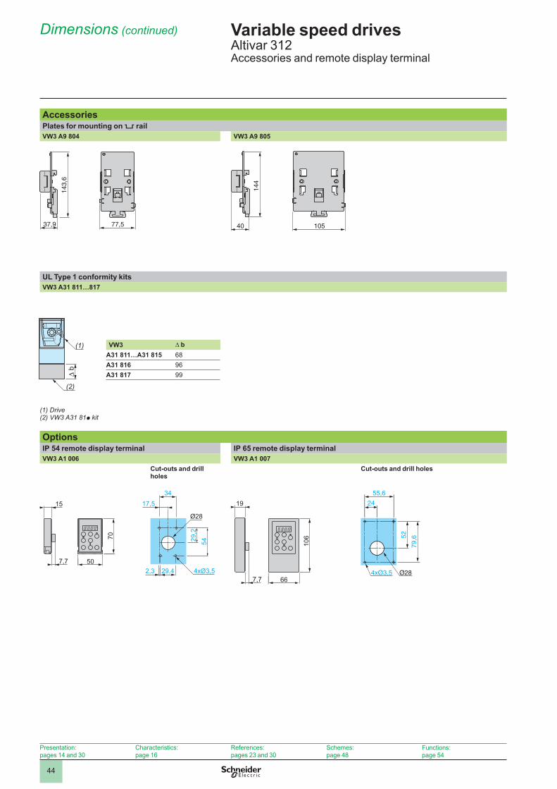
44
Dimensions (continued) Variable speed drives Altivar 312Accessories and remote display terminal
AccessoriesPlates for mounting on 5 railVW3 A9 804 VW3 A9 805
UL Type 1 conformity kits VW3 A31 811…817
VW3 Δ bA31 811…A31 815 68A31 816 96A31 817 99
(1)�Drive(2)�VW3 A31 81p kit
OptionsIP 54 remote display terminal IP 65 remote display terminalVW3 A1 006 VW3 A1 007
Cut-outs and drill holes
Cut-outs and drill holes
7,7
5429,2
29,42,350
Ø28
70
4xØ3,5
15 17,534
24
4xØ3,5
55,6
52
79,6
Ø28
37,9 77,5
143,
6
37,9 77,5
143,
6
40 105
144
40 105
144
b
(2)
(1)
b
(2)
(1)
Presentation:pages 14 and 30
Characteristics:page 16
References:pages 23 and 30
Schemes:page 48
Functions:page 54
7,7 66
106
19
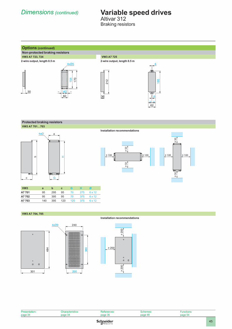
45
Options (continued)Non-protected braking resistorsVW3 A7 723, 724 VW3 A7 725
2-wire output, length 0.5 m
30 40 ==
154
170
4xØ5
60
2-wire output, length 0.5 m
62
195
= =
636
212
6
Protected braking resistorsVW3 A7 701…703
Installation recommendations
VW3 a b c G H ØA7 701 95 295 95 70 275 6 x 12A7 702 95 395 95 70 375 6 x 12A7 703 140 395 120 120 375 6 x 12
VW3 A7 704, 705 Installation recommendations
200
240
301
380
484
4xØ9
u 2
00
u 200
u 2
00
G
a
c
Hb
4xØ
G
a
c
Hb
4xØ
u 5
0
u 100 u 100
u 5
0
u 5
0
u 100 u 100
u 5
0
u 5
0
u 100 u 100
u 5
0
u 5
0
u 100 u 100
u 5
0
Dimensions (continued) Variable speed drives Altivar 312Braking resistors
Presentation:page 34
Characteristics:page 34
References:page 35
Schemes:page 48
Functions:page 54

46
Options (continued)Line chokesVZ1 L004M010, L007UM50, L018UM20
H
Ø
c
G
a
b
VZ1 a b c G H ØL004M010 60 100 80 50 44 4 x 9L007UM50 60 100 95 50 60 4 x 9L018UM20 85 120 105 70 70 5 x 11
Line chokes and motor chokesVW3 A4 551…555 VW3 A4 556
H
8xØ
c
c1
G
G1
a
b
8xØ11x22
100
180
105
181
270
210
VW3 a b c c1 G G1 H ØA4 551 100 135 55 60 40 60 42 6 x 9A4 552, 553 130 155 85 90 60 80.5 62 6 x 12A4 554 155 170 115 135 75 107 90 6 x 12A4 555 180 210 125 165 85 122 105 6 x 12
Additional EMC input filtersMounting the filter under the drive Mounting the filter next to the drive
b H=
=G= =
a
c
4xØ
View from the front
ca
b
4xØ
View from the front
VW3 a b c G H ØA31401, 402 72 195 37 52 180 4.5A31403 107 195 35 85 180 4.5A31404 107 195 42 85 180 4.5A31405 140 235 35 120 215 4.5A31406 140 235 50 120 215 4.5A31407 180 305 60 140 285 5.5A31408 245 395 80 205 375 5.5A31409 245 395 60 205 375 5.5
Dimensions (continued) Variable speed drives Altivar 312Chokes and additional EMC input filters
Presentation:pages 36, 38 and 40
Characteristics:pages 36, 38 and 40
References:pages 37, 39 and 41
Schemes:pages 48 and 49
Functions:page 54

47
Options (continued)LR filter cells LC filter cellVW3 A58451…453 VW3 A66412
4xØ7
c G
H
a
b
90
140
205
378
400
4xØ7
VW3 a b c G HA58451 A58452
169.5 340 123 150 315
A58453 239 467.5 139.5 212 444
Ferrite suppressors for downstream contactor openingVW3 A31451…453
c
b
aØ
VW3 a b c ØA31451 33.5 33 33 13A31452 33 21.5 22.5 9A31453 30 19 19 6
Dimensions (continued) Variable speed drives Altivar 312Output filters and ferrite suppressors
Presentation:page 40
Characteristics:page 40
References:page 41
Schemes:page 48
Functions:page 54

2
1
3
4
5
6
7
8
9
10
2
1
3
4
5
6
7
8
9
10
48
ATV 312HpppM2 ATV 312HpppM3, ATV 312HpppN4, ATV 312HpppS6 Single-phase power supply Three-phase power supply
X-Y mA
0 ± 10 V
R1A
R1C
R1B
(2)
R2A
R2C LI
1
LI2
LI3
LI4
+ 24
CLI
(3)
LI5
LI6
PA/+
W P0
PC
/-
U V AI2
CO
M
AI3
AO
V
AO
C
PB + 10
AI1
L1 L2
U1
W1
V1
M 3
(1)
T1KM1
A2A1
3 4 5 6
Q2
1 2
R1A R1C 13 14
Q1
2 4 6
KM1
Q21 2 Q3 S2 S1
KM1
1 3 5
A1
A1
1 3
2 4
abc
Braking resistor
(if used)Reference potentiometer SZ1 RV1202
ATV 312HpppM2
PA/+
W P0
PC
/-
U V AI2
CO
M
AI3
AO
V
AO
C
PB + 10
AI1
L1 L2 L3
R1A
R1C
R1B LI
1
LI2
LI3
LI4
+ 24
CLI
U1
W1
V1
M 3
X-Y mA
0 ± 10 V
(3)
(2)
(1)
LI5
LI6
T1KM1
A2A1
3 4 5 6
Q2
1 2
R1A R1C 13 14
Q1
2 4 6
KM1
Q21 2 Q3 S2 S1
KM1
1 3 5
A1
A1
2 4 6
1 3 5
R2A
R2C
abc
Braking resistor
(if used)
Reference potentiometer SZ1 RV1202
ATV 312HpppM3ATV 312HpppN4ATV 312HpppS6
(1) Line choke (single-phase or three-phase).(2) Fault relay contacts. Used for remote signalling of the drive status.(3) Connection of the common for the logic inputs depends on the position of the switch (see schemes below).Note: All terminals are located at the bottom of the drive. Install interference suppressors on all inductive circuits near the drive or connected on the same circuit, such as relays, contactors, solenoid valves, fluorescent lighting, etc.Compatible components (for a complete list of references, please refer to the “Motor starter solutions - Control and protection components” catalogue).Item no. Designation
KM1 Line contactor LC1 ppp + suppressor module LA4 DA2U (see page 52)Q1 GV2 L magnetic circuit-breaker or Compact NS circuit-breaker (see page 52)Q2 GV2 L magnetic circuit-breaker rated at twice the nominal primary current of T1Q3 GB2 CB05 thermal magnetic circuit breakerS1, S2 XB4 B or XB5 A pushbuttonsT1 100 VA transformer 220 V secondaryExamples of recommended schemesLogic input switches AOC output
Source position Sink position CLI position with PLC transistor outputs Wired as logic output
+ 24
V
0 V
LI1
ATV 31224 V
CO
M
LI1
ATV 312
CLI
CO
M
LI1
0 V
24 V
PLC
ATV 312
CLI
CO
M
LI1
0 V 24 VPLC
ATV 312
CO
M
AO
C
24 V relay 10 mAor 24V PLC inputor LED
ATV 312 control terminals
2-wire control 3-wire control Voltage analog inputs Current analog inputExternal + 10 V External ± 10 V 0-20 mA, 4-20 mA, X-Y mA
LI1+ 24
V
LIx
LI1: Forward LIx: Reverse
ATV 312 control terminals
LI1
LI2+ 24
V
LIx
LI1: Stop LI2: Forward LIx: Reverse
ATV 312 control terminals
AI1
0 V
+ 10 V
Speed reference potentiometer 2.2 to 10 kW
ATV 312 control terminals
AI2
0 V
± 10 V
ATV 312 control terminals
AI3
0 V
Source0-20 mA 4-20 mAX-Y mA
ATV 312 control terminals
Schemes Variable speed drivesAltivar 312
Presentation:page 14
Characteristics:page 16
References:page 22
Dimensions:page 42
Functions:page 54

2
1
3
4
5
6
7
8
9
10
2
1
3
4
5
6
7
8
9
10
49
Additional EMC input filters VW3 A31 40pSingle-phase power supply Three-phase power supply
L'1
L'2
L1 L2
L1 L2
ATV A31 40p
ATV 312HpppM2
L'1
L'2
L'3
L1 L2 L3
L1 L2 L3
ATV A31 40p
ATV 312HpppM3ATV 312HpppN4ATV 312HpppS6
Connections ensuring conformity to EMC standardsPrinciple
Earths between the drive, motor and cable shielding must have “high-frequency” equipotentiality.Use shielded cables with the shielding connected to earth throughout 360° at both ends for the motor cable, the braking resistor cable and
the control-signal cables. Metal conduit or ducting can be used for part of the shielding length provided that there is no break in the continuity of the earth connection.
Ensure maximum separation between the power supply cable and the motor cable.
bb
b
Installation diagram
2
5
74
683
9
1
Steel plate to be mounted on the drive (earthed casing)Altivar 312 driveUnshielded power supply wires or cableUnshielded wires or cable for the output of the fault relay contactsAttach and earth the shielding of cables 6, 7 and 8 as close as possible to the drive:
Strip the cable to expose the shieldingAttach the cable to the plate 1, attaching the clamp on the stripped part of the
shielding.The shielding must be clamped tightly enough to the metal sheet to ensure good contact.For cables 6, 7 and 8, the shielding must be connected to earth at both ends. The shielding must be continuous, and if intermediate terminals are used, they must be placed in EMC shielded metal boxes.Shielded cable for connecting the motorShielded cable for connecting the control-signal wiring. For applications requiring several conductors, use cables with a small cross-section (0.5 mm2).Shielded cable for connecting the braking resistorPE cable (green-yellow)
1 2 3 4 5
--
6 7
8 9
Note: The HF equipotential earth connection between the drive, motor and cable shielding does not remove the need to connect the PE conductors (green-yellow) to the appropriate terminals on each device. If using an additional EMC input filter, it must be mounted under the drive and connected directly to the line supply via an unshielded cable. Link 3 on the drive is then via the filter output cable.
Operation on an IT system (isolated or impedance earthed neutral)Use a permanent insulation monitor compatible with non-linear loads, such as the Schneider Electric XM200 (please consult our website www.schneider-electric.com or contact your Customer Care Center). ATV 312HpppM2 and ATV 312HpppN4 drives have integrated EMC filters. For use on an IT system, these filters can be disconnected by removing their earth connection:
For ATV 312H018M2…HU22M2 and H037N4…HU40N4 drives, remove a jumper to disconnect the filter.For ATV 312HU55N4…HD15N4 drives, move the wire with the cable tag to disconnect the filter.
bb
Schemes (continued), installation recommendations
Variable speed drives Altivar 312
Presentation:pages 14 and 38
Characteristics:pages 16 and 38
References:pages 22 and 39
Dimensions:pages 42 and 46
Functions:page 54
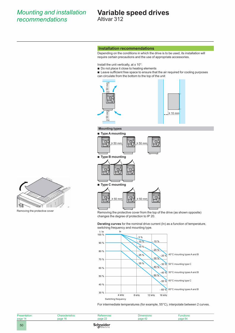
2
1
3
4
5
6
7
8
9
10
2
1
3
4
5
6
7
8
9
10
50
Installation recommendationsDepending on the conditions in which the drive is to be used, its installation will require certain precautions and the use of appropriate accessories.
Install the unit vertically, at ± 10°:Do not place it close to heating elementsLeave sufficient free space to ensure that the air required for cooling purposes
can circulate from the bottom to the top of the unit
bb
u 50
mm
u 50
mm u 10 mm
Mounting types Type A mounting
u 50 mm u 50 mm
Type B mounting
Type C mounting
u 50 mm u 50 mm
Removing the protective cover from the top of the drive (as shown opposite) changes the degree of protection to IP 20.
Derating curves for the nominal drive current (In) as a function of temperature, switching frequency and mounting type.
I / In100 %
- 5 %
- 10 %90 %
80 %
70 %
60 %
50 %
40 %
30 %4 kHz 8 kHz 12 kHz 16 kHz
In
- 15 %
- 25 %
- 35 %
- 10 %
- 20 %
- 30 %
- 40 %
- 50 %
- 25 %
- 35 %
- 45 %
- 55 %
- 65 %
Switching frequency
40°C mounting types A and B
50°C mounting type C
50°C mounting types A and B
60°C mounting type C
60°C mounting types A and B
For intermediate temperatures (for example, 55°C), interpolate between 2 curves.
b
b
b
Variable speed drives Altivar 312
Mounting and installation recommendations
Presentation:page 14
Characteristics:page 16
References:page 22
Dimensions:page 42
Functions:page 54
Removing the protective cover
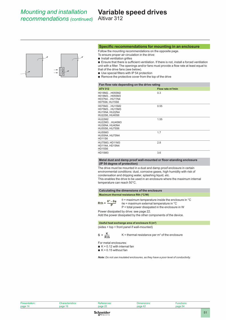
2
1
3
4
5
6
7
8
9
10
2
1
3
4
5
6
7
8
9
10
51
Specific recommendations for mounting in an enclosureFollow the mounting recommendations on the opposite page.To ensure proper air circulation in the drive:
Install ventilation grillesEnsure that there is sufficient ventilation. If there is not, install a forced ventilation
unit with a filter. The openings and/or fans must provide a flow rate at least equal to that of the drive fans (see below).
Use special filters with IP 54 protectionRemove the protective cover from the top of the drive
bb
bb
Fan flow rate depending on the drive ratingATV 312 Flow rate m3/min
H018M2…H055M2H018M3…H055M3H037N4…HU11N4H075S6, HU15S6
0.3
H075M2…HU15M2H075M3…HU15M3HU15N4, HU22N4HU22S6, HU40S6
0.55
HU22M2HU22M3…HU40M3HU30N4, HU40N4HU55S6, HU75S6
1.55
HU55M3HU55N4, HU75N4HD11S6
1.7
HU75M3, HD11M3HD11N4, HD15N4HD15S6
2.8
HD15M3 3.6
Metal dust and damp proof wall-mounted or floor-standing enclosure (IP 54 degree of protection)
The drive must be mounted in a dust and damp proof enclosure in certain environmental conditions: dust, corrosive gases, high humidity with risk of condensation and dripping water, splashing liquid, etc.This enables the drive to be used in an enclosure where the maximum internal temperature can reach 50°C.
Calculating the dimensions of the enclosureMaximum thermal resistance Rth (°C/W)
θ = maximum temperature inside the enclosure in °Cθe = maximum external temperature in °CP = total power dissipated in the enclosure in W
Power dissipated by drive: see page 22.Add the power dissipated by the other components of the device.
Useful heat exchange area of enclosure S (m2)(sides + top + front panel if wall-mounted)
K = thermal resistance per m2 of the enclosure
For metal enclosures: K = 0.12 with internal fan K = 0.15 without fan
bb
Note: Do not use insulated enclosures, as they have a poor level of conductivity.
R th e–P------------------=R th e–P------------------=
S KR th----------=S KR th----------=
Mounting and installation recommendations (continued)
Variable speed drives Altivar 312
Presentation:page 14
Characteristics:page 16
References:page 22
Dimensions:page 42
Functions:page 54

2
1
3
4
5
6
7
8
9
10
2
1
3
4
5
6
7
8
9
10
52
Combinations Variable speed drives Altivar 312Motor starters
ApplicationsThe combinations listed below can be used to assemble a complete motor starter comprising a circuit-breaker, a contactor and an Altivar 312 variable speed drive.The circuit-breaker provides protection against accidental short-circuits, disconnection and, if necessary, isolation.The contactor controls and manages any safety features and isolates the motor on stopping.The Altivar 312 drive is protected electronically against short-circuits between phases and between phase and earth. It therefore ensures continuity of service and thermal protection of the motor.
Motor startersStandard power rating of 50/60 Hz 4-pole motors (1)
Drive Circuit-breaker Contactor (2) Add voltage reference to basic reference to obtain full reference (3)Reference Reference Rating
kW HP ASingle-phase supply voltage: 200…240 V
0.18 0.25 ATV 312H018M2 GV2 L08 4 LC1 D09pp
0.37 0.5 ATV 312H037M2 GV2 L10 6.3 LC1 D09pp
0.55 0.75 ATV 312H055M2 GV2 L14 10 LC1 D09pp
0.75 1 ATV 312H075M2 GV2 L14 10 LC1 D09pp
1.1 1.5 ATV 312HU11M2 GV2 L16 14 LC1 D09pp
1.5 2 ATV 312HU15M2 GV2 L20 18 LC1 D09pp
2.2 3 ATV 312HU22M2 GV2 L22 25 LC1 D09pp
Three-phase supply voltage: 200…240 V0.18 0.25 ATV 312H018M3 GV2 L07 2.5 LC1 D09pp
0.37 0.5 ATV 312H037M3 GV2 L08 4 LC1 D09pp
0.55 0.75 ATV 312H055M3 GV2 L10 6.3 LC1 D09pp
0.75 1 ATV 312H075M3 GV2 L14 10 LC1 D09pp
1.1 1.5 ATV 312HU11M3 GV2 L14 10 LC1 D09pp
1.5 2 ATV 312HU15M3 GV2 L16 14 LC1 D09pp
2.2 3 ATV 312HU22M3 GV2 L20 18 LC1 D09pp
3 – ATV 312HU30M3 GV2 L22 25 LC1 D09pp
4 5 ATV 312HU40M3 GV2 L22 25 LC1 D09pp
5.5 7.5 ATV 312HU55M3 GV3 L40 40 LC1 D32pp
7.5 10 ATV 312HU75M3 GV3 L50 50 LC1 D32pp
11 15 ATV 312HD11M3 GV3 L65 65 LC1 D50pp
15 20 ATV 312HD15M3 NS100HMA 100 LC1 D80pp
Three-phase supply voltage: 380…500 V0.37 0.5 ATV 312H037N4 GV2 L07 2.5 LC1 D09pp
0.55 0.75 ATV 312H055N4 GV2 L08 4 LC1 D09pp
0.75 1 ATV 312H075N4 GV2 L08 4 LC1 D09pp
1.1 1.5 ATV 312HU11N4 GV2 L10 6.3 LC1 D09pp
1.5 2 ATV 312HU15N4 GV2 L14 10 LC1 D09pp
2.2 3 ATV 312HU22N4 GV2 L14 10 LC1 D09pp
3 – ATV 312HU30N4 GV2 L16 14 LC1 D09pp
4 5 ATV 312HU40N4 GV2 L16 14 LC1 D09pp
5.5 7.5 ATV 312HU55N4 GV2 L22 25 LC1 D09pp
7.5 10 ATV 312HU75N4 GV2 L32 32 LC1 D18pp
11 15 ATV 312HD11N4 GV3 L40 40 LC1 D25pp
15 20 ATV 312HD15N4 GV3 L50 50 LC1 D32pp
(1) The values expressed in HP conform to the NEC (National Electrical Code).(2) Composition of contactors LC1-D09/D18/D25/D32/D50/D80:
3 poles + 1 N/O auxiliary contact + 1 N/C auxiliary contact.(3) Replace pp with the control circuit voltage reference indicated in the table below:AC control circuit
Volts a 24 48 110 220 230 230/240LC1-D 50/60 Hz B7 E7 F7 M7 P7 U7For other voltages between 24 V and 660 V, or a DC control circuit, please refer to the “Motor starter solutions - Control and protection components” catalogue.
GV2 L14 + LC1 D09 + ATV 312H075M2
PF5
3985
1P
F539
852
PF5
3985
0
GV2 L14 + LC1 D09 + ATV 312H075M2
PF5
3985
1P
F539
852
PF5
3985
0

2
1
3
4
5
6
7
8
9
10
2
1
3
4
5
6
7
8
9
10
53
Combinations (continued) Variable speed drives Altivar 312Motor starters
Motor starters (continued)Standard power rating of 50/60 Hz 4-pole motors (1)
Drive Circuit-breaker Contactor (2) Add voltage reference to basic reference to obtain full reference (3)Reference Reference Rating
kW HP AThree-phase supply voltage: 525…600 V
0.75 1 ATV 312H075S6 GV2 L08 4 LC1 D09pp
1.5 2 ATV 312HU15S6 GV2 L10 6.3 LC1 D09pp
2.2 3 ATV 312HU22S6 GV2 L14 10 LC1 D09pp
4 5 ATV 312HU40S6 GV2 L16 14 LC1 D09pp
5.5 7.5 ATV 312HU55S6 GV2 L20 18 LC1 D09pp
7.5 10 ATV 312HU75S6 GV2 L22 25 LC1 D09pp
11 15 ATV 312HD11S6 GV2 L32 32 LC1 D18pp
15 20 ATV 312HD15S6 GV3 L40 40 LC1 D25pp
(1) The values expressed in HP conform to the NEC (National Electrical Code).(2) Composition of contactors LC1-D09/D18/D25:
3 poles + 1 N/O auxiliary contact + 1 N/C auxiliary contact.(3) Replace pp with the control circuit voltage reference indicated in the table below:AC control circuit
Volts a 24 48 110 220 230 230/240LC1-D 50/60 Hz B7 E7 F7 M7 P7 U7For other voltages between 24 V and 660 V, or a DC control circuit, please refer to the “Motor starter solutions - Control and protection components” catalogue.
GV3 L40 + LC1 D25 + ATV 312HD15S6
PF5
3985
3P
F539
854
PF5
3985
5
GV3 L40 + LC1 D25 + ATV 312HD15S6
PF5
3985
3P
F539
854
PF5
3985
5

2
1
3
4
5
6
7
8
9
10
2
1
3
4
5
6
7
8
9
10
54
Summary of functions Drive factory configuration
Presentation page 55
Human-Machine Interface (HMI)Description page 55
Application functionsOperating speed range page 56Acceleration and deceleration ramp times page 56Acceleration and deceleration ramp profiles page 56Ramp switching page 57Automatic adaptation of deceleration ramp page 57Voltage/frequency ratio page 58Auto-tuning page 58Switching frequency, noise reduction page 58Skip frequencies page 59Speed reference page 59Analog inputs page 59Preset speeds page 59+/- speed page 60Save reference page 60Jog operation page 61Command and reference channels page 61Reference switching page 61Summing inputs page 61PI regulator page 62Current limit switching page 62Limiting low speed operating time page 62Motor switching page 62Control mode switching page 632-wire control page 633-wire control page 63Forced local mode page 63Freewheel stop page 63Fast stop page 63DC injection stop page 63Brake control page 64Limit switch management page 64Monitoring page 64Fault management page 65Fault reset page 65General reset (disables all faults) page 65Controlled stop on loss of line supply page 65Stop mode in the event of a fault page 65Automatic catching of a spinning load with speed detection (“catch on the fly”) page 66Automatic restart page 66Derated operation in the event of an undervoltage page 66Fault relay, unlocking page 66Resetting operating time to zero page 66Motor thermal protection page 67Drive thermal protection page 67R1, R2 relay configuration page 67AOC/AOV analog outputs page 68Saving and retrieving the configuration page 68
Function compatibility tablePresentation page 69
Functions Variable speed drivesAltivar 312
Presentation:page 14
Characteristics:page 16
References:page 22
Dimensions:page 42
Schemes:page 48

2
1
3
4
5
6
7
8
9
10
2
1
3
4
5
6
7
8
9
10
55
Drive factory configurationThe Altivar 312 drive is configured to allow a quick start-up for most applications.Factory configuration:
Nominal motor frequency: 50 HzMotor voltage: 230 V (ATV 312HpppM2, ATV 312HpppM3),
400 V (ATV 312HpppN4) or 600 V (ATV 312HpppS6)Linear ramp times: 3 secondsLow speed (LSP): 0 Hz/High speed (HSP): 50 HzNormal stop mode on deceleration rampStop mode in the event of a fault: freewheelMotor thermal current = nominal drive currentStandstill injection braking current = 0.7 x nominal drive current, for 0.5 secondsConstant torque operation with sensorless flux vector controlLogic inputs: 2 directions of operation (LI1, LI2), 2-wire control4 preset speeds (LI3, LI4): LSP (low speed), 10 Hz, 15 Hz, 20 HzAnalog inputs: AI1 speed reference (0 +10 V)AI2 (0 ± 10 V) summing of AI1AI3 (4-20 mA) not configuredRelay R1: fault relayRelay R2: not assignedAnalog output AOC: 0-20 mA, image of the motor frequencyAutomatic adaptation of the deceleration ramp in the event of overbrakingSwitching frequency 4 kHz, random frequency
Human-Machine Interface (HMI)Description
1 Display:4-digit displayDisplay of numeric values and codesIndication of the unit of the displayed value
2 Display of the drive status:REF: Reference mode. This mode is used to display the motor frequency
reference of the active reference channel (terminals, local mode, remote display terminal or Modbus serial link). In local mode, the reference can be modified using the navigation button 4, if the function is configured.
MON: Monitoring mode. This mode is used to display the monitoring parameters when the drive is running.
CONF: Configuration mode. This mode is used to configure the drive parameters. These parameters can be modified using the SoMove setup software.
3 Use of the keys:MODE is used to access one of the following modes:Reference mode REFMonitoring mode MONConfiguration mode CONF
Note: This key cannot be accessed if the front panel door is closed.ESC: Aborts a value, a parameter or a menu to return to the previous selectionsSTOP/RESET: Local motor stop command, clears drive faults (key active in
factory configuration)RUN: Local motor run command, if its activation is programmed
4 Use of the navigation button:Rotate: Increases or decreases the value, or goes to the next valuePress: Saves the current value or selects the valueThe button can be used as a potentiometer in local mode
5 Cover that can be removed for access to the RUN and STOP/RESET keys.
6 It is possible to lock the front panel door with a lead seal.
bbb
b
b
b
bvvv
bb
b
bbb
bb
bbbbbbbbvvbvvvbbbbb
Functions (continued) Variable speed drivesAltivar 312
Presentation:page 14
Characteristics:page 16
References:page 22
Dimensions:page 42
Schemes:page 48
MODEMODE
MODE
REF
MON CONF
Motor frequency reference
Configuration of parameters
Monitoring parameters
3 operating modes: REF, MON and CONF
4
5
1
3
2
3
ATV 312H075M2 with front panel door open
41
63
2
5
3
ATV 312H075M2 with front panel door closed, without cover 5: STOP/RESET and RUN keys accessible
3
56
14
2
ATV 312H075M2 with front panel door closed, with cover 5: STOP/RESET and RUN keys not accessible
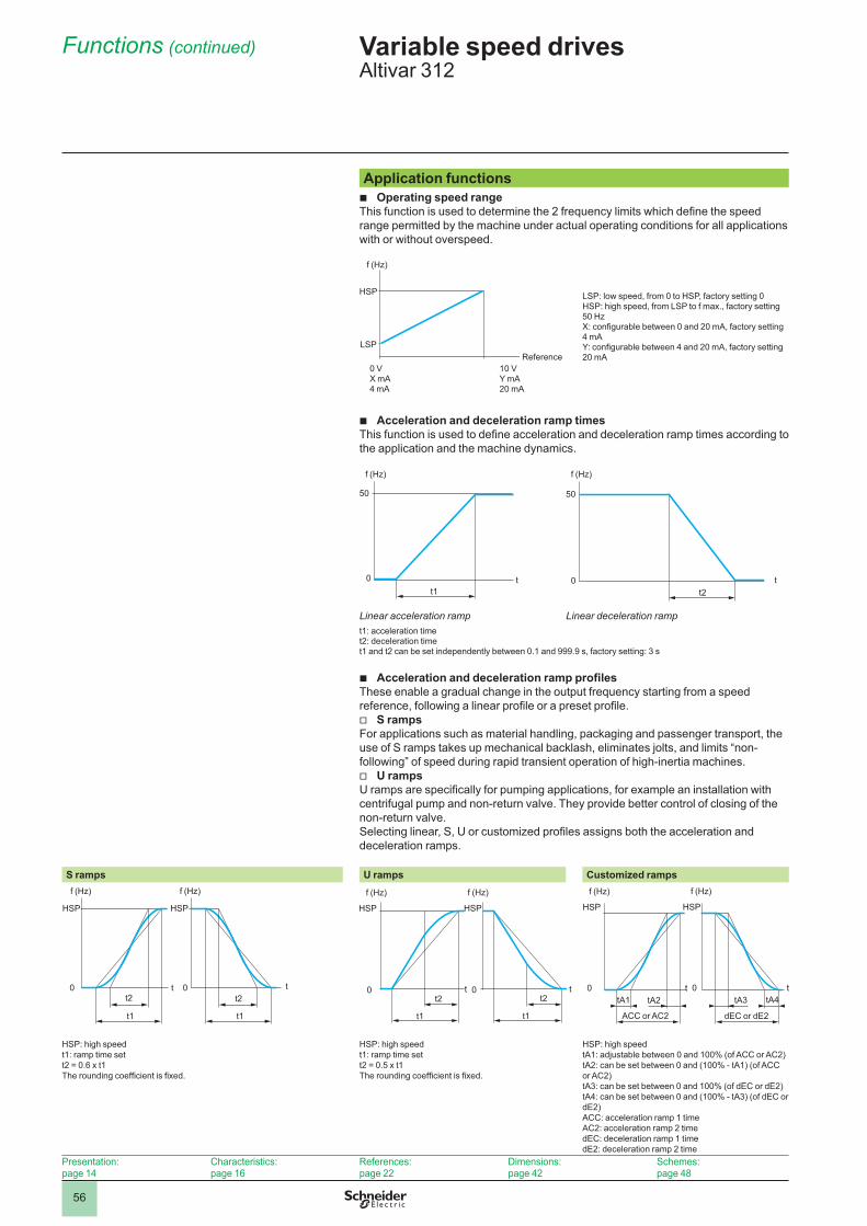
2
1
3
4
5
6
7
8
9
10
2
1
3
4
5
6
7
8
9
10
56
Application functionsOperating speed range
This function is used to determine the 2 frequency limits which define the speed range permitted by the machine under actual operating conditions for all applications with or without overspeed.
f (Hz)
HSP
LSP
0 VX mA4 mA
10 VY mA20 mA
Reference
LSP: low speed, from 0 to HSP, factory setting 0HSP: high speed, from LSP to f max., factory setting 50 HzX: configurable between 0 and 20 mA, factory setting 4 mAY: configurable between 4 and 20 mA, factory setting 20 mA
Acceleration and deceleration ramp times This function is used to define acceleration and deceleration ramp times according to the application and the machine dynamics.
50
f (Hz)
0t1
t
50
f (Hz)
0t2
t
Linear acceleration ramp Linear deceleration rampt1: acceleration timet2: deceleration time t1 and t2 can be set independently between 0.1 and 999.9 s, factory setting: 3 s
Acceleration and deceleration ramp profilesThese enable a gradual change in the output frequency starting from a speed reference, following a linear profile or a preset profile.
S ramps For applications such as material handling, packaging and passenger transport, the use of S ramps takes up mechanical backlash, eliminates jolts, and limits “non-following” of speed during rapid transient operation of high-inertia machines.
U ramps U ramps are specifically for pumping applications, for example an installation with centrifugal pump and non-return valve. They provide better control of closing of the non-return valve.Selecting linear, S, U or customized profiles assigns both the acceleration and deceleration ramps.
S ramps U ramps Customized rampsf (Hz) f (Hz)
HSP HSP
0 0t tt2
t1
t2
t1
f (Hz)
HSP
0 tt2
t1
f (Hz)
HSP
0 tt2
t1
f (Hz)
HSP
0 ttA1
ACC or AC2
f (Hz)
HSP
0 ttA2 tA3 tA4
dEC or dE2
HSP: high speedt1: ramp time sett2 = 0.6 x t1The rounding coefficient is fixed.
HSP: high speedt1: ramp time sett2 = 0.5 x t1The rounding coefficient is fixed.
HSP: high speedtA1: adjustable between 0 and 100% (of ACC or AC2)tA2: can be set between 0 and (100% - tA1) (of ACC or AC2)tA3: can be set between 0 and 100% (of dEC or dE2)tA4: can be set between 0 and (100% - tA3) (of dEC or dE2)ACC: acceleration ramp 1 timeAC2: acceleration ramp 2 timedEC: deceleration ramp 1 timedE2: deceleration ramp 2 time
b
b
b
v
v
Presentation:page 14
Characteristics:page 16
References:page 22
Dimensions:page 42
Schemes:page 48
Functions (continued) Variable speed drivesAltivar 312
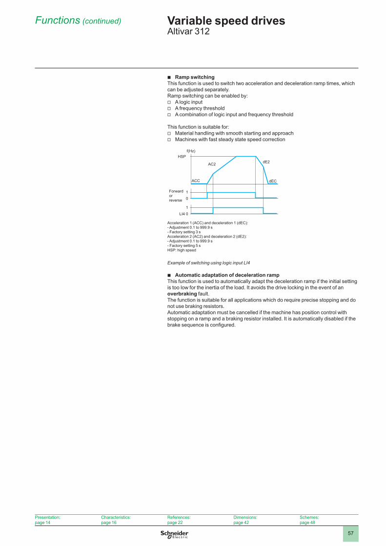
2
1
3
4
5
6
7
8
9
10
2
1
3
4
5
6
7
8
9
10
57
Ramp switchingThis function is used to switch two acceleration and deceleration ramp times, which can be adjusted separately. Ramp switching can be enabled by:
A logic inputA frequency thresholdA combination of logic input and frequency threshold
This function is suitable for:Material handling with smooth starting and approachMachines with fast steady state speed correction
f(Hz)
01
LI4 01
AC2
ACC
Forward or reverse
dE2
dEC
Acceleration 1 (ACC) and deceleration 1 (dEC):- Adjustment 0.1 to 999.9 s- Factory setting 3 s Acceleration 2 (AC2) and deceleration 2 (dE2):- Adjustment 0.1 to 999.9 s - Factory setting 5 sHSP: high speed
HSP
Example of switching using logic input LI4
Automatic adaptation of deceleration rampThis function is used to automatically adapt the deceleration ramp if the initial setting is too low for the inertia of the load. It avoids the drive locking in the event of an overbraking fault. The function is suitable for all applications which do require precise stopping and do not use braking resistors.Automatic adaptation must be cancelled if the machine has position control with stopping on a ramp and a braking resistor installed. It is automatically disabled if the brake sequence is configured.
b
vvv
vv
b
Presentation:page 14
Characteristics:page 16
References:page 22
Dimensions:page 42
Schemes:page 48
Functions (continued) Variable speed drivesAltivar 312

2
1
3
4
5
6
7
8
9
10
2
1
3
4
5
6
7
8
9
10
58
Voltage/frequency ratio Motor and power supply characteristics
This function is used to determine the limit values for the voltage/frequency ratio according to the characteristics of the line supply, motor and application.The following values should be set for constant or variable torque applications with or without overspeed:
The base frequency corresponding to the line supplyThe nominal motor frequency (in Hz) given on the motor rating plateThe nominal motor voltage (in V) given on the motor rating plateThe maximum output frequency of the drive (in Hz)
Type of voltage/frequency ratioThis is used to adapt the voltage/frequency ratio to the application in order to optimize performance for the following applications:
Constant torque applications (machines with average loads operating at low speed) with motors connected in parallel or special motors (e.g. resistive cage motor): ratio L
Variable torque applications (pumps, fans): ratio PMachines with heavy loads operating at low speed, machines with fast cycles, with
(sensorless) flux vector control: ratio nEnergy saving, for machines with slow torque and speed variations: ratio nLd.
The voltage is automatically reduced to minimum according to the necessary torque.
Ln
P
U (V)
Un
frnf (Hz)
Un: nominal motor voltagefrn: nominal motor frequency
Auto-tuningAuto-tuning can be performed:
Voluntarily by the operator using dialogue tools via local control or the serial linkEach time the drive is switched onOn each run commandBy enabling a logic input
Auto-tuning is used to optimize application performance.
Switching frequency, noise reductionAdjusting the switching frequency setting reduces the noise generated by the motor.The switching frequency is modulated randomly in order to avoid resonance. This function can be disabled if it causes instability.High frequency switching of the intermediate DC voltage can be used to supply the motor with a current wave that has little harmonic distortion. The switching frequency can be adjusted during operation to reduce the noise generated by the motor.Value: 2 to 16 kHz. Factory setting 4 kHzFor all applications which require low motor noise.
bv
----
v
-
--
-
b
vvvv
b
Presentation:page 14
Characteristics:page 16
References:page 22
Dimensions:page 42
Schemes:page 48
Functions (continued) Variable speed drivesAltivar 312

2
1
3
4
5
6
7
8
9
10
2
1
3
4
5
6
7
8
9
10
59
Skip frequencies This function suppresses one or two critical speeds that may cause mechanical resonance.It is possible to prohibit prolonged operation of the motor on 1 or 2 frequency bands (± 1 Hz), around an adjustable frequency on the speed range.This function is suitable for lightweight machines, bulk product conveyors with an unbalanced motor, fans and centrifugal pumps.
2 Hz
Motor speed change depending on the skip frequency reference
Reference
f (Hz)
Speed referenceThe speed reference can come from different sources, depending on the drive configuration:
References provided by 3 analog inputsThe navigation button referenceThe +/- speed function via logic input, using the keypad or remote display terminal
keysThe remote display terminal referenceSpeed references provided by the communication bus or networks
These sources are managed by programming the reference functions and channels.
Analog inputsThere are 3 analog inputs:
2 voltage inputs:0-10 V (AI1)± 10 V (AI2)1 current input:X-Y mA (AI3), where X is configurable between 0 and 20 mA, and Y is configurable
between 4 and 20 mA
Preset speeds This function is used to switch preset speed references.Choose between 2, 4, 8 or 16 preset speeds.Enabled by means of 1, 2, 3 or 4 logic inputs.The preset speeds are adjustable in increments of 0.1 Hz from 0 Hz to 500 Hz.This function is suitable for material handling and machines with several operating speeds.
1
101520
1
LI3 0
1
LI4 0
LI2 0
t
t
t
t
f (Hz)
LSP
Forward or
Reverse
The speed obtained with inputs LI3 and LI4 at state 0 is LSP or the speed reference, depending on the level of analog inputs AI1, AI2 and AI3.
Factory settings:
1st speed: LSP (low speed or speed reference)
2nd speed: 10 Hz
3rd speed: 15 Hz
4th speed: 20 Hz (high speed)
Example of operation with 4 preset speeds and 2 logic inputs
b
b
vvv
vv
b
v--v-
b
Presentation:page 14
Characteristics:page 16
References:page 22
Dimensions:page 42
Schemes:page 48
Functions (continued) Variable speed drivesAltivar 312
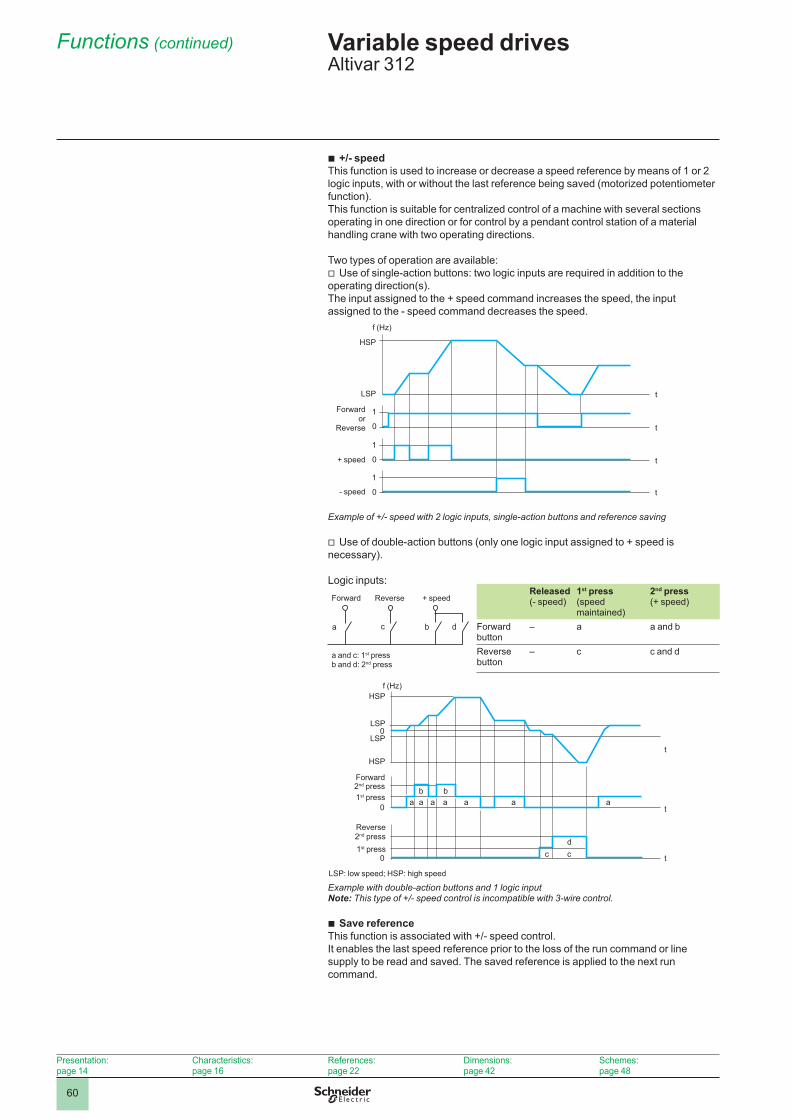
2
1
3
4
5
6
7
8
9
10
2
1
3
4
5
6
7
8
9
10
60
+/- speed This function is used to increase or decrease a speed reference by means of 1 or 2 logic inputs, with or without the last reference being saved (motorized potentiometer function). This function is suitable for centralized control of a machine with several sections operating in one direction or for control by a pendant control station of a material handling crane with two operating directions.
Two types of operation are available:Use of single-action buttons: two logic inputs are required in addition to the
operating direction(s). The input assigned to the + speed command increases the speed, the input assigned to the - speed command decreases the speed.
1
0
1
0
1
0
f (Hz)
t
t
t
t
Forward or
Reverse
+ speed
- speed
HSP
LSP
Example of +/- speed with 2 logic inputs, single-action buttons and reference saving
Use of double-action buttons (only one logic input assigned to + speed is necessary).
Logic inputs:
a c b d
Forward
a and c: 1st pressb and d: 2nd press
Reverse + speedReleased(- speed)
1st press(speed maintained)
2nd press(+ speed)
Forward button
– a a and b
Reverse button
– c c and d
0
0 a ab b
a a a a
c cd
a
0
f (Hz)
t
t
t
2nd press1st press
Reverse 2nd press1st press
HSP
LSP
LSP
HSP
Forward
LSP: low speed; HSP: high speed
Example with double-action buttons and 1 logic inputNote: This type of +/- speed control is incompatible with 3-wire control.
Save referenceThis function is associated with +/- speed control. It enables the last speed reference prior to the loss of the run command or line supply to be read and saved. The saved reference is applied to the next run command.
b
v
v
b
Presentation:page 14
Characteristics:page 16
References:page 22
Dimensions:page 42
Schemes:page 48
Functions (continued) Variable speed drivesAltivar 312
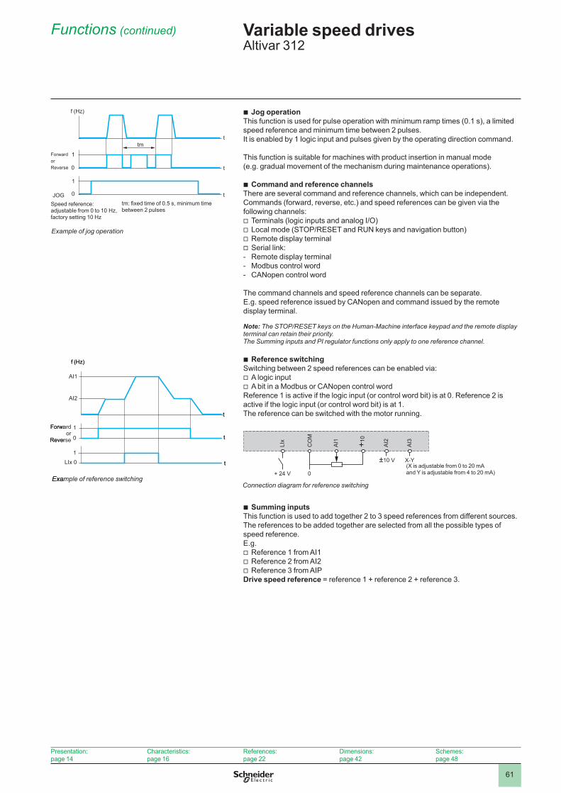
2
1
3
4
5
6
7
8
9
10
2
1
3
4
5
6
7
8
9
10
61
Jog operation This function is used for pulse operation with minimum ramp times (0.1 s), a limited speed reference and minimum time between 2 pulses. It is enabled by 1 logic input and pulses given by the operating direction command.
This function is suitable for machines with product insertion in manual mode(e.g. gradual movement of the mechanism during maintenance operations).
Command and reference channelsThere are several command and reference channels, which can be independent.Commands (forward, reverse, etc.) and speed references can be given via the following channels:
Terminals (logic inputs and analog I/O)Local mode (STOP/RESET and RUN keys and navigation button)Remote display terminalSerial link:Remote display terminalModbus control wordCANopen control word
The command channels and speed reference channels can be separate.E.g. speed reference issued by CANopen and command issued by the remote display terminal.
Note: The STOP/RESET keys on the Human-Machine interface keypad and the remote display terminal can retain their priority. The Summing inputs and PI regulator functions only apply to one reference channel.
Reference switching Switching between 2 speed references can be enabled via:
A logic inputA bit in a Modbus or CANopen control word
Reference 1 is active if the logic input (or control word bit) is at 0. Reference 2 is active if the logic input (or control word bit) is at 1.The reference can be switched with the motor running.
LIx
CO
M
AI1
AI2
AI3
+ 24 V
±10 V X-Y
+10
0
Connection diagram for reference switching
(X is adjustable from 0 to 20 mA and Y is adjustable from 4 to 20 mA)
Summing inputsThis function is used to add together 2 to 3 speed references from different sources.The references to be added together are selected from all the possible types of speed reference.E.g.
Reference 1 from AI1Reference 2 from AI2Reference 3 from AIP
Drive speed reference = reference 1 + reference 2 + reference 3.
b
b
vvvv---
b
vv
b
vvv
1
0
1
AI2
AI1
LIx 0
f (Hz)
t
t
t
Forwardor
Reverse
Example of reference switching
1
0
1
AI2
AI1
LIx 0
f (Hz)
t
t
t
Forwardor
Reverse
Example of reference switching
Presentation:page 14
Characteristics:page 16
References:page 22
Dimensions:page 42
Schemes:page 48
Functions (continued) Variable speed drivesAltivar 312
1
0
1
0
f (Hz)
Forward or Reverse
Speed reference:adjustable from 0 to 10 Hz,factory setting 10 Hz
t
t
ttm
JOGtm: fixed time of 0.5 s, minimum time between 2 pulses
Example of jog operation

2
1
3
4
5
6
7
8
9
10
2
1
3
4
5
6
7
8
9
10
62
PI regulator This function is used for simple control of a flow rate or a pressure with a sensor supplying a feedback signal adapted to the drive. It is suitable for pumping and ventilation applications.
PI reference: Internal regulator reference, adjustable from 0 to 100Regulation reference selected from all the possible types of regulation referencePreset PI references2 or 4 preset PI references adjustable from 0 to 100, require the use of 1 or 2
logic inputs respectivelyManual referenceSpeed reference selected from all the possible types of speed reference PI feedback:
- Analog input AI1, AI2 or AI3Auto/Man:Logic input LI for switching operation to speed reference (Man) or PI regulation
(Auto)During operation in automatic mode, the process feedback can be adapted to correct inverse PI, adjust the proportional and integral gain, or apply a ramp (time = ACC - DEC) for establishing the PI action on starting and stopping.The motor speed is limited to between LSP and HSP.
Note: The PI function is incompatible with the Preset speeds and JOG functions. The PI reference can also be transmitted on line via the Modbus RS 485 serial link or via the CANopen bus.
Current limit switching A second current limit can be configured between 0.25 and 1.5 times the nominal drive current.This function limits the torque and the temperature rise of the motor.Switching between the two current limits can be enabled via:
A logic inputA bit in a Modbus or CANopen control word
Limiting low speed operating timeThe motor is stopped automatically after a period of operation at low speed (LSP) with a zero reference and a run command present.This time can be set between 0.1 and 999.9 seconds (0 corresponds to an unlimited time). Factory setting: 0 s. The motor restarts automatically on the ramp when the reference reappears or if the run command is interrupted and then re-established.This function is suitable for automatic stopping/starting of pressure-regulated pumps.
Motor switchingThis function allows two motors with different powers to be supplied alternately by the same drive. Switching must take place with the drive stopped and locked, using an appropriate sequence at the drive output.The function can be used to adapt the motor parameters. The following parameters are switched automatically:
Nominal motor voltageNominal motor frequencyNominal motor currentNominal motor speedMotor cosine Phi (power factor)Selection of the type of voltage/frequency ratio for motor 2IR compensation, motor 2Motor frequency loop gainMotor stabilityMotor slip compensation
Motor thermal protection is disabled by this function.Motor switching can be enabled by:
A logic inputA bit in a Modbus or CANopen control word
With hoisting applications, this function enables a single drive to be used for vertical and horizontal movements.
b
v---v
v-v
v-
b
vv
b
b
vvvvvvvvvv
vv
ACCDEC
RPGRIG
PICX±1
FBS
+PI reference
PI feedback
Manual reference
ReferenceAuto
Man
PI inversion
PI regulator
Ramp Multiplier
Auto/man
ACC: AccelerationDEC: DecelerationFBS: PI feedback multiplication coefficientHSP: High speedPIC: Reversal of the direction of correction of the PI regulatorLSP: Low speedRIG: PI regulator integral gainRPG: PI regulator proportional gain
PI feedback
HSP
LSP
Presentation:page 14
Characteristics:page 16
References:page 22
Dimensions:page 42
Schemes:page 48
Functions (continued) Variable speed drivesAltivar 312
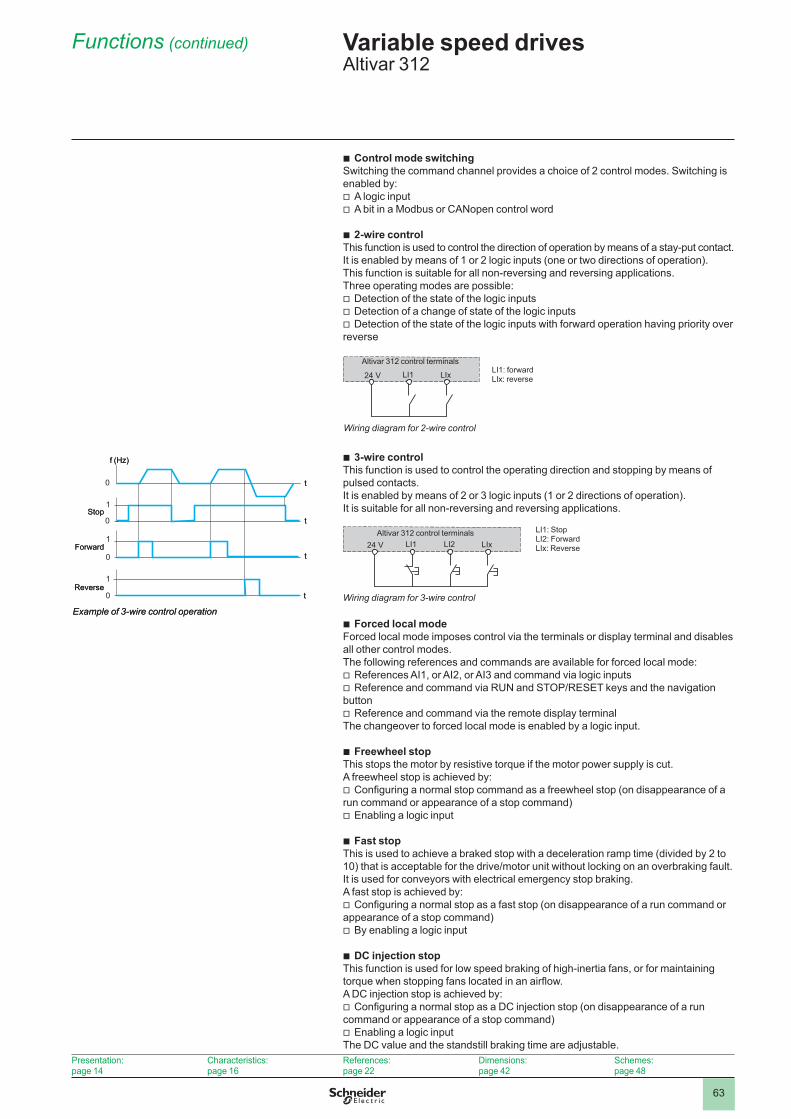
2
1
3
4
5
6
7
8
9
10
2
1
3
4
5
6
7
8
9
10
63
Control mode switchingSwitching the command channel provides a choice of 2 control modes. Switching is enabled by:
A logic inputA bit in a Modbus or CANopen control word
2-wire controlThis function is used to control the direction of operation by means of a stay-put contact.It is enabled by means of 1 or 2 logic inputs (one or two directions of operation).This function is suitable for all non-reversing and reversing applications.Three operating modes are possible:
Detection of the state of the logic inputsDetection of a change of state of the logic inputsDetection of the state of the logic inputs with forward operation having priority over
reverse
24 V LI1 LIx
Altivar 312 control terminalsLI1: forwardLIx: reverse
Wiring diagram for 2-wire control
3-wire control This function is used to control the operating direction and stopping by means of pulsed contacts. It is enabled by means of 2 or 3 logic inputs (1 or 2 directions of operation).It is suitable for all non-reversing and reversing applications.
24 V LI1 LI2 LIxAltivar 312 control terminals LI1: Stop
LI2: ForwardLIx: Reverse
Wiring diagram for 3-wire control
Forced local modeForced local mode imposes control via the terminals or display terminal and disables all other control modes.The following references and commands are available for forced local mode:
References AI1, or AI2, or AI3 and command via logic inputsReference and command via RUN and STOP/RESET keys and the navigation
buttonReference and command via the remote display terminal
The changeover to forced local mode is enabled by a logic input.
Freewheel stop This stops the motor by resistive torque if the motor power supply is cut.A freewheel stop is achieved by:
Configuring a normal stop command as a freewheel stop (on disappearance of a run command or appearance of a stop command)
Enabling a logic input
Fast stopThis is used to achieve a braked stop with a deceleration ramp time (divided by 2 to 10) that is acceptable for the drive/motor unit without locking on an overbraking fault.It is used for conveyors with electrical emergency stop braking.A fast stop is achieved by:
Configuring a normal stop as a fast stop (on disappearance of a run command or appearance of a stop command)
By enabling a logic input
DC injection stopThis function is used for low speed braking of high-inertia fans, or for maintaining torque when stopping fans located in an airflow.A DC injection stop is achieved by:
Configuring a normal stop as a DC injection stop (on disappearance of a run command or appearance of a stop command)
Enabling a logic inputThe DC value and the standstill braking time are adjustable.
b
vv
b
vvv
b
b
vv
v
b
v
v
b
v
v
b
v
v
1
1
1
0
0
0
0
f (Hz)
Stop
Forward
Reverse
t
t
t
t
Example of 3-wire control operation
1
1
1
0
0
0
0
f (Hz)
Stop
Forward
Reverse
t
t
t
t
Example of 3-wire control operation
Presentation:page 14
Characteristics:page 16
References:page 22
Dimensions:page 42
Schemes:page 48
Functions (continued) Variable speed drivesAltivar 312

2
1
3
4
5
6
7
8
9
10
2
1
3
4
5
6
7
8
9
10
64
Brake control This function is used to manage control of an electromagnetic brake in synchronization with starting and stopping the motor to avoid jolts and speed errors.The brake control sequence is managed by the drive.Adjustable values for releasing the brake: current threshold and time delayAdjustable values for engaging the brake: frequency threshold and time delayEnabled by: relay logic output R2 or logic output AOC assigned to brake control.This function is suitable for material handling applications with movements equipped with electromagnetic brakes (hoisting) and machines requiring holding brake control (unbalanced machines).
Principle:Vertical hoisting movement:
Maintains motor torque in an upward direction when the brake is being released and engaged, in order to hold the load and start smoothly as soon as the brake is released.
Horizontal hoisting movement: Synchronizes brake release with the build-up of torque during starting and brake engage at zero speed on stopping, to prevent jolting.The recommended brake control settings for vertical hoisting applications are as follows (for horizontal hoisting applications, set the current threshold to zero):
Brake release current: Set the brake release current to the nominal current indicated on the motor. If, during testing, the torque is insufficient, increase the brake release current (the maximum value is imposed by the drive).
Acceleration time: For hoisting applications it is advisable to set the acceleration ramps to more than 0.5 seconds. Ensure that the drive does not change to current limiting.The same recommendation applies for deceleration.Note: For a hoisting movement, a braking resistor should be used. Ensure that the selected settings and configurations will not result in dropping or loss of control of the load being lifted.
Brake release time delay t1: Adjust according to the type of brake. It is the time required for the mechanical brake to release.
Brake engage frequency: Set to twice the nominal slip, then adjust according to the result.
Brake engage time delay t2: Adjust according to the type of brake. It is the time required for the mechanical brake to engage.
Limit switch managementThis function is used to manage the operation of one or two limit switches (with 1 or 2 operating directions).Each limit (forward, reverse) is associated with a logic input. The type of stop that occurs on detection of a limit is configurable as normal, freewheel or fast stop.Following a stop, the motor is permitted to restart in the opposite direction only.
Monitoring The following data can be displayed:
Frequency referenceInternal PI referenceFrequency reference (absolute value)Output frequency applied to the motor (value signed in two’s complement)Output frequency in customer unitsCurrent in the motorMotor power: 100% = nominal powerLine voltageMotor thermal state:100%: nominal thermal state, 118%: motor overload thresholdDrive thermal state:100%: nominal thermal state, 118%: drive overload thresholdMotor torque: 100% = nominal torqueLast detected faultOperating timeAuto-tuning statusConfiguration and state of logic inputsConfiguration of analog inputs
b
v-
-
-
-
-
-
-
b
b
vvvvvvvvv-v-vvvvvv
0
0
1
0
1
0
0
Speed reference
t
t
t
t
Accessible settings:t1: brake release time delayt2: brake engage time delay
Relay or logic output
Motor current
t
Brake release current
Speed referenceBrake engage frequency
LI forward or reverse
T
t1
t2
State of brake Engaged Released Engaged
Brake control
0
0
1
0
1
0
0
Speed reference
t
t
t
t
Accessible settings:t1: brake release time delayt2: brake engage time delay
Relay or logic output
Motor current
t
Brake release current
Speed referenceBrake engage frequency
LI forward or reverse
T
t1
t2
State of brake Engaged Released Engaged
Brake control
Presentation:page 14
Characteristics:page 16
References:page 22
Dimensions:page 42
Schemes:page 48
Functions (continued) Variable speed drivesAltivar 312
2
1
3
4
5
6
7
8
9
10
2
1
3
4
5
6
7
8
9
10
65
Fault management There are various operating modes in the event of resettable faults:
Freewheel stopThe drive switches to the fallback speedThe drive maintains the speed at which it was operating when the fault occurred,
until the fault disappearsStop on rampFast stop
The following resettable faults are detected:Drive overheatingMotor overheatingCANopen bus faultModbus serial link failureExternal faultsLoss of 4-20 mA signal
Fault reset This function is used to clear the last fault by means of a logic input. The restart conditions after a reset are the same as those for a normal power-up.Resets the following faults: overvoltage, overspeed, external fault, drive overheating, output phase loss, DC bus overvoltage, loss of 4-20 mA reference, load slipping, motor overload if the thermal state is less than 100%, serial link fault.Line supply undervoltage and input phase loss faults are reset automatically when the line supply is restored.This function is suitable for applications where the drives are difficult to access, for example on moving parts or in material handling systems.
General reset (disables all faults)This function disables all faults, including thermal protection (forced operation), and can result in irreparable damage to the drive.This invalidates the warranty.
This function is suitable for applications where restarting may be crucial (conveyor in an oven, smoke extraction system, machines with solidifying products that need to be removed).The function is enabled by a logic input.Fault monitoring is active if the logic input is at state 1.All faults are reset on a change of state of the logic input.
Controlled stop on loss of line supplyThis function is used to control motor stopping on a loss of line supply.It is suitable for material handling, machines with high inertia, continuous product processing machines.Possible types of stop:
Locking of the drive and freewheel stopStop which uses the mechanical inertia to maintain the drive power supply as long
as possibleStop on rampFast stop (depends on the inertia and the braking ability of the drive)
Stop mode in the event of a faultThe type of stop that occurs on detection of a fault is configurable as normal, freewheel or fast for the following faults:
External fault (detection enabled by a logic input or a bit in a Modbus or CANopen control word)
Motor phase loss faultIf an output contactor is being used between the drive and the motor, the motor phase loss fault should be disabled.
b
vvv
vv
vvvvvv
b
b
b
vv
vv
b
v
v
Presentation:page 14
Characteristics:page 16
References:page 22
Dimensions:page 42
Schemes:page 48
Functions (continued) Variable speed drivesAltivar 312

2
1
3
4
5
6
7
8
9
10
2
1
3
4
5
6
7
8
9
10
66
Automatic catching of a spinning load with speed detection (“catch on the fly”)This function is used to restart the motor smoothly after one of the following events, provided the run command is still present:
Loss of line supply or power offFault reset or automatic restartFreewheel stop
On disappearance of the event, the rms speed of the motor is detected in order to restart on a ramp from this speed and return to the reference speed. Speed detection can take up to 1 s depending on the initial deviation.This function is automatically disabled if the brake sequence is configured.It is suitable for machines for which the motor speed loss is negligible during the loss of line supply (such as machines with high inertia, fans and pumps driven by a residual flow, etc.).
Automatic restartThis function enables the drive to be restarted automatically after it has locked in fault mode, provided the fault has disappeared and the other operating conditions permit a restart.This restart is performed by a series of automatic attempts separated by increasingly longer waiting periods of 1 s, 5 s, 10 s, then 1 minute for subsequent periods.The restart procedure can last between 5 minutes and an unlimited time.If the drive has not restarted after the configured time, it will lock and the procedure is abandoned until it has been powered off and on again.
The faults which permit this type of restart are:Line overvoltageMotor thermal overloadDrive thermal overloadDC bus overvoltageLoss of one input phaseExternal faultLoss of 4-20 mA referenceCANopen bus faultModbus serial link faultLine voltage too low. For this fault, the function is always active, even if it is not
configured.For these faults, the relay configured as a fault relay remains activated if the function is configured. The speed reference and direction of operation must be maintained for this function.This function is suitable for machines or installations which are in continuous operation or are not monitored, and where a restart will not endanger equipment or personnel in any way.
Derated operation in the event of an undervoltageThe line voltage monitoring threshold is lowered to 50% of the motor voltage.In this case, a line choke must be used and the performance of the drive cannot be guaranteed.
Fault relay, unlocking The fault relay is energized when the drive is powered up and is not faulty.It contains an N/C contact and an N/O contact with common point.The drive is unlocked after a fault in one of the following ways:
By powering down until the ON LED goes out, then switching the drive back onBy assigning a logic input to the External faults functionBy the Automatic restart function, if it has been configured
Resetting operating time to zeroThe drive operating time can be reset to zero.
b
vvv
b
vvvvvvvvvv
b
b
vvv
b
Presentation:page 14
Characteristics:page 16
References:page 22
Dimensions:page 42
Schemes:page 48
Functions (continued) Variable speed drivesAltivar 312

2
1
3
4
5
6
7
8
9
10
2
1
3
4
5
6
7
8
9
10
67
Motor thermal protection The theoretical temperature rise of the motor is continuously calculated to provide indirect thermal protection.Thermal protection is adjustable from 0.2 to 1.5 times the nominal drive current.This function is suitable for all applications with self-cooled motors.
10 000( 2 h 45)
1 000
1000,7 0,8 0,9 1 1,1 1,2 1,3 1,4 1,5 1,6
5020101 3 5 Hz
( 16 mn)
Motor thermal protection curvesMotor current/ItH
t
Trip
tim
e in
sec
onds
Drive thermal protectionThermal protection, by a PTC probe mounted on the heatsink or integrated in the power module, ensures that the drive is protected in the event of poor ventilation or excessive ambient temperatures.Locks the drive in the event of a fault.
5000
3000
1000
200
160
100
60
20 1 1,1 1,2 1,3 1,4 1,5 1,6 1,7 1,8 1,9
t
Motor current/Drive In
Trip
tim
e in
sec
onds
Drive thermal protection curves
R1/R2 relay configurationThe following states are signalled when the relay is powered on:
Drive faultDrive runningFrequency threshold reachedHigh speed reachedCurrent threshold reachedFrequency reference reachedMotor thermal threshold reachedBrake sequence (R2 only)
b
b
b
vvvvvvvv
Presentation:page 14
Characteristics:page 16
References:page 22
Dimensions:page 42
Schemes:page 48
Functions (continued) Variable speed drivesAltivar 312

2
1
3
4
5
6
7
8
9
10
2
1
3
4
5
6
7
8
9
10
68
AOC/AOV analog outputs The same data is available on analog outputs AOC and AOV. The following assignments are possible:
Motor currentMotor frequencyMotor torquePower supplied by the driveDrive faultFrequency threshold reachedHigh speed reachedCurrent threshold reachedFrequency reference reachedMotor thermal threshold reachedBrake sequence
Adjusting analog outputs AOC/AOV modifies the characteristics of the current analog output AOC or the voltage analog output AOV.AOC: can be set as 0-20 mA or 4-20 mAAOV: can be set as 0-10 V
Saving and retrieving the configurationIt is possible to save a configuration. This function is used to store a drive configuration in addition to the current configuration.Retrieving this configuration clears the current configuration.
b
vvvvvvvvvvv
b
Presentation:page 14
Characteristics:page 16
References:page 22
Dimensions:page 42
Schemes:page 48
Functions (continued) Variable speed drivesAltivar 312

2
1
3
4
5
6
7
8
9
10
2
1
3
4
5
6
7
8
9
10
69
Function compatibility tableConfigurable I/O
Functions which are not listed in this table are fully compatible.Stop functions have priority over run commands.The selection of functions is limited by:
The number of drive I/OThe incompatibility of certain functions with one another
b
--
Functions Summing inputs
+/- speed Limit switch management
Preset speeds
PI regulator
Jog operation
Brake sequence
DC injection stop
Fast stop Freewheel stop
Summing inputsA A
+/- speed
Limit switch management
Preset speedsX A
PI regulator
Jog operationX X
Brake sequence
DC injection stopA
Fast stopA
Freewheel stop X X
Incompatible functions Priority functions (functions which cannot be active at the same time)
Compatible functions X The arrow indicates which function has priority
Not applicable A Example: the Freewheel stop function has priority over the Fast stop function
Presentation:page 14
Characteristics:page 16
References:page 22
Dimensions:page 42
Schemes:page 48
Functions (continued) Variable speed drivesAltivar 312

September 2009 - V2.0
DIA
2ED
2090
404E
N
ART. 960364
The information provided in this documentation contains general descriptions and/or technical characteristics of the performance of the products contained herein. This documentation is not intended as a substitute for and is not to be used for determining suitability or reliability of these products for specifi c user applications. It is the duty of any such user or integrator to perform the appropriate and complete risk analysis, evaluation and testing of the products with respect to the relevant specifi c application or use thereof. Neither Schneider Electric nor any of its affi liates or subsidiaries shall be responsible or liable for misuse of the information contained herein.
Design: Schneider ElectricPhotos: Schneider ElectricPrinted by:
Head Offi ce35, rue Joseph MonierF-92500 Rueil-MalmaisonFrance
Schneider Electric Industries SAS www.schneider-electric.com


![3DBGMHB@K RODBHjB@SHNM - Electrikastorage.electrika.com/manu/man-6090/pdftech/6090-havells-pwr-13...Starting current [mA] < 20 < 2 ... Glow wire test According to IEC 60 695-2-1 According](https://img.dokumen.tips/doc/110x75/5aa2a1bb7f8b9a436d8d3563/3dbgmhbk-rodbhjbshnm-current-ma-20-2-glow-wire-test-according-to-iec-60.jpg)