Embed Size (px)
Citation preview

Flow
Dew Point
Chart recorder
Pressure
Leakage
Compressed air quality
Current
Software
CS INSTRUMENTS
Proven and innovative measuring
technology for compressed air and gases
Catalogue 2020

OVERVIEW CHART RECORDER
DS 500
Page 10-13
DS 400
Page 14-17
DS 500 mobile
Page 22-25
DS 400 mobile
Page 26-29
PI 500
Page 30-31
• Chart recorder for data logging of up to 2/4 sensors
• 3.5" colour screen with touch panel
• Option:Ethernet connection• Option: 8 GB data memory
• Chart recorder for data logging of up to 2/4 sensors
• 3.5" colour screen with touch panel
• use
• Integrated Li-Ion battery• Ethernet connection• 8 GB data memory
• Chart recorder for data logging of up to 4/8/12 sensors
• 7" colour screen with touch panel
• Ethernet connection• 8 GB data memory
• Chart recorder for data logging of up to 4/8/12 sensors
• 7" colour screen with touch panel
• use
• Ethernet connection• 8 GB data memory
• Portable handheld device• 1 sensor input• 3.5" colour screen with touch
panel• Integrated Li-Ion battery• 8 GB data memory
Sensors for DS 500 / DS 400Pressure TemperatureCurrent
Sensors for mobile devices
Page 18-20 Page 32-35
Pressure Current Temperature
2 www.cs-instruments.com

OVERVIEW DEW POINT
DP 500/510
Page 40-41
DS 400 mobile
Page 42-43
FA 510/515
Page 44
DS 52
Page 45
FA 515 EX
Page 46
FA 550
Page 48-49
FA 500
Page 50-51
DS 400
Page 52-53
• Mobile dew point device• Meas. range -80...+50 °Ctd pres-
sure dew point• 3.5" colour screen with touch
panel• Integrated Li-Ion battery• 8 GB data memory
• Mobile dew point device in a sturdy service case
• Integrated pressure measure-ment up to 16 bar
• Meas. range -80...+50 °Ctd pres-sure dew point, ppm, atmospher-ic dew point, etc...
• Integrated Li-Ion battery
• Dew point sensor for residual moisture measurement in com-pressed air and gases
• Measuring range: -80…+20 °Ctd or -20…+50 °Ctd
• 4...20 mA analogue output and/or Modbus-RTU
• Plug-in dew point set• Measuring range: -80…
+20 °Ctd or -20…+50 °Ctd• 2 alarm relays (freely adjust-
able)• 4...20 mA analogue output
• Dew point sensor for residual moisture measurement in compressed air and gases in potentially explosive atmo-spheres
• Meas. range -80...+20 °Ctd• Approvals: Zone 1: Gas Zone
21: Dust• 4...20 mA analogue output
• Dew point sensor with a sturdy die-cast aluminium housing
• IP 67, suitable for outdoor use• 2x 4…20 mA analogue output
and Modbus-RTU• Option: Ethernet interface
• Dew point sensor with integrat-ed display
• Measuring range: -80…+20 °Ctd or -20…+50 °Ctd
• 4...20 mA analogue output and Modbus-RTU
• Option: Ethernet interface
• Plug-in dew point set• Option: integrated data logger
dew point monitoring• Option: Ethernet interface• 3.5" colour screen with touch
panel
Page 54-60Accessories for dew point measurement / calibration
www.cs-instruments.com 3

OVERVIEW FLOW
VA 570
Page 66-70
VA 570
Page 66-70
VA 550
Page 72-75
VA 500
Page 76-77
VA 520
Page 78-79
VA 520
Page 80-81
VA 521
Page 82-83
• • Sturdy die-cast aluminium
housing IP 67• Option with ATEX or DVGW
approval• All wetted parts of stainless
steel• DN 15 to DN 80
• • Sturdy die-cast aluminium
housing IP 67• Option with ATEX or DVGW
approval• All wetted parts of stainless
steel• 1/2" to 2"
• version
• Easy installation and removal under pressure without line interruption
• Applicable in existing pipes from 3/4" to DN 1000
• Option with ATEX or DVGW ap-proval
• All wetted parts of stainless steel
• Flow meter as an insertion version
• Easy installation and removal under pressure without line interruption
• Applicable in existing pipes from 1/2" to DN 1000
• Option: Bi-directional measure-ment
• • DN 15 to DN 80• Option: Bi-directional measure-
ment
• • 1/4" to 2"
• • No inlet section necessary –
• Sensor unit removable• 1/4" to 2"
Page 88-95Accessories for Consumption Measurement / Calibration /
VA 525
Page 84-85
• air and nitrogen
• No inlet section necessary –
• 1/4" to 2"
4 www.cs-instruments.com

OVERVIEW COMPRESSED AIR QUALITY
Oil-Check 400 / PC 400 / FA 510
Page 109
Oil-Check 400 - stationary solution
Page 110-111 Page 111
PC 400/DS 400 - stationary solution
Page 112-113
Oil-Check 400 - stationary solution
PC 400 / DS 500 mobile solution
Page 113
• Measure compressed air quality according to ISO 8573
• Residual oil - particles - residual moisture
• Mobile solution
• Monitoring system for residual oil content measurement in compressed air
• Monitoring system for residual oil content measurement in compressed air
• With handle and stand plus
• Monitoring system for particle measurement in compressed air
• Monitoring system for particle measurement in compressed air
• PC 400 in a service case• DS 500 mobile in a sturdy
service case
Oil-Check 400 / PC 400 / FA 510• Measure compressed air quality
according to ISO 8573• Residual oil - particles - residual
moisture• Stationary solution
Page 108-109
www.cs-instruments.com 5

OVERVIEW LEAKAGE
LD 500/510
Page 114-118
LD 400
Page 120-121
CS Leak Reporter
Page 117
• Leak detector with camera• Shows leakage rate in l/min and
costs in euros• USB interface for data transfer
into the evaluation software CS Leak Reporter
• Special accessories
• Low-price leak detector
• Creates detailed ISO 50001 reports• Provides an illustrated overview of
the leakages found and their savings potential
6 www.cs-instruments.com

OVERVIEW SOFTWARE
CS Basic
Page 122-125
CS Network
Page 126-127
• Data evaluation as a graph or in table form
• Reading the measurement data of all CS Instruments data loggers / chart recorders via USB or Ethernet
• Energy monitoring software with Client/Server solution
• Automatically collects the measured values of all CS devices in the network on servers
• Evaluation / analysis at any number of workplaces (Client)
www.cs-instruments.com 7

8 www.cs-instruments.com8
Overview
Compressed air quality ISO 8573-1• Dew point (page 44-53)
• Residual oil (page 108-113)
• Particles (page 108-113)
• Electrical power measurement (page 20)
• Compressor capacity (page 86)
• Data logger / chart recorder (page 10-31)
• CS Basic Software (page 122-127)

9www.cs-instruments.com 9
Overview
• Insertion version (page 76-77)
• Inline version (page 78-81)
• Compact version (page 82-85)
• CS Network Software (page 122-127)
Leak detection• Leak detector with camera - shows leakage rate in l/min and costs in €
(page 114-118)
• CS Leak Reporter Software - creates detailed ISO 50001 reports (page 117)

DS 500 - Intelligent chart recorder for compressed air and gasesMeasurement - control - indication - alarm - recording - evaluation
Advantages at a glance:
• Clear layout: 7" colour screen with touch panel...
• Versatile:Up to 12 optional sensors can be connected
• Suitable for industrial applications: Metal housing IP 65 or panel mounting...
• Data available through world wide web: Net-work-compatible and remote transmission via web-server
• Mathematical function: for internal calculations
• Totaliser function: for analogueue signals
• ...saves time and costs during installation
DS 500 - the intelligent chart recorder of the next generation
Recording of the measured data, indication on a big colour screen, alerting, storage, not to mention remote read-out via webserver... this is all possible with DS 500.
All measured values, measurement curves and threshold value exceedances are indicated. The curve progressions from the beginning of the measurement can be viewed by an easy slide of the finger.
The big difference to ordinary paperless chart recorders reveals in the easy initiation and in the evaluation of the measured data. All sen-sors are identified directly and powered by DS 500. Everything is matched and tuned.
Mathematical function for internal calculations, e.g. the typical figures of a compressed air system:
• costs in € per generated m³ air
• kWh/m³ generated air
• consumption of single lines including summation
Totaliser function for analogueue signals (e.g. 0/4…20 mA, 0…10 V). In case of third-party sensors which e.g. only give a 4...20 mA signal for the actual flow in m³/h, a total counter reading in m³ can be generated by means of the totaliser function.
No time consuming studying of the instruction manual... this saves time. Internal voltage supply of all sensors, no wiring of external mains units ... this saves additional costs.
www.cs-instruments.com10
Chart recorder
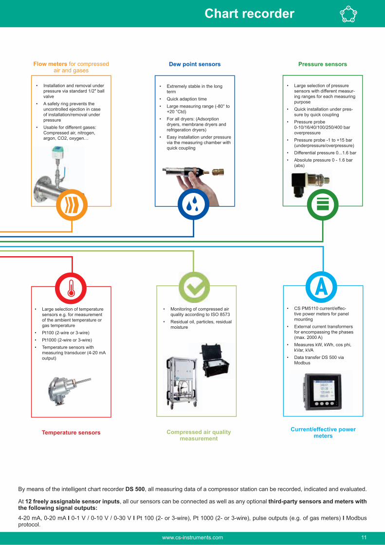
• CS PM5110 current/effec-tive power meters for panel mounting
• External current transformers for encompassing the phases (max. 2000 A)
• Measures kW, kWh, cos phi, kVar, kVA
• Data transfer DS 500 via Modbus
Flow meters for compressed air and gases
Dew point sensors Pressure sensors
By means of the intelligent chart recorder DS 500, all measuring data of a compressor station can be recorded, indicated and evaluated.
At 12 freely assignable sensor inputs, all our sensors can be connected as well as any optional third-party sensors and meters with the following signal outputs:4-20 mA, 0-20 mA I 0-1 V / 0-10 V / 0-30 V I Pt 100 (2- or 3-wire), Pt 1000 (2- or 3-wire), pulse outputs (e.g. of gas meters) I Modbus protocol.
Current/effective power meters
• Installation and removal under pressure via standard 1/2" ball valve
• A safety ring prevents the uncontrolled ejection in case of installation/removal under pressure
• Usable for different gases: Compressed air, nitrogen, argon, CO2, oxygen…
• Extremely stable in the long term
• Quick adaption time• Large measuring range (-80° to
+20 °Ctd)• For all dryers: (Adsorption
dryers, membrane dryers and refrigeration dryers)
• Easy installation under pressure via the measuring chamber with quick coupling
• Large selection of pressure sensors with different measur-ing ranges for each measuring purpose
• Quick installation under pres-sure by quick coupling
• Pressure probe 0-10/16/40/100/250/400 bar overpressure
• Pressure probe -1 to +15 bar (underpressure/overpressure)
• Differential pressure 0...1.6 bar• Absolute pressure 0 - 1.6 bar
(abs)
Compressed air quality measurement
• Monitoring of compressed air quality according to ISO 8573
• Residual oil, particles, residual moisture
• Large selection of temperature sensors e.g. for measurement of the ambient temperature or gas temperature
• Pt100 (2-wire or 3-wire)• Pt1000 (2-wire or 3-wire)• Temperature sensors with
measuring transducer (4-20 mA output)
Temperature sensors
www.cs-instruments.com 11
Chart recorder

Actual measured valuesAll measured values can be seen at a glance.Threshold value exceedances are indicated in red color.A „measuring site name“ can be allocated to each sensor.
Graphic displayThis display replaces the former evaluation of ordinary paper chart recorders and offers lots of advantages. The time axis can be moved by a finger slide.The „zoom function by finger movement“ which enables an analysis of peak values is unique.
Actual measured values and graphicAdditionally to the measurement curves, the current measured values are indicated as well.
Measured values, statistics, curves with the 7" colour screen with touch panel
Adjustment of the alarm relaysEach one of the four alarm relays can be allocated individually to a connected sensor. The alarm thresholds and the hystere-sis can be freely adjusted.New: It is possible to set an alarm delay for each alarm relay so that the relay is only triggered after that period of time.
www.cs-instruments.com12
Chart recorder

INPUT SIGNALSCurrent signalsInternal or external power supplyMeasuring rangeResolutionAccuracyInput resistance
(0…20 mA/ 4…20 mA)
0…20 mA0.0001 mA± 0.03 mA ± 0.05 %
Voltage signal:Measuring rangeResolutionAccuracyInput resistance
(0…1 V)0…1 V0.05 mV± 0.2 mV ± 0.05 %
Voltage signalMeasuring rangeResolutionAccuracyInput resistance
(0...10 V / 30 V)0…10 V0.5 mV± 2 mV ± 0.05 %
RTD Pt 100Measuring rangeResolutionAccuracy
-200…850 °C0.1 °C± 0.2 °C (-100…400 °C)± 0.3 °C (further range)
RTD Pt 1000Measuring rangeResolutionAccuracy
-200…850 °C0.1 °C± 0.2° (-100…400 °C)
PulseMeasuring range
Min pulse length 500 μs frequency 0...1 kHzmax. 30 VDC
Technical data of the DS 500
Matching sensors can be found on pages 18 to 20
TECHNICAL DATA DS 500Dimensions of housing: 280 x 170 x 90 mm, IP 65
Connections: 18 x PG for sensors and supply
Version panel mounting: Cutout panel 250 x 156 mm
Weight: 7.3 kg
Material: Die cast metal, front screen polyester
Sensor inputs: • 4/8/12 sensor inputs for analogueue and digital sensors; freely allocatable. See options• Digital CS sensors for dew point and consumption with SDI interface FA/VA series,• digital third-party sensors RS 485 / Modbus RTU, other bus systems realizable on request.• • Analogue third-party sensors 0/4...20 mA, 0...1/10/30 V, pulse, Pt 100 / Pt 1000, KTY
Voltage supply for sensor: 24 VDC, max. 130 mA per sensor, integrated mains unit max. 24 VDC, 25 W. In case of version 8/12 sensor inputs, 2 integrated mains units each max. 24 VDC, 25 W.
Interfaces: USB stick, Ethernet / RS 485 Modbus-RTU / TCP, SDI other bus systems on request, webserver optional
Outputs: • 4 relays (changeover contact 230 VAC, 6 A), alarm management, relays freely programmable, collective alarm• Analog output, pulse in case of sensors with own signal output looped, such as e.g. VA/FA series
Memory card: Memory size 8 GB Micro SD card
Power supply: 100...240 VAC / 50-60 Hz, special version 24 VDC
Colour screen: 7" touch panel TFT transmissive, graphics, curves, statistics
Accuracy:Operating temperature: 0…50 °C
Storage temperature: -20…70 °C
Optional: Web server
DESCRIPTION ORDER NO.DS 500 - intelligent chart recorder in basic version (4 sensor inputs) 0500 5000
Option: 4 additional sensor inputs for DS 500 V2 Z500 5501
Option: 8 additional sensor inputs for DS 500 V2 Z500 5502
Option: Integrated webserver Z500 5003
Option: version for panel mounting Z500 5006
Option: Power supply 24 VDC (instead of 100…240 VAC) Z500 5007
Option: “Mathematics calculation function” for 4 freely selectable channels, (virtual channels): addition, subtraction, division, multiplication
Z500 5008
Option: “Totaliser function for analogue signals” Z500 5009
Z500 3008
CS Basic – data evaluation graphically and in tabular form - reading of themeasured data via USB or Ethernet, license for 2 workstations
0554 8040
CS Network – energy monitoring with client/server solution 0554 8041
CS Network – energy monitoring with client/server solution 0554 8042
CS Network – energy monitoring with client/server solution 0554 8043
CS Network - Energy Monitoring with Client / Server Solution 0554 8044
www.cs-instruments.com 13
Chart recorder

DS 400 - Chart recorderfor all relevant parameters of compressed air
Software options:
• Integrated webserver
• Mathematics calculation function
• Totaliser function
Hardware options:
• Integrated data logger
• Ethernet / RS 485 interface
• Additional sensor inputs (digital or analogueue) selectable
Standard equipment:• USB interface
• 3.5" graphic display with touch screen
• Integrated mains unit for supply of the sensors
• 4...20 mA analogue output of all connected active sensors
• -sors
• 2 alarm relays (pot.-free changeover contacts, max. 230 V, 3 A)
Digital Digital Digital Digital
m³/h, m³ °Ctd A, kWh
Flow sensor Dew point sensor
Current/effective
power meter
Third-party sensors
with RS 485
Digital Analogue Analogue Analogue Analogue
bar A °C °C
Pressure sensor Clamp-on ammeter
Temperature sensor
Third party sensor
analogue output
4…20 mA0…20 mA0…10 VPulsePt 100Pt 1000
MOD-BUS
The sensor inputs 1 and 2 and 3 and 4 can be selected according to the required sensors
www.cs-instruments.com14
Chart recorder

TECHNICAL DS 400Dimensions: 118 x 115 x 98 mm
IP 54 (wall housing)92 x 92 x 75 mm(panel mounting)
Inputs: 2 digital inputs for FA 5xx resp. VA 5xx
Interface: USB interface
Power supply: 100…240 VAC, 50-60 Hz
Accuracy: -tions
Alarm outputs: 2 relays, (pot.-free)
Options:Data logger: 100 million measured
values start/stop time, measuring rate freely adjustable
2 additional sen-sor inputs:
For connection of pres-sure sensors, tempera-ture sensors, clamp-on ammeters, third-party sensors with 4...20 mA, 0 to 10 V, Pt 100, Pt 1000
INPUT SIGNALSCurrent signalsinternal or external power supplyMeasuring rangeResolutionAccuracyInput resistance
(0…20 mA/4…20 mA)
0…20 mA0.0001 mA± 0.03 mA ± 0.05 %
Voltage signal:Measuring rangeResolutionAccuracyInput resistance
(0…1 V)0…1 V0.05 mV± 0.2 mV ± 0.05 %
Voltage signalMeasuring rangeResolutionAccuracyInput resistance
(0...10 V / 30 V)0…10 V0.5 mV± 2 mV ± 0.05 %
RTD Pt 100Measuring rangeResolutionAccuracy
-200…850 °C0.1 °C± 0.2 °C (-100…400 °C)± 0.3 °C (further range)
RTD Pt 1000Measuring rangeResolutionAccuracy
-200…850 °C0.1 °C± 0.2° (-100…400 °C)
PulseMeasuring range
Min pulse length 500 μs frequency 0...1 kHzmax. 30 VDC
DESCRIPTION ORDER NO.
DS 400 - Chart recorder with graphic display and touch screen
Sensor input 1+2 Sensor input 3+4
Digital (Z500 4003) -------- 0500 4000 D
Digital (Z500 4003) Digital (Z500 4003) 0500 4000 DD
Digital (Z500 4003) Analogue (Z500 4001) 0500 4000 DA
Analogue (Z500 4001) -------- 0500 4000 A
Analogue (Z500 4001) Analogue (Z500 4001) 0500 4000 AA
Options:Option: Integrated data logger for 100 million measured values Z500 4002
Option: Integrated Ethernet and RS 485 interface Z500 4004
Option: Integrated webserver Z500 4005
Option: “Mathematics calculation function” for 4 freely selectable channels, (virtual channels): addition, subtraction, division, multiplication
Z500 4007
Option: “Totaliser function for analogue signals” Z500 4006
Z500 3008
Further accessories:CS Basic – data evaluation graphically and in tabular form - reading of the measured data via USB or Ethernet, license for 2 workstations
0554 8040
CS Network – energy monitoring with client/server solution (max. 20 mea- 0554 8041
CS Network – energy monitoring with client/server solution (max. 50 mea- 0554 8042
CS Network – energy monitoring with client/server solution (max. 100 mea- 0554 8043
CS Network - Energy Monitoring with Client / Server Solution 0554 8044
Back view
Panel mounting
www.cs-instruments.com 15
Chart recorder

In the menu of the DS 500 / DS 400, the flow sensor VA 5xx can be set to the respective pipe inside diame-ter. Furthermore, the unit, the gas type and the reference condition can be set. The meter reading can be set to “zero” if necessary.
Graphic viewIn the graphic view all measured values are indicated as curves. It is possible to browse back on the time axis by a slide of the finger (without data logger maximum 24 h, with data logger back to the start of the measurement).
Data loggerWith the option „integrated data logger“ the measured values are stored in the DS 500 / DS 400. The time interval can be freely set. Furthermore there is the possibility to fix the starting time and the end time of the data recording. Read-out of the measured data via USB interface or via the optional Ethernet interface.
Selection of the languageDS 500 / DS 400 “speaks” several languages. The desired lan-guage can be selected via the selection button.
All relevant parameters at a glanceIn addition to the flow rate in m³ / h, the DS 500 / DS 400 also displays other parameters such as total consumption in m³ and speed in m/s.
DS 500 / DS 400Easy operation via touchscreen:
www.cs-instruments.com16
Chart recorder

Web server The new webserver with substantially extended features for the chart recorders DS 500 and DS 400 is available with immediate effect. Users can thereby get direct access to their measured data worldwide (current and historic ones) and dis-play them on their smart phone, tablet or computer.
The new webserver can be ordered as an option with each stationary DS 500/400, but also for their mobile devices. For using the features of the webservers, the DS 500/400 must be set up with it’s own IP address within the corporate network.
The web server in the DS 500/400 provides a website, which displays the measured values. This website can be accessed from smartphones, tablets and computers via the respectively installed browser. Advantage: This is all possible without the installation of any new or additional software.
View of the real time measured values View of the historic measured values as a single chart
Access authorizationDifferent groups with different users/passwords can be assigned to different access levels.
Starting the data loggerIn case of a stopped data logger the group operator or administrator can start the data logger remotely, via the web server.
PS: The new webserver can be retrofitted to any DS 500/DS 400 already in use.
www.cs-instruments.com 17
Chart recorder

Suitable sensors for DS 500 / DS 400
FLOW METERS INSERTION-VERSION ORDER NO.VA 500 meter in basic version:Standard (92.7 m/s), probe length 220 mm, without display
0695 5001
VA 550 Flow meter, measuring head in robust aluminium die casting housing 0695 0550+ order code A_…M…_
FLOW METERS IN-LINE VERSION ORDER NO.Flow meter VA 520 with integrated measuring section, (R 1/4" DN 8) 0695 0520
Flow meter VA 520 with integrated measuring section, (R 1/2" DN 15) 0695 0521
Flow meter VA 520 with integrated measuring section, (R 3/4" DN 20) 0695 0522
Flow meter VA 520 with integrated measuring section, (R 1" DN 25) 0695 0523
Flow meter VA 520 with integrated measuring section, (R 1 1/4" DN 32) 0695 0526
Flow meter VA 520 with integrated measuring section, (R 1 1/2" DN 40) 0695 0524
Flow meter VA 520 with integrated measuring section, (R 2" DN 50) 0695 0525
Inline Flow meter VA 570 with integrated 1/2"measuring section 0695 0570+ order code A_...K_
Flow meter VA 570 with integrated 3/4" measuring section 0695 0571
Flow meter VA 570 with integrated 1" measuring section 0695 0572
Flow meter VA 570 with integrated 1 1/4" measuring section 0695 0573
Flow meter VA 570 with integrated 1 1/2" measuring section 0695 0574
Flow meter VA 570 with integrated 2" measuring section 0695 0575
Inline flow meter
DEW POINT SENSORS ORDER NO.0699 05100699 0512
Standard measuring chamber for compressed air up to 16 bar 0699 3390
CONNECTION CABLES FOR FLOW METERS/DEW POINT SENSORS VA 500, 520 AND FA 510
ORDER NO.
Connection cable for VA/FA series, 5 m 0553 0104Connection cable for VA/FA sensors, 10 m 0553 0105
CONNECTION CABLES FOR FLOW METERS VA 550/570: ORDER NO.Connection cable 5 m with open ends 0553 0108Connection cable 10 m with open ends 0553 0109
VA 500 VA 550
VA 520
VA 570
FA 510
www.cs-instruments.com18
Chart recorder

PRESSURE PROBES ± 1% ACCU-RACY
± 0,5% ACCU-RACY
Standard pressure probe CS 16, 0...16 bar 0694 1886 0694 3555
Standard pressure probe CS 40, 0…40 bar 0694 0356 0694 3930Standard pressure probe CS 1.6, 0...1.6 bar abs. 0694 3550Standard pressure probe CS 10, 0…10 bar 0694 3556 0694 3554
Standard pressure probe CS 100, 0…100 bar 0694 3557Standard pressure probe CS 250, 0…250 bar 0694 3558Standard pressure probe CS 400, 0…400 bar 0694 3559Precision pressure probe CS -1...+15 bar, ± 0.5 % accuracy of. f.s.
0694 3553
0694 3561
whole measuring range3200 0004
TEMPERATURE SENSORS ORDER NO.Screw-in temperature sensor PT 100 class A, length 300 mm, d = 6 mm, with measuring transducer 4...20 mA = -50 °C...+ 500 °C (2-wire)
0604 0201
Outdoor temperature sensor PT 100 class B (2-wire) in wall housing (82x55x33 mm), application range: -50 °C...+80 °C
0604 0203
Room/outdoor temperature sensor with measuring transducer, 4…20 mA (2-wire), measuring range switchable -20 °C…+80 °C / -50 °C…+50 °C
0604 0209
Indoor temperature sensor PT 100 class B (2-wire) in wall housing with venti-lation slots (82x55x33 mm), application range: -50 °C...+80 °C
0604 0204
Cable temperature sensor PT 100 class A (4-wire), length: 300 mm, d = 6 mm, -70 ... +260 ° C, 5 m connection cable PFA with open ends
0604 0205
Cable temperature sensor PT 100 class A (4-wire), length: 100 mm, d = 6 mm, -70...+260 °C, 5 m connection cable PFA with open ends
0604 0206
Cable temperature sensor PT 100 class A (4-wire), length: 200 mm, d = 6 mm, -70...+260 °C, 5 m connection cable PFA with open ends
0604 0207
Magnetic surface temperature sensor, holding magnet 39x26x25 mm, PT 100 class B (2-wire), -30...+180 °C, 5 m connection cable PFA with open ends
0604 0208
10 barMaterial: stainless steel, application area: max. + 260 °C
0554 0200
Pressure-tight up to 16 bar, material: stainless steel, application area: max. + 260 °C
0554 0201
0520 0180
CONNECTION CABLES FOR PRESSURE SENSORS / TEMPERATURE SENSORS
ORDER NO.
Connection cable for probes 5 m with open ends 0553 0108Connection cable for probes 10 m with open ends 0553 0109
CLAMP-ON AMMETERS ORDER NO.Clamp-on ammeter 0...1000 A TRMS incl. 3 m connection cable with open ends
0554 0518
Clamp-on ammeter 0...400 A TRMS incl. 3 m connection cable with open ends
0554 0510
0604 0201 0604 0208
0604 0205
0554 0200
Clamp-on ammeter
DIGITAL PRESSURE SENSORS ± 1% ACCU-RACY
± 0,5% ACCU-RACY
Digital pressure probe DPS 16, 0…16 bar RS 485, G1/2" 0694 2886 0694 4555
0604 0209
www.cs-instruments.com 19
Chart recorder

CS PM5110 - mountingMeasures voltage, current and calculates:
Effective power [kW]Apparent power [kVA]Reactive power [kVar]Active energy [kWh]cos phi
All measured data ar transmitted digitally (Modbus) to the DS 500 and can be recorded there.
Digital data transfer to the DS 500/DS 400 via RS 485 - Modbus
Voltage measurement
DR
V
L1
L2
L3
N Current transformers
DESCRIPTION ORDER NO.
interface 0554 5357
Install-construction for the CS PM5110, on top hat rail 0554 5356
for panel mounting (for cables up to Ø 21 mm)0554 5344
for panel mounting (for cables up to Ø 21 mm)0554 5345
for panel mounting (for cables up to Ø 22 mm)0554 5346
for panel mounting (for cables up to Ø 22 mm)0554 5347
for panel mounting (for cables up to Ø 22 mm)0554 5348
for panel mounting (for current bar up to 65 x 32 mm)0554 5349
for panel mounting (for current bar up to 127 x 38 mm)0554 5350
Connection cable for probes 5 m, with open ends 0553 0108
Connection cable for probes 10 m, with open ends 0553 0109
TECHNICAL DATA PM5110Parameters: Voltage (Volt)
Current (Ampere)Cos phi
Apparent power (kVA)Reactive power (kVar)Active energy (kWh)Power frequency (Hz)All parameters are trans-ferred digitally to DS 500/DS 400.
Accuracy current measurement:
± 0.5% from 1 to 6 A
Accuracy voltage: ± 0.5% from 50 V to 277 V
Accuracy active energy:
IEC 62053-21 Class 1
Interfaces: RS 485 (Modbus proto-col)
Measuring range: Voltage measurement max. 480 V
Dimensions: 96 x 96 x 78.5 mm (W x H x D)
Operating tem-perature:
-10…+55 °C
www.cs-instruments.com20
Chart recorder

Notes
www.cs-instruments.com 21
Chart recorder

DS 500 mobile - intelligent mobile chart recorderThe intelligent chart recorder of the future - energy analysis according to DIN EN 50001Energy analysis - consumption measurement - leakage calculation at compressed air systems
Advantages at a glance:
• Easy operation via 7" colour screen with touch panel
Versatile:• Up to 12 sensors / meters can be connected, including third-party sensors / counters incl. power supply
Reliable:• Reliably stores all measured values on a memory card. Easy reading out via USB stick possible
Intelligent energy analysis: - costs in € per generated m³ air - kWh/m³ generated air - consumption of single lines including summation
Easy & intuitivein its operation
Saves time & costs on installation
www.cs-instruments.com22
Chart recorder

DESCRIPTION ORDER NO.Intelligent chart recorder DS 500 mobile, 4 sensor inputs 0500 5012
Intelligent chart recorder DS 500 mobile, 8 sensor inputs 0500 5013
Intelligent chart recorder DS 500 mobile, 12 sensor inputs 0500 5014
Option: “Integrated webserver” Z500 5003
Option: “Mathematics calculation function” for 4 freely selectable channels, (virtual channels): addition, subtraction, division, multiplication
Z500 5008
Option: “Totaliser function for analogue signals” Z500 5009
CS Basic - data evaluation in graphic and table form - read-out of the measured data via USB or Ethernet.License for 2 working places
0554 8040
CS Soft Energy Analyzer for energy and leakage analysis of compressed air stations
0554 7050
Connection cable for pressure, temperature and third-party sensors to mobile devices, ODU/open ends, 5 m
0553 0501
Connection cable for pressure, temperature and third-party sensors to mobile devices, ODU/open ends, 10 m
0553 0502
Connection cable for VA / FA sensors to mobile devices, ODU/M12, 5 m
0553 1503
Extension cable for mobile devices, ODU/open ends, 10 m 0553 0504
Case for all sensors (dimensions: 500 x 360 x 120 x mm) 0554 6006
TECHNICAL DATA DS 500 MOBILECase dimensions 360 x 270 x 150 mm
Weight: 4.5 kg
Material: Diecast, front foil polyester, ABS
Sensor inputs: 4/8/12 sensor inputs for analogueue and digital sen-sors; freely allocatable. See options
interface FA/VA series, digital third-party sensors RS485 / Modbus RTU.Analogue CS Sensors for pressure, temperature,
Analogue third-party sensors 0/4...20 mA, 0...1/10/30 V, pulse, Pt 100 / Pt 1000, KTY, counter
Voltage supply for sensor:
24 VDC, max. 130 mA per sensor, integrated mains unit, max. 24 VDC, 25 W.For version 8/12 sensor inputs 2 integrated mains units, each max. 24 VDC, 25 W
Interfaces: USB stick, Ethernet / RS 485 Modbus RTU / TCP, SDI other bus systems on request, webserver option-ally, GSM module
Memory card: Memory size 8 GB Micro SD memory card
Power supply: 100…240 VAC, 50-60 Hz
Colour screen: 7" touch panel TFT transmissive, graphics, curves, statistics
Accuracy:
Operating tempera-ture:
0…50 °C
Storage temperature: -20…70 °C
INPUT SIGNALSCurrent signal inter-nal or external power supplyMeasuring rangeResolutionAccuracyInput resistance
(0…20 mA/4…20 mA)
0…20 mA0.0001 mA± 0.03 mA ± 0.05 %
Voltage signal
Measuring rangeResolutionAccuracyInput resistance
(0…1 V)0…1 V0.05 mV± 0.2 mV ± 0.05 %
Voltage signal
Measuring rangeResolutionAccuracyInput resistance
(0...10 V / 30 V)0…10 V0.5 mV± 2 mV ± 0.05 %
RTD Pt 100
Measuring rangeResolutionAccuracy
-200…850 °C0.1 °C± 0.2 °C (-100…400 °C)± 0.3 °C (further range)
RTD Pt 1000
Measuring rangeResolutionAccuracy
-200…850 °C0.1 °C± 0.2° (-100…400 °C)
Pulse
Measuring range Min pulse length 100 μs frequency 0...1 kHz max. 30 VDC
Technical data of DS 500 mobile
Further sensors can be found on pages 32 to 35
www.cs-instruments.com 23
Chart recorder

DS 500 mobile - intelligent mobile chart recorderThe intelligent chart recorder of the future - energy analysis according to DIN EN 50001
If we talk about operating costs in compressed air systems, we are actually talking about the energy costs, because the electricity costs make up about 70-80% of the total cost of a compressed air system.
Depending on the size of the system, this means considerable operating costs. Even in smaller systems, this may quickly add up to €10,000 to 20,000 per year. This is an amount which can be considerably reduced - even in the case of well operated and maintained plants.
Does this also apply to your compressed air system? Which are your actual costs per generated m³ air? Which energy is gained due to the waste heat recovery? What is the total performance balance of your plant? How high are the differential pressures of single filters, how high is the humidity (pressure dew point), how much compressed air is used?
By means of the new intelligent chart recorder DS 500 mobile and the suitable sensors and meters all these questions can be answered easily. For example by means of a long-term measurement over 7 days, data recording and evaluation on the PC.
Touch screen
USB stick
Ethernet connection
12 sensor inputs
Including voltage supply for all sensors
www.cs-instruments.com24
Chart recorder

• CS PM 600 mobile current/effective power meter with external current transformers for large machines and systems
• external current transformers for encompassing the phases (100 A or 600 A)
• External magnetic measuring tip for measuring the voltage
• measures KW, kWh, cos phi, kVar, kVA
• Data transmission DS 500 mobile via Modbus
Flow meters for compressed air and gases
Dew point sensors Pressure sensors
• Large selection of temperature sensors e.g. for measurement of the ambient temperature or gas temperature
• Pt100 (2-wire or 3-wire)• Pt1000 (2-wire or 3-wire)• Temperature sensors with
measuring transducer (4-20 mA output)
Temperature sensors
• Monitoring of compressed air quality according to ISO 8573
• Residual oil, particles, residual moisture
Compressed air quality measurement
Clamp-on ammeters
By means of the mobile chart recorder DS 500 mobile, all measuring data of a compressor station can be recorded, indicated and eval-uated.
At 12 freely assignable sensor inputs, all our sensors can be connected as well as any optional third-party sensors and meters with the following signal outputs:4-20 mA, 0-20 mA I 0-1 V / 0-10 V / 0-30 V I Pt 100 (2- or 3-wire), Pt 1000 (2- or 3-wire), KTY I pulse outputs (e.g. of gas meters) I Modbus protocol
Current/effective power meters
• Installation and removal under pressure via standard 1/2" ball valve
• A safety ring prevents the uncontrolled ejection in case of installation/removal under pressure
• Usable for different gases: Compressed air, nitrogen, argon, CO2, oxygen
• Extremely stable in the long term
• quick adaption time• Large measuring range (-80° to
+20 °Ctd)• For all dryers: (Adsorption
dryers, membrane dryers and refrigeration dryers)
• easy installation under pressure via the standard measuring chamber with quick coupling
• large selection of pressure sensors with different measur-ing ranges for each measuring purpose
• Quick installation under pres-sure by quick coupling
• Pressure sensor 0-10/16/40/100/250/400 over-pressure
• Pressure probe -1 to +15 bar (underpressure/overpressure)
• Differential pressure 0...1.6 bar• Absolute pressure 0 - 1.6 bar
(abs)
• Particle counter PC 400 in a service case
• up to 0.1 m or• up to 0.3 m
Compressed air quality measurement
• For the analysis of compressors (load and idle times, energy consumption, on/off cycles) the current consumption of up to 12 compressors is recorded by clamp-on ammeter
• Measuring range of the clamp-on ammeters:
0 - 400 A
0 - 1000 A
Sensors for DS 500/DS 400 mobile
www.cs-instruments.com 25
Chart recorder

DS 400 mobile - Energy analysis - consumption measurement - leakage calculation at compressed air sys-tems
Advantages at a glance:
• Easy operation via 3.5" colour screen with touch panel
• Internally rechargeable Li-Ion battery - about 8 hours continuous operation
Versatile:• Up to 4 sensors / meters can be connected, including third-party sensors / counters incl. power supply
Reliable:• Reliably stores all measured values on a memory card. Easy reading out via USB stick possible
Intelligent energy analysis: - costs in € per generated m³ air - kWh/m³ generated air - consumption of single lines including summation
Easy & intuitive in its operation
Saves time & costs on installation
Up to 4 sensors can be connected including power supply for all sensors
www.cs-instruments.com26
Chart recorder
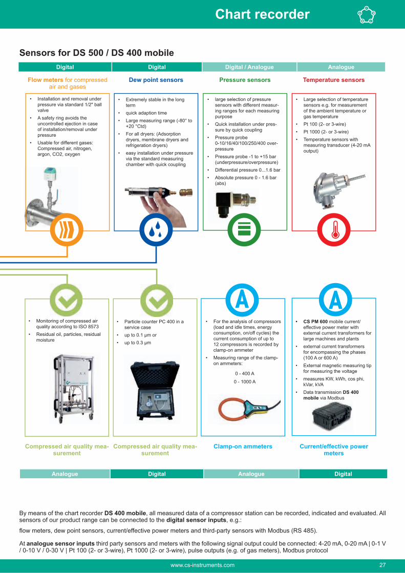
• CS PM 600 mobile current/effective power meter with external current transformers for large machines and plants
• external current transformers for encompassing the phases (100 A or 600 A)
• External magnetic measuring tip for measuring the voltage
• measures KW, kWh, cos phi, kVar, kVA
• Data transmission DS 400 mobile via Modbus
• Installation and removal under pressure via standard 1/2" ball valve
• A safety ring avoids the uncontrolled ejection in case of installation/removal under pressure
• Usable for different gases: Compressed air, nitrogen, argon, CO2, oxygen
• Extremely stable in the long term
• quick adaption time• Large measuring range (-80° to
+20 °Ctd)• For all dryers: (Adsorption
dryers, membrane dryers and refrigeration dryers)
• easy installation under pressure via the standard measuring chamber with quick coupling
• large selection of pressure sensors with different measur-ing ranges for each measuring purpose
• Quick installation under pres-sure by quick coupling
• Pressure probe 0-10/16/40/100/250/400 over-pressure
• Pressure probe -1 to +15 bar (underpressure/overpressure)
• Differential pressure 0...1.6 bar• Absolute pressure 0 - 1.6 bar
(abs)
• Large selection of temperature sensors e.g. for measurement of the ambient temperature or gas temperature
• Pt 100 (2- or 3-wire)• Pt 1000 (2- or 3-wire)• Temperature sensors with
measuring transducer (4-20 mA output)
• For the analysis of compressors (load and idle times, energy consumption, on/off cycles) the current consumption of up to 12 compressors is recorded by clamp-on ammeter
• Measuring range of the clamp-on ammeters:
0 - 400 A
0 - 1000 A
Flow meters for compressed air and gases
Dew point sensors Pressure sensors Temperature sensors
Compressed air quality mea-surement
Clamp-on ammeters Current/effective power meters
• Monitoring of compressed air quality according to ISO 8573
• Residual oil, particles, residual moisture
Digital Digital Digital / Analogue Analogue
Analogue Digital Analogue Digital
By means of the chart recorder DS 400 mobile, all measured data of a compressor station can be recorded, indicated and evaluated. All sensors of our product range can be connected to the digital sensor inputs, e.g.:
flow meters, dew point sensors, current/effective power meters and third-party sensors with Modbus (RS 485).
At analogue sensor inputs third party sensors and meters with the following signal output could be connected: 4-20 mA, 0-20 mA | 0-1 V / 0-10 V / 0-30 V | Pt 100 (2- or 3-wire), Pt 1000 (2- or 3-wire), pulse outputs (e.g. of gas meters), Modbus protocol
• Particle counter PC 400 in a service case
• up to 0.1 m or• up to 0.3 m
Compressed air quality mea-surement
Sensors for DS 500 / DS 400 mobile
www.cs-instruments.com 27
Chart recorder

In the menu of the DS 500 mobile / DS 400 mobile, the flow meter VA 500 can be set to the respective pipe inside diameter. Furthermore, the unit, the gas type and the reference condition can be set. The meter reading can be set to “zero” if necessary.
Graphic viewIn the graphic view all measured values are indicated as curves.It is possible to browse back on the time axis by a slide of the finger (without data logger maximum 24 h, with data logger back to the start of the measurement).
Data loggerWith the option “integrated data logger”, the measured values are stored in the DS 500/DS 400. The time interval can be freely set. Furthermore there is the possibility to fix the starting time and the end time of the data recording. Read-out of the measured data via USB interface or via the optional Ethernet interface.
Selection of the languageMany languages are already stored in every DS 500 mobile/DS 400 mobile. The desired language can be selected via the selection button.
All relevant parameters at a glanceIn addition to the flow rate in m³/h, the DS 500 mobile/DS 400 mobile also displays other parameters such as total consump-tion in m³ and speed in m/s.
www.cs-instruments.com28
Chart recorder

DESCRIPTION ORDER NO.
DS 400 mobile - chart record-er with graphic display, touch screen and integrated data logger
Sensor input1 and 2
Sensor input3 and 4
Digital (Z500 4003) -------- 0500 4012 D
Digital (Z500 4003) Digital (Z500 4003) 0500 4012 DD
Digital (Z500 4003) Analogue (Z500 4001) 0500 4012 DA
Analogue (Z500 4001) -------- 0500 4012 A
Analogue (Z500 4001) Analogue (Z500 4001) 0500 4012 AA
Options:Option: Integrated Ethernet and RS 485 interface Z500 4004
Option: Integrated webserver Z500 4005
Option: “Mathematics calculation function” for 4 freely selectable channels, (virtual channels): addition, subtraction, division, multiplication
Z500 4007
Option: “Totaliser function for analogue signals” Z500 4006
Further accessories:CS Basic – data evaluation graphically and in tabular form - reading of the measured data via USB or Ethernet, license for 2 workstations
0554 8040
CS Soft Energy Analyzer for energy and leakage analysis of compressed air stations
0554 7050
Connection cable for pressure, temperature and third-party sensors to mobile devices, ODU/open ends, 5 m
0553 0501
Connection cable for pressure, temperature and third-party sensors to mobile devices, ODU/open ends, 10 m
0553 0502
Connection cable for VA / FA sensors to mobile devices, ODU/M12, 5 m 0553 1503
Extension cable for mobile devices ODU/ODU, 10 m 0553 0504
length 5 m0553 0506
Case for all sensors (dimensions: 500 x 360 x 120 x mm) 0554 6006
INPUT SIGNALSCurrent signalsinternal or external power supplyMeasuring rangeResolutionAccuracyInput resistance
(0…20 mA/4…20 mA)
0…20 mA0.0001 mA± 0.03 mA ± 0.05 %
Voltage signal:Measuring rangeResolutionAccuracyInput resistance
(0…1 V)0…1 V0.05 mV± 0.2 mV ± 0.05 %
Voltage signalMeasuring rangeResolutionAccuracyInput resistance
(0...10 V / 30 V)0…10 V0.5 mV± 2 mV ± 0.05 %
RTD Pt 100Measuring rangeResolutionAccuracy
-200…850 °C0.1 °C± 0.2 °C (-100…400 °C)± 0.3 °C (further range)
RTD Pt 1000Measuring rangeResolutionAccuracy
-200…850 °C0.1 °C± 0.2° (-100…400 °C)
PulseMeasuring range
Min pulse length 500 μs frequency 0...1 kHzmax. 30 VDC
TECHNICAL DATA DS 400 MOBILEDimensions: 270 x 225 x 156 mm (W x H x D)
Weight: 2.2 kg
Inputs: 2 x 2 sensor inputs for digital or analogueue sensor signals
Interface: USB (standard), Ethernet (optional)
Power supply: Internal rechargeable Li-Ion batteries, approx 8 h continuos opera-tion, 4 h charging time
Options:Integrated data logger: 100 million measured values start/stop time, measuring rate freely
adjustable
2 additional sensor inputs: For connection of pressure sensors, temperature sensors, clamp-on ammeters, third-party sensors with 4...20 mA, 0 to 10 V, Pt 100, Pt 1000
Technical data of DS 400 mobile
Digital Digital Digital Digital
m³/h, m³ °Ctd A, kW/h
Flow sensor
Dew point sensors
Current/
power meter
Third-par-ty sen-
sors with RS 485
MOD-BUS
DigitalAnalogue Analogue Analogue
Analogue
bar A °C °C
Pressure sensor
Clamp-on ammeter
Tem-perature sensor
Third par-ty sensor analogue
output
4…20 mA 0…20 mA0…10 VPulsePt 100
Pt 1000
Matching sensors can be found on pages 32 to 35
www.cs-instruments.com 29
Chart recorder

PI 500 - Hand-held measuring device for the industry
Measurement curves are displayed graphically, so the operator sees at a glance the behaviour of the dryer from the start of the measurement.
All physical parameters of the humid-ity measurement are calculated auto-matically. The PI 500 also displays the measured values of the external sensor.
Up to 100 million measured values can be stored. Each measurement can be stored with a comment, e.g. measuring site name. The time inter-val can be freely set.
The new PI 500 is an all-purpose hand-held measuring device for many applications in the industry, like e. g.:
• Flow measurement• Pressure/vacuum measurement• Temperature measurement• Moisture/dew point measurementThe graphic indication of colored measurement curves is inimitably.Up to 100 million measured values can be stored with date and name of measuring site. The measured values can be transferred to the computer by means of a USB stick. The data can be conveniently evaluated with the CS Basic software.
Measured data and service reports can be issued easily and quickly. The following probes can optionally be connected to the freely configurable sensor input of PI 500:
• Pressure sensors (high and low pressure)
• Flow probes, VA 500/VA 520
• Temperature sensors Pt 100, Pt 1000/4…20 mA
• Dew point sensors FA 510
•
• Optional third-party sensors with the following signals: 0...1/10 V, 0/4...20 mA, Pt 100, Pt 1000, pulse, Modbus
Special features:
• Universal sensor input for many common sensor signals
• Internal rechargeable Li-Ion batteries (approx. 12 h continuous operation)
• 3.5" graphic display / easy operation via touch screen
• Integrated data logger for storage of the measured values
• USB interface for reading out via USB stick
• International: International: Up to 8 languages selectable
www.cs-instruments.com30
Chart recorder

DESCRIPTION ORDER NO.PI 500 portable measuring instrument with integrated data logger 0560 0511
Option: “Mathematics calculation function” for 4 freely selectable channels, (virtual channels): addition, subtraction, division, multiplication
Z500 5107
Option: „Totaliser function for analogue signals“ Z500 5106
CS Basic – data evaluation graphically and in tabular form - reading of the measured data via USB or Ethernet, license for 2 workstations
0554 8040
Transport case 0554 6510
TECHNICAL DATA PI 500Display: 3.5" touch panel TFT transmissive, graphics, curves, statistics
Interfaces: USB interface
Power supply for sensors::
Output voltage: 24 VDC ± 10%Output current: 120 mA in continuous operation
Power supply: Internal rechargeable Li-Ion batteries, charging time approx. 4 h, PI 500 continuous operation> 4h depending on power consumption for ext. sensor
Power adapter: 100 - 240 VAC / 50 - 60 Hz, 12 VDC - 1A, safety class 2 only for use in dry rooms
Dimensions: 82 x 96 x 245 mm
Housing material: PC/ABS
Weight: 450 g
Operating tempera-ture:
0…50 °C ambient temperature
Storage temperature: -20 to +70°C
EMC: DIN EN 61326
Sensor input: For connection of pressure and temperature sensors, clamp-on ammeters, third-party sensors with 4 ... 20 mA, 0-10 V, Pt 100, Pt 1000, Modbus
Memory Size: 8 GB memory card standard
INPUT SIGNALSCurrent signalsinternal or external power supplyMeasuring rangeResolutionAccuracyInput resistance
(0…20 mA/4…20 mA)
0…20 mA0.0001 mA± 0.03 mA ± 0.05 %
Voltage signal:Measuring rangeResolutionAccuracyInput resistance
(0…1 V)0…1 V0.05 mV± 0.2 mV ± 0.05 %
Voltage signalMeasuring rangeResolutionAccuracyInput resistance
(0...10 V / 30 V)0…10 V0.5 mV± 2 mV ± 0.05 %
RTD Pt 100Measuring rangeResolutionAccuracy
-200…850 °C0.1 °C± 0.2 °C (-100…400 °C)± 0.3 °C (further range)
RTD Pt 1000Measuring rangeResolutionAccuracy
-200…850 °C0.1 °C± 0.2° (-100…400 °C)
PulseMeasuring range
Min pulse length 500 μs frequency 0...1 kHzmax. 30 VDC
Flow meterVA 520
Pressure sensor
Clamp-on ammeter
Screw-in temperature probe
Pt 1000 Current/effective power meters
Flow sensorVA 500
Third-party sensors0-1/10 V
(0) 4...20 mAPulse
Modbus/RS 485
Flow meterVA 520
Dew point sensorFA 510
PI 500 - Hand-held measuring instrument with large sensor selection
Further sensors can be found on pages 32 to 35
www.cs-instruments.com 31
Chart recorder

Suitable sensors for DS 500 mobile, DS 400 mobile, PI 500, DP 510, LD 510
FLOW METERS INSERTION-VERSION ORDER NO.
connection cable to mobile devices0695 1124
5 m connection cable to mobile devices0695 1125
VA 550 Flow meter, measuring head in robust aluminium die casting housing 0695 0550+ order code A_…M…_
FLOW METERS INLINE VERSION ORDER NO.Flow meter VA 520 with integrated measuring section, (R 1/4" DN 8) 0695 0520
Flow meter VA 520 with integrated measuring section, (R 1/2" DN 15) 0695 0521
Flow meter VA 520 with integrated measuring section, (R 3/4" DN 20) 0695 0522
Flow meter VA 520 with integrated measuring section, (R 1" DN 25) 0695 0523
Flow meter VA 520 with integrated measuring section, (R 1 1/4" DN 32) 0695 0526
Flow meter VA 520 with integrated measuring section, (R 1 1/2" DN 40) 0695 0524
Flow meter VA 520 with integrated measuring section, (R 2" DN 50) 0695 0525
0695 0570+ order code A_...K_0695 0571
0695 0572
0695 0573
0695 0574
0695 0575
Inline flow meter
DEW POINT SENSORS ORDER NO.FA 510 dew point sensor, -80...+20 °Ctd incl. measuring chamber mobile and 5 m connection cable to mobile devices
0699 1510
FA 510 dew point sensor, -20...+50 °Ctd incl. measuring chamber mobile and 5 m connection cable to mobile devices
0699 1512
CONNECTION CABLE FOR VA 500/520 AND FA 510 SENSORS ORDER NO.Connection cable for VA / FA sensors to mobile devices, ODU/M12, 5 m 0553 1503Extension cable for mobile instruments, ODU / ODU, 10 m 0553 0504
CALIBRATION CERTIFICATES FOR FLOW METERS AND DEW POINT SENSORS
ORDER NO.
3200 0001
0699 3396
VA 500 VA 550
VA 520
VA 570
FA 510
ODU/M12
Extension cable
www.cs-instruments.com32
Chart recorder

PRESSURE SENSORS ± 1% ACCU-RACY
± 0,5% ACCU-RACY
Standard pressure probe CS 16, 0...16 bar 0694 1886 0694 3555
Standard pressure probe CS 40, 0…40 bar 0694 0356 0694 3930
Standard pressure probe CS 1.6, 0...1.6 bar abs. 0694 3550
Standard pressure probe CS 10, 0…10 bar 0694 3556 0694 3554
Standard pressure probe CS 100, 0…100 bar 0694 3557
Standard pressure probe CS 250, 0…250 bar 0694 3558
Standard pressure probe CS 400, 0…400 bar 0694 3559
Precision pressure probe CS -1...+15 bar, ± 0.5 % accuracy of. f.s.
0694 3553
0694 3561
whole measuring range3200 0004
TEMPERATURE SENSORS ORDER NO.Bendable temperature sensor PT 100 (2-wire) class B, length: 300 mm, d=3 mm, -70…+500 °C, connection cable 2 m PFA with ODU plug (8-pin) to mobile devices
0604 0200
Screw-in temperature sensor PT 100 class A, length 300 mm, d = 6 mm, with measuring transducer 4...20 mA = -50 °C...+ 500 °C (2-wire)
0604 0201
Cross-band surface probe, thermocouple type K with measuring transducer4…20 mA = 0°C…+180 °C, 2 m cable PVC with ODU plug (8-pole) to mobile devices
0604 0202
Cable temperature sensor PT 100 class A (4-wire), length: 300 mm, d = 6 mm, -70 ... +260 ° C, 5 m connection cable PFA with open ends
0604 0205
Cable temperature sensor PT 100 class A (4-wire), length: 100 mm, d = 6 mm, -70...+260 °C, 5 m connection cable PFA with open ends
0604 0206
Cable temperature sensor PT 100 class A (4-wire), length: 200 mm, d = 6 mm, -70...+260 °C, 5 m connection cable PFA with open ends
0604 0207
Magnetic surface temperature sensor, holding magnet 39x26x25 mm, PT 100 class B (2-wire), -30...+180 °C, 5 m connection cable PFA with open ends
0604 0208
10 barMaterial: stainless steel, application area: max. + 260 °C
0554 0200
Pressure-tight up to 16 bar, material: stainless steel, application area: max. + 260 °C
0554 0201
0520 0180
CONNECTION CABLES FOR PRESSURE SENSORS / TEMPERATURE SENSORS
ORDER NO.
Connection cable for pressure, temperature or third-party sensors on mobile devices, ODU/open ends, 5 m
0553 0501
Connection cable for pressure, temperature or third-party sensors on mobile devices, ODU/open ends, 10 m
0553 0502
Extension cable for mobile instruments, ODU / ODU, 10 m 0553 0504
ODU plug for connection to mobile devices Z604 0104
Suitable sensors for DS 500 mobile, DS 400 mobile, PI 500, DP 510, LD 510
0604 0201
0604 0205
0554 0200
ODU connector
Connection cable/ODU
0604 0208
DIGITAL PRESSURE SENSORS ± 1% ACCU-RACY
± 0,5% ACCU-RACY
Digital pressure probe DPS 16, 0…16 bar RS 485, G1/2"
0694 2886 0694 4555
Extension cable
www.cs-instruments.com 33
Chart recorder

CURRENT/EFFECTIVE POWER METER ORDER NO.0554 5341
0554 5342
-and systems
- External current transformers for encompassing the phases (100 A or 600 A) -Var, kVA
- Data transfer to DS 500 mobile / DS 400 mobile via Modbus -
Current transformer 100A/1A consisting of 3 transformers for mobile instruments
Z554 0001
Current transformer 600A/1A consisting of 3 transformers for mobile instruments
Z554 0002
Current transformer 1000A/1A consisting of 3 transformers for mobile instruments
Z554 0003
ANY THIRD-PARTY SENSOR CONNECTABLEAdditionally, any third-party sensors with the following signal outputs can be connected:
• 4-20 mA
• 0-20 mA
• 0-1 V/0-10 V/0-30 V
• Pt 100 (2- or 3-wire)
• Pt 1000 (2- or 3-wire)
• Pulse outputs (e. g. of gas meters)
• Frequency output
• Modbus protocol
Suitable sensors for DS 500 mobil, DS 400 mobil, PI 500
Third-party sensors0 - 1/10 V
Third-party sensorsRS 485 Modbus RTU
Third-party sensorsPulse
Third-party sensors0/4…20 mA
CLAMP-ON AMMETERS ORDER NO.Clamp-on ammeter 0...1000 A TRMS incl. 3 m connection cable 0554 0519
Clamp-on ammeter 0...400 A TRMS incl. 3 m connection cable 0554 0511
Clamp-on ammeter
Suitable sensors for DS 500 mobile, DS 400 mobile, PI 500, DP 510, LD 510
www.cs-instruments.com34
Chart recorder

CS PM 600 - for: DS 500 mobile / DS 400 mobile / PI 500
DESCRIPTION ORDER NO.0554 5341
0554 5342
• big machines and systems
• External current transformers for encompassing the phases (100 A or 600 A)• External magnetic measuring tip for measuring the voltage• Measures kW, kWh, cos, phi, kVar, kVA• Data transfer via Modbus•
instruments, 5 m
Current transformer 100A/1A consisting of 3 transformers for mobile instruments Z554 0001
Current transformer 600A/1A consisting of 3 transformers for mobile instruments Z554 0002
Current transformer 1000A/1A consisting of 3 transformers for mobile instruments Z554 0003
TECHNICAL DATA CS PM 600
Parameters: Voltage (Volt)Current (Ampere)Cos phi
Apparent power (kVA)Reactive power (kVar)Active energy (kWh)Power frequency (Hz)All parameters are trans-ferred digitally to DS 500 mobile /DS 400 mobile
Accuracycurrent mea-surement:
Threshold values for current deviation. Loss angle ac-cording to IEC 60044-1.Current deviation in % at rated current in120% 1100% 120% 1.55% 3
Accuracy active energy:
IEC 62053-21 Class 1
Sensor connec-tions:
3 x current transformers(L1,L2,L3,N)4 x voltage measurement(L1,L2,L3,N)
Interfaces: RS 485 (Modbus protocol)
Measuring range:
Voltage measurement max. 400 VoltCurrent measurement max. 100 A or 600 A
Size current transformers:
100 A / 1 A(max. 24 mm wire),600 A / 1 A(max. 36 mm wire)
Dimensions case:
270 x 225 x 156 mm(B x H x T)
Operating tem-perature:
- 10…+40 °C
Measures voltage, current and calculates:
Effective power [kW]Apparent power [kVA]Reactive power [kVar]Active energy [kWh]cos phi
All measured data are transferred digitally (Modbus) to DS 500 mobile/ DS 400 mobile and can be recorded there.
Example: Measurement on the compressor
Special features:
• Magnetic voltage measuring tips for pick-
• Hinged current transformers encompass the conductors of the phases L1, L2, L3. This can also be done during operation
Magnetic voltage measuring tips elec-trically isolated
Current transformer can be opened
www.cs-instruments.com 35
Chart recorder

Energy analysis - consumption measurement - leakage calculationDS 500 mobile - Energy analysis according to DIN EN 50001
If we talk about operating costs in compressed air systems, we are actually talking about the energy costs, because the electricity costs make up about 70-80% of the total cost of a compressed air system. Depending on the size of the system, this means considerable operating costs.
Even in smaller systems, this may quickly add up to €10,000 to 20,000 per year. This is an amount which can be consider-ably reduced – even in case of well operated and maintained plants. This will also apply to your compressed air system without a doubt!
Which are your actual costs per generated m³ air? Which en-ergy is gained due to the waste heat recovery? What is the total performance balance of your plant?
www.cs-instruments.com36
Chart recorder

Hole diameter Air loss at Energy loss at Cost atmm 12 bar 6 bar 12 bar
1 1.2 1.8 0.3 1.0 144.00 480.003 11.1 20.8 3.1 12.7 1488.00 6096.005 30.9 58.5 8.3 33.7 3984.00 16176.0010 123.8 235.2 33.0 132.0 15840.00 63360.00
What is the differential pressure of individ-ual filters? What is the humidity (pressure dew point)? How much compressed air is consumed?
Although compressed air is one of the most expensive forms of energy, there are often enormous energy losses in factories, especially in this area.
They are mainly caused by the following factors:
• Disuse of the waste heat
• Leakages of up to 50%
• Missing compressor control system
• Compressed air losses
Lots of systems are not adapted to the actual demand or they are in need of repair. Leak curing programs could save about 1.7 million tons of carbon dioxide emissions per year. (Source: Fraunhofer Institut, Karlsruhe).
So there is a considerable amount of pos-sible energy savings slumbering in the compressed air lines of lots of enterprises. To tap into this, the heat generated during compressed air generation should be used to heat the space or to heat water.
Furthermore, it is important to optimise the control of compressed air stations because this will lead to considerable energy sav-ings in any case. Also the restoration of an ailing or no longer suitable compressed air supply will pay off after only a short period of time. Losses due to leakages within the pipe network incur high costs.
This table shows the annual energy costs incurred by leaks:
(Source: compressed air efficiency, kW x
Energy resources like electricity, water and gas are usually monitored and therefore the costs are transparent.
Water consumption, for example, is pre-cisely measured with consumption meters. Contrary to compressed air, a water leak is visible for all to see straight away and therefore fixed immediately. Leakages in the compressed air network „blow out“ unnoticed, even on weekends and during production stops.
The compressors continue to run during this time just to maintain a constant pres-sure in the network. For mature com-pressed air networks, the leak rate can be between 25 and 35 percent. They are the most industrious consumers working 365 days a year.
Not considered in these considerations are the costs of “producing clean and dry” com-pressed air. Refrigeration and adsorption dryers dry the air with significant operating costs, which then “blows out” uselessly.
With ever-increasing energy costs, these potential savings must be used more and more to stay competitive within the market. Savings potential can only be exploited if the consumption of individual machines or systems is known and made transparent for all.
When introducing an energy management system according to DIN EN 16001, all consumers have to recorded in the first step. This gives the user an overview of what is being consumed. This transpar-ency makes it possible to deliberately intervene and save energy. In compressed air systems this means, in the first step, to detect and eliminate leaks.
Especially for the complete monitoring and consumption analysis of compressor sta-tions and compressed air lines we devel-oped a portable measuring system, the DS 500 mobile. DS 500 mobile meets with all requirements for analyzing a compressed air system.
In addition to the evaluation of standard sensors such as for example:
• Flow meters,• Pressure dew point,• Pressure,• Differential pressure,• Absolute pressure,• Temperature sensors
, the connection of all kinds of third-party sensors such as:
• Pt 100• Pt 1000• 0/4…20 mA• 0-1/10 V• pulse• RS 485 Modbus etc.
is also possible. One of the main advan-tages of DS 500 mobile is the possibility to connect not only clamp-on ammeters but also external power meters, water meters or heat meters. As such, the current costs can be included very accurately in the anal-ysis and typical figures of a compressed air plant can be determined.
www.cs-instruments.com 37
Chart recorder

DS 500 mobile enables an intelligent energy analysis in a quick and easy way. The data will be indicated immediately in the display.
For this purpose just the costs in € per kWh (please consider day and night tariff) have to be entered.
By means of a mathematical function typ-ical calculations can be carried out like for example:
• Costs in € per generated m³ of com-pressed air
• Specific output in kWh/m³
• Consumption of single compressed air lines including summation
• Indication of Min-Max values, aver-age value
If the minimum values rise continuously over the years this is a clear signal that the leakage rate increases. This can easily be determined by carrying out the measure-ments in regular intervals.
Consumption analysis including statis-tics at the touch of a button
Besides the compressed air also all other energy costs like current, water, vapor etc. can be recorded in this evaluation. This creates transparency.
So all energy and flow meters for com-pressed air, gas, water, vapor and so on can be recorded and evaluated. The cus-tomer gets the costs in €uro.
On the big 7" colour display with touch panel, all information is visible at a glance. By means of the evaluation software CS Soft Basic all data can be evaluated online at the PC via a USB stick or Ethernet.
Additionally to the consumption analysis as daily/weekly or monthly report an alarm can be sent by e-mail or SMS in case of threshold value exceedance.
The measured data can be retrieved all over the world via the webserver, GSM module.How is this done in practice?
Step 1: MeasurementIt is a special advantage that up to 12 com-pressors can be measured with one DS 500 mobile at the same time.
Step 2: Analysis
The energy consumption of every single compressor is measured by means of a clamp-on ammeter. The produced com-pressed air quantity is calculated by the software on a basis of the performance data of the compressor which have to be entered.
• The following parameters are cal-culated additionally:
• • Load,• Idle,• Stop time,• Compressor load in %,• Number of load/unload cycles, spe-
cific output in kWh/m³,• Costs in €/m³
-ment and real consumption measure-
The system analysis has the same func-tion like the compressor analysis, how-ever, it additionally offers the possibility to measure the actually produced resp. used quantity of compressed air by means of the flow sensor VA 500.
With the additional „real consumption mea-surement“ the leakages and therefore the cost share of the leakages in comparison to the total costs in € can be determined.
The leakage calculation is carried out during production-free time (shutdown, weekend, holidays). The flow meter VA 500 measures the actual supplied quantity. The compressor delivers compressed air during this down time, in order to maintain a constant pressure.
According to statistics, even if production is carried out day and night, there is at least one short period of time during which all load is switched off. By means of this data, the software defines a calculated leakage rate and calculates the incurred leakage costs in €.
Step 3: Evaluation at the PC with graphics and statistics
Specific data have to be entered before the analysis is carried out:
• Selection of compressor type (load/idle resp. variable speed drive con-
• As well as entry of the perfor-mance data according to data sheet
• Period of measurement
• Costs in € for 1 kWh
www.cs-instruments.com38
Chart recorder

and week view
Everything at a glance:
The user gets a day and week view of all stored measured data with his company logo (can be easily integrated) at the touch of a button. By means of the zoom and the cross lines function peak values can be determined.
At the touch of a button the user gets all important data like e. g.:
• Electricity costs• Compressed air costs• Leakage costs in €• Compressor data with load/ idle
times• Specific output in kWh/m³
• Costs per m³ in €
Based on these analysis some measures should be carried out in order to optimize the compressed air system. These mea-sures may differ from system to system, however, normally there are the following possibilities:
• Please check whether there are leakages in the compressed air system and localize them. Usu-ally they occur at weld seams and junctions. (50 holes with a diameter smaller than 1 mm may cause incur
• By means of the load/idle analysis and the pressure profile the com-pressor regulation and adjustment should be optimized. Modern com-pressor operation systems help to minimize the idle times. (During idle times, the compressor takes up about 30 % of the full load energy, however, it does not release any
• Reduce the input temperature (a temperature reduction by about
• Optimize the pipe system by avoid-ing unnecessary pressure drops.
www.cs-instruments.com 39
Chart recorder

40
DP 500/510 - Mobile dew point meters with data logger
Special features:
• Precise dew point measurement down to -80 °Ctd
• Quick response time
• 3.5" graphic display / easy operation via touch screen
• Integrated data logger for storage of the measured values
• USB interface for reading out via USB stick
• Calculates all necessary moisture parameters like g/m³, mg/m³, ppm V/V, g/kg, °Ctdatm
• 2nd freely assignable sensor input for third-party sensors (only DP 510)
• International: up to 8 languages selectable
Quick installation by means of mea-suring chamber and quick coupling
Ideal for service technicians - every-thing in one case
Dry container - for sensor protec-tion and quick adaption time
Third-party sensors 0-1/10 V
(0) 4...20 mA PulseModbus/RS 485
Flow probeVA 500
Flow meterVA 520
Pressure sensor
Clamp-on ammeter
Screw-in temperature probePt 100
Cable temperature sensor Pt 100
Current/effective power meters
Transfer of data to the PC via USB stick
Applications:
• Compressed air: Examination of refrigeration, mem-brane, adsorption dryers
• Technical gases: Residual moisture measurement in gases such as N2, O2 etc.
• Plastics industry: Examination of granulate dryers
2nd freely assignable sensor input for third-party sensors (only DP 510)
The whole range of suitable sensors can be found on pages 32 to 34
Dew point sensor FA 510
www.cs-instruments.com40
Dew point

Everything at a glance
measurement curves are displayed graph-ically, so the operator sees at a glance the behavior of the dryer since the start of the measurement.
All physical parameters of the humidity measurement are calculated automatically. The DP 510 also displays the measured values of the external sensor.
Up to 100 million measured values can be stored. Each measurement can be stored with a comment, e.g. measuring site name. The time interval can be freely set.
DESCRIPTION ORDER NO.Set DP 500 in a case - consisting of: 0600 0500 - Portable dew point meter DP 500 for compressed air and gases 0560 0500
- Mobile measuring chamber up to 16 bar 0699 4490
- 0554 0003
- Power supply for DP 500/DP 510 0554 0009
- Control and calibration set 11.3% RH 0554 0002
- Quick-lock coupling 0530 1101
- Dry container for CS dew point sensors 0699 2500
- Transportation case (small) for DP 500 0554 6500
Set DP 510 in a case - consisting of: 0600 0510 - Mobile dew point meter DP 510 with one additional input for external sensors
0560 0510
- Mobile measuring chamber up to 16 bar 0699 4490
- 0554 0003
- Power supply for DP 500/DP 510 0554 0009
- Control and calibration set 11.3% RH 0554 0002
- Quick-lock coupling 0530 1101
- Dry container for CS dew point sensors 0699 2500
- Transportation case (large) for DP 510 as well as other sensors 0554 6510
Furter options, not included in the set:Option: „Mathematics calculation function“ for 4 freely selectable chan-nels, (virtual channels): addition,subtraction, division, multiplication
Z500 5107
Option: „Totaliser function for analogue signals“ Z500 5106
CS Basic – data evaluation graphically and in table form - reading of the measured data via USB or Ethernet, licence for 2 workstations
0554 8040
0699 3396
Additional calibration point freely selectable in the range between -80...+20 °Ctd
0700 7710
High pressure measuring chamber up to 350 bar 0699 3590
Measuring chamber for atmospheric dew point 0699 3690
Measuring chamber for granulate dryers with minimum overpressure 0699 3490
Portable dew point meter DP 510 for compressed air and gases(high pressure version up to 350 bar)
0560 0512
Portable dew point meter DP 500 for compressed air and gases(high pressure version up to 350 bar)
0560 0501
TECHNICAL DATA DP 500/510
Display: 3.5" touch screen
Measuring range: -80…+50 °Ctd-20…+70 °C0…100% RH
Accuracy: ± 0.5 °Ctd at-10…+50 °CtdTyp. ± 2 °Ctd (further range)
Moisture parame-ters:
g/m³, mg/m³, ppm V/V, g/kg, °Ctdatm, % RH
Pressure range: -1…50 bar standard-1…350 bar special version
Interface: USB interface
Data logger: 8 GB SD memory card (100 million values)
Power supply: Output voltage: 24 VDC ± 10%Output current: 120 mA in continuous operation
Power supply: Internal rechargeable Li-Ion batteries, approx. 12 h continuous operation, 4 h charging time
Screw-in thread: G 1/2" stainless steel
Ambient tempera-ture:
0…+50 °C
EMC: DIN EN 61326-1
Photo key saves current screen as an image file. No additional software neces-sary.
Photo key
41www.cs-instruments.com 41
Dew point

42
DP 400 mobile with integrated dew point and pressure measurementFor measurement of all humidity parameters under pressure up to 16 bar
The DP 400 mobile with integrated, rechargeable battery has been developed especially for field use. In addition to a highly precise dew point sensor, a precise pressure sensor is also installed in the device up to 16 bar. So in addition to the pressure dew point in °Ctd, the temperature in °C and the line pressure in bar, further moisture parameters (% RH, mg/m³, g/m³) as well as pressure-dependent measured values (g/kg, ppm v/v, atm. dew point °C) can also be calculated.
SPECIAL FEATURES:
• Precise dew point measurement down to -80 °Ctd, ppm V/V, atmospheric dew point
•
• Integrated pressure measurement up to 16 bar
• Integrated measuring chamber with integrated dry container protects the dew point sensor during transport and guarantees quick adaption time
• Humidity sensor with long-term stability: precise, condensation-resistant, quick adaption time
• Optional: 2 further sensor inputs for external sensors
• Optional: Integrated data logger
6 mm plug connection for measuring gas/com-pressed air feed
Option:Two further sensor inputs for: (flow, pressure, dew point, 4...20 mA, Mod-bus-RTU…)
www.cs-instruments.com42
Dew point
Easy operation via touchscreen
TECHNICAL DATA DP 400 MOBILDisplay: 3.5" touch screen
Measuring range: -80…+50 °Ctd-20…+70 °C0…100% RH0…16 bar ± 0.5 %
Accuracy: ± 1 °C at 50…-20 °Ctd± 2 °C at -20…-50 °Ctd± 3 °C at -50…-80 °Ctd
Moisture parameters: g/m³, mg/m³, ppm V/V, g/kg, °Ctdatm, % RH
Interface: USB interface
Data logger option: 8 GB SD memory card (100 million values)
Power supply for exter-nal sensors:
Output voltage: 24 VDC ± 10%Output current: 120 mA in continuous operation
Power supply: Internal rechargeable Li-Ion batteries, approx. 12 h continuous operation, 4 h charging time
Process connection: 6 mm plug connections
Ambient temperature: 0…+50 °C
EMC: DIN EN 61326-1
DESCRIPTION ORDER NO.
DP 400 mobile - Portable dew point meter with integrated pressure measurement, incl. transportation bag for PTFE hose and power supply
0500 4505
Option: Integrated data logger for 100 million measured values Z500 4002
Option: Integrated Ethernet and RS 485 interface Z500 4004
Option: Integrated webserver Z500 4005
Option: “Mathematics calculation function” for 4 freely selectable chan-nels, (virtual channels): addition, subtraction, division, multiplication
Z500 4007
Option: 2 additional sensor inputs for external sensors (1 x digital sen-sor Modbus, 1 x analogueue sensor)
Z500 4001
CS Basic – data evaluation graphically and in tabular form - reading of the measured data via USB or Ethernet, license for 2 workstations
0554 8040
Connection cable for VA / FA sensors to mobile devices, ODU/M12, 5 m 0553 1503
Connection cable for pressure, temperature or third-party sensors on mobile devices, ODU/open ends, 5 m
0553 0501
Connection cable for pressure, temperature or third-party sensors on mobile devices, ODU/open ends, 10 m
0553 0502
Extension cable for mobile instruments ODU/ODU, 10m 0553 0504
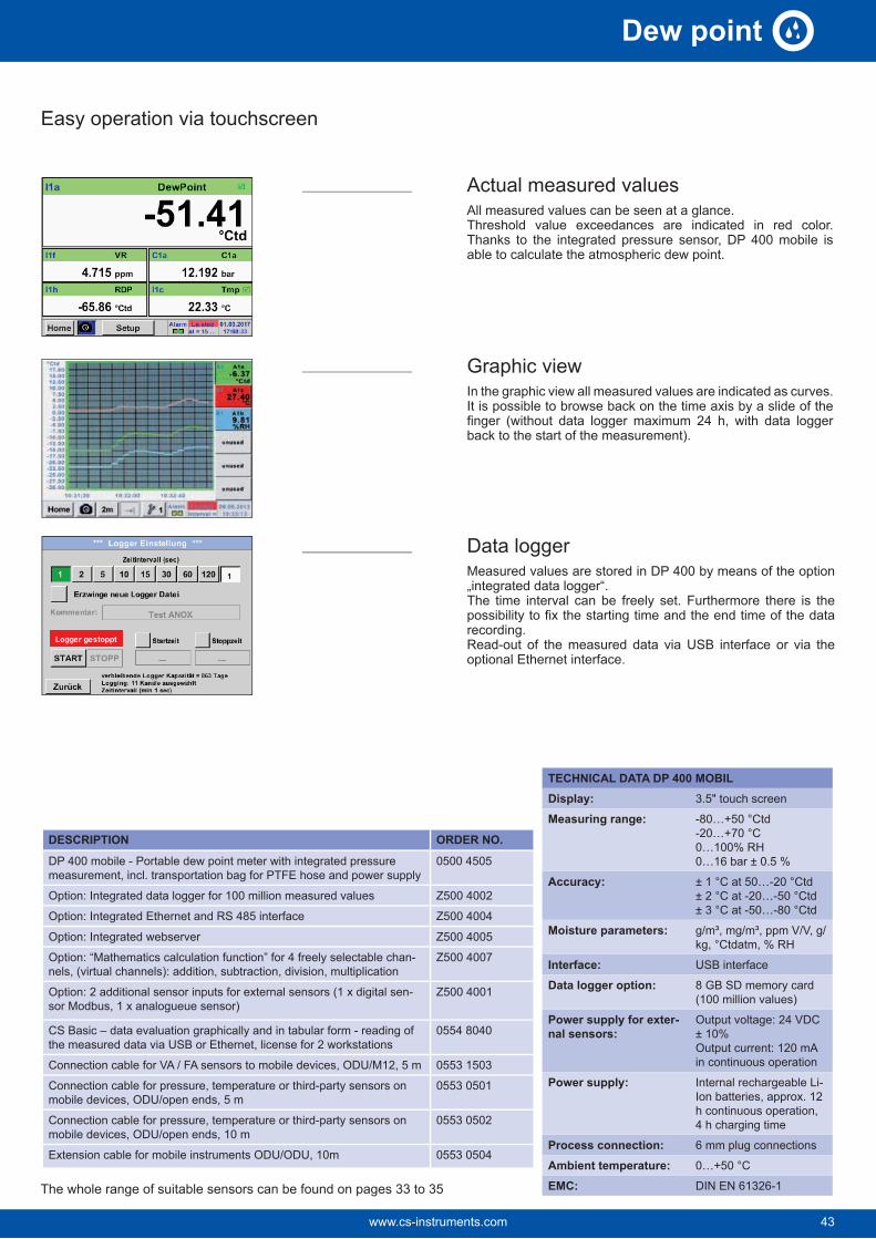
Actual measured valuesAll measured values can be seen at a glance.Threshold value exceedances are indicated in red color. Thanks to the integrated pressure sensor, DP 400 mobile is able to calculate the atmospheric dew point.
Graphic viewIn the graphic view all measured values are indicated as curves.It is possible to browse back on the time axis by a slide of the finger (without data logger maximum 24 h, with data logger back to the start of the measurement).
Data loggerMeasured values are stored in DP 400 by means of the option „integrated data logger“.The time interval can be freely set. Furthermore there is the possibility to fix the starting time and the end time of the data recording.Read-out of the measured data via USB interface or via the optional Ethernet interface.
The whole range of suitable sensors can be found on pages 33 to 35
43www.cs-instruments.com 43
Dew point

44
FA 510/515 - Dew point sensor
Special features:
• Extremely stable in the long term
• Analog output 4...20 mA for dew point
• Condensation-resistant
• Quick adaption time
• Pressure-tight up to 350 bar (special version)
• NEW: Modbus-RTU interface
• NEW: Higher resolution of sensor signal due to the improved evaluation electronics
• NEW: Sensor diagnosis on site with a por-table device or CS Service Software
• Readable via Modbus: - Pressure dew point [°Ctd.] - Temperature [°C] - rel. humidity [% RH] - abs. humidity [g/m³] - Degree of humidity [g/kg] - Moisture content V/V [ppmV/V] - Partial vapour pressure [hPa] - Atmospheric dew point [°Ctd.atm]
Typical applications:
• Dew point measurement in the compressed air after adsorption dryer, membrane dryer, refrigeration dryer
• Residual moisture/dew point measurement in gases such as oxygen, nitrogen, argon...
• Residual moisture/dew point measurement after granulate dryers in the plastics industry
Recommendation:
Mounting with standard measuring chamber for compressed air up to 16 bar
Advantage: Easy installation via quick coupling
FA 510/515 for residual moisture measurement in compressed air and gases
TECHNICAL DATA FA 510/515Measuring range: -80…20 °Ctd, -20…50 °Ctd
Accuracy: ± 1 °C at 50…-20 °Ctd± 2 °C at -20…-50 °Ctd± 3 °C at -50…-80 °Ctd
Pressure range: -1…50 barSpecial version up to 350 bar
Power supply: 24 VDC (10…36 VDC)
Protection class: IP 65
EMC: In acc. with DIN EN 61326-1
Operating tempera-ture:
-20…70 °C
Connection: M12, 5-pin
PC connection: Modbus-RTU interface (RS 485)
Analogue output: 4…20 mA = -80…20 °Ctd4…20 mA = -20…50 °CtdFA 510: 4…20 mA (3-wire)FA 515: 4…20 mA (2-wire)
Burden for analogue output:Screw-in thread:
Optional: UNF 5/8", NPT 1/2"
Dimensions: Ø 30 mm, length approx. 130 mm
Via service software:Choose units
Scaling
% RH, °Ctd, g/m³, mg/m³, ppm V/V4…20 mA change
DESCRIPTION ORDER NO.FA 510 dew point sensor for adsorption dryers -80...20 °Ctd incl.
and Modbus-RTU interface
0699 0510
FA 515 dew point sensor for adsorption dryers -80°...20 °Ctd incl.
or Modbus-RTU interface
0699 0515
FA 510 dew point sensor for refrigeration dryer -20...50 °Ctd incl.
and Modbus-RTU interface
0699 0512
FA 515 dew point sensor for refrigeration dryer -20...50 °Ctd incl.
or Modbus-RTU interface
0699 0517
Connection cables:Connection cable for VA/FA series, 5 m 0553 0104
Connection cable for VA/FA sensors, 10 m 0553 0105
Option for FA 510:Option: analogue output FA 510, special version 2…10 volts Z699 0510
Options for FA 510/515:Option: max. pressure FA5xx 350 bar Z699 0515
Option: max. pressure FA5xx 500 bar Z699 0516
Option: special scaling FA5xx 4…20 mA=__ … __ g/m³, ppm etc. Z699 0514
Option: connection thread FA5xx, 5/8" UNF Z699 0511
Option: surface condition FA 5xx, free of oil & grease Z699 0517
Further accessories:Standard measuring chamber up to 16 bar 0699 3390
High pressure measuring chamber up to 350 bar 0699 3590
Stainless steel bypass measuring chamber for dew point measure-ment in gases under pressure
0699 3290
CS Service Software for dew point sensors incl. PC connection set (Modbus to USB Interface).
0554 2007
Calibration and adjustment:0699 3396
Additional calibration point freely selectable 0700 7710
www.cs-instruments.com44
Dew point

DS 52 - Dew point monitoring
Special features:• Plug-in system: everything wired and ready
• No time-consuming studying of the instruction manual
• 2 alarm contacts (250 VAC, 3 A) pre- and main alarm freely adjustable
• 4...20 mA analogue output
• Option alarm unit: Buzzer and continuous red light
Consisting of:Digital process meter DS 52
Option:Alarm unit (Buzzer and con-tinuous red light)
The dew point set is wired ready to plug in at the factory. The alarm values can be set freely. The dew point sensor FA 510 is extremely long-term stable and can be quickly and easily installed and removed under pressure via the screw-on measuring chamber incl. Quick coupling.
Dew point sensor FA 510
TECHNICAL DATA DISPLAY DS 52Dimensions: 118 x 92 x 93 mm
Display: LED red, 7-segment, height: 13 mm, 5-digit, 2 LED for alarm relay
Keypad: 4 keys
Input: 4…20 mA
Power supply: 230 VAC, 50/60 Hz; option: 24 VDC or 110 VAC 50/60 Hz
Alarm outputs: 2 x relay output, changeover contact, 250 VAC, max. 3 A
Operating tem-perature:
-10…+60 °C (stor-age temperature -20 °C…+80 °C)
Alarm thresh-olds:
Freely adjustable
Hysteresis: 2 °Ctd
Analogue output: 4…20 mA = -80…20 Ctd or -20…50 Ctd.
DESCRIPTION ORDER NO.Dew point monitoring DS 52 for adsorption dryer consisting of: 0600 5100DS 52 LED process display in the wall housing 0500 0009
-cate, 4…20 mA analogue output (3-wire connection) and Modbus-RTU interface
0699 0510
Standard measuring chamber up to 16 bar 0699 3390
Connection cable for VA/FA series, 5 m 0553 0104
Dew point monitoring DS 52 for refrigeration dryers, consisting of: 0600 5120DS 52 LED process display in the wall housing 0500 0009
-cate, 4…20 mA analogue output (3-wire connection) and Modbus-RTU interface
0699 0512
Standard measuring chamber up to 16 bar 0699 3390
Connection cable for VA/FA series, 5 m 0553 0104
Options:Power supply 24 VDC (instead of 230 VAC) Z500 0001
Power supply 110 VAC (instead of 230 VAC) Z500 0002
Alarm unit mounted to the wall housing Z500 0003
Alarm unit for external mounting with 5 m cable Z500 0004
Further accessories:0699 3396
Additional calibration point freely selectable 0700 7710
Standard measuring chamber
45www.cs-instruments.com 45
Dew point

46
TECHNICAL DATA FA 515 EX
Measuring range: -80…20 °Ctd = 4…20 mA
Pressure range: -1…500 bar
Power supply: 24 VDC (18…28 VDC)
Accuracy: ± 1 °C at -20…+20 °Ctd± 2 °C at -50…-20 °Ctd± 3 °C at -80…-50 °Ctd
Output: 4...20 mA in 2-wire technol-ogy
Protection class: IP 65
EMC: In acc. with DIN EN 61326-1
Operating tempera-ture:
-20…+70 °C
Storage tempera-ture:
-40…+80 °C
Burden for analogue output:
Screw-in thread: G 1/2" stainless steel optional 5/8" UNF
Connection: M12, 4-pin
Sensor protection:steel
Special features:
• Robust design
• Pressure-tight up to 500 bar
• Humidity sensor with long-term stability, tried-and-test-ed for years
• 4...20 mA analogue output in 2-wire technology
• NEW: Higher resolution of sensor signal due to the improved evaluation electronics
DESCRIPTION ORDER NO.FA 515 Ex pressure dew point meter 0699 5515
High pressure measuring chamber for compressed air up to 350 bar 0699 3590
Stainless steel bypass measuring chamber for dew point measurement in gases under pressure
0699 3290
Special scaling, analogue output to other humidity parameters: % RH, g/m³, mg/m³, ppm V/V, g/kg
Z699 0514
Intrinsically safe power supply, safety barrier 0554 3071
FA 515 Ex dew point sensor - for residual moisture measurement in potentially explosive atmospheres
The FA 515 Ex measures dew point or pressure dew point in poten-tially explosive atmospheres and can be used in many nonaggres-sive gases.
Typical applications:
• Air/Compressed air
• Argon
• Nitrogen
• Biogas
• Natural gas
• Hydrogen
• etc…
Approvals:
II 2 G Ex ib IIC T4 Gb Zone 1, gas, intrinsically safe, temp. 135 °C
II 2 D Ex ib IIIC T80°C Db Zone 21, dust, intrinsically safe, temp. 80 °C
FA 515 Ex may only be used in connection with approved Ex-rated power supplies or safety barriers or galvanic separating elements with max.:U = 28 V max.I = 93 mA max.P = 0.65 W max.
www.cs-instruments.com46
Dew point

Notes
47www.cs-instruments.com 47
Dew point

48
FA 550 dew point sensor - in robust die-cast aluminium housing
The FA 550 is ideal for outdoor dew point measurements or rougher industrial environment
Special features:
• Robust, waterproof die-cast aluminium housing, IP 67
• Alarm relay - limit value adjustable via buttons (max 60 VDC, 0.5 A)
• 4...20 mA analogue output
• Optional: 2 pieces 4 ... 20 mA analogue output e.g. for dew point and temperature
• Extremely stable in the long term
• Quick adaption time
• Pressure-resistant up to 500 bar (optional)
• NEW: Modbus-RTU interface
• NEW: Ethernet interface (optional)
• NEW: Higher resolution of sensor signal due to the improved evaluation electron-ics
• NEW: Sensor diagnosis on site with a portable device or CS Service Software
• Readable via Modbus: pressure dew point [° Ctd.], temperature [° C], rel. humid-ity [% RH], abs. humidity [g/m³], degree of humidity [g/kg], moisture content V/V [ppmV/V], partial vapour pressure [hPa], atmospheric dew point [° Ctd.atm]
APPLICATON:
• Dew point measurement in the compressed air after adsorption dryers/membrane dryers and refrigeration dryers
• Residual moisture measurement / dew point measurement in gases such as: oxygen, nitrogen, argon, hydrogen, natural gas, biogas ...
Easy operation via the keys on the display
The integrated display shows the dew point in big figures as well as further humidity parameters on two more dis-play pages. The arrow key can be used to scroll between the display pages.
The alarm threshold value for the integrated relay can be freely entered via the keys. In addition to the alarm threshold, the hysteresis can also be freely entered.
The 4…20 mA analogue output can be scaled freely or also allocated to one further parameter, e. g. g/m³.
After entering the system pressure of the compressed air system and the reference pressure (atmospheric pressure), the sensor can also calculate back to the atmospheric dew point from the measured pressure dew point if desired.
www.cs-instruments.com48
Dew point

DESCRIPTION ORDER NO.FA 550 Dew point sensor in robust die-cast aluminum housing 0699 0550
Further accessories:Standard measuring chamber up to 16 bar 0699 3390High pressure measuring chamber for compressed air up to 350 bar 0699 3590Stainless steel bypass measuring chamber for dew point measurement in gases under pressure
0699 3290
Connection cables:
Connection cable for probes 5 m with open ends 0553 0108Connection cable for probes 10 m with open ends 0553 0109
Ethernet connection cable length 5 m, M12 plug x-coded (8 pin) to RJ 45 plug
0553 2503
Ethernet connection cable length 10 m, M12 plug x-coded (8 pin) to RJ 45 plug
0553 2504
Power supply in wall housing for max. 2 sensors VA / FA series 5xx, 100-240 VAC, 23 VA, 50-60 Hz / 24 VDC, 0.35 A
0554 0110
CS Service Software VA 550 incl. interface cable to PC (USB) and 0554 2007
PNG cable screwing - for FA 550, VA 550/570 0553 0552
Calibration and adjustment:0699 3396
Additional calibration point freely selectable 0700 7710
TECHNICAL DATA FA 550Measuring range: -80…20 °Ctd, -60…30 °Ctd,
-20…50 °Ctd, or 0…100% RH
Accuracy: ± 1 °C at +50…-20 °Ctd± 2 °C at -20…-50 °Ctd± 3 °C at -50…-80 °Ctd
Pressure range: -1…50 bar,Special version up to 350 bar or 500 bar
Power supply: 24 VDC (10…36 VDC)
Protection class: IP 67
EMC: In acc. with DIN EN 61326-1
Operating tempera-ture:
-20…50 °C
Outputs: Standard:Modbus-RTU, 4…20 mA active (not electrically isolated),alarm relay (max. 48 VDC, 0.5 A)Options: See order code
Burden:
Material: Die-cast aluminum housing, sensor tube stainless steel 1.4571
Screw-in thread: G 1/2”, optional 5/8" UNF
Display optionB1 with integrated displayB2 without display
Option Signal output / Bus connection
C1 2 x 4 ... 20 mA analogue output (electrically isolated), alarm relay, RS 485 (Modbus-RTU)
C4 1 x 4 ... 20 mA analogue output (not electrically isolated), alarm relay, RS 485 (Modbus-RTU)
C5Ethernet interface (Modbus / TCP), 1 x 4 ... 20 mA ana-logue output (not electrically isolated), alarm relay, RS 485 (Modbus-RTU)
C8 M-Bus
C9Ethernet interface PoE (Power over Ethernet) Modbus / TCP), 1 x 4 ... 20 mA analogue output (not electrically isolated), alarm relay, RS 485 (Modbus-RTU)
Special version analogue outputD1 No special versionD2 Special version 2…10 V
Scaling analogue outputE1 Standard scalingE2 Special scaling 4…20 mA = 0…x g/m³, ppm, g/kg etc.
Measuring rangeA1 -80…+20 °Ctd. (-112 to 68 °F)A2 -20…+50 °Ctd. (-4 to 122 °F)A3 -40…+30 °Ctd. (-40 to 86 °F)A4 -60…+30 °Ctd. (-76 to 86 °F)
A5 -80…+20 °Ctd. (-112 to 68 °F) (scaling 4…20 mA = -100…+20 °Ctd.)
A6 -80…+20 °Ctd. (-112 to 68 °F) (scaling 4…20 mA = -110…+20 °Ctd.)
Maximum pressureH1 50 barH2 350 barH3 500 bar
Surface conditonI1 standard version
I2 special cleaning - oil and grease free (e.g. for oxygen applications and so on)
I3 Silicone-free version including special cleaning oil- and grease-free
Example order code FA 550: 0699 0550_A1_B1_C1_D1_E1_F1_G1_H1_I1
Sensor protection capF1F2 perforated stainless steel cap
Connection threadG1G2 UNF 5/8"
49www.cs-instruments.com 49
Dew point

50
FA 500 - Dew point sensor from -80 to 20 °CtdFA 500 is the ideal dew point measuring instrument with integrated display and alarm re-lay for refrigeration, membrane and adsorption dryers.
Special features:
• Integrated display
• Threshold value adjustable via keypad, alarm relay (max. 60 VDC, 0.5 A)
• Pressure-tight up to 500 bar (special version)
• Extremely stable in the long term
• Quick adaption time
• 4...20 mA analogue output for dew point
•
• NEW: Modbus-RTU interface
• NEW: Higher resolution of sensor signal due to the improved evaluation electron-ics
• NEW: Sensor diagnosis on site with a portable device or CS Service Software
Readable via Modbus: - Pressure dew point [°Ctd.] - Temperature [°C] - rel. humidity [% RH] - abs. humidity [g/m³] - Degree of humidity [g/m³] - Moisture content V/V [ppmV/V] - Water vapour particle pressure [hPa] - Atmospheric dew point [°Ctd.atm]
The integrated keys enable simple, menu-controlled operation
Upper connection:Power supply, 4…20 mA output, Modbus-RTU output
Lower connection:Alarm relay
Option: Ethernet interface (PoE)
www.cs-instruments.com50
Dew point

DESCRIPTION ORDER NO.FA 500 dew point sensor for refrigeration dryers, -20...50 °Ctd 0699 0501FA 500 dew point sensor for adsorption dryers, -80…20 °Ctd 0699 0502FA 500 dew point sensor for adsorption dryers, -60...30 °Ctd 0699 0503Connection cables:Connection cable for VA/FA series, 5 m 0553 0104Connection cable for VA/FA sensors, 10 m 0553 0105
Cable for alarm/pulse output, with M12 plug, length 5 m 0553 0106Cable for alarm/pulse output, with M12 plug, length 10 m 0553 0107Ethernet connection cable length 5 m, M12 plug x-coded (8 pin) to RJ 45 plug
0553 2503
Ethernet connection cable length 10 m, M12 plug x-coded (8 pin) to RJ 45 plug
0553 2504
Options for FA 500:Option: Max. pressure FA5xx 350 bar Z699 0515Option: Max. pressure FA5xx 500 bar Z699 0516Option: Special scaling FA5xx 4…20 mA=__ … __ g/m³, ppm etc. Z699 0514Option: connection thread FA5xx, 5/8" UNF Z699 0511Option: surface condition FA 5xx, free of oil & grease Z699 0517Ethernet-Interface for VA 500/520 and FA 500 Z695 5006Ethernet-Interface PoE for VA 500/520 and FA 500 Z695 5007M-Bus board for VA 500/520 and FA 500 Z695 5004Further accessories:Standard measuring chamber for compressed air up to 16 bar 0699 3390High pressure measuring chamber up to 350 bar 0699 3590CS Service Software for FA/VA sensors incl. PC connection set, USB connection and interface adapter to the sensor
0554 2007
Mains unit in wall housing for maximum 2 sensors of the series VA/FA 5xx, 100-240 V, 23 VA, 50-60 Hz / 24 VDC, 0.35 A
0554 0110
AC adapter plug 100-240 VAC/ 24 V for VA/FA 5xx 0554 0109Calibration and adjustment:
0699 3396
TECHNICAL DATA FA 500Measuring range: -80…20 °Ctd, -60…
30 °Ctd,-20…50 °Ctd, or 0…100% RH
Accuracy: ± 1 °C at +50…-20 °Ctd± 2 °C at -20…-50 °Ctd± 3 °C at -50…-80 °Ctd
Pressure range: -1…50 barSpecial version up to 500 bar
Power supply: 24 VDC (10…36 VDC)
Protection class: IP 65
EMC: In acc. with DIN EN 61326-1
Operating temperature: -20…50 °C
Connection: 2 x M12, 5-pin for ana-logue output, Modbus-RTU and alarm output, M-Bus (optional)Ethernet (PoE) (optional)
PC connection: Modbus-RTU interface(RS 485)
4…20 mA = -80…20 °Ctd4…20 mA = -60…30 °Ctd4…20 mA = -20…50 °Ctd
Burden for analogue output:Alarm relay: NC, max. 60 VDC, 0.5 A
Screw-in thread:Dimensions housing: 76.5 x 85 x 75 mm (Wx-
HxD)
Easy operation via the keys on the display
The integrated display shows the dew point in big figures as well as further humidity parameters on two more display pages. The arrow key can be used to scroll between the display pages.
The alarm threshold value for the integrated relay can be freely entered via the keys. In addition to the alarm threshold, the hysteresis can also be freely entered.
The 4…20 mA analogue output can be scaled freely or also allocated to one further parameter, e. g. g/m³.
After entering the system pressure of the compressed air system and the reference pressure (atmospheric pressure), the sensor can also calculate back to the atmospheric dew point from the measured pressure dew point if desired.
51www.cs-instruments.com 51
Dew point

52
DS 400 Dew point monitoringFor stationary dew point monitoring of refrigeration or adsorption dryers. The touch screen graphic display enables an intuitive operation and graphically shows the progress of the measured values. Two alarm relays are available for monitoring threshold values. Available interfaces are either a classic analogue output 4...20 mA or optionally digital interfaces such as Ethernet and RS 485 (Modbus protocol). As a stand-alone solution, the measured values stored in the optional data logger can be read-out via USB stick and evaluated on the computer by means of the software CS Basic.
• Option: Integrated data logger• Record dew point curve up to 100 million measured values• CS Basic for evaluation in graphs and tables. Read out data either via USB
stick or Ethernet
Standard measuring chamber
Ethernet- and RS 485 interface
Option: Alarm unit (Buzzer and continuous red light)
2nd sensor input for dew point or consumption sensors VA 500/520
USB interfaceChart recorder DS 400
Dew point sensor FA 510
SPECIAL FEATURES:
• 3.5" Graphic display – easy to use with touchscreen
• Plug-in system: everything wired and ready
• 2 alarm contacts (230 VAC, 3 A), pre-alarm and main alarm freely adjustable
• An alarm delay can be set for each alarm relay.
• 4...20 mA analogue output
• Option: Ethernet and RS 485 interface (Mod-bus protocole)
• Option: Web server
DESCRIPTION ORDER NO.Dew point monitoring DS 400 for adsorption dryers (-80…+20 °Ctd) 0601 0510Dew point monitoring DS 400 for refrigeration dryers (-20…+50 °Ctd) 0601 0512
Options:Option: Integrated data logger for 100 million measured values Z500 4002Option: Integrated Ethernet and RS 485 interface Z500 4004Option: Integrated webserver Z500 4005Option: 2 additional sensor inputs for analogueue sensors (pressure sensors, temperature sensors etc.)
Z500 4001
Further accessoriesCS Basic – data evaluation graphically and in table form - reading of the measured data via USB or Ethernet, licence for 2 workstations 0554 8040Alarm unit mounted to the wall housing Z500 0003
Alarm unit for external mounting with 5 m cable Z500 0004Calibration and adjustment
0699 3396
TECHNICAL DS 400Dimensions: 118 x 115 x 98 mm
IP 54 (wall housing)92 x 92 x 75 mm(panel mounting)
Inputs: 2 digital inputs for FA 510 or VA 500/520
Interface: USB interface
Power supply: 100…240 VAC, 50-60 Hz
Accuracy: See FA 510
Alarm outputs: 2 relays, (pot.-free)
Options:Data logger: 100 million measured values
start/stop time, measuring rate freely adjustable
2 additional sensor inputs:
For connection of pressure sensors, temperature sensors, clamp-on ammeters, third-party sensors with 4...20 mA, 0 to 10 V, Pt 100, Pt 1000
TECHNICAL DATA FA 510Measuring range: -80…20 °Ctd or
-20…50 °Ctd
Accuracy: ± 1 °C at 50…-20 °Ctd± 2 °C at -20…-50 °Ctd± 3 °C at -50…-80 °Ctd
Pressure range: -1…50 bar, special version 350 bar
Transfer of data to the PC via USB stick
www.cs-instruments.com52
Dew point
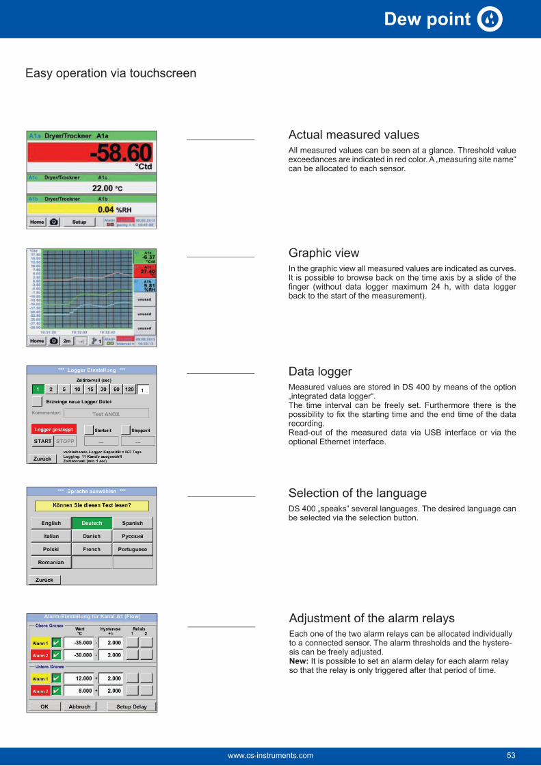
Easy operation via touchscreen
Actual measured valuesAll measured values can be seen at a glance. Threshold value exceedances are indicated in red color. A „measuring site name“ can be allocated to each sensor.
Graphic viewIn the graphic view all measured values are indicated as curves.It is possible to browse back on the time axis by a slide of the finger (without data logger maximum 24 h, with data logger back to the start of the measurement).
Data loggerMeasured values are stored in DS 400 by means of the option „integrated data logger“.The time interval can be freely set. Furthermore there is the possibility to fix the starting time and the end time of the data recording.Read-out of the measured data via USB interface or via the optional Ethernet interface.
Selection of the languageDS 400 „speaks“ several languages. The desired language can be selected via the selection button.
Adjustment of the alarm relaysEach one of the two alarm relays can be allocated individually to a connected sensor. The alarm thresholds and the hystere-sis can be freely adjusted. New: It is possible to set an alarm delay for each alarm relay so that the relay is only triggered after that period of time.
53www.cs-instruments.com 53
Dew point
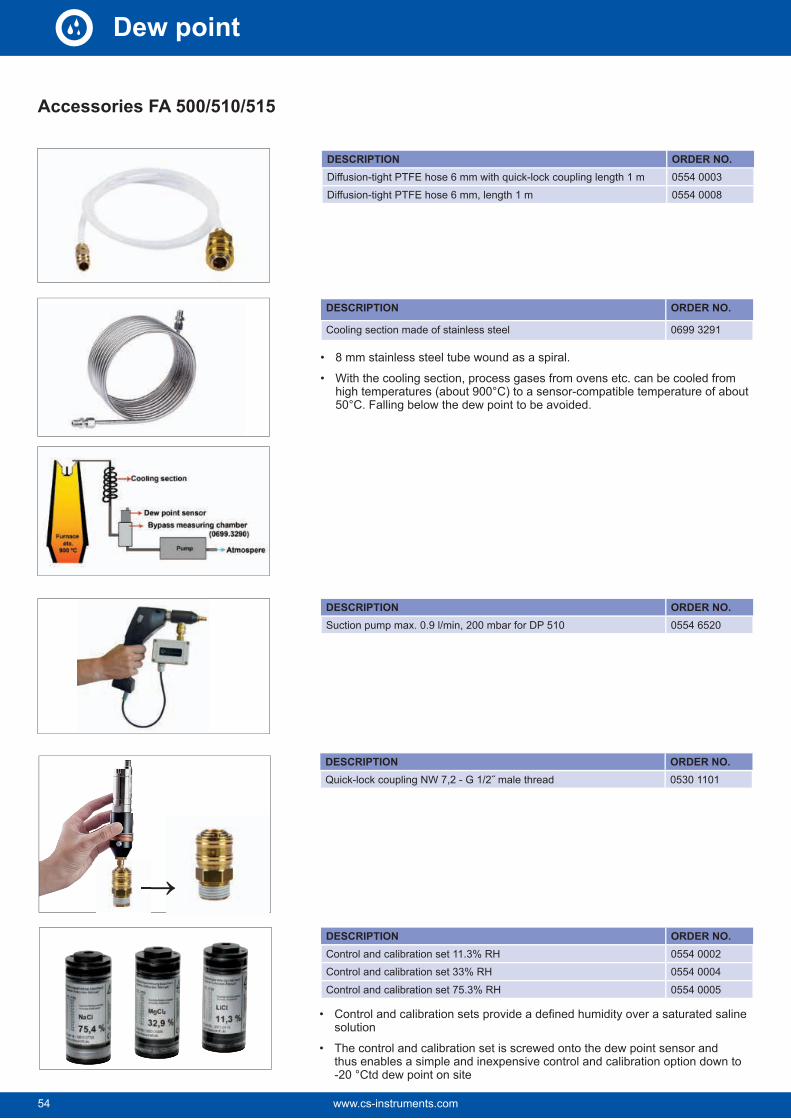
54
Accessories FA 500/510/515
DESCRIPTION ORDER NO.0554 00030554 0008
DESCRIPTION ORDER NO.
Cooling section made of stainless steel 0699 3291
DESCRIPTION ORDER NO.0530 1101
DESCRIPTION ORDER NO.Control and calibration set 11.3% RH 0554 0002Control and calibration set 33% RH 0554 0004Control and calibration set 75.3% RH 0554 0005
• solution
• The control and calibration set is screwed onto the dew point sensor and thus enables a simple and inexpensive control and calibration option down to -20 °Ctd dew point on site
• 8 mm stainless steel tube wound as a spiral.
• With the cooling section, process gases from ovens etc. can be cooled from high temperatures (about 900°C) to a sensor-compatible temperature of about 50°C. Falling below the dew point to be avoided.
DESCRIPTION ORDER NO.Suction pump max. 0.9 l/min, 200 mbar for DP 510 0554 6520
www.cs-instruments.com54
Dew point

Accessories FA 500/510/515
DESCRIPTION ORDER NO.Dry container for CS dew point sensors 0699 2500
DESCRIPTION ORDER NO.Connection cable for VA/FA series, 5 m 0553 0104Connection cable for VA/FA sensors, 10 m 0553 0105
Connection cable for VA/FA series, 20 m 0553 0120
Connection cable for VA/FA series, 5 m shielded 0553 0129
Connection cable for VA/FA series, 10 m shielded 0553 0130
Cable for alarm/pulse output, with M12 plug, 5 m 0553 0106Cable for alarm/pulse output, with M12 plug, 10 m 0553 0107
DESCRIPTION ORDER NO.Adapter plug FA 515/Michell easidew valve connector DIN 43650 form C 8 mm
0 2000 1389
DESCRIPTION ORDER NO.Ethernet connection cable length 5 m, M12 plug x-coded (8 pin) to RJ 45 plug
0553 2503
Ethernet connection cable length 10 m, M12 plug x-coded (8 pin) to RJ 45 plug
0553 2504
• Guarantees sensor protection and quick adaption time. Recommended for storage of mobile sensors
DESCRIPTION ORDER NO.M12 plug for FA 500/510/515 0 2000 0082M12 plug 90° angled 0219 0060
55www.cs-instruments.com 55
Dew point

56
Accessories FA 550
DESCRIPTION ORDER NO.Connection cable 5 m with open ends 0553 0108Connection cable 10 m with open ends 0553 0109
DESCRIPTION ORDER NO.PNG cable screwing - for standard 0553 0552
DESCRIPTION ORDER NO.AC adapter plug 100-240 VAC/24 V for VA/FA 5xx 0554 0109
Accessories for all FA 5xxDESCRIPTION ORDER NO.Mains unit in wall housing for maximum 2 sensors of the series VA/FA 5xx, 100-240 V, 23 VA, 50-60 Hz / 24 VDC, 0.35 A
0554 0110
DESCRIPTION ORDER NO.CS Service Software incl. PC connection set, USB connection and interface adapter to the sensor
0554 2007
USB
Power supply
AdapterFA 550
www.cs-instruments.com56
Dew point

Measuring chambers
DESCRIPTION ORDER NO.Standard measuring chamber for compressed air 0699 3390
DESCRIPTION ORDER NO.Stainless steel measuring chamber for compressed air up to 50 bar 0699 3292
DESCRIPTION ORDER NO.High pressure measuring chamber for compressed air up to 350 bar 0699 3590
DESCRIPTION ORDER NO.Stainless steel bypass measuring chamber for dew point measurement in gases under pressure
0699 3290
• Applicable for 2...16 bar• Process connection: Plug nipple NW 7.2 (Parker series 26) or G 1/4" female
thread when using without plug nipple• Sensor connection: G 1/2" female thread• Gives 2-3 liters / min of process air to the environment• The copper capillary relaxes the compressed air and prevents the backflow of
moisture from the ambient air into the measuring chamber
• Applicable for 30...350 bar• Process connection: G 1/4" female thread • Sensor connection: G 1/2" female thread• Emits 2-3 litres/min of process air to the environment via a fine nozzle• Via the high-pressure valve, the amount of air for sampling can be adjusted
individually depending on the pressure level. The process air is released to the environment via the sinter filter
• Applicable for -1...350 bar• Process connection: G 1/4" female thread gas inlet and G 1/4" female thread
gas outlet• Sensor connection: G 1/2" female thread• The flow of at least 2 liters / min of gas must be ensured by the customer
• Applicable for 2...50 bar• Process connection: G1/4" female thread• Sensor connection: G 1/2" female thread• Gives 2-3 liters / min of process air to the environment
57www.cs-instruments.com 57
Dew point

58
Measuring chambers
DESCRIPTION ORDER NO.Measuring chamber for atmospheric dew point 0699 3690
DESCRIPTION ORDER NO.Measuring chamber for granulate dryers and gases 0699 3490
• Applicable for 2...16 bar• Process connection: Plug nipple NW 7.2 (Parker series 26) or G 1/4" female
thread when using without plug nipple• Sensor connection: G 1/2" female thread• Gives 2-3 liters / min of process air to the environment• The throttle valve in front of the measuring chamber relaxes the compressed
air to atmospheric pressure in the measuring chamber. The manometer inte-grated in the measuring chamber indicates the overpressure to the atmo-sphere
• Applicable for -1...16 bar• Process connection: Plug connection for 6 mm hose at inlet and outlet or G
1/4" female thread when using without plug connections• Sensor connection: G 1/2" female thread• The flow of at least 2 liters / min of air / gas must be ensured by the customer
www.cs-instruments.com58
Dew point

Notes
59www.cs-instruments.com 59
Dew point

60
Control and calibration setControl and calibration sets provide a defined humidity over a saturated saline solu-tion.
The control and calibration set is screwed onto the dew point sensor and therefore enables an easy and low-priced possibility for on-site control and calibration down to -20 °C dew point.
Calibration range: from -80 to 20 °Ctd -Accuracy of the DKD reference: 0.1 °Ctd
DESCRIPTION ORDER NO.0699 3333
Precision calibration in the range -80...20 °Ctd, °Ctd points freely selectable 0700 7710
Control and calibration set 11.3% RH 0554 0002
Control and calibration set 33% RH 0554 0004
Control and calibration set 75.3% RH 0554 0005
0699 3396
Replacement unit for the period of re-calibration 0699 3900
Pressure dew point replacement sensor from our device pool including precision 0699 3990
Calibration of dew point sensorsThe calibration range for dew point sensors is from -80 °Ctd...20 °Ctd
Both dew point sensors from us and from other manufacturers can be calibrated. High precision reference measuring devices with DKD or BAM certificate guarantee an accuracy of up to 0.1 °C dew point.
Special feature:Due to the digital data transmission, only the dew point sensor has to be calibrated. The display devices remain wired on site.
www.cs-instruments.com60
Dew point

CS Service Software
• Scaling of the 4...20 mA analogue output
• Assignment of the parameter to the analogue output (e.g. 4...20 mA = 0...10 g/m³)
• Available units: °Ctd, °Ftd, g/m³, mg/m³, ppmv/v, g/kg
• -bration
• One-point calibration (adjustment) of the sensors in the process. This requires a reference device
• Update of the sensor software (Firmware)
• Modbus settings as Modbus-ID, Baud rate, Stopbit, Parity
With the CS service software including the USB Modbus interface adapter, the FA 510 / FA 515 / FA 500 dew point sensors can be con-figured via laptop / PC. The following settings can be made via CS Service Software:
DESCRIPTION ORDER NO.CS Service Software incl. PC connection set, USB connection and interface adapter to the sensor
0554 2007
61www.cs-instruments.com 61
Dew point

62
Today, compressed air is an essential and reliable source of energy from modern production processes.
-ments are made on the compressed air. The compliance with
the basic prerequisite for a permanently trouble-free system operation for every process.
Especially for moisture measurement or dew point / pressure dew point measurement in compressed air and gases, we have developed the DS 400 measuring device with many new advantages.
Dew point measurement in compressed air systems
www.cs-instruments.com62
Dew point

Usually, compressed air is generated from ambient air which must be aspi-rated, compressed by using pistons or screw compressors and which must then be dried more or less strongly.
The aim is to produce dry and oil-free compressed air which is low in dust par-ticles with the smallest possible effort. Residual oil and dust particles can be removed by means of complex filter sys-tems.However, moisture must be reduced by means of dryers (refrigeration dryers, membrane dryers, adsorption dryers and so on) which ideally work in a controlled manner independent of any load.
How does water get into compressed air?
Air is able to bind more water vapour the higher the temperature and the larger the volume. Conversely, if the air is compressed, the capacity to bind water vapour is reduced.
A compressor compresses atmospheric ambient air into a fraction of its original volume. At a certain point of the com-pression process the water content of the air exceeds the decreasing ability of the air to bind water. The air is saturated and part of the water drops out as con-densate.By means of an additional decrease of the temperature even more water will condensate.
This means that the relative humidity on the output of a compressor will always be at 100 % and that there will be additional water drops in the outgoing air.
The amount of liquid which drops out under pressure can be large. For exam-ple, a 30 kW compressor thus releases approximately 20 litres into the com-pressed air line at a humidity level of 60 % and an ambient temperature of 20 °C in eight hours. In case of big compres-sors this value will be much higher.
Effects of the moisture content
Depending on the application different demands are made on the compressed air. For each process the observance of a certain moisture content is the condi-tion for a durably failure-free functioning of the whole system.
Most of the compressed air lines are made from steel or non zinc-coated steel. Since the corrosion speed strongly increases from a relative humidity of 50 % this value should not be exceeded in any case.
In the course of time, high moisture will lead to a corrosion in case of non zinc-coated lines. The rust gradually chips off and moves to the sampling points. This leads e. g. to blocked nozzles, defective control elements and production stops.
Expensive repairs and short mainte-nance intervals are inevitable. In addi-tion to problems with corrosion and the described results the moisture content has direct influence on the quality of the final products.
Wich problems may arise in case of too high moisture?
In the following please find some of the most occurring samples:
• Hygroscopic products (spices,
during transport by the pneu-matic conveyor system
• Bubbles are formed during paint-ing and coating processes
• Boreholes can clog up from dust being carried
• Control valves freeze over in winter in unheated halls10610101
Tasks of dryers
Different types of dryers are used in practice in order to control the problems of moisture levels that are too high.
In compressed air technology, the pres-sure dew point is the parameter for indi-cating the dryness of compressed air. The pressure dew point is the tempera-ture at which the moisture which is con-tained in the compressed air condenses to form liquid water (also saturation, 100% relative humidity).
The lower the pressure dew point tem-perature, the smaller the amount of water vapour contained in the compressed air.
63www.cs-instruments.com 63
Dew point

64
Refrigeration dryer for dew point
There are different types of compressed air dryers; refrigeration dryers or adsorp-tion dryers are the most commonly used ones.
Refrigeration dryers cool down the com-pressed air to approx. 2 to 5 °C. In this case, the pressure dew point is also 2 to 5 °C. The excess water vapour con-denses and precipitates.
After that the air is again heated up to room temperature.
The refrigeration compressed air dryers are monitored in most cases only by a display of the cooling temperature. A sta-tionary humidity monitor is hitherto only installed in large systems or in particu-larly important applications.
However, the display of the cooling tem-perature alone is not sufficient. Even if the cooling temperature seems to be OK, the following errors can cause an exces-sive pressure dew point:
• Condensate in the refrigeration dryer is not drained off (conden-
• Compressed air bypass in the refrigeration dryer (close and cor-rode heat exchanger pipes and
bypass lines
• A failure of the refrigeration dryer inevitably leads to considerable problems with condensate in the compressed air line
It is especially problematic (besides the already listed problems), if the conden-sate can concentrate in blind lines and does not drain off automatically. Conden-sate in blind lines can only be removed again by means of considerable efforts or dried and drained off by means of an extremely large amount of compressed air.
This often leads to increased dew point values at very low consumption rates, without the refrigeration dryer show-ing any obvious problems. In this case, it is quite difficult for the person who is responsible for compressed air to find out the reason for the increased dew point values or in extreme cases for the con-densate in the long-term.
Adsorption dryers for typical dew points -30...-40 °Ctd.
The functioning of the adsorption dryer is based on the principle of the attraction between the two masses. Water vapor is bound (absorbed) at the surface of a desiccant.
Effective adsorption dryers are able to dry compressed air down to a pressure dew point of -40 °C and lower.
Regenerative adsorption dryer exist of two tanks which are filled with desiccant. In different procedures there is one tank regenerated cold resp. warm while the other one dries the operation air.
Depending on the procedure and the operating conditions the desiccant has to be exchanged in cycles of three to five years.
Certain operating conditions lead to a shortening of the life span of the des-iccant:
• Overload on compressed air side due to excessive compressed air consumption
• Poor pre-separation of condensate• Oily air• Regeneration times of the individual
tanks too long
New: DS 400 dew point measurement with alarm ensures process reliability
Unique worldwide with 3.5" graphic display with touch screen and print function.
An alarm delay can be set for each relay. This grants that only really long-term threshold value exceedances are indicated. Additionally every alarm can be reset.
www.cs-instruments.com64
Dew point

The dew point set DS 400 consists of the chart recorder DS 400 and the dew point sensor FA 510 including measur-ing chamber for the pressure dew point measurement of compressed air and gases up to 16/50/350 bar.
For pressures of more than 16 bar, please use the high-pressure measuring chamber.
The heart of the dew point sensor is the worldwide proven humidity sensor. In order to get quick and accurate mea-surements it is necessary that the humid-ity sensor is continuously flown by the gas (compressed air) to be measured. For this purpose a defined volume flow is blown out at a certain pressure via a capillary line.
The measuring chamber can be con-nected to the sampling point without any large installation efforts by means of the standard plug nipple for compressed air lines.The big difference to customary paper-less chart recorders is reflected in the simplicity of DS 400 on initiation and evaluation of the measured data.
The intuitive operation with the 3.5" touch screen graphic display with zoom func-tion and print key is the only one of its kind in the world in this price category. By means of the graphic display with zoom function the drying procedure resp. the dew point curve can be seen at a glance and stored in the data logger. So the user can take a look at the stored measuring curves also without any computer at any time on site. This grants a quick and easy analysis of the drying behavior.
By means of the print key the actual screen can be stored as an image file to the internal SD card or to a USB stick and printed out at the computer without any additional software.
Ideal for documentation of the measured values/measurement curves on site.
Colored measurement curves can be sent by e-mail as image files or inte-grated into a service report.
The internal data logger enables the storage of the measured data for several years. The measured data can be eval-uated on a USB stick of via Ethernet by means of the comfortable software CS Soft Basic.
Special features:
• 3.5" graphic display, intuitive operation via touch screen
• Zoom function for accurate analy-sis of measured values
• Colored measurement curves with names
• Mathematical calculation function for calculation of the dew point
• Print key: optional indications can be stored as image files directly on a USB stick and sent by e-mail without any software
• 2 alarm contacts for threshold value exceedance
• Freely adjustable alarm delay for both alarm contacts with reset function
• Up to 4 sensor inputs for: addi-tional dew point, pressure, tem-perature, flow meters, electrical effective power meters, optional third-party sensors can be con-nected: Pt 100/ 1000, 0/4…20 mA, 0-1/10 V, Modbus, pulse
• Integrated data logger 8 GB• USB, Ethernet interface, RS 485 /
Modbus• Web server
65www.cs-instruments.com 65
Dew point

VA 570 -
Special mechanical features:
• Robust impact-proof aluminium die cast housing for the outdoor area IP 67
• All wetted parts made from stainless steel 1.4571
• On request with DVGW approval for natural gas (up to 16 bar)
• Pressure range up to 16 bar, special version up to 40 bar
• Temperature range up to 180 °C
• No moveable parts, no wear
• Sensor tip very robust, easy to clean
• Housing rotatable, display rotatable by 180°
Special measurement technology features:
• 4 values on the display: Flow, total consumption, velocity, tem-perature. Units freely adjustable
• All measured values, settings such as gas type, inner diameter, serial number and so on can be accessed via Modbus-RTU
• Comprehensive diagnostic functions readable on the display or remote access via Modbus such as calibration cycle, error codes, serial number
•
• Standard version accuracy 1.5% of m.v. ± 0.3% of f.s.
• Precision version accuracy 1.0% of m.v. ± 0.3% of f.s
• Measuring span of 1 : 1000 (0.1 up to 224 m/s)
• 500, PC service software on-site
• Gas type (air, nitrogen, oxygen, argon and so on) freely adjust-able via PC service software or external device DS 400, DS 500, PI 500
• Reference conditions °C and mbar/hPa freely adjustable
•
• Pressure loss negligible
Version with pipe thread R thread or NPT threadFlange version
VA 570 is supplied with an integrated measuring section. The measuring sections are available in flanged version or with R resp. NPT thread.
A special feature is the removable measuring head. So the measuring unit can be removed easily and quickly for calibration or cleaning purposes without having to dismount the measuring section intricately. During this period the measuring section is sealed by a closing cap (accessory).
The screwing with a centring device is designed such that the sensor is positioned accurately in the centre when screwing it into the measuring section; furthermore, it enables an exact positioning in the flow direction. This eliminates unnecessary measuring faults.
The sensor can be removed and cleaned
Approvals:II 2 G Ex db IIC T4 Gb
II 2 D Ex tb IIIC T90 °C Db
Flow
66 www.cs-instruments.com

For further accessories refer to pages 88 to 92
Optional: Connection to different Bus systems
There are different options available for connection to modern Bus systems:
• Ethernet interface (Modbus-TCP) / PoE
• M-BUS
• Modbus-RTU
•
•
• HART (in process)
P R O F I
N E T
P R O F I
B U S
Ethernet Modbus TCP
M12 Ethernet port, x-coded
m³/h (cfm) m³/h (cfm) m³/h (cfm) m³/h (cfm) m³/h (cfm) m³/h (cfm) m³/h (cfm) m³/h (cfm)
Reference conditions DIN 1945 / ISO 1217: 20 °C, 1000 mbar
AirLow-Speed (50 m/s) 20 (14) 45 (25) 75 (45) 140 (80) 195 (115) 320 (190) 550 (325) 765 (450)Standard (92.7 m/s) 45 (25) 85 (50) 145 (85) 265 (155) 365 (215) 600 (350) 1025 (600) 1420 (835)Max (185 m/s) 90 (50) 175 (100) 290 (170) 530 (310) 730 (430) 1195 (700) 2050 (1205) 2840 (1670)High-Speed (224 m/s) 110(60) 215 (125) 355 (210) 640 (375) 885 (520) 1450 (850) 2480 (1460) 3440 (2025)
Setting to DIN 1343: 0 °C, 1013.25 mbar
Low-Speed (50 m/s) 35 (20) 75 (40) 120 (70) 220 (130) 305 (180) 505 (295) 865 (510) 1200 (705)Standard (92.7 m/s) 70 (40) 135 (80) 230 (135) 415 (245) 570 (335) 935 (550) 1605 (945) 2225 (1310)Max (185 m/s) 140 (80) 275 (160) 460 (270) 830 (485) 1140 (670) 1870 (1100) 3205 (1885) 4440 (2615)High-Speed (224 m/s) 170 (100) 335 (195) 555 (325) 1005 (590) 1385 (815) 2265 (1330) 3880 (2285) 5380 (3165)
Carbondi-oxide
Low-Speed (50 m/s) 20 (14) 45 (25) 75 (45) 140 (80) 195 (115) 320 (185) 545 (320) 760 (445)Standard (92.7 m/s) 45 (25) 85 (50) 145 (85) 260 (155) 360 (210) 590 (345) 1015 (595) 1405 (825)Max (185 m/s) 90 (50) 175 (100) 290 (170) 525 (305) 720 (425) 1185 (695) 2030 (1190) 2810 (1655)High-Speed (224 m/s) 105 (60) 210 (125) 350 (205) 635 (370) 875 (515) 1430 (840) 2455 (1445) 3405 (2000)
NitrogenLow-Speed (50 m/s) 20 (13) 40 (25) 70 (40) 130 (75) 180 (105) 295 (175) 505 (300) 705 (415)Standard (92.7 m/s) 40 (20) 80 (45) 135 (75) 240 (140) 335 (195) 550 (320) 945 (555) 1305 (770)Max (185 m/s) 80 (45) 160 (95) 270 (155) 485 (285) 670 (395) 1100 (645) 1885 (1110) 2610 (1535)High-Speed (224 m/s) 100 (55) 195 (115) 325 (190) 590 (345) 815 (475) 1330 (780) 2280 (1340) 3165 (1860)
Oxygen Low-Speed (50 m/s) 20 (13) 45 (25) 75 (40) 135 (80) 185 (110) 305 (180) 525 (310) 730 (430)Standard (92.7 m/s) 40 (25) 80 (45) 140 (80) 250 (145) 345 (205) 570 (335) 980 (575) 1355 (795)Max (185 m/s) 85 (50) 165 (95) 280 (165) 505 (295) 695 (410) 1140 (670) 1955 (1150) 2710 (1590)High-Speed (224 m/s) 105 (60) 205 (120) 340 (200) 610 (360) 845 (495) 1380 (810) 2365 (1390) 3280 (1930)
Nitrous oxide
Low-Speed (50 m/s) 20 (14) 45 (25) 75 (45) 140 (80) 190 (110) 315 (185) 540 (320) 750 (440)Standard (92.7 m/s) 40 (25) 85 (50) 140 (85) 260 (150) 355 (210) 585 (345) 1005 (590) 1395 (820)Max (185 m/s) 85 (50) 170 (100) 285 (170) 520 (305) 715 (420) 1170 (690) 2010 (1180) 2785 (1640)High-Speed (224 m/s) 105 (60) 210 (120) 345 (205) 630 (370) 865 (510) 1420 (835) 2435 (1430) 3375 (1985)
Natural Low-Speed (50 m/s) 14,4 (8) 25 (15) 45 (25) 85 (50) 115 (65) 190 (110) 325 (190) 450 (265)Standard (92.7 m/s) 25 (15) 50 (30) 85 (50) 155 (90) 215 (125) 355 (205) 605 (355) 840 (495) Max (185 m/s) 50 (30) 105 (60) 170 (100) 310 (185) 430 (250) 705 (415) 1210 (710) 1680 (985)High-Speed (224 m/s) 65 (35) 125 (70) 210 (120) 380 (220) 520 (305) 855 (500) 1465 (865) 2035 (1195)
Measuring range - Flow VA 570
HART
Flow
67www.cs-instruments.com

VA 570 - Example order code VA 570:0695 0570_A1_B1_C1_D1_E1_F1_G1_H1_I1_J1_K1_L1_M1_R1
Male thread measuring sectionA1 R male threadA2 NPT male threadA3 Flange DIN EN 1092-1A4 Flange ANSI 16.5 Class 150 lbsA5 Flange ANSI 16.5 Class 300 lbs
Display optionB1 with integrated displayB2 without display
Option signal outputs / bus connection
C1 2 units 4...20 mA analogue output (electrically isolated), pulse output, RS 485 (Modbus-RTU)
C2 -cally isolated), pulse output, RS 485 (Modbus-RTU)
C4 1 x 4…20 mA analogue output (not electrically isolated), pulse output, RS 485 (Modbus-RTU)
C5Ethernet interface (Modbus / TCP), 1 x 4...20 mA ana-logue output (not electrically isolated), pulse output, RS 485 (Modbus-RTU)
C8 M-Bus, 1 x 4…20 mA analogue output (not electrically isolated), pulse output, RS 485 (Modbus-RTU)
C9Ethernet interface PoE (Power over Ethernet) (Modbus/TCP), 1 x 4…20 mA analogue output (not electrically isolated), pulse output, RS 485 (Modbus-RTU)
Adjustment/calibration
D1 constantD2 Real gas adjustment in the gas type selected below
Gas typeE1 Compressed airE2 Nitrogen (N2)E3 Argon (Ar)E4 Carbon dioxide (CO2)E5 Oxygen (O2)E6 Nitrous oxide (N2O)E7 Natural gas (NG)E8 Helium (He)E9 Propane (C3H8)E10 Methane (CH4)E11 Biogas (methane 50% : CO2 50%)E12 Hydrogen (H2)E90 Further gas / please indicate gas type (on request)E91 Gas mixture / please indicate mixture ratio (on request)
Reference standardF1 20 °C, 1000 mbarF2 0 °C, 1013.25 mbarF3 15 °C, 981 mbarF4 15 °C, 1013.25 mbar
Maximum pressureG1 16 barG2 40 bar
Surface conditonH1 standard version
H2 Special cleaning - oil and grease free (e. g. for oxygen applications and so on)
H3 Silicone-free version including special cleaning oil- and grease-free
Accuracy classI1 ± 1.5% of the measured value ± 0.3% f.s. (standard)I2 ± 1% of the measured value ± 0.3% f.s. (precision)
Maximum gas temperature on the sensor tipJ1 up to 120 °C gas temperature (only for ATEX version)J2 up to 180 °C gas temperature (standard)
ApprovalsK1 Non-explosive area - no approval
K2 ATEX II 2G Ex d IIC T4ATEX II 2D Ex tb IIC T90 °C, Db
K3 DVGW approval for natural gas (max. pressure 16 bar)
M1 Max version (185 m/s)M2 Low-speed version (50 m/s)M3 Standard version (92,7 m/s)M4 High-speed version (224 m/s)
Special measuring range
R1 Special measuring range (please specify when placing order)
Flow
68 www.cs-instruments.com

Order no. VA 570
DESCRIPTION ORDER NO.
0695 0570+ order code A_…R_
0695 0571
0695 0572
0695 0573
0695 0574
0695 0575
0695 2570
0695 2571
0695 2572
0695 2573
0695 2574
0695 2575
0695 2576
0695 2577
Further accessories:
Closing cap for measuring section in aluminium 0190 0001
Closing cap for measuring section stainless steel 1.4404 0190 0002
Connection cable for probes 5 m with open ends 0553 0108
Connection cable for probes 10 m with open ends 0553 0109
Ethernet connection cable length 5 m, M12 plug x-coded (8 pin) to RJ 45 plug
0553 2503
Ethernet connection cable length 10 m, M12 plug x-coded (8 pin) to RJ 45 plug
0553 2504
Mains unit in wall housing for maximum 2 sensors of the series VA/FA 5xx, 100-240 V, 23 VA, 50-60 Hz / 24 VDC, 0.35 A
0554 0110
VA sensors3200 0001
Additional calibration point (point freely selectable) 0700 7720
CS Service Software VA 550 incl. interface cable to PC -
tion of VA 550
0554 2007
PNG cable screwing - standard VA 550/570 0553 0552
PNG cable screwing - for ATEX version VA 550/570 0553 0551
TECHNICAL DATA VA 570Measuring range VA 570: up to 50 Nm/s, low-speed version*
up to 92.7 Nm/s, standard version*up to 185 Nm/s, max. version*up to 224 Nm/s, high-speed version*
pipe diameters and gases, see table
* All measured values related to DIN 1343 standard conditions 0° and 1013 mbar ex works
Accuracy:Accuracy class(o. M. V. = of measured
± 1.5% of m.v. ± 0.3 % of f.s.on request:± 1.0% of m.v. ± 0.3 % of f.s.
Accuracy indications: relative to ambient temperature 22 °C ± 2 °C, system pressure 6 bar
Repeatability: 0.25% of m.v. in case of correct mounting (mounting aid, position, inlet section)
Measuring principle:Response time: t90 < 3 sOperating temperature range sensor tube/dis-play unit:
-40…180 °C standard version, sensor tube-20…70 °C display unit-20…120 °C for ATEX version
Adjustment possibilities via display, external hand-held device PI 500, PC Service Software, remote diagnosis:
Nm³/h, Nm³/min, Nl/min, l/s, ft/min, cfm, kg/h, kg/min, inner diameter, reference conditions ° C/° F, mbar/
volume suppression, scaling analogue output 4...20 mA, pulse/alarm, error codes etc.
Outputs: Standard: 1 x 4…20 mA analogue output (not electrically isolated), pulse output, RS 485 (Modbus-RTU)Optional: 2 x 4 ... 20 mA active,
Burden: < 500 OhmAdditional average value calculation:
for all parameters freely adjustable from 1 minute up to 1 day, e. g. 1/2 hours average value, average day value
Protection class: IP 67Material: Die-cast aluminum housing, sensor
tube stainless steel 1.4571Operating pressure: 16 bar, in special version 40 barPower supply: 18…36 VDC, 5 WApproval: ATEX II 2G Ex db IIC T4 Gb,
ATEX II 2D Ex tb IIC T90 °C, Db,DVGW
Flow
69www.cs-instruments.com
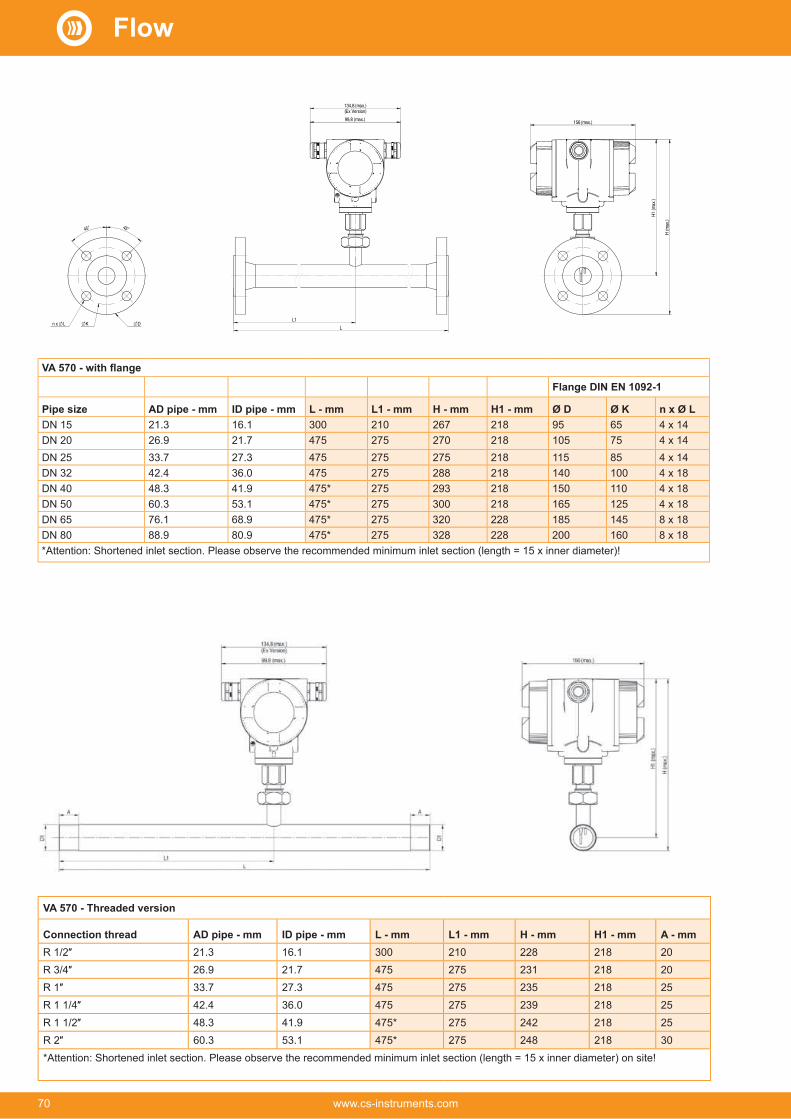
45° 45°
K D n x LL1
L
134,8(max.)(Ex Version)
99,8 (max.)
H1 (m
ax.)
H (m
ax.)
156(max.)
Flange DIN EN 1092-1
Pipe size AD pipe - mm ID pipe - mm L - mm L1 - mm H - mm H1 - mm Ø D Ø K n x Ø LDN 15 21.3 16.1 300 210 267 218 95 65 4 x 14DN 20 26.9 21.7 475 275 270 218 105 75 4 x 14DN 25 33.7 27.3 475 275 275 218 115 85 4 x 14DN 32 42.4 36.0 475 275 288 218 140 100 4 x 18DN 40 48.3 41.9 475* 275 293 218 150 110 4 x 18DN 50 60.3 53.1 475* 275 300 218 165 125 4 x 18DN 65 76.1 68.9 475* 275 320 228 185 145 8 x 18DN 80 88.9 80.9 475* 275 328 228 200 160 8 x 18*Attention: Shortened inlet section. Please observe the recommended minimum inlet section (length = 15 x inner diameter)!
VA 570 - Threaded version
Connection thread AD pipe - mm ID pipe - mm L - mm L1 - mm H - mm H1 - mm A - mm21.3 16.1 300 210 228 218 2026.9 21.7 475 275 231 218 2033.7 27.3 475 275 235 218 2542.4 36.0 475 275 239 218 2548.3 41.9 475* 275 242 218 2560.3 53.1 475* 275 248 218 30
*Attention: Shortened inlet section. Please observe the recommended minimum inlet section (length = 15 x inner diameter) on site!
Flow
70 www.cs-instruments.com

Notes
Flow
71www.cs-instruments.com

VA 550 - Flow meter insertion typeFlow sensor for installation in existing compressed air or gas line of 3/4" to DN 1000
Special mechanical features:
• Robust impact-proof aluminium die cast housing for the outdoor area IP 67
• All wetted parts made from stainless steel 1.4571
• Suitable as an insertion version for 3/4" to DN 1000
• On request with DVGW approval for natural gas (up to 16 bar)
• Pressure range up to 50 bar, special version up to 100 bar
• Temperature range up to 180 °C
• No moveable parts, no wear
• Sensor tip very robust, easy to clean
• Easy installation and removal under pressure via 1/2" ball valve
• Housing rotatable, display rotatable by 180°
• Safety ring for installation and removal under pressure
• Depth scale for precise installation
Housing IP 67 Outputs:4…20 mA, pulse, Modbus, M-Bus, Profi Bus, Ethernet, HART
Housing rotatable, display 180° rotatable (on the head). Settings can be modified via display, flow meter can be reset
Special measurement technology features:
• 4 values on the display: Flow, total consumption, velocity, tem-perature. Units freely adjustable
• All measured values, settings such as gas type, inner diameter, serial number and so on can be accessed via Modbus-RTU
• Comprehensive diagnostic functions readable on the display or remote access via Modbus such as calibration cycle, error codes, serial number
•
• Standard version accuracy 1.5% of m.v. ± 0.3% of f.s.
• Precision version accuracy 1.0% of m.v. ± 0.3% of f.s
• Measuring span of 1 : 1000 (0.1 up to 224 m/s)
• 500, PC service software on-site
• Gas type (air, nitrogen, oxygen, argon and so on) freely adjust-able via PC service software or external device DS 400, DS 500, PI 500
• Reference conditions °C and mbar/hPa freely adjustable
•
• Pressure loss negligible
All wetted parts made from stain-less steel 1.4571
Advantages of optical keys:The sensor can also be config-ured in the ATEX area, without the housing needing to be opened.
Approvals:
II 2 G Ex db IIC T4 Gb
II 2 D Ex tb IIIC T90 °C Db
The sensor can be removed and cleaned
Flow
72 www.cs-instruments.com

For further accessories refer to pages 88 to 92
Easy mounting/dismounting of VA 550 under pressure - without disconnection of the line - without emptying the line
Optional: Connection to different Bus systems
There are different options available for connection to modern Bus systems:
• Ethernet interface (Modbus-TCP) / PoE
• M-BUS
• Modbus-RTU
•
•
• HART (in process)
P R O F I
N E T
P R O F I
B U S
Ethernet Modbus TCP
M12 Ethernet port, x-coded
If there is no suitable measuring site with 1/2" ball valve, there are two simple possibilities to set up a measuring site:
A Weld on a 1/2" screw neck and screw on a 1/2" ball valve
B Mount spot drilling collar including ball valve
By means of the drilling jig, it is possible to drill under pres-sure through the 1/2" ball valve into the existing pipe. The drilling chips are collected in a filter. Then the probe can be mounted.
Drill under pressure with the CS drilling jig
A Screw neck B Spot drilling collars
Installation depth = x + ydA = outer diameterx = dA2
yx
Order no.: 3300 0006 Order no.: see page 92 Order no.: 0530 1108
180
170
160
Engraved depth scale for precise installation
dA
HART
Flow
73www.cs-instruments.com

VA 550 - Flow meter insertion meterExample order code VA 550:0695 0550_A1_B1_C1_D1_E1_F1_G1_H1_I1_J1_K1_L1_M1_R1
A1 Standard version (92,7 m/s)A2 Max version (185 m/s)A3 High-speed version (224 m/s)A4 Low-speed version (50 m/s)
Screw-in threadB1 G 1/2" male threadB2 1/2" NPT male threadB3 PT 1/2” male thread
Installation length / shaft lengthC1 220 mmC2 300 mmC3 400 mmC4 500 mmC5 600 mmC6 700 mm (not with ATEX)C7 160 mmC8 1000 mm (not with ATEX)C9 1500 mm (not with ATEX)
Display optionD1 with integrated displayD2 without display
Signal outputs / bus connection option
E1 2 units 4...20 mA analogue output (electrically isolated), pulse output, RS 485 (Modbus-RTU)
E2 -cally isolated), pulse output, RS 485 (Modbus-RTU)
E4 1 x 4…20 mA analogue output (not electrically isolated), pulse output, RS 485 (Modbus-RTU)
E5Ethernet interface (Modbus / TCP), 1 x 4...20 mA ana-logue output (not electrically isolated), pulse output, RS 485 (Modbus-RTU)
E7 2 units 4...20 mA analogue output passive, pulse output RS 485 (Modbus-RTU)
E8 M-Bus, 1 x 4…20 mA analogue output (not electrically isolated), pulse output, RS 485 (Modbus-RTU)
E9Ethernet interface PoE (Power over Ethernet) (Modbus/TCP), 1 x 4…20 mA analogue output (not electrically isolated), pulse output, RS 485 (Modbus-RTU)
Adjustment / calibration
F1 constantF2 Real gas adjustment in the gas type selected below
Gas typeG1 Compressed airG2 Nitrogen (N2)G3 Argon (Ar)G4 Carbon dioxide (CO2)G5 Oxygen (O2)G6 Nitrous oxide (N2O)G7 Natural gas (NG)G8 Helium (He) (real gas adjustment F2 required)G9 Propane (C3H8) (real gas adjustment F2 required)G10 Methane (CH4)G11 Biogas (methane 50% : CO2 50%)G12 Hydrogen (H2) (real gas adjustment F2 required)G90 Further gas / please indicate gas type (on request)G91 Gas mixture / please indicate mixture ratio (on request)
Maximum pressure (more than 10 bar high-pressure protec-
H1 50 barH2 100 barH3 16 bar
Surface conditonI1 standard version
I2 special cleaning - oil and grease free (e.g. for oxygen applications and so on)
I3 Silicone-free version including special cleaning oil- and grease-free
Accuracy classJ1 ± 1.5% of the measured value ± 0.3% f.s. (standard)J2 ± 1% of the measured value ± 0.3% f.s. (precision)
Maximum gas temperature on the sensor tipK1 up to 120 °C gas temperature (only for ATEX version)K2 up to 180 °C gas temperature (standard)
ApprovalsL1 Non-explosive area - no approval
L2 ATEX II 2G Ex db IIC T4 GbATEX II 2D Ex tb IIC T90 °C, Db
L3 DVGW approval for natural gas (max. pressure 16 bar)
Reference standardM1 20 °C, 1000 mbarM2 0 °C, 1013.25 mbar M3 15 °C, 981 mbarM4 15 °C, 1013.25 mbar
Special measuring range
R1 Special measuring range (please specify when placing order)
Flow
74 www.cs-instruments.com

DESCRIPTION ORDER NO.VA 550 Flow meter, measuring head in robust aluminium die casting housing
0695 0550 + Order code A_…R_
TECHNICAL DATA VA 550Measuring range VA 550: up to 50 Nm/s, low-speed version*
up to 92.7 Nm/s, standard version*up to 185 Nm/s, max. version*up to 224 Nm/s, high-speed version*
pipe diameters and gases, see table
* All measured values related to DIN 1343 standard conditions 0° and 1013 mbar ex works
Accuracy:Accuracy class(o. M. V. = of measured value)(o. F. S. = of full scale)
± 1.5 % of m.v. ± 0.3 % of f.s.on request:± 1.0 % of m.v. ± 0.3 % of f.s.
Accuracy indications: relative to ambient temperature 22 °C ± 2 °C, system pressure 6 bar
Repeatability: 0.25 % of m.v. in case of correct mounting (mounting aid, position, inlet section)
Measuring principle:Response time: t 90 < 3 sOperating temperature range sensor tube/dis-play unit:
-40…180 °C standard version, sensor tube-20…70 °C display unit-20…120 °C for ATEX version
Adjustment possibilities via display, external hand-held device PI 500, PC Service Software, remote diagnosis:
Nm³/h, Nm³/min, Nl/min, l/s, ft/min, cfm, kg/h, kg/min, inner diameter, reference conditions ° C/° F, mbar/hPa,
suppression, scaling analogue output 4...20 mA, pulse/alarm, error codes etc.
Outputs: Standard: 1 x 4…20 mA analogue output (electrically not isolated), pulse output,RS 485 (Modbus-RTU)Optional: 2 x 4...20 mA active, Modbus
M-BusBurden: < 500 ohmAdditional average value calculation:
for all parameters freely adjustable from 1 minute up to 1 day, e. g. 1/2 hours average value, average day value
Protection class: IP 67Material: Die-cast aluminum housing, sensor
tube stainless steel 1.4571Screw-in thread: G 1/2" ISO 228, NPT 1/2", R 1/2",
PT 1/2"Operating pressure VA 550:
50 bar, in special version 100 bar(with DVGW approval max. 16 bar)
Power supply: 18…36 VDC, 5 WApproval: ATEX II 2G Ex db IIC T4 Gb,
ATEX II 2D Ex tb IIC T90 °C, Db,DVGW
DESCRIPTION ORDER NO.Connection cable for probes 5 m with open ends 0553 0108Connection cable for probes 10 m with open ends 0553 0109Ethernet connection cable length 5 m, M12 plug x-coded (8 pin) to RJ 45 plug
0553 2503
Ethernet connection cable length 10 m, M12 plug x-coded (8 pin) to RJ 45 plug
0553 2504
Mains unit in wall housing for maximum 2 sensors of the series VA/FA 5xx, 100-240 V, 23 VA, 50-60 Hz / 24 VDC, 0.35 A
0554 0110
VA 500/5503200 0001
(point freely selectible)0700 7720
CS Service Software VA 550 incl. interface cable to PC -
tion of VA 550
0554 2007
High-pressure protection recommended for installation from 10 to 100 bar (for VA 550)
0530 1115
High-pressure protection recommended for installation from 10 to 16 bar DVGW (for VA 550)
0530 1116
PNG cable screwing - standard VA 550/570 0553 0552PNG cable screwing - for ATEX version VA 550/570 0553 0551
Further accessories:
Order no. VA 550
Installation/shaft lengthC1 220 441C2 300 521C3 400 621C4 500 721C5 600 821C7 160 381C8 1000 1221C8 1500 1721
Flow
75www.cs-instruments.com

VA 500 - Flow meter for compressed air and gases
Movable mount-ing thread G 1/2"
Safety ringØ 11.7 mm
Special features:
• Including temperature measurement
• RS 485 interface, Modbus-RTU as standard
• Integrated display for m³/h and m³
• Applicable from 1/2” to DN 1000
• Easy installation under pressure
• 4...20 mA analogue output for m³/h or m³/min
• Pulse output for m³ or M-Bus (op-tional)
• Inner diameter adjustable by means of keys
• Flow meter can be reset
• Adjustable by means of keypad on the display: Reference conditions, °C and mbar, 4...20 mA scaling, pulse weight
TECHNICAL DATA VA 500Parameters: m³/h, l/min (1000 mbar, 20 °C) in
case of compressed air or Nm³/h, Nl/min (1013 mbar, 0 °C) in case of gases
Units adjustable via keys at display:
m³/h, m³/min, l/min, l/s, ft/min, cfm, m/s, kg/h, kg/min, g/s, lb/min, lb/h
Adjustable via keypad: -tion, counter resettable
Sensor:Measured medium: Air, gasesGas types are adjustable over CS service software or CS data logger:
Air, nitrogen, argon, helium, CO2, oxygen, vacuum
Measuring range: See table page 77Accuracy: ± 1.5% of m.v. ± 0.3 % of f.s.
on request:± 1% of m.v. ± 0.3% of f.s.
Operating temperature: -30...110 °C sensor tube-20...+70 °C housing
Operating pressure: -1…50 bar (for pressure > 10 bar - order additional high-pressure protection)
Digital output: RS 485 interface, (Modbus-RTU), optional: Ethernet interface PoE, M-Bus
Analogue output: 4…20 mA for m³/h or l/minPulse output: 1 pulse per m³ or per litre electri-
cally isolated. Pulse weight can be set on the display. Alternatively, the pulse output can be used as an alarm
Supply: 18…36 VDC, 5 WBurden:Housing: Polycarbonate (IP 65)Sensor tube: Stainless steel, 1.4301
Installation length 220 mm, Ø 10 mm
Mounting thread:Ø housing: 65 mmMounting position: any
DESCRIPTION ORDER NO.
Standard (92.7 m/s), probe length 220 mm, without display0695 5001
Bi-directional measurement - includes 2 x 4…20 mA analo-gueue outputs and 2x pulse outputs. These do not apply to Ethernet (PoE) and M-Bus
Z695 6000
Options for VA 500:Display Z695 5000Max version (185 m/s) Z695 5003High-speed version (224 m/s) Z695 5002Low-speed version (50 m/s) Z695 50081% accuracy of m.v. ± 0.3 % of f.s. Z695 5005Ethernet interface for VA 500/520 and FA 500 Z695 5006Ethernet interface PoE for VA 500/520 and FA 500 Z695 5007M-Bus board for VA 500/520 and FA 500 Z695 5004Probe length 120 mm ZSL 0120Probe length 160 mm ZSL 0160Probe length 300 mm ZSL 0300Probe length 400 mm ZSL 0400Probe length 500 mm ZSL 0500Probe length 600 mm ZSL 0600
Z695 5015High-pressure protection recommended for installation from 10 to 50 bar (for VA 400/500)
0530 1105
-sors
3200 0001
Gas type:___ (specify gas type when placing order) Z695 5009Gas mixture:___ (specify gas mixture when placing order) Z695 5010Real gas adjustment 3200 0015Special cleaning oil and grease free (e.g. for oxygen appli-cations)
0699 4005
LABS and silicone-free version including cleaning oil and grease-free
0699 4007
Additional calibration curve stored in the sensor (can be selected via display)
Z695 5011
Z695 5012
Inner diameter adjustable via keypad
Option: Bi-directional measurement. Blue or green arrows in the dis-play indicate the direction of flow.A meter reading is available for each flow direction.
For further accessories refer to pages 88 to 92
Flow
76 www.cs-instruments.com

Simple installation and removal under pressure
Even under pressure, the flow probe VA 500 is mounted by means of a stan-dard 1/2" ball valve.During mounting and dismounting the safety ring avoids an uncontrolled ejec-tion of the probe which may be caused by the operating pressure.For the mounting into different pipe diam-eters, VA 500 is available in the follow-ing probe lengths: 120, 160, 220, 300, 400 mm.The flow probes are therefore suitable for being mounted into existing pipes with diameters of 1/2" to DN 300 upwards.The exact positioning of the sensor in the middle of the pipe is granted by means of the engraved depth scale.The maximum mounting depth corre-sponds to the respective probe length. (Probe length 220 mm = 220 mm max-imum mounting depth).
If there is no suitable measuring site with 1/2” ball valve, there are two easy ways to set up a measuring site:A Weld on a 1/2" screw neck and screw
on a 1/2" ball valveBMount spot drilling collar incl. ball valve
(see accessories).
By means of the drilling jig, it is possible to drill under pressure through the 1/2" ball valve into the existing pipe. The drill-ing chips are collected in a filter. Then install the probe as described under 1).
Due to the large measuring range of the probe even extreme requirements to the consumption measurement (high volume flow in small pipe diameters) can be met.
The measuring range is depending on the pipe diameter - see table on the right hand side.
Drill under pressure with the CS drilling jig
A Screw neck B Spot drilling collars
1/2" mounting thread
1/2" - ball valve closed
Installation depth = x + ydA = outer diameterx = dA 2
yx
180
170
160
Engraved depth scale for precise installation
Safety ring
Measuring ranges for other types of gas see pages 96 to 99Inside diameter of pipe VA 500 Standard
(92.7 m/s)VA 500 Max.(185.0 m/s)
VA 500 High-Speed(224.0 m/s)
Inch mm Measuring range full scale
Measuring range full scale
Measuring range full scale
m³/h (cfm) m³/h (cfm) m³/h (cfm)
16.1 DN 15 759 l/min 26 1516 l/min 53 1836 l/min 64
21.7 DN 20 89 m³/h 52 177 m³/h 104 215 m³/h 126
27.3 DN 25 148 m³/h 86 294 m³/h 173 356 m³/h 210
36.0 DN 32 266 m³/h 156 531 m³/h 312 643 m³/h 378
41.9 DN 40 366 m³/h 215 732 m³/h 430 886 m³/h 521
53.1 DN 50 600 m³/h 353 1197 m³/h 704 1450 m³/h 853
68.9 DN 65 1028 m³/h 604 2051 m³/h 1207 2484 m³/h 1461
80.9 DN 80 1424 m³/h 838 2842 m³/h 1672 3441 m³/h 2025
110.0 DN 100 2644 m³/h 1556 5278 m³/h 3106 6391 m³/h 3761
133.7 DN 125 3912 m³/h 2302 7808 m³/h 4594 9453 m³/h 5563
159.3 DN 150 5560 m³/h 3272 11096 m³/h 6530 13436 m³/h 7907
200.0 DN 200 8785 m³/h 5170 17533 m³/h 10318 21229 m³/h 12493
250.0 DN 250 13744 m³/h 8088 27428 m³/h 16141 33211 m³/h 19544
300.0 DN 300 19814 m³/h 11661 39544 m³/h 23271 47880 m³/h 28177
da
Flow
77www.cs-instruments.com

VA 520 -
Option:
Bi-directional measurement. Blue or green arrows in the display indicate the direction of flow.A meter reading is available for each flow direction.
4...20 mA output for pres-ent flow
Pulse output for total flow (counter reading), galvan-ically isolated or M-Bus (optionally)
Easy installation into the existing pipeline due to integrated measur-ing section and weld neck flange (according to EN 1092-1 PN 40)
High measuring accuracy due to defined measuring section (inlet and outlet section)
Measuring unit can be unscrewed:Removal of the entire measuring section not necessary, no by-pass necessary
Display head rotatable by 180 ° e.g. in case of reverse flow direction
NEW: Modbus-RTU output
With a key stroke:
• Reset counter reading• Select units•
volume suppression
Application-technological features of the flow meters VA 520:
• Digital interfaces such as Modbus-RTU, Ethernet (PoE) and M-Bus enable connection to higher-level systems such as energy man-agement systems, building management systems, PLC,...
•
• Units freely selectable via keys on the display m³/h, m³/min, l/min, l/s, kg/h, kg/min, kg/s, cfm
• Compressed air counter up to 1,999,999,999 m³ can be reset to “zero” via keypad
• Analog output 4...20 mA, pulse output (electrically isolated)
• High measuring accuracy even in the lower measuring range (ideal for leakage measurement)
• Negligibly small loss of pressure
• Calorimetric measuring principle, no additional pressure and temperature measurement necessary, no mechanically moved parts
• Comprehensive diagnostic functions can be read out on the display or remote access via Modbus-RTU such as exceeding max./min values °C, calibration cycle, error codes, serial number. All parameters can be read out and changed via Modbus
Display shows 2 values at the same time:
• • Total consumption (counter reading)
in m³, l• Temperature measurement
Readout values in the display can be rotated by 180°, e.g. for overhead installation
The sensor can be removed and cleaned
Flow
78 www.cs-instruments.com

Flange DIN EN 1092-1
Measuring section
Outer pipe mm
Inner pipe Measuring range full scales
L L1 H H1 ØD ØK n x ØL
mm m³/h (cfm) mm mm mm mm mm mm
DN 15 21.3 16.1 90 50 300 210 213.2 165.7 95 65 4 x 14
DN 20 26.9 21.7 175 100 475 275 218.2 165.7 105 75 4 x 14
DN 25 33.7 27.3 290 170 475 275 223.2 165.7 115 85 4 x 14
DN 32 42.4 36.0 530 310 475 275 235.7 165.7 140 100 4 x 18
DN 40 48.3 41.9 730 430 475* 275 240.7 165.7 150 110 4 x 18
DN 50 60.3 53.1 1195 700 475* 275 248.2 165.7 165 125 4 x 18
DN 65 76.1 68.9 2050 1205 475* 275 268.2 175.7 185 145 8 x 18
DN 80 88.9 80.9 2840 1670 475* 275 275.7 175.7 200 160 8 x 18
*Attention: Shortened inlet section. Please observe the recommended minimum inlet section (length = 15 x inner diameter) on site.
DESCRIPTION ORDER NO.0695 25210695 25220695 2523
0695 25260695 25240695 25250695 25270695 2528
Bi-directional measurement - includes 2 x 4…20 mA analogueue outputs and 2x pulse outputs. These do not apply to Ethernet (PoE) and M-Bus
Z695 6000
High-pressure version PN 40 Z695 0411Z695 5013Z695 5014
Measuring ranges:Low-Speed (50 m/s) Z695 0520Standard (92.7 m/s) Z695 0521High-Speed (224 m/s) Z695 0522
Options:Special measuring range for VA 520 on customer request Z695 40061% accuracy of m.v. ± 0.3 % of f.s. Z695 5005Ethernet interface for VA 500/520 and FA 500 Z695 5006Ethernet interface PoE for VA 500/520 and FA 500 Z695 5007M-Bus board for VA 500/520 and FA 500 Z695 5004
3200 0001Gas type:___ (specify gas type when placing order) Z695 5009Gas mixture:___ (specify gas mixture when placing order) Z695 5010Real gas adjustment 3200 0015Special cleaning oil and grease free (e.g. for oxygen applications) 0699 4005LABS and silicone-free version including cleaning oil and grease-free 0699 4007Additional calibration curve stored in the sensor (can be selected via display)
Z695 5011
Z695 5012
TECHNICAL DATA VA 520Parameters: m³/h, l/min (1000 mbar,
20 °C) in case of com-pressed air or Nm³/h, Nl/min (1013 mbar, 0 °C) in case of gases
Units adjustable via keys at display:
m³/h, m³/min, l/min, l/s, ft/min, cfm, m/s, kg/h, kg/min, g/s, lb/min, lb/h
Sensor: Thermal
Measured medium: Air, gases
Gas types are adjust-able over CS service software or CS data logger:
Air, nitrogen, argon, CO2, oxygen
Measuring range: See table above
Accuracy: (o. M. V. = of measured
± 1.5% of m.v. ± 0.3% of f.s.on request:± 1% of m.v. ± 0.3% of f.s.
Operating temperature: -30…80 °C
Operating pressure: -1 to 16 bar optionally up to PN 40
Digital output: RS 485 interface, (Mod-bus-RTU), optional: Ethernet interface PoE), M-Bus
Analogue output: 4…20 mA for m³/h or l/min
Pulse output: 1 pulse per m³ or per litre electrically isolated. Pulse weight can be set on the display.Alternatively, the pulse output can be used as an alarm relay
Supply: 18…36 VDC, 5 W
Burden:Housing: Polycarbonate (IP 65)
Measuring section: Stainless steel, 1.4301 or 1.4571
Process connection: Flange (in acc. with DIN EN 1092-1 or ANSI 150 Ibs or ANSI 300 Ibs)
Mounting position: any
For further accessories refer to pages 88 to 92
Flow
79www.cs-instruments.com
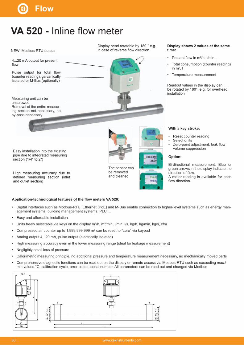
Application-technological features of the flow meters VA 520:
• Digital interfaces such as Modbus-RTU, Ethernet (PoE) and M-Bus enable connection to higher-level systems such as energy man-agement systems, building management systems, PLC,...
•
• Units freely selectable via keys on the display m³/h, m³/min, l/min, l/s, kg/h, kg/min, kg/s, cfm
• Compressed air counter up to 1,999,999,999 m³ can be reset to “zero” via keypad
• Analog output 4...20 mA, pulse output (electrically isolated)
• High measuring accuracy even in the lower measuring range (ideal for leakage measurement)
• Negligibly small loss of pressure
• Calorimetric measuring principle, no additional pressure and temperature measurement necessary, no mechanically moved parts
• Comprehensive diagnostic functions can be read out on the display or remote access via Modbus-RTU such as exceeding max./min values °C, calibration cycle, error codes, serial number. All parameters can be read out and changed via Modbus
VA 520 -
4...20 mA output for present flow
Pulse output for total flow (counter reading), galvanically isolated or M-Bus (optionally)
Easy installation into the existing pipe due to integrated measuring section (1/4" to 2")
High measuring accuracy due to defined measuring section (inlet and outlet section)
Measuring unit can be unscrewed:Removal of the entire measur-ing section not necessary, no by-pass necessary
Display head rotatable by 180 ° e.g. in case of reverse flow directionNEW: Modbus-RTU output
Display shows 2 values at the same time:
•
• Total consumption (counter reading) in m³, l
• Temperature measurement
Readout values in the display can be rotated by 180°, e.g. for overhead installation
With a key stroke:
• Reset counter reading• Select units•
volume suppression
Option:
Bi-directional measurement. Blue or green arrows in the display indicate the direction of flow.A meter reading is available for each flow direction.
The sensor can be removed and cleaned
Flow
80 www.cs-instruments.com

DESCRIPTION ORDER NO. Stainless steel 1.4571
ORDER NO. Stainless steel 1.4301
0695 1520 0695 05200695 1521 0695 05210695 1522 0695 0522
0695 1523 0695 05230695 1526 0695 05260695 1524 0695 05240695 1525 0695 0525
Bi-directional measurement - includes 2x4…20 mA analogue outputs and 2x pulse outputs. These do not apply to Ethernet (PoE) and M-Bus
Z695 6000
High-pressure version PN 40 Z695 0411NPT thread (instead of R thread) - can only be ordered for stainless steel 1.4571
Z695 5015
Measuring ranges:Low-Speed (50 m/s) Z695 0520Standard (92.7 m/s) Z695 0521High-Speed (224 m/s) Z695 0522
Options:
Special measuring range for VA 520 on customer request Z695 40061% accuracy of m.v. ± 0.3 % of f.s. Z695 5005Ethernet interface for VA 500/520 and FA 500 Z695 5006Ethernet interface PoE for VA 500/520 and FA 500 Z695 5007M-Bus board for VA 500/520 and FA 500 Z695 5004
sensors3200 0001
Gas type:___ (specify gas type when placing order) Z695 5009
Gas mixture:___ (specify gas mixture when placing order) Z695 5010Real gas adjustment 3200 0015
Special cleaning oil and grease free (e.g. for oxygen applications)
0699 4005
LABS and silicone-free version including cleaning oil and grease-free
0699 4007
Additional calibration curve stored in the sensor (can be selected via display)
Z695 5011
Z695 5012
TECHNICAL DATA VA 520Parameters: m³/h, l/min (1000 mbar,
20 °C) in case of com-pressed air or Nm³/h, Nl/min (1013 mbar, 0 °C) in case of gases
Units adjustable via keys at display:
m³/h, m³/min, l/min, l/s, ft/min, cfm, m/s, kg/h, kg/min, g/s, lb/min, lb/h
Sensor: Thermal
Measured medium: Air, gases
Gas types are adjust-able over CS service software or CS data logger:
Air, nitrogen, argon, CO2, oxygen
Measuring range: See table above
Accuracy: (o. M. V. = of measured
± 1.5% of m.v. ± 0.3 % of f.s.on request:± 1% of m.v. ± 0.3% of f.s.
Operating tempera-ture:
-30…80 °C
Operating pressure: -1 to 16 bar optionally up to PN 40
Digital output: RS 485 interface, (Modbus-RTU), optional: Ethernet interface PoE), M-Bus
Analogue output: 4…20 mA for m³/h or l/min
Pulse output: 1 pulse per m³ or per litre electrically isolated. Pulse weight can be set on the display.Alternatively, the pulse output can be used as an alarm relay
Supply: 18…36 VDC, 5 W
Burden:Housing: Polycarbonate (IP 65)
Measuring section: Stainless steel, 1.4301 or 1.4571
Connection thread of measuring sections
R 1/4” to R 2" (BSP British Standard Piping) or 1/2" to 2" NPT thread
Mounting position: anyFor further accessories refer to pages 88 to 92
Measuring range for other gases see pages 96 to 99Connection thread Outer
pipeInner pipe
Measuring range full scales
L L1 H H1 A
mm mm m³/h cfm mm mm mm mm mm13.7 8.9 105 l/min 3.6 194 137 174.7 165.7 1521.3 16.1 90 50 300 210 176.4 165.7 2026.9 21.7 175 100 475 275 179.2 165.7 2033.7 27.3 290 170 475 275 182.6 165.7 2542.4 36.0 530 310 475 275 186.9 165.7 2548.3 41.9 730 430 475* 275 186.9 165.7 2560.3 53.1 1195 700 475* 275 195.9 165.7 30
*Attention: Shortened inlet section. Please observe the recommended minimum inlet section (length = 15 x inner diameter) on site!
Flow
81www.cs-instruments.com

VA 521 - and other types of gas
The newly developed VA 521 combines modern digital interfaces for connection to energy monitoring systems with a small, compact design. The VA 521 is always used when many machines (compressed air consumers) are to be integrated into an energy monitoring network.
Readout values in the display can be rotated by 180°, e.g. for overhead installa-tion
Display shows 2 values at the same time:
•
• Total consumption (counter reading) in m³, l, kg
• Temperature measurement
Screw-in thread:Easy installation into the existing pipe due to integrated measuring section (suitable for 1/2", 3/4", 1", 1 1/4", 1 1/2" or 2" lines)
Advantages at a glance:
• Compact, small design - for use in ma-chines, behind maintenance unit on the end user
• All interfaces are freely programmable via the display
• Modbus-RTU output
• 4...20 mA analogue output for present
• electrically isolated. Optional: M-Bus, Ethernet interface or PoE
With a key stroke:
• Reset counter reading
• Select units
• Parameterise interfaces
Integrated flow straightener - no inlet section necessary
Measuring ranges for other types of gas see pages 100 to 103
Measuring section
Thread Measuring range full scales
L B H1 H A1 A
m³/h cfm mm mm mm mm mm mm
DN 15 90 m³/h 50 135 55 50 109.65 25 20
DN 20 170 m³/h 100 135 55 50 109.65 26 20
DN 25 290 m³/h 170 135 55 50 109.65 33 25
DN 32 530 m³/h 310 135 80 80 215.45 35 25
DN 40 730 m³/h 430 135 80 80 215.45 36 25
DN 50 1195 m³/h 700 135 80 80 215.45 44 30
The sensor can be removed from the measuring section and cleaned.
Flow
82 www.cs-instruments.com

Example order code VA 521:0696 0521_A1_B1_C1_D1_E1_F1_G1_H1_I1_J1_K1_L1_M1_R1
Measuring sectionA2A3A4A5A6A7
Threaded versionB1 G female threadB2 NPT female thread
Material typeC1 AluminiumC2 Stainless steel 316L
Adjustment/calibration
D1 constantD2 Real gas adjustment in the gas type selected below
Gas typeE1 Compressed airE2 Nitrogen (N2)E3 Argon (Ar)E4 Carbon dioxide (CO2)E5 Oxygen (O2)E6 Nitrous oxide (N2O)E90 Further gas / please indicate gas type (on request)E91 Gas mixture / please indicate mixture ratio (on request)
F1 Low-speed version (50 m/s)F2 Standard version (92,7 m/s)F3 Max version (185 m/s)F4 High-speed version (224 m/s)
Reference standardG1 20 °C, 1000 mbarG2 0 °C, 1013.25 mbarG3 15 °C, 981 mbarG4 15 °C, 1013.25 mbar
Display optionH1 with integrated displayH2 without display
Pressure measurement optionI1 without pressure sensor
Signal / bus connection optionJ1 1 x 4…20 mA analogue output (not electrically isolated),
pulse output, RS 485 (Modbus-RTU)
J2Ethernet interface (Modbus / TCP), 1 x 4…20 mA ana-logue output (not electrically isolated, RS), 485 (Mod-bus-RTU)
J3Ethernet interface PoE (Modbus / TCP), 1 x 4…20 mA analogue output (not electrically isolated), RS 485 (Mod-bus-RTU)
J4 M-Bus, 1 x 4…20 mA analogue output (not electrically isolated), RS 485 (Modbus-RTU)
Flow straightener
K1 -tion necessary (with measuring section 1/2" to 2")
Accuracy classL1 ± 1.5% of m.v. ± 0.3% of f.s. L2 ± 1% of m.v. ± 0.3% of f.s.
Maximum pressureM1 16 barM2 40 bar
Surface conditonN1 standard version
N2 Special cleaning oil and grease free (e. g. for oxygen applications and so on)
N3 Silicone-free version including special cleaning oil and grease-free
Special measuring range
R1 Special measuring range (please specify when placing order)
DESCRIPTION ORDER NO.0696 0521 + Order code A_…R_
Order no. VA 521
TECHNICAL DATA VA 521Parameters: m³/h, l/min (1000 mbar, 20 °C) in case
of compressed air or Nm³/h, Nl/min (1013 mbar, 0 °C) in case of gases
Units adjustable via keys at display:
m³/h, m³/min, l/min, l/s, ft/min, cfm, m/s, kg/h, kg/min, g/s, lb/min, lb/h
Sensor:Measured medium: Air, gases
Gas types are adjust-able over CS service software or CS data logger:
Air, nitrogen, argon, CO2, oxygen
Measuring range: See table
Accuracy:(o. M. V. = of measured
± 1.5% of m.v. ± 0.3 % of f.s.on request:± 1% of m.v. ± 0.3% of f.s.
Operating temperature: -30…80 °C
Operating pressure: Up to 16 bar, optionally 40 bar
Digital output: RS 485 interface, (Modbus-RTU), optional M-Bus, Ethernet interface or PoE
Analogue output: 4…20 mA for m³/h or l/min
Pulse output: 1 pulse per m³ or per litre electrically isolated. Pulse weight can be set on the display.Alternatively, the pulse output can be used as an alarm relay.
Supply: 18…36 VDC, 5 W
Burden:Housing: Polycarbonate (IP 65)
Measuring section: Aluminium, 316L
Connection thread of measuring sections:
G 1/2" to G 2" (BSP British Standard Piping) or 1/2" to 2" NPT thread
Mounting position: any
For further accessories refer to pages 88 to 92
Flow
83www.cs-instruments.com

VA 525 -
The newly developed VA 525 combines modern digital interfaces for connection to an energy monitoring system with a small, compact design. The VA 525 is always used when many machines (compressed air consumers) are to be integrated into an energy monitoring network.
Readout values in the display can be rotated by 180°, e.g. for overhead instal-lation
Display shows 2 values at the same time:
•
• Total consumption (counter reading) in m³, l, kg
• Temperature measurement
• Optional: Pressure measurement
Screw-in thread:Easy installation into the existing pipe due to integrated measuring section (suitable for 1/4", 1/2", 3/4”, 1", 1 1/4", 1 1/2" or 2" lines)
Advantages at a glance:
• Compact, small design - for use in ma-chines, behind maintenance unit on the end user
• Optionally with conventional analogueue signals (4…20 mA and pulse) or digital interfaces such as Modbus-RTU, Ethernet (also PoE), M-Bus
• All interfaces are freely programmable via the display
With a key stroke:
• Reset counter reading
• Select units
• Parameterise interfaces
Integrated flow straightener - no inlet section necessary
Measuring ranges for other types of gas see pages 100 to 103
Measuring section
Thread Measuring range full scales
L B H1 H A
m³/h cfm mm mm mm mm mm
DN 8 105 l/min 3.6 135 55 50 109.1 15
DN 15 90 m³/h 50 135 55 50 109.1 20
DN 20 170 m³/h 100 135 55 50 109.1 20
DN 25 290 m³/h 170 135 55 50 109.1 25
DN 32 530 m³/h 310 135 80 80 139.1 25
DN 40 730 m³/h 430 135 80 80 139.1 25
DN 50 1195 m³/h 700 135 80 80 139.1 30
Flow
84 www.cs-instruments.com

Example order code VA 525:0695 5250_A1_B1_C1_D1_E1_F1_G1_H1_I1_J1_K1_L1_M1_R1
Measuring sectionA1A2A3A4A5A6A7
Threaded versionB1 G female threadB2 NPT female thread
Material type
C1 Aluminium
Adjustment/calibration
D1 constantD2 Real gas adjustment in the gas type selected below
Gas typeE1 Compressed airE2 Nitrogen (N2)
F1 Low-speed version (50 m/s)F2 Standard version (92,7 m/s)F3 Max version (185 m/s)F4 High-speed version (224 m/s)
Reference standardG1 20 °C, 1000 mbarG2 0 °C, 1013.25 mbarG3 15 °C, 981 mbarG4 15 °C, 1013.25 mbar
Display optionH1 with integrated displayH2 without display
Pressure measurement optionI1 without pressure sensor
I2 With integrated pressure sensor 0…16 bar (output only via digital interfaces)
I3with integrated pressure sensor 10…2000 mbar (abs), for vacuum applications (output only via digital interfac-es)
Signal output / bus connection option
J1 outputJ2 Modbus-RTU (RS485)J3 Ethernet interface (Modbus/TCP)J4 Ethernet interface Power over Ethernet (Modbus/TCP)J5 M-Bus
K1 -tion necessary (with measuring section 1/2" to 2")
K2
Maximum pressureM1 16 bar
Surface conditonN1 standard version
Accuracy classL1 ± 1.5% of m.v. ± 0.3% of f.s.L2 ± 6% of m.v. ± 0.5% of f.s. L3 ± 1% of m.v. ± 0.3% of f.s.
Special measuring range
R1 Special measuring range (please specify when placing order)
DESCRIPTION ORDER NO.0695 5250 + Order code A_…R_
Order no. VA 525
TECHNICAL DATA VA 525Parameters: m³/h, l/min (1000 mbar, 20 °C) in case
of compressed air or Nm³/h, Nl/min (1013 mbar, 0 °C) in case of gases
Units adjustable via keys at display:
m³/h, m³/min, l/min, l/s, ft/min, cfm, m/s, kg/h, kg/min, g/s, lb/min, lb/h
Sensor:Measured medium: Air, gases
Gas types are adjust-able over CS service software or CS data logger:
Air, nitrogen, argon, CO2
Measuring range: See table above
Accuracy:(o. M. V. = of measured
± 1.5% of m.v. ± 0.3 % of f.s. on request:± 1% of m.v. ± 0.3% of f.s. or ± 6% of m.v. ± 0.5% of f.s.
Pressure measure-ment:
0…16 bar, accuracy: 1%, or10…2000 mbar (abs)
Operating tempera-ture:
-20…60 °C
Operating pressure: Up to 16 bar
Digital output: RS 485 interface, (Modbus-RTU), M-Bus (optional) Ethernet interface or PoE
Analogue output: 4…20 mA for m³/h or l/min
Pulse output: 1 pulse per m³ or per litre electrically isolated. Pulse weight can be set on the display.Alternatively, the pulse output can be used as an alarm relay.
Supply: 18…36 VDC, 5 W
Burden:Housing: Polycarbonate (IP 65)
Measuring section: Aluminium
Connection thread of measuring sections:
G 1/4" to G 2" (BSP British Standard Piping) or 1/2" to 2" NPT thread
Mounting position: any
Flow
85www.cs-instruments.com

VD 500 -
Benefits at a glance:
• • Extremely fast response time: 100 ms• Flow, total consumption, temperature and pressure• Measurement at high temperatures, max. temperature 180 °C• Measurement in various gases by selecting the gas type, on request• Can be used in pipes from DN 20 to DN 500• • RS 485 interface (Modbus-RTU), 4...20 mA, pulse output as standard
TECHNICAL DATA VD 500Measuring range: up to 224 m/s / 600 m/s
Measured medium: Air, non-aggressive gasesAccuracy: ± 1.5% of m.v. ± 0.3% of f.s.(20...224 m/s)
± 1.5% of m.v. (> 224 m/s)
Measuring principle:Measuring span: 1:10Response time: t 99: < 1 sec.Temperature of the medium: -30 °…+180 °COperating pressure: Max. 20 barAmbient temperature: -30 °…+70 °CScrew-in thread:Power supply: 18…36 VDC, 5 W
Signal outputs: As standard:RS 485 (Modbus-RTU), 4…20 mA, pulseOptional:Ethernet Interface (PoE), M-Bus
For measuring immediately downstream of the compressor in moist air up to +180 °C
Typical applications:
• Measurement of the capacity of compressors• Compressed air audits•
Installation requirements:
• After functioning water separator• In horizontal lines (recommended) or in risers
The integrated, precise differential pressure sensor measures the differential pressure/dynamic pressure at the sensor tip. The pres-sure depends on the respective gas velocity. The flow is therefore easy to determine by means of the pipe diameter.The additional measurement of temperature and absolute pressure and calculation of the relevant density means that measuring can be carried out for various gases, a wide variety of temperatures and pressures.
FIELD OF APPLICATION:
• Measurement immediately downstream of the compressor
• Measurement at high temperatures
• Measurement of fast processes
Flow
86 www.cs-instruments.com

Simple installation and removal under pres-sure
Installation depth = x + ydA = outer diameterx = dA 2 180
170
160
Engraved depth scale for pre-cise installation
Measuring rangeA1 224 m/sA2 600 m/s
Screw-in threadB1B2
Installation length / shaft lengthC1 220 mmC2 400 mm
DisplayD1 with integrated display
Signal outputs / bus connection option
E1 1x 4…20 mA analogue output (electrically not isolated),pulse output, RS 485 (Modbus-RTU)
E2Ethernet interface (Modbus/TCP), 1 x 4…20 mA analogue output (not electrically isolated), RS 485 (Modbus-RTU)
E3Ethernet interface PoE (Power over Ethernet) (Modbus/TCP), 1 x 4…20 mA analogue output (not electrically isolated), RS 485 (Modbus-RTU)
E4 M-Bus, 1 x 4…20 mA analogue output (not electrically isolated), RS 485 (Modbus-RTU)
Reference standardG1 20 °C, 1000 mbarG2 0 °C, 1013.25 mbar G3 15 °C, 981 mbarG4 15 °C, 1013.25 mbar
Gas typeK1 Compressed airK90 Additional gas on request
Example order code VD 500:0690 5001_A1_B1_C1_D1_E1_F1_G1_K1
Inside diameter of pipe VD 50020 … 224 m/s
Measuring range initial values and full scaleInch mm DN m³/h (cfm)
21.7 DN 20 19 … 215 11 … 127
27.3 DN 25 32 … 357 19 … 210
36.0 DN 32 57 … 644 34 … 379
41.9 DN 40 79 … 886 47 … 522
53.1 DN 50 130 … 1450 76 … 853
68.9 DN 65 222 … 2484 131 … 1462
80.9 DN 80 307 … 3440 181 … 2025
110.0 DN 100 571 … 6391 336 … 3762
133.7 DN 125 844 … 9453 497 … 5564
159.3 DN 150 1200 … 13436 706 … 7908
200.0 DN 200 1896 … 21230 1116 … 12495
250.0 DN 250 2966 … 33211 1746 … 19547
300.0 DN 300 4276 … 47881 2517 … 28182
160
dA
DESCRIPTION ORDER NO.0690 5001 + Order code A_...K_
Accessories:
3200 0001
High-pressure protection 0530 1117
)15°
For further accessories refer to pages 88 to 92
y
x
Recommended installation position
Flow
87www.cs-instruments.com

Accessories VA 500/520/525
DESCRIPTION ORDER NO.Connection cable for VA/FA series, 5 m 0553 0104Connection cable for VA/FA sensors, 10 m 0553 0105Connection cable for VA/FA series, 20 m 0553 0120Cable for alarm/pulse output, with M12 plug, 5 m 0553 0106Cable for alarm/pulse output, with M12 plug, 10 m 0553 0107Connection cable for VA/FA series, 5 m shielded 0553 0129Connection cable for VA/FA series, 10 m shielded 0553 0130
DESCRIPTION ORDER NO.Ethernet connection cable, length 5 m, M12 plug x-coded (8 pin) to RJ 45 plug
0553 2503
Ethernet connection cable, length 10 m, M12 plug x-coded (8 pin) to RJ 45 plug
0553 2504
DESCRIPTION ORDER NO.M12 plug for VA 500/520/525 0 2000 0082M12 plug 90° angled 0219 0060
DESCRIPTION ORDER NO.M12 T-plug for VA 500/520 for connecting multiple sensors to an M-Bus or Modbus network
0 2000 0823
DESCRIPTION ORDER NO.Drilling jig incl. drill (Ø 13 mm) 0530 1108
Accessories VA 500/550
Flow
88 www.cs-instruments.com

DESCRIPTION ORDER NO.High-pressure protection recommended for installation from 10 to 50 bar (for VA 400/500)
0530 1105
DESCRIPTION ORDER NO.
High-pressure protection recommended for installation from 10 to 100 bar (for VA 550)
0530 1115
High-pressure protection recommended for installation from 10 to 16 bar DVGW (for VA 550)
0530 1116
DESCRIPTION ORDER NO.Welding nipple, L = 35 mm, male thread, R 1/2" stainless steel 1.4301 3300 0006Welding nipple, L = 35 mm, male thread, R 1/2" stainless steel 1.4571 3300 0007
DESCRIPTION ORDER NO.Wall thickness measuring device CS 0495 incl. case and calibration block
0560 0495
DESCRIPTION ORDER NO.Ball valve I/I G 1/2" stainless steel 3300 0002
• Only suitable for VA 500 with sensor length: 160 mm, 220 mm, 300 mm. Fur-ther sensor lengths on request
Flow
89www.cs-instruments.com

Accessories VA 500/550
DESCRIPTION ORDER NO.X-connection for connection of pressure and dew point sensor at the same measuring point (incl. 2x quick-lock coupling)
0553 0133
DESCRIPTION ORDER NO.
0553 0134
DESCRIPTION ORDER NO.PNG cable screwing - for standard 0553 0552PNG cable screwing - for ATEX 0553 0551
DESCRIPTION ORDER NO.Connection cable 5 m with open ends 0553 0108Connection cable 10 m with open ends 0553 0109
DESCRIPTION ORDER NO.Closing cap for measuring section VA 520/VA 570 (material: alumini-um)
0190 0001
Closing cap for measuring section VA 520/VA 570 (material: stainless steel 1.4571)
0190 0002
Accessories VA 550/570
Accessories VA 520/570
Standard ATEX
Aluminium
Flow
90 www.cs-instruments.com

Accessories for all VA 5xx
DESCRIPTION ORDER NO.Mains unit in wall housing for maximum 2 sensors of the series VA/FA 5xx, 100-240 V, 23 VA, 50-60 Hz / 24 VDC, 0.35 A
0554 0110
Mains unit in wall housing for max. 4 sensors of the series VA500/520100-240 V, 23 VA, 50-60 Hz / 24 VDC, 0,35 A
0554 0111
DESCRIPTION ORDER NO.
AC adapter plug 100-240 V, AC/24 V for VA/FA 5xx 0554 0109
DESCRIPTION ORDER NO.External Gateway PROFIBUS for connection to integrated RS 485 interface
Z500 3008
External Gateway PROFINET for connection to integrated RS 485 interface
Z500 3009
DESCRIPTION ORDER NO.CS Service Software incl. PC connection set, USB connection and interface adapter to the sensor
0554 2007
DESCRIPTION ORDER NO.Case for all sensors (dimensions: 500 x 360 x 120 mm) 0554 6006
USB
Power supply
AdapterVA 550/570
Flow
91www.cs-instruments.com

Measuring sections for precise measurements:Measuring section in stainless steel 1.4301 incl. ball valve, up to DN 65 (R2 1/2") with R-male thread, from DN 80 with weld neck flange in acc. with DIN 2633.
MALE THREAD PIPE (OUTERØ X WALL TOTAL LENGTH ORDER NO.
21.3 x 2.6 mm 500 mm 4000 0015
26.9 x 2.6 mm 600 mm 4000 0020
33.7 x 3.2 mm 750 mm 4000 0025
42.4 x 3.2 mm 900 mm 4000 0032
48.3 x 3.2 mm 1000 mm 4000 0040
60.3 x 3.6 mm 1250 mm 4000 0050
76.1 x 3.6 mm 1500 mm 4000 0065
DN 80/88.9 88.9 x 2.0 mm 1850 mm 4000 0080
DN 100/114.3 114.3 x 2.0 mm 2104 mm 4000 0100
DN 125/139.7 139.7 x 3.0 mm 2860 mm 4000 0125
DN 150/168.3 168.3 x 3.0 mm 3110 mm 4000 0150
Practical measuring section accessories
Measuring section 1/2"
DESCRIPTION DN ORDER NO.Spot drilling collar for pipe Ø 032 - 036 mm, length: 100 mm* 0500 0446
Spot drilling collar for pipe Ø 036 - 040 mm, length: 100 mm* 0500 0448
Spot drilling collar for pipe Ø 040 - 044 mm, length: 150 mm* 0500 0449
Spot drilling collar for pipe Ø 044 - 051 mm, length: 200 mm* 0500 0610
Spot drilling collar for pipe Ø 048 - 055 mm, length: 200 mm* 40 0500 0611
Spot drilling collar for pipe Ø 052 - 059 mm, length: 200 mm* 0500 0612
Spot drilling collar for pipe Ø 057 - 064 mm, length: 200 mm* 50 0500 0613
Spot drilling collar for pipe Ø 063 - 070 mm, length: 200 mm* 0500 0614
Spot drilling collar for pipe Ø 070 - 077 mm, length: 200 mm* 65 0500 0615
Spot drilling collar for pipe Ø 075 - 083 mm, length: 200 mm* 0500 0616
Spot drilling collar for pipe Ø 082 - 090 mm, length: 200 mm* 0500 0617
Spot drilling collar for pipe Ø 087 - 097 mm, length: 200 mm* 80 0500 0618
Spot drilling collar for pipe Ø 095 - 104 mm, length: 200 mm* 0500 0619
Spot drilling collar for pipe Ø 102 - 112 mm, length: 200 mm* 0500 0620
Spot drilling collar for pipe Ø 108 - 118 mm, length: 200 mm* 100 0500 0621
Spot drilling collar for pipe Ø 118 - 128 mm, length: 200 mm* 0500 0622
Spot drilling collar for pipe Ø 125 - 135 mm, length: 200 mm* 0500 0623
Spot drilling collar for pipe Ø 133 - 144 mm, length: 200 mm* 125 0500 0624
Spot drilling collar for pipe Ø 145 - 155 mm, length: 250 mm* 0500 0625
Spot drilling collar for pipe Ø 151 - 161 mm, length: 250 mm* 150 0500 0626
Spot drilling collar for pipe Ø 159 - 170 mm, length: 250 mm* 0500 0627
Spot drilling collar for pipe Ø 168 - 180 mm, length: 250 mm* 0500 0628
Spot drilling collar for pipe Ø 180 - 191 mm, length: 250 mm* 175 0500 0629
Spot drilling collar for pipe Ø 193 - 203 mm, length: 300 mm* 0500 0630
Spot drilling collar for pipe Ø 200 - 210 mm, length: 300 mm* 0500 0631
Spot drilling collar for pipe Ø 209 - 220 mm, length: 300 mm* 200 0500 0632
If there is no measuring site with 1/2" ball valve present on existing pipes, it can be set up quickly and cost-effectively by means of spot drilling collars. The spot drilling collar is imposed onto the pipe and tightened via thread rods. The enveloping rubber gasket is pressure-tight up to 10 bar. By means of the drilling jig, it is possible to drill the spot drilling collar through the 1/2" ball valve into the existing pipe.
Important: Please indicate the exact outer diameter of the existing pipe when placing the order resp. please select the suitable spot drilling collar from the adjoining list.
*incl. 1/2" ball valve* not suitable for copper and plastic pipes
Practical spot drilling collar accessories for compressed air lines
Flow
92 www.cs-instruments.com

VA 409 - Flow direction switch for compressed air systems
DESCRIPTION ORDER NO.Direction switch VA 409 0695 0409
Mains unit in wall housing for maximum 2 sensors of the series VA/FA 5xx,100-240 V, 23 VA, 50-60 Hz / 24 VDC, 0,35 A
0554 0110
Connection cable for VA/FA series, 5 m 0553 0104
Connection cable for VA/FA sensors, 10 m 0553 0105
The thermal flow direction switch VA 409 with direction indication serves for determination of the flow direction of compressed air and gases especially in closed circular pipelines.
By means of VA 409 with flow direction indication the flow direction of the compressed air can be determined quickly and safely. Compared with the former mechanical paddle flow switches VA 409 is able to detect even the smallest changes in the flow direction quickly and without any mechanical movement.
The direction information in form of a potential-free contact (normally closed max. 60 VDC, 0.5 A) is transferred to the flow meters VA 5xx or to a separate building management system (BMS). Two LEDs show the flow direction.
In connection with 2 flow sensors VA 5xx incoming and out flowing compressed air in closed circu-lar pipelines can be measured precisely.
Special features:
• detects the smallest changes < 0.1 m/s relative to 20 °C and 1,000 mbar
• no mechanical wear parts
• easy installation under pressure
TECHNICAL DATA VA 409Response area detec-tion of direction:
< 0.1 m/s relative to 20 °C and 1000 mbar
Measuring principle: Calorimetricmeasurement
Sensor: Pt 30/ Pt 700/ Pt 330
Measured medium: Air, gases
Operating tempera-ture:
0…50 °C sensor tube-20…70 °C housing
Operating pressure: up to 16 bar
Power supply: 24 VDC, 40 mA
Current consumption: Max. 80 mA to 24 VDC
Protection class: IP 54
EMC: in acc. with DIN EN 61326
Connection: 2 x M12, 5-pin, plug A and plug B
2 potential-free con-tacts:
2 x U max. 60 VDC, l max 0.5 A (normally closed); on request: Normally open
Housing: Polycarbonate
Sensor tube: Stainless steel, 1.4301, length 160 mm, Ø 10 mm, safety ring Ø 11.5 mm, longer sensors on request
Mounting thread:Housing diameter: 65 mm
Direction indication: 2 LEDs
Flow
93www.cs-instruments.com

CS Service Software - … incl. PC connection set, USB connection and interface adapter to the sensor.
DESCRIPTION ORDER NO.CS Service Software for FA/VA sensors incl. PC connection set, USB connection and interface adapter to the sensor
0554 2007
The flow meters VA 5xx can be connected to the PC, and the following settings can be made by means of the CS Service Software:
• Selection of gas type (air, CO2, N2O, N2, O2, NG, Ar, CH4)
•
• Selection of units: m³/h, Nm³/h, m³/min, Nm³/min, ltr/h, Nltr/h, ltr/min, Nltr/min, ltr/s, Nltr/s, cfm, SCFM, kg/h, kg/min, kg/s
• Setting of the reference temperature, reference pressure
•
• Modbus and M-Bus settings
• Scaling of the 4...20 mA analogue output
• Reading of: Version number, production date, series no., time of last calibration
• Setting of alarm limits
•
• Reset factory settings
•
Flow
94 www.cs-instruments.com

Calibration range: from 0 to 4.000 m³/h under pressure
Accuracy of the refer-ence:
between 0.5 and 1% of the measured value
Calibration of flow meters
In the CS calibration laboratory for flow meters it is possible to calibrate our flow measuring instruments as well as of other manufacturers
High precision reference measuring devices guarantee an accuracy of up 0.5% of the measured value.
Special features:
• Due to the digital data transmission, only the -
vices remain wired on site.
DESCRIPTION ORDER NO.0695 3333
0695 3332
on requestReal gas adjustment 3200 0015
Flow
95www.cs-instruments.com
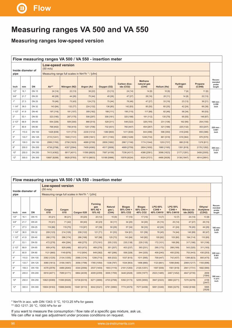
Flow measuring ranges VA 500 / VA 550 - insertion meter
Inside diameter of pipe
Low-speed version(50 m/s)
Recom-mended probe length
Measuring range full scales in Nm³/h * / [cfm]
Inch mm DN Air**Carbon diox-
Methane natural gas Hydrogen Propane
16.1 DN 15 24 [14] 22 [13] 38 [22] 23 [13] 24 [14] 14 [8] 10 [6] 7 [4] 11 [6]
160 mm - 6.299 inch
21.7 DN 20 48 [28] 44 [26] 75 [44] 45 [26] 47 [27] 28 [16] 20 [11] 14 [8] 22 [13]
27.3 DN 25 79 [46] 73 [43] 124 [73] 75 [44] 78 [46] 47 [27] 33 [19] 23 [13] 36 [21]
36.0 DN 32 143 [84] 132 [77] 224 [132] 136 [80] 142 [83] 85 [50] 60 [35] 42 [24] 66 [38]
41.9 DN 40 197 [116] 181 [107] 309 [182] 188 [111] 195 [115] 117 [68] 82 [48] 58 [34] 90 [53]
53.1 DN 50 323 [190] 297 [175] 506 [297] 308 [181] 320 [188] 191 [112] 135 [79] 95 [55] 148 [87]
68.9 DN 65 554 [326] 509 [300] 866 [510] 528 [311] 548 [322] 328 [193] 231 [136] 162 [95] 254 [150]
220 mm - 8.661 inch
80.9 DN 80 768 [452] 706 [415] 1201 [706] 732 [431] 760 [447] 454 [267] 321 [188] 225 [132] 353 [207]
110.0 DN 100 1426 [839] 1311 [772] 2230 [1312] 1360 [800] 1411 [830] 844 [496] 596 [350] 418 [246] 655 [386]
133.7 DN 125 2110 [1241] 1940 [1141] 3299 [1941] 2011 [1183] 2088 [1228] 1248 [734] 881 [519] 619 [364] 970 [570]
159.3 DN 150 2999 [1765] 2758 [1623] 4689 [2759] 2859 [1682] 2967 [1746] 1774 [1044] 1253 [737] 880 [518] 1379 [811]
300 mm - 11.811 inch
200.0 DN 200 4738 [2788] 4357 [2564] 7409 [4360] 4517 [2658] 4689 [2759] 2804 [1650] 1980 [1165] 1391 [819] 2178 [1282]
250.0 DN 250 7413 [4362] 6817 [4011] 11590 [6820] 7067 [4159] 7336 [4317] 4386 [2581] 3098 [1823] 2177 [1281] 3408 [2005]
300.0 DN 300 10687 [6289] 9828 [5783] 16710 [9833] 10189 [5996] 10576 [6224] 6324 [3721] 4466 [2628] 3138 [1847] 4914 [2891]
Flow measuring ranges VA 500 / VA 550 - insertion meter
Inside diameter of pipe
Low-speed version(50 m/s)
Recom-mended probe length
Measuring range full scales in Nm³/h * / [cfm]
Inch mm DNCorgon
®18Corgon
®10 Corgon ®20
Forming gas
10% H2
Natural gas L
Biogas
50% CO2
Biogas
40% CO2
LPG 60%
40% C4H10
LPG 50%
50% C4H10Nitrous ox-
Ethyne/Acetylene
16.1 DN 15 35 [21] 36 [21] 35 [20] 20 [12] 15 [9] 17 [10] 17 [10] 13 [7] 12 [7] 24 [14] 13 [8]
160 mm- 6.299 inch
21.7 DN 20 70 [41] 71 [42] 69 [40] 40 [23] 30 [17] 34 [20] 34 [20] 25 [15] 25 [14] 47 [27] 26 [15]
27.3 DN 25 116 [68] 119 [70] 115 [67] 67 [39] 50 [29] 57 [34] 56 [33] 42 [24] 41 [24] 78 [45] 44 [26]
36.0 DN 32 209 [123] 214 [126] 208 [122] 121 [71] 91 [53] 104 [61] 101 [59] 76 [45] 74 [44] 140 [89] 80 [47]
41.9 DN 40 288 [170] 296 [174] 286 [168] 167 [98] 125 [73] 143 [84] 140 [82] 105 [62] 103 [60] 194 [114] 110 [65]
53.1 DN 50 472 [278] 484 [284] 468 [275] 273 [161] 205 [120] 235 [138] 229 [135] 172 [101] 168 [99] 317 [186] 181 [106]
68.9 DN 65 809 [476] 829 [488] 803 [472] 469 [276] 351 [207] 403 [237] 393 [231] 295 [173] 288 [169] 543 [320] 311 [183]
220 mm - 8.661 inch
80.9 DN 80 1121 [660] 1149 [676] 1112 [654] 649 [382] 487 [286] 558 [328] 544 [320] 409 [240] 400 [235] 753 [443] 430 [253]
110.0 DN 100 2082 [1225] 2134 [1255] 2066 [1216] 1206 [710] 905 [532] 1037 [610] 1011 [595] 759 [447] 742 [437] 1399 [823] 800 [470]
133.7 DN 125 3080 [1813] 3156 [1857] 3056 [1798] 1785 [1050] 1338 [787] 1534 [903] 1496 [880] 1123 [661] 1098 [646] 2069 [1217] 1183 [696]
159.3 DN 150 4378 [2576] 4486 [2640] 4344 [2556] 2537 [1493] 1903 [1119] 2181 [1283] 2126 [1251] 1597 [939] 1561 [919] 2941 [1731] 1682 [990]
300 mm - 11.811inch
200.0 DN 200 6918 [4071] 7089 [4171] 6864 [4039] 4009 [2359] 3006 [1769] 3446 [2028] 3359 [1977] 2523 [1485] 2467 [1452] 4647 [2735] 2658 [1564]
250.0 DN 250 10823 [6369] 11090 [6526] 10738 [6319] 6271 [3690] 4703 [2768] 5392 [3173] 5255 [3093] 3947 [2323] 3860 [2271] 7270 [4278] 4158 [2447]
300.0 DN 300 15604 [9183] 15988 [9409] 15481 [9110] 9042 [5321] 6781 [3990] 7774 [4575] 7577 [4459] 5691 [3349] 5565 [3275] 10482 [6168] 5995 [3528]
Measuring ranges VA 500 and VA 550Measuring ranges low-speed version
If you want to measure the consumption / flow rate of a specific gas mixture, ask us.We can offer a real gas adjustment under process conditions on request.
* Nm³/h in acc. with DIN 1343: 0 °C, 1013.25 hPa for gases** ISO 1217: 20 °C, 1000 hPa for air
Flow
96 www.cs-instruments.com

Flow measuring ranges VA 500 / VA 550 - insertion meter
Inside diameter of pipe
Standard version(92.7 m/s)
Recom-mended probe length
Measuring range Nm³/h * / [cfm]
Inch mm DN Air**Carbon diox-
MethaneNatural gas Propane
16.1 DN 15 45 [26] 41 [24] 71 [41] 43 [25] 45 [26] 26 [15] 19 [11] 13 [7] 20 [12]
160 mm - 6.299 inch
21.7 DN 20 89 [52] 81 [48] 139 [81] 84 [49] 88 [51] 52 [31] 37 [21] 26 [15] 40 [24]
27.3 DN 25 147 [86] 135 [79] 230 [135] 140 [82] 146 [86] 87 [51] 61 [36] 43 [25] 67 [39]
36.0 DN 32 266 [156] 244 [144] 416 [245] 253 [149] 263 [155] 157 [92] 111 [65] 78 [46] 122 [72]
41.9 DN 40 366 [215] 337 [198] 573 [337] 349 [205] 363 [213] 217 [127] 153 [90] 107 [63] 168 [99]
53.1 DN 50 600 [353] 551 [324] 938 [552] 572 [336] 593 [349] 355 [208] 250 [147] 176 [103] 275 [162]
68.9 DN 65 1028 [604] 945 [556] 1607 [945] 980 [576] 1017 [598] 608 [358] 429 [252] 301 [177] 472 [278]
220 mm - 8.661 inch
80.9 DN 80 1424 [838] 1309 [770] 2227 [1310] 1358 [799] 1409 [829] 842 [496] 595 [350] 418 [246] 654 [385]
110.0 DN 100 2644 [1556] 2432 [1431] 4135 [2433] 2521 [1484] 2617 [1540] 1565 [921] 1105 [650] 776 [457] 1216 [715]
133.7 DN 125 3912 [2302] 3597 [2117] 6116 [3599] 3729 [2195] 3871 [2278] 2315 [1362] 1635 [962] 1149 [676] 1798 [1058]
159.3 DN 150 5560 [3272] 5113 [3009] 8693 [5116] 5301 [3119] 5502 [3238] 3290 [1936] 2324 [1367] 1633 [961] 2556 [1504]
300 mm - 11.811 inch
200.0 DN 200 8785 [5170] 8079 [4754] 13736 [8083] 8376 [4929] 8694 [5116] 5198 [3059] 3672 [2160] 2580 [1518] 4039 [2377]
250.0 DN 250 13744 [8088] 12638 [7437] 21488 [12646] 13103 [7711] 13601 [8004] 8133 [4786] 5744 [3380] 4036 [2375] 6319 [3718]
300.0 DN 300 19814 [11661] 18221 [10723] 30980 [18232] 18891 [11117] 19609 [11539] 11725 [6900] 8281 [4873] 5819 [3424] 9110 [5361]
Flow measuring ranges VA 500 / VA 550 - insertion meter
Inside diameter of pipe
Standard version(92.7 m/s)
Recom-mended probe length
Measuring range full scales in Nm³/h * / [cfm]
Inch mm DNCorgon
®18 Corgon ®10 Corgon ®20
Forming gas 90%
H2
Natural gas L
Biogas
50% CO2
Biogas
40% CO2
LPG60% C3H8
C4H10
LPG50% C3H8
C4H10
Nitrous Oxide
Ethyne/Acety-lene
16.1 DN 15 66 [39] 68 [40] 66 [38] 38 [22] 28 [17] 33 [19] 32 [19] 24 [14] 23 [13] 44 [26] 25 [15]
160 mm - 6.299 inch
21.7 DN 20 130 [76] 133 [78] 129 [75] 75 [44] 56 [33] 64 [38] 63 [37] 47 [27] 46 [27] 87 [51] 49 [29]
27.3 DN 25 215 [126] 220 [130] 213 [125] 124 [73] 93 [55] 107 [63] 104 [61] 78 [46] 76 [45] 144 [85] 82 [48]
36.0 DN 32 388 [228] 398 [234] 385 [227] 225 [132] 168 [99] 193 [114] 188 [111] 141 [83] 138 [81] 261 [153] 149 [87]
41.9 DN 40 535 [315] 548 [322] 531 [312] 310 [182] 232 [136] 266 [157] 260 [153] 195 [114] 191 [112] 359 [211] 205 [121]
53.1 DN 50 876 [515] 897 [528] 869 [511] 507 [298] 380 [224] 436 [256] 425 [250] 319 [188] 312 [183] 588 [346] 336 [198]
68.9 DN 65 1500 [883] 1537 [905] 1489 [876] 869 [511] 652 [383] 747 [440] 728 [428] 547 [322] 535 [315] 1008 [593] 576 [339]
220 mm - 8.661 inch
80.9 DN 80 2079 [1223] 2130 [1254] 2063 [1214] 1205 [709] 903 [531] 1036 [609] 1009 [594] 758 [446] 741 [436] 1397 [822] 799 [470]
110.0 DN 100 3861 [2272] 3956 [2328] 3831 [2254] 2237 [1316] 1678 [987] 1923 [1132] 1875 [1103] 1408 [828] 1377 [810] 2594 [1526] 1483 [873]
133.7 DN 125 5711 [3361] 5852 [3444] 5666 [3335] 3309 [1947] 2482 [1460] 2845 [1674] 2773 [1632] 2083 [1226] 2037 [1198] 3837 [2258] 2194 [1291]
159.3 DN 150 8118 [4777] 8318 [4895] 8054 [4740] 4704 [2768] 3528 [2076] 4044 [2380] 3942 [2320] 2961 [1742] 2895 [1704] 5453 [3209] 3119 [1835]
300 mm - 11.811 inch
200.0 DN 200 12827 [7548] 13143 [7734] 12726 [7489] 7432 [4374] 5574 [3280] 6390 [3760] 6229 [3665] 4678 [2753] 4575 [2692] 8616 [5071] 4928 [2900]
250.0 DN 250 20066 [11809] 20560 [12100] 19908 [11716] 11627 [6842] 8720 [5132] 9997 [5883] 9744 [5734] 7319 [4307] 7157 [4212] 13480 [7932] 7709 [4537]
300.0 DN 300 28930 [17025] 29643 [17444] 28702 [16891] 16763 [9865] 12572 [7399] 14413 [8482] 14048 [8267]
10552 [6209] 10318 [6072] 19434 [11437]
11115 [6541]
Measuring ranges Standard version
If you want to measure the consumption / flow rate of a specific gas mixture, ask us.We can offer a real gas adjustment under process conditions on request.
* Nm³/h in acc. with DIN 1343: 0 °C, 1013.25 hPa for gases** ISO 1217: 20 °C, 1000 hPa for air
Flow
97www.cs-instruments.com

Flow measuring ranges VA 500 / VA 550 - insertion meter
Inside diameter of pipe
Max version(185.0 m/s)
Recom-mended probe length
Measuring range Nm³/h * / [cfm]
Inch mm DN Air**Carbon dioxide
MethaneNatural gas Hydrogen Propane
16.1 DN 15 90 [53] 83 [49] 142 [83] 86 [51] 90 [52] 53 [31] 38 [22] 26 [15] 41 [24]
160 mm - 6.299 inch
21.7 DN 20 177 [104] 163 [96] 278 [163] 169 [99] 175 [103] 105 [61] 74 [43] 52 [30] 81 [48]
27.3 DN 25 294 [173] 271 [159] 460 [271] 280 [165] 291 [171] 174 [102] 123 [72] 86 [50] 135 [79]
36.0 DN 32 531 [312] 488 [287] 830 [489] 506 [298] 525 [309] 314 [185] 222 [130] 156 [91] 244 [143]
41.9 DN 40 732 [430] 673 [396] 1144 [673] 697 [410] 724 [426] 433 [254] 305 [180] 215 [126] 336 [198]
53.1 DN 50 1197 [704] 1101 [648] 1872 [1101] 1141 [671] 1185 [697] 708 [417] 500 [294] 351 [206] 550 [324]
68.9 DN 65 2051 [1207] 1886 [1110] 3207 [1887] 1955 [1151] 2030 [1194] 1214 [714] 857 [504] 602 [354] 943 [555]
220 mm - 8.661 inch
80.9 DN 80 2842 [1672] 2614 [1538] 4444 [2615] 2710 [1594] 2813 [1655] 1682 [989] 1188 [699] 834 [491] 1307 [769]
110.0 DN 100 5278 [3106] 4854 [2856] 8252 [4856] 5032 [2961] 5223 [3074] 3123 [1838] 2206 [1298] 1550 [912] 2427 [1428]
133.7 DN 125 7807 [4594] 7179 [4225] 12206 [7183] 7443 [4380] 7726 [4546] 4620 [2718] 3263 [1920] 2293 [1349] 3589 [2112]
159.3 DN 150 11096 [6530] 10204 [6005] 17349 [10210] 10579 [6226] 10981 [6462] 6566 [3864] 4637 [2729] 3259 [1917] 5102 [3002]
300 mm - 11.811
inch
200.0 DN 200 17533 [10318] 16123 [9488] 27413 [16132] 16716 [9837] 17351 [10211] 10375 [6105] 7328 [4312] 5149 [3030] 8061 [4744]
250.0 DN 250 27428 [16141] 25223 [14843] 42884 [25237] 26150 [15389] 27143 [15974] 16231 [9552] 11463 [6746] 8055 [4740] 12611 [7421]
300.0 DN 300 39544 [23271] 36364 [21400] 61827 [36385] 37701 [22187] 39133 [23030] 23400 [13771] 16527 [9726] 11614 [6834] 18182 [10700]
Flow measuring ranges VA 500 / VA 550 - insertion meter
Inside diameter of pipe
Max version(185.0 m/s)
Recom-mended probe length
Measuring range Nm³/h * / [cfm]
Inch mm DNCorgon
®18Corgon
®10Corgon
®20
Forming gas
10% H2
Natural gas L
Biogas
50% CO2
Biogas60% CH4
CO2
LPG60% C3H8
C4H10
LPG50% C3H8
C4H10
Nitrous Oxide
Ethyne/Acetylene
16.1 DN 15 132 [78] 136 [80] 131 [77] 76 [45] 57 [33] 66 [38] 64 [37] 48 [28] 47 [27] 89 [52] 51 [30]
160 mm - 6.299 inch
21.7 DN 20 259 [152] 266 [156] 257 [151] 150 [88] 112 [66] 129 [76] 126 [74] 94 [55] 92 [54] 174 [102] 99 [58]
27.3 DN 25 430 [253] 440 [259] 426 [251] 249 [146] 187 [110] 214 [126] 208 [122] 156 [92] 153 [90] 289 [170] 165 [97]
36.0 DN 32 775 [456] 795 [467] 769 [453] 449 [264] 337 [198] 386 [227] 376 [221] 283 [166] 276 [162] 521 [306] 298 [175]
41.9 DN 40 1068 [629] 1095 [644] 1060 [624] 619 [364] 464 [273] 532 [313] 519 [305] 389 [229] 381 [224] 718 [422] 410 [241]
53.1 DN 50 1748 [1029] 1791 [1054] 1734 [1020] 1013 [596] 759 [447] 871 [512] 849 [499] 637 [375] 623 [367] 1174 [691] 671 [395]
68.9 DN 65 2995 [1762] 3069 [1806] 2971 [1748] 1735 [1021] 1301 [766] 1492 [878] 1454 [856] 1092 [642] 1068 [628] 2012 [1184] 1150 [677]
220 mm - 8.661 inch
80.9 DN 80 4150 [2442] 4252 [2502] 4117 [2423] 2404 [1415] 1803 [1061] 2067 [1216] 2015 [1186] 1513 [890] 1480 [871] 2788 [1640] 1594 [938]
110.0 DN 100 7706 [4535] 7896 [4647] 7646 [4499] 4465 [2628] 3349 [1971] 3839 [2259] 3742 [2202] 2811 [1654] 2748 [1617] 5177 [3046] 2961 [1742]
133.7 DN 125 11399 [6708] 11679 [6873] 11309 [6655] 6605 [3887] 4954 [2915] 5679 [3342] 5535 [3257] 4157 [2446] 4065 [2392] 7657 [4506] 4379 [2577]
159.3 DN 150 16201 [9534] 16600 [9769] 16074 [9459] 9388 [5524] 7041 [4143] 8071 [4750] 7867 [4630] 5909 [3477] 5778 [3400] 10883 [6405] 6224 [3663]
300 mm - 11.811 i
nch
200.0 DN 200 25599 [15065]
26229 [15436]
25397 [14946]
14833 [8729]
11125 [6547]
12753 [7505]
12431 [7315]
9337 5494]
9130 [5373]
17196 [10120]
9835 [5788]
250.0 DN 250 40046 [23567]
41033 [24148]
39731 [23382]
23205 [13656]
17404 [10242]
19951 [11741]
19447 [11444]
14606 [8596]
14283 [8406]
26901 [15831]
15386 [9054]
300.0 DN 300 57736 [33977]
59158 [34814]
57281 [33710]
33455 [19688]
25091 [14766]
28764 [16927]
28037 [16499]
21058 [12393]
20593 [12119]
38784 [22824]
22182 [13054]
Measuring ranges max version
If you want to measure the consumption / flow rate of a specific gas mixture, ask us.We can offer a real gas adjustment under process conditions on request.
* Nm³/h in acc. with DIN 1343: 0 °C, 1013.25 hPa for gases** ISO 1217: 20 °C, 1000 hPa for air
Flow
98 www.cs-instruments.com

Flow measuring ranges VA 500 / VA 550 - insertion meter
Inside diameter of pipe
High-speed version(224.0 m/s)
Recom-mended probe length
Measuring range Nm³/h * / [cfm]
Inch mm DN Air**Carbon dioxide
MethaneNatural gas Hydrogen Propane
16.1 DN 15 110 [64] 101 [59] 172 [101] 105 [61] 109 [64] 65 [38] 46 [27] 32 [19] 50 [29]
160 mm - 6.299 inch
21.7 DN 20 215 [126] 198 [116] 336 [198] 205 [120] 213 [125] 127 [74] 89 [52] 63 [37] 99 [58]
27.3 DN 25 356 [210] 328 [193] 557 [328] 340 [200] 353 [207] 211 [124] 149 [87] 104 [61] 164 [96]
36.0 DN 32 643 [378] 591 [348] 1006 [592] 613 [361] 636 [374] 380 [224] 268 [158] 188 [111] 295 [174]
41.9 DN 40 886 [521] 815 [479] 1385 [815] 845 [497] 877 [516] 524 [308] 370 [218] 260 [153] 407 [239]
53.1 DN 50 1450 [853] 1333 [784] 2267 [1334] 1382 [813] 1434 [844] 858 [504] 606 [356] 425 [250] 666 [392]
68.9 DN 65 2484 [1461] 2284 [1344] 3883 [2285] 2368 [1393] 2458 [1446] 1469 [865] 1038 [611] 729 [429] 1142 [672]
220 mm - 8.661 inch
80.9 DN 80 3441 [2025] 3165 [1862] 5381 [3166] 3281 [1931] 3406 [2004] 2036 [1198] 1438 [846] 1010 [594] 1582 [931]
110.0 DN 100 6391 [3761] 5877 [3458] 9992 [5880] 6093 [3586] 6324 [3722] 3782 [2225] 2671 [1572] 1877 [1104] 2938 [1729]
133.7 DN 125 9453 [5563] 8693 [5116] 14780 [8698] 9012 [5304] 9355 [5505] 5594 [3292] 3951 [2325] 2776 [1633] 4346 [2558]
159.3 DN 150 13436 [7907] 12355 [7271] 21007 [12362] 12810 [7538] 13296 [7825] 7950 [4679] 5615 [3304] 3946 [2322] 6177 [3635]
300 mm - 11.811
inch
200.0 DN 200 21229 [12493] 19522 [11489] 33192 [19533] 20240 [11911] 21009 [12363] 12562 [7393] 8873 [5221] 6235 [3669] 9761 [5744]
250.0 DN 250 33211 [19544] 30540 [17973] 51925 [30557] 31663 [18633] 32865 [19341] 19652 [11565] 13880 [8168] 9753 [5740] 15270 [8986]
300.0 DN 300 47880 [28177] 44030 [25912] 74861 [44055] 45649 [26864] 47383 [27885] 28333 [16674] 20012 [11777] 14062 [8275] 22015 [12956]
Flow measuring ranges VA 500 / VA 550 - insertion meter
Inside diameter of pipe
High-speed version(224.0 m/s)
Recom-mended probe length
Measuring range Nm³/h * / [cfm]
Inch mm DNCorgon
®18Corgon
®10Corgon
®20
Forming gas
10%H2
Natural gas L
Biogas50%CH4
50%CO2
Biogas
40%CO2
LPG
40%C4H10
LPG50% C3H8
C4H10
Nitrous Oxide
Ethyne/Acetylene
16.1 DN 15 160 [94] 164 [96] 159 [93] 93 [54] 69 [41] 80 [47] 78 [45] 58 [34] 57 [33] 108 [63] 61 [36]
160 mm - 6.299 inch
21.7 DN 20 314 [185] 322 [189] 311 [183] 182 [107] 136 [80] 156 [92] 152 [89] 114 [67] 112 [65] 211 [124] 120 [71]
27.3 DN 25 521 [306] 533 [314] 516 [304] 301 [177] 226 [133] 259 [152] 253 [148] 190 [111] 185 [109] 349 [205] 200 [117]
36.0 DN 32 939 [552] 962 [566] 932 [548] 544 [320] 408 [240] 468 [275] 456 [268] 342 [201] 335 [197] 631 [371] 360 [212]
41.9 DN 40 1294 [761] 1326 [780] 1284 [755] 749 [441] 562 [331] 644 [379] 628 [369] 472 [277] 461 [271] 869 [511] 497 [292]
53.1 DN 50 2117 [1245] 2169 [1276] 2100 [1236] 1226 [721] 920 [541] 1054 [620] 1028 [605] 772 [454] 755 [444] 1422 [836] 813 [478]
68.9 DN 65 3626 [2134] 3716 [2186] 3598 [2117] 2101 [1236] 1576 [927] 1806 [1063] 1761 [1036] 1322 [778] 1293 [761] 2436 [1433] 1393 [820]
220 mm - 8.661 inch
80.9 DN 80 5025 [2957] 5149 [3030] 4985 [2934] 2911 [1713] 2183 [1285] 2503 [1473] 2440 [1436] 1832 [1078] 1792 [1054] 3375 [1986] 1930 [1136]
110.0 DN 100 9331 [5491] 9561 [5626] 9258 [5448] 5407 [3182] 4055 [2386] 4649 [2735] 4531 [2666] 3403 [2003] 3328 [1958] 6268 [3689] 3585 [2109]
133.7 DN 125 13802 [8122] 14142 [8322] 13693 [8058] 7997 [4706] 5998 [3530] 6876 [4046] 6702 [3944] 5034 [2962] 4923 [2897] 9271 [5456] 5302 [3120]
159.3 DN 150 19617 [11544] 20100 [11829] 19462 [11453] 11367 [6689] 8525 [5017] 9773 [5751] 9526 [5606] 7155 [4210] 6997 [4117] 13178 [7755] 7537 [4435]
300 mm - 11.811
inch
200.0 DN 200 30996 [18241]
31759 [18690]
30752 [18097]
17960 [10569]
13470 [7927]
15442 [9087]
15051 [8858]
11305 [6653]
11055 [6506]
20821 [12253]
11908 [7008]
250.0 DN 250 48489 [28535]
49683 [29238]
48107 [28311]
28097 [16535]
21072 [12401]
24157[14216]
23546 [13857]
17686 [10408]
17295 [10178]
32573 [19169]
18629 [10963]
300.0 DN 300 69907 [41140]
71629 [42153]
69357 [40816]
40508 [23839]
30381 [17879]
34828 [20496]
33947 [19978]
25498 [15005]
24934 [14674]
46961 [27636]
26858 [15806]
Measuring ranges high-speed version
If you want to measure the consumption / flow rate of a specific gas mixture, ask us.We can offer a real gas adjustment under process conditions on request.
* Nm³/h in acc. with DIN 1343: 0 °C, 1013.25 hPa for gases** ISO 1217: 20 °C, 1000 hPa for air
Flow
99www.cs-instruments.com

Flow measuring ranges VA 570/ VA 520/ VA 525/ VA 521
Inside diameter of pipe
Low-speed version (50 m/s)
Measuring range full scales in Nm³/h * / [cfm]
Inch mm DN Air**Nitrogen Carbon dioxide Methane Propane
8.9 DN 8 25 Nl/min [0.9] 25 Nl/min [0.9] 45 Nl/min [1.5] 25 Nl/min [0.9] 25 Nl/min [0.9] 15 Nl/min [0.6] 735 Nl/h [0.3] 515 Nl/h [0.3] 810 Nl/h [0.3]
16.1 DN 15 20 [14.4] 20 [13.2] 35 [20] 20 [13.5] 20 [14.1] 240 Nl/min [8.4] 170 Nl/min [6] 120 Nl/min [4.2] 185 Nl/min [6.6]
21.7 DN 20 45 [25] 40 [25] 75 [40] 45 [25] 45 [25] 25 [15] 20 [11.7] 235 Nl/min [8.1] 20 [12.9]
27.3 DN 25 75 [45] 70 [40] 120 [70] 75 [40] 75 [45] 45 [25] 30 [15] 20 [13.5] 35 [20]
36.0 DN 32 140 [80] 130 [75] 220 [130] 135 [80] 140 [80] 85 [50] 60 [35] 40 [20] 65 [35]
41.9 DN 40 195 [115] 180 [105] 305 [180] 185 [110] 195 [115] 115 [65] 80 [45] 55 [30] 90 [50]
53.1 DN 50 320 [190] 295 [175] 505 [295] 305 [180] 320 [185] 190 [110] 135 [75] 95 [55] 145 [85]
68.9 DN 65 550 [325] 505 [300] 865 [510] 525 [310] 545 [320] 325 [190] 230 [135] 160 [95] 250 [150]
80.9 DN 80 765 [450] 705 [415] 1200 [705] 730 [430] 760 [445] 450 [265] 320 [185] 225 [130] 350 [205]
Flow measuring ranges VA 570/ VA 520/ VA 525/ VA 521
Inside diameter of pipe
Low-speed version(50 m/s)
Measuring range Nm³/h * / [cfm]
Inch mm DN Corgon ®18Corgon
®10Corgon
®20
Forming gas
10% H2
Natural gas L
Biogas
50% CO2
Biogas
40% CO2
LPG
40% C4H10
LPG
50% C4H10
Nitrous oxide Ethyne/Acet-
8.9 DN 8 40 Nl/min [1.5]
40 Nl/min [1.5]
40 Nl/min [1.5]
20 Nl/min [0.6]
15 Nl/min [0.6]
20 Nl/min [0.6]
20 Nl/min [0.6]
15 Nl/min [0.3]
15 Nl/min [0.3]
25 Nl/min [0.9]
15 Nl/min [0.3]
16.1 DN 15 35 [20] 35 [20] 35 [20] 20 [12] 15 [9] 15 [10.5] 15 [10.2] 215 Nl/min [7.5] 210 Nl/min [7.5] 20 [14.1] 225 Nl/min [8.1]
21.7 DN 20 70 [40] 70 [40] 65 [40] 40 [20] 30 [15] 30 [20] 30 [20] 25 [15] 25 [14.7] 45 [25] 25 [15]
27.3 DN 25 115 [65] 115 [70] 115 [65] 65 [35] 50 [25] 55 [30] 55 [30] 40 [20] 40 [20] 75 [45] 40 [25]
36.0 DN 32 205 [120] 210 [125] 205 [120] 120 [70] 90 [50] 100 [60] 100 [55] 75 [45] 70 [40] 140 [80] 80 [45]
41.9 DN 40 285 [170] 295 [170] 285 [165] 165 [95] 125 [70] 140 [80] 140 [80] 105 [60] 100 [60] 190 [110] 110 [65]
53.1 DN 50 470 [275] 480 [280] 465 [275] 270 [160] 205 [120] 235 [135] 225 [135] 170 [100] 165 [95] 315 [185] 180 [105]
68.9 DN 65 805 [475] 825 [485] 800 [470] 465 [275] 350 [205] 400 [235] 390 [230] 295 [170] 285 [165] 540 [320] 310 [180]
80.9 DN 80 1120 [660] 1145 [675] 1110 [650] 645 [380] 485 [285] 555 [325] 540 [320] 405 [240] 400 [235] 750 [440] 430 [250]
Measuring ranges low-speed version
Measuring ranges VA 570/ VA 520/ VA 525/ VA 521
If you want to measure the consumption / flow rate of a specific gas mixture, ask us.We can offer a real gas adjustment under process conditions on request.
* Nm³/h in acc. with DIN 1343: 0 °C, 1013.25 hPa for gases** ISO 1217: 20 °C, 1000 hPa for air
Flow
100 www.cs-instruments.com

Measuring ranges Standard version
If you want to measure the consumption / flow rate of a specific gas mixture, ask us.We can offer a real gas adjustment under process conditions on request.
* Nm³/h in acc. with DIN 1343: 0 °C, 1013.25 hPa for gases** ISO 1217: 20 °C, 1000 hPa for air
Flow measuring ranges VA 570/ VA 520/ VA 525/ VA 521
Inside diameter of pipe
Standard version(92.7 m/s)
Measuring range Nm³/h * / [cfm]
Inch mm DN Air**Carbon dioxide Methane Propane
8.9 DN 8 50 Nl/min [1.8] 50 Nl/min [1.5] 85 Nl/min [3] 50 Nl/min [1.8] 50 Nl/min [1.8] 30 Nl/min [0.9] 20 Nl/min [0.6] 15 Nl/min [0.3] 25 Nl/min [0.6]
16.1 DN 15 45 [25] 40 [20] 70 [40] 40 [25] 45 [25] 25 [15] 15 [11.1] 220 Nl/min [7.8] 20 [12.3]
21.7 DN 20 85 [50] 80 [45] 135 [80] 80 [45] 85 [50] 50 [30] 35 [20] 25 [15] 40 [20]
27.3 DN 25 145 [85] 135 [75] 230 [135] 140 [80] 145 [85] 85 [50] 60 [35] 40 [25] 65 [35]
36.0 DN 32 265 [155] 240 [140] 415 [245] 250 [145] 260 [155] 155 [90] 110 [65] 75 [45] 120 [70]
41.9 DN 40 365 [215] 335 [195] 570 [335] 345 [205] 360 [210] 215 [125] 150 [90] 105 [60] 165 [95]
53.1 DN 50 600 [350] 550 [320] 935 [550] 570 [335] 590 [345] 355 [205] 250 [145] 175 [100] 275 [160]
68.9 DN 65 1025 [600] 945 [555] 1605 [945] 980 [575] 1015 [595] 605 [355] 425 [250] 300 [175] 470 [275]
80.9 DN 80 1420 [835] 1305 [770] 2225 [1310] 1355 [795] 1405 [825] 840 [495] 595 [350] 415 [245] 650 [385]
Flow measuring ranges VA 570/ VA 520/ VA 525/ VA 521
Inside diameter of pipe
Standard version(92.7 m/s)
Measuring range Nm³/h * / [cfm]
Inch mm DN Corgon ®18Corgon
®10Corgon
®20
Forming gas
10% H2Natural gas
Biogas
50% CO2
Biogas
40% CO2
LPG
40% C4H10
LPG
50% C4H10Nitrous ox-
Ethyne/Acetylene
8.9 DN 8 75 Nl/min [2.7]
80 Nl/min [2.7]
75 Nl/min [2.7]
45 Nl/min [1.5]
30 Nl/min [1.2]
35 Nl/min [1.2]
35 Nl/min [1.2]
25 Nl/min [0.9]
25 Nl/min [0.9]
50 Nl/min [1.8]
30 Nl/min [0.9]
16.1 DN 15 65 [35] 65 [40] 65 [35] 35 [20] 25 [15] 30 [15] 30 [15] 20 [14.1] 20 [13.8] 40 [25] 25 [15]
21.7 DN 20 130 [75] 130 [75] 125 [75] 75 [40] 55 [30] 60 [35] 60 [35] 45 [25] 45 [25] 85 [50] 45 [25]
27.3 DN 25 215 [125] 220 [130] 210 [125] 120 [70] 90 [55] 105 [60] 100 [60] 75 [45] 75 [45] 140 [85] 80 [45]
36.0 DN 32 385 [225] 395 [230] 385 [225] 225 [130] 165 [95] 190 [110] 185 [110] 140 [80] 135 [80] 260 [150] 145 [85]
41.9 DN 40 535 [315] 545 [320] 530 [310] 310 [180] 230 [135] 265 [155] 260 [150] 195 [110] 190 [110] 355 [210] 205 [120]
53.1 DN 50 875 [515] 895 [525] 865 [510] 505 [295] 380 [220] 435 [255] 425 [250] 315 [185] 310 [180] 585 [345] 335 [195]
68.9 DN 65 1500 [880] 1535 [905] 1485 [875] 865 [510] 650 [380] 745 [440] 725 [425] 545 [320] 535 [315] 1005 [590] 575 [335]
80.9 DN 80 2075 [1220] 2130 [1250] 2060 [1210] 1205 [705] 900 [530] 1035 [605] 1005 [590] 755 [445] 740 [435] 1395 [820] 795 [470]
Flow
101www.cs-instruments.com

Measuring ranges max version
Flow measuring ranges VA 570/ VA 520/ VA 525/ VA 521
Inside diameter of pipe
Max version(185.0 m/s)
Measuring range Nm³/h * / [cfm]
Inch mm DN Air**Nitrogen Carbon dioxide Methane Propane
8.9 DN 8 105 Nl/min [3.6] 100 Nl/min [3.3]
170 Nl/min [6]
100 Nl/min [3.6] 105 Nl/min [3.6]
60 Nl/min [2.1]
45 Nl/min [1.5]
30 Nl/min [0.9]
50 Nl/min [1.5]
16.1 DN 15 90 [50] 80 [45] 140 [80] 85 [50] 90 [50] 50 [30] 35 [20] 25 [15] 40 [20]
21.7 DN 20 175 [100] 160 [95] 275 [160] 165 [95] 175 [100] 105 [60] 70 [40] 50 [30] 80 [45]
27.3 DN 25 290 [170] 270 [155] 460 [270] 280 [165] 290 [170] 170 [100] 120 [70] 85 [50] 135 [75]
36.0 DN 32 530 [310] 485 [285] 830 [485] 505 [295] 525 [305] 310 [185] 220 [130] 155 [90] 240 [140]
41.9 DN 40 730 [430] 670 [395] 1140 [670] 695 [410] 720 [425] 430 [250] 305 [180] 215 [125] 335 [195]
53.1 DN 50 1195 [700] 1100 [645] 1870 [1100] 1140 [670] 1185 [695] 705 [415] 500 [290] 350 [205] 550 [320]
68.9 DN 65 2050 [1205] 1885 [1110] 3205 [1885] 1955 [1150] 2030 [1190] 1210 [710] 855 [500] 600 [350] 940 [555]
80.9 DN 80 2840 [1670] 2610 [1535] 4440 [2615] 2710 [1590] 2810 [1655] 1680 [985] 1185 [695] 830 [490] 1305 [765]
Flow measuring ranges VA 570/ VA 520/ VA 525/ VA 521
Inside diameter of pipe
Max version(185.0 m/s)
Measuring range Nm³/h * / [cfm]
Inch mm DNCorgon
®18 Corgon ®10Corgon
®20
Forming gas
10% H2
Natural gas L
Biogas
50% CO2
Biogas
40% CO2
LPG
40% C4H10
LPG
50% C4H10
Nitrous Oxide
Ethyne/Acetylene
8.9 DN 8 155 Nl/min [5.4]
160 Nl/min [5.7]
155 Nl/min [5.4]
90 Nl/min [3] 65 Nl/min [2.4]
75 Nl/min [2.7]
75 Nl/min [2.7]
55 Nl/min [1.8]
55 Nl/min [1.8] 105 Nl/min [3.6]
60 Nl/min [2.1]
16.1 DN 15 130 [75] 135 [80] 130 [75] 75 [45] 55 [30] 65 [35] 60 [35] 45 [25] 45 [25] 85 [50] 50 [30]
21.7 DN 20 255 [150] 265 [155] 255 [150] 150 [85] 110 [65] 125 [75] 125 [70] 90 [55] 90 [50] 170 [100] 95 [55]
27.3 DN 25 430 [250] 440 [255] 425 [250] 245 [145] 185 [110] 210 [125] 205 [120] 155 [90] 150 [90] 285 [170] 165 [95]
36.0 DN 32 775 [455] 795 [465] 765 [450] 445 [260] 335 [195] 385 [225] 375 [220] 280 [165] 275 [160] 520 [305] 295 [175]
41.9 DN 40 1065 [625] 1095 [640] 1060 [620] 615 [360] 460 [270] 530 [310] 515 [305] 385 [225] 380 [220] 715 [420] 410 [240]
53.1 DN 50 1745 [1025] 1790 [1050] 1730 [1020] 1010 [595] 755 [445] 870 [510] 845 [495] 635 [375] 620 [365] 1170 [690] 670 [395]
68.9 DN 65 2995 [1760] 3065 [1805] 2970 [1745] 1735 [1020] 1300 [765] 1490 [875] 1450 [855] 1090 [640] 1065 [625] 2010 [1180] 1150 [675]
80.9 DN 80 4150 [2440] 4250 [2500] 4115 [2420] 2400 [1415] 1800 [1060] 2065 [1215] 2015 [1185] 1510 [890] 1480 [870] 2785 [1640] 1590 [935]
If you want to measure the consumption / flow rate of a specific gas mixture, ask us.We can offer a real gas adjustment under process conditions on request.
* Nm³/h in acc. with DIN 1343: 0 °C, 1013.25 hPa for gases** ISO 1217: 20 °C, 1000 hPa for air
Flow
102 www.cs-instruments.com

Measuring ranges high-speed version
If you want to measure the consumption / flow rate of a specific gas mixture, ask us.We can offer a real gas adjustment under process conditions on request.
* Nm³/h in acc. with DIN 1343: 0 °C, 1013.25 hPa for gases** ISO 1217: 20 °C, 1000 hPa for air
Flow measuring ranges VA 570/ VA 520/ VA 525/ VA 521
Inside diameter of pipe
High-speed version(224.0 m/s)
Measuring range Nm³/h * / [cfm]
Inch mm DN Air**Nitrogen Carbon dioxide Methane Propane
8.9 DN 8 130 Nl/min [4.5]
120 Nl/min [4.2]
205 Nl/min [7.2]
125 Nl/min [4.2]
130 Nl/min [4.5]
75 Nl/min [2.7]
55 Nl/min [1.8]
35 Nl/min [1.2]
60 Nl/min [2.1]
16.1 DN 15 110 [60] 100 [55] 170 [100] 105 [60] 105 [60] 65 [35] 45 [25] 30 [15] 50 [25]
21.7 DN 20 215 [125] 195 [115] 335 [195] 205 [120] 210 [125] 125 [70] 85 [50] 60 [35] 95 [55]
27.3 DN 25 355 [210] 325 [190] 555 [325] 340 [200] 350 [205] 210 [120] 145 [85] 100 [60] 160 [95]
36.0 DN 32 640 [375] 590 [345] 1005 [590] 610 [360] 635 [370] 380 [220] 265 [155] 185 [110] 295 [170]
41.9 DN 40 885 [520] 815 [475] 1385 [815] 845 [495] 875 [515] 520 [305] 370 [215] 260 [150] 405 [235]
53.1 DN 50 1450 [850] 1330 [780] 2265 [1330] 1380 [810] 1430 [840] 855 [500] 605 [355] 425 [250] 665 [390]
68.9 DN 65 2480 [1460] 2280 [1340] 3880 [2285] 2365 [1390] 2455 [1445] 1465 [865] 1035 [610] 725 [425] 1140 [670]
80.9 DN 80 3440 [2025] 3165 [1860] 5380 [3165] 3280 [1930] 3405 [2000] 2035 [1195] 1435 [845] 1010 [590] 1580 [930]
Flow measuring ranges VA 570/ VA 520/ VA 525/ VA 521
Inside diameter of pipe
High-speed version(224.0 m/s)
Measuring range Nm³/h * / [cfm]
Inch mm DNCorgon
®18Corgon
®10Corgon
®20
Forming gas90% N2
Natural gas L
Biogas50% CH4
Biogas60% CH4
LPG60% C3H8
LPG50% C3H8
Nitrous Oxide
Ethyne/Acetylene
8.9 DN 8 190 Nl/min [6.6]
195 Nl/min [6.9]
190 Nl/min [6.6]
110 Nl/min [3.9]
80 Nl/min [2.7]
95 Nl/min [3.3]
90 Nl/min [3.3]
70 Nl/min[2.4]
65 Nl/min [2.4]
125 Nl/min [4.5]
70 Nl/min [2.4]
16.1 DN 15 160 [90] 160 [95] 155 [90] 90 [50] 65 [40] 80 [45] 75 [45] 55 [30] 55 [30] 105 [60] 60 [35]
21.7 DN 20 310 [185] 320 [185] 310 [180] 180 [105] 135 [80] 155 [90] 150 [85] 110 [65] 110 [65] 210 [120] 120 [70]
27.3 DN 25 520 [305] 530 [310] 515 [300] 300 [175] 225 [130] 255 [150] 250 [145] 190 [110] 185 [105] 345 [205] 200 [115]
36.0 DN 32 935 [550] 960 [565] 930 [545] 540 [320] 405 [240] 465 [275] 455 [265] 340 [200] 335 [195] 630 [370] 360 [210]
41.9 DN 40 1290 [760] 1325 [780] 1280 [755] 745 [440] 560 [330] 640 [375] 625 [365] 470 [275] 460 [270] 865 [510] 495 [290]
53.1 DN 50 2115 [1245] 2165 [1275] 2100 [1235] 1225 [720] 920 [540] 1050 [620] 1025 [605] 770 [450] 755 [440] 1420 [835] 810 [475]
68.9 DN 65 3625 [2130] 3715 [2185] 3595 [2115] 2100 [1235] 1575 [925] 1805 [1060] 1760 [1035] 1320 [775] 1290 [760] 2435 [1430] 1390 [820]
80.9 DN 80 5025 [2955] 5145 [3030] 4985 [2930] 2910 [1710] 2180 [1285] 2500 [1470] 2440 [1435] 1830 [1075] 1790 [1050] 3375 [1985] 1930 [1135]
Flow
103www.cs-instruments.com

Compressed air is one of the most expensive forms of energy at all. An intelligent use of compressed air holds enormous savings potential.
Therefore a consumption measurement that can measure and record the actual compressed air consumption and even the smallest leaks quickly and reliably is very helpful.
Measuring compressed air consumption and saving energy
Flow
104 www.cs-instruments.com

If we talk about operating costs in com-pressed air systems, we are actually talking about the energy costs, Because the electricity costs make up about 70-80% of the total cost of a compressed air system.
Depending on the size of the system, this means considerable operating costs. Even in smaller systems, this may quickly add up to €10,000 to 20,000 per year. This is an amount which can be consider-ably reduced – even in case of well oper-ated and maintained plants.
In case of a three shift operation with 200 kW compressor performance a bad com-pressed air distribution can create redun-dant energy costs of more than 50,000 € per year.
This mainly relates to the detection of leaks and the correct design of the com-pressed air lines to minimize the pressure losses.
Energy resources like electricity, water or gas are usually monitored and therefore the costs are transparent.
Contrary to compressed air, a water leak is usually found quickly due to the visi- bility of the leak and therefore is fixed immediately. Leakages in the com-pressed air network „blow out“ unnoticed, even on weekends and during production stops.
The compressors continue to run during this time just to maintain a constant pres-sure in the network. For mature com-pressed air networks, the leak rate can be between 25 and 35 percent.
They are the most industrious consumers working 365 days a year.
Not considered in these considerations are the costs of producing clean and dry compressed air. Refrigeration and adsorption dryers dry the air with signif-icant operating costs, which then „blow out“ useless through leaks.
With constantly rising energy costs, these energy savings have to be implemented in order to stay competitive within the market. Potential savings can only be exploited if the consumption of individual machines or systems is known and made transparent for all.
However, often there is no knowledge about the leak ratio. In the following we show you how leakage rate can be deter-mined easily in your company.
Formerly the simple but inaccurate con-tainer method was applied very often. A simplified determination of the leakages is possible by means of the emptying of the tank. To carry out this measurement you just need a clock and a manometer.
Furthermore you should know the stor-age volume of the tank as well as of the compressed air system.
For measurement first the tank and the compressed air system are set to the upper cut-out pressure value. All compressed air consumers have to be switched off. Then the compressor is switched off and there will be no com-pressed air feeding into the system.
Now the time T which elapses until there is a pressure drop of 1 to 2 bar due to the leakages is measured. The pressure drop between which the measurement is taking place can be selected freely.
However, in practice the described method is very time-consuming, not ade-quate and inaccurate due to the following reasons:
• Storage volume, distribution pipe-lines cannot be determined exactly
• The accuracy of the differential pres-sure measurement and time mea-surement has to be observed
• During the pressure drop, the com-pressed air volume cools down and therefore changes the volume flow reference value.
• An online measurement with con-sumption report is not possible.
This method belongs to the so-called indi-rect measurements, like also the method of the load and unload measurement during which the current intake is mea-sured by means of clamp-on ammeters and calculated back to the volume flow over the technical data of the compres-sor.
These indirect methods are antiquated and not suitable to detect leakages in the lower measuring range.
Determination of compressed air leak-ages with modern flow meters
A modern compressed air consumption measurement resp. leakage measure-ment should be able to measure the real compressed air flow and also the small-est leakages quickly and reliably and record them.
New: Flow measurement DS 400 for compressed air and gases
Worldwide unique with 3.5 inch, graphic display with touch screen and print func-tion.
With the new ”ready for plug-in” flow measurement DS 400 the current flow in m³/h, l/min etc. as well as the consump-tion in m³ or l can be measured.
The new flow station works according to the approved calorimetric measuring principle.
The heart is the flow sensor which has been proven and tested for years.
It is characterized by a new thermally more efficient sensor structure which shown a higher chip temperature in case of same electrical connection values. Compared to other calorimetric measur-ing instruments the sensor has a consid-erably lower mass and therefore a faster response time.
Flow
105www.cs-instruments.com

An additional pressure and temperature compensation is not necessary. The advantage is that the user can use the flow meters in different pressures and temperatures without any further com-pensation.
In addition to compressed air, other gases such as
• nitrogen• oxygen• CO2• argon• natural gas• helium
can also be measured.
Threshold value exceedance can be reported optically and acoustically. 2 relays for pre- and main alarm are freely adjustable.
An alarm delay can be set for each relay. This grants that only really long-term threshold value exceedances are indi-cated.
Additionally every alarm can be reset.
The intuitive operation with the 3.5 inch touch screen graphic display with zoom function and print key is one of its kind in the world in this price class.
The graphic display with zoom function shows the actual flow, the peak values and the leakage at a glance, the values are stored in the data logger.
So the user can take a look at the stored measurement curves also without any computer at any time on site. This grants a quick and easy analysis of the com-pressed air or gas consumption.
With the print key, the current screen can be saved as an image file on the internal SD card or on a USB stick and can be printed out without additional software on a PC.
Ideal for documentation of the measured values/measurement curves on site. Col-ored measurement curves can be sent by e-mail as image files or integrated into a service report.
The internal data logger enables the storage of the measured data for several years.
The measured data can be evaluated via a USB stick of via Ethernet by means of the comfortable software CS Soft Basic.
Particularly comfortable is the consump-tion analysis at the touch of a button.
The CS Soft Basic automatically draws up daily, weekly and monthly reports.
Special features:• 3.5" graphic display – easy to use
with touchscreen• Zoom function for accurate analy-
sis of measured values• Consumption analysis with daily/
weekly/monthly reports• Colored measurement curves with
names• Mathematical calculation function,
e.g. addition of several consumers to a total consumption or energy costs per kWh/m³
• Print key: optional indications can be stored as image files directly on a USB stick and sent by e-mail without any software
• 2 alarm contacts for threshold value exceedance
• Freely adjustable alarm delay for both alarm contacts with reset function
• Up to 4 sensor inputs for: addi-tional flow meters, dew point, pressure, temperature sensors, electrical effective power meters, optional third-party sensors can be connected: Pt 100/1000, 0/4…20 mA, 0-1/10 V, Modbus, pulse
• Integrated data logger 8 GB• USB, Ethernet interface, RS 485• Web server
Flow
106 www.cs-instruments.com

VA 500 flow meter for compressed air and gases
Even under pressure, the flow probe VA 500 is mounted by means of a standard 1/2" ball valve.
During mounting and dismounting the safety ring avoids an uncontrolled ejection of the probe which may be caused by the operating pressure.
For the mounting into different pipe diameters, VA 500 is available in the following probe lengths: 120, 160, 220, 300, 400 mm.
The flow probes are thus suitable for being mounted into existing pipes with diameters of 1/2" to DN 1000 upwards.
The exact positioning of the sensor in the middle of the pipe is granted by means of the engraved depth scale. The maximum mounting depth corresponds to the respective probe length.
Configuring the measuring site
If there is no suitable measuring site with 1/2" ball valve, there are two simple possibilities to set up a measuring site:
A Weld on a 1/2" screw neck and screw on a 1/2" ball valve
B Mount spot drilling collar incl. ball valve (see accessories)
By means of the drilling jig, it is possible to drill under pressure through the 1/2" ball valve into the existing pipe.
The drilling chips are collected in a filter. Then install the probe as described above.
Due to the large measuring range of the probes, even extreme require-ments placed on the consumption measurement (high volume flow in small pipe diameters) can be met.
(The measuring range depends on the pipe diameter).
Installation depth = x + ydA = outer diameterx = dA 2
yx
180
170
160
Engraved depth scale for precise installation
Safety ring
Installation VA 500 under pressure
Flow
107www.cs-instruments.com

DS 500 - the intelligent chart recorder of the next generationThe centerpiece of comressed air quality measurement is the chart recorder DS 500. It measures and documents the measured data of the sensors for residual oil con-tent, particles and moisture. The measured values are indicated on a 7" colour screen. The curve progressions from the begin-
ning of the measurement can be viewed by an easy slide of the finger. The integrated data logger stores the measured values safely and reliably. The threshold value can be freely entered for each measured parameter. 4 alarm relays are available for automatic alarm in case of threshold value exceedance. Optionally DS 500 can be upgraded with up to 12 sensor inputs. For connection to a PLC DS 500 has an Ether-
net interface as well as a RS 485 inter-face. The communication is done via the Modbus protocol.
ISO 8573-1:2010Class
Solid particles Water ÖlMaximum number of particles per m³ Vapour pressure dew
point0.1 - 0.5 μm 0.5 - 1 μm 1 - 5 μm mg/ m³01 <= 20,000 <= 400 <= 10 <= -70 °C 0.012 <= 400,000 <= 6,000 <= 100 <= -40 °C 0.13 -- <= 90,000 <= 1,000 <= -20 °C 14 -- -- <= 10,000 <= +3 °C 55 -- -- <= 100,000 <= +7 °C --6 -- -- -- <= +10 °C --7 -- -- -- -- --8 -- -- -- -- --9 -- -- -- -- --x -- -- -- -- --
Measure compressed air quality according to ISO 8573Residual oil - particles - residual moisture
Residual oil content measurement – OIL-Check 400For permanent and highly precise mea-surement of the vaporous residual oil content from 0.001 mg/m³ to 2.5 mg/m³. Due to the low detection limit of 0.001 mg/m³, the compressed air quality class 1 (ISO 8573) can be monitored.
Particle counter PC 400The highly precise, optical particle counter PC 400 measures particles from a size of 0.1 μm and is therefore suitable for monitoring the compressed air qual-ity class 1 (ISO 8573).
Moisture – dew point sensor FA 510FA 510 measures the pressure dew point down to -80 °Ctd. Also in this case the continuous measurement takes care that alert is triggered immediately if the compressed air dryer breaks down.
Compressed air quality
www.cs-instruments.com108

Stationary solution
DESCRIPTION ORDER NO.DS 500 – intelligent chart recorder in basic version (4 sensor inputs) 0500 5000CS Basic - data evaluation in graphic and table form - readout of the measured data via USB or Ethernet. License for 2 working places
0554 8040
Residual oil measurement:OIL-Check 400 – residual oil measurement of the vaporous residual oil content from 0.001…2.5 mg/m³, 3…16 bar. Highly precise PID sensor, integrated mini catalyst for zero point calibration, without integrated display, with analogue output 0…10 volts for con-nection to external chart recorders
0699 0070
Sampling system OIL-Check 400:Sampling system consisting of ½" ball valve (oil- and grease-free), 1 m stainless steel tube 6x1 mm (oil- and grease-free), clamp screwing (oil- and grease-free)
Z699 0075
Alternative:Portable sampling system consisting of 2 m PTFE hose, quick coupling (oil- and grease-free)
Z699 0074
Options for systems > 16 bar:Pressure reducer (oil- and grease-free), input pressure max. 300 bar, output pressure up to 10 bar
Z699 0076
Connection cable for probes 5 m with open ends 0553 0108PC 400 particle counterModbus-RTU interface
0699 0040
Connection cable for probes 5 m with open ends 0553 0108
FA 510 dew point sensor -tion) and Modbus-RTU interface
0699 0510
Standard measuring chamber up to 16 bar 0699 3390
Connection cable for VA/FA series, 5 m 0553 0104
DESCRIPTION ORDER NO.DS 500 mobile - intelligent chart recorder with 4 sensor inputs 0500 5012CS Basic - data evaluation in graphic and table form - readout of the measured data via USB or Ethernet. License for 2 working places
0554 8040
Residual oil measurement:OIL-Check 400 – residual oil measurement of the vaporous residual oil content from 0.001…2.5 mg/m³, 3…16 bar. Highly precise PID sensor, integrated mini catalyst for zero point calibration, without integrated display, with analogue output 0…10 volts for connec-tion to external chart recorders
0699 0070
Mobile transport trolley including roles (outer dimensions: 0,68 x 1,06 x 0,41 m) 0554 6017
Mobile sampling system consisting of 2 m PTFE hose, quick coupling (oil- and grease-free)
Z699 0074
Connection cable for pressure, temperature, third party sensors to portable devices, ODU/ open ends, 5 m
0553 0501
PC 400 particle counter up to 0.1 μm for compressed air and gases, incl. pressure 0699 0040
Connection cable for pressure, temperature, third party sensors to portable devices, ODU/ open ends, 5 m
0553 0501
FA 510 dew point sensor, -80...+20 °Ctd incl. measuring chamber mobile and 5 m connection cable to mobile devices
0699 1510
Mobile solution with DS 500 mobile, OIL-Check 400, PC 400, FA 510
Compressed air quality
www.cs-instruments.com 109

OIL-Check 400The monitoring system for permanent highly precise measurement of the vaporous residual oil content in compressed air
TECHNICAL DATA OIL-CHECK 400
Measured medium: Compressed air, free from aggressive, corrosive,
Measuring unit: Residual oil content in mg oil/norm m³ relative to 1.0 bar [abs], +20 °C, 0% relative humidity, in accor-dance with ISO 8573-1Hydrocarbons, functional hydrocarbons, aromatic hydrocarbons
Field of application:adsorber, after oil-free compressor, always with con-
Ambient temperature: +5 °C… +45 °C, rel. humidity <= 75% without con-densation
Pressure dew point: max. +10 °Ctd.Compressed air temp.: +5 °C… +50 °COperational overpres-sure:
3…16 bar [ü] optional pressure reducer connected upstream for up to 300 bar [ü]
Setting operational pressure:
By means of integrated pressure reducer with display
Humidity of measured gas:
<= 40% rel. humidity, pressure dew point max. +10 °C, non-condensable humidity
Compressed air connec-tion:
G 1/8" female thread according to ISO 228-1
Measured values: mg/norm m³, pressure and temperature compensatedresidual oil vapour content
Measuring range: 0.001 … 2.5 mg/m³
Detection limit 0.001 mg/m³
Flow of measuring gas: approx. 1.20 norm litres/minute, relative to 1.0 bar [abs] and + 20 °C, in a relaxed state
Reference gas genera-tion:
By means of integrated mini catalyst
Power supply: 100…240 VAC / 1 Ph. / PE / 50…60 Hz / ± 10%
Outputs: Ethernet interface (Modbus/TCP), RS 485 interface (Modbus-RTU), 2 alarm relays (change 230 VAC 3A), 4…20 mA (on request)
Operating hours count-er:
integrated
410 x 440 x 163 (W x H x D)Weight: approx. 16.3 kg
Advantages at a glance:
• Permanent, highly precise residual oil measurement (oil vapour) with PID sensor (photo-ionic-detector)
• Ideal for mobile measurement: The PID sensor is ready for measurement within about 30 minutes
• Measuring results with long-term stability due to automatic zero point calibration. The integrated mini catalyst reliably
• In contrast to measuring systems which generate the “zero
which are therefore dependent on the ageing and saturation
“zero air” without ageing or wear. There is no change of
• Easy sampling via PTFE hose or stainless steel pipe
Integrated chart recorder DS 400:
• Data logger for long-term monitoring
• Display shows trend curves (online and history curves available)
• Zoom function directly on the touch screen
• Integrated Ethernet interface (Modbus/TCP) and RS 485 interface (Modbus-RTU) for data transfer to superordinate controls
• 2 alarm relays (changeover contact 230 VAC, 3A) – thresh-old values freely adjustable
• Easy operation via 3.5" touchscreen
Compressed air quality
www.cs-instruments.com110

OIL-Check 400 - stationary solution
OIL-Check 400 - Portable solution with handle
DESCRIPTION ORDER NO.OIL-Check 400 – residual oil measurement of the vaporous residual oil content from 0.001…2.5 mg/m³, 3…16 bar. Highly precise PID sensor, integrated mini catalyst for zero point calibration, without integrated display, with analogue output 0…10 volts for connection to external chart recorders
0699 0070
Option: DS 400 chart recorder integrated into OIL-Check 400 Z699 0071
Sampling system OIL-Check 400:Sampling system consisting of ½" ball valve (oil- and grease-free), 1 m stainless steel tube 6x1 mm (oil- and grease-free), clamp screwing (oil- and grease-free)
Z699 0075
Portable sampling system consisting of 2 m PTFE hose, quick coupling (oil- and grease-free)
Z699 0074
For systems > 16 bar: Pressure reducer (oil- and grease-free), input pressure max. 300 bar, output pressure up to 10 bar
Z699 0076
Options for the DS 400:Integrated data logger for 100 million measured values Z500 4002Integrated Ethernet and RS 485 interface Z500 4004Integrated webserver Z500 40052 additional sensor inputs for analogueue sensors (pressure sensors, temperature sensors etc.)
Z500 4001
CS Basic - data evaluation in graphic and table form - readout of the measured data via USB or Ethernet. License for 2 working places
0554 8040
DESCRIPTION ORDER NO.OIL-Check 400 – residual oil measurement of the vaporous residual oil content from 0.001…2.5 mg/m³, 3…16 bar. Highly precise PID sensor, integrated mini catalyst for zero point calibration, without integrated display, with analogue output 0…10 volts for connec-tion to external chart recorders
0699 0070
Option:DS 400 chart recorder integrated into OIL-Check 400 Z699 0071Handle and stand for mobile use of the OIL-Check 400 Z699 0072Flight case for OIL-Check 400 Z699 0073
Portable sampling system consisting of 2 m PTFE hose, quick coupling (oil- and grease-free)
Z699 0074
Options for the DS 400:Integrated data logger for 100 million measured values Z500 4002
Integrated Ethernet and RS 485 interface Z500 4004Integrated webserver Z500 40052 additional sensor inputs for analogueue sensors (pressure sensors, temperature sensors etc.)
Z500 4001
CS Basic - data evaluation in graphic and table form - readout of the measured data via USB or Ethernet. License for 2 working places
0554 8040
DESCRIPTION ORDER NO.
Replacement unit OIL-Check for the period of re-calibration 0699 3910
Replacement unit OIL-Check incl. DS 400 for the period of re-calibration 0699 3920
0699 3301
operating hours0699 3302
operating hours0699 3303
Flight case
Handle and stand
Compressed air quality
www.cs-instruments.com 111

Particle counter PC 400 and DS 400
The DS 400 shows all 3 measuring channels according to ISO 8573-1Particle size 0.1…0.5 μm: Number or particles per m³Particle size 0.5…1.0 μm: Number or particles per m³Particle size 1.0…5.0 μm: Number or particles per m³
Advantages at a glance:
• Highly precise, optical laser particle counter for use in compressed air and technical gases
• Highly precise optics for detecting the smallest particles
compressed air class 1 according to ISO 8573-1
• that of the particle counters generally available on the mar-ket (usually 2.83 l/min). Advantage: Counts the smallest particles with high counting accuracy at the same time
• Due to the digital data transfer (Modbus-RTU) to the chart recorders DS 400 or DS 500, 3 measuring channels can be transferred at the same time (without any faults due to check sum)
• can be used for on-site calibration at any time. Contami-nations on the optics can therefore be quickly detected or eliminated.
Advantages of the DS 400
• Data logger for long-term monitoring
• Display shows trend curves (online and history curves available)
• Zoom function directly on the touch screen
• Integrated Ethernet interface (Modbus/TCP) and RS 485 interface (Modbus-RTU) for data transfer to superordinate controls
• 2 alarm relays (changeover contact 230 VAC, 3A) – threshold values freely adjustable
• Easy operation via 3.5" touchscreen
TECHNICAL DATA PC 400Measured medium: Compressed air (free from aggressive, corrosive,
well as gas types like N2, O2, CO2.Further gas types on request
Field of application:
Parameter: Number of particles per m³ (relative to expanded air: 20 °C, 1000 hPa)
Size channels for the PC 400 0.1 μm:Particle size 0.1…0.5 μm: Number or particles per m³Particle size 0.5…1.0 μm: Number or particles per m³Particle size 1.0…5.0 μm: Number or particles per m³
Size channels for the PC 400 0.3 μm:Particle size 0.3…0.5 μm: Number or particles per m³Particle size 0.5…1.0 μm: Number or particles per m³Particle size 1.0…5.0 μm: Number or particles per m³
Operating pressure: Max. input pressure on the pressure reducer: 40 bar
Humidity of measured gas:
<= 90% rel. humidity, pressure dew point max. 10 °C, non-condensable humidity
Compressed air connection:
6 mm PTFE-hose incl. quick coupling
Flow rate: 28.3 l/min (1 cfm)
Interface: RS 485 (Modbus-RTU)
Light source: Laser diode
Power supply: 24 VDC, 300 mA
Dimensions: 150 x 200 x 300 mm
Weight: 8 kg
Housing: Stainless steel
Digital data transfer via Modbus-RTU:Number of particles (3 measuring channels)Flow in % (100%=28.3 l/min)LaserPower in %
Sampling
Compressed air quality
www.cs-instruments.com112

Stationary solution with particle counter PC 400 and DS 400
DESCRIPTION ORDER NO.
PC 400 particle counter up to 0.1 μm for compressed air and gases, incl. pressure 0699 0040
Connection cable for probes 5 m, with open ends 0553 0108
DS 400 chart recorder with graphic display and touch screen operation 0500 4000 D
Option: Integrated data logger for 100 million measured values Z500 4002
Integrated Ethernet and RS 485 interface Z500 4004
CS Basic - data evaluation in graphic and table form - readout of the measured data via USB or Ethernet. License for 2 working places
0554 8040
As an alternative to PC 400 up to 0.1 μm:PC 400 particle counter up to 0.3 μm for compressed air and gases, incl. pressure
0699 0041
Mobile solution with particle counter PC 400 in a service case and DS 500 mobile
Re-calibration and accessories particle counter PC 400
DESCRIPTION ORDER NO.
0699 3304
CS Service Software incl. PC connection set for PC 400 0554 2009
DESCRIPTION ORDER NO.
PC 400 particle counter up to 0.1 μm for compressed air and gases incl. pressure 0699 0042
Connection cable for third party sensors to portable devices, ODU/open ends, 5 m 0553 0501
Chart recorder DS 500 mobile, 4 sensor inputs 0500 5012
CS Basic - data evaluation in graphic and table form - readout of the measured data via USB or Ethernet. License for 2 working places
0554 8040
As an alternative to PC 400 up to 0.1 μm: 0699 0043
PC 400 particle counter up to 0.3 μm for compressed air and gases incl. pressure
Compressed air quality
www.cs-instruments.com 113

Leakage
Find out your leak rate (l/min) and potential saving (€/year)
Find the smallest leaks at large distances
Auto level: Adapts the sensitiv-ity automatically to the environ-ment and eliminates the ambi-ent noise reliably
Photograph leaking parts
Describe the leak and neces-sary actions
Transmit the leak details via USB to your desktop software
Create a report in accordance with ISO 50001
9 hours continuous operation possible
Costs per year
Pressure0.5 mm 1.0 mm 1.5 mm 2.0 mm 2.5 mm 3.0 mm
3 bar €90 €361 €812 €1,444 €2,256 €3,248
4 bar €113 €451 €1,015 €1,805 €2,820 €4,061
5 bar €135 €541 €1,218 €2,166 €3,384 €4,873
6 bar €158 €632 €1,421 €2,527 €3,948 €5,685
7 bar €180 €722 €1,624 €2,888 €4,512 €6,497
8 bar €203 €812 €1,827 €3,248 €5,076 €7,309
Table: Leakage costs within one year in case of operation 24 h/365 days, calculated with compressed air costs of 1.9 ct/Nm³.
The LD 500 meets the requirements of class I
instruments for the norm “Standard Test Method for
Leaks with Ultrasound”
LD 500/510 - Leak detector with camera – shows leakage rate in l/min and costs in €
114 www.cs-instruments.com

Leakage
Camera
USB interface
Separate input for external CS sensors
Acoustic trumpet bundles the acoustic waves of the smallest leakages, strength-ening the audible noise.
Acoustic trumpet
Straightening tube with straightening tip for precise detection of the smallest leakages in confined spaces.
Acoustic trumpet bundle
Optional:Gooseneck enables a precise detection of the leakage on in places that are difficult to access. Disturbing noise is cancelled out.
Accessories
The LD 500/510 in detail
• Compressed air, gas, vapour and vacu-um systems
• Steam traps
• Seals
Leak detection on:
Parabolic mirror:For leak detection at great distances. Laser pointer and camera integrated.
The new leak meters LD 500/LD 510 with integrated camera and leakage calculation are ideal measuring devices which help to find and document even the smallest leakages (0.1 l/min corresponds to approx. €1 per year) easily even at great distances.LD 510 is the worldwide first leak meter with an additional freely assignable sensor input for all CS sensors. In addition to the leakage measurement and detection, all necessary measurements with regards to dew point, flow, pressure, and temperature ... can also be carried out.
Flow meterVA 520
Pressure sensor
Clamp-on ammeter
Screw-in temperature probe Pt 100 Current/effective
power meters
Flow sensorVA 500
Third-party sensors0-1/10 V
(0) 4...20 mAPulse
Modbus/RS 485
Flow meterVA 520
Dew point sensorFA 510
www.cs-instruments.com 115

Leakage
Professional accessory – parabolic mirror
By bundling the ultrasonic waves in the parabolic mirror, even the smallest leaks of 0.8 l/min (approx. €8 p.a.) at a distance of up to 10 ... 15 m can be located with pinpoint precision (± 15 cm). The shape of the parabolic mirror ensures that only ultrasonic waves of the targeted leak are evaluated. Disturbing noise is reduced to a minimum.
Accurate leak detection during operation with laser pointer and integrated camera
Checking high-voltage overhead lines for corona discharge
The noise-proof headset enables the leak detection in an extremely loud environment as well. The ambient noise will be faded out, the leakage (inaudible ultrasonic sound) will be transformed to an audible signal. The laser grants an exact detection.
Holster with shoulder strap for LD 500/510
116 www.cs-instruments.com

Leakage
Leakage data stored in the LD 500/510 is exported to a USB stick for reporting via software.
If the leakage is detected and stored, the following data are also stored in the LD 500/510 and will be available after the export to the CS Leak Reporter software to issue a report:
• Picture of the leakage point
• Date / time
• Company name / department / machine
• Size of the leakage in litres/min (unit adjustable)
• Costs of the leakage per year in € (cur-rency selectable)
Detailed reports can be issued via PC soft-ware CS Leak Reporter, which can be made available to the operators of compressed air systems or the head of the respective department.The report can be issued for the whole com-pany or for each department and it docu-ments the detected leakages simply and clearly.The totals at the end of the report provide a simple overview of the total leakage man-agement in litres/min and the total leakage costs per year.
Leakage report for ISO 50001 Audits
Leak Tags as hardcopies for documentation on-site.
LEAK TAGDO NOT REMOVE!
Leak Tag number:Date / Datum:
Inspector / Prüfer:
Defective element / Defektes Element:
Priority / Priorität:
Loss / Verlust:
Costs per year /Kosten p.a.:
Date repaired / Repariert am:
Repaired by /Repariert durch:
high
low
www.cs-instruments.com
Leak Tag number:Date / Datum:
Inspector / Prüfer:
Defective element / Defektes Element:
Location / Ort:
Gas Type / Medium:
Priority / Priorität:
Loss / Verlust:
Costs per year /Kosten p.a.:
high
low
www.cs-instruments.com
www.cs-instruments.com 117

Leakage
DESCRIPTION ORDER NO.Set LD 500 consisting of: 0601 0105
LD 500 leak detector with acoustic trumpet and integrated camera,100 leak tags for marking the leakages on site
0560 0105
Transport case 0554 0106
Sound-proof headset 0554 0104
Focus tube with focus tip 0530 0104
AC adapter plug 0554 0009
Helix cable for connecting the ultrasonic sound sensor, length 2 m, (ex-tended)
020001402
Holster with shoulder strap for LD 500/510 020001795
Set LD 510 consisting of: 0601 0106
LD 510 leak detector incl. acoustic trumpet, with integrated camera and additional input for external sensors, 100 leak tags for marking the leakag-es on site
0560 0106
Transport case 0554 0106
Sound-proof headset 0554 0104
Focus tube with focus tip 0530 0104
AC adapter plug 0554 0009
Helix cable for connecting the ultrasonic sound sensor, length 2 m, (ex-tended)
020001402
Holster with shoulder strap for LD 500/510 020001795
Accessories:CS Leak Reporter – Creation of detailed ISO 50001 reports. Provides an illustrated overview of the leakages found and their savings potential.
leakage - license for 2 computers
0554 0105
CS Leak Reporter – Additional licence for 1 computer Z554 0105CS
600 mm)0530 0105
1500 mm)0530 0108
Parabolic mirror for leak detection at long distances, incl. transportation case
0530 0106
Ultrasonic tone generator for leak testing 0554 0103
500 leak tags for marking the leakages on site 0530 0107
Calibration:
Re-calibration LD 500/LD 510 0560 3333
Additional sensors / accessories for connection to the LD 510:FA 510 dew point sensor for mobile devices, -80...+20 °Ctd incl. mobile measuring chamber, 5 m connection cable and perforated protection cap
0699 1510
5 m connection cable0695 1124
Standard pressure probe CS 16, 0…16 bar, ± 1% accuracy of f.s. 0694 1886
0694 3561
Connection cable for pressure, temperature or external sensors on mobile instruments, ODU / open ends, 5 m
0553 0501
CS Basic - data evaluation in graphic and table form - readout of the mea-sured data via USB or Ethernet. License for 2 working places
0554 8040
TECHNICAL DATA LD 500 / LD 510Operating fre-quency:
40 kHz ± 2 kHz
Connections: 3.5 mm stereo jack for head-set, power supply socket for connecting an external charger
Laser: Wavelength: 645…660 nmOutput power: < 1 mW (laser class 2)
Display: 3.5" touch screen
Interface: USB interface
Data logger: 8 GB SD memory card (100 million values)
Power supply: Internal rechargeable Li-Ion batteries, approx. 9 h contin-uous operation, 4 h charging time
Ambient tem-perature:
0…+50 °C
EMC: DIN EN 61326
Auto level: Adapts the sensitivity automat-ically to the environment and eliminates the ambient noise reliably
Sensitivity: min: 0.1 l/min at 6 bar, 5 m distance, approx. €1/year com-pressed air costs
TECHNICAL DATA EXTERNAL SENSOR
Measuring range: see external CS sensors
Accuracy: see external CS sensors
Power supply: Output voltage: 24 VDC ± 10%Output current: 120 mA in continuous operation
Transportation case – LD 500/510
Transportation case – Parabolic mirrors
118 www.cs-instruments.com

Leakage
Notes
www.cs-instruments.com 119

Leakage
If gases escape through leaks in pipe systems (e.g. non-tight screwed connec-tions, corrosions and so on), ultrasonic noises are generated. By means of LD 400, even the smallest leakages which cannot be heard by the human ear and which are not visible due to their size can be detected even from distances of sev-
its improved support in the tracing of leaks. By means of the integrated laser pointer, which serves for target heading, the leak can be localised more accurately.
eral meters. LD 400 transforms the inaudible signals into a frequency which can be iden-tified. By means of the comfortable sound-proof headset, these noises can be detected even in extremely noisy environments. The LD 400 leak detector is the advancement of the proven LD 300, and it impresses with its significantly refined sensor technology and
Sound-proof headset:Enables leak detection in an extremely loud environment
Acoustic trumpet LD 400 with straightening tube and straight-ening tip for accurate detection.
ApplicationsLeak detection on:
• compressed air, gas, vapour and vacu-um systems
• Door seals
Leak detector LD 400
The LD 400
meets the requirements
of class I instruments for the norm
“Standard Test Method for Leaks
with Ultrasound”
(ASTM Int. - E1002-05)
Costs per year
Pressure 0.5 mm 1.0 mm 1.5 mm 2.0 mm 2.5 mm 3.0 mm
3 bar €90 €361 €812 €1,444 €2,256 €3,248
4 bar €113 €451 €1,015 €1,805 €2,820 €4,061
5 bar €135 €541 €1,218 €2,166 €3,384 €4,873
6 bar €158 €632 €1,421 €2,527 €3,948 €5,685
7 bar €180 €722 €1,624 €2,888 €4,512 €6,497
8 bar €203 €812 €1,827 €3,248 €5,076 €7,309
Table: Leakage costs within one year in case of operation 24 h/365 days, calculated with compressed air costs of 1.9 ct/Nm³.
120 www.cs-instruments.com

Leakage
DESCRIPTION ORDER NO.Set LD 400 consisting of: 0601 0104
LD 400 leak detector for compressed air systems 0560 0104
Transport case 0554 0106
Sound-proof headset 0554 0104
Focus tube with focus tip 0530 0104
AC adapter plug 0554 0009
Acoustic trumpet 0530 0109
Accessories not included in the set:Ultrasonic transmitter 0554 0103
TECHNICAL DATA LD 400Operating fre-quency:
40 kHz ± 2 kHz
Connections: 3.5 mm stereo jack for headset.Power supply socket for connect-ing an external charger
Laser: Wavelength: 645…660 nmOutput power: < 1 mW (laser class 2)
Operating time: 10 h
Charging time: approx. 1.5 h
Operating tem-perature:
0 to 40 °C
Storage tempera-ture:
-10 °C to 50 °C
Through the use of a specially designed acoustic trumpet, a better bundling of the sound waves is achieved. This trumpet acts like a directional microphone, sup-pressing unwanted noise and facilitating the pinpoint location of leaks even in hard-to-reach areas. Due to the special design of the acoustic trumpet, the use of the
laser pointer is not hindered.A handy ultrasonic transmitter is available for detecting leaks in pressureless sys-tems. The transmitter is positioned so that the sound can enter the pipe system. The ultrasonic signal penetrates the smallest openings, which can then be detected with the LD 400.
Laser beam
LD 400 is available either as standalone device or in a complete set. The set includes a robust impact-proof transportation case which contains all necessary com-ponents and accessories.
Special features
• Robustness and low weight ensure fa-tigue-free use in industrial environments
• Improved detection of leakages with the acoustic trumpet
• Modern Li-Ion battery with high capacity, external charger
• Minimum operating time 10 h
• Easy operation via membrane keypad
www.cs-instruments.com 121

CS BasicWith the CS Basic, the chart recorder DS 500/400 and all mobile devices with data logger can be read out. Depending on the device, data transfer is performed either via USB stick or Ethernet connection.
CS NetworkThe CS Network is a client-server solution. The server software automatically collects the measured values of all CS chart recorders and CS sensors embedded in the company’s computer network and stores them in a database. The evaluation / analysis of the measured data is carried out via the evaluation software (client) at any number of workstations.
CS Basic CS Network
Installation Local PC installation Server (virtual machine)Client (browser-based)
Data memory Database (local) Database (server, virtual machine)
Updates to new releases free of charge Ja Ja
Yes (only in case of Internet access) Ja
Number of workstation licences 2 Unlimited
Number of measured values All measured values that are transferred by a device. (max.1 device at the same time)
up to 20 / 50 / 100 / 200 measured values
Data transfer USB stick (manually) or Ethernet Ethernet
User management No Ja
E-mail in case of threshold value exceedance No Ja
Storage of measured data Logger data must be read-out manually via CS Basic
CS Network automatically stores the measured data of all connected devices
www.cs-instruments.com122
Software

Common functions:Graphic evaluationAll measurement curves are indicated in colour. All necessary functions are integrated, such as free zoom, selection/deselection of single
measurement curves, free selection of periods, scaling of the axes, selection of colours and so on.Different data can be combined in a shared file. This view can be saved as a PDF file and sent as an e-mail.
Table viewAll measuring points are listed with exact time interval. The desired measuring channels with the name of the measuring place can be selected via the diagram explorer.
StatisticsAll required statistic data are visible at a glance. So the user can see very quickly which minimal or maximal measured values occurred when and for how long.
Flow evaluationThe software carries out flow analysis for all connected flow meters, optionally as a daily, weekly or monthly analysis.
Data export according to MS-Excel® or csvThe measured data can be exported to Excel or csv.
RatesThe price per consumption unit can be can be stored for each energy form. Depending on the time and day, different tariffs can be stored. The validity of the tariffs can be defined via calendar function so that price increases or decreases can be updated.
MultilingualismThe user interface is included in German, English and further languages in the scope of delivery.
The threshold value exceedance is documented with the CS Network.
Management of the measuring sitesEach CS sensor or each CS chart recorder can be assigned to a department/hall (or cost centre).
Optional add-on modules:Module “formula editor”By means of the formula editor, the measured values of 2 sensors can be added or subtracted from each other.
www.cs-instruments.com 123
Software

CS BasicData evaluation during mobile measurement:
Ethernet (optional)
4
3a
3b
2
1
1
2a
2b
3
DESCRIPTION ORDER NO.CS Basic – data evaluation graphically and in tabular form - reading of the measured data via USB or Ethernet, license for 2 workstations
0554 8040
Additional license for 1 further workplace Z554 8040
Module “Formula Editor” – by means of the formula editor, the measured values and constants can be calculated with one anoth-er (addition, subtraction, division, multiplication, root function, exponentiation)
Z554 8010
Upgrade CS Soft Basic (0554 7040) to CS Basic (0554 8040). CAA module is no longer available. Please state old licence key when ordering
Z554 8041
1 Mobile measurement at the customer. Measured data are saved in the data logger in the selected measuring cycle
2 Export of the data to USB stick
3a Import of the measured data to the laptop directly on-site
3b Import of the measured data to the computer in the office
4 Evaluation and print out of the measured data
1 Chart recorder is firmly installed in the company. Measured data are saved in the data logger in the set measuring cycle.
2a Transfer of the data via USB stick to the computer
2b Readout of the logger data via the computer network (LAN) by means of CS Basic
3 Evaluation and print out of the measured data
www.cs-instruments.com124
Software

CS Basic
Graphic evaluationAll measurement curves are indicated in colour. All necessary functions like free zoom, selection/dese-lection of single measurement curves, free selection of periods, scaling of the axes, selection of colours and so on are integrated:This view can be saved as a PDF file and sent as an e-mail. Different data can be combined in a shared file.
Table viewAll measuring points are listed with exact time inter-val. The desired measuring channels with the name of the measuring place can be selected via the diagram explorer.
Flow evaluationThe software carries out flow analysis for all con-nected flow meters, optionally as a daily, weekly or monthly analysis.
StatisticsAll required statistic data are visible at a glance. So the user can see very quickly which minimal or maximal measured values occurred when and for how long.
Intuitive operation• All important functions can be retrieved via the
dashboard.
• Global settings: Adjust units and change decimal places, store company name and logo
• Import real-time data: Establish Ethernet con-nection to CS logger or sensor. Trace real-time measured values in graphic and in table form
• Import from CS Soft Basic: Data migration from the previous version of CS Soft Basic
• Data backup: Backup of the projects and the database
www.cs-instruments.com 125
Software

CS NetworkEnergy monitoring for compressed air and gases in an enterprise
3
4
3a
21
Ethernet
1 Single sensors with Ethernet connection or chart recorders with several sensors measure the compressed air and gas con-sumption of all departments/cost centres in an enterprise.
2 The CS Network (Server Installation) automatically collects the measured values of all CS chart recorders and CS sensors which are connected to the computer network in an enterprise and stores them in a database.
3 The evaluation/analysis of the measured data is carried out via the evaluation software (Client) at an unlimited number of workstations.
3a The evaluation software (Client) is browser-based and provides the user with quick access to the measured data via tablet or smartphone.
4 In case of an exceeding of the limit values (freely adjustable), there will be an automatic alarm via e-mail
www.cs-instruments.com126
Software

CS NetworkEnergy monitoring for compressed air and gases in an enterprise
• Load background image
•
• Red measured values in case of alarm exceedance
• Quick access to measured value history
• Selection of the measuring channels to be dis-played
• Simple zoom in and zoom out
• Up to 8 y-axes
• Quick access to daily/weekly/monthly view
January February November December Sum
A1.2 Flow Hall 1 – A1b (m³)
From (m³) 1958827 2076325 3491661 3659617
To (m³) 2076325 2215062 3659617 3775973Flow (m³) 117.498 138.737 167.956 116.356 1817146Costs (€) 2232.46 2636.00 3191.16 2210.76 34525.774
Graphic display with zoom function:
View: Actual measured values
DESCRIPTION ORDER NO.0554 8041
0554 8042
0554 8043
0554 8044
Module “Formula Editor” – by means of the formula editor, the measured values and constants can be calculated with one another (addition, subtraction, division, multiplication, root function, exponentiation)
Z554 8010
Module “Cockpit Function” – By means of the Cockpit Function, you can create your personal background layout for the online values
On request
Module “Automatic Flow Evaluation” is e-mailed to a distribution list at the end of the month On request
Module “Bar Chart, Pie Chart” for annual comparisons On request
www.cs-instruments.com 127
Software

With the LED process display DS 52 in a well-designed wall housing, the annoying search and mounting into a suitable plastic housing is no longer necessary. The DS 52 has 2 potential-free alarm contacts (changeover contacts) which can be charged with a maximum of 230 VAC, 3 A. The alarm thresholds are freely adjustable with the keys.The display is supplied with 230 VAC and has an internal mains unit which provides a voltage of 24 VDC/100 mA for the sensor.Free screwing clamps are available for forwarding the (0) 4...20 mA signal to superordinate controls.
Special features:
• Integrated in a well-designed wall housing
• Suitable for all common sensors with 0 (4)...20 mA signal
• Easy operation
• 2 relay outputs (230 VAC, 3 A)
Application example:Pressure monitoring with optional alarm unit (buzzer + continuous light)
Application example:Temperature monitoring with alarm
TECHNICAL DATA DS 52Dimensions: 118 x 133 x 92 mm
(WxHxD)
Display: LED, 5-digit, height 13 mm, 2 LEDs for alarm
Keypad: 4 keys:Enter, Back, Up, Down
Sensor input: For sensors with 0 (4)…20 mA signal. Can be connected in 2-/3-/4-wire technology
Accuracy: Max. +/- 20 μA,typically +/- 10 μA
Burden:Sensor supply: 24 VDC, max. 100 mA
Power supply: (op- 230 VAC, 50/60 Hz
(24 VDC or 110 VAC)
Outputs: 2 x relay output, changeover contact, 250 VAC, max. 3 A
Alarm thresholds: Freely adjustable via keypad
Hysteresis: Freely adjustable via keypad
Operating tempera-ture:
-10…+60 °C(Storage temp.: -20…+80 °C)
Control menu: Can be locked via code for unauthorised access
DESCRIPTION ORDER NO.:DS 52 LED process display in the wall housing 0500 0009
Options:Power supply 24 VDC instead of 230 VAC Z500 0001
Power supply 110 VAC instead of 230 VAC Z500 0002
Alarm unit mounted to the wall housing Z500 0003
Alarm unit for external mounting Z500 0004
Complete sets:DS 52 - all-in-one set for pressure monitoring/alerting, consisting of DS 52 LED display and pressure sensor 0...16 bar
on request
DS 52 - all-in-one set for temperature monitoring/alerting, consisting of: DS 52 LED display and screw-in temperature sensor -50...+500 °C
on request
DS 52 - LED process displayin wall housing for 0 (4)...20 mA standard signals
128 www.cs-instruments.com
Digital Displays

Notes
www.cs-instruments.com 129
Digital Displays

DESCRIPTION ORDER NO.0694 3561
Connection cable for probes 5 m, with open ends 0553 0108
Connection cable for probes 10 m, with open ends 0553 0109
Connection cable for pressure, temperature or external sensors on mobile instruments, ODU / open ends, 5 m
0553 0501
Connection cable for pressure, temperature or external sensors on mobile instruments, 10 m
0553 0502
Competitive differential pressure probe for testing on compressed air systems
TECHNICAL DATAMeasuring range: -
ence
Max. system pres-sure:
10 bar
Max. overload capabil-ity two-sided:
15 bar
Max. one-sided over-load capability:+ side- side
15 bar10 bar
Bursting pressure: 60 bar
Total error: 2.0% of the full scale
Output: 4 … 20 mA two-wire
Power supply: 10 … 30 Vfor output4…20 mA
Ambient operating temperature:
-20 … +80 °C
Connections: 2× G 1/8" female thread incl. plug-in coupling for 6 mm hose
Electrical connection: Round plug M12 × 1
Typical application of the differential pressure sensor: connection with two PE hoses before and after the filter elements.
Requirements in practice:
•
•
are excluded from this)
www.cs-instruments.com130
Pressure
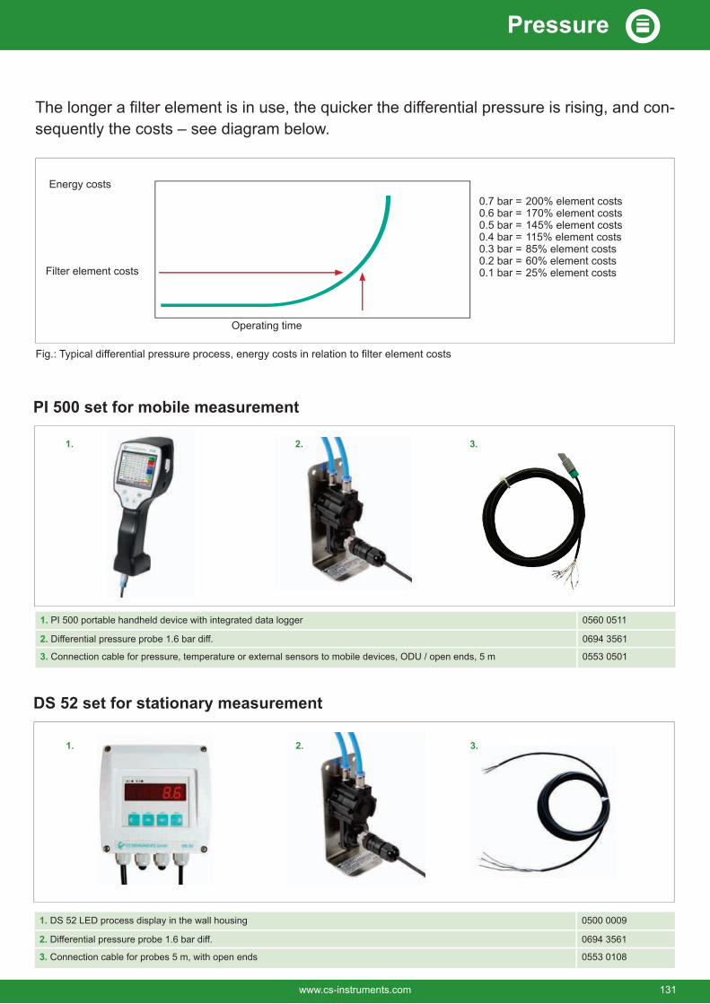
-sequently the costs – see diagram below.
0.7 bar = 200% element costs0.6 bar = 170% element costs0.5 bar = 145% element costs0.4 bar = 115% element costs0.3 bar = 85% element costs0.2 bar = 60% element costs0.1 bar = 25% element costs
Operating time
Filter element costs
Energy costs
Fig.: Typical differential pressure process, energy costs in relation to filter element costs
3
1. DS 52 LED process display in the wall housing 0500 0009
2. 0694 3561
3. Connection cable for probes 5 m, with open ends 0553 0108
DS 52 set for stationary measurement
1. PI 500 portable handheld device with integrated data logger 0560 0511
2. 0694 3561
3. Connection cable for pressure, temperature or external sensors to mobile devices, ODU / open ends, 5 m 0553 0501
PI 500 set for mobile measurement
1. 2. 3.
1. 2. 3.
www.cs-instruments.com 131
Pressure

SALES OFFICE NORTHCS INSTRUMENTS GmbH & Co. KGGewerbehof 1424955 HarrisleeGermanyTel.: +49 (0)461 807 150-0Fax: +49 (0)461 807 150-15E-mail: [email protected].: www.cs-instruments.com
SALES OFFICE SOUTHCS INSTRUMENTS GmbH & Co. KGZindelsteiner Straße 1578052 VS-TannheimGermanyTel.: +49 (0)7705 978 99-0Fax: +49 (0)7705 978 99-20E-mail: [email protected].: www.cs-instruments.com
Headquarters Germany
FRANCECS INSTRUMENTS4, rue du docteur Heulin75017 ParisFrancePhone: +33 1 86 95 87 60E-mail: [email protected].: www.cs-instruments.com/fr
ITALYCS INSTRUMENTS Italia S.r.l.Via Matteotti 6620092 - Cinisello Balsamo (Mi)ItalyPhone: +39 0225061761E-mail: [email protected].: www.cs-instruments.com/it
NETHERLANDSCS INSTRUMENTS BENELUX BVKorhoenweg 154791 RM KlundertNetherlandsPhone: +31 (0)168 382 699E-mail: [email protected].: www.cs-instruments.com/nl
AUSTRIACS INSTRUMENTS GmbHFabriksgasse 68600 Bruck an der MurAustriaPhone: +43 (0)664 181 3284E-mail: [email protected].: www.cs-instruments.com/at
SWITZERLAND
Mühlegasse 83237 BrüttelenSwitzerlandPhone: +41 32 355 4160E-mail: [email protected].: www.cs-instruments.com/ch
SPAINCS INSTRUMENTS, S.L.Avda. Cerro Milano 4, Local 128051 MadridSpainPhone: +34 91 33 15 758E-mail: [email protected].: www.cs-instruments.com/es
SOUTH AFRICA
142 Briza Road, Table View7441 Cape TownSouth AfricaPhone: +27 (0)21 557 56 18E-Mail: [email protected].: www.cs-instruments.com/za
Subsidiaries of CS INSTRUMENTS
Sales / technology Order processing and recalibration
SALES PARTNER USASIGA Developments LLC5460 33rd. Street SEGrand Rapids, MI 49512USAPhone.: +1 616 828 1024E-Mail: [email protected].: www.sigacas.com
TURKEY
Aeropark Kat-5
Phone: +90 216 251 67 58E-mail: [email protected].: www.cs-instruments.com/tr
132 www.cs-instruments.com