Embed Size (px)
Citation preview

FLOWTECHNIK
FLOWTECHNIK
Section 3
Variable Area Flowmeters
Paddle Flow Switch
Pelton Wheel Flowmeters
Axial Turbine Flowmeter
Positive Displacement Flowmeters
Magnetic Inductive Flowmeters
Ultrasonic Flowmeters
Vortex Flowmeters
Coriolis Flowmeters
Sight Flow Indicators
Level Sensors, Switches & Controllers
Temperature Transmitters
Instrumentation
HYDROTECHNIK UK LtdUnit 10 Easter ParkLenton Lane Industrial EstateNottinghamNG7 2PX
Freephone: Tel: Fax: Email: Email: Web:
0800 068 4134 +44 (0)115 9003 550 +44 (0)115 9705 597 [email protected] [email protected] www.hydrotechnik.co.uk
HYDROTECHNIK

Hydrotechnik UK
89
Flowtechnik Catalogue - Contents
Variable Area Flowmeters- Variable area flowmeters - Principle of Operation 91
- M10, M11, M12 & M13 series float style variable area flowmeters 92
- M123 series plastic float style variable area flowmeters & switches 93
- M123 series plastic float style variable area flowmeters & switches 94
- M335 series plastic float style variable area flowmeters & switches 95
- M335 series plastic float style variable area flowmeters & switches 96
- CV series ClearView Variable Area flowmeter 97
- B series Variable Area flowmeter for liquids 98-99
- G series Variable Area flowmeter for air & gases 100-101
- H & J series Variable Area flowmeter for liquids or gases (High Temperature) 102
- M & N series Variable Area switching flowmeter for liquids & gases 103
- R series Variable Area flow transmitter for liquids & gases 104
- C series Variable Area flowmeter for case drain monitoring 105
- HYDRAPRO Flow, Pressure & Temperature test kit with loading valve 106
Paddle Flow Switch- PSF50 Paddle flow switch 107
Pelton Wheel Flowmeters- Pelton Wheel flowmeter - Principle of Operation 108
- Flowstat Pelton Wheel flowmeter 109
- TM Mini Turbopulse Pelton Wheel flowmeter 110
- SPX, SPT & SES series Pelton wheel flowmeter 111
- IP80 Insertion Paddlewheel flow sensor 112
- DP series Insertion Pelton Wheel flowmeter 113-114
Axial Turbine Flowmeter- Axial turbine flowmeters - principle of operation 115
- TM, 01A & 01N series low cost turbine flowmeters 116
- A1 commercial grade LCD turbine flowmeters 117
- G2 series industrial LCD turbine flowmeters 118-119
- RN3, 4 & 7 Stainless Steel turbine flowmeters 120-121
- RN3 & 4 Stainless Steel turbine flowmeters for Subsea applications 122
- TP Turbopulse series Turbine flowmeters 123-124
Positive Displacement Flowmeters- Positive displacement flowmeters - principle of operation 125
- LLJ-120L Nutating disc positive displacement fuel totalising flowmeter 126
- FM-300 Nutating disc flowmeter for chemicals 126
- EM series OEM style Oval gear positive displacement flowmeters 127
- LM50 series Oval gear positive displacement flowmeters with LCD or Mechanical display 128
- 0M004, 006 & 008 Small capacity Oval gear positive displacement flowmeters 129-130
- 0M015, 025, 040 & 050 Medium capacity Oval gear positive displacement flowmeters 131-132
- 0M080 & 0M100 Large capacity Oval gear positive displacement flowmeters 133-134
- Y Strainers for Positive displacement meters 135
- Flowal series Oval gear positive displacement flowmeters in PP & PVDF 136
- OAP series Large diameter Oval gear positive displacement flowmeters 137-138
- ZHA series Aluminium circular gear positive displacement flowmeter 139
- ZHM series Stainless steel circular gear positive displacement flowmeter 140
- VS series Cast iron or Stainless steel circular gear positive displacement flowmeter 141
- SRZ series Helical screw positive displacement flowmeter 142
Magnetic Inductive Flowmeters- Magnetic Inductive Flowmeters - principle of operation 143
- PE102 series PVDF low flow magnetic inductive flowmeters 144
- WMP series polypropylene magnetic inductive flowmeters 145

Hydrotechnik UK
90
Flowtechnik Catalogue - Contents
- WMP series polypropylene magnetic inductive flowmeters 146
- EX80 series insertion style magnetic inductive flowmeters 147
- FN20 series industrial magnetic inductive flowmeters 148
- FF10 series hygenic magnetic inductive flowmeters 149
Ultrasonic Flowmeters- Ultrasonic flowmeters - principle of operation 150
- SL1168P Portable clamp on ultrasonic flowmeter kit 151
- FL series in-line Ultrasonic flowmeter 152
Vortex Flowmeters- Vortex flowmeters - principle of operation 153
- VA series Vortex flowmeters 154
Coriolis Flowmeters- Coriolis flowmeters - principle of operation 155
- KCM C-flow series Coriolis flowmeters 156
Sight Flow Indicators- Sight Flow Indicators - principle of operation 157
- Vista Ball sight flow indicators 158
- GP, GR & GP series Gunmetal sight flow indicators 159
- 881 series sight glass flowmeters in cast iron, steel or stainless steel 160
- 880 series flanged sight glass flowmeters in cast iron, steel or stainless steel 161
Level Sensors, Switches & Controllers- LCSFS series side mounted float level switches 162
- LCSF series top & side mounting float level switches 163
- LCF series two point float level controller 164
- LCSF100 series float level transmitter 165
- MG1 series guided wave radar level sensor 166
- LCSP series Hydrostatic level sensor 167
Temperature Transmitters- TSOK series OEM style temperature transmitter 168
- PPL8 series Pt100 & Pt1000 temperature transmitter 169
- PPL8 series type J, K & T thermocouple temperature transmitter 170
Instrumentation- RT38 low cost miniature DIN programmeable LED display 171
- TI08 low cost programmeable LED display 172
- CUB5 low cost dual input LCD rate & total display 173
- PAX series analogue, frequency single & dual input LED rate & total display 174
- FT400 series wall mounting frequency LCD rate & totalising display 175
- BT universally mounting totalising LCD display 176-177
- RT universal or DIN mount dual input rate & total LCD display 178-179
- CT34 low cost pulse counter, RPM meter & batch controller 180
- FT500 series wall mount batch controller 181
- EB series two stage batch controller 182-183
- A055 series Wall mount frequency to analogue convertor 184
- PS40 wall mounted pulse splitter & PD10 wall mounted pulse divider 185
- DL76 Wall mounting pulse datalogger 186
- SRD-99 series multichannel analogue datalogging LCD display & software 187-188
- Notes 189

Hydrotechnik UK
91
Variable Area Flowmeters
Variable Area flowmeters - Principle of Operation
Variable Area Flowmeters or Rotameters as they are sometimes known were first patented at the turn of the 19th Century. Consisting of a conical shaped tube, in which a spherical or conical float moves up and down, the distance the float moves up the tube being proportional to the flow rate of the fluid passing.
Generally they are used for low viscosity liquids (water like) or gases, must be installed vertically with flow from below and are either viewed by looking through the clear body (made of glass or plastic) across the top of the float or via a magnetically coupled pointer against a scale for metal bodied version.
Common variations include cylindrical metal tube versions with an internal cone, with the addition of a spring, the flowmeter can be mounted horizontally or vertically with flow downwards. A sharp edged orifice can also be included in the float which in combination with the spring allows the VA meter to reliably measure higher viscosity media such as oils. Inductive proximity switches, reed contacts or micro switches are often fitted to provide an alarm if the flow rates is below or exceeds a certain value.
Principle of operation
Principle of Variable Area flow movement
Oils Air/Gases Water Chemicals Fuels
Media application guide

Hydrotechnik UK
92
M10 to M13 flow meters work on the float principle and are used to measure the flow rate in closed pipelines. The medium flows through the vertically installed flow meter from bottom to top. This raises the float and shows the current flow rate on the scale on the measuring device. The read-off edge corresponds to the largest diameter of the float (ball).
Designation Material
Housing PMMA (Plexiglas)
Float Ball Stst 1.4571
Flow control PVC Stst 1.4571
O-ring (control) EPDM or FPM
Measuringrange H2O l/h
Measuring range air l/h, 0 bar
A x B L G G1M 10 with
controlM11 M12
M 13 withcontrol
1.5 – 15 100 – 700 25 x 25 105 R 1/4" R 5/8" 17.001.584 17.001.588 17.001.596 17.001.620
2.5 – 25 25 x 25 120 R 1/4" R 5/8" 17.001.565 17.001.589 17.001.597 17.001.621
5 – 50 100 – 2,000 25 x 25 120 R 1/4" R 5/8" 17.001.590 17.001.590 17.001.598 17.001.622
10 – 100 25 x 25 120 R 1/4" R 5/8" 17.001.591 17.001.591 17.001.599 17.001.623
• OEM Low cost design• Clear indication of flow rate• Optional needle valve• Water and air scales
M10, M11, M12 & M13 series float style variable area flowmeters
Variable Area Flowmeters
Material Data
Dimensional Information
Options & Ordering Information
M10 M12M11 M13

Hydrotechnik UK
93
Variable Area Flowmeters
M123 series plastic flow meters and switches are based on the well known suspended float principle. They are used for measuring and monitoring flows in closed pipes for both liquids & gases.
The media flows, from below, through a conical plastic measuring tube. This raises the float and the flow rate can be read off against the scale. The instruments can be fitted with bistable switches. The use of the high-quality material PVDF (model M123 3...) means that this type is suited for service with corrosive media
Technical DetailsMaterialsMeasuring tube: Trogamide T (M123 1..) or polysulfone (M123 2..) or PVDF (M123 3..)Float: PVDFO-rings: EPDM (M123-1..; M123-2..) FPM (M123-3..)Max. operating pressure: PN 10Max. operating temperature: M123 1... max. 60°C (0...60°C) M123 2... max. 100°C (0...100°C) (60°C with PVC screwed fitting) M123 3... max. 140°CAccuracy class: 4 (accord. to VDE/ VDI 3513, sheet 2)
Water l/h
0 barN m3/h
1 barN m3/h
2 barN m3/h
3 barN m3/h
4 barN m3/h
5 barN m3/h
6 barN m3/h
7 barN m3/h
8 barN m3/h
9 barN m3/h
10 barN m3/h
1.5-1.5 0.10-0.55 0.15-0.80 0.17-0.9 0.20-1.1 0.25-1.20 0.25-1.3 0.26-1.45 0.30-1.5 0.3-1.6 0.3-1.7 0.35-1.8
2.5-2.5 0.20-0.95 0.25-1.3 0.3-1.6 0.4-1.9 0.4-2.1 0.5-2.4 0.5-2.5 0.5-2.7 0.6-2.9 0.6-3.0 0.6-3.2
5-50 0.5-1.9 0.7-2.7 0.8-3.4 1.0-3.8 1.2-4.2 1.2-4.6 1.2-5.0 1.4-5.4 1.4-5.8 1.6-6.0 1.6-6.4
10-100 0.8-3.0 1.0-4.2 1.2-5.4 1.4-6.4 1.6-7.0 1.6-7.4 2.0-8.0 2-8.8 2.0-9.0 2-10 2-10
8-80 0.6-2.8 0.8-4 1.0-5.0 1.2-5.6 1.4-6.4 1.4-7.0 1.5-7.5 1.5-8.0 1.5-8.5 2.0-9.0 2.0-9.5
15-150 1.4-5.6 2-8 2-10 3-12 3-13 3-14 3.5-15 3.5-16.5 4-17 4-18 4-19
20-200 1.5-7.0 2-10 3-13 3-15 4-17 4-18 4-20 5-21 5-23 5-23 5-25
15-150 1.0-6.5 1-9 1.5-11 2-13 2-14.5 2-16 2-17 2.5-18 2.5-19.5 3-20 3-21
30-300 1.5-11 2-15 2.5-18 3-22 3-24 4-26 4-28 4-30 4-33 5-34 5-35
50-500 3-18 4-25 5-30 5-35 6-40 6-44 8-48 8-50 8-54 8-56 10-60
100-1000 6-30 8-44 10-54 12-62 12-70 15-75 15-80 15-85 20-90 20-95 20-100
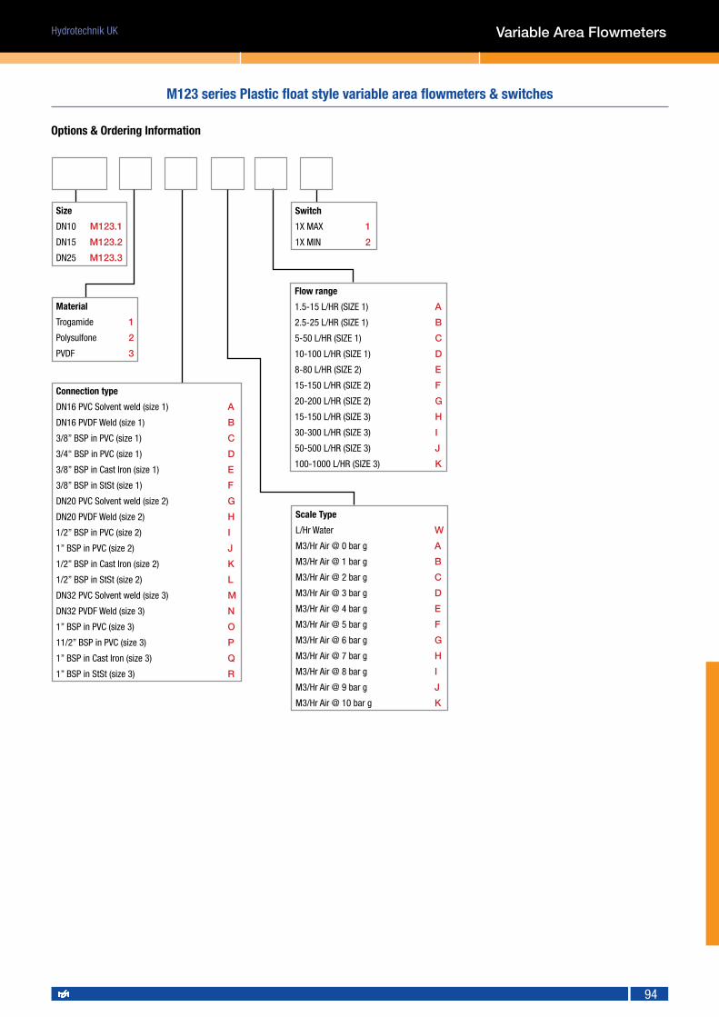
M123 series Plastic float style variable area flowmeters & switches
• Simple and clear to use• Good for polluted media (as long as not opaque)• Long scale length for good viewing• Chemically resistant materials for acids and bases
Flow Range Information for Water or Gases
Reed contacts (bistable)Switching voltage *: max. 130 VAC/0.5A/10 VAAllowed ambient temperature: 0...+55°CProtection: IP65Contact hysteresis: approximately 5-7mm Movement
Hydrotechnik UK
94
Variable Area Flowmeters
Size
DN10 M123.1
DN15 M123.2
DN25 M123.3
Switch
1X MAX 1
1X MIN 2
Connection type
DN16 PVC Solvent weld (size 1) A
DN16 PVDF Weld (size 1) B
3/8” BSP in PVC (size 1) C
3/4" BSP in PVC (size 1) D
3/8” BSP in Cast Iron (size 1) E
3/8” BSP in StSt (size 1) F
DN20 PVC Solvent weld (size 2) G
DN20 PVDF Weld (size 2) H
1/2” BSP in PVC (size 2) I
1” BSP in PVC (size 2) J
1/2” BSP in Cast Iron (size 2) K
1/2” BSP in StSt (size 2) L
DN32 PVC Solvent weld (size 3) M
DN32 PVDF Weld (size 3) N
1” BSP in PVC (size 3) O
11/2” BSP in PVC (size 3) P
1” BSP in Cast Iron (size 3) Q
1” BSP in StSt (size 3) R
Scale Type
L/Hr Water W
M3/Hr Air @ 0 bar g A
M3/Hr Air @ 1 bar g B
M3/Hr Air @ 2 bar g C
M3/Hr Air @ 3 bar g D
M3/Hr Air @ 4 bar g E
M3/Hr Air @ 5 bar g F
M3/Hr Air @ 6 bar g G
M3/Hr Air @ 7 bar g H
M3/Hr Air @ 8 bar g I
M3/Hr Air @ 9 bar g J
M3/Hr Air @ 10 bar g K
Flow range
1.5-15 L/HR (SIZE 1) A
2.5-25 L/HR (SIZE 1) B
5-50 L/HR (SIZE 1) C
10-100 L/HR (SIZE 1) D
8-80 L/HR (SIZE 2) E
15-150 L/HR (SIZE 2) F
20-200 L/HR (SIZE 2) G
15-150 L/HR (SIZE 3) H
30-300 L/HR (SIZE 3) I
50-500 L/HR (SIZE 3) J
100-1000 L/HR (SIZE 3) K
Material
Trogamide 1
Polysulfone 2
PVDF 3
Options & Ordering Information
M123 series Plastic float style variable area flowmeters & switches

Hydrotechnik UK
95
The plastic flow meters of model M335 are based on the float principle with the float moving freely without friction in the measuring tube. The indication point is at the greatest diameter of the float.
The standard flow meters are supplied with a scale for water (+20°C), a percentage scale, O-rings, two setpoint indicators and a guide rail for accessories. The measuring tube is available in PVDF (model M335-3...) for service with highly aggressive media, in polysulfone (M335-2...) for less aggressive media or in Trogamide (model M335-1...) for simple water or air applications.
The materials are resistant to impact, bending and compressive stresses. Optional threaded fittings can be fitted on the external threads. The floats are supplied with an integrated magnet for operation with a bistable reed contact.
Technical InformationHousing: M335-1...: Trogamide-T, M335-2...: Polysulfone, M335-3...: PVDF (translucent)Connections: G 1 1/2 to G 3 1/2 depending on the sizeFloat: PVDF, PVC (M335-x600...)Seals: EPDM (M335-1... / M335-2...) Viton (M335-3...)Max. temperature: M335-1...: 0-60°C, M335-2...: 0-100°C, M335-3...: 0-140°CMax. pressure: M335-1...: PN 16, M335-2...: PN 16, M335-3...: PN 10Accuracy: ±4% f. s.Reproducibility: 1%
Variable Area Flowmeters
Reed contact optionBistable reed contact N/O contact with increasing flowMax. ambient temperature: 0-55°CMax. power: 230 VAC 10 W / 12 VA 0.5 AHysteresis: approx. 3-12 mm float travelProtection: IP 65(To retrofit an instrument with a contact the float must be replaced with a float with integral magnet)
Measuring rangeH2O l/h
Air 0 barN m3/h
Air 1 barN m3/h
Air 2 barN m3/h
Air 3 barN m3/h
Air 4 barN m3/h
Air 5 barN m3/h
Air 6 barN m3/h
Air 7 barN m3/h
Air 8 barN m3/h
HCI 30-33%
l/h
NaOH 30%
l/h
NaOH 50%
l/h
50-500
100-1000
1.5-14
2.5-29
3-20
4-41
3-24
5-50
3-28
5-58
4-31
6-65
4-34
7-71
5-37
7-76
5-39
8-82
4.5-42
7.5-87
20-405
55-866
4-226
15-600
1-55
3-192
150-1500
250-2500
4-457-79
6-6310-111
7-7712-136
8-9014-158
9-10016-177
10-11018-193
11-11919-209
12-12720-223
12-13521-237
90-1340165-2310
30-97070-1800
6-36515-770
200-2000
300-3000
600-6000
6-58
9-108
17-174
9-8213-15224-246
11-10016-18630-301
12-11618-21634-348
14-13021-24139-389
15-14223-26442-426
16-15324-28645-426
17-16426-30549-492
18-17427-32451-522
115-1660190-3050420-4900
35-124075-2370230-4000
8-52015-117050-2270
600-6000
1000-10000
1500-15000
17-175
29-301
53-405
24-247
41-425
75-572
30-302
51-520
92-700
34-350
58-602
106-810
39-392
65-674
119-907
42-428
72-737
130-992
45-463
77-797
141-1073
49-495
83-851
150-1146
51-525
87-903
159-1.215
430-5090
750-9460
1415-11570
240-4700
475-7340
1030-10330
55-2300
140-4340
420-5820
2000-20000
3000-30000
8000-60000
55-54580-758
-
78-770113-1072
-
96-942139-1311
-
110-1090160-1516
-
124-1220180-1697
-
135-1335197-1857
-
146-1444212-2008
-
156-1542227-2145
-
165-1.635240-2.274
-
1500-173002175-24120
-
915-117201195-16040
-
245-7590400-11120
-
M335 series plastic float style variable area flowmeters & switches
Flow Range Information for Water or Gases

Hydrotechnik UK
96
Size
DN25 M335.1
DN32 M335.2
DN40 M335.3
DN50 M335.4
DN65 M335.5
Switch
1X MAX 1
1X MIN 2
Connection type
DN32 PVC Solvent weld (size 1) A
DN32 PVDF Weld (size 1) B
1” BSP in PVC (size 1) C
1” BSP in Cast Iron (size 1) D
1” BSP in StSt (size 1) E
DN40 PVC Solvent weld (size 2) F
DN40 PVDF Weld (size 2) G
11/4” BSP in PVC (size 2) H
11/4” BSP in Cast Iron (size 2) I
11/4” BSP in StSt (size 2) J
DN50 PVC Solvent weld (size 3) K
DN50 PVDF Weld (size 3) L
11/2” BSP in PVC (size 3) M
11/2” BSP in Cast Iron (size 3) N
11/2” BSP in StSt (size 3) O
DN65 PVC Solvent weld (size 4) P
DN65 PVDF Weld (size 4) Q
2” BSP in PVC (size 4) R
2” BSP in Cast Iron (size 4) S
2” BSP in StSt (size 4) T
DN75 PVC Solvent weld (size 5) U
DN75 PVDF Weld (size 5) V
21/2” BSP in PVC (size 5) W
21/2” BSP in Cast Iron (size 5) X
21/2” BSP in StSt (size 5) Y
Scale Type
L/Hr Water A
L/Min Water B
M3/Hr Water C
L/Hr HCL 30-33% D
L/Hr NaOH 30% E
L/Hr NaOH 50% F
M3/Hr Air @ 0 bar g G
M3/Hr Air @ 1 bar g H
M3/Hr Air @ 2 bar g I
M3/Hr Air @ 3 bar g J
M3/Hr Air @ 4 bar g K
M3/Hr Air @ 5 bar g L
M3/Hr Air @ 6 bar g M
M3/Hr Air @ 7 bar g N
M3/Hr Air @ 8 bar g O
Flow range
50-500 L/HR (SIZE 1) A
100-1000 L/HR (SIZE 1) B
150-1,500 L/HR (SIZE 2) C
250-2,500 L/HR (SIZE 2) D
200-2,000 (SIZE 3) E
300-3,000 L/HR (SIZE 3) F
600-6,000 L/HR (SIZE32) G
600-6,000 L/HR (SIZE 4) H
1,200-12,000 L/HR (SIZE 4) I
1,500-15,000 L/HR (SIZE 4) J
2,000-20,000 L/HR (SIZE 5) K
3,000-30,000 L/HR (SIZE 5) L
6,000-60,000 L/HR (SIZE 5) M
Material
Trogamide 1
Polysulfone 2
PVDF 3
M335 series plastic float style variable area flowmeters & switches
Variable Area Flowmeters
Options & Ordering Information

Hydrotechnik UK
97
Ideal for OEM water and lubrication oil applications with a simple clear moulded body allowing visual inspection of the fluid. Available in 1/2", 3/4" or 1" connections with polysulphone or brass connectors. Flows from 2 to 110 l/min. Max pressure 22.4 bar.
Variable Area Flowmeters
Measuring accuracy: ±5% of full-scale
Repeatability: ±1% of full-scale
Flow measuring range: (5-110 LPM)
Turn down ratio (all ranges) 10:1
Maximum operating pressure: 22.4 Bar)
Maximum operating temperature: Clearview H20 (93°C)Clearview+ (121°C)
Filtration requirements: 74 micron filter or 200 mesh screen minimum
ClearView H2O ClearView +
End Ports Brass, Polysulphone Brass, Polysulphone
Seals Buna-N Buna-N
Spring Stainless Steel Stainless Steel
Body Polycarbonate Polysulphone
Indicator Polysulphone Polysulphone
DIM 1/2" Female 3/4" Female 1" Female
A 2-7/16" (62mm) 2-7/16" (62mm) 2-7/16" (62mm)
B 7-5/32" (182mm) 7-9/16" (192mm) 7-9/16" (192mm)
Port type NPTF, BSPP NPTF, BSPP NPTF, BSPP
Options & Ordering Information
Body Material
Polycarbonate H20 CVC
Polysulphone + CVP
Connection type
Female NPT threads (brass) N
Female BSP threads (brass) B
Female NPT threads (polysulphone) S
Female BSP threads (polysulphone) R
Media calibration
Hydraulic oil H
Water W
Nominal port size
1/2" 3
3/4" 4
1" 5
Flow ranges l/min
0.5-5 GPM (2-20) 05
1-10 GPM (4-40) 10
1-15 GPM (4-60) 15
3-30 GPM (11-110) 30
CV series ClearView Variable Area flowmeter
ClearView in-line flow monitors (style CV)
• Universal mounting• Choice of 2 materials• 4 flow ranges for water oil• Compact & economic design
Technical Data
Material Data Dimensional Data

Hydrotechnik UK
98
Universal flowmeter for water and oil applications. High pressure design for up to 414 Bar, with a choice of threads from 1/4" up to 2" in BSP, NPT or SAE and flow ranges up to 570 L/Min. Available in Aluminium, Brass or Stainless Steel.
Measuring accuracy: ±2.5% of full-scale in the centre third of the measuring range; ±4% in upper and lower thirds
Repeatability: ±1% of full-scale
Flow measuring range: 0.2-560 LPM
Maximum operating pressure: aluminium and brass monitors; 240 Bar stainless steel monitors; 410 Bar
Maximum operating temperature: 116°C Note: for operation to 316°C see H&J series
Filtration requirements: 74 micron filter or 200 mesh screen minimum
Variable Area Flowmeters
Aluminum Brass Stainless Steel
High-pressure casing, end ports and tapered shaft
Aluminum Brass #303 Stainless Steel
Seals Buna-N (STD), EPR,Viton® or Kalrez®
Buna-N (STD), EPR, Viton® with Teflon®
Transfer Magnet Teflon® coated Alnico Teflon® coated Alnico Teflon® coated Alnico
Floating Orifice Disk Stainless Steel Stainless Steel Stainless Steel
All other internal parts Stainless Steel Stainless Steel Stainless Steel
B series Variable Area flowmeter for liquids
Technical Data
Basic in-line flow monitors (style B)
• Choice of 3 materials of construction • Universal mounting• Rugged and reliable design• High pressure up to 414 Bar
Material Data
Dimensional Data
Dim Size 3 Size 4 Size 5 Size 5 (2")
A 48mm 60mm 90mm 90mm
B 167MM 182mm 258mm 322mm
Port sizes NPTF: 1/4’, 3/8”, 1/2” SAE: #6, #8, #10 BSP: 3/8”, 1/2”
NPTF: 3/4”, 1” SAE: #12, #16BSP: 3/4”, 1”
NPTF: 1-1/4”, 1-1/2” SAE: #20, #24
BSP: 1-1/4”, 1-1/2”
NPTF: 2”SAE: #32 BSP: 2”

Hydrotechnik UK
99
Options & Ordering Information
Style
Basic in-line for liquid B
Meter size codeInches
1/4” to 1/2” 3
3/4” to 1 4
11/4” to 2 5
Thread type: Porting
All female Size Code
1/4” BSP 3 only &(British Standard Pipe)
3/8” BSP 3 only R
1/2” BSP 3 only T
3/4” BSP 4 only U
1” BSP 4 only V
11/4” BSP 5 only W
11/2” BSP 5 only Y
2” BSP 5 only XNote: NPT & SAE threaded porting available on request
Flow ranges
l/min for sizes
0.2–4 3 only 01
0.4–4 (water) 3 only
0.8–8 3 and 4 02
1.9–19 3 only 05
3.8–38 3 and 4 10
3.8–57 3 and 4 15
7.6–76 4 only 20
7.6–95 4 and 5 25
11–110 4 only 30
15–150 4 only 40
19–190 4 only 50
30–280 5 only 75
38–380 5 only 88
76–570 5 only 99
Material
Aluminium A
Brass B
Stainless steel S
Pressure rating
241 Bar 6(Liquids / aluminium and brass)
414 Bar 7(Liquids / stainless steel)
Fluid media
Oil and 0.873 specific gravity H
Water and 1.0 specific gravity W
Style
Standard, uni-directional --
Bi-directional* BI
Reverse* RF*Not all flow ranges are available with Bi-directional and Reverse flow options. Please consult Flowtechnik for availability and delivery time.
Variable Area Flowmeters
B series Variable Area flowmeter for liquids

Hydrotechnik UK
100
Measuring accuracy: ±2.5% of full-scale in the centre third of the measuring range; ±4% in upper and lower thirds
Repeatability: ±1% of full-scale
Flow measuring range: 1.5 - 1300 SCFM @ 100 PSIG
Maximum operating pressure: aluminium and brass monitors; 40 Bar stainless steel monitors; 70 Bar
Maximum operating temperature: 116°C Note: for operation to 600°F (316°C) see H&J series
Standard calibration data Air @ 70°F (21°C), 1.0sg and 100 PSIG (6.8 Bar)
Filtration requirements: 74 micron filter or 200 mesh screen minimum
Aluminum Brass Stainless Steel
High-pressure casing, end ports and tapered shaft
Aluminum Brass #303 Stainless Steel
Seals Buna-N (STD), EPR,Viton® or Kalrez®
Buna-N (STD), EPR, Viton® with Teflon®
Transfer Magnet Teflon® coated Alnico Teflon® coated Alnico Teflon® coated Alnico
Floating Orifice Disk Stainless Steel Stainless Steel Stainless Steel
All other internal parts Stainless Steel Stainless Steel Stainless Steel
G series Variable Area flowmeter for air & gases
Variable Area Flowmeters
Universal flowmeter for air and gas applications. High pressure design for up to 70 Bar, with a choice of threads from 1/4" up to 2" in BSP, NPT or SAE and flow ranges up to 1300 scfm. Available in Aluminium, Brass or Stainless Steel.
Basic in-line flow monitors (style G)
• Choice of 3 materials of construction • Universal mounting• Rugged and reliable design • High pressure up to 1000 psi (70 bar)
Technical Data
Material Data
Dimensional Data
Dim Size 3 Size 4 Size 5 Size 5 (2")
A 48mm 60mm 90mm 90mm
B 167MM 182mm 258mm 322mm
Port sizes NPTF: 1/4’, 3/8”, 1/2” SAE: #6, #8, #10 BSP: 3/8”, 1/2”
NPTF: 3/4”, 1” SAE: #12, #16BSP: 3/4”, 1”
NPTF: 1-1/4”, 1-1/2” SAE: #20, #24
BSP: 1-1/4”, 1-1/2”
NPTF: 2”SAE: #32 BSP: 2”

Hydrotechnik UK
101
Options & Ordering Information
Variable Area Flowmeters
G series Variable Area flowmeter for air & gases
Options & Ordering Information
Style
Pnuematic for air and gas G
Meter size codeInches
1/4” to 1/2” 3
3/4” to 1 4
11/4” to 2 5
Thread type: Porting
All female Size Code
1/4” BSP 3 only &(British Standard Pipe)
3/8” BSP 3 only R
1/2” BSP 3 only T
3/4” BSP 4 only U
1” BSP 4 only V
11/4” BSP 5 only W
11/2” BSP 5 only Y
2” BSP 5 only XNote: NPT & SAE threaded porting available on request
Flow ranges
SCFM for sizes
1.5-12 3 only 01
4-23 3 and 4 02
5–50 3 only 05
10–100 3 and 4 10
15–150 3 and 4 15
20–215 4 only 20
20–250 4 and 5 25
30–330 4 only 30
30–400 4 only 40
40–500 4 only 50
30–750 5 only 75
150–900 5 only 88
150–1300 5 only 99
Material
Aluminium A
Brass B
Stainless steel S
Pressure rating
41 Bar 4(Air and gas/aluminium and brass)
69 Bar 5(Air and gas/stainless steel and brass)
Fluid media
Air and gases A
Style
Standard, uni-directional --
Bi-directional* BI
Reverse* RF*Not all flow ranges are available with Bi-directional and Reverse flow options. Please consult Flowtechnik for availability and delivery time.

Hydrotechnik UK
102
High temperature in-line flow monitors (Style H & J)
Measuring accuracy: ±2.5% of full-scale in the centre third of the measuring range; ±4% in upper and lower thirds
Repeatability: ±1% of full-scale
Flow measuring range: (0.2-560 LPM)
Maximum operating pressure: aluminium and brass monitors; 240 Bar stainless steel monitors; 414 Bar
Maximum operating temperature: Style H - 204°C, Style J - 315°C
Filtration requirements: 74 micron filter or 200 mesh screen minimum
Options & Ordering Information
Style Hi-temp 204°C in-line H
Hi-temp 315°C in-line J
Meter size codeInches 1/4” to 1/2” 3
3/4” to 1 4
11/4” to 2 5
Thread type: PortingAll female Size Code 1/4” BSP 3 only &(British Standard Pipe)
3/8” BSP 3 only R
1/2” BSP 3 only T
3/4” BSP 4 only U
1” BSP 4 only V
11/4” BSP 5 only W
11/2” BSP 5 only Y
2” BSP 5 only XNote: NPT & SAE threaded porting available on request
Material Aluminium A
Brass B
Stainless steel S
Pressure rating 41 Bar 4(Air & gas / aluminium and brass)
69 Bar 5(Air & gas / stainless steel)
241 Bar 6(Liquids / aluminium and brass)
414 Bar 7(Liquids / stainless steel)
Fluid media Air and gases A
Oil and 0.873 specific gravity H
Water and 1.0 specific gravity W
Flow rangesLiquid (oil and water) air (© 100 PSIG) for sizes Codel/min SCFM0.2–4 1.5–12 3 only 01
0.4–4 (water) 3 only
0.8–8 4–23 3 and 4 02
1.9–19 5–50 3 only 05
3.8–38 10–100 3 and 4 10
3.8–57 15–150 3 and 4 15
7.6–76 20–215 4 only 20
7.6–95 20-250 4 and 5 25
11–110 30–330 4 only 30
15–150 30–400 4 only 40
19–190 40–500 4 only 50
30–280 30–750 5 only 75
38–380 150–900 5 only 88
76–570 150–1300 5 only 99
Style Standard, uni-directional --
Bi-directional* BI
Reverse* RF*Not all flow ranges are available with Bi-directional and Reverse flow options. Please consult Flowtechnik for availability and delivery time.
Variable Area Flowmeters
H & J series Variable Area flowmeter for liquids or gases (High Temperature)
Enables flow monitoring of barrel heating fluids, thermal transfer fluids such as Syltherm®coolant flows through heat exchangers, as well as flows through hydraulic circuits and sub-circuits with elevated temps up to 315°C.
• Choice of 3 materials of construction • Universal mounting• Rugged and reliable design• High temperature up to 315°C

Hydrotechnik UK
103
Measuring accuracy: ±2.5% of full-scale in the centre third of the measuring range; ±4% in upper and lower thirds
Repeatability: ±1% of full-scale
Flow measuring range: 0.2-560 LPM; 1.5-1300, SCFM
Maximum operating pressure: aluminium and brass 240 Bar, stainless steel 414 Bar
Standard calibration fluids: Oil monitors: DTE 25 @ 43°C, 0.873sg Water monitors: tap water @ 21°C, 1.0sg
Enclosure: NEMA type 4X (UL Approved)
Alarm switch dead-band: 4% of full scale
Alarm switch contacts: SPDT (dry contact), UL/CSA rating: 10 amps and 1⁄4 hp, 125 or 250 VAC. 1⁄2 amp, 125 VDC; 1⁄4 amp, 250 VDC; 3 amps, 125 VAC ‘L” (lamp load)
• One (M) or two (N) settable switching points • Universal mounting• Economic, rugged and reliable design • High pressure up to 414 Bar
Options & Ordering Information
Style Standard, uni-directional --
Bi-directional* BI
Reverse* RF
*Not all flow ranges are available with Bi-directional and Reverse flow options. Please consult Flowtechnik for availability and delivery time.
Thread type: PortingAll female Size Code 1/4” BSP 3 only &(British Standard Pipe)
3/8” BSP 3 only R
1/2” BSP 3 only T
3/4” BSP 4 only U
1” BSP 4 only V
11/4” BSP 5 only W
11/2” BSP 5 only Y
2” BSP 5 only X
Note: NPT & SAE threaded porting available on request
Flow rangesLiquid (oil and water) air (© 100 PSIG) for sizes Codel/min SCFM0.2–4 1.5–12 3 only 01
0.4–4 (water) 3 only
0.8–8 4–23 3 and 4 02
1.9–19 5–50 3 only 05
3.8–38 10–100 3 and 4 10
3.8–57 15–150 3 and 4 15
7.6–76 20–215 4 only 20
7.6–95 20-250 4 and 5 25
11–110 30–330 4 only 30
15–150 30–400 4 only 40
30–280 30–750 5 only 75
38–380 150–900 5 only 88
76–570 150–1300 5 only 99
Style Flow alarms 1 switch M
Flow alarms 2 switches N
Meter size codeInches 1/4” to 1/2” 3
3/4” to 1 4
11/4” to 2 5
Material Aluminium A
Brass B
Stainless steel S
Pressure rating 41 Bar 4(Air & Gas / aluminium and brass)
69 Bar 5(Air & Gas / stainless steel)
241 Bar 6(Liquids / aluminium and brass)
414 Bar 7(Liquids / stainless steel)
Fluid media Air and water A
Oil and 0.873 specific gravity H
Water and 1.0 specific gravity W
Dim Size 3 Size 4 Size 5 Size 5 (2")
A 167mm 182mm 258mm 322mm
B 56mm 75mm 97mm 97mm
C 101mm 114mm 135mm 135 mm
D 47mm 47mm 47mm 47mm
E 128mm 127mm 172mm 172mm
F 57mm 73mm 95mm 95mm
Port sizes 1/4”, 3/8”, 1/2” 3/4”, 1” 1-1/4”, 1-1/2” 2”
Variable Area Flowmeters
In-line flow rate switches (Style M & N)
M & N series Variable Area switching flowmeter for liquids or gases
Dimensional Data

Hydrotechnik UK
104
Measuring accuracy: ±2.5% of full-scale in the centre third of the measuring range; ±4% in upper and lower thirds
Repeatability: ±1% of full-scale
Flow measuring range: 0.2-560 LPM; 1.5-1300, SCFM
Maximum operating pressure: aluminium and brass monitors; 240 Bar stainless steel monitors; 410 Bar
Maximum operating temperature: media: 116°C, ambient: 82°C
Standard calibration fluids: Oil monitors: DTE 25 @ 43°C, 0.873sg Water monitors: tap water @ 21°C, 1.0sg
Filtration requirements: 74 micron filter or 200 mesh screen minimum
Signal outputs 4-20mA, 0-5Vdc, 1-5Vdc,and square wave pulse outputs.
Options & Ordering Information
Style Standard, uni-directional --
Bi-directional* BI
Reverse* RF
*Not all flow ranges are available with Bi-directional and Reverse flow options. Please consult Flowtechnik for availability and delivery time.
Thread type: PortingAll female Size Code 1/4” BSP 3 only &(British Standard Pipe)
3/8” BSP 3 only R
1/2” BSP 3 only T
3/4” BSP 4 only U
1” BSP 4 only V
11/4” BSP 5 only W
11/2” BSP 5 only Y
2” BSP 5 only X
Note: NPT & SAE threaded porting available on request
Flow rangesLiquid (oil and water) air (© 100 PSIG) for sizes Codel/min SCFM0.2–4 1.5–12 3 only 01
0.4–4 (water) 3 only
0.8–8 4–23 3 and 4 02
1.9–19 5–50 3 only 05
3.8–38 10–100 3 and 4 10
3.8–57 15–150 3 and 4 15
7.6–76 20–215 4 only 20
7.6–95 20-250 4 and 5 25
11–110 30–330 4 only 30
15–150 30–400 4 only 40
30–280 30–750 5 only 75
38–380 150–900 5 only 88
76–570 150–1300 5 only 99
Style Transmitter R
Meter size codeInches 1/4” to 1/2” 3
3/4” to 1 4
11/4” to 2 5
Material Aluminium A
Brass B
Stainless steel S
Pressure rating 41 Bar 4(Air & Gas / aluminium and brass)
69 Bar 5(Air & Gas / stainless steel)
241 Bar 6(Liquids / aluminium and brass)
414 Bar 7(Liquids / stainless steel)
Fluid media Air and water G
Oil and 0.873 specific gravity H
Water and 1.0 specific gravity W
Variable Area Flowmeters
R series Variable Area flow transmitter for liquids or gases
• Selectable pulse, voltage or mA signal output of flow rate• Visual and electrical output of flow rate• Economic, rugged and reliable design• High pressure up to 414 Bar
In-line flow rate transmitter (Style R)
Dim Size 3 Size 4 Size 5 Size 5 (2")
A 167mm 182mm 258mm 322mm
B 56mm 75mm 97mm 97mm
C 101mm 114mm 135 mm 135 mm
D 47mm 47mm 47mm 47mm
E 128mm 127mm 172mm 172mm
F 57mm 73mm 95mm 95mm
Port sizes 1/4”, 3/8”, 1/2” 3/4”, 1” 1-1/4”, 1-1/2” 2”
Dimensional Data

Hydrotechnik UK
105
Measuring accuracy: ±5% of full-scale in the centre third of the measuring range
Repeatability: ±1% of full-scale
Flow measuring range: Up to 120 LPM
Maximum operating pressure: 69 Bar
Maximum operating temperature: 116°C
Standard calibration fluids: DTE 25 @ 43°C, 0.873sgWater monitors: tap water @ 21°C, 1.0sg
Filtration requirements: 74 micron filter or 200 mesh screen minimum
Variable Area Flowmeters
Our Case Drain monitor is a lower cost option to using our Basic In line (Style B) flowmeter for pump case drain applications.
Flow ranges 0.2-4 LPM = Code 01 3 only
0.8–8 LPM = 02 3 and 4
2–20 LPM = 05 3 and 4
4–40 LPM = 10 3 and 4
4-60 LPM = 15 3 and 4
8–80 LPM = 20 4 only
8–100 LPM = 25 4 only
12–120 LPM = 30 4 only
Port/Line size range 1/2” NPTF 3
3/4” to 1 NPTF 4
Material Aluminium A
Pressure rating 69 PSIG max. 5
Fluid media Oil H
Thread type: PortingAll female 1/2” NPTF, dry seal = B 3 only
3/4” NPT 4 only
1” NPT 4 only
Dim Size 3 Size 4
A 48mm 60mm
B 167mm 182mm
Port sizes NPTF: 1/2” NPTF: 3/4”, 1”
C series Variable Area flowmeter for case drain monitoring
Case Drain in-line Monitors (Style C)
• Helps confirm pump performance • Universal mounting• Rugged and reliable design • Low cost Aluminium design
Dimensional Data
Options & Ordering Information
Style Case Drain C

Hydrotechnik UK
106
Variable Area Flowmeters
Materials of constructionBody: 303 stainless steelPiston & cone: 2024-351 Aluminium, anodizedSpider plate: 316 stainless steelSpring: 302 stainless steelFasteners: 303 stainless steelPressure seals: VitonGuard: PolycarbonateRetaining ring: SAE 1070/1090 Carbon steelRetaining spring: SAE 1070/1090 Carbon steelIndicator & Internal Magnet: PPS/CeramicGuard/Bumper: Buna NScale Support: 6063-T6 AluminiumEnd caps: Nylon ST
Part number Connection size Flow range Pressure range Temp. range
HP.702.S.030.TKV 3/4” BSP 10...110 l/min 0...350 bar 0...120°C
HP.762.S.050.TKV 1” BSP 19...190 l/min 0...350 bar 0...120°C
Spare parts Description
F1614-6000 400 bar safety blow out discs (pack of 10)
• A complete troubleshooting system• Plan component repairs• Economical, compact and rugged• Non-electrical• Easy to use loading valve with safety blow out disc
HYDRAPRO Flow, Pressure & Temperature test kit with loading valve
HYDRAPRO Hydraulic Test Kits
Used to Diagnose faults in hydraulic circuits, determine hydraulic horsepower and test for component wear such as hydraulic valve and cylinder leakage
Technical data•Temperaturerange: -20to+116°C• Pressure rating: (3:1 safety factor) 3/4" through 11/2" sizes; 345 bar maximum• Pressure drop: on request• Accuracy: ±2% of full scale• Repeatability: ±1%• Threads: BSPP - NPT and SAE available upon request• Testkitpressuregauge - Glycerin filled: 0-400 bar (0-6000 psi)• Testkitloadvalve: Pressure compensated balanced, 414 bar
Options & Ordering Information
Supplied in sturdy carry case with foam insert

Hydrotechnik UK
107
Paddle Flow Switch
Economically priced flow/no flow paddle operated flow switch. Simple and reliable design for liquids up to 140°C. Operates with flow in both directions for installation on pipes from 1" to 3". IP65 protection housing with explosion proof version available.
Output type NO/NC reed contact, 230 VAC, 2A, 50 WOutput action activates at flow rate over set pointSet-point adjustment cut paddle lengthSet-point tolerance ± 25%Repeatability ± 5%
Operating InformationMedium type low-contaminated liquidProcess temperature -30...140 °C (-30...100 °C for Ex version)CIPtemperature up to 150 °CProcess pressure up to 25 barMax pressure drop max. 200 mbarAmbient temperature -40...85 °CAmbient humidity 0...95 %RH
Pipe diameter 1" 11/4" 11/2" 2" 21/2" 3"
Flow range (set-point) (l/min) ON OFF ON OFF ON OFF ON OFF ON OFF ON OFF
Paddle length
1" 20 16 33 25 47 35 66 58
11/4" 25 18 35 27 58 47 89 78
11/2" 54 39 89 62 124 97
2" 70 47 93 66 128 105
21/2" 78 50 105 85
3" 85 62
Process connection G1", 1" NPT
Electrical connection screw terminals inside the housing
Housing (protection) aluminium head type "G" (IP65) or ATEX-approved Ex 'd' head type "EG" (IP68)
Wetted parts 304 stainless steel (1.4301)
Weight max. 950 g
PSF50 Paddle flow switch
• Stainless Steel construction• Pipe sizes up to 3”• High temperature (max 140°C, 150°C for CIP)• EEx d version
Paddle flap flow / no flow switch
Operating principle paddle-operated magnet switchFlow range 15...130 l/minRange adjustment cut paddle length, 1...3"
Dimensional Data
Options & Ordering Information
Feature or option Order Code PSF-X.X
Housing G = IP65 head type "G", EG = IP68 ATEX approved Exd head type "EG"
Process Connection Q12 = G1" BSP, Q15 = 1" NPTExamplePSF50-G.Q12

Hydrotechnik UK
108
Pelton Wheel flowmeters - Principle of Operation
Pelton wheel flowmeters take their name from a type of water wheel patented in the late 19th Century. Although not true Pelton wheels, modern radial flow turbines use Pelton’s principles to harness the power of a jet of water directed at one side of a free running paddle wheel. The speed of rotation of the turbine is proportional to the velocity of the liquid passing through it.
This rotation is commonly sensed using embedded magnets and a Hall effect device. Optical pick-ups can also used. For lower flow rates the turbine is housed in an in-line body and with careful design, flow rates down to a teaspoon a minute can be measured. Higher flow rates and larger pipe sizes tend to use an insertion design which makes them very cost effective as the existing pipe becomes the body of the flowmeter.
Pelton wheels are used almost exclusively on water like liquids as they quickly become non-linear with even a modest increase in viscosity.
Principle of operation
Pelton Wheel Flowmeters
Principle of Pelton Wheel flow movement
Water Chemicals Fuels
Media application guide

Hydrotechnik UK
109
Output
Current C
Pulse P
Relay R
Voltage V
Options & Ordering Information
Whether it’s a unique flow monitoring application, a limited budget or both, the FlowStat and FlowStat ES is a perfect fit. FlowStat comes in a Stainless Steel body, the FlowStat ES version a durable polypropylene body for cost savings, and is compatible with a variety of fluids. The sensor offers a flow measuring accuracy of ±2% of full scale, and is capable of handing pressures up to 34 bar and temperatures up to 107°C. For additional compatibility, the FlowStat Sensor offers 4-20mA, 0-5 Vdc, pulse or relay outputs.
Dimensional Information
Flowstat
Flowstat ES
Economy Series (Polypropylene) = ES
Measuring accuracy: ±2% of full-scale
Repeatability: ±0.5% of full-scale
Flow measuring range: 1/2" porting, (2-60 LPM) 3/4”- 1” porting, (60-200 LPM)
Turndown ratio: 10:1
Temperature range: (-7 to 107oC) -7°C to 66°C (ES model)
Pressure range: to 34 Bar (10 bar ES model)
With/optional clear cover: to 14 Bar
Standard calibration mode: Water @ 20°C temperature
Filtration requirements: 74 micron filter or 200 mesh screen minimum
DIM 1/2" NPTF 3/4" NPTF - 1 NPTF
A 1.94” (49mm) 3.06” (78mm)
B 1.13” (29mm) 1.33” (34mm)
C 2.00” (51mm) 2.46” (62mm)
D 2.45” (62mm) 2.78” (71mm)
D* 2.45” (62mm) 2.88” (73mm)
E 3.70” (94mm) 5.25” (133mm)
F 2.63” (67mm) 3.80” (97mm)
* Dimensions with optional clear polycarbonate cover installed
Important: Choose a maximum flow rate, for 1/2” NPT: 20 up to 60 maximum LPM, for 3/4” and 1” NPT: 60 up to 200 maximum LPM. Minimum flow rate will be 10% of maximum flow rate. Example: If your maximum flow rate is 80 LPM, the minimum flow rate would be 8 (80x.1=8). Thus, the correct flow rate would be 8-80 LPM.
Pelton Wheel Flowmeters
• Stainless Steel or Polypropylene Design• Pulse, Analogue or switch outputs• Flows up to 200 L/Min• Optional sight glass cover
Rotor cover
316 Stainless S
Clear Polycarbonate C
Port size
1/2" NPT B
3/4" NPT C
1" NPT D
Cover seal
Buna-N (Standard) B
EPR (Optional) E
VIton (Optional) V
Maximum flow rate: LPM
1/2" NPT 20 LPM max up to 60 LPM max flow rates available =
3/4" & 1" NPT 60 LPM max up to 200 LPM max flow rates available =
Recommended Instruments: FBT11, FRT12, FEB10
Flowstat Pelton wheel flowmeter
Technical Information

Hydrotechnik UK
110
Pelton Wheel Flowmeters
The TM series flowmeter is designed to give high performance and competitive pricing with 6 flow ranges from 0.05 to 15 litres per minute. Its choice of materials makes this the ideal choice for the metering of aggressive chemicals including ultra-pure water. The standard inlets are 1/4” BSP F although for OEM use alternatives are available.
The bearings are made of sapphire for long life and reliability, the body is either PVDF or 316 stainless steel and as standard and the ‘O’ ring seal is typically Viton™.
Model Flow rangeL/Min
Linearity% FSD
TypicalFreq. Hz.
Approx‘K’ Factor
TM001 0.05-0.5 2.0 142 17000
TM002 0.12-1.5 2.0 175 7000
TM003 0.2-4.5 1.5 260 3500
TM004 0.25-6.5 1.5 230 2100
TM005 0.3-10 1.0 235 1420
TM006 0.5-15 1.0 245 980
Recommended Instruments: FBT11, FRT12, FEB10
TP-Turbopulse Mini
Nominal sizes (1/4"BSPF)
Accuracy @ 1cp ± 1-2% FSD
Temperature range -5~125°C
Maximum pressure
316 stainless steel 10 bar
Peek 10 bar
Protection class IP66/67 (NEMA4X)
Electrical
standard output Hall effect sensor
TM Mini Turbopulse Pelton wheel flowmeter
• Low flows, down to 50 mL/Min • Stainless Steel body and connections• Long life Sapphire Bearings • 125°C temperature rating
Dimensional Information Technical Information
Options & Ordering Information

Hydrotechnik UK
111
The SPX/SPT/SES single jet meter provides accurate, wide range flow metering in an extremely rugged stainless steel package. Single jet simplicity combined with high quality jewel bearings results in long life and relatively high tolerance for problem fluids. Typical applications are chemical batching, proportional chemical injection, fertiliser injection, proportioning of spray chemicals, and general flow rate monitoring.
Recommended Instruments: FBT11, FRT12, FEB10
SPX SPT SES
Connection Ports 3/8”, 1/2”, 3/4”, 1”, Female NPT thread (SAE optional)
3/8”, 1/2”, 3/4”, 1”, Female NPT thread (SAE optional)
1/2”, 3/4”, 1”, Female NPT thread (SAE optional)
Sensor cable standard (Maximum cable run 2000 ft.)
standard (Maximum cable run 2000 ft.)
standard (Maximum cable run 2000 ft.)
Materials
Body Polypropylene PTFE Teflon 316 stainless steel
Rotor PVDF PVDF PVDF
Shaft Nickel tungsten carbide (zirconia ceramic optional)
Zirconia ceramic (silicon carbide optional) Nickel tungsten carbide (zirconia ceramic optional)
O-ring EPDM (Kalrez or Teflon-coated Viton optional)
Teflon-coated Viton (EPDM or Kalrez optional)
Teflon-coated Viton (EPDM or Kalrez optional)
Bearings Ruby ring and ball Ruby ring and ball Ruby ring and ball
Cover Acrylic (Polypropylene optional) PTFE Teflon 316 stainless steel
Maximum temperature 70˚ C 70˚ C 93˚ C
Maximum pressure 10 bar 10 bar 35 bar
Accuracy +1% of full scale +1% of full scale +1% of full scale
Power 5-24 Vdc, 2 mA min 5-24 Vdc, 2 mA min 5-24 Vdc, 2 mA min
Outputs Current sinking pulse, 6-24 Vdc Current sinking pulse, 6-24 Vdc Current sinking pulse, 6-24 Vdc
Regulatory Mark (Standard Power Only) Mark (Standard Power Only) Mark (Standard Power Only)
Options & Ordering Information
ModelPP/Acrlic SPX
TFE teflon SPT
STST SES
Size3/8" (0.26-9 l/min) SPX/SPT only -038
1/2" (0.38-37.8l/min) -050
3/4" (0.76-75.6l/min) -075
1" (1.9-151l/min) -100
1" (1.9-94.5l/min) SES only -100
OptionsCeramic shaft (SPX & SES) -01
Micropower pickup (use with FT415 or DL75 only) -04
PP cover (SPX) -12
High resolution rotor -13
Teflon-coated Viton O-ring (SPX) -25
Kalrex O-ring -59
Silicon carbide shaft -68
EPDM O-ring (SPT) -69
• Ruby bearings for long life• Completely non-metallic option (SPX & SPT units)• Pressure rating up to 35 Bar (StSt SES unit)• Optional sight glass cover (SPX & SPT units)
SPX, SPT & SES series Pelton wheel flowmeter
Pelton Wheel Flowmeters
SES Model SPX / SPT Model
Technical Information

Hydrotechnik UK
112
The IP80 Series are impeller type insertion meters designed for use in pipe sizes 1/2" to 8". Sensors are available in brass, 316 stainless steel, PVC, and polypropylene. Bodies are machined from a solid rod for maximum precision. High-quality jewel bearings and nickel-bound tungsten carbide shafts are used for extreme low friction and long life. Low-flow performance is good, although other SeaMetrics flow meters are recommended where extremely low flows are being measured.
The rotation of the rotor is detected by a non-drag Hall-effect sensor. Output is a pulse-type square wave, which can be sent long distances (up to 2,000 feet) without a transmitter. This signal can be connected directly to SeaMetrics controls, as well as PLC's, counters and computer cards.
Materials
Sensor body Brass, 316 Stainless Steel, PVC or Polypropylene
Rotor PVDF
Shaft Nickel-bound tungsten carbide, (ceramic option)
Bearings Ruby jewel
O-rings EPDM (Viton optional)
Rotor pickup GMR (Giant Magnetoresistive) sensor
Brass 316 SS PVC or Polypro
14 bar 17 bar 12 bar @ 75˚ F
93˚ C 93˚ C 55˚ C
Flow range 0.1 m/s
Accuracy +/- 1.5% of full scale
Signal Hall effect current sinking pulse
Power 6-24 Vdc, 2 mA
Maximum Current 20 mA
Cable #22 AWG, 3 Cond, 6m (maximum 610m run)
Size 1/2" 3/4" 1" 11/2" 2" 3" 4" 6" 8"
LPM Min. 1.07 1.9 3.05 7.24 11.81 26.29 45.72 102.87 179.07
LPM Max. 107 190 305 724 1,181 2,629 4,572 10,287 17,907
Pelton Wheel Flowmeters
Options & Ordering Information
Material
PVC P
Polypropylene Y
Brass B
Stainless Steel S
Options (if required)
No option 00
Ceramic Shaft 01
Micropower Pickup 04(use with FT415 or DL75)
Viton Seal 60
Size
1/2” 050
3/4” 075
1” 100
1.1/2” 150
2” 200
3” 300
4” 400
6” 600
8” 800
Fitting Type
PVC Tee with Solvent weld ends TP
Bronze Tee with NPT threads TB
StSt Tee with NPT threads TS
Bronze Braze on fitting WB
Carbon Steel Weld-on fitting WC
Stainless Steel Weld-on fitting WS
• Insertion design for pipe sizes up to 8”• Ruby bearings for long life• 100:1 turn-down (0.1-10 M/S)• Range of materials: Brass, StSt, PVC & PP
Recommended Instruments: FBT11, FRT12, FEB10
IP80 Insertion Paddlewheel flow sensor
Technical Information
IP80 series sensor in Stainless Steel
Flow Ranges Information
1/2" to 3" IP81
4" to 8" IP82
Dimensional Information
Dimensions shown with optional cover / display
Additional fitting information on request

Hydrotechnik UK
113
Pelton Wheel Flowmeters
The DP490 & DP525 insertion pelton wheel flowmeters are cost effective stainless steel flowmeters for measuring the flow of water, fuels & other low viscosity liquids in pipe sizes from 1.5" to 100" (40~2500mm).
Insertion flowmeters are installed with the metering head inserted into the pipe resulting in very little pressure drop. They do not require external power when used with the Flomec rate totalisers however some options such as high temperature & non-magnetic models require external power.
DP490 DP525
Suit pipe sizes 40~900mm (1.5"~36") 50~2500mm (2"~100")
Pipe connection 1.5" BSP or NPT 2" BSP or NPT
Flow range 0.25~6300 litres/sec(4~99600 USGM)
0.4~49000 litres/sec(6~78000 USGM)
Flow velocity range 0.3 ~ 10 meters/sec
Linearity typically ± 1.5% with well established flow profile
Temperature range -40°C ~ +100°C 200 max.
Maximum pressure 80 bar
Materials 316SS body & rotor shaft, PVDF rotor
*Reed switch 30Vdc x 200mA max. Nom. 0-80hz
Hall effect 3 wire NPN, 5~24 Vdc, 20mA max. Nom. 0~240hz
Voltage pulse self generated voltage. Nom 0~240hz
Intrinsically safe coil self powered, generates 15~3000mV
High temperature coil self powered, 200°C (390°F) max.
Non magnetic sensor 3 wire NPN, 5~24Vdc, 20mA max. Nom. 0~240hz
Analogue loop powered 4~~20mA
* maximum thermal shock 10°C (50°F) /min applies to the reed switch
Recommended Instruments: FBT11, FRT12, FEB10
• Insertion design for pipes up to 100”• ‘Hot tap’ option• 0.25 to 49,000 l/sec flow range• IP68 Submersible construction
DP series Insertion Pelton wheel flowmeters
Technical Information
Installation examples

Hydrotechnik UK
114
Options & Ordering Information
Body material
316 stainless steel S
Rotor & bearing materials
PEEK high temperature rotor - 200°C 1
PVDF rotor - 100°C max (standard) 2
Model coding
1.5 to 36" pipes (40~900mm) DP490
2 to 100" pipes (50~2500mm) DP525
Integral options
Junction box - ATEX approved QP
BT11 dual totalisier B2
I.S. intrinsically safe BT11 B3
RT12 rate totalier R2
I.S. intrinsically safe RT12 R3
RT20 flow rate totaliser R4
Batch controller E0
Loop powered 4~~20mA output FI
Specific build requirement SB
Pick-up type
NPN hall effect & voltage pulse (standard) 1
Hermetically sealed or high temp coil 2
Intrinsically sealed - ATEX Approved 3
preamplified (MS connector only) 4
Hermetically sealed or high temp coil 5
Intrinsically sealed - ATEX Approved 6
preamplified (MS connector only) 7
O-ring material
Viton (standard), -15~+240°C 1
ERF (Ethylene Propylene rubber) for ketones only 2
Teflon encapsulated viton - applications specific 3
Buna-N (nitrile), -65~+125°C 4
Electrical connections
3 meter (10ft) cable (std) 1
10 meter (33ft) cable 2
20 meter (66ft) cable 3
50 meter (164ft) cable 4
Terminal box on stem kit 5
Stem kit 6
Process connectionsBSPT - 11/2"M (DP490), 2"M (DP525) 1NPT - 11/2"M (DP490), 2"M (DP525) 22" BSPT male thread on the DP490 32" NPT male thread on the DP490 4
DP series Insertion Pelton wheel flowmeters
Pelton Wheel Flowmeters
Temperature limits
100°C (212°F) standard 5
125°C (260°F) - PEEK rotor only 2
150°C (300°F) - NPN output & PEEK rotor only 3
200°C (390°F) with output type type6 coil & PEEK only 6

Hydrotechnik UK
115
Axial Turbine Flowmeters
Axial turbines can be likened and tend to look like marine propellers housed in a tube which is the flowmeters body. Instead of being driven, they rotate freely with the flow of fluid as it passes over them. Helix turbines and fan type blades are also commonly used.
They tend to operate best at relatively high rotational speeds and on low viscosity media, although they demonstrate a degree of viscosity independence when used at the higher end of their flow range. If the turbine is made from a magnetic material then their high rotational speed can be harnessed to generate an output signal via an inductive pick-up without the need for an external power source. Optical and Hall effect pick-ups also used in some designs.
With a non-contacting pick-up and a simple cylindrical body axial turbines can easily be designed to take very high pressures in the thousands of Bar. Their design tends to preclude going down to very low flow rates but theoretically there is no limit to how big they can get.
Principle of operation
Axial turbine flowmeters - principle of operation
Principle of Axial Turbine flow movement
Oils Water Chemicals Hazardous Fuels
Media application guide
Hygienic

Hydrotechnik UK
116
01A & 01N series LCD turbine flowmeters
TM meters are an excellent low cost turbine in PVC for water applications. Sizes up to 4” and flow rates up to 760L/min. LCD readout with flow rate, accumulated total and batch totals. Permanent field calibration feature. Accuracy is ±3%.
01A and 01N meters are super low cost turbines in aluminium and nylon for fuel and water applications. Flow rates up to 100L/min. LCD readout with accumulated total and batch totals make these meters excellent value. Accuracy is ±5%.
Part number
NPT threaded
ANSI 150lb flanged
Size Flow ratel/min
Pressurebar (at 23°C)
TM050 -N 1/2" 3.8 - 38 10.2
TM075 -N 3/4" 7.6 - 76 10.2
TM100 -N 1" 19 -190 10.2
TM150 -N 1.1/2" 38 -380 10.2
TM200 -N 2" 76 -760 10.2
TM300 -N -F 3" 151-1514 10.2
TM400 -N -F 4" 227-2271 10.2
Part number Size Flow ratel/min
Pressurebar
Lengthmm
Heightmm
Widthmm
01A31GM 1" NPT 3 - 30 GPM 21 102 51 63
01A31LM 1" NPT 10 - 100 LPM 21 102 51 63
01A12LM 1" BSPT 10 - 100 LPM 21 102 51 63
01A52LM 1" BSPP 10 - 100 LPM 21 102 51 63
01N31GM 1" NPT 3 - 30 GPM 10.2 102 51 63
01N31LM 1" NPT 10 - 100 LPM 10.2 102 51 63
01N12LM 1" BSPT 10 - 100 LPM 10.2 102 51 63
Further dimensional information on request
Dimensions are for reference only and may vary by model.
Axial Turbine Flowmeters
TM, 01A & 01N series low cost turbine flowmeters
TM series LCD turbine flow meters
Options & Ordering Information
TM series with NPT thread adaptors TM series with SOC80 pipe fitting
TM 3 or 4" series with ANSI 150lb flange
01A series 01N series
Options & Ordering Information
• Economically priced• Easy to install• Lithium Battery life of 5 years• Display of flow rate & 2 totals
• Economically priced• Aluminium and Nylon designs• Easy to replace AAA batteries (x2)• Accumulative and Batch totals

Hydrotechnik UK
117
A1 commercial grade meters are low cost turbines in aluminium and nylon for fuel and water applications. Flow rates up to 1135L/min. LCD readout with flow rate, accumulated total and batch totals and permanent field calibration feature make these meters excellent value. Accuracy is ±1.5%.
Options & Ordering Information
Product identifierCommercial grade electronic digital meter A1
Electronic choice
Two totals (one resettable, one cumulative), factory calibration in gallons and litres, two user calibrations and flowrate 09
Calibration
Gallons / minute (NPT only) GM
Litres / minute (ISO only) LM
Packaging
Standard low flow – 1" A1
Standard – 2" A2
Low Flow – 1" turbine only B1
2" turbine only B2
Fitting type
NPT (Female) N
BSPT (Female) I
BSPP (Female) - available on BA025 and A100 turbines only
Turbine material and size
Aluminium – Low flow 1" A025
Aluminium – 1" A100
Aluminium – 2" A200
Nylon – Low flow 1" N025
Nylon – 1" N100
• Economically priced• Aluminium and Nylon designs• Battery powered• Display of flow rate & 2x totalizers
A1 commercial grade LCD turbine flowmeters
Axial Turbine Flowmeters
Dimensional Information
A1 series Aluminium A1 series Nylon
Model Flow ratel/min
Pressurebar
Lengthmm
Heightmm
Widthmm
A025 11 21 102 63 51
A100 11 - 190 21 102 63 51
A200 114 - 1135 21 152 114 76
N025 11 10.2 102 63 51
N100 11 - 190 10.2 102 63 51
Dimensions are for reference only and may vary by model.

Hydrotechnik UK
118
G2 series industrial turbines are a cost effective range of turbines available in a wide range of materials and connection types. Flows from 4 to 760 l/min and a wide fluid compatibility offering make these the perfect choice for any industrial flow metering requirement. Accuracies range from +/-0.75% on larger models to +/-1.5% on smaller models.
G2 in Stainless Steel - model S
G2 in High pressure Stainless Steel - model H
G2 in Aluminium - model A
G2 in Brass - model B
Model SizeFlow rate
l/min
Max pressure
bar
Lengthmm
Heightmm
Widthmm
Model SizeFlow rate
l/min
Max pressure
bar
Lengthmm
Heightmm
Widthmm
A05 1/2" 3.8 - 38 21 107 46 51 H20 2" 76 - 760 207 160 81 84
A07 3/4" 7.6 - 76 21 109 51 51 P05 1/2" 3.8 - 38 10.2 185 81 53
A10 1" 19 -190 21 114 56 51 P10 1" 19 - 190 10.2 206 84 71
A15 1.1/2" 38 -380 21 135 71 68 S05 1/2" 3.8 - 38 102 107 46 51
A20 2" 76 -760 21 160 81 84 S07 3/4" 7.6 - 76 102 109 51 51
B05 1/2" 3.8 - 38 21 107 46 51 S10 1" 19 - 190 102 114 56 51
B07 3/4" 7.6 - 76 21 109 51 51 S15 1.1/2" 38 - 380 102 135 71 68
B10 1" 19 -190 21 114 56 51 S20 2" 76 - 760 102 160 81 84
B15 1.1/2" 38 - 380 21 135 71 68 S10F 1" 19 - 190 Flange 171 108 108
B20 2" 76 -760 21 160 81 84 S15F 1.1/2" 38 - 380 Flange 203 127 127
C05 1/2" 3.8 - 38 10.2 185 81 53 S20F 2" 76 - 760 Flange 241 152 152
C10 1" 19 - 190 10.2 206 84 71 S05T 1/2" 3.8 - 38 Flange 127 51 46
H05 1/2" 3.8 - 38 10.2 107 46 51 S07T 3/4" 7.6 - 76 Flange 127 51 51
H07 3/4" 7.6 - 76 10.2 109 51 51 S10T 1" 19 - 190 Flange 140 51 56
H10 1" 19 - 190 10.2 114 56 51 S15T 1.1/2" 38 - 380 Flange 165 68 71
H15 1.1/2" 38 - 380 10.2 135 71 68 S20T 2" 76 - 760 Flange 178 84 81
Dimensions are for reference only and may vary by model
G2 series industrial LCD turbine flowmeters
Axial Turbine Flowmeters
G2 in PVC - model C
G2 in PVDF - model P
G2 in Stainless Steel ANSI flanged - model ST
G2 in Stainless Steel with hygienic Tri-Clover connections - model ST
Dimensional Information

Hydrotechnik UK
119
Options & Ordering Information
G2 series industrial LCD turbine flowmeters
Product identifierIndustrial grade meter G2
Fitting type150# ANSI Flange – (S10, S15 and S20 only) F
BSPT (Female) I
BSPP (Female) B
NPT (Female) N
Tri-Clover® fitting (S05 to S20 only) T
Solvent weld - available on PVC only W
Electronic choiceTurbinewithlocaldisplay
Two button computer, field configurable 09(2 totals, 2 calibrations, rate)
Packaging
Use for turbine only or turbine w/display (Sizes 05-10) A
Use for turbine only or turbine w/display (Sizes 15-20) B
Use for 150# ANSI flange turbine only (size 10) D
Use for 150# ANSI flange turbine only (sizes 15-20) E
Calibration
Gallons / Minute GM
Litres / Minute LM
Turbine material and size (see previous page)
Metal metersStainless steel – 1/2" S05
Stainless steel – 3/4" S07
Stainless steel – 1" S10
Stainless steel – 11/2" S15
Stainless steel – 2" S20
Stainless steel high pressure – 1/2" H05
Stainless steel high pressure – 3/4" H07
Stainless steel high pressure – 1" H10
Stainless steel high pressure – 11/2" H15
Stainless steel high pressure – 2" H20
Aluminium - 1/2" A05
Aluminium - 3/4" A07
Aluminium - 1" A10
Aluminium - 11/2" A15
Aluminium - 2" A20
Brass - 1/2" B05
Brass - 3/4" B07
Brass - 1" B10
Brass - 11/2" B15
Brass - 2" B20
Plastic MetersPVC - 1/2" C05
PVC - 1" C10
PVDF - 1/2" P05
PVDF - 1" P10
Axial Turbine Flowmeters

Hydrotechnik UK
120
These high quality turbines may be used on liquids such as water, light oils, solvents and low viscosity chemicals. Suitable for batching, flowrate monitoring and process controlling they are designed to work with a variety of LCD displays or programmable controllers. Specialised versions such as ATEX approved and sub sea spec available.The turbines are made entirely of 316 stainless and the rotors are machined from solid, making them almost indestructible. Sleeve bearings provide reliable performance with longevity.
Technical Information
Linearity: Better than +/- 0.5% of readingRepeatability: +/-0.1% of readingPressure drop: 0.5 bar at maximum flowMaximum over range: Up to 120% of the maximum flow rate for short durationsMaximumworking: 35 bar (special connections available up to 670 bar)Temperaturerange: Standard pickoff -30°C to 110°C, IS pick-off -30°C to 110°C, High temp. -30°C to 232°CThreadedconnections: BSP, NPTHygienic connections: RJT, TRI-CLAMP, IDF, & ISSFlanged connections: ANSI 150, ANSI 300, DIN PN16, PN25, BS10 Table D ,Table E. For further connections consult factoryBody: 316 stainless steelSleeve bearings: Standard - carbon graphite filled PTFE (max temp. 180°C) Optional tungsten carbide (max temp. 300°C) Thrustballs/plate: Tungsten carbide or ceramicRotor: 431stainless steel or ferraliumRotor shaft: Tungsten carbideHangers: 316 stainless steelCirclips: 316 stainless steel
Model Number
ThreadBSP
Lmm
Diamm
Weightkg
RN3/10 3/8” 82.6 38.0 0.3
RN3/15 1/2” 82.6 50.0 0.5
RN3/20/5 3/4” 82.6 50.0 0.5
RN3/20/8 3/4” 82.6 50.0 0.5
RN3/25/15 1” 90.5 63.5 1.0
RN3/25 1” 90.5 63.5 0.8
RN3/32 11/4” 110.0 75.0 1.6
RN3/40 11/2” 116.7 76.2 1.7
RN3/50 2” 154.0 89.0 3.1
RN3/65 3” 170.0 95.0 3.5
Model Number
FlangeSize mm
Lmm
Weightkg
RN4/20/5 20 139.7 2.0
RN4/20/8 20 139.7 2.0
RN4/25/15 25 139.7 2.2
RN4/25 25 139.7 2.7
RN4/32 32 145.0 3.9
RN4/40 40 152.4 6.5
RN4/50 50 165.1 8.4
RN4/80 80 250.0 14.5
RN4/100 100 300.0 16.5
RN4/150 150 360.0 16.5
Model Number
TriclampSize
Lmm
Weightkg
RN7/15/2 1" 127 1.1
RN7/20/5 1" 127 1.1
RN7/20/8 1" 127 1.0
RN7/25/15 11/2" 127 0.9
RN7/25 11/2" 127 2.3
RN7/40 2" 155 3.2
RN7/50 21/2" 216 5.0
RN7/80 3" 300 8.0
RN3, 4 & 7 Stainless Steel turbine flowmeters
RN4 - flanged connectionsRN3 - threaded connections RN7 - hygienic connections
RN3 Dimensions RN4 Dimensions
RN7 Dimensions
Axial Turbine Flowmeters

Hydrotechnik UK
121
Options & Ordering Information
RN3, 4 & 7 Stainless Steel turbine flowmeters
Recommended Instruments: FBT11, FRT12, FEB10
Axial Turbine Flowmeters
Other special connection types available on request.
Higher pressure requirements can be catered for on request.
RN3 only
RN4 only
RN4 only
RN4 only
RN3 only
Special design for high pressure (500 bar) and fitted with pressure & temperature test points.
Contact us for non standard requirements.
Product identifier
Stainless steel turbine flow meter RN
Connection type
BSP male threaded 3
Flanged 4
Hygienic 7
Pick up optionsmV sinewave (blank)
mV sinewave ATEX approved EX
mV sinewave high temp (232°C) HT
Squarewave pulse PPW
4-20mA analogue FC7
Flange code (for RN4 only)ANSI 150 B
ANSI 300 C
ANSI 600 I
ANSI 900 J
ANSI 1500 K
ND 16 N
Pipe size Flow range l/min
1/2" 1.2-10 15/1
1/2" 2 -20 15/2
3/4" 5 - 50 20/5
3/4" 8 - 80 20/8
1" 15 - 150 25/15
1" 25 - 250 25
11/4" 45 - 450 32
11/2" 67 - 670 40
2" 110 - 1100 50
3" 225 - 2250 65
3" 225 - 2250 80
4" 450 - 4500 100
6" 900 - 9000 150
Max pressure35 Bar (blank)
345 Bar HP

Hydrotechnik UK
122
We supply & design a wide range of standard and custom produced subsea flowmeters. They are suitable for use on low to medium viscosity fluids with a wide range of threaded or flanged connections. Constructed from 316 stainless or other materials as designated by the customer such as duplex or incolloy, these flow meters have been fitted extensively into the market place for many years.Depths of up to 4000 metres are possible, with 4-20 mA or pulse output options. Our latest 4-20 mA pick up offering — this can be calibrated or scaled in house without the need of removing any parts of the pick up.
Other special connection types available on request.
Seacon connectors supplied as standard. Others can be supplied on request.
Product identifierStainless steel turbine flow meter RN
Connection typeBSP male threaded 3
Flanged 4
Flange code (for RN4 only)ANSI 150 B
ANSI 300 C
ANSI 600 I
ANSI 900 J
ANSI 1500 K
PN 16 N
Max pressure 35 Bar (blank)
345 Bar HP
Pick up optionsmV sinewave (blank)
Squarewave pulse with subsea connector PPW/SP4
4-20mA analogue with subsea connector FC7/SP2
Pipe size Flow range (l/min)1/2" 1.2-10 15/1
1/2" 2-20 15/2
3/4" 5-50 20/5
3/4" 8-80 20/8
1" 15-150 25/15
1" 25-250 25
11/4" 45-450 32
11/2" 67-670 40
2" 110-1100 50
3" 225-2250 65
4" 450-4500 100
6" 900-9000 150
*NPT or BSP Female threaded options also available on request.
• Submersible up to 4000m• 316 Stainless Steel construction• Duplex or Incolloy material on request• Pulse or analogue outputs
Typical applicationsIn the oil and gas industry, including Hydraulic system monitoring, fluid control diagnostic work, subsea network, risers, blow out preventers, water/chemical injection, ROV's and pipe laying systems.
Our subsea range of turbines provide an accuracy level of ±0.5% (of reading) and a repeatability figure of ±0.1% and can be supplied with Seacon, Burton or any other customer specific connector as required. They are exceptionally reliable and have a proven track record in the field.
RN3 & 4 Stainless Steel turbine flowmeters for Subsea applications
RN3 subsea version with amplified pulse pick up and Seacon connector
Higher pressure requirements can be catered for on request.
Options & Ordering Information
Axial Turbine Flowmeters

Hydrotechnik UK
123
Nominal sizes 12-500mm (1/2"-20")
Accuracy @ 1cp ± 0.5% or (10.1 turndown)
Temperature range -40~+240°C (-40~+460°F)
Maximum pressure
316 stainless steel 250 bar (3680 psi) 10cst max.
high pressure SS 400 bar (5580 psi) 68cst max.
Protection class IP66/67 (NEMA4X), optional Exd IIB T6 or I.S
Electrical
standard output Pick-off Coil
Size Model litre/hr
1/2" TP010 100-1100
3/4" TP012 220-2200
3/4" TP015 400-4000
3/4" TP020 800-8000
m3/hr
1" TP025 1.6-16
11/2" TP040 3.4-34
2" TP050 6.8-68
3" TP080 13-135
4" TP100 27-270
6" TP150 55-550
8" TP200 110-1100
10" TP250 190-1900
12" TP300 270-2700
16" TP400 400-4000
20" TP500 700-7000
Model A
TP010 127mm (5.0")
TP012 127mm (5.0")
TP015 127mm (5.0")
TP020 127mm (5.0")
TP025 152mm (6.0")
TP040 178mm (7.0")
TP050 197mm (7.8")
TP080 254mm (10.0")
TP100 356mm (14.0")
TP150 368mm (14.5")
TP200 457mm (18.0")
TP250 457mm (18.0")
TP300 457mm (18.0")
TP400 610mm (24.0")
TP500 610mm (24.0")
Model B C
TP010 64mm (2.5") 1/2" BSP or NPT
TP012 64mm (2.5") 3/4" BSP or NPT
TP015 64mm (2.5") 3/4" BSP or NPT
TP020 83mm (3.3') 3/4" BSP or NPT
TP025 89mm (3.5") 1" BSP or NPT
TP040 115mm (4.5") 11/2" BSP or NPT
TP050 133mm (5.5") 2" BSP or NPT
Option fitted H
RT12/EB Register 210mm
RT20 Register 189mm
BT Register 190mm
EX junction Box 150mm
MS connector 118mm
MS connector 138mm
The TP turbopulse turbine series measures flow of low viscosity liquids from 100 to 7,000,000 litres/hr in a range of sizes from 1/2" to 20" (12mm-500mm).The TP series have an axial rotor and flow guides, to be installed in straight sections of pipe either horizontal or vertical so that the flow is conditioned. The TP series have Exd & Intrinsically Safe (I.S) approvals.
Axial Turbine Flowmeters
• Massive flow capacity up to 20” pipe size• ATEX EEx ia & EEx d designs• Options for custody transfer• Directly mounted display & batch controller options
Flow ranges
Flanged meters
Threaded meters
TP Turbopulse series Turbine flowmeters
Dimensional Information
Technical Information

Hydrotechnik UK
124
Body material
316 stainless steel - 250 bar (3500 psi) max S
High pressure SS, 400 bar (5580) - 68cst max H
Linearity
+/-0.5% (standard) 1
+/-0.15% (custody transfer TP100+) 2
Pick-off style
MS (military style) connector 1
FL (flying leads) 2
Process connections
BSPP male threaded 1
NPT male threaded 2
* Tri-clamp ferrules (316SS) 3
ANSI-150 RF flanges 4
ANSI-300 RF flanges 5
PN10 DIN flanges 6
PN16 DIN flanges 7
PN25 DIN flanges 8
Customer nominated connections 9
Integral options
Junction box - ATEX approved JB
Exd preamplifier - ATEX approved PA
Exd F/I converter - ATEX approved FI
BT11 dual totalisier B2
I.S. intrinsically safe BT11 B3
RT12 rate totalier R2
I.S. intrinsically safe RT12 R3
RT20 flow rate totaliser R4
EB10 dc batch controller E0
Specific build requirement SB
Pulse output (nominal) p/litre
1/2" (DN15) 4000 TP010
3/4" (DN20) 1700 TP012
3/4" (DN20) 1100 TP015
3/4" (DN20) 400 TP020
1" (DN25) 180 TP025
11/2" (DN40) 60 TP040
2" (DN50) 24 TP050
3" (DN80) 15 TP080
4" (DN100) 6.6 TP100
6" (DN150) 2.3 TP150
(DN200 to DN500) - consult factory for more details
* Tri-clamp ferrules are 1/2" larger than the meter size
Pick-off type
Standard coil (120°C (250°F) max.) 1
Hermetically sealed or high temp coil 2
Intrinsically sealed - ATEX Approved 3
preamplified (MS connector only) 4
TP Turbopulse series Turbine flowmeters
Axial Turbine Flowmeters
Options & Ordering Information
Recommended Instruments: FBT11, FRT12, FEB10
No. of Pick-offs
One 1
Two x 90° electrically offset (TP100+) 2
Process connections material
Threaded stainless steel T
Carbon steel flanges (TP080+) C
316 stainless steel process connections S

Hydrotechnik UK
125
Oils
Positive displacement flowmeters get their name from their ability to meter through discrete ‘pockets’ of liquid, this is usually done by metering the fluid through a chamber of fixed volume, thereby splitting the fluid up into finite segments with a known volume. If the volume going through the flowmeter is known, it can simply be recorded with a geared mechanical register or used to give an output of so many pulses per set volume.
Positive displacement flowmeters by their very nature have very small tolerances inside them, therefore clean fluids are essential. Special gears can be fitted so media such as paints which contain suspended solids can be measured. Generally, media with higher viscosities are preferred as these minimise errors and make the best of the exceptional linearity and viscosity independence of this type of flowmeter.
Common types of positive displacement flowmeter are Oval Gear, Circular Gear, Helical Screw, Oscillating Piston, Sliding Vane and Nutating disc; all of which have their advantages and disadvantages but can be used on many diverse applications such as solvents, water, milk, chemicals, fuels, oils, glues, resins and paints.
Principle of operation
Positive displacement flowmeters - principle of operation
Positive Displacement Flowmeters
Principle of Oval Gear flow movementPrinciple of Helical Gear flow movement
Principle of Circular Gear flow movementPrinciple of Nutating disc flow movement
Water Chemicals Paints & Inks Hazardous Fuels
Media application guide

Hydrotechnik UK
126
The LLJ-120L is a low cost fuel flow meter designed to measure diesel, kerosene and petrol for non custody transfer applications with easy to read mechanical registers.
Positive Displacement Flowmeters
• Ultra low cost design• 5 digit total with reset• Easy to read with large digits• 8 digit accumulated total
LLJ-120L Nutating disc positive displacement fuel totalising flowmeter
The FM-300H/R is a simple, small and sturdy Electronic Digital Disc Meter with a rugged PBT housing and can be mounted on the end of a hose or a pipe or in-line.The complete meter includes the disc assembly, microprocessor and LCD readout with a choice of gallon and litre measurement.The unit comes factory calibrated for thin and medium fluids and can be field calibrated for more viscous fluids.
Design Type Nutating Disc with Electronic Display
Fitting Size 1 inch
Fitting Type Inlet: NPT (Female) Outlet: NPT (Male)
Flow range 7 - 75 LPM
Accuracy ± 2.0% of reading
Pressure rating 3.4 BAR
Operating temperature +15° F to +130° F (-9° C to +54° C)
Wetted materials
Housing PBT Polyester
Fluid chamber PBT Polyester
Signal generator kit PBT Polyester / Ferrite
Seals Fluorocarbon
Clip 316 Stainless Steel
Shipping weight (approx) 3 lbs. (1.4 kg)
Display options Local Display includes: Rate of Flow, Batch andCumulative Totals. Factory and Field Calibration
• Chemically resistant construction• Battery powered• Display of flow rate & 2x totalizers• Economically priced
FM-300 Nutating disc flowmeter for chemicals
• Material of construction: Aluminium
• Accuracy: +/- 1% of reading
• Flow range: 20 litres (min) – 120 litres (max) per min.
• Max.Pressure: 3.5 bar / 50psi
• Register – totaliser: 0 – 99,999,999 Litres
• Register – reset: 0 – 9999 Litres (10th increments on 4th register)
• Inlet thread: 1” BSP female
• Outlet thread: 1” BSP female
• Dimensions: 170mm (w) x 150mm (h) x 130mm (d)
• Weight: 2 Kg
Technical Information
Part Number: LLJ-120L
Technical Information
Part Number: FM-300H/R

Hydrotechnik UK
127
EM series OEM style Oval gear positive displacement flowmeters
Positive Displacement Flowmeters
Model prefix: EM004 EM006 EM008 EM025
Nominal size (inches) 4mm (1/8”) 6mm (1/4”) 8mm (3/8”) 25mm(1")
* Flow range (litres / hour) 0.5 ~ 36 2 ~ 100 15 ~ 550 10 ~ 150 (l/min)
Accuracy @ 3cp ±1% o.r. (± 0.2% with optional RT12 using NLC) 0.5%
Repeatability typically ± 0.03%
Temperature range -20ºC ~ +120ºC (-4ºF ~ +250ºF)
Maximum pressure 34 bar (500 psig)
Protection class IP66/67 (NEMA4X)
Electrical (see options below)
Output pulse resolution pulses / litre ( pulses / US gallon ) - nominal
Reed switch 2890 1050 355 27
Hall effect 2890 1050 710 104
Reed switch output 30Vdc x 200mA max
Hall effect output (NPN) 3 wire open collector, 5~24Vdc max. 20mA max.
Optional functions
Display flowrate, total (accumulative & resettable)
Preset batching 1 & 2 stage high speed batch control
Optional outputs from remote instruments
Flow 4 ~ 20mA, high & low flow rate alarms
Pulse scaled pulse (programmable), pulse amplifier
Options & Ordering Information
Model coding
4mm (1/8") EM004
6mm (1/4") EM006
8mm (3/8") EM008
25mm (1") EM025
Body/material
316 Stainless steel S004,006, 008 only
Aluminium A008 & 025 only
Rotor material
316 Stainless steel 5004,006, 008 only
Aluminium 4025 only
O-ring material
Viton ( standard ) -15~+200ºC [ -5~+400ºF ] 1
Ethylene Propylene Rubber -150ºC (300ºF) max. 2
Teflon encapsulated viton -150ºC (300ºF) max. 3
Buna-N (Nitrile) -65~+100ºC (-53~+212ºF) 4
Process connections
BSP female threaded 1
NPT female threaded 2
Cable entries
DIN plug with 3~6mm cable gland 0
Temperature limits
120°C (250°F) 2
Recommended Instruments: FBT11, FRT12, FEB10
• OEM low cost design• Ideal for diesel fuel consumption• Flow rates from 0.5 L/Hr to 150 L/Min• Available in 1/8” to 1” in size
EM004 & EM006 EM008 & EM025
EM004 & EM006 with DIN plug EM008 with DIN plugEM025 dimensions on request
Dimensional Information
Technical Information
The EM series is a popular low cost choice for accurate but economic flow measurement of a wide range of fluids for both OEM and retrofit applications. Fuel consumption metering is a common application for these models.
Rotor material
PPS (Standard with Stainless steel rotors) 1

Hydrotechnik UK
128
The LM50 series mechanical or digital meters are compact and perfect for metering engine oils or transmission fluids (viscosity range 5 to 1,000 cps). The LM50M Mechanical Meter is suitable for hazardous locations. The LM50D model includes an easy-to-read display. All meters are designed with oval rotors for optimum accuracy.
Positive Displacement Flowmeters
Construction Aluminium
Wetted Components Acetal, Aluminium, Nitril and Steel
Connections 1/2 inch NPT or BSPT (Female)
Flow Range 1 - 30 LPM @ 5 - 1,000 cps
Accuracy ± 0.5% of reading
Max. Working Pressure 103.5 BAR
Operating Temperature -5° C to +55° C
Battery Two AAA Alkaline batteries
Display 6 digit; Shows Batch, Reset Total, Non-Reset Total and Rate of Flow
Display Units Display Units: User selectable (gallons, litres, pints or quarts)
• Economic, compact design• No external power required• Display of flow rate (LM50D) & totals• Aluminium construction
LM50 series Oval gear positive displacement flowmeters with LCD or Mechanical display
Construction Aluminium
Wetted Components Acetal, Aluminium, Nitril and Steel
Connections 1/2 inch NPT or BSPT (Female)
Flow Range 1 - 30 LPM @ 5 - 1,000 cps
Accuracy ± 1.0% of reading
Max. Working Pressure 103.5 BAR
Operating Temperature -10° C to +55° C
Battery None required
Model Numbers Description
LM50DB (Lube Meter with Display 1/2” BSPT)
LM50DN (Lube Meter with Display 1/2” NPT)
Model Numbers Description
LM50MBL (Lube meter with display 1/2” BSPT) Calibrated in litres
LM50MBN (Lube meter with display 1/2” NPT) Calibrated in litres
LM50D Digital rate & totaliser
LM50M Mechanical totaliser
Technical Information
Options & Ordering Information
Technical Information
Options & Ordering Information

Hydrotechnik UK
129
Flomec small capacity flowmeters provide precise volumetric measurement of small quantities of liquids or low flows found in a broad range of industries including automotive, aviation, mining, power, chemical, pharmaceutical, food, paint, petroleum & environmental. Applications include the metering of additives for fuel, consumer products, water treatment & flotation cells, corrosion inhibitors, catalysts, emulsifiers, oils, grease, fragrances, adhesives, solvents, ink & insecticides.
Model prefix OM004 OM006 OM008
Nominal size ( inches ) 4mm ( 1/8” ) 6mm (1/4”) 8mm (3/8”)
* Flow range litres / hr 0.5 ~ 36 2 ~ 100 15 ~ 550
Accuracy @ 3cp ±1% o.r. ( ± 0.2% with optional RT12 using NLC )
Repeatability typically ± 0.03%
Temperature range -20ºC ~ +120ºC ( -4ºF ~ +250ºF )
Maximum pressure
Aluminium 15 bar ( 220 psig )
316L stainless 34 bar ( 500 psig )
Interm. pressure stainless 100 bar ( 1450 psig )
high pressure stainless 400 bar ( 5800 psig )
Protection class IP66/67 (NEMA4X), optional Exd IIB T6 or I.S.
Recommended filtering 75 micron ( 200 mesh ) minimum
Electrical - for pulse meters (see also optional outputs)
Output pulse resolution pulses / litre ( pulses / US gallon ) - nominal
Reed switch 2890 2100 355
Hall effect 2890 2100 710
**Reed switch output 30Vdc x 200mA max.
Hall effect output (NPN) 3 wire open collector, 5~24Vdc max. 20mA max.
Optional functions
Display flowrate, total (accumulative & resettable)
Preset batching 1 & 2 stage high speed batch control
Optional outputs
Flow 4 ~ 20mA, high & low flow rate alarms
Pulse scaled pulse (programmable) , pulse amplifier
* Max. flow is to be reduced as viscosity increases, max. press. drop 100Kpa. (15 psi) ** Maximum thermal shock 10ºC (50ºF) / min. applies to the reed switch
• Industrial construction for rugged environments• ATEX EEx designs• Pressure rating up to 400 Bar• Optional directly mounted display
B B B C
Sizes fitted with.... OM004 OM006 OM008
RT12/EB 122 122 129 124
RT20 125 125 132 96
BT 113 113 120 94
COVER 92 92 99 72
OM004, 006 & 008 Small capacity Oval gear positive displacement flowmeters
Positive Displacement Flowmeters
Dimensional Information
Technical Information
OM008 meter fitted with BT totalising display
OM006 with Pulse O/P cap
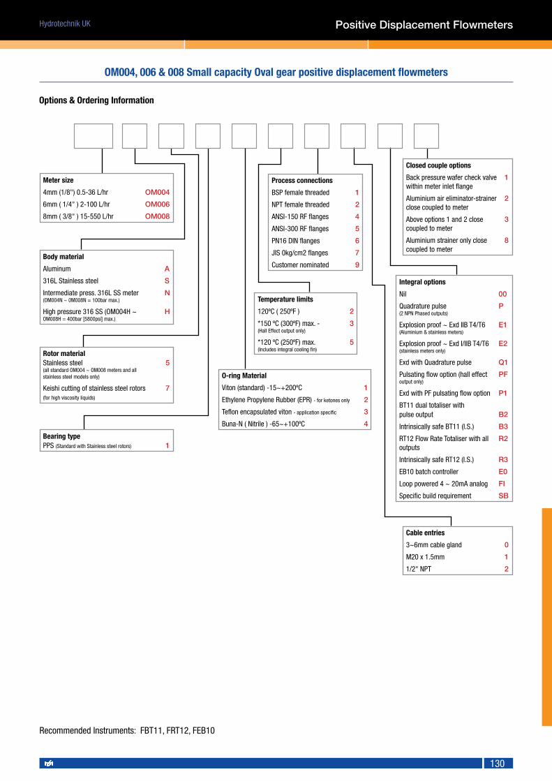
Hydrotechnik UK
130
Options & Ordering Information
Meter size
4mm (1/8") 0.5-36 L/hr OM004
6mm ( 1/4" ) 2-100 L/hr OM006
8mm ( 3/8" ) 15-550 L/hr OM008
Closed couple options
Back pressure wafer check valve 1within meter inlet flange
Aluminium air eliminator-strainer 2close coupled to meter
Above options 1 and 2 close 3coupled to meter
Aluminium strainer only close 8coupled to meter
Cable entries
3~6mm cable gland 0
M20 x 1.5mm 1
1/2" NPT 2
Bearing typePPS (Standard with Stainless steel rotors) 1
O-ring Material
Viton (standard) -15~+200ºC 1
Ethylene Propylene Rubber (EPR) - for ketones only 2
Teflon encapsulated viton - application specific 3
Buna-N ( Nitrile ) -65~+100ºC 4
Process connections
BSP female threaded 1
NPT female threaded 2
ANSI-150 RF flanges 4
ANSI-300 RF flanges 5
PN16 DIN flanges 6
JIS 0kg/cm2 flanges 7
Customer nominated 9
Integral options
Nil 00
Quadrature pulse P(2 NPN Phased outputs)
Explosion proof ~ Exd IIB T4/T6 E1 (Aluminium & stainless meters)
Explosion proof ~ Exd I/IIB T4/T6 E2 (stainless meters only)
Exd with Quadrature pulse Q1
Pulsating flow option (hall effect PFoutput only)
Exd with PF pulsating flow option P1
BT11 dual totaliser with pulse output B2
Intrinsically safe BT11 (I.S.) B3
RT12 Flow Rate Totaliser with all R2outputs
Intrinsically safe RT12 (I.S.) R3
EB10 batch controller E0
Loop powered 4 ~ 20mA analog FI
Specific build requirement SB
Body material
Aluminum A
316L Stainless steel S
Intermediate press. 316L SS meter N(OM004N ~ 0M008N = 100bar max.)
High pressure 316 SS (OM004H ~ HOM008H = 400bar [5800psi] max.)
Rotor materialStainless steel 5(all standard OM004 ~ OM008 meters and all stainless steel models only)
Keishi cutting of stainless steel rotors 7(for high viscosity liquids)
Temperature limits
120ºC ( 250ºF ) 2
*150 ºC (300ºF) max. - 3(Hall Effect output only)
*120 ºC (250ºF) max. 5(Includes integral cooling fin)
Positive Displacement Flowmeters
OM004, 006 & 008 Small capacity Oval gear positive displacement flowmeters
Recommended Instruments: FBT11, FRT12, FEB10

Hydrotechnik UK
131
Model prefix OM015 OM025 OM040 OM050/50E
Nominal size (inches) 15mm (1/2”) 25mm (1”) 40mm (11/2”) 50mm (2”)
* Flow range (litres / min) 1 ~ 40 10 ~ 150 15 ~ 250 30 ~ 450 /35 ~ 580
Accuracy @ 3cp ± 0.5% of reading ( ± 0.2% with optional RT12 )
Repeatability typically ± 0.03%
Temperature range -20ºC ~ +120ºC ( -4ºF ~ +250ºF )
Maximum pressure (threaded meters) bar (PSI)
Aluminium 70 70 30 20
316L stainless 70 70 30 38
interm. pressure stainless OM015, OM025 - 100 bar OM040 - 50 bar OM050 - 80 bar
high pressure stainless OM015, OM025, OM040 - 400 bar OM050 - 300 bar
Protection class IP66/67 (NEMA4X), optional Exd IIB T6 or I.S.
Recommended filtering 150 microns ( 100 mesh ) minimum
Electrical - for pulse meters (see also optional outputs)
Output pulse resolution pulses / litre ( pulses / US gallon ) - nominal
Reed switch 84 27 14 6.5 (4.7) E
Hall effect 168 107 ( 405 ) 56 26 (19) E
Quadrature Hall option 168 54.5 ( 203 ) 28.3 ( 100 ) 13 (9.5) E
Reed switch output 30Vdc x 200mA max. (max. temp. shock 10ºC (50ºF) / min)
Hall effect output (NPN) 3 wire open collector, 5~24Vdc max., 20mA max
Optional functions
Display flowrate, total (accumulative & resettable)
Preset batching 1 & 2 stage high speed batch control
IP65 3 digit reset mechanical totaliser 999.9 ltr/gal 9999 litres or gallons
IP65 4 digit reset mechanical totaliser 9999.9 ltr/gal 99999 litres or gallons
Mechanical Accum. totaliser capacities M1 & M2 (6 digit), M3 & M4 (8 digit)
Optional outputs
Flow 4 ~ 20mA, high & low flow rate alarms
Pulse scaled pulse (programmable) , pulse amplifier
Flomec medium capacity flowmeters provide precise volumetric flow measurement of clean liquids found in a broad range of industries including automotive, aviation, mining, power, chemical, pharmaceutical, food, paint & petroleum. Applications include the distribution of fuels, fuel oils, lubricants, alcohols, solvents, blending of bio & ethanol fuels, metering of chemicals, grease, adhesives, ink, insecticides & non-conductive liquids either pumped or gravity fed.
Dim. A A A A A A B B B B B B B B
Connection type
OM015A OM025A OM025S OM040 OM050A OM050S fitted with... OM015A OM015S OM025A OM025S OM040A OM040S OM050A OM050S
A.N.S.I. 150 - 198 237 252 272 277 RT12/EB register 154 148 168 165 203 194 218 268
DIN 16 - 198 237 252 272 277 BT register 145 139 160 157 195 196 210 260
JIS 10K - 198 237 252 266 277 RT20 register 157 151 171 168 206 197 221 271
B.S.P 110 137 176 188 212 212 cover 106 100 120 117 155 146 170 220
N.P.T 110 137 176 188 212 212 mech register 178 176 188 214 227 222 237 286
Positive Displacement Flowmeters
OM015, 025, 040 & 050 Medium capacity Oval gear positive displacement flowmeters
Technical Information• Industrial construction for rugged environments• ATEX EEx designs• Pressure rating up to 400 Bar• Optional directly mounted display
OM040 threaded unit with pulse output
OM025 threaded unit with BT11 LCD totalising display
OM050 flanged unit with 4 / 8 digit mechanical register
Dimensional Information
* Maximum flow on fuels may be maintained for intermittent periods of refuelling.* Maximum flow is to be reduced as viscosity increases, max. pressure drop 100Kpa (15psi)

Hydrotechnik UK
132
Options & Ordering Information
Meter size
15mm (1/2") 1-40 L/min OM015
25mm (1") 10-150 L/min OM025
40mm (11/2") 15-250 L/min OM040
50mm (2") 30-450 L/min OM050
50mm (2" high flow) OM050E
Closed couple options
Back pressure wafer check valve 1within meter inlet flange
Aluminium air eliminator-strainer 2close coupled to meter
Above options 1 and 2 close 3coupled to meter
Aluminium strainer only close 8coupled to meter
Cable entries
3~6mm cable gland 0
M20 x 1.5mm 1
1/2" NPT 2
Bearing typePPS 1(Standard with Stainlesssteel rotors)
Hardened steel roller bearings 4(aluminium rotors only)
O-ring Material
Viton (standard) -15~+200ºC 1
Ethylene Propylene Rubber (EPR)- for ketones only 2
Teflon encapsulated viton - application specific 3
Buna-N ( Nitrile ) -65~+100ºC 4
Process connections
BSP female threaded 1
NPT female threaded 2
*Tri-clamp hygienic ferrules 3
ANSI-150 RF flanges 4
ANSI-300 RF flanges 5
PN16 DIN flanges 6
Jis 10kg/cm2 flanges 7
Customer nominated 9 Integral options
Nil 00
Quadrature pulse QP(2 NPN Phased outputs)
Explosion proof ~ Exd IIB T4/T6 E1 (Aluminium & stainless meters)
Explosion proof ~ Exd I/IIB T4/T6 E2 (stainless meters only)
Exd with Quadrature pulse Q1
Pulsating flow option PF(hall effect output only)
Exd with PF pulsating flow option P1
BT11 dual totaliser with pulse output B2
Intrinsically safe BT11 (I.S.) B3
RT12 Flow Rate Totaliser with all R2outputs
Intrinsically safe RT12 (I.S.) R3
EB10 batch controller E0
Loop powered 4 ~ 20mA analog FI
Specific build requirement SB
Body material
Aluminum A
Intermediate pressure aluminium M(Only OM025 =138 Bar [2000psi] max.)
316L Stainless steel S
Intermediate press. 316L SS meter N(OM015N ~ 025N = 100bar, OM040N= 50bar, OM050N = 80bar max.)
High pressure 316 SS H(OM025H ~040H = 400bar [5580psi] max. OM050H = 300bar max.)
Rotor material
Aluminum (aluminium meters only). Only 4available in models OM015 and larger.
Stainless steel rotors fitted to aluminium 5meters (Select bearing type). Only available in models OM015 to OM050
Keishi cutting of aluminium rotors 6 (for high viscosity liquids)
Keishi cutting of stainless steel rotors 7(for high viscosity liquids)
Temperature limits
120ºC 2
*150 ºC max. 3(Hall Effect output only)
*120 ºC (250ºF) max. 5(Includes integral cooling fin)
*80 ºC (180ºF) max. 8(For TF-PPS rotors and/or with BT,RT,EB options)
Positive Displacement Flowmeters
OM015, 025, 040 & 050 Medium capacity Oval gear positive displacement flowmeters
Recommended Instruments: FBT11, FRT12, FEB10
(High Flow version only in Aluminium)

Hydrotechnik UK
133
Flomec large capacity flowmeters are suited for receipt verification, loading, unloading & distribution management at petroleum depots, mine sites, marine & aviation facilities. Common transfer applications involve fuels, oils, solvents, alcohols along with the blending of bio & ethanol fuels either pumped or gravity fed. The meters are compact & light weight in construction, important benefits when used in mobile installations or within confined spaces.
Model prefix OM080 OM80E OM100 OM100E
Nominal size ( inches ) 80mm ( 3” ) 80mm ( 3” ) 100mm ( 4” ) 100mm ( 4” )
* Flow range ( litres / min ) 35 ~ 750 50 ~ 1000 75 ~ 1500 150 ~ 2500
Accuracy @ 3cp ± 0.25% of reading
Repeatability typically ± 0.03%
Temperature range -20ºC ~ +120ºC
Maximum pressure bar ( PSI )
Aluminium 12 ( 180 ) 12 ( 180 ) 10 ( 150 ) 10 ( 150 )
Ductile iron 12 ( 180 ) - 10 ( 150 ) -
high pressure stainless on request
Protection class IP66/67 (NEMA4X), optional Exd IIB T6 or I.S.
Recommended filtering 350 microns ( 40 mesh ) minimum
Electrical - for pulse meters (see also optional outputs)
Output pulse resolution pulses / litre ( pulses / US gallon ) - nominal
Reed switch 2.65 1.55 1.1 0.56
Hall effect 10.65 6.2 4.4 2.24
Quadrature Hall option 5.33 3.1 2.2 1.12
Reed switch output 30Vdc x 200mA max. (max. temp. shock 10ºC (50ºF) / min)
Hall effect output (NPN) 3 wire open collector, 5~24Vdc max. 20mA max.
Optional functions
Display flowrate, total (accumulative & resettable)
Preset batching 1 & 2 stage high speed batch control
Optional mechanical registers ( IP65 )
3 digit reset totaliser 9999 litres or gallons ( 6 digit accumulative )
4 digit reset totaliser 99999 litres or gallons ( 8 digit accumulative )
Optional outputs
Flow 4 ~ 20mA, high & low flow rate alarms
Pulse scaled pulse (programmable), pulse amplifier
Dim. A A A A B B B B B
Connection type OM080 OM080E OM100 OM100E fitted with... OM080-A OM080S OM080E OM100 OM100E
A.N.S.I. 150 354 382 388 414 RT12/EB register 260 257 277 322 399
DIN 16 354 382 388 414 BT register 252 249 269 314 391
JIS 10K 354 382 388 414 RT20 register 264 260 281 326 403
B.S.P 266 294 294 320 cover 213 206 229 274 352
N.P.T 266 294 294 320 mech.register 270 N/A 288 333 416
* Maximum flow on fuels may be maintained for intermittent periods of refuelling.* Max. flow is to be reduced as viscosity increases, max. press. drop 100Kpa (15psi)
OM080 & OM100 Large capacity Oval gear positive displacement flowmeters
Positive Displacement Flowmeters
• Industrial construction for rugged environments• ATEX EEx designs• Flow rates up to 2500 l/min• Optional directly mounted display
OM100 flanged unit with pulse output
OM080 threaded unit with BT11 LCD totalising display
OM080 flanged unit with 4 / 8 digit mechanical register
Dimensional Information
Technical Information

Hydrotechnik UK
134
Options & Ordering Information
Meter size
80mm (3") 35-750 L/min OM080
80mm (3" high flow) OM080E50-1000 L/min
100mm (4") 75-1500 L/min OM100
100mm (4" high flow) OM100E150-2500 L/min
Closed couple options
Back pressure wafer check valve 1within meter inlet flange Aluminium air eliminator-strainer 2close coupled to meter
Above options 1 and 2 close 3coupled to meter
Aluminium strainer only close 8coupled to meter
Cable entries
3~6mm cable gland 0
M20 x 1.5mm 1
1/2" NPT 2
O-ring Material
Viton (standard) -15~+200ºC 1
Ethylene Propylene Rubber (EPR)- for ketones only 2
Teflon encapsulated viton - application specific 3
Buna-N ( Nitrile ) -65~+100ºC 4
Process connections
BSP female threaded 1
NPT female threaded 2
*Tri-clamp hygienic ferrules 3
ANSI-150 RF flanges 4
ANSI-300 RF flanges 5
PN16 DIN flanges 6
Jis 10kg/cm2 flanges 7
Customer nominated 9 Integral options
Nil 00
Quadrature pulse QP(2 NPN Phased outputs)
Explosion proof ~ Exd IIB T4/T6 E1 (Aluminium & stainless meters)
Explosion proof ~ Exd I/IIB T4/T6 E2 (stainless meters only)
Exd with Quadrature pulse Q1
Pulsating flow option PF(hall effect output only)
Exd with PF pulsating flow option P1
BT11 dual totaliser with pulse output B2
Intrinsically safe BT11 (I.S.) B3
RT12 Flow Rate Totaliser with all R2outputs
Intrinsically safe RT12 (I.S.) R3
EB10 batch controller E0
Loop powered 4 ~ 20mA analog FI
Specific build requirement SB
Body material
Aluminum A
316L Stainless steel S
Ductile iron (Consult factory) D
Rotor material
Aluminum 4(aluminium meters only)
Stainless steel 5(all stainless steel models only)
Keishi cutting of aluminium rotors 6(for high viscosity liquids)
Keishi cutting of stainless steel rotors 7(for high viscosity liquids)
Positive Displacement Flowmeters
OM080 & OM100 Large capacity Oval gear positive displacement flowmeters
Bearing type
PPS 1(Standard with Stainless steel rotors)
Hardened steel roller bearings 4(aluminium rotors only)
Recommended Instruments: FBT11, FRT12, FEB10
(High Flow version only in Aluminium)
Temperature limits
120ºC 2
*150 ºC max. 3(Hall Effect output only)
*120 ºC max. 5(Includes integral cooling fin)
*80 ºC max. 8(For TF-PPS rotors and/or with BT,RT,EB options)

Hydrotechnik UK
135
Model Size Size A L H W D (mm)
ST006 DN8 1/4" 10.0 65.0 51.0 2.0 200 mesh
ST008 DN10 3/8" 12.0 65.0 51.0 2.0 200 mesh
ST015 DN15 1/2" 15.0 65.0 51.0 2.0 100 mesh
ST025 DN25 1" 25.0 90.0 72.0 2.0 100 mesh
ST040 DN40 11/2" 40.0 120.0 87.0 2.0 100 mesh
ST050 DN50 2" 50.0 140.0 103.0 2.0 100 mesh
No Part number Material
1 Body CF8M
2 Screen SS316
3 Gasket PTEF
4 Bonnet CF8M
5 O-ring Viton
6 Plug CF8M
Technical InformationBody: Stainless steelScreen: DN8 to 10 = 200 mesh (74µm) DN15 to 50 = 100 mesh (149µm)Packing: PTFEWorkingPressure: 55 BarEndConnections: Threaded Female
• Economic filtration solution to prevent costly down time• Simple way to protect positive displacement flowmeters
Y Strainers for Positive displacement meters
Positive Displacement Flowmeters
Dimensional Information, Options & Ordering Information

Hydrotechnik UK
136
Meters of the Flowal® series are positive displacement flowmeters and due to their modular design they can be adapted to a wide field of applications. The Flowal® Oval Wheel Meters are of a specially robust and simple design and impressively user friendly. The innovative concept is the result of merging more than 70 years of experience with the latest technologies.
The unique profile of the gears offers superior performance and the ability to maintain linearity and low flow performance even on low viscosity or water like liquids.
Size A B Connection
OR-015 78 100 G1/4" BSP
OR-06 78 105 G1/4" BSP
OR-1 78 115 G1/2" BSP
OR-2 99 115 G3/4" BSP
OR-5 112 119 G1" BSP
OR-10 112 146 G1" BSP
Model Code Flow Range (l/min)
OR-015 0.03-1 PVDF/PEEK only
OR-06 0.2-5
OR-1 0.3-10
OR-2 1-30
OR-5 2-60 PP/PEEK only
OR-10 3-120 PVDF/PEEK only
Technical InformationAccuracy* <± 1% of the measured value without calibration <± 0,5% of the measured value with calibrationRepeatability 0,1% of the measured valueMaxworkingpressure 6 bar (PVDF), 10 bar (PP)Operating temperature -10°C to +80 °CAmbient temperature -10 °C to +60°C (blind design)Process connection G1/4" BSP (OR015 and 06), G1/2" BSP (OR-1) G3/4” BSP (OR-2), G1" BSP (OR-5 and 10)Electrical connection supply according to NAMUR or 10 – 24VDCOutputs pulse (open collector NPN/PNP or NAMUR)Materials Measuring chamber PP/PVDF Oval wheels PEEKDegree of protection IP 67 (blind design)
Recommended Instruments: FBT11, FRT12, FEB10
Flowal series Oval gear positive displacement flowmeters in PP & PVDF
Positive Displacement Flowmeters
• Proven design from the inventors of the Oval gear• Chemically resistant PVDF and PP design• Flow rates down to 30 mL/Min• Sealed to IP67
Flowal in PVDF
Flowal in Polypropylene
Dimensional Information
Options & Ordering Information

Hydrotechnik UK
137
The OAP series of oval wheel meters has the following special design characteristicsThe casing and the measurement chamber are separate components. The measurement chamber is pressure relived, free from stresses and is installed in the meter casing. The axles for the oval wheels are placed in the measurement chamber bottom and for meter sizes ≥ DN 65 they are also supported in the measurement chamber cover.
A permanent magnetic coupling is the basis for the transmission of the rotational movement from the measurement area to the dry area. Hard graphite sleeve bearings insure the proper running of both oval wheel with high operational safety and long service life. Units 50 years old are still known to be in operation.
Oval wheel meters of the OAP series can, as for all other oval wheel meters, be adjusted to almost all operating conditions by means of various combinations of materials for the casing, measurement chamber, oval wheels and bearings.The OAP series of oval wheel meters is also produced with a heating jacket. This is given the series designation of OUAP.
• Proven design from the inventors of the oval gear flowmeter• Sizes up to 16” (DN400)• Long service life• Custody transfer, meter proving and tanker loading applications
Recommended Instruments: FBT11, FRT12, FEB10
OAP series Large diameter Oval gear positive displacement flowmeters
Positive Displacement Flowmeters
Technical InformationNominal pressure PN 16 to PN 100, at temperatures over 120°C pay attention to pressure reduction!
120°C bis 200°C permissible operating pressure=0,8xPN
200°C bis 250°C permissible operating pressure=0,7xPN
250°C bis 290°C permissible operating pressure=0,6xPN
Measuring accuracy ± 0.1% to ± 0.3% of the measured value. This depends on the measurement range and material being measured or in accordance with the particular calibration regulations.
Media temperature Depending on the model, -140°C to +290°C.
Materials Cast iron, cast steel, stainless steel, aluminium, brass/bronze
Approvals Approved by the Bureau of Standards in Germany and many other countries (EC-Approvals).
Accessories The following accessories are available for the OAP oval wheel meters:
• Mechanical single indicator E, indicator cannot be reset
• Mechanical double indicator D, indicator can be reset
• Mechanical roller counter M5, which can be reset
• Mechanical roller counter with printer M5B, can be reset
• Resettable mechanical roller counter with quantity setting device M5V
• Resettable mechanical roller counter with printer and quantity setting device M5BV
• Universal Smart Transmitter (UST) with HART communication
• Strainer
• Centrifugal gas separator, specially for measuring systems requiring calibration < 20 mPas
• Temperature compensation / Temperature extension

Hydrotechnik UK
138
Type DN FlowrateQmaxl/min
Ranges at Viscosity
<0,3 mPa*s 0,3-1,5 mPa*s 1,5-150 mPa*s upto 350 mPa*s upto 1000 mPa*s up to 3000 mPa*s
l/min m3/h l/min m3/h l/min m3/h l/min m3/h l/min m3/h l/min m3/h
OaP5251"
50
Min 8 0,5 5 0,3 5 0,3 2,5 0,15 1,25 0,075 0,45 0,027
Max 40 2,5 50 3 50 3
25 1,5 12,5 0,75 4,5 0,72continuous16 1,0
33 2 45 2,7
Batch Processing 45 2,7 50 3
OaP10251"
100
Min 16 1,0 10 0,6 10 0.6 7 0,42 3,5 0,20 1,2 0,072
Max 80 5,0 100 6 100 6
70 4,2 35 2,0 12 0,72continuous33 2,0
66 4 90 5,4
Batch Processing 90 5,4 100 6
OaP50502"
300
Min 50 3,0 30 1,8 30 1,8 18 1,08 9,0 0,54 3 0,18
Max 250 15 300 18 300 18
180 10,8 90 5,4 30 1,8continuous100 6
200 12 270 16,2
Batch Processing 270 16,2 300 18
OaP12565
21/2"700
Min 100 6 70 4,2 70 4,2 60 3,6 40 2,4 15 0,9
Max 500 30 700 42 700 42
600 36 400 24 150 9continuous200 12
420 25,2 525 31,5
Batch Processing 560 33,6 630 37,8
OaP250803"
1200
Min 200 12 120 7,2 120 7,2 100 6 60 3,6 30 1,8
Max 1000 60 1200 72 1200 72
1000 60 600 36 300 18continuous 400 24 720 43,2 1000 60
Batch Processing 500 30 960 57,6 1200 72
OaP6001004"
3000
Min 400 24 250 15 250 15 200 12 150 9 75 4,5
Max 2000 120 3000 180 3000 180
2500 150 1500 90 750 45continuous 800 48 1650 100 2500 150
Batch Processing 1000 60 3000 180 3000 180
OaP1200
1200.1
1508"
5000
Min 800 48 500 30 500 30 400 24 250 15 120 7,2
Max 4000 240 5000 300 5000 300
4000 240 2500 150 1200 72continuous 1600 96 2500 150 3500 200
Batch Processing 2000 120 4000 240 4000 240
OaP2000
2008"
8000
Min 1300 80 800 48 800 48 660 40 400 24 200 12
Max 6500 400 8000 480 8000 480
6600 400 4000 240 2000 120continuous2600 160
4000 240 5500 320
Batch Processing 5000 300 6600 400
OaP3200
30012"
12000
Min 2000 120 1200 72 1200 72 1000 60 600 36 300 18
Max 10000 600 12000 720 12000 720
10000 600 6000 360 3000 180continuous4000 240
6000 360 8000 480
Batch Processing 8000 480 10000 600
OaP4000
40016"
20000
Min 3200 200 2000 120 2000 120 1500 90 1000 60 400 24
Max 16000 1000 20000 1200 20000 1200
15000 900 10000 600 4000 240continuous6600 400 10000 600
13500 800
Batch Processing 15000 900
OAP series Large diameter Oval gear positive displacement flowmeters
Positive Displacement Flowmeters
Options & Ordering Information

Hydrotechnik UK
139
The ZHA series represents a positive displacement meter that is affordable and accurate. One primary feature is the ability to maintain consistent accuracy despite changing viscosity conditions. This reliability, coupled with a large turndown range, offers an affordable replacement for older turbine technology. The meter’s solid construction and excellent dynamic response are well suited to the measurements of oil, grease, fuel, solvents, polyeurethanes, brake fluid, skydrol as well as other non abrasive lubricating fluids. Since there is no need for straight run piping upstream or downstream of the flow meter, the ZHA flow meters are simple to use and to install. The meters produce good resolution and high accuracy at low flow rates. Flow may be bidirectional without damage to internal parts. Non-intrusive sensors, panel displays and electronic modules can be added to complete this superior value package.
Model Code Connection thread (female)
Measuring rangeltr/min
K-factorpulses/ltr
Pressurebar
Weightkg
ZHA01/2.KL.D 1/4" BSP or NPT 0.02 to 3 28,000 350 0.30
ZHA02.KL.D 1/4" BSP or NPT 0.1 to 7 8,400 350 0.38
ZHA03.KL.D 1/2" BSP or NPT 0.5 to 25 3,480 350 0.50
ZHA04.KL.D 3/4" BSP or NPT 0.5 to 70 950 350 2.25
ZHA05.KL.D 1" BSP or NPT 5 to 150 268 350 12.7
ZHA06.KL.D 1" BSP or NPT 20 to 500 106 350 16.8
VHE Single Hall Effect Sensor VHD Dual Hall Effect Sensor
Supply Voltage 12 to 24 VDC, max. 10 mA 12 to 24 VDC, max. 10 mA
Frequency range 1 up to 3,000 Hz 1 up to 3,000 Hz
Output Square wave signalSquare wave signal
double measuring frequency and reverse-flow detection
Output impedance approx. 470 Ω approx. 470 Ω
Temperature range 0 up to +70°C 0 up to +70°C
Electrical connection
5-pin plug1 = Supply voltage2 = Output signal
3 = 0V/GND4 = nc5 = nc
5-pin plug1 = Supply voltage2 = Output signal 1
3 = 0V/GND4 = Output signal 2
5 = nc
Positive Displacement Flowmeters
MaterialsHousing: high-strength aluminium ALCuMgPbGears: stainless steel as per DIN 1.4122/AISI 303 or 1.4460/AISI 329 (special)Shafts, bearings: stainless steelO-ring: viton or teflon
• Economic alternative to Stainless Steel designs• Pressure rating up to 350 Bar• Up to 28,000 pulses per Litre• Bi-directional flow
Recommended Instruments: FBT11, FRT12, FEB10
ZHA series Aluminium circular gear positive displacement flowmeter
Sensor Output Information
Options & Ordering Information
Ordering example
ZHA03.KL.D.VHE ZHA aluminium gear flow meter 0.5 to 25 L/min. Ball bearings (KL) with VHE single hall effect amplified frequency output sensor

Hydrotechnik UK
140
ZHM gear flow meters are used for the precise flow measurements of various fluids with a huge range of viscosities from 5 up to 25,000mm2/s. Providing high accuracy (±0.5%), high pressure ratings (up to 1000 Bar on request) and wide measuring range (0.005 up to 1000 l/min) make this a great meter for demanding applications.
Signal pick up options• VTE*/P: carrier-frequency amplifier with single pickup, for fluids up to +150oC
• VTE*/P Ex: carrier-frequency amplifier with single pickup, for fluids up to +150oC. ATEX certified.
• VTM: local display unit with integral frequency-and analogue output, for fluids up to +150oC
• TD*: carrier-frequency amplifier with twin pickup, for fluids up to +80oC
• VTQ: quadruple carrier-frequency pickup an amplifier with integral divider, for fluids up to +80oC
• FOP: fibre-optical amplifer for electrostatic environment, fluids up to +60oC
• IF*/VIEG: inductive pickup and amplifer for fluids up to +180oC
• IF*/VIEG Ex: inductive pickup and amplifer for fluids up to +180oC. ATEX certified.
• HE, HD: halleffect amplifer for fluids up to +80oC
ZHM type Connection thread (female)
Measuring range K-factor (pulses/ltr) Pressure Frequency range
ltr/min Single pickup Twin pickup bar Hz, single pickup
ZHM01 1/4" BSP 0.005 to 1 41,000 82,000 630 3.4 to 683
ZHM01/1* 1/4" BSP 0.005 to 2 26,500 53,000 630 2.2 to 883
ZHM01/2* 1/4" BSP 0.02 to 3 14,000 28,000 630 4.6 to 700
ZHM02/1* 1/4" BSP 0.05 to 2 8,200 16,400 630 6.8 to 273
ZHM02* 1/4" BSP 0.1 to 7 4,200 8,400 630 7 to 490
ZHM03 3/8" BSP 0.5 to 25 1,740 3,480 630 14 to 725
ZHM04 1/2" BSP 0.5 to 70 475 950 630 4 to 554
ZHM05 3/4" BSP 5 to 150 134 268 400 11 to 335
ZHM06/1 SAE 1.1/4" flange 5 to 250 106 212 400 8.8 to 442
ZHM06 SAE 1.1/2" flange 20 to 500 53 106 400 18 to 442
ZHM07 SAE 1.1/2" flange 50 to 1,000 24 48 400 20 to 400
Ordering examples
ZHM02KL.VTEL/P ZHM stainless steel gear flow meter 0.1 to 7 L/min. Ball bearings (KL) with carrier-frequency amplifier with single pickup, for fluids up to +150oC
ZHM05ST.IF/ViEG ZHM stainless steel gear flow meter 5 to 150 L/min. Hard metal bearings (ST) with inductive pickup and amplifer for fluids up to +180oC
Positive Displacement Flowmeters
MaterialsHousing: standard: stainless steel as per DIN 1.4305 / AISI 303Special: DIN 1.4404 / AISI 316 L or 1.4571 / AISI 316 TiGears: stainless steel as per DIN1.4122 / AISI 303, special: DIN 1.4460 / AISI 329Shafts, bearings: tungsten carbide, ball on requestSeals: Viton, NBR, EPDM (for brake fluids) or Teflon
Recommended Instruments: FBT11, FRT12, FEB10
• Pressure rating up to 100 Bar• High resolution up to 82,000 Pulses per Litre• Flow rates down to 5 mL/Min• ATEX EEx design
ZHM series Stainless steel circular gear positive displacement flowmeter
Options & Ordering Information
* Replace with sensor code for short or long pickup depending on meter size and fluid temperature.

Hydrotechnik UK
141
Positive displacement Flowmeter
• Huge 1000:1 measuring range• Cast iron and Stainless Steel versions• High temperature option to 210°C• Flow rates down to 2ml/min• ATEX EEx design
Technical InformationAccuracy ± 0.3 % of measured value at viscosity > 20 cSt (< 20 cSt reduced accuracy)Repeatability ± 0.05 % under same operating conditionsMaterials Body Bearings seals Cast iron Ball / Plain / Plain FPM (Standard) Stainless Steel 1.4305 (Copper-free) depend on liquid NBR, PTFE, EPDMMax. operating pressures cast iron stainless steel 315 bar 450 barMedium temperature Standard –40 ≤ ... 120° C Ex-design –20 ≤ ... 100° C High temperature –40 ≤ ... 210° CViscosity Ranges 1...100 000 cStMounting positions unrestricted, on subplate with side or bottom connectionsFiltering for ball bearing type VS 0.02/0.04/0.1 10 µm VS 0.2/0.4 20 µm VS 1/2 50 µm VS 4 50 µmNoise level max. 72 dB(A)Preamplifier 10 to 28 Volt (DC)
VS series Cast iron or stainless steel circular gear positive displacement flowmeter
VS positive displacement flow meters are volume rate measuring sensors based on the meshing gear principle and are designed for use with liquids up to 100,00 cSt. Flow ranges are available from 0.002 l/min up to 525 l/min. Most ranges are capable of a massive 1000:1 measuring range making this a unique option. Cast iron or Stainless Steel bodied versions are available to help suit your application or budget.
Model Code BSP or NPT female threaded connections
(via subplate)
Measuring rangeltr/min (at 21c cSt)
K-factorpulses/ltr
Weight (kg)C.I / St.St
VS0.02 1/4", 3/8" or 1/2" 0.002 to 2 50,000 2.8 / 3.4
VS0.04 1/4", 3/8" or 1/2" 0.004 to 4 25,000 2.8 / 3.4
VS0.1 1/4", 3/8" or 1/2" 0.01 to 10 10,000 2.8 / 3.4
VS0.2 1/4", 3/8" or 1/2" 0.02 to 18 5,000 3.0 / 3.7
VS0.4 1/2" or 3/4" 0.03 to 40 2,500 4.0 / 5.0
VS1 1/2", 3/4" or 1" 0.05 to 80 1,000 5.3 / 6.8
VS2 1/2", 3/4" or 1" 0.1 to 120 500 6.7 / 8.4
VS4 1.1/4" or 1.1/2" 1 to 250 250 14.7 / 18.4
VS10 1.1/2" 1.5 to 525 300 on request
Options & Ordering Information
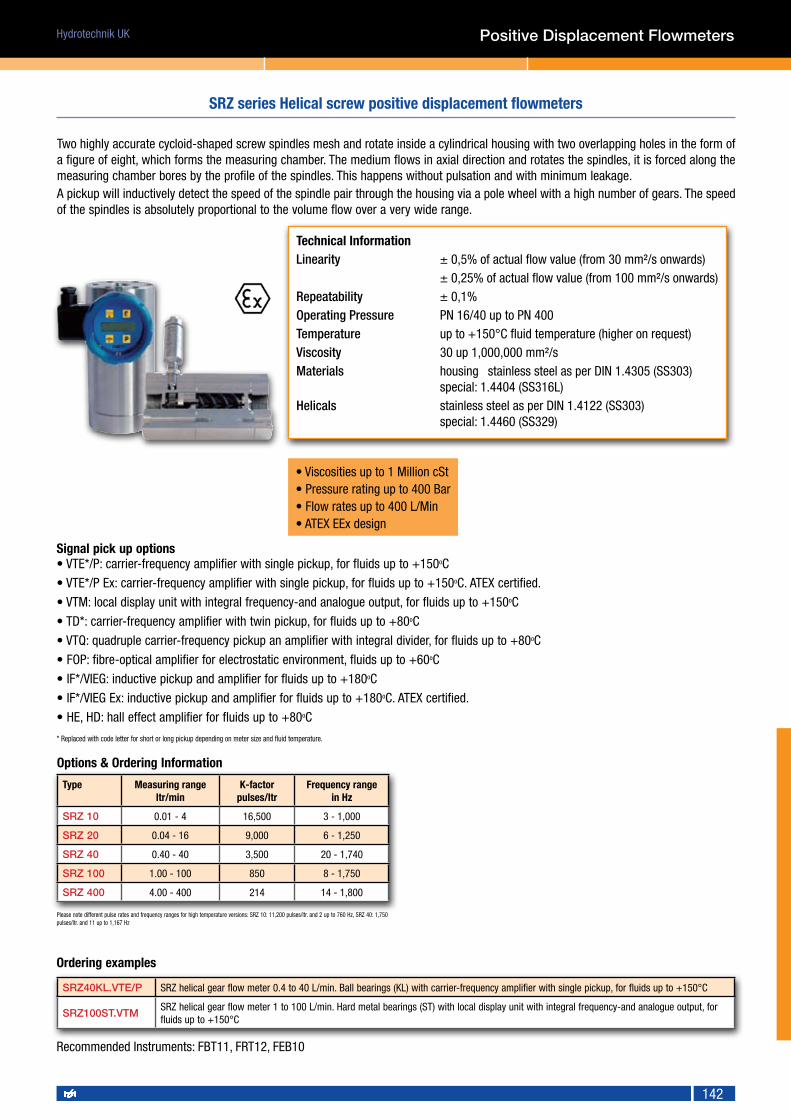
Hydrotechnik UK
142
Two highly accurate cycloid-shaped screw spindles mesh and rotate inside a cylindrical housing with two overlapping holes in the form of a figure of eight, which forms the measuring chamber. The medium flows in axial direction and rotates the spindles, it is forced along the measuring chamber bores by the profile of the spindles. This happens without pulsation and with minimum leakage.A pickup will inductively detect the speed of the spindle pair through the housing via a pole wheel with a high number of gears. The speed of the spindles is absolutely proportional to the volume flow over a very wide range.
Signal pick up options• VTE*/P: carrier-frequency amplifier with single pickup, for fluids up to +150oC
• VTE*/P Ex: carrier-frequency amplifier with single pickup, for fluids up to +150oC. ATEX certified.
• VTM: local display unit with integral frequency-and analogue output, for fluids up to +150oC
• TD*: carrier-frequency amplifier with twin pickup, for fluids up to +80oC
• VTQ: quadruple carrier-frequency pickup an amplifier with integral divider, for fluids up to +80oC
• FOP: fibre-optical amplifier for electrostatic environment, fluids up to +60oC
• IF*/VIEG: inductive pickup and amplifier for fluids up to +180oC
• IF*/VIEG Ex: inductive pickup and amplifier for fluids up to +180oC. ATEX certified.
• HE, HD: hall effect amplifier for fluids up to +80oC
* Replaced with code letter for short or long pickup depending on meter size and fluid temperature.
Type Measuring rangeltr/min
K-factor pulses/ltr
Frequency rangein Hz
SRZ 10 0.01 - 4 16,500 3 - 1,000
SRZ 20 0.04 - 16 9,000 6 - 1,250
SRZ 40 0.40 - 40 3,500 20 - 1,740
SRZ 100 1.00 - 100 850 8 - 1,750
SRZ 400 4.00 - 400 214 14 - 1,800
Ordering examples
SRZ40KL.VTE/P SRZ helical gear flow meter 0.4 to 40 L/min. Ball bearings (KL) with carrier-frequency amplifier with single pickup, for fluids up to +150°C
SRZ100ST.VTMSRZ helical gear flow meter 1 to 100 L/min. Hard metal bearings (ST) with local display unit with integral frequency-and analogue output, for fluids up to +150°C
Please note different pulse rates and frequency ranges for high temperature versions: SRZ 10: 11,200 pulses/ltr. and 2 up to 760 Hz, SRZ 40: 1,750 pulses/ltr. and 11 up to 1,167 Hz
Technical Information Linearity ± 0,5% of actual flow value (from 30 mm²/s onwards) ± 0,25% of actual flow value (from 100 mm²/s onwards)Repeatability ± 0,1%Operating Pressure PN 16/40 up to PN 400Temperature up to +150°C fluid temperature (higher on request)Viscosity 30 up 1,000,000 mm²/s Materials housing stainless steel as per DIN 1.4305 (SS303) special: 1.4404 (SS316L) Helicals stainless steel as per DIN 1.4122 (SS303) special: 1.4460 (SS329)
• Viscosities up to 1 Million cSt• Pressure rating up to 400 Bar• Flow rates up to 400 L/Min• ATEX EEx design
Recommended Instruments: FBT11, FRT12, FEB10
SRZ series Helical screw positive displacement flowmeters
Positive Displacement Flowmeters
Options & Ordering Information

Hydrotechnik UK
143
Magnetic inductive flowmeters use Faraday’s principles to infer the velocity of a liquid passing through them. In effect the liquid becomes a moving conductor in a magnetic field the resultant emf (voltage) is proportional to the velocity of the liquid flow rate. For the liquid to be a conductor it must be conductive in nature, this type of flowmeter cannot be used for non-conductive fluids such as oils.
In-line magnetic inductive flowmeters use a non-conductive or lined section of pipe with electrodes in the side walls to sense the emf generated, the inductive coils are placed outside the pipe leaving nothing to restrict the flow. Insertion designs are also available which prove very cost effective for applications where absolute accuracy is not required.
These flowmeters have no moving parts and offer very little in the way of pressure loss. With a range of non-conductive liners and electrodes materials these device offer the ability to measure a wide range of liquids from water, through acids and bases to slurries and with their output being independent of viscosity even thick media can be measured without any need for correction.
Principle of operation
Magnetic Inductive flowmeters - principle of operation
Magnetic Inductive Flowmeters
Principle of Magnetic Inductive flow measurement
Water Chemicals
Media application guide
Hygienic
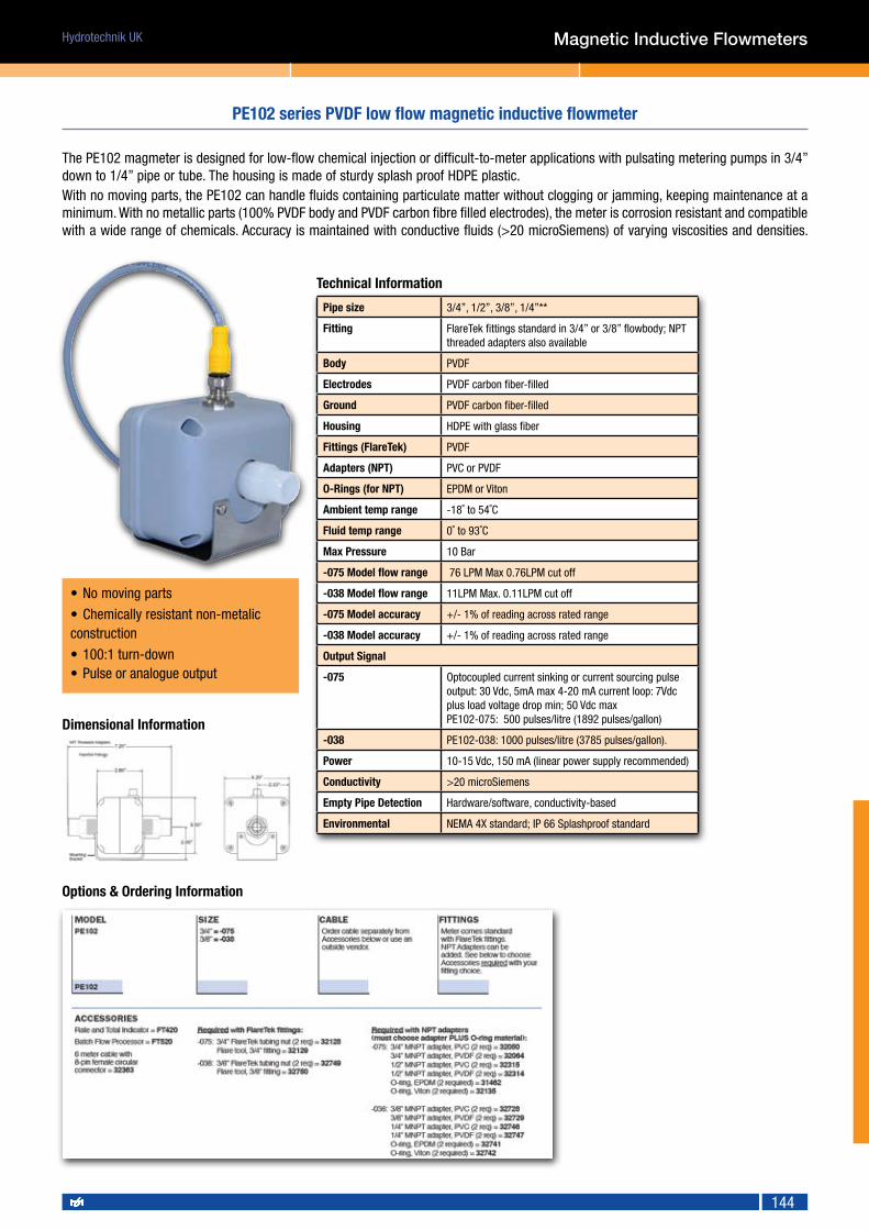
Hydrotechnik UK
144
The PE102 magmeter is designed for low-flow chemical injection or difficult-to-meter applications with pulsating metering pumps in 3/4” down to 1/4” pipe or tube. The housing is made of sturdy splash proof HDPE plastic.With no moving parts, the PE102 can handle fluids containing particulate matter without clogging or jamming, keeping maintenance at a minimum. With no metallic parts (100% PVDF body and PVDF carbon fibre filled electrodes), the meter is corrosion resistant and compatible with a wide range of chemicals. Accuracy is maintained with conductive fluids (>20 microSiemens) of varying viscosities and densities.
Pipe size 3/4”, 1/2”, 3/8”, 1/4”**
Fitting FlareTek fittings standard in 3/4” or 3/8” flowbody; NPT threaded adapters also available
Body PVDF
Electrodes PVDF carbon fiber-filled
Ground PVDF carbon fiber-filled
Housing HDPE with glass fiber
Fittings (FlareTek) PVDF
Adapters (NPT) PVC or PVDF
O-Rings (for NPT) EPDM or Viton
Ambient temp range -18˚ to 54˚C
Fluid temp range 0˚ to 93˚C
Max Pressure 10 Bar
-075 Model flow range 76 LPM Max 0.76LPM cut off
-038 Model flow range 11LPM Max. 0.11LPM cut off
-075 Model accuracy +/- 1% of reading across rated range
-038 Model accuracy +/- 1% of reading across rated range
Output Signal
-075 Optocoupled current sinking or current sourcing pulse output: 30 Vdc, 5mA max 4-20 mA current loop: 7Vdc plus load voltage drop min; 50 Vdc maxPE102-075: 500 pulses/litre (1892 pulses/gallon)
-038 PE102-038: 1000 pulses/litre (3785 pulses/gallon).
Power 10-15 Vdc, 150 mA (linear power supply recommended)
Conductivity >20 microSiemens
Empty Pipe Detection Hardware/software, conductivity-based
Environmental NEMA 4X standard; IP 66 Splashproof standard
Magnetic Inductive Flowmeters
PE102 series PVDF low flow magnetic inductive flowmeter
• No moving parts
• Chemically resistant non-metalic construction
• 100:1 turn-down• Pulse or analogue output
Technical Information
Dimensional Information
Options & Ordering Information

Hydrotechnik UK
145
The WMP is a full-bore, plastic-bodied electromagnetic flow meter designed for flow and usage monitoring applications in 1 and 2 inch pipe. The polypropylene flow tube offers corrosion resistance to a wide range of chemicals. Its light weight and easy to install or remove from the pipe for inspection.With no moving parts, the magmeter permits unobstructed flow, minimising flow disturbances and hence, straight pipe requirements. The WMP-Series can be used in piping configurations where there is little space between the meter and an elbow or valve. The WMP-Series, like other magmeters, are resistant to wear from sand and debris found in ground or surface water. Since there are no bearings or propeller to wear out, downtime and maintenance and repair costs are kept to a minimum. Because there are no mechanical parts in the flow stream, the meter tolerates high flows without damage.
• Battery powered option• Durable Polypropylene body• Ideal for irrigation applications• Display of flow rate and total
WMP series polypropylene magnetic inductive flowmeter
Pipe size 1 or 2 inch full port
Fittings 1 inch NPTF, 2 inch flange clamps with optional 2 inch NPTF fitting kit
Body Glass-filled polypropylene
Electrodes 316 stainless steel
Electronics Housing Diecast aluminium, powder-coated
Display Cover Polyethylene
Pressure 10.3 bar working pressure @ 21˚ C
Accuracy +/- 1% of reading across rated range
+/- 1% of reading across rated range
Minimum Flow 1 inch model: 0.145 liters per second2 inch model: 0.38 liters per second
Maximum Flow 1 inch model: 110 gallons per minute (6.94 liters per second) 2 inch model: 300 gallons per minute (18.9 liters per second)
Digits 6 (Flow Rate) 8 (Totaliser)
Units Gallons/Minute, Cubic Feet/Second,Cubic Feet/Minute, Liters/SecondLiters/Minute, Cubic Meters/Minute
Acre-Feet, Acre-Inch, Gallons,Gallons x 1000,Cubic Feet, Liters, Megaliters, Cubic Meters
Security Cross-drilled screws and tamper-evident seal (optional)
WMP101 10-30 Vdc @ 60 mA max (15 mA average)NOTE: Using an unregulated power supply >18 Vdc may damage the meter due to AC line input voltage fluctuation
WMP104 6 each AA alkaline cells, replaceable. Estimated life is 1-year with meter in typical use, or 3-years dry.2 each C lithium batteries, replaceable. Estimated life is 3-years with meter in typical use, or 10-years dry
Pulse Output Signal(WMP101 Only) Pulse Rate
Current sinking pulse, opto isolated, 24 Vdc at 10 mA max1 gal/pulse out, or 1 liter/pulse out, depending on unit selection. Pulse width of 10ms
High Frequency Output (WMP101 Only)
Optional, 30 PPG, pulse width 1.1 ms, min - max frequency, 3 - 150 hz
Empty Pipe Detection Hardware/software, conductivity-based
Conductivity >20 micro Siemens
Environmental NEMA 4X standard; -40˚ to 176˚ F (-40˚ to 80˚ C) storage
Electrical Connection (WMP101 Only)
5 pin male circular connector, mates to industry standard cable
Technical Information
Magnetic Inductive Flowmeters

Hydrotechnik UK
146
WMP series polypropylene magnetic inductive flowmeter
Dimensional Information
Options & Ordering Information
1" units 2" units
Magnetic Inductive Flowmeters

Hydrotechnik UK
147
EX80-Series insertion electromagnetic flowmeters are designed for use with conductive liquids in 1 to 12” pipe. A choice of materials (stainless steel, brass, and PVC) allows the meter to adapt to a range of temperature, pressure, and corrosive environments.The EX80 is highly suitable for difficult applications with changing viscosities and pulsating flows, such as air-driven diaphragm pumps. With no moving parts, these meters can be used in “dirty” applications where debris would foul a mechanical meter. Like all magmeters, when used in chemical injection applications, these meters should be installed upstream of the chemical line (or far enough downstream to allow complete mixing of fluids before the meter).
Pipe size 1" to 12"
Mechanical 316 SS/Brass/PVC
Electrodes Hastelloy
Housing Cast powder-coated aluminium
Electrode Cap PVDF (Kynar)
O-Ring EPDM standard (Viton optional)
Full Power 12 - 25 Vdc, 250 mA
Low Power 12 - 25 Vdc, 40 mA average with 250 mA peaks
Flow Rate 0.08 - 6.09 m/sec
Ambient Temp -17˚ to 72˚ C
Fluid Temp: Brass/SS 0˚ to 93˚ C
Fluid Temp: PVC 0˚ to 55˚ C @ 0 psi
Brass/SS msx pressure 13.8 bar
PVC max pressure 10 bar @ 75˚ F
Minimum Conductivity 20 micro Siemens/cm
Calibration Accuracy +/- 1% of full scale
Output Square wave pulse, opto isolated, 550 Hz @ 20 ft/sec
Empty Pipe Detection Software, defaults to zero flow
Regulatory CE Mark (Stainless Steel, Brass and Standard Power Only)
Options & Ordering Information
Meter style
1”-3” Pipe EX81
4”-10” Pipe EX82
12” Pipe EX83
Fitting type
PVC Tee with Solvent weld ends TP
Bronze Tee with NPT threads TB
StSt Tee with NPT threads TS
Bronze Braze on fitting WB
Carbon Steel Weld-on fitting WC
Stainless Steel Weld-on fitting WSMaterial
PVC P
Brass B
Stainless Steel S
Options
No option 00
Reverse flow Output 15
*Immersible (consult factory) 40
Low Power Version 50
Viton Seal 125
Flow range
2.6-185.2 L/Min (1”) 100
5.7-415.8 L/Min (1.1/2”) 150
10.2-740.9 L/Min (2”) 200
23.4-1,663 L/Min (3”) 300
41.6-2,960 L/Min (4”) 400
94.5-6,653 L/Min (6”) 600
162.5-11,831 L/Min (8”) 800
257-18,522 L/Min (10”) 1000
374-26,649 L/Min (12”) 1200
• No moving parts• Insertion design for pipe sizes up to 12”• 75:1 turn down 0.08-6 m/s• PVC, Brass and Stainless Steel designs
Recommended Instruments: FBT11, FRT12, FEB10
EX80 series insertion style magnetic inductive flowmeter
Dimensional Information
EX80 series - Brass EX80 series - Stainless Steel
EX80 series - PVC
Technical Information
Magnetic Inductive Flowmeters

Hydrotechnik UK
148
The FLONET FN20 inductive flow meter has been designed to measure volume flow rates of electrically conductive liquids in closed piping systems. Measurements can be done in both flow directions, with high measurement accuracy over a wide range of flow rates (0.1 to 10 m/s). The minimum required conductivity of the measured medium is 5 µS/cm.
Nominal diameter DN DN 6 to DN 1200
Nominal pressure PN bar 6, 10, 16, 25 or 40 (related to DN)
min. conductivity of measured liquid 20µS/cm, on agreement with the manufacturer down to 5µS/cm
Electrode material Stainless steel 1.4571, Hastelloy-C4, platinum, tantalum
Ambient temperature -5°C to 55°C
Sensor lining Soft or hard rubber, Teflon
Design version Compact or with remote electronic unit
Piping connection Flanges or water
max. temperature of measured liquid
Up to 150°C, depending on sensor lining
Measuring accuracy ±0.2% for 10 to 100% qs±0.5% for 5 to 100% qs
Measuring range 0.1 to 10m/s
Indication of empty piping from DN 50 upwards
Displayed units I, m3, US gal, US bbl
Outputs (insulated) current (0) 4 to 20mA, frequency 0 to 1,000Hz, pulse 0.001 to 1,000 litres per pulse, communication line USB, RS 485
Power supply 24/115/230V ±10%, 50 to 60Hz (AC), 24V ±10% (DC)
Protection class IP 67 (IP 68)
PN (bar) 40 16 10 6
DN 20 25-40 50-80 100 125 150 200 250 300 350 400-600 700 800 900 1,000 1,200
L1 200 200 200 250 250 300 350 450 500 550 600 700 800 900 1,000 1,200Options & Ordering Information
Housing Design
Compact design FN201.4
Remote design FN201.5
Power supply
230 Vac 50/60 Hz 1
115 Vac 50/60 Hz 2
24 Vac 50/60 Hz 3
24 Vac/dc 4
Grounding
Sensor to pipe 1
Grounding rings 2
Grounding Electrode 3
Lining Material
Hard Rubber (0-80oC) 1
Soft Rubber (0-80oC) 2
Special Rubber (for potable water) 3
PTFE (-20 to +150oC) 4
E-CTFE (-20 to +130oC) 5
Flange style
EN 1092-1 1
ANSI 16.5 2
Body & Flange material
Carbon Steel (Epoxy coated) 1
Stainless Steel 2
Electrode Material
Stainless Steel (1.4571) 1
Hastelloy C-276 2
Platinum – Gold Platinum 3
Tantalum 4
Titanium (Gr.2 ASTM B348-03) 5
Ingress Protection
Standard IP67 1
IP68 (for remote housing) 2
Flange rating
PN6/150 LB 1
PN10/150 LB 2
PN16/150 LB 3
PN25/300 LB 4
PN40/600 LB 5
Flow range/pipe size
max 1 M3/HR (DN6) 01
Max 1.8 M3/HR (DN8) 02
Max 2.8 M3/HR (DN10) 03
Max 6.5 M3/HR (DN15) 04
Max 12 M3/HR (DN20) 05
Max 18 M3/HR (DN25) 06
Max 30 M3/HR (DN32) 07
Max 45 M3/HR (DN40) 08
Max 72 M3/HR (DN50) 09
Max 120 M3/HR (DN65) 10
Max 180 M3/HR (DN80) 11
Max 280 M3/HR (DN100) 12
Max 430 M3/HR (DN125) 13
Max 650 M3/HR (DN150) 14
Max 1,150 M3/HR (DN200) 15
Max 1,180 M3/HR (DN250) 16
Max 2,520 M3/HR (DN300) 17
Max 40,000 M3/HR (>DN300) XX
• Rugged Industrial design• No moving parts• Sizes up to 48”• 5 Liner and electrode choices
FN20 series industrial magnetic inductive flowmeters
Pressure Ratings (by size) & Dimensional Information
Technical Information
Magnetic Inductive Flowmeters

Hydrotechnik UK
149
Magnetic Inductive Flowmeters
Diameter 10 15 20 25 32 40 50 65 80 100 1/2" 3/4" 1" 11/2" 2" 21/2"
Clamp 145 145 145 145 145 145 145 200 200 200 - - - - - -
Tri-clamp - - - - - - - - - - 137 137 137 137 137 192
DIN11851 170 170 170 225 225 225 225 225 280 280 - - - - - -
nominal diameter DN 10 to 100mm, 1/2" to 2.1/2" (Clamp)
nominal pressure PN (bar) 10
min. conductivity of measured fluid
20µS/cm, on special requirement 5µS/cm
max. temperature of measured fluid
+150°C
Electrode material Hastelloy-C4 on special requirement platinum or tantalum
sensor lining PTFE
Connections Clamp (ITE Intertechnik DIN 32676), Tri Clamp (Tri Clover) screw fittings for food-processing applications (DIN 11851)
design version compact or with remote electronic unit
measuring accuracy ±0.5% for flow rates 5 to 100% qs
measuring range 0.1 to 10m/s
signal and communications output
insulated current (0) 4 to 20mA, insulated frequency 0 to 1,000Hz, insulated impulse output 0.001 to 1,000/imp insulated communication interfaces USB and RS 485
power supply 24/115/230V AC +10%-15%, 50 to 60Hz, 15VA, 24VDC +10%-15%
ambient temperature -5 to +55°C
protection class IP 67 (IP 68)
Options & Ordering Information
Housing Design
Compact design FF10.4
Remote design FF10.5
Power supply
230 Vac 50/60 Hz 1
115 Vac 50/60 Hz 2
24 Vac 50/60 Hz 3
24 Vac/dc 4
Grounding
Sensor to pipe 1
Grounding Electrode 2
Connection style
DIN 11851 1
Tri-clamp 2
Electrode & Grounding ring material
Hastelloy C-4 1
Platinum – Gold Platinum 2
Tantalum 3
The FLONET FF10 induction flow meter has been designed to measure volume flow rates of electrically conductive liquids (min 5µs/cm) in closed piping systems. Measurements in both flow directions are possible, with high measurement accuracy over a wide range of flow rates (0.1 to 10 m/s). The measurement evaluation electronic unit includes a 2 line alphanumeric display to show the measured values where various operational parameters of the meter can be selected by means of an associated keyboard. Available are two passive binary outputs (frequency, impulse and limit values), one active current output and an output to connect a digital communication line. All meter functions and output parameters can be reset during the meter operation. If the meter is to be used as a commercial (invoicing) meter, some of its functions are blocked to prevent the user from interfering with the meter readings.
Flow range/pipe size
max 1 M3/HR (DN6) 01
Max 1.8 M3/HR (DN8) 02
Max 2.8 M3/HR (DN10) 03
Max 6.5 M3/HR (DN15) 04
Max 12 M3/HR (DN20) 05
Max 18 M3/HR (DN25) 06
Max 30 M3/HR (DN32) 07
Max 45 M3/HR (DN40) 08
Max 72 M3/HR (DN50) 09
Max 120 M3/HR (DN65) 10
Ingress Protection
Standard IP67 1
IP68 (for remote housing) 2
• Rugged Hygienic design• DIN11851 or Tri-clamp fittings• PTFE lined• Sizes up to 4”
FF10 series hygienic magnetic inductive flowmeters
Technical Information
Dimensional Information

Hydrotechnik UK
150
Ultrasonic Flowmeters
Ultrasonic flowmeters generally come in two forms, both using high frequency sound waves to infer the velocity of a fluid flowing through a pipe. This can either be done with sensors mounted or clamped on to the outside of the pipe or built into an in-line body.
The first type uses the Doppler effect to measure the speed of particles or air bubbles in the liquid to determine the fluids speed, just as a hand held speed gun is used to measure the velocity of cars moving along a road.
The second type measures the time taken for the sound waves to move between two points along a pipe, firstly upstream and then down-stream. When the sound is moving upstream it is slowed by the velocity of the passing fluid, conversely when it moves downstream its speed is increased. The difference between the time taken for the upstream and downstream runs can be used to infer the fluids velocity and gives these units their name of ‘time of flight’ or ‘transit time’ flowmeters.
Although there are a few hybrid units on the market that use both methods to produce a reading it is more common to find either Doppler or Time of Flight flowmeters. The applications for the two methods vary quite considerably - Doppler units need air or particles in the fluid to be measured to work, whereas this causes Time of Flight version considerable problems.
The relative low power requirements of either system mean that battery powered versions are available, this combined with the ability to measure flows without having to break into the pipe to put a conventional flowmeter in, make them a very useful solution for larger pipe size applications.
Principle of operation
Ultrasonic flowmeters - principle of operation
Principle of Ultrasonic flow measurement
Oils Water Chemicals Fuels
Media application guide

Hydrotechnik UK
151
The model SL1168P portable handheld ultrasonic flowmeter is a true state-of-the-art transit-time flowmeter designed using the latest digital technology and intelligent self-correcting sonic transmission technology.SL11688P features high reliability and low maintenance. Compared with other flowmeters and other ultrasonic flowmeters, the SL1168P is characterized by high accuracy, high reliability, superior performance, rapid response to flow changes, and low cost.
For fixed installations or for Doppler units used with contaminated media or slurries, contact Flowtechnik.
SL1168P Portable clamp on ultrasonic flowmeter kit
• Measure from pipe sizes 25mm to 1200mm• Simple menu driven programming• Low cost solution to difficult metering requirements• Supplied in sturdy portable carry case
SL1168 hand-held display and set up unit Magnetic clamp on sensors
Technical Information
Part Number: SL1168P
Ordering Information
Ultrasonic Flowmeters

Hydrotechnik UK
152
Ultrasonic Flowmeters
Battery-powered ultrasonic water and flow meters of the FLOMIC FL50X4 type series are intended for technological and commercial flow-rate, pressure and water consumption measurements and data storage in water works, water treatment and supply plants and other industries. The meter design and parameters comply with the requirements of standard CSN EN 14154. The technological capabilities and parameters of the meters make them suitable not only for water consumption measurements but also for monitoring of water leakage and general water-supply network conditions with optional connection to a remote data processing station via a data transfer channel.
nominal diameter DN 32 40 50 65 80 100 125 150 200
overload flowrate Q4 (m/3/h) 12.5 20 31.25 50 78.75 125 200 312.5 500
penament flowrate Q4 (m/3/h) 10 16 25 40 63 100 160 250 400
transitional flowrate Q4 (m/3/h)
FL 5024 0.2 0.32 0.5 0.8 1.26 2.0 3.2 5.0 8.0
FL 5044 0.64 1.0 1.6 2.5 4.0 6.4
minimum flowrate Q4 (m/3/h) FL 5024 0.125 0.2 0.312 0.5 0.787 1.25 2.0 3.125 5.0
FL 5044 0.4 0.63 1.0 1.6 2.5 4.0
pulse output constant Ki (litres/pulse) 10 10 25 50 50 100 100 100 250
water pressure class MAP 16
temperature class T50
flow-profile sensitivity classbefore meter U5 (FL 5044), U10 (FL5024)
after meter D3 (FL 5044), D5 (FL5024)
pressure loss class ΔP 10
climate and mechanical resistance class B
Electromagnetic environment E1, E2
Flowrate sampling period 1 sec
Display unit Single-line 8-digit LC display
Power supply Lithium battery 3.6 V/19 Ah, minimum lifetime 8 years in standard meter version
Protection class IP 68
Output (insulated) measured flowrate values indicated in the form of passive pulse output U = 3 to 30 V, I = 0.002 to 10 mA timp = 30 ms
optional accessories passive current output 4 to 20 mA, U = 10 to 24 V
Bi-directional flowrate measurement
+ passive pulse output, U = 3 to 30 V, I = 0.002 to 10mA timp = 30 ms- passive pulse output, U = 3 to 30 V, I = 0.002 to 10mA timp = 30 ms
Passive current output 4 to 20mA , U = 10 to 24V, in combination with passive electric contact for indication of the actual flowrate direction
Optically isolated interfaces USB, RS 232 or RS 232 + USB convertor GSM module
• Battery powered design• Sizes up to 12”• Optional Analogue output• Bi-directional designs
DN 32 40 50 65 80 100 125 150 200
L (mm) 260 300 300 300 350 350 350 350 350
S (mm) 140 145 150 155 160 165 180 190 205
Weight (kg) 4.5 7 10 11 15 17.5 22.5 26 36.5
FL series in-line Ultrasonic flowmeter
Part Number: Contact Flowtechnik
Ordering Information
Dimensional Information
Technical Information

Hydrotechnik UK
153
Vortex Flowmeters use a phenomenon first described by Theodore Karman whereby a body or bluff body as it is known, placed across a laminar flow will alternatively shed ‘Karman’ vortices from its trailing edge. These vortices or eddies shed in a continuous stream with a frequency which is proportional to the velocity of the fluid flowing passed the bluff body, and produce low pressure and disturbed regions in the fluid which can be detected using pressure or vibration sensors.
The Karman vortex effect can be seen with a variety of fluids such as air, steam and water like liquids, making this type of flowmeter extremely versatile as one unit can do all three applications (usually with only minor modifications). Vortex flowmeters tend to be relatively expensive, although low cost moulded versions for water applications are becoming more common.
With plenty of different flowmeter types to measure water like liquids, Vortex flowmeters are more commonly associated with steam and larger air applications and tend to be used with a flow computer to give mass flow rate.
Principle of operation
Vortex flowmeters - principle of operation
Vortex Flowmeters
Air/Gases Water Hazardous Steam
Media application guide

Hydrotechnik UK
154
VA series Vortex flowmeter
The Vortex meter series VTX is equipped with a trapezoidal bluff body which induces a precise detachment of vortices with high repeatability. Liquids, gases and steam can be measured equally well.
Due to the special design of the bluff body the frequency of the vortices is proportional to the flow velocity and independent from pressure, temperature, density and viscosity. The vortices, detaching reciprocally from the bluff body, engender local changes in velocity and pressure, which are detected by a sensor and converted to a sgnal (4-20mA or NAMUR pulses) by a transmitter, equipped with an auto-adaptive and microprocessor-driven signal processing.
Technical dataAccuracy Gas / steam : ± 0,9 % of measured value *) Liquids : ± 0,6 % of measured value *)
Repeatability ± 0,15 % of measured value
Operating temperature -40°C to +270 °C standard -200 °C to +450 °C special design
Ambient temp -40°C to +70 °C
Process connection Wafer: DN 15 to 300; PN 10 to 40; Class 150 and 300. Flange: DN 15 to 300; PN 40; Class 150 and 300. Models up to PN 100 on request
Electrical connection Power supply 14 - 30 VDC. 2 -wire - technology, 4-20 mA, HART or pulses (without HART) and pulse output acc. NAMUR (scalable) cable fitting M20x1,5
Materials Bluff body: 1.4404 Housing: 1.4404 Gaskets: Viton, Graphite Electronic housing: casted aluminium
Safety class EEx ia IIC T6 acc. ATEX 100a (EEx d in preparation)
EG-declaration of conformity acc. EMV-guideline 89/336/EWG DIN EN 61000-6-2 / DIN EN 61000-6-3 and NAMUR NE 21
Flanged version Sandwich version
Dimensions in mm
Nominal size > DN 300 available on request
Vortex Flowmeters
• Flange and wafer mount versions• High temperature option to 450°C• Suitable for liquids, steam and gas• ATEX EEx design
Dimensional Information
Part Number: Contact Flowtechnik
Ordering Information
DN mm
Gas / Steam (m³/h) Liquids (m³/h)
Lower value
Upper value
Lower value
Upper value
15 2 25 0,4 8
25 5 130 1,0 20
40 10 330 2,5 50
50 15 560 4 80
80 40 1600 6 180
100 60 2300 10 300
150 130 5300 20 600
200 250 9400 40 1200
250 400 16000 80 1800
300 500 20000 120 2500
DN L H
15 200 335
25 200 330
40 200 340
50 200 340
80 200 355
100 250 370
150 300 395
200 300 425
250 380 440
300 450 465
DN L H
15 65 335
25 65 330
40 65 340
50 65 340
80 65 355
100 65 370
150 90 395
200 120 425
250 140 440
300 160 465

Hydrotechnik UK
155
Coriolis flowmeters use the principles first described by Gaspard-Gustave Coriolis in 1835 to infer the mass flow rate and density of a fluid passing through them.
Coriolis meters generally come in two versions, either with straight pipes or ‘U’ or ‘Omega’ shaped tubes. Both types have a system of excitation and for sensing the vibration of these tubes, the Coriolis force of a mass flowing through the flowmeter will distort the tube(s) causing a phase change in the measured vibration. This, when compensated for temperature and integrated over time gives Mass Flow Rate.
A component of this signal can also be used to calculate the Density of the fluid as it passes through the flowmeter. Coriolis flowmeters offer some of the best accuracies of any type of flowmeter on the market, however they are complex devices with precision fabricated bodies and electronics. Complex algorithms for signal conditioning and calculation leads to a relatively high cost measuring solution. Coriolis flowmeters can be used on liquid or gas, however they can be problematic when used on multiphase fluids, these applications are generally avoided. Corrosion or abrasion can also affect the flowmeters performance so Coriolis flowmeter tend to be used with clean, single-phase fluids that are not abrasive and if corrosive, special materials have to be used.
Principle of operation
Coriolis flowmeters - principle of operation
Coriolis Flowmeters
Oils Air/Gases Water Chemicals Paints & Inks Steam Hazardous Fuels Hygienic
Media application guide

Hydrotechnik UK
156
The coriolis mass flow meters measure simultaneously mass flow, volume flow, temperature and density and consequently can replace different measuring instruments.
Due to a construction free of dead spots the meters are flushable and can be easily sterilized. The C-flow mass flow meters do not contain any moving parts and consequently are suited for polluted media. Depending on requirements, the C-flow mass flow meters are available as compact version with on site display and remote version with electronics in a wall mount or panel mount housing. For compact versions, an additional remote display is available, designed for cable lengths up to 1 km.
Typical Applications
• For fluids (e.g. PU components, paints) and gases of high density• Suitable for aggressive and contaminated media• Measurement of mass flow, density, temperature and volume flow• Excellent hygienic qualities due to construction free of dead spots• Up to +125°C medium temperature• Individual 8-point-calibration including report• Ex protected as per ATEX and EMC tested• High rotation frequency and well-balanced measuring pipes
Type Internal dia Measuring range
mm Kg/h Kg/min
KCM 0300 4 4.5 - 300 0.075 - 5
KCM 0600 4 6 - 600 0.15 - 10
KCM 1,500 8 15 - 1,500 0.40 - 25
KCM 3,000 8 30 - 3,000 0.90 - 50
KCM 6,000 12 60 - 6,000 1 -100
KCM 20K 18 200 - 20,000 3.3 - 334
KCM 40K 28 400 - 40,000 11 - 667
KCM 60K 34 600 - 60,000 16.6 - 1,000
Coriolis Flowmeters
Technical Data - KCM 0300 to KCM 3000
Recommended Instruments: FBT11, FRT12, FEB10
KCM C-flow series Coriolis mass flowmeter
• True Mass Reading• No moving parts• Second output of Density• ATEX EEx design
Options & Ordering Information
Medium temperature up to +125°CConnections female threads G1/2’’ adapters for flanges, diary or tri-clamp connectorsOperating pressure max. 350 barMaterial stainless steel as per DIN 1.4571 (AISI 316 Ti)Ingress protection IP 67Electrical connection 9-pin flange plug compact version with integral transmitterMax cable length 30 metres between tranducer and transmitterEx-protection EX II 2G EEx ib IIC T2–T4Weight KCM 300 and 600: 4.1 kg KCM 1500 and 3000: 8.8 kg
Technical Data - KCM 6000 to KCM 60K
End connections flanges acc. EN 1092, ANSI B16.5, DIN2512Nominal pressure PN 40, ANSI 150 / 300 lbsProcess temperature –40°C to +180°C (-40°F to 56°F)Ambient temperature –40°C to +60°C (-40°F to +140°F)Ingress protection IP 65 (EN60529) (NEMA 4X)Materials Flow tubes, splitter flanges: 1.4404 (316 L)/1.4571 (316 Ti) housing: cast iron

Hydrotechnik UK
157
Sight Flow Indicators
This sight flow indicator is an ideal way for you to visually check the flow, presence, colour and condition of a liquid, gas or condensate. A simple low cost solution to basic visual flow or no flow monitoring or even basic flow rate indication, sight glass flowmeters come in various designs depending on your requirement.
Basic Sight Glass Window The liquid medium enters the sight glass and can thus be checked optically for quantity, quality and consistency.
Sight Glass with Ball The liquid medium enters the sight glass and can thus be checked optically for quantity, quality and consistency. Quantitative indication of the flow rate is possible depending on the sphere's position in the glass.
Sight Glass with Spinning Wheel The liquid medium enters the sight glass and can thus be checked optically for quality and consistency. Quantitative indication of the flow rate is possible depending on the speed of wheel rotation.
Sight Glass with Flap The liquid medium enters the sight glass and can thus be checked optically for quality and consistency. Quantitative indication of the flow rate is possible depending on the flap position in the glass or against a flow scale.
Principle of operation
Sight flow indicators - principle of operation
Principle of Basic Sight Glass flow movement
Principle of Sight Glass flow movement with ball float Principle of Sight Glass flow movement with flap
Oils Air/Gases Water Chemicals Steam Hazardous Fuels
Media application guide

Hydrotechnik UK
158
The Vista ‘Ball’ is a single sided stainless steel indicator that can be used on pipe sizes from 8mm to 40mm (1/4” to 11/2”). The white PTFE ball rises when flow starts and is clearly visible from distances. The indicator must be installed horizontally with the glass dome positioned upwards.
Size (mm) ConnectionsBSP, BSPT or NPT (female)
Minimum Flow (l/min)
Out of socket(l/min)
Pressure Drop -2 m / sec (bar)
Length(mm)
Height(mm)
Part No Thread
8 1/4" 0.3 1.5 0.1 76 81 VIS-08- BSP / NPT / BSPT
10 3/8" 0.3 1.5 0.1 76 81 VIS-10- BSP / NPT / BSPT
15 1/2" 0.3 1.5 0.1 76 81 VIS-15- BSP / NPT / BSPT
20 3/4" 2.5 5.0 0.2 89 100 VIS-20- BSP / NPT / BSPT
25 1" 4.0 8.0 0.2 89 100 VIS-25- BSP / NPT / BSPT
40 1.1/2" 11.0 23.0 0.3 118 126 VIS-40- BSP / NPT / BSPT
The Vista ‘Spinner’ is a single sided gunmetal indicator that can be used on pipe sizes from 8mm to 25mm (1/4” to 1”). The spinner starts to rotate when flow starts and is clearly visible from distances. The design offers low pressure losses and is suitable for installation in both horizontal and vertical pipework, and with bi-directional flows.
Vista Ball sight flow indicators
Sight Flow Indicators
• High quality robust design • Pressures up to 16 bar• Temperatures up to 200°C
Options & Ordering Information
Vista Spinner sight flow indicators
• High quality robust design • Pressures up to 10 bar• Temperatures up to 100°C
Size Code (mm)
ConnectionsBSP, BSPT or NPT (female)
Minimum Flow (l/min)
Maximum flow(l/min)
Pressure Drop -2 m / sec (bar)
Length(mm)
Height(mm)
Part No Thread
8 1/4" 0.7 12 0.1 76 65 VIG-08- BSP / NPT / BSPT
15 1/2" 1.2 40 0.1 76 65 VIG-10- BSP / NPT / BSPT
20 3/4" 1.4 75 0.3 89 85 VIG-20- BSP / NPT / BSPT
25 1" 1.4 120 0.5 89 85 VIG-25- BSP / NPT / BSPT
Options & Ordering Information
Materials of Construction:Body Stainless steel BS1540-316-C16ClampRing Stainless steel BS970-302-S25Ball PTFEGlass Dome Annealed BorosilicateO’Ring VitonGasket Klingersil C4400Fasteners Stainless steel
Materials of ConstructionBody Gunmental BS1400 LG2ClampRing De-zincified BrassSpinner PPS Plastic (colour - fast yellow)Glass Dome Moulded Annealed BorosilicateO’Ring VitonGasket Klingersil C4400Fasteners Stainless steel
Please state connection thread type required after part code e.g. VIS-40-BSP
Please state connection thread type required after part code e.g. VIG-40-BSP

Hydrotechnik UK
159
Type
Gunmetal body BS 1400 LG2 GP- straight through
Gunmetal body BS 1400 LG2 GR- twin rotor
Gunmetal body BS 1400 LG2 - flap GF
OptionToughened borosilicate glass Bto BS3463
Indicator size
15mm / ½” 015
20mm / ¾” 020
25mm / 1” 025
End connection
BSP 1
BSPT 2
NPT 3
STYLE ‘GF’ - flap with scaleplate
When you need to know the actual flow rate this model will give you a reading of 0 to 10 on a scale plate. Charts providing the approximate water flow rate to scale reading are available. The basic model is suitable for horizontal and vertically upward flow. A spring loaded flap (Style ‘GFS’) is available for vertically downward flow and for higher flow rates.
Materials of Construction:Body Gunmetal BS 1400 LG2Covers Brass BS 2872 CZ 122Windows Toughened Borosilicate BS 3463Gaskets Klingersil C4400Edge Protectors Klingersil C4400Fasteners Stainless Steel A2Rotors POM (‘Hostaform’)Flap Stainless Steel BS 1501-316-S31Spindle Stainless Steel BS 1501-316-S31Scaleplate ANSI 302 Type
GP, GR & GP series Gunmetal sight flow indicators
Sight Flow Indicators
STYLE ‘GP’ - straight through with spout
Ideal for gravity feed systems, intermittent flow, liquids containing entrained air and low flow rates. This model has an integral drip lip and can be mounted in any pipeline position.
STYLE ‘GR’ - twin rotor
This model has two rotors mounted close to each glass to show you if the liquid is flowing. The indicator can be mounted in any pipeline position, and the light weight rotors will operate over a wide flow range. The maximum operating temperature is 100°C.
• Large Viewing Window• High quality robust design • Pressures up to 16 bar• Temperatures up to 200°C
Options & Ordering Information
Size Code (mm)
ConnectionsBSP, BSPT or NPT (female)
Minimum Flow (l/min)
for 'GR' style
Pressure Drop -2 m / sec (bar)
Length(mm)
Height(mm)
15 1/2" 2.5 0.09 85 68
20 3/4" 3.0 0.09 85 68
25 1" 5.0 0.09 95 74
Technical Information

Hydrotechnik UK
160
Straight through with spoutIdeal for gravity feed systems, intermittent flow, liquids containing entrained air and low flow rates. This model has an integral drip lip and can be mounted in any pipeline position.
RotorThis model has a rotor to show you if the liquid is flowing. The indicator can be mounted in any pipeline position, and the light weight rotors will operate over a wide flow range.
FlapThe basic model is suitable for horizontal and vertically upward flow.
Options & Ordering Information
Style
with Graphite Seals 881.N
with PTFE Seals 881.A(CS & SS models only)
Thread type
BSP P 1
NPT (CS/SS only) 2
Internal style
Drip Tube 1
Rotor 2
Flap 3
Material
Grey Cast Iron 1
Carbon Steel 2
Stainless Steel 3
Glass
Soda Lime Glass Standard 1(max 150°C, 16 Bar)
Borosilicate Glass 2(max 280°C, 25 Bar, CS/SS only)
Borosilicate Glass 3(max 280°C, 40 Bar, CS/SS only)
BSP or NPTfemaleconnections
BL d1
Glass plate
d2
S
16 bar 25 bar 40 bar
1/4"3/8"1/2"
100 32 45 10 10 10
3/4"1"
120 48 63 10 12 15
11/4"11/2"
160 65 80 12 15 20
2" 230180(GG)
80 100 15 20 25
• Cast Iron, Steel & St.St. designs• Soda Lime or Borosilicate glass• Sizes up to 2"• Pressure ratings up to 40 Bar
881 series sight glass flowmeters in cast iron, steel or stainless steel
Sight Flow Indicators
Dimensional Information
Connection style
1/4” (Style N only) 08
3/8” (Style N only) 10
1/2” 15
3/4” 20
1” 25
1.1/4” (Style N only) 32
1.1/2” 40
2” 50

Hydrotechnik UK
161
Straight through with spoutIdeal for gravity feed systems, intermittent flow, liquids containing entrained air and low flow rates. This model has an integral drip lip and can be mounted in any pipeline position.
RotorThis model has a rotor to show you if the liquid is flowing. The indicator can be mounted in any pipeline position, and the light weight rotors will operate over a wide flow range.
FlapThe basic model is suitable for horizontal and vertically upward flow.
Options & Ordering Information
Style
with Graphite Seals 880.N
with PTFE Seals 880.A(CS & SS models only)
Internal style
Drip Tube 1
Rotor 2
Flap 3Connection style
DN15 (1/2” 15
DN20 (3/4”) 20
DN25 (1”) 25
DN32 (11/4”) 32(Style N only)
DN40 (11/2”) 40
DN50 (2”) 50
DN65 (21/2”) 65(Style N only)
DN80 (3”) 80
DN100 (4”) 100
DN125 (5”) 125(Style N only)
DN150 (6”) * 150
DN200 (8”) * 200* (PN10 with Soda lime glass, PN16 with Borosilicate glass)
DN D BL d1
Glass plate
d2
S
PN 16 PN 25 PN 40
15 95 130 32 45 10 10 10
20 105 150 32 45 10 10 10
25 115 160 48 63 10 12 15
32 140 180 48 63 10 12 15
40 150 200 65 80 12 15 20
50 165 230 80 100 15 20 25
65 185 290 80 100 15 20 25
80 200 310 100 125 20 25 30
100 220(235)* 350 125 125 25 30 35
125 250(270)* 400 150 150 25 30 a.A
150 285(300)* 480 175 175 30** 35 a.A
200 340(360/375)* 600 175 175 30** 35 a.A
250 405(425/450)* 730 175 175 30** 35 a.A
Body GG25 GS-C 25 1.4408
Covers GG 25 /S235JRG2
GS-C 25 /S235JRG2
1.4408 /1.4301
Screws 4.6 / 5.6 gal A4-70
Glass Borosilicate glass DIN 7080Soda lime glass DIN 8902
Gaskets Graphite, (or other materials)
Spinner Plastic up to 120°CPTFE up to 260°C
Flap 1.4571
Glass
Soda Lime Glass Standard 1(max 150°C, 16 Bar)
Borosilicate Glass 2(max 280°C, 25 Bar, CS/SS only)
Borosilicate Glass 3(max 280°C, 40 Bar, CS/SS only)
Material
Grey Cast Iron 1
Carbon Steel 2
Stainless Steel 3
Flange style
PN16 1
ANSI 150LB 2
ANSI 300LB * 3* (40 Bar Borosilicate glass required)
• Sizes up to 10" • DIN or ANSI flanges• Soda Lime or Borosilicate glass • Pressure ratings up to 40 Bar
MaterialsCastIron GG 25 (EN-GJL-250) max 16 bar
CastSteel GS-C 25 (1.0619 /GP240GH)
Stainless Steel WN 1.4408
880 series flanged sight glass flowmeters in cast iron, steel or stainless steel
Dimensional Information
Sight Flow Indicators

Hydrotechnik UK
162
Level Sensors, Switches & Controllers
• Low cost• Inside or outside installation• Rotating or sliding float• 120 °C maximum liquid temperature• Stainless and various plastic versions• Cable electrical termination
LCSFS series side mounted float level switches
The operation of the Flowtechnik level probe for liquids LCSFS is based on the switching of a reed switch by a magnetic float, rotating around a fixed point or sliding along a stem.
This switch is designed for external or internal mounting on the side vessel walls and is electrically terminated by lead wires. Large variety of versions based on different body and float materials is available for use at operating temperature up to 120 °C, process pressure up to 5 bar, and specific gravity of the liquid down to 0.6 g/cm3.
Technical & Dimensional Information
Feature or option Order Code LCSFS-X.X
Variant 1 - with float rotating around fixed point, 2 - with float sliding along stem
Housing PP - polypropylene, NY - nylon, DF - PVDF, PSU - polysulfone, SS - stainless steel 1.4301 (304)
Ordering ExampleLCSFS-2.PSU
Options & Ordering Information

163
Hydrotechnik UK
163
• Inside installation• Low cost• High reliability• 135 °C maximum liquid temperature• Various float and cable types• Submersible variant• Wide range of applications
Level Sensors, Switches & Controllers
LCSF series top & side mounting float level switches
The operation of the Flowtechnik level probe LCSF is based on the switching of a reed switch by a magnetic float, moving alongside a protective tube. Large variety of versions based on different floats is available. The float can be made of stainless steel or plastic; floats with various dimensions and specific gravity are available for use with different liquid density (down to 0.7 g/cm3) and liquid temperature up to 135 °C. Cable wiring is available with various insulations and lengths. The LCSF switch is available in variants designed for inside vessel mounting and in a special submersible variant with additional weight and forced cable insulation.
Technical & Dimensional Information
Ordering Example
LCSF-L.S1.B.2.5PV.Q18.M3.X
Feature or option Order Code LCSF-X.X.X.X.X.X.X.X
Variant I - straight, L - angled, U - submersible (1)
Float N1 - plastic, ø17.5x25, P1 - plastic, ø25x25, P2 - plastic, ø30x45,S1 - stainless steel, ø28x28, S2 - stainless steel, ø41x38, S7 - stainless steel, ø30x28,S10 - stainless steel, ø30x32, S20 - stainless steel, ø22x40
Contact function (no float) A - NO, B - NC, C - NO/NC
Contact ratings 1 - 120V/0.5A/10W, 2 - 230V/0.5A/10W (2), 3 - 230V/2.0A/50W
Cable length 'k' (1 to 10m) and type 1…10PV - PVC, 1…10TF - Teflon®, 1…10SL - silicone, 1…10PU - polyurethane*
Process connection X - none, Q0 - M16x1.5, Q3 - G3/8", Q7 - M12x1.5, Q8 - M14x1.5, Q18 - G1/8", Q19 - 1/8" NPT, Q20 - M10x1, Q23 - G1/4", Q24 - 1/4" NPT, Q30 - M10x1.5, Z - other (specify!)
Sheath material M1 - 1.4301, M2 - 1.4541, M3 - 1.4571, M9 - 1.4404
RC suppressors (1 to 10pcs) X - none, 1…10RC - RC suppressors in bulk
Options & Ordering Information
* Contact Flowtechnik
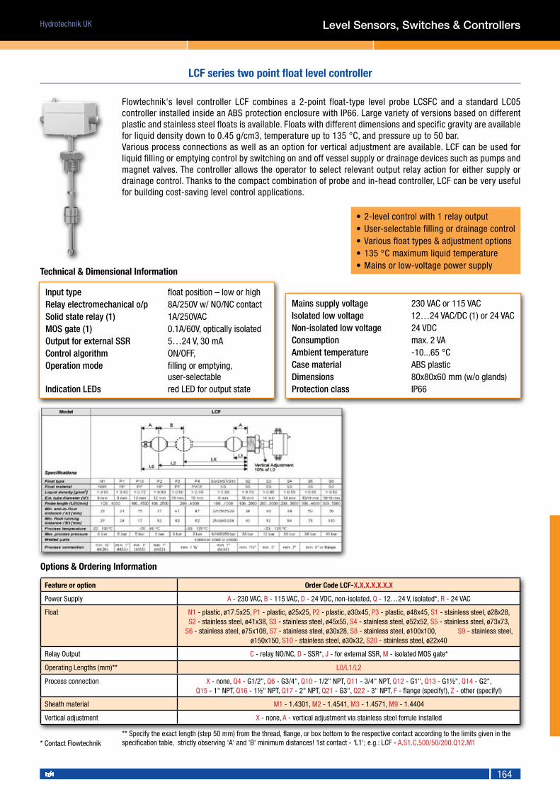
164
Hydrotechnik UK
164
Level Sensors, Switches & Controllers
• 2-level control with 1 relay output• User-selectable filling or drainage control• Various float types & adjustment options• 135 °C maximum liquid temperature• Mains or low-voltage power supply
Input type float position – low or highRelay electromechanical o/p 8A/250V w/ NO/NC contactSolid state relay (1) 1A/250VACMOS gate (1) 0.1A/60V, optically isolatedOutput for external SSR 5…24 V, 30 mAControlalgorithm ON/OFF,Operation mode filling or emptying, user-selectableIndication LEDs red LED for output state
Mains supply voltage 230 VAC or 115 VACIsolated low voltage 12…24 VAC/DC (1) or 24 VACNon-isolated low voltage 24 VDCConsumption max. 2 VAAmbient temperature -10...65 °CCasematerial ABS plasticDimensions 80x80x60 mm (w/o glands)Protection class IP66
LCF series two point float level controller
Feature or option Order Code LCF-X.X.X.X.X.X.X
Power Supply A - 230 VAC, B - 115 VAC, D - 24 VDC, non-isolated, Q - 12…24 V, isolated*, R - 24 VAC
Float N1 - plastic, ø17.5x25, P1 - plastic, ø25x25, P2 - plastic, ø30x45, P3 - plastic, ø48x45, S1 - stainless steel, ø28x28, S2 - stainless steel, ø41x38, S3 - stainless steel, ø45x55, S4 - stainless steel, ø52x52, S5 - stainless steel, ø73x73,
S6 - stainless steel, ø75x108, S7 - stainless steel, ø30x28, S8 - stainless steel, ø100x100, S9 - stainless steel, ø150x150, S10 - stainless steel, ø30x32, S20 - stainless steel, ø22x40
Relay Output C - relay NO/NC, D - SSR*, J - for external SSR, M - isolated MOS gate*
Operating Lengths (mm)** L0/L1/L2
Process connection X - none, Q4 - G1/2", Q6 - G3/4", Q10 - 1/2" NPT, Q11 - 3/4" NPT, Q12 - G1", Q13 - G1½", Q14 - G2", Q15 - 1" NPT, Q16 - 1½" NPT, Q17 - 2" NPT, Q21 - G3", Q22 - 3" NPT, F - flange (specify!), Z - other (specify!)
Sheath material M1 - 1.4301, M2 - 1.4541, M3 - 1.4571, M9 - 1.4404
Vertical adjustment X - none, A - vertical adjustment via stainless steel ferrule installed
Options & Ordering Information
* Contact Flowtechnik
Flowtechnik's level controller LCF combines a 2-point float-type level probe LCSFC and a standard LC05 controller installed inside an ABS protection enclosure with IP66. Large variety of versions based on different plastic and stainless steel floats is available. Floats with different dimensions and specific gravity are available for liquid density down to 0.45 g/cm3, temperature up to 135 °C, and pressure up to 50 bar. Various process connections as well as an option for vertical adjustment are available. LCF can be used for liquid filling or emptying control by switching on and off vessel supply or drainage devices such as pumps and magnet valves. The controller allows the operator to select relevant output relay action for either supply or drainage control. Thanks to the compact combination of probe and in-head controller, LCF can be very useful for building cost-saving level control applications.
** Specify the exact length (step 50 mm) from the thread, flange, or box bottom to the respective contact according to the limits given in the specification table, strictly observing 'A' and 'B' minimum distances! 1st contact - 'L1'; e.g.: LCF - A.S1.C.500/50/200.Q12.M1
Technical & Dimensional Information

Hydrotechnik UK
165
Float type ø45x55 mm, stainless steel
Liquid density 0.65 g/cm3
Measurement range ('L') 60...3000 mm
Resolution 6 mm or 12 mm
Signal type 4...20 mA, 2-wire
ZERO & SPAN adjustment ±20%, by multiturn trimmers
Maximum line load 750 Ω at 24V/20mA
Under-scale current limit 0.2 mA
Over-scale current limit 32 mA
Alarm contacts 2 NO contacts for Low / High level
Contactratings max. 60 V, max. 0.5 A, max. 10 W
Local indicator (1) (option) TI200-Y or TI200-Z
Loop supply voltage 8...32 VDC
Admissible variations 10% p-p at 50 Hz
Medium temperature -40...135 °C
Ambient temperature -20...70 °C (-20...60 °C for Ex housing)
Ambient humidity 0...95 %RH, non-condensing
Storage temperature -40...80 °C
Process pressure max. 20 bar
Wetted parts stainless steel
Process connection G2", NPT 2", or flange
Housing protective head or plastic box
Housing protection IP55...IP68 (depending on housing type)
The operation of the LCSF100 level transmitter is based on the switching of reed switches by a magnetic float, moving alongside a protective tube, and the reed switches act on the elements of a resistor matrix, changing the total matrix resistance in linear proportionality with the level measured. In addition to providing a 2-wire 4...20 mA output signal with 6 or 12 mm level resolution, the transmitter may be equipped with up to 2 alarm contacts. Moreover, LCSF100 can be equipped with an integrated loop-powered programmable indicator with independent alarm outputs. This level transmitter is very useful in applications where ultrasonic or capacitive transmitters would not work because of the foam, dense vapor, or non-homogeneous gas layer above the liquid surface.
• High reliability• 4...20 mA loop-powered output• Up to 2 alarm contacts• 135 °C maximum liquid temperature• Local programmable indicator available• ATEX certified Ex version available
Technical & Dimensional Information
Feature or option Order Code LCSF100-X.X.X.X.X.X.X.X.X
Housing B - head type "B", G - head type "G", D - plastic box 80x80x60 mm, DHW - head type "DHW", ES - head type "ES", EG - head type "EG", EGS - head type "EGS", EGW - head type "EGW", EX - explosion-proof instrument housing (specify!)
Alarm contact** X - none, A - N.O
Resolution 12 - 12mm, 6 - 6mm
Operating Lengths (mm)*** L0/L1/L2
Process connection Q14 - G2", Q17 - 2" NPT, Q21 - G3", F - flange (specify!), Z - other (specify!)
Sheath material M1 - 1.4301, M2 - 1.4541, M3 - 1.4571, M9 - 1.4404, M15 - 1.4362
Output signal X - none (4), F - 4…20 mA
Local indicator X - none, A - vertical indicator mounted (1)
Vertical adjustment X - none, A - vertical adjustment via stainless steel ferrule installed
Options & Ordering Information
*** Specify the exact length (step 50 mm) from the thread or flange bottom to the respective contact according to the limits given in the specification table, strictly observ-ing the minimum distances! e.g.: LCSF100 - B.AA.12.500/100/450 (In this case, measurement range L = 360 mm) ** First code High alarm, then code Low alarm
(1) With windowed head only! See indicator datasheet and order separately! 4) With local indicator only!
Level Sensors, Switches & Controllers
LCSF100 series float level transmitter

Hydrotechnik UK
166
Technical Information
MG1 series guided wave radar level sensor
The MG1 series uses TDR (Time Domain Reflectometry) technology: Energy optimized, high-frequency electromagnetic impulses, generated by the electronics, are propagated along the probe. When these impulses hit the surface of the media, part of the impulse energy is reflected back up the probe to the electronics. The level is calculated from the time difference between the impulse sent and the impulses reflected. The sensor can output the analysed level as a continuous measurement reading through its current output, and it can convert the one value into a freely positionable switching output signal. TDR Sensors are also known as Guided Radars or Guided Wave Radars (GWR).
Application AreasThe innovative TDR technology enables direct, precise and highly reliable continuous level measurement as well as point level detection in almost every liquid and solids–independent of changing process conditions (such as density, conductivity, temperature, pressure, vapour and turbulence). It is suitable for all types of process and storage tank applications and has an exceptional performance in media with low dielectric constant (i.e. low reflectivity) such as oils and hydrocarbons.
• Fast reaction time of 0,5 sec• Precise continuous level measurement and reliable point level detection in one device• For liquids as well as powdery solids suitable• No influences caused by tank / vessel internals• Unmatched price/performance ratio
Model Code Type Measuring Range
MG1-E Single Rod Probe 100 ... 3000mm
MG1-S Wire Rope Probe 1000 ... 20000mm
MG1-C Coaxial Probe 100 ... 6000mm
Options & Ordering Information
Level Sensors, Switches & Controllers
Accuracy ± 3mm or 0,03% of measured distance*Repeatability <2mm*Resolution <1mm*Ambient temperature -25°C to +80°CApplication temperature Single rod / wire rope probe: -40°C to +150°C Coaxial probe EPDM o-ring: -40°C to +130°C Coaxial probe FKM (viton) o-ring: -15°C to +150°CProcess connection Threads G¾"A, ¾” NPT (wrench size 32mm)Power supply 12 to 30 VDC (reverse polarity protected)Outputs Analogue: 4…20mA (active) Switch: DC PNP (active)Materials (wet) Single rod probe: 1.4404 / 316L, Peek, Ø 6mm Wire rope probe: 1.4404 / 316L, Peek, Ø 4mm Coaxial probe: 1.4404 / 316L, Peek, Ø 17,2mm and o-ring: EPDM or FKM (Viton)Protection class IP 68, NEMA6P (housing)

Hydrotechnik UK
167
Level Sensors, Switches & Controllers
• EEx ia IIC T4-T6 approved according to ATEX• IP68 protection• Up to 300 m measurement range• PUR sheathed cable with inner ventilation• 1000 N cable tensile strength
Supply voltage 10...30 VDCConsumption Max 28mAInput type hydrostatic pressureSensor element piezoresistiveSignal type 4...20 mA, 2-wireLine resistance max. 700 Ω at 24 VDCResponse time ≤ 1 msRepeatability ≤ 0.05% from spanOperating temperature -10...50 °CStorage temperature -30...80 °CTemperaturecompensation 0...50 °C Temperaturedrift 0.02...0.04 %/KCasingmaterial stainless steel 1.4571Protective cap PA plasticWiring PUR or Teflon® cableWeight 200 g plus 80 g/m cableProtection class IP68
LCSP series Hydrostatic level sensor
Technical Information
Ordering ExampleLCSP-131.0...4.B.150PU.Z0
Feature or option Order Code LCSP -
Variant 130, 131
Input range * RANGE - (see table above)
Contact function (no float) A - NO, B - NC, C - NO/NC
Cable length (metres) and type 1…300PU - polyurethane, 1…300TF - Teflon®
Preparation for Zone 0 X - none, Z0 - installed
Options & Ordering Information
* As per variant chosen
Dimensional Information

Hydrotechnik UK
168
TSOK measures temperature by the means of a Ptx sensitive element and converts it into standard 4...20 mA 2-wire current signal. This transmitter has a robust vibration-proof stainless steel sheath with IP65 protection class, and is equipped with a DIN 43650 connector that allows fast and easy electrical wiring. The probe interior is filled with special compound, which protects the electronics from the harsh ambient influences. Eight different temperature measurement ranges from -50 °C and up to 400 °C as well as customer specified ranges are available. Various stem diameters and lengths as well as stainless steel types are also available. Thanks to its small size and robust design, TSOK is applicable for cars, rail vehicles, construction machines, and other industrial equipment.
Input(RTD)type Pt100 or Pt1000 (w=1.385), class BMeasurement range -50...50 °C; -20...60 °C; 0...50 °C; 0...100 °C; -50...100 °C; 0...150 °C; 0...200 °C; 0...300 °C (1); 0...400°C(1,4)Range on request minimum span 50 °CSignal type 4...20 mA, 2-wireLinearity proportional to measured valueOutput at sensor burnout 32 mAOutput at sensor shorted 0.2 mAMeasurement error 0.2% from span or 0.2 °C (2)Non-linearity within measurement errorTemperaturedrift 0.01% from span for 1 °C
Loop voltage 10...32 VDCAdmissible variations 1 Vp-p at 50 HzMaximum line load 750 Ω at 24V/20mAMedium pressure max. 25 barAmbient temperature -40...85 °CAmbient humidity 0...95 %RHEM compatibility and safety according to EN 61000, EN 61010Sensor sheath stainless steelWiring 4-pin detachable connector DIN 43650Mounting thread M16, M18, M20, 3/8”, 1/2”, or otherStem diameter 6 or 8 mm Stem length 20...300 mm Extension length (1) 50...100 mm Protection class IP65
TSOK series OEM style temperature transmitter
• Pt100 or Pt1000 sensitive element• 2-wire 4…20 mA output• Easy & Fast connection plug M12• Vibration-proof design• Small & compact dimensions• Extended design for higher temperature available• High protection class - IP65• Local indicator available
Technical Information
Feature or option Order Code TSO-X.X.X.X.X.X.X.X.X.X.
Variant K - short-design, K1 - extended-design
Temperature range T17 - -50...50 °C, T10 - -20...60 °C, T18 - 0...50 °C, T19 - 0...100 °C, T12 - -50...100 °C, T20 - 0...150 °C, T7 - 0...200 °C, T23 - 0...300 °C (1), T8 - 0...400 °C (1,4), TZ - other (specify, ΔT ≥ 50 °C)
Stem diameter 6 - 6mm, 8 - 8mm
Stem length 'n' mm 20....300 - (step 5 mm)
Extension length (1) 'm' mm 50...100 - (step 5 mm)
Mounting thread Q0 - M16x1.5, Q1 - M18x1.5, Q2 - M20x1.5, Q3 - G3/8", Q4 - G1/2", Q9 - 3/8" NPT, Q10 - 1/2" NPT, QZ - other (specify!)
Sheath material M1 - 1.4301, M2 - 1.4541, M3 - 1.4571, M9 - 1.4404, M15 - 1.4362
Tip shape X - standard closed, N - narrowed
Options X - none, OP - electrochemically polished sheath surface
Local Indicator TI200 X - none, A - local indicator TI200 (3)
Options & Ordering Information
(4) Consult Flowtechnik(3) Ordered separately - consult Flowtechnik
(1) Only for extended length variant
(2) Whichever is greater
Temperature Transmitters

Hydrotechnik UK
169
The PPL8 sensor incorporates a pocket as well as a spring loaded insert which allows the sensor to be withdrawn extremely easily without breaking into the process line. We can manufacture the sensor stem in any immersion length and process connection to meet your exact requirements. A lagging extension can also be specified and with various options available for the terminal head, including IP68 stainless steel versions, we are sure to satisfy all of your requirements.
Sensor Type Platinum Resistance Thermometer—Pt100 or Pt1000
Operating Range -50 to 250°C (Unless Otherwise Requested)
Sheath Material 316 stainless steel
Tolerance Band Class B, Class A, 1/3 DIN, 1/5 DIN or 1/10 DIN
Wiring System 2, 3 or 4 wire, Simplex or Duplex
Head Types A - KNE Aluminium Alloy, IP68B - KSE Aluminium Alloy, IP68C - ABS, IP67D - Glass Filled Nylon, IP65E - 316 stainless steel, IP68(Other heads available upon request)
Head Options A - Ceramic Terminal BlockB - In Head Transmitter—SEM203P (Specify Range)C - Tails for Customers Own Transmitter
Sensor Type
Pt100 PPL8.A
Pt1000 PPL8.B
Immersion Length
Enter length in mm
Special codes
Refer to sales office
Number of wires
2 wire 2
3 wire 3
4 wire 4
Head Options
Block 1
Transmitter* 2
Tails 3
Number of detectors
Simplex S
Duplex D
Head Type
KNE A
KSE* B
ABS C
Nylon D
St/Steel ETolerance
Class A A
Class B B
1/3 DIN C
1/5 DIN* D
1/10 DIN* E
Thread size T
1/4"BSP A
1/2"BSP B
3/4"BSP C
1"BSP D
1/4"BSPT E
1/2"BSPT F
3/4"BSPT G
1"BSPT H
1/2"NPT I
3/4"NPT J
* Not available for Pt1000
* Not available with KSE head
Extension Length
Enter length in mm
PPL8 series Pt100 & Pt1000 temperature transmitter
Technical Information
Options & Ordering Information
Temperature Transmitters

Hydrotechnik UK
170
The PPL8 sensor incorporates a pocket as well as a spring loaded insert which allows the sensor to be withdrawn extremely easily without breaking into the process line. We can manufacture the sensor stem in any immersion length and process connection to meet your exact requirements. A lagging extension can also be specified and with various options available for the terminal head, including IP68 stainless steel versions, we are sure to satisfy all of your requirements.
Sensor Type Type J, K or T thermocouple
Operating Range -50 to 250°C (Unless Otherwise Requested)
Sheath Material 316 stainless steel
Tolerance Band BS EN 60584-2:1993 Class 1 or Class 2
Wiring System Simplex or Duplex
Head Types A - KNE Aluminium Alloy, IP68B - KSE Aluminium Alloy, IP68C - ABS, IP67D - Glass Filled Nylon, IP65E - 316 stainless steel, IP68(Other heads available upon request)
Head Options A - Ceramic Terminal BlockB - In Head Transmitter—SEM203P (Specify Range)C - Tails for Customers Own Transmitter
Thermocouple Type
Type J PPL8.J
Type K PPL8.K
Type T PPL8.T
Special codes
Refer to sales office
Head Options
Block 1
Transmitter* 2
Tails 3
Head Type
KNE A
KSE* B
ABS C
Nylon D
St/Steel E
* Not available with KSE head
Extension Length
Enter length in mm
Thread size T
1/4"BSP A
1/2"BSP B
3/4"BSP C
1"BSP D
1/4"BSPT E
1/2"BSPT F
3/4"BSPT G
1"BSPT H
1/2"NPT I
3/4"NPT J
Junction Type
Insulated 1
Grounded 2
Immersion L1
Enter length in mm
Number of detectors
Simplex S
Duplex D
PPL8 series type J, K & T thermocouple temperature transmitter
Technical Information
Options & Ordering Information
Instrumentation
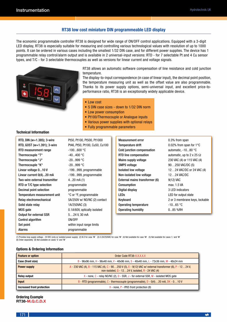
Hydrotechnik UK
171
Instrumentation
The economic programmable controller RT38 is designed for wide range of ON/OFF control applications. Equipped with a 3-digit LED display, RT38 is especially suitable for measuring and controlling various technological values with resolution of up to 1000 points. It can be ordered in various cases including the smallest 1/32 DIN case, and for different power supplies. The device has 1 programmable relay control/alarm output and is available in 2 universal-input versions: RTD - for 7 selectable Pt and 4 Cu sensor types, and T/C - for 3 selectable thermocouples as well as versions for linear current and voltage signals.
RTD,DIN(w=1.385);3-wire Pt50, Pt100, Pt500, Pt1000
RTD,GOST(w=1.391);3-wire Pt46, Pt50, Pt100, Cu50, Cu100
RTDmeasurementrange -100...600 °C
Thermocouple"T" -40...400 °C
Thermocouple"J" -20...999 °C
Thermocouple"K" -20...999 °C
Linear voltage 0...10 V -199...999, programmable
Linear current 0(4)...20 mA -199...999, programmable
Two-wireexternaltransmitter 4...20 mA (1)
RTDorT/Ctypeselection programmable
Decimal point selection programmable
Temperaturemeasurementunit °C or °F, programmable
Relay electromechanical 5A/250V w/ NO/NC (2) contact
Solid state relay 1A/250VAC (3)
MOS gate 0.1A/60V, optically isolated
Output for external SSR 5…24 V, 30 mA
Controlalgorithm ON/OFF
Set point within input range limits
Alarms programmable
Measurement error 0.3% from span
Temperaturedrift 0.02% from span for 1°C
Coldjunctioncompensation automatic, -10...80 °C
RTDlinecompensation automatic, up to 2 x 25 Ω
Mains supply voltage 230 VAC (4) or 115 VAC (4)
SMPS voltage 90…250 VAC/DC (5)
Isolated low voltage 12…24 VAC/DC or 24 VAC (4)
Non-isolated low voltage 12…24 VAC/DC
Externalmainstransformer(6) 9(12) VAC
Consumption max. 1.5 VA
Digital display 3 LED indicators
LEDs LED for output state
Keyboard 2 or 3 membrane keys, lockable
Operating temperature -10...65 °C
Operating humidity 0...85 %RH
(1) Provides loop supply voltage - 24 VDC (only w/ isolated power supply) (2) N.O for case 'M' (3) 0.2A/250VAC for case 'M' (4) Not available for case 'M' (5) Not available for cases 'L' and 'M' (6) Order separately (8) Not available on cases 'S' and 'M'
RT38 low cost miniature DIN programmeable LED display
• Low cost• 5 DIN case sizes - down to 1/32 DIN norm• Low power consumption• Pt100/Thermocouple or Analogue inputs• Various power supplies with optional relays• Fully programmable parameters
RT38 allows an automatic software compensation of line resistance and cold junction temperature.The display-to-input correspondence (in case of linear input), the decimal point position, the temperature measuring unit as well as the offset value are also programmable. Thanks to its power supply options, semi-universal input, and excellent price-to-performance ratio, RT38 is an exceptionally widely applicable device.
Technical Information
Feature or option Order Code RT38-X.X.X.X.X
Case (front size) B - 96x96 mm, H - 96x48 mm, V - 48x96 mm, S - 48x48 mm, L - 72x36 mm, M - 48x24 mm
Power supply A - 230 VAC (4), B - 115 VAC (4), C - 90…250 V (5), E - 9(12) VAC w/ external transformer (6), P - 12…24 V, non-isolated, Q - 12…24 V, isolated, R - 24 VAC (4)
Relay output X - none, C - relay NO/NC (2), D - SSR, J - for external SSR, M - isolated MOS gate
Input B - RTD (programmable), C - thermocouple (programmable), D - 0(4)…20 mA, DK - 0…10 V
Increased front protection X - none, P - IP65 front protection (8)
Options & Ordering Information
Ordering ExampleRT38-M.Q.C.D.X

Hydrotechnik UK
172
TI08 is a low cost, programmable process indicator designed for wide range of display applications with/without relay alarm. TI08 can be mounted in a panel cutout and it is equipped with a bright 4-digit LED display. This model is especially suitable for measuring and controlling various technological values from -1999 to 9999 with resolution of up to 6,000 points. The device can have up to two programmable relays providing on/off control/alarm, with or without pulse mode.
• Low cost
• 3 front sizes – up to 1/32 DIN
• 4-digit 14mm bright LED indication
• Universal linear input
• Up to 2 alarm relays available with pulsed output
• Fully programmable parameters
Input
Voltage linear 0 to 10 V or 0 to 5 V (1)
Current linear 0 to 20 mA or 4 to 20 mA
Other linear (on request) max. 40 V, max. 100 mA
Display limits -1999 to 9999, programmable
Decimal point position programmable
Power supply
Mains supply voltage 230 VAC (‘H’ and ‘L’)
SMPS supply voltage 90…250 VAC/DC (‘H’)
Low-voltage power supply 12…24 VAC/DC, 12DC, 9AC
Consumption max. 1.5 VA
Accuracy
Measurement error 0.3 % from span
Temperature drift 0.02 % from span for 1 °C
Indication and keyboard
Digital display 4 LED indicators, red
LED for relay status
Keyboard 2 membrane keys
Keyboard locking programmable
Output (up to 2 relay outputs)
Relay electromechanical 5A/250V, N.O/N.C or N.O contacts(2)
MOS gate 0.1A/60V, optically isolated
Solid state relay 1A/250VAC(1)
Output for external SSR 12(24)V/50mA
Control algorithm ON/OFF, pulse mode
Alarm parameters programmable
Design and materials 'H' 'L' 'M'
Dimensions (mm) 96x48 76x34 48x24
Mounting depth 100 55 43
Panel cutout [mm] 90x42 70x28 46x22
Maximum weight [g] 250 150 30
Protection, front/terminals IP65/20 IP65/20 IP54/20
Case material plastic
Wiring screw terminals
Operating conditions
Operating temperature -10 to 65 °C
Operating humidity 0 to 85 %RH
TI08 low cost programmeable LED display
TI08 accepts various linear input voltage or current signals. The display limits, decimal point position, measuring offset value as well as many other parameters are fully programmable. Thanks to its excellent price-to-performance ratio, the TI08 is a widely applicable device.
Feature or option Order Code TI08-X.X.X.X
Case (front size) H - 96x48 mm, L - 72x36 mm, M - 48x24 mm
Power supply A - 230 VAC(3), C - 90…250 V(4), D- 12 VDC, P - 12…24 VAC/DC
Relay output X - none, C - relay N.O/N.C(5), D - SSR, J - for external SSR, M - isolated MOS gate
Increased front protection X - none, P - IP65 front protection (6)
Options & Ordering Information
Ordering ExampleTI08-H.C.C.X
(1) 0.2A/250VAC for cases 'L' and 'M' (2) Only one relay 3A/250VAC w/ N.O contact for case 'M' (3) Not available for case 'M' (4) Not available for cases 'L' and 'M' (5) N.O for case 'M' (6) Not available for case 'M' (7) Available separately - consult Flowtechnik
Technical Information
Instrumentation

Hydrotechnik UK
173
• Flow rate & total display• LCD or selectable red or green backlit versions• 0.46" (11.7 mm) high digits• Optional relays, alarms, Analogue & comms. outputs• Operates from 9 to 28 vdc power source• Programmable scaling for count and rate• Bi-directional counting, up/down control• Quadrature sensing (up to 4 times resolution)• Built-in batch counting capability• Display color change capability at setpoint output• Dual input for A minus B function or direction• Programmeable update (values refresh) rates• IP65 front panel
Type Model No. Description Part number
CUB5CUB5R Dual Counter & Rate Indicator with Reflective Display CUB5R000
CUB5B Dual Counter & Rate Indicator with Backlight Display CUB5B000
Optional Plug-in Cards
CUB5RLY Single Relay Option Card CUB5RLY0
CUB5SNK Dual Sinking Open Collector Output card CUB5SNK0
CUB5COMRS485 Serial Communications Card CUB5COM1
RS232 Serial Communications Card CUB5COM2
Accessories
MLPS1 Micro-Line Power Supply, 85 to 250 VAC MLPS1000
CBLPRO Programming Cable RS232 (RJ11-DB9) CBLPROG0
CBPRO Programming Cable RS485 (RJ11-DB9) CBPRO007
SFCRD Crimson 2 PC Configuration Software for Windows 98, ME, 2000, XP SFCRD200
CUB5 low cost dual input LCD rate & total display
The CUB5 provides the user the ultimate in flexibility, from its complete user programming to the optional setpoint control and communication capability. The meter can be programmed as a single or dual counter with rate indication capability. The display can be toggled either manually or automatically between rate & total. The LCD is available in two versions, reflective (CUB5R000) and backlight (CUB5B000). The backlight version is user selectable for green or red backlighting with variable display intensity. The counter is programmable for one of eight different count modes, including bi-directional and quadrature. When programmed as a dual counter, each counter has a separate scale factor and decimal points.
In the counter/rate indicator mode, each have their own scaling and decimal point read-outs in different engineering units. The internal batch counter can be used to count setpoint output activations. The meter has two separate inputs which provide different functions depending on which operating mode is selected. Input A accepts the signal for the Count and/or Rate displays, while Input B accepts the signal for the Count display or direction control. The resulting display can be chosen as the sum or difference of the two inputs.
Options & Ordering Information
Dimensional Information
Instrumentation

Hydrotechnik UK
174
The PAX Analogue Panel Meters offer many features and performance capabilities to suit a wide range of industrial applications. Available in five different models to handle various analogue inputs, including DC Voltage/Current, AC Voltage/Current, Process, Temperature, and Strain Gauge Inputs.The PAXDP has the capability to accept two, 4-20 mA or 0-10 Vdc input signals. Each input signal can be independently scaled and displayed. In addition, various math calculations can be performed on the two signals.The PAX Digital Input Panel Meters are available in three different models, PAXC Counter/Dual Counter, PAXR Rate Meter and the PAXI which offers both counting and rate in the same package.
Dual analogue input PAXDPSingle analogue input PAXPThermocouple/RTD input PAXTStrain Gauge/Bridge Input PAXSAC True RMS Volt/Current Input PAXHFreq. Counter/Dual Counter PAXCFreq. Rate Meter PAXR Freq. Counter/Dual Counter & Rate PAXI
85 to 250 VAC 018-36 Vdc, 24 Vac* 1
1. DISPLAY: 5 digit, 0.56" (14.2 mm) red sunlight readable or standard green LEDs, (-19999 to 99999)
Type Model no. Description Part numbers
Optional Plug-InCards
PAXCDS
Dual Setpoint Relay Output Card PAXCDS10
Quad Setpoint Relay Output Card PAXCDS20
Quad Setpoint Sinking Open Collector Output Card PAXCDS30
Quad Setpoint Sourcing Open Collector Output Card PAXCDS40
PAXCDC
RS485 Serial Communications Output Card with Terminal Block PAXCDC10
Extended RS485 Serial Communications Output Card with Dual RJ11 Connector PAXCDC1C
RS232 Serial Communications Output Card with Terminal Block PAXCDC20
Extended RS232 Serial Communications Output Card with 9 Pin D Connector PAXCDC2C
DeviceNet Communications Card PAXCDC30
Modbus Communications Card PAXCDC40
Extended Modbus Communications Card with Dual RJ11 Connector PAXCDC4C
Profibus-DP Communications Card PAXCDC50
PAXCDL Analog Output Card PAXCDL10
PAX series analogue, frequency single & dual input LED rate & total displays
(Not available on PAXH) Any of the PAX meter can have alarms, comms., and/or a retransmitted analogue output capability by simply adding optional output cards. (see below)
Dimensional Information
Options & Ordering Information
Instrumentation
Red, Sunlight Readable Display 0Green Display 1
2. POWER: AC Versions: AC Power: 85 to 250 VAC, 50/60 Hz, 15 VA Isolation: 2300 Vrms for 1 min. to all inputs and outputs.DC Versions: DC Power: 11 to 36 VDC, 11 W (derate operating temperature to 40° C if operating <15 VDC and three plug-in option cards are installed)AC Power: 24 VAC, ± 10%, 50/60 Hz, 15 VA Isolation: 500 Vrms for 1 min. to all inputs and outputs (50 V working).

Hydrotechnik UK
175
The FT400 Series flow computers are microcontroller-based indicator/transmitters that display flow rate and total and provide output signals.
Model FT415 is battery powered and provides a scalable pulse output. The FT420 is powered by external DC voltage and has both pulse and 4-20 mA analog outputs. When the FT420 is being used in the 4-20 mA mode, it is a “two-wire” or “loop-powered” device, meaning that the 4-20 mA output signal doubles as its power supply.
Model FT415 Model FT420
Power Lithium "C", 3.6 Vdc, replaceable, 3-5 year life 12-30 Vdc, 4mA (4-20 mA when loop-powered)
Display
Rate 6-digit autorange, 1/2" character height 6-digit autorange, 1/2" character height
Total 8-digit, 5/16" character height 8-digit, 5/16" character height
Output
Current Sinking Pulse Scaled Pulse output (0.1 sec duration 6.1 Hz max) (or High Alarm output or Low Alarm output)Sensor pass-through Pulse output (unscaled)
Analogue None 4-20 mA loop; 24-30 Vdc
Pulse Output Range 0.1 - 9999999.9 units/pulse 0.1 - 9999999.9 units/pulse
Input Micropower GMR Sensor (square wave) 5V pulse or contact closure
Input Range 1.0 - 150 pulses/second 1.0 - 1,500 pulses/second
K-Factor Range .001 - 99999.999 .001 - 99999.999
Flow Alarm Output Range .01 - 999999.99 .01 - 999999.99
Operating Temperature -30˚ to 65˚ C (-22˚ to 148˚ F) -30˚ to 65˚ C (-22˚ to 148˚ F)
Environmental NEMA 4X, IP66 NEMA 4X, IP66
AccessoriesProtective cover, hinged = 30785Mounting kit, wall-to-meter conversion = MK10Mounting kit, meter-to-wall conversion = MK20LMI pulse out cable = 12010
FT400 series wall mounting frequency LCD rate & totalising display
• Rugged industrial IP66 housing• Battery or DC powered options• Wall or Meter mount options
Dimensional Information
Options & ordering Information
Technical Information
Instrumentation

Hydrotechnik UK
176
BT universally mounting totalising LCD display
• Battery powered or 8-24 Vdc• Dual totalizer and scaled pulsed output• IP66/67 and ATEX design• 8 digit LCD cumulative totaliser and large 5 digit resettable totaliser • Robust field or meter mountable housing with protection cover• Simple PIN protectable programming• Accepts universal pulse inputs• Long battery life• Reverse polarity protection
The BT programmable self powered totaliser is specifically designed for computing & displaying totals from flowmeters or machinery with frequency, sine wave or pulse outputs. The instrument simultaneously displays resettable (batch) total & a cumulative total in engineering units as programmed by the user. Ultra low power consumption is a result of innovative design which provides as much as 10 years of service from the replaceable 3.6V lithium battery. The BT may also be externally powered by 8~24Vdc.
Pulse OutputsThe pulse output can be set as either a scaled or unscaled pulse & is NPN/PNP selectable. The unscaled pulse serves as a frequency amplifier for turbine or paddle wheel style flowmeters.
ProgrammingSimple PIN protected flow chart programming with English prompts guide you through the programming routine, greatly reducing the need to refer to the instruction manual.
Liquid crystal display (LCD) alpha numeric LCD characters
Resettable total 5 digit x 7.5mm high, programmable to 3 decimal places
Accumulated total 8 digit x 3.6mm high, programmable to 3 decimal places
Engineering units displayed litres, MLitres, gallons, Mgallons, m3, lbs, kgs or no engineering units displayed
Input types (pulse & frequency) reed switch, open collector, coil (15mV P~P min.), voltage, current, namur & other proximities
Max. input frequencies coil 5Khz, hall 2.5Khz, namur 250hz
Input scaling range 0.001~9,999,999.999 with 3 floating decimal points
Pulse outputs NPN/PNP selectable, non-scaleable (5Khz max.) or scaleable (8hz max.). The scaleable pulse output has a pulse width of 60msec
Operating temperature -20~+80°C (- 4~176°F), consult Flowtechnik for higher / lower temp.
Power source 1 x 3.6V lithium battery, can last up to 10 yrs.
External powering 8~24Vdc (drives output & backlighting)
Intrinsic safe option Exia llB T4
Enclosure IP66/67 (NEMA 4X) glass reinforced nylon, 175g (0.4lb)
Electrical supplied with gland to suit 3-6mm (0.1- 0.2”) dia. cable
Mounting meter mount, wall, surface, pipe & panel
Technical Information
Instrumentation

Hydrotechnik UK
177
Options & Ordering Information
cumulative & batch (reset) FBT110D0totaliser with pulse output
Optionsintrinsically safe to Exia IIB T4 I
backlighting of LCD display B(requires external dc power)
Housing typeuniversal mount (field, surface, FMpipe, wall or panel mount)
integral meter mount MM
meter mountedpanel mounted pipe mounted
Optional adaptors
AWMstainless steel wall mount kit
ATMfixed stem for Turbine meters
APMstainless steel 2” pipe mount kit
AUSswivel stem for Turbine meters
ACFcooling fin for hi temp. flowmeters
ACGadditional cable gland
Dimensional Information
BT universally mounting totalising LCD display
Instrumentation

Hydrotechnik UK
178
The RT is a fully programmable self powered flow rate totaliser specifically designed for computing & displaying flow rates & totals from flowmeters or machinery with frequency, sine wave or pulse outputs. The instrument displays instantaneous flow rate, resettable (batch) total and a cumulative total in engineering units as programmed by the user. The integral 3.6V replaceable lithium battery supports the rate & total displays and provides as much as 10 years of service.
Outputs (...if externally powered)An unscaled pulse output serves as an input signal amplifier ideally suited for coil type inputs from turbine or paddle wheel meters. The output can be transmitted over long distances & is NPN/PNP selectable (current sinking or current sourcing). Alternatively a scaleable pulse output is available which is NPN/PNP selectable to facilitate input to any variety of PLC, counter or to drive a relay. The RT also has low and high flow alarms, 4-20mA output, 10 point linearisation of flow input & the capability of adding, subtracting or rationing of two separate flow inputs.
ProgrammingSimple PIN protected flow chart programming with English prompts guide you through the programming routine, greatly reducing the need to refer to the instruction manual.
• Battery powered or 8-24 Vdc• Dual flow inputs (A+B, A-B, A÷B)• Dual totalizer and scaled pulsed output• IP66/67 and ATEX design• 8 digit LCD resettable & cumulative totaliser, 5 digit rate display• Simple PIN protectable programming• Scaleable flow inputs• Multipoint linearity correction• Long battery life• Non volatile memory• Low frequency cutoff
Liquid crystal display (LCD) 9mm high alpha numeric characters + subscripts
Instantaneous flow rate 5 digit to 3 decimal places, units/sec, /min, /hr or /day
Resettable & accumulated totals 8 digit, programmable to 3 decimal places
Engineering units displayed litres, MLitres, gallons, Mgallons, m3, lbs, kgs or no engineering units displayed
Input types (pulse & frequency) reed switch, open collector, coil (15mV P~P min.), voltage, current,namur & other proximities, voltage & current pulses
Dual inputs (A&B) A+B, A-B, or A÷B (all outputs correspond)
Input frequency range (rate) 0.1hz to 10Khz ( with programmable low frequency cut-off )
Input scaling range 0.001~9,999,999.999 with 3 floating decimal points
Linearisation 10 point correction, best under external power
Operating temperature -10~+80°C (14~176°F), refer factory for higher / lower temp.
Power sources one 3.6V lithium battery, 8~24Vdc external source and/or 4~20mA loop powered.
Also with PM version 95~260Vac (DIN panel mount version)
Rate Outputs 4~20mA into 750Ω @24Vdc, resolution 0.25% of span, low & high flow alarms (NPN/PNP solid state & relay options)
Pulse outputs NPN/PNP selectable, non-scaleable (10Khz max.) or scaleable (50hz max.), auto-ranging pulse width: 1000 ÷ (hz x 2) = msec, max 300msec,1A max.
Enclosures (two styles) IP66/67 (NEMA 4X) GRN field mount or DIN panel mount
Intrinsic safe option Exia IIB T4
Mounting flexibility meter mount, wall, surface, pipe or panel mount
Technical Information
RT Universal or DIN mount dual input rate & total LCD display
Instrumentation

Hydrotechnik UK
179
Options & Ordering Information DIN panel mounting version
Function
Flow rate totaliser with 4~20mA, FRT12scaleable pulse & alarm outputs, dual flow inputs & IP68
Function
Flow rate totaliser with 4~20mA, FRT12scaleable pulse & alarm outputs, dual flow inputs & IP68
Flow input type
Digital (pulse or frequency) D
Flow input type
Digital (pulse or frequency) D
Power supply
Self powered (battery) or regulated 8~24Vdc 0(transformer is removed for vehicle mounts)
Housing type
Universal mount ( field or panel ) (GRN housing) FM
Integral meter mount (only order MM when MMretro fitting an instrument to a OM series pulse meters) (GRN housing)
Universal mount (field or panel) FA(Alloy housing- RT12 & RT20)
Integral meter mount (only order MM when FMretro fitting an instrument to a OM series pulse meters) (Alloy housing- RT12 & RT20)
Free standing Exd Aluminum explosion proof EXhousing with external switches
Turbine mount Exd Aluminum explosion proof EYhousing with external switches
Free standing Exd 316SS explosion proof EShousing with external switches
Turbine mount Exd 316SS explosion proof EThousing with external switches
Options
Clear silicone bezel boot (seals entire Sbezel whilst maintaining touch key sensitivity)
Electrical options
I.S intrinsically safe toExia IIB T4 - IIECEX & ATEX approved
Mechanical options
Facia protector (RT12 Alloy housing) P3mm clear polycarbonate protection plate
Electrical access
M20 x 1.5mm (M16 x 1.5mm for RT20 only) 1 female threaded conduit entry ports (sealedentry ports remain IP66/67 when not used)
1/2" NPT female threaded conduit entry 2ports (sealed entry ports remain IP66/67 when not used)
Electrical access
M20 x 1.5mm (M16 x 1.5mm for RT20 only) 1 female threaded conduit entry ports (sealedentry ports remain IP66/67 when not used)
1/2" NPT female threaded conduit entry 2ports (sealed entry ports remain IP66/67 when not used)
Power supply
Self powered (battery) or regulated 08~24Vdc (transformer is removed for vehicle mounts)
110Vac (can also be powered by 8~24Vdc) 1
220Vac (can also be powered by 8~24Vdc) 2
Housing type
DIN panel mount 96 x 96 (3.8") bezel 91 x 91 PM(3.5") cut out,110mm (4.3") deep
Instrument supplied fitted to an IP66 field FEenclosure (FE) also includes clear bezel boot
Options & Ordering Information Universal mounting versions
Dimensional Information
RT Universal or DIN mount dual input rate & total LCD display
Instrumentation

Hydrotechnik UK
180
pulse input, w/ programmable mechanical contact (NO) or active front electronic (from PNP / NPN sensor)analogue input, programmable(1) 0(4)...20 mA or 0...5(10) VInputCLEAR resets counter to '0' (4 functions)InputGATE enables pulse countingInputDIRECTION(2) changes counting directionMaximum input frequency 5 kHzInput filter for suppression of contact bouncingPrescaler coefficients 1...9999, multiplying and dividingInput isolation (option) optical, 1500 VACRelay electromechanical o/p 5A/250V w/ N.O/N.C (2) contactSolid state relay o/p(4) 1A/250VACMOS gate 0.1A/60V, optically isolated Transistorgate(5) open collector, 40mA/40VOutput for external SSR 5…24 V, 30 mARelay action according to the mode (7)Output pulse duration 0.1...99.9 s, programmableAnalogoutput(6) 0(4)…20 mA or 0…10 V, isolated
PV display 6 LED indicators, 9mmSP display(1) 6 LED indicators, 9mLEDs 2 LEDs for output state Mains supply voltage(1) 230 VAC or 115 VACSMPS voltage 90…250 VAC/DC (5)Isolated low voltage 12…24 VAC/DC or 24 VAC (1)Non-isolated low voltage 12…24 VAC/DCConsumption max. 6 VAOperating temperature -10...65 °COperating humidity 0...85 %RHStorage temperature -20...65 °CStorage humidity -20...65 °C 0...95 %RH, non-condensingOperating modes 7 (incl. dosing mode)Countingmodes pulse counting and batch countingCountingrange 0...2147483647Programming through keyboard
CT34 low cost pulse counter, RPM meter & batch controller
CT34 is a sophisticated new-generation counter equipped with a 6-digit display, which can hold up to 999999 count units or batches, and may have up to 2 programmable relay outputs and an analog output for alarm signaling or process controlling. CT34 is available as a counter, as an R.P.M. meter, and as a combination of both. As a counter, this model allows programming of 7 different counting and output-relay-action modes (including dosing mode) as well as counting pulses or pulse batches. The R.P.M meter variant has 6 operating modes. Besides its counting input, CT34 has 3 additional inputs – CLEAR, GATE, and DIRECTION – and a user programmable software input filter. Other useful features include fraction number coefficient prescaler and programmable actual and displayed counting directions. With its various features and flexible programmable internal structure, the CT34 counter is a widely applicable device.
• Available as a totaliser, RPM meter or combined • One or two 6-digit LED displays• Pulse and analogue input versions• Programmable divider and multiplier• Pulse counting and batch counting • 6 selectable modes plus dosing mode• Up to 2 programmable relay outputs
Feature or option Order Code CT34-X.X.X.X.X
Variant C - totalizing counter, R - R.P.M. meter, CR - combined
Case (front size) H - 96x48 mm, S - 48x48 mm, L - 72x36 mm
Power supply A - 230 VAC(1), B - 115 VAC(1), C - 90…250 V, P - 12…24 V, non-isolated, Q - 12…24 V, isolated(4), R - 24 VAC(1)
Counting input P - pulse, A - analogue(1)
Relay output X - none, C - relay N.O/N.C(3), D - SSR(4), E - open collector NPN(5), J - for external SSR, M - isolated MOS gate
Analogue output(6) X - none, E - 0…20 mA, F - 4…20 mA, K - 0…10 V
Input isolation X - none, I - input isolation
Increased front protection X - none, P - IP65 front protection (9)
Options & Ordering Information
Ordering ExampleCT34-C.H.C.P.C.X.X.X
(1) Available ONLY for case 'H' (2) Only with pulse input type!(3) N.O for case 'L'
(4) Ask for availability! (5) ONLY with isolated power supply! (6) Instead of second relay
Technical Information
Instrumentation

Hydrotechnik UK
181
The FT500-Series is a batching flow processor with additional output controls. It is designed for use with flow meters and flow sensors which have frequency output proportional to flow. In addition to batch functions, the FT500-Series indicates flow rate, and other data in large 3/8” (9.66 mm) digits on an easily-read, backlit display.
Units of measure are user selectable, and range from milliliters per second to millions of gallons per day. The unit can be 110 Vac powered with a standard 3-wire cord (included), 220 Vac powered (optional), or DC powered through an internal terminal strip (battery not included).
Power 115 Vac, 50/60 Hz @ 125 mA, 12 Vdc @ 750 mA or 10-16 Vdc (220 Vac optional)
Temperature 0˚ - 55˚ C
Enclosure Precision cast aluminium, NEMA 4X, panel or wall mount configuration
Batch Outputs Two form C (SPDT) relays, 115 Vac 6A max
Max Pulse Output 100 mA at 60 Vac/Vdc, opto-isolated, open-collector
Memory Type Non-volatile EEPROM with auto-backup
Sensor Power 12 Vdc, 10 mA
Display Totalizer = 8 digit Rate = 5 digit, backlit
Units Volume = Gallons, cubic feet, cubic meters, millions of gallons, millilitres, fluid ounces, pounds, litresTime = Seconds, minutes, hours, days
Analog Output 4-20 mA passive opto-isolated; 4-20 mA active; 0-5 Vdc, or 0-10 Vdc
Sensor Input 1-1000 Hz, ESD protected, interfaces to current sinking sensor output
Environmental NEMA 4X
Setup Memory Non-volatile EEPROM, auto-backup
FT500 series wall mount batch controller
• Rugged industrial IP66 housing• 2x change-over relays for 2 stage control• Dual line alphanumeric display
Technical Information
Dimensional Information
Options & Ordering Information
Instrumentation

Hydrotechnik UK
182
Control outputsTwo independent outputs can be programmed to provide stepped control at the start and/or end of each batch. DC powered models have two solid state control outputs, DIN models can be AC or DC powered and have two single pole double throw (SPDT) control 5A relays. An Automatic Overrun Compensation feature corrects for any batch errors attributed to slow closing valves or flow rate variations.
Network interlocksAs many as 9 Ecobatch controllers may be networked together, typical applications are where one liquid is being dispensed to a number of outlets or a number of different liquids are being batched via one common flowmeter. Ecobatch will also take an “inhibit start” signal from other control or plant equipment.
ProgrammingSimple PIN protected flow chart programming with English prompts guide you through the programming routine greatly reducing the need to refer to the instruction manual.
EB series two stage batch controller
• Large 8 digit batch & cumulative total LCD • Robust IP66/67 wall/meter or panel mount • Simple PIN protectable programming• Scaleable flow inputs • 2x switches for dual stage control• Automatic overrun compensation • Missing pulse (no flow) alarm • Maximum batch size limiting • Non volatile memory • Multiple batcher interlock function • Remote Run, Stop, batch set, etc version
The EB Ecobatch is a fully programmable high speed batch controller specifically designed to operate with common pulse producing flowmeters such as positive displacement, turbine, mass, vortex or magnetic style. The instrument displays batch value, batch progress & cumulative total in engineering units as programmed by the user, it also logs the total number of batches performed and total volume dispensed.
Ecobatch scrolls messages to prompt the user at each stage of operation. Batch limiting and no-flow detection are “safeguards” against erroneously high batch entries, loss of the flow input signal or contr ol valve or pump failure.
Liquid crystal display (LCD) 9mm high alpha numeric characters + subscripts
Batch & accumulated totals 8 digit, programmable to 3 decimal places
Engineering units displayed litres, MLitres, gallons, Mgallons, m3, lbs, kgs or no engineering units displayed
Input types (pulse & frequency) reed switch, open collector, coil (15mV P~P min.), voltage, current,namur & other proximities. Max. frequency 10kHz
Input scaling range 0.001~9,999,999.999 with 3 floating decimal points
Control outputs (field mount) Two 1A NPN open collectors, 24Vdc max.
(panel mount) Two SPDT 5A relays (with DIN versions)
Alarm output (no flow alarm) 1A open collector ( NPN/PNP selectable ), 24Vdc max.
Operating temperature -10~+80°C (14~176°F), refer factory for higher / lower temp.
Power requirements 12~24Vdc, 50mA, 95~260Vac (DIN version)
Status interlocks Batch status output, batch inhibit input, network looping
Enclosures (two styles) IP66/67 (NEMA 4X) GRN field mount or DIN panel mount
Mounting flexibility meter mount, wall, surface, pipe or panel mount
Batching systems example Ecobatch with flowmeter & control valve eg: UM020 system
Technical Information
Instrumentation

Hydrotechnik UK
183
Function
Ecobatch 12-24vdc powered one or FEB10two stage batch controller
Electrical access
M20 x 1.5mm (M16 x 1.5mm for RT20 only) 1 female threaded conduit entry ports (sealed entry ports remain IP66/67 when not used)
1/2" NPT female threaded conduit 2entry ports (sealed entry ports remain IP66/67 when not used)
Flow input type
Digital (pulse or frequency) D
Housing type
Universal mount (field or panel) FM(GRN housing)
Integral meter mount (only order MM MMwhen retro fitting an instrument to a OM series pulse meters) (GRN housing)
Free standing Exd Aluminum explosion proof EXhousing with external switches
Turbine mount Exd Aluminum explosion proof EYhousing with external switches
Free standing Exd 316SS explosion proof EShousing with external switches
Turbine mount Exd 316SS explosion proof EThousing with external switches
Function
AC or dc powered ecobatch one or two FEB10stage batch controller with two SPDT x 5A control relays
Flow input type
Digital (pulse or frequency) D
Power supply
Self powered (battery) or regulated 8~24Vdc 0(transformer is removed for vehicle mounts)
110Vac (can also be powered by 8~24Vdc) 1
220Vac (can also be powered by 8~24Vdc) 2
Housing type
DIN panel mount 96 x 96 (3.8") bezel 91 x 91 PM(3.5") cut out,110mm (4.3") deep
Instrument supplied fitted to an IP66 field FEenclosure (FE) also includes clear bezel boot
Options
Clear silicone bezel boot (seals entire Sbezel whilst maintaining touch key sensitivity)
Electrical access
Rear terminal connections, DIP switches & 0 8~24 Vdc source regulation
EB series two stage batch controller
Dimensional Information
Options & Ordering Information Universal mounting version
Options & Ordering Information DIN panel mounting version
Instrumentation

Hydrotechnik UK
184
The A055 is a blind (non indicating) 4-20 mA transmitter, designed for use with almost all flow sensors. It accepts a pulse frequency input from the flow sensor, and converts this input into a continuous analogue output signal. Power for the transmitter is taken from the current loop itself, so only two wires are required.
The digital design makes it possible to span the unit in the field without tools. The frequency at which 20 mA is desired is entered on a set of rotary switches, and an internal microcontroller automatically scales all other values accordingly. An additional benefit of the microcontroller is its ability to average inputs, for smoothing of the output signal. The degree of averaging can be selected in the field, from 2 to 16 seconds.
Power 24 - 36 Vdc
Temperature 0˚ - 55˚ C
Input Open-collector solid state sensor
Input Averaging 2 - 16 seconds (switch selectable)
Response Time 2-60 seconds; 90% of full scale (dependent on input averaging)
Frequency
Minimum 10 Hz (@20 mA)
Maximum 999.9 Hz
Setting 4 Rotary DIP switches
Output Proportional 4-20 mA
A055 series Wall mount frequency to analogue convertor
• Rugged industrial IP66 housing• Cost effective alternative for converting pulses to 4-20 mA• Easy set up with rotary switches
Technical Information
Instrumentation

Hydrotechnik UK
185
The PS40 is a low voltage device that allows a flow sensor to drive multiple (up to four) pulse responsive devices, such as solenoid driven chemical metering pumps, counter timers, or remote totalizers. It requires an external DC power supply for operation and can provide power to a single low power flow sensor. A DC power supply of 10 to 36 Vdc is required. Three of the outputs are transistor, the fourth is relay. The relay output is identified by its terminals marked N.O (normally open), COM (common), and N.C (normally closed). The relay output will operate essentially everything, including the very rare pump or control that will only work with dry contact.
Power 10 - 36 Vdc
Relay Operational frequency = 50 Hz maxContacts = 250 mA max, 36 Vdc max, 3W max
Optoisolation 10 mA max @ 30 Vdc max
Outputs Three open collector optoisolated One Form C relay
PS40 wall mounted pulse splitter
Designed for use as a meter accessory, the PD10 divider is used primarily for pacing electronic metering pumps. Any number from one to 9999 can be set on rotary switches. Each time the divider has received the set number of pulses from the meter, it puts out one pulse to stroke the pump. The PD10 is also useful in boiler and cooling tower feed and bleed operations, and for lowering frequency output of high frequency meters. The PD10 creates a programmable pulse meter with an easily adjustable pulse rate.
Wall (Pump) Mount Encl. Epoxy-encapsulated ABS housing with cover
Meter Mount Enclosure Cast aluminium sealed housing
Temperature 0˚ to 130˚ F (-18˚ to 55˚ C)
Divider Range 1 to 9999
Setting Mechanism Rotary switches
Power 7 - 30 Vdc @ 4 mA
Maximum Sensor Load 20 mA
Maximum Input Frequency 350 Hz (pulses/second)
Maximum Output Frequency 8 Hz (pulses/second)
Output Solid state relay; 0-250 V, 170 mA max AC/DC
Output Pulse Width 0.1 second
Wall Mount Input Connection Seametrics connector
Meter Mount Input Connection Terminal
Wall Mount Output Connection Pump connector on 24 inch lead
Meter Mount Output Connection Comes with 18 foot lead
• Rugged wall mount enclosure• 3x transistor and 1x relay output• Cost effective method for driving multiple instruments
Technical Information
• Rugged wall mount housing (meter mount option)• Volt-free contact closure output• Cost effective method for reducing frequency output for low speed inputs
Technical Information
PD10 wall mounted pulse divider
Instrumentation

Hydrotechnik UK
186
The DL76 is a battery powered data logger that can be used with any Seametrics flowmeter or other device (contact Flowtechnik). It stores pulses for up to 3 years, depending on the user selected frequency of reading. Indicator lights on the unit flash to indicate when it is functioning and when the battery is low.
The DL76 can be factory mounted on the meter or remotely (wall) mounted. Housings are rugged cast aluminum, gasketed for environmental protection.
Power Size C 3.6 Vdc lithium battery (included)
Battery Life ~3 years (varies with sampling interval)
Temperature 0˚ to 130˚ F (-18˚ to 54˚C)
Rate Units
Volume mL, liter, gallon, Imperial gallon, cubic foot, cubic meter, million gallon
Time Seconds, minutes, hours, days
Total Units Liter, gallon, Imperial gallon, cubic foot, cubic meter, Mgallon, acre-foot, acre-inch, megaliter, thousand-gallon
Data Storage Capacity
Capacity at Sampling Interval
11 days at 15 seconds
22 days at 30 seconds
44 days at 60 seconds
6 months at 240 seconds
1 year at 480 seconds
3 years at 1450 seconds
Max Input Frequency 500 Hz
Indicators Low battery; Power
Memory Wraparound Selectable options (Stop or Overwrite)
Clock Accuracy 10 minutes/month (.02%)
DL76 Wall mounting pulse datalogger
When a DL76 logger is placed into operation, it is easily set up using a laptop computer. Data is also retrieved from the DL76 by means of a laptop and can be analyzed on the laptop or easily loaded on a desktop computer for analysis.*FlowInspector version 2 software (ordered separately) is required for the downloading, storing, viewing, graphing, charting and printing of data in several formats. FlowInspector requires a PC with Windows 98, NT, 2000, XP, Vista or Windows 7; CD-Rom drive; 800 x 600 screen resolution; serial port or USB/serial adapter; and a Seametrics DC3 data cable. FlowInspector can be used with an unlimited number of dataloggers.
• Rugged Industrial housing• Battery powered• Meter or remote mount option• c/w software and cables
Technical Information
Option & Ordering Information
Dimensional Information
Instrumentation

Hydrotechnik UK
187
The MultiLog SRD-99 device is designed to record and display current values as well as to present technological parameters in the form of graphs. The device is equipped with eight temperature (Pt100/500/1000) or current (in the 0/4-20mA standard) inputs, one pulse (digital) input for controlling the recording process and one USB Host port for flash data storage.
Internal memory has 2MB capacity (0.5 million data recordings altogether) or 8MB in version with USB port (2 million data recordings). However when a USB flash drive is plugged permanently, it can significancy extend the recording time without a need of data transferring from the SRD-99 to a PC. For example: 1 GB flash drive allows continuous data recording for over 1 year (8 channels record every 1 sec., approx 250 millions data recordings)! Individual alphanumeric description (text) of each recorded channels is possible. The multi-language menu assisted with full text descriptions make the unit configuration process quite easy.
The history of the process in time
Logging parameters Device information
8 channel view displayed at the same time
Main menu of the unit
The current value of the measurement signal Height of the digits: 18mm
SRD-99 series multichannel analogue datalogging LCD display & software
• 96x96 panel mount design• up to 8 Analogue or Temperature (Pt) inputs• S485 or USB communications (optional)
Power supply: 19V 50 V DC; 16V 35V AC or 85 260V AC/DC, all separatedPower consumption: typical 7 VA; max. 12 VADisplay: graphic LCD, 128 x 64 points, with backlightMeasuring inputs: 1, 4 or 8; Pt100; Pt500; Pt1000(2 and 3-conductor connection) or 0/4-20mA inputs; common groundMeasuring range: ±9999 + decimal point (current inputs); -100°C +600°C (RTD inputs) with resolution 0,1°CDigital input: 1 input 24V DC, otocoupiedOutputs: 2 electronic relays (ER1, ER2) with max. load 24V AC (35 V DC) / 200 mASensors supply (only current version): 24 V DC ±5%, max. 200mA, not separated from measuring inputsCommunicationinterface: RS-485 (Modbus RTU) or USB Host port, galvanically separatedTransmissionspeed: 1200-115200 bit/secInternal memory capacity: 2 MB (0.5 million data recordings) in version without USB, 8 MB (above 2 million data recordings) in version with USB Host portTypeofprotection: Version without USB: IP 65 (front), available options: additional frame IP 65 for panel cut-put sealing, transparent door STD-99version with USB: a) IP 40, b) IP 54 (when fitted with STD-99 transparent door)Workingtemperature: 0°C +50°CStorage temperature: -10C +70°CCase: boardCasematerial: NORYL-GFN2SE1Casedimensions: 96 x 96 x 100 mmPanel cut-out dimensions: 90,5 x 90,5 mmInstallation depth: min. 102 mmBoardthickness: max. 5 mm
Technical Information
Instrumentation

Hydrotechnik UK
188
SRS-U/4-Z45converter USB/RS-485
Loggy softThe loggy soft program enables the visualisation, archiving and printing of measurements (e.g. temperature, humidity, pressure) stored in the SRD-99 device memory. Work with SRD-99 type devices takes place through an RS-485 serial interface or portable flash disk devices plugged into the USB port. Connecting a network of units to a serial port (RS-232) or USB port of a PC is possible thanks to a converter (RS-485 to RS-232 or RS-485 to USB) manufactured to suit.
S-ToolkitThe S-Toolkit software enables configuration reading and writing operations, updating the device firmware and obtaining basic information on SRD-99 type devices through RS-485 serial interface or portable flash disk devices plugged into the USB port. This application enables to quickly and easily define device parameters in one of three possible configuration models. The set of parameteres can be transmitted directly to the device or stored in a file for future use.
SRS-2/4-Z45converter RS-232/RS-485
Options & Ordering Information
Number of inputs
1
4
8
Options
no options 00
IP 65 frame (version without USB) 01
USB host port provided with 0Bprotective cap
Portable case P130 (front USB 0JHost, no alarm connectors)Types of inputs
current 0/4-20mA 1
RTD (Pt100, Pt500, Pt1000) 3Power supply
24V AC/DC 3
85V-260V AC/DC 4
SRD-99 series multichannel analogue datalogging LCD display & software
Signal convertors
Analysis & Configuration Software
Instrumentation
SRD99

Hydrotechnik UK
189
Notes