Embed Size (px)
Citation preview

CATALOG2017
2017.4 industrial.panasonic.com/
Surge Absorbers

– 1 –
Surge Absorbers CONTENTS
All products in this catalog comply with the RoHS Directive.
The RoHS Directive is “the Directive (2011/65/EU) on the Restriction of the Use of Certain
Hazardous Substances in Electrical and Electronic Equipment “ and its revisions.
Product Item Type / Series Part Number Page
“ZNR” Transient / Surge Absorbers 2
Products System 3
“ZNR” Transient/
Surge Absorbers
Type D, Series V
Standard Products ERZV□□D□□□ 4
Leads Cut Type ERZV□□D(V)□□□CS/C1 24
Taping Specifi cations ERZV□□D(V)□□□ 25
Application Note for UL, CSA and VDE Recognized Components
27
Marking Contents 28
Performance Characteristics 29
Type D, Series E
Standard Products ERZE□□A□□□ 31
Leads Cut Type ERZE□□A(B)□□□CS 46
Taping Specifi cations ERZE□□E(F)□□□ 47
Application Note for UL, CSA and VDE Recognized Components
49
Marking Contents 50
Performance Characteristics 51
Handling Precautions (Type D, Series E) 53
Minimum Quantity / Packing Unit (Type D, Series E) 56
SMD TypeSeries HF ERZHF□□□□□ 57
Series VF ERZVF□□□□□ 60
Handling Precautions (Type D / SMD) 65
Type SC ERZVS□□□□□□ 68
Type E ERZC□□EK□□□(Y) 70
Type CK ERZC□□CK□□□ 76
Handling Precautions (Type SC / E / CK) 81
Type P ERZA□□PK□□□ 84
Type J ERZA□□JK□□□ 86
Type G ERZA□□GS(K)□□□ 89
“ZNR” Surge Absorber Units ERZA 91
“ZNR” Transient/Surge Absorbers, For Thyristor Protection
Type E ERZC□□EK□□□P95
Type J ERZU□□JP□□□
Minimum Quantity / Packing Unit 99
Apr. 201702
Design and specifications are each subject to change without notice. Ask factory for the current technical specifications before purchase and/or use.
Should a safety concern arise regarding this product, please be sure to contact us immediately.
“ZNR” Transient/Surge Absorbers
– 2 –
Vo
lta
ge
lo
g
Current log10-3 A
Maximum Clamping Voltage
Va
risto
r V
olta
ge
Max.
Min.
Nom.
Maximum Leakage Current
Voltag
e
Voltag
e
Time Time
Lightning Voltage Clumping Voltage by ZNR
Time
100
90
50
10
0
Curr
ent(
%)
8 μs
20 μs
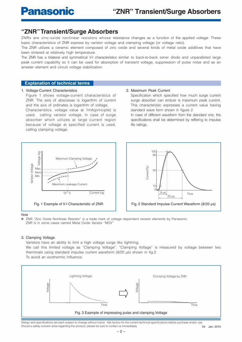
Explanation of technical terms
“ZNR” Transient/Surge Ab sorb ersZNRs are zinc-oxide nonlinear resistors whose resistance changes as a function of the applied voltage. These
basic characteristics of ZNR express by varistor voltage and clamping voltage (or voltage ratio).
The ZNR utilizes a ceramic element composed of zinc oxide and several kinds of metal oxide additives that have
been sintered at relatively high temperature.
The ZNR has a bilateral and symmetrical V-I characteristics similar to back-to-back zener diode and unparalleled large
peak current capability so it can be used for absorption of transient voltage, suppression of pulse noise and as an
arrester element and circuit voltage stabilization.
Fig. 1 Example of V-I Characteristic of ZNR Fig. 2 Standard Impulse Current Waveform (8/20 μs)
Note
✽ ZNR “Zinc Oxide Nonlinear Resistor” is a trade mark of voltage dependent resistor elements by Panasonic.
ZNR is in some cases named Metal Oxide Varistor “MOV”
3. Clamping Voltage
Varistors have an abitity to limit a high voltage surge like lightning.
We call this limited voltage as “Clamping Voltage”. “Clamping Voltage” is measured by voltage between two
therminals using standard impulse current waveform (8/20 μs) shown in fig.2.
To avoid an exothermic influence.
Fig. 3 Example of impressing pulse and clamping Voltage
1. Voltage-Current Characteristics
Figure 1 shows voltage-current characteristics of
ZNR. The axis of abscissas is logarithm of current
and the axis of ordinates is logarithm of voltage.
Characteristics, voltage value at 1mA(principle) is
used, calling varistor voltage. In case of surge
absorber which utilizes at large current region
because of voltage at specified current is used,
calling clamping voltage.
2. Maximum Peak Current
Specification which specified how much surge current
surge absorber can endure is maximum peak current.
This characteristic expresses a current value having
standard wave form shown in figure 2.
In case of different waveform from the standard one, the
specifications shall be determined by reffering to impulse
life ratings.
Jan. 201503

“ZNR” Transient/Surge Absorbers
– 3 –
“ZNR”
Surge
Absorbers
Thristor protection against
switching surge of transformer
● Varistor Voltage : 510 to 2500 V
● Impulse Life : 40 to 210 A
(2 ms, 104 times)
Surge
Absorbers
for ThyristorP.95
Surge absorber with connect-
ed ZNRs and circuit breaker
in box
●Varistor Voltage : 22 to 1000 V
● Impulse Life : 16 to 210 A
● Maximum Peak Current
: 5 to 50 kA
(at 8/20 μs)
Surge
Absorber
Units
P.91
Type G
For protection to switching
surge of high voltage (3.3, 6.6
kV) equipment
● Varistor Voltage : 5 or 17 kV
● Maximum Peak Current
: 5 to 10 kA
(at 8/20 μs)
● Energy : 1300 to 2600 J
P.89
Type J
Stack-type for heavy surge
energy application (High
power induced load and so on)
● Varistor Voltage : 560 to 1250 V
● Maximum Peak Current
: 80 to 320 kA
(at 4/10 μs)
● Energy : 5000 to 40000 J
P.86
Plug-in type with deterioration
indicator. For application to
industrial equipment
● Varistor Voltage : 250 to 1000 V
● Maximum Peak Current
:5000 A (at 8/20 μs)Type P P.84
Type SC P.68
For incorporation in a
surge protective device
corresponding to the
IEC61643-1
● Varistor Voltage : 200 to 950 V
● Maximum Peak Current
: In 20 kA
Imax 40 kA
(at 8/20 μs)
Type E
Type CK
For an application in industrial
electric or electronic equipm-
ent under heavy duty
● Varistor Voltage : 200 to 1100 V
● Maximum Peak Current
: 5 to 25 kA
(at 8/20 μs)
P.70
Surface mount type with pro-
tective coating so as to high
level reliability
● Varistor Voltage : 22 to 470 V
● Maximum Peak Current
: 125 to 600 A
(at 8/20 μs)
Type SMD
Series VFP.60
P.57
For Automotive (DC12 V)
Meet for Load Damp Surge
Compact size SMD
High Reliability
● Varistor Voltage : 20 to 23.2 V
27 V±20 %
● Maximum Surge : JASO A-1
70 V 1 time
Type SMD
Series HF
Standard type with radial
leads for general surge
protect applications
● Varistor Voltage : 18 to 1800 V
● Maximum Peak Current
: 125 to 7000 A
(at 8/20 μs)
P.4Type D
Series V
Large surge current and
energy handling capability
for absorbing transient
overvoltage
● Varistor Voltage : 200 to 1100 V
● Maximum Peak Current
: 600 to 6500 A
(at 8/20 μs)
P.31Type D
Series E
Products System
Apr. 201703

Design and specifications are each subject to change without notice. Ask factory for the current technical specifications before purchase and/or use.
Should a safety concern arise regarding this product, please be sure to contact us immediately.
“ZNR” Transient/Surge Absorbers (Type D)
– 4 –
E
1
R
2
Z
3
V
4 5 6 7 8 9 10
Product Code
11 12
Design No.Series
Element Size
1005
14
20
f10 mm
f14 mm
f20 mm
f5 mm
09
f7 mm
The first two digits are significant
figures and the third one denotes
the number of zeros following.
Norminal Varistor Voltage
D
07
f10 mm
Lead Configuration
D
Crimped Lead✽V
Straight Lead
✽ Excluding f20.
✽ Only the lead cut
E
1
R
2
Z
3
V
4 5 6 7 8 9 10
Product Code
11 12
Design No.Series
Element Size
A
5
E
f10 mm
f14 mm
f5 mm
9
f7 mm
The first two digits are significant
figures and the third one denotes
the number of zeros following.
Nominal Varistor Voltage
D
7
f10 mm
Lead Configuration
D
Crimped LeadV
Straight Lead
Taping / Packaging
A to D
E to H
Radial Taping (P0=12.7 mm)
Radial Taping (P0=15.0 mm)
“ZNR” Transient/Surge Absorbers
Type: DSeries: V
Explanation of Part Numbers (Bulk)
Explanation of Part Numbers (Taping)
Features
Recommended Applications
Applicable Standards
● Large withstanding surge current capability in compact sizes● Large “Energy Handling Capability” absorbing transient overvoltages in compact sizes● Wide range of varistor voltages● RoHS compliant
● Transistor, diode, IC, thyristor or triac semiconductor protection● Surge protection in consumer electronic equipment● Surge protection in communication, measuring or controller electronics● Surge protection in electronic home appliances, gas or petroleum appliances
● UL1449 (VZCA2/UL, VZCA8/C-UL)● VDE IEC61051-1, -2, -2-2, IEC60950-1 Annex.Q● CSA C22.2 No.1● CQC(GB/T10193, GB/T10194, GB4943.1, GB8898)
Refer to page 5 to 8, and 27, for the details
■ As for Handling Precautions and Minimum Quantity / Packing Unit
Please see Related Information
Jan. 201503

Design and specifications are each subject to change without notice. Ask factory for the current technical specifications before purchase and/or use.
Should a safety concern arise regarding this product, please be sure to contact us immediately.
“ZNR” Transient/Surge Absorbers (Type D)
– 5 –
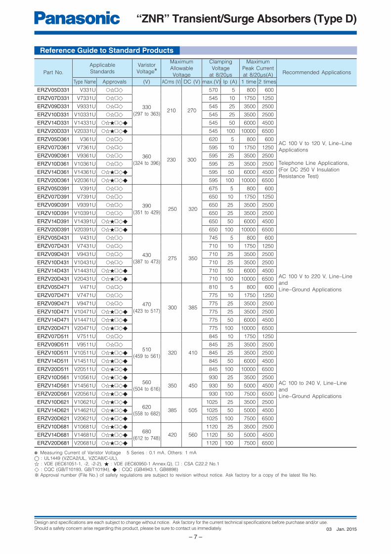
Reference Guide to Standard Products
✽ Measuring Current of Varistor Voltage 5 Series : 0.1 mA, Others: 1 mA
◯ : UL1449 (VZCA2/UL, VZCA8/C-UL),
☆ : VDE (IEC61051-1, -2, -2-2), ★ : VDE (IEC60950-1 Annex.Q), □ : CSA C22.2 No.1
◇ : CQC (GB/T10193, GB/T10194), ◆ : CQC (GB4943.1, GB8898)
※ Approval number (File No.) of safety regulations are subject to revision without notice. Ask factory for a copy of the latest file No.
Part No.
Applicable
Standards
Varistor
Voltage✽
Maximum
Allowable
Voltage
Clamping
Voltage
at 8/20μs
Maximum
Peak Current
at 8/20μs(A) Recommended Applications
Type Name Approvals (V) ACrms (V) DC (V) max.(V) Ip (A) 1 time 2 times
ERZV05D180 V180 ◇
18
(16 to 20)11 14
40 1 250 125
For the low voltage circuit
ERZV07D180 V7180 ◇ 36 2.5 500 250
ERZV09D180 V9180 ◇ 36 5 1000 500
ERZV10D180 V10180 ◇ 36 5 1000 500
ERZV14D180 V14180 ◇ 36 10 2000 1000
ERZV20D180 V20180 ◇ 36 20 3000 2000
ERZV05D220 V220 ◇
22
(20 to 24)14 18
48 1 250 125
ERZV07D220 V7220 ◇ 43 2.5 500 250
ERZV09D220 V9220 ◇ 43 5 1000 500
ERZV10D220 V10220 ◇ 43 5 1000 500
ERZV14D220 V14220 ◇ 43 10 2000 1000
ERZV20D220 V20220 ◇ 43 20 3000 2000
ERZV05D270 V270 ◇
27
(24 to 30)17 22
60 1 250 125
ERZV07D270 V7270 ◇ 53 2.5 500 250
ERZV09D270 V9270 ◇ 53 5 1000 500
ERZV10D270 V10270 ◇ 53 5 1000 500
ERZV14D270 V14270 ◇ 53 10 2000 1000
ERZV20D270 V20270 ◇ 53 20 3000 2000
ERZV05D330 V330 ◇
33
(30 to 36)20 26
73 1 250 125
ERZV07D330 V7330 ◇ 65 2.5 500 250
ERZV09D330 V9330 ◇ 65 5 1000 500
ERZV10D330 V10330 ◇ 65 5 1000 500
ERZV14D330 V14330 ◇ 65 10 2000 1000
ERZV20D330 V20330 ◇ 65 20 3000 2000
ERZV05D390 V390 ◇
39
(35 to 43)25 31
86 1 250 125
ERZV07D390 V7390 ◇ 77 2.5 500 250
ERZV09D390 V9390 ◇ 77 5 1000 500
ERZV10D390 V10390 ◇ 77 5 1000 500
ERZV14D390 V14390 ◇ 77 10 2000 1000
ERZV20D390 V20390 ◇ 77 20 3000 2000
ERZV05D470 V470 ◇
47
(42 to 52)30 38
104 1 250 125
ERZV07D470 V7470 ◇ 93 2.5 500 250
ERZV09D470 V9470 ◇ 93 5 1000 500
ERZV10D470 V10470 ◇ 93 5 1000 500
ERZV14D470 V14470 ◇ 93 10 2000 1000
ERZV20D470 V20470 ◇ 93 20 3000 2000
ERZV05D560 V560 ◇
56
(50 to 62)35 45
123 1 250 125
ERZV07D560 V7560 ◇ 110 2.5 500 250
ERZV09D560 V9560 ◇ 110 5 1000 500
ERZV10D560 V10560 ◇ 110 5 1000 500
ERZV14D560 V14560 ◇ 110 10 2000 1000
ERZV20D560 V20560 ◇ 110 20 3000 2000
ERZV05D680 V680 ◇
68
(61 to 75)40 56
150 1 250 125
ERZV07D680 V7680 ◇ 135 2.5 500 250
ERZV09D680 V9680 ◇ 135 5 1000 500
ERZV10D680 V10680 ◇ 135 5 1000 500
ERZV14D680 V14680 ◇ 135 10 2000 1000
ERZV20D680 V20680 ◇ 135 20 3000 2000
Jan. 201503

Design and specifications are each subject to change without notice. Ask factory for the current technical specifications before purchase and/or use.
Should a safety concern arise regarding this product, please be sure to contact us immediately.
“ZNR” Transient/Surge Absorbers (Type D)
– 6 –
Part No.
Applicable
Standards
Varistor
Voltage✽
Maximum
Allowable
Voltage
Clamping
Voltage
at 8/20μs
Maximum
Peak Current
at 8/20μs(A) Recommended Applications
Type Name Approvals (V) ACrms (V) DC (V) max.(V) Ip (A) 1 time 2 times
ERZV05D820 V820U ○☆◇
82
(74 to 90)50 65
145 5 800 600
Telephone, Communication Line
(DC 48 V)
ERZV07D820 V7820U ○☆◇ 135 10 1750 1250
ERZV09D820 V9820U ○☆◇ 135 25 3500 2500
ERZV10D820 V10820U ○☆◇ 135 25 3500 2500
ERZV14D820 V14820U ○☆◇ 135 50 6000 5000
ERZV20D820 V20820U ○☆◇ 135 100 10000 7000
ERZV05D101 V101U ○☆◇
100
(90 to 110)60 85
175 5 800 600
ERZV07D101 V7101U ○☆◇ 165 10 1750 1250
ERZV09D101 V9101U ○☆◇ 165 25 3500 2500
ERZV10D101 V10101U ○☆◇ 165 25 3500 2500
ERZV14D101 V14101U ○☆◇ 165 50 6000 5000
ERZV20D101 V20101U ○☆◇ 165 100 10000 7000
ERZV05D121 V121U ○☆◇
120
(108 to 132)75 100
210 5 800 600
ERZV07D121 V7121U ○☆◇ 200 10 1750 1250
ERZV09D121 V9121U ○☆◇ 200 25 3500 2500
ERZV10D121 V10121U ○☆◇ 200 25 3500 2500
ERZV14D121 V14121U ○☆◇ 200 50 6000 5000
ERZV20D121 V20121U ○☆◇ 200 100 10000 7000
ERZV05D151 V151U ○☆◇
150
(135 to 165)95 125
260 5 800 600
ERZV07D151 V7151U ○☆◇ 250 10 1750 1250
ERZV09D151 V9151U ○☆◇ 250 25 3500 2500
ERZV10D151 V10151U ○☆◇ 250 25 3500 2500
ERZV14D151 V14151U ○☆◇ 250 50 6000 5000
ERZV20D151 V20151U ○☆◇ 250 100 10000 7000
ERZV05D201 V201U ○☆□◇
200
(185 to 225)130 170
355 5 800 600
AC 100 V Line–Line
Applications
ERZV07D201 V7201U ○☆□◇ 340 10 1750 1250
ERZV09D201 V9201U ○☆□◇ 340 25 3500 2500
ERZV10D201 V10201U ○☆□◇ 340 25 3500 2500
ERZV14D201 V14201U ○☆★□◇◆ 340 50 6000 5000
ERZV20D201 V20201U ○☆★□◇◆ 340 100 10000 7000
ERZV05D221 V221U ○☆□◇
220
(198 to 242)140 180
380 5 800 600
ERZV07D221 V7221U ○☆□◇ 360 10 1750 1250
ERZV09D221 V9221U ○☆□◇ 360 25 3500 2500
ERZV10D221 V10221U ○☆□◇ 360 25 3500 2500
ERZV14D221 V14221U ○☆★□◇◆ 360 50 6000 5000
ERZV20D221 V20221U ○☆★□◇◆ 360 100 10000 7000
ERZV05D241 V241U ○☆□◇
240
(216 to 264)150 200
415 5 800 600
AC 100 V to 120 V, Line–Line
Applications
ERZV07D241 V7241U ○☆□◇ 395 10 1750 1250
ERZV09D241 V9241U ○☆□◇ 395 25 3500 2500
ERZV10D241 V10241U ○☆□◇ 395 25 3500 2500
ERZV14D241 V14241U ○☆★□◇◆ 395 50 6000 5000
ERZV20D241 V20241U ○☆★□◇◆ 395 100 10000 7000
ERZV05D271 V271U ○☆□◇
270
(247 to 303)175 225
475 5 800 600
ERZV07D271 V7271U ○☆□◇ 455 10 1750 1250
ERZV09D271 V9271U ○☆□◇ 455 25 3500 2500
ERZV10D271 V10271U ○☆□◇ 455 25 3500 2500
ERZV14D271 V14271U ○☆★□◇◆ 455 50 6000 5000
ERZV20D271 V20271U ○☆★□◇◆ 455 100 10000 7000
✽ Measuring Current of Varistor Voltage 5 Series : 0.1 mA, Others: 1 mA
◯ : UL1449 (VZCA2/UL, VZCA8/C-UL),
☆ : VDE (IEC61051-1, -2, -2-2), ★ : VDE (IEC60950-1 Annex.Q), □ : CSA C22.2 No.1
◇ : CQC (GB/T10193, GB/T10194), ◆ : CQC (GB4943.1, GB8898)
※ Approval number (File No.) of safety regulations are subject to revision without notice. Ask factory for a copy of the latest file No.
Reference Guide to Standard Products
Jan. 201503
Design and specifications are each subject to change without notice. Ask factory for the current technical specifications before purchase and/or use.
Should a safety concern arise regarding this product, please be sure to contact us immediately.
“ZNR” Transient/Surge Absorbers (Type D)
– 7 –
Part No.
Applicable
Standards
Varistor
Voltage✽
Maximum
Allowable
Voltage
Clamping
Voltage
at 8/20μs
Maximum
Peak Current
at 8/20μs(A) Recommended Applications
Type Name Approvals (V) ACrms (V) DC (V) max.(V) Ip (A) 1 time 2 times
ERZV05D331 V331U ○☆□◇
330
(297 to 363)210 270
570 5 800 600
AC 100 V to 120 V, Line–Line
Applications
Telephone Line Applications,
(For DC 250 V Insulation
Resistance Test)
ERZV07D331 V7331U ○☆□◇ 545 10 1750 1250
ERZV09D331 V9331U ○☆□◇ 545 25 3500 2500
ERZV10D331 V10331U ○☆□◇ 545 25 3500 2500
ERZV14D331 V14331U ○☆★□◇◆ 545 50 6000 4500
ERZV20D331 V20331U ○☆★□◇◆ 545 100 10000 6500
ERZV05D361 V361U ○☆□◇
360
(324 to 396)230 300
620 5 800 600
ERZV07D361 V7361U ○☆□◇ 595 10 1750 1250
ERZV09D361 V9361U ○☆□◇ 595 25 3500 2500
ERZV10D361 V10361U ○☆□◇ 595 25 3500 2500
ERZV14D361 V14361U ○☆★□◇◆ 595 50 6000 4500
ERZV20D361 V20361U ○☆★□◇◆ 595 100 10000 6500
ERZV05D391 V391U ○☆□◇
390
(351 to 429)250 320
675 5 800 600
ERZV07D391 V7391U ○☆□◇ 650 10 1750 1250
ERZV09D391 V9391U ○☆□◇ 650 25 3500 2500
ERZV10D391 V10391U ○☆□◇ 650 25 3500 2500
ERZV14D391 V14391U ○☆★□◇◆ 650 50 6000 4500
ERZV20D391 V20391U ○☆★□◇◆ 650 100 10000 6500
ERZV05D431 V431U ○☆□◇
430
(387 to 473)275 350
745 5 800 600
AC 100 V to 220 V, Line–Line
and
Line–Ground Applications
ERZV07D431 V7431U ○☆□◇ 710 10 1750 1250
ERZV09D431 V9431U ○☆□◇ 710 25 3500 2500
ERZV10D431 V10431U ○☆□◇ 710 25 3500 2500
ERZV14D431 V14431U ○☆★□◇◆ 710 50 6000 4500
ERZV20D431 V20431U ○☆★□◇◆ 710 100 10000 6500
ERZV05D471 V471U ○☆□◇
470
(423 to 517)300 385
810 5 800 600
ERZV07D471 V7471U ○☆□◇ 775 10 1750 1250
ERZV09D471 V9471U ○☆□◇ 775 25 3500 2500
ERZV10D471 V10471U ○☆★□◇◆ 775 25 3500 2500
ERZV14D471 V14471U ○☆★□◇◆ 775 50 6000 4500
ERZV20D471 V20471U ○☆★□◇◆ 775 100 10000 6500
ERZV07D511 V7511U ○☆□◇
510
(459 to 561)320 410
845 10 1750 1250
AC 100 to 240 V, Line–Line
and
Line–Ground Applications
ERZV09D511 V9511U ○☆□◇ 845 25 3500 2500
ERZV10D511 V10511U ○☆★□◇◆ 845 25 3500 2500
ERZV14D511 V14511U ○☆★□◇◆ 845 50 6000 4500
ERZV20D511 V20511U ○☆★□◇◆ 845 100 10000 6500
ERZV10D561 V10561U ○☆★□◇◆560
(504 to 616)350 450
930 25 3500 2500
ERZV14D561 V14561U ○☆★□◇◆ 930 50 5000 4500
ERZV20D561 V20561U ○☆★□◇◆ 930 100 7500 6500
ERZV10D621 V10621U ○☆★□◇◆620
(558 to 682)385 505
1025 25 3500 2500
ERZV14D621 V14621U ○☆★□◇◆ 1025 50 5000 4500
ERZV20D621 V20621U ○☆★□◇◆ 1025 100 7500 6500
ERZV10D681 V10681U ○☆★□◇◆680
(612 to 748)420 560
1120 25 3500 2500
ERZV14D681 V14681U ○☆★□◇◆ 1120 50 5000 4500
ERZV20D681 V20681U ○☆★□◇◆ 1120 100 7500 6500
✽ Measuring Current of Varistor Voltage 5 Series : 0.1 mA, Others: 1 mA
◯ : UL1449 (VZCA2/UL, VZCA8/C-UL),
☆ : VDE (IEC61051-1, -2, -2-2), ★ : VDE (IEC60950-1 Annex.Q), □ : CSA C22.2 No.1
◇ : CQC (GB/T10193, GB/T10194), ◆ : CQC (GB4943.1, GB8898)
※ Approval number (File No.) of safety regulations are subject to revision without notice. Ask factory for a copy of the latest file No.
Reference Guide to Standard Products
Jan. 201503

Design and specifications are each subject to change without notice. Ask factory for the current technical specifications before purchase and/or use.
Should a safety concern arise regarding this product, please be sure to contact us immediately.
“ZNR” Transient/Surge Absorbers (Type D)
– 8 –
Reference Guide to Standard Products
Part No.
Applicable
Standards
Varistor
Voltage✽
Maximum
Allowable
Voltage
Clamping
Voltage
at 8/20μs
Maximum
Peak Current
at 8/20μs(A) Recommended Applications
Type Name Approvals (V) ACrms (V) DC (V) max.(V) Ip (A) 1 time 2 times
ERZV10D751 V10751U ○☆★□◇◆750
(675 to 825)460 615
1240 25 3500 2500
AC 380 V, Line–Line and
Line–Ground Applications
(For DC 500 V Insulating Test)
ERZV14D751 V14751U ○☆★□◇◆ 1240 50 5000 4500
ERZV20D751 V20751U ○☆★□◇◆ 1240 100 7500 6500
ERZV10D821 V10821U ○☆★□◇◆820
(738 to 902)510 670
1355 25 3500 2500
ERZV14D821 V14821U ○☆★□◇◆ 1355 50 5000 4500
ERZV20D821 V20821U ○☆★□◇◆ 1355 100 7500 6500
ERZV10D911 V10911U ○☆★□◇◆910
(819 to 1001)550 745
1500 25 3500 2500 AC 415 V, Line–Line and
Line–Ground Applications
(For DC 500 V Insulating Test)
ERZV14D911 V14911U ○☆★□◇◆ 1500 50 5000 4500
ERZV20D911 V20911U ○☆★□◇◆ 1500 100 7500 6500
ERZV10D102 V10102U ○☆★□◇◆1000
(900 to 1100)625 825
1650 25 3500 2500
AC 480 V, Line–Line and
Line–Ground Applications
(For DC 500 V Insulating Test)
ERZV14D102 V14102U ○☆★□◇◆ 1650 50 5000 4500
ERZV20D102 V20102U ○☆★□◇◆ 1650 100 7500 6500
ERZV10D112 V10112U ○☆★□◇◆1100
(990 to 1210)680 895
1815 25 3500 2500
ERZV14D112 V14112U ○☆★□◇◆ 1815 50 5000 4500
ERZV20D112 V20112U ○☆★□◇◆ 1815 100 7500 6500
ERZV10D182CS V10182U ○☆★□◇◆1800
(1700 to 1980)1000 1465
2970 25 3500 2500 Line–Ground Applications
(For AC 1200 V Withstanding
Test)
ERZV14D182CS V14182U ○☆★□◇◆ 2970 50 5000 4500
ERZV20D182 V20182U ○☆★□◇◆ 2970 100 7500 6500
✽ Measuring Current of Varistor Voltage 5 Series : 0.1 mA, Others: 1 mA
◯ : UL1449 (VZCA2/UL, VZCA8/C-UL),
☆ : VDE (IEC61051-1, -2, -2-2), ★ : VDE (IEC60950-1 Annex.Q), □ : CSA C22.2 No.1
◇ : CQC (GB/T10193, GB/T10194), ◆ : CQC (GB4943.1, GB8898)
※ Approval number (File No.) of safety regulations are subject to revision without notice. Ask factory for a copy of the latest file No.
Jan. 201503
Design and specifications are each subject to change without notice. Ask factory for the current technical specifications before purchase and/or use.
Should a safety concern arise regarding this product, please be sure to contact us immediately.
“ZNR” Transient/Surge Absorbers (Type D)
– 9 –
DT
W
W
H20.0
min
.
f0.6
L
L
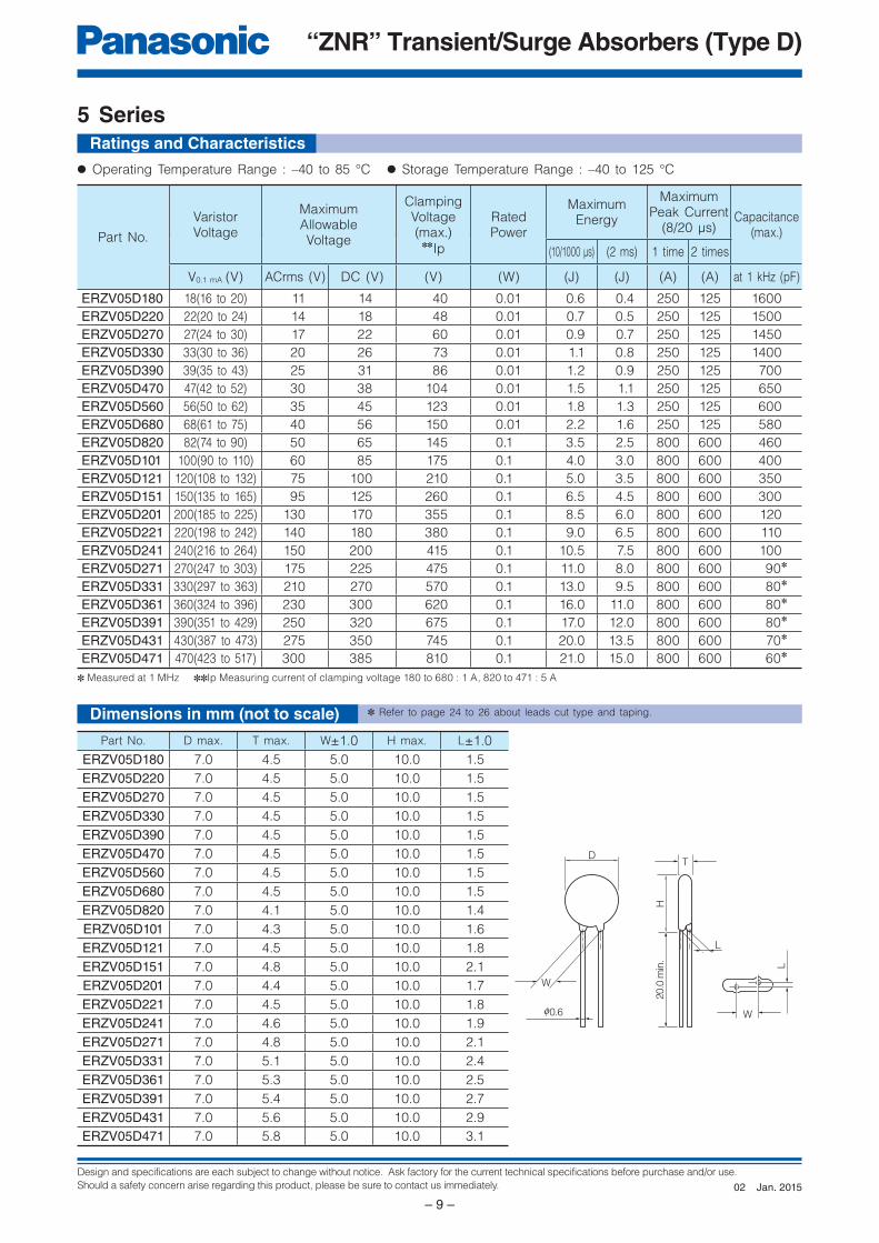
● Operating Temperature Range : –40 to 85 °C ● Storage Temperature Range : –40 to 125 °C
Ratings and Characteristics
5 Series
Part No.
VaristorVoltage
MaximumAllowableVoltage
ClampingVoltage(max.)
✽✽Ip
RatedPower
MaximumEnergy
MaximumPeak Current
(8/20 μs)Capacitance
(max.)
(10/1000 μs) (2 ms) 1 time 2 times
V0.1 mA (V) ACrms (V) DC (V) (V) (W) (J) (J) (A) (A) at 1 kHz (pF)
ERZV05D180 18(16 to 20) 11 14 40 0.01 0.6 0.4 250 125 1600
ERZV05D220 22(20 to 24) 14 18 48 0.01 0.7 0.5 250 125 1500
ERZV05D270 27(24 to 30) 17 22 60 0.01 0.9 0.7 250 125 1450
ERZV05D330 33(30 to 36) 20 26 73 0.01 1.1 0.8 250 125 1400
ERZV05D390 39(35 to 43) 25 31 86 0.01 1.2 0.9 250 125 700
ERZV05D470 47(42 to 52) 30 38 104 0.01 1.5 1.1 250 125 650
ERZV05D560 56(50 to 62) 35 45 123 0.01 1.8 1.3 250 125 600
ERZV05D680 68(61 to 75) 40 56 150 0.01 2.2 1.6 250 125 580
ERZV05D820 82(74 to 90) 50 65 145 0.1 3.5 2.5 800 600 460
ERZV05D101 100(90 to 110) 60 85 175 0.1 4.0 3.0 800 600 400
ERZV05D121 120(108 to 132) 75 100 210 0.1 5.0 3.5 800 600 350
ERZV05D151 150(135 to 165) 95 125 260 0.1 6.5 4.5 800 600 300
ERZV05D201 200(185 to 225) 130 170 355 0.1 8.5 6.0 800 600 120
ERZV05D221 220(198 to 242) 140 180 380 0.1 9.0 6.5 800 600 110
ERZV05D241 240(216 to 264) 150 200 415 0.1 10.5 7.5 800 600 100
ERZV05D271 270(247 to 303) 175 225 475 0.1 11.0 8.0 800 600 90✽
ERZV05D331 330(297 to 363) 210 270 570 0.1 13.0 9.5 800 600 80✽
ERZV05D361 360(324 to 396) 230 300 620 0.1 16.0 11.0 800 600 80✽
ERZV05D391 390(351 to 429) 250 320 675 0.1 17.0 12.0 800 600 80✽
ERZV05D431 430(387 to 473) 275 350 745 0.1 20.0 13.5 800 600 70✽
ERZV05D471 470(423 to 517) 300 385 810 0.1 21.0 15.0 800 600 60✽
✽ Measured at 1 MHz ✽✽Ip Measuring current of clamping voltage 180 to 680 : 1 A, 820 to 471 : 5 A
Part No. D max. T max. W±1.0 H max. L±1.0
ERZV05D180 7.0 4.5 5.0 10.0 1.5
ERZV05D220 7.0 4.5 5.0 10.0 1.5
ERZV05D270 7.0 4.5 5.0 10.0 1.5
ERZV05D330 7.0 4.5 5.0 10.0 1.5
ERZV05D390 7.0 4.5 5.0 10.0 1.5
ERZV05D470 7.0 4.5 5.0 10.0 1.5
ERZV05D560 7.0 4.5 5.0 10.0 1.5
ERZV05D680 7.0 4.5 5.0 10.0 1.5
ERZV05D820 7.0 4.1 5.0 10.0 1.4
ERZV05D101 7.0 4.3 5.0 10.0 1.6
ERZV05D121 7.0 4.5 5.0 10.0 1.8
ERZV05D151 7.0 4.8 5.0 10.0 2.1
ERZV05D201 7.0 4.4 5.0 10.0 1.7
ERZV05D221 7.0 4.5 5.0 10.0 1.8
ERZV05D241 7.0 4.6 5.0 10.0 1.9
ERZV05D271 7.0 4.8 5.0 10.0 2.1
ERZV05D331 7.0 5.1 5.0 10.0 2.4
ERZV05D361 7.0 5.3 5.0 10.0 2.5
ERZV05D391 7.0 5.4 5.0 10.0 2.7
ERZV05D431 7.0 5.6 5.0 10.0 2.9
ERZV05D471 7.0 5.8 5.0 10.0 3.1
Dimensions in mm (not to scale) ✽ Refer to page 24 to 26 about leads cut type and taping.
Jan. 201502
Design and specifications are each subject to change without notice. Ask factory for the current technical specifications before purchase and/or use.
Should a safety concern arise regarding this product, please be sure to contact us immediately.
“ZNR” Transient/Surge Absorbers (Type D)
– 10 –
Impulse Width (μs)
Imp
uls
e C
urr
en
t (A
)
1000
100
10
1
0.120 100 1000 10000
10 2 Times
1 Time
2 Times
10 Times
10 3 Times
10 4 Times
10 5 Times
10 6 Times
5 min. interval
2 min. interval
10 sec. interval
2 times :
up to 10 times :
up to 106 times :
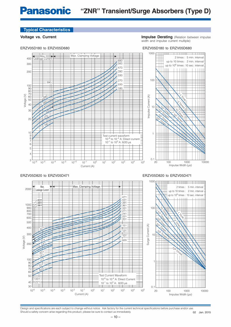
400
300
200
1009080706050
40
30
76
3
20
1098
Voltag
e (
V)
10–6 10–5 10–4 10–3 10–2 10–1 100 101 102 103 104 105
Current (A)
390
270
220
180
330
470560
680
680560
470
390
330
270
220
180
5
4
Test current waveform
10–6 to 10–4 A: Direct current
10–1 to 103 A: 8/20 μs
Max. Clamping VoltageMax.Leakage Current
30
40
50
60708090
100
200
300
400
500
600
700800900
1000
2000
10-6 10-5 10-4 10-3 10-2 10-1 100 101 102 103 104 105
Voltag
e (
V)
Current (A)
471
271
201
151
121
101
820
471431391361331271241221201
151
121
101
820
241
Test Current Waveform
10-6 to 10-4 A: Direct Current
10-1 to 103 A: 8/20 μs
Max. Clamping VoltageMax.
Leakage Current
431391361
221
331
Impulse Width (μs)
Surg
e C
urr
ent (A
)
1000
100
10
1
20 100 1000 10000
0.1
1 Time
2 Times
10 Times
10 2 Tim
es
10 3 Tim
es10 4 Tim
es10 5 Times
10 6 Times
5 min. interval
2 min. interval
10 sec. interval
2 times :
up to 10 times :
up to 106 times :
Typical Characteristics
ERZV05D820 to ERZV05D471
ERZV05D180 to ERZV05D680
ERZV05D820 to ERZV05D471
ERZV05D180 to ERZV05D680
Voltage vs. Current Impulse Derating (Relation between impulse width and impulse current multiple)
Jan. 201502

Design and specifications are each subject to change without notice. Ask factory for the current technical specifications before purchase and/or use.
Should a safety concern arise regarding this product, please be sure to contact us immediately.
“ZNR” Transient/Surge Absorbers (Type D)
– 11 –
DT
W
W
H20.0
min
.
f 0.6
L
L
● Operating Temperature Range : –40 to 85 °C ● Storage Temperature Range : –40 to 125 °C
Ratings and Characteristics
7 Series
✽ Measured at 1 MHz ✽✽Ip Measuring current of clamping voltage 180 to 680 : 25 A, 820 to 511 : 10 A
Dimensions in mm (not to scale) ✽ Refer to page 24 to 26 about leads cut type and taping.
Part No.
VaristorVoltage
MaximumAllowableVoltage
ClampingVoltage(max.)
✽✽Ip
RatedPower
MaximumEnergy
MaximumPeak Current
(8/20 μs)Capacitance
(max.)
(10/1000 μs) (2 ms) 1 time 2 times
V1 mA (V) ACrms (V) DC (V) (V) (W) (J) (J) (A) (A) at 1 kHz (pF)
ERZV07D180 18(16 to 20) 11 14 36 0.02 1.1 0.9 500 250 3800
ERZV07D220 22(20 to 24) 14 18 43 0.02 1.3 1.1 500 250 3600
ERZV07D270 27(24 to 30) 17 22 53 0.02 1.6 1.3 500 250 3400
ERZV07D330 33(30 to 36) 20 26 65 0.02 2.0 1.6 500 250 2900
ERZV07D390 39(35 to 43) 25 31 77 0.02 2.4 1.9 500 250 1600
ERZV07D470 47(42 to 52) 30 38 93 0.02 2.8 2.3 500 250 1550
ERZV07D560 56(50 to 62) 35 45 110 0.02 3.4 2.7 500 250 1500
ERZV07D680 68(61 to 75) 40 56 135 0.02 4.1 3.3 500 250 1200
ERZV07D820 82(74 to 90) 50 65 135 0.25 7 5 1750 1250 810
ERZV07D101 100(90 to 110) 60 85 165 0.25 8.5 6 1750 1250 700
ERZV07D121 120(108 to 132) 75 100 200 0.25 10 7 1750 1250 590
ERZV07D151 150(135 to 165) 95 125 250 0.25 13 9 1750 1250 500
ERZV07D201 200(185 to 225) 130 170 340 0.25 17.5 12.5 1750 1250 200
ERZV07D221 220(198 to 242) 140 180 360 0.25 19 13.5 1750 1250 190
ERZV07D241 240(216 to 264) 150 200 395 0.25 21 15 1750 1250 170
ERZV07D271 270(247 to 303) 175 225 455 0.25 24 17 1750 1250 150
ERZV07D331 330(297 to 363) 210 270 545 0.25 28 20 1750 1250 130
ERZV07D361 360(324 to 396) 230 300 595 0.25 32 23 1750 1250 130
ERZV07D391 390(351 to 429) 250 320 650 0.25 35 25 1750 1250 130
ERZV07D431 430(387 to 473) 275 350 710 0.25 40 27.5 1750 1250 120
ERZV07D471 470(423 to 517) 300 385 775 0.25 42 30 1750 1250 100
ERZV07D511 510(459 to 561) 320 410 845 0.25 45 32 1750 1250 90✽
Part No. D max. T max. W±1.0 H max. L±1.0
ERZV07D180 8.5 4.5 5.0 11.5 1.3
ERZV07D220 8.5 4.6 5.0 11.5 1.4
ERZV07D270 8.5 4.7 5.0 11.5 1.5
ERZV07D330 8.5 4.9 5.0 11.5 1.7
ERZV07D390 8.5 4.8 5.0 11.5 1.6
ERZV07D470 8.5 4.9 5.0 11.5 1.7
ERZV07D560 8.5 5.0 5.0 11.5 1.8
ERZV07D680 8.5 5.2 5.0 11.5 2.0
ERZV07D820 8.5 4.1 5.0 11.5 1.4
ERZV07D101 8.5 4.3 5.0 11.5 1.6
ERZV07D121 8.5 4.5 5.0 11.5 1.8
ERZV07D151 8.5 4.8 5.0 11.5 2.1
ERZV07D201 8.5 4.4 5.0 11.5 1.7
ERZV07D221 8.5 4.5 5.0 11.5 1.8
ERZV07D241 8.5 4.6 5.0 11.5 1.9
ERZV07D271 8.5 4.8 5.0 11.5 2.1
ERZV07D331 8.5 5.1 5.0 11.5 2.4
ERZV07D361 8.5 5.3 5.0 11.5 2.5
ERZV07D391 8.5 5.4 5.0 11.5 2.7
ERZV07D431 8.5 5.6 5.0 11.5 2.9
ERZV07D471 8.5 5.8 5.0 11.5 3.1
ERZV07D511 8.5 6.0 5.0 11.5 3.3
Jan. 201502

Design and specifications are each subject to change without notice. Ask factory for the current technical specifications before purchase and/or use.
Should a safety concern arise regarding this product, please be sure to contact us immediately.
“ZNR” Transient/Surge Absorbers (Type D)
– 12 –
400
300
200
1009080706050
40
30
76
3
20
1098
Voltag
e (
V)
10–6 10–5 10–4 10–3 10–2 10–1 100 101 102 103 104 105
Current (A)
680
560
470
390
330
270
220
180
680560
470
390
330
270
220
180
4
5
Test current waveform
10–6 to 10–3 A: Direct current
10–1 to 103 A: 8/20 μs
Max.Leakage Current
Max. Clamping Voltage
Impulse Width (μs)
Imp
uls
e C
urr
en
t (A
)
1000
100
10
1
0.1
20 100 1000 10000
1 Time2 Tim
es
10 Times
10 2 Tim
es
10 3 Times
10 4 Times10 5 Tim
es10 6 Times
5 min. interval
2 min. interval
10 sec. interval
2 times :
up to 10 times :
up to 106 times :
30
40
50
60708090
100
200
300
400
500
600
700800900
1000
2000
10-6 10-5 10-4 10-3 10-2 10-1 100 101 102 103 104 105
Voltag
e (
V)
Current (A)
241
511
151
121
101
820
201
271
151
121
101
820
511471431391361331271241221201
Test Current Waveform
10-6 to 10-3 A: Direct Current
10-1 to 104 A: 8/20 μs
Max. Clamping VoltageMax.
Leakage Current
471431391361
221331
Impulse Width (μs)
Surg
e C
urr
ent (A
)
10000
1000
100
10
20 100 1000 10000
1
1 Time
2 Times
10 Times
10 2 Tim
es
10 3 Tim
es
10 4 Times
10 5 Times
10 6 Times
5 min. interval
2 min. interval
10 sec. interval
2 times :
up to 10 times :
up to 106 times :
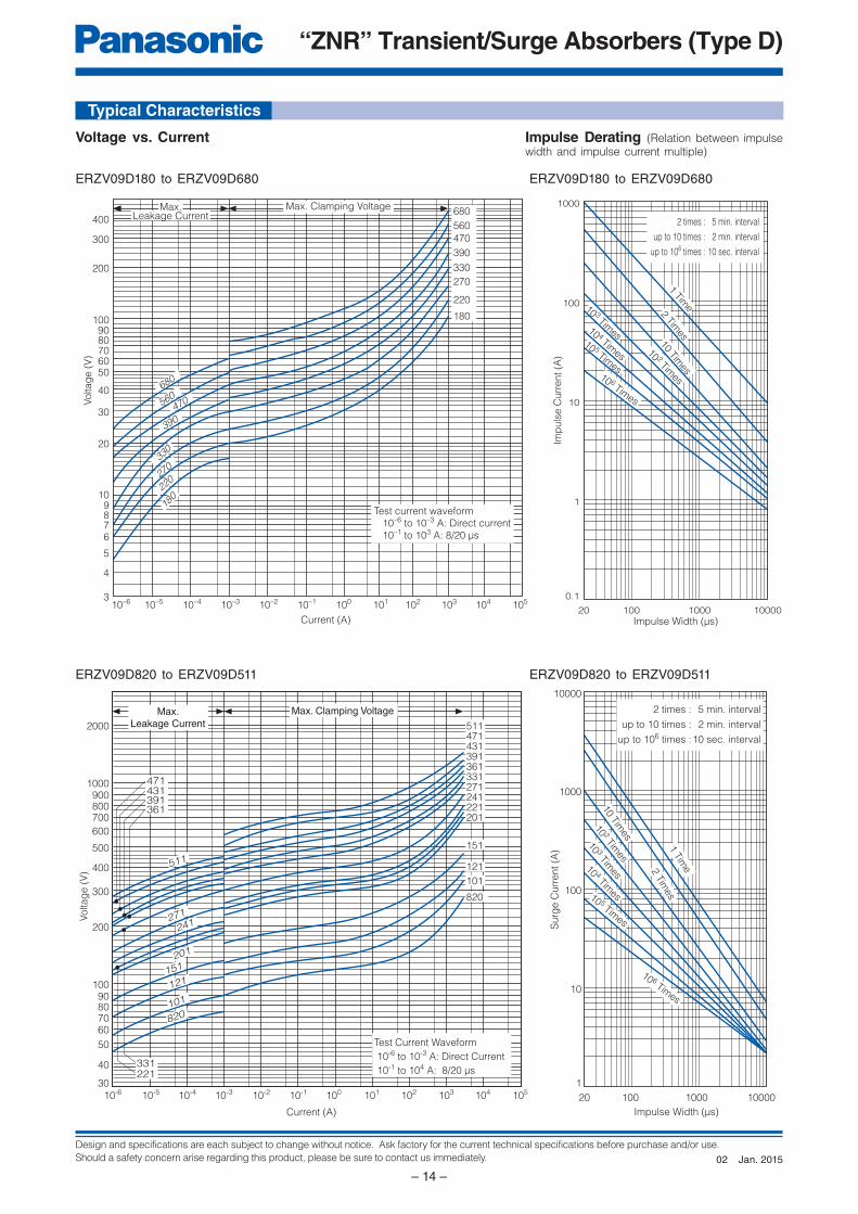
Typical Characteristics
Voltage vs. Current Impulse Derating (Relation between impulse width and impulse current multiple)
ERZV07D820 to ERZV07D511
ERZV07D180 to ERZV07D680
ERZV07D820 to ERZV07D511
ERZV07D180 to ERZV07D680
Jan. 201502

Design and specifications are each subject to change without notice. Ask factory for the current technical specifications before purchase and/or use.
Should a safety concern arise regarding this product, please be sure to contact us immediately.
“ZNR” Transient/Surge Absorbers (Type D)
– 13 –
DT
W
W
H20.0
min
.
f 0.6
L
L
● Operating Temperature Range : –40 to 85 °C ● Storage Temperature Range : –40 to 125 °C
Ratings and Characteristics
9 Series
✽Ip Measuring current of clamping voltage 180 to 680 : 5 A, 820 to 511 : 25 A
Dimensions in mm (not to scale) ✽ Refer to page 24 to 26 about leads cut type and taping.
Part No.
VaristorVoltage
MaximumAllowableVoltage
ClampingVoltage(max.)
✽Ip
RatedPower
MaximumEnergy
MaximumPeak Current
(8/20 μs)Capacitance
(max.)
(10/1000 μs) (2 ms) 1 time 2 times
V1 mA (V) ACrms (V) DC (V) (V) (W) (J) (J) (A) (A) at 1 kHz (pF)
ERZV09D180 18(16 to 20) 11 14 36 0.05 2.6 2.2 1000 500 16000
ERZV09D220 22(20 to 24) 14 18 43 0.05 3.2 2.6 1000 500 11000
ERZV09D270 27(24 to 30) 17 22 53 0.05 3.9 3.2 1000 500 8000
ERZV09D330 33(30 to 36) 20 26 65 0.05 4.8 4.0 1000 500 6300
ERZV09D390 39(35 to 43) 25 31 77 0.05 5.6 4.7 1000 500 5200
ERZV09D470 47(42 to 52) 30 38 93 0.05 6.8 5.6 1000 500 4600
ERZV09D560 56(50 to 62) 35 45 110 0.05 8.1 6.7 1000 500 3750
ERZV09D680 68(61 to 75) 40 56 135 0.05 9.8 8.2 1000 500 2800
ERZV09D820 82(74 to 90) 50 65 135 0.4 14 10 3500 2500 2000
ERZV09D101 100(90 to 110) 60 85 165 0.4 17 12 3500 2500 1700
ERZV09D121 120(108 to 132) 75 100 200 0.4 20 14.5 3500 2500 1400
ERZV09D151 150(135 to 165) 95 125 250 0.4 25 18 3500 2500 1100
ERZV09D201 200(185 to 225) 130 170 340 0.4 35 25 3500 2500 430
ERZV09D221 220(198 to 242) 140 180 360 0.4 39 27.5 3500 2500 410
ERZV09D241 240(216 to 264) 150 200 395 0.4 42 30 3500 2500 380
ERZV09D271 270(247 to 303) 175 225 455 0.4 49 35 3500 2500 350
ERZV09D331 330(297 to 363) 210 270 545 0.4 58 42 3500 2500 300
ERZV09D361 360(324 to 396) 230 300 595 0.4 65 45 3500 2500 300
ERZV09D391 390(351 to 429) 250 320 650 0.4 70 50 3500 2500 300
ERZV09D431 430(387 to 473) 275 350 710 0.4 80 55 3500 2500 270
ERZV09D471 470(423 to 517) 300 385 775 0.4 85 60 3500 2500 230
ERZV09D511 510(459 to 561) 320 410 845 0.4 92 67 3500 2500 210
Part No. D max. T max. W±1.0 H max. L±1.0
ERZV09D180 11.5 3.8 5.0 14.0 1.3
ERZV09D220 11.5 4.0 5.0 14.0 1.4
ERZV09D270 11.5 4.2 5.0 14.0 1.5
ERZV09D330 11.5 4.5 5.0 14.0 1.7
ERZV09D390 11.5 4.0 5.0 14.0 1.7
ERZV09D470 11.5 4.2 5.0 14.0 1.8
ERZV09D560 11.5 4.4 5.0 14.0 1.9
ERZV09D680 11.5 4.5 5.0 14.0 2.2
ERZV09D820 11.5 3.8 5.0 14.0 1.6
ERZV09D101 11.5 3.9 5.0 14.0 1.8
ERZV09D121 11.5 4.1 5.0 14.0 2.0
ERZV09D151 11.5 4.4 5.0 14.0 2.2
ERZV09D201 11.5 4.1 5.0 14.0 1.7
ERZV09D221 11.5 4.2 5.0 14.0 1.8
ERZV09D241 11.5 4.3 5.0 14.0 1.9
ERZV09D271 11.5 4.5 5.0 14.0 2.0
ERZV09D331 11.5 4.8 5.0 14.0 2.3
ERZV09D361 11.5 5.0 5.0 14.0 2.5
ERZV09D391 11.5 5.1 5.0 14.0 2.6
ERZV09D431 11.5 5.3 5.0 14.0 2.8
ERZV09D471 11.5 5.6 5.0 14.0 3.1
ERZV09D511 11.5 5.8 5.0 14.0 3.2
Jan. 201502
Design and specifications are each subject to change without notice. Ask factory for the current technical specifications before purchase and/or use.
Should a safety concern arise regarding this product, please be sure to contact us immediately.
“ZNR” Transient/Surge Absorbers (Type D)
– 14 –
30
40
50
60708090
100
200
300
400
500
600
700800900
1000
2000 511471431391361331271241221201
511
271
201
151
121
101
820
10-6 10-5 10-4 10-3 10-2 10-1 100 101 102 103 104 105
241
151
121
101
820
Voltag
e (
V)
Test Current Waveform
10-6 to 10-3 A: Direct Current
10-1 to 104 A: 8/20 μs
Current (A)
Max. Clamping VoltageMax.
Leakage Current
221331
471431391361
10000
1000
100
10
20 100 1000 10000
1
1 Time2 Tim
es
10 Times
10 2 Tim
es
10 3 Tim
es
10 4 Tim
es10 5 Times
10 6 Times
Impulse Width (μs)
Surg
e C
urr
ent (A
)
5 min. interval
2 min. interval
10 sec. interval
2 times :
up to 10 times :
up to 106 times :
1000
100
10
1
0.1
20 100 1000 10000
1 Time
2 Times
10 Times
10 2 Tim
es
10 3 Tim
es10 4 Tim
es
10 5 Times
10 6 Times
Impulse Width (μs)
Imp
uls
e C
urr
ent (A
)
5 min. interval
2 min. interval
10 sec. interval
2 times :
up to 10 times :
up to 106 times :
680
560470
270
220
180
390
330
180
680560470390330270
220
400
300
200
1009080706050
40
30
76
5
20
1098
10–6 10–5 10–4 10–3 10–2 10–1 100 101 102 103 104 1053
4
Volta
ge
(V)
Current (A)
Test current waveform 10–6 to 10–3 A: Direct current 10–1 to 103 A: 8/20 μs
Max. Clamping VoltageMax.Leakage Current
Typical Characteristics
Voltage vs. Current Impulse Derating (Relation between impulse width and impulse current multiple)
ERZV09D820 to ERZV09D511
ERZV09D180 to ERZV09D680
ERZV09D820 to ERZV09D511
ERZV09D180 to ERZV09D680
Jan. 201502

Design and specifications are each subject to change without notice. Ask factory for the current technical specifications before purchase and/or use.
Should a safety concern arise regarding this product, please be sure to contact us immediately.
“ZNR” Transient/Surge Absorbers (Type D)
– 15 –
● Operating Temperature Range : –40 to 85 °C ● Storage Temperature Range : –40 to 125 °C
Ratings and Characteristics
10 Series
✽ Measured at 1 MHz ✽✽Ip Measuring current of clamping voltage 180 to 680 : 5 A, 820 to 182 : 25 A
Part No.
VaristorVoltage
MaximumAllowableVoltage
ClampingVoltage(max.)
✽✽Ip
RatedPower
MaximumEnergy
MaximumPeak Current
(8/20 μs)Capacitance
(max.)
(10/1000 μs) (2 ms) 1 time 2 times
V1 mA (V) ACrms (V) DC (V) (V) (W) (J) (J) (A) (A) at 1 kHz (pF)
ERZV10D180 18(16 to 20) 11 14 36 0.05 2.6 2.2 1000 500 16000
ERZV10D220 22(20 to 24) 14 18 43 0.05 3.2 2.6 1000 500 11000
ERZV10D270 27(24 to 30) 17 22 53 0.05 3.9 3.2 1000 500 8000
ERZV10D330 33(30 to 36) 20 26 65 0.05 4.8 4.0 1000 500 6300
ERZV10D390 39(35 to 43) 25 31 77 0.05 5.6 4.7 1000 500 5200
ERZV10D470 47(42 to 52) 30 38 93 0.05 6.8 5.6 1000 500 4600
ERZV10D560 56(50 to 62) 35 45 110 0.05 8.1 6.7 1000 500 3750
ERZV10D680 68(61 to 75) 40 56 135 0.05 9.8 8.2 1000 500 2800
ERZV10D820 82(74 to 90) 50 65 135 0.4 14 10 3500 2500 2000
ERZV10D101 100(90 to 110) 60 85 165 0.4 17 12 3500 2500 1700
ERZV10D121 120(108 to 132) 75 100 200 0.4 20 14.5 3500 2500 1400
ERZV10D151 150(135 to 165) 95 125 250 0.4 25 18 3500 2500 1100
ERZV10D201 200(185 to 225) 130 170 340 0.4 35 25 3500 2500 430
ERZV10D221 220(198 to 242) 140 180 360 0.4 39 27.5 3500 2500 410
ERZV10D241 240(216 to 264) 150 200 395 0.4 42 30 3500 2500 380
ERZV10D271 270(247 to 303) 175 225 455 0.4 49 35 3500 2500 350
ERZV10D331 330(297 to 363) 210 270 545 0.4 58 42 3500 2500 300
ERZV10D361 360(324 to 396) 230 300 595 0.4 65 45 3500 2500 300
ERZV10D391 390(351 to 429) 250 320 650 0.4 70 50 3500 2500 300
ERZV10D431 430(387 to 473) 275 350 710 0.4 80 55 3500 2500 270
ERZV10D471 470(423 to 517) 300 385 775 0.4 85 60 3500 2500 230
ERZV10D511 510(459 to 561) 320 410 845 0.4 92 67 3500 2500 210
ERZV10D561 560(504 to 616) 350 450 930 0.4 92 67 3500 2500 200
ERZV10D621 620(558 to 682) 385 505 1025 0.4 92 67 3500 2500 190
ERZV10D681 680(612 to 748) 420 560 1120 0.4 92 67 3500 2500 170
ERZV10D751 750(675 to 825) 460 615 1240 0.4 100 70 3500 2500 160
ERZV10D821 820(738 to 902) 510 670 1355 0.4 110 80 3500 2500 140
ERZV10D911 910(819 to 1001) 550 745 1500 0.4 130 90 3500 2500 120
ERZV10D102 1000(900 to 1100) 625 825 1650 0.4 140 100 3500 2500 110
ERZV10D112 1100(990 to 1210) 680 895 1815 0.4 155 110 3500 2500 110
ERZV10D182CS 1800(1700 to 1980) 1000 1465 2970 0.4 247 183 3500 2500 70✽
Jan. 201502

Design and specifications are each subject to change without notice. Ask factory for the current technical specifications before purchase and/or use.
Should a safety concern arise regarding this product, please be sure to contact us immediately.
“ZNR” Transient/Surge Absorbers (Type D)
– 16 –
DT
W
W
H20.0
min
.
f 0.8
L
L
D
f 0.8
LW2
T
H4.0
±1.5
L
Impulse Width (μs)
Imp
uls
e C
urr
en
t (A
)
1000
100
10
1
0.120 100 1000 10000
10 6 Time
10 5 Tim
e
10 4 Time
10 3 Tim
e
10 2 Time
10 Time
2 Time
1 Time
5 min. interval
2 min. interval
10 sec. interval
2 times :
up to 10 times :
up to 106 times :
400
300
200
1009080706050
40
30
76
5
20
1098
10–6 10–5 10–4 10–3 10–2 10–1 100 101 102 103 104 1053
4
680
560
470
270
220
180
390
330
180
680
560
470
390
330
270
220
Vo
lta
ge
(V
)
Current (A)
Test current waveform
10–6 to 10–3 A: Direct current
10–1 to 103 A: 8/20 μs
Max. Clamping VoltageMax.Leakage Current
Typical CharacteristicsVoltage vs. Current Impulse Derating (Relation between impulse
width and impulse current multiple)
Dimensions in mm (not to scale) ✽ Refer to page 24 to 26 about leads cut type and taping.
(ERZV10D182CS)
✽: W2
ERZV10D180 to ERZV10D680 ERZV10D180 to ERZV10D680
Part No. D max. T max. W±1.0 H max. L±1.0
ERZV10D180 11.5 4.6 7.5 14.5 1.3ERZV10D220 11.5 4.7 7.5 14.5 1.4ERZV10D270 11.5 4.8 7.5 14.5 1.5ERZV10D330 11.5 5.0 7.5 14.5 1.7ERZV10D390 11.5 4.9 7.5 14.5 1.6ERZV10D470 11.5 5.0 7.5 14.5 1.7ERZV10D560 11.5 5.1 7.5 14.5 1.8ERZV10D680 11.5 5.3 7.5 14.5 2.0ERZV10D820 11.5 4.5 7.5 14.5 1.6ERZV10D101 11.5 4.7 7.5 14.5 1.8ERZV10D121 11.5 4.9 7.5 14.5 2.0ERZV10D151 11.5 5.2 7.5 14.5 2.3ERZV10D201 11.5 4.8 7.5 14.5 1.9ERZV10D221 11.5 4.9 7.5 14.5 2.0ERZV10D241 11.5 5.0 7.5 14.5 2.1ERZV10D271 11.5 5.2 7.5 14.5 2.3ERZV10D331 11.5 5.5 7.5 14.5 2.6ERZV10D361 11.5 5.7 7.5 14.5 2.8ERZV10D391 11.5 5.8 7.5 14.5 2.9ERZV10D431 11.5 6.0 7.5 14.5 3.1ERZV10D471 11.5 6.2 7.5 14.5 3.3ERZV10D511 11.5 6.4 7.5 14.5 3.5ERZV10D561 12.5 6.7 7.5 15.5 3.8ERZV10D621 12.5 7.1 7.5 15.5 4.2ERZV10D681 12.5 7.4 7.5 15.5 4.5ERZV10D751 12.5 7.8 7.5 15.5 4.9ERZV10D821 12.5 8.1 7.5 15.5 5.2ERZV10D911 12.5 8.6 7.5 15.5 5.7ERZV10D102 12.5 9.1 7.5 15.5 6.2ERZV10D112 12.5 9.7 7.5 15.5 6.8ERZV10D182CS 13.5 14.4 11.0✽ 16.5 10.0(±1.5)
Jan. 201502

Design and specifications are each subject to change without notice. Ask factory for the current technical specifications before purchase and/or use.
Should a safety concern arise regarding this product, please be sure to contact us immediately.
“ZNR” Transient/Surge Absorbers (Type D)
– 17 –
5000
4000
3000
2000
1000
900
800
700
600
500
400
300
200
112102911821
112
10-6 10-5 10-4 10-3 10-2 10-1 100 101 102 103 104 105
751
182CS
182CS
Voltag
e (
V)
Test Current Waveform
10-6 to 10-3 A: Direct Current
10-1 to 104 A: 8/20 μs
Current (A)
Max. Clamping VoltageMax.
Leakage Current
561
681621561
751681621
102911821
30
40
50
60708090
100
200
300
400
500
600
700800900
1000
2000 511471431391361331271241221201
511
271
201
151
121
101
820
10-6 10-5 10-4 10-3 10-2 10-1 100 101 102 103 104 105
241
151
121
101
820
Vo
lta
ge
(V
)
Current (A)
Test Current Waveform
10-6 to 10-3 A: Direct Current
10-1 to 104 A: 8/20 μs
Max.
Leakage Current
Max. Clamping Voltage
471431391361
221331
Impulse Width (μs)
Su
rge
Cu
rre
nt
(A)
10000
1000
100
10
20 100 10000
10 6 Times
10 5 Times
10 2 Times
10 3 Times
2 Times
1 Time
10 Times
10 4 Times
10001
5 min. interval
2 min. interval
10 sec. interval
2 times :
up to 10 times :
up to 106 times :
Impulse Width (μs)
Surg
e C
urr
ent (A
)
10000
1000
100
10
20 100 1000
1 Time
10 Times
10 6 Times
2 Times
10 2 Times
10 3 Times
10 5 Times
10 4 Times
100001
5 min. interval
2 min. interval
10 sec. interval
2 times :
up to 10 times :
up to 106 times :
10000
1000
100
10
20 100 1000
10 6 Times
10 2 Times
10 3 Times
2 Times 1 Tim
e10 Times
10 4 Times 10 5 Times
100001
Impulse Width (μs)
Surg
e C
urr
ent (A
)
5 min. interval
2 min. interval
10 sec. interval
2 times :
up to 10 times :
up to 106 times :
Typical CharacteristicsVoltage vs. Current Impulse Derating (Relation between impulse
width and impulse current multiple)
ERZV10D820 to ERZV10D511
ERZV10D561 to ERZV10D182CS
ERZV10D820 to ERZV10D511
ERZV10D561 to ERZV10D112
ERZV10D182CS
Jan. 201502

Design and specifications are each subject to change without notice. Ask factory for the current technical specifications before purchase and/or use.
Should a safety concern arise regarding this product, please be sure to contact us immediately.
“ZNR” Transient/Surge Absorbers (Type D)
– 18 –
● Operating Temperature Range : –40 to 85 °C ● Storage Temperature Range : –40 to 125 °C
Ratings and Characteristics
14 Series
✽Ip Measuring current of clamping voltage 180 to 680 : 10 A, 820 to 182 : 50 A
Part No.
VaristorVoltage
MaximumAllowableVoltage
ClampingVoltage(max.)
✽Ip
RatedPower
MaximumEnergy
MaximumPeak Current
(8/20 μs)Capacitance
(max.)
(10/1000 μs) (2 ms) 1 time 2 times
V1 mA (V) ACrms (V) DC (V) (V) (W) (J) (J) (A) (A) at 1 kHz (pF)
ERZV14D180 18(16 to 20) 11 14 36 0.1 5.2 4.3 2000 1000 25000
ERZV14D220 22(20 to 24) 14 18 43 0.1 6.3 5.3 2000 1000 20000
ERZV14D270 27(24 to 30) 17 22 53 0.1 7.8 6.5 2000 1000 16000
ERZV14D330 33(30 to 36) 20 26 65 0.1 9.5 7.9 2000 1000 12200
ERZV14D390 39(35 to 43) 25 31 77 0.1 11 9.4 2000 1000 7000
ERZV14D470 47(42 to 52) 30 38 93 0.1 14 11 2000 1000 6750
ERZV14D560 56(50 to 62) 35 45 110 0.1 16 13 2000 1000 6500
ERZV14D680 68(61 to 75) 40 56 135 0.1 20 16 2000 1000 5500
ERZV14D820 82(74 to 90) 50 65 135 0.6 28 20 6000 5000 3700
ERZV14D101 100(90 to 110) 60 85 165 0.6 35 25 6000 5000 3200
ERZV14D121 120(108 to 132) 75 100 200 0.6 42 30 6000 5000 2700
ERZV14D151 150(135 to 165) 95 125 250 0.6 53 37.5 6000 5000 2200
ERZV14D201 200(185 to 225) 130 170 340 0.6 70 50 6000 5000 770
ERZV14D221 220(198 to 242) 140 180 360 0.6 78 55 6000 5000 740
ERZV14D241 240(216 to 264) 150 200 395 0.6 84 60 6000 5000 700
ERZV14D271 270(247 to 303) 175 225 455 0.6 99 70 6000 5000 640
ERZV14D331 330(297 to 363) 210 270 545 0.6 115 80 6000 4500 580
ERZV14D361 360(324 to 396) 230 300 595 0.6 130 90 6000 4500 540
ERZV14D391 390(351 to 429) 250 320 650 0.6 140 100 6000 4500 500
ERZV14D431 430(387 to 473) 275 350 710 0.6 155 110 6000 4500 450
ERZV14D471 470(423 to 517) 300 385 775 0.6 175 125 6000 4500 400
ERZV14D511 510(459 to 561) 320 410 845 0.6 190 136 6000 4500 350
ERZV14D561 560(504 to 616) 350 450 930 0.6 190 136 5000 4500 340
ERZV14D621 620(558 to 682) 385 505 1025 0.6 190 136 5000 4500 330
ERZV14D681 680(612 to 748) 420 560 1120 0.6 190 136 5000 4500 320
ERZV14D751 750(675 to 825) 460 615 1240 0.6 210 150 5000 4500 310
ERZV14D821 820(738 to 902) 510 670 1355 0.6 235 165 5000 4500 280
ERZV14D911 910(819 to 1001) 550 745 1500 0.6 255 180 5000 4500 250
ERZV14D102 1000(900 to 1100) 625 825 1650 0.6 280 200 5000 4500 230
ERZV14D112 1100(990 to 1210) 680 895 1815 0.6 310 220 5000 4500 210
ERZV14D182CS 1800(1700 to 1980) 1000 1465 2970 0.6 510 360 5000 4500 120
Jan. 201502

Design and specifications are each subject to change without notice. Ask factory for the current technical specifications before purchase and/or use.
Should a safety concern arise regarding this product, please be sure to contact us immediately.
“ZNR” Transient/Surge Absorbers (Type D)
– 19 –
DT
W
W
H20.0
min
.
f 0.8
L
L
D
f 0.8
LW2
T
H4.0
±1.5
L
Impulse Width (μs)
Imp
uls
e C
urr
en
t (A
)
10000
1000
100
10
120 100 1000 10000
106 Times
10 5 Times
10 4 Times
10 3 Times
10 2 Times 10 Tim
es
2 Times
1 Time
5 min. interval
2 min. interval
10 sec. interval
2 times :
up to 10 times :
up to 106 times :
400
300
200
1009080706050
40
30
76
5
20
1098
10–6 10–5 10–4 10–3 10–2 10–1 100 101 102 103 104 105
680
560
390
330
270
220
180
560
470
390
330
270220
180
680
3
4
Vo
lta
ge
(V
)
Current (A)
Test current waveform
10–6 to 10–3 A: Direct current
10–1 to 104 A: 8/20 μs
Max. Clamping VoltageMax.
Leakage Current
470
Typical CharacteristicsVoltage vs. Current Impulse Derating (Relation between impulse
width and impulse current multiple)
Dimensions in mm (not to scale) ✽ Refer to page 24 to 26 about leads cut type and taping.
✽: W2
(ERZV14D182CS)
ERZV14D180 to ERZV14D680 ERZV14D180 to ERZV14D680
Part No. D max. T max. W±1.0 H max. L±1.0
ERZV14D180 15.5 4.6 7.5 18.5 1.3ERZV14D220 15.5 4.7 7.5 18.5 1.4ERZV14D270 15.5 4.8 7.5 18.5 1.5ERZV14D330 15.5 5.0 7.5 18.5 1.7ERZV14D390 15.5 4.9 7.5 18.5 1.6ERZV14D470 15.5 5.0 7.5 18.5 1.7ERZV14D560 15.5 5.1 7.5 18.5 1.8ERZV14D680 15.5 5.3 7.5 18.5 2.0ERZV14D820 15.5 4.5 7.5 18.5 1.6ERZV14D101 15.5 4.7 7.5 18.5 1.8ERZV14D121 15.5 4.9 7.5 18.5 2.0ERZV14D151 15.5 5.2 7.5 18.5 2.3ERZV14D201 15.5 4.8 7.5 18.5 1.9ERZV14D221 15.5 4.9 7.5 18.5 2.0ERZV14D241 15.5 5.0 7.5 18.5 2.1ERZV14D271 15.5 5.2 7.5 18.5 2.3ERZV14D331 15.5 5.5 7.5 18.5 2.6ERZV14D361 15.5 5.7 7.5 18.5 2.8ERZV14D391 15.5 5.8 7.5 18.5 2.9ERZV14D431 15.5 6.0 7.5 18.5 3.1ERZV14D471 15.5 6.2 7.5 18.5 3.3ERZV14D511 15.5 6.4 7.5 18.5 3.5ERZV14D561 16.0 6.7 7.5 19.0 3.8ERZV14D621 16.0 7.1 7.5 19.0 4.2ERZV14D681 16.0 7.4 7.5 19.0 4.5ERZV14D751 16.0 7.8 7.5 19.0 4.9ERZV14D821 16.0 8.1 7.5 19.0 5.2ERZV14D911 16.0 8.6 7.5 19.0 5.7ERZV14D102 16.0 9.1 7.5 19.0 6.2ERZV14D112 16.0 9.7 7.5 19.0 6.8ERZV14D182CS 17.0 14.4 15.0✽ 20.5 10.5(±2.0)
Jan. 201502

Design and specifications are each subject to change without notice. Ask factory for the current technical specifications before purchase and/or use.
Should a safety concern arise regarding this product, please be sure to contact us immediately.
“ZNR” Transient/Surge Absorbers (Type D)
– 20 –
30
40
50
60708090
100
200
300
400
500
600
700800900
1000
2000
10-6 10-5 10-4 10-3 10-2 10-1 100 101 102 103 104 105
511
331221
271
151
121
820
101
241
201
511471431391361331271241221201
151
121
101
820
Vo
lta
ge
(V
)
Current (A)
Test Current Waveform
10-6 to 10-3 A: Direct Current
10-1 to 104 A: 8/20 μs
Max. Clamping VoltageMax.
Leakage Current
471431391361
5000
4000
3000
2000
1000
900
800
700
600
500
400
300
200
112
112
10-6 10-5 10-4 10-3 10-2 10-1 100 101 102 103 104 105
102911821751681
182CS
182CS
Voltag
e (
V)
Current (A)
Test Current Waveform
10-6 to 10-3 A: Direct Current
10-1 to 104 A: 8/20 μs
Max. Clamping VoltageMax.
Leakage Current
561
621
561
751681621
102911821
Impulse Width (μs)
Surg
e C
urr
ent (A
)
10000
1000
100
10
20 100 1000
1 Time10 Tim
es
10 6 Times
2 Times
10 2 Times
10 5 Times
10 4 Times
10 3 Times
100001
5 min. interval
2 min. interval
10 sec. interval
2 times :
up to 10 times :
up to 106 times :
Impulse Width (μs)
Surg
e C
urr
ent (A
)
10000
1000
100
10
20 100 1000
1 Time
2 Times
10 Times
10 2 Times
10 3 Times10 4 Times
10 6 Times
10 5 Times
100001
5 min. interval
2 min. interval
10 sec. interval
2 times :
up to 10 times :
up to 106 times :
Impulse Width (μs)
Surg
e C
urr
ent (A
)
10000
1000
100
10
20 100 1000
1 Time2 Tim
es10 Tim
es10 2 Tim
es10 5 Times10 6 Times
10 4 Times
10 3 Times
100001
5 min. interval
2 min. interval
10 sec. interval
2 times :
up to 10 times :
up to 106 times :
Typical CharacteristicsVoltage vs. Current Impulse Derating (Relation between impulse
width and impulse current multiple)
ERZV14D820 to ERZV14D511
ERZV14D561 to ERZV14D182CS
ERZV14D820 to ERZV14D511
ERZV14D561 to ERZV14D112
ERZV14D182CS
Jan. 201502
Design and specifications are each subject to change without notice. Ask factory for the current technical specifications before purchase and/or use.
Should a safety concern arise regarding this product, please be sure to contact us immediately.
“ZNR” Transient/Surge Absorbers (Type D)
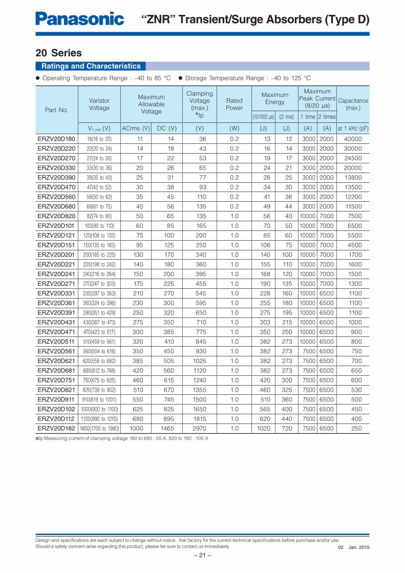
– 21 –
● Operating Temperature Range : –40 to 85 °C ● Storage Temperature Range : –40 to 125 °C
Ratings and Characteristics
20 Series
✽Ip Measuring current of clamping voltage 180 to 680 : 20 A, 820 to 182 : 100 A
Part No.
VaristorVoltage
MaximumAllowableVoltage
ClampingVoltage(max.)
✽Ip
RatedPower
MaximumEnergy
MaximumPeak Current
(8/20 μs)Capacitance
(max.)
(10/1000 μs) (2 ms) 1 time 2 times
V1 mA (V) ACrms (V) DC (V) (V) (W) (J) (J) (A) (A) at 1 kHz (pF)
ERZV20D180 18(16 to 20) 11 14 36 0.2 13 12 3000 2000 40000
ERZV20D220 22(20 to 24) 14 18 43 0.2 16 14 3000 2000 30000
ERZV20D270 27(24 to 30) 17 22 53 0.2 19 17 3000 2000 24500
ERZV20D330 33(30 to 36) 20 26 65 0.2 24 21 3000 2000 20000
ERZV20D390 39(35 to 43) 25 31 77 0.2 28 25 3000 2000 13800
ERZV20D470 47(42 to 52) 30 38 93 0.2 34 30 3000 2000 13500
ERZV20D560 56(50 to 62) 35 45 110 0.2 41 36 3000 2000 12200
ERZV20D680 68(61 to 75) 40 56 135 0.2 49 44 3000 2000 11500
ERZV20D820 82(74 to 90) 50 65 135 1.0 56 40 10000 7000 7500
ERZV20D101 100(90 to 110) 60 85 165 1.0 70 50 10000 7000 6500
ERZV20D121 120(108 to 132) 75 100 200 1.0 85 60 10000 7000 5500
ERZV20D151 150(135 to 165) 95 125 250 1.0 106 75 10000 7000 4500
ERZV20D201 200(185 to 225) 130 170 340 1.0 140 100 10000 7000 1700
ERZV20D221 220(198 to 242) 140 180 360 1.0 155 110 10000 7000 1600
ERZV20D241 240(216 to 264) 150 200 395 1.0 168 120 10000 7000 1500
ERZV20D271 270(247 to 303) 175 225 455 1.0 190 135 10000 7000 1300
ERZV20D331 330(297 to 363) 210 270 545 1.0 228 160 10000 6500 1100
ERZV20D361 360(324 to 396) 230 300 595 1.0 255 180 10000 6500 1100
ERZV20D391 390(351 to 429) 250 320 650 1.0 275 195 10000 6500 1100
ERZV20D431 430(387 to 473) 275 350 710 1.0 303 215 10000 6500 1000
ERZV20D471 470(423 to 517) 300 385 775 1.0 350 250 10000 6500 900
ERZV20D511 510(459 to 561) 320 410 845 1.0 382 273 10000 6500 800
ERZV20D561 560(504 to 616) 350 450 930 1.0 382 273 7500 6500 750
ERZV20D621 620(558 to 682) 385 505 1025 1.0 382 273 7500 6500 700
ERZV20D681 680(612 to 748) 420 560 1120 1.0 382 273 7500 6500 650
ERZV20D751 750(675 to 825) 460 615 1240 1.0 420 300 7500 6500 600
ERZV20D821 820(738 to 902) 510 670 1355 1.0 460 325 7500 6500 530
ERZV20D911 910(819 to 1001) 550 745 1500 1.0 510 360 7500 6500 500
ERZV20D102 1000(900 to 1100) 625 825 1650 1.0 565 400 7500 6500 450
ERZV20D112 1100(990 to 1210) 680 895 1815 1.0 620 440 7500 6500 400
ERZV20D182 1800(1700 to 1980) 1000 1465 2970 1.0 1020 720 7500 6500 250
Jan. 201502

Design and specifications are each subject to change without notice. Ask factory for the current technical specifications before purchase and/or use.
Should a safety concern arise regarding this product, please be sure to contact us immediately.
“ZNR” Transient/Surge Absorbers (Type D)
– 22 –
W
L
DT
W
H20.0
min
.
f 1.0
L
L
DT
W2H20.0
min
.
f 1.0
L
10000
1000
100
10
120 100 1000 10000
106 Times
105 Times
104 Times
10 3 Times
10 2 Times
10 Times
2 Times
1 Time
Impulse Width (μs)
Imp
uls
e C
urr
en
t (A
)
5 min. interval
2 min. interval
10 sec. interval
2 times :
up to 10 times :
up to 106 times :
400
300
200
1009080706050
40
30
76
5
20
1098
10–6 10–5 10–4 10–3 10–2 10–1 100 101 102 103 104 105
180
220
270330390
470560680
560
470
390330
270
220
180
680
3
4
Vo
lta
ge
(V
)
Current (A)
Test current waveform
10–6 to 10–3 A: Direct current
10–1 to 104 A: 8/20 μs
Max. Clamping VoltageMax.
Leakage Current
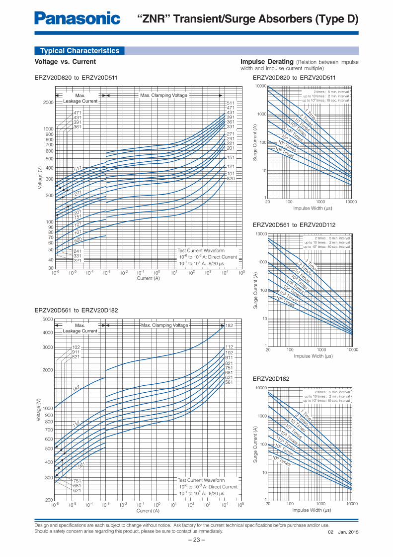
Typical CharacteristicsVoltage vs. Current Impulse Derating (Relation between impulse
width and impulse current multiple)
Dimensions in mm (not to scale) ✽ Refer to page 24 to 26 about leads cut type and taping.
✽: W2
(ERZV20D182)
ERZV20D180 to ERZV20D680 ERZV20D180 to ERZV20D680
Part No. D max. T max. W±1.0 H max. L±1.0
ERZV20D180 21.5 5.1 10.0 24.5 1.5ERZV20D220 21.5 5.2 10.0 24.5 1.6ERZV20D270 21.5 5.3 10.0 24.5 1.7ERZV20D330 21.5 5.5 10.0 24.5 1.9ERZV20D390 21.5 5.5 10.0 24.5 1.9ERZV20D470 21.5 5.6 10.0 24.5 2.0ERZV20D560 21.5 5.7 10.0 24.5 2.1ERZV20D680 21.5 5.8 10.0 24.5 2.2ERZV20D820 21.5 4.9 10.0 24.5 1.8ERZV20D101 21.5 5.1 10.0 24.5 2.0ERZV20D121 21.5 5.3 10.0 24.5 2.2ERZV20D151 21.5 5.6 10.0 24.5 2.5ERZV20D201 21.5 5.2 10.0 24.5 2.1ERZV20D221 21.5 5.3 10.0 24.5 2.2ERZV20D241 21.5 5.4 10.0 24.5 2.3ERZV20D271 21.5 5.6 10.0 24.5 2.5ERZV20D331 21.5 5.9 10.0 24.5 2.8ERZV20D361 21.5 6.1 10.0 24.5 3.0ERZV20D391 21.5 6.2 10.0 24.5 3.1ERZV20D431 21.5 6.4 10.0 24.5 3.3ERZV20D471 21.5 6.6 10.0 24.5 3.5ERZV20D511 21.5 6.8 10.0 24.5 3.7ERZV20D561 22.5 7.1 10.0 25.5 4.2ERZV20D621 22.5 7.5 10.0 25.5 4.4ERZV20D681 22.5 7.8 10.0 25.5 4.7ERZV20D751 22.5 8.2 10.0 25.5 5.1ERZV20D821 22.5 8.5 10.0 25.5 5.4ERZV20D911 22.5 9.0 10.0 25.5 5.9ERZV20D102 22.5 9.5 10.0 25.5 6.4ERZV20D112 22.5 10.1 10.0 25.5 7.0ERZV20D182 23.5 14.8 15.0✽ 28.0 10.7(±2.0)
Jan. 201502
Design and specifications are each subject to change without notice. Ask factory for the current technical specifications before purchase and/or use.
Should a safety concern arise regarding this product, please be sure to contact us immediately.
“ZNR” Transient/Surge Absorbers (Type D)
– 23 –
30
40
50
60708090
100
200
300
400
500
600
700800900
1000
2000
121511
271
201
151
121
101
820
10-6 10-5 10-4 10-3 10-2 10-1 100 101 102 103 104 105
101820
151
511471431391361331
271241221201
Vo
lta
ge
(V
)
Test Current Waveform
10-6 to 10-3 A: Direct Current
10-1 to 104 A: 8/20 μs
Current (A)
Max. Clamping VoltageMax.
Leakage Current
241331221
471431391361
5000
4000
3000
2000
1000
900
800
700
600
500
400
300
200
112
10-6 10-5 10-4 10-3 10-2 10-1 100 101 102 103 104 105
112
102911
821
182
182
Voltag
e (
V)
Current (A)
Test Current Waveform
10-6 to 10-3 A: Direct Current
10-1 to 10
4 A: 8/20 μs
561
751681621561
Max.
Leakage Current
Max. Clamping Voltage
751681621
102911821
Impulse Width (μs)
Su
rge
Cu
rre
nt (A
)
10000
1000
100
10
20 100 1000
1 Time
2 Times
10 Times
10 2 Times
10 3 Times
10 4 Times10 5 Times106 Times
110000
5 min. interval
2 min. interval
10 sec. interval
2 times :
up to 10 times :
up to 106 times :
Impulse Width (μs)
Surg
e C
urr
ent
(A)
10000
1000
100
10
20 100 1000
1 Time
2 Times
10 Times
10 2 Times
10 5 Times106 Times
10 4 Times
10 3 Times
110000
5 min. interval
2 min. interval
10 sec. interval
2 times :
up to 10 times :
up to 106 times :
Impulse Width (μs)
Surg
e C
urr
ent (A
)
10000
1000
100
10
20 100 1000
10 Times
2 Times
1 Time
10 2 Times
10 3 Times
10 4 Times10 5 Times
106 Times
110000
5 min. interval
2 min. interval
10 sec. interval
2 times :
up to 10 times :
up to 106 times :
Typical CharacteristicsVoltage vs. Current Impulse Derating (Relation between impulse
width and impulse current multiple)
ERZV20D820 to ERZV20D511
ERZV20D561 to ERZV20D182
ERZV20D820 to ERZV20D511
ERZV20D561 to ERZV20D112
ERZV20D182
Jan. 201502

Design and specifications are each subject to change without notice. Ask factory for the current technical specifications before purchase and/or use.
Should a safety concern arise regarding this product, please be sure to contact us immediately.
“ZNR” Transient/Surge Absorbers (Type D)
– 24 –
D
H
W
fd
B
5
180 to 471
7.0 max.
10.0 max.
5.0±1.0
0.60 –0.05
4.0±1.0
+0.06
7
180 to 511
8.5 max.
11.5 max.
5.0±1.0
0.60 –0.05
4.0±1.0
9
180 to 511
11.5 max.
14.0 max.
5.0±1.0
0.60 –0.05
4.0±1.0
+0.06 +0.06
180 to 511
11.5 max.
14.5 max.
7.5±1.0
0.80 –0.05
4.0±1.0
10
561 to 751
12.5 max.
15.5 max.
7.5±1.0
0.80 –0.05
4.0±1.0
821 to 112
12.5 max.
15.5 max.
7.5±1.0
0.80 –0.05
4.0±1.5
180 to 511
15.5 max.
18.5 max.
7.5±1.0
0.80 –0.05
4.0±1.0
14
561 to 751
16.0 max.
19.0 max.
7.5±1.0
0.80 –0.05
4.0±1.0
821 to 112
16.0 max.
19.0 max.
7.5±1.0
0.80 –0.05
4.0±1.5
+0.08 +0.08 +0.08 +0.08 +0.08 +0.08
ERZV05D□□□CS ERZV07D□□□CS ERZV09D□□□CS ERZV10D□□□CS ERZV10D□□□CS ERZV10D□□□C1 ERZV14D□□□CS ERZV14D□□□CS ERZV14D□□□C1
Series
Varistor VoltageSymbol
StandardProductsPart No.
A
D
C
W
fd
B
5
180 to 471
13.0 max.
7.0 max.
1.2±0.4
5.0±1.0
0.60 –0.05
4.0±1.0
+0.06
7
180 to 511
14.5 max.
8.5 max.
1.2±0.4
5.0±1.0
0.60 –0.05
4.0±1.0
9
180 to 511
17.5 max.
11.5 max.
1.2±0.4
5.0±1.0
0.60 –0.05
4.0±1.0
+0.06 +0.06
180 to 511
17.5 max.
11.5 max.
1.4±0.4
7.5±1.0
0.80 –0.05
4.0±1.0
10
561 to 751
19.0 max.
12.5 max.
1.4±0.4
7.5±1.0
0.80 –0.05
4.0±1.0
821 to 112
20.0 max.
12.5 max.
1.4±0.4
7.5±1.0
0.80 –0.05
4.0±1.5
180 to 511
21.0 max.
15.5 max.
1.4±0.4
7.5±1.0
0.80 –0.05
4.0±1.0
14
561 to 751
22.0 max.
16.0 max.
1.4±0.4
7.5±1.0
0.80 –0.05
4.0±1.0
821 to 112
23.5 max.
16.0 max.
1.4±0.4
7.5±1.0
0.80 –0.05
4.0±1.5
+0.08 +0.08 +0.08 +0.08 +0.08 +0.08
ERZV05V□□□CS ERZV07V□□□CS ERZV09V□□□CS ERZV10V□□□CS ERZV10V□□□CS ERZV10V□□□C1 ERZV14V□□□CS ERZV14V□□□CS ERZV14V□□□C1
Series
Varistor VoltageSymbol
StandardProductsPart No.
D T✽✽
L✽W
fd
HB
D T✽✽
L✽W
fd
C
A
B
✽✽✽
C
Ratings and Characteristics
Ratings and Characteristics
Dimensions in mm (not to scale)
Dimensions in mm (not to scale)
Straight Leads Cut Type (Bulk Type)
✽ Refer to bulk standard type part no. (P9 to P23).
✽ Refer to bulk standard type part no. (P9 to P23).
notes ✽ Dimension “L”: Conforms to each individtual specification. ✽✽ Dimension “T”: Conforms to each individual specification.
Crimped Leads Cut Type (Bulk Type)
notes ✽ Dimension “L”: Conforms to each individual specification. ✽✽ Dimension “T”: Conforms to each individual specification. ✽✽✽ Resin extenyions : No resin below the center of the hook.
Unit : mm
Unit : mm
Jan. 201503
Design and specifications are each subject to change without notice. Ask factory for the current technical specifications before purchase and/or use.
Should a safety concern arise regarding this product, please be sure to contact us immediately.
“ZNR” Transient/Surge Absorbers (Type D)
– 25 –
P0
P2 P
P1
f D0
f D
f d
F
L
A
W
t
W0
W2
W1
HH0
T✽
△h
F1
Position of H0 dimension
Position of F1 dimension
P0
P2
P
P1
f D0
f D
F
L
A
W
t
W0
W2
W1
HH0
T✻
△h
F1
f d Position of H0 dimension
Position of F1 dimension
P
P0
P1
P2
f dF
Δh
W
W0
W1
W2
H
H0
F1
f D0
t
L
f DA
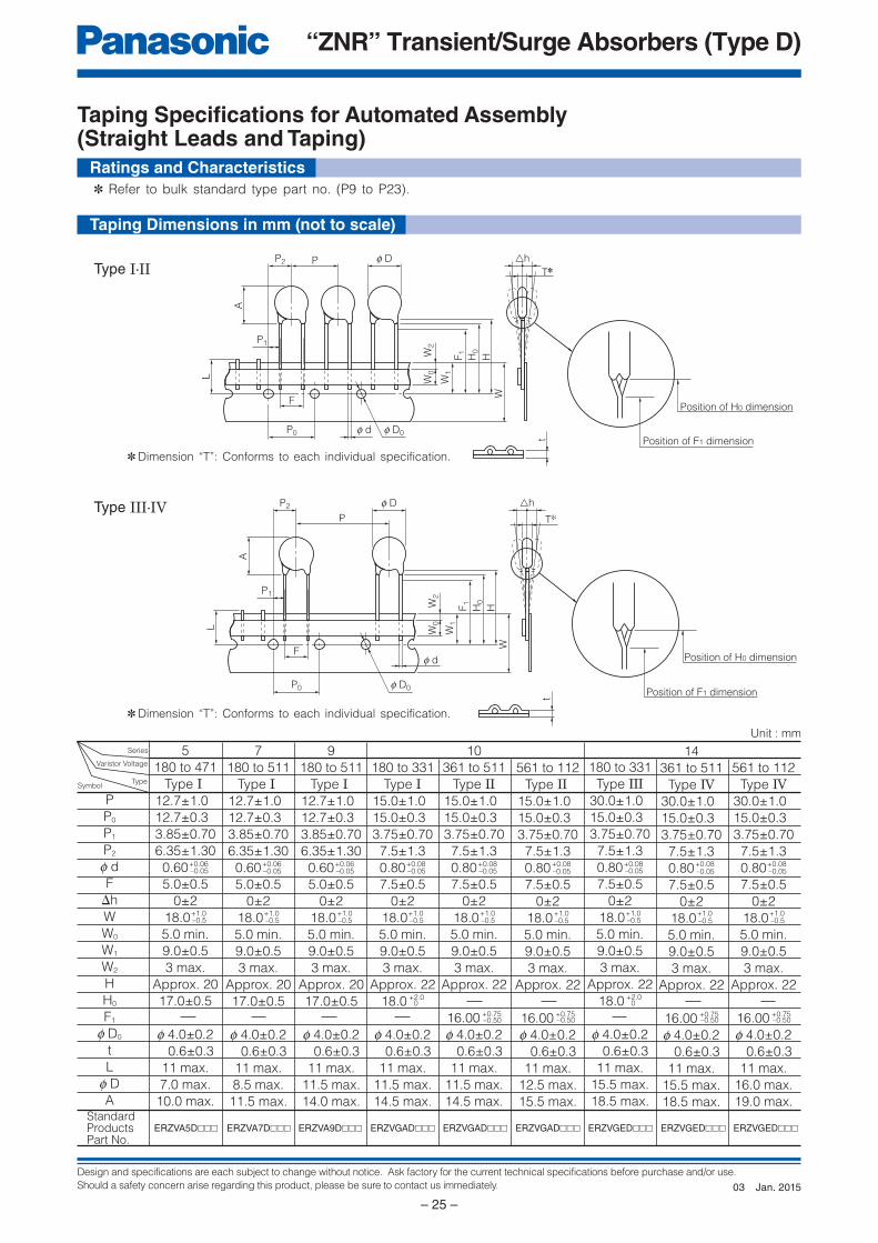
5
180 to 471
Type I 12.7±1.0
12.7±0.3
3.85±0.70
6.35±1.30
0.60 –0.05
5.0±0.5
0±2
18.0 –0.5
5.0 min.
9.0±0.5
3 max.
Approx. 20
17.0±0.5
f 4.0±0.2
0.6±0.3
11 max.
7.0 max.
10.0 max.
+0.06 +0.06 +0.06 +0.08 +0.08 +0.08 +0.08 +0.08 +0.08
ERZVA5D□□□ ERZVA7D□□□ ERZVA9D□□□ ERZVGAD□□□ ERZVGAD□□□ ERZVGAD□□□ ERZVGED□□□ ERZVGED□□□ ERZVGED□□□
7
180 to 511
Type I 12.7±1.0
12.7±0.3
3.85±0.70
6.35±1.30
0.60 –0.05
5.0±0.5
0±2
18.0 –0.5
5.0 min.
9.0±0.5
3 max.
Approx. 20
17.0±0.5
f 4.0±0.2
0.6±0.3
11 max.
8.5 max.
11.5 max.
9
180 to 511
Type I 12.7±1.0
12.7±0.3
3.85±0.70
6.35±1.30
0.60 –0.05
5.0±0.5
0±2
18.0 –0.5
5.0 min.
9.0±0.5
3 max.
Approx. 20
17.0±0.5
f 4.0±0.2
0.6±0.3
11 max.
11.5 max.
14.0 max.
180 to 331
Type I15.0±1.0
15.0±0.3
3.75±0.70
7.5±1.3
0.80 –0.05
7.5±0.5
0±2
18.0 –0.5
5.0 min.
9.0±0.5
3 max.
Approx. 22
18.0 +2.0
f 4.0±0.2
0.6±0.3
11 max.
11.5 max.
14.5 max.
10
361 to 511
Type II15.0±1.0
15.0±0.3
3.75±0.70
7.5±1.3
0.80 –0.05
7.5±0.5
0±2
18.0 –0.5
5.0 min.
9.0±0.5
3 max.
Approx. 22
16.00 +0.75
f 4.0±0.2
0.6±0.3
11 max.
11.5 max.
14.5 max.
561 to 112
Type II 15.0±1.0
15.0±0.3
3.75±0.70
7.5±1.3
0.80 –0.05
7.5±0.5
0±2
18.0 –0.5
5.0 min.
9.0±0.5
3 max.
Approx. 22
16.00 +0.75
f 4.0±0.2
0.6±0.3
11 max.
12.5 max.
15.5 max.
180 to 331
Type III30.0±1.0
15.0±0.3
3.75±0.70
7.5±1.3
0.80 –0.05
7.5±0.5
0±2
18.0 –0.5
5.0 min.
9.0±0.5
3 max.
Approx. 22
18.0 +2.0
f 4.0±0.2
0.6±0.3
11 max.
15.5 max.
18.5 max.
14
361 to 511
Type IV30.0±1.0
15.0±0.3
3.75±0.70
7.5±1.3
0.80 –0.05
7.5±0.5
0±2
18.0 –0.5
5.0 min.
9.0±0.5
3 max.
Approx. 22
16.00 +0.75
f 4.0±0.2
0.6±0.3
11 max.
15.5 max.
18.5 max.
561 to 112
Type IV30.0±1.0
15.0±0.3
3.75±0.70
7.5±1.3
0.80 –0.05
7.5±0.5
0±2
18.0 –0.5
5.0 min.
9.0±0.5
3 max.
Approx. 22
16.00 +0.75
f 4.0±0.2
0.6±0.3
11 max.
16.0 max.
19.0 max.
0 0
–0.50–0.50 –0.50 –0.50
+1.0 +1.0 +1.0 +1.0 +1.0 +1.0 +1.0 +1.0 +1.0
Type
Varistor Voltage
Symbol
StandardProductsPart No.
Series
Ratings and Characteristics
Taping Dimensions in mm (not to scale)
✽ Refer to bulk standard type part no. (P9 to P23).
✽ Dimension “T”: Conforms to each individual specification.
Taping Specifi cations for Automated Assembly(Straight Leads and Taping)
Type I·II
✽ Dimension “T”: Conforms to each individual specification.
Type III·IV
Unit : mm
Jan. 201503

Design and specifications are each subject to change without notice. Ask factory for the current technical specifications before purchase and/or use.
Should a safety concern arise regarding this product, please be sure to contact us immediately.
“ZNR” Transient/Surge Absorbers (Type D)
– 26 –
P
P0
P1
P2
f dF
Δh
W
W0
W1
W2
H
H0
f D0
t
L
f DA
5
180 to 471
Type I12.7±1.0
12.7±0.3
3.85±0.70
6.35±1.30
0.60 –0.05
5.0±0.5
0±2
18.0 –0.5
5.0 min.
9.0±0.5
3 max.
Approx. 22
17.0±0.5
f4.0±0.2
0.6±0.3
11 max.
7.0 max.
13.0 max.
+0.06 +0.06 +0.06 +0.08 +0.08 +0.08 +0.08 +0.08 +0.08
ERZVA5V□□□ ERZVA7V□□□ ERZVA9V□□□ ERZVEAV□□□ ERZVEAV□□□ ERZVEAV□□□ ERZVEEV□□□ ERZVEEV□□□ ERZVEEV□□□
7
180 to 511
Type I12.7±1.0
12.7±0.3
3.85±0.70
6.35±1.30
0.60 –0.05
5.0±0.5
0±2
18.0 –0.5
5.0 min.
9.0±0.5
3 max.
Approx. 22
17.0±0.5
f4.0±0.2
0.6±0.3
11 max.
8.5 max.
14.5 max.
9
180 to 511
Type I12.7±1.0
12.7±0.3
3.85±0.70
6.35±1.30
0.60 –0.05
5.0±0.5
0±2
18.0 –0.5
5.0 min.
9.0±0.5
3 max.
Approx. 22
17.0±0.5
f4.0±0.2
0.6±0.3
11 max.
11.5 max.
17.5 max.
180 to 331
Type I15.0±1.0
15.0±0.3
3.75±0.70
7.5±1.3
0.80 –0.05
7.5±0.5
0±2
18.0 –0.5
5.0 min.
9.0±0.5
3 max.
Approx. 22
16.0±0.5
f4.0±0.2
0.6±0.3
11 max.
11.5 max.
17.5 max.
10
361 to 511
Type I15.0±1.0
15.0±0.3
3.75±0.70
7.5±1.3
0.80 –0.05
7.5±0.5
0±2
18.0 –0.5
5.0 min.
9.0±0.5
3 max.
Approx. 22
16.0±0.5
f4.0±0.2
0.6±0.3
11 max.
11.5 max.
17.5 max.
561 to 112
Type I15.0±1.0
15.0±0.3
3.75±0.70
7.5±1.3
0.80 –0.05
7.5±0.5
0±2
18.0 –0.5
5.0 min.
9.0±0.5
3 max.
Approx. 22
16.0±0.5
f4.0±0.2
0.6±0.3
11 max.
12.5 max.
✽ (refer)
180 to 331
Type II30.0±1.0
15.0±0.3
3.75±0.70
7.5±1.3
0.80 –0.05
7.5±0.5
0±2
18.0 –0.5
5.0 min.
9.0±0.5
3 max.
Approx. 22
16.0±0.5
f4.0±0.2
0.6±0.3
11 max.
15.5 max.
21.0 max.
14
361 to 511
Type II30.0±1.0
15.0±0.3
3.75±0.70
7.5±1.3
0.80 –0.05
7.5±0.5
0±2
18.0 –0.5
5.0 min.
9.0±0.5
3 max.
Approx. 22
16.0±0.5
f4.0±0.2
0.6±0.3
11 max.
15.5 max.
21.0 max.
561 to 112
Type II30.0±1.0
15.0±0.3
3.75±0.70
7.5±1.3
0.80 –0.05
7.5±0.5
0±2
18.0 –0.5
5.0 min.
9.0±0.5
3 max.
Approx. 22
16.0±0.5
f4.0±0.2
0.6±0.3
11 max.
16.0 max.
✽ (refer)
+1.0 +1.0 +1.0 +1.0 +1.0 +1.0 +1.0 +1.0 +1.0
StandardProductsPart No.
Type
Varistor Voltage
Symbol
Series
P0
P2 P
P1
f D0
f D
f d
F
L
A
W
t
W0
W2
W1
HH0
T✽
△h
P0
P2
P
P1
f D0
f D
f dF
L
A
W
t
W0
W2
W1
HH0
T✽
△h
✽ Dimension “T”: Conforms to each individual specifi cation.
Type I
Type II
✽ Dimension “T”: Conforms to each individual specifi cation.
✽ Dimension “A”
10 Series 14 SeriesERZV□□V561 19.0 max. 22.0 max.ERZV□□V621 19.0 max. 22.0 max.ERZV□□V681 19.0 max. 22.0 max.ERZV□□V751 19.0 max. 22.0 max.
10 Series 14 SeriesERZV□□V821 20.0 max. 23.5 max.ERZV□□V911 20.0 max. 23.5 max.ERZV□□V102 20.0 max. 23.5 max.ERZV□□V112 20.0 max. 23.5 max.
Ratings and Characteristics
Taping Dimensions in mm (not to scale)
✽ Refer to bulk standard type part no. (P9 to P23).
Taping Specifi cations for Automated Assembly(Crimped Leads and Taping)
Unit : mm
Jan. 201503

Design and specifications are each subject to change without notice. Ask factory for the current technical specifications before purchase and/or use.
Should a safety concern arise regarding this product, please be sure to contact us immediately.
“ZNR” Transient/Surge Absorbers (Type D)
– 27 –
Application Note for Safety Standards
● Approvals products lists in "Reference Guide to Standard Products."● UL, VDE and CSA : Registered in "Type name", it isn’t registered in "Panasonic Part No."● CQC : Registered in "Panasonic Part No."● "Rated Voltages" are specifi ed for UL recognized components in list shown below.
■ The AC Rated Voltage and Maximum Allowable Voltage
✽:5 Series is blank, 7 series is 7, 9 series is 9, 10 series is 10, 14 series is 14, 20 series is 20
Type Name
Maximum AllowableVoltage
Rated Voltage (Vrms)
ACrms (V) DC (V) UL1449 CSA C22.2 No.1
V✽820U 50 65 45 N/A
V✽101U 60 85 55 N/A
V✽121U 75 100 68 N/A
V✽151U 95 125 86 N/A
V✽201U 130 170 118 118
V✽221U 140 180 127 127
V✽241U 150 200 136 136
V✽271U 175 225 159 159
V✽331U 210 270 189 189
V✽361U 230 300 209 209
V✽391U 250 320 227 227
V✽431U 275 350 250 250
V✽471U 300 385 272 272
V✽511U 320 410 291 291
V✽561U 350 450 320 320
V✽621U 385 505 350 350
V✽681U 420 560 381 381
V✽751U 460 615 418 418
V✽821U 510 670 463 463
V✽911U 550 745 500 500
V✽102U 625 825 568 568
V✽112U 680 895 600 618
V✽182U 1000 1465 600 909
Jan. 201503

Design and specifications are each subject to change without notice. Ask factory for the current technical specifications before purchase and/or use.
Should a safety concern arise regarding this product, please be sure to contact us immediately.
“ZNR” Transient/Surge Absorbers (Type D)
– 28 –
5(ERZV05D□□□)
180 to 680
820 to 151
201 or more
7(ERZV07D□□□)
9(ERZV09D□□□)
10(ERZV10D□□□)
14(ERZV14D□□□)
20(ERZV20D□□□)
V□□□ V7□□□ V9□□□ ZNR
V10□□□ ZNR
V14□□□ ZNR
V20□□□
VaristerVoltage
Series(Example)
V□□□U V7□□□U V9□□□U
ZNRV10□□□U
ZNRV14□□□U
ZNRV20□□□U
V□□□U V7□□□U V9□□□U
ZNRV10□□□U
ZNRV14□□□U
ZNRV20□□□U
Marking
Marking ContentsExplanation of the contents
Marking Contents
✽ : 5 series is blank, 7 series is 7, 9 series is 9, 10 series is 10, 14 series is 14,20 series is 20
1) : If the 10's digit of a Christian year is an even year, as an end abbreviation, an alphabetic character is used.1:A, 2:B, 3:C, 4:D, 5:E, 6:F, 7:G, 8:H, 9:J, 0:KIf the 10's digit of a Christian year is an odd year, as an end abbreviation, a number is used.
Mark Explanation of the content
ZNR Product Name
V✽□□□V✽□□□U
Abbreviation of Part No.(Type Name)
[□□□]
Nominal VaristorVolage
◯ Factory Identication MarkNone:Japan
Q:Indonesia
1) ◆ Year Code2013:3, 2014:4, 2015:5
2016:6, 2017:7, 2018:8
◇ Monthly CodeJan:1 to Sep:9,
Oct:O, Nov:N, Dec:D
UL Recognized Components Mark
CSA Monogram
Jan. 201503

Design and specifications are each subject to change without notice. Ask factory for the current technical specifications before purchase and/or use.
Should a safety concern arise regarding this product, please be sure to contact us immediately.
“ZNR” Transient/Surge Absorbers (Type D)
– 29 –
Characteristics Test Methods/Description Specifi cations
Standard Test ConditionElectrical measurements (initial/after tests) shall be conducted at tem per a ture of 5 to 35 °C, relative humidity of maximum 85 %
———
Ele
ctric
al
Varistor VoltageThe voltage between two terminals with the specifi ed measuring cur rent CmA DC applied is called VC or VCmA. The mea sure ment shall be made as fast as pos si ble to avoid heat affection.
To meet thespecifi ed value.
MaximumAllowable Volt age
The maximum sinusoidal RMS voltage or maximum DC voltage that can be applied continuously.
Clamping Voltage
The maximum voltage between two terminals with the specifi ed stan dard impulse current (8/20 μs) illustrated below applied.
Time
100 90
50
10 0
Curr
ent(
%)
8 μs20 μs
Rated PowerThe power that can be applied in the specifi ed ambienttemperature.
Maximum EnergyThe maximum energy within the varistor voltage change of ±10 % when a single impulse current of 2 ms or 10/1000 μs is ap plied.
MaximumPeak
Current(Withstanding
SurgeCurrent)
2 timesThe maximum current within the varistor voltage change of ±10 % when a standard im pulse current of 8/20 μs is applied two times with an interval of 5 minutes.
1 timeThe maximum current within the varistor voltage change of ±10 % with a single standard im pulse current of 8/20 μs is ap plied.
Temperature Co ef fi cient of Varistor Voltage
VCmA at 85 °C – VCmA at 25 °C×
1× 100 (%/°C)
VCmA at 25 °C 600 to -0.05 %/°C max.
CapacitanceCapacitance shall be measured at 1 kHz ±10 %, 1 Vrms max. (1 MHz ±10 % below 100 pF), 0 V bias and 20±2 °C.
To meet thespecifi ed value
Withstanding Voltage(Body Insulation)
The specifi ed voltage shall be applied between both terminals of the spec i men connected together and met al foil closely wrapped round its body for 1 minute.
Classifi cation (Nom i nal varistor voltage) Test Voltage (AC)
V0.1 mA, V1 mA < 330 V 1000 Vrms
V0.1 mA, V1 mA > 330 V 1500 Vrms
No breakdown
Impulse Life
The change of VC shall be measured after the impulse current list ed be low is applied 10000 or 100000 times con tin u ous ly with the interval of 10 seconds at room temperature.
Item Impulse Life (I) Impulse Life (II)
Times ×104 Times ×105 Times
Part No. Current Impulse Current
ERZV05D180 to ERZV05D680 8 A (8/20 μs) 5 A (8/20 μs)
ERZV07D180 to ERZV07D680 25 A (8/20 μs) 15 A (8/20 μs)
ERZV09D180 to ERZV09D680 50 A (8/20 μs) 35 A (8/20 μs)
ERZV10D180 to ERZV10D680 50 A (8/20 μs) 35 A (8/20 μs)
ERZV14D180 to ERZV14D680 90 A (8/20 μs) 50 A (8/20 μs)
ERZV20D180 to ERZV20D680 130 A (8/20 μs) 65 A (8/20 μs)
ERZV05D820 to ERZV05D471 40 A (8/20 μs) 25 A (8/20 μs)
ERZV07D820 to ERZV07D511 100 A (8/20 μs) 60 A (8/20 μs)
ERZV09D820 to ERZV09D511 150 A (8/20 μs) 85 A (8/20 μs)
ERZV10D820 to ERZV10D112 150 A (8/20 μs) 85 A (8/20 μs)
ERZV10D182CS 120 A (8/20 μs) 75 A (8/20 μs)
ERZV14D820 to ERZV14D112 200 A (8/20 μs) 110 A (8/20 μs)
ERZV14D182CS 150 A (8/20 μs) 90 A (8/20 μs)
ERZV20D820 to ERZV20D112 250 A (8/20 μs) 120 A (8/20 μs)
ERZV20D182 200 A (8/20 μs) 100 A (8/20 μs)
ΔVCmA/VCmA < ±10 %
Performance Characteristics
Jan. 201503

Design and specifications are each subject to change without notice. Ask factory for the current technical specifications before purchase and/or use.
Should a safety concern arise regarding this product, please be sure to contact us immediately.
“ZNR” Transient/Surge Absorbers (Type D)
– 30 –
Performance Characteristics
Characteristics Test Methods Specifi cations
Mec
hani
cal
Robustness ofTerminations(Tensile)
After gradually applying the force specifi ed below and keeping the unit fi xed for 10 seconds, the terminal shall be visually examined for any damage.
Terminal diameter Force
00.6 mm, 00.8 mm01.0 mm
9.8 N19.6 N
No remarkablemechanical damageRobustness of
Terminations(Bending)
The unit shall be secured with its terminal kept vertical and the force specifi ed below shall be applied in the axial direction.The terminal shall gradually be bent by 90 ° in one direction, then 90 ° in the opposite direction, and again back to the original po si tion.The damage of the terminal shall be visually examined.
Terminal diameter Force
00.6 mm, 00.8 mm01.0 mm
4.9 N9.8 N
Vibration
After repeadly applying a single harmonic vibration (amplitude: 0.75 mm, double amplitude: 1.5 mm) with 1 minute vibration frequency cycles (10 Hz to 55 Hz to 10 Hz) to each of three perpendicular directions for 2 hours. Thereafter, the unit shall be visually ex amined.
SolderabilityAfter dipping the terminals to a depth of approximately 3 mm from the body in a soldering bath of 235±5°C for 2±0.5 seconds, the terminal shall be visually examined.
Approximately 95 % of the termainals shall be covered with new solder uni form ly.
Resistance toSoldering Heat
After each lead shall be dipped into a solder bath having a temperature of 260±5 °C to a point 2.0 to 2.5 mm from the body of the unit, using shielding board (t=1.5 mm), be held there for 10±1 s and then be stored at room temperature and normal humidity for 1 to 2 hours. The change of VCmA and mechanical damages shall be examined.
ΔVCmA/VCmA < ±5 %No remarkablemechanical damage
Env
ironm
enta
l
High TemperatureStorage/Dry Heat
The specimen shall be subjected to 125±2 °C for 1000 hours in a ther mo stat ic bath without load and then stored at room temperature and normal humidity for 1 to 2 hours. Thereafter, the change of VCmA shall be mea sured.
ΔVCmA/VCmA < ±5 %
Humidity
The specimen shall be subjected to 40±2 °C, 90 to 95 % RH for 1000 hours without load and then stored at room temperature and normal humidity for 1 to 2 hours. Thereafter, the change of VCmA shall be measured.
ΔVCmA/VCmA < ±5 %
TemperatureCycle
The temperature cycle shown below shall be repeated fi ve cycles and then stored at room temperature and normal humidity for 1 to 2 hours. The change of VCmA and mechanical damage shall beexamined.
Step Temperature (°C) Period (minutes)
1 –40±3 30±3
2 Room temperature 15±3
3 125±2 30±3
4 Room temperature 15±3
ΔVCmA/VCmA < ±5 %No remarkablemechanical damage
High Temperature Load/Dry Heat Load
After being continuously applied the Maximum Allowable Voltage at 85±2 °C for 1000 hours, the specimen shall be stored at room temperature and normal humidity for 1 to 2 hours. Thereafter, the change of VCmA shall be measured.
ΔVCmA/VCmA < ±10 %
Damp Heat Load/Humidity Load
The specimen shall be subjected to 40±2 °C, 90 to 95 % RH and the Maximum Allowable Voltage for 1000 hours and then stored at room temperature and normal humidity for 1 to 2 hours. Thereafter, the change of VCmA shall be measured.
Low TemperatureStorage/Cold
The specimen shall be subjected to –40±2 °C without load for 1000 hours and then stored at room temperature and normal humidity for 1 to 2 hours. Thereafter, the change of VCmA shall be measured.
ΔVCmA/VCmA < ±5 %
Jan. 201503

Design and specifications are each subject to change without notice. Ask factory for the current technical specifications before purchase and/or use.
Should a safety concern arise regarding this product, please be sure to contact us immediately.
“ZNR” Transient/Surge Absorbers (Type D)
– 31 –
E
1
R
2
Z
3
E
4 5 6 7 8 9 10
Product Code
11 12
Design No.
Series
Series E8E08
E11 Series E11
Series E14
Lead Configuration
E14
The first two digits are significant
figures and the third one denotes
the number of zeros following.
Nominal Varistor Voltage
Packaging
Bulk
Bulk
Taped
Taped
Lead Configuration
Straight Lead
Crimped Lead
Straight Lead
Crimped Lead
Symbol
1) Excluding E14, only the lead cut2) Excluding E14
A1) B2) E2) F
Series E5E05
E07 Series E7
E10 Series E10
“ZNR” Transient/Surge Absorbers
Type: DSeries: E
Explanation of Part Numbers
Features
Recommended Applications
Applicable Standards
● Large withstanding surge current capability in compact sizes● Large “Energy Handling Capability” absorbing transient overvoltages in compact sizes● Wide range of varistor voltages● RoHS compliant
● Transistor, diode, IC, thyristor or triac semiconductor protection● Surge protection in consumer electronic equipment● Surge protection in communication, measuring or controller electronics● Surge protection in electronic home appliances, gas or petroleum appliances
● UL1449 (VZCA2/UL, VZCA8/C-UL)● VDE IEC61051-1, -2, -2-2, IEC60950-1 Annex.Q● CQC(GB/T10193, GB/T10194, GB4943.1, GB8898)
Refer to pages 32 to 33, and 49 for the details
■ As for Handling Precautions and Minimum Quantity / Packing Unit Please see Related Information
“ZNR” Transient/Surge Absorber, Series E, Type D features large surge current and energy handling capability for absorbing transient overvoltage in a compact size.
Apr. 201709

Design and specifications are each subject to change without notice. Ask factory for the current technical specifications before purchase and/or use.
Should a safety concern arise regarding this product, please be sure to contact us immediately.
“ZNR” Transient/Surge Absorbers (Type D)
– 32 –
Reference Guide to Standard Products
Part No.
ApplicableStandards
VaristorVoltageat 1 mA
MaximumAllowableVoltage
ClampingVoltage
at 8/20μs
MaximumPeak Currentat 8/20μs(A) Recommended Applications
Type Name
Approvals (V) ACrms (V) DC (V) max.(V) Ip (A) 1 time 2 times
ERZE05A201 E201 ○☆◇
200(185 to 225)
130 170
340 10 1200 600
AC 100 V Line–LineApplications
ERZE07A201 E7201 ○☆◇ 340 25 2500 1250
ERZE08A201 E8201 ○☆◇ 340 25 3500 2500
ERZE10A201 E10201 ○☆◇ 340 50 4500 3000
ERZE11A201 E11201 ○☆★◇◆ 340 50 6000 5000
ERZE14A201 E14201 ○☆★◇◆ 340 100 10000 7000
ERZE05A221 E221 ○☆◇
220(198 to 242)
140 180
360 10 1200 600
ERZE07A221 E7221 ○☆◇ 360 25 2500 1250
ERZE08A221 E8221 ○☆◇ 360 25 3500 2500
ERZE10A221 E10221 ○☆◇ 360 50 4500 3500
ERZE11A221 E11221 ○☆★◇◆ 360 50 6000 5000
ERZE14A221 E14221 ○☆★◇◆ 360 100 10000 7000
ERZE05A241 E241 ○☆◇
240(216 to 264)
150 200
395 10 1200 600
AC 100 V to 120 V, Line–LineApplications
ERZE07A241 E7241 ○☆◇ 395 25 2500 1250
ERZE08A241 E8241 ○☆◇ 395 25 3500 2500
ERZE10A241 E10241 ○☆◇ 395 50 4500 3000
ERZE11A241 E11241 ○☆★◇◆ 395 50 6000 5000
ERZE14A241 E14241 ○☆★◇◆ 395 100 10000 7000
ERZE05A271 E271 ○☆◇
270(247 to 303)
175 225
455 10 1200 600
ERZE07A271 E7271 ○☆◇ 455 25 2500 1250
ERZE08A271 E8271 ○☆◇ 455 25 3500 2500
ERZE10A271 E10271 ○☆◇ 455 50 4500 3000
ERZE11A271 E11271 ○☆★◇◆ 455 50 6000 5000
ERZE14A271 E14271 ○☆★◇◆ 455 100 10000 7000
ERZE05A331 E331 ○☆◇
330(297 to 363)
210 270
545 10 1200 600
AC 100 V to 120 V, Line–LineApplications
Telephone Line Applications,(For DC 250 V Insulation Resistance Test)
ERZE07A331 E7331 ○☆◇ 545 25 2500 1250
ERZE08A331 E8331 ○☆◇ 545 25 3500 2500
ERZE10A331 E10331 ○☆◇ 545 50 4500 3000
ERZE11A331 E11331 ○☆★◇◆ 545 50 6000 4500
ERZE14A331 E14331 ○☆★◇◆ 545 100 10000 6500
ERZE05A361 E361 ○☆◇
360(324 to 396)
230 300
595 10 1200 600
ERZE07A361 E7361 ○☆◇ 595 25 2500 1250
ERZE08A361 E8361 ○☆◇ 595 25 3500 2500
ERZE10A361 E10361 ○☆◇ 595 50 4500 3000
ERZE11A361 E11361 ○☆★◇◆ 595 50 6000 4500
ERZE14A361 E14361 ○☆★◇◆ 595 100 10000 6500
ERZE05A391 E391 ○☆◇
390(351 to 429)
250 320
650 10 1200 600
ERZE07A391 E7391 ○☆◇ 650 25 2500 1250
ERZE08A391 E8391 ○☆◇ 650 25 3500 2500
ERZE10A391 E10391 ○☆◇ 650 50 4500 3000
ERZE11A391 E11391 ○☆★◇◆ 650 50 6000 4500
ERZE14A391 E14391 ○☆★◇◆ 650 100 10000 6500
ERZE05A431 E431 ○☆◇
430(387 to 473)
275 350
710 10 1200 600
AC 100 V to 220 V, Line–LineandLine–Ground Applications
ERZE07A431 E7431 ○☆◇ 710 25 2500 1250
ERZE08A431 E8431 ○☆◇ 710 25 3500 2500
ERZE10A431 E10431 ○☆◇ 710 50 4500 3000
ERZE11A431 E11431 ○☆★◇◆ 710 50 6000 4500
ERZE14A431 E14431 ○☆★◇◆ 710 100 10000 6500
◯ : UL1449 (VZCA2/UL, VZCA8/C-UL), ☆ : VDE (IEC61051-1, -2, -2-2), ★ : VDE (IEC60950-1 Annex.Q),◇ : CQC (GB/T10193, GB/T10194), ◆ : CQC (GB4943.1, GB8898)※ Approval number (File No.) of safety regulations are subject to revision without notice. Ask factory for a copy of the latest file No.
Apr. 201709

Design and specifications are each subject to change without notice. Ask factory for the current technical specifications before purchase and/or use.
Should a safety concern arise regarding this product, please be sure to contact us immediately.
“ZNR” Transient/Surge Absorbers (Type D)
– 33 –
Reference Guide to Standard Products
Part No.
ApplicableStandards
VaristorVoltageat 1 mA
MaximumAllowableVoltage
ClampingVoltage
at 8/20μs
MaximumPeak Currentat 8/20μs(A) Recommended Applications
Type Name
Approvals (V) ACrms (V) DC (V) max.(V) Ip (A) 1 time 2 times
ERZE05A471 E471 ○☆◇
470(423 to 517)
300 385
775 10 1200 600
AC 100 V to 220 V, Line–LineandLine–Ground Applications
ERZE07A471 E7471 ○☆◇ 775 25 2500 1250
ERZE08A471 E8471 ○☆★◇◆ 775 25 3500 2500
ERZE10A471 E10471 ○☆★◇◆ 775 50 4500 3000
ERZE11A471 E11471 ○☆★◇◆ 775 50 6000 4500
ERZE14A471 E14471 ○☆★◇◆ 775 100 10000 6500
ERZE07A511 E7511 ○☆◇
510(459 to 561)
320 410
845 25 2500 1250
AC 100 V to 240 V, Line–LineandLine–Ground Applications
ERZE08A511 E8511 ○☆★◇◆ 845 25 3500 2500
ERZE10A511 E10511 ○☆★◇◆ 845 50 4500 3000
ERZE11A511 E11511 ○☆★◇◆ 845 50 6000 4500
ERZE14A511 E14511 ○☆★◇◆ 845 100 10000 6500
ERZE07A561 E7561 ○☆◇
560(504 to 616)
350 450
930 25 2500 1250
ERZE08A561 E8561 ○☆★◇◆ 930 25 3500 2500
ERZE10A561 E10561 ○☆★◇◆ 930 50 4500 3000
ERZE11A561 E11561 ○☆★◇◆ 930 50 6000 4500
ERZE14A561 E14561 ○☆★◇◆ 930 100 10000 6500
ERZE07A621 E7621 ○☆◇
620(558 to 682)
385 505
1025 25 2500 1250
ERZE08A621 E8621 ○☆★◇◆ 1025 25 3500 2500
ERZE10A621 E10621 ○☆★◇◆ 1025 50 4500 3000
ERZE11A621 E11621 ○☆★◇◆ 1025 50 5000 4500
ERZE14A621 E14621 ○☆★◇◆ 1025 100 7500 6500
ERZE08A681 E8681 ○☆★◇◆
680(612 to 748)
420 560
1120 25 3500 2500
ERZE10A681 E10681 ○☆★◇◆ 1120 50 4500 3000
ERZE11A681 E11681 ○☆★◇◆ 1120 50 5000 4500
ERZE14A681 E14681 ○☆★◇◆ 1120 100 7500 6500
ERZE08A751 E8751 ○☆★◇◆
750(675 to 825)
460 615
1240 25 3500 2500
AC 380 V, Line–Line andLine–Ground Applications(For DC 500 V Insulating Test)
ERZE10A751 E10751 ○☆★◇◆ 1240 50 4500 3000
ERZE11A751 E11751 ○☆★◇◆ 1240 50 5000 4500
ERZE14A751 E14751 ○☆★◇◆ 1240 100 7500 6500
ERZE10A821 E10821 ○☆★◇◆820
(738 to 902)510 670
1355 50 4500 3000
ERZE11A821 E11821 ○☆★◇◆ 1355 50 5000 4500
ERZE14A821 E14821 ○☆★◇◆ 1355 100 7500 6500
ERZE10A911 E10911 ○☆★◇◆910
(819 to 1001)550 745
1500 50 4500 3000 AC 415 V, Line–Line andLine–Ground Applications(For DC 500 V Insulating Test)
ERZE11A911 E11911 ○☆★◇◆ 1500 50 5000 4500
ERZE14A911 E14911 ○☆★◇◆ 1500 100 7500 6500
ERZE10A102 E10102 ○☆★◇◆1000
(900 to 1100)625 825
1650 50 4500 3000
AC 480 V, Line–Line andLine–Ground Applications(For DC 500 V Insulating Test)
ERZE11A102 E11102 ○☆★◇◆ 1650 50 5000 4500
ERZE14A102 E14102 ○☆★◇◆ 1650 100 7500 6500
ERZE10A112 E10112 ○☆★◇◆1100
(990 to 1210)680 895
1815 50 4500 3000
ERZE11A112 E11112 ○☆★◇◆ 1815 50 5000 4500
ERZE14A112 E14112 ○☆★◇◆ 1815 100 7500 6500
◯ : UL1449 (VZCA2/UL, VZCA8/C-UL), ☆ : VDE (IEC61051-1, -2, -2-2), ★ : VDE (IEC60950-1 Annex.Q),◇ : CQC (GB/T10193, GB/T10194), ◆ : CQC (GB4943.1, GB8898)※ Approval number (File No.) of safety regulations are subject to revision without notice. Ask factory for a copy of the latest file No.
Apr. 201709

Design and specifications are each subject to change without notice. Ask factory for the current technical specifications before purchase and/or use.
Should a safety concern arise regarding this product, please be sure to contact us immediately.
“ZNR” Transient/Surge Absorbers (Type D)
– 34 –
DT
F
F
A20.0
min
.
f 0.6
L
L
● Operating Temperature Range : –40 to 85 °C ● Storage Temperature Range : –40 to 125 °C
Ratings and Characteristics
Series E5
Dimensions in mm (not to scale)
✽Ip Measuring current of clamping voltage : 10 A
Part No.
VaristorVoltage
MaximumAllowableVoltage
ClampingVoltage(max.)
✽Ip
RatedPower
MaximumEnergy
MaximumPeak Current
(8/20 μs)Capacitance
(max.)
(10/1000 μs) (2 ms) 1 time 2 times
V1 mA (V) ACrms (V) DC (V) (V) (W) (J) (J) (A) (A) at 1 kHz (pF)
ERZE05A201 200(185 to 225) 130 170 340 0.25 13 9.5 1200 600 200
ERZE05A221 220(198 to 242) 140 180 360 0.25 14 10 1200 600 190
ERZE05A241 240(216 to 264) 150 200 395 0.25 15 11 1200 600 170
ERZE05A271 270(247 to 303) 175 225 455 0.25 18 13 1200 600 150
ERZE05A331 330(297 to 363) 210 270 545 0.25 21 15 1200 600 130
ERZE05A361 360(324 to 396) 230 300 595 0.25 23 17 1200 600 130
ERZE05A391 390(351 to 429) 250 320 650 0.25 26 19 1200 600 130
ERZE05A431 430(387 to 473) 275 350 710 0.25 29 21 1200 600 120
ERZE05A471 470(423 to 517) 300 385 775 0.25 32 23 1200 600 100
Part No. D max. T max. F±1.0 A max. L±1.0
ERZE05A201 7.0 4.8 5.0 10.0 2.1
ERZE05A221 7.0 4.9 5.0 10.0 2.3
ERZE05A241 7.0 5.0 5.0 10.0 2.4
ERZE05A271 7.0 5.2 5.0 10.0 2.5
ERZE05A331 7.0 5.5 5.0 10.0 2.9
ERZE05A361 7.0 5.8 5.0 10.0 3.1
ERZE05A391 7.0 5.9 5.0 10.0 3.2
ERZE05A431 7.0 6.1 5.0 10.0 3.3
ERZE05A471 7.0 6.3 5.0 10.0 3.5
Jan. 201501

Design and specifications are each subject to change without notice. Ask factory for the current technical specifications before purchase and/or use.
Should a safety concern arise regarding this product, please be sure to contact us immediately.
“ZNR” Transient/Surge Absorbers (Type D)
– 35 –
30
40
50
60708090
100
200
300
400
500
600
700800900
1000
2000
10-6 10-5 10-4 10-3 10-2 10-1 100 101 102 103 104 105
Voltag
e (
V)
Current (A)
241
201
271
471431391361331271241221201
Test Current Waveform
10-6 to 10-3 A: Direct Current
10-1 to 104 A: 8/20 μs
Max. Clamping VoltageMax.
Leakage Current
221331
471431391361
Impulse Width (μs)
Imp
uls
e C
urr
en
t (A
)
10000
1000
100
10
1
0.1
20 100 1000 10000
1 Time2 Tim
es
10 Times
10 2 Times
10 3 Times
10 4 Times10 5 Times
106 Times
5 min. interval
2 min. interval
10 sec. interval
2 times :
up to 10 times :
up to 106 times :
Typical Characteristics
Voltage vs. Current Impulse Derating (Relation between impulse width and impulse current multiple)
ERZE05A201 to ERZE05A471ERZE05A201 to ERZE05A471
Jan. 201501

Design and specifications are each subject to change without notice. Ask factory for the current technical specifications before purchase and/or use.
Should a safety concern arise regarding this product, please be sure to contact us immediately.
“ZNR” Transient/Surge Absorbers (Type D)
– 36 –
DT
F
F
A20.0
min
.
f 0.8
L
L
● Operating Temperature Range : –40 to 85 °C ● Storage Temperature Range : –40 to 125 °C
Ratings and Characteristics
Series E7
Dimensions in mm (not to scale)
✽Ip Measuring current of clamping voltage : 25 A
Part No.
Varistor
Voltage
Maximum
Allowable
Voltage
Clamping
Voltage
(max.)✽Ip
Rated
Power
Maximum
Energy
Maximum
Peak Current
(8/20 μs)Capacitance
(max.)
(10/1000 μs) (2 ms) 1 time 2 times
V1 mA (V) ACrms (V) DC (V) (V) (W) (J) (J) (A) (A) at 1 kHz (pF)
ERZE07A201 200(185 to 225) 130 170 340 0.3 26 19 2500 1250 360
ERZE07A221 220(198 to 242) 140 180 360 0.3 30 22 2500 1250 350
ERZE07A241 240(216 to 264) 150 200 395 0.3 33 24 2500 1250 340
ERZE07A271 270(247 to 303) 175 225 455 0.3 39 28 2500 1250 310
ERZE07A331 330(297 to 363) 210 270 545 0.3 44 32 2500 1250 280
ERZE07A361 360(324 to 396) 230 300 595 0.3 50 36 2500 1250 260
ERZE07A391 390(351 to 429) 250 320 650 0.3 53 38 2500 1250 240
ERZE07A431 430(387 to 473) 275 350 710 0.3 60 43 2500 1250 210
ERZE07A471 470(423 to 517) 300 385 775 0.3 65 47 2500 1250 170
ERZE07A511 510(459 to 561) 320 410 845 0.3 70 50 2500 1250 140
ERZE07A561 560(504 to 616) 350 450 930 0.3 75 55 2500 1250 140
ERZE07A621 620(558 to 682) 385 505 1025 0.3 80 60 2500 1250 135
Part No. D max. T max. F±1.0 A max. L±1.0
ERZE07A201 9.0 5.3 7.5 12.5 2.1
ERZE07A221 9.0 5.4 7.5 12.5 2.3
ERZE07A241 9.0 5.5 7.5 12.5 2.4
ERZE07A271 9.0 5.7 7.5 12.5 2.5
ERZE07A331 9.0 6.0 7.5 12.5 2.8
ERZE07A361 9.0 6.2 7.5 12.5 2.9
ERZE07A391 9.0 6.3 7.5 12.5 3.0
ERZE07A431 9.0 6.5 7.5 12.5 3.1
ERZE07A471 9.0 6.8 7.5 12.5 3.3
ERZE07A511 9.0 7.0 7.5 12.5 3.5
ERZE07A561 9.0 7.4 7.5 13.5 3.8
ERZE07A621 10.0 7.8 7.5 13.5 4.0
Jan. 201502

Design and specifications are each subject to change without notice. Ask factory for the current technical specifications before purchase and/or use.
Should a safety concern arise regarding this product, please be sure to contact us immediately.
“ZNR” Transient/Surge Absorbers (Type D)
– 37 –
30
40
50
60708090
100
200
300
400
500
600
700800900
1000
2000621561511471431391361331271241221201
621
271
201
10-6 10-5 10-4 10-3 10-2 10-1 100 101 102 103 104 105
241
Vo
lta
ge
(V
)
Test Current Waveform
10-6 to 10-3 A: Direct Current
10-1 to 104 A: 8/20 μs
Current (A)
Max. Clamping VoltageMax.
Leakage Current
471511561
431391361
221331
10000
1000
100
10
20 100 1000 10000
1
Impulse Width (μs)
Surg
e C
urr
ent (A
) 1 Time
2 Times
10 Times
10 2 Tim
es
10 3 Tim
es10 4 Times
10 5 Times
10 6 Times
5 min. interval
2 min. interval
10 sec. interval
2 times :
up to 10 times :
up to 106 times :
Typical Characteristics
Voltage vs. Current Impulse Derating (Relation between impulse width and impulse current multiple)
ERZE07A201 to ERZE07A621ERZE07A201 to ERZE07A621
Jan. 201502
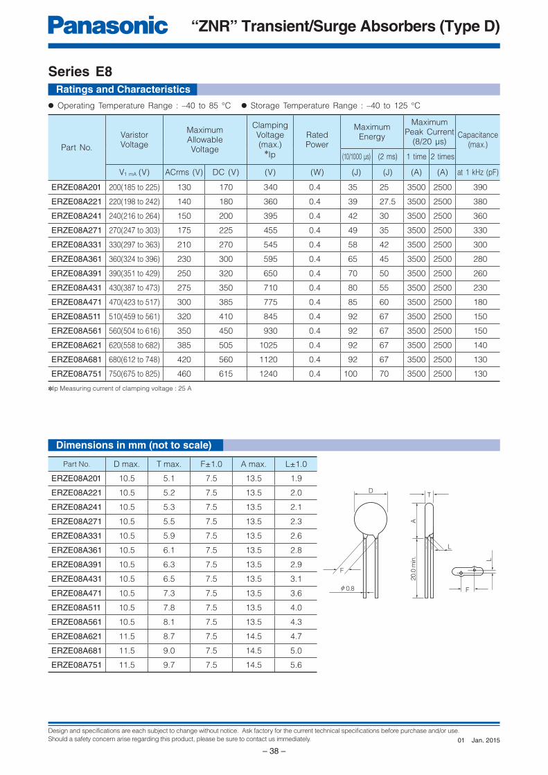
Design and specifications are each subject to change without notice. Ask factory for the current technical specifications before purchase and/or use.
Should a safety concern arise regarding this product, please be sure to contact us immediately.
“ZNR” Transient/Surge Absorbers (Type D)
– 38 –
DT
F
F
A20.0
min
.
f 0.8
L
L
● Operating Temperature Range : –40 to 85 °C ● Storage Temperature Range : –40 to 125 °C
Ratings and Characteristics
Series E8
Dimensions in mm (not to scale)
✽Ip Measuring current of clamping voltage : 25 A
Part No.
VaristorVoltage
MaximumAllowableVoltage
ClampingVoltage(max.)
✽Ip
RatedPower
MaximumEnergy
MaximumPeak Current
(8/20 μs)Capacitance
(max.)
(10/1000 μs) (2 ms) 1 time 2 times
V1 mA (V) ACrms (V) DC (V) (V) (W) (J) (J) (A) (A) at 1 kHz (pF)
ERZE08A201 200(185 to 225) 130 170 340 0.4 35 25 3500 2500 390
ERZE08A221 220(198 to 242) 140 180 360 0.4 39 27.5 3500 2500 380
ERZE08A241 240(216 to 264) 150 200 395 0.4 42 30 3500 2500 360
ERZE08A271 270(247 to 303) 175 225 455 0.4 49 35 3500 2500 330
ERZE08A331 330(297 to 363) 210 270 545 0.4 58 42 3500 2500 300
ERZE08A361 360(324 to 396) 230 300 595 0.4 65 45 3500 2500 280
ERZE08A391 390(351 to 429) 250 320 650 0.4 70 50 3500 2500 260
ERZE08A431 430(387 to 473) 275 350 710 0.4 80 55 3500 2500 230
ERZE08A471 470(423 to 517) 300 385 775 0.4 85 60 3500 2500 180
ERZE08A511 510(459 to 561) 320 410 845 0.4 92 67 3500 2500 150
ERZE08A561 560(504 to 616) 350 450 930 0.4 92 67 3500 2500 150
ERZE08A621 620(558 to 682) 385 505 1025 0.4 92 67 3500 2500 140
ERZE08A681 680(612 to 748) 420 560 1120 0.4 92 67 3500 2500 130
ERZE08A751 750(675 to 825) 460 615 1240 0.4 100 70 3500 2500 130
Part No. D max. T max. F±1.0 A max. L±1.0
ERZE08A201 10.5 5.1 7.5 13.5 1.9
ERZE08A221 10.5 5.2 7.5 13.5 2.0
ERZE08A241 10.5 5.3 7.5 13.5 2.1
ERZE08A271 10.5 5.5 7.5 13.5 2.3
ERZE08A331 10.5 5.9 7.5 13.5 2.6
ERZE08A361 10.5 6.1 7.5 13.5 2.8
ERZE08A391 10.5 6.3 7.5 13.5 2.9
ERZE08A431 10.5 6.5 7.5 13.5 3.1
ERZE08A471 10.5 7.3 7.5 13.5 3.6
ERZE08A511 10.5 7.8 7.5 13.5 4.0
ERZE08A561 10.5 8.1 7.5 13.5 4.3
ERZE08A621 11.5 8.7 7.5 14.5 4.7
ERZE08A681 11.5 9.0 7.5 14.5 5.0
ERZE08A751 11.5 9.7 7.5 14.5 5.6
Jan. 201501

Design and specifications are each subject to change without notice. Ask factory for the current technical specifications before purchase and/or use.
Should a safety concern arise regarding this product, please be sure to contact us immediately.
“ZNR” Transient/Surge Absorbers (Type D)
– 39 –
10000
1000
100
10
120 100 1000
Impulse Width (μs)
Su
rge
Cu
rre
nt (A
)
10000
1 Time
2 Times
10 Times10 2
Times
10 3 Tim
es10 4 Tim
es10 5 Times
10 6 Times
5 min. interval
2 min. interval
10 sec. interval
2 times :
up to 10 times :
up to 106 times :
30
40
50
60708090
100
200
300
400
500
600
700800900
1000
2000 511471431391361331271241221201
511
271
201
10-6 10-5 10-4 10-3 10-2 10-1 100 101 102 103 104
241
221331221331
Vo
lta
ge
(V
)
Current (A)
Max.
Leakage Current
Max. Clamping Voltage
105
Test Current Waveform
10-6 to 10-3 A: Direct Current
10-1 to 104 A: 8/20 μs
471431391361
5000
4000
3000
2000
1000
900
800
700
600
500
400
300
200
Voltag
e (
V)
561
10-6 10-5 10-4 10-3 10-2 10-1 100 101 102 103 104 105
Current (A)
751681621561
Max. Clamping VoltageMax.
Leakage Current
Test Current Waveform
10-6 to 10-3 A: Direct Current
10-1 to 104 A: 8/20 μs
751681621
10000
1000
100
10
20 100 1000 10000
1
Impulse Width (μs)
Surg
e C
urr
ent (A
)
1 Time
2 Times
10 Times10 2
Times
10 3 Tim
es
10 4 Times
10 5 Times
10 6 Times
5 min. interval
2 min. interval
10 sec. interval
2 times :
up to 10 times :
up to 106 times :
Typical Characteristics
Voltage vs. Current Impulse Derating (Relation between impulse width and impulse current multiple)
ERZE08A561 to ERZE08A751
ERZE08A201 to ERZE08A511
ERZE08A561 to ERZE08A751
ERZE08A201 to ERZE08A511
Jan. 201501
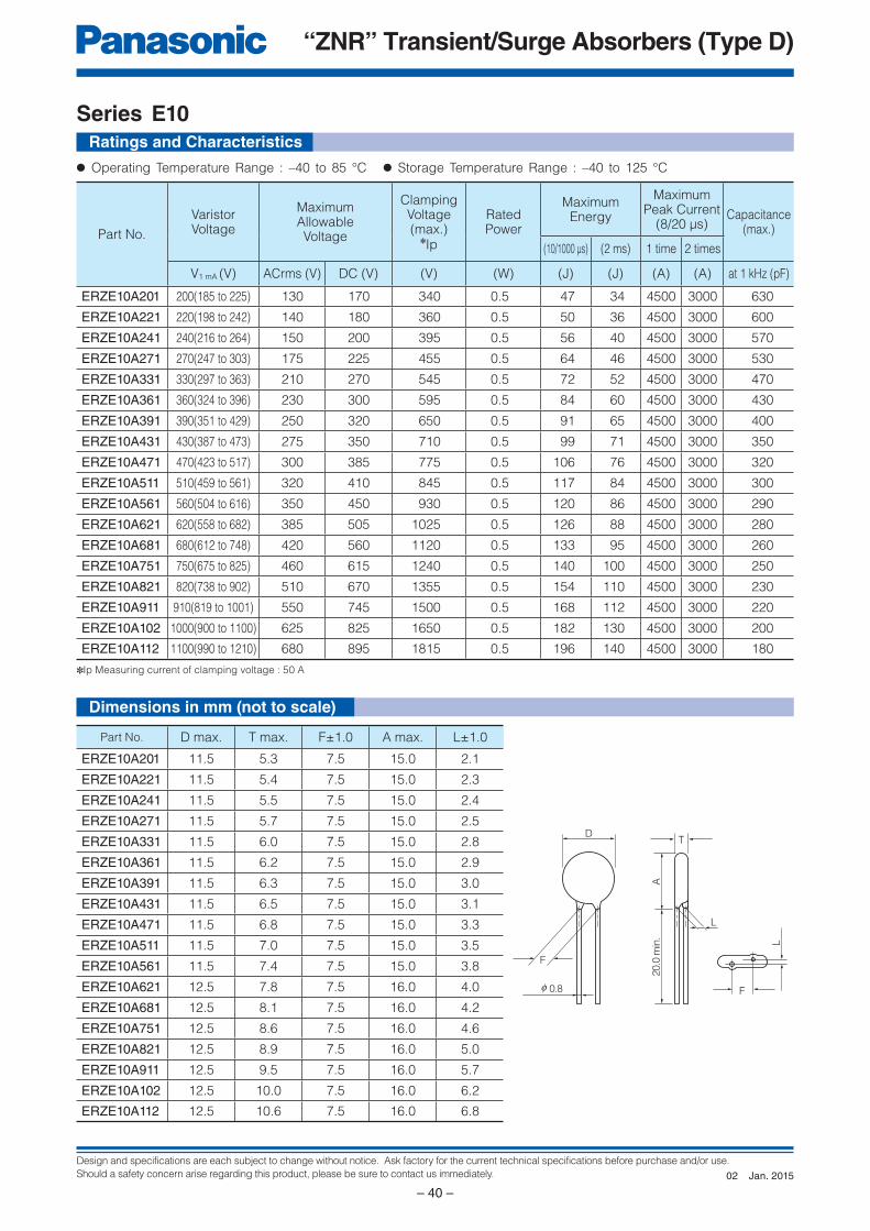
Design and specifications are each subject to change without notice. Ask factory for the current technical specifications before purchase and/or use.
Should a safety concern arise regarding this product, please be sure to contact us immediately.
“ZNR” Transient/Surge Absorbers (Type D)
– 40 –
DT
F
F
A20.0
min
.
f 0.8
L
L
● Operating Temperature Range : –40 to 85 °C ● Storage Temperature Range : –40 to 125 °C
Ratings and Characteristics
Series E10
Dimensions in mm (not to scale)
✽Ip Measuring current of clamping voltage : 50 A
Part No.
VaristorVoltage
MaximumAllowableVoltage
ClampingVoltage(max.)
✽Ip
RatedPower
MaximumEnergy
MaximumPeak Current
(8/20 μs)Capacitance
(max.)
(10/1000 μs) (2 ms) 1 time 2 times
V1 mA (V) ACrms (V) DC (V) (V) (W) (J) (J) (A) (A) at 1 kHz (pF)
ERZE10A201 200(185 to 225) 130 170 340 0.5 47 34 4500 3000 630
ERZE10A221 220(198 to 242) 140 180 360 0.5 50 36 4500 3000 600
ERZE10A241 240(216 to 264) 150 200 395 0.5 56 40 4500 3000 570
ERZE10A271 270(247 to 303) 175 225 455 0.5 64 46 4500 3000 530
ERZE10A331 330(297 to 363) 210 270 545 0.5 72 52 4500 3000 470
ERZE10A361 360(324 to 396) 230 300 595 0.5 84 60 4500 3000 430
ERZE10A391 390(351 to 429) 250 320 650 0.5 91 65 4500 3000 400
ERZE10A431 430(387 to 473) 275 350 710 0.5 99 71 4500 3000 350
ERZE10A471 470(423 to 517) 300 385 775 0.5 106 76 4500 3000 320
ERZE10A511 510(459 to 561) 320 410 845 0.5 117 84 4500 3000 300
ERZE10A561 560(504 to 616) 350 450 930 0.5 120 86 4500 3000 290
ERZE10A621 620(558 to 682) 385 505 1025 0.5 126 88 4500 3000 280
ERZE10A681 680(612 to 748) 420 560 1120 0.5 133 95 4500 3000 260
ERZE10A751 750(675 to 825) 460 615 1240 0.5 140 100 4500 3000 250
ERZE10A821 820(738 to 902) 510 670 1355 0.5 154 110 4500 3000 230
ERZE10A911 910(819 to 1001) 550 745 1500 0.5 168 112 4500 3000 220
ERZE10A102 1000(900 to 1100) 625 825 1650 0.5 182 130 4500 3000 200
ERZE10A112 1100(990 to 1210) 680 895 1815 0.5 196 140 4500 3000 180
Part No. D max. T max. F±1.0 A max. L±1.0
ERZE10A201 11.5 5.3 7.5 15.0 2.1
ERZE10A221 11.5 5.4 7.5 15.0 2.3
ERZE10A241 11.5 5.5 7.5 15.0 2.4
ERZE10A271 11.5 5.7 7.5 15.0 2.5
ERZE10A331 11.5 6.0 7.5 15.0 2.8
ERZE10A361 11.5 6.2 7.5 15.0 2.9
ERZE10A391 11.5 6.3 7.5 15.0 3.0
ERZE10A431 11.5 6.5 7.5 15.0 3.1
ERZE10A471 11.5 6.8 7.5 15.0 3.3
ERZE10A511 11.5 7.0 7.5 15.0 3.5
ERZE10A561 11.5 7.4 7.5 15.0 3.8
ERZE10A621 12.5 7.8 7.5 16.0 4.0
ERZE10A681 12.5 8.1 7.5 16.0 4.2
ERZE10A751 12.5 8.6 7.5 16.0 4.6
ERZE10A821 12.5 8.9 7.5 16.0 5.0
ERZE10A911 12.5 9.5 7.5 16.0 5.7
ERZE10A102 12.5 10.0 7.5 16.0 6.2
ERZE10A112 12.5 10.6 7.5 16.0 6.8
Jan. 201502

Design and specifications are each subject to change without notice. Ask factory for the current technical specifications before purchase and/or use.
Should a safety concern arise regarding this product, please be sure to contact us immediately.
“ZNR” Transient/Surge Absorbers (Type D)
– 41 –
10000
1000
100
10
120 100 1000
Impulse Width (μs)
Su
rge
Cu
rre
nt (A
)
10000
1 Time
2 Times
10 Times
10 2 Tim
es
10 3 Tim
es
10 4 Tim
es10 5 Times
10 6 Times
5 min. interval
2 min. interval
10 sec. interval
2 times :
up to 10 times :
up to 106 times :
30
40
50
60708090
100
200
300
400
500
600
700800900
1000
2000
10-6 10-5 10-4 10-3 10-2 10-1 100 101 102 103 104 105
561
271
241
201
561511471431391361331271241221201
Vo
lta
ge
(V
)
Current (A)
Test Current Waveform
10-6 to 10-3 A: Direct Current
10-1 to 104 A: 8/20 μs
Max. Clamping VoltageMax.
Leakage Current
511471431391361
331221
5000
4000
3000
2000
1000
900
800
700
600
500
400
300
200
112
10-6 10-5 10-4 10-3 10-2 10-1 100 101 102 103 104 105
112102911
821
751
681
621
Voltag
e (
V)
Current (A)
Test Current Waveform
10-6 to 10-3 A: Direct Current
10-1 to 104 A: 8/20 μs
Max. Clamping VoltageMax.
Leakage Current
102911821
751681621
10000
1000
100
10
120 100 1000
Impulse Width (μs)
Surg
e C
urr
ent (A
)
10000
1 Time
2 Times
10 Times10 2
Times
10 3 Tim
es
10 4 Tim
es10 5 Times
10 6 Times
5 min. interval
2 min. interval
10 sec. interval
2 times :
up to 10 times :
up to 106 times :
Typical Characteristics
Voltage vs. Current Impulse Derating (Relation between impulse width and impulse current multiple)
ERZE10A621 to ERZE10A112
ERZE10A201 to ERZE10A561
ERZE10A621 to ERZE10A112
ERZE10A201 to ERZE10A561
Jan. 201502

Design and specifications are each subject to change without notice. Ask factory for the current technical specifications before purchase and/or use.
Should a safety concern arise regarding this product, please be sure to contact us immediately.
“ZNR” Transient/Surge Absorbers (Type D)
– 42 –
DT
F
F
A20.0
min
.
f 0.8
L
L
● Operating Temperature Range : –40 to 85 °C ● Storage Temperature Range : –40 to 125 °C
Ratings and Characteristics
Series E11
Dimensions in mm (not to scale)
✽Ip Measuring current of clamping voltage : 50 A
Part No.
VaristorVoltage
MaximumAllowableVoltage
ClampingVoltage(max.)
✽Ip
RatedPower
MaximumEnergy
MaximumPeak Current
(8/20 μs)Capacitance
(max.)
(10/1000 μs) (2 ms) 1 time 2 times
V1 mA (V) ACrms (V) DC (V) (V) (W) (J) (J) (A) (A) at 1 kHz (pF)
ERZE11A201 200(185 to 225) 130 170 340 0.6 70 50 6000 5000 690
ERZE11A221 220(198 to 242) 140 180 360 0.6 78 55 6000 5000 660
ERZE11A241 240(216 to 264) 150 200 395 0.6 84 60 6000 5000 620
ERZE11A271 270(247 to 303) 175 225 455 0.6 99 70 6000 5000 580
ERZE11A331 330(297 to 363) 210 270 545 0.6 115 80 6000 4500 520
ERZE11A361 360(324 to 396) 230 300 595 0.6 130 90 6000 4500 480
ERZE11A391 390(351 to 429) 250 320 650 0.6 140 100 6000 4500 450
ERZE11A431 430(387 to 473) 275 350 710 0.6 155 110 6000 4500 400
ERZE11A471 470(423 to 517) 300 385 775 0.6 175 125 6000 4500 360
ERZE11A511 510(459 to 561) 320 410 845 0.6 190 136 6000 4500 310
ERZE11A561 560(504 to 616) 350 450 930 0.6 190 136 6000 4500 310
ERZE11A621 620(558 to 682) 385 505 1025 0.6 190 136 5000 4500 300
ERZE11A681 680(612 to 748) 420 560 1120 0.6 190 136 5000 4500 290
ERZE11A751 750(675 to 825) 460 615 1240 0.6 210 150 5000 4500 280
ERZE11A821 820(738 to 902) 510 670 1355 0.6 235 165 5000 4500 260
ERZE11A911 910(819 to 1001) 550 745 1500 0.6 255 180 5000 4500 240
ERZE11A102 1000(900 to 1100) 625 825 1650 0.6 280 200 5000 4500 220
ERZE11A112 1100(990 to 1210) 680 895 1815 0.6 310 220 5000 4500 200
Part No. D max. T max. F±1.0 A max. L±1.0
ERZE11A201 13.0 5.2 7.5 17.0 1.9
ERZE11A221 13.0 5.3 7.5 17.0 2.0
ERZE11A241 13.0 5.4 7.5 17.0 2.1
ERZE11A271 13.0 5.6 7.5 17.0 2.3
ERZE11A331 13.0 5.9 7.5 17.0 2.6
ERZE11A361 13.0 6.1 7.5 17.0 2.8
ERZE11A391 13.0 6.2 7.5 17.0 2.9
ERZE11A431 13.0 6.4 7.5 17.0 3.1
ERZE11A471 13.0 6.6 7.5 17.0 3.3
ERZE11A511 13.0 6.8 7.5 17.0 3.5
ERZE11A561 13.0 7.2 7.5 17.0 3.8
ERZE11A621 14.0 7.5 7.5 18.0 4.2
ERZE11A681 14.0 7.8 7.5 18.0 4.5
ERZE11A751 14.0 8.2 7.5 18.0 4.9
ERZE11A821 14.0 8.5 7.5 18.0 5.2
ERZE11A911 14.0 9.0 7.5 18.0 5.7
ERZE11A102 14.0 9.5 7.5 18.0 6.2
ERZE11A112 14.0 10.1 7.5 18.0 6.8
Jan. 201501

Design and specifications are each subject to change without notice. Ask factory for the current technical specifications before purchase and/or use.
Should a safety concern arise regarding this product, please be sure to contact us immediately.
“ZNR” Transient/Surge Absorbers (Type D)
– 43 –
10000
1000
100
10
120 100 1000
Impulse Width (μs)10000
Su
rge
Cu
rre
nt (A
)
5 min. interval
2 min. interval
10 sec. interval
2 times :
up to 10 times :
up to 106 times :
1 Time
2 Time10 Tim
es
10 2 Times
10 3 Times
10 4 Times10 5 Times10 6 Times
30
40
50
60708090
100
200
300
400
500
600
700800900
1000
2000
Vo
lta
ge
(V
)
10-6 10-5 10-4 10-3 10-2 10-1 100 101 102 103 104 105
Current (A)
511
471431391361
331221
271
241
201
511471431391361331271241221201
Max.
Leakage Current
Max. Clamping Voltage
Test Current Waveform
10-6 to 10-3 A: Direct Current
10-1 to 104 A: 8/20 μs
5000
4000
3000
2000
1000
900
800
700
600
500
400
300
200
Voltag
e (
V)
112
112
561
10-6 10-5 10-4 10-3 10-2 10-1 100 101 102 103 104 105
Current (A)
621
561
102911821751681
Max.
Leakage Current
Max. Clamping Voltage
Test Current Waveform
10-6 to 10-3 A: Direct Current
10-1 to 104 A: 8/20 μs
102911821
751681621
10000
1000
100
10
20 100 1000 10000
1
5 min. interval
2 min. interval
10 sec. interval
2 times :
up to 10 times :
up to 106 times :
Surg
e C
urr
ent (A
)
Impulse Width (μs)
1 Time
2 Times
10 Times
10 2 Tim
es
10 3 Tim
es10 4 Tim
es
10 6 Times
Typical Characteristics
Voltage vs. Current Impulse Derating (Relation between impulse width and impulse current multiple)
ERZE11A561 to ERZE11A112
ERZE11A201 to ERZE11A511
ERZE11A561 to ERZE11A112
ERZE11A201 to ERZE11A511
Jan. 201501

Design and specifications are each subject to change without notice. Ask factory for the current technical specifications before purchase and/or use.
Should a safety concern arise regarding this product, please be sure to contact us immediately.
“ZNR” Transient/Surge Absorbers (Type D)
– 44 –
F
L
DT
F
A20.0
min
.
f 1.0
L
● Operating Temperature Range : –40 to 85 °C ● Storage Temperature Range : –40 to 125 °C
Ratings and Characteristics
Series E14
Dimensions in mm (not to scale)
✽Ip Measuring current of clamping voltage : 100 A
Part No. D max. T max. F±1.0 A max. L±1.0
ERZE14A201 16.5 5.2 10.0 20.0 2.1
ERZE14A221 16.5 5.3 10.0 20.0 2.2
ERZE14A241 16.5 5.4 10.0 20.0 2.3
ERZE14A271 16.5 5.6 10.0 20.0 2.5
ERZE14A331 16.5 5.9 10.0 20.0 2.8
ERZE14A361 16.5 6.1 10.0 20.0 3.0
ERZE14A391 16.5 6.2 10.0 20.0 3.1
ERZE14A431 16.5 6.4 10.0 20.0 3.3
ERZE14A471 16.5 6.6 10.0 20.0 3.5
ERZE14A511 16.5 6.8 10.0 20.0 3.7
ERZE14A561 16.5 7.2 10.0 20.0 4.0
ERZE14A621 17.5 7.5 10.0 20.5 4.4
ERZE14A681 17.5 7.8 10.0 20.5 4.7
ERZE14A751 17.5 8.2 10.0 20.5 5.1
ERZE14A821 17.5 8.5 10.0 20.5 5.4
ERZE14A911 17.5 9.0 10.0 20.5 5.9
ERZE14A102 17.5 9.5 10.0 20.5 6.4
ERZE14A112 17.5 10.1 10.0 20.5 7.2
Part No.
VaristorVoltage
MaximumAllowableVoltage
ClampingVoltage(max.)
✽Ip
RatedPower
MaximumEnergy
MaximumPeak Current
(8/20 μs)Capacitance
(max.)
(10/1000 μs) (2 ms) 1 time 2 times
V1 mA (V) ACrms (V) DC (V) (V) (W) (J) (J) (A) (A) at 1 kHz (pF)
ERZE14A201 200(185 to 225) 130 170 340 1.0 140 100 10000 7000 1300
ERZE14A221 220(198 to 242) 140 180 360 1.0 155 110 10000 7000 1200
ERZE14A241 240(216 to 264) 150 200 395 1.0 168 120 10000 7000 1100
ERZE14A271 270(247 to 303) 175 225 455 1.0 190 135 10000 7000 1000
ERZE14A331 330(297 to 363) 210 270 545 1.0 228 160 10000 6500 900
ERZE14A361 360(324 to 396) 230 300 595 1.0 255 180 10000 6500 900
ERZE14A391 390(351 to 429) 250 320 650 1.0 275 195 10000 6500 800
ERZE14A431 430(387 to 473) 275 350 710 1.0 303 215 10000 6500 800
ERZE14A471 470(423 to 517) 300 385 775 1.0 350 250 10000 6500 750
ERZE14A511 510(459 to 561) 320 410 845 1.0 382 273 10000 6500 700
ERZE14A561 560(504 to 616) 350 450 930 1.0 382 273 10000 6500 700
ERZE14A621 620(558 to 682) 385 505 1025 1.0 382 273 7500 6500 650
ERZE14A681 680(612 to 748) 420 560 1120 1.0 382 273 7500 6500 600
ERZE14A751 750(675 to 825) 460 615 1240 1.0 420 300 7500 6500 530
ERZE14A821 820(738 to 902) 510 670 1355 1.0 460 325 7500 6500 500
ERZE14A911 910(819 to 1001) 550 745 1500 1.0 510 360 7500 6500 400
ERZE14A102 1000(900 to 1100) 625 825 1650 1.0 565 400 7500 6500 400
ERZE14A112 1100(990 to 1210) 680 895 1815 1.0 620 440 7500 6500 350
Jan. 201502
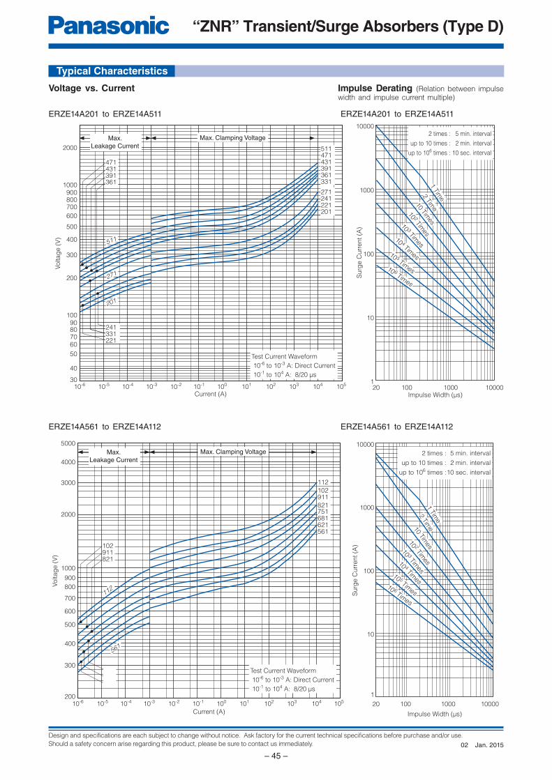
Design and specifications are each subject to change without notice. Ask factory for the current technical specifications before purchase and/or use.
Should a safety concern arise regarding this product, please be sure to contact us immediately.
“ZNR” Transient/Surge Absorbers (Type D)
– 45 –
10000
1000
100
Su
rge
Cu
rre
nt (A
)
10
120 100 1000
Impulse Width (μs)10000
5 min. interval
2 min. interval
10 sec. interval
2 times :
up to 10 times :
up to 106 times :
1 Time2 Tim
e
10 Times
10 2 Times
10 3 Times
10 4 Times10 5 Tim
es10 6 Times
30
40
50
60708090
100
200
300
400
500
600
700800900
1000
2000
511
271
201
10-6 10-5 10-4 10-3 10-2 10-1 100 101 102 103 104 105
Current (A)
511471431391361331
271241221201
Max.
Leakage Current
Max. Clamping Voltage
Test Current Waveform
10-6 to 10-3 A: Direct Current
10-1 to 104 A: 8/20 μs
Vo
lta
ge
(V
)
471431391361
241331221
5000
4000
3000
2000
1000
900
800
700
600
500
400
300
200
112
751681621
561
10-6 10-5 10-4 10-3 10-2 10-1 100 101 102 103 104 105
Current (A)
112
102911
751681621561
821
Voltag
e (
V)
Test Current Waveform
10-6 to 10-3 A: Direct Current
10-1 to 104 A: 8/20 μs
Max.
Leakage Current
Max. Clamping Voltage
102911821
10000
1000
100
10
20 100 1000 10000
1
Surg
e C
urr
ent (A
)
Impulse Width (μs)
5 min. interval
2 min. interval
10 sec. interval
2 times :
up to 10 times :
up to 106 times :
1 Time
2 Time10 Tim
es
10 2 Times
10 3 Times
10 4 Times
10 5 Times
10 6 Times
Typical Characteristics
Voltage vs. Current Impulse Derating (Relation between impulse width and impulse current multiple)
ERZE14A561 to ERZE14A112
ERZE14A201 to ERZE14A511
ERZE14A561 to ERZE14A112
ERZE14A201 to ERZE14A511
Jan. 201502

Design and specifications are each subject to change without notice. Ask factory for the current technical specifications before purchase and/or use.
Should a safety concern arise regarding this product, please be sure to contact us immediately.
“ZNR” Transient/Surge Absorbers (Type D)
– 46 –
D T✽✽
L✽F
fd
AB
D T✽✽
L✽F
fd
C
A
B
✽✽✽
C
Ratings and Characteristics
Ratings and Characteristics
Dimensions in mm (not to scale)
Dimensions in mm (not to scale)
Straight Leads Cut Type (Bulk Type)
✽ Refer to bulk standard type part no. (P34 to P43).
✽ Refer to bulk standard type part no. (P34 to P43).
notes ✽ Dimension “L”: Conforms to each individtual specification. ✽✽ Dimension “T”: Conforms to each individual specification.
Crimped Leads Cut Type (Bulk Type)
notes ✽ Dimension “L”: Conforms to each individual specification. ✽✽ Dimension “T”: Conforms to each individual specification. ✽✽✽ Resin extenyions : No resin below the center of the hook.
Unit : mm
Unit : mm
Series E5 E7 E8 E10 E11Varistor Voltage
Symbol 201 to 471 201 to 511 561 621 201 to 561 621 to 751 201 to 561 621 to 112 201 to 561 621 to 112
D 7.0 max. 9.0 max. 9.0 max. 10.0 max. 10.5 max. 11.5 max. 11.5 max. 12.5 max. 13.0 max. 14.0 max.
A 10.0 max. 12.5 max. 13.5 max. 13.5 max. 13.5 max. 14.5 max. 15.0 max. 16.0 max. 17.0 max. 18.0 max.
F 5.0±1.0 7.5±1.0 7.5±1.0 7.5±1.0 7.5±1.0 7.5±1.0 7.5±1.0 7.5±1.0 7.5±1.0 7.5±1.0
fd 0.60+0.06 0.80+0.08 0.80+0.08 0.80+0.08 0.80+0.08 0.80+0.08 0.80+0.08 0.80+0.08 0.80+0.08 0.80+0.08
B 4.0±1.0 4.0±1.0 4.0±1.0 4.0±1.0 4.0±1.0 4.0±1.0 4.0±1.0 4.0±1.0 4.0±1.0 4.0±1.0StandardProductsPart No.
ERZE05A□□□CS ERZE07A□□□CS ERZE08A□□□CS ERZE10A□□□CS ERZE11A□□□CS
–0.05–0.05–0.05 –0.05–0.05–0.05–0.05–0.05 –0.05–0.05
Series E5 E7 E8 E10 E11Varistor Voltage
Symbol 201 to 471 201 to 511 561 621 201 to 561 621 to 751 201 to 561 621 to 681 751 to 112 201 to 561 621 to 112
D 7.0 max. 9.0 max. 9.0 max. 10.0 max. 10.5 max. 11.5 max. 11.5 max. 12.5 max. 12.5 max. 13.0 max. 14.0 max.
A 13.0 max. 15.5 max. 16.5 max. 16.5 max. 17.0 max. 18.0 max. 18.0 max. 19.5 max. 20.5 max. 20.5 max. 21.5 max.
C 1.2±0.4 1.4±0.4 1.4±0.4 1.4±0.4 1.4±0.4 1.4±0.4 1.4±0.4 1.4±0.4 1.4±0.4 1.4±0.4 1.4±0.4
F 5.0±1.0 7.5±1.0 7.5±1.0 7.5±1.0 7.5±1.0 7.5±1.0 7.5±1.0 7.5±1.0 7.5±1.0 7.5±1.0 7.5±1.0
fd 0.60+0.06 0.80+0.08 0.80+0.08 0.80+0.08 0.80+0.08 0.80+0.08 0.80+0.08 0.80+0.08 0.80+0.08 0.80+0.08 0.80+0.08
B 4.0±1.0 4.0±1.0 4.0±1.0 4.0±1.0 4.0±1.0 4.0±1.0 4.0±1.0 4.0±1.0 4.0±1.0 4.0±1.0 4.0±1.0StandardProductsPart No.
ERZE05B□□□CS ERZE07B□□□CS ERZE08B□□□CS ERZE10B□□□CS ERZE11B□□□CS
–0.05–0.05–0.05 –0.05–0.05 –0.05 –0.05 –0.05–0.05–0.05 –0.05
Apr. 201705

Design and specifications are each subject to change without notice. Ask factory for the current technical specifications before purchase and/or use.
Should a safety concern arise regarding this product, please be sure to contact us immediately.
“ZNR” Transient/Surge Absorbers (Type D)
– 47 –
P0
P2 P
P1
f D0
f D
f d
F
L
A
W
t
W0
W2
W1
HH0
T✽
△h
F1
Position of H0 dimension
Position of F1 dimension
Ratings and Characteristics
Taping Dimensions in mm (not to scale)
✽ Refer to bulk standard type part no. (P34 to P43).
✽ Dimension “T”: Conforms to each individual specification.
Taping Specifi cations for Automated Assembly(Straight Leads and Taping)
Unit : mm
Series E5 E7 E8 E10 E11Varistor Voltage 201 to 471 201 to 271 331 to 551 561 621 201 to 221 241 to 561 621 to 751 201 to 221 241 to 561 621 to 112 201 to 221 241 to 561 621 to 112
P 12.7±1.0 15.0±1.0 15.0±1.0 15.0±1.0 15.0±1.0 15.0±1.0 15.0±1.0 15.0±1.0 15.0±1.0 15.0±1.0 15.0±1.0 15.0±1.0 15.0±1.0 15.0±1.0
P0 12.7±0.3 15.0±0.3 15.0±0.3 15.0±0.3 15.0±0.3 15.0±0.3 15.0±0.3 15.0±0.3 15.0±0.3 15.0±0.3 15.0±0.3 15.0±0.3 15.0±0.3 15.0±0.3
P1 3.85±0.70 3.75±0.70 3.75±0.70 3.75±0.70 3.75±0.70 3.75±0.70 3.75±0.70 3.75±0.70 3.75±0.70 3.75±0.70 3.75±0.70 3.75±0.70 3.75±0.70 3.75±0.70
P2 6.36±1.30 7.5±1.37.5±1.37.5±1.37.5±1.37.5±1.37.5±1.37.5±1.37.5±1.37.5±1.37.5±1.37.5±1.37.5±1.37.5±1.3
fd 0.60+0.06 0.80+0.08 0.80+0.08 0.80+0.08 0.80+0.08 0.80+0.08 0.80+0.08 0.80+0.08 0.80+0.08 0.80+0.08 0.80+0.08 0.80+0.08 0.80+0.08 0.80+0.08
F 5.0±0.5 7.5±0.5 7.5±0.5 7.5±0.5 7.5±0.5 7.5±0.5 7.5±0.5 7.5±0.5 7.5±0.5 7.5±0.5 7.5±0.5 7.5±0.5 7.5±0.5 7.5±0.5
△h 0±2 0±2 0±2 0±2 0±2 0±2 0±2 0±2 0±2 0±2 0±2 0±2 0±2 0±2
W 18.0+1.0 18.0+1.0 18.0+1.0 18.0+1.0 18.0+1.0 18.0+1.0 18.0+1.0 18.0+1.0 18.0+1.0 18.0+1.0 18.0+1.0 18.0+1.0 18.0+1.0 18.0+1.0
W0 5.0 min. 5.0 min. 5.0 min. 5.0 min. 5.0 min. 5.0 min. 5.0 min. 5.0 min. 5.0 min. 5.0 min. 5.0 min. 5.0 min. 5.0 min. 5.0 min.
W1 9.0±0.5 9.0±0.5 9.0±0.5 9.0±0.5 9.0±0.5 9.0±0.5 9.0±0.5 9.0±0.5 9.0±0.5 9.0±0.5 9.0±0.5 9.0±0.5 9.0±0.5 9.0±0.5
W2 3.0 max. 3.0 max. 3.0 max. 3.0 max. 3.0 max. 3.0 max. 3.0 max. 3.0 max. 3.0 max. 3.0 max. 3.0 max. 3.0 max. 3.0 max. 3.0 max.
H Approx. 22 Approx. 22 Approx. 22 Approx. 22 Approx. 22 Approx. 22 Approx. 22 Approx. 22 Approx. 22 Approx. 22 Approx. 22 Approx. 22 Approx. 22 Approx. 22
H0 17.0±0.5 18.0+2.0 —— —— —— 18.0+2.0 —— —— 18.0+2.0 —— —— 18.0+2.0 —— ——
F1 —— —— 16.00+0.75 16.00+0.75 16.00+0.75 —— 16.00+0.75 16.00+0.75 —— 16.00+0.75 16.00+0.75 —— 16.00+0.75 16.00+0.75
fD0 f 4.0±0.2 f 4.0±0.2 f 4.0±0.2 f 4.0±0.2 f 4.0±0.2 f 4.0±0.2 f 4.0±0.2 f 4.0±0.2 f 4.0±0.2 f 4.0±0.2 f 4.0±0.2 f 4.0±0.2 f 4.0±0.2 f 4.0±0.2
t 0.6±0.3 0.6±0.3 0.6±0.3 0.6±0.3 0.6±0.3 0.6±0.3 0.6±0.3 0.6±0.3 0.6±0.3 0.6±0.3 0.6±0.3 0.6±0.3 0.6±0.3 0.6±0.3
L 11.0 max. 11.0 max. 11.0 max. 11.0 max. 11.0 max. 11.0 max. 11.0 max. 11.0 max. 11.0 max. 11.0 max. 11.0 max. 11.0 max. 11.0 max. 11.0 max.
fD 7.0 max. 9.0 max. 9.0 max. 9.0 max. 10.0 max. 10.5 max. 10.5 max. 11.5 max. 11.5 max. 11.5 max. 12.5 max. 13.0 max. 13.0 max. 14.0 max.
A 10.0 max. 12.5 max. 12.5 max. 13.5 max. 13.5 max. 13.5 max. 13.5 max. 14.5 max. 15.0 max. 15.0 max. 16.0 max. 17.0 max. 17.0 max. 18.0 max.StandardProductsPart No.
ERZE05E□□□ ERZE07E□□□ ERZE08E□□□ ERZE10E□□□ ERZE11E□□□
–0.05 –0.05 –0.05
–0.5 –0.5 –0.5 –0.5 –0.5 –0.5
0
–0.50 –0.50
0
–0.50 –0.50
Symbol
–0.05 –0.05
–0.5 –0.5 –0.5 –0.5 –0.5
0
–0.50 –0.50 –0.50
–0.05 –0.05 –0.05 –0.05 –0.05 –0.05 –0.05–0.05–0.05
–0.5–0.5–0.5
0
–0.50 –0.50
Apr. 201705
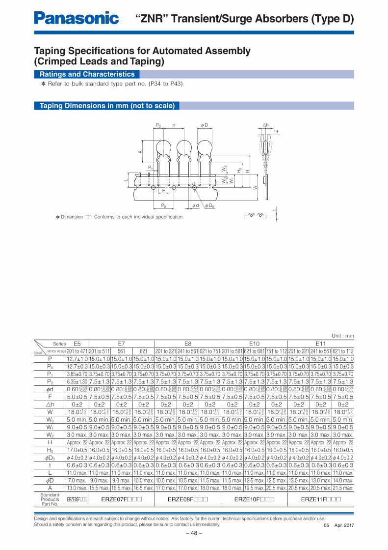
Design and specifications are each subject to change without notice. Ask factory for the current technical specifications before purchase and/or use.
Should a safety concern arise regarding this product, please be sure to contact us immediately.
“ZNR” Transient/Surge Absorbers (Type D)
– 48 –
P0
P2 P
P1
f D0
f D
f d
F
L
A
W
t
W0
W2
W1
HH0
T✽
△h
✽ Dimension “T”: Conforms to each individual specifi cation.
Ratings and Characteristics
Taping Dimensions in mm (not to scale)
✽ Refer to bulk standard type part no. (P34 to P43).
Taping Specifi cations for Automated Assembly(Crimped Leads and Taping)
Unit : mm
Series E5 E7 E8 E10 E11Varistor Voltage 201 to 471 201 to 511 561 621 201 to 221 241 to 561 621 to 751 201 to 561 621 to 681 751 to 112 201 to 221 241 to 561 621 to 112
P 12.7±1.0 15.0±1.0 15.0±1.0 15.0±1.0 15.0±1.0 15.0±1.0 15.0±1.0 15.0±1.0 15.0±1.0 15.0±1.0 15.0±1.0 15.0±1.0 15.0±1.0
P0 12.7±0.3 15.0±0.3 15.0±0.3 15.0±0.3 15.0±0.3 15.0±0.3 15.0±0.3 15.0±0.3 15.0±0.3 15.0±0.3 15.0±0.3 15.0±0.3 15.0±0.3
P1 3.85±0.70 3.75±0.70 3.75±0.70 3.75±0.70 3.75±0.70 3.75±0.70 3.75±0.70 3.75±0.70 3.75±0.70 3.75±0.70 3.75±0.70 3.75±0.70 3.75±0.70
P2 6.35±1.30 7.5±1.3 7.5±1.3 7.5±1.3 7.5±1.3 7.5±1.3 7.5±1.3 7.5±1.3 7.5±1.3 7.5±1.3 7.5±1.3 7.5±1.3 7.5±1.3
fd 0.60+0.06 0.80+0.08 0.80+0.08 0.80+0.08 0.80+0.08 0.80+0.08 0.80+0.08 0.80+0.08 0.80+0.08 0.80+0.08 0.80+0.08 0.80+0.08 0.80+0.08
F 5.0±0.5 7.5±0.5 7.5±0.5 7.5±0.5 7.5±0.5 7.5±0.5 7.5±0.5 7.5±0.5 7.5±0.5 7.5±0.5 7.5±0.5 7.5±0.5 7.5±0.5
△h 0±2 0±2 0±2 0±2 0±2 0±2 0±2 0±2 0±2 0±2 0±2 0±2 0±2
W 18.0+1.0 18.0+1.0 18.0+1.0 18.0+1.0 18.0+1.0 18.0+1.0 18.0+1.0 18.0+1.0 18.0+1.0 18.0+1.0 18.0+1.0 18.0+1.0 18.0+1.0
W0 5.0 min. 5.0 min. 5.0 min. 5.0 min. 5.0 min. 5.0 min. 5.0 min. 5.0 min. 5.0 min. 5.0 min. 5.0 min. 5.0 min. 5.0 min.
W1 9.0±0.5 9.0±0.5 9.0±0.5 9.0±0.5 9.0±0.5 9.0±0.5 9.0±0.5 9.0±0.5 9.0±0.5 9.0±0.5 9.0±0.5 9.0±0.5 9.0±0.5
W2 3.0 max. 3.0 max. 3.0 max. 3.0 max. 3.0 max. 3.0 max. 3.0 max. 3.0 max. 3.0 max. 3.0 max. 3.0 max. 3.0 max. 3.0 max.
H Approx. 22 Approx. 22 Approx. 22 Approx. 22 Approx. 22 Approx. 22 Approx. 22 Approx. 22 Approx. 22 Approx. 22 Approx. 22 Approx. 22 Approx. 22
H0 17.0±0.5 16.0±0.5 16.0±0.5 16.0±0.5 16.0±0.5 16.0±0.5 16.0±0.5 16.0±0.5 16.0±0.5 16.0±0.5 16.0±0.5 16.0±0.5 16.0±0.5
fD0 f 4.0±0.2 f 4.0±0.2 f 4.0±0.2 f 4.0±0.2 f 4.0±0.2 f 4.0±0.2 f 4.0±0.2 f 4.0±0.2 f 4.0±0.2 f 4.0±0.2 f 4.0±0.2 f 4.0±0.2 f 4.0±0.2
t 0.6±0.3 0.6±0.3 0.6±0.3 0.6±0.3 0.6±0.3 0.6±0.3 0.6±0.3 0.6±0.3 0.6±0.3 0.6±0.3 0.6±0.3 0.6±0.3 0.6±0.3
L 11.0 max. 11.0 max. 11.0 max. 11.0 max. 11.0 max. 11.0 max. 11.0 max. 11.0 max. 11.0 max. 11.0 max. 11.0 max. 11.0 max. 11.0 max.
fD 7.0 max. 9.0 max. 9.0 max. 10.0 max. 10.5 max. 10.5 max. 11.5 max. 11.5 max. 12.5 max. 12.5 max. 13.0 max. 13.0 max. 14.0 max.
A 13.0 max. 15.5 max. 16.5 max. 16.5 max. 17.0 max. 17.0 max. 18.0 max. 18.0 max. 19.5 max. 20.5 max. 20.5 max. 20.5 max. 21.5 max.StandardProductsPart No.
ERZE05F□□□ ERZE07F□□□ ERZE08F□□□ ERZE10F□□□ ERZE11F□□□
–0.05 –0.05 –0.05 –0.05 –0.05 –0.05
–0.5 –0.5 –0.5 –0.5 –0.5 –0.5
Symbol
–0.05–0.05–0.05
–0.5 –0.5 –0.5 –0.5
–0.05 –0.05
–0.5
–0.05
–0.5
–0.05
–0.5
Apr. 201705

Design and specifications are each subject to change without notice. Ask factory for the current technical specifications before purchase and/or use.
Should a safety concern arise regarding this product, please be sure to contact us immediately.
“ZNR” Transient/Surge Absorbers (Type D)
– 49 –
Application Note for Safety Standards (For Series E)
● Approvals products lists in "Reference Guide to Standard Products"● UL and VDE : Registered in "Type Name" , it isn’t registered in "Panasonic Part No."● CQC : Registered in "Panasonic Part No."● "Rated Voltages" are specifi ed for UL recognized components in list shown below.
✽: 5 series is blank, 7 series is 7, 8 series is 8, 10 series is 10, 11 series is 11, 14 series is 14
Type Name
Maximum Allowable Voltage Rated Voltage (Vrms)
ACrms (V) DC (V) UL1449
E✽201 130 170 118
E✽221 140 180 127
E✽241 150 200 136
E✽271 175 225 159
E✽331 210 270 189
E✽361 230 300 209
E✽391 250 320 227
E✽431 275 350 250
E✽471 300 385 272
E✽511 320 410 291
E✽561 350 450 320
E✽621 385 505 350
E✽681 420 560 381
E✽751 460 615 418
E✽821 510 670 463
E✽911 550 745 500
E✽102 625 825 568
E✽112 680 895 600
The AC Rated Voltage and Maximum Allowable Voltage
Jan. 201503
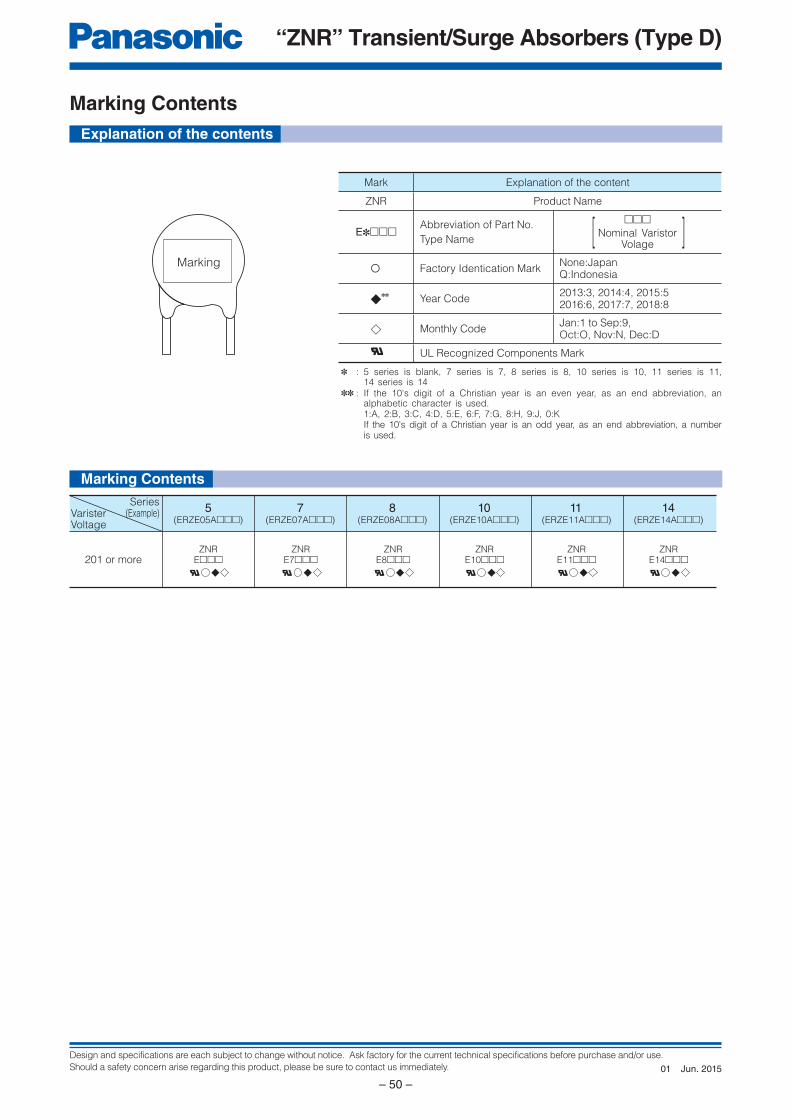
Design and specifications are each subject to change without notice. Ask factory for the current technical specifications before purchase and/or use.
Should a safety concern arise regarding this product, please be sure to contact us immediately.
“ZNR” Transient/Surge Absorbers (Type D)
– 50 –
5(ERZE05A□□□)
201 or more
7(ERZE07A□□□)
8(ERZE08A□□□)
10(ERZE10A□□□)
11(ERZE11A□□□)
14(ERZE14A□□□)
VaristerVoltage
Series(Example)
ZNRE□□□
ZNRE7□□□
ZNRE8□□□
ZNRE10□□□
ZNRE11□□□
ZNRE14□□□
Marking
Marking Contents
✽ : 5 series is blank, 7 series is 7, 8 series is 8, 10 series is 10, 11 series is 11,14 series is 14
✽✽ : If the 10's digit of a Christian year is an even year, as an end abbreviation, an alphabetic character is used.
1:A, 2:B, 3:C, 4:D, 5:E, 6:F, 7:G, 8:H, 9:J, 0:K If the 10's digit of a Christian year is an odd year, as an end abbreviation, a number
is used.
Mark Explanation of the content
ZNR Product Name
E✽□□□Abbreviation of Part No.
Type Name
□□□Nominal Varistor
Volage
M Factory Identication MarkNone:JapanQ:Indonesia
◆✽✽Year Code
2013:3, 2014:4, 2015:52016:6, 2017:7, 2018:8
◇ Monthly CodeJan:1 to Sep:9,Oct:O, Nov:N, Dec:D
UL Recognized Components Mark
[ ]
Explanation of the contents
Marking Contents
Jun. 201501

Design and specifications are each subject to change without notice. Ask factory for the current technical specifications before purchase and/or use.
Should a safety concern arise regarding this product, please be sure to contact us immediately.
“ZNR” Transient/Surge Absorbers (Type D)
– 51 –
Performance Characteristics (Series E)
Characteristics Test Methods/Description Specifi cations
Standard Test ConditionElectrical measurements (initial/after tests) shall be conducted at tem per a ture of 5 to 35 °C, relative humidity of maximum 85 %
———
Ele
ctr
ical
Varistor VoltageThe voltage betwen two terminals with the specifi ed measuring cur rent 1mA DC applied is called V1 or V1mA. The mea sure ment shall be made as fast as pos si ble to avoid heat affection.
To meet thespecifi ed value.
MaximumAllowable Volt age
The maximum sinusoidal RMS voltage or maximum DC voltage that can be applied continuously.
Clamping Voltage
The maximum voltage between two terminals with the specifi ed stan dard impulse current (8/20 μs) illustrated below applied.
Time
100 90
50
10 0
Curr
ent(
%)
8 μs20 μs
Rated PowerThe power that can be applied in the specifi ed ambienttemperature.
Maximum EnergyThe maximum energy within the varistor voltage change of ±10 % when a single impulse current of 2 ms or 10/1000 μs is ap plied.
MaximumPeak
Current(Withstanding
SurgeCurrent)
2 timesThe maximum current within the varistor voltage change of ±10 % when a standard im pulse current of 8/20 μs is applied two times with an interval of 5 minutes.
1 timeThe maximum current within the varistor voltage change of ±10 % with a single standard im pulse current of 8/20 μs is ap plied.
Temperature Co ef fi cient of Varistor Voltage
V1mA at 85 °C – V1mA at 25 °C×
1× 100 (%/°C)
V1mA at 25 °C 600 to -0.05 %/°C max.
CapacitanceCapacitance shall be measured at 1 kHz ±10 %, 1 Vrms max. (1 MHz ±10 % below 100 pF), 0 V bias and 20±2 °C.
To meet thespecifi ed value
Withstanding Voltage(Body Insulation)
AC 1500 Vrms shall be applied between both terminals of the spec i men connected together and met al foil closely wrapped round its body for 1 minute.
No breakdown
Impulse Life
The change of VC shall be measured after the impulse current list ed be low is applied 10000 or 100000 times con tin u ous ly with the interval of 10 seconds at room temperature.
Item Impulse Life (I) Impulse Life (II)
Times ×104 Times ×10
5 Times
Part No. Current Impulse Current
ERZE05A201 to ERZE05A471 50 A (8/20 μs) 35 A (8/20 μs)
ERZE07A201 to ERZE07A621 100 A (8/20 μs) 70 A (8/20 μs)
ERZE08A201 to ERZE08A751 150 A (8/20 μs) 85 A (8/20 μs)
ERZE10A201 to ERZE10A112 170 A (8/20 μs) 90 A (8/20 μs)
ERZE11A201 to ERZE11A112 200 A (8/20 μs) 110 A (8/20 μs)
ERZE14A201 to ERZE14A112 250 A (8/20 μs) 120 A (8/20 μs)
ΔV1mA/V1mA < 0 to 20 %
Jan. 201504
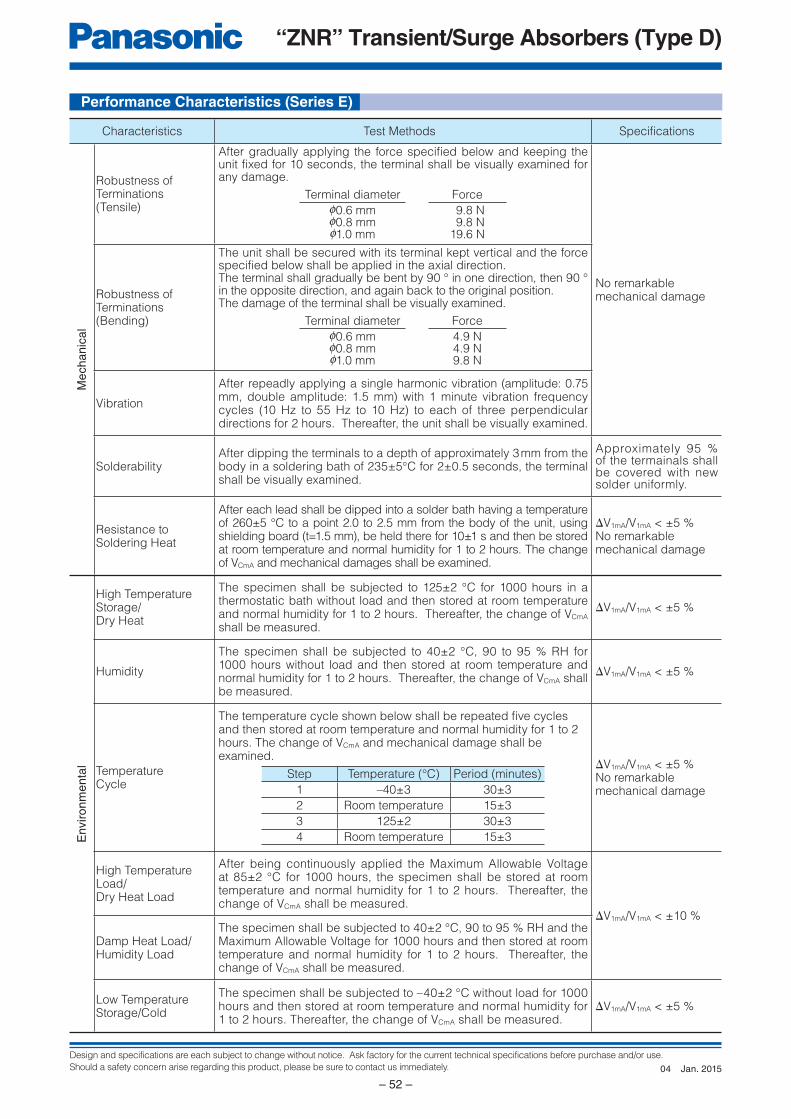
Design and specifications are each subject to change without notice. Ask factory for the current technical specifications before purchase and/or use.
Should a safety concern arise regarding this product, please be sure to contact us immediately.
“ZNR” Transient/Surge Absorbers (Type D)
– 52 –
Characteristics Test Methods Specifi cations
Me
ch
an
ica
l
Robustness ofTerminations(Tensile)
After gradually applying the force specifi ed below and keeping the unit fi xed for 10 seconds, the terminal shall be visually examined for any damage.
Terminal diameter Force
00.6 mm00.8 mm01.0 mm
9.8 N 9.8 N19.6 N
No remarkablemechanical damageRobustness of
Terminations(Bending)
The unit shall be secured with its terminal kept vertical and the force specifi ed below shall be applied in the axial direction.The terminal shall gradually be bent by 90 ° in one direction, then 90 ° in the opposite direction, and again back to the original po si tion.The damage of the terminal shall be visually examined.
Terminal diameter Force
00.6 mm00.8 mm01.0 mm
4.9 N4.9 N9.8 N
Vibration
After repeadly applying a single harmonic vibration (amplitude: 0.75 mm, double amplitude: 1.5 mm) with 1 minute vibration frequency cycles (10 Hz to 55 Hz to 10 Hz) to each of three perpendicular directions for 2 hours. Thereafter, the unit shall be visually ex amined.
SolderabilityAfter dipping the terminals to a depth of approximately 3 mm from the body in a soldering bath of 235±5°C for 2±0.5 seconds, the terminal shall be visually examined.
Approximately 95 % of the termainals shall be covered with new solder uni form ly.
Resistance toSoldering Heat
After each lead shall be dipped into a solder bath having a temperature of 260±5 °C to a point 2.0 to 2.5 mm from the body of the unit, using shielding board (t=1.5 mm), be held there for 10±1 s and then be stored at room temperature and normal humidity for 1 to 2 hours. The change of VCmA and mechanical damages shall be examined.
ΔV1mA/V1mA < ±5 %No remarkablemechanical damage
Envir
on
me
nta
l
High TemperatureStorage/Dry Heat
The specimen shall be subjected to 125±2 °C for 1000 hours in a ther mo stat ic bath without load and then stored at room temperature and normal humidity for 1 to 2 hours. Thereafter, the change of VCmA shall be mea sured.
ΔV1mA/V1mA < ±5 %
Humidity
The specimen shall be subjected to 40±2 °C, 90 to 95 % RH for 1000 hours without load and then stored at room temperature and normal humidity for 1 to 2 hours. Thereafter, the change of VCmA shall be measured.
ΔV1mA/V1mA < ±5 %
TemperatureCycle
The temperature cycle shown below shall be repeated fi ve cycles and then stored at room temperature and normal humidity for 1 to 2 hours. The change of VCmA and mechanical damage shall beexamined.
Step Temperature (°C) Period (minutes)
1 –40±3 30±3
2 Room temperature 15±3
3 125±2 30±3
4 Room temperature 15±3
ΔV1mA/V1mA < ±5 %No remarkablemechanical damage
High Temperature Load/Dry Heat Load
After being continuously applied the Maximum Allowable Voltage at 85±2 °C for 1000 hours, the specimen shall be stored at room temperature and normal humidity for 1 to 2 hours. Thereafter, the change of VCmA shall be measured.
ΔV1mA/V1mA < ±10 %
Damp Heat Load/Humidity Load
The specimen shall be subjected to 40±2 °C, 90 to 95 % RH and the Maximum Allowable Voltage for 1000 hours and then stored at room temperature and normal humidity for 1 to 2 hours. Thereafter, the change of VCmA shall be measured.
Low TemperatureStorage/Cold
The specimen shall be subjected to –40±2 °C without load for 1000 hours and then stored at room temperature and normal humidity for 1 to 2 hours. Thereafter, the change of VCmA shall be measured.
ΔV1mA/V1mA < ±5 %
Performance Characteristics (Series E)
Jan. 201504

Design and specifications are each subject to change without notice. Ask factory for the current technical specifications before purchase and/or use.
Should a safety concern arise regarding this product, please be sure to contact us immediately.
“ZNR” Transient/Surge Absorbers (Type D)
– 53 –
“ZNR” Transient/Surge Absorbers, Type D, Series E
Handling Precautions
In case that a ZNR Surge Absorber (Type D Series E)(hereafter referred to as the ZNR, or product name) is used, if an abnormality takes place because of peripheral conditions of the ZNR(material, environments, power source conditions, circuit conditions, etc. in equipment design), fire, electric shock, burn, or product failure may be occur. The precautions for this product are described below, understand the content thoroughly before usage. For more questions, contact us.
Safety Precautions
1. Precautions to be strictly observed1.1 Confirmation of performance ratings
Use the ZNR within its rated range of performance such as the Max. allowable voltage, withstanding surge
current, withstanding energy, impulse life(surge life), average pulse power, and operating temperature range.
If used outside the range, the ZNR can be degrade and have element fracture, which may result in smoking
and ignition.
1.2 To avoid accidents due to unexpected phenomena, take the following measures
1) In the event of fracture of the ZNR, its pieces may scatter ; hence, put the case or cover of the set product in place.
2) Do not install the ZNR near combustible substances(polyvinyl chloride wires, resin moldings, etc.). If it is difficult to do,
install a nonflammable cover.
3) Across-the-line use
When the ZNR is used across a line, put a current fuse in series with the ZNR(Refer to Item 2.1.1). (4) and
Table 1.
4) Use between line to ground
(1) If the case that the ZNR is used between a line to the ground, the short-circuit of the ZNR may not blow the
current fuse because of grounding resistance, which may cause smoking and ignition of the ZNR’s exterior resin.
As the measure against it, install an earth leakage breaker on the power supply side of the ZNR position. If no
earth leakage breaker is installed, use a thermal fuse together wth a current fuse in series. (Refer to Table 1.)
(2) If the case that the ZNR is used between a live part to metal case, an electric shock may develop at a
shortcircuit of the ZNR ; hence, ground the metal case to the ground or keep it from the human body.
2. Application notes2.1 Pay attention to the following items to avoid the shortened life and failure of the ZNR
1) Circuit conditions
(1) Select a ZNR of which the maximum voltage including fluctuations in source voltage allows for the
maximum permissible circuit voltage. (Refer to Table 1.)
(2) In cases that surges are intermittently applied at short intervals(for example, in case that the voltage of the
noise simulator test is implemented etc.), do not let them exceed the ZNR’s rated power.
(3) Select a ZNR recommended in Table 1.
<1> Across-the-line use
If possible, use a Part No. marked with ✽ in case of voltage temporarily rises load unbalance of
separately-wired loads, short between hot and neutral-line, open of neutral line in single-phase-three-wired
system, and due to resonance at switching for a capacitive, inductive load.
<2> Used between line to ground
Use a different Part No. from “Across-the-line use” as table 1, because of raising voltage in case of “Line
to Ground Fault”.
Use a Part No. marked with ✽✽ in table 1, in case of the insulation resistance test(500 VDC) for
equip ment. When using a Part of the varistor voltage that the insulation efficiency examination can not
be cleared, there is a case where the surge absorber can be done by removing it from the circuit
depending on the circuit condition(Refer examination of Japan Domestic Safety Regulations).
Use a Part No. marked with ✽✽✽ in table 1, in case of the withstanding voltage test(1000 VAC or 1200 VAC)
for equipment.
Jan. 201504

Design and specifications are each subject to change without notice. Ask factory for the current technical specifications before purchase and/or use.
Should a safety concern arise regarding this product, please be sure to contact us immediately.
“ZNR” Transient/Surge Absorbers (Type D)
– 54 –
Current Fuse
ZNR
Power Source SideProtected
Equipment
fuse ZNR1
Protected
Equipment
L
N
fuse ZNR1
ZNR2
Thermal FuseThermal
coupling
Protected
Equipment
{
L
N
fuse
ZNR3
ZNR3 ZNR3
Protected
Equipment
fuse
ZNR3
Thermal
coupling
Thermal Fuse
Protected
Equipment
{
ZNR3 {
ZNR4 {
(4) Concerning current fuse
<1> We recommend selecting a ZNR and the rated current of a current fuse as follows.
Finally, please be sure that there is no danger if the ZNR mounted on the equipment breaks.
<2> The recommended fuse position is shown in table 1, “Example of ZNR application”, however, if the load
current of protected equipment is larger than that of the above recommended fuse rated current, install
a current fuse at the position shown below.
✽ Fuses shall use rated voltages ap pro pri ate for circuits.
● Type D, Series E
(5) Concerning thermal fuse
Set a thermal fuse to get high thermal conductivity with ZNR.
Table 1 Example of ZNR application
Connections e
xam
ple
Across-the-Line use Use between Line to ground
DC/ACSingle-phase
DC/ACSingle-phase
AC3-phase
AC3-phase
Exam
ple
of va
risto
r vo
ltage
ZNRSource
voltageNominai varistor voltage
ZNR1
ZNR3
AC100 V 201 to 361✽
AC120 V 241 to 431✽
AC200 V 471 to 621✽
AC220 V 471 to 621✽
AC240 V 511, 621✽
AC380 V 751, 821✽
ZNRSource voltage
Nominai varistor voltage
ZNR2ZNR4
AC100 VAC220 V
471511621✽
821 and more✽✽
AC230 VAC240 V
511621✽
821 and more✽✽
AC380 V 112✽✽
Note : Element size is selected by impulse Condition.
Standard Part No. ERZE05A□□□ ERZE07A□□□ ERZE08A□□□ ERZE10A□□□ ERZE11A□□□ ERZE14A□□□
Fuse rated current 5 A max. 7 A max. 7 A max. 10 A max. 10 A max. 10 A max.
Jan. 201504

Design and specifications are each subject to change without notice. Ask factory for the current technical specifications before purchase and/or use.
Should a safety concern arise regarding this product, please be sure to contact us immediately.
“ZNR” Transient/Surge Absorbers (Type D)
– 55 –
Soldering
Preheating Gradual cooling
Time
Tem
pe
ratu
re (
°C)
Flow soldering
2) Operating environments
(1) The ZNR is designed to be used indoors. Do not use it exposed outdoors.
(2) Do not use the ZNR in places exposed to temperatures beyond the operating temperature range, such
as places exposed to sunlight and vicinities of heating equipment.
(3) Do not use the ZNR in places exposed to high temperatures and high humidity, such as places exposed
directly to rain, wind, dew condensation, and vapor.
(4) Do not use the ZNR in dusty and salinity environment and atmospheres polluted by corrosive gases.
3) Processing conditions
(1) Do not wash the ZNR by such solvents(thinner, acetone, etc.) as its exterior resin deteriorates.
(2) Do not apply a strong vibration or shock (by falling, etc.) to the ZNR, cracking to its exterior resin
and element may occur.
(3) When coating the ZNR with resin(including molding), do not use such resin.
(4) Do not bend the ZNR type D lead wires at the position close to its ZNR type D exterior resin, or apply
external force to the position.
(5) When soldering the ZNR lead wires, follow the recommended conditions and do not melt the solder
and insulating materials constituting the ZNR.
✽1 Soldering iron temperature should not exceed 400 °C and should not be applied for mor than 5 seconds.✽2 Profile be careful because there is a margin of error in the way of measuring.✽3 The temperature depend on the size and the package density of the substrate. Therefore, confirm every kind of the substrate.
Soldering MethodRecommended
ConditionAttention Item
Type D Flow soldering 260 °C, within 10 sec. Type D is not Refl ow soldering object part.
● Soldering temperature-time profi le to recommend
4) Long-term storage
(1)Do not store the ZNR under high temperature and high humidity. Store it at a temperature up to 40 °C
and at humidity below 75 %RH, and use it within two years.
Before using the ZNR that has been stored for a long period(two years or longer), confirm the
solderability.
(2) Avoid atmospheres full of corrosive gases(hydrogen sulfide, sulfurous acid, chlorine, ammonia, etc.).
(3) Avoid direct sunlight and dew condensation.
3. Notices3.1 In cases that the ZNR is used in equipment(aerospace equipment, medical equipment, etc.) re quir ing extremely
high reliability, ask us for a selection of Part No., and protection coordination, etc. in advance.
3.2 Note that we do not take any responsibility for faults and abnormalities resulting from the use not in conformity
with the contents of entries in the delivery specification.
3.3 There is a possibility that the ZNR will unexpectedly cause smoke or ignite because of an abnormal rise of the
circuit voltage and invasion of excessive surge. To prevent that accident from spreading over the equipment and not
to expand the damage, use multiplex protection such as the adoption of frame-retardant materials for hous ing parts
and structural parts.
Preheating The normal to 130 °C max. 120s
Soldering max. 260 °C max. 10s
Gradual cooling Gradual cooling
Jan. 201504

Design and specifications are each subject to change without notice. Ask factory for the current technical specifications before purchase and/or use.
Should a safety concern arise regarding this product, please be sure to contact us immediately.
“ZNR” Transient/Surge Absorbers (Type D)
– 56 –
Part No., quantity and country of origin are designated on outer packages in English.
✽ Please contact local sales office about packing specifi cations.
Product Series/Type Part NumberMinimum Quantity
/ Packing UnitPacking Quantity
in CartonCarton (about)L×W×H (mm)
“ZNR”Transient/SurgeAbsorbers
Type DSeries E
Straight Leads<Bulk>
ERZE05A201 to 471 100 10000 210×340×180
ERZE07A201 to 391 50 3000 210×340×110
ERZE07A431 to 621 50 3000 210×340×110
ERZE08A201 to 331 50 3000 210×340×110
ERZE08A361 to 511 50 3000 210×340×110
ERZE08A561 to 751 50 2000 210×340×110
ERZE10A201 to 241 50 3000 210×340×110
ERZE10A271 to 431 50 3000 210×340×110
ERZE10A471 to 112 50 2000 210×340×110
ERZE11A201 to 361 50 3000 210×340×110
ERZE11A391 to 561 50 2000 210×340×110
ERZE11A621 to 112 50 1000 210×340×110
ERZE14A201 to 221 50 2000 210×340×110
ERZE14A241 to 431 50 2000 210×340×110
ERZE14A471 to 112 50 1000 210×340×110
Leads Cut Type<Bulk>
ERZE05A(B)201CS to 471CS 100 10000 210×340×180
ERZE07A(B)201CS to 391CS 100 4000 210×340×110
ERZE07A(B)431CS to 621CS 50 4000 210×340×110
ERZE08A(B)201CS to 331CS 100 4000 210×340×110
ERZE08A(B)361CS to 511CS 50 4000 210×340×110
ERZE08A(B)561CS to 751CS 50 3000 210×340×110
ERZE10A(B)201CS to 241CS 100 4000 210×340×110
ERZE10A(B)271CS to 431CS 50 4000 210×340×110
ERZE10A(B)471CS to 112CS 50 3000 210×340×110
ERZE11A(B)201CS to 361CS 50 3000 210×340×110
ERZE11A(B)391CS to 561CS 50 2000 210×340×110
ERZE11A(B)621CS to 112CS 50 2000 210×340×110
Straight Leads and Taped
ERZE05E201 to 471 1000 10000 400×360×260
ERZE07E201 to 271 1000 10000 400×360×260
ERZE07E331 to 471 1000 10000 470×360×260
ERZE07E511 to 621 500 5000 400×360×260
ERZE08E201 to 271 1000 5000 360×310×320
ERZE08E331 to 431 1000 5000 360×310×320
ERZE08E471 to 511 1000 5000 360×310×320
ERZE08E561 to 751 500 2500 360×270×320
ERZE10E201 to 241 1000 5000 360×310×320
ERZE10E271 to 471 1000 5000 360×310×320
ERZE10E511 to 561 1000 5000 360×310×320
ERZE10E621 to 112 500 2500 360×270×320
ERZE11E201 to 271 1000 5000 360×310×320
ERZE11E331 to 511 1000 5000 360×310×320
ERZE11E561 to 112 500 2500 360×270×320
Crimped Lead and Taped
ERZE05F201 to 471 1000 10000 400×360×260
ERZE07F201 to 271 1000 10000 400×360×260
ERZE07F331 to 471 1000 10000 470×360×260
ERZE07F511 to 621 500 5000 400×360×260
ERZE08F201 to 271 1000 5000 360×310×320
ERZE08F331 to 431 1000 5000 360×310×320
ERZE08F471 to 511 1000 5000 360×310×320
ERZE08F561 to 751 500 2500 360×270×320
ERZE10F201 to 241 1000 5000 360×310×320
ERZE10F271 to 471 1000 5000 360×310×320
ERZE10F511 to 561 1000 5000 360×310×320
ERZE10F621 to 112 500 2500 360×270×320
ERZE11F201 to 271 1000 5000 360×310×320
ERZE11F331 to 511 1000 5000 360×310×320
ERZE11F561 to 112 500 2500 360×270×320
Minimum Quantity / Packing Unit
Jan. 201504
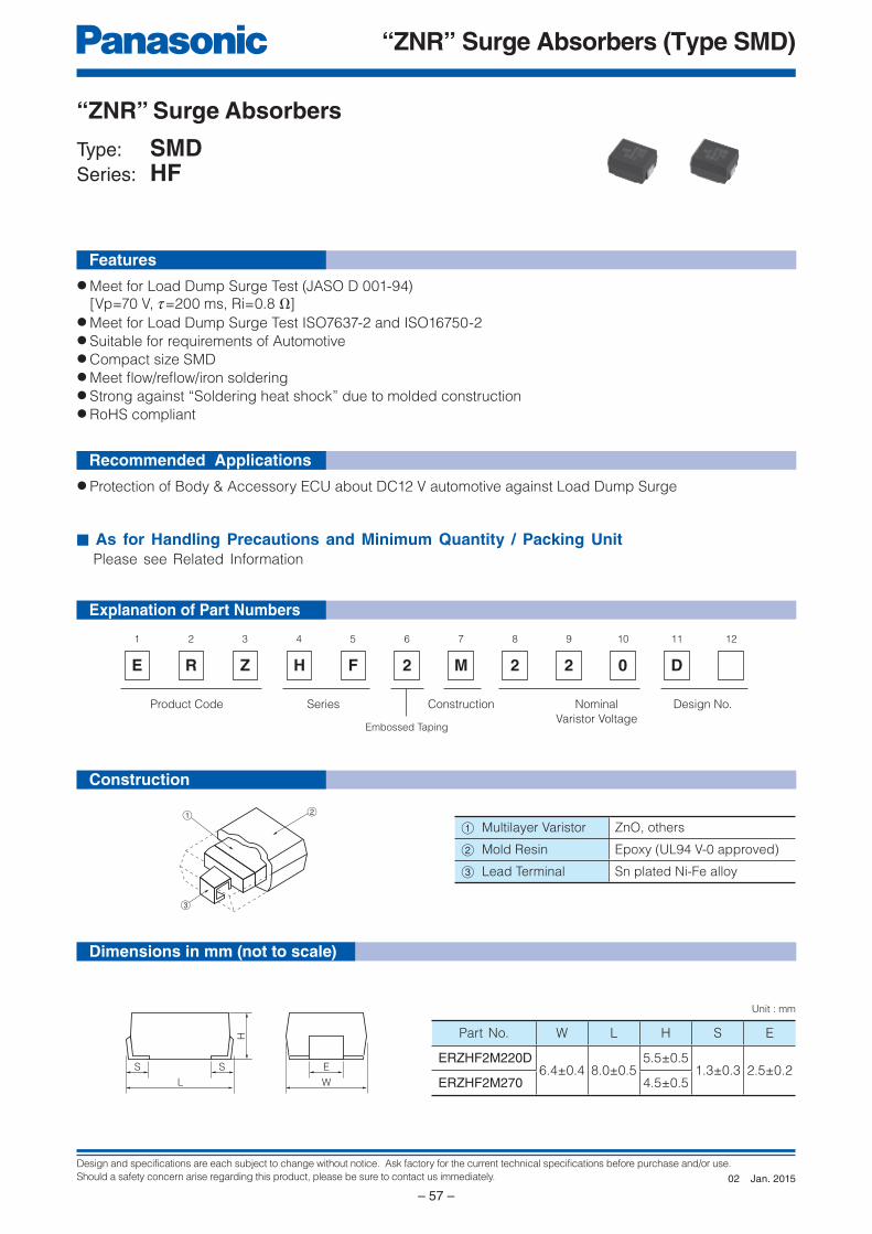
Design and specifications are each subject to change without notice. Ask factory for the current technical specifications before purchase and/or use.
Should a safety concern arise regarding this product, please be sure to contact us immediately.
“ZNR” Surge Absorbers (Type SMD)
– 57 –
E
1
R
2
Z H
3 4 5 6 7 8 9 10 11 12
F 2 M 2 2 0 D
Product Code Series Construction Nominal
Varistor Voltage
Design No.
Embossed Taping
1 2
3
E
W
SS
L
H
Explanation of Part Numbers
Construction
Features
Recommended Applications
● Meet for Load Dump Surge Test (JASO D 001-94)
[Vp=70 V, t=200 ms, Ri=0.8 Ω]● Meet for Load Dump Surge Test ISO7637-2 and ISO16750-2● Suitable for requirements of Automotive● Compact size SMD● Meet fl ow/refl ow/iron soldering● Strong against “Soldering heat shock” due to molded construction● RoHS compliant
● Protection of Body & Accessory ECU about DC12 V automotive against Load Dump Surge
“ZNR” Surge Absorbers
Type: SMDSeries: HF
■ As for Handling Precautions and Minimum Quantity / Packing Unit Please see Related Information
1 Multilayer Varistor ZnO, others
2 Mold Resin Epoxy (UL94 V-0 approved)
3 Lead Terminal Sn plated Ni-Fe alloy
Dimensions in mm (not to scale)
Part No. W L H S E
ERZHF2M220D6.4±0.4 8.0±0.5
5.5±0.51.3±0.3 2.5±0.2
ERZHF2M270 4.5±0.5
Unit : mm
Jan. 201502
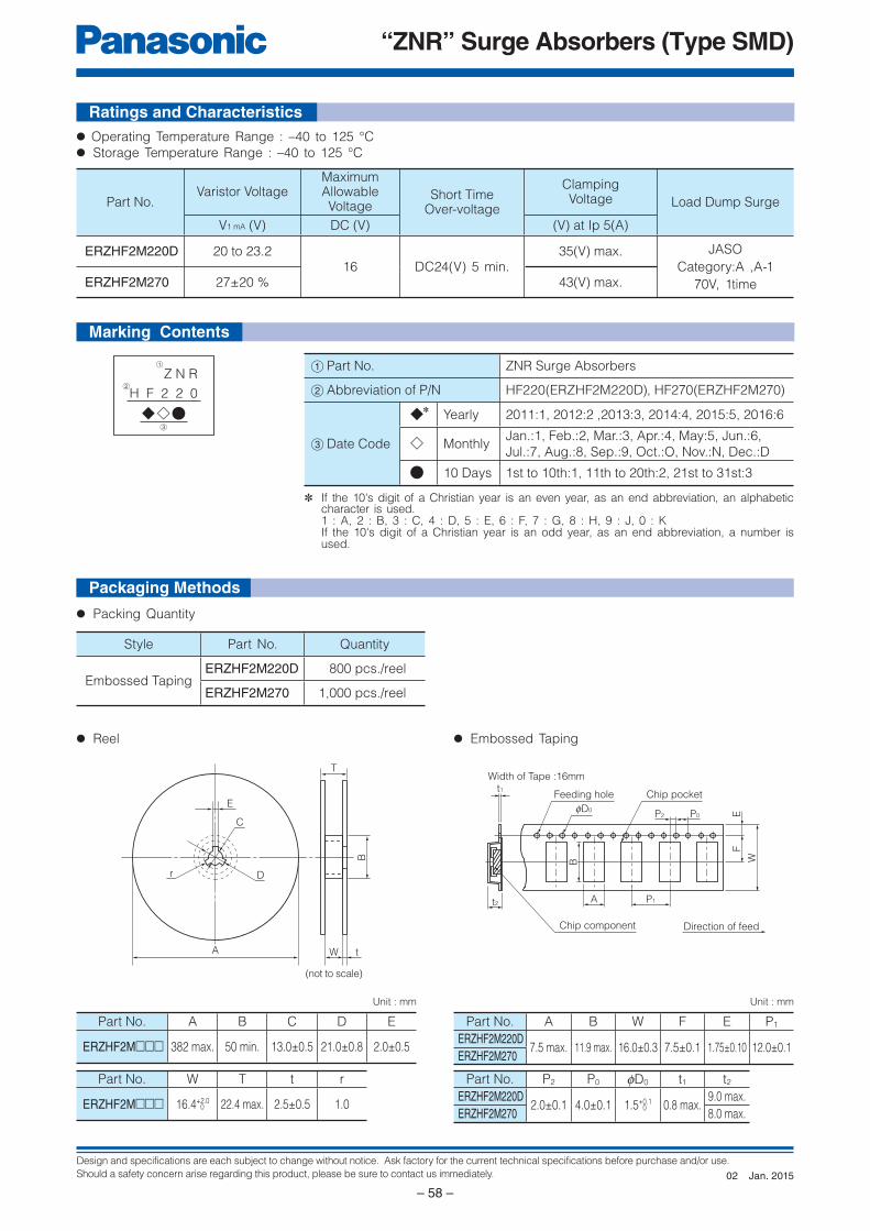
Design and specifications are each subject to change without notice. Ask factory for the current technical specifications before purchase and/or use.
Should a safety concern arise regarding this product, please be sure to contact us immediately.
“ZNR” Surge Absorbers (Type SMD)
– 58 –
T
C
E
Dr
B
W tA
(not to scale)
Z N R
H F 2 2 0
1
2
3
◆◇●
Width of Tape :16mm
fD0
A P1t2
EF
W
t1
B
Chip component Direction of feed
Chip pocketFeeding hole
P2 P0
● Operating Temperature Range : –40 to 125 °C● Storage Temperature Range : –40 to 125 °C
Part No.Varistor Voltage
MaximumAllowableVoltage
Short TimeOver-voltage
ClampingVoltage Load Dump Surge
V1 mA (V) DC (V) (V) at Ip 5(A)
ERZHF2M220D 20 to 23.216 DC24(V) 5 min.
35(V) max. JASO
Category:A ,A-1
70V, 1timeERZHF2M270 27±20 % 43(V) max.
● Packing Quantity
● Reel ● Embossed Taping
Part No. A B C D E
ERZHF2M□□□ 382 max. 50 min. 13.0±0.5 21.0±0.8 2.0±0.5
Part No. W T t r
ERZHF2M□□□ 16.4+2.0 22.4 max. 2.5±0.5 1.00
Part No. A B W F E P1
ERZHF2M220D7.5 max. 11.9 max. 16.0±0.3 7.5±0.1 1.75±0.10 12.0±0.1
ERZHF2M270
Part No. P2 P0 fD0 t1 t2
ERZHF2M220D2.0±0.1 4.0±0.1 1.5+0.1 0.8 max.
9.0 max.
ERZHF2M270 8.0 max.0
Style Part No. Quantity
Embossed TapingERZHF2M220D 800 pcs./reel
ERZHF2M270 1,000 pcs./reel
1 Part No. ZNR Surge Absorbers
2 Abbreviation of P/N HF220(ERZHF2M220D), HF270(ERZHF2M270)
3 Date Code
◆✽Yearly 2011:1, 2012:2 ,2013:3, 2014:4, 2015:5, 2016:6
◇ MonthlyJan.:1, Feb.:2, Mar.:3, Apr.:4, May:5, Jun.:6,
Jul.:7, Aug.:8, Sep.:9, Oct.:O, Nov.:N, Dec.:D
● 10 Days 1st to 10th:1, 11th to 20th:2, 21st to 31st:3
✽ If the 10's digit of a Christian year is an even year, as an end abbreviation, an alphabetic character is used.
1 : A, 2 : B, 3 : C, 4 : D, 5 : E, 6 : F, 7 : G, 8 : H, 9 : J, 0 : K If the 10's digit of a Christian year is an odd year, as an end abbreviation, a number is
used.
Ratings and Characteristics
Marking Contents
Packaging Methods
Unit : mm Unit : mm
Jan. 201502

Design and specifications are each subject to change without notice. Ask factory for the current technical specifications before purchase and/or use.
Should a safety concern arise regarding this product, please be sure to contact us immediately.
“ZNR” Surge Absorbers (Type SMD)
– 59 –
0 V
Vp=70 V
36.8 %
t=200 ms
PS Voltage
5.0
10.0
8.0
6.4
3.0
Land
Occupied Space
Product
Characteristics Test Methods Specifi cations
Standard Test Condition
Environmental conditions under which every measuring is done without doubt on the measuring results. Unless specially, specified, temperature, relative humidity are 5 °C to 35 °C, 45 to 85% RH respectively.
———
Maximum AllowableVoltage
The maximum DC voltage that can be applied continuously in the specifi ed environmental temperature range.
To meet thespecifi ed value.
Short Time Over-VoltageThe maximum DC Voltage that can be applied specified period without breakdown
Varistor Voltage
Voltage between both terminals of ZNR measured when 1 mA of DC current is applied under standard conditions. It is called V1. Measuring the varistor voltage should be made promptly to avoid heat affection.
Clamping VoltageThe maximum voltage between two terminals with the specified impulse current (8/20 μs).
Load Dump Surge
The test waveform of transient voltage which specified JASO Category A A-1 70 V without breakdown.
No breakdown
✽ Please Check Specification of the products about Mechanical & Environmental etc. requirements
Unit : mm
Performance Characteristics
Recommendation Land Size
Jan. 201502

Design and specifications are each subject to change without notice. Ask factory for the current technical specifications before purchase and/or use.
Should a safety concern arise regarding this product, please be sure to contact us immediately.
“ZNR” Surge Absorbers (Type SMD)
– 60 –
E
1
R
2
Z V
3 4 5 6 7 8 9 10 11 12
F M
1
2
Product Code Series Construction Nominal
Varistor Voltage
Design No.
Packaging Style
Bulk
Taping
4
1
5
2
3
E
W
SS
L
H
Explanation of Part Numbers
Construction
Features
Recommended Applications
Applicable Standards
● Large withstanding surge current capability, in compact size● Designed for fl ow/refl ow solderings● Low clamping voltage● RoHS compliant
● Protection of communication modules (Modem, xDSL, Terminal Adopter)● Protection of consumer, industrial equipment● Absorption of switching surge from relays
● PCQC (GB/T10193, GB/T10194) Registered in "Panasonic Part No."
“ZNR” Surge Absorbers
Type: SMDSeries: VF
■ As for Handling Precautions and Minimum Quantity / Packing Unit
Please see Related Information
Dimensions in mm (not to scale)
Unit : mm
Part No. W L H S E
ERZVF□M□□□ 6.0±0.4 8.0±0.5 3.2±0.3 1.3±0.3 2.5±0.2
1 ZNR element ZnO etc.
2 Resin mold Epoxy Resin(UL94V-0 approved)
3 Conductive
adhesiveSilver
4 Electrode Silver
5 Lead terminals Sn plated Ni-Fe Alloy
Jan. 201503
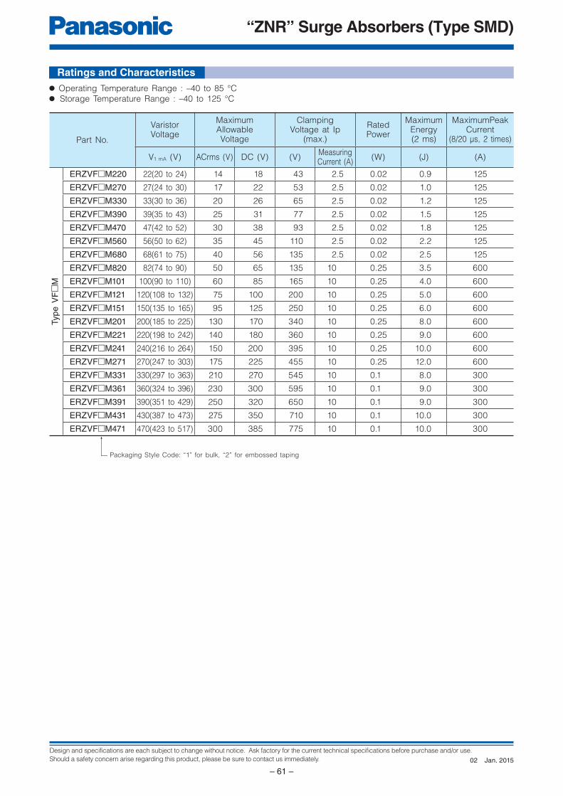
Design and specifications are each subject to change without notice. Ask factory for the current technical specifications before purchase and/or use.
Should a safety concern arise regarding this product, please be sure to contact us immediately.
“ZNR” Surge Absorbers (Type SMD)
– 61 –
Packaging Style Code: “1” for bulk, “2” for embossed taping
Part No.
VaristorVoltage
MaximumAllowableVoltage
ClampingVoltage at Ip
(max.)
RatedPower
MaximumEnergy(2 ms)
MaximumPeakCurrent
(8/20 μs, 2 times)
V1 mA (V) ACrms (V) DC (V) (V)MeasuringCurrent (A)
(W) (J) (A)
Typ
e V
F□
M
ERZVF□M220 22(20 to 24) 14 18 43 2.5 0.02 0.9 125
ERZVF□M270 27(24 to 30) 17 22 53 2.5 0.02 1.0 125
ERZVF□M330 33(30 to 36) 20 26 65 2.5 0.02 1.2 125
ERZVF□M390 39(35 to 43) 25 31 77 2.5 0.02 1.5 125
ERZVF□M470 47(42 to 52) 30 38 93 2.5 0.02 1.8 125
ERZVF□M560 56(50 to 62) 35 45 110 2.5 0.02 2.2 125
ERZVF□M680 68(61 to 75) 40 56 135 2.5 0.02 2.5 125
ERZVF□M820 82(74 to 90) 50 65 135 10 0.25 3.5 600
ERZVF□M101 100(90 to 110) 60 85 165 10 0.25 4.0 600
ERZVF□M121 120(108 to 132) 75 100 200 10 0.25 5.0 600
ERZVF□M151 150(135 to 165) 95 125 250 10 0.25 6.0 600
ERZVF□M201 200(185 to 225) 130 170 340 10 0.25 8.0 600
ERZVF□M221 220(198 to 242) 140 180 360 10 0.25 9.0 600
ERZVF□M241 240(216 to 264) 150 200 395 10 0.25 10.0 600
ERZVF□M271 270(247 to 303) 175 225 455 10 0.25 12.0 600
ERZVF□M331 330(297 to 363) 210 270 545 10 0.1 8.0 300
ERZVF□M361 360(324 to 396) 230 300 595 10 0.1 9.0 300
ERZVF□M391 390(351 to 429) 250 320 650 10 0.1 9.0 300
ERZVF□M431 430(387 to 473) 275 350 710 10 0.1 10.0 300
ERZVF□M471 470(423 to 517) 300 385 775 10 0.1 10.0 300
● Operating Temperature Range : –40 to 85 °C● Storage Temperature Range : –40 to 125 °C
Ratings and Characteristics
Jan. 201502
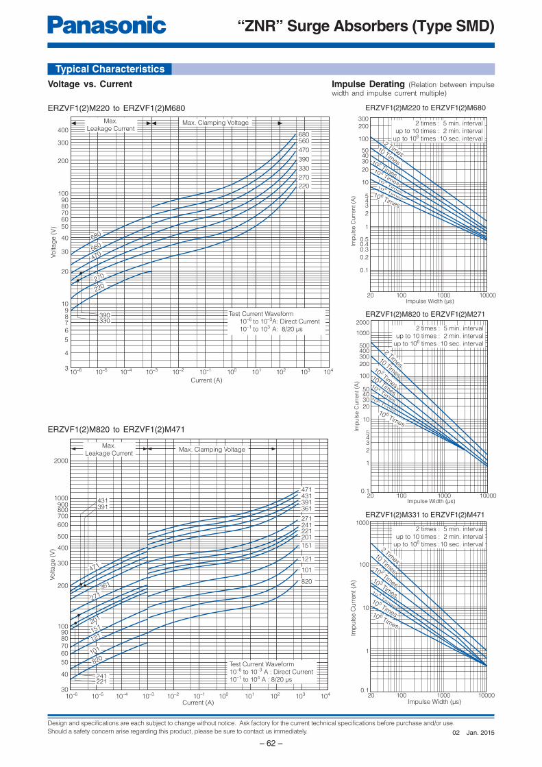
Design and specifications are each subject to change without notice. Ask factory for the current technical specifications before purchase and/or use.
Should a safety concern arise regarding this product, please be sure to contact us immediately.
“ZNR” Surge Absorbers (Type SMD)
– 62 –
Impulse Width (μs)
Imp
uls
e C
urr
ent (A
)
20 100 1000 10000
0.1
0.2
0.30.40.5
1
2
345
10
20
304050
100
200
300
2 Times10 Tim
es10 2 Times
10 3 Tim
es10 4
Tim
es
10 6 Times
10 5
Tim
es
5 min. interval
2 min. interval
10 sec. interval
2 times :
up to 10 times :
up to 106 times :
1000
100
10
1
20 100 10000.1
10000
2 Times
10 Times10 2
Times
10 3 Times
10 4
Tim
es
10 6 Times
10 5 Times
Impulse Width (μs)
Imp
uls
e C
urr
ent (A
)
5 min. interval
2 min. interval
10 sec. interval
2 times :
up to 10 times :
up to 106 times :
2000
1000900800700
600
500
400
300
200
10090807060
50
40
3010–6 10–5 10–4 10–3 10–2 10–1 100 101 102 103 104
271
471431391361
241221201
820
101
121
151
820101
121151201
271
361
471
Current (A)
Voltag
e (
V)
Test Current Waveform
10–6 to 10–3 A : Direct Current
10–1 to 104 A : 8/20 μs
Max. Clamping VoltageMax.
Leakage Current
431
241221
391
400
300
200
1009080706050
40
30
76
3
20
1098
10–6 10–5 10–4 10–3 10–2 10–1 100 101 102 103 104
680
560
470
270
220
4
5
Current (A)
Vo
lta
ge
(V
)
Test Current Waveform
10–6 to 10–3A: Direct Current
10–1 to 103 A: 8/20 μs
Max. Clamping VoltageMax.
Leakage Current
390330
680560
470
390
330
270
220
ERZVF1(2)M220 to ERZVF1(2)M680
ERZVF1(2)M820 to ERZVF1(2)M271
ERZVF1(2)M331 to ERZVF1(2)M471
ERZVF1(2)M820 to ERZVF1(2)M471
ERZVF1(2)M220 to ERZVF1(2)M680
Typical Characteristics
Voltage vs. Current Impulse Derating (Relation between impulse width and impulse current multiple)
Impulse Width (μs)
Imp
uls
e C
urr
ent (A
)
20 100 1000 10000
1
0.1
2
345
10
20304050
100
200
300400500
1000
2000
2 Times
10 Times
10 2 Tim
es10 3 Tim
es10 4
Times
10 6 Times
105
Tim
es
5 min. interval
2 min. interval
10 sec. interval
2 times :
up to 10 times :
up to 106 times :
Jan. 201502

Design and specifications are each subject to change without notice. Ask factory for the current technical specifications before purchase and/or use.
Should a safety concern arise regarding this product, please be sure to contact us immediately.
“ZNR” Surge Absorbers (Type SMD)
– 63 –
Z N R
V F M
01
1
2 3
4
T
C
E
Dr
B
W tA
(not to scale)
(W=16 mm)
t1
t2
Chip component
P1
P2 P0
Chip pocketFeeding hole
Tape running
direction
EF
WBf D0
(not to scale)
A
● Packing Quantity
Marking Contents
Packaging Methods
1 Product Name ZNR, ZNR Surge Absorbers
2 Series VF□M, VF Series
3 Abbreviation of
Part No.
The fi rst two digits are signifi cant fi gures and the third one
denotes the number of zeros following.
4 Date CodeLeft
✽ (Year) 2011:1, 2012:2, 2013:3, 2014:4, 2015:5, 2016:6
Right(Month) Jan. to Sep.:1 to 9, Oct.:O, Nov.:N, Dec.:D
● Reel ● Embossed Taping
Style Quantity
Embossed taping 2,000 pcs./reel
Bulk 200 pcs./bag
✽ If the 10's digit of a Christian year is an even year, as an end abbreviation, an alphabetic character is used.
1 : A, 2 : B, 3 : C, 4 : D, 5 : E, 6 : F, 7 : G, 8 : H, 9 : J, 0 : K If the 10's digit of a Christian year is an odd year, as an end abbreviation, a number
is used.
Part No. A B C D E
ERZVF□M□□□ 382 max. 50 min. 13.0±0.5 21.0±0.8 2.0±0.5
Part No. W T t r
ERZVF□M□□□ 16.4+2.0 22.4 max. 2.5±0.5 1.00
Part No. A B W F E P1
ERZVF□M□□□ 6.8±0.2 11.9 max. 16.0±0.3 7.5±0.10 1.75±0.10 8.0±0.1
Part No. P2 P0 fD0 t1 t2
ERZVF□M□□□ 2.0±0.1 4.0±0.1 1.5+0.1 0.6 max. 6.5 max.0
Jan. 201502

Design and specifications are each subject to change without notice. Ask factory for the current technical specifications before purchase and/or use.
Should a safety concern arise regarding this product, please be sure to contact us immediately.
“ZNR” Surge Absorbers (Type SMD)
– 64 –
5.0
10.0
8.0
6.0
3.0
Occupied Space
Product
Land
Unit : mm
Performance Characteristics
Recommendation Land Size
Characteristics Test Methods Specifi cations
Standard TestCondition
Electrical measurements (initial/after tests) shall be conducted at temperature of 5 to 35 °C, relative humidity of maximum 85 %
———
Varistor VoltageThe voltage between two terminals with the specifi ed measuring current 1mA DC applied is called V1 or V1mA. The measurement should be made as fast as possible to avoid heat effects.
To meet the
specifi ed value.
Maximum AllowableVoltage
The recommended maximum sinusoidal wave voltage (rms) or the maximum DC voltage that can be applied continuously.
Clamping VoltageThe maximum voltage between two terminals with the specifi edimpulse current (8/20 μs).
Rated PowerThe maximum power that can be applied within the specifiedambient temperature.
Maximum EnergyMaximum energy of less than ±10 % of the varistor voltage change when the standard impulse (2 ms) is applied one time.
MaximumPeak Current
Maximum current of less than ±10 % of the varistor voltage change when impulse current (8/20 μs) is applied twice continuously with an interval of 5 minutes.
Temperature Co ef fi cient of Varistor Volt age
V1mA at 85 °C – V1mA at 25 °C×
1× 100(%/°C)
V1mA at 25 °C 600 to –0.05 %/°C
Impulse Life (I)
The change of Vc shall be measured after the specifi ed impulse is applied 10000 times continuously with an interval of 10 seconds at room temperature.
Part No. Waveform Current
ERZVF□M220 to ERZVF□M680
ERZVF□M820 to ERZVF□M271
ERZVF□M331 to ERZVF□M471
8/20 μs
8/20 μs
8/20 μs
18 A
50 A
30 A
ΔV1mA/V1mA < ±10 %
Impulse Life (II)
The change of Vc shall be measured after the specifi ed impulse is applied 100000 times continuously with an interval of 10 seconds at room temperature.
Part No. Waveform Current
ERZVF□M220 to ERZVF□M680
ERZVF□M820 to ERZVF□M271
ERZVF□M331 to ERZVF□M471
8/20 μs
8/20 μs
8/20 μs
12 A
35 A
20 A
ΔV1mA/V1mA < ±10 %
Jan. 201503

Design and specifications are each subject to change without notice. Ask factory for the current technical specifications before purchase and/or use.
Should a safety concern arise regarding this product, please be sure to contact us immediately.
“ZNR” Transient/Surge Absorbers
– 65 –
“ZNR” Transient/Surge Absorbers, Type D, Series V“ZNR” Transient/Surge Absorbers, Type SMD, Series HF, VF
Handling Precautions
In case that a ZNR Surge Absorber (hereafter referred to as the ZNR, or product name) is used, if an abnormality takes place because of peripheral conditions of the ZNR(material, environments, power source conditions, circuit conditions, etc. in equipment design), fire, electric shock, burn, or product failure may be occur. The precautions for this product are described below, understand the content thoroughly before usage. For more questions, contact us.
Safety Precautions
1. Precautions to be strictly observed
1.1 Confirmation of performance ratings
Use the ZNR within its rated range of performance such as the Max. allowable voltage, withstanding surge
current, withstanding energy, impulse life(surge life), average pulse power, and operating temperature range.
If used outside the range, the ZNR can be degrade and have element fracture, which may result in smoking
and ignition.
1.2 To avoid accidents due to unexpected phenomena, take the following measures
1) In the event of fracture of the ZNR, its pieces may scatter ; hence, put the case or cover of the set product in place.
2) Do not install the ZNR near combustible substances(polyvinyl chloride wires, resin moldings, etc.). If it is difficult to do,
install a nonflammable cover.
3) Across-the-line use
When the ZNR is used across a line, put a current fuse in series with the ZNR(Refer to Item 2.1.1). (4) and
Table 1.
4) Use between line to ground
(1) If the case that the ZNR is used between a line to the ground, the short-circuit of the ZNR may not blow the
current fuse because of grounding resistance, which may cause smoking and ignition of the ZNR’s exterior resin.
As the measure against it, install an earth leakage breaker on the power supply side of the ZNR position. If no
earth leakage breaker is installed, use a thermal fuse together wth a current fuse in series. (Refer to Table 1.)
(2) If the case that the ZNR is used between a live part to metal case, an electric shock may develop at a
shortcircuit of the ZNR ; hence, ground the metal case to the ground or keep it from the human body.
2. Application notes
2.1 Pay attention to the following items to avoid the shortened life and failure of the ZNR
1) Circuit conditions
(1) Select a ZNR of which the maximum voltage including fluctuations in source voltage allows for the
maximum permissible circuit voltage. (Refer to Table 1.)
(2) In cases that surges are intermittently applied at short intervals(for example, in case that the voltage of the
noise simulator test is implemented etc.), do not let them exceed the ZNR’s rated power.
(3) Select a ZNR recommended in Table 1.
<1> Across-the-line use
If possible, use a Part No. marked with ✽ in case of voltage temporarily rises load unbalance of
separately-wired loads, short between hot and neutral-line, open of neutral line in single-phase-three-wired
system, and due to resonance at switching for a capacitive, inductive load.
<2> Used between line to ground
Use a different Part No. from “Across-the-line use” as table 1, because of raising voltage in case of
“Line to Ground Fault”.
Use a Part No. marked with ✽✽ in table 1, in case of the insulation resistance test(500 VDC) for
equip ment. When using a Part of the varistor voltage that the insulation efficiency examination can not
be cleared, there is a case where the surge absorber can be done by removing it from the circuit
depending on the circuit condition(Refer examination of Japan Domestic Safety Regulations).
Use a Part No. marked with ✽✽✽ in table 1, in case of the withstanding voltage test(1000 VAC or 1200
VAC) for equipment.
Mar. 201504

Design and specifications are each subject to change without notice. Ask factory for the current technical specifications before purchase and/or use.
Should a safety concern arise regarding this product, please be sure to contact us immediately.
“ZNR” Transient/Surge Absorbers
– 66 –
Current Fuse
ZNR
Power Source SideProtected
Equipment
fuse ZNR1
Protected
Equipment
L
N
fuse ZNR1
ZNR2
Thermal FuseThermal
coupling
Protected
Equipment
{
L
N
fuse
ZNR3
ZNR3 ZNR3
Protected
Equipment
fuse
ZNR3
Thermal
coupling
Thermal Fuse
Protected
Equipment
{
ZNR3 {
ZNR4 {
(4) Concerning current fuse
<1> We recommend selecting a ZNR and the rated current of a current fuse as follows.
Finally, please be sure that there is no danger if the ZNR mounted on the equipment breaks.
<2> The recommended fuse position is shown in table 1, “Example of ZNR application”, however, if the load
current of protected equipment is larger than that of the above recommended fuse rated current, install
a current fuse at the position shown below.
✽ Fuses shall use rated voltages ap pro pri ate for circuits.✽ Concerning HF series, please confirm adjusted to load dump surge and protection cooperation.
● Type SMD, Series VF
✽ Fuses shall use rated voltages ap pro pri ate for circuits.
● Type D, Series V
Standard Part No. ERZV05D□□□ ERZV07D□□□ ERZV09D□□□ ERZV10D□□□ ERZV14D□□□ ERZV20D□□□
Fuse rated current 3 A max. 5 A max. 7 A max. 7 A max. 10 A max. 10 A max.
Standard Part No. ERZVF□M□□□
Fuse rated current 5 A max.
(5) Concerning thermal fuse
Set a thermal fuse to get high thermal conductivity with ZNR.
Table 1 Example of ZNR application
Connections e
xam
ple
Across-the-Line use Use between Line to ground
DC/AC
Single-phase
DC/AC
Single-phase
AC
3-phase
AC
3-phase
Exam
ple
of va
risto
r vo
ltage
ZNR Source
voltage
Nominai varistor voltage
Type D SMD Mold Type
ZNR1
ZNR3
AC100 V 201 to 361✽ 201 to 361✽
AC120 V 241 to 431✽ 241 to 431✽
AC200 V 471 to 621✽ 471
AC220 V 471 to 621✽ 471
AC240 V 511, 621✽ —
AC380 V 821 —
ZNRSource voltage
Nominai varistor voltage
Type D SMD Mold Type
ZNR2ZNR4
AC100 V
AC220 V
471
511
621✽
821 and more✽✽
182✽✽✽
471
—
—
—
—
AC230 V
AC240 V
511
621✽
821 and more✽✽
182✽✽✽
—
—
—
—
AC380 V112✽✽
182✽✽✽
—
—
Note : Element size is selected by impulse Condition.
Mar. 201504
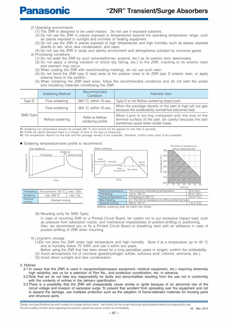
Design and specifications are each subject to change without notice. Ask factory for the current technical specifications before purchase and/or use.
Should a safety concern arise regarding this product, please be sure to contact us immediately.
“ZNR” Transient/Surge Absorbers
– 67 –
Soldering
Preheating Gradual cooling
Time
Tem
pe
ratu
re (
°C)
Flow soldering
0 10 20 30 40 50 60200
210
220
230
240
260
Tem
pe
ratu
re (
°C)
The limits of resistance to
reflow solderling heat
Time (s)
250
Reflow soldering
Tem
pe
ratu
re (
°C)
Rising
temperature(I) Preheating
Rising
temperature(II) Main heating
Gradual
cooling
Time
2) Operating environments(1) The ZNR is designed to be used indoors. Do not use it exposed outdoors.(2) Do not use the ZNR in places exposed to temperatures beyond the operating temperature range, such
as places exposed to sunlight and vicinities of heating equipment.(3) Do not use the ZNR in places exposed to high temperatures and high humidity, such as places exposed
directly to rain, wind, dew condensation, and vapor.(4) Do not use the ZNR in dusty and salinity environment and atmospheres polluted by corrosive gases.
3) Processing conditions(1) Do not wash the ZNR by such solvents(thinner, acetone, etc.) as its exterior resin deteriorates.(2) Do not apply a strong vibration or shock (by falling, etc.) to the ZNR, cracking to its exterior resin
and element may occur.(3) When coating the ZNR with resin(including molding), do not use such resin.(4) Do not bend the ZNR type D lead wires at the position close to its ZNR type D exterior resin, or apply
external force to the position.(5) When soldering the ZNR lead wires, follow the recommended conditions and do not melt the solder
and insulating materials constituting the ZNR.
✽1 Soldering iron temperature should not exceed 400 °C and should not be applied for mor than 5 seconds.✽2 Profile be careful because there is a margin of error in the way of measuring.✽3 The temperature depend on the size and the package density of the substrate. Therefore, confirm every kind of the substrate.
Soldering MethodRecommended
ConditionAttention Item
Type D Flow soldering 260 °C, within 10 sec. Type D is not Refl ow soldering object part.
SMD Type
Flow soldering 260 °C, within 10 sec.When the package density of the part is high pill out gas because the solderability sometimes becomes bad.
Refl ow sol der ingRefer to Refl owsoldering profi le
When Land is too big compared with the size of the terminal surface of the part, be careful because the part sometimes upset when solder fuses.
● Soldering temperature-time profile to recommend
(Reflow soldering shall be within two times)
Rising temperature I The normal to preheating temperature 30 to 60 sPreheating 150 to 180 °C 60 to 120 sRising temperature II Preheating to 200 °C 2 to 6 °C/sMain heating (cf. The limit of resistance to refl ow soldering heat)Gradual cooling 200 to 100 °C 1 to 4 °C/s
(6) Mounting (only for SMD Type)
In case of mounting ZNR on a Printed Circuit Board, be careful not to put excessive impact load, such as pressure from adsorption nozzle, and mechanical impact/stress of position-shifting or positioning.Also, we recommend you to fix a Printed Circuit Board to sheathing resin with an adhesive in case of position-shifting of ZNR when mounting.
4) Long-term storage(1)Do not store the ZNR under high temperature and high humidity. Store it at a temperature up to 40 °C
and at humidity below 75 %RH, and use it within two years. Before using the ZNR that has been stored for a long period(two years or longer), confirm the solderability.(2) Avoid atmospheres full of corrosive gases(hydrogen sulfide, sulfurous acid, chlorine, ammonia, etc.).(3) Avoid direct sunlight and dew condensation.
3. Notices3.1 In cases that the ZNR is used in equipment(aerospace equipment, medical equipment, etc.) re quir ing extremely
high reliability, ask us for a selection of Part No., and protection coordination, etc. in advance.3.2 Note that we do not take any responsibility for faults and abnormalities resulting from the use not in conformity
with the contents of entries in the delivery specification.3.3 There is a possibility that the ZNR will unexpectedly cause smoke or ignite because of an abnormal rise of the
circuit voltage and invasion of excessive surge. To prevent that accident from spreading over the equipment and not to expand the damage, use multiplex protection such as the adoption of frame-retardant materials for hous ing parts and structural parts.
Preheating The normal to 130 °C max. 120s
Soldering max. 260 °C max. 10s
Gradualcooling
Gradual cooling
Mar. 201504

Design and specifications are each subject to change without notice. Ask factory for the current technical specifications before purchase and/or use.
Should a safety concern arise regarding this product, please be sure to contact us immediately.
“ZNR” Transient/Surge Absorbers (Type SC)
– 68 –
E
1
R
2
Z
3 4 5 6 7 8 9 10 11 12
Element Size Design No.NominalVaristor Voltage
Type
V 4 C
Product Code Series
S 3
Shape
Part Number
DT
18
25
7
2-f3.4
7
8H
Date code
ZNR
Explanation of Part Numbers
Features
Recommended Applications
● Very large surge withstanding capability with a compact size● Fast response to steep impulse voltage● Low clamping voltage for better surge protection● No follow-on current● RoHS compliant
● Power suppliers for OA, FA, telecommunication or industrial equipment● Traffi c or railroad systems● Surge protection of automatic control devices for power distribution line
“ZNR” Transient/Surge Absorbers
Type : SC
The ZNR Type SC protects power supply facilities, communications equipment from steep lightning surges, and it is a suitable product to incorporate it in a serge protective device corresponding to the Japanese Industrial Standards (JIS C 5381-1).
Part No. D max. H max. T max.
ERZVS34C201
36 47
9.0
ERZVS34C241 9.2
ERZVS34C271 9.5
ERZVS34C361 10.4
ERZVS34C431 11.1
ERZVS34C471 11.3
ERZVS34C511 9.7
ERZVS34C621 9.7
ERZVS34C751 10.5
ERZVS34C821 11.0
ERZVS34C951 11.5
(Unit : mm)
■ As for Handling Precautions and Minimum Quantity / Packing Unit
Please see Related Information
Dimensions in mm (not to scale)
Jan. 201502
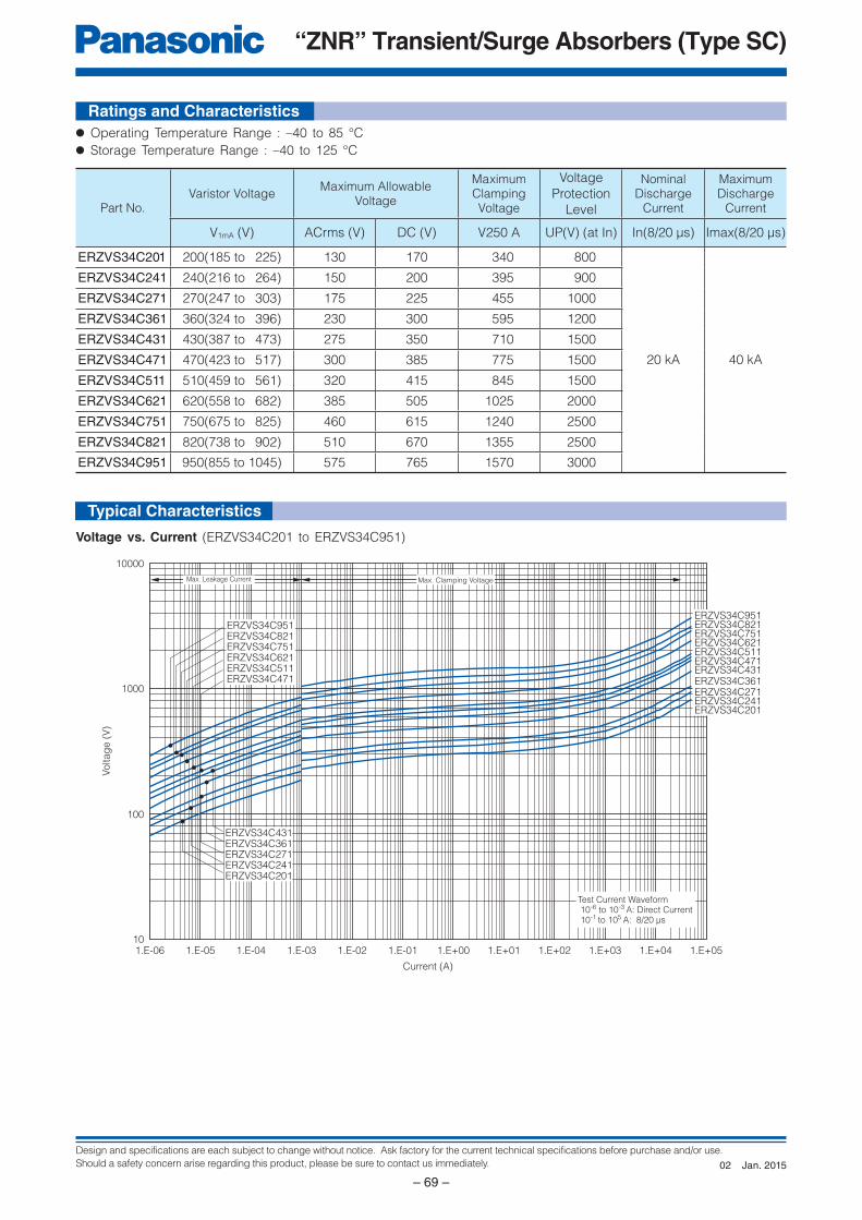
Design and specifications are each subject to change without notice. Ask factory for the current technical specifications before purchase and/or use.
Should a safety concern arise regarding this product, please be sure to contact us immediately.
“ZNR” Transient/Surge Absorbers (Type SC)
– 69 –
1.E-05 1.E-02 1.E-01 1.E+00 1.E+01 1.E+03 1.E+05
ERZVS34C951ERZVS34C821ERZVS34C751ERZVS34C621ERZVS34C511ERZVS34C471ERZVS34C431ERZVS34C361ERZVS34C271ERZVS34C241ERZVS34C201
Voltag
e (
V)
Current (A)
Test Current Waveform 10-6 to 10-3 A: Direct Current 10-1 to 105 A: 8/20 μs
10000
1000
100
101.E-06 1.E-04 1.E-03 1.E+02 1.E+04
Max. Clamping VoltageMax. Leakage Current
ERZVS34C431ERZVS34C361ERZVS34C271ERZVS34C241ERZVS34C201
ERZVS34C951ERZVS34C821ERZVS34C751ERZVS34C621ERZVS34C511ERZVS34C471
Ratings and Characteristics
Voltage vs. Current (ERZVS34C201 to ERZVS34C951)
Part No.Varistor Voltage
Maximum AllowableVoltage
MaximumClampingVoltage
Voltage
Protection
Level
NominalDischarge
Current
MaximumDischarge
Current
V1mA (V) ACrms (V) DC (V) V250 A UP(V) (at In) In(8/20 μs) Imax(8/20 μs)
ERZVS34C201 200(185 to 225) 130 170 340 800
20 kA 40 kA
ERZVS34C241 240(216 to 264) 150 200 395 900
ERZVS34C271 270(247 to 303) 175 225 455 1000
ERZVS34C361 360(324 to 396) 230 300 595 1200
ERZVS34C431 430(387 to 473) 275 350 710 1500
ERZVS34C471 470(423 to 517) 300 385 775 1500
ERZVS34C511 510(459 to 561) 320 415 845 1500
ERZVS34C621 620(558 to 682) 385 505 1025 2000
ERZVS34C751 750(675 to 825) 460 615 1240 2500
ERZVS34C821 820(738 to 902) 510 670 1355 2500
ERZVS34C951 950(855 to 1045) 575 765 1570 3000
● Operating Temperature Range : –40 to 85 °C
● Storage Temperature Range : –40 to 125 °C
Typical Characteristics
Jan. 201502

Design and specifications are each subject to change without notice. Ask factory for the current technical specifications before purchase and/or use.
Should a safety concern arise regarding this product, please be sure to contact us immediately.
“ZNR” Transient/Surge Absorbers (Type E)
– 70 –
24 ISOM4
L
W
12
H
ZNR
5
4.3
14
Part No.
Date code
E
1
R
2
Z
3 4 5 6 7 8 9 10 11 12
Product Code Element Size Type Design No.NominalVaristor Voltage
Tolerance
C E K
General
UL/CSA Recognized
–
Y
Explanation of Part Numbers
Features
Recommended Applications
● UL and CSA recognized components● Very large surge withstanding capability with a compact size● Direct mounting on boards like a power distribution board available● Fast response to steep impulse voltage● Low clamping voltage for better surge protection● RoHS compliant
● Transistor, diode, IC, thyristor or triac semiconductor protection● Surge protection in industrial power plant operations● Relay or electromagnetic valve surge absorption● Surge absorption applications in broadcasting, communications devices, traffi c/railroad, agricultural facilities, waterworks● Surge protection of automatic control devices for power distribution line
Note : Ask our factory for Product Specifi cation before use.
“ZNR” Transient/Surge Absorbers
Type : E
The ZNR Type E is capable of handling larger surgeenergy than Type D in applications to protect electronic equipment or semiconductor devices from switching and induced lightning surges.
(Unit : mm)
■ As for Handling Precautions and Minimum Quantity / Packing Unit
Please see Related Information
Dimensions in mm (not to scale)
Part No. W H L
ERZC20EK□□□(Y) 48±1 42±1 39±1
ERZC32EK□□□(Y) 60±1 55±1 51±1
Related Standards
● Each type designation is not registered by Part Num ber.
Standard No. UL1449 CSA C22.2 No.1 Class 2221 01
Title Surge Protective DevicesAccessories and Parts for Electronic Products (Varistor for Across-The-Line use as transient protection on 120V ac nominal system)
File No. E321499 LR-92226
Mar. 201703
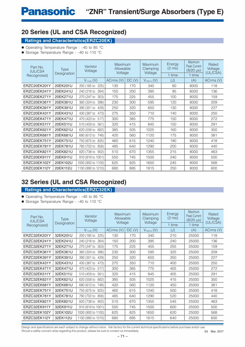
Design and specifications are each subject to change without notice. Ask factory for the current technical specifications before purchase and/or use.
Should a safety concern arise regarding this product, please be sure to contact us immediately.
“ZNR” Transient/Surge Absorbers (Type E)
– 71 –
● Operating Temperature Range : –40 to 85 °C
● Storage Temperature Range : –40 to 110 °C
● Operating Temperature Range : –40 to 85 °C
● Storage Temperature Range : –40 to 110 °C
20 Series (UL and CSA Recognized)
32 Series (UL and CSA Recognized)
Ratings and Characteristics(ERZC20EK)
Ratings and Characteristics(ERZC32EK)
Part No.(UL/CSA
Recognized)
TypeDesignation
VaristorVoltage
MaximumAllowableVoltage
MaximumClampingVoltage
Energy(2 ms)
MaximumPeak Current(8/20 μs)
RatedVoltage
(UL/CSA)1 time 1 time
V1 mA (V) ACrms (V) DC (V) V100 A (V) (J) (A) ACrms (V)
ERZC20EK201Y 20EK201U 200 (185 to 225) 130 170 340 80 8000 118
ERZC20EK241Y 20EK241U 240 (216 to 264) 150 200 395 95 8000 136
ERZC20EK271Y 20EK271U 270 (247 to 303) 175 225 455 100 8000 159
ERZC20EK361Y 20EK361U 360 (324 to 396) 230 300 595 120 8000 209
ERZC20EK391Y 20EK391U 390 (351 to 429) 250 320 650 130 8000 227
ERZC20EK431Y 20EK431U 430 (387 to 473) 275 350 710 140 8000 250
ERZC20EK471Y 20EK471U 470 (423 to 517) 300 385 775 150 8000 272
ERZC20EK511Y 20EK511U 510 (459 to 561) 320 415 845 150 8000 291
ERZC20EK621Y 20EK621U 620 (558 to 682) 385 505 1025 160 8000 350
ERZC20EK681Y 20EK681U 680 (612 to 748) 420 560 1120 175 8000 381
ERZC20EK751Y 20EK751U 750 (675 to 825) 460 615 1240 190 8000 418
ERZC20EK781Y 20EK781U 780 (702 to 858) 485 640 1290 200 8000 440
ERZC20EK821Y 20EK821U 820 (738 to 902) 510 670 1355 215 8000 463
ERZC20EK911Y 20EK911U 910 (819 to 1001) 550 745 1500 240 8000 500
ERZC20EK102Y 20EK102U 1000 (900 to 1100) 625 825 1650 245 8000 568
ERZC20EK112Y 20EK112U 1100 (990 to 1210) 680 895 1815 250 8000 600
Part No.(UL/CSA
Recognized)
TypeDesignation
VaristorVoltage
MaximumAllowableVoltage
MaximumClampingVoltage
Energy(2 ms)
MaximumPeak Current(8/20 μs)
RatedVoltage
(UL/CSA)1 time 1 time
V1 mA (V) ACrms (V) DC (V) V100 A (V) (J) (A) ACrms (V)
ERZC32EK201Y 32EK201U 200 (185 to 225) 130 170 340 210 25000 118
ERZC32EK241Y 32EK241U 240 (216 to 264) 150 200 395 240 25000 136
ERZC32EK271Y 32EK271U 270 (247 to 303) 175 225 455 255 25000 159
ERZC32EK361Y 32EK361U 360 (324 to 396) 230 300 595 325 25000 209
ERZC32EK391Y 32EK391U 390 (351 to 429) 250 320 650 350 25000 227
ERZC32EK431Y 32EK431U 430 (387 to 473) 275 350 710 400 25000 250
ERZC32EK471Y 32EK471U 470 (423 to 517) 300 385 775 405 25000 272
ERZC32EK511Y 32EK511U 510 (459 to 561) 320 415 845 405 25000 291
ERZC32EK621Y 32EK621U 620 (558 to 682) 385 505 1025 415 25000 350
ERZC32EK681Y 32EK681U 680 (612 to 748) 420 560 1120 450 25000 381
ERZC32EK751Y 32EK751U 750 (675 to 825) 460 615 1240 500 25000 418
ERZC32EK781Y 32EK781U 780 (702 to 858) 485 640 1290 520 25000 440
ERZC32EK821Y 32EK821U 820 (738 to 902) 510 670 1355 545 25000 463
ERZC32EK911Y 32EK911U 910 (819 to 1001) 550 745 1500 600 25000 500
ERZC32EK102Y 32EK102U 1000 (900 to 1100) 625 825 1650 620 25000 568
ERZC32EK112Y 32EK112U 1100 (990 to 1210) 680 895 1815 640 25000 600
Mar. 201703

Design and specifications are each subject to change without notice. Ask factory for the current technical specifications before purchase and/or use.
Should a safety concern arise regarding this product, please be sure to contact us immediately.
“ZNR” Transient/Surge Absorbers (Type E)
– 72 –
● Operating Temperature Range : –40 to 85 °C
● Storage Temperature Range : –40 to 110 °C
● Operating Temperature Range : –40 to 85 °C
● Storage Temperature Range : –40 to 110 °C
Part No.
VaristorVoltage
MaximumAllowableVoltage
MaximumClampingVoltage
RatedPower
Energy(2 ms)
MaximumPeak Current
(8/20 μs)
TypicalCapacitance
(Reference)1 time 2 times
V1 mA (V) ACrms (V) DC (V) V100 A (V) (W) (J) (A) (A) at 1kHz (pF)
ERZC20EK201 200 (185 to 225) 130 170 340 0.8 80 8000 5000 2300
ERZC20EK241 240 (216 to 264) 150 200 395 0.8 95 8000 5000 1500
ERZC20EK271 270 (247 to 303) 175 225 455 0.8 100 8000 5000 1400
ERZC20EK361 360 (324 to 396) 230 300 595 0.8 120 8000 5000 1300
ERZC20EK391 390 (351 to 429) 250 320 650 0.8 130 8000 5000 1200
ERZC20EK431 430 (387 to 473) 275 350 710 0.8 140 8000 5000 1000
ERZC20EK471 470 (423 to 517) 300 385 775 0.8 150 8000 5000 950
ERZC20EK511 510 (459 to 561) 320 415 845 0.8 150 8000 5000 930
ERZC20EK621 620 (558 to 682) 385 505 1025 0.8 160 8000 5000 900
ERZC20EK681 680 (612 to 748) 420 560 1120 0.8 175 8000 5000 850
ERZC20EK751 750 (675 to 825) 460 615 1240 0.8 190 8000 5000 800
ERZC20EK781 780 (702 to 858) 485 640 1290 0.8 200 8000 5000 800
ERZC20EK821 820 (738 to 902) 510 670 1355 0.8 215 8000 5000 700
ERZC20EK911 910 (819 to 1001) 550 745 1500 0.8 240 8000 5000 700
ERZC20EK102 1000 (900 to 1100) 625 825 1650 0.8 245 8000 5000 400
ERZC20EK112 1100 (990 to 1210) 680 895 1815 0.8 250 8000 5000 350
Part No.
VaristorVoltage
MaximumAllowableVoltage
MaximumClampingVoltage
RatedPower
Energy(2 ms)
MaximumPeak Current
(8/20 μs)
TypicalCapacitance
(Reference)1 time 2 times
V1 mA (V) ACrms (V) DC (V) V200 A (V) (W) (J) (A) (A) at 1kHz (pF)
ERZC32EK201 200 (185 to 225) 130 170 340 1.2 210 25000 20000 5500
ERZC32EK241 240 (216 to 264) 150 200 395 1.2 240 25000 20000 5000
ERZC32EK271 270 (247 to 303) 175 225 455 1.2 255 25000 20000 4200
ERZC32EK361 360 (324 to 396) 230 300 595 1.2 325 25000 20000 3500
ERZC32EK391 390 (351 to 429) 250 320 650 1.2 350 25000 20000 3000
ERZC32EK431 430 (387 to 473) 275 350 710 1.2 400 25000 20000 2500
ERZC32EK471 470 (423 to 517) 300 385 775 1.2 405 25000 20000 2500
ERZC32EK511 510 (459 to 561) 320 415 845 1.2 405 25000 20000 2400
ERZC32EK621 620 (558 to 682) 385 505 1025 1.2 415 25000 20000 2200
ERZC32EK681 680 (612 to 748) 420 560 1120 1.2 450 25000 20000 2100
ERZC32EK751 750 (675 to 825) 460 615 1240 1.2 500 25000 20000 2000
ERZC32EK781 780 (702 to 858) 485 640 1290 1.2 520 25000 20000 1900
ERZC32EK821 820 (738 to 902) 510 670 1355 1.2 545 25000 20000 1800
ERZC32EK911 910 (819 to 1001) 550 745 1500 1.2 600 25000 20000 1700
ERZC32EK102 1000 (900 to 1100) 625 825 1650 1.2 620 25000 20000 1000
ERZC32EK112 1100 (990 to 1210) 680 895 1815 1.2 640 25000 20000 800
20 Series
32 Series
Ratings and Characteristics(ERZC20EK)
Ratings and Characteristics(ERZC32EK)
Mar. 201703

Design and specifications are each subject to change without notice. Ask factory for the current technical specifications before purchase and/or use.
Should a safety concern arise regarding this product, please be sure to contact us immediately.
“ZNR” Transient/Surge Absorbers (Type E)
– 73 –
Current (A)
Vo
lta
ge
(V
)
2000
1000900800700
600
500
400
300
200
10090807060
50
40
30
10-6 10-5 10-4 10-3 10-2 10-1 100 101 102 103 104 105
ERZC20EK511(Y)ERZC20EK471(Y)ERZC20EK431(Y)ERZC20EK391(Y)
ERZC20EK361(Y)
ERZC20EK271(Y)
ERZC20EK241(Y)
ERZC20EK201(Y)
ERZC20EK201(Y)
ERZC20EK511(Y)ERZC20EK471(Y)ERZC20EK431(Y)ERZC20EK391(Y)ERZC20EK361(Y)
ERZC20EK271(Y)ERZC20EK241(Y)
Test Current Waveform 10-6 to 10-3 A: Direct Current 10-1 to 104 A: 8/20 μs
Max. Clamping VoltageMax. Leakage Current
4000
3000
2000
1000
900
800
700
600
500
400
300
200
10-6 10-5 10-4 10-3 10-2 10-1 100 101 102 103 104 105
ERZC20EK112(Y)
ERZC20EK102(Y)
ERZC20EK911(Y)
ERZC20EK821(Y)
ERZC20EK781(Y)
ERZC20EK751(Y)
ERZC20EK621(Y)
ERZC20EK621(Y)
ERZC20EK681(Y)
ERZC20EK112(Y)ERZC20EK102(Y)ERZC20EK911(Y)ERZC20EK821(Y)ERZC20EK781(Y)ERZC20EK751(Y)ERZC20EK681(Y)
Current (A)
Voltag
e (
V)
Test Current Waveform 10-6 to 10-3 A: Direct Current 10-1 to 104 A: 8/20 μs
Max. Clamping VoltageMax. Leakage Current
1000080006000
4000
2000
1000800600
400
200
1008060
40
20
1086
4
2
120 100 1000 10000
1 Time
2 Times10 Times
10 2 Tim
es10 3 Tim
es10 4
Times10 5
Times10 6 Times
Impulse Width (μs)
Imp
uls
e C
urr
ent (A
)
5 minutes
2 minutes
10 seconds
2 times :
to 10 times :
to 106 times :
1000080006000
4000
2000
1000800600
400
200
1008060
40
20
1086
4
2
120 100 1000 10000
1 Time
10 2 Tim
es10 3 Tim
es10 4 Tim
es10 5 Times10 6
Times
2 Times
10 Times
Impulse Width (μs)
Imp
uls
e C
urr
ent (A
)
5 minutes
2 minutes
10 seconds
2 times :
to 10 times :
to 106 times :
1000080006000
4000
2000
1000800600
400
200
1008060
40
20
1086
4
2
1
20 100 1000 10000
1 Time
10 2 Tim
es10 3
Times
10 4 Times10 5 Times10 6
Times
2 Times
10 Times
Impulse Width (μs)
Imp
uls
e C
urr
ent (A
)
5 minutes
2 minutes
10 seconds
2 times :
to 10 times :
to 106 times :
Voltage vs. Current
(ERZC20EK201(Y) to ERZC20EK511(Y))
(ERZC20EK621(Y) to ERZC20EK112(Y))
20 Series(ERZC20EK751(Y) to ERZC20EK112(Y))
20 Series(ERZC20EK361(Y) to ERZC20EK681(Y))
20 Series(ERZC20EK201(Y) to ERZC20EK271(Y))
Typical Characteristics(Type E)
Impulse Derating Curve (Relation be tween impulse width and surge, repetitively)
Mar. 201703

Design and specifications are each subject to change without notice. Ask factory for the current technical specifications before purchase and/or use.
Should a safety concern arise regarding this product, please be sure to contact us immediately.
“ZNR” Transient/Surge Absorbers (Type E)
– 74 –
2000
1000900800700
600
500
400
300
200
10090807060
50
40
30
10-6 10-5 10-4 10-3 10-2 10-1 100 101 102 103 104 105
ERZC32EK511(Y)
ERZC32EK471(Y)
ERZC32EK431(Y)
ERZC32EK391(Y)
ERZC32EK361(Y)
ERZC32EK271(Y)
ERZC32EK241(Y)
ERZC32EK201(Y)
ERZC32EK511(Y)ERZC32EK471(Y)ERZC32EK431(Y)ERZC32EK391(Y)ERZC32EK361(Y)
ERZC32EK271(Y)ERZC32EK241(Y)ERZC32EK201(Y)
Current (A)
Vo
lta
ge
(V
)
Test Current Waveform 10-6 to 10-3 A: Direct Current 10-1 to 104 A: 8/20 μs
Max. Clamping VoltageMax. Leakage Current
4000
3000
2000
1000
900
800
700
600
500
400
300
200
10-6 10-5 10-4 10-3 10-2 10-1 100 101 102 103 104 105
ERZC32EK112(Y
)
ERZC32EK102(Y)
ERZC32EK911(Y
)
ERZC32EK821(Y)
ERZC32EK781(Y)
ERZC32EK751(Y)
ERZC32EK681(Y)
ERZC32EK621(Y)
ERZC32EK112(Y)ERZC32EK102(Y)ERZC32EK911(Y)ERZC32EK821(Y)ERZC32EK781(Y)ERZC32EK751(Y)ERZC32EK681(Y)ERZC32EK621(Y)
Current (A)
Voltag
e (
V)
Max. Clamping VoltageMax. Leakage Current
Test Current Waveform 10-6 to 10-3 A: Direct Current 10-1 to 104 A: 8/20 μs
20 100 1000
1 Time
2 Times10 Times10 2
Times10 3 Times
10 4 Times10 5 Times10 6 Times
10000
20000
1000080006000
4000
2000
1000800600
400
200
10080
60
40
20
1086
4
2
Impulse Width (μs)
Imp
uls
e C
urr
ent (A
)
5 minutes
2 minutes
10 seconds
2 times :
to 10 times :
to 106 times :
Impulse Width (μs)
Imp
uls
e C
urr
ent (A
)
20 100 1000
1 Time
2 Times
10 Times10 2
Times10 3
Times10 4
Times10 5 Times10 6
Times
10000
20000
1000080006000
4000
2000
1000800600
400
200
10080
60
40
20
1086
4
2
5 minutes
2 minutes
10 seconds
2 times :
to 10 times :
to 106 times :
20 100 1000
1 Time
2 Times
10 Times
10 2 Tim
es10 3
Times10 4
Times10 5 Times
10 6 Times
10000
20000
1000080006000
4000
2000
1000800600
400
200
10080
60
40
20
1086
4
2
Impulse Width (μs)
Imp
uls
e C
urr
ent (A
)
5 minutes
2 minutes
10 seconds
2 times :
to 10 times :
to 106 times :
Voltage vs. Current
(ERZC32EK201(Y) to ERZC32EK511(Y))
(ERZC32EK621(Y) to ERZC32EK112(Y))
32 Series(ERZC32EK751(Y) to ERZC32EK112(Y))
32 Series(ERZC32EK361(Y) to ERZC32EK681(Y))
32 Series(ERZC32EK201(Y) to ERZC32EK271(Y))
Typical Characteristics(Type E)
Impulse Derating Curve (Relation be tween impulse width and surge, repetitively)
Mar. 201703

Design and specifications are each subject to change without notice. Ask factory for the current technical specifications before purchase and/or use.
Should a safety concern arise regarding this product, please be sure to contact us immediately.
“ZNR” Transient/Surge Absorbers (Type E)
– 75 –
Ele
ctri
cal
Characteristics Test Methods/Description Specifi cations
Standard Test Condition
Electrical characteristics shall be measured at following conditions (Temperature: 5 to 35 °C,Humidity: Max. 85 %)
———
Varistor VoltageThe voltage between two terminals with the specified measuring current CmA DC applied is called Vc or VCmA. The measurement shall be made as fast as possible to avoid heat affection.
To meet thespecifi ed value.
Maximum Allowable Voltage
The maximum sinusoidal wave voltage (rms) or the maximum DC voltage that can be applied continuously.
Clamping VoltageThe maximum voltage between two terminals with the specified standard impulse current (8/20 μs).
Rated PowerThe maximum power that can be applied within the specifiedambient temperature.
EnergyThe maximum energy within the varistor voltage change of ±10 % when one impulse of 2 ms is applied.
Maximum Peak Current
2 timesThe maximum current within the varistor voltage change of ±10 % with the standard impulse cur rent (8/20 μs) applied two times with an interval of 5 minutes.
1 timeThe maximum current within the varistor voltage change of ±10 % with the standard impulse cur rent (8/20 μs) applied one time.
Temperature Coefficient of Varistor Voltage
VC at 70 °C – VC at 20 °C×
1× 100 (%/°C)
VC at 20 °C 500 to –0.05 %/°C max.
Impulse Life
The change of Vc shall be measured after the impulse listedbelow is applied 10000 times continuously with the interval of ten sec onds at room temperature.
20 Series 200 A (8/20 μs)
32 Series 300 A (8/20 μs)
ΔV1 mA/V1 mA < ±10 %
Withstanding Voltage (Body Insulation)
The commercial frequency voltage of AC 2.5 kV shall be applied between terminals and the bottom of the unit for one minute.
No remarkabledamage
Mec
hani
cal
Robustness of Terminations(Tensile)
After gradually applying the load of 49 N (5 kgf) and keeping the unit fi xed for 10 seconds in an axial direction, the terminal shall be visually examined for any damage.
No remarkabledamage
Vibration
After repeadly applying a single harmonic vibration (amplitude: 0.75 mm): double amplitude: 1.5 mm with 1 minute vibrationfrequency cycles (10 Hz to 55 Hz to 10 Hz) to each of threeperpendicular directions for 2 hours. Thereafter, the damage of the ter mi nals is visually examined.
Env
ironm
enta
l
Dry Heat/ High TemperatureStorage
The specimen shall be subjected to 110±3 °C for 500 hours in a thermostatic bath without load and then stored at room temperature and humidity for one to two hours. Thereafter, the change of Vc shall be measured.
Step Temperature (°C) Period (minutes)
1 –25–3 30+3
2 Room Temp. 3 max.
3 85+3 30+3
4 Room Temp. 3 max.
ΔV1 mA/V1 mA < ±5 %
Temperature Cycle
The temperature cycle shown below shall be repeated five times and then stored at room temperature and humidity for one to two hours. The change of Vc and mechanical damage shall be examined.
No remarkabledamageΔV1 mA/V1 mA < ±5 %
Dry Heat Load/High Temperature Load
After being continuously applied the Maximum Allowable Voltage at 85±5 °C for 500 hours, the specimen shall be stored at room temperature and humidity for one to two hours. Thereafter, the change of Vc shall be measured.
ΔV1 mA/V1 mA < ±10 %
Damp Heat/Humidity (Steady State)
The specimen shall be subjected to 40±2 °C, 90 to 95 %RH for 1000 hours without load and then stored at room temperature and hu mid i ty for one to two hours. Thereafter, the change of Vc shall be measured.
ΔV1 mA/V1 mA < ±5 %
0
00
0
Performance Characteristicsv (Type E)
Mar. 201703

Design and specifications are each subject to change without notice. Ask factory for the current technical specifications before purchase and/or use.
Should a safety concern arise regarding this product, please be sure to contact us immediately.
“ZNR” Transient/Surge Absorbers (Type CK)
– 76 –
E
1
R
2
Z
3 4 5 6 7 8 9 10 11 12
Element Size Type Design No.Nominal
Varistor Voltage
Tolerance
C C K
Product Code Series
Explanation of Part Numbers
Features
Recommended Applications
Related Standards
● UL and CSA recognized components● High energy handling capability (210 to 750 joules)● Large withstanding peak current (25 to 30 kA, 8/20 μs, 1 time)● Common terminals for electrical connection and mounting● RoHS compliant
● Power suppliers for OA, FA, telecommunication or industrial equipment● Power strips● Transient voltage surge suppressor units
Note : Ask our factory for Product Specification before use.
UL and CSA Recognized“ZNR” Transient/Surge Absorbers with Tabs
Type : CK
ZNR Transient/Surge Absorber with Tabs is a heavy duty type ZNR with very unique tab terminals which bring forth a higher reliability.These tabs are used as electrical connecting terminals and also its mounting legs. This type of ZNR is meant for applications in power supplies or transient voltage surge suppressor units where large surge current or high surge energy absorption is required.
■ As for Handling Precautions and Minimum Quantity / Packing Unit
Please see Related Information
● Each type designation is not registered by Part Num ber.
Please contact us for further questions regarding type designation.
Standard No. UL1449 CSA C22.2 No.1 Class 2221 01
Title Surge Protective Devices
Accessories and Parts for Electronic Products
(Varistor for Across-The-Line use as transient
protection on 120V ac nominal system)
File No. E321499 LR-92226
Mar. 201503
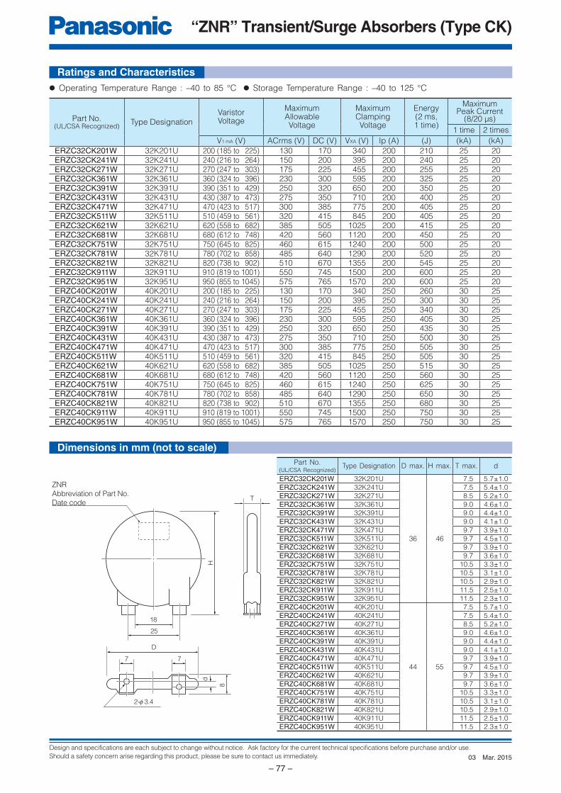
Design and specifications are each subject to change without notice. Ask factory for the current technical specifications before purchase and/or use.
Should a safety concern arise regarding this product, please be sure to contact us immediately.
“ZNR” Transient/Surge Absorbers (Type CK)
– 77 –
T
D
18
25
77
8
dH
2-f 3.4
ZNR
Abbreviation of Part No.
Date code
● Operating Temperature Range : –40 to 85 °C ● Storage Temperature Range : –40 to 125 °C
Part No. (UL/CSA Recognized)
Type DesignationVaristorVoltage
MaximumAllowableVoltage
MaximumClampingVoltage
Energy(2 ms,1 time)
MaximumPeak Current
(8/20 μs)
1 time 2 times
V1 mA (V) ACrms (V) DC (V) VXA (V) Ip (A) (J) (kA) (kA)
ERZC32CK201W 32K201U 200 (185 to 225) 130 170 340 200 210 25 20ERZC32CK241W 32K241U 240 (216 to 264) 150 200 395 200 240 25 20ERZC32CK271W 32K271U 270 (247 to 303) 175 225 455 200 255 25 20ERZC32CK361W 32K361U 360 (324 to 396) 230 300 595 200 325 25 20ERZC32CK391W 32K391U 390 (351 to 429) 250 320 650 200 350 25 20ERZC32CK431W 32K431U 430 (387 to 473) 275 350 710 200 400 25 20ERZC32CK471W 32K471U 470 (423 to 517) 300 385 775 200 405 25 20ERZC32CK511W 32K511U 510 (459 to 561) 320 415 845 200 405 25 20ERZC32CK621W 32K621U 620 (558 to 682) 385 505 1025 200 415 25 20ERZC32CK681W 32K681U 680 (612 to 748) 420 560 1120 200 450 25 20ERZC32CK751W 32K751U 750 (645 to 825) 460 615 1240 200 500 25 20ERZC32CK781W 32K781U 780 (702 to 858) 485 640 1290 200 520 25 20ERZC32CK821W 32K821U 820 (738 to 902) 510 670 1355 200 545 25 20ERZC32CK911W 32K911U 910 (819 to 1001) 550 745 1500 200 600 25 20ERZC32CK951W 32K951U 950 (855 to 1045) 575 765 1570 200 600 25 20ERZC40CK201W 40K201U 200 (185 to 225) 130 170 340 250 260 30 25ERZC40CK241W 40K241U 240 (216 to 264) 150 200 395 250 300 30 25ERZC40CK271W 40K271U 270 (247 to 303) 175 225 455 250 340 30 25ERZC40CK361W 40K361U 360 (324 to 396) 230 300 595 250 405 30 25ERZC40CK391W 40K391U 390 (351 to 429) 250 320 650 250 435 30 25ERZC40CK431W 40K431U 430 (387 to 473) 275 350 710 250 500 30 25ERZC40CK471W 40K471U 470 (423 to 517) 300 385 775 250 505 30 25ERZC40CK511W 40K511U 510 (459 to 561) 320 415 845 250 505 30 25ERZC40CK621W 40K621U 620 (558 to 682) 385 505 1025 250 515 30 25ERZC40CK681W 40K681U 680 (612 to 748) 420 560 1120 250 560 30 25ERZC40CK751W 40K751U 750 (645 to 825) 460 615 1240 250 625 30 25ERZC40CK781W 40K781U 780 (702 to 858) 485 640 1290 250 650 30 25ERZC40CK821W 40K821U 820 (738 to 902) 510 670 1355 250 680 30 25ERZC40CK911W 40K911U 910 (819 to 1001) 550 745 1500 250 750 30 25ERZC40CK951W 40K951U 950 (855 to 1045) 575 765 1570 250 750 30 25
Part No.(UL/CSA Recognized)
Type Designation D max. H max. T max. d
ERZC32CK201W 32K201U
36 46
7.5 5.7±1.0
ERZC32CK241W 32K241U 7.5 5.4±1.0
ERZC32CK271W 32K271U 8.5 5.2±1.0
ERZC32CK361W 32K361U 9.0 4.6±1.0
ERZC32CK391W 32K391U 9.0 4.4±1.0
ERZC32CK431W 32K431U 9.0 4.1±1.0
ERZC32CK471W 32K471U 9.7 3.9±1.0
ERZC32CK511W 32K511U 9.7 4.5±1.0
ERZC32CK621W 32K621U 9.7 3.9±1.0
ERZC32CK681W 32K681U 9.7 3.6±1.0
ERZC32CK751W 32K751U 10.5 3.3±1.0
ERZC32CK781W 32K781U 10.5 3.1±1.0
ERZC32CK821W 32K821U 10.5 2.9±1.0
ERZC32CK911W 32K911U 11.5 2.5±1.0
ERZC32CK951W 32K951U 11.5 2.3±1.0
ERZC40CK201W 40K201U
44 55
7.5 5.7±1.0
ERZC40CK241W 40K241U 7.5 5.4±1.0
ERZC40CK271W 40K271U 8.5 5.2±1.0
ERZC40CK361W 40K361U 9.0 4.6±1.0
ERZC40CK391W 40K391U 9.0 4.4±1.0
ERZC40CK431W 40K431U 9.0 4.1±1.0
ERZC40CK471W 40K471U 9.7 3.9±1.0
ERZC40CK511W 40K511U 9.7 4.5±1.0
ERZC40CK621W 40K621U 9.7 3.9±1.0
ERZC40CK681W 40K681U 9.7 3.6±1.0
ERZC40CK751W 40K751U 10.5 3.3±1.0
ERZC40CK781W 40K781U 10.5 3.1±1.0
ERZC40CK821W 40K821U 10.5 2.9±1.0
ERZC40CK911W 40K911U 11.5 2.5±1.0
ERZC40CK951W 40K951U 11.5 2.3±1.0
Ratings and Characteristics
Dimensions in mm (not to scale)
Mar. 201503

Design and specifications are each subject to change without notice. Ask factory for the current technical specifications before purchase and/or use.
Should a safety concern arise regarding this product, please be sure to contact us immediately.
“ZNR” Transient/Surge Absorbers (Type CK)
– 78 –
Current (A)
6000
4000
2000
1000
800
600
400
200
100
80
60
10-6 10-5 10-4 10-3 10-2 10-1 100 101 102 103 104 105
Vo
lta
ge
(V
)
Test Current Waveform 10-6 to 10-3 A: Direct Current 10-1 to 104 A: 8/20 μs
Max. Clamping VoltageMax. Leakage Current
ERZC32CK951WERZC32CK911WERZC32CK821WERZC32CK751WERZC32CK681WERZC32CK621W
ERZC32CK271W
ERZC32CK241WERZC32CK201W
ERZC32CK511WERZC32CK471WERZC32CK431WERZC32CK391WERZC32CK361W
ERZC32CK951WERZC32CK911WERZC32CK821WERZC32CK751WERZC32CK681WERZC32CK621W
ERZC32CK511WERZC32CK471WERZC32CK431WERZC32CK391WERZC32CK361W
ERZC32CK271WERZC32CK241WERZC32CK201W
Current (A)
6000
4000
2000
1000
800
600
400
200
100
80
60
10-6 10-5 10-4 10-3 10-2 10-1 100 101 102 103 104 105
Voltag
e (
V)
Test Current Waveform 10-6 to 10-3 A: Direct Current 10-1 to 104 A: 8/20 μs
Max. Clamping VoltageMax. Leakage Current
ERZC40CK951WERZC40CK911WERZC40CK821WERZC40CK751WERZC40CK681WERZC40CK621W
ERZC40CK271W
ERZC40CK241WERZC40CK201W
ERZC40CK511WERZC40CK471WERZC40CK431WERZC40CK391WERZC40CK361W
ERZC40CK271WERZC40CK241WERZC40CK201W
ERZC40CK951WERZC40CK911WERZC40CK821WERZC40CK751WERZC40CK681WERZC40CK621W
ERZC40CK511WERZC40CK471WERZC40CK431WERZC40CK391WERZC40CK361W
Typical Characteristics
(ERZC40CK201W to ERZC40CK951W)
Voltage vs. Current (ERZC32CK201W to ERZC32CK951W)
Mar. 201503

Design and specifications are each subject to change without notice. Ask factory for the current technical specifications before purchase and/or use.
Should a safety concern arise regarding this product, please be sure to contact us immediately.
“ZNR” Transient/Surge Absorbers (Type CK)
– 79 –
UL, CSA Rec og nized Components and The A.C. Rated Voltage
Part No.
(UL/CSA Recognized)
Maximum Allowable Voltage Rated Voltage (Vrms)
ACrms (V) DC (V) UL1449 CSA (Class 2221 01)
ERZC32CK201W 130 170 118 118
ERZC32CK241W 150 200 136 136
ERZC32CK271W 175 225 159 159
ERZC32CK361W 230 300 209 209
ERZC32CK391W 250 320 227 227
ERZC32CK431W 275 350 250 250
ERZC32CK471W 300 385 272 272
ERZC32CK511W 320 415 291 291
ERZC32CK621W 385 505 350 350
ERZC32CK681W 420 560 381 381
ERZC32CK751W 460 615 418 418
ERZC32CK781W 485 640 440 440
ERZC32CK821W 510 670 463 463
ERZC32CK911W 550 745 500 500
ERZC32CK951W 575 765 522 522
ERZC40CK201W 130 170 118 118
ERZC40CK241W 150 200 136 136
ERZC40CK271W 175 225 159 159
ERZC40CK361W 230 300 209 209
ERZC40CK391W 250 320 227 227
ERZC40CK431W 275 350 250 250
ERZC40CK471W 300 385 272 272
ERZC40CK511W 320 415 291 291
ERZC40CK621W 385 505 350 350
ERZC40CK681W 420 560 381 381
ERZC40CK751W 460 615 418 418
ERZC40CK781W 485 640 440 440
ERZC40CK821W 510 670 463 463
ERZC40CK911W 550 745 500 500
ERZC40CK951W 575 765 522 522
Mar. 201503
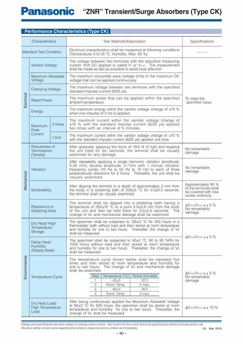
Design and specifications are each subject to change without notice. Ask factory for the current technical specifications before purchase and/or use.
Should a safety concern arise regarding this product, please be sure to contact us immediately.
“ZNR” Transient/Surge Absorbers (Type CK)
– 80 –
Characteristics Test Methods/Description Specifications
Standard Test ConditionElectrical characteristics shall be measured at following conditions (Temperature: 5 to 35 °C, Humidity: Max. 85 %).
———
Ele
ctri
cal
Varistor VoltageThe voltage between two terminals with the specified measuring current 1mA DC applied is called V1 or V1mA. The measurement shall be made as fast as possible to avoid heat affection.
To meet the specified value.
Maximum AllowableVoltage
The maximum sinusoidal wave voltage (rms) or the maximum DC voltage that can be applied continuously.
Clamping VoltageThe maximum voltage between two terminals with the specified standard impulse current (8/20 μs).
Rated PowerThe maximum power that can be applied within the specified ambient temperature.
EnergyThe maximum energy within the varistor voltage change of ±10 % when one impulse of 2 ms is applied.
MaximumPeakCurrent
2 timesThe maximum current within the varistor voltage change of ±10 % with the standard impulse current (8/20 μs) applied two times with an interval of 5 minutes.
1 timeThe maximum current within the varistor voltage change of ±10 % with the standard impulse current (8/20 μs) applied one time.
Mec
hani
cal
Robustness of Terminations(Tensile)
After gradually applying the force of 19.6 N (2 kgf) and keeping the unit fi xed for ten seconds, the terminal shall be visually examined for any damage.
No remarkabledamage
Vibration
After repeatedly applying a single harmonic vibration (amplitude: 0.35 mm): double amplitude: 0.7 mm with 1 minute vibration frequency cycles (10 Hz to 55 Hz to 10 Hz) to each of three perpendicular directions for 2 hours. Thereafter, the unit shall be visually examined.
No remarkabledamage
SolderabilityAfter dipping the terminal to a depth of approximately 3 mm from the body in a soldering bath of 230±5 °C for 5.0±0.5 seconds, the terminal shall be visually examined.
Approximately 95 % of the terminals shall be covered with new solder uniformly.
Resistance toSoldering Heat
The terminal shall be dipped into a soldering bath having a temperature of 350±10 °C to a point 4.0±0.8 mm from the body of the unit and then be held there for 3.0±0.5 seconds. The change of Vc and mechanical damage shall be examined.
ΔV1mA/V1mA < ± 5 %No remarkabledamage
Env
ironm
enta
l
Dry Heat/ HighTemperatureStorage
The specimen shall be subjected to 125±2 °C for 500 hours in a thermostatic bath without load and then stored at room temperature and humidity for one to two hours. Thereafter, the change of Vc shall be measured.
ΔV1mA/V1mA < ± 5 %
Damp Heat/Humidity(Steady State)
The specimen shall be subjected to 40±2 °C, 90 to 95 %RH for 1000 hours without load and then stored at room temperature and humidity for one to two hours. Thereafter, the change of Vc shall be measured.
Temperature Cycle
The temperature cycle shown below shall be repeated five times and then stored at room temperature and humidity for one to two hours. The change of Vc and mechanical damage shall be examined.
Step Temperature (°C) Period (minutes)
1 –25±3 30+3
2 Room Temp. 3 max.
3 85±2 30+3
4 Room Temp. 3 max.
ΔV1mA/V1mA < ± 5 %No remarkabledamage
Dry Heat Load/High TemperatureLoad
After being continuously applied the Maximum Allowable Voltage at 85±2 °C for 500 hours, the specimen shall be stored at room temperature and humidity for one to two hours. Thereafter, the change of Vc shall be measured.
ΔV1mA/V1mA < ± 10 %
0
0
Performance Characteristics (Type CK)
Mar. 201503
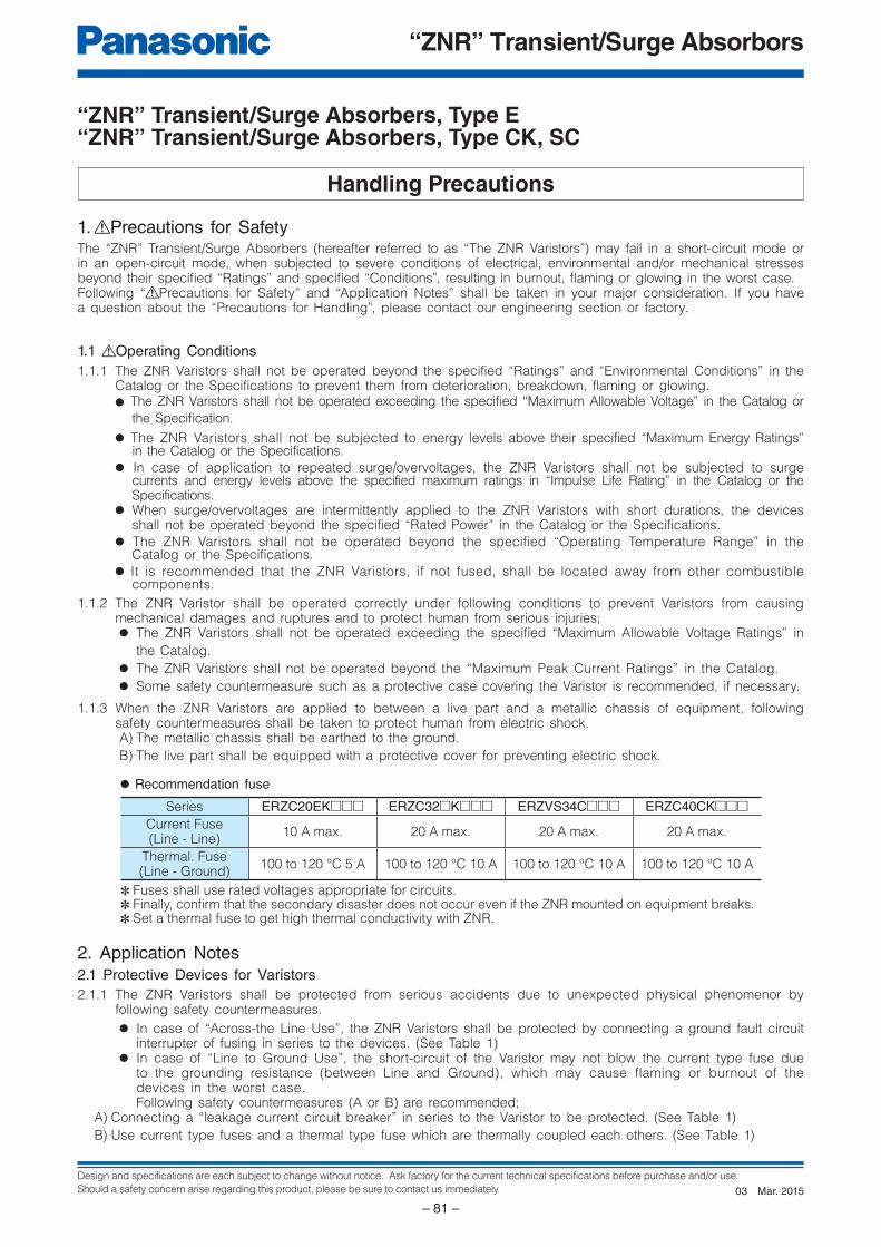
Design and specifications are each subject to change without notice. Ask factory for the current technical specifications before purchase and/or use.
Should a safety concern arise regarding this product, please be sure to contact us immediately.
“ZNR” Transient/Surge Absorbors
– 81 –
“ZNR” Transient/Surge Absorbers, Type E“ZNR” Transient/Surge Absorbers, Type CK, SC
Handling Precautions
1. Precautions for SafetyThe “ZNR” Transient/Surge Absorbers (hereafter referred to as “The ZNR Varistors”) may fail in a short-circuit mode or in an open-circuit mode, when subjected to severe conditions of electrical, environmental and/or me chanical stresses beyond their specifi ed “Ratings” and specifi ed “Conditions”, resulting in burnout, fl aming or glowing in the worst case.Following “ Precautions for Safety” and “Application Notes” shall be taken in your major consideration. If you have a question about the “Precautions for Handling”, please contact our engineering section or factory.
1.1 Operating Conditions1.1.1 The ZNR Varistors shall not be operated beyond the specified “Ratings” and “Environmental Conditions” in the
Catalog or the Specifications to prevent them from deterioration, breakdown, flaming or glowing.
● The ZNR Varistors shall not be operated exceeding the specifi ed “Maximum Allowable Voltage” in the Catalog or
the Specifi cation.
● The ZNR Varistors shall not be subjected to energy levels above their specified “Maximum Energy Ratings” in the Catalog or the Specifications.
● In case of application to repeated surge/overvoltages, the ZNR Varistors shall not be subjected to surge currents and energy levels above the specified maximum ratings in “Impulse Life Rating” in the Catalog or the Specifications.
● When surge/overvoltages are intermittently applied to the ZNR Varistors with short durations, the devices shall not be operated beyond the specified “Rated Power” in the Catalog or the Specifications.
● The ZNR Varistors shall not be operated beyond the specified “Operating Temperature Range” in the Catalog or the Specifications.
● It is recommended that the ZNR Varistors, if not fused, shall be located away from other combustible components.
1.1.2 The ZNR Varistor shall be operated correctly under following conditions to prevent Varistors from causing mechanical damages and ruptures and to protect human from serious injuries;● The ZNR Varistors shall not be operated exceeding the specified “Maximum Allowable Voltage Ratings” in
the Catalog.
● The ZNR Varistors shall not be operated beyond the “Maximum Peak Current Ratings” in the Catalog.
● Some safety countermeasure such as a protective case covering the Varistor is recommended, if necessary.
1.1.3 When the ZNR Varistors are applied to between a live part and a metallic chassis of equipment, following safety countermeasures shall be taken to protect human from electric shock.A) The metallic chassis shall be earthed to the ground.
B) The live part shall be equipped with a protective cover for preventing electric shock.
✽ Fuses shall use rated voltages appropriate for circuits.✽ Finally, confi rm that the secondary disaster does not occur even if the ZNR mounted on equipment breaks.✽ Set a thermal fuse to get high thermal conductivity with ZNR.
● Recommendation fuse
Series ERZC20EK□□□ ERZC32□K□□□ ERZVS34C□□□ ERZC40CK□□□Current Fuse(Line - Line)
10 A max. 20 A max. 20 A max. 20 A max.
Thermal. Fuse(Line - Ground)
100 to 120 °C 5 A 100 to 120 °C 10 A 100 to 120 °C 10 A 100 to 120 °C 10 A
2. Application Notes2.1 Protective Devices for Varistors2.1.1 The ZNR Varistors shall be protected from serious accidents due to unexpected physical phenomenor by
following safety countermeasures.
● In case of “Across-the Line Use”, the ZNR Varistors shall be protected by connecting a ground fault circuit interrupter of fusing in series to the devices. (See Table 1)
● In case of “Line to Ground Use”, the short-circuit of the Varistor may not blow the current type fuse due to the grounding resistance (between Line and Ground), which may cause flaming or burnout of the devices in the worst case.
Following safety countermeasures (A or B) are recommended;A) Connecting a “leakage current circuit breaker” in series to the Varistor to be protected. (See Table 1)
B) Use current type fuses and a thermal type fuse which are thermally coupled each others. (See Table 1)
Mar. 201503
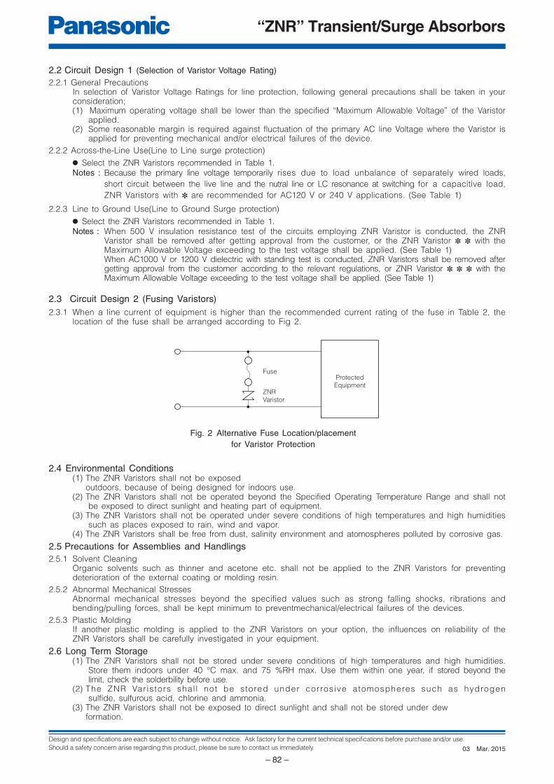
Design and specifications are each subject to change without notice. Ask factory for the current technical specifications before purchase and/or use.
Should a safety concern arise regarding this product, please be sure to contact us immediately.
“ZNR” Transient/Surge Absorbors
– 82 –
Fuse
ZNR
Varistor
Protected
Equipment
2.2 Circuit Design 1 (Selection of Varistor Voltage Rating)
2.2.1 General Precautions In selection of Varistor Voltage Ratings for line protection, following general precautions shall be taken in your
consideration;(1) Maximum operating voltage shall be lower than the specified “Maximum Allowable Voltage” of the Varistor
applied.(2) Some reasonable margin is required against fluctuation of the primary AC line Voltage where the Varis tor is
applied for preventing mechanical and/or electrical failures of the device.
2.2.2 Across-the-Line Use(Line to Line surge protection)
● Select the ZNR Varistors recommended in Table 1.Notes : Because the primary line voltage temporarily rises due to load unbalance of separately wired loads,
short circuit between the live line and the nutral line or LC resonance at switching for a capacitive load,
ZNR Varistors with ✽ are recommended for AC120 V or 240 V applications. (See Table 1)
2.2.3 Line to Ground Use(Line to Ground Surge pro tec tion)
● Select the ZNR Varistors recommended in Table 1.Notes : When 500 V insulation resistance test of the circuits employing ZNR Varistor is conducted, the ZNR
Varistor shall be removed after getting approv al from the customer, or the ZNR Varistor ✽ ✽ with the Maximum Allowable Voltage ex ceeding to the test voltage shall be applied. (See Table 1)
When AC1000 V or 1200 V dielectric with standing test is conducted, ZNR Varistors shall be removed after getting approval from the customer according to the relevant regulations, or ZNR Varistor ✽ ✽ ✽ with the Maximum Allowable Volt age exceeding to the test voltage shall be applied. (See Table 1)
2.3 Circuit Design 2 (Fusing Varistors)2.3.1 When a line current of equipment is higher than the recommended current rating of the fuse in Table 2, the
location of the fuse shall be arranged according to Fig 2.
Fig. 2 Alternative Fuse Location/placementfor Varis tor Pro tec tion
2.4 Environmental Conditions(1) The ZNR Varistors shall not be exposed outdoors, because of being designed for in doors use.(2) The ZNR Varistors shall not be operated beyond the Specified Operating Temperature Range and shall not
be exposed to direct sunlight and heating part of equipment.(3) The ZNR Varistors shall not be operated under se vere conditions of high temperatures and high humidities
such as places exposed to rain, wind and vapor.(4) The ZNR Varistors shall be free from dust, salinity environment and atomospheres polluted by corrosive gas.
2.5 Precautions for Assemblies and Handlings2.5.1 Solvent Cleaning Organic solvents such as thinner and acetone etc. shall not be applied to the ZNR Varistors for preventing
deterioration of the external coating or molding resin.
2.5.2 Abnormal Mechanical Stresses Abnormal mechanical stresses beyond the spec i fied values such as strong falling shocks, ribrations and
bending/pulling forces, shall be kept minimum to preventmechanical/electrical failures of the devices.
2.5.3 Plastic Molding If another plastic molding is applied to the ZNR Varistors on your option, the influences on reliability of the
ZNR Varistors shall be carefully investigated in your equipment.
2.6 Long Term Storage(1) The ZNR Varistors shall not be stored under severe conditions of high temperatures and high humidities.
Store them indoors under 40 °C max. and 75 %RH max. Use them within one year, if stored beyond the limit, check the solderbility before use.
(2) The ZNR Varistors shal l not be stored under corrosive atomospheres such as hydrogensulfide, sulfurous acid, chlorine and ammonia.
(3) The ZNR Varistors shall not be exposed to direct sunlight and shall not be stored under dew formation.
Mar. 201503

Design and specifications are each subject to change without notice. Ask factory for the current technical specifications before purchase and/or use.
Should a safety concern arise regarding this product, please be sure to contact us immediately.
“ZNR” Transient/Surge Absorbors
– 83 –
f ZNR1
Protected
Equipment
f
ZNR1Protected
Equipment
ZNR2
Thermal. FuseThermal
coupling
f ZNR3
Protected
Equipment
f ZNR3
Protected
Equipment
ZNR4
Thermal. Fuse
Thermal
coupling
f
f
2.7 Regarding to “Safety Regulations of the Varistors”In case of applications to UL and CSA standards, refer to “Application Notes for UL and CSA Recognized” ZNR “Varistors”
2.8 Parallel Capacitances of the ZNR VaristorsThe ZNR Varistors have relatively high capacitances specifi ed in the individual specifi cations, special consideration
shall be taken into account in applications to high frequency transmission lines or circuits.
Table 1. Application Examples
Con
nec t
ions
Across-the-Line/Line to Line Protection Line to Line and Line to Ground Protection
D.C.
A.C. Single phase
D.C.
A.C. Single phase
A.C. 3 phase A.C. 3 phase
Sel
ectio
n E
xam
ples
Across the Line Use/Line to Line Line to Ground Use
ZNRNominal
Line Voltage
Part Number of ZNRZNR
Nominal
Line Voltage
Part Number of ZNR
Type E, CK, SC Type E, CK, SC
ZNR1
ZNR3
AC 100 V
ERZC□□EKERZC□□CKERZVS34C
201
241
271
ZNR2
ZNR4
AC 100 V
to AC 220 VERZC□□EKERZC□□CKERZVS34C
471
511
821 ✽✽AC 120 V
241
271 ✽
AC 200 V
to AC 220 V471
AC 240 V511
821 ✽✽AC 240 V 511
f : fuse
f : fuse
f : fuse
f : fuse
Mar. 201503

Design and specifications are each subject to change without notice. Ask factory for the current technical specifications before purchase and/or use.
Should a safety concern arise regarding this product, please be sure to contact us immediately.
“ZNR” Transient/Surge Absorbers (Type P)
– 84 –
E
1
R
2
Z
3 4 5 6 7 8 9 10 11 12
Element Size Type Design No.Nominal
Varistor Voltage
Tolerance
A P K
Product Code Series
Explanation of Part Numbers
Recommended Applications
Protection of semiconductor devices used for the electronic equipment includes:
● Broadcasting, communication equipment● Traffi c or railroad systems● Automatic control devices for power distribution● Waterworks● Protection of motor coils, vacuum switches
“ZNR” Transient/Surge Absorbers
Type : P
■ As for Minimum Quantity / Packing Unit
Please see Related Information
Part No.
Varistor
Voltage
Maximum
Allowable
Voltage
Maximum
Clamping
Voltage
Maximum
Peak Current
(8/20 μs, 2 times)
Energy
(2 ms, 1 time)
Typical
Capacitance
(Reference)
V1 mA (V) ACrms (V) DC (V) V100 A (V) (A) (J) at 1 kHz (pF)
ERZA20PK251 250±10 % 130 180 410 5000 90 1200
ERZA20PK501 500±10 % 260 360 825 5000 150 600
ERZA20PK102 1000±10 % 520 730 1650 5000 240 300
● Operating Temperature Range : –25 to 70 °C● Storage Temperature Range : –25 to 70 °C
Ratings and Characteristics
ZNR Transient/Surge Absorber, Type P is a suitable
device to protect various electric equipment and
semiconductive devices from instantaneous over-voltages
like switching surges and induced lightnings. The Type P
is characterized by the unique construction of plug-in type
with a deterioration indicator.
● RoHS compliant
Aug. 201503

Design and specifications are each subject to change without notice. Ask factory for the current technical specifications before purchase and/or use.
Should a safety concern arise regarding this product, please be sure to contact us immediately.
“ZNR” Transient/Surge Absorbers (Type P)
– 85 –
Life indicator
Mounting hole
Mo
un
tin
g p
itc
h
M4
88
78
f 30
f 4.5
66
16
7
47
3
f 9
NP
4000
3000
2000
1000900800700
600
500
400
300
200
100908070
60
10-6 10-5 10-4 10-3 10-2 10-1 1 10 102 103 104 105
Current (A)
Voltag
e (
V)
ERZA20PK102
ERZA20PK501
ERZA20PK251
Test Current Waveform 10-6 to 10-3 A: Direct Current 10-1 to 104 A: 8/20 μs
Max. Clamping VoltageMax. Leakage Current
ERZA20PK102
ERZA20PK501
ERZA20PK251
Dimensions in mm (not to scale)
Voltage vs. Current (ERA20PK251 to ERZA20PK102)
Typical Characteristics
Aug. 201503
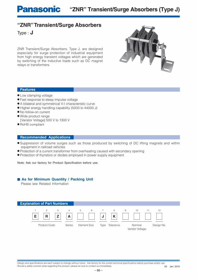
Design and specifications are each subject to change without notice. Ask factory for the current technical specifications before purchase and/or use.
Should a safety concern arise regarding this product, please be sure to contact us immediately.
“ZNR” Transient/Surge Absorbers (Type J)
– 86 –
E
1
R
2
Z
3 4 5 6 7 8 9 10 11 12
Element Size Type Design No.Nominal
Varistor Voltage
Tolerance
A J K
Product Code Series
Explanation of Part Numbers
Features
● Low clamping voltage● Fast response to steep impulse voltage● A bilateral and symmetrical V-I characteristic curve● Higher energy handling capability (5000 to 44000 J)● No follow-on current● Wide product range
[Varistor Voltage] 500 V to 1300 V● RoHS compliant
“ZNR” Transient/Surge Absorbers
Type : J
■ As for Minimum Quantity / Packing Unit
Please see Related Information
ZNR Transient/Surge Absorbers, Type J, are designed
especially for surge protection of industrial equipment
from high energy transient voltages which are generated
by switching of the inductive loads such as DC magnet
relays or transformers.
Recommended Applications
● Suppression of volume surges such as those produced by switching of DC lifting magnets and within equipment in railroad vehicles
● Protection of a current transformer from overheating caused with secondary opening● Protection of thyristors or diodes employed in power supply equipment
Note: Ask our factory for Product Specifi cation before use.
Jan. 201502

Design and specifications are each subject to change without notice. Ask factory for the current technical specifications before purchase and/or use.
Should a safety concern arise regarding this product, please be sure to contact us immediately.
“ZNR” Transient/Surge Absorbers (Type J)
– 87 –
Imp
uls
e C
urr
ent
(A)
Impulse Width
1s100 ms10 ms1 ms100 μs10 μs
106
105
104
103
102
10
1
0.1
0.01
10 5
10 4 10 3
10 2 10
1
T
T
1.0
1.0
0
00.5
(10 to 40 μs)
(100 μsto 1s)
Current (A)
Voltag
e (
V)
10–6 10–5 10–4 10–3 10–2 10–1 100 101 102 103 104 105
100
200
300
500
700
1,000
2,000
3,000
5,000
Max.Leakage Current Max. Clamping Voltage
ERZA80JK112
ERZA80JK112
ERZA80JK561
ERZA80JK122 ERZA80JK561
ERZA80JK122
Test current waveform 10–4 to 10–3 A: Direct current 10–1 to 104 A: 8/20 μs
Voltage vs. Current Impulse Derating
Typical Characteristics
Part No.
VaristorVoltage
MaximumAllowableVoltage
MaximumClampingVoltage
Energy(Derated sinusoidal
wave, 1 time)
MaximumPeak Current
(4/10 μs, 2 times)
TypicalCapacitance(Reference)
V1 mA (V) ACrms (V) DC (V) V100 A (V) (J) (kA) at 1 kHz (pF)
ERZA80JK561
560
(505 to 615)250 350 925
5000 80 9800
ERZA80JK561A 10000 80 × 2 19600
ERZA80JK561B 15000 80 × 3 29400
ERZA80JK561C 20000 80 × 4 39200
ERZA80JK112
1100
(980 to 1200)485 680 1800
10000 80 4800
ERZA80JK112A 20000 80 × 2 9600
ERZA80JK112B 30000 80 × 3 14400
ERZA80JK112C 40000 80 × 4 19200
ERZA80JK122
1250
(1120 to 1380)550 775 2070
11000 80 4400
ERZA80JK122A 22000 80 × 2 8800
ERZA80JK122B 33000 80 × 3 13200
ERZA80JK122C 44000 80 × 4 17600
● Operating Temperature Range : –25 to 70 °C● Storage Temperature Range : –25 to 110 °C
Ratings and Characteristics
Jan. 201502

Design and specifications are each subject to change without notice. Ask factory for the current technical specifications before purchase and/or use.
Should a safety concern arise regarding this product, please be sure to contact us immediately.
“ZNR” Transient/Surge Absorbers (Type J)
– 88 –
M6 A 5.5 mm2 Terminal
BC
HoleBar
85
14
0
ZNR connection
7±1.0
7±
1.0
96±0.2
Terminal
Name plate
□1
10
8.5
62
40±0.431
8 26
39
Terminal
M6 A 5.5 mm2 Terminal
BC
HoleBar
85
140
ZNR connection
7±1.0
7±
1.0
96±0.2
Terminal
Name plate
□110
8.5
62
40±0.431
8 26
39
Terminal
M6 A 5.5 mm2 Terminal
BC
HoleBar
85
14
0
ZNR connection
7±1.0
7±
1.0
96±0.2
Terminal
Name plate
□1
10
8.5
62
40±0.431
8 26
39
Terminal
M6 A 5.5 mm2 Terminal
BC
HoleBar
85
14
0
ZNR connection
7±1.0
7±
1.0
96±0.2
Terminal
Name plate
□1
10
8.5
62
40±0.431
8 26
39
Terminal
Dimensions in mm (not to scale)
ERZA80JK□□□A ERZA80JK□□□C
ERZA80JK□□ ERZA80JK□□□B
Part No. A B C
ERZA80JK561 14.0 125.0±4.0 161.0±4.0
ERZA80JK561A 14.0 138.0±8.0 174.0±8.0
ERZA80JK561B 40.0 151.0±8.0 187.0±8.0
ERZA80JK561C 40.0 164.0±8.0 200.0±8.0
ERZA80JK112 19.0 130.0±4.0 166.0±4.0
ERZA80JK112A 19.0 148.0±8.0 184.0±8.0
ERZA80JK112B 56.0 167.0±8.0 203.0±8.0
ERZA80JK112C 56.0 185.0±8.0 221.0±8.0
ERZA80JK122 21.0 132.0±4.0 168.0±4.0
ERZA80JK122A 21.0 152.0±8.0 188.0±8.0
ERZA80JK122B 61.0 172.0±8.0 208.0±8.0
ERZA80JK122C 61.0 192.0±8.0 228.0±8.0
Jan. 201502
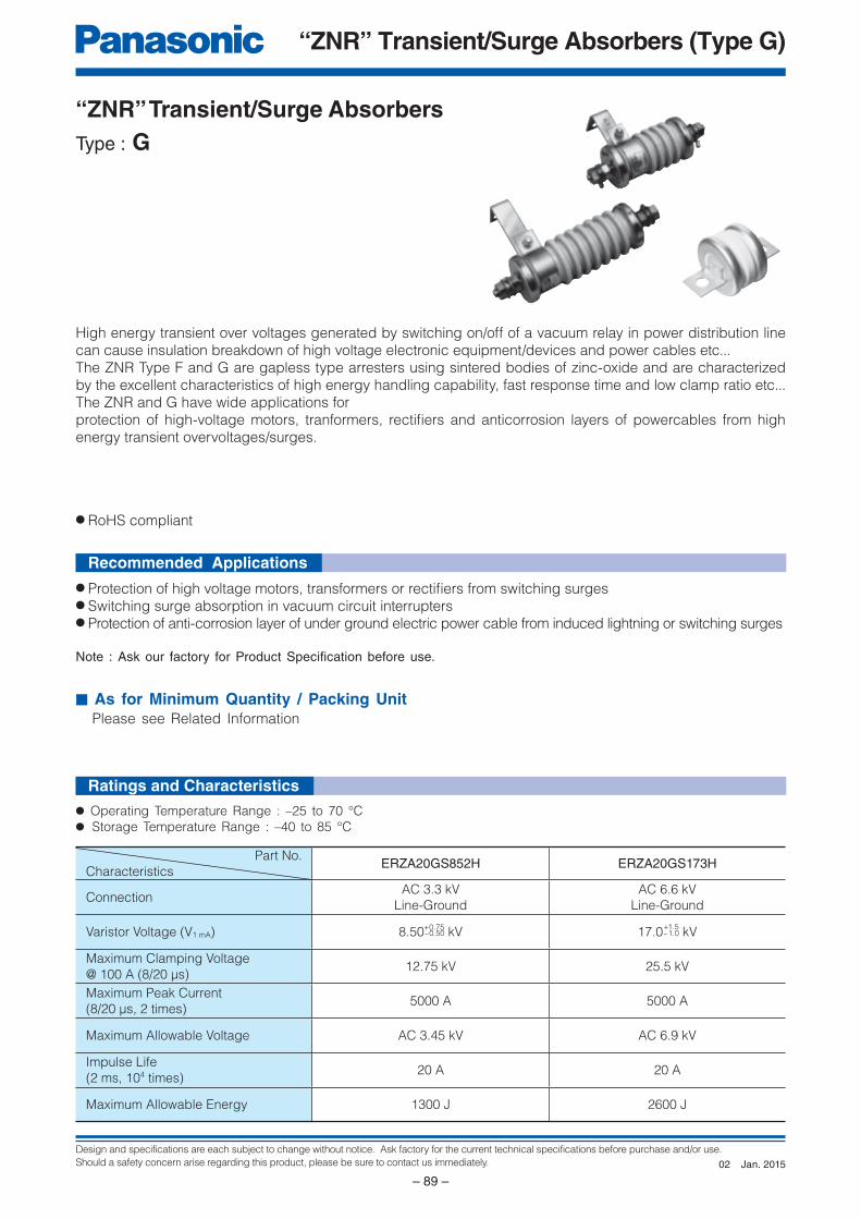
Design and specifications are each subject to change without notice. Ask factory for the current technical specifications before purchase and/or use.
Should a safety concern arise regarding this product, please be sure to contact us immediately.
“ZNR” Transient/Surge Absorbers (Type G)
– 89 –
● RoHS compliant
“ZNR” Transient/Surge Absorbers
Type : G
■ As for Minimum Quantity / Packing Unit
Please see Related Information
High energy transient over voltages generated by switching on/off of a vacuum relay in power distribution line
can cause insulation breakdown of high voltage electronic equipment/devices and power cables etc...
The ZNR Type F and G are gapless type arresters using sintered bodies of zinc-oxide and are characterized
by the excellent characteristics of high energy handling capability, fast response time and low clamp ratio etc...
The ZNR and G have wide applications for
protection of high-voltage motors, tranformers, rectifi ers and anticorrosion layers of powercables from high
energy transient overvoltages/surges.
Recommended Applications
● Protection of high voltage motors, transformers or rectifi ers from switching surges● Switching surge absorption in vacuum circuit interrupters● Protection of anti-corrosion layer of under ground electric power cable from induced lightning or switching surges
Note : Ask our factory for Product Specifi cation before use.
Part No.
CharacteristicsERZA20GS852H ERZA20GS173H
ConnectionAC 3.3 kV
Line-Ground
AC 6.6 kV
Line-Ground
Varistor Voltage (V1 mA) 8.50−0.50 kV 17.0−1.0 kV
Maximum Clamping Voltage
@ 100 A (8/20 μs) 12.75 kV 25.5 kV
Maximum Peak Current
(8/20 μs, 2 times)5000 A 5000 A
Maximum Allowable Voltage AC 3.45 kV AC 6.9 kV
Impulse Life
(2 ms, 104 times)20 A 20 A
Maximum Allowable Energy 1300 J 2600 J
+0.75 +1.5
● Operating Temperature Range : –25 to 70 °C● Storage Temperature Range : –40 to 85 °C
Ratings and Characteristics
Jan. 201502
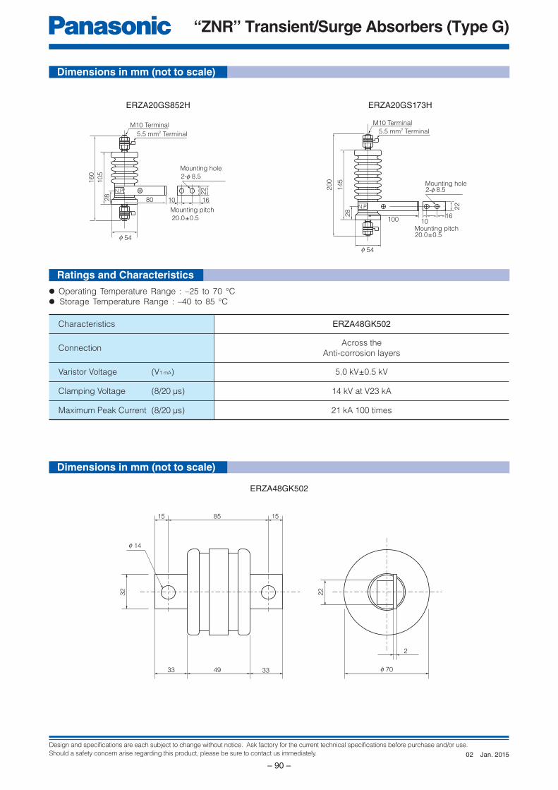
Design and specifications are each subject to change without notice. Ask factory for the current technical specifications before purchase and/or use.
Should a safety concern arise regarding this product, please be sure to contact us immediately.
“ZNR” Transient/Surge Absorbers (Type G)
– 90 –
N.P 22
16
Mounting hole
2-f 8.5
Mounting pitch
20.0±0.5
80 10
f 54
28
16
0
10
5
M10 Terminal
5.5 mm2 Terminal
20
0
14
5
100
f 54
Mounting hole2-f 8.5
Mounting pitch 20.0±0.5
M10 Terminal
5.5 mm2 Terminal
N.P
16
22
28
10
f 14
15 1585
49 3333
32
f 70
2
22
ERZA20GS852H ERZA20GS173H
ERZA48GK502
Characteristics ERZA48GK502
ConnectionAcross the
Anti-corrosion layers
Varistor Voltage (V1 mA) 5.0 kV±0.5 kV
Clamping Voltage (8/20 μs) 14 kV at V23 kA
Maximum Peak Current (8/20 μs) 21 kA 100 times
Dimensions in mm (not to scale)
Dimensions in mm (not to scale)
● Operating Temperature Range : –25 to 70 °C● Storage Temperature Range : –40 to 85 °C
Ratings and Characteristics
Jan. 201502

Design and specifications are each subject to change without notice. Ask factory for the current technical specifications before purchase and/or use.
Should a safety concern arise regarding this product, please be sure to contact us immediately.
Surge Absorber Units
– 91 –
● RoHS compliant
“ZNR” Surge Absorber Units
■ As for Minimum Quantity / Packing Unit
Please see Related Information
The Surge Absorber Unit contains Y, Δ or p connected ZNRs surge absorbers (and, if necessary, a circuit
breaker) in a box.
These Surge Absorber Units are designed for surge protection of industrial electric equipment where reliability
is essential.
Recommended Applications
Surge Protection of● Railway/traffi c signal control systems● Distribution line control systems● Broadcasting systems, communication systems● Measuring instruments● Controllers of low voltage distribution line● Controllers of waterworks
Note : Ask our factory for Product Specifi cation before use.
Jan. 201504

Design and specifications are each subject to change without notice. Ask factory for the current technical specifications before purchase and/or use.
Should a safety concern arise regarding this product, please be sure to contact us immediately.
Surge Absorber Units
– 92 –
Type D (other : Type E)
Eq
uip
ment
Eq
uip
ment
Type D (other : Type E)
ZNR Surge Absorber Units
ApplicationMaximum
PeakCurrent
RatedVoltage
Circuits
Single-phase two-wire system Single-phase three-wire system Three-phase three-wire system Three-phase four-wire system
Part No.Dim.
Part No.Dim.
Part No.Dim.
Part No.Dim.
Connection Connection Connection Connection
For
Power
Source
5000 A
AC 100/
120 V
ERZA1P251ASAA
ERZA2P251ASAB
ERZA4P251ASAB
1 2 4
ERZA1P251BC✽ C
5
ERZA1P251AR✽✽ C
6
AC 200/
220/240 VERZA1P501AS
AERZA2P501AS
BERZA3P501AS
BERZA4P501AS
B
1 2 3 4
AC 400/
440 VERZA1P102AS
BERZA3P102AS
BERZA4P102AS
1 3 4
20000 A
AC 100/
120 VERZA1E271ASA
AERZA2E271AS
BERZA4E271AS
B
7 8 10
AC 200/
220/240 VERZA1E471ASA
AERZA2E471AS
BERZA3E471AS
BERZA4E471AS
B
7 8 9 10
AC 400/
440 VERZA1E102AS
BERZA3E102AS
BERZA4E102AS
B
7 9 10
50000 A
AC 100/
120 VERZA1E271BS
BERZA2E271BS
BERZA4E271BS
B
7 8 10
AC 200/
220/240 VERZA1E471BS
BERZA2E471BS
BERZA3E471BS
BERZA4E471BS
B
7 8 9 10
AC 400/
440 VERZA1E102BS
BERZA3E102BS
BERZA4E102BS
B
7 9 10
✽ p connection with inductors (specified current: 2 A) ✽✽ p connection with resistors (specified current: 2 A)
ApplicationMaximum
PeakCurrent
RatedVoltage
Part No. Dimensions Connection
For signal system(Line to Line andLine to Ground use)
5000 A
DC 12 V ERZA5F220AC
D
Coil: 1 mH max.
Max. continuous current: 0.6 A
DC 24 V ERZA5F390AC
DC 48 V ERZA5F680AC
DC 80 V ERZA5F101AC
DC 100 V ERZA5F201ACA
For signal system(Line to Line use only)
5000 A
DC 12 V ERZA5F220BC
C
Coil: 1 mH max.
Max. continuous current: 0.6 A
DC 24 V ERZA5F390BC
DC 48 V ERZA5F680BC
DC 80 V ERZA5F101BC
DC 100 V ERZA5F201BC
Jan. 201504

Design and specifications are each subject to change without notice. Ask factory for the current technical specifications before purchase and/or use.
Should a safety concern arise regarding this product, please be sure to contact us immediately.
Surge Absorber Units
– 93 –
300
120
250
(A)
400
120
300
(B)
Mounting pitch
85
83
105
(D)
160
135
3-f 6
Mountin
g p
itch
Mounting pitch
85
83
105
(C)
160
135
3-f 6
Mountin
g p
itch
Dimensions in mm (not to scale)
Jan. 201504

Design and specifications are each subject to change without notice. Ask factory for the current technical specifications before purchase and/or use.
Should a safety concern arise regarding this product, please be sure to contact us immediately.
Surge Absorber Units
– 94 –
(1)
L1
L2
E
L1 L2
Equipment
L1 N L2
NL2
(2)
EEquipment
L1
R
S
E
(9)
T
Equipment
R TS
R
S T N
S
TNE
R
(10)Equipment
L1 L2
L1
L2
E
(7)
Equipment
L1
N
E
(8)
L2
Equipment
L1 L2N
L1
L2
Inductance : 1 mH max.
Max. continuous current : 2 A
(5)
EquipmentL1
L2
Resistance : 0.3 Ω
Max. continuous current : 2 A
(6)
Equipment
R
S T N
S
T
N
E
R
(4)Equipment
R S T
S
T
(3)
EEquipment
R
Circuit Diagrams
Jan. 201504

Design and specifications are each subject to change without notice. Ask factory for the current technical specifications before purchase and/or use.
Should a safety concern arise regarding this product, please be sure to contact us immediately.
“ZNR” Transient/Surge Absorbers (Type E/J)
– 95 –
● RoHS compliant
“ZNR” Transient/Surge Absorbers,For Thyristor Protection
Type : EType : J
■ As for Minimum Quantity / Packing Unit
Please see Related Information
“ZNR” Transient/Surge Absorber for thyristors is especially designed to protect SCR power controllers and
SCR power sources from high energy transient over voltages.
The ZNR is smaller in size and excellent in the clamping voltage characteristics as compared with a
conventional selenium surge absorber.
Type E is for relatively low handling capacity of trans-former and Type J is for heavy duty use.
Recommended Applications
● Surge protection of SCR✽ power controllers● Surge protection of SCR✽ power sources
✽ SCR = Silicone Controlled Rectifi ers
Note : Ask our factory for Product Specifi cation before use.
Type E
Type J
Jan. 201504

Design and specifications are each subject to change without notice. Ask factory for the current technical specifications before purchase and/or use.
Should a safety concern arise regarding this product, please be sure to contact us immediately.
“ZNR” Transient/Surge Absorbers (Type E/J)
– 96 –
24ISO
M4
L
W
12
H
ZNR
5
4.3
14
Part No.
Date code
Dot
“ZNR” Transient/Surge Absorbers, Type E
Part No.
VaristorVoltage
MaximumAllowableVoltage
MaximumClampingVoltage
Impulse Life(2 ms, 10
4 times)
CommutationSurge Ratio
V1 mA (V) ACrms (V) DC (V) VIp (V) Ip (A) (A) ——
ERZC20EK511P 498 to 542 242 342 760
10 10
1.45
ERZC20EK541P 523 to 560 264 373 785 1.40
ERZC20EK681P 630 to 678 330 467 950 1.35
ERZC20EK821P 788 to 848 412 583 1185 1.35
ERZC20EK911P 840 to 904 440 622 1265 1.35
ERZC20EK102P 945 to 1017 495 700 1425 1.35
ERZC20EK112P 1051 to 1181 550 775 1655 1.35
ERZC32EK511P 498 to 542 242 342 760
20 20
1.45
ERZC32EK541P 523 to 560 264 373 785 1.40
ERZC32EK681P 630 to 678 330 467 950 1.35
ERZC32EK821P 788 to 848 412 583 1185 1.35
ERZC32EK911P 840 to 904 440 622 1265 1.35
ERZC32EK102P 945 to 1017 495 700 1425 1.35
ERZC32EK112P 1051 to 1181 550 775 1655 1.35
Part No. W H L
ERZC20EK□□□P 48±1 42±1 39±1
ERZC32EK□□□P 60±1 55±1 51±1
Ratings and Characteristics (Type E)
● Operating Temperature Range : –40 to 85 °C
● Storage Temperature Range : –40 to 110 °C
Dimensions in mm (not to scale) (Type E)
(Unit : mm)
Jan. 201504

Design and specifications are each subject to change without notice. Ask factory for the current technical specifications before purchase and/or use.
Should a safety concern arise regarding this product, please be sure to contact us immediately.
“ZNR” Transient/Surge Absorbers (Type E/J)
– 97 –
A
B
20
46
2214
3
6.5
104±1
M4
60
C
14
1±
1
N.P.
20
46
2214
3
6.5A
B
104±1
M4
60
C
12
2±
1
N.P.
Style (1) Style (2)
Part No. Connection
Maximum
Allowable
Voltage
Maximum
Clamping
Voltage
Impulse Life
(2 ms,
104 times) Commutation
Surge Ratio
Dimensions in mm
ACrms
(V)
DC
(V)
VIp
(V)
Ip
(A)(A) Style A B C
ERZU11JP511
Single 242 342 760
40 40
1.45 (1)
88 108
20
EZRU12JP511 70 70 104 124
ERZU13JP511 95 95 121 141
ERZU14JP511 125 125 138 158
ERZU15JP511 150 150 155 175
ERZU16JP511 180 180 172 192
ERZU17JP511 210 210 189 209
ERZU11JP511B
Delta 242 — 760
40 40
1.45 (2)
120 140
20ERZU12JP511B 70 70 169 189
ERZU13JP511B 95 95 219 239
ERZU14JP511B 125 125 268 288
ERZU11JP541
Single 264 373 785
40 40
1.40 (1)
88 108
20
ERZU12JP541 70 70 105 125
ERZU13JP541 95 95 122 142
ERZU14JP541 125 125 139 159
ERZU15JP541 150 150 156 176
ERZU16JP541 180 180 172 192
ERZU17JP541 210 210 189 209
ERZU11JP541B
Delta 264 — 785
40 40
1.40 (2)
121 141
20ERZU12JP541B 70 70 171 191
ERZU13JP541B 95 95 221 241
ERZU14JP541B 125 125 270 290
“ZNR” Transient/Surge Absorbers, Type J
Ratings and Characteristics (Type J)
● Operating Temperature Range : –40 to 70 °C
● Storage Temperature Range : –40 to 110 °C
Dimensions in mm (not to scale)
(Unit : mm)(Unit : mm)
Jan. 201504

Design and specifications are each subject to change without notice. Ask factory for the current technical specifications before purchase and/or use.
Should a safety concern arise regarding this product, please be sure to contact us immediately.
“ZNR” Transient/Surge Absorbers (Type E/J)
– 98 –
Part No. Connection
Maximum
Allowable
Voltage
Maximum
Clamping
Voltage
Impulse Life
(2 ms,
104 times) Commutation
Surge Ratio
Dimensions in mm
ACrms
(V)
DC
(V)
VIp
(V)
Ip
(A)(A) Style A B C
ERZU21JP102
Single 484 684 1520
40 40
1.45 (1)
102 122
20
ERZU22JP102 70 70 135 155
ERZU23JP102 95 95 168 188
ERZU24JP102 125 125 199 219
ERZU25JP102 150 150 230 250
ERZU26JP102 180 180 261 281
ERZU21JP102BDelta 484 — 1520
40 401.45 (2)
166 18620
ERZU22JP102B 70 70 261 281
ERZU21JP112
Single 528 746 1570
40 40
1.40 (1)
103 123
20
ERZU22JP112 70 70 136 156
ERZU23JP112 95 95 169 189
ERZU24JP112 125 125 200 220
ERZU25JP112 150 150 232 252
ERZU26JP112 180 180 264 284
ERZU21JP112BDelta 528 — 1570
40 401.40 (2)
168 18820
ERZU22JP112B 70 70 264 284
ERZU21JP132F
Single 660 933 1900
40 40
1.35 (1)
149 169
40
ERZU22JP132F 70 70 182 202
ERZU23JP132F 95 95 214 234
ERZU24JP132F 125 125 246 266
ERZU25JP132F 150 150 278 298
ERZU26JP132F 180 180 310 330
ERZU21JP132HDelta 660 — 1900
40 401.35 (2)
213 23340
ERZU22JP132H 70 70 309 329
ERZU21JP162F
Single 825 1167 2375
40 40
1.35 (1)
150 170
40
ERZU22JP162F 70 70 184 204
ERZU23JP162F 95 95 218 238
ERZU24JP162F 125 125 252 272
ERZU25JP162F 150 150 286 306
ERZU26JP162F 180 180 320 340
ERZU21JP162HDelta 825 — 2375
40 401.35 (2)
217 23740
ERZU22JP162H 70 70 317 337
ERZU21JP192F
Single 990 1400 2850
40 40
1.35 (1)
152 172
40
ERZU22JP192F 70 70 187 207
ERZU23JP192F 95 95 222 242
ERZU24JP192F 125 125 257 277
ERZU25JP192F 150 150 292 312
ERZU26JP192F 180 180 327 347
ERZU21JP192HDelta 990 — 2850
40 401.35 (2)
222 24240
ERZU22JP192H 70 70 327 347
ERZU21JP222F
Single 1100 1550 3325
40 40
1.35 (1)
154 174
40ERZU22JP222F 70 70 190 210
ERZU23JP222F 95 95 227 247
ERZU24JP222F 125 125 264 284
ERZU21JP222H Delta 1100 — 3325 40 40 1.35 (2) 227 247 40
ERZU31JP252F
Single 1320 1867 3800
40 40
1.35 (1)
167 187
40ERZU32JP252F 70 70 218 238
ERZU33JP252F 95 95 269 289
ERZU34JP252F 125 125 320 340
ERZU31JP252H Delta 1320 — 3800 40 40 1.35 (2) 266 288 40
Jan. 201504

Design and specifications are each subject to change without notice. Ask factory for the current technical specifications before purchase and/or use.
Should a safety concern arise regarding this product, please be sure to contact us immediately.
“ZNR” Transient/Surge Absorbers
– 99 –
Part No., quantity and country of origin are designated on outer packages in English.
✽ Please contact local sales office about packing specifi cations.
Product Series/Type Part NumberMinimum Quantity
/ Packing UnitPacking Quantity
in CartonCarton (about)L×W×H (mm)
“ZNR”
Transient/
Surge
Absorbers
Type D
Straight Leads
<Bulk>
ERZV05D180 to 271 100 10000 210×340×160
ERZV05D331 to 471 100 10000 210×340×180
ERZV07D180 to 470 100 10000 210×340×160
ERZV07D560 to 680 100 10000 210×340×180
ERZV07D820 to 121 100 10000 210×340×160
ERZV07D151 to 271 100 10000 210×340×180
ERZV07D331 to 511 100 5000 210×340×110
ERZV09D180 to 121 100 5000 210×340×160
ERZV09D151 to 271 100 4000 210×340×130
ERZV09D331 to 511 100 4000 210×340×160
ERZV10D180 to 121 50 5000 210×340×160
ERZV10D151 to 271 50 4000 210×340×130
ERZV10D331 to 621 50 4000 210×340×160
ERZV10D681 to 821 50 2000 210×340× 80
ERZV10D911 to 112 50 2000 210×340×110
ERZV10D182CS 50 1000 210×340× 80
ERZV14D180 to 121 50 3000 210×340×110
ERZV14D151 to 271 50 3000 210×340×130
ERZV14D331 to 621 50 2000 210×340×110
ERZV14D681 to 821 50 2000 210×340×110
ERZV14D911 to 112 50 1000 210×340× 80
ERZV14D182CS 50 1000 210×340× 80
ERZV20D180 to 271 50 2000 210×340×160
ERZV20D331 to 511 50 1000 210×340× 80
ERZV20D561 to 821 50 1000 210×340×110
ERZV20D911 to 112 50 1000 210×340×110
ERZV20D182 25 500 210×340× 80
Leads Cut Type
<Bulk>
ERZV05D(V)180CS to 271CS 100 10000 210×340× 80
ERZV05D(V)331CS to 471CS 100 10000 210×340×110
ERZV07D(V)180CS to 271CS 100 10000 210×340× 80
ERZV07D(V)331CS to 511CS 100 10000 210×340×110
ERZV09D(V)180CS to 121CS 100 5000 210×340×110
ERZV09D(V)151CS to 511CS 100 4000 210×340× 80
ERZV10D(V)180CS to 121CS 100 5000 210×340×110
ERZV10D(V)151CS to 621CS 100 4000 210×340× 80
ERZV10D(V)681CS to 751CS 100 2000 210×340× 80
ERZV10D(V)821C1 to 112C1 100 2000 210×340× 80
ERZV14D(V)180CS to 271CS 100 3000 210×340× 80
ERZV14D(V)331CS to 821C1 100 2000 210×340× 80
ERZV14D(V)911C1 to 112C1 100 1000 210×340× 80
Straight Leads and Taped
ERZVA5D180 to 271 1000 10000 360×320×260
ERZVA5D331 to 471 1000 10000 400×360×260
ERZVA7D180 to 271 1000 10000 400×360×260
ERZVA7D331 to 511 1000 10000 470×360×260
ERZVA9D180 to 271 1000 10000 400×360×260
ERZVA9D331 to 511 1000 10000 470×360×260
ERZVGAD180 to 621 1000 5000 360×310×320
ERZVGAD681 to 112 500 2500 360×270×320
ERZVGED180 to 511 500 2500 360×310×320
ERZVGED561 to 112 250 1250 360×270×320
Crimped Lead and Taped
ERZVA5V180 to 271 1000 10000 360×320×260
ERZVA5V331 to 471 1000 10000 400×360×260
ERZVA7V180 to 271 1000 10000 400×360×260
ERZVA7V331 to 511 1000 10000 470×360×260
ERZVA9V180 to 271 1000 10000 400×360×300
ERZVA9V331 to 511 1000 10000 470×360×300
ERZVEAV180 to 621 1000 5000 360×310×320
ERZVEAV681 to 112 500 2500 360×270×320
ERZVEEV180 to 511 500 2500 360×310×320
ERZVEEV561 to 112 250 1250 360×270×320
Type SMD
Bulk ERZVF1 200 2000 210×340× 80
Embossed ERZVF2 2000 6000 340×345× 75
Embossed ERZHF2 1000 4000 340×345×105
Type EERZC□□EK□□□ 5 100 380×405× 85
UL and CSA Recognized ERZC□□EK□□□Y 5 100 380×405× 85
Type CK UL and CSA Recognized ERZC□□CK□□□W 10 200 320×430× 65
Type SC ERZVS34C□□□ 10 200 320×430× 65
Type P ERZA20PK□□□ 1 40 380×405× 75
Type J ERZA80JK□□□ 1 — 180×260×190
Type G ERZA□□GK□□□ 1 3 220×280×195
Surge Absorber Units ERZA□□□□□□□ 1 — 275×345×145
For Tyristor Protection Type E
Type J
ERZC□□EK□□□P 5 100 300×355× 65
ERZU□□JP□□□ 1 — 160×420×185
Minimum Quantity / Packing Unit
Jan. 201504

● Please contact ● Factory
1. The electronic components contained in this catalog are designed and produced for use in home electric appliances, office equipment, information equipment, communications equipment, and other general purpose electronic devices.
Before use of any of these components for equipment that requires a high degree of safety, such as medical instruments, aerospace equipment, disaster-prevention equipment, security equipment, vehicles (automobile, train, vessel),
please be sure to contact our sales representative.2. When applying one of these components for equipment requiring a high degree of safety, no matter what sort of application it might be, be sure to install a protective
circuit or redundancy arrangement to enhance the safety of your equipment. In addition, please carry out the safety test on your own responsibility.3. When using our products, no matter what sort of equipment they might be used for, be sure to make a written agreement on the specifications with us in advance. 4. Technical information contained in this catalog is intended to convey examples of typical performances and/or applications and is not intended to make any
warranty with respect to the intellectual property rights or any other related rights of our company or any third parties nor grant any license under such rights. 5. In order to export products in this catalog, the exporter may be subject to the export license requirement under the Foreign Exchange and Foreign Trade Law of
Japan.6. No ozone-depleting substances (ODSs) under the Montreal Protocol are used in the manufacturing processes of Automotive & Industrial Systems Company, Panasonic
Corporation.
CAUTION AND WARNING
The information in this catalog is valid as of April. 2017.
Device Solutions Business DivisionAutomotive & Industrial Systems Company Panasonic Corporation1006 Kadoma, Kadoma City, Osaka 571-8506, JAPAN