Embed Size (px)
Citation preview
D 2
MILLING How to choose your milling tool
E
Mill
ing
Drilli
ng
F
Bor
ing
G
Tool
ing
Syst
ems
J
Gen
eral
Info
rmat
ion
DDM
illin
g
MILLING How to choose your milling tool
For more technical information, see our Metalcutting Technical guide
How to choose your milling tool7
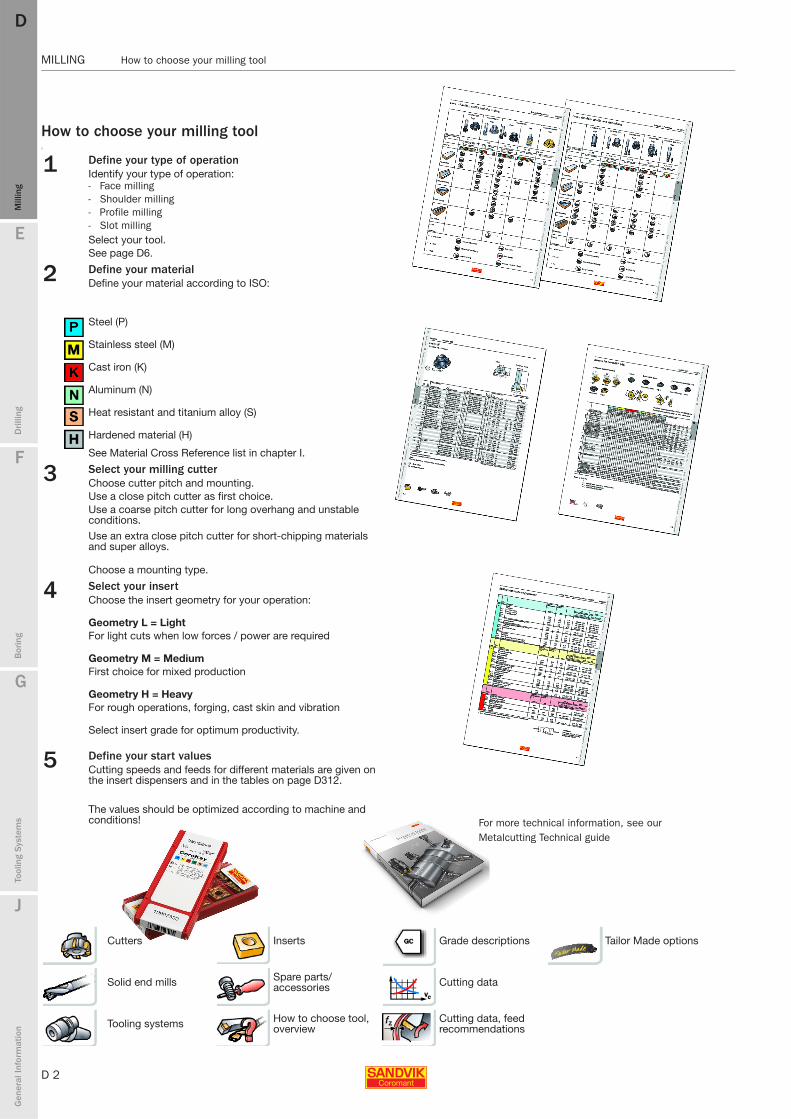
1 Define your type of operationIdentify your type of operation:- Face milling - Shoulder milling - Profile milling- Slot millingSelect your tool.See page D6.
2 Define your materialDefine your material according to ISO:
Steel (P)
Stainless steel (M)
Cast iron (K)
Aluminum (N)
Heat resistant and titanium alloy (S)
Hardened material (H)
See Material Cross Reference list in chapter I.
3 Select your milling cutterChoose cutter pitch and mounting.Use a close pitch cutter as first choice.Use a coarse pitch cutter for long overhang and unstable conditions.
Use an extra close pitch cutter for short-chipping materials and super alloys.
Choose a mounting type.
4 Select your insert Choose the insert geometry for your operation:
Geometry L = LightFor light cuts when low forces / power are required
Geometry M = MediumFirst choice for mixed production
Geometry H = HeavyFor rough operations, forging, cast skin and vibration
Select insert grade for optimum productivity.
5 Define your start valuesCutting speeds and feeds for different materials are given on the insert dispensers and in the tables on page D312.
The values should be optimized according to machine and conditions!
Cutters Inserts Grade descriptions Tailor Made options
Solid end mills Spare parts/accessories Cutting data
Tooling systems How to choose tool, overview
Cutting data, feed recommendations

E
D 3
Mill
ing
Drilli
ng
F
Bor
ing
G
Tool
ing
Syst
ems
J
Gen
eral
Info
rmat
ion
DD
Mill
ing
Content MILLING
D 3
MILLING Content
MILLINGApplicationsFace and shoulder milling D4
Profile milling D5Slot milling D5
ProductsTool overview D6
Insert overview D13
90° shoulder millCoroMill® 490, small cutting depth D16
CoroMill® 390, deep and shallow shoulder milling D24CoroMill® 290, roughing D46
CoroMill® Century, high speed machining D50CoroMill® 790, cutter for non-ferrous material D59
CoroMill® 690, long edge D65Sandvik AUTO-FS - finishing D293
CoroMill® 331, multi-purpose side and facemill D138CoroMill 329, side and face mill D167
75° - 45° face millSandvik AUTO-AF - finishing D289
CoroMill® 365, roughing of cast iron and steel D96CoroMill 360, heavy duty face mill D103
CoroMill 345, face milling D81CoroMill® 245, light cutting D88Sandvik AUTO – Roughing D286
T-Max 45, heavy duty face mill D278
10° face and plunge cutterCoroMill® 210, high productive roughing D72
Profiling milling cuttersCoroMill® 300, light cutting semi finishing D108
CoroMill® 200, roughing D120CoroMill® Ball Nose, semi finishing end mill D126
CoroMill® Ball Nose Finishing, high finishing end mill D133
Internal grooving and threading cutterCoroMill® 327, from 10 mm hole D179CoroMill® 328, from 39 mm hole D174
CoroMill 325, thread whirling cutter D189
Solid carbide end millsCoroMill 326, threading and chamfering D194
CoroMill® Plura, finishing to roughing D214CoroMill® Plura, thread milling D273
Other cuttersCoroMill® 316 – exchangeable heads with EH interface D202
CoroMill 170, gear cutter D196Coromant Plunge Cutter D78
Coromant Finishing Long Edge Cutter D70U-Max® drilling end mill D281
U-Max® chamfering end mill D283AUTO cylinder boring cutter D296
T-MAX Q-cutter D171
ISO inserts D300Torque wrench D304
Cutting data D306
Grade information D334
D 4
MILLING Introduction
E
Mill
ing
Drilli
ng
F
Bor
ing
G
Tool
ing
Syst
ems
J
Gen
eral
Info
rmat
ion
DDM
illin
g
MILLING Introduction
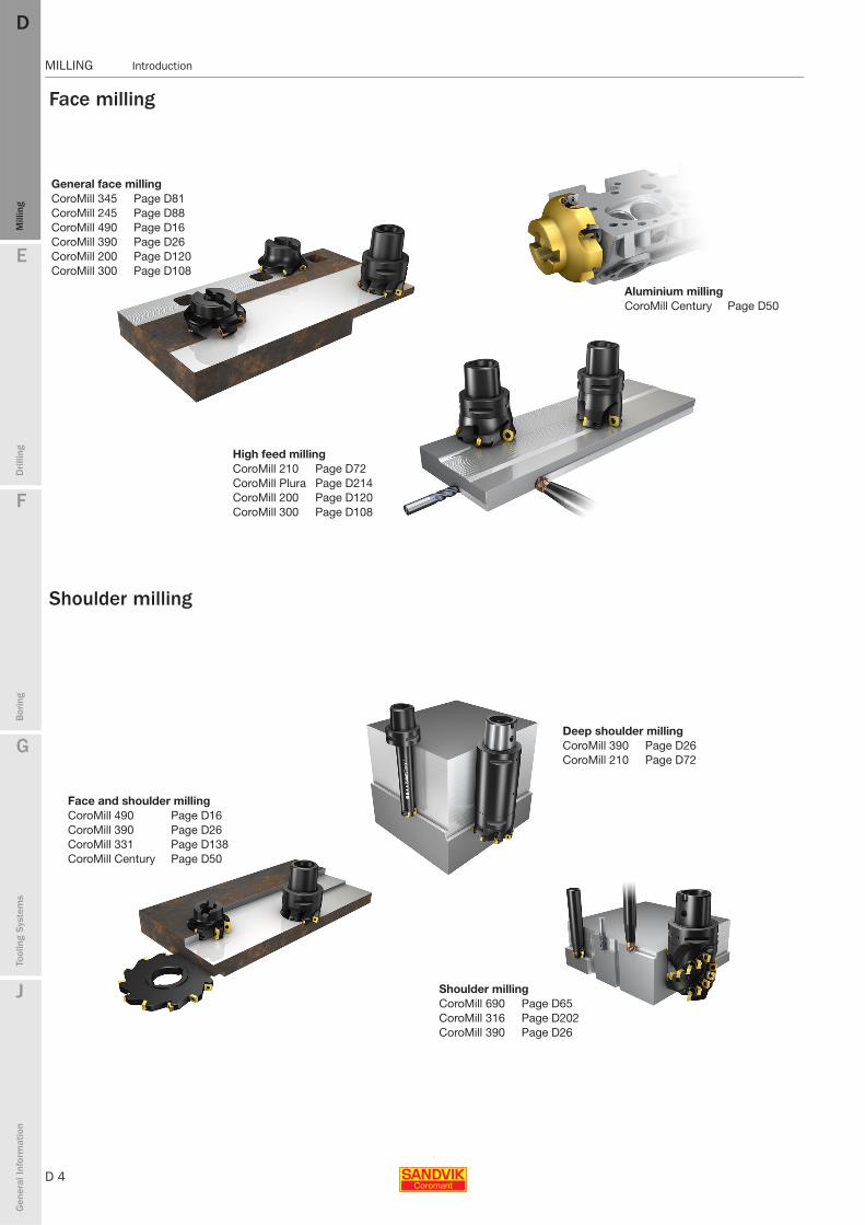
Face milling
Shoulder milling
High feed millingCoroMill 210 Page D72CoroMill Plura Page D214CoroMill 200 Page D120CoroMill 300 Page D108
Aluminium millingCoroMill Century Page D50
General face milling CoroMill 345 Page D81CoroMill 245 Page D88CoroMill 490 Page D16CoroMill 390 Page D26CoroMill 200 Page D120CoroMill 300 Page D108
Face and shoulder millingCoroMill 490 Page D16CoroMill 390 Page D26CoroMill 331 Page D138CoroMill Century Page D50
Deep shoulder millingCoroMill 390 Page D26CoroMill 210 Page D72
Shoulder milling CoroMill 690 Page D65CoroMill 316 Page D202CoroMill 390 Page D26

E
D 5
Mill
ing
Drilli
ng
F
Bor
ing
G
Tool
ing
Syst
ems
J
Gen
eral
Info
rmat
ion
DD
Mill
ing
Introduction MILLING
MILLING Introduction
Profile milling
Slot− and thread milling
FinishingCoroMill Ball Nose finishing Page D133CoroMill 316 Page D202CoroMill Plura Page D214
Roughing/semi - finishingCoroMill 200 Page D120CoroMill 300 Page D108CoroMill 316 Page D202CoroMill Plura Page D214
Roughing/semi - finishingCoroMill 200 Page D120CoroMill 300 Page D108CoroMill 316 Page D202CoroMill Plura Page D214CoroMill Ball nose Page D126
Slot millingCoroMill 390 Page D26CoroMill 690 Page D65CoroMill 316 Page D202CoroMill Plura Page D214
Thread millingCoroMill 328 Page D174CoroMill 327 Page D179CoroMill 326 Page D194CoroMill 316 Page D202CoroMill Plura Page D273
Side and face millingCoroMill 331 Page D138CoroMill 329 Page D167CoroMill 328 Page D174CoroMill 327 Page D179CoroMill 326 Page D194T-MAX Q-Cutter Page D171
D 6
MILLING Tool guide and selection
E
Mill
ing
Drilli
ng
F
Bor
ing
G
Tool
ing
Syst
ems
J
Gen
eral
Info
rmat
ion
DDM
illin
g
MILLING Tool guide and selection
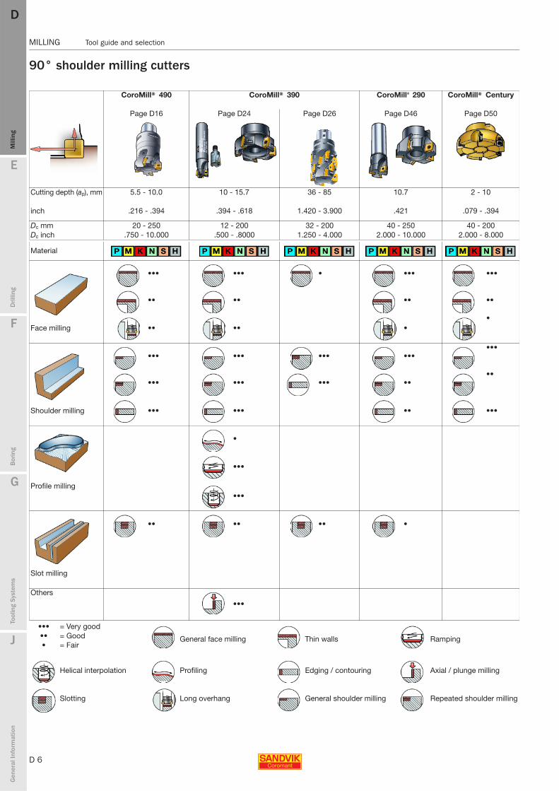
90° shoulder milling cutters
CoroMill® 490 CoroMill® 390 CoroMill® 290 CoroMill® Century
Page D16 Page D24 Page D26 Page D46 Page D50
Cutting depth (ap), mm 5.5 - 10.0 10 - 15.7 36 - 85 10.7 2 - 10
inch .216 - .394 .394 - .618 1.420 - 3.900 .421 .079 - .394
Dc mm 20 - 250 12 - 200 32 - 200 40 - 250 40 - 200Dc inch .750 - 10.000 .500 - .8000 1.250 - 4.000 2.000 - 10.000 2.000 - 8.000
Material
••• ••• • ••• •••
•• •• •• ••
Face milling •• •• ••
••• ••• ••• ••••••
••• ••• ••• ••••
Shoulder milling ••• ••• •• •••
•
•••
Profile milling•••
•• •• •• •
Slot milling
Others
•••
••• = Very good
General face milling Thin walls Ramping•• = Good • = Fair
Helical interpolation Profiling Edging / contouring Axial / plunge milling
Slotting Long overhang General shoulder milling Repeated shoulder milling
E
D 7
Mill
ing
Drilli
ng
F
Bor
ing
G
Tool
ing
Syst
ems
J
Gen
eral
Info
rmat
ion
DD
Mill
ing
Tool guide and selection MILLING
MILLING Tool guide and selection
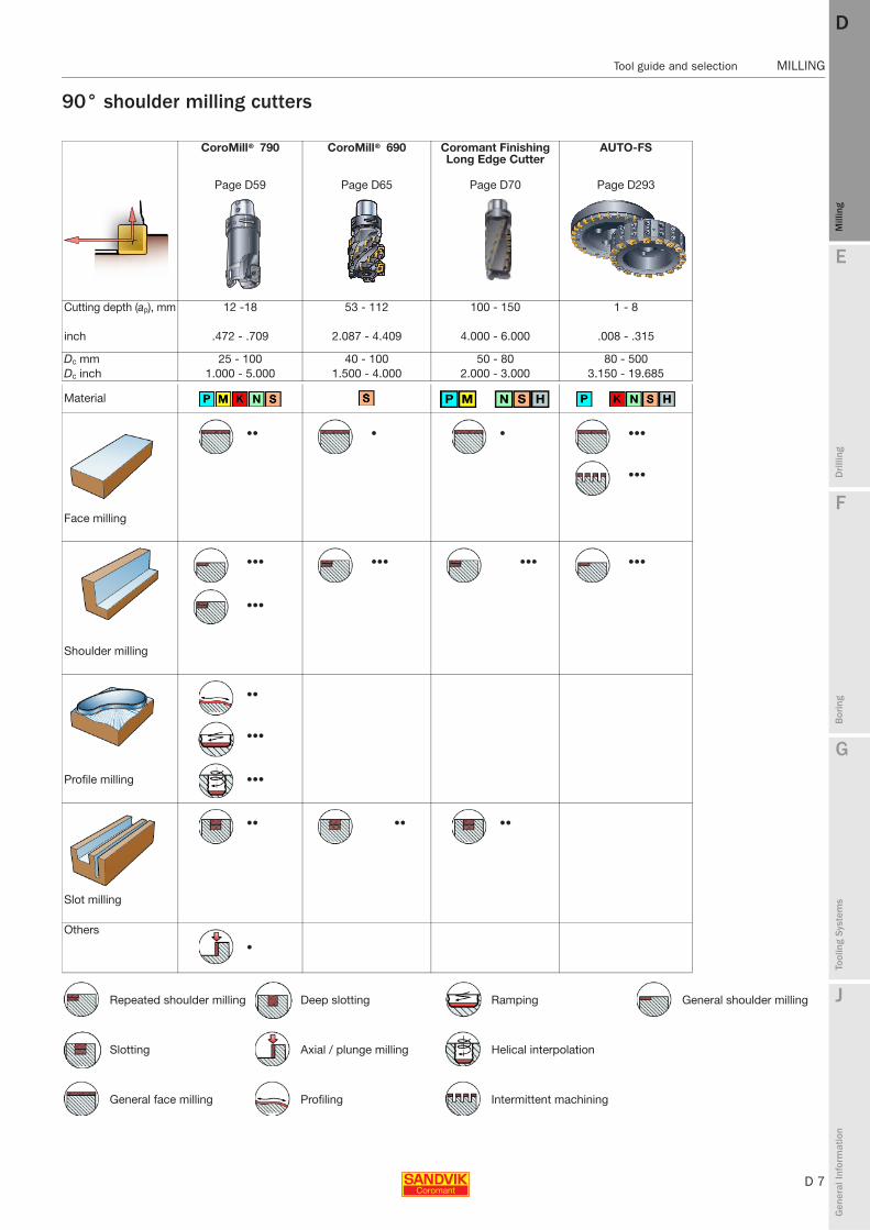
90° shoulder milling cutters
CoroMill® 790 CoroMill® 690 Coromant Finishing Long Edge Cutter
AUTO-FS
Page D59 Page D65 Page D70 Page D293
Cutting depth (ap), mm 12 -18 53 - 112 100 - 150 1 - 8
inch .472 - .709 2.087 - 4.409 4.000 - 6.000 .008 - .315
Dc mm 25 - 100 40 - 100 50 - 80 80 - 500Dc inch 1.000 - 5.000 1.500 - 4.000 2.000 - 3.000 3.150 - 19.685
Material
•• • • •••
•••
Face milling
••• ••• ••• •••
•••
Shoulder milling
••
•••
Profile milling •••
•• •• ••
Slot milling
Others
•
Repeated shoulder milling Deep slotting Ramping General shoulder milling
Slotting Axial / plunge milling Helical interpolation
General face milling Profiling Intermittent machining

D 8
MILLING Tool guide and selection
E
Mill
ing
Drilli
ng
F
Bor
ing
G
Tool
ing
Syst
ems
J
Gen
eral
Info
rmat
ion
DDM
illin
g
MILLING Tool guide and selection
10°-75° face and plunge miling cutters
CoroMill® 210 CoroMill® 345 CoroMill® 245 CoroMill® 360
Page D72 Page D81 Page D88 Page D103
Cutting depth (ap), mm 1.2 - 2 6 6 - 10 13 / 18
inch .047 - .079 .236 .240 - .394 .512 / .709
Dc mm 25 - 160 40 - 250 32 - 250 160 - 500Dc inch 1.000 - 6.000 1.500-10.000 1.250 - 10.000 6.000 - 20.000
Material
••• ••• ••• •••
••• ••• ••• •••
Face milling ••• ••• •• •••
•• •• ••
Shoulder milling
• • •
•• •• ••
Profile milling ••• ••• •••
• • •
Slot milling
Others•• •• ••
Continued ...
••• = Very good
General face milling Ramping Intermittent machining•• = Good • = Fair
Helical interpolation Profiling Axial / plunge milling
Slotting Long overhang Repeated shoulder milling

E
D 9
Mill
ing
Drilli
ng
F
Bor
ing
G
Tool
ing
Syst
ems
J
Gen
eral
Info
rmat
ion
DD
Mill
ing
Tool guide and selection MILLING
MILLING Tool guide and selection
10°-75° face and plunge miling cutters
CoroMill® 365 T-MAX 45 AUTO-R AUTO-AF
Page D96 Page D278 Page D286 Page D289
Cutting depth (ap), mm 6 12 6 1 - 8
inch .236 .472 .236 .008 - .315
Dc mm 40 - 250 100 - 400 125 - 500 80 - 500Dc inch 2.000 - 10.000 3.937 - 15.748 4.921 - 19.685 3.150 - 19.685
Material
••••• •• •••
••••• •• •••
Face milling
•••
Shoulder milling
Profile milling
Slot milling
Others
••• = Very good General face milling •• = Good
• = Fair
Intermittent machining
General shoulder milling

D 10
MILLING Tool guide and selection
E
Mill
ing
Drilli
ng
F
Bor
ing
G
Tool
ing
Syst
ems
J
Gen
eral
Info
rmat
ion
DDM
illin
g
MILLING Tool guide and selection
Round insert and Ball Nose cutters
CoroMill® 200 CoroMill® 300 CoroMill® Ball Nose CoroMill® Ball Nose Finishing
Page D120 Page D108 Page D126
Page D133
Cutting depth (ap), mm 5 - 10 0.7 - 10 8.6 - 44.6 1.2 - 4.8
inch .187 - .375 .027 - .500 .310 - 1.791 .047 - .188
Dc mm 25 - 160 25 - 200 10 - 50 8 - 32Dc inch 1.000 - 10.000 1.000 - 8.000 .375 - 2.000 .312 - 1.250
Material
•• ••
••• •••
Face milling •• ••
• •
Shoulder milling
•• ••• ••• •••
••• ••• ••• •
Profile milling ••• ••• ••• •
• •• • •
Slot milling
Others
• • • •
••• = Very good
General face milling Ramping Intermittent machining•• = Good • = Fair
Helical interpolation Profiling Axial / plunge milling
Slotting Long overhang Repeated shoulder milling

E
D 11
Mill
ing
Drilli
ng
F
Bor
ing
G
Tool
ing
Syst
ems
J
Gen
eral
Info
rmat
ion
DD
Mill
ing
Tool guide and selection MILLING
MILLING Tool guide and selection
Slot, groove, side/face and thread milling cutters
CoroMill® 331 CoroMill® 329 CoroMill® 327 CoroMill® 328 T-MAX® Q-cutter
Page D138 Page D138 Page D167 Page D179 Page D174 Page D171Adjustable Fixed pockets
Cutting depth (ap), mm 6 - 33.8 6 - 10 15 / 18 1.5 - 6.5 1.3 - 5.15 2 - 6inch .236 - 1.643 .250 - .500 .591 / .709 .059 - .256 .051 - .203 .084 - .243
Dc mm 80 - 315 40 - 125 100 - 160 9.7 - 21.7 39 - 80 80 - 315Dc inch 3.150 - 12.000 1.500 - 3.000 4.000 - 5.000 .382 - 1.091 1.535 - 2.480 3.000 - 12.000
Material
•• ••
•• ••
Face milling ••• •••
•• ••
••• •••
Shoulder milling
••• ••• ••• ••• ••• •••
••• ••• ••• ••• •••
Slot milling
Others•• •• ••• •••
••• •••
••• •••
Continued ...
••• = Very good
General face milling Ramping Deep shoulder milling•• = Good • = Fair
Helical interpolation Back shoulder milling Axial / plunge milling Threading outside
Slotting Deep slotting Thin walls Threading inside
Chamfering
D 12
MILLING Tool guide and selection
E
Mill
ing
Drilli
ng
F
Bor
ing
G
Tool
ing
Syst
ems
J
Gen
eral
Info
rmat
ion
DDM
illin
g
MILLING Tool guide and selection
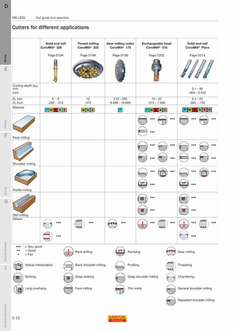
Cutters for different applications
Solid end mill Thread milling Gear milling cutter Exchangeable head Solid end millCoroMill® 326 CoroMill® 325 CoroMill® 170 CoroMill® 316 CoroMill® Plura
Page D194 Page D189 Page D196 Page D202 Page D214
Cutting depth (ap), mm 0.1 - 90inch .004 - 3.543
Dc mm 6 - 8 12 210 - 500 10 - 25 0.4 - 25Dc inch .236 - .315 .472 8.268 - 19.685 .375 - 1.000 .062 - .750
Material
••• ••• ••• •••
•••
Face milling
••• ••• ••• •••
••• ••• ••• •••
Shoulder milling
••• ••• ••• •••
••• •••
Profile milling
••• •••
••• •••
Slot millingOthers
••• ••• ••• ••• ••• ••• •••
••• •••
••• = Very good
Peck drilling Ramping Gear milling•• = Good • = Fair
Helical interpolation Back shoulder milling Profiling Threading
Slotting Deep slotting Deep shoulder milling Chamfering
Long overhang Face milling Thin walls General shoulder milling
Repeated shoulder milling
E
D 13
Mill
ing
Drilli
ng
F
Bor
ing
G
Tool
ing
Syst
ems
J
Gen
eral
Info
rmat
ion
DD
Mill
ing
Inserts overview MILLING
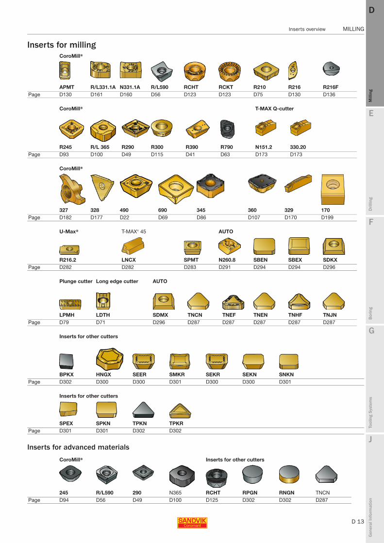
MILLING Inserts overview
Inserts for milling
Inserts for advanced materials
CoroMill®
APMT R/L331.1A N331.1A R/L590 RCHT RCKT R210 R216 R216FPage D130 D161 D160 D56 D123 D123 D75 D130 D136
CoroMill® T-MAX Q-cutter
R245 R/L 365 R290 R300 R390 R790 N151.2 330.20Page D93 D100 D49 D115 D41 D63 D173 D173
CoroMill®
327 328 490 690 345 360 329 170Page D182 D177 D22 D69 D86 D107 D170 D199
U-Max® T-MAX® 45 AUTO
R216.2 LNCX SPMT N260.8 SBEN SBEX SDKXPage D282 D282 D283 D291 D294 D294 D296
Plunge cutter Long edge cutter AUTO
LPMH LDTH SDMX TNCN TNEF TNEN TNHF TNJNPage D79 D71 D296 D287 D287 D287 D287 D287
Inserts for other cutters
BPKX HNGX SEER SMKR SEKR SEKN SNKNPage D302 D300 D300 D301 D300 D300 D301
Inserts for other cutters
SPEX SPKN TPKN TPKRPage D301 D301 D302 D302
CoroMill® Inserts for other cutters
245 R/L590 290 N365 RCHT RPGN RNGN TNCNPage D94 D56 D49 D100 D125 D302 D302 D287
D 14
MILLING Inserts overview
E
Mill
ing
Drilli
ng
F
Bor
ing
G
Tool
ing
Syst
ems
J
Gen
eral
Info
rmat
ion
DDM
illin
g
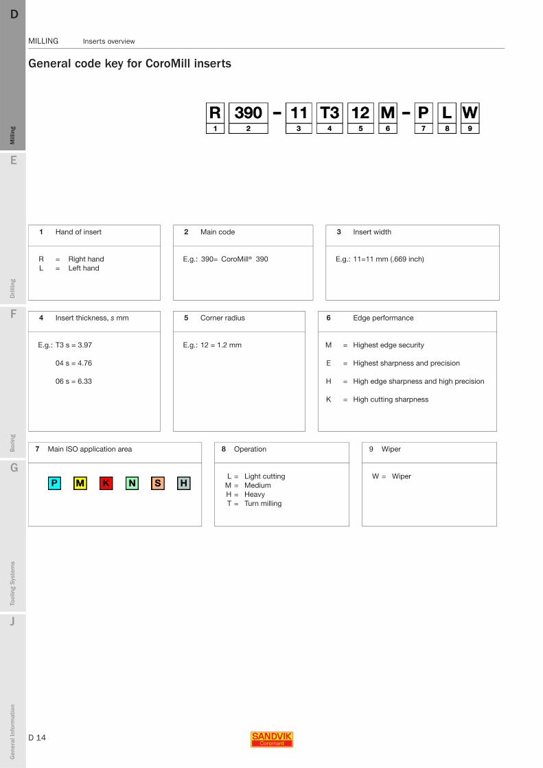
MILLING Inserts overview
General code key for CoroMill inserts
1 Hand of insert 2 Main code 3 Insert width
R = Right hand E.g.: 390= CoroMill® 390 E.g.: 11=11 mm (.669 inch)L = Left hand
4 Insert thickness, s mm 5 Corner radius 6 Edge performance
E.g.: T3 s = 3.97 E.g.: 12 = 1.2 mm M = Highest edge security
04 s = 4.76 E = Highest sharpness and precision
06 s = 6.33 H = High edge sharpness and high precision
K = High cutting sharpness
7 Main ISO application area 8 Operation 9 Wiper
L = Light cutting W = Wiper M = MediumH = HeavyT = Turn milling
E
D 15
Mill
ing
Drilli
ng
F
Bor
ing
G
Tool
ing
Syst
ems
J
Gen
eral
Info
rmat
ion
DD
Mill
ing
Inserts overview MILLING
MILLING Inserts overview
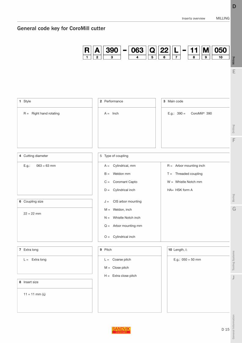
General code key for CoroMill cutter
1 Style 2 Performance 3 Main code
R = Right hand rotating A = Inch E.g.: 390 = CoroMill® 390
4 Cutting diameter 5 Type of coupling
E.g.: 063 = 63 mm A = Cylindrical, mm R = Arbor mounting inch
B = Weldon mm T = Threaded coupling
C = Coromant Capto W = Whistle Notch mm
D = Cylindrical inch HA= HSK form A
6 Coupling size J = CIS arbor mounting
M = Weldon, inch22 = 22 mm
N = Whistle Notch inch
Q = Arbor mounting mm
O = Cylindrical inch
7 Extra long 9 Pitch 10 Length, l1
L = Extra long L = Coarse pitch E.g.: 050 = 50 mm
M = Close pitch
H = Extra close pitch
8 Insert size
11 = 11 mm (la)
D 16
MILLING CoroMill® 490
E
Mill
ing
Drilli
ng
F
Bor
ing
G
Tool
ing
Syst
ems
J
Gen
eral
Info
rmat
ion
DDM
illin
g
MILLING CoroMill® 490
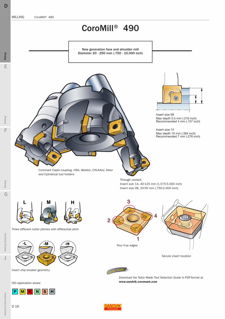
CoroMill® 490
New generation face and shoulder millDiameter 20 - 250 mm (.750 - 10.000 inch)
Through coolant:Insert size 14, 40-125 mm (1.575-5.000 inch)Insert size 08, 20-50 mm (.750-2.000 inch)
Insert chip breaker geometry
Three different cutter pitches with differential pitch
ISO application areas:
Four true edges
Secure insert location
Download the Tailor Made Tool Selection Guide in PDF-format at www.sandvik.coromant.com
Coromant Capto coupling, HSK, Weldon, CIS-Arbor, Arbor and Cylindrical tool holders
Insert size 08Max depth 5.5 mm (.216 inch)Recommended 4 mm (.157 inch)
Insert size 14Max depth 10 mm (.394 inch)Recommended 7 mm (.276 inch)
E
D 17
Mill
ing
Drilli
ng
F
Bor
ing
G
Tool
ing
Syst
ems
J
Gen
eral
Info
rmat
ion
DD
Mill
ing
CoroMill® 490 MILLING
MILLING CoroMill® 490
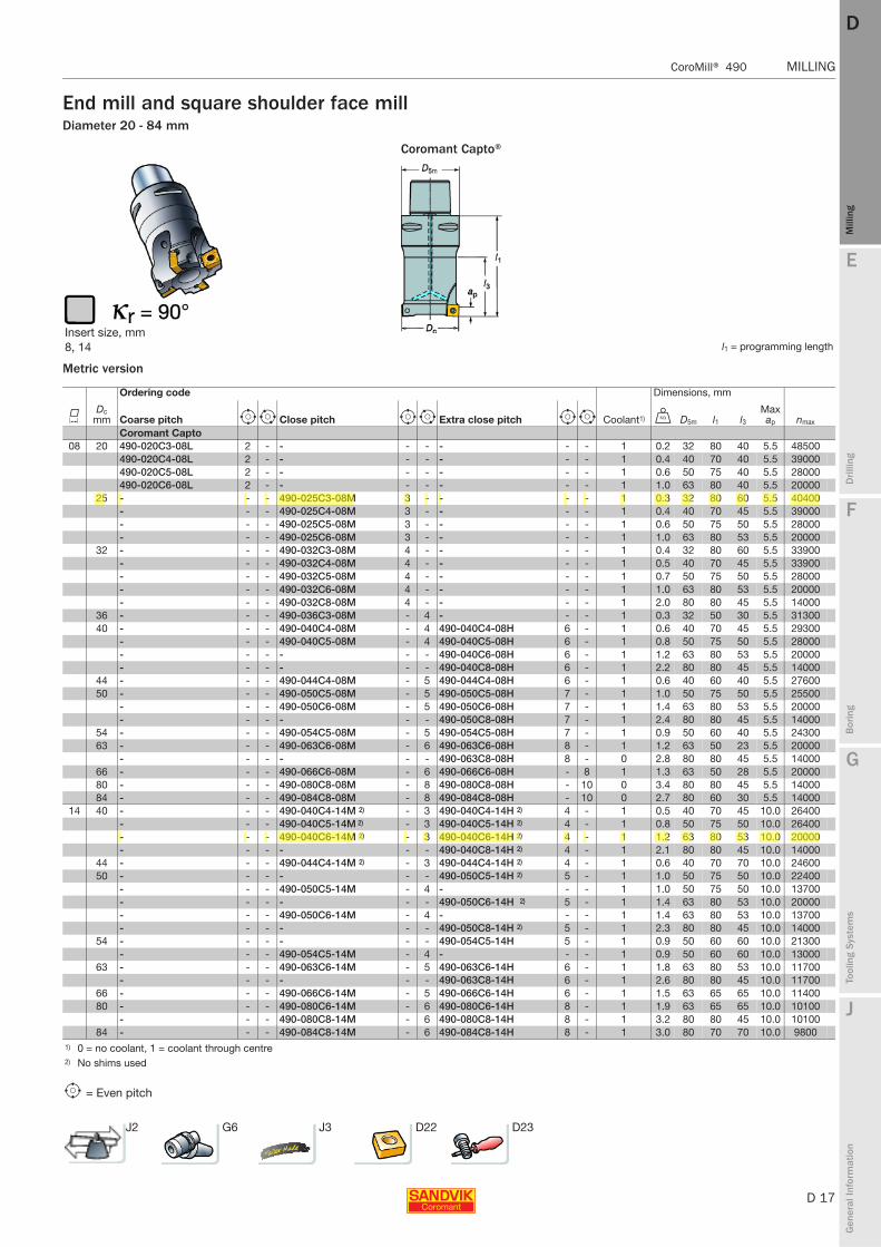
End mill and square shoulder face millDiameter 20 - 84 mm
Metric version
Coromant Capto®
Insert size, mm8, 14 l1 = programming length
Ordering code Dimensions, mm
KDc
mm Coarse pitch e i Close pitch e i Extra close pitch e i Coolant1) U D5m l1 l3Max ap nmax
Coromant Capto 08 20 490-020C3-08L 2 - - - - - - - 1 0.2 32 80 40 5.5 48500
490-020C4-08L 2 - - - - - - - 1 0.4 40 70 40 5.5 39000490-020C5-08L 2 - - - - - - - 1 0.6 50 75 40 5.5 28000490-020C6-08L 2 - - - - - - - 1 1.0 63 80 40 5.5 20000
25 - - - 490-025C3-08M 3 - - - - 1 0.3 32 80 60 5.5 40400- - - 490-025C4-08M 3 - - - - 1 0.4 40 70 45 5.5 39000- - - 490-025C5-08M 3 - - - - 1 0.6 50 75 50 5.5 28000- - - 490-025C6-08M 3 - - - - 1 1.0 63 80 53 5.5 20000
32 - - - 490-032C3-08M 4 - - - - 1 0.4 32 80 60 5.5 33900- - - 490-032C4-08M 4 - - - - 1 0.5 40 70 45 5.5 33900- - - 490-032C5-08M 4 - - - - 1 0.7 50 75 50 5.5 28000- - - 490-032C6-08M 4 - - - - 1 1.0 63 80 53 5.5 20000- - - 490-032C8-08M 4 - - - - 1 2.0 80 80 45 5.5 14000
36 - - - 490-036C3-08M - 4 - - - 1 0.3 32 50 30 5.5 3130040 - - - 490-040C4-08M - 4 490-040C4-08H 6 - 1 0.6 40 70 45 5.5 29300
- - - 490-040C5-08M - 4 490-040C5-08H 6 - 1 0.8 50 75 50 5.5 28000- - - - - - 490-040C6-08H 6 - 1 1.2 63 80 53 5.5 20000- - - - - - 490-040C8-08H 6 - 1 2.2 80 80 45 5.5 14000
44 - - - 490-044C4-08M - 5 490-044C4-08H 6 - 1 0.6 40 60 40 5.5 2760050 - - - 490-050C5-08M - 5 490-050C5-08H 7 - 1 1.0 50 75 50 5.5 25500
- - - 490-050C6-08M - 5 490-050C6-08H 7 - 1 1.4 63 80 53 5.5 20000- - - - - - 490-050C8-08H 7 - 1 2.4 80 80 45 5.5 14000
54 - - - 490-054C5-08M - 5 490-054C5-08H 7 - 1 0.9 50 60 40 5.5 2430063 - - - 490-063C6-08M - 6 490-063C6-08H 8 - 1 1.2 63 50 23 5.5 20000
- - - - - - 490-063C8-08H 8 - 0 2.8 80 80 45 5.5 1400066 - - - 490-066C6-08M - 6 490-066C6-08H - 8 1 1.3 63 50 28 5.5 2000080 - - - 490-080C8-08M - 8 490-080C8-08H - 10 0 3.4 80 80 45 5.5 1400084 - - - 490-084C8-08M - 8 490-084C8-08H - 10 0 2.7 80 60 30 5.5 14000
14 40 - - - 490-040C4-14M 2) - 3 490-040C4-14H 2) 4 - 1 0.5 40 70 45 10.0 26400- - - 490-040C5-14M 2) - 3 490-040C5-14H 2) 4 - 1 0.8 50 75 50 10.0 26400- - - 490-040C6-14M 2) - 3 490-040C6-14H 2) 4 - 1 1.2 63 80 53 10.0 20000- - - - - - 490-040C8-14H 2) 4 - 1 2.1 80 80 45 10.0 14000
44 - - - 490-044C4-14M 2) - 3 490-044C4-14H 2) 4 - 1 0.6 40 70 70 10.0 2460050 - - - - - - 490-050C5-14H 2) 5 - 1 1.0 50 75 50 10.0 22400
- - - 490-050C5-14M - 4 - - - 1 1.0 50 75 50 10.0 13700- - - - - - 490-050C6-14H 2) 5 - 1 1.4 63 80 53 10.0 20000- - - 490-050C6-14M - 4 - - - 1 1.4 63 80 53 10.0 13700- - - - - - 490-050C8-14H 2) 5 - 1 2.3 80 80 45 10.0 14000
54 - - - - - - 490-054C5-14H 5 - 1 0.9 50 60 60 10.0 21300- - - 490-054C5-14M - 4 - - - 1 0.9 50 60 60 10.0 13000
63 - - - 490-063C6-14M - 5 490-063C6-14H 6 - 1 1.8 63 80 53 10.0 11700- - - - - - 490-063C8-14H 6 - 1 2.6 80 80 45 10.0 11700
66 - - - 490-066C6-14M - 5 490-066C6-14H 6 - 1 1.5 63 65 65 10.0 1140080 - - - 490-080C6-14M - 6 490-080C6-14H 8 - 1 1.9 63 65 65 10.0 10100
- - - 490-080C8-14M - 6 490-080C8-14H 8 - 1 3.2 80 80 45 10.0 1010084 - - - 490-084C8-14M - 6 490-084C8-14H 8 - 1 3.0 80 70 70 10.0 9800
1) 0 = no coolant, 1 = coolant through centre2) No shims used
e = Even pitch
J2 G6 J3 D22 D23
D 18
MILLING CoroMill® 490
E
Mill
ing
Drilli
ng
F
Bor
ing
G
Tool
ing
Syst
ems
J
Gen
eral
Info
rmat
ion
DDM
illin
g
MILLING CoroMill® 490
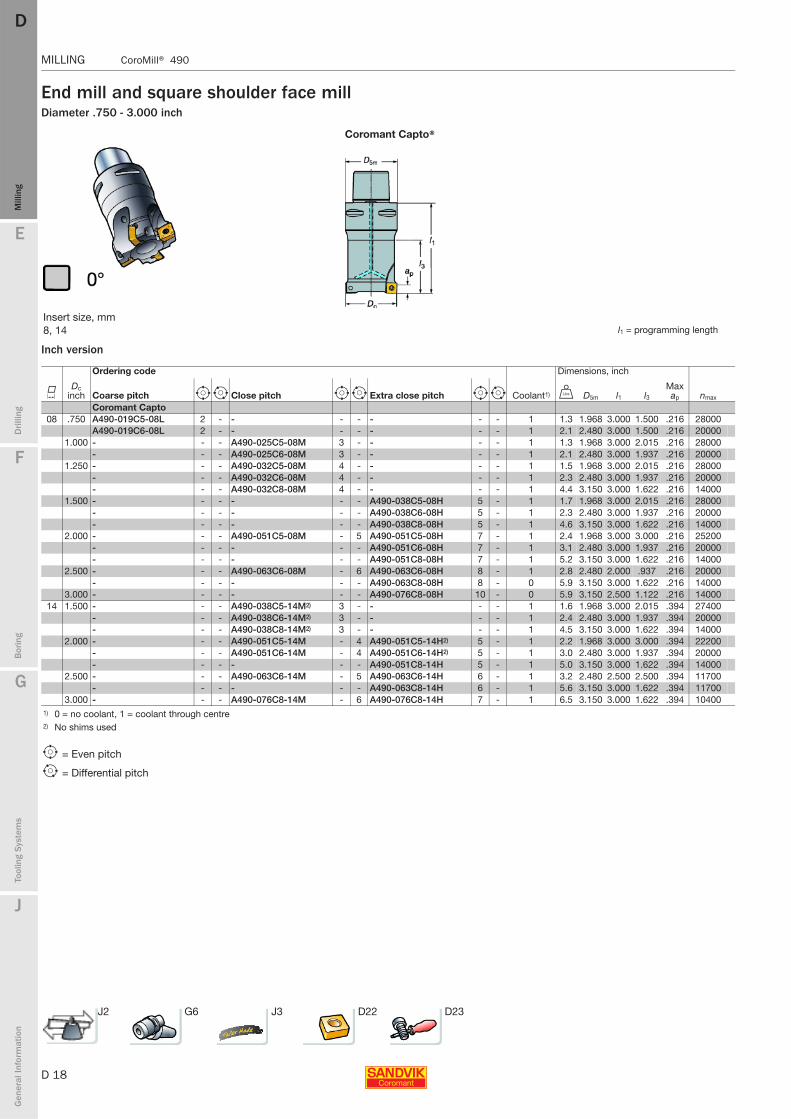
End mill and square shoulder face millDiameter .750 - 3.000 inch
Inch version
Coromant Capto®
Insert size, mm8, 14 l1 = programming length
Ordering code Dimensions, inch
KDc
inch Coarse pitch e i Close pitch e i Extra close pitch e i Coolant1) V D5m l1 l3Max ap nmax
Coromant Capto 08 .750 A490-019C5-08L 2 - - - - - - - 1 1.3 1.968 3.000 1.500 .216 28000
A490-019C6-08L 2 - - - - - - - 1 2.1 2.480 3.000 1.500 .216 200001.000 - - - A490-025C5-08M 3 - - - - 1 1.3 1.968 3.000 2.015 .216 28000
- - - A490-025C6-08M 3 - - - - 1 2.1 2.480 3.000 1.937 .216 200001.250 - - - A490-032C5-08M 4 - - - - 1 1.5 1.968 3.000 2.015 .216 28000
- - - A490-032C6-08M 4 - - - - 1 2.3 2.480 3.000 1.937 .216 20000- - - A490-032C8-08M 4 - - - - 1 4.4 3.150 3.000 1.622 .216 14000
1.500 - - - - - - A490-038C5-08H 5 - 1 1.7 1.968 3.000 2.015 .216 28000- - - - - - A490-038C6-08H 5 - 1 2.3 2.480 3.000 1.937 .216 20000- - - - - - A490-038C8-08H 5 - 1 4.6 3.150 3.000 1.622 .216 14000
2.000 - - - A490-051C5-08M - 5 A490-051C5-08H 7 - 1 2.4 1.968 3.000 3.000 .216 25200- - - - - - A490-051C6-08H 7 - 1 3.1 2.480 3.000 1.937 .216 20000- - - - - - A490-051C8-08H 7 - 1 5.2 3.150 3.000 1.622 .216 14000
2.500 - - - A490-063C6-08M - 6 A490-063C6-08H 8 - 1 2.8 2.480 2.000 .937 .216 20000- - - - - - A490-063C8-08H 8 - 0 5.9 3.150 3.000 1.622 .216 14000
3.000 - - - - - - A490-076C8-08H 10 - 0 5.9 3.150 2.500 1.122 .216 1400014 1.500 - - - A490-038C5-14M2) 3 - - - - 1 1.6 1.968 3.000 2.015 .394 27400
- - - A490-038C6-14M2) 3 - - - - 1 2.4 2.480 3.000 1.937 .394 20000- - - A490-038C8-14M2) 3 - - - - 1 4.5 3.150 3.000 1.622 .394 14000
2.000 - - - A490-051C5-14M - 4 A490-051C5-14H2) 5 - 1 2.2 1.968 3.000 3.000 .394 22200- - - A490-051C6-14M - 4 A490-051C6-14H2) 5 - 1 3.0 2.480 3.000 1.937 .394 20000- - - - - - A490-051C8-14H 5 - 1 5.0 3.150 3.000 1.622 .394 14000
2.500 - - - A490-063C6-14M - 5 A490-063C6-14H 6 - 1 3.2 2.480 2.500 2.500 .394 11700- - - - - - A490-063C8-14H 6 - 1 5.6 3.150 3.000 1.622 .394 11700
3.000 - - - A490-076C8-14M - 6 A490-076C8-14H 7 - 1 6.5 3.150 3.000 1.622 .394 104001) 0 = no coolant, 1 = coolant through centre2) No shims used
e = Even pitch
i = Differential pitch
J2 G6 J3 D22 D23
E
D 19
Mill
ing
Drilli
ng
F
Bor
ing
G
Tool
ing
Syst
ems
J
Gen
eral
Info
rmat
ion
DD
Mill
ing
CoroMill® 490 MILLING
MILLING CoroMill® 490
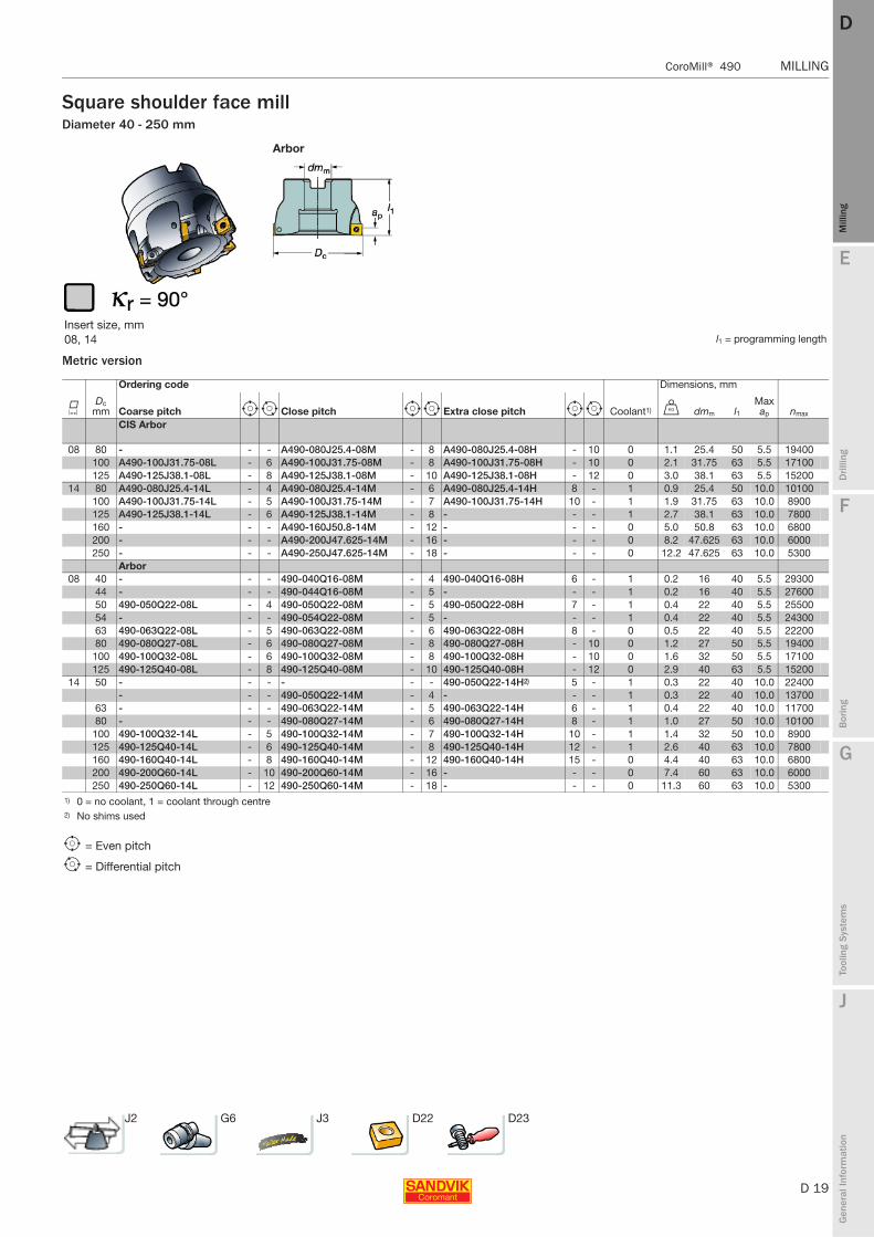
Square shoulder face millDiameter 40 - 250 mm
Metric version
Arbor
Insert size, mm08, 14 l1 = programming length
Ordering code Dimensions, mm
KDc
mm Coarse pitch e i Close pitch e i Extra close pitch e i Coolant1) U dmm l1Max ap nmax
CIS Arbor
08 80 - - - A490-080J25.4-08M - 8 A490-080J25.4-08H - 10 0 1.1 25.4 50 5.5 19400100 A490-100J31.75-08L - 6 A490-100J31.75-08M - 8 A490-100J31.75-08H - 10 0 2.1 31.75 63 5.5 17100125 A490-125J38.1-08L - 8 A490-125J38.1-08M - 10 A490-125J38.1-08H - 12 0 3.0 38.1 63 5.5 15200
14 80 A490-080J25.4-14L - 4 A490-080J25.4-14M - 6 A490-080J25.4-14H 8 - 1 0.9 25.4 50 10.0 10100100 A490-100J31.75-14L - 5 A490-100J31.75-14M - 7 A490-100J31.75-14H 10 - 1 1.9 31.75 63 10.0 8900125 A490-125J38.1-14L - 6 A490-125J38.1-14M - 8 - - - 1 2.7 38.1 63 10.0 7800160 - - - A490-160J50.8-14M - 12 - - - 0 5.0 50.8 63 10.0 6800200 - - - A490-200J47.625-14M - 16 - - - 0 8.2 47.625 63 10.0 6000250 - - - A490-250J47.625-14M - 18 - - - 0 12.2 47.625 63 10.0 5300
Arbor08 40 - - - 490-040Q16-08M - 4 490-040Q16-08H 6 - 1 0.2 16 40 5.5 29300
44 - - - 490-044Q16-08M - 5 - - - 1 0.2 16 40 5.5 2760050 490-050Q22-08L - 4 490-050Q22-08M - 5 490-050Q22-08H 7 - 1 0.4 22 40 5.5 2550054 - - - 490-054Q22-08M - 5 - - - 1 0.4 22 40 5.5 2430063 490-063Q22-08L - 5 490-063Q22-08M - 6 490-063Q22-08H 8 - 0 0.5 22 40 5.5 2220080 490-080Q27-08L - 6 490-080Q27-08M - 8 490-080Q27-08H - 10 0 1.2 27 50 5.5 19400
100 490-100Q32-08L - 6 490-100Q32-08M - 8 490-100Q32-08H - 10 0 1.6 32 50 5.5 17100125 490-125Q40-08L - 8 490-125Q40-08M - 10 490-125Q40-08H - 12 0 2.9 40 63 5.5 15200
14 50 - - - - - - 490-050Q22-14H2) 5 - 1 0.3 22 40 10.0 22400- - - 490-050Q22-14M - 4 - - - 1 0.3 22 40 10.0 13700
63 - - - 490-063Q22-14M - 5 490-063Q22-14H 6 - 1 0.4 22 40 10.0 1170080 - - - 490-080Q27-14M - 6 490-080Q27-14H 8 - 1 1.0 27 50 10.0 10100
100 490-100Q32-14L - 5 490-100Q32-14M - 7 490-100Q32-14H 10 - 1 1.4 32 50 10.0 8900125 490-125Q40-14L - 6 490-125Q40-14M - 8 490-125Q40-14H 12 - 1 2.6 40 63 10.0 7800160 490-160Q40-14L - 8 490-160Q40-14M - 12 490-160Q40-14H 15 - 0 4.4 40 63 10.0 6800200 490-200Q60-14L - 10 490-200Q60-14M - 16 - - - 0 7.4 60 63 10.0 6000250 490-250Q60-14L - 12 490-250Q60-14M - 18 - - - 0 11.3 60 63 10.0 5300
1) 0 = no coolant, 1 = coolant through centre2) No shims used
e = Even pitch
i = Differential pitch
J2 G6 J3 D22 D23
D 20
MILLING CoroMill® 490
E
Mill
ing
Drilli
ng
F
Bor
ing
G
Tool
ing
Syst
ems
J
Gen
eral
Info
rmat
ion
DDM
illin
g
MILLING CoroMill® 490
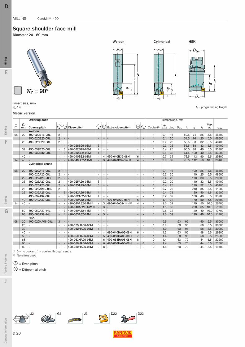
Square shoulder face millDiameter 20 - 80 mm
Metric version
Weldon Cylindrical HSK
Insert size, mm8, 14 l1 = programming length
Ordering code Dimensions, mm
KDc
mm Coarse pitch e i Close pitch e i Extra close pitch e i Coolant1) U dmm D5m l1 l2 l3Max ap nmax
Weldon08 20 490-020B16-08L 2 - - - - - - - 1 0.1 16 50.5 74 25 5.5 48500
490-020B20-08L 2 - - - - - - - 1 0.1 20 51.5 76 25 5.5 4850025 490-025B20-08L 2 - - - - - - - 1 0.2 20 58.5 83 32 5.5 40400
- - - 490-025B25-08M 3 - - - - 1 0.3 25 56.5 88 32 5.5 4040032 490-032B25-08L - 3 490-032B25-08M 4 - - - - 1 0.4 25 66.5 98 40 5.5 33900
490-032B32-08L - 3 490-032B32-08M 4 - - - - 1 0.5 32 64.5 100 40 5.5 3390040 - - - 490-040B32-08M - 4 490-040B32-08H 6 - 1 0.7 32 76.5 112 50 5.5 29300
14 40 - - - 490-040B32-14M2) - 3 490-040B32-14H2) 4 - 1 0.6 32 76.5 112 50 10.0 26400Cylindrical shank
08 20 490-020A16-08L 2 - - - - - - - 1 0.1 16 100 25 5.5 48500490-020A20-08L 2 - - - - - - - 1 0.2 20 110 25 5.5 48500
22 490-022A20L-08L 2 - - - - - - - 1 0.4 20 170 30 5.5 2030025 490-025A20-08L 2 - 490-025A20-08M 3 - - - - 1 0.2 20 110 32 5.5 40400
490-025A25-08L 2 - 490-025A25-08M 3 - - - - 1 0.4 25 120 32 5.5 4040028 490-028A25L-08L 2 - - - - - - - 1 0.7 25 210 35 5.5 1100032 490-032A25-08L - 3 490-032A25-08M 4 - - - - 1 0.4 25 120 40 5.5 33900
490-032A32-08L - 3 490-032A32-08M 4 - - - - 1 0.7 32 130 40 5.5 3390040 490-040A32-08L - 3 490-040A32-08M - 4 490-040A32-08H 6 - 1 1.1 32 170 50 5.5 20300
14 40 - - - 490-040A32-14M 2) - 3 490-040A32-14H 2) 4 - 1 1.0 32 170 50 10.0 26400- - - 490-040A32L-14M 2) - 3 - - - 1 1.5 32 250 65 10.0 7600
50 490-050A32-14L - 3 490-050A32-14M - 4 - - - 1 0.8 32 120 40 10.0 1370063 490-063A32-14L - 4 490-063A32-14M - 5 - - - 1 1.0 32 120 40 10.0 11700
HSK08 20 490-020HA06-08L 2 - - - - - - - 1 0.9 63 95 40 5.5 30000
25 - - - 490-025HA06-08M 3 - - - - 1 0.9 63 95 50 5.5 3000032 - - - 490-032HA06-08M 4 - - - - 1 1.0 63 95 58 5.5 3000040 - - - - - - 490-040HA06-08H 6 - 1 1.2 63 95 58 5.5 2930050 - - - 490-050HA06-08M - 5 490-050HA06-08H 7 - 1 1.4 63 95 58 5.5 2550063 - - - 490-063HA06-08M - 6 490-063HA06-08H 8 - 0 1.4 63 70 44 5.5 2220066 - - - 490-066HA06-08M - 6 490-066HA06-08H - 8 0 1.4 63 70 44 5.5 2160080 - - - 490-080HA06-08M - 8 - - - 0 1.6 63 70 44 5.5 19400
1) 0 = no coolant, 1 = coolant through centre2) No shims used
e = Even pitch
i = Differential pitch
J2 G6 J3 D22 D23
E
D 21
Mill
ing
Drilli
ng
F
Bor
ing
G
Tool
ing
Syst
ems
J
Gen
eral
Info
rmat
ion
DD
Mill
ing
CoroMill® 490 MILLING
MILLING CoroMill® 490
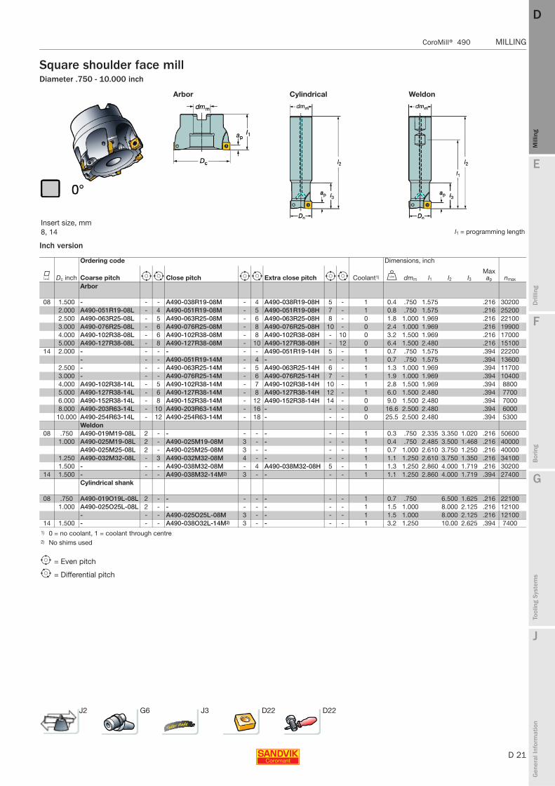
Square shoulder face millDiameter .750 - 10.000 inch
Inch version
Arbor Cylindrical Weldon
Insert size, mm8, 14 l1 = programming length
Ordering code Dimensions, inch
K Dc inch Coarse pitch e i Close pitch e i Extra close pitch e i Coolant1) V dmm l1 l2 l3Max ap nmax
Arbor
08 1.500 - - - A490-038R19-08M - 4 A490-038R19-08H 5 - 1 0.4 .750 1.575 .216 302002.000 A490-051R19-08L - 4 A490-051R19-08M - 5 A490-051R19-08H 7 - 1 0.8 .750 1.575 .216 252002.500 A490-063R25-08L - 5 A490-063R25-08M - 6 A490-063R25-08H 8 - 0 1.8 1.000 1.969 .216 221003.000 A490-076R25-08L - 6 A490-076R25-08M - 8 A490-076R25-08H 10 - 0 2.4 1.000 1.969 .216 199004.000 A490-102R38-08L - 6 A490-102R38-08M - 8 A490-102R38-08H - 10 0 3.2 1.500 1.969 .216 170005.000 A490-127R38-08L - 8 A490-127R38-08M - 10 A490-127R38-08H - 12 0 6.4 1.500 2.480 .216 15100
14 2.000 - - - - - - A490-051R19-14H 5 - 1 0.7 .750 1.575 .394 22200- - - A490-051R19-14M - 4 - - - 1 0.7 .750 1.575 .394 13600
2.500 - - - A490-063R25-14M - 5 A490-063R25-14H 6 - 1 1.3 1.000 1.969 .394 117003.000 - - - A490-076R25-14M - 6 A490-076R25-14H 7 - 1 1.9 1.000 1.969 .394 104004.000 A490-102R38-14L - 5 A490-102R38-14M - 7 A490-102R38-14H 10 - 1 2.8 1.500 1.969 .394 88005.000 A490-127R38-14L - 6 A490-127R38-14M - 8 A490-127R38-14H 12 - 1 6.0 1.500 2.480 .394 77006.000 A490-152R38-14L - 8 A490-152R38-14M - 12 A490-152R38-14H 14 - 0 9.0 1.500 2.480 .394 70008.000 A490-203R63-14L - 10 A490-203R63-14M - 16 - - - 0 16.6 2.500 2.480 .394 6000
10.000 A490-254R63-14L - 12 A490-254R63-14M - 18 - - - 0 25.5 2.500 2.480 .394 5300Weldon
08 .750 A490-019M19-08L 2 - - - - - - - 1 0.3 .750 2.335 3.350 1.020 .216 506001.000 A490-025M19-08L 2 - A490-025M19-08M 3 - - - - 1 0.4 .750 2.485 3.500 1.468 .216 40000
A490-025M25-08L 2 - A490-025M25-08M 3 - - - - 1 0.7 1.000 2.610 3.750 1.250 .216 400001.250 A490-032M32-08L - 3 A490-032M32-08M 4 - - - - 1 1.1 1.250 2.610 3.750 1.350 .216 341001.500 - - - A490-038M32-08M - 4 A490-038M32-08H 5 - 1 1.3 1.250 2.860 4.000 1.719 .216 30200
14 1.500 - - - A490-038M32-14M2) 3 - - - - 1 1.1 1.250 2.860 4.000 1.719 .394 27400Cylindrical shank
08 .750 A490-019O19L-08L 2 - - - - - - - 1 0.7 .750 6.500 1.625 .216 221001.000 A490-025O25L-08L 2 - - - - - - - 1 1.5 1.000 8.000 2.125 .216 12100
- - - A490-025O25L-08M 3 - - - - 1 1.5 1.000 8.000 2.125 .216 1210014 1.500 - - - A490-038O32L-14M2) 3 - - - - 1 3.2 1.250 10.00 2.625 .394 7400
1) 0 = no coolant, 1 = coolant through centre2) No shims used
e = Even pitch
i = Differential pitch
J2 G6 J3 D22 D22
D 22
MILLING CoroMill® 490
E
Mill
ing
Drilli
ng
F
Bor
ing
G
Tool
ing
Syst
ems
J
Gen
eral
Info
rmat
ion
DDM
illin
g
MILLING CoroMill® 490
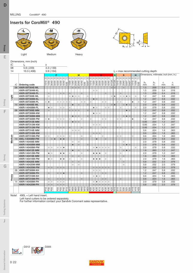
Inserts for CoroMill® 490
Light Medium Heavy
Dimensions, mm (inch)iC la s 08 5.6 (.220) 3.3 (.130)14 10.3 (.406) 3.9 (.154) la = max recommended cutting depth
P M K N S H Dimensions, millimeter, inch (mm, in.)
iC Ordering code
GC GC GC GC GC GC GC CT GC GC GC GC GC CT GC GC GC GC GC GC GC GC - - GC GC GC GC GC GC GC CT
bsmm
bsin.
rεmm
rεin.10
1010
3030
4032
2042
2042
3042
4053
010
3010
4020
3020
4042
4053
0S
30T
1010
1020
3040
3220
4220
4230
4240
H13
AH
13A
1010
1030
2040
S30
TS
40T
1010
1030
530
Lig
ht
08 490R-08T304E-ML ✩ ✩ ✩ ✩ ✩ ✩ 1.5 .059 0.4 .016490R-08T304M-KL ✩ ✩ 1.5 .059 0.4 .016490R-08T304M-PL ✩ ✩ ✩ ✩ ✩ ✩ ✩ 1.5 .059 0.4 .016490R-08T308E-ML ✩ ✩ ★ ✩ ✩ ✩ ✩ ★ ✩ ✩ ★ ✩ ✩ 1.2 .047 0.8 .032490R-08T308M-KL ★ ✩ 1.2 .047 0.8 .032490R-08T308M-PL ✩ ★ ✩ ✩ ✩ ✩ ✩ ✩ ✩ ✩ ✩ ✩ ✩ ✩ ★ ✩ 1.2 .047 0.8 .032
14 490R-140408E-ML ★ ✩ ✩ ✩ ★ ✩ ★ ✩ 2.0 .079 0.8 .032490R-140408M-PL ★ ✩ ✩ ✩ ✩ ★ ✩ ✩ ✩ ✩ ✩ 2.0 .079 0.8 .032
Med
ium
08 490R-08T308E-MM ✩ ✩ ✩ ✩ ✩ ✩ ★ ✩ 1.2 .047 0.8 .032490R-08T308M-KM ★ ✩ ✩ 1.2 .047 0.8 .032490R-08T308M-MM ★ ✩ ✩ ✩ ✩ ★ ✩ 1.2 .047 0.8 .032490R-08T308M-PM ✩ ★ ✩ ✩ ✩ ✩ ✩ ✩ ✩ ✩ ✩ ✩ ★ 1.2 .047 0.8 .032490R-08T312E-MM ★ ✩ ✩ 0.85 .034 1.2 .047490R-08T312M-KM ✩ ✩ ✩ 0.85 .034 1.2 .047490R-08T312M-PM ✩ ✩ ✩ ✩ ✩ ✩ ✩ ✩ ✩ ✩ ✩ ✩ ✩ 0.85 .034 1.2 .047490R-08T316E-MM ✩ ✩ ✩ 0.6 .024 1.6 .063490R-08T316M-KM ✩ ✩ ✩ 0.6 .024 1.6 .063490R-08T316M-PM ✩ ✩ ✩ ✩ ✩ ✩ ✩ ✩ ✩ ✩ ✩ ✩ 0.6 .024 1.6 .063
14 490L-140408M-PM ✩ ★ ★ ★ ✩ ★ ✩ 2.0 .079 0.8 .032490R-140408E-MM ✩ ✩ ✩ 2.0 .079 0.8 .032490R-140408M-MM ★ ✩ ✩ ✩ ★ ✩ 2.0 .079 0.8 .032490R-140408M-PM ✩ ✩ ✩ ✩ ★ ✩ ★ ✩ ✩ ✩ ✩ ✩ ✩ 2.0 .079 0.8 .032490R-140412E-MM ★ ✩ ✩ ✩ ★ ✩ 1.6 .063 1.2 .047490R-140412M-PM ★ ✩ ★ ★ ✩ ✩ ★ ★ ★ ✩ ✩ 2.0 .079 1.2 .047490R-140416E-MM ✩ ✩ ✩ 1.6 .063 1.6 .063490R-140416M-PM ★ ✩ ★ ★ ✩ ✩ ★ ★ ★ ✩ ✩ 2.0 .079 1.6 .063490R-140420E-MM ✩ ✩ ✩ 0.8 .032 2.0 .079490R-140420M-MM ✩ ✩ ✩ 0.8 .032 2.0 .079490R-140420M-PM ✩ ✩ ✩ ✩ ✩ ✩ ✩ ✩ ✩ ✩ ✩ 0.8 .032 2.0 .079
Hea
vy
08 490R-08T308M-KH ✩ ✩ ✩ 1.2 .047 0.8 .032490R-08T308M-PH ✩ ✩ ✩ ★ ✩ ✩ ✩ 1.2 .047 0.8 .032490R-08T316M-KH ✩ ★ ✩ 0.6 .024 1.6 .063490R-08T316M-PH ✩ ✩ ✩ ✩ ✩ ✩ ✩ ✩ ✩ 0.6 .024 1.6 .063
14 490R-140408M-PH ✩ ✩ ✩ ✩ ✩ ✩ ★ ✩ ✩ ✩ ✩ 2.0 .079 0.8 .032490R-140420M-PH ✩ ✩ ✩ ✩ ✩ ✩ ✩ ✩ ✩ ✩ ✩ 0.8 .032 2.0 .079
P10
P30
P20
P20
P20
P40
P15
M15
M35
M25
M40
M40
M10
M25
K05
K20
K30
K15
K25
K30
K40
K20
N15
S10
S15
S30
S25
S35
H10
H10
H25
Note! 490L = Left hand insert.Left hand cutters to be ordered separately. For further information contact your Sandvik Coromant sales representative.
D312 D305

E
D 23
Mill
ing
Drilli
ng
F
Bor
ing
G
Tool
ing
Syst
ems
J
Gen
eral
Info
rmat
ion
DD
Mill
ing
CoroMill® 490 MILLING
MILLING CoroMill® 490
Spare parts for CoroMill® 490
Mounting screws for Arbor
1 2 3 4 5
Insert size
Torque value
Dc mm (inch) Screw Key (Torx Plus) Nm In-lbs Molykote Torque wrench1) Shim Shim screw Key08 25-125 (1.000 - 5.000) 5513 020-35 5680 046-01 (8IP) 1.2 10.6 5683 010-01 5680 100-03 (8IP)
19.05-20.00(.750 -.787) 5513 020-36 5680 046-01 (8IP) 1.2 10.6 5683 010-01 5680 100-03 (8IP)14 40-502) (1.500-2.000) 5513 020-72 5680 048-01 (15IP) 3.0 26.5 5683 010-01 5680 100-06 (15IP) - - -
63-250 (2.500-10.000) 5513 020-72 5680 048-01 (15IP) 3.0 26.5 5683 010-01 5680 100-06 (15IP) 5322 471-01 5512 090-01 5680 010-015322 478-013)
1) Accessories, must be ordered separately 2) No shims used for Dc 50 mm (2.000 inch) extra close pitch3) Shim for left hand insert, to be ordered separately.
Key Size Article code Coolant screw1) Non-coolant screw2) (mm/inch/Torque Plus)1) Size08 490-040Q16-08M/H, 490-044Q16-08M 5512 073-03 − 3021 010-060 (6)
490-050Q22-08L/M/H, 490-054Q22-08M 5512 073-01 − 3021 010-080 (8)A490-038R19-08M/H 5512 074-03 5512 065-01 3021 011-516 (5/16)A490-051R19-08L/M/H 5512 074-01 − 3021 011-516 (5/16)
No through coolant on Dc larger than 54 mm (2.000 inch) or optimized arbor screws
Size Article code Coolant screw1) Non-coolant screw2) Key Size14 490-050Q22-14M/H 5512 073-04 5512 060-15 3021 010-080 (8)
490-063Q22-14M/H 5512 073-01 − 3021 010-080 (8)490-080Q27-14M/H, A490-080J25.4-14L/M/H, 5512 073-02 − 3021 010-100 (10)490-100Q32-14L/M/H 5512 087-061 − 5680 043-18 (50IP)490-125Q40-14L/M/H, A490-125J38.1-14L/M 5512 098-01 − 5680 043-18 (50IP)A490-051R19-14M/H 5512 074-03 5512 065-01 3021 011-516 (5/16)A490-063R25-14M/H, A490-076R25-14M/H 5512 074-02 − 3021 011-380 (3/8)A490-102R38-14L/M/H, A490-127R38-14L/M/H 5512 099-01 − 5680 043-18 (50IP)A490-100J31.75-14L/M/H 5512 087-04 − 5680 043-18 (50IP)
No through coolant on Dc larger than 127 mm (5.000 inch) or optimized arbor screws1) To be ordered separately.2) Standard screw delivered with the cutter body, optimized for CoroMill 490 concept

D 24
MILLING CoroMill® 390
E
Mill
ing
Drilli
ng
F
Bor
ing
G
Tool
ing
Syst
ems
J
Gen
eral
Info
rmat
ion
DDM
illin
g
MILLING CoroMill® 390
CoroMill® 390 Shoulder milling cutters
Comprehensive concept for deep or shallow shoulder milling
Diameter 12 - 200 mm (.500 - 8.000 inch)
Insert size -11 mm
Pitch choice recommendations: Insert size -11 and -17 mm
Insert size -17 and 18 mm
Pitch choice recommendations: Insert size -18 mm
10 mm(.394 inch)
15.7 mm(.618 inch)
E
D 25
Mill
ing
Drilli
ng
F
Bor
ing
G
Tool
ing
Syst
ems
J
Gen
eral
Info
rmat
ion
DD
Mill
ing
CoroMill® 390 MILLING
MILLING CoroMill® 390
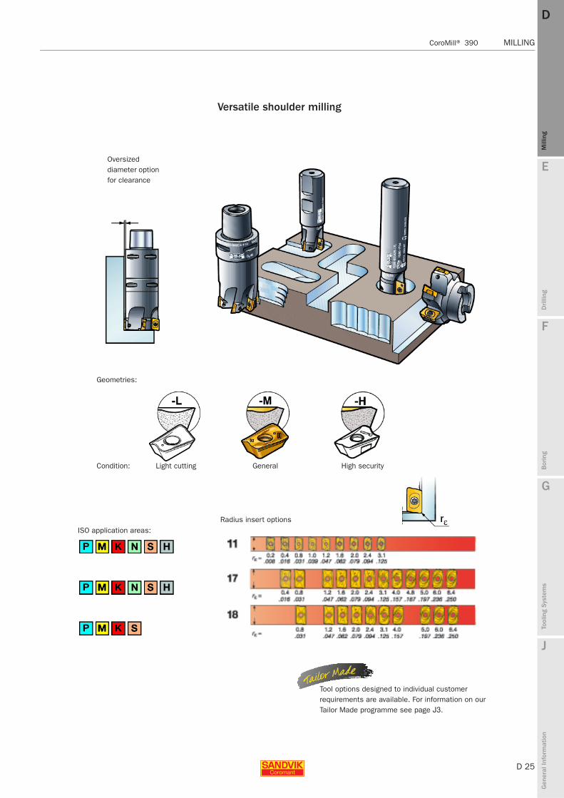
Versatile shoulder milling
Oversized diameter option for clearance
Geometries:
Condition:
ISO application areas:
GeneralLight cutting High security
Radius insert options
Tool options designed to individual customer requirements are available. For information on our Tailor Made programme see page J3.
D 26
MILLING CoroMill® 390
E
Mill
ing
Drilli
ng
F
Bor
ing
G
Tool
ing
Syst
ems
J
Gen
eral
Info
rmat
ion
DDM
illin
g
MILLING CoroMill® 390
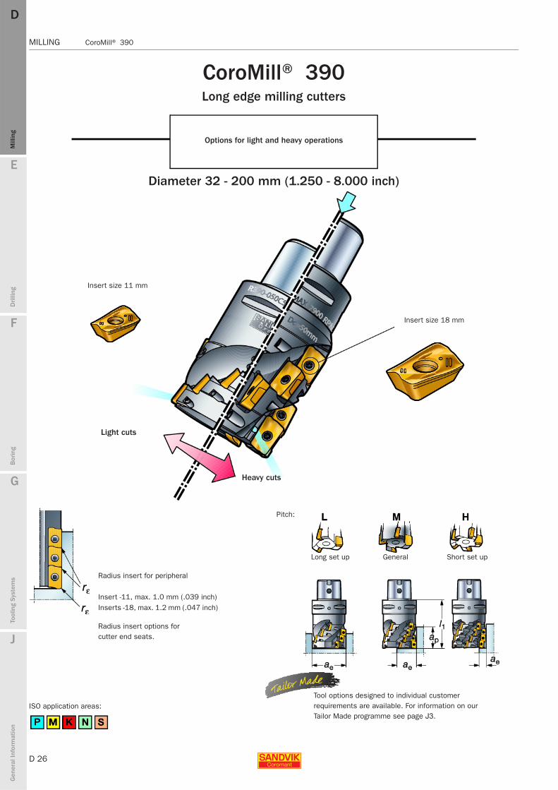
CoroMill® 390 Long edge milling cutters
Options for light and heavy operations
Diameter 32 - 200 mm (1.250 - 8.000 inch)
Insert size 11 mm
Radius insert options for cutter end seats.
Radius insert for peripheral
Insert -11, max. 1.0 mm (.039 inch)Inserts -18, max. 1.2 mm (.047 inch)
ISO application areas:
Light cuts
Insert size 18 mm
Heavy cuts
Pitch:
Long set up General Short set up
Tool options designed to individual customer requirements are available. For information on our Tailor Made programme see page J3.
E
D 27
Mill
ing
Drilli
ng
F
Bor
ing
G
Tool
ing
Syst
ems
J
Gen
eral
Info
rmat
ion
DD
Mill
ing
CoroMill® 390 MILLING
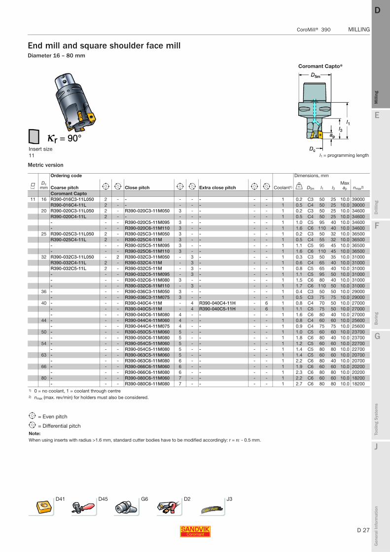
MILLING CoroMill® 390
End mill and square shoulder face millDiameter 16 – 80 mm
Metric version
Coromant Capto®
Insert size 11 l1 = programming length
Ordering code Dimensions, mm
KDc
mm Coarse pitch e i Close pitch e i Extra close pitch e i Coolant1) U D5m l1 l3Max ap nmax2)
Coromant Capto 11 16 R390-016C3-11L050 2 - - - - - - - 1 0.2 C3 50 25 10.0 39000
R390-016C4-11L 2 - - - - - - - 1 0.5 C4 50 25 10.0 3900020 R390-020C3-11L050 2 - R390-020C3-11M050 3 - - - - 1 0.2 C3 50 25 10.0 34600
R390-020C4-11L 2 - - - - - - - 1 0.5 C4 50 25 10.0 34600- - - R390-020C5-11M095 3 - - - - 1 1.0 C5 95 40 10.0 34600- - - R390-020C6-11M110 3 - - - - 1 1.6 C6 110 40 10.0 34600
25 R390-025C3-11L050 2 - R390-025C3-11M050 3 - - - - 1 0.2 C3 50 32 10.0 36500R390-025C4-11L 2 - R390-025C4-11M 3 - - - - 1 0.5 C4 55 32 10.0 36500- - - R390-025C5-11M095 3 - - - - 1 1.1 C5 95 45 10.0 36500- - - R390-025C6-11M110 3 - - - - 1 1.6 C6 110 45 10.0 36500
32 R390-032C3-11L050 - 2 R390-032C3-11M050 - 3 - - - 1 0.3 C3 50 35 10.0 31000R390-032C4-11L 2 - R390-032C4-11M - 3 - - - 1 0.6 C4 65 40 10.0 31000R390-032C5-11L 2 - R390-032C5-11M - 3 - - - 1 0.8 C5 65 40 10.0 31000- - - R390-032C5-11M095 - 3 - - - 1 1.1 C5 95 50 10.0 31000- - - R390-032C6-11M080 3 - - - - 1 1.5 C6 80 40 10.0 31000- - - R390-032C6-11M110 - 3 - - - 1 1.7 C6 110 50 10.0 31000
36 - - - R390-036C3-11M050 3 - - - - 1 0.4 C3 50 50 10.0 29000- - - R390-036C3-11M075 3 - - - - 1 0.5 C3 75 75 10.0 29000
40 - - - R390-040C4-11M - 4 R390-040C4-11H - 6 1 0.8 C4 70 50 10.0 27000- - - R390-040C5-11M - 4 R390-040C5-11H - 6 1 1.1 C5 75 50 10.0 27000- - - R390-040C6-11M080 4 - - - - 1 1.6 C6 80 40 10.0 27000
44 - - - R390-044C4-11M060 4 - - - - 1 0.8 C4 60 60 10.0 25600- - - R390-044C4-11M075 4 - - - - 1 0.9 C4 75 75 10.0 25600
50 - - - R390-050C5-11M060 5 - - - - 1 1.0 C5 60 60 10.0 23700- - - R390-050C6-11M080 5 - - - - 1 1.8 C6 80 40 10.0 23700
54 - - - R390-054C5-11M060 5 - - - - 1 1.2 C5 60 60 10.0 22700- - - R390-054C5-11M080 5 - - - - 1 1.4 C5 80 80 10.0 22700
63 - - - R390-063C5-11M060 5 - - - - 1 1.4 C5 60 60 10.0 20700- - - R390-063C6-11M080 6 - - - - 1 2.2 C6 80 40 10.0 20700
66 - - - R390-066C6-11M060 6 - - - - 1 1.9 C6 60 60 10.0 20200- - - R390-066C6-11M080 6 - - - - 1 2.3 C6 80 80 10.0 20200
80 - - - R390-080C6-11M060 7 - - - - 1 2.2 C6 60 60 10.0 18200- - - R390-080C6-11M080 7 - - - - 1 2.7 C6 80 80 10.0 18200
1) 0 = no coolant, 1 = coolant through centre2) nmax (max. rev/min) for holders must also be considered.
e = Even pitch
i = Differential pitchNote:When using inserts with radius >1.6 mm, standard cutter bodies have to be modified accordingly: r = rε - 0.5 mm.
D41 D45 G6 D2 J3
D 28
MILLING CoroMill® 390
E
Mill
ing
Drilli
ng
F
Bor
ing
G
Tool
ing
Syst
ems
J
Gen
eral
Info
rmat
ion
DDM
illin
g
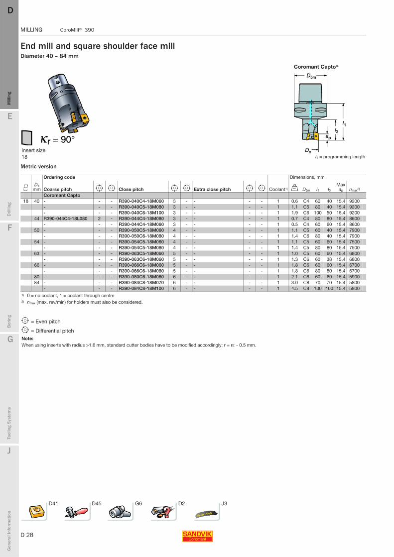
MILLING CoroMill® 390
End mill and square shoulder face millDiameter 40 – 84 mm
Metric version
Coromant Capto®
Insert size 18 l1 = programming length
Ordering code Dimensions, mm
KDc
mm Coarse pitch e i Close pitch e i Extra close pitch e i Coolant1) U D5m l1 l3Max ap nmax2)
Coromant Capto 18 40 - - - R390-040C4-18M060 3 - - - - 1 0.6 C4 60 40 15.4 9200
- - - R390-040C5-18M080 3 - - - - 1 1.1 C5 80 40 15.4 9200- - - R390-040C6-18M100 3 - - - - 1 1.9 C6 100 50 15.4 9200
44 R390-044C4-18L080 2 - R390-044C4-18M080 3 - - - - 1 0.7 C4 80 80 15.4 8600- - - R390-044C4-18M060 3 - - - - 1 0.5 C4 60 60 15.4 8600
50 - - - R390-050C5-18M060 4 - - - - 1 1.1 C5 60 40 15.4 7900- - - R390-050C6-18M080 4 - - - - 1 1.4 C6 80 40 15.4 7900
54 - - - R390-054C5-18M060 4 - - - - 1 1.1 C5 60 60 15.4 7500- - - R390-054C5-18M080 4 - - - - 1 1.4 C5 80 80 15.4 7500
63 - - - R390-063C5-18M060 5 - - - - 1 1.0 C5 60 60 15.4 6800- - - R390-063C6-18M060 5 - - - - 1 1.3 C6 60 38 15.4 6800
66 - - - R390-066C6-18M060 5 - - - - 1 1.8 C6 60 60 15.4 6700- - - R390-066C6-18M080 5 - - - - 1 1.8 C6 80 80 15.4 6700
80 - - - R390-080C6-18M060 6 - - - - 1 2.1 C6 60 60 15.4 590084 - - - R390-084C8-18M070 6 - - - - 1 3.0 C8 70 70 15.4 5800
- - - R390-084C8-18M100 6 - - - - 1 4.5 C8 100 100 15.4 58001) 0 = no coolant, 1 = coolant through centre2) nmax (max. rev/min) for holders must also be considered.
e = Even pitch
i = Differential pitchNote:When using inserts with radius >1.6 mm, standard cutter bodies have to be modified accordingly: r = rε - 0.5 mm.
D41 D45 G6 D2 J3
E
D 29
Mill
ing
Drilli
ng
F
Bor
ing
G
Tool
ing
Syst
ems
J
Gen
eral
Info
rmat
ion
DD
Mill
ing
CoroMill® 390 MILLING
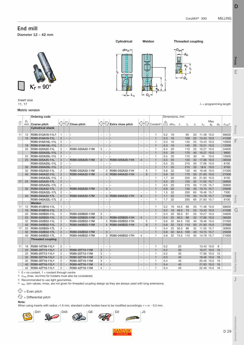
MILLING CoroMill® 390
End millDiameter 12 – 42 mm
Metric version
Cylindrical Weldon Threaded coupling
Insert size 11, 17 l1 = programming length
Ordering code Dimensions, mm
KDc
mm Coarse pitch e i Close pitch e i Extra close pitch e i Coolant1) U dmm l1 l2 l3 λs
Max ap dth nmax2)
Cylindrical shank
11 12 R390-012A16-11L3) 1 - - - - - - - 1 0.2 16 95 20 11.48 10.0 6860016 R390-016A16-11L 2 - - - - - - - 1 0.3 16 100 25 13.43 10.0 41500
R390-016A16L-11L 2 - - - - - - - 1 0.3 16 145 25 13.43 10.0 1090018 R390-018A16L-11L 2 - - - - - - - 1 0.3 16 145 25 10.31 10.0 1220020 R390-020A20-11L 2 - R390-020A20-11M 3 - - - - 1 0.4 20 110 25 10.27 10.0 34600
R390-020A20L-11L 2 - - - - - - - 1 0.5 20 170 40 10.27 10.0 990022 R390-022A20L-11L 2 - - - - - - - 1 0.5 20 170 30 14 10.0 1090025 R390-025A25-11L 2 - R390-025A25-11M 3 - R390-025A25-11H 4 - 1 0.5 25 120 32 17.06 10.0 36500
R390-025A25L-11L 2 - - - - - - - 1 0.5 25 210 50 17.06 10.0 810030 R390-030A25L-11L 2 - - - - - - - 1 1.1 25 210 35 18.8 10.0 970032 R390-032A32-11L 2 - R390-032A32-11M - 3 R390-032A32-11H - 5 1 0.8 32 130 40 19.46 10.0 3100040 R390-040A32-11L 2 - R390-040A32-11M - 4 R390-040A32-11H - 6 1 0.8 32 170 50 21.93 10.0 27000
R390-040A32L-11L 2 - - - - - - - 1 1.7 32 250 65 21.93 10.0 910017 25 R390-025A25-17L 2 - - - - - - - 1 0.5 25 120 32 11.55 15.7 30800
R390-025A25L-17L 2 - - - - - - - 1 0.5 25 210 50 11.55 15.7 3080032 R390-032A32-17L 2 - R390-032A32-17M - 3 - - - 1 0.8 32 130 40 13.15 15.7 25600
R390-032A32L-17L 2 - - - - - - - 1 1.5 32 250 65 19.46 15.7 730040 R390-040A32-17L 2 - R390-040A32-17M - 3 R390-040A32-17H 4 - 1 1.1 32 170 50 14.78 15.7 21900
R390-040A32L-17L 2 - - - - - - - 1 1.7 32 250 65 21.93 15.7 9100Weldon
11 12 R390-012B16-11L 1 - - - - - - - 1 0.2 16 44.5 68 20 11.48 10.0 6860016 R390-016B16-11L 2 - - - - - - - 1 0.2 16 49.5 73 25 13.43 10.0 4150020 R390-020B20-11L 2 - R390-020B20-11M 3 - - - - 1 0.3 20 56.5 81 25 10.27 10.0 3460025 R390-025B25-11L 2 - R390-025B25-11M 3 - R390-025B25-11H 4 - 1 0.4 25 56.5 88 32 17.06 10.0 3650032 R390-032B32-11L 2 - R390-032B32-11M - 3 R390-032B32-11H - 5 1 0.6 32 64.5 100 40 19.46 10.0 3100040 R390-040B32-11L 2 - R390-040B32-11M - 4 R390-040B32-11H - 6 1 0.8 32 74.5 110 50 21.93 10.0 27000
17 25 R390-025B25-17L 2 - - - - - - - 1 0.4 25 56.5 88 32 11.55 15.7 3080032 R390-032B32-17L 2 - R390-032B32-17M - 3 - - - 1 0.8 32 64.5 100 40 13.15 15.7 2560040 R390-040B32-17L 2 - R390-040B32-17M - 3 R390-040B32-17H 4 - 1 0.8 32 74.5 110 50 14.78 15.7 21900
Threaded coupling
11 16 R390-16T08-11L4) 2 - - - - - - - 1 0.2 25 13.43 10.0 820 R390-20T10-11L4) 2 - R390-20T10-11M 3 - - - - 1 0.2 30 10.27 10.0 1025 R390-25T12-11L4) 2 - R390-25T12-11M 3 - - - - 1 0.2 35 17.06 10.0 1232 R390-32T16-11L4) 2 - R390-32T16-11M 3 - - - - 1 0.3 45 19.46 10.0 1635 R390-35T16-11L4) 2 - R390-35T16-11M 3 - - - - 1 0.4 45 20.46 10.0 1640 R390-40T16-11L4) 2 - R390-40T16-11M 4 - - - - 1 0.4 45 21.93 10.0 1642 R390-42T16-11L4) 2 - R390-42T16-11M 4 - - - - 1 0.4 45 22.49 10.0 16
1) 0 = no coolant, 1 = coolant through centre2) nmax (max. rev/min) for holders must also be considered.3) Recommended to use light geometries.4) Max. rpm values, nmax, are not given for threaded coupling design as they are always used with long extensions.
e = Even pitch
i = Differential pitchNote:When using inserts with radius >1.6 mm, standard cutter bodies have to be modified accordingly: r = rε - 0.5 mm.
D41 D45 G6 D2 J3
D 30
MILLING CoroMill® 390
E
Mill
ing
Drilli
ng
F
Bor
ing
G
Tool
ing
Syst
ems
J
Gen
eral
Info
rmat
ion
DDM
illin
g
MILLING CoroMill® 390
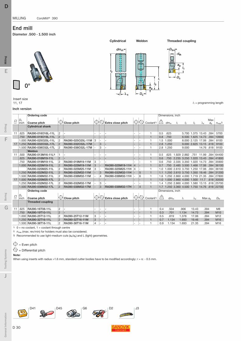
End millDiameter .500 - 1.500 inch
Inch version
Cylindrical Weldon Threaded coupling
Insert size 11, 17 l1 = programming length
Ordering code Dimensions, inch
KDc inch Coarse pitch e Close pitch e i Extra close pitch e i Coolant1) V dmm l1 l2 l3 λs
Max ap nmax2)
Cylindrical shank
11 .625 RA390-016O16L-11L 2 - - - - - - 1 0.5 .625 5.700 1.375 13.43 .394 5700.750 RA390-019O19L-11L 2 - - - - - - 1 0.8 .750 6.500 1.625 14.73 .394 109001.000 RA390-025O25L-11L 2 RA390-025O25L-11M 3 - - - - 1 1.5 1.000 8.000 2.125 17.06 .394 8100
17 1.250 RA390-032O32L-17L 2 RA390-032O32L-17M - 3 - - - 1 2.8 1.250 9.000 2.625 13.15 .618 91001.500 RA390-038O32L-17L 2 RA390-038O32L-17M - 3 - - - 1 2.8 1.250 9.000 14.76 .618 9100
Weldon11 .500 RA390-013M16-11L3) 1 - - - - - - 1 0.5 .625 1.929 2.882 .751 11.99 .394 64400
.625 RA390-016M19-11L 2 - - - - - - 1 0.6 .750 2.235 3.250 1.020 13.43 .394 41800
.750 RA390-019M19-11L 2 RA390-019M19-11M 3 - - - - 1 0.6 .750 2.335 3.350 1.020 14.73 .394 359001.000 RA390-025M19-11L 2 RA390-025M19-11M 3 - RA390-025M19-11H 4 - 1 0.7 .750 2.485 3.500 1.468 17.06 .394 36100
RA390-025M25-11L 2 RA390-025M25-11M 3 - RA390-025M25-11H 4 - 1 1.0 1.000 2.610 3.750 1.250 17.06 .394 361001.250 RA390-032M32-11L 2 RA390-032M32-11M - 3 RA390-032M32-11H - 5 1 1.1 1.250 2.610 3.750 1.350 19.46 .394 312001.500 RA390-038M32-11L 2 RA390-038M32-11M - 4 RA390-038M32-11H - 6 1 1.6 1.250 2.860 4.000 1.719 21.35 .394 27800
17 1.000 RA390-025M25-17L 2 - - - - - - 1 1.0 1.000 2.860 4.000 1.500 11.7 .618 305001.250 RA390-032M32-17L 2 RA390-032M32-17M - 3 - - - 1 1.4 1.250 2.860 4.000 1.580 13.15 .618 257001.500 RA390-038M32-17L 2 RA390-038M32-17M - 3 RA390-038M32-17H - 4 1 1.7 1.250 3.360 4.500 1.750 14.76 .618 22700
Ordering code Dimensions, inch
KDc inch Coarse pitch e Close pitch e i Extra close pitch e i Coolant1) V dmm l1 λs Max ap Dth
Threaded coupling
11 .625 RA390-16T08-11L 2 - - - - - - 1 0.4 .504 .906 13.43 .394 M8.750 RA390-19T10-11L 2 - - - - - - 1 0.3 .701 1.134 14.73 .394 M101.000 RA390-25T12-11L 2 RA390-25T12-11M 3 - - - - 1 0.5 .819 1.378 17.06 .394 M121.250 RA390-32T16-11L 2 RA390-32T16-11M 3 - - - - 1 0.7 1.134 1.693 19.46 .394 M161.500 RA390-38T16-11L 2 RA390-38T16-11M 4 - - - - 1 0.9 1.134 1.693 21.35 .394 M16
1) 0 = no coolant, 1 = coolant through centre2) nmax (max. rev/min) for holders must also be considered.3) Recommended to use light-medium cuts (ae/ap) and L (light) geometries.
e = Even pitch
i = Differential pitchNote:When using inserts with radius >1.6 mm, standard cutter bodies have to be modified accordingly: r = rε - 0.5 mm.
D41 D45 G6 D2 J3

E
D 31
Mill
ing
Drilli
ng
F
Bor
ing
G
Tool
ing
Syst
ems
J
Gen
eral
Info
rmat
ion
DD
Mill
ing
CoroMill® 390 MILLING
MILLING CoroMill® 390
Square shoulder face millDiameter 40 – 200 mm
Metric version
Arbor
Insert size 11, 17, 18 l1 = programming length
Ordering code Dimensions, mm
KDc
mm Coarse pitch e i Close pitch e i Extra close pitch e i U dmm l1 Max ap nmax1)
Arbor
11 40 - - - R390-040Q16-11M - 4 R390-040Q16-11H - 6 0.4 16 40 10.0 2700050 - - - R390-050Q22-11M - 5 R390-050Q22-11H - 7 0.5 22 40 10.0 2370063 - - - R390-063Q22-11M - 6 R390-063Q22-11H - 8 0.6 22 40 10.0 2070080 - - - R390-080Q27-11M - 7 R390-080Q27-11H - 10 0.9 27 50 10.0 18200
17 40 R390-040Q16-17L 2 - R390-040Q16-17M - 3 R390-040Q16-17H 4 - 0.3 16 40 15.7 2190050 R390-050Q22-17L - 3 R390-050Q22-17M - 4 R390-050Q22-17H - 5 0.4 22 40 15.7 1900063 R390-063Q22-17L - 4 R390-063Q22-17M - 5 R390-063Q22-17H - 6 0.6 22 40 15.7 1650080 R390-080Q27-17L - 4 R390-080Q27-17M - 6 R390-080Q27-17H - 8 0.8 27 50 15.7 14400
100 R390-100Q32-17L - 5 R390-100Q32-17M - 7 R390-100Q32-17H - 9 1.0 32 50 15.7 12700125 R390-125Q40-17L - 6 R390-125Q40-17M - 8 R390-125Q40-17H - 11 2.7 40 63 15.7 11200
18 50 R390-050Q22-18L - 3 R390-050Q22-18M - 4 R390-050Q22-18H 5 - 0.6 22 40 15.7 790063 R390-063Q22-18L - 4 R390-063Q22-18M - 5 R390-063Q22-18H 6 - 0.8 22 40 15.7 680080 R390-080Q27-18L - 4 R390-080Q27-18M - 6 - - - 1.1 27 50 15.7 5900
100 R390-100Q32-18L - 5 R390-100Q32-18M - 7 - - - 1.8 32 50 15.7 5200125 R390-125Q40-18L - 6 R390-125Q40-18M - 8 - - - 2.7 40 63 15.7 4600160 R390-160Q40-18L - 8 R390-160Q40-18M - 12 - - - 3.9 40 63 15.7 4000200 R390-200Q60-18L - 10 - - - - - - 10.0 60 63 15.7 3600
CIS Arbor
17 80 RA390-080J25.4-17L - 4 RA390-080J25.4-17M - 6 RA390-080J25.4-17H - 8 1.0 25.4 50 15.7 1440018 80 - - - RA390-080J25.4-18M - 6 - - - 1.2 25.4 50 15.7 5900
125 - - - RA390-125J38.1-18M - 8 - - - 3.0 38.1 63 15.7 4600160 - - - RA390-160J50.8-18M - 12 - - - 9.8 50.8 63 15.7 4000
1) nmax (max. rev/min) for holders must also be considered.
Note:Bolt circle for cutters 200 and 250mm = 4"When using inserts with radius >1.6 mm, standard cutter bodies have to be modified accordingly: r = rε - 0.5 mm.
e = Even pitch
i = Differential pitch
D41 D45 G6 D2 J3
D 32
MILLING CoroMill® 390
E
Mill
ing
Drilli
ng
F
Bor
ing
G
Tool
ing
Syst
ems
J
Gen
eral
Info
rmat
ion
DDM
illin
g
MILLING CoroMill® 390
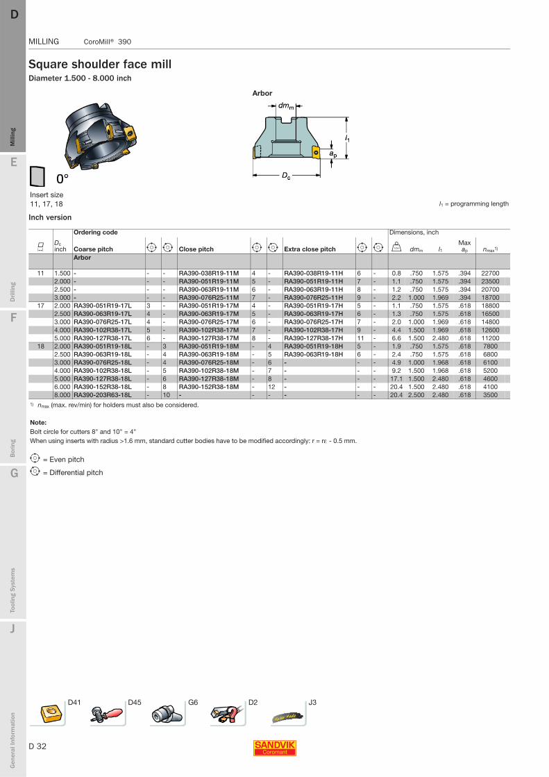
Square shoulder face millDiameter 1.500 - 8.000 inch
Inch version
Arbor
Insert size 11, 17, 18 l1 = programming length
Ordering code Dimensions, inch
KDc inch Coarse pitch e i Close pitch e i Extra close pitch e i V dmm l1
Max ap nmax1)
Arbor
11 1.500 - - - RA390-038R19-11M 4 - RA390-038R19-11H 6 - 0.8 .750 1.575 .394 227002.000 - - - RA390-051R19-11M 5 - RA390-051R19-11H 7 - 1.1 .750 1.575 .394 235002.500 - - - RA390-063R19-11M 6 - RA390-063R19-11H 8 - 1.2 .750 1.575 .394 207003.000 - - - RA390-076R25-11M 7 - RA390-076R25-11H 9 - 2.2 1.000 1.969 .394 18700
17 2.000 RA390-051R19-17L 3 - RA390-051R19-17M 4 - RA390-051R19-17H 5 - 1.1 .750 1.575 .618 188002.500 RA390-063R19-17L 4 - RA390-063R19-17M 5 - RA390-063R19-17H 6 - 1.3 .750 1.575 .618 165003.000 RA390-076R25-17L 4 - RA390-076R25-17M 6 - RA390-076R25-17H 7 - 2.0 1.000 1.969 .618 148004.000 RA390-102R38-17L 5 - RA390-102R38-17M 7 - RA390-102R38-17H 9 - 4.4 1.500 1.969 .618 126005.000 RA390-127R38-17L 6 - RA390-127R38-17M 8 - RA390-127R38-17H 11 - 6.6 1.500 2.480 .618 11200
18 2.000 RA390-051R19-18L - 3 RA390-051R19-18M - 4 RA390-051R19-18H 5 - 1.9 .750 1.575 .618 78002.500 RA390-063R19-18L - 4 RA390-063R19-18M - 5 RA390-063R19-18H 6 - 2.4 .750 1.575 .618 68003.000 RA390-076R25-18L - 4 RA390-076R25-18M - 6 - - - 4.9 1.000 1.968 .618 61004.000 RA390-102R38-18L - 5 RA390-102R38-18M - 7 - - - 9.2 1.500 1.968 .618 52005.000 RA390-127R38-18L - 6 RA390-127R38-18M - 8 - - - 17.1 1.500 2.480 .618 46006.000 RA390-152R38-18L - 8 RA390-152R38-18M - 12 - - - 20.4 1.500 2.480 .618 41008.000 RA390-203R63-18L - 10 - - - - - - 20.4 2.500 2.480 .618 3500
1) nmax (max. rev/min) for holders must also be considered.
Note:Bolt circle for cutters 8" and 10" = 4"When using inserts with radius >1.6 mm, standard cutter bodies have to be modified accordingly: r = rε - 0.5 mm.
e = Even pitch
i = Differential pitch
D41 D45 G6 D2 J3
E
D 33
Mill
ing
Drilli
ng
F
Bor
ing
G
Tool
ing
Syst
ems
J
Gen
eral
Info
rmat
ion
DD
Mill
ing
CoroMill® 390 MILLING
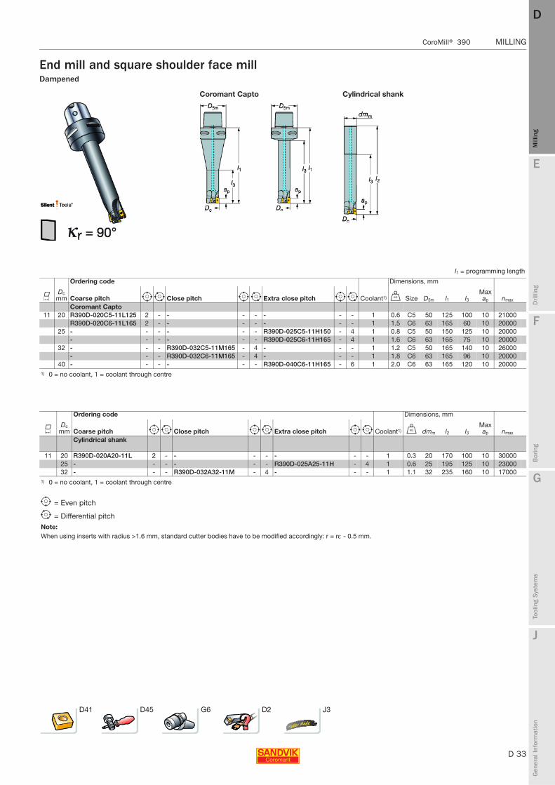
MILLING CoroMill® 390
End mill and square shoulder face millDampened
Coromant Capto Cylindrical shank
l1 = programming length
Ordering code Dimensions, mm
KDc
mm Coarse pitch e i Close pitch e i Extra close pitch e i Coolant1) U Size D5m l1 l3Max ap nmax
Coromant Capto 11 20 R390D-020C5-11L125 2 - - - - - - - 1 0.6 C5 50 125 100 10 21000
R390D-020C6-11L165 2 - - - - - - - 1 1.5 C6 63 165 60 10 2000025 - - - - - - R390D-025C5-11H150 - 4 1 0.8 C5 50 150 125 10 20000
- - - - - - R390D-025C6-11H165 - 4 1 1.6 C6 63 165 75 10 2000032 - - - R390D-032C5-11M165 - 4 - - - 1 1.2 C5 50 165 140 10 26000
- - - R390D-032C6-11M165 - 4 - - - 1 1.8 C6 63 165 96 10 2000040 - - - - - - R390D-040C6-11H165 - 6 1 2.0 C6 63 165 120 10 20000
1) 0 = no coolant, 1 = coolant through centre
Ordering code Dimensions, mm
KDc
mm Coarse pitch e i Close pitch e i Extra close pitch e i Coolant1) U dmm l2 l3Max ap nmax
Cylindrical shank
11 20 R390D-020A20-11L 2 - - - - - - - 1 0.3 20 170 100 10 3000025 - - - - - - R390D-025A25-11H - 4 1 0.6 25 195 125 10 2300032 - - - R390D-032A32-11M - 4 - - - 1 1.1 32 235 160 10 17000
1) 0 = no coolant, 1 = coolant through centre
e = Even pitch
i = Differential pitchNote:When using inserts with radius >1.6 mm, standard cutter bodies have to be modified accordingly: r = rε - 0.5 mm.
D41 D45 G6 D2 J3
D 34
MILLING CoroMill® 390
E
Mill
ing
Drilli
ng
F
Bor
ing
G
Tool
ing
Syst
ems
J
Gen
eral
Info
rmat
ion
DDM
illin
g
MILLING CoroMill® 390
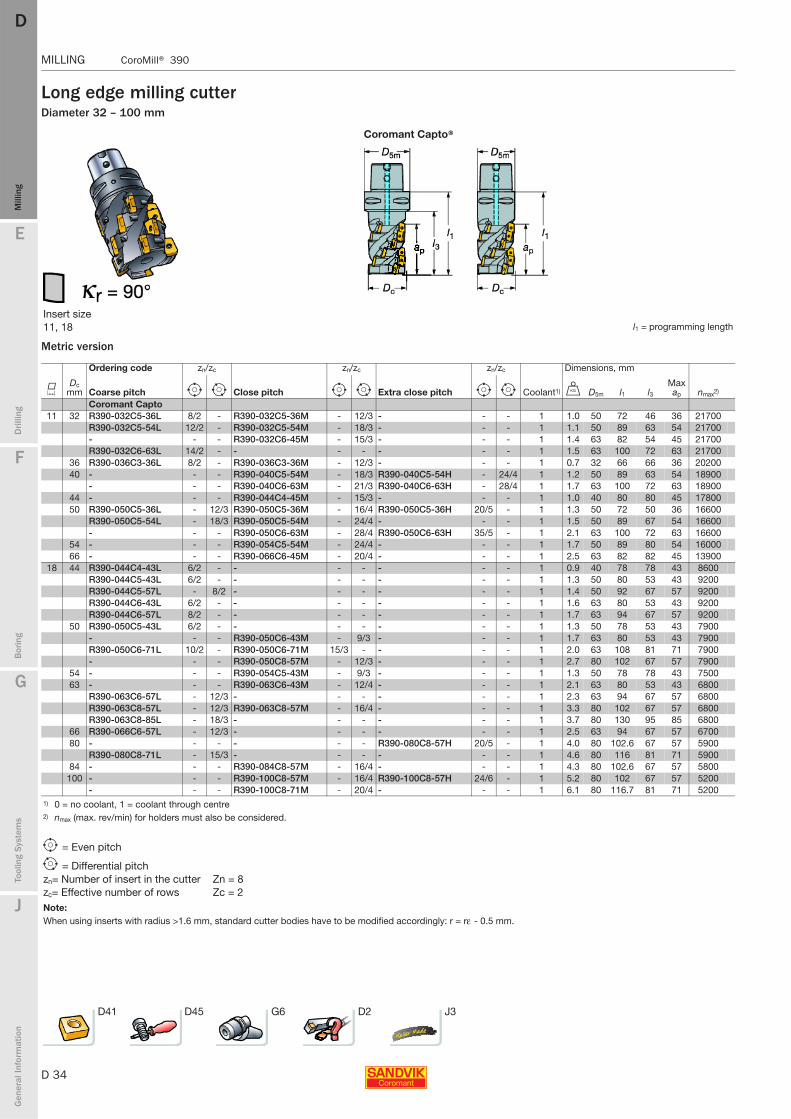
Long edge milling cutterDiameter 32 – 100 mm
Metric version
Coromant Capto®
Insert size 11, 18 l1 = programming length
Ordering code zn/zc zn/zc zn/zc Dimensions, mm
KDc
mm Coarse pitch e i Close pitch e i Extra close pitch e i Coolant1) U D5m l1 l3Max ap nmax2)
Coromant Capto 11 32 R390-032C5-36L 8/2 - R390-032C5-36M - 12/3 - - - 1 1.0 50 72 46 36 21700
R390-032C5-54L 12/2 - R390-032C5-54M - 18/3 - - - 1 1.1 50 89 63 54 21700- - - R390-032C6-45M - 15/3 - - - 1 1.4 63 82 54 45 21700R390-032C6-63L 14/2 - - - - - - - 1 1.5 63 100 72 63 21700
36 R390-036C3-36L 8/2 - R390-036C3-36M - 12/3 - - - 1 0.7 32 66 66 36 2020040 - - - R390-040C5-54M - 18/3 R390-040C5-54H - 24/4 1 1.2 50 89 63 54 18900
- - - R390-040C6-63M - 21/3 R390-040C6-63H - 28/4 1 1.7 63 100 72 63 1890044 - - - R390-044C4-45M - 15/3 - - - 1 1.0 40 80 80 45 1780050 R390-050C5-36L - 12/3 R390-050C5-36M - 16/4 R390-050C5-36H 20/5 - 1 1.3 50 72 50 36 16600
R390-050C5-54L - 18/3 R390-050C5-54M - 24/4 - - - 1 1.5 50 89 67 54 16600- - - R390-050C6-63M - 28/4 R390-050C6-63H 35/5 - 1 2.1 63 100 72 63 16600
54 - - - R390-054C5-54M - 24/4 - - - 1 1.7 50 89 80 54 1600066 - - - R390-066C6-45M - 20/4 - - - 1 2.5 63 82 82 45 13900
18 44 R390-044C4-43L 6/2 - - - - - - - 1 0.9 40 78 78 43 8600R390-044C5-43L 6/2 - - - - - - - 1 1.3 50 80 53 43 9200R390-044C5-57L - 8/2 - - - - - - 1 1.4 50 92 67 57 9200R390-044C6-43L 6/2 - - - - - - - 1 1.6 63 80 53 43 9200R390-044C6-57L 8/2 - - - - - - - 1 1.7 63 94 67 57 9200
50 R390-050C5-43L 6/2 - - - - - - - 1 1.3 50 78 53 43 7900- - - R390-050C6-43M - 9/3 - - - 1 1.7 63 80 53 43 7900R390-050C6-71L 10/2 - R390-050C6-71M 15/3 - - - - 1 2.0 63 108 81 71 7900- - - R390-050C8-57M - 12/3 - - - 1 2.7 80 102 67 57 7900
54 - - - R390-054C5-43M - 9/3 - - - 1 1.3 50 78 78 43 750063 - - - R390-063C6-43M - 12/4 - - - 1 2.1 63 80 53 43 6800
R390-063C6-57L - 12/3 - - - - - - 1 2.3 63 94 67 57 6800R390-063C8-57L - 12/3 R390-063C8-57M - 16/4 - - - 1 3.3 80 102 67 57 6800R390-063C8-85L - 18/3 - - - - - - 1 3.7 80 130 95 85 6800
66 R390-066C6-57L - 12/3 - - - - - - 1 2.5 63 94 67 57 670080 - - - - - - R390-080C8-57H 20/5 - 1 4.0 80 102.6 67 57 5900
R390-080C8-71L - 15/3 - - - - - - 1 4.6 80 116 81 71 590084 - - - R390-084C8-57M - 16/4 - - - 1 4.3 80 102.6 67 57 5800
100 - - - R390-100C8-57M - 16/4 R390-100C8-57H 24/6 - 1 5.2 80 102 67 57 5200- - - R390-100C8-71M - 20/4 - - - 1 6.1 80 116.7 81 71 5200
1) 0 = no coolant, 1 = coolant through centre2) nmax (max. rev/min) for holders must also be considered.
e = Even pitch
i = Differential pitchzn= Number of insert in the cutter Zn = 8zc= Effective number of rows Zc = 2Note:When using inserts with radius >1.6 mm, standard cutter bodies have to be modified accordingly: r = rε - 0.5 mm.
D41 D45 G6 D2 J3
E
D 35
Mill
ing
Drilli
ng
F
Bor
ing
G
Tool
ing
Syst
ems
J
Gen
eral
Info
rmat
ion
DD
Mill
ing
CoroMill® 390 MILLING
MILLING CoroMill® 390
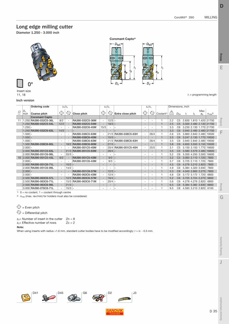
Long edge milling cutterDiameter 1.250 - 3.000 inch
Inch version
Coromant Capto®
Insert size 11, 18 l1 = programming length
Ordering code zn/zc zn/zc zn/zc Dimensions, inch
KDc inch Coarse pitch e i Close pitch e i Extra close pitch e i Coolant1) V D5m l1 l3
Max ap nmax2)
Coromant Capto 11 1.250 RA390-032C5-36L 8/2 - RA390-032C5-36M - 12/3 - - - 1 2.2 C5 2.830 1.810 1.420 21700
1.250 RA390-032C5-54L 12/2 - RA390-032C5-54M - 18/3 - - - 1 2.5 C5 3.500 2.480 2.130 217001.250 - - - RA390-032C6-45M 15/3 - - - - 1 3.3 C6 3.230 2.130 1.770 217001.250 RA390-032C6-63L 14/2 - - - - - - - 1 3.3 C6 3.940 2.480 2.480 217001.500 - - - RA390-038C5-63M - 21/3 RA390-038C5-63H - 28/4 1 2.6 C5 3.860 2.840 2.480 195001.500 - - - RA390-038C6-45M - 15/3 - - - 1 3.5 C6 3.247 2.130 1.770 195001.500 - - - RA390-038C6-63M - 21/3 RA390-038C6-63H - 28/4 1 3.5 C6 3.940 2.840 2.480 195001.500 RA390-038C6-80L - 18/2 RA390-038C6-80M - 27/3 - - - 1 3.8 C6 4.650 3.550 3.150 195002.000 - - - RA390-051C5-45M - 20/4 RA390-051C5-45H - 25/5 1 3.1 C5 3.150 3.150 1.770 166002.000 RA390-051C5-63L - 21/3 RA390-051C5-63M - 28/4 - - - 1 3.5 C5 3.580 3.579 2.480 166002.000 RA390-051C6-98L - 33/3 - - - - - - 1 5.2 C6 5.350 4.250 3.500 16600
18 2.000 RA390-051C5-43L 6/2 - RA390-051C5-43M - 9/3 - - - 1 3.2 C5 3.093 2.110 1.720 78002.000 - - - RA390-051C6-43M - 9/3 - - - 1 3.7 C6 3.725 2.110 1.720 78002.000 RA390-051C6-71L - 10/2 - - - - - - 1 4.5 C6 4.278 3.210 2.820 78002.000 RA390-051C6-99L - 14/2 - - - - - - 1 4.9 C6 5.384 4.320 3.930 78002.000 - - - RA390-051C8-57M - 12/3 - - - 1 5.3 C8 4.040 2.660 2.270 78002.500 - - - RA390-063C6-43M - 12/4 - - - 1 4.6 C6 3.172 3.172 1.720 68002.500 RA390-063C6-57L - 12/3 RA390-063C6-57M - 16/4 - - - 1 5.2 C6 3.725 3.724 2.270 68002.500 RA390-063C6-71L - 15/3 RA390-063C6-71M - 20/4 - - - 1 5.6 C6 4.278 4.276 2.820 68002.500 RA390-063C6-99L - 21/3 - - - - - - 1 6.5 C6 5.384 5.382 3.930 68003.000 RA390-076C8-71L - 15/3 - - - - - - 1 9.5 C8 4.593 3.210 2.820 6100
1) 0 = no coolant, 1 = coolant through centre2) nmax (max. rev/min) for holders must also be considered.
e = Even pitch
i = Differential pitch
zn= Number of insert in the cutter Zn = 8zc= Effective number of rows Zc = 2Note:When using inserts with radius >1.6 mm, standard cutter bodies have to be modified accordingly: r = rε - 0.5 mm.
D41 D45 G6 D2 J3

D 36
MILLING CoroMill® 390
E
Mill
ing
Drilli
ng
F
Bor
ing
G
Tool
ing
Syst
ems
J
Gen
eral
Info
rmat
ion
DDM
illin
g
MILLING CoroMill® 390
Long edge milling cutterDiameter 32 – 200 mm
Metric version
Cylindrical Arbor
Insert size 11, 18 l1 = programming length
Ordering code Dimensions, mm
KDc
mm Coarse pitch e i Close pitch e i Extra close pitch e i U dmm l1 l2 l3Max ap nmax1)
Cylindrical shank
11 32 R390-032A25-36L 8/2 - - - - - - - 0.6 25 109 48 36 21700R390-032A32-36L 8/2 - - - - - - - 0.9 32 113 48 36 21700
40 - - - R390-040A40-45M - 15/3 - - - 1.4 40 131 58 45 18900Arbor
11 40 - - - R390-040Q16-36M - 12/3 R390-040Q16-36H 16/4 - 0.8 16 57 36 1890044 - - - R390-044Q16-45M - 15/3 - - - 0.9 16 65 45 1780050 - - - R390-050Q22-36M - 16/4 R390-050Q22-36H 20/5 - 1.0 22 57 36 16600
R390-050Q22-54L - 18/3 - - - - - - 1.1 22 74 54 1660054 - - - R390-054Q22-36M - 16/4 - - - 1.0 22 57 36 16000
18 44 R390-044Q16-43L 6/2 - - - - - - - 0.8 16 68 43 860050 R390-050Q22-57L - 8/2 - - - - - - 1.1 22 82 57 790054 R390-054Q22-57L 8/2 - - - - - - - 1.3 22 82 57 750063 R390-063Q27-57L - 12/3 - - - - - - 1.1 27 82 57 680080 R390-080Q32-71L - 15/3 - - - - - - 2.9 32 97 71 5900100 - - - R390-100Q40-57M - 16/4 - - - 3.2 40 82.6 57 5200125 R390-125Q40-43L 18/6 - - - - - - - 4.7 40 68 43 4600160 R390-160Q40-43L 24/8 - - - - - - - 8.5 40 68 43 4000200 R390-200Q60-43L 27/9 - - - - - - - 14.5 60 68 43 3600
1) nmax (max. rev/min) for holders must also be considered.
Note:Bolt circle for cutters 200 and 250mm = 4"
e = Even pitch
i = Differential pitch
zn= Number of insert in the cutter Zn = 18zc= Effective number of rows Zc = 3Note:When using inserts with radius >1.6 mm, standard cutter bodies have to be modified accordingly: r = rε - 0.5 mm.
D41 D45 G6 D2 J3

E
D 37
Mill
ing
Drilli
ng
F
Bor
ing
G
Tool
ing
Syst
ems
J
Gen
eral
Info
rmat
ion
DD
Mill
ing
CoroMill® 390 MILLING
MILLING CoroMill® 390
Long edge milling cutterDiameter 1.250 - 4.000 inch
Inch version
Arbor Weldon
Insert size 11, 18 l1 = programming length
Ordering code Dimensions, inch
KDc inch Coarse pitch e i Close pitch e i Extra close pitch e i V dmm l1 l2
Max ap nmax1)
Weldon11 1.250 RA390-032M32-45L 10/2 - - - - - - - 2.0 1.250 3.220 3.500 1.770 21700
1.500 RA390-038M38-54L 12/2 - - - - - - - 2.9 1.500 4.210 5.418 2.130 195001.500 - - - RA390-038M38-54M - 18/3 - - - 2.9 1.500 4.210 4.210 2.130 19500
Arbor
11 2.000 - - - RA390-051R19-36M - 16/4 RA390-051R19-36H 20/5 - 2.1 .750 2.240 1.420 166002.000 - - - RA390-051R19-54M - 18/3 - - - 2.5 .750 2.910 2.130 16600
18 2.000 - - - RA390-051R19-43M - 9/3 - - - 2.1 .750 2.699 1.720 78002.000 - - - RA390-051R19-57M - 12/3 - - - 2.3 .750 3.252 2.270 78002.500 - - - RA390-063R19-43M - 12/4 - - - 3.1 .750 2.699 1.720 68002.500 - - - RA390-063R25-43M - 16/4 - - - 3.1 1.000 2.699 1.720 68002.500 RA390-063R25-57L - 12/3 - - - - - - 3.1 1.000 3.252 2.270 68003.000 - - - - - - RA390-076R32-43H - 16/4 4.3 1.250 2.699 1.720 61004.000 - - - RA390-102R38-57M - 16/4 RA390-102R38-57H - 24/6 7.2 1.500 3.252 2.270 5200
1) nmax (max. rev/min) for holders must also be considered.
e = Even pitch
i = Differential pitch
zn= Number of insert in the cutter Zn = 12zc= Effective number of rows Zc = 3Note:When using inserts with radius >1.6 mm, standard cutter bodies have to be modified accordingly: r = rε - 0.5 mm.
D41 D45 G6 D2 J3
D 38
MILLING Multi-functional tools CoroPlex™ MT
E
Mill
ing
Drilli
ng
F
Bor
ing
G
Tool
ing
Syst
ems
J
Gen
eral
Info
rmat
ion
DDM
illin
g
MILLING Multi-functional tools CoroPlex™ MT
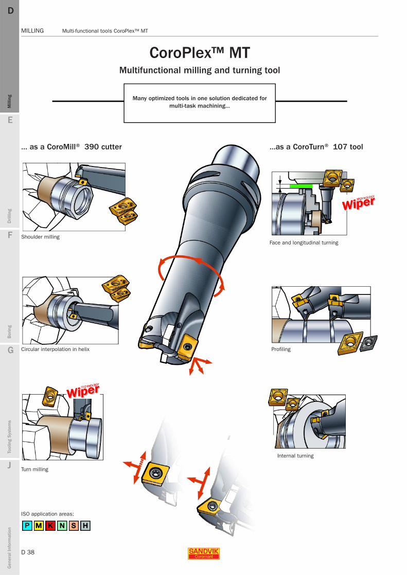
CoroPlex™ MT Multifunctional milling and turning tool
Many optimized tools in one solution dedicated for multi-task machining...
... as a CoroMill® 390 cutter
Shoulder milling
Circular interpolation in helix
Turn milling
ISO application areas:
...as a CoroTurn® 107 tool
Face and longitudinal turning
Profiling
Internal turning
E
D 39
Mill
ing
Drilli
ng
F
Bor
ing
G
Tool
ing
Syst
ems
J
Gen
eral
Info
rmat
ion
DD
Mill
ing
Multi-functional tools CoroPlex™ MT MILLING
MILLING Multi-functional tools CoroPlex™ MT
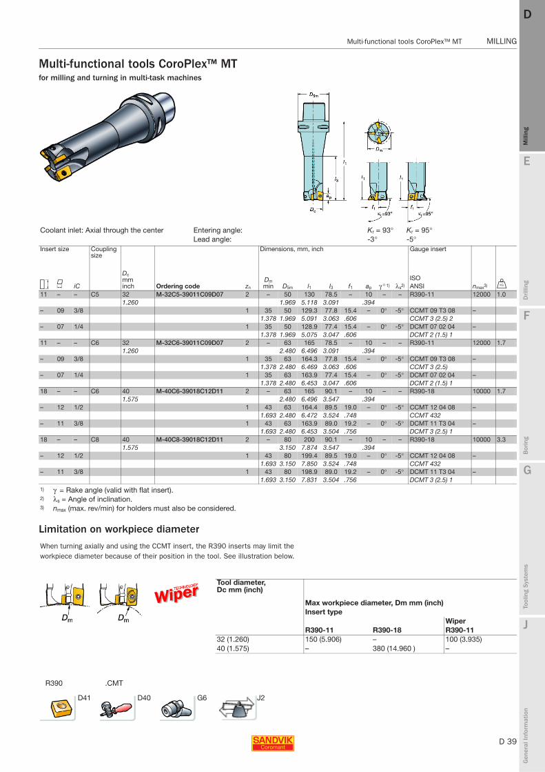
Multi-functional tools CoroPlex™ MTfor milling and turning in multi-task machines
.CMTR390
Limitation on workpiece diameter
Coolant inlet: Axial through the center Entering angle: Kr = 93° Kr = 95°Lead angle: -3° -5°
Insert size Coupling size
Ordering code
Dimensions, mm, inch Gauge insert
C K iC
Dcmminch zn
Dm min D5m l1 l3 f1 ap γ ° 1) λs2)
ISO nmax3) UANSI
11 – – C5 32 M-32C5-39011C09D07 2 – 50 130 78.5 – 10 – – R390-11 12000 1.01.260 1.969 5.118 3.091 .394
– 09 3/8 1 35 50 129.3 77.8 15.4 – 0° -5° CCMT 09 T3 08 –1.378 1.969 5.091 3.063 .606 CCMT 3 (2.5) 2
– 07 1/4 1 35 50 128.9 77.4 15.4 – 0° -5° DCMT 07 02 04 –1.378 1.969 5.075 3.047 .606 DCMT 2 (1.5) 1
11 – – C6 32 M-32C6-39011C09D07 2 – 63 165 78.5 – 10 – – R390-11 12000 1.71.260 2.480 6.496 3.091 .394
– 09 3/8 1 35 63 164.3 77.8 15.4 – 0° -5° CCMT 09 T3 08 –1.378 2.480 6.469 3.063 .606 CCMT 3 (2.5)
– 07 1/4 1 35 63 163.9 77.4 15.4 – 0° -5° DCMT 07 02 04 –1.378 2.480 6.453 3.047 .606 DCMT 2 (1.5) 1
18 – – C6 40 M-40C6-39018C12D11 2 – 63 165 90.1 – 10 – – R390-18 10000 1.71.575 2.480 6.496 3.547 .394
– 12 1/2 1 43 63 164.4 89.5 19.0 – 0° -5° CCMT 12 04 08 –1.693 2.480 6.472 3.524 .748 CCMT 432
– 11 3/8 1 43 63 163.9 89.0 19.2 – 0° -5° DCMT 11 T3 04 –1.693 2.480 6.453 3.504 .756 DCMT 3 (2.5) 1
18 – – C8 40 M-40C8-39018C12D11 2 – 80 200 90.1 – 10 – – R390-18 10000 3.31.575 3.150 7.874 3.547 .394
– 12 1/2 1 43 80 199.4 89.5 19.0 – 0° -5° CCMT 12 04 08 –1.693 3.150 7.850 3.524 .748 CCMT 432
– 11 3/8 1 43 80 198.9 89.0 19.2 – 0° -5° DCMT 11 T3 04 –1.693 3.150 7.831 3.504 .756 DCMT 3 (2.5) 1
1) γ = Rake angle (valid with flat insert). 2) λs = Angle of inclination.3) nmax (max. rev/min) for holders must also be considered.
When turning axially and using the CCMT insert, the R390 inserts may limit the workpiece diameter because of their position in the tool. See illustration below.
Tool diameter, Dc mm (inch)
Max workpiece diameter, Dm mm (inch)Insert type
Wiper R390-11 R390-18 R390-11
32 (1.260) 150 (5.906) – 100 (3.935)40 (1.575) – 380 (14.960 ) –
D41 D40 G6 J2
D 40
MILLING Multi-functional tools CoroPlex™ MT
E
Mill
ing
Drilli
ng
F
Bor
ing
G
Tool
ing
Syst
ems
J
Gen
eral
Info
rmat
ion
DDM
illin
g
MILLING Multi-functional tools CoroPlex™ MT
Multi-functional tools CoroPlex™ MT
1 2
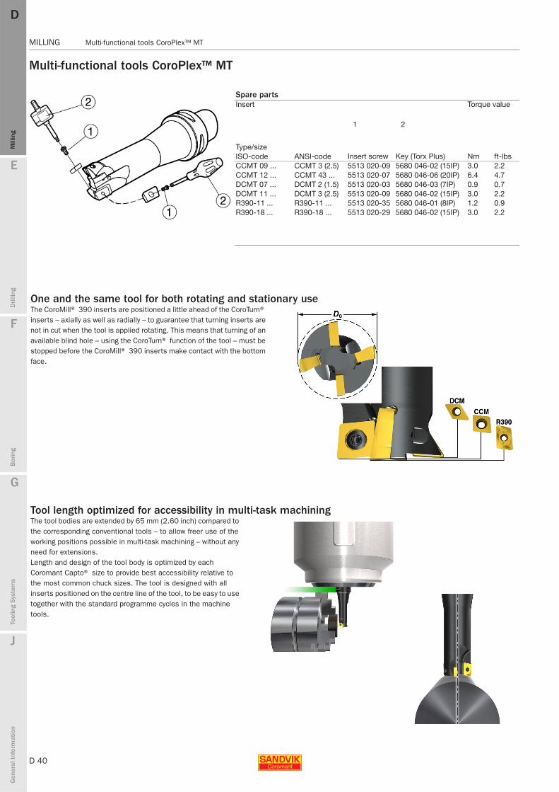
Spare partsInsert Torque value
Type/sizeInsert screw Key (Torx Plus) Nm ft-lbsISO-code ANSI-code
CCMT 09 ... CCMT 3 (2.5) 5513 020-09 5680 046-02 (15IP) 3.0 2.2CCMT 12 ... CCMT 43 ... 5513 020-07 5680 046-06 (20IP) 6.4 4.7DCMT 07 ... DCMT 2 (1.5) 5513 020-03 5680 046-03 (7IP) 0.9 0.7DCMT 11 ... DCMT 3 (2.5) 5513 020-09 5680 046-02 (15IP) 3.0 2.2R390-11 ... R390-11 ... 5513 020-35 5680 046-01 (8IP) 1.2 0.9R390-18 ... R390-18 ... 5513 020-29 5680 046-02 (15IP) 3.0 2.2
One and the same tool for both rotating and stationary useThe CoroMill® 390 inserts are positioned a little ahead of the CoroTurn® inserts – axially as well as radially – to guarantee that turning inserts are not in cut when the tool is applied rotating. This means that turning of an available blind hole – using the CoroTurn® function of the tool – must be stopped before the CoroMill® 390 inserts make contact with the bottom face.
Tool length optimized for accessibility in multi-task machiningThe tool bodies are extended by 65 mm (2.60 inch) compared to the corresponding conventional tools – to allow freer use of the working positions possible in multi-task machining – without any need for extensions.Length and design of the tool body is optimized by each Coromant Capto® size to provide best accessibility relative to the most common chuck sizes. The tool is designed with all inserts positioned on the centre line of the tool, to be easy to use together with the standard programme cycles in the machine tools.

E
D 41
Mill
ing
Drilli
ng
F
Bor
ing
G
Tool
ing
Syst
ems
J
Gen
eral
Info
rmat
ion
DD
Mill
ing
CoroMill® 390 MILLING
MILLING CoroMill® 390
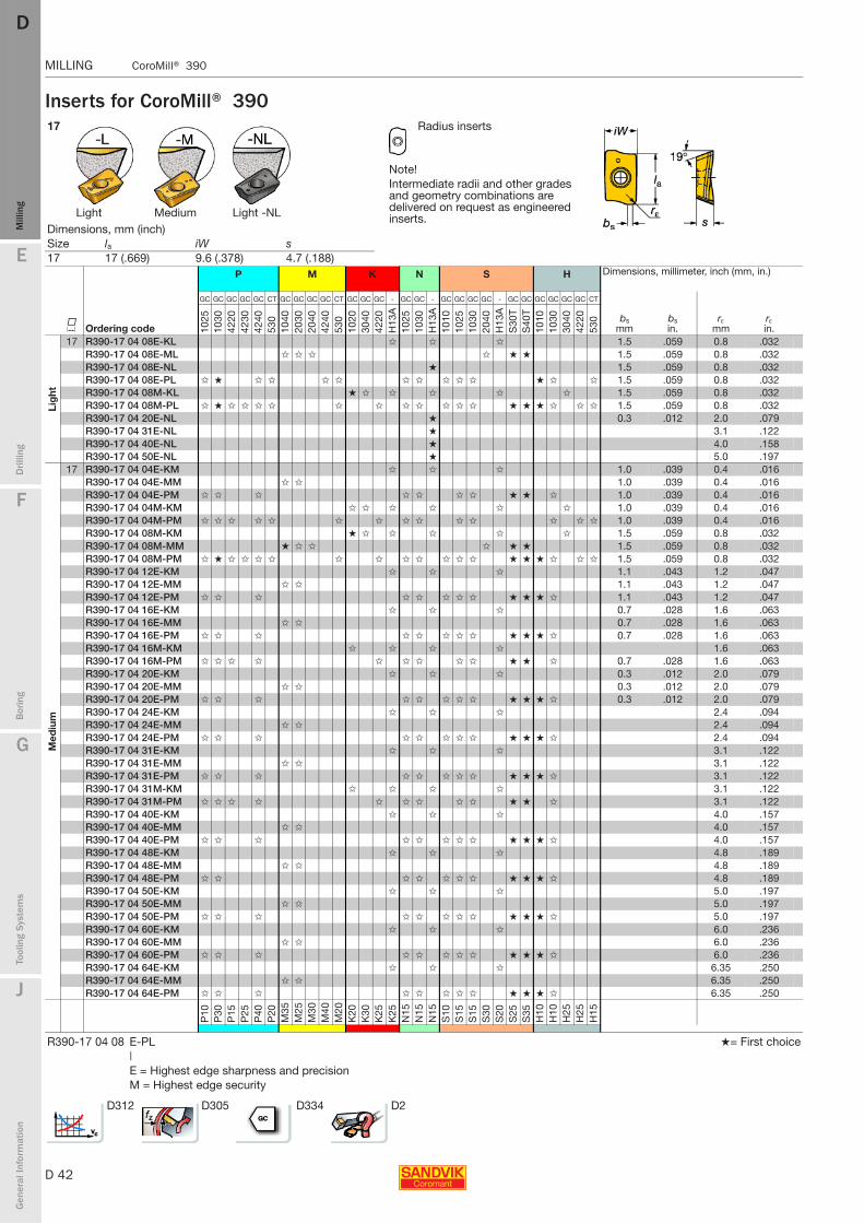
Inserts for CoroMill® 390
11 Radius inserts
Note!Intermediate radii and other grades and geometry combinations are delivered on request as engineered inserts.Light Medium Heavy Light -NL Diamond
Dimensions, mm (inch)Size la iW s 11 11 (.433) 6.8 (.268) 3.5 (.141)
P M K N S H Dimensions, millimeter, inch (mm, in.)
K Ordering code
GC GC GC GC GC CT GC GC GC CT GC GC GC - GC GC CT - GC GC GC GC - GC GC GC GC GC CT
bsmm
bsin.
rεmm
rεin.10
2510
3042
2042
3042
4053
010
4020
3020
4053
010
2030
4042
20H
13A
1025
1030
530
H13
A10
1010
2510
3020
40H
13A
S30
TS
40T
1010
3040
4220
530
Lig
ht
11 R390-11 T3 04E-NL ✩ 0.9 .035 0.4 .016R390-11 T3 04E-PL ✩ ✩ ✩ ✩ ✩ ✩ ★ ★ 0.9 .035 0.4 .016R390-11 T3 08E-KL ✩ ✩ ✩ 1.5 .059 0.8 .032R390-11 T3 08E-ML ★ ✩ ✩ ✩ ★ ★ 1.5 .059 0.8 .032R390-11 T3 08E-NL ★ 1.5 .059 0.8 .032R390-11 T3 08E-PL ✩ ★ ✩ ✩ ✩ ✩ ✩ ✩ ✩ ★ ✩ 1.5 .059 0.8 .032R390-11 T3 08M-KL ★ ✩ ✩ ✩ ✩ ★ 1.2 .047 0.8 .032R390-11 T3 08M-PL ✩ ★ ✩ ✩ ✩ ✩ ✩ ✩ ✩ ✩ ✩ ✩ ✩ ★ ★ ★ ✩ ✩ 1.2 .047 0.8 .032R390-11 T3 16E-ML ✩ ✩ ✩ ✩ ★ ★ 0.8 .032 1.6 .063R390-11 T3 20E-NL ✩ 2.0 .079R390-11 T3 24E-ML ✩ ✩ ✩ ✩ ★ ★ 2.4 .094R390-11 T3 31E-ML ✩ ✩ ✩ ✩ ★ ★ 3.1 .122R390-11 T3 31E-NL ✩ 3.1 .122
Med
ium
11 R390-11 T3 02E-KM ✩ ✩ ✩ 0.7 .028 0.2 .008R390-11 T3 02E-MM ✩ ✩ 0.7 .028 0.2 .008R390-11 T3 02E-PM ✩ ✩ ✩ ✩ ✩ ✩ ✩ 0.7 .028 0.2 .008R390-11 T3 04M-KM ✩ ✩ ✩ ✩ ✩ ✩ 0.9 .035 0.4 .016R390-11 T3 04M-PM ✩ ✩ ✩ ✩ ✩ ✩ ✩ ✩ ✩ ✩ ✩ ✩ 0.9 .035 0.4 .016R390-11 T3 08M-KM ★ ✩ ✩ ✩ ✩ ✩ 1.2 .047 0.8 .032R390-11 T3 08M-MM ★ ✩ ✩ ✩ ★ ★ 1.2 .047 0.8 .032R390-11 T3 08M-PM ✩ ★ ✩ ✩ ✩ ✩ ✩ ✩ ✩ ✩ ✩ ✩ ✩ ★ ★ ★ ✩ ✩ 1.2 .047 0.8 .032R390-11 T3 12E-KM ✩ ✩ ✩ 0.8 .032 1.2 .047R390-11 T3 12E-MM ✩ ✩ 0.8 .032 1.2 .047R390-11 T3 12E-PM ✩ ✩ ✩ ✩ ✩ ✩ ✩ ✩ ★ ★ ★ 0.8 .032 1.2 .047R390-11 T3 16E-KM ✩ ✩ ✩ 0.8 .032 1.6 .063R390-11 T3 16E-MM ✩ ✩ 0.4 .016 1.6 .063R390-11 T3 16E-PM ✩ ✩ ✩ ✩ ✩ ✩ ✩ ✩ ★ 0.4 .016 1.6 .063R390-11 T3 16M-KM ✩ ✩ ✩ ✩ 0.4 .016 1.6 .063R390-11 T3 16M-PM ✩ ✩ ✩ ✩ ✩ ✩ ✩ ✩ ✩ ✩ ★ ★ ★ 0.4 .016 1.6 .063R390-11 T3 20E-KM ✩ ✩ ✩ 0.4 .016 2.0 .079R390-11 T3 20E-MM ✩ ✩ 2.0 .079R390-11 T3 20E-PM ✩ ✩ ✩ ✩ ✩ ✩ ✩ ✩ ★ ★ ★ 2.0 .079R390-11 T3 24E-KM ✩ ✩ ✩ 2.4 .094R390-11 T3 24E-MM ✩ ✩ 2.4 .094R390-11 T3 24E-PM ✩ ✩ ✩ ✩ ✩ ✩ ✩ 2.4 .094R390-11 T3 31E-KM ✩ ✩ ✩ 3.1 .122R390-11 T3 31E-MM ✩ ✩ 3.1 .122R390-11 T3 31E-PM ✩ ✩ ✩ ✩ ✩ ✩ ✩ ✩ ★ 3.1 .122R390-11 T3 31M-KM ✩ ✩ ✩ ✩ 3.1 .122R390-11 T3 31M-PM ✩ ✩ ✩ ✩ ✩ ✩ ✩ ✩ ✩ ✩ ★ ★ ★ 3.1 .122
Hea
vy
11 R390-11 T3 10M-KH ★ ✩ ✩ 1.02 .040 1.0 .039R390-11 T3 10M-MH ★ ✩ ✩ ✩ 1.02 .040 1.0 .039R390-11 T3 10M-PH ✩ ✩ ✩ ✩ ★ ✩ ★ ★ ✩ 1.02 .040 1.0 .039
P10
P30
P15
P25
P40
P20
M35
M25
M30
M20
K20
K30
K25
K25
N15
N15
N15
N15
S10
S15
S15
S30
S20
S25
S35
H10
H25
H25
H15
R390-11 T3 04 E-PL|E = Highest edge sharpness and precisionM = Highest edge security
D312 D305 D334 D2
D 42
MILLING CoroMill® 390
E
Mill
ing
Drilli
ng
F
Bor
ing
G
Tool
ing
Syst
ems
J
Gen
eral
Info
rmat
ion
DDM
illin
g
MILLING CoroMill® 390
Inserts for CoroMill® 39017 Radius inserts
Note!Intermediate radii and other grades and geometry combinations are delivered on request as engineered inserts.Light Medium Light -NL
P M K N S H Dimensions, millimeter, inch (mm, in.)
K Ordering code
GC GC GC GC GC CT GC GC GC GC CT GC GC GC - GC GC - GC GC GC GC - GC GC GC GC GC GC CT
bsmm
bsin.
rεmm
rεin.10
2510
3042
2042
3042
4053
010
4020
3020
4042
4053
010
2030
4042
20H
13A
1025
1030
H13
A10
1010
2510
3020
40H
13A
S30
TS
40T
1010
1030
3040
4220
530
Lig
ht
17 R390-17 04 08E-KL ✩ ✩ ✩ 1.5 .059 0.8 .032R390-17 04 08E-ML ✩ ✩ ✩ ✩ ★ ★ 1.5 .059 0.8 .032R390-17 04 08E-NL ★ 1.5 .059 0.8 .032R390-17 04 08E-PL ✩ ★ ✩ ✩ ✩ ✩ ✩ ✩ ✩ ✩ ✩ ★ ✩ ✩ 1.5 .059 0.8 .032R390-17 04 08M-KL ★ ✩ ✩ ✩ ✩ ✩ 1.5 .059 0.8 .032R390-17 04 08M-PL ✩ ★ ✩ ✩ ✩ ✩ ✩ ✩ ✩ ✩ ✩ ✩ ✩ ★ ★ ★ ✩ ✩ ✩ 1.5 .059 0.8 .032R390-17 04 20E-NL ★ 0.3 .012 2.0 .079R390-17 04 31E-NL ★ 3.1 .122R390-17 04 40E-NL ★ 4.0 .158R390-17 04 50E-NL ★ 5.0 .197
Med
ium
17 R390-17 04 04E-KM ✩ ✩ ✩ 1.0 .039 0.4 .016R390-17 04 04E-MM ✩ ✩ 1.0 .039 0.4 .016R390-17 04 04E-PM ✩ ✩ ✩ ✩ ✩ ✩ ✩ ★ ★ ✩ 1.0 .039 0.4 .016R390-17 04 04M-KM ✩ ✩ ✩ ✩ ✩ ✩ 1.0 .039 0.4 .016R390-17 04 04M-PM ✩ ✩ ✩ ✩ ✩ ✩ ✩ ✩ ✩ ✩ ✩ ✩ ✩ ✩ 1.0 .039 0.4 .016R390-17 04 08M-KM ★ ✩ ✩ ✩ ✩ ✩ 1.5 .059 0.8 .032R390-17 04 08M-MM ★ ✩ ✩ ✩ ★ ★ 1.5 .059 0.8 .032R390-17 04 08M-PM ✩ ★ ✩ ✩ ✩ ✩ ✩ ✩ ✩ ✩ ✩ ✩ ✩ ★ ★ ★ ✩ ✩ ✩ 1.5 .059 0.8 .032R390-17 04 12E-KM ✩ ✩ ✩ 1.1 .043 1.2 .047R390-17 04 12E-MM ✩ ✩ 1.1 .043 1.2 .047R390-17 04 12E-PM ✩ ✩ ✩ ✩ ✩ ✩ ✩ ✩ ★ ★ ★ ✩ 1.1 .043 1.2 .047R390-17 04 16E-KM ✩ ✩ ✩ 0.7 .028 1.6 .063R390-17 04 16E-MM ✩ ✩ 0.7 .028 1.6 .063R390-17 04 16E-PM ✩ ✩ ✩ ✩ ✩ ✩ ✩ ✩ ★ ★ ★ ✩ 0.7 .028 1.6 .063R390-17 04 16M-KM ✩ ✩ ✩ ✩ 1.6 .063R390-17 04 16M-PM ✩ ✩ ✩ ✩ ✩ ✩ ✩ ✩ ✩ ★ ★ ✩ 0.7 .028 1.6 .063R390-17 04 20E-KM ✩ ✩ ✩ 0.3 .012 2.0 .079R390-17 04 20E-MM ✩ ✩ 0.3 .012 2.0 .079R390-17 04 20E-PM ✩ ✩ ✩ ✩ ✩ ✩ ✩ ✩ ★ ★ ★ ✩ 0.3 .012 2.0 .079R390-17 04 24E-KM ✩ ✩ ✩ 2.4 .094R390-17 04 24E-MM ✩ ✩ 2.4 .094R390-17 04 24E-PM ✩ ✩ ✩ ✩ ✩ ✩ ✩ ✩ ★ ★ ★ ✩ 2.4 .094R390-17 04 31E-KM ✩ ✩ ✩ 3.1 .122R390-17 04 31E-MM ✩ ✩ 3.1 .122R390-17 04 31E-PM ✩ ✩ ✩ ✩ ✩ ✩ ✩ ✩ ★ ★ ★ ✩ 3.1 .122R390-17 04 31M-KM ✩ ✩ ✩ ✩ 3.1 .122R390-17 04 31M-PM ✩ ✩ ✩ ✩ ✩ ✩ ✩ ✩ ✩ ★ ★ ✩ 3.1 .122R390-17 04 40E-KM ✩ ✩ ✩ 4.0 .157R390-17 04 40E-MM ✩ ✩ 4.0 .157R390-17 04 40E-PM ✩ ✩ ✩ ✩ ✩ ✩ ✩ ✩ ★ ★ ★ ✩ 4.0 .157R390-17 04 48E-KM ✩ ✩ ✩ 4.8 .189R390-17 04 48E-MM ✩ ✩ 4.8 .189R390-17 04 48E-PM ✩ ✩ ✩ ✩ ✩ ✩ ✩ ★ ★ ★ ✩ 4.8 .189R390-17 04 50E-KM ✩ ✩ ✩ 5.0 .197R390-17 04 50E-MM ✩ ✩ 5.0 .197R390-17 04 50E-PM ✩ ✩ ✩ ✩ ✩ ✩ ✩ ✩ ★ ★ ★ ✩ 5.0 .197R390-17 04 60E-KM ✩ ✩ ✩ 6.0 .236R390-17 04 60E-MM ✩ ✩ 6.0 .236R390-17 04 60E-PM ✩ ✩ ✩ ✩ ✩ ✩ ✩ ✩ ★ ★ ★ ✩ 6.0 .236R390-17 04 64E-KM ✩ ✩ ✩ 6.35 .250R390-17 04 64E-MM ✩ ✩ 6.35 .250R390-17 04 64E-PM ✩ ✩ ✩ ✩ ✩ ✩ ✩ ✩ ★ ★ ★ ✩ 6.35 .250
P10
P30
P15
P25
P40
P20
M35
M25
M30
M40
M20
K20
K30
K25
K25
N15
N15
N15
S10
S15
S15
S30
S20
S25
S35
H10
H10
H25
H25
H15
R390-17 04 08 E-PL ★= First choice|E = Highest edge sharpness and precisionM = Highest edge security
D312 D305 D334 D2
Dimensions, mm (inch)Size la iW s 17 17 (.669) 9.6 (.378) 4.7 (.188)

E
D 43
Mill
ing
Drilli
ng
F
Bor
ing
G
Tool
ing
Syst
ems
J
Gen
eral
Info
rmat
ion
DD
Mill
ing
CoroMill® 390 MILLING
MILLING CoroMill® 390
Inserts for CoroMill® 390
Advanced cutting materials
17 Radius inserts
Note!Intermediate radii and other grades and geometry combinations are delivered on request as engineered inserts.Medium Diamond
P K H Dimensions, millimeter, inch (mm, in.)
K Ordering code
GC GC GC GC GC GC GC
lamm
lain.
iWmm
iWin.
smm
sin.
bsmm
bsin.
rεmm
rεin.42
2042
3042
4010
2030
4042
2042
20
Hea
vy
17 R390-17 04 08M-KH ✩ ✩ 17 .669 9.6 .378 4.76 .188 1.5 .059 0.8 .032R390-17 04 08M-PH ✩ ★ ✩ ✩ 17 .669 9.6 .378 4.76 .188 1.5 .059 0.8 .032R390-17 04 16M-PH ✩ ✩ 17 .669 9.6 .378 4.76 .188 1.5 .059 1.6 .063
P15
P25
P40
K20
K30
K25
H25
N Dimensions, millimeter, inch (mm, in.)
K Ordering code
CD
lamm
lain.
iWmm
iWin.
smm
sin.
bsmm
bsin.
rεmm
rεin.C
D10
Lig
ht
11 R390-11T304E-P4-NL ✩ 11 .433 6.8 .268 3.59 .141 2.2 .087 0.4 .01617 R390-170408E-P6-NL ★ 17 .669 9.6 .378 4.76 .188 1.8 .071 0.8 .032
N05
D312 D305 D334 D2
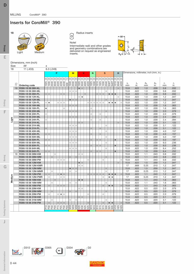
D 44
MILLING CoroMill® 390
E
Mill
ing
Drilli
ng
F
Bor
ing
G
Tool
ing
Syst
ems
J
Gen
eral
Info
rmat
ion
DDM
illin
g
MILLING CoroMill® 390
Inserts for CoroMill® 390
18 Radius inserts
Note!Intermediate radii and other grades and geometry combinations are delivered on request as engineered inserts.Light Medium
Dimensions, mm (inch)Size iW s 18 11 (.433) 6.3 (.249)
P M K N S H Dimensions, millimeter, inch (mm, in.)
K Ordering code
GC GC GC GC GC GC GC CT GC GC GC GC GC GC GC GC GC GC GC GC GC GC GC GC GC GC
lamm
lain.
bsmm
bsin.
rεmm
rεin.10
2510
3020
4030
4042
2042
3042
4053
010
4020
3020
4010
2030
4040
2042
2010
2510
3010
1010
2510
3020
40S
30T
S40
T10
1030
4042
20
Lig
ht
18 R390-18 06 08H-KL ★ ✩ ✩ 15.8 .622 1.0 .039 0.8 .032R390-18 06 08H-ML ✩ ✩ ✩ ✩ 15.8 .622 1.0 .039 0.8 .032R390-18 06 08H-PL ✩ ✩ ✩ ✩ ✩ ✩ ✩ ✩ ★ ★ ★ 15.8 .622 1.0 .039 0.8 .032R390-18 06 12H-KL ✩ ★ ✩ 15.8 .622 1.0 .039 1.2 .047R390-18 06 12H-ML ★ ✩ ✩ ✩ 15.8 .622 1.0 .039 1.2 .047R390-18 06 12H-PL ✩ ★ ✩ ✩ ✩ ✩ ✩ ✩ ✩ ✩ ✩ ★ ★ ★ ✩ 15.8 .622 1.0 .039 1.2 .047R390-18 06 16H-ML ✩ ✩ ✩ 15.8 .622 1.0 .039 1.6 .063R390-18 06 16H-PL ★ ✩ ✩ 15.8 .622 1.0 .039 1.6 .063R390-18 06 20H-ML ✩ ✩ ✩ ✩ 15.8 .622 1.0 .039 2.0 .079R390-18 06 20H-PL ✩ ✩ ✩ 15.8 .622 1.0 .039 2.0 .079R390-18 06 24H-ML ✩ ✩ ✩ ✩ 15.8 .622 1.0 .039 2.4 .094R390-18 06 24H-PL ✩ ✩ ✩ 15.8 .622 1.0 .039 2.4 .094R390-18 06 31H-KL ✩ ✩ ✩ 15.8 .622 1.0 .039 3.1 .122R390-18 06 31H-ML ✩ ✩ ✩ ✩ 15.8 .622 1.0 .039 3.1 .122R390-18 06 31H-PL ✩ ✩ ✩ 15.8 .622 1.0 .039 3.1 .122R390-18 06 40H-ML ✩ ✩ ✩ ✩ 15.8 .622 1.0 .039 4.0 .157R390-18 06 40H-PL ✩ ✩ ✩ ✩ 15.8 .622 1.0 .039 4.0 .157R390-18 06 50H-ML ✩ ✩ ✩ ✩ 15.8 .622 1.0 .039 5.0 .197R390-18 06 50H-PL ✩ ✩ ✩ ✩ ✩ ★ 15.8 .622 1.0 .039 5.0 .197R390-18 06 60H-ML ✩ ✩ ✩ ✩ 15.8 .622 1.0 .039 6.0 .236R390-18 06 60H-PL ✩ ✩ ✩ ✩ ✩ ★ 15.8 .622 1.0 .039 6.0 .236R390-18 06 64H-ML ✩ ✩ ✩ ✩ 15.8 .622 1.0 .039 6.4 .252R390-18 06 64H-PL ✩ ✩ ✩ ✩ ✩ ★ 15.8 .622 1.0 .039 6.4 .252
Med
ium
18 R390-18 06 08M-KM ✩ ✩ ✩ 15.8 .622 1.1 .043 0.8 .032R390-18 06 08M-MM ✩ ✩ ✩ ✩ 15.8 .622 1.1 .043 0.8 .032R390-18 06 08M-PM ✩ ✩ ✩ ✩ ✩ ✩ 15.8 .622 1.1 .043 0.8 .032R390-18 06 12M-KM ★ ✩ ✩ 15.8 .622 1.5 .059 1.2 .047R390-18 06 12M-KMR ✩ ✩ 17 .669 0.25 .010 1.2 .047R390-18 06 12M-MM ★ ✩ ✩ ✩ 15.8 .622 1.5 .059 1.2 .047R390-18 06 12M-MMR ✩ ✩ ✩ ✩ 17 .669 0.25 .010 1.2 .047R390-18 06 12M-PM ✩ ✩ ✩ ★ ✩ ✩ ✩ ✩ ✩ ✩ ✩ ★ ★ ★ ✩ 15.8 .622 1.1 .043 1.2 .047R390-18 06 12M-PMR ✩ ✩ ✩ ✩ ★ ★ 17 .669 0.25 .010 1.2 .047R390-18 06 16M-KM ✩ ★ ★ 15.8 .622 1.1 .043 1.6 .063R390-18 06 16M-MM ✩ ✩ ✩ ✩ 15.8 .622 1.1 .043 1.6 .063R390-18 06 16M-PM ✩ ✩ ✩ ✩ ✩ ✩ ★ ★ ✩ 15.8 .622 1.1 .043 1.6 .063R390-18 06 20M-KM ✩ ✩ 15.8 .622 0.5 .020 2.0 .079R390-18 06 20M-MM ✩ ✩ ✩ ✩ 15.8 .622 0.5 .020 2.0 .079R390-18 06 20M-PM ✩ ✩ ★ ✩ ✩ ✩ 15.8 .622 0.5 .020 2.0 .079R390-18 06 31M-KM ✩ ✩ 15.8 .622 0.5 .020 3.1 .122R390-18 06 31M-MM ✩ ✩ ✩ ✩ 15.8 .622 0.5 .020 3.1 .122R390-18 06 31M-PM ✩ ✩ ✩ ✩ ✩ ✩ ★ ★ ✩ 15.8 .622 0.5 .020 3.1 .122
P10
P30
P40
P20
P15
P25
P40
P20
M35
M25
M30
K20
K30
K25
K25
N15
N15
S10
S15
S15
S30
S25
S35
H10
H25
H25
D312 D305 D334 D2
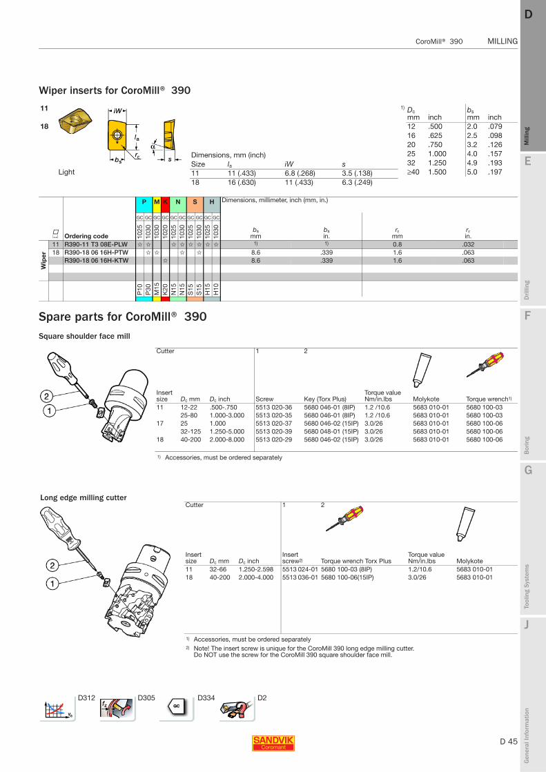
E
D 45
Mill
ing
Drilli
ng
F
Bor
ing
G
Tool
ing
Syst
ems
J
Gen
eral
Info
rmat
ion
DD
Mill
ing
CoroMill® 390 MILLING
MILLING CoroMill® 390
Dimensions, mm (inch)Size la iW s 11 11 (.433) 6.8 (.268) 3.5 (.138)18 16 (.630) 11 (.433) 6.3 (.249)
Wiper inserts for CoroMill® 390
Spare parts for CoroMill® 390Square shoulder face mill
11 1) Dc mm inch
bs mm inch
18 12 .500 2.0 .07916 .625 2.5 .09820 .750 3.2 .12625 1.000 4.0 .15732 1.250 4.9 .193
Light ≥40 1.500 5.0 .197
P M K N S H Dimensions, millimeter, inch (mm, in.)
K Ordering code
GC GC GC GC GC GC GC GC GC GC
bsmm
bsin.
rεmm
rεin.10
2510
3010
3010
2010
2510
3010
2510
3010
2510
30
Wip
er
11 R390-11 T3 08E-PLW ✩ ✩ ✩ ✩ ✩ ✩ ✩ ✩ 1) 1) 0.8 .03218 R390-18 06 16H-PTW ✩ ✩ ✩ ✩ 8.6 .339 1.6 .063
R390-18 06 16H-KTW ✩ 8.6 .339 1.6 .063
P10
P30
M15
K20
N15
N15
S15
S15
H15
H10
Cutter 1 2
Insert size Dc mm Dc inch Screw Key (Torx Plus)
Torque value Nm/in.lbs Molykote Torque wrench1)
11 12-22 .500-.750 5513 020-36 5680 046-01 (8IP) 1.2 /10.6 5683 010-01 5680 100-0325-80 1.000-3.000 5513 020-35 5680 046-01 (8IP) 1.2 /10.6 5683 010-01 5680 100-03
17 25 1.000 5513 020-37 5680 046-02 (15IP) 3.0/26 5683 010-01 5680 100-0632-125 1.250-5.000 5513 020-39 5680 048-01 (15IP) 3.0/26 5683 010-01 5680 100-06
18 40-200 2.000-8.000 5513 020-29 5680 046-02 (15IP) 3.0/26 5683 010-01 5680 100-06
1) Accessories, must be ordered separately
Long edge milling cutterCutter 1 2
Insert size Dc mm Dc inch
Insert screw2) Torque wrench Torx Plus
Torque value Nm/in.lbs Molykote
11 32-66 1.250-2.598 5513 024-01 5680 100-03 (8IP) 1.2/10.6 5683 010-0118 40-200 2.000-4.000 5513 036-01 5680 100-06(15IP) 3.0/26 5683 010-01
1) Accessories, must be ordered separately 2) Note! The insert screw is unique for the CoroMill 390 long edge milling cutter.
Do NOT use the screw for the CoroMill 390 square shoulder face mill.
D312 D305 D334 D2

D 46
MILLING CoroMill® 290
E
Mill
ing
Drilli
ng
F
Bor
ing
G
Tool
ing
Syst
ems
J
Gen
eral
Info
rmat
ion
DDM
illin
g
MILLING CoroMill® 290
CoroMill® 290 General purpose square shoulder milling cutter
Optional face mill generating low axial pressure
Diameter 40 - 250 mm (2.000 - 10.000 inch)High accuracy
Milling of 90° corners, capable of producing excellent surface quality.
Ceramic and boron nitride
Low axial forces
Pitch:
Condition:Unstable General Stable
Geometries:
General
Feed range
0.05 (.002) 0.30 (.012)
Tool options designed to individual customer requirements are available. For information on our Tailor Made programme see page J3.
ISO application areas:
Max. ap 10.7 mm (.421 inch)
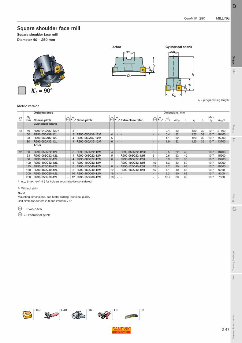
E
D 47
Mill
ing
Drilli
ng
F
Bor
ing
G
Tool
ing
Syst
ems
J
Gen
eral
Info
rmat
ion
DD
Mill
ing
CoroMill® 290 MILLING
MILLING CoroMill® 290
Square shoulder face millSquare shoulder face millDiameter 40 – 250 mm
Metric version
Arbor Cylindrical shank
l1 = programming length
Ordering code Dimensions, mm
KDc
mm Coarse pitch e i Close pitch e i Extra close pitch e i U dmm l1 l2 l3Max ap nmax1)
Cylindrical shank
12 40 R290-040A32-12L2) - 3 - - - - - - 0.4 32 120 39 10.7 2160050 R290-050A32-12L - 3 R290-050A32-12M 4 - - - - 0.4 32 120 39 10.7 1840063 R290-063A32-12L - 4 R290-063A32-12M 5 - - - - 1.1 32 120 39 10.7 1590080 R290-080A32-12L - 4 R290-080A32-12M 6 - - - - 1.9 32 120 39 10.7 13700
Arbor
12 50 R290-050Q22-12L - 3 R290-050Q22-12M 4 - R290-050Q22-12H2) 5 - 0.5 22 40 10.7 1840063 R290-063Q22-12L - 4 R290-063Q22-12M 5 - R290-063Q22-12H 6 - 0.6 22 40 10.7 1590080 R290-080Q27-12L - 4 R290-080Q27-12M 6 - R290-080Q27-12H 8 - 0.9 27 50 10.7 13700
100 R290-100Q32-12L - 5 R290-100Q32-12M 7 - R290-100Q32-12H 10 - 1.3 32 50 10.7 12000125 R290-125Q40-12L - 6 R290-125Q40-12M 8 - R290-125Q40-12H 12 - 2.7 40 63 10.7 10600160 R290-160Q40-12L - 8 R290-160Q40-12M 12 - R290-160Q40-12H 15 - 4.1 40 63 10.7 9250200 R290-200Q60-12L - 10 R290-200Q60-12M 16 - - - - 6.2 60 63 10.7 8200250 R290-250Q60-12L - 12 R290-250Q60-12M 18 - - - - 10.7 60 63 10.7 7300
1) nmax (max. rev/min) for holders must also be considered.
2) Without shim
Note!Mounting dimensions, see Metal cutting Technical guide.Bolt circle for cutters 200 and 250mm = 4"
e = Even pitch
i = Differential pitch
D49 D48 G6 D2 J3
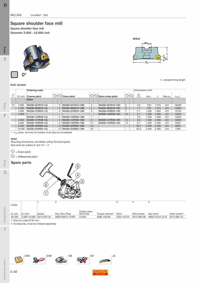
D 48
MILLING CoroMill® 290
E
Mill
ing
Drilli
ng
F
Bor
ing
G
Tool
ing
Syst
ems
J
Gen
eral
Info
rmat
ion
DDM
illin
g
MILLING CoroMill® 290
Square shoulder face millSquare shoulder face millDiameter 2.000 - 10.000 inch
Inch version
Arbor
l1 = programming length
Ordering code Dimensions, inch
K Dc inch Coarse pitch e i Close pitch e i Extra close pitch e i V dmm l1 Max ap nmax1)
Arbor
12 2.000 RA290-051R19-12L - 3 RA290-051R19-12M 4 - RA290-051R19-12H 5 - 0.8 .750 1.575 .421 184002.500 RA290-063R19-12L - 4 RA290-063R19-12M 5 - RA290-063R19-12H 6 - 1.1 .750 1.575 .421 159003.000 RA290-076R25-12L - 4 RA290-076R25-12M 6 - RA290-076R25-12H 7 - 2.1 1.000 1.969 .421 137004.000 - - - - - - RA290-102R38-12H 10 - 3.1 1.500 1.969 .421 12000
RA290-102R38-12L - 5 RA290-102R38-12M 7 - - - - 3.0 1.500 1.969 .421 120005.000 RA290-127R38-12L - 6 RA290-127R38-12M 8 - RA290-127R38-12H 12 - 6.0 1.500 2.480 .421 106006.000 RA290-152R38-12L - 8 RA290-152R38-12M 12 - RA290-152R38-12H 14 - 8.7 1.500 2.480 .421 92508.000 RA290-203R63-12L - 10 RA290-203R63-12M 16 - - - - 30.2 2.500 2.480 .421 8200
10.000 RA290-254R63-12L - 12 RA290-254R63-12M 18 - - - - 52.0 2.500 2.480 .421 73001) nmax (max. rev/min) for holders must also be considered.
Note!Mounting dimensions, see Metal cutting Technical guide.Bolt circle for cutters 8" and 10" = 4"
e = Even pitch
i = Differential pitch
Spare parts
Cutter1 2
Torque value Nm/in.lbs Torque wrench2)
3 4 5
Dc mm Dc Inch Screw Key (Torx Plus) Shim Shim screw Key (mm) Arbor screw1)
40-250 2.000-10.000 5513 020-32 5680 048-01 (15IP) 3.0/26 5680 100-06 5322 470-01 5512 090-09 5680 010-01 (3.5) 5512 060-151) Only for cutter Ø 50 mm.2) Accessories, must be ordered separately
D49 D48 G6 D2 J3
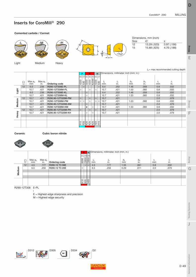
E
D 49
Mill
ing
Drilli
ng
F
Bor
ing
G
Tool
ing
Syst
ems
J
Gen
eral
Info
rmat
ion
DD
Mill
ing
CoroMill® 290 MILLING
MILLING CoroMill® 290
Inserts for CoroMill® 290
Cemented carbide / Cermet
Light Medium Heavy
la = max recommended cutting depth
P K H Dimensions, millimeter, inch (mm, in.)
JMax ap
mmMax ap
in. Ordering code
GC CT GC GC GC GC CT
lamm
lain.
bsmm
bsin.
rεmm
rεin.42
2053
032
2042
20K
20W
4220
530
Lig
ht
12 6.0 .236 R290-12T308E-PL ✩ ✩ 6.4 .252 1.46 .058 0.8 .03210.7 .421 R290-12T308M-PL ✩ ✩ ✩ 10.7 .421 1.53 .060 0.8 .0326.0 .236 R290-12T308E-KL ✩ 6.4 .252 1.46 .058 0.8 .032
10.7 .421 R290-12T308M-KL ✩ 10.7 .421 1.53 .060 0.8 .032
Med
ium 12 10.7 .421 R290.90-12T320M-PM ✩ ✩ ✩ 10.7 .421 2.0 .079
10.7 .421 R290-12T308M-PM ✩ ✩ ✩ ✩ ✩ 10.7 .421 1.53 .060 0.8 .03210.7 .421 R290.90-12T320M-KM ✩ 10.7 .421 2.0 .07910.7 .421 R290-12T308M-KM ★ ✩ 10.7 .421 1.53 .060 0.8 .032
Hea
vy
12 10.7 .421 R290.90-12T320M-PH ✩ ✩ ✩ 10.7 .421 2.0 .07910.7 .421 R290.90-12T320M-KH ✩ ✩ 10.7 .421 2.0 .079
P15
P20
K20
K25
K25
H25
H15
Ceramic Cubic boron nitride
K H Dimensions, millimeter, inch (mm, in.)
JMax ap
mmMax ap
in. Ordering code
CC CB CB
lamm
lain.
bsmm
bsin.
rεmm
rεin.60
90C
B50
CB
50
Med
ium
12 4.5 .177 R290-12 T3 08E ✩ ✩ 4.5 .177 1.55 .061 0.8 .0326.5 .256 R290-12 T3 20E ✩ 6.5 .256 0.29 .011 2.0 .079
K10
K05
H05
R290-12T308 E-PL|E = Highest edge sharpness and precisionM = Highest edge security
D312 D305 D334 D2
Dimensions, mm (inch)Size iC s 12 13.29 (.523) 3.97 (.156)15 15.88 (.625) 4.76 (.188)
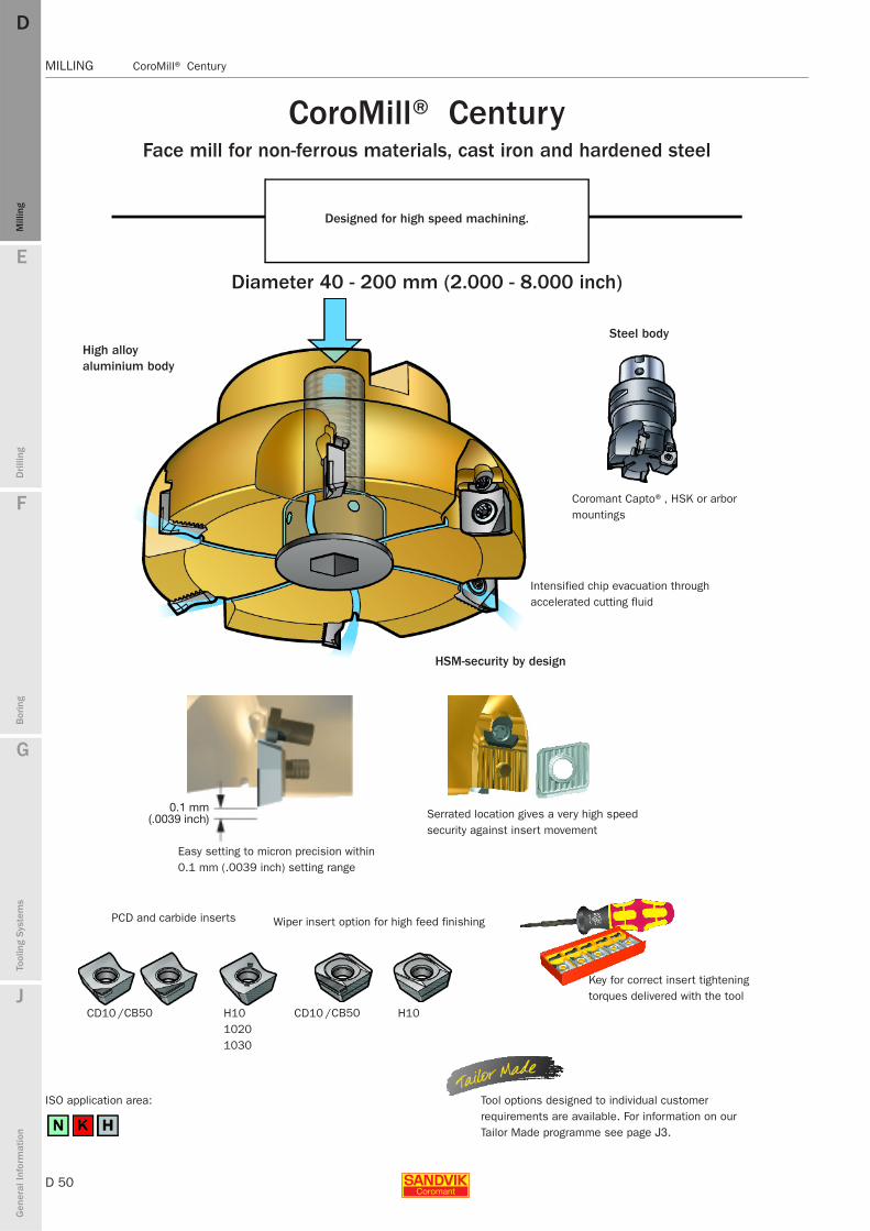
D 50
MILLING CoroMill® Century
E
Mill
ing
Drilli
ng
F
Bor
ing
G
Tool
ing
Syst
ems
J
Gen
eral
Info
rmat
ion
DDM
illin
g
MILLING CoroMill® Century
/CB50 /CB50
CoroMill® Century Face mill for non-ferrous materials, cast iron and hardened steel
Designed for high speed machining.
Diameter 40 - 200 mm (2.000 - 8.000 inch)
High alloy aluminium body
Easy setting to micron precision within 0.1 mm (.0039 inch) setting range
PCD and carbide inserts
CD10 H10 10201030
ISO application area:
Wiper insert option for high feed finishing
CD10 H10
Steel body
Coromant Capto®, HSK or arbor mountings
Intensified chip evacuation through accelerated cutting fluid
HSM-security by design
Serrated location gives a very high speed security against insert movement
Key for correct insert tightening torques delivered with the tool
Tool options designed to individual customer requirements are available. For information on our Tailor Made programme see page J3.
0.1 mm(.0039 inch)
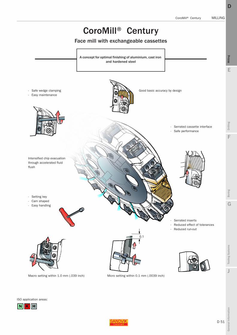
E
D 51
Mill
ing
Drilli
ng
F
Bor
ing
G
Tool
ing
Syst
ems
J
Gen
eral
Info
rmat
ion
DD
Mill
ing
CoroMill® Century MILLING
MILLING CoroMill® Century
CoroMill® Century Face mill with exchangeable cassettes
A concept for optimal finishing of aluminium, cast iron and hardened steel
- Safe wedge clamping- Easy maintenance
Intensified chip evacuation through accelerated fluid flush
- Setting key- Cam shaped- Easy handling
Macro setting within 1.0 mm (.039 inch)
ISO application areas:
Good basic accuracy by design
- Serrated cassette interface- Safe performance
- Serrated inserts- Reduced effect of tolerances- Reduced run-out
Micro setting within 0.1 mm (.0039 inch)
0.1
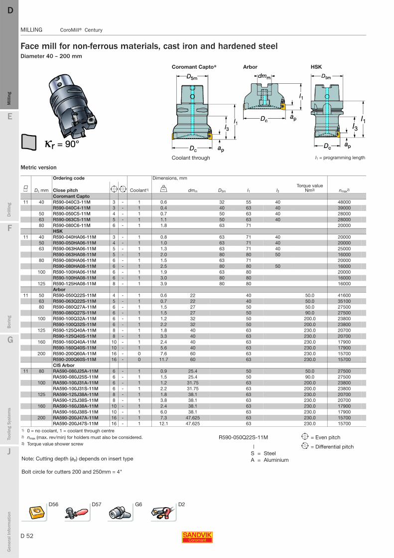
D 52
MILLING CoroMill® Century
E
Mill
ing
Drilli
ng
F
Bor
ing
G
Tool
ing
Syst
ems
J
Gen
eral
Info
rmat
ion
DDM
illin
g
MILLING CoroMill® Century
Face mill for non-ferrous materials, cast iron and hardened steelDiameter 40 – 200 mm
Metric version
Coromant Capto® Arbor HSK
Coolant through l1 = programming length
Ordering code Dimensions, mm
K Dc mm Close pitch e i Coolant1) U dmm D5m l1 l3Torque value
Nm3) nmax2)
Coromant Capto 11 40 R590-040C3-11M 3 - 1 0.6 32 55 40 48000
R590-040C4-11M 3 - 1 0.4 40 63 40 3900050 R590-050C5-11M 4 - 1 0.7 50 63 40 2800063 R590-063C5-11M 5 - 1 1.1 50 63 40 2800080 R590-080C6-11M 6 - 1 1.8 63 71 20000
HSK11 40 R590-040HA06-11M 3 - 1 0.8 63 71 40 20000
50 R590-050HA06-11M 4 - 1 1.0 63 71 40 2000063 R590-063HA06-11M 5 - 1 1.3 63 71 40 25000
R590-063HA08-11M 5 - 1 2.0 80 80 50 1600080 R590-080HA06-11M 6 - 1 1.5 63 71 20000
R590-080HA08-11M 6 - 1 2.5 80 80 50 16000100 R590-100HA06-11M 6 - 1 1.9 63 80 20000
R590-100HA08-11M 6 - 1 3.0 80 80 16000125 R590-125HA08-11M 8 - 1 3.9 80 80 16000
Arbor11 50 R590-050Q22S-11M 4 - 1 0.6 22 40 50.0 41600
63 R590-063Q22S-11M 5 - 1 0.7 22 40 50.0 3510080 R590-080Q27A-11M 6 - 1 1.5 27 50 50.0 27500
R590-080Q27S-11M 6 - 1 1.5 27 50 90.0 27500100 R590-100Q32A-11M 6 - 1 1.2 32 50 200.0 23800
R590-100Q32S-11M 6 - 1 2.2 32 50 200.0 23800125 R590-125Q40A-11M 8 - 1 1.8 40 63 230.0 20700
R590-125Q40S-11M 8 - 1 3.3 40 63 230.0 20700160 R590-160Q40A-11M 10 - 1 2.4 40 63 230.0 17900
R590-160Q40S-11M 10 - 1 5.6 40 63 230.0 17900200 R590-200Q60A-11M 16 - 0 7.6 60 63 230.0 15700
R590-200Q60S-11M 16 - 0 11.7 60 63 230.0 15700CIS Arbor
11 80 RA590-080J25A-11M 6 - 1 0.9 25.4 50 50.0 27500RA590-080J25S-11M 6 - 1 1.5 25.4 50 90.0 27500
100 RA590-100J31A-11M 6 - 1 1.2 31.75 63 200.0 23800RA590-100J31S-11M 6 - 1 2.2 31.75 63 200.0 23800
125 RA590-125J38A-11M 8 - 1 1.8 38.1 63 230.0 20700RA590-125J38S-11M 8 - 1 3.8 38.1 63 230.0 20700
160 RA590-160J38A-11M 10 - 1 2.4 38.1 63 230.0 17900RA590-160J38S-11M 10 - 1 6.0 38.1 63 230.0 17900
200 RA590-200J47A-11M 16 - 1 7.3 47.625 63 230.0 15700RA590-200J47S-11M 16 - 1 12.1 47.625 63 230.0 15700
1) 0 = no coolant, 1 = coolant through centre2) nmax (max. rev/min) for holders must also be considered.3) Torque value shower screw
Note: Cutting depth (ap) depends on insert type
Bolt circle for cutters 200 and 250mm = 4"
D56 D57 G6 D2
R590-050Q22S-11M e = Even pitch
| i = Differential pitchS = SteelA = Aluminium
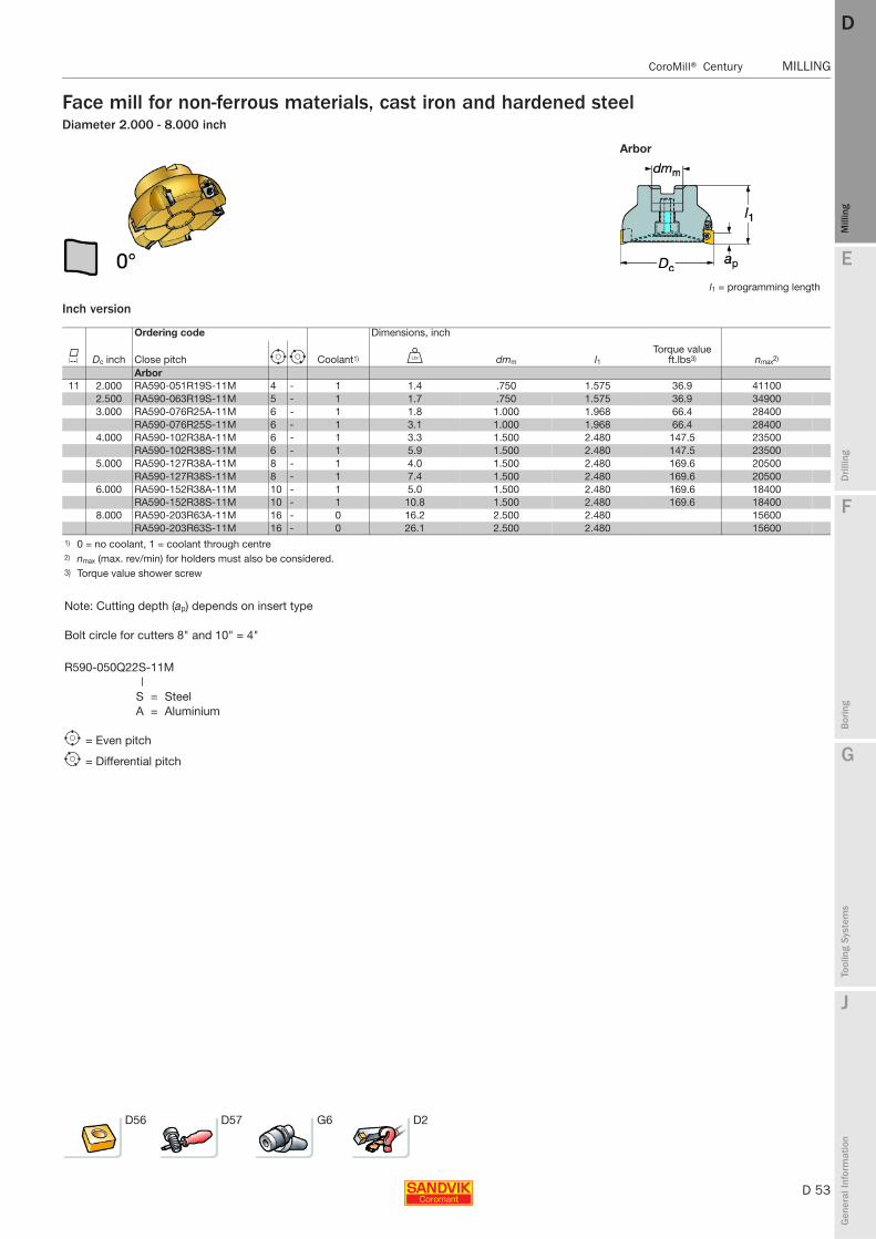
E
D 53
Mill
ing
Drilli
ng
F
Bor
ing
G
Tool
ing
Syst
ems
J
Gen
eral
Info
rmat
ion
DD
Mill
ing
CoroMill® Century MILLING
MILLING CoroMill® Century
Face mill for non-ferrous materials, cast iron and hardened steelDiameter 2.000 - 8.000 inch
Inch version
Arbor
l1 = programming length
Ordering code Dimensions, inch
K Dc inch Close pitch e i Coolant1) V dmm l1Torque value
ft.lbs3) nmax2)
Arbor11 2.000 RA590-051R19S-11M 4 - 1 1.4 .750 1.575 36.9 41100
2.500 RA590-063R19S-11M 5 - 1 1.7 .750 1.575 36.9 349003.000 RA590-076R25A-11M 6 - 1 1.8 1.000 1.968 66.4 28400
RA590-076R25S-11M 6 - 1 3.1 1.000 1.968 66.4 284004.000 RA590-102R38A-11M 6 - 1 3.3 1.500 2.480 147.5 23500
RA590-102R38S-11M 6 - 1 5.9 1.500 2.480 147.5 235005.000 RA590-127R38A-11M 8 - 1 4.0 1.500 2.480 169.6 20500
RA590-127R38S-11M 8 - 1 7.4 1.500 2.480 169.6 205006.000 RA590-152R38A-11M 10 - 1 5.0 1.500 2.480 169.6 18400
RA590-152R38S-11M 10 - 1 10.8 1.500 2.480 169.6 184008.000 RA590-203R63A-11M 16 - 0 16.2 2.500 2.480 15600
RA590-203R63S-11M 16 - 0 26.1 2.500 2.480 156001) 0 = no coolant, 1 = coolant through centre2) nmax (max. rev/min) for holders must also be considered.3) Torque value shower screw
Note: Cutting depth (ap) depends on insert type
Bolt circle for cutters 8" and 10" = 4"
R590-050Q22S-11M|
S = SteelA = Aluminium
e = Even pitch
i = Differential pitch
D56 D57 G6 D2

D 54
MILLING CoroMill® Century
E
Mill
ing
Drilli
ng
F
Bor
ing
G
Tool
ing
Syst
ems
J
Gen
eral
Info
rmat
ion
DDM
illin
g
MILLING CoroMill® Century
CoroMill® Century face millwith exchangeable cassette system for arbor mountingDiameter 160 - 500 mm
Metric version
TO BE QUOTED
l1 = programming length
K1)
Ordering code Dimensions Close pitch Close pitchEven Even
Dc mm Coolant through e No coolant through e U dmm l1 nmax2)
Metric versions - Steel body11 160 S-R/L590-160Q40CS1-11M 10 S-R/L590-160Q40CS0-11M 10 6.5 40 63 3166
200 S-R/L590-200Q60CS1-11M 12 S-R/L590-200Q60CS0-11M 12 9.5 60 63 2837250 S-R/L590-250Q60CS1-11M 16 S-R/L590-250Q60CS0-11M 16 15.0 60 63 2533315 S-R/L590-315Q60CS1-11M 20 S-R/L590-315Q60CS0-11M 20 25.0 60 80 2251400 S-R/L590-400Q60CS1-11M 26 S-R/L590-400Q60CS0-11M 26 42.0 60 80 1992500 S-R/L590-500Q60CS1-11M 32 S-R/L590-500Q60CS0-11M 32 60.0 60 80 1795
Metric versions – Aluminium 11 160 S-R/L590-160Q40CA1-11M 10 S-R/L590-160Q40CA0-11M 10 3.0 40 63 3166
200 S-R/L590-200Q40CA1-11M 12 S-R/L590-200Q40CA0-11M 12 8.0 60 63 2837250 S-R/L590-250Q60CA1-11M 16 S-R/L590-250Q60CA0-11M 16 10.0 60 63 2533315 S-R/L590-315Q60CA1-11M 20 S-R/L590-315Q60CA0-11M 20 12.0 60 80 2251400 S-R/L590-400Q60CA1-11M 26 S-R/L590-400Q60CA0-11M 26 16.0 60 80 1992500 S-R/L590-500Q60CA1-11M 32 S-R/L590-500Q60CA0-11M 32 20.0 60 80 1795
CIS Versions - Steel body11 160 S-R/LA590-160J38CS1-11M 10 S-R/LA590-160J38CS0-11M 10 6.5 38.1 63 3166
200 S-R/LA590-200J47CS1-11M 12 S-R/LA590-200J47CS0-11M 12 9.5 47.625 63 2837250 S-R/LA590-250J47CS1-11M 16 S-R/LA590-250J47CS0-11M 16 10.0 47.625 63 2533315 S-R/LA590-315J47CS1-11M 20 S-R/LA590-315J47CS0-11M 20 12.0 47.625 80 2251
CIS Versions - Aluminium body11 160 S-R/LA590-160J38CA1-11M 10 S-R/LA590-160J38CA0-11M 10 3.0 38.1 63 3166
200 S-R/LA590-200J47CA1-11M 12 S-R/LA590-200J47CA0-11M 12 8.0 47.625 63 2837250 S-R/LA590-250J47CA1-11M 16 S-R/LA590-250J47CA0-11M 16 10.0 47.625 63 2533315 S-R/LA590-315J47CA1-11M 20 S-R/LA590-315J47CA0-11M 20 12.0 47.625 80 2251
1) Inserts are ordered separately. Ordering example: 2 pieces S-R590-160Q40CS1-11M2) nmax (max. rev/min) for holders must also be considered. All those cutters are subject to quotation, please contact your
Sandvik Coromant representative.Note: Cutting depth ap depending of insert type.
D56 D57 G6 D2
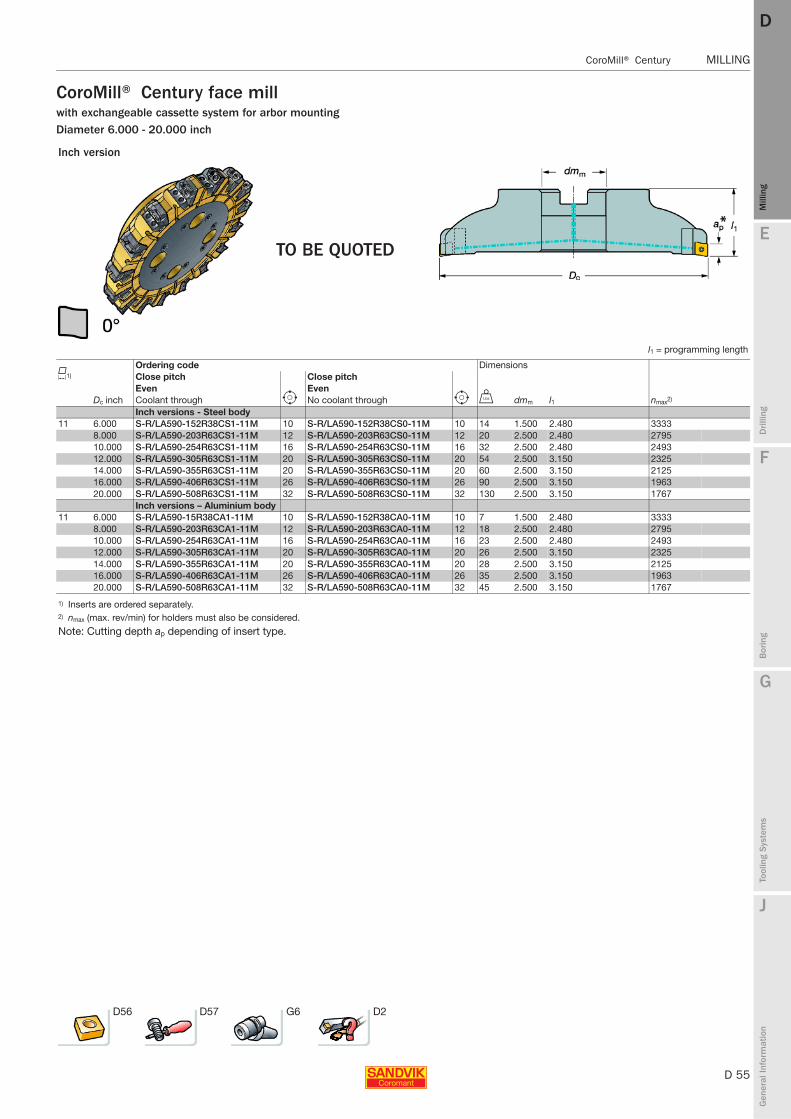
E
D 55
Mill
ing
Drilli
ng
F
Bor
ing
G
Tool
ing
Syst
ems
J
Gen
eral
Info
rmat
ion
DD
Mill
ing
CoroMill® Century MILLING
MILLING CoroMill® Century
CoroMill® Century face millwith exchangeable cassette system for arbor mountingDiameter 6.000 - 20.000 inch
Inch version
TO BE QUOTED
l1 = programming length
K1)
Ordering code Dimensions Close pitch Close pitchEven Even
Dc inch Coolant through e No coolant through e V dmm l1 nmax2)
Inch versions - Steel body11 6.000 S-R/LA590-152R38CS1-11M 10 S-R/LA590-152R38CS0-11M 10 14 1.500 2.480 3333
8.000 S-R/LA590-203R63CS1-11M 12 S-R/LA590-203R63CS0-11M 12 20 2.500 2.480 279510.000 S-R/LA590-254R63CS1-11M 16 S-R/LA590-254R63CS0-11M 16 32 2.500 2.480 249312.000 S-R/LA590-305R63CS1-11M 20 S-R/LA590-305R63CS0-11M 20 54 2.500 3.150 232514.000 S-R/LA590-355R63CS1-11M 20 S-R/LA590-355R63CS0-11M 20 60 2.500 3.150 212516.000 S-R/LA590-406R63CS1-11M 26 S-R/LA590-406R63CS0-11M 26 90 2.500 3.150 196320.000 S-R/LA590-508R63CS1-11M 32 S-R/LA590-508R63CS0-11M 32 130 2.500 3.150 1767
Inch versions – Aluminium body11 6.000 S-R/LA590-15R38CA1-11M 10 S-R/LA590-152R38CA0-11M 10 7 1.500 2.480 3333
8.000 S-R/LA590-203R63CA1-11M 12 S-R/LA590-203R63CA0-11M 12 18 2.500 2.480 279510.000 S-R/LA590-254R63CA1-11M 16 S-R/LA590-254R63CA0-11M 16 23 2.500 2.480 249312.000 S-R/LA590-305R63CA1-11M 20 S-R/LA590-305R63CA0-11M 20 26 2.500 3.150 232514.000 S-R/LA590-355R63CA1-11M 20 S-R/LA590-355R63CA0-11M 20 28 2.500 3.150 212516.000 S-R/LA590-406R63CA1-11M 26 S-R/LA590-406R63CA0-11M 26 35 2.500 3.150 196320.000 S-R/LA590-508R63CA1-11M 32 S-R/LA590-508R63CA0-11M 32 45 2.500 3.150 1767
1) Inserts are ordered separately.2) nmax (max. rev/min) for holders must also be considered.
Note: Cutting depth ap depending of insert type.
D56 D57 G6 D2
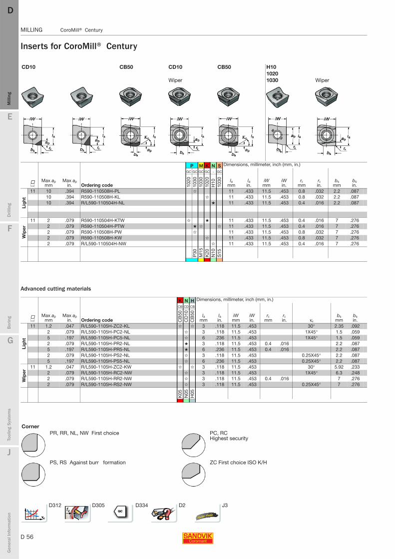
D 56
MILLING CoroMill® Century
E
Mill
ing
Drilli
ng
F
Bor
ing
G
Tool
ing
Syst
ems
J
Gen
eral
Info
rmat
ion
DDM
illin
g
MILLING CoroMill® Century
Inserts for CoroMill® Century
Advanced cutting materials
CD10 CB50 CD10 CB50 H101020
Wiper 1030 Wiper
P M K N S Dimensions, millimeter, inch (mm, in.)
KMax ap
mmMax ap
in. Ordering code
GC GC GC GC - GC
lamm
lain.
iWmm
iWin.
rεmm
rεin.
bsmm
bsin.10
2010
3010
3010
20H
1010
30
Lig
ht
11 10 .394 R590-110508H-PL ✩ 11 .433 11.5 .453 0.8 .032 2.2 .08710 .394 R590-110508H-KL ✩ 11 .433 11.5 .453 0.8 .032 2.2 .08710 .394 R/L590-110504H-NL ★ 11 .433 11.5 .453 0.4 .016 2.2 .087
Wip
er
11 2 .079 R590-110504H-KTW ✩ ★ 11 .433 11.5 .453 0.4 .016 7 .2762 .079 R590-110504H-PTW ★ ✩ ✩ 11 .433 11.5 .453 0.4 .016 7 .2762 .079 R590-110508H-PW ✩ 11 .433 11.5 .453 0.8 .032 7 .2762 .079 R590-110508H-KW ✩ 11 .433 11.5 .453 0.8 .032 7 .2762 .079 R/L590-110504H-NW ✩ 11 .433 11.5 .453 0.4 .016 7 .276
P30
M15
K20
N10
S15
K N H Dimensions, millimeter, inch (mm, in.)
KMax ap
mmMax ap
in. Ordering code
CB CD CB
lamm
lain.
iWmm
iWin.
rεmm
rεin. κε
bsmm
bsin.C
B50
CD
10C
B50
Lig
ht
11 1.2 .047 R/L590-1105H-ZC2-KL ✩ ✩ 3 .118 11.5 .453 30° 2.35 .0922 .079 R/L590-1105H-PC2-NL ✩ 3 .118 11.5 .453 1X45° 1.5 .0595 .197 R/L590-1105H-PC5-NL ✩ 6 .236 11.5 .453 1X45° 1.5 .0592 .079 R/L590-1105H-PR2-NL ★ 3 .118 11.5 .453 0.4 .016 2.2 .0875 .197 R/L590-1105H-PR5-NL ★ 6 .236 11.5 .453 0.4 .016 2.2 .0872 .079 R/L590-1105H-PS2-NL ✩ 3 .118 11.5 .453 0.25X45° 2.2 .0875 .197 R/L590-1105H-PS5-NL ✩ 6 .236 11.5 .453 0.25X45° 2.2 .087
Wip
er
11 1.2 .047 R/L590-1105H-ZC2-KW ✩ ✩ 3 .118 11.5 .453 30° 5.92 .2332 .079 R/L590-1105H-RC2-NW ✩ 3 .118 11.5 .453 1X45° 6.3 .2482 .079 R/L590-1105H-RR2-NW ✩ 3 .118 11.5 .453 0.4 .016 7 .2762 .079 R/L590-1105H-RS2-NW ✩ 3 .118 11.5 .453 0.25X45° 7 .276
K05
N05
H05
Corner PR, RR, NL, NW First choice PC, RC
Highest security
PS, RS Against burr formation ZC First choice ISO K/H
D312 D305 D334 D2 J3

E
D 57
Mill
ing
Drilli
ng
F
Bor
ing
G
Tool
ing
Syst
ems
J
Gen
eral
Info
rmat
ion
DD
Mill
ing
CoroMill® Century MILLING
MILLING CoroMill® Century
Spare parts for CoroMill® Century
Spare parts for cassettes
Spare parts for CoroMill® Century bodies
Axial setting of the CoroMill Century cutterInstructions for setting of CoroMill Century are included in each tool package.
Cutter 1 2 4 5
Dc mm Dc inch Insert screw Torque wrench (Torx Plus)Torque value Nm (ft-lbs) Setting device
Setting device screw
Coromant Capto® and HSK40– 125 1.575– 3.150 5513 020-25 5680 100-06 (15IP) 3.0 (2.2) 5513 014-021 5513 014-02Arbor50– 63 2.000– 2.500 5513 020-25 5680 100-06 (15IP) 3.0 (2.2) 5513 014-021 5513 014-02
80 3.000 5513 020-25 5680 100-06 (15IP) 3.0 (2.2) 5513 014-021 5513 014-02100 4.000 5513 020-25 5680 100-06 (15IP) 3.0 (2.2) 5513 014-021 5513 014-02125 5.000 5513 020-25 5680 100-06 (15IP) 3.0 (2.2) 5513 014-021 5513 014-02160 6.000 5513 020-25 5680 100-06 (15IP) 3.0 (2.2) 5513 014-021 5513 014-02200 8.000 5513 020-25 5680 100-06 (15IP) 3.0 (2.2) 5513 014-021 5513 014-02
1) See adaptor for face mills.
Cutter 3 Cutter 3
Dc mm Shower screw Key (Torx Plus) Dc inch Shower screw Key (Torx Plus) Torque value Nm (in-lbs)50-63 5512 087-01 5680 043-17 2.000-2.500 5512 088-01 5680 043-17 50 (36)80 5512 087-02 5680 043-18 3.000 5512 088-02 5680 043-18 90 (66)100 5512 087-03 5680 043-18 4.000 5512 088-03 5680 043-18 200 (147)1001) 5512 087-04 5680 043-18 5.000-6.000 5512 099-01 5680 043-18 230 (170)125-160 5512 098-01 5680 043-18 230 (170)1) CIS Arbor
Cutter Dc mm Edge guard Cutter Coolant tubes Key 40 91 100 HSK63 5692 020-04 5680 094-0450 91 101 HSK80 5692 020-05 5680 094-0563 91 10280 91 103100 91 104125 91 105160 91 106200 91 277
Cassette Insert screwTorque value Nm (in-lbs) Setting device Setting device screw Torque wrench Key
R/L 590-CA-11 5513 020-25 3.0 (26.55) 5513 014-021 5513 014-02 5680 100-06 (15IP) –
Dc mm (inch) Wedge Wedge screw Wedge key Eccentric key160-500 (6.000 - 20.000) 5431 105-03 339-831 265.2-817 (3.0) 5680 067-01
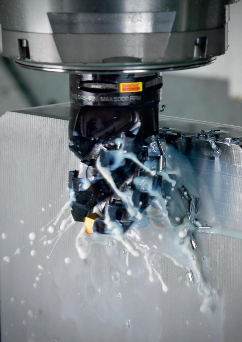
Rotating_Utfyllnadssidor.indd 1 2010-12-09 12:30:00
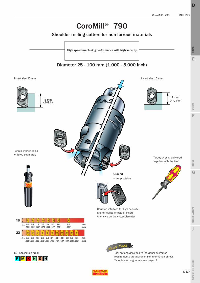
E
D 59
Mill
ing
Drilli
ng
F
Bor
ing
G
Tool
ing
Syst
ems
J
Gen
eral
Info
rmat
ion
DD
Mill
ing
CoroMill® 790 MILLING
MILLING CoroMill® 790
18 mm(.709 inch)
12 mm.472 inch
CoroMill® 790Shoulder milling cutters for non-ferrous materials
High speed machining performance with high security
Diameter 25 - 100 mm (1.000 - 5.000 inch)
Insert size 22 mm
Torque wrench to be ordered separately
Insert size 16 mm
Torque wrench delivered together with the tool
Ground
– for precision
Serrated interface for high security and to reduce effects of insert tolerance on the cutter diameter
Tool options designed to individual customer requirements are available. For information on our Tailor Made programme see page J3.
ISO application area:
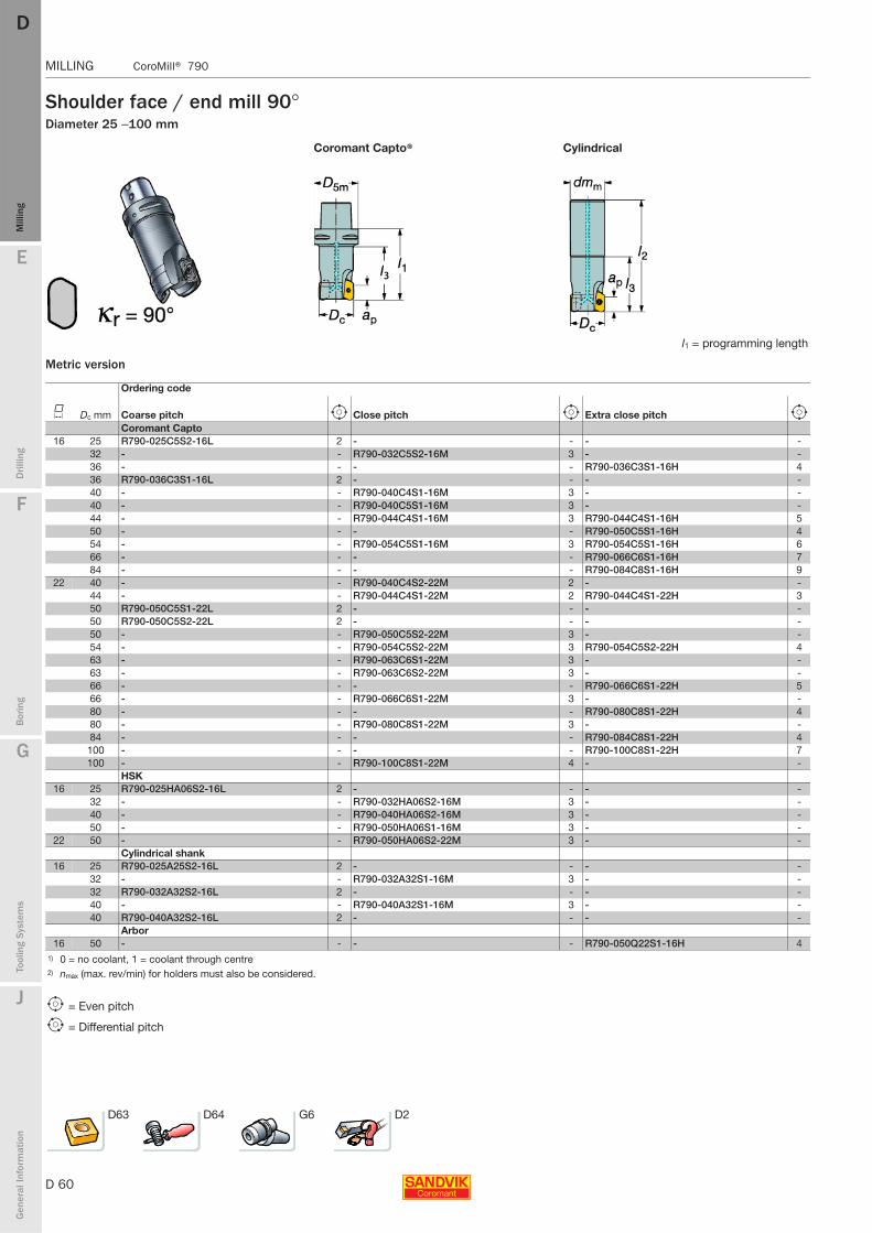
D 60
MILLING CoroMill® 790
E
Mill
ing
Drilli
ng
F
Bor
ing
G
Tool
ing
Syst
ems
J
Gen
eral
Info
rmat
ion
DDM
illin
g
MILLING CoroMill® 790
Shoulder face / end mill 90°Diameter 25 − 100 mm
Metric version
Coromant Capto® Cylindrical
l1 = programming length
Ordering code
K Dc mm Coarse pitch e Close pitch e Extra close pitch e
Coromant Capto 16 25 R790-025C5S2-16L 2 - - - -
32 - - R790-032C5S2-16M 3 - -36 - - - - R790-036C3S1-16H 436 R790-036C3S1-16L 2 - - - -40 - - R790-040C4S1-16M 3 - -40 - - R790-040C5S1-16M 3 - -44 - - R790-044C4S1-16M 3 R790-044C4S1-16H 550 - - - - R790-050C5S1-16H 454 - - R790-054C5S1-16M 3 R790-054C5S1-16H 666 - - - - R790-066C6S1-16H 784 - - - - R790-084C8S1-16H 9
22 40 - - R790-040C4S2-22M 2 - -44 - - R790-044C4S1-22M 2 R790-044C4S1-22H 350 R790-050C5S1-22L 2 - - - -50 R790-050C5S2-22L 2 - - - -50 - - R790-050C5S2-22M 3 - -54 - - R790-054C5S2-22M 3 R790-054C5S2-22H 463 - - R790-063C6S1-22M 3 - -63 - - R790-063C6S2-22M 3 - -66 - - - - R790-066C6S1-22H 566 - - R790-066C6S1-22M 3 - -80 - - - - R790-080C8S1-22H 480 - - R790-080C8S1-22M 3 - -84 - - - - R790-084C8S1-22H 4100 - - - - R790-100C8S1-22H 7100 - - R790-100C8S1-22M 4 - -
HSK16 25 R790-025HA06S2-16L 2 - - - -
32 - - R790-032HA06S2-16M 3 - -40 - - R790-040HA06S2-16M 3 - -50 - - R790-050HA06S1-16M 3 - -
22 50 - - R790-050HA06S2-22M 3 - -Cylindrical shank
16 25 R790-025A25S2-16L 2 - - - -32 - - R790-032A32S1-16M 3 - -32 R790-032A32S2-16L 2 - - - -40 - - R790-040A32S1-16M 3 - -40 R790-040A32S2-16L 2 - - - -
Arbor16 50 - - - - R790-050Q22S1-16H 4
1) 0 = no coolant, 1 = coolant through centre2) nmax (max. rev/min) for holders must also be considered.
e = Even pitch
i = Differential pitch
D63 D64 G6 D2
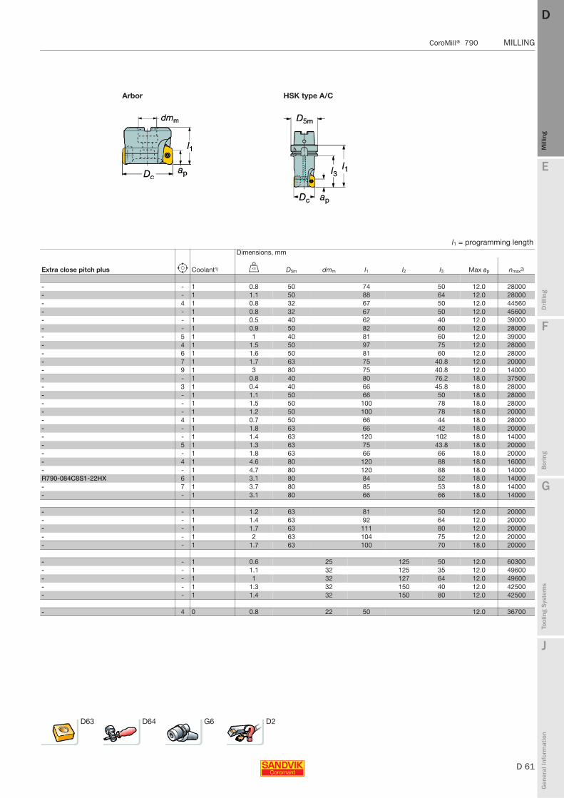
E
D 61
Mill
ing
Drilli
ng
F
Bor
ing
G
Tool
ing
Syst
ems
J
Gen
eral
Info
rmat
ion
DD
Mill
ing
CoroMill® 790 MILLING
MILLING CoroMill® 790
Arbor HSK type A/C
l1 = programming lengthDimensions, mm
Extra close pitch plus e Coolant1) U D5m dmm l1 l2 l3 Max ap nmax2)
- - 1 0.8 50 74 50 12.0 28000- - 1 1.1 50 88 64 12.0 28000- 4 1 0.8 32 67 50 12.0 44560- - 1 0.8 32 67 50 12.0 45600- - 1 0.5 40 62 40 12.0 39000- - 1 0.9 50 82 60 12.0 28000- 5 1 1 40 81 60 12.0 39000- 4 1 1.5 50 97 75 12.0 28000- 6 1 1.6 50 81 60 12.0 28000- 7 1 1.7 63 75 40.8 12.0 20000- 9 1 3 80 75 40.8 12.0 14000- - 1 0.8 40 80 76.2 18.0 37500- 3 1 0.4 40 66 45.8 18.0 28000- - 1 1.1 50 66 50 18.0 28000- - 1 1.5 50 100 78 18.0 28000- - 1 1.2 50 100 78 18.0 20000- 4 1 0.7 50 66 44 18.0 28000- - 1 1.8 63 66 42 18.0 20000- - 1 1.4 63 120 102 18.0 14000- 5 1 1.3 63 75 43.8 18.0 20000- - 1 1.8 63 66 66 18.0 20000- 4 1 4.6 80 120 88 18.0 16000- - 1 4.7 80 120 88 18.0 14000R790-084C8S1-22HX 6 1 3.1 80 84 52 18.0 14000- 7 1 3.7 80 85 53 18.0 14000- - 1 3.1 80 66 66 18.0 14000
- - 1 1.2 63 81 50 12.0 20000- - 1 1.4 63 92 64 12.0 20000- - 1 1.7 63 111 80 12.0 20000- - 1 2 63 104 75 12.0 20000- - 1 1.7 63 100 70 18.0 20000
- - 1 0.6 25 125 50 12.0 60300- - 1 1.1 32 125 35 12.0 49600- - 1 1 32 127 64 12.0 49600- - 1 1.3 32 150 40 12.0 42500- - 1 1.4 32 150 80 12.0 42500
- 4 0 0.8 22 50 12.0 36700
D63 D64 G6 D2
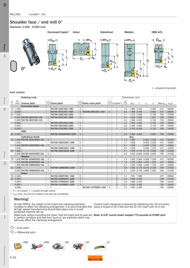
D 62
MILLING CoroMill® 790
E
Mill
ing
Drilli
ng
F
Bor
ing
G
Tool
ing
Syst
ems
J
Gen
eral
Info
rmat
ion
DDM
illin
g
MILLING CoroMill® 790
Shoulder face / end mill 0°Diameter 1.000 - 5.000 inch
Inch version
Coromant Capto® Arbor Cylindrical Weldon HSK A/C
l1 = programming length
Ordering code Dimensions, inch
KDc
inch Coarse pitch e Close pitch e Extra close pitch e Coolant1) V D5m l1 l2 l3 Max ap nmax2)
Coromant Capto 16 1.500 - - RA790-038C5S2-16M 3 - - 1 1.9 1.968 3.450 2.500 .472 39000
2.000 - - RA790-050C5S1-16M 3 RA790-050C5S1-16H 4 1 3.0 1.968 2.900 2.000 .472 2800022 1.500 - - RA790-038C4S2-22M 2 - - 1 1.7 1.575 3.000 2.130 .709 37500
2.000 RA790-050C5S1-22L 2 RA790-050C5S1-22M 3 - - 1 2.4 1.968 2.598 1.661 .709 200002.000 RA790-050C5S2-22L 2 - - - - 1 3.4 1.968 4.000 3.130 .709 280002.000 - - RA790-050C5S2-22M 3 - - 1 3.4 1.968 4.000 3.130 .709 200002.000 - - RA790-050C6S2-22M 3 - - 1 2.8 2.480 4.000 3.130 .709 200003.000 - - RA790-076C8S2-22M 3 - - 1 2.3 3.150 6.000 4.740 .709 14000
HSK22 2.000 - - RA790-050HA06S2-22M 3 - - 1 2.8 2.480 4.000 2.980 .709 20000
Cylindrical shank dmm
16 1.000 RA790-025O25S2-16L 2 - - - - 1 1.4 1.000 6.000 2.000 .472 603001.250 - - RA790-032O25S1-16M 3 - - 1 1.7 1.000 6.500 2.500 .472 499001.250 RA790-032O25S2-16L 2 - - - - 1 2.1 1.000 6.500 2.500 .472 499001.500 - - RA790-038O32S1-16M 3 - - 1 2.3 1.250 5.250 1.378 .472 43900
22 1.500 - - RA790-038O32S2-22M 2 - - 1 2.1 1.250 5.118 5.118 3.000 .709 375002.000 RA790-050O32S2-22L 2 - - - - 1 3.8 1.250 6.500 6.500 2.000 .709 31400
Weldon16 1.000 RA790-025M25S2-16L 2 - - - - 1 1.0 1.000 2.860 4.000 1.500 .472 60300
1.250 RA790-032M32S2-16L 2 - - - - 1 1.9 1.250 2.860 4.000 1.500 .472 499001.500 RA790-038M32S2-16L 2 - - - - 1 2.1 1.250 3.360 4.500 1.750 .472 43900
22 1.500 - - RA790-038M38S2-22M 2 - - 1 3.0 1.500 5.118 6.310 3.238 .709 375002.000 RA790-050M32S2-22L 2 - - - - 1 4.1 1.250 3.750 4.890 2.000 .709 31400
Arbor16 2.000 - - RA790-050R19S1-16M 3 - - 0 1.4 .750 1.580 .472 2800022 2.500 - - RA790-063R25S1-22M 3 - - 0 2.3 1.000 2.250 .709 24400
3.000 - - RA790-076R25S1-22M 3 - - 0 2.6 1.000 2.250 .709 244004.000 - - RA790-101R38S1-22M 4 - - 0 5.1 1.500 2.480 .709 200005.000 - - - - RA790-127R38S1-22H 5 0 7.5 1.500 2.480 .709 20000
1) 0 = no coolant, 1 = coolant through centre2) nmax (max. rev/min) for holders must also be considered.
Warning!At high RPM’s, the weight of the insert and clamping elements increase to affect the clamping arrangement. It is recommended that all high speed manufacturing should take place only in a well protected machine set up.
Correct insert clamping is received by tightening the 16 mm screw using a torque of 26 in-lbs and the 22 mm insert with 43 in-lbs.
Make sure, before mounting the insert, that the insert and its seat are in perfect condition and free from burrs or any particles which may seriously affect the clamping arrangement.
Note: A 0.67 ounce insert weighs 772 pounds at 37500 rpm!
e = Even pitch
i = Differential pitch
D63 D63 G6 D2 J3
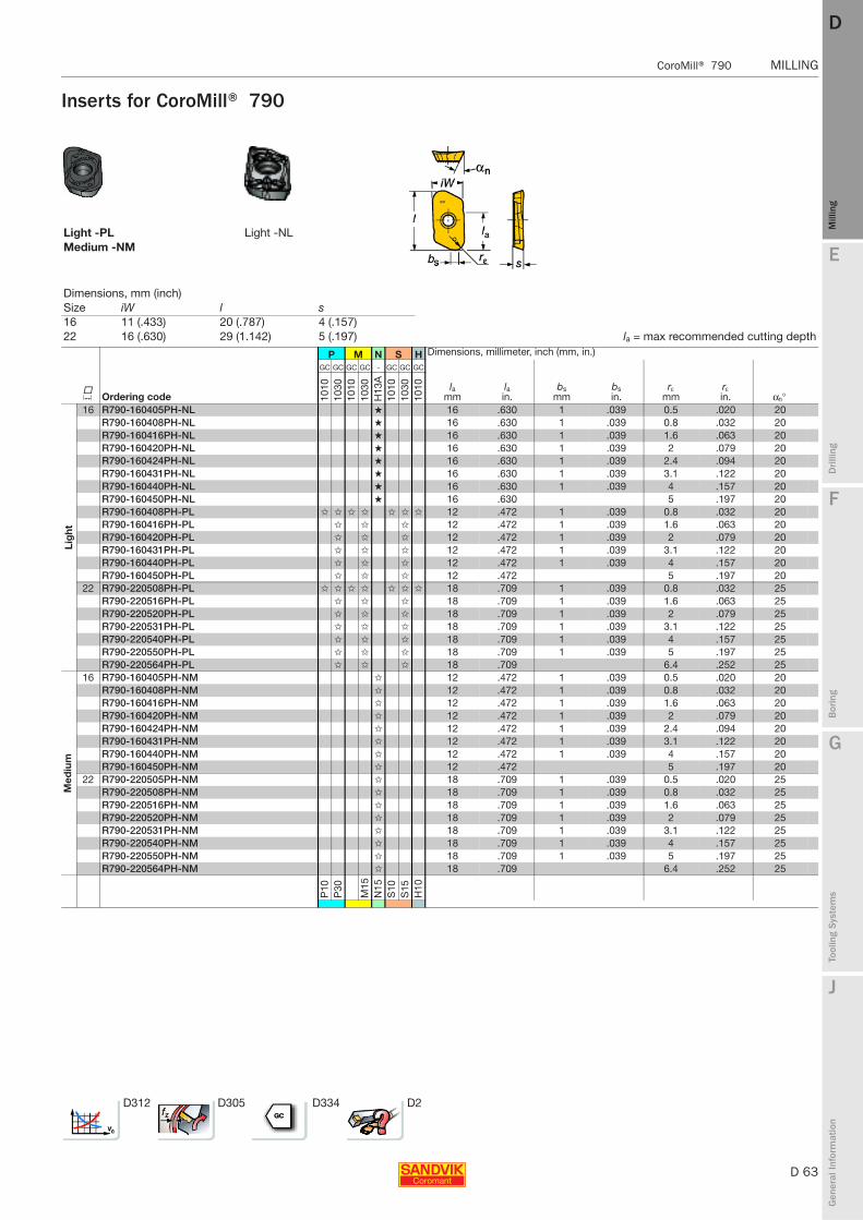
E
D 63
Mill
ing
Drilli
ng
F
Bor
ing
G
Tool
ing
Syst
ems
J
Gen
eral
Info
rmat
ion
DD
Mill
ing
CoroMill® 790 MILLING
MILLING CoroMill® 790
Inserts for CoroMill® 790
Light -PL Light -NLMedium -NM
Dimensions, mm (inch)Size iW l s 16 11 (.433) 20 (.787) 4 (.157)22 16 (.630) 29 (1.142) 5 (.197) la = max recommended cutting depth
P M N S H Dimensions, millimeter, inch (mm, in.)
K Ordering code
GC GC GC GC - GC GC GC
lamm
lain.
bsmm
bsin.
rεmm
rεin. αn°10
1010
3010
1010
30H
13A
1010
1030
1010
Lig
ht
16 R790-160405PH-NL ★ 16 .630 1 .039 0.5 .020 20R790-160408PH-NL ★ 16 .630 1 .039 0.8 .032 20R790-160416PH-NL ★ 16 .630 1 .039 1.6 .063 20R790-160420PH-NL ★ 16 .630 1 .039 2 .079 20R790-160424PH-NL ★ 16 .630 1 .039 2.4 .094 20R790-160431PH-NL ★ 16 .630 1 .039 3.1 .122 20R790-160440PH-NL ★ 16 .630 1 .039 4 .157 20R790-160450PH-NL ★ 16 .630 5 .197 20R790-160408PH-PL ✩ ✩ ✩ ✩ ✩ ✩ ✩ 12 .472 1 .039 0.8 .032 20R790-160416PH-PL ✩ ✩ ✩ 12 .472 1 .039 1.6 .063 20R790-160420PH-PL ✩ ✩ ✩ 12 .472 1 .039 2 .079 20R790-160431PH-PL ✩ ✩ ✩ 12 .472 1 .039 3.1 .122 20R790-160440PH-PL ✩ ✩ ✩ 12 .472 1 .039 4 .157 20R790-160450PH-PL ✩ ✩ ✩ 12 .472 5 .197 20
22 R790-220508PH-PL ✩ ✩ ✩ ✩ ✩ ✩ ✩ 18 .709 1 .039 0.8 .032 25R790-220516PH-PL ✩ ✩ ✩ 18 .709 1 .039 1.6 .063 25R790-220520PH-PL ✩ ✩ ✩ 18 .709 1 .039 2 .079 25R790-220531PH-PL ✩ ✩ ✩ 18 .709 1 .039 3.1 .122 25R790-220540PH-PL ✩ ✩ ✩ 18 .709 1 .039 4 .157 25R790-220550PH-PL ✩ ✩ ✩ 18 .709 1 .039 5 .197 25R790-220564PH-PL ✩ ✩ ✩ 18 .709 6.4 .252 25
Med
ium
16 R790-160405PH-NM ✩ 12 .472 1 .039 0.5 .020 20R790-160408PH-NM ✩ 12 .472 1 .039 0.8 .032 20R790-160416PH-NM ✩ 12 .472 1 .039 1.6 .063 20R790-160420PH-NM ✩ 12 .472 1 .039 2 .079 20R790-160424PH-NM ✩ 12 .472 1 .039 2.4 .094 20R790-160431PH-NM ✩ 12 .472 1 .039 3.1 .122 20R790-160440PH-NM ✩ 12 .472 1 .039 4 .157 20R790-160450PH-NM ✩ 12 .472 5 .197 20
22 R790-220505PH-NM ✩ 18 .709 1 .039 0.5 .020 25R790-220508PH-NM ✩ 18 .709 1 .039 0.8 .032 25R790-220516PH-NM ✩ 18 .709 1 .039 1.6 .063 25R790-220520PH-NM ✩ 18 .709 1 .039 2 .079 25R790-220531PH-NM ✩ 18 .709 1 .039 3.1 .122 25R790-220540PH-NM ✩ 18 .709 1 .039 4 .157 25R790-220550PH-NM ✩ 18 .709 1 .039 5 .197 25R790-220564PH-NM ✩ 18 .709 6.4 .252 25
P10
P30
M15
N15
S10
S15
H10
D312 D305 D334 D2
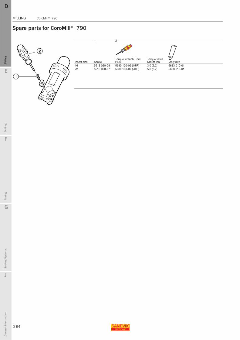
D 64
MILLING CoroMill® 790
E
Mill
ing
Drilli
ng
F
Bor
ing
G
Tool
ing
Syst
ems
J
Gen
eral
Info
rmat
ion
DDM
illin
g
MILLING CoroMill® 790
Spare parts for CoroMill® 790
1 2
Insert size ScrewTorque wrench (Torx Plus)
Torque value Nm (ft-lbs) Molykote
16 5513 020-09 5680 100-06 (15IP) 3.0 (2.2) 5683 010-0122 5513 020-07 5680 100-07 (20IP) 5.0 (3.7) 5683 010-01

E
D 65
Mill
ing
Drilli
ng
F
Bor
ing
G
Tool
ing
Syst
ems
J
Gen
eral
Info
rmat
ion
DD
Mill
ing
CoroMill® 690 MILLING
MILLING CoroMill® 690
CoroMill® 690
The cutting edge for titanium milling40-100 mm (1.500-4.000 inch)
Alignment of inserts ensures straightness within 0.1 mm (.004 inch)
Feed rate recommendations
SL geometry optimized for titanium
Locked-in precision with rigid stability higher productivity from product consistency
2 insert sizes
Oversized option
End insert
End insert
Side insert
Side insert
Marking
ISO application areas:
Pitch
mm inch
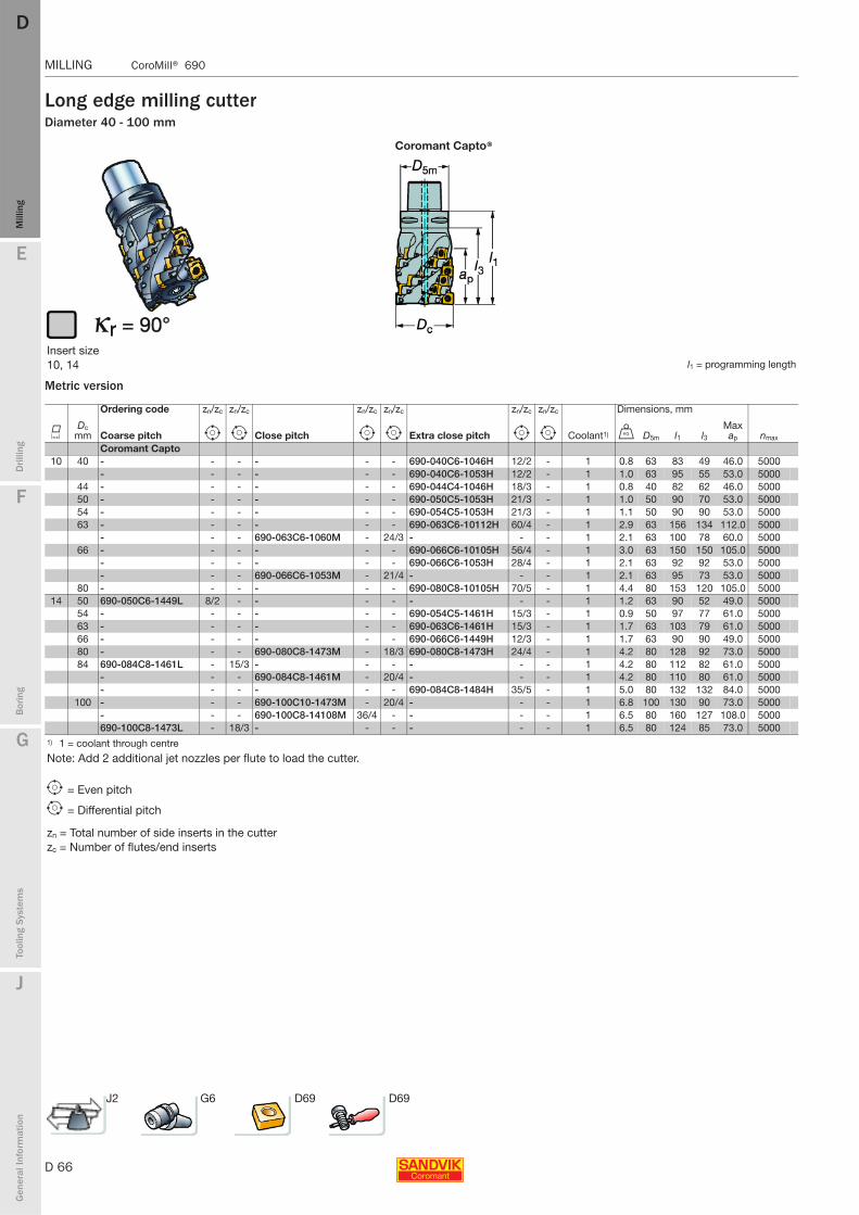
D 66
MILLING CoroMill® 690
E
Mill
ing
Drilli
ng
F
Bor
ing
G
Tool
ing
Syst
ems
J
Gen
eral
Info
rmat
ion
DDM
illin
g
MILLING CoroMill® 690
Long edge milling cutterDiameter 40 - 100 mm
Metric version
Coromant Capto®
Insert size 10, 14 l1 = programming length
Ordering code zn/zc zn/zc zn/zc zn/zc zn/zc zn/zc Dimensions, mm
KDc
mm Coarse pitch e i Close pitch e i Extra close pitch e i Coolant1) U D5m l1 l3Max ap nmax
Coromant Capto 10 40 - - - - - - 690-040C6-1046H 12/2 - 1 0.8 63 83 49 46.0 5000
- - - - - - 690-040C6-1053H 12/2 - 1 1.0 63 95 55 53.0 500044 - - - - - - 690-044C4-1046H 18/3 - 1 0.8 40 82 62 46.0 500050 - - - - - - 690-050C5-1053H 21/3 - 1 1.0 50 90 70 53.0 500054 - - - - - - 690-054C5-1053H 21/3 - 1 1.1 50 90 90 53.0 500063 - - - - - - 690-063C6-10112H 60/4 - 1 2.9 63 156 134 112.0 5000
- - - 690-063C6-1060M - 24/3 - - - 1 2.1 63 100 78 60.0 500066 - - - - - - 690-066C6-10105H 56/4 - 1 3.0 63 150 150 105.0 5000
- - - - - - 690-066C6-1053H 28/4 - 1 2.1 63 92 92 53.0 5000- - - 690-066C6-1053M - 21/4 - - - 1 2.1 63 95 73 53.0 5000
80 - - - - - - 690-080C8-10105H 70/5 - 1 4.4 80 153 120 105.0 500014 50 690-050C6-1449L 8/2 - - - - - - - 1 1.2 63 90 52 49.0 5000
54 - - - - - - 690-054C5-1461H 15/3 - 1 0.9 50 97 77 61.0 500063 - - - - - - 690-063C6-1461H 15/3 - 1 1.7 63 103 79 61.0 500066 - - - - - - 690-066C6-1449H 12/3 - 1 1.7 63 90 90 49.0 500080 - - - 690-080C8-1473M - 18/3 690-080C8-1473H 24/4 - 1 4.2 80 128 92 73.0 500084 690-084C8-1461L - 15/3 - - - - - - 1 4.2 80 112 82 61.0 5000
- - - 690-084C8-1461M - 20/4 - - - 1 4.2 80 110 80 61.0 5000- - - - - - 690-084C8-1484H 35/5 - 1 5.0 80 132 132 84.0 5000
100 - - - 690-100C10-1473M - 20/4 - - - 1 6.8 100 130 90 73.0 5000- - - 690-100C8-14108M 36/4 - - - - 1 6.5 80 160 127 108.0 5000690-100C8-1473L - 18/3 - - - - - - 1 6.5 80 124 85 73.0 5000
1) 1 = coolant through centre
Note: Add 2 additional jet nozzles per flute to load the cutter.
e = Even pitch
i = Differential pitch
zn = Total number of side inserts in the cutterzc = Number of flutes/end inserts
J2 G6 D69 D69
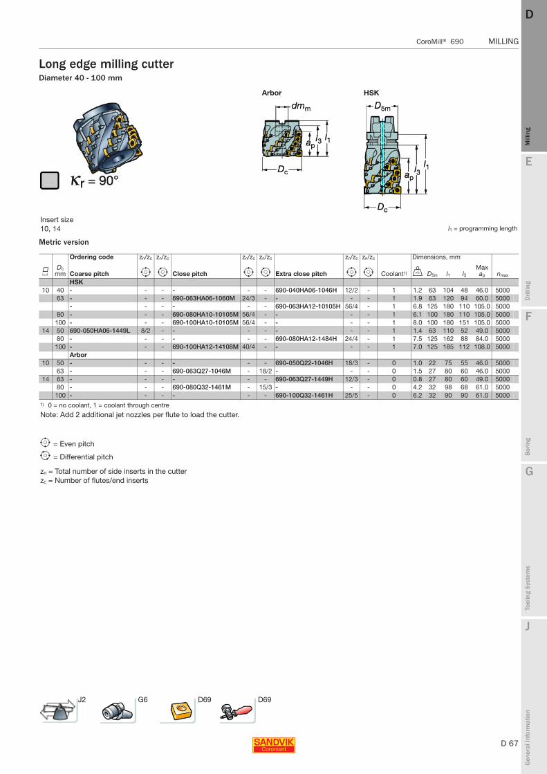
E
D 67
Mill
ing
Drilli
ng
F
Bor
ing
G
Tool
ing
Syst
ems
J
Gen
eral
Info
rmat
ion
DD
Mill
ing
CoroMill® 690 MILLING
MILLING CoroMill® 690
Long edge milling cutterDiameter 40 - 100 mm
Metric version
Arbor HSK
Insert size 10, 14 l1 = programming length
Ordering code zn/zc zn/zc zn/zc zn/zc zn/zc zn/zc Dimensions, mm
KDc
mm Coarse pitch e i Close pitch e i Extra close pitch e i Coolant1) U D5m l1 l3Max ap nmax
HSK10 40 - - - - - - 690-040HA06-1046H 12/2 - 1 1.2 63 104 48 46.0 5000
63 - - - 690-063HA06-1060M 24/3 - - - - 1 1.9 63 120 94 60.0 5000- - - - - - 690-063HA12-10105H 56/4 - 1 6.8 125 180 110 105.0 5000
80 - - - 690-080HA10-10105M 56/4 - - - - 1 6.1 100 180 110 105.0 5000100 - - - 690-100HA10-10105M 56/4 - - - - 1 8.0 100 180 151 105.0 5000
14 50 690-050HA06-1449L 8/2 - - - - - - - 1 1.4 63 110 52 49.0 500080 - - - - - - 690-080HA12-1484H 24/4 - 1 7.5 125 162 88 84.0 5000
100 - - - 690-100HA12-14108M 40/4 - - - - 1 7.0 125 185 112 108.0 5000Arbor
10 50 - - - - - - 690-050Q22-1046H 18/3 - 0 1.0 22 75 55 46.0 500063 - - - 690-063Q27-1046M - 18/2 - - - 0 1.5 27 80 60 46.0 5000
14 63 - - - - - - 690-063Q27-1449H 12/3 - 0 0.8 27 80 60 49.0 500080 - - - 690-080Q32-1461M - 15/3 - - - 0 4.2 32 98 68 61.0 5000
100 - - - - - - 690-100Q32-1461H 25/5 - 0 6.2 32 90 90 61.0 50001) 0 = no coolant, 1 = coolant through centre
Note: Add 2 additional jet nozzles per flute to load the cutter.
e = Even pitch
i = Differential pitch
zn = Total number of side inserts in the cutterzc = Number of flutes/end inserts
J2 G6 D69 D69

D 68
MILLING CoroMill® 690
E
Mill
ing
Drilli
ng
F
Bor
ing
G
Tool
ing
Syst
ems
J
Gen
eral
Info
rmat
ion
DDM
illin
g
MILLING CoroMill® 690
Long edge milling cutterDiameter 1.500 - 3.000 inch
Inch version
Inch version
Coromant Capto®
Insert size 10, 14 l1 = programming length
Ordering code zn/zc zn/zc zn/zc zn/zc zn/zc zn/zc Dimensions, inch
KDc
inch Coarse pitch e i Close pitch e i Extra close pitch e i Coolant1) V D5m l1 l3Max ap nmax
Coromant Capto 10 1.500 - - - - - - A690-038C6-1046H 12/2 - 1 1.8 2.480 3.268 1.890 1.811 5000
2.000 - - - - - - A690-051C5-1060H 24/3 - 1 2.4 1.968 3.937 3.937 2.362 5000- - - - - - A690-051C6-10105H 42/3 - 1 3.7 2.480 5.906 4.213 4.134 5000
2.500 - - - - - - A690-063C6-1060H 32/4 - 1 4.6 2.480 3.937 3.032 2.362 5000- - - A690-063C6-1060M - 24/3 - - - 1 4.6 2.480 4.016 3.150 2.362 5000
3.000 - - - A690-076C10-10105M 56/4 - - - - 1 15.4 3.937 6.496 4.252 4.134 5000- - - - - - A690-076C6-1075H 50/5 - 1 7.1 2.480 4.567 4.567 2.953 5000
14 2.000 - - - - - - A690-051C6-1449H 12/2 - 1 2.7 2.480 3.543 2.126 1.929 50002.500 - - - - - - A690-063C6-1461H 15/3 - 1 3.5 2.480 4.016 2.953 2.402 50003.000 - - - - - - A690-076C6-1473H 24/4 - 1 6.8 2.480 4.803 4.803 2.874 50004.000 A690-101C8-1473L - 15/3 - - - - - - 1 14.3 3.150 4.882 3.346 2.874 5000
1) 1 = coolant through centreNote: Add 2 additional jet nozzles per flute to load the cutter.
Arbor HSK
Insert size 10 , 14 l1 = programming length
Ordering code zn/zc zn/zc zn/zc zn/zc zn/zc zn/zc Dimensions, inch
KDc
inch Coarse pitch e i Close pitch e i Extra close pitch e i Coolant1) V D5m l1 l3Max ap nmax
HSK10 3.000 - - - A690-076HA10-10105M 56/4 - - - - 1 16.5 3.937 7.087 4.331 4.134 500014 3000 - - - A690-076HA12-1484M 18/3 - - - - 1 16.5 125 6.378 3.543 3.307 5000
4.000 A690-101HA10-1473L - 15/3 - - - - - - 1 14.3 3.937 5.433 4.291 3.780 50004.000 - - - A690-101HA12-1496M 28/4 - - - - 1 16.5 125 6.496 3.937 3.780 5000
Arbor10 2.000 - - - - - - A690-051R19-1046H 18/3 - 0 2.2 .750 2.992 2.205 1.811 5000
3.000 - - - - - - A690-076R31-10105H 70/5 - 0 10.1 1.250 5.906 4.980 4.134 50001) 0 = no coolant, 1 = coolant through centreNote: Add 2 additional jet nozzles per flute to load the cutter.
e = Even pitch
i = Differential pitch
zn = Total number of side inserts in the cutter
zc = Number of flutes/end inserts
J2 G6 D69 D69

E
D 69
Mill
ing
Drilli
ng
F
Bor
ing
G
Tool
ing
Syst
ems
J
Gen
eral
Info
rmat
ion
DD
Mill
ing
CoroMill® 690 MILLING
MILLING CoroMill® 690
Inserts for CoroMill® 690 long edge cutter
Spare parts
P-SL E-SLSide insert End insert
Dimensions, mm (inch)Size iC iW la s 10 10 (.394) 10.01(.394) 10 (.394) 5.2 (.205)14 14.5 (.571) 14.5 (.571) 14.75 (.581) 6.35 (.250)
S Dimensions, millimeter, inch (mm, in.)
Insert size Ordering code
GC GC GC GC
bsmm
bsin.
rεmm
rεin.10
3020
40S
30T
S40
T
Lig
ht
10 690-100510M-P-SL ★ ✩ ★ ★ 1.0 .03914 690-140610M-P-SL ★ ✩ ★ ★ 1.0 .03910 690-100508M-E-SL ★ ✩ ★ ★ 1.0 .039 0.8 .032
690-100512M-E-SL ✩ ✩ ★ ★ 1.0 .039 1.2 .047690-100516M-E-SL ★ ✩ ★ ★ 1.0 .039 1.6 .063690-100520M-E-SL ✩ ✩ ★ ★ 1.0 .039 2.0 .079690-100524M-E-SL ✩ ✩ ★ ★ 1.0 .039 2.4 .094690-100531M-E-SL ✩ ✩ ★ ★ 1.0 .039 3.1 .122
14 690-140608M-E-SL ★ ✩ ★ ★ 1.0 .039 0.8 .032690-140612M-E-SL ✩ ✩ ★ ★ 1.0 .039 1.2 .047690-140616M-E-SL ★ ✩ ★ ★ 1.0 .039 1.6 .063690-140620M-E-SL ✩ ✩ ★ ★ 1.0 .039 2.0 .079690-140624M-E-SL ✩ ✩ ★ ★ 1.0 .039 2.4 .094690-140631M-E-SL ✩ ✩ ★ ★ 1.0 .039 3.1 .122690-140640M-E-SL ✩ ✩ ★ ★ 1.0 .039 4.0 .157690-140650M-E-SL ✩ ✩ ★ ★ 1.0 .039 5.0 .197690-140660M-E-SL ✩ ✩ ★ ★ 1.0 .039 6.0 .236690-140664M-E-SL ✩ ✩ ★ ★ 1.0 .039 6.35 .250
S15
S30
S25
S35
★= First choice
1 2
J Insert screw Key (Torx Plus)Torque value
Torque wrench2)Nm In-lbs10 5513 020-68 5680 046-02 (15IP) 3.0 26 5680 100 06 (15IP)14 5513 020-55 5680 046-06 (20IP) 5.0 44 5680 100-07 (20IP)
Coolant holes32) / 51) 4 / 6 7
Cutter dia Plug screwNozzle2)
Key (mm)2)(dia 1.0 mm)40-44 mm (1.500 inch) 3214 010-202 5691 026-13 174.1-862(1.5)50-100 mm (2.000-4.000 inch) 3214 010-253 5691 026-03 170.3-864(2.0)3)
Optional nozzles (to be ordered separately)
Cutter dia 40-44 mm (1.500 inch) Cutter dia 50- mm (2.000- inch)Ordering code Hole diameter, mm Ordering code Hole diameter, mm5691 026-11 0.6 5691 026-01 0.65691 026-12 0.8 5691 026-02 0.85691 026-13 1.0 5691 026-03 1.05691 026-14 1.2 5691 026-04 1.25691 026-15 1.4 5691 026-05 1.41) Delivered with the tool2) Optional part delivered to separate order.3) No torque required
D312 D305

D 70
MILLING Coromant Finishing Long Edge Cutter
E
Mill
ing
Drilli
ng
F
Bor
ing
G
Tool
ing
Syst
ems
J
Gen
eral
Info
rmat
ion
DDM
illin
g
MILLING Coromant Finishing Long Edge Cutter
Coromant Finishing Long Edge Cutter
Superior surface finish from an indexable long edge
Coromant Finishing Long Edge Cutter
Metric version
Inch version
- Choose from many mounting options. Cutting depth ap 4.00 - 6.00 inch (100 - 150 mm) depending on diameter
- Precision tolerance cutter body and unique insert cutting edge produce solid/brazed tool surface finish
- NO MISMATCH BETWEEN INSERTS- Unbeatable surface- Reduced inventory costs- Hassle free machining- Low power consumption
Dc 2.000-5.000 inch (19 mm side/18 mm end insert)
Coromant Capto®
Ordering code zn/zc Dimensions, mm
Dc mm Coarse pitch e i D5m l1 l3 Max ap
Coromant Capto 50 R215-050C5-100L 16/2 - 50 141.5 121.5 10080 R215-080C8-150L 24/2 - 80 200 150
Ordering code zn/zc Dimensions, inch
Dc inch Coarse pitch e i D5m l1 l3 Max ap
Coromant Capto 2.000 RA215-051C5-102L 16/2 - 1.968 5.821 4.0003.000 RA215-076C8-152L 25/2 - 3.150 7.874 6.690 6.000
e = Even pitch
i = Differential pitch
zn= Number of insert in the cutter Zn = 16zc= Effective number of rows Zc = 2
D71 D71 G6 D2
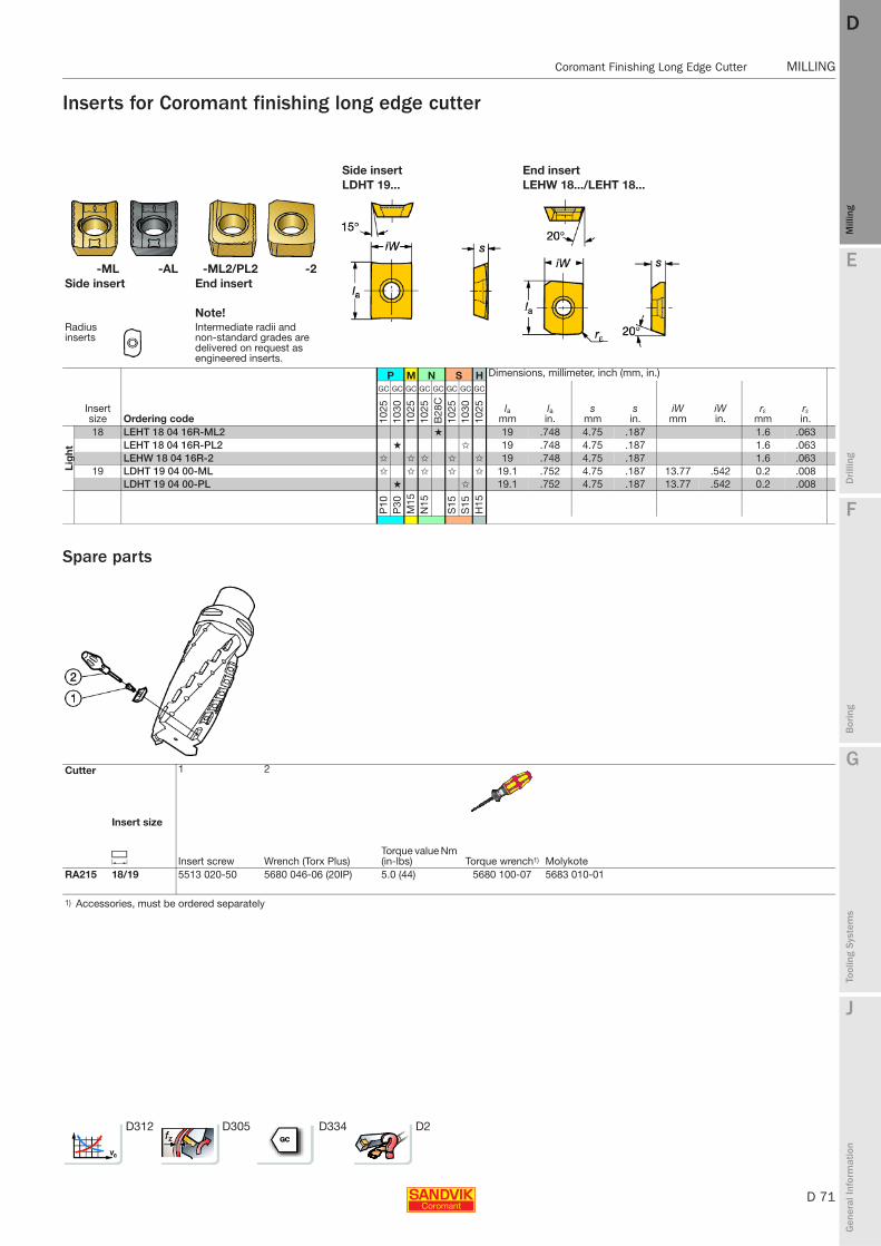
E
D 71
Mill
ing
Drilli
ng
F
Bor
ing
G
Tool
ing
Syst
ems
J
Gen
eral
Info
rmat
ion
DD
Mill
ing
Coromant Finishing Long Edge Cutter MILLING
MILLING Coromant Finishing Long Edge Cutter
Inserts for Coromant finishing long edge cutter
Spare parts
Side insert End insertLDHT 19... LEHW 18.../LEHT 18...
-ML -AL -ML2/PL2 -2Side insert End insert
Note!Radius inserts
Intermediate radii and non-standard grades are delivered on request as engineered inserts.
P M N S H Dimensions, millimeter, inch (mm, in.)
Insert size Ordering code
GC GC GC GC GC GC GC GC
lamm
lain.
smm
sin.
iWmm
iWin.
rεmm
rεin.10
2510
3010
2510
25B
28C
1025
1030
1025
Lig
ht
18 LEHT 18 04 16R-ML2 ★ 19 .748 4.75 .187 1.6 .063LEHT 18 04 16R-PL2 ★ ✩ 19 .748 4.75 .187 1.6 .063LEHW 18 04 16R-2 ✩ ✩ ✩ ✩ ✩ 19 .748 4.75 .187 1.6 .063
19 LDHT 19 04 00-ML ✩ ✩ ✩ ✩ ✩ 19.1 .752 4.75 .187 13.77 .542 0.2 .008LDHT 19 04 00-PL ★ ✩ 19.1 .752 4.75 .187 13.77 .542 0.2 .008
P10
P30
M15
N15
S15
S15
H15
Cutter
Insert size
1 2
C Insert screw Wrench (Torx Plus)Torque value Nm (in-lbs) Torque wrench1) Molykote
RA215 18/19 5513 020-50 5680 046-06 (20IP) 5.0 (44) 5680 100-07 5683 010-01
1) Accessories, must be ordered separately
D312 D305 D334 D2

D 72
MILLING CoroMill® 210
E
Mill
ing
Drilli
ng
F
Bor
ing
G
Tool
ing
Syst
ems
J
Gen
eral
Info
rmat
ion
DDM
illin
g
MILLING CoroMill® 210
CoroMill® 210 Versatile cutter for both high feed face milling and plunge milling
Highly productive roughing cutter
Diameter 25 - 160 mm (1.000 - 6.000 inch)
Plunge millingHigh feed helical interpolation
High feed face milling
10° entering angle results in favourable cutting forces directed towards the spindle.
ISO application areas: Tool options designed to individual customer requirements are available. For information on our Tailor Made programme see page J3.
Dimensions, mm (inch)l ap ae
09 1.2 (.047) 8 (.315)14 2.0 (.079) 13 (.512)
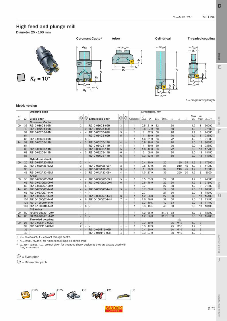
E
D 73
Mill
ing
Drilli
ng
F
Bor
ing
G
Tool
ing
Syst
ems
J
Gen
eral
Info
rmat
ion
DD
Mill
ing
CoroMill® 210 MILLING
MILLING CoroMill® 210
High feed and plunge millDiameter 25 - 160 mm
Metric version
Coromant Capto® Arbor Cylindrical Threaded coupling
l1 = programming length
Ordering code Dimensions, mm
K D3 Close pitch e i Extra close pitch e i Coolant1) U Dc D5m dmm l1 l2 l3Max ap
ae max nmax2)
Coromant Capto 09 36 R210-036C3-09M 2 - R210-036C3-09H 3 - 1 0.5 21.9 32 50 1.2 8 30900
42 R210-042C4-09M - 3 R210-042C4-09H 4 - 1 0.8 27.9 40 60 1.2 8 2760052 R210-052C5-09M - 4 R210-052C5-09H 5 - 1 1 37.9 50 70 1.2 8 2400054 - - - R210-054C5-09H 5 - 1 1 39.9 50 70 1.2 8 2360066 R210-066C6-09M - 6 - - - 1 1.6 51.9 63 72 1.2 8 21300
14 52 R210-052C5-14M - 3 R210-052C5-14H 4 - 1 0.9 28.0 50 70 2.0 13 2080054 - - - R210-054C5-14H 4 - 1 1 30.0 50 70 2.0 13 2360066 R210-066C6-14M - 4 R210-066C6-14H 5 - 1 1.6 42.0 63 72 2.0 13 1770082 R210-082C8-14M - 5 R210-082C8-14H 6 - 1 3 58.0 80 80 2.0 13 1510086 - - - R210-086C8-14H 6 - 1 3.2 62.0 80 80 2.0 13 14700
Cylindrical shank09 25 R210-025A20-09M 2 - - - - 1 0.4 10.9 20 180 35 1.2 8 17200
32 R210-032A25-09M 2 - R210-032A25-09H 3 - 1 0.8 17.9 25 210 45 1.2 8 1100035 - - - R210-035A32-09H 3 - 1 1 20.9 32 210 45 1.2 8 1100042 R210-042A32-09M - 3 R210-042A32-09H 4 - 1 1.5 27.9 32 250 50 1.2 8 8000
Arbor09 50 R210-050Q22-09M - 4 R210-050Q22-09H 5 - 1 0.5 35.9 22 50 1.2 8 24500
63 R210-063Q22-09M - 5 R210-063Q22-09H 6 - 1 0.6 48.9 22 50 1.2 8 2180063 R210-063Q27-09M - 5 - - - 1 0.7 27 50 1.2 8 21800
14 63 R210-063Q22-14M - 4 R210-063Q22-14H 5 - 1 0.7 39.0 22 50 2.0 13 1830063 R210-063Q27-14M - 4 - - - 1 0.7 27 50 2.0 13 1830080 R210-080Q27-14M - 5 R210-080Q27-14H 6 - 1 1.2 56.0 27 50 2.0 13 15400
100 R210-100Q32-14M - 6 R210-100Q32-14H 7 - 1 1.6 76.0 32 50 2.0 13 13400125 R210-125Q40-14M - 7 - - - 1 3.3 101. 40 63 2.0 13 11400160 R210-160Q40-14M - 8 - - - 1 5.3 136. 40 63 2.0 13 10400
CIS Arbor09 80 RA210-080J31-09M - 7 - - - 1 1.2 65.9 31.75 63 1.2 8 1880014 80 RA210-080J31-14M - 5 - - - 1 1.2 56.0 31.75 63 2.0 13 15400
Threaded coupling dth
09 25 R210-025T12-09M3) 2 - - - - 1 0.2 10.9 35 M12 1.2 832 R210-032T16-09M3) 2 - - - - 1 0.3 17.9 45 M16 1.2 835 - - - R210-035T16-09H 3 - 1 0.4 20.9 50 M16 1.2 842 - - - R210-042T16-09H 4 - 1 0.3 27.9 50 M16 1.2 8
1) 0 = no coolant, 1 = coolant through centre2) nmax (max. rev/min) for holders must also be considered.3) Max. rpm values, nmax, are not given for threaded shank design as they are always used with
long extensions.
e = Even pitch
i = Differential pitch
D75 D75 G6 D2 J3
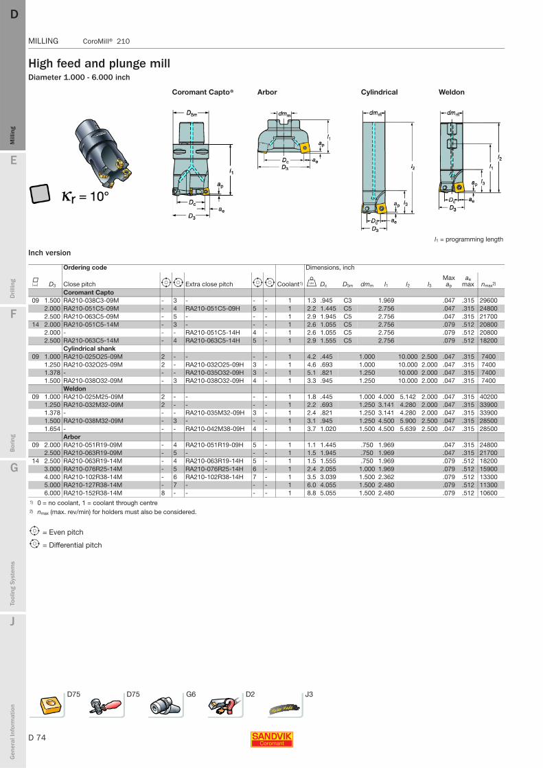
D 74
MILLING CoroMill® 210
E
Mill
ing
Drilli
ng
F
Bor
ing
G
Tool
ing
Syst
ems
J
Gen
eral
Info
rmat
ion
DDM
illin
g
MILLING CoroMill® 210
High feed and plunge millDiameter 1.000 - 6.000 inch
Inch version
Coromant Capto® Arbor Cylindrical Weldon
l1 = programming length
Ordering code Dimensions, inch
K D3 Close pitch e i Extra close pitch e i Coolant1) V Dc D5m dmm l1 l2 l3Max ap
ae max nmax2)
Coromant Capto 09 1.500 RA210-038C3-09M - 3 - - - 1 1.3 .945 C3 1.969 .047 .315 29600
2.000 RA210-051C5-09M - 4 RA210-051C5-09H 5 - 1 2.2 1.445 C5 2.756 .047 .315 248002.500 RA210-063C5-09M - 5 - - - 1 2.9 1.945 C5 2.756 .047 .315 21700
14 2.000 RA210-051C5-14M - 3 - - - 1 2.6 1.055 C5 2.756 .079 .512 208002.000 - - - RA210-051C5-14H 4 - 1 2.6 1.055 C5 2.756 .079 .512 208002.500 RA210-063C5-14M - 4 RA210-063C5-14H 5 - 1 2.9 1.555 C5 2.756 .079 .512 18200
Cylindrical shank09 1.000 RA210-025O25-09M 2 - - - - 1 4.2 .445 1.000 10.000 2.500 .047 .315 7400
1.250 RA210-032O25-09M 2 - RA210-032O25-09H 3 - 1 4.6 .693 1.000 10.000 2.000 .047 .315 74001.378 - - - RA210-035O32-09H 3 - 1 5.1 .821 1.250 10.000 2.000 .047 .315 74001.500 RA210-038O32-09M - 3 RA210-038O32-09H 4 - 1 3.3 .945 1.250 10.000 2.000 .047 .315 7400
Weldon09 1.000 RA210-025M25-09M 2 - - - - 1 1.8 .445 1.000 4.000 5.142 2.000 .047 .315 40200
1.250 RA210-032M32-09M 2 - - - - 1 2.2 .693 1.250 3.141 4.280 2.000 .047 .315 339001.378 - - - RA210-035M32-09H 3 - 1 2.4 .821 1.250 3.141 4.280 2.000 .047 .315 339001.500 RA210-038M32-09M - 3 - - - 1 3.1 .945 1.250 4.500 5.900 2.500 .047 .315 285001.654 - - - RA210-042M38-09H 4 - 1 3.7 1.020 1.500 4.500 5.639 2.500 .047 .315 28500
Arbor09 2.000 RA210-051R19-09M - 4 RA210-051R19-09H 5 - 1 1.1 1.445 .750 1.969 .047 .315 24800
2.500 RA210-063R19-09M - 5 - - - 1 1.5 1.945 .750 1.969 .047 .315 2170014 2.500 RA210-063R19-14M - 4 RA210-063R19-14H 5 - 1 1.5 1.555 .750 1.969 .079 .512 18200
3.000 RA210-076R25-14M - 5 RA210-076R25-14H 6 - 1 2.4 2.055 1.000 1.969 .079 .512 159004.000 RA210-102R38-14M - 6 RA210-102R38-14H 7 - 1 3.5 3.039 1.500 2.362 .079 .512 133005.000 RA210-127R38-14M - 7 - - - 1 6.0 4.055 1.500 2.480 .079 .512 113006.000 RA210-152R38-14M 8 - - - - 1 8.8 5.055 1.500 2.480 .079 .512 10600
1) 0 = no coolant, 1 = coolant through centre2) nmax (max. rev/min) for holders must also be considered.
e = Even pitch
i = Differential pitch
D75 D75 G6 D2 J3

E
D 75
Mill
ing
Drilli
ng
F
Bor
ing
G
Tool
ing
Syst
ems
J
Gen
eral
Info
rmat
ion
DD
Mill
ing
CoroMill® 210 MILLING
MILLING CoroMill® 210
Inserts for CoroMill® 210
12M 14E M-XM E-XM
Dimensions, mm (inch)Size E-xM M-xM
l = iC s l = iC s 09 9.5 (.374) 4.50 (.177) 9.4 (.370) 4.00 (.158)14 14.6 (.575) 5.26 (.207) 14.5 (.571) 4.76 (.188)
P M K S H Dimensions, millimeter, inch (mm, in.)
J Ordering code
GC GC GC GC GC GC GC GC GC GC GC GC GC GC GC GC GC GC GC GC GC GC GC GC
bsmm
bsin.
rεmm
rεin.10
3020
3020
4030
4042
2042
3042
4010
3010
4020
3020
4010
2030
4042
2010
1010
3020
3020
40S
30T
S40
T10
1010
3030
4042
20
Med
ium
09 R210-09 04 12M-MM ✩ ✩ ✩ ✩ ★ ★ ✩ 1.0 .039 1.2 .047R210-09 04 12M-PM ✩ ✩ ★ ✩ ✩ ✩ ✩ ✩ ★ ★ ★ ✩ ✩ 1.0 .039 1.2 .047R210-09 04 14E-KM ✩ ★ ✩ ✩ 0.8 .032 1.4 .055R210-09 04 14E-MM ✩ ✩ ✩ ✩ ★ ★ ✩ 0.8 .032 1.4 .055R210-09 04 14E-PM ★ ✩ ✩ ✩ ✩ ✩ ✩ ✩ ★ ★ ★ ✩ ✩ 0.8 .032 1.4 .055
Med
ium
14 R210-14 05 12M-KM ✩ ✩ ✩ ✩ 1.0 .039 1.2 .047R210-14 05 12M-MM ✩ ✩ ✩ ✩ ★ ★ ✩ 1.0 .039 1.2 .047R210-14 05 12M-PM ✩ ✩ ★ ✩ ✩ ✩ ✩ ✩ ★ ★ ★ ✩ ✩ 1.0 .039 1.2 .047R210-14 05 14E-KM ✩ ★ ✩ ✩ 0.9 .035 1.4 .055R210-14 05 14E-MM ✩ ✩ ✩ ✩ ★ ★ ✩ 0.9 .035 1.4 .055R210-14 05 14E-PM ★ ✩ ✩ ✩ ✩ ✩ ✩ ✩ ★ ★ ★ ✩ ✩ 0.9 .035 1.4 .055
P30
P25
P40
P20
P15
P25
P40
M15
M35
M25
M30
K20
K30
K25
S10
S15
S25
S30
S25
S35
H10
H10
H25
H25
D312 D305 D334 D2
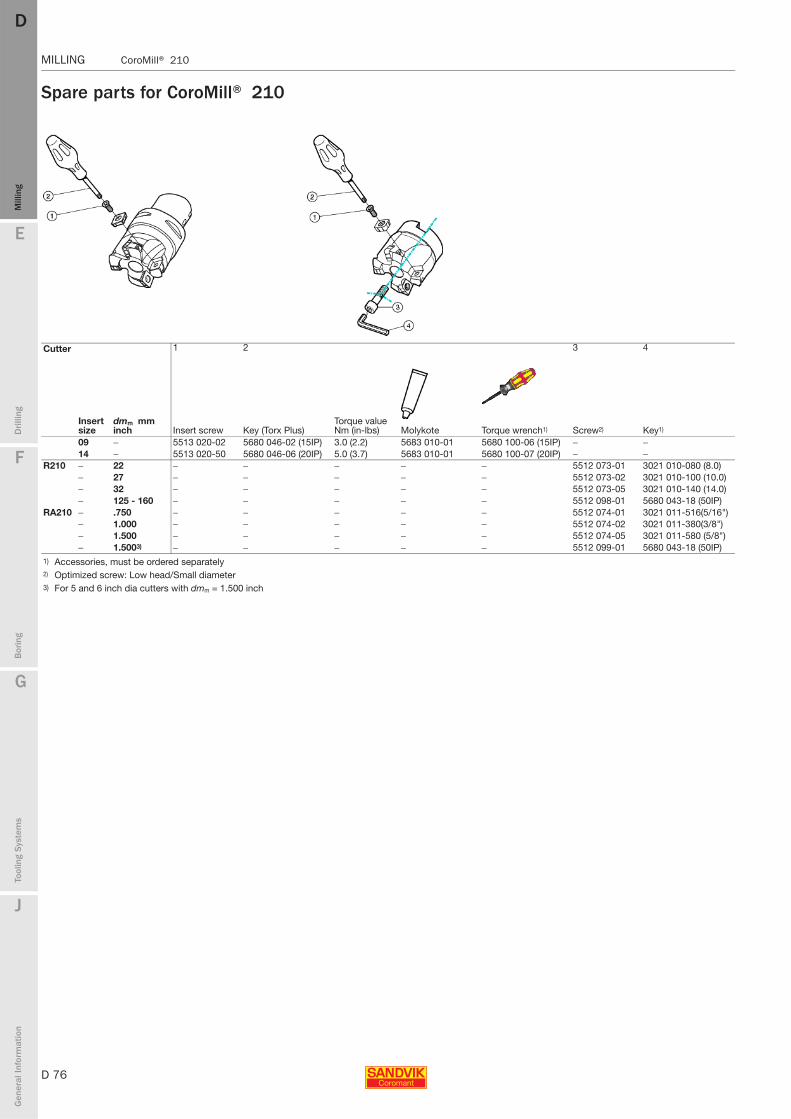
D 76
MILLING CoroMill® 210
E
Mill
ing
Drilli
ng
F
Bor
ing
G
Tool
ing
Syst
ems
J
Gen
eral
Info
rmat
ion
DDM
illin
g
MILLING CoroMill® 210
Spare parts for CoroMill® 210
Cutter 1 2 3 4
Insert size
dmm mm inch Insert screw Key (Torx Plus)
Torque value Nm (in-lbs) Molykote Torque wrench1) Screw2) Key1)
09 − 5513 020-02 5680 046-02 (15IP) 3.0 (2.2) 5683 010-01 5680 100-06 (15IP) − −14 − 5513 020-50 5680 046-06 (20IP) 5.0 (3.7) 5683 010-01 5680 100-07 (20IP) − −
R210 − 22 − − − − − 5512 073-01 3021 010-080 (8.0)− 27 − − − − − 5512 073-02 3021 010-100 (10.0)− 32 − − − − − 5512 073-05 3021 010-140 (14.0)− 125 - 160 − − − − − 5512 098-01 5680 043-18 (50IP)
RA210 − .750 − − − − − 5512 074-01 3021 011-516(5/16")− 1.000 − − − − − 5512 074-02 3021 011-380(3/8")− 1.500 − − − − − 5512 074-05 3021 011-580 (5/8")− 1.5003) − − − − − 5512 099-01 5680 043-18 (50IP)
1) Accessories, must be ordered separately 2) Optimized screw: Low head/Small diameter3) For 5 and 6 inch dia cutters with dmm = 1.500 inch

E
D 77
Mill
ing
Drilli
ng
F
Bor
ing
G
Tool
ing
Syst
ems
J
Gen
eral
Info
rmat
ion
DD
Mill
ing
CoroMill® 210 MILLING
MILLING CoroMill® 210
Feed recommendations for CoroMill® 210Cutting data
High feed machining
Programming
Plunging
Feed values fz mm/tooth fz inch/tooth fz mm/tooth fz inch/tooth
Insert size Tool overhang <= 3 x D3 <= 3 x D3 > 3 x D3 > 3 x D3
iC Starting value (min.- max.) Starting value (min.- max.) Starting value (min.- max.) Starting value (min.- max.)
9 0.15 (0.01-0.2) .006 (.004-.008) 0.10 (0.08-0.15) .004 (.003-.006)14 0.20 (0.10-0.25) .008 (.004-.010) 0.15 (0.10-0.20) .006 (.004-.008)
Speed and feed values, feed per toothInsert size 9 Insert size 14
Material fz mm/tooth fz inch/tooth fz mm/tooth fz inch/toothCMC No HB fz rec fz min - fz max fz rec fz min - fz max fz rec fz min - fz max fz rec fz min - fz max
P Unalloyed steel01.1/01.2 125-150 1.5 (0.4-2.0) .060 (.016-.080) 2.0 (0.4-3.0) .080 (.016-.118)Low alloy steel02.1 175 1.5 (0.4-2.0) .060 (.016-.080) 2.0 (0.4-3.0) .080 (.016-.118)02.2 330 1.0 (0.4-1.5) .040 (.016-.080) 1.5 (0.4-2.0) .060 (.016-.080)High alloy steel03.11 200 1.5 (0.4-1.7) .060 (.016-.067) 2.0 (0.4-2.5) .080 (.016-.098)03.21 300 1.0 (0.4-1.5) .040 (.016-.059) 1.5 (0.4-2.0) .060 (.016-.080)
M Stainless steel 05.11 200 1.5 (0.4-1.7) .060 (.016-.067) 2.0 (0.4-2.5) .080 (.016-.098)05.21 200 1.2 (0.4-1.5) .040 (.016-.060) 1.5 (0.4-2.0) .060 (.016-.080)
K Grey cast iron08.2 245 1.5 (0.4-2.0) .060 (.016-.080) 2.0 (0.4-3.0) .080 (.016-.118)Nodular cast iron 09.2 250 1.5 (0.4-2.0) .060 (.016-.080) 2.0 (0.4-3.0) .080 (.016-.118)
S Heat resistant alloys20.22 350 0.8 (0.5-1.2) .030 (.020-.047) 1.0 (0.5-1.5) .040 (.020-.060)Titanium alloys23.22 10501) 0.8 (0.5-1.2) .030 (.020-.047) 1.0 (0.5-1.5) .040 (.020-.060)
H Hardened steel04.1 45-55 0.8 (0.4-1.2) .030 (.016-.047) 1.0 (0.4-1.5) .040 (.016-.118)
1) Rm = ultimate tensile strength measured in MPa.
iC Dimensions, mm (inch)Uncut material
R b ap x9 2.5 7.05 1.2 0.79
(.098) (.278) (.047) (.031)14 3.5 12.0 2.0 1.48
(.138) (.472) (.079) (.058)
Caution needs to be taken when high feed milling against a steep wall. Reduce feed by 50%.
When recommended machining strategy for machining corners is not followed, feed rate has to be reduced by 50% when machining corners.
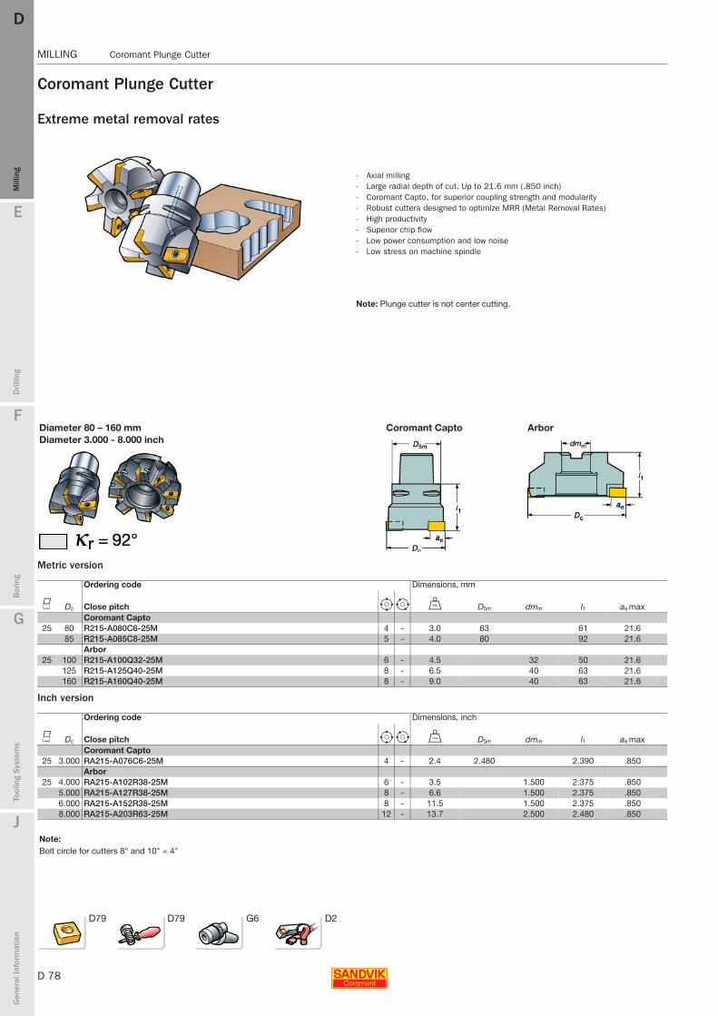
D 78
MILLING Coromant Plunge Cutter
E
Mill
ing
Drilli
ng
F
Bor
ing
G
Tool
ing
Syst
ems
J
Gen
eral
Info
rmat
ion
DDM
illin
g
MILLING Coromant Plunge Cutter
Coromant Plunge Cutter
Extreme metal removal rates
Metric version
Inch version
- Axial milling- Large radial depth of cut. Up to 21.6 mm (.850 inch) - Coromant Capto, for superior coupling strength and modularity- Robust cutters designed to optimize MRR (Metal Removal Rates)- High productivity- Superior chip flow- Low power consumption and low noise- Low stress on machine spindle
Note: Plunge cutter is not center cutting.
Diameter 80 – 160 mm Coromant Capto ArborDiameter 3.000 - 8.000 inch
Ordering code Dimensions, mm
K Dc Close pitch e i U D5m dmm l1 ae maxCoromant Capto
25 80 R215-A080C6-25M 4 - 3.0 63 61 21.685 R215-A085C8-25M 5 - 4.0 80 92 21.6
Arbor25 100 R215-A100Q32-25M 6 - 4.5 32 50 21.6
125 R215-A125Q40-25M 8 - 6.5 40 63 21.6160 R215-A160Q40-25M 8 - 9.0 40 63 21.6
Ordering code Dimensions, inch
K Dc Close pitch e i V D5m dmm l1 ae maxCoromant Capto
25 3.000 RA215-A076C6-25M 4 - 2.4 2.480 2.390 .850Arbor
25 4.000 RA215-A102R38-25M 6 - 3.5 1.500 2.375 .8505.000 RA215-A127R38-25M 8 - 6.6 1.500 2.375 .8506.000 RA215-A152R38-25M 8 - 11.5 1.500 2.375 .8508.000 RA215-A203R63-25M 12 - 13.7 2.500 2.480 .850
Note:Bolt circle for cutters 8" and 10" = 4"
D79 D79 G6 D2
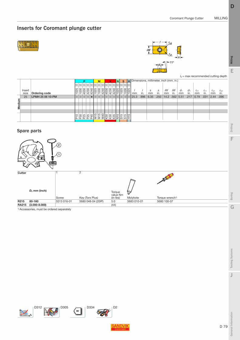
E
D 79
Mill
ing
Drilli
ng
F
Bor
ing
G
Tool
ing
Syst
ems
J
Gen
eral
Info
rmat
ion
DD
Mill
ing
Coromant Plunge Cutter MILLING
MILLING Coromant Plunge Cutter
Inserts for Coromant plunge cutter
Spare parts
la = max recommended cutting depth
P M K N S H Dimensions, millimeter, inch (mm, in.)
Insert size Ordering code
GC GC GC GC GC GC GC GC GC GC GC GC GC GC GC
lmm
lin.
smm
sin.
iWmm
iWin.
d1mm
d1in.
rε1mm
rε1in.
rε2mm
rε2in.10
2510
3040
3042
3042
4010
2510
3042
4040
3042
3042
4010
2510
2510
3010
25
Med
ium
25 LPMH 25 06 10-PM ✩ ✩ ✩ ✩ ★ ✩ ✩ ✩ ✩ ✩ ✩ ✩ ✩ ✩ ✩ 25.3 .996 6.35 .250 14.2 .562 5.51 .217 0.79 .031 2.44 .096
P10
P30
P25
P25
P40
M15
M15
M40
K30
K30
K35
N15
S15
S15
H15
Cutter 1 2
Dc mm (inch)
Screw Key (Torx Plus)
Torque value Nm (in-lbs) Molykote Torque wrench1)
R215 80-160 5513 016-01 5680 048-04 (20IP) 5.0 5683 010-01 5680 100-07RA215 (3.000-8.000) (44)1) Accessories, must be ordered separately
D312 D305 D334 D2

Rotating_Utfyllnadssidor.indd 2 2010-12-09 12:30:02
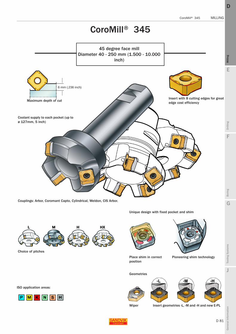
E
D 81
Mill
ing
Drilli
ng
F
Bor
ing
G
Tool
ing
Syst
ems
J
Gen
eral
Info
rmat
ion
DD
Mill
ing
CoroMill® 345 MILLING
MILLING CoroMill® 345
CoroMill® 345
45 degree face millDiameter 40 - 250 mm (1.500 - 10.000
inch)
Insert with 8 cutting edges for greatedge cost efficiency
ISO application areas:
Insert geometries -L, -M and -H and new E-PL
Couplings: Arbor, Coromant Capto, Cylindrical, Weldon, CIS Arbor.
Pioneering shim technologyPlace shim in correct position
Choice of pitches
Coolant supply to each pocket (up to ø 127mm, 5 inch)
Unique design with fixed pocket and shim
Wiper
Geometries
Maximum depth of cut
6 mm (.236 inch)
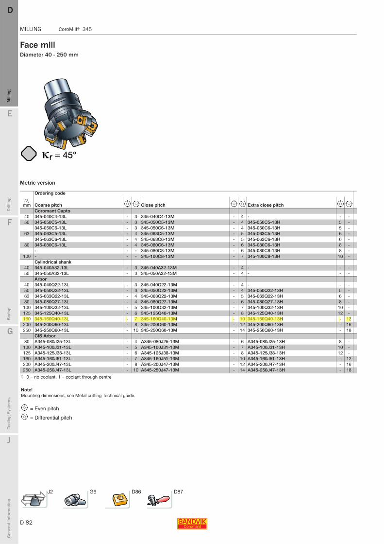
D 82
MILLING CoroMill® 345
E
Mill
ing
Drilli
ng
F
Bor
ing
G
Tool
ing
Syst
ems
J
Gen
eral
Info
rmat
ion
DDM
illin
g
MILLING CoroMill® 345
Face millDiameter 40 - 250 mm
Metric version
Ordering code
Dc mm Coarse pitch e i Close pitch e i Extra close pitch e i
Coromant Capto 40 345-040C4-13L - 3 345-040C4-13M - 4 - - -50 345-050C5-13L - 3 345-050C5-13M - 4 345-050C5-13H 5 -
345-050C6-13L - 3 345-050C6-13M - 4 345-050C6-13H 5 -63 345-063C5-13L - 4 345-063C5-13M - 5 345-063C5-13H 6 -
345-063C6-13L - 4 345-063C6-13M - 5 345-063C6-13H 6 -80 345-080C6-13L - 4 345-080C6-13M - 6 345-080C6-13H 8 -
- - - 345-080C8-13M - 6 345-080C8-13H 8 -100 - - - 345-100C8-13M - 7 345-100C8-13H 10 -
Cylindrical shank40 345-040A32-13L - 3 345-040A32-13M - 4 - - -50 345-050A32-13L - 3 345-050A32-13M - 4 - - -
Arbor40 345-040Q22-13L - 3 345-040Q22-13M - 4 - - -50 345-050Q22-13L - 3 345-050Q22-13M - 4 345-050Q22-13H 5 -63 345-063Q22-13L - 4 345-063Q22-13M - 5 345-063Q22-13H 6 -80 345-080Q27-13L - 4 345-080Q27-13M - 6 345-080Q27-13H 8 -
100 345-100Q32-13L - 5 345-100Q32-13M - 7 345-100Q32-13H 10 -125 345-125Q40-13L - 6 345-125Q40-13M - 8 345-125Q40-13H 12 -160 345-160Q40-13L - 7 345-160Q40-13M - 10 345-160Q40-13H - 12200 345-200Q60-13L - 8 345-200Q60-13M - 12 345-200Q60-13H - 16250 345-250Q60-13L - 10 345-250Q60-13M - 14 345-250Q60-13H - 18
CIS Arbor80 A345-080J25-13L - 4 A345-080J25-13M - 6 A345-080J25-13H 8 -
100 A345-100J31-13L - 5 A345-100J31-13M - 7 A345-100J31-13H 10 -125 A345-125J38-13L - 6 A345-125J38-13M - 8 A345-125J38-13H 12 -160 A345-160J51-13L - 7 A345-160J51-13M - 10 A345-160J51-13H - 12200 A345-200J47-13L - 8 A345-200J47-13M - 12 A345-200J47-13H - 16250 A345-250J47-13L - 10 A345-250J47-13M - 14 A345-250J47-13H - 18
1) 0 = no coolant, 1 = coolant through centre
Note!Mounting dimensions, see Metal cutting Technical guide.
e = Even pitch
i = Differential pitch
J2 G6 D86 D87

E
D 83
Mill
ing
Drilli
ng
F
Bor
ing
G
Tool
ing
Syst
ems
J
Gen
eral
Info
rmat
ion
DD
Mill
ing
CoroMill® 345 MILLING
MILLING CoroMill® 345
Coromant Capto® Arbor Cylindrical
l1 = programming length
Dimensions, mm
Extra close pitch plus e i Coolant1) U dmm D5m Dc2 l1 l2 l3 Max ap
1 0.6 40 54.08 60 6.01 0.9 50 64.08 60 6.01 1.3 63 64.08 60 6.01 1.1 50 78.08 60 6.01 1.4 63 77.08 60 6.01 2.0 63 94.08 70 6.01 2.8 80 94.08 70 6.01 3.7 80 114.08 80 6.0
1 0.8 32 54.08 120 40 6.01 1.0 32 64.08 120 40 6.0
1 0.3 22 54.08 45 6.01 0.4 22 64.08 45 6.0
345-063Q22-13HX 7 - 1 0.6 22 77.08 45 6.0345-080Q27-13HX 9 - 1 1.1 27 94.08 50 6.0345-100Q32-13HX 11 - 1 1.8 32 114.08 50 6.0345-125Q40-13HX 14 - 1 3.0 40 139.08 63 6.0345-160Q40-13HX 16 - 0 4.1 40 174.08 63 6.0345-200Q60-13HX 20 - 0 6.6 60 214.08 63 6.0345-250Q60-13HX 24 - 0 10.3 60 264.08 63 6.0
A345-080J25-13HX 9 - 1 0.9 25.4 94.08 50 6.0A345-100J31-13HX 11 - 1 1.8 31.75 114.08 63 6.0A345-125J38-13HX 14 - 1 3.2 38.1 139.08 63 6.0A345-160J51-13HX 16 - 0 4.7 50.8 174.08 63 6.0A345-200J47-13HX 20 - 0 6.6 47.625 214.08 63 6.0A345-250J47-13HX 24 - 0 11.7 47.625 264.08 63 6.0
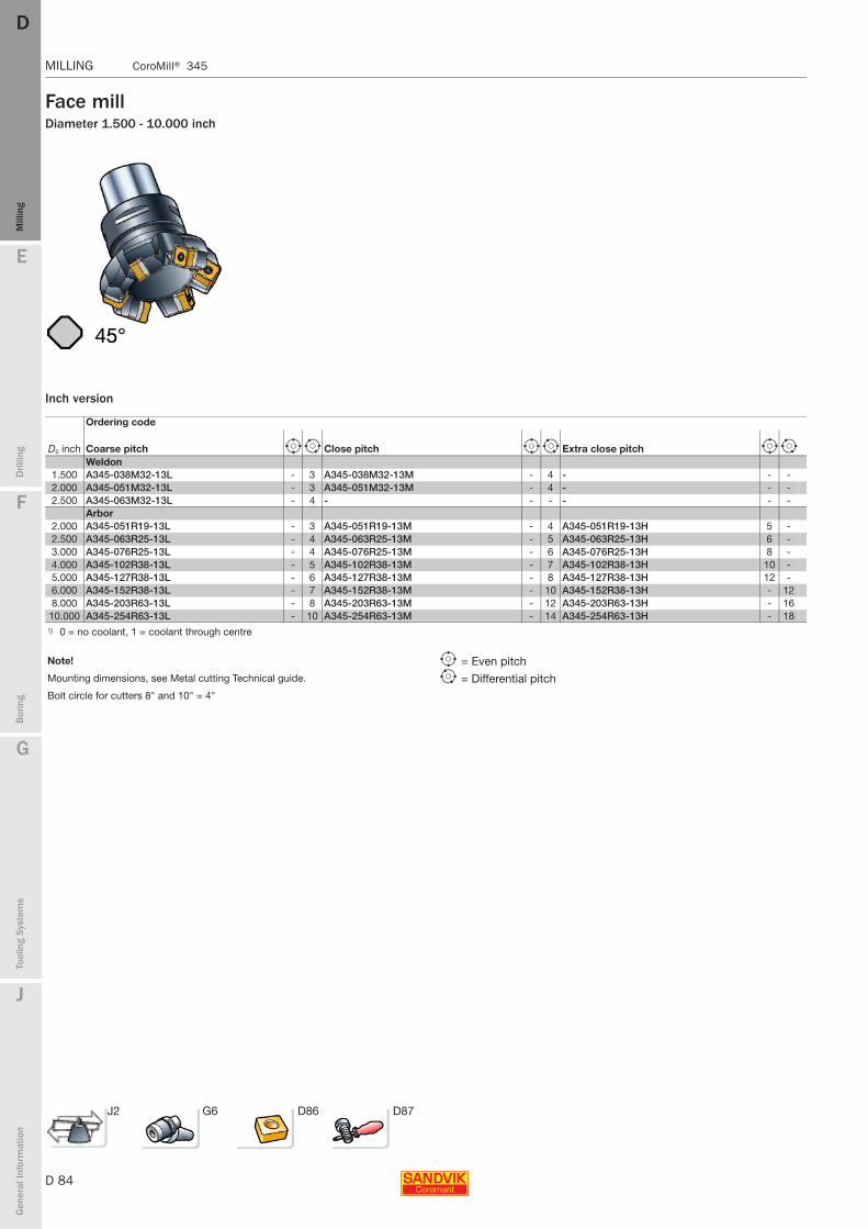
D 84
MILLING CoroMill® 345
E
Mill
ing
Drilli
ng
F
Bor
ing
G
Tool
ing
Syst
ems
J
Gen
eral
Info
rmat
ion
DDM
illin
g
MILLING CoroMill® 345
Face millDiameter 1.500 - 10.000 inch
Inch version
Ordering code
Dc inch Coarse pitch e i Close pitch e i Extra close pitch e i
Weldon1.500 A345-038M32-13L - 3 A345-038M32-13M - 4 - - -2.000 A345-051M32-13L - 3 A345-051M32-13M - 4 - - -2.500 A345-063M32-13L - 4 - - - - - -
Arbor2.000 A345-051R19-13L - 3 A345-051R19-13M - 4 A345-051R19-13H 5 -2.500 A345-063R25-13L - 4 A345-063R25-13M - 5 A345-063R25-13H 6 -3.000 A345-076R25-13L - 4 A345-076R25-13M - 6 A345-076R25-13H 8 -4.000 A345-102R38-13L - 5 A345-102R38-13M - 7 A345-102R38-13H 10 -5.000 A345-127R38-13L - 6 A345-127R38-13M - 8 A345-127R38-13H 12 -6.000 A345-152R38-13L - 7 A345-152R38-13M - 10 A345-152R38-13H - 128.000 A345-203R63-13L - 8 A345-203R63-13M - 12 A345-203R63-13H - 16
10.000 A345-254R63-13L - 10 A345-254R63-13M - 14 A345-254R63-13H - 181) 0 = no coolant, 1 = coolant through centre
Note! e = Even pitchMounting dimensions, see Metal cutting Technical guide. i = Differential pitchBolt circle for cutters 8" and 10" = 4"
J2 G6 D86 D87
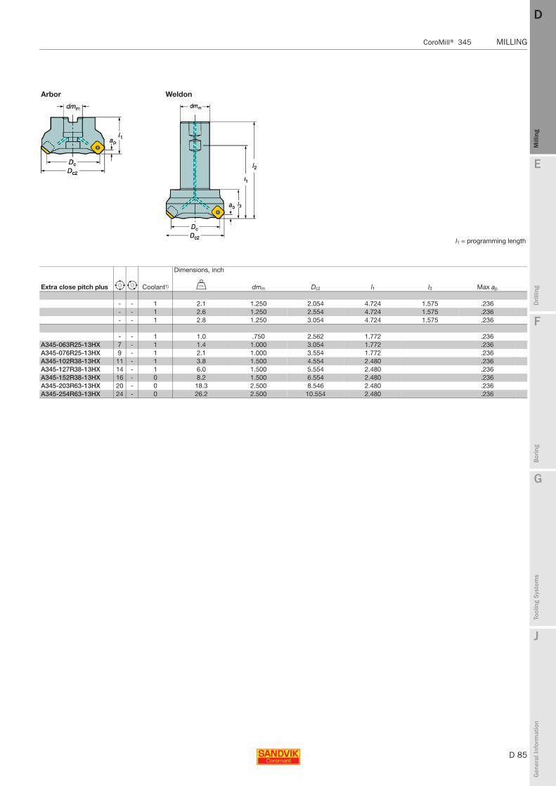
E
D 85
Mill
ing
Drilli
ng
F
Bor
ing
G
Tool
ing
Syst
ems
J
Gen
eral
Info
rmat
ion
DD
Mill
ing
CoroMill® 345 MILLING
MILLING CoroMill® 345
Arbor Weldon
l1 = programming length
Dimensions, inch
Extra close pitch plus e i Coolant1) V dmm Dc2 l1 l3 Max ap
- - 1 2.1 1.250 2.054 4.724 1.575 .236- - 1 2.6 1.250 2.554 4.724 1.575 .236- - 1 2.8 1.250 3.054 4.724 1.575 .236
- - 1 1.0 .750 2.562 1.772 .236A345-063R25-13HX 7 - 1 1.4 1.000 3.054 1.772 .236A345-076R25-13HX 9 - 1 2.1 1.000 3.554 1.772 .236A345-102R38-13HX 11 - 1 3.8 1.500 4.554 2.480 .236A345-127R38-13HX 14 - 1 6.0 1.500 5.554 2.480 .236A345-152R38-13HX 16 - 0 8.2 1.500 6.554 2.480 .236A345-203R63-13HX 20 - 0 18.3 2.500 8.546 2.480 .236A345-254R63-13HX 24 - 0 26.2 2.500 10.554 2.480 .236
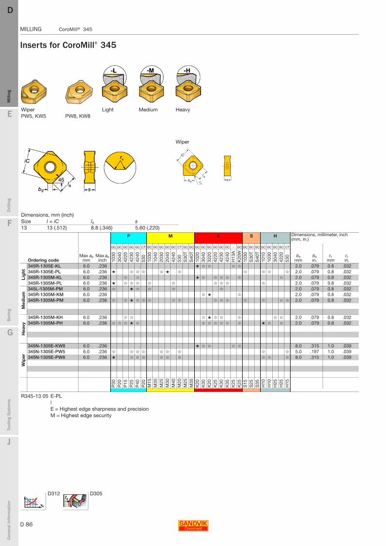
D 86
MILLING CoroMill® 345
E
Mill
ing
Drilli
ng
F
Bor
ing
G
Tool
ing
Syst
ems
J
Gen
eral
Info
rmat
ion
DDM
illin
g
MILLING CoroMill® 345
Inserts for CoroMill® 345
Wiper Light Medium HeavyPW5, KW5 PW8, KW8
Wiper
Dimensions, mm (inch)Size l = iC la s 13 13 (.512) 8.8 (.346) 5.60 (.220)
P M K S H Dimensions, millimeter, inch (mm, in.)
Ordering codeMax ap
mmMax ap
inch
GC GC GC GC GC CT GC GC GC GC GC CT GC GC GC GC GC GC GC GC - GC GC GC GC GC GC GC GC CT
bsmm
bsin.
rεmm
rεin.10
3030
4042
2042
3042
4053
010
3010
4020
3020
4042
4053
0S
30T
S40
T10
2030
4032
2042
2042
3042
40H
13A
K20
W10
30S
30T
S40
T10
1010
3030
4042
2053
0
Lig
ht
345R-1305E-KL 6.0 .236 ★ ✩ ✩ ✩ ✩ 2.0 .079 0.8 .032345R-1305E-PL 6.0 .236 ★ ✩ ✩ ✩ ✩ ★ ✩ ✩ ✩ ✩ ✩ 2.0 .079 0.8 .032345R-1305M-KL 6.0 .236 ✩ ✩ ★ ✩ ✩ ✩ ✩ ✩ ✩ 2.0 .079 0.8 .032345R-1305M-PL 6.0 .236 ★ ✩ ✩ ✩ ✩ ✩ ✩ ✩ ✩ ✩ 2.0 .079 0.8 .032
Med
ium
345L-1305M-PM 6.0 .236 ✩ ★ ✩ ✩ ✩ ✩ 2.0 .079 0.8 .032345R-1305M-KM 6.0 .236 ✩ ★ ✩ 2.0 .079 0.8 .032345R-1305M-PM 6.0 .236 ✩ ✩ ★ ✩ ✩ ✩ ✩ ✩ ✩ ✩ ✩ ✩ ✩ ✩ ✩ 2.0 .079 0.8 .032
Hea
vy
345R-1305M-KH 6.0 .236 ✩ ✩ ✩ ★ ✩ ✩ ✩ ✩ ✩ 2.0 .079 0.8 .032345R-1305M-PH 6.0 .236 ✩ ✩ ✩ ★ ✩ ✩ ✩ ✩ ✩ ✩ ✩ ★ ✩ ✩ 2.0 .079 0.8 .032
Wip
er
345N-1305E-KW8 6.0 .236 ★ ✩ ✩ ✩ ✩ 8.0 .315 1.0 .039345N-1305E-PW5 6.0 .236 ✩ ✩ ✩ ✩ ✩ ✩ ✩ ✩ ✩ 5.0 .197 1.0 .039345N-1305E-PW8 6.0 .236 ★ ✩ ✩ ✩ ✩ ✩ ✩ ✩ ✩ ✩ 8.0 .315 1.0 .039
P30
P20
P15
P25
P40
P20
M15
M35
M25
M30
M40
M20
M25
M35
K20
K30
K20
K25
K30
K35
K25
K25
S15
S25
S35
H10
H10
H25
H25
H15
R345-13 05 E-PL|E = Highest edge sharpness and precisionM = Highest edge security
D312 D305

E
D 87
Mill
ing
Drilli
ng
F
Bor
ing
G
Tool
ing
Syst
ems
J
Gen
eral
Info
rmat
ion
DD
Mill
ing
CoroMill® 345 MILLING
MILLING CoroMill® 345
Spare parts
Coolant screws
Cutter 1 2
Torque value
3 4 5
Insert size Insert screw Key (Torx Plus) Nm In-lbs Torque wrench1) Shim Shim screw Key (mm)13 416.1-834 5680 048-01 (15IP) 3.0 26 5680 100-06 5322 472-04 5512 090-11 3021 010-040 (4.0)
5322 473-012)
1) Optional part to be ordered separately.2) Shim for left hand cutter. Left hand cutters can be ordered as special.
Hex wrench
Fits following cutter codesScrew code Thread Size Key code Arbor sizeMetric 5512 073-01 M10 8 mm 3021 010-080 22 345-040Q22-13x
345-050Q22-13x5512 073-02 M12 10 mm 3021 010-100 27 345-080Q27-13x 5512 073-05 M14 14 mm 3021 010-140 32 345-100Q32-13x 5512 098-01 M20 50IP 5680 043-18 40 345-125Q40-13x
345-160Q40-13xInch 5512 074-01 3/8-24" 5/16" 3021 011-516 3/4 A345-051R19-13x
5512 074-02 1/2-20" 3/8" 3021 011-380 1.00 A345-063R25-13xA345-076R25-13x
5512 099-01 3/4-16" 50IP 5680 043-18 1.50 (B-Style) A345-102R38-13x5512 099-01 3/4-16" 50IP 5680 043-18 1.50 (B-Style) A345-127R38-13x5512 099-01 3/4-16" 50IP 5680 043-18 1.50 (B-Style) A345-152R38-13x5512 073-02 M12 10mm 3021 010-100 25.4 A345-080J25-13x5512 073-05 M14 14mm 3021 010-140 31.75 A345-100J31-13x5512 098-01 M20 50IP 5680 043-18 38.1 A345-125J38-13x
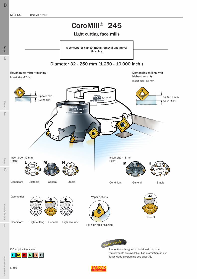
D 88
MILLING CoroMill® 245
E
Mill
ing
Drilli
ng
F
Bor
ing
G
Tool
ing
Syst
ems
J
Gen
eral
Info
rmat
ion
DDM
illin
g
MILLING CoroMill® 245
Insert size -12 mmPitch:
Condition: Unstable General Stable
Insert size -18 mmPitch:
Condition: General Stable
General
CoroMill® 245 Light cutting face mills
A concept for highest metal removal and mirror finishing
Diameter 32 - 250 mm (1.250 - 10.000 inch )
Roughing to mirror finishing
Insert size -12 mm
Up to 6 mm (.240 inch)
Demanding milling with highest security
Insert size -18 mm
Up to 10 mm (.394 inch)
Geometries:
Condition: Light cutting General High security
Wiper options
For high feed finishing
Tool options designed to individual customer requirements are available. For information on our Tailor Made programme see page J3.
ISO application areas:
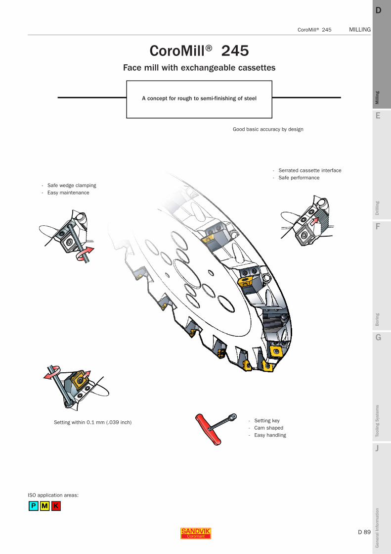
E
D 89
Mill
ing
Drilli
ng
F
Bor
ing
G
Tool
ing
Syst
ems
J
Gen
eral
Info
rmat
ion
DD
Mill
ing
CoroMill® 245 MILLING
MILLING CoroMill® 245
CoroMill® 245 Face mill with exchangeable cassettes
A concept for rough to semi-finishing of steel
- Safe wedge clamping- Easy maintenance
Setting within 0.1 mm (.039 inch)
ISO application areas:
Good basic accuracy by design
- Serrated cassette interface- Safe performance
- Setting key- Cam shaped- Easy handling

D 90
MILLING CoroMill® 245
E
Mill
ing
Drilli
ng
F
Bor
ing
G
Tool
ing
Syst
ems
J
Gen
eral
Info
rmat
ion
DDM
illin
g
MILLING CoroMill® 245
Face millDiameter 32 – 250 mm
Metric version
Arbor Cylindrical shank
l1 = programming length
Ordering code Dimensions, mm
K1)Dc
mm Coarse pitch i Close pitch e i Extra close pitch e i U dmm Dc2 l1 l2 l3Max ap nmax2)
Cylindrical shank12 32 - - R245-032A32-12M3) 3 - - - - 1.0 32.0 44.5 120 39 6 18250
40 R245-040A32-12L 3 - - - - - - 1.1 32.0 52.5 120 39 6 1825050 R245-050A32-12L 3 R245-050A32-12M 4 - - - - 1.4 32.0 62.5 120 39 6 1625063 R245-063A32-12L 4 R245-063A32-12M 5 - - - - 1.1 32.0 75.5 120 39 6 1440080 R245-080A32-12L 4 R245-080A32-12M 6 - - - - 2.1 32.0 92.5 120 39 6 12700
Arbor12 50 R245-050Q22-12L 3 R245-050Q22-12M 4 - R245-050Q22-12H 5 - 0.5 22.0 62.5 40 6 16250
63 R245-063Q22-12L 4 R245-063Q22-12M 5 - R245-063Q22-12H 6 - 0.6 22.0 75.5 40 6 1440080 R245-080Q27-12L 4 R245-080Q27-12M 6 - R245-080Q27-12H 8 - 1.0 27.0 92.5 50 6 12700
100 R245-100Q32-12L 5 R245-100Q32-12M 7 - R245-100Q32-12H 10 - 1.4 32.0 112.5 50 6 11300125 R245-125Q40-12L 6 R245-125Q40-12M 8 - R245-125Q40-12H 12 - 2.7 40.0 137.5 63 6 10100160 R245-160Q40-12L 7 R245-160Q40-12M 10 - R245-160Q40-12H 16 - 5.0 40.0 172.5 63 6 8900200 R245-200Q60-12L 8 R245-200Q60-12M 12 - R245-200Q60-12H 20 - 6.7 60.0 212.5 63 6 7950250 R245-250Q60-12L 10 R245-250Q60-12M 14 - R245-250Q60-12H 24 - 8.5 60.0 262.5 63 6 7100
18 80 - - R245-080Q32-18M3) - 4 R245-080Q32-18H - 5 1.6 32.0 98.8 50 10 6100100 - - R245-100Q32-18M3) - 4 R245-100Q32-18H - 6 1.9 32.0 118.8 50 10 5400125 - - R245-125Q40-18M - 5 R245-125Q40-18H - 7 3.6 40.0 138.8 63 10 4900160 - - R245-160Q40-18M - 6 R245-160Q40-18H - 9 8.7 40.0 178.8 63 10 4300200 - - R245-200Q60-18M - 8 R245-200Q60-18H - 12 12.0 60.0 218.8 63 10 3800250 - - R245-250Q60-18M - 10 R245-250Q60-18H - 14 8.9 60.0 268.8 63 10 3400
CIS Arbor12 80 RA245-080J25.4-12L 4 RA245-080J25.4-12M 6 - RA245-080J25.4-12H 8 - 1.2 25.4 92.5 50 6 12700
100 RA245-100J31.75-12L 5 RA245-100J31.75-12M 7 - RA245-100J31.75-12H 10 - 2.2 31.8 112.5 63 6 11300125 RA245-125J38.1-12L 6 RA245-125J38.1-12M 8 - RA245-125J38.1-12H 12 - 3.4 38.1 137.5 63 6 10100160 RA245-160J50.8-12L 7 RA245-160J50.8-12M 10 - RA245-160J50.8-12H 16 - 5.0 50.8 172.5 63 6 8900200 RA245-200J47.625-12L 8 RA245-200J47.625-12M 12 - RA245-200J47.625-12H 20 - 6.7 47.625 212.5 63 6 7950250 RA245-250J47.625-12L 10 RA245-250J47.625-12M 14 - - - - 8.5 47.625 262.5 63 6 7100
18 80 - - RA245-080J25-18M3) - 4 RA245-080J25-18H - 5 1.5 25.4 101.3 50 10 6100100 - - RA245-100J31-18M3) - 4 RA245-100J31-18H - 6 2.7 31.8 118.8 50 10 5400125 - - RA245-125J38-18M - 5 RA245-125J38-18H - 7 3.7 38.1 143.8 63 10 4900160 - - RA245-160J51-18M - 6 RA245-160J51-18H - 9 9.3 50.8 178.8 63 10 4300200 - - RA245-200J47-18M - 8 RA245-200J47-18H - 12 12.0 47.625 218.8 63 10 3800250 - - RA245-250J47-18M - 10 RA245-250J47-18H - 14 8.9 47.625 268.8 63 10 3400
1) Inserts are ordered separately.2) nmax (max. rev/min) for holders must also be considered.3) Without shim
Note!Mounting dimensions, see Metal cutting Technical guide.Bolt circle for cutters 200 and 250mm = 4"
e = Even pitch
i = Differential pitch
D93 D95 G6 D2 J3

E
D 91
Mill
ing
Drilli
ng
F
Bor
ing
G
Tool
ing
Syst
ems
J
Gen
eral
Info
rmat
ion
DD
Mill
ing
CoroMill® 245 MILLING
MILLING CoroMill® 245
Face millDiameter 1.250 - 10.000 inch
Inch version
Arbor Weldon/Whistle Notch
l1 = programming length
Ordering code Dimensions, inch
K1) Dc inch Coarse pitch i Close pitch e i Extra close pitch e i V dmm Dc2 l1 l2 l3Max ap nmax2)
Whistle Notch/Weldon12 1.250 RA245-032MN25-12L 2 RA245-032MN25-12M 3 - - - - 1.6 1.000 1.742 2.716 3.856 1.575 .240 18250
1.500 RA245-038MN32-12L 3 RA245-038MN32-12M 4 - - - - 1.9 1.250 1.992 2.716 3.856 1.575 .240 182502.000 RA245-051MN32-12L 3 RA245-051MN32-12M 4 - - - - 3.1 1.250 2.492 2.834 3.974 1.575 .240 162502.500 RA245-063MN32-12L 4 RA245-063MN32-12M 5 - - - - 3.3 1.250 2.992 2.834 3.974 1.575 .240 14400
Arbor12 2.000 RA245-051R19-12L 3 RA245-051R19-12M 4 - RA245-051R19-12H 5 - 1.1 .750 2.492 1.575 .240 16250
2.500 RA245-063R19-12L 4 RA245-063R19-12M 5 - RA245-063R19-12H 6 - 1.6 .750 2.992 1.575 .240 144003.000 RA245-076R25-12L 4 RA245-076R25-12M 6 - RA245-076R25-12H 8 - 2.2 1.000 3.492 1.969 .240 127004.000 RA245-102R38-12L 5 RA245-102R38-12M 7 - RA245-102R38-12H 10 - 6.8 1.500 4.492 1.969 .240 113005.000 RA245-127R38-12L 6 RA245-127R38-12M 8 - RA245-127R38-12H 12 - 12.1 1.500 5.492 2.480 .240 101006.000 RA245-152R38-12L 7 RA245-152R38-12M 10 - RA245-152R38-12H 15 - 18.7 1.500 6.492 2.480 .240 89008.000 RA245-203R63-12L 8 RA245-203R63-12M 12 - RA245-203R63-12H 20 - 14.8 2.500 8.492 2.480 .240 7950
10.000 RA245-254R63-12L 10 RA245-254R63-12M 14 - RA245-254R63-12H 24 - 29.6 2.500 10.492 2.480 .240 710018 3.000 - - RA245-076R25-18M - 4 RA245-076R25-18H - 5 3.1 1.000 3.740 1.969 .394 6300
4.000 - - RA245-102R38-18M - 4 RA245-102R38-18H - 6 7.7 1.500 4.740 1.969 .394 54005.000 - - RA245-127R38-18M - 5 RA245-127R38-18H - 7 14.1 1.500 5.740 2.480 .394 48006.000 - - RA245-152R38-18M - 6 RA245-152R38-18H - 9 20.5 1.500 6.740 2.480 .394 44008.000 - - RA245-203R63-18M - 8 RA245-203R63-18H - 12 32.6 2.500 8.740 2.480 .394 3800
10.000 - - RA245-254R63-18M - 10 RA245-254R63-18H - 14 54.5 2.500 10.740 2.480 .394 34001) Inserts are ordered separately.2) nmax (max. rev/min) for holders must also be considered.
Note!Mounting dimensions, see Metal cutting Technical guide.Bolt circle for cutters 8" and 10" = 4"
e = Even pitch
i = Differential pitch
D93 D95 G6 D2 J3
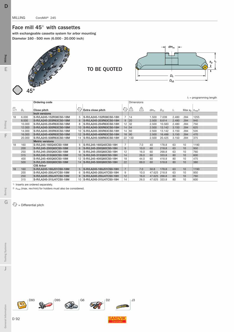
D 92
MILLING CoroMill® 245
E
Mill
ing
Drilli
ng
F
Bor
ing
G
Tool
ing
Syst
ems
J
Gen
eral
Info
rmat
ion
DDM
illin
g
MILLING CoroMill® 245
Face mill 45° with cassetteswith exchangeable cassette system for arbor mountingDiameter 160 - 500 mm (6.000 - 20.000 inch)
TO BE QUOTED
l1 = programming length
Ordering code Dimensions
K1) Dc Close pitch i Extra close pitch i V U dmm Dc2 l1 Max ap nmax2)
Inch versions18 6.000 S-R/LA245-152R38CS0-18M 5 S-R/LA245-152R38CS0-18H 7 14 1.500 7.039 2.480 .394 1255
8.000 S-R/LA245-203R63CS0-18M 6 S-R/LA245-203R63CS0-18H 9 20 2.500 8.614 2.480 .394 94010.000 S-R/LA245-254R63CS0-18M 8 S-R/LA245-254R63CS0-18H 12 32 2.500 10.583 2.480 .394 75012.000 S-R/LA245-305R63CS0-18M 10 S-R/LA245-305R63CS0-18H 14 54 2.500 13.142 3.150 .394 62514.000 S-R/LA245-355R63CS0-18M 10 S-R/LA245-355R63CS0-18H 14 60 2.500 13.142 3.150 .394 53516.000 S-R/LA245-406R63CS0-18M 12 S-R/LA245-406R63CS0-18H 18 90 2.500 16.488 3.150 .394 47020.000 S-R/LA245-508R63CS0-18M 14 S-R/LA245-508R63CS0-18H 22 130 2.500 20.425 3.150 .394 375
Metric versions18 160 S-R/L245-160Q40CS0-18M 5 S-R/L245-160Q40CS0-18H 7 7.0 40 178.8 63 10 1190
200 S-R/L245-200Q60CS0-18M 6 S-R/L245-200Q60CS0-18H 9 10.0 60 218.8 63 10 950250 S-R/L245-250Q60CS0-18M 8 S-R/L245-250Q60CS0-18H 12 16.0 60 268.8 63 10 760315 S-R/L245-315Q60CS0-18M 10 S-R/L245-315Q60CS0-18H 14 26.0 60 333.8 80 10 600400 S-R/L245-400Q60CS0-18M 12 S-R/L245-400Q60CS0-18H 18 44.0 60 418.8 80 10 475500 S-R/L245-500Q60CS0-18M 14 S-R/L245-500Q60CS0-18H 22 69.0 60 518.8 80 10 380
CIS Arbor18 160 S-R/LA245-160J51CS0-18M 5 S-R/LA245-160J51CS0-18H 7 7.0 50.8 178.8 63 10 1190
200 S-R/LA245-200J47CS0-18M 6 S-R/LA245-200J47CS0-18H 9 10.0 47.625 218.8 63 10 950250 S-R/LA245-250J47CS0-18M 8 S-R/LA245-250J47CS0-18H 12 16.0 47.625 268.8 63 10 760315 S-R/LA245-315J47CS0-18M 10 S-R/LA245-315J47CS0-18H 14 26.0 47.625 333.8 80 10 600
1) Inserts are ordered separately.2) nmax (max. rev/min) for holders must also be considered.
i = Differential pitch
D93 D95 G6 D2 J3
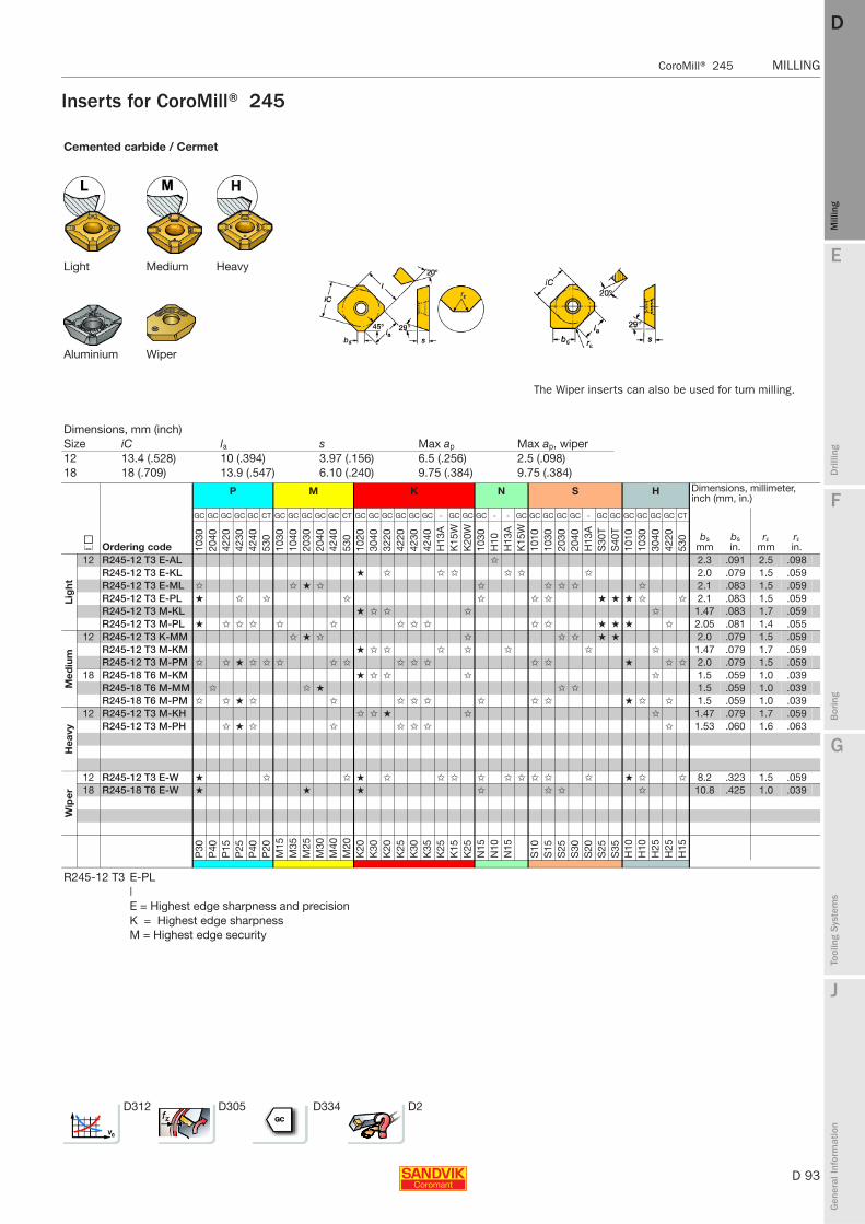
E
D 93
Mill
ing
Drilli
ng
F
Bor
ing
G
Tool
ing
Syst
ems
J
Gen
eral
Info
rmat
ion
DD
Mill
ing
CoroMill® 245 MILLING
MILLING CoroMill® 245
Inserts for CoroMill® 245
Cemented carbide / Cermet
Light Medium Heavy
Aluminium Wiper
The Wiper inserts can also be used for turn milling.
Dimensions, mm (inch)Size iC la s Max ap Max ap, wiper12 13.4 (.528) 10 (.394) 3.97 (.156) 6.5 (.256) 2.5 (.098)18 18 (.709) 13.9 (.547) 6.10 (.240) 9.75 (.384) 9.75 (.384)
P M K N S H Dimensions, millimeter, inch (mm, in.)
J Ordering code
GC GC GC GC GC CT GC GC GC GC GC CT GC GC GC GC GC GC - GC GC GC - - GC GC GC GC GC - GC GC GC GC GC GC CT
bsmm
bsin.
rεmm
rεin.10
3020
4042
2042
3042
4053
010
3010
4020
3020
4042
4053
010
2030
4032
2042
2042
3042
40H
13A
K15
WK
20W
1030
H10
H13
AK
15W
1010
1030
2030
2040
H13
AS
30T
S40
T10
1010
3030
4042
2053
0
Lig
ht
12 R245-12 T3 E-AL ✩ 2.3 .091 2.5 .098R245-12 T3 E-KL ★ ✩ ✩ ✩ ✩ ✩ ✩ 2.0 .079 1.5 .059R245-12 T3 E-ML ✩ ✩ ★ ✩ ✩ ✩ ✩ ✩ ✩ 2.1 .083 1.5 .059R245-12 T3 E-PL ★ ✩ ✩ ✩ ✩ ✩ ✩ ★ ★ ★ ✩ ✩ 2.1 .083 1.5 .059R245-12 T3 M-KL ★ ✩ ✩ ✩ ✩ 1.47 .083 1.7 .059R245-12 T3 M-PL ★ ✩ ✩ ✩ ✩ ✩ ✩ ✩ ✩ ✩ ✩ ★ ★ ★ ✩ 2.05 .081 1.4 .055
Med
ium
12 R245-12 T3 K-MM ✩ ★ ✩ ✩ ✩ ✩ ★ ★ 2.0 .079 1.5 .059R245-12 T3 M-KM ★ ✩ ✩ ✩ ✩ ✩ ✩ ✩ 1.47 .079 1.7 .059R245-12 T3 M-PM ✩ ✩ ★ ✩ ✩ ✩ ✩ ✩ ✩ ✩ ✩ ✩ ✩ ★ ✩ ✩ 2.0 .079 1.5 .059
18 R245-18 T6 M-KM ★ ✩ ✩ ✩ ✩ 1.5 .059 1.0 .039R245-18 T6 M-MM ✩ ✩ ★ ✩ ✩ 1.5 .059 1.0 .039R245-18 T6 M-PM ✩ ✩ ★ ✩ ✩ ✩ ✩ ✩ ✩ ✩ ✩ ★ ✩ ✩ 1.5 .059 1.0 .039
Hea
vy
12 R245-12 T3 M-KH ✩ ✩ ★ ✩ ✩ 1.47 .079 1.7 .059R245-12 T3 M-PH ✩ ★ ✩ ✩ ✩ ✩ ✩ ✩ 1.53 .060 1.6 .063
Wip
er
12 R245-12 T3 E-W ★ ✩ ✩ ★ ✩ ✩ ✩ ✩ ✩ ✩ ✩ ✩ ✩ ★ ✩ ✩ 8.2 .323 1.5 .05918 R245-18 T6 E-W ★ ★ ★ ✩ ✩ ✩ ✩ 10.8 .425 1.0 .039
P30
P40
P15
P25
P40
P20
M15
M35
M25
M30
M40
M20
K20
K30
K20
K25
K30
K35
K25
K15
K25
N15
N10
N15
S10
S15
S25
S30
S20
S25
S35
H10
H10
H25
H25
H15
R245-12 T3 E-PL|E = Highest edge sharpness and precisionK = Highest edge sharpnessM = Highest edge security
D312 D305 D334 D2
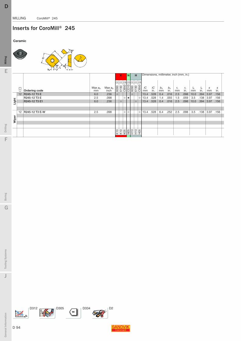
D 94
MILLING CoroMill® 245
E
Mill
ing
Drilli
ng
F
Bor
ing
G
Tool
ing
Syst
ems
J
Gen
eral
Info
rmat
ion
DDM
illin
g
MILLING CoroMill® 245
Inserts for CoroMill® 245
Ceramic
K N H Dimensions, millimeter, inch (mm, in.)
J Ordering codeMax ap
mmMax ap
inch
CC CC CB CD CC CC CB
iCmm
iCin.
bsmm
bsin.
rεmm
rεin.
lamm
lain.
smm
sin.60
9061
90C
B50
CD
1060
9061
90C
B50
Lig
ht
12 R245-12 T3 E 6.0 .236 ✩ ✩ 13.4 .528 0.4 .016 2.5 .098 10.0 .394 3.97 .156R245-12 T3 E 2.5 .098 ✩ ★ ✩ 13.4 .528 1.4 .055 1.5 .059 3.5 .138 3.97 .156R245-12 T3 E1 6.0 .236 ✩ ✩ 13.4 .528 0.4 .016 2.5 .098 10.0 .394 3.97 .156
Wip
er
12 R245-12 T3 E-W 2.5 .098 ✩ ✩ ✩ 13.4 .528 6.4 .252 2.5 .098 3.5 .138 3.97 .156
K10
K10
K05
N05
H10
H10
H05
D312 D305 D334 D2
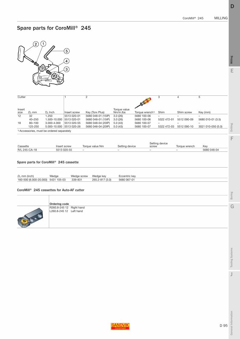
E
D 95
Mill
ing
Drilli
ng
F
Bor
ing
G
Tool
ing
Syst
ems
J
Gen
eral
Info
rmat
ion
DD
Mill
ing
CoroMill® 245 MILLING
MILLING CoroMill® 245
Spare parts for CoroMill® 245
Spare parts for CoroMill® 245 cassette
CoroMill® 245 cassettes for Auto-AF cutter
Cutter 1 2 3 4 5
Insert size Dc mm Dc Inch Insert screw Key (Torx Plus)
Torque value Nm/in.lbs Torque wrench1) Shim Shim screw Key (mm)
12 32 1.250 5513 020-01 5680 048-01 (15IP) 3.0 (26) 5680 100-06 – – –40–250 1.500-10.000 5513 020-01 5680 048-01 (15IP) 3.0 (26) 5680 100-06 5322 472-01 5512 090-09 5680 010-01 (3.5)
18 80–100 3.000-4.000 5513 020-55 5680 048-04 (20IP) 5.0 (43) 5680 100-07 – – –125-250 5.000-10.000 5513 020-26 5680 048-04 (20IP) 5.0 (43) 5680 100-07 5322 472-03 5512 090-10 3021 010-050 (5.0)
1) Accessories, must be ordered separately
Cassette Insert screw Torque value Nm Setting deviceSetting device screw Torque wrench Key
R/L 245-CA-18 5513 020-55 – – – – 5680 048-04
Dc mm (inch) Wedge Wedge screw Wedge key Eccentric key160-500 (6.000-20.000) 5431 105-03 339-831 265.2-817 (3.0) 5680 067-01
Ordering codeR260.8-245 12 Right handL260.8-245 12 Left hand
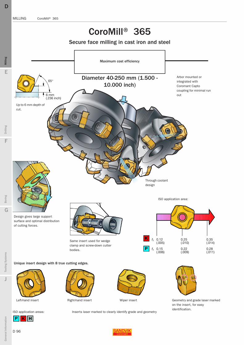
D 96
MILLING CoroMill® 365
E
Mill
ing
Drilli
ng
F
Bor
ing
G
Tool
ing
Syst
ems
J
Gen
eral
Info
rmat
ion
DDM
illin
g
MILLING CoroMill® 365
CoroMill® 365Secure face milling in cast iron and steel
Maximum cost efficiency
Diameter 40-250 mm (1.500 - 10.000 inch)
Through coolant design
Arbor mounted or integrated with Coromant Capto coupling for minimal run out
Design gives large support surface and optimal distribution of cutting forces.
Up to 6 mm depth of cut.
Left-hand insert Right-hand insert
ISO application area:
Unique insert design with 8 true cutting edges.
65°
6 mm(.236 inch)
fz 0.12 (.005)
0.25 (.010)
0.35 (.014)
fz 0.15 (.006)
0.22 (.009)
0.28 (.011)
Geometry and grade laser marked on the insert, for easy identification.
Wiper insert
Same insert used for wedge clamp and screw-down cutter bodies.
Inserts laser marked to clearly identify grade and geometryISO application areas:
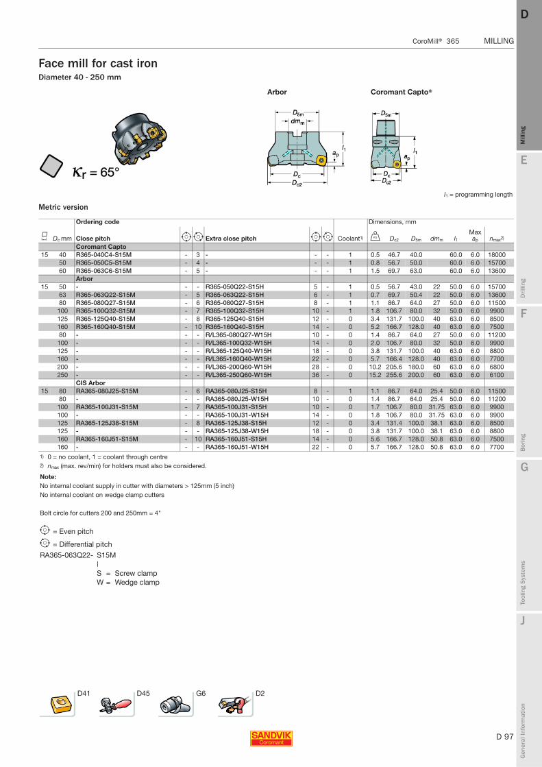
E
D 97
Mill
ing
Drilli
ng
F
Bor
ing
G
Tool
ing
Syst
ems
J
Gen
eral
Info
rmat
ion
DD
Mill
ing
CoroMill® 365 MILLING
MILLING CoroMill® 365
Face mill for cast ironDiameter 40 - 250 mm
Metric version
Arbor Coromant Capto®
l1 = programming length
Ordering code Dimensions, mm
K Dc mm Close pitch e i Extra close pitch e i Coolant1) U Dc2 D5m dmm l1Max ap nmax2)
Coromant Capto 15 40 R365-040C4-S15M - 3 - - - 1 0.5 46.7 40.0 60.0 6.0 18000
50 R365-050C5-S15M - 4 - - - 1 0.8 56.7 50.0 60.0 6.0 1570060 R365-063C6-S15M - 5 - - - 1 1.5 69.7 63.0 60.0 6.0 13600
Arbor15 50 - - - R365-050Q22-S15H 5 - 1 0.5 56.7 43.0 22 50.0 6.0 15700
63 R365-063Q22-S15M - 5 R365-063Q22-S15H 6 - 1 0.7 69.7 50.4 22 50.0 6.0 1360080 R365-080Q27-S15M - 6 R365-080Q27-S15H 8 - 1 1.1 86.7 64.0 27 50.0 6.0 11500
100 R365-100Q32-S15M - 7 R365-100Q32-S15H 10 - 1 1.8 106.7 80.0 32 50.0 6.0 9900125 R365-125Q40-S15M - 8 R365-125Q40-S15H 12 - 0 3.4 131.7 100.0 40 63.0 6.0 8500160 R365-160Q40-S15M - 10 R365-160Q40-S15H 14 - 0 5.2 166.7 128.0 40 63.0 6.0 750080 - - - R/L365-080Q27-W15H 10 - 0 1.4 86.7 64.0 27 50.0 6.0 11200
100 - - - R/L365-100Q32-W15H 14 - 0 2.0 106.7 80.0 32 50.0 6.0 9900125 - - - R/L365-125Q40-W15H 18 - 0 3.8 131.7 100.0 40 63.0 6.0 8800160 - - - R/L365-160Q40-W15H 22 - 0 5.7 166.4 128.0 40 63.0 6.0 7700200 - - - R/L365-200Q60-W15H 28 - 0 10.2 205.6 180.0 60 63.0 6.0 6800250 - - - R/L365-250Q60-W15H 36 - 0 15.2 255.6 200.0 60 63.0 6.0 6100
CIS Arbor15 80 RA365-080J25-S15M - 6 RA365-080J25-S15H 8 - 1 1.1 86.7 64.0 25.4 50.0 6.0 11500
80 - - - RA365-080J25-W15H 10 - 0 1.4 86.7 64.0 25.4 50.0 6.0 11200100 RA365-100J31-S15M - 7 RA365-100J31-S15H 10 - 0 1.7 106.7 80.0 31.75 63.0 6.0 9900100 - - - RA365-100J31-W15H 14 - 0 1.8 106.7 80.0 31.75 63.0 6.0 9900125 RA365-125J38-S15M - 8 RA365-125J38-S15H 12 - 0 3.4 131.4 100.0 38.1 63.0 6.0 8500125 - - - RA365-125J38-W15H 18 - 0 3.8 131.7 100.0 38.1 63.0 6.0 8800160 RA365-160J51-S15M - 10 RA365-160J51-S15H 14 - 0 5.6 166.7 128.0 50.8 63.0 6.0 7500160 - - - RA365-160J51-W15H 22 - 0 5.7 166.7 128.0 50.8 63.0 6.0 7700
1) 0 = no coolant, 1 = coolant through centre2) nmax (max. rev/min) for holders must also be considered.
Note:No internal coolant supply in cutter with diameters > 125mm (5 inch)No internal coolant on wedge clamp cutters
Bolt circle for cutters 200 and 250mm = 4"
e = Even pitch
i = Differential pitch
RA365-063Q22- S15M| S = Screw clampW = Wedge clamp
D41 D45 G6 D2
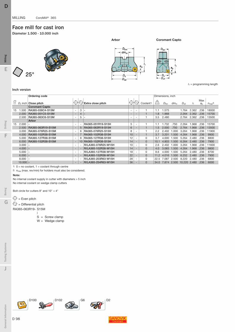
D 98
MILLING CoroMill® 365
E
Mill
ing
Drilli
ng
F
Bor
ing
G
Tool
ing
Syst
ems
J
Gen
eral
Info
rmat
ion
DDM
illin
g
MILLING CoroMill® 365
Face mill for cast ironDiameter 1.500 - 10.000 inch
Inch version
Arbor Coromant Capto
l1 = programming length
Ordering code Dimensions, inch
K Dc inch Close pitch e i Extra close pitch e i Coolant1) V D5m dmm Dc2 l1Max ap nmax2)
Coromant Capto 15 1.500 RA365-038C4-S15M - 3 - - - 1 1.1 1.575 1.764 2.362 .236 18000
2.000 RA365-051C5-S15M - 4 - - - 1 1.8 1.968 2.264 2.362 .236 157002.500 RA365-063C6-S15M - 5 - - - 1 3.5 2.480 2.764 2.362 .236 13500
Arbor15 2.000 - - - RA365-051R19-S15H 5 - 1 1.1 1.732 .750 2.264 1.968 .236 15700
2.500 RA365-063R19-S15M - 5 RA365-063R19-S15H 6 - 1 1.5 2.000 .750 2.764 1.968 .236 135003.000 RA365-076R25-S15M - 6 RA365-076R25-S15H 8 - 1 2.2 2.402 1.000 3.264 1.968 .236 119004.000 RA365-102R38-S15M - 7 RA365-102R38-S15H 10 - 1 3.7 3.201 1.500 4.264 1.968 .236 99005.000 RA365-127R38-S15M - 8 RA365-127R38-S15H 12 - 0 3.7 4.000 1.500 5.264 2.480 .236 88006.000 RA365-152R38-S15M - 10 RA365-152R38-S15H 14 - 0 10.1 4.803 1.500 6.264 2.480 .236 79003.000 - - - R/LA365-076R25-W15H 10 - 0 2.6 2.402 1.000 3.264 1.968 .236 116004.000 - - - R/LA365-102R38-W15H 14 - 0 4.0 3.083 1.500 4.264 1.968 .236 98005.000 - - - R/LA365-127R38-W15H 18 - 0 8.6 4.000 1.500 5.264 2.480 .236 87006.000 - - - R/LA365-152R38-W15H 22 - 0 11.2 4.016 1.500 6.252 2.480 .236 79008.000 - - - R/LA365-203R63-W15H 28 - 0 22.5 7.087 2.500 8.220 2.480 .236 6800
10.000 - - - R/LA365-254R63-W15H 36 - 0 34.0 7.874 2.500 10.220 2.480 .236 60001) 0 = no coolant, 1 = coolant through centre2) nmax (max. rev/min) for holders must also be considered.
Note:No internal coolant supply in cutter with diameters > 5 inchNo internal coolant on wedge clamp cutters
Bolt circle for cutters 8" and 10" = 4"
e = Even pitch
i = Differential pitch
RA365-063R19- S15M| S = Screw clampW = Wedge clamp
D100 D102 G6 D2
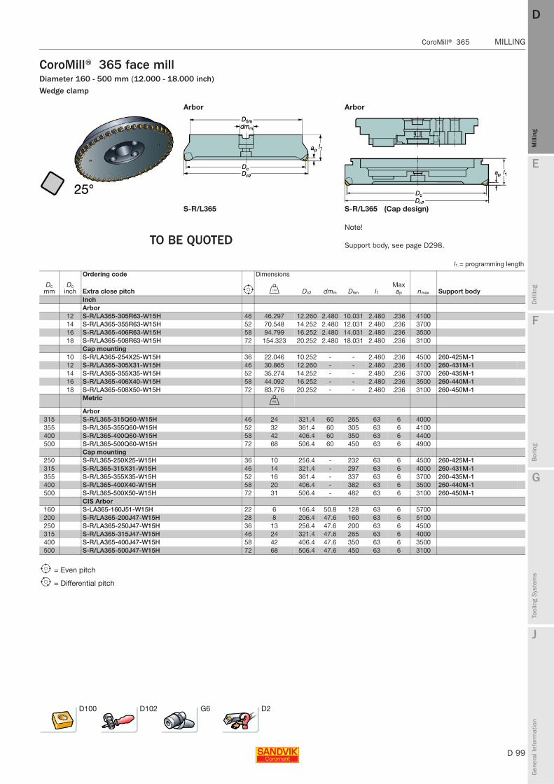
E
D 99
Mill
ing
Drilli
ng
F
Bor
ing
G
Tool
ing
Syst
ems
J
Gen
eral
Info
rmat
ion
DD
Mill
ing
CoroMill® 365 MILLING
MILLING CoroMill® 365
CoroMill® 365 face millDiameter 160 - 500 mm (12.000 - 18.000 inch)Wedge clamp
Arbor Arbor
S-R/L365 S-R/L365 (Cap design)
TO BE QUOTEDNote!
Support body, see page D298.
l1 = programming length
Ordering code Dimensions
Dc mm
Dc inch Extra close pitch e V Dc2 dmm D5m l1
Max ap nmax Support body
Inch Arbor
12 S-R/LA365-305R63-W15H 46 46.297 12.260 2.480 10.031 2.480 .236 410014 S-R/LA365-355R63-W15H 52 70.548 14.252 2.480 12.031 2.480 .236 370016 S-R/LA365-406R63-W15H 58 94.799 16.252 2.480 14.031 2.480 .236 350018 S-R/LA365-508R63-W15H 72 154.323 20.252 2.480 18.031 2.480 .236 3100
Cap mounting10 S-R/LA365-254X25-W15H 36 22.046 10.252 - - 2.480 .236 4500 260-425M-112 S-R/LA365-305X31-W15H 46 30.865 12.260 - - 2.480 .236 4100 260-431M-114 S-R/LA365-355X35-W15H 52 35.274 14.252 - - 2.480 .236 3700 260-435M-116 S-R/LA365-406X40-W15H 58 44.092 16.252 - - 2.480 .236 3500 260-440M-118 S-R/LA365-508X50-W15H 72 83.776 20.252 - - 2.480 .236 3100 260-450M-1
MetricU
Arbor315 S-R/L365-315Q60-W15H 46 24 321.4 60 265 63 6 4000355 S-R/L365-355Q60-W15H 52 32 361.4 60 305 63 6 4100400 S-R/L365-400Q60-W15H 58 42 406.4 60 350 63 6 4400500 S-R/L365-500Q60-W15H 72 68 506.4 60 450 63 6 4900
Cap mounting250 S-R/L365-250X25-W15H 36 10 256.4 - 232 63 6 4500 260-425M-1315 S-R/L365-315X31-W15H 46 14 321.4 - 297 63 6 4000 260-431M-1355 S-R/L365-355X35-W15H 52 16 361.4 - 337 63 6 3700 260-435M-1400 S-R/L365-400X40-W15H 58 20 406.4 - 382 63 6 3500 260-440M-1500 S-R/L365-500X50-W15H 72 31 506.4 - 482 63 6 3100 260-450M-1
CIS Arbor160 S-LA365-160J51-W15H 22 6 166.4 50.8 128 63 6 5700200 S-R/LA365-200J47-W15H 28 8 206.4 47.6 160 63 6 5100250 S-R/LA365-250J47-W15H 36 13 256.4 47.6 200 63 6 4500315 S-R/LA365-315J47-W15H 46 24 321.4 47.6 265 63 6 4000400 S-R/LA365-400J47-W15H 58 42 406.4 47.6 350 63 6 3500500 S-R/LA365-500J47-W15H 72 68 506.4 47.6 450 63 6 3100
e = Even pitch
i = Differential pitch
D100 D102 G6 D2
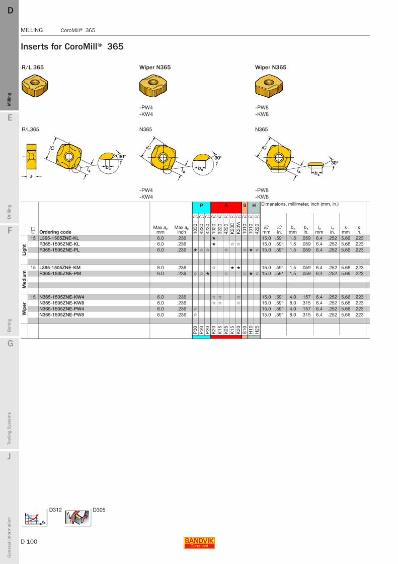
D 100
MILLING CoroMill® 365
E
Mill
ing
Drilli
ng
F
Bor
ing
G
Tool
ing
Syst
ems
J
Gen
eral
Info
rmat
ion
DDM
illin
g
MILLING CoroMill® 365
Inserts for CoroMill® 365
R/L 365 Wiper N365 Wiper N365
-PW4 -PW8-KW4 -KW8
R/L365 N365 N365
-PW4 -PW8-KW4 -KW8
P K S H Dimensions, millimeter, inch (mm, in.)
J Ordering codeMax ap
mmMax ap
inch
GC GC GC GC GC GC GC GC GC GC GC
iCmm
iCin.
bsmm
bsin.
lamm
lain.
smm
sin.10
3042
2042
3010
2032
2042
20K
20D
K20
W10
1010
1042
20
Lig
ht
15 L365-1505ZNE-KL 6.0 .236 ★ 15.0 .591 1.5 .059 6.4 .252 5.66 .223R365-1505ZNE-KL 6.0 .236 ★ ✩ ✩ 15.0 .591 1.5 .059 6.4 .252 5.66 .223R365-1505ZNE-PL 6.0 .236 ★ ✩ ✩ ✩ ✩ ★ ✩ 15.0 .591 1.5 .059 6.4 .252 5.66 .223
Med
ium
15 L365-1505ZNE-KM 6.0 .236 ✩ ★ ★ 15.0 .591 1.5 .059 6.4 .252 5.66 .223R365-1505ZNE-PM 6.0 .236 ✩ ✩ ★ ✩ ✩ ★ ✩ 15.0 .591 1.5 .059 6.4 .252 5.66 .223
Wip
er
15 N365-1505ZNE-KW4 6.0 .236 ✩ ✩ ✩ 15.0 .591 4.0 .157 6.4 .252 5.66 .223N365-1505ZNE-KW8 6.0 .236 ✩ ✩ ✩ 15.0 .591 8.0 .315 6.4 .252 5.66 .223N365-1505ZNE-PW4 6.0 .236 ✩ 15.0 .591 4.0 .157 6.4 .252 5.66 .223N365-1505ZNE-PW8 6.0 .236 ✩ 15.0 .591 8.0 .315 6.4 .252 5.66 .223
P30
P20
P20
K20
K15
K25
K15
K20
S10
H10
H25
D312 D305
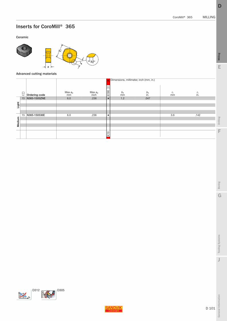
E
D 101
Mill
ing
Drilli
ng
F
Bor
ing
G
Tool
ing
Syst
ems
J
Gen
eral
Info
rmat
ion
DD
Mill
ing
CoroMill® 365 MILLING
MILLING CoroMill® 365
Inserts for CoroMill® 365
Ceramic
Advanced cutting materials
K Dimensions, millimeter, inch (mm, in.)
J Ordering codeMax ap
mmMax ap
inch
CC
bsmm
bsin.
rεmm
rεin.61
90
Lig
ht
15 N365-1505ZNE 6.0 .236 ★ 1.2 .047
Med
ium
15 N365-150536E 6.0 .236 ★ 3.6 .142
K10
D312 D305
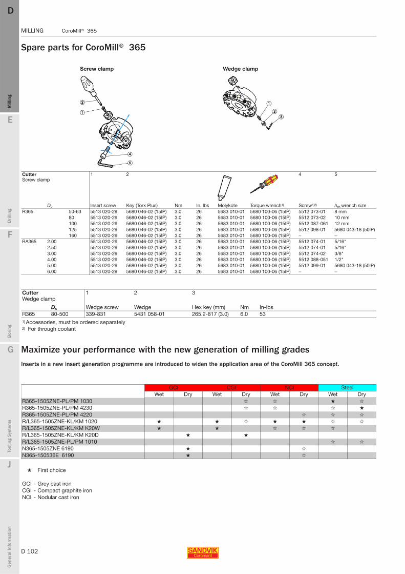
D 102
MILLING CoroMill® 365
E
Mill
ing
Drilli
ng
F
Bor
ing
G
Tool
ing
Syst
ems
J
Gen
eral
Info
rmat
ion
DDM
illin
g
MILLING CoroMill® 365
Spare parts for CoroMill® 365
Maximize your performance with the new generation of milling gradesInserts in a new insert generation programme are introduced to widen the application area of the CoroMill 365 concept.
Screw clamp Wedge clamp
Cutter 1 2 4 5Screw clamp
Insert screwDc Key (Torx Plus) Nm In. lbs Molykote Torque wrench1) Screw1)2) hex wrench sizeR365 50-63 5513 020-29 5680 046-02 (15IP) 3.0 26 5683 010-01 5680 100-06 (15IP) 5512 073-01 8 mm
80 5513 020-29 5680 046-02 (15IP) 3.0 26 5683 010-01 5680 100-06 (15IP) 5512 073-02 10 mm100 5513 020-29 5680 046-02 (15IP) 3.0 26 5683 010-01 5680 100-06 (15IP) 5512 087-061 12 mm125 5513 020-29 5680 046-02 (15IP) 3.0 26 5683 010-01 5680 100-06 (15IP) 5512 098-01 5680 043-18 (50IP)160 5513 020-29 5680 046-02 (15IP) 3.0 26 5683 010-01 5680 100-06 (15IP) − −
RA365 2.00 5513 020-29 5680 046-02 (15IP) 3.0 26 5683 010-01 5680 100-06 (15IP) 5512 074-01 5/16"2.50 5513 020-29 5680 046-02 (15IP) 3.0 26 5683 010-01 5680 100-06 (15IP) 5512 074-01 5/16"3.00 5513 020-29 5680 046-02 (15IP) 3.0 26 5683 010-01 5680 100-06 (15IP) 5512 074-02 3/8"4.00 5513 020-29 5680 046-02 (15IP) 3.0 26 5683 010-01 5680 100-06 (15IP) 5512 088-051 1/2"5.00 5513 020-29 5680 046-02 (15IP) 3.0 26 5683 010-01 5680 100-06 (15IP) 5512 099-01 5680 043-18 (50IP)6.00 5513 020-29 5680 046-02 (15IP) 3.0 26 5683 010-01 5680 100-06 (15IP) − −
Cutter 1 2 3Wedge clamp
Wedge screwDc Wedge Hex key (mm) Nm In-lbsR365 80-500 339-831 5431 058-01 265.2-817 (3.0) 6.0 531) Accessories, must be ordered separately2) For through coolant
GCI CGI NCI SteelWet Dry Wet Dry Wet Dry Wet Dry
R365-1505ZNE-PL/PM 1030 ✩ ✩ ★ ✩
R365-1505ZNE-PL/PM 4230 ✩ ✩ ✩ ★
R365-1505ZNE-PL/PM 4220 ✩ ✩ ✩
R/L365-1505ZNE-KL/KM 1020 ★ ★ ✩ ★ ★ ✩ ✩
R/L365-1505ZNE-KL/KM K20W ★ ★ ✩ ✩ ✩
R/L365-1505ZNE-KL/KM K20D ★ ★
R/L365-1505ZNE-PL/PM 1010 ✩ ✩
N365-1505ZNE 6190 ★ ✩
N365-150536E 6190 ★ ✩
★ First choice
GCI - Grey cast ironCGI - Compact graphite ironNCI - Nodular cast iron

E
D 103
Mill
ing
Drilli
ng
F
Bor
ing
G
Tool
ing
Syst
ems
J
Gen
eral
Info
rmat
ion
DD
Mill
ing
CoroMill® 360 MILLING
MILLING CoroMill® 360
CoroMill® 360
Heavy duty face millDiameter 160 - 500 mm (6.000 - 20.000 inch)
13 mm(.512 inch)
Maximum cutting depth for insert size 19 mm
18 mm(.709 inch)
Maximum cutting depth for insert size 28 mm
Cutter pitches
Unique cassette solution
The same body is used for both cassette sizes
Separate wedge and cassette for respective insert sizes. When replacing ensure you have the correct size of each.
ISO application areas:
Geometry
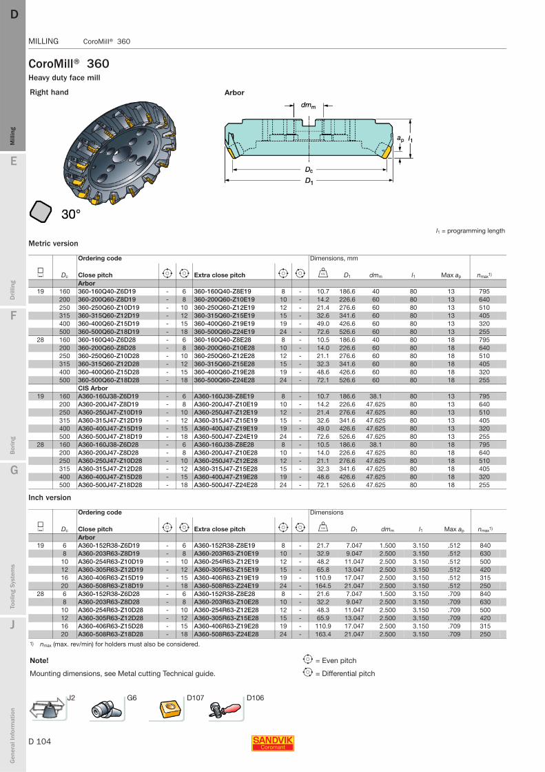
D 104
MILLING CoroMill® 360
E
Mill
ing
Drilli
ng
F
Bor
ing
G
Tool
ing
Syst
ems
J
Gen
eral
Info
rmat
ion
DDM
illin
g
MILLING CoroMill® 360
CoroMill® 360Heavy duty face mill
Metric version
Inch version
Right hand Arbor
l1 = programming length
Ordering code Dimensions, mm
J Dc Close pitch e i Extra close pitch e i U D1 dmm l1 Max ap nmax1)
Arbor19 160 360-160Q40-Z6D19 - 6 360-160Q40-Z8E19 8 - 10.7 186.6 40 80 13 795
200 360-200Q60-Z8D19 - 8 360-200Q60-Z10E19 10 - 14.2 226.6 60 80 13 640250 360-250Q60-Z10D19 - 10 360-250Q60-Z12E19 12 - 21.4 276.6 60 80 13 510315 360-315Q60-Z12D19 - 12 360-315Q60-Z15E19 15 - 32.6 341.6 60 80 13 405400 360-400Q60-Z15D19 - 15 360-400Q60-Z19E19 19 - 49.0 426.6 60 80 13 320500 360-500Q60-Z18D19 - 18 360-500Q60-Z24E19 24 - 72.6 526.6 60 80 13 255
28 160 360-160Q40-Z6D28 - 6 360-160Q40-Z8E28 8 - 10.5 186.6 40 80 18 795200 360-200Q60-Z8D28 - 8 360-200Q60-Z10E28 10 - 14.0 226.6 60 80 18 640250 360-250Q60-Z10D28 - 10 360-250Q60-Z12E28 12 - 21.1 276.6 60 80 18 510315 360-315Q60-Z12D28 - 12 360-315Q60-Z15E28 15 - 32.3 341.6 60 80 18 405400 360-400Q60-Z15D28 - 15 360-400Q60-Z19E28 19 - 48.6 426.6 60 80 18 320500 360-500Q60-Z18D28 - 18 360-500Q60-Z24E28 24 - 72.1 526.6 60 80 18 255
CIS Arbor19 160 A360-160J38-Z6D19 - 6 A360-160J38-Z8E19 8 - 10.7 186.6 38.1 80 13 795
200 A360-200J47-Z8D19 - 8 A360-200J47-Z10E19 10 - 14.2 226.6 47.625 80 13 640250 A360-250J47-Z10D19 - 10 A360-250J47-Z12E19 12 - 21.4 276.6 47.625 80 13 510315 A360-315J47-Z12D19 - 12 A360-315J47-Z15E19 15 - 32.6 341.6 47.625 80 13 405400 A360-400J47-Z15D19 - 15 A360-400J47-Z19E19 19 - 49.0 426.6 47.625 80 13 320500 A360-500J47-Z18D19 - 18 A360-500J47-Z24E19 24 - 72.6 526.6 47.625 80 13 255
28 160 A360-160J38-Z6D28 - 6 A360-160J38-Z8E28 8 - 10.5 186.6 38.1 80 18 795200 A360-200J47-Z8D28 - 8 A360-200J47-Z10E28 10 - 14.0 226.6 47.625 80 18 640250 A360-250J47-Z10D28 - 10 A360-250J47-Z12E28 12 - 21.1 276.6 47.625 80 18 510315 A360-315J47-Z12D28 - 12 A360-315J47-Z15E28 15 - 32.3 341.6 47.625 80 18 405400 A360-400J47-Z15D28 - 15 A360-400J47-Z19E28 19 - 48.6 426.6 47.625 80 18 320500 A360-500J47-Z18D28 - 18 A360-500J47-Z24E28 24 - 72.1 526.6 47.625 80 18 255
Ordering code Dimensions
J Dc Close pitch e i Extra close pitch e i V D1 dmm l1 Max ap nmax1)
Arbor19 6 A360-152R38-Z6D19 - 6 A360-152R38-Z8E19 8 - 21.7 7.047 1.500 3.150 .512 840
8 A360-203R63-Z8D19 - 8 A360-203R63-Z10E19 10 - 32.9 9.047 2.500 3.150 .512 63010 A360-254R63-Z10D19 - 10 A360-254R63-Z12E19 12 - 48.2 11.047 2.500 3.150 .512 50012 A360-305R63-Z12D19 - 12 A360-305R63-Z15E19 15 - 65.8 13.047 2.500 3.150 .512 42016 A360-406R63-Z15D19 - 15 A360-406R63-Z19E19 19 - 110.9 17.047 2.500 3.150 .512 31520 A360-508R63-Z18D19 - 18 A360-508R63-Z24E19 24 - 164.5 21.047 2.500 3.150 .512 250
28 6 A360-152R38-Z6D28 - 6 A360-152R38-Z8E28 8 - 21.6 7.047 1.500 3.150 .709 8408 A360-203R63-Z8D28 - 8 A360-203R63-Z10E28 10 - 32.2 9.047 2.500 3.150 .709 630
10 A360-254R63-Z10D28 - 10 A360-254R63-Z12E28 12 - 48.3 11.047 2.500 3.150 .709 50012 A360-305R63-Z12D28 - 12 A360-305R63-Z15E28 15 - 65.9 13.047 2.500 3.150 .709 42016 A360-406R63-Z15D28 - 15 A360-406R63-Z19E28 19 - 110.9 17.047 2.500 3.150 .709 31520 A360-508R63-Z18D28 - 18 A360-508R63-Z24E28 24 - 163.4 21.047 2.500 3.150 .709 250
1) nmax (max. rev/min) for holders must also be considered.
Note! e = Even pitch
Mounting dimensions, see Metal cutting Technical guide. i = Differential pitch
J2 G6 D107 D106

E
D 105
Mill
ing
Drilli
ng
F
Bor
ing
G
Tool
ing
Syst
ems
J
Gen
eral
Info
rmat
ion
DD
Mill
ing
CoroMill® 360 MILLING
MILLING CoroMill® 360
CoroMill® 360Heavy duty face mill
Metric version
Inch version
Left hand Arbor
l1 = programming length
Ordering code Dimensions, mm
J Dc Close pitch e i Extra close pitch e i U D1 dmm l1 Max ap nmax1)
Arbor19 160 S-360L-160Q40-Z6D19 - 6 S-360L-160Q40-Z8E19 8 - 10.7 186.6 40 80 13 795
200 S-360L-200Q60-Z8D19 - 8 S-360L-200Q60-Z10E19 10 - 14.2 226.6 60 80 13 640250 S-360L-250Q60-Z10D19 - 10 S-360L-250Q60-Z12E19 12 - 21.4 276.6 60 80 13 510315 S-360L-315Q60-Z12D19 - 12 S-360L-315Q60-Z15E19 15 - 32.6 341.6 60 80 13 405400 S-360L-400Q60-Z15D19 - 15 S-360L-400Q60-Z19E19 19 - 49.0 426.6 60 80 13 320500 S-360L-500Q60-Z18D19 - 18 S-360L-500Q60-Z24E19 24 - 72.6 526.6 60 80 13 255
28 160 S-360L-160Q40-Z6D28 - 6 S-360L-160Q40-Z8E28 8 - 10.5 186.6 40 80 18 795200 S-360L-200Q60-Z8D28 - 8 S-360L-200Q60-Z10E28 10 - 14.0 226.6 60 80 18 640250 S-360L-250Q60-Z10D28 - 10 S-360L-250Q60-Z12E28 12 - 21.1 276.6 60 80 18 510315 S-360L-315Q60-Z12D28 - 12 S-360L-315Q60-Z15E28 15 - 32.3 341.6 60 80 18 405400 S-360L-400Q60-Z15D28 - 15 S-360L-400Q60-Z19E28 19 - 48.6 426.6 60 80 18 320500 S-360L-500Q60-Z18D28 - 18 S-360L-500Q60-Z24E28 24 - 72.1 526.6 60 80 18 255
CIS Arbor19 160 S-A360L-160J38-Z6D19 - 6 S-A360L-160J38-Z8E19 8 - 10.7 186.6 38.1 80 13 795
200 S-A360L-200J47-Z8D19 - 8 S-A360L-200J47-Z10E19 10 - 14.2 226.6 47.625 80 13 640250 S-A360L-250J47-Z10D19 - 10 S-A360L-250J47-Z12E19 12 - 21.4 276.6 47.625 80 13 510315 S-A360L-315J47-Z12D19 - 12 S-A360L-315J47-Z15E19 15 - 32.6 341.6 47.625 80 13 405400 S-A360L-400J47-Z15D19 - 15 S-A360L-400J47-Z19E19 19 - 49.0 426.6 47.625 80 13 320500 S-A360L-500J47-Z18D19 - 18 S-A360L-500J47-Z24E19 24 - 72.6 526.6 47.625 80 13 255
28 160 S-A360L-160J38-Z6D28 - 6 S-A360L-160J38-Z8E28 8 - 10.5 186.6 38.1 80 18 795200 S-A360L-200J47-Z8D28 - 8 S-A360L-200J47-Z10E28 10 - 14.0 226.6 47.625 80 18 640250 S-A360L-250J47-Z10D28 - 10 S-A360L-250J47-Z12E28 12 - 21.1 276.6 47.625 80 18 510315 S-A360L-315J47-Z12D28 - 12 S-A360L-315J47-Z15E28 15 - 32.3 341.6 47.625 80 18 405400 S-A360L-400J47-Z15D28 - 15 S-A360L-400J47-Z19E28 19 - 48.6 426.6 47.625 80 18 320500 S-A360L-500J47-Z18D28 - 18 S-A360L-500J47-Z24E28 24 - 72.1 526.6 47.625 80 18 255
Ordering code Dimensions
J Dc Close pitch e i Extra close pitch e i V D1 dmm l1 Max ap nmax1)
Arbor19 6 S-A360L-152R38-Z6D19 - 6 S-A360L-152R38-Z8E19 8 - 21.7 7.047 1.500 3.150 .512 840
8 S-A360L-203R63-Z8D19 - 8 S-A360L-203R63-Z10E19 10 - 32.9 9.047 2.500 3.150 .512 63010 S-A360L-254R63-Z10D19 - 10 S-A360L-254R63-Z12E19 12 - 48.2 11.047 2.500 3.150 .512 50012 S-A360L-305R63-Z12D19 - 12 S-A360L-305R63-Z15E19 15 - 65.8 13.047 2.500 3.150 .512 42016 S-A360L-406R63-Z15D19 - 15 S-A360L-406R63-Z19E19 19 - 110.9 17.047 2.500 3.150 .512 31520 S-A360L-508R63-Z18D19 - 18 S-A360L-508R63-Z24E19 24 - 164.5 21.047 2.500 3.150 .512 250
28 6 S-A360L-152R38-Z6D28 - 6 S-A360L-152R38-Z8E28 8 - 21.6 7.047 1.500 3.150 .709 8408 S-A360L-203R63-Z8D28 - 8 S-A360L-203R63-Z10E28 10 - 32.2 9.047 2.500 3.150 .709 630
10 S-A360L-254R63-Z10D28 - 10 S-A360L-254R63-Z12E28 12 - 48.3 11.047 2.500 3.150 .709 50012 S-A360L-305R63-Z12D28 - 12 S-A360L-305R63-Z15E28 15 - 65.9 13.047 2.500 3.150 .709 42016 S-A360L-406R63-Z15D28 - 15 S-A360L-406R63-Z19E28 19 - 110.9 17.047 2.500 3.150 .709 31520 S-A360L-508R63-Z18D28 - 18 S-A360L-508R63-Z24E28 24 - 163.4 21.047 2.500 3.150 .709 250
1) nmax (max. rev/min) for holders must also be considered.
Note! e = Even pitch
Mounting dimensions, see Metal cutting Technical guide. i = Differential pitch
Left hand cutters delivered to special order. Please contact your Sandvik Coromant representative.
TO BE QUOTED
Note: Right hand cutter shown
J2 G6 D107 D106

D 106
MILLING CoroMill® 360
E
Mill
ing
Drilli
ng
F
Bor
ing
G
Tool
ing
Syst
ems
J
Gen
eral
Info
rmat
ion
DDM
illin
g
MILLING CoroMill® 360
Spare parts for CoroMill® 360
Unequipped bodiesMetric version
Inch version
1 2 3 4
Torque valueInsert size
Cassette Insert wedgeInsert wedge screw KeyRight hand Left hand Right hand Left hand Nm ft-lbs
19 360R-CA-19 360L-CA-19 360R-IW-19 360L-IW-19 267.21-830 5680 017-04(5.0) 16 11.828 360R-CA-28 360L-CA-28 360R-IW-28 360L-IW-28 267.21-830 5680 017-04(5.0) 16 11.8
5 6 7 8
Insert size Cassette wedge Cassette wedge screw Key (Torx Plus)Torque value
Torque wrench1)Nm ft-lbs19 5431 105-08 5516 010-06 5680 048-04(20IP) 6 4.4 5680 100-0728 5431 105-08 5516 010-06 5680 048-04(20IP) 6 4.4 5680 100-071) Accessories, must be ordered separately
Ordering code Dimensions, mm
Dc Close pitch e i Extra close pitch e i U D1 dmm l1Arbor
160 360-160Q40-Z6D - 6 360-160Q40-Z8E 8 - 8.9 186.6 40 80200 360-200Q60-Z8D - 8 360-200Q60-Z10E 10 - 11.2 226.6 60 80250 360-250Q60-Z10D - 10 360-250Q60-Z12E 12 - 18.4 276.6 60 80315 360-315Q60-Z12D - 12 360-315Q60-Z15E 15 - 29.0 341.6 60 80400 360-400Q60-Z15D - 15 360-400Q60-Z19E 19 - 44.5 426.6 60 80500 360-500Q60-Z18D - 18 360-500Q60-Z24E 24 - 67.2 526.6 60 80
CIS Arbor160 A360-160J38-Z6D - 6 A360-160J38-Z8E 8 - 8.9 186.6 38.1 80200 A360-200J47-Z8D - 8 A360-200J47-Z10E 10 - 11.2 226.6 47.625 80250 A360-250J47-Z10D - 10 A360-250J47-Z12E 12 - 18.4 276.6 47.625 80315 A360-315J47-Z12D - 12 A360-315J47-Z15E 15 - 29.0 341.6 47.625 80400 A360-400J47-Z15D - 15 A360-400J47-Z19E 19 - 44.5 426.6 47.625 80500 A360-500J47-Z18D - 18 A360-500J47-Z24E 24 - 67.2 526.6 47.625 80
Ordering code Dimensions, mm
Dc Close pitch e i Extra close pitch e i U D1 dmm l1Arbor
6 A360-152R38-Z6D - 6 A360-152R38-Z8E 8 - 17.6 7.346 1.500 3.1508 A360-203R63-Z8D - 8 A360-203R63-Z10E 10 - 25.6 8.921 2.500 3.15010 A360-254R63-Z10D - 10 A360-254R63-Z12E 12 - 41.7 10.890 2.500 3.15012 A360-305R63-Z12D - 12 A360-305R63-Z15E 15 - 58.0 13.449 2.500 3.15016 A360-406R63-Z15D - 15 A360-406R63-Z19E 18 - 101.0 16.795 2.500 3.15020 A360-508R63-Z18D - 18 A360-508R63-Z24E 24 152.6 20.732 2.500 3.150
Left hand cutters delivered to special order. Please contact your Sandvik Coromant representative.

E
D 107
Mill
ing
Drilli
ng
F
Bor
ing
G
Tool
ing
Syst
ems
J
Gen
eral
Info
rmat
ion
DD
Mill
ing
CoroMill® 360 MILLING
MILLING CoroMill® 360
Inserts for CoroMill® 360
Cutting data
Cemented carbide
Heavy
Right hand style shown
Dimensions, mm (inch)Size l = iC la s 19 19 (.748) 15 (.591) 6.35 (.250)28 28 (1.102) 20 (.787) 7.94 (.313)
P M K S Dimensions, millimeter, inch (mm, in.)
iC Ordering codeMax ap
mmMax ap
inch
GC GC GC GC GC GC GC GC GC GC
bsmm
bsin.42
2042
3042
4020
3020
4030
4032
2042
2020
3020
40
Hea
vy
19 360L-1906M-KH 13.0 .512 ★ 2.2 .087360L-1906M-MH 13.0 .512 ★ ✩ 2.2 .087360L-1906M-PH 13.0 .512 ★ 2.2 .087360R-19 06M-KH 13.0 .512 ★ ★ 2.2 .087360R-19 06M-MH 13.0 .512 ★ ★ ✩ ✩ 2.2 .087360R-19 06M-PH 13.0 .512 ★ ★ ★ ✩ 2.2 .087
Hea
vy
28 360L-2807M-KH 18.0 .709 ★ 4.6 .181360L-2807M-MH 18.0 .709 ★ ✩ 4.6 .181360L-2807M-PH 18.0 .709 ★ 4.6 .181360R-28 07M-KH 18.0 .709 ★ ★ 4.6 .181360R-28 07M-MH 18.0 .709 ★ ★ ✩ ✩ 4.6 .181360R-28 07M-PH 18.0 .709 ★ ★ ★ ✩ 4.6 .181
P15
P25
P40
M25
M30
K30
K20
K25
S25
S30
★= First choice
Feed per tooth, fz mm (inch)
mm/tooth (inch/tooth) Cutting speed vc Cutting speed vc Cutting speed vc
GC4220 GC4230 GC4240m/min ft/min m/min ft/min m/min ft/min
P 0.46 (.018) 0.30-0.69 (.012-.027) 186 610 151 495 130 425(125-227) (410-745) (102-184) (335-605) (87-157) (285-515)
GC2030 GC2040M 0.46 (.018) 0.30-0.69 (.012-.027) 117 385 113 370
(75-148) (245-485) (72-140) (235-460)
GC3220 GC3240K 0.46 (.018) 0.30-0.69 (.012-.027) 142 465 111 365
(96-174) (315-570) (75-136) (245-445)
D312 D305

D 108
MILLING CoroMill® 300
E
Mill
ing
Drilli
ng
F
Bor
ing
G
Tool
ing
Syst
ems
J
Gen
eral
Info
rmat
ion
DDM
illin
g
MILLING CoroMill® 300
CoroMill® 300 Light cutting face and profile milling cutters
Versatile concept for roughing to high feed semi-finishing
Geometries:
Roughing
ISO application areas:
High feed semi-finishing
Extra close pitch version
Pitch: L M H
Condition: Unstable
Light cutting First choice semi-finishing
First choice roughing
Stable
Tool options designed to individual customer requirements are available. For information on our Tailor Made programme see page J3.
General
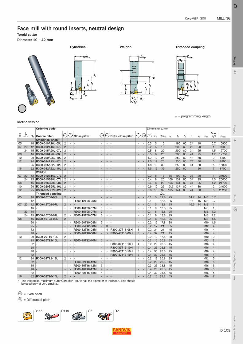
E
D 109
Mill
ing
Drilli
ng
F
Bor
ing
G
Tool
ing
Syst
ems
J
Gen
eral
Info
rmat
ion
DD
Mill
ing
CoroMill® 300 MILLING
MILLING CoroMill® 300
Face mill with round inserts, neutral designToroid cutterDiameter 10 – 42 mm
Metric version
Cylindrical Weldon Threaded coupling
l1 = programming length
Ordering code Dimensions, mm
L T D3 Coarse pitch e i Close pitch e i Extra close pitch e i U Dc dmm l1 l2 l3 l4 l5 dth
Max ap1) nmax
Cylindrical shank05 10 R300-010A16L-05L 2 - - - - - - - 0.3 5 16 160 60 24 18 0.7 1590007 20 12 R300-012A16L-07L 2 - - - - - - - 0.2 5 16 200 60 28 20 1 8900
24 15 R300-015A20L-07L 2 - - - - - - - 0.5 8 20 200 80 34 25 1.5 1270008 16 R300-016A20L-08L 2 - - - - - - - 0.5 8 20 200 80 44 25 1.2 1270010 20 R300-020A25L-10L 2 - - - - - - - 1.2 10 25 250 80 44 30 2 810012 24 R300-024A25L-12L 2 - - - - - - - 1.0 12 25 250 80 74 30 5 8900
25 R300-025A32L-12L 2 - - - - - - - 1.8 13 32 250 80 41 30 5 1580016 32 R300-032A32L-16L 2 - - - - - - - 1.5 16 32 250 80 30 7 8700
Weldon07 20 12 R300-012B16L-07L 2 - - - - - - - 0.2 5 16 85 109 60 28 20 1 34000
24 15 R300-015B20L-07L 2 - - - - - - - 0.4 8 20 106 131 80 34 25 1.5 2500008 16 R300-016B20L-08L 2 - - - - - - - 0.4 8 20 106 131 80 44 25 1.2 2470010 20 R300-020B25L-10L 2 - - - - - - - 0.6 10 25 104.5 137 80 44 30 2 3400012 25 R300-025B32L-12L 2 - - - - - - - 0.8 13 32 105 141 80 44 30 5 20200
Threaded coupling D5m
05 10 R300-10T08-05L 2 - - - - - - - 0.1 5 12.8 25 14.7 14 M8 0.712 - - - R300-12T08-05M 3 - - - - 0.1 12.8 25 17 15 M8 0.7
07 20 12 R300-12T08-07L 2 - - - - - - - 0.1 5 12.8 25 16.6 14 M8 116 - - - R300-16T08-07M 3 - - - - 0.1 9 12.8 25 M8 1
20 15 - - - R300-15T08-07M 3 - - - - 0.1 8 12.8 25 M8 1.224 15 R300-15T08-07L 2 - R300-15T08-07M 3 - - - - 0.1 8 12.8 25 M8 1.2
08 16 R300-16T08-08L 2 - - - - - - - 0.1 8 12.8 25 M8 1.520 - - - R300-20T10-08M 3 - - - - 0.2 12 17.8 30 M10 1.525 - - - R300-25T12-08M - 3 - - - 0.2 17 21 35 M12 432 - - - R300-32T16-08M - 4 R300-32T16-08H 5 - 0.2 24 21 45 M16 440 - - - R300-40T16-08M - 5 R300-40T16-08H 6 - 0.4 32 21 45 M16 4
10 20 R300-20T10-10L 2 - - - - - - - 0.2 10 17.8 30 M10 225 R300-25T12-10L 2 - R300-25T12-10M 3 - - - - 0.2 15 20.8 35 M12 232 - - - - - - R300-32T16-10H 4 - 0.2 22 28.8 45 M16 435 - - - - - - R300-35T16-10H 4 - 0.4 25 28.8 45 M16 440 - - - - - - R300-40T16-10H 5 - 0.4 30 28.8 45 M16 442 - - - - - - R300-42T16-10H 5 - 0.4 32 28.8 45 M16 4
12 24 R300-24T12-12L 2 - - - - - - - 0.2 12 20.8 35 M12 532 - - - R300-32T16-12M 3 - - - - 0.2 20 28.8 45 M16 535 - - - R300-35T16-12M 3 - - - - 0.3 23 28.8 45 M16 540 - - - R300-40T16-12M 4 - - - - 0.4 28 28.8 45 M16 542 - - - R300-42T16-12M 4 - - - - 0.4 30 28.8 45 M16 5
16 32 R300-32T16-16L 2 - - - - - - - 0.2 16 28.8 45 M16 71) The theoretical maximum ap for CoroMill® 300 is half the diameter of the insert. This should
be used only at very small ae.
e = Even pitch
i = Differential pitch
D115 D119 G6 D2
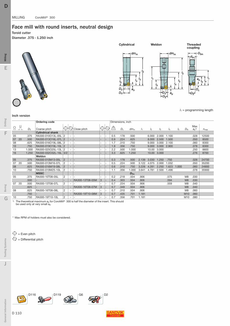
D 110
MILLING CoroMill® 300
E
Mill
ing
Drilli
ng
F
Bor
ing
G
Tool
ing
Syst
ems
J
Gen
eral
Info
rmat
ion
DDM
illin
g
MILLING CoroMill® 300
Face mill with round inserts, neutral designToroid cutterDiameter .375 - 1.250 inch
Inch version
Cylindrical Weldon Threaded coupling
l1 = programming length
Ordering code Dimensions, inch
L T D3 Coarse pitch e i Close pitch e i V Dc dmm l1 l2 l3 l4 l5 Dth
Max ap1) nmax
Cylindrical shank05 .375 RA300-010O13L-05L 2 - - - - 0.5 .178 .500 6.000 2.000 1.100 .028 1250007 20 .500 RA300-013O16L-07L 2 - - - - 0.9 .224 .625 8.000 2.500 1.500 .050 850008 .625 RA300-016O19L-08L 2 - - - - 1.7 .310 .750 9.000 3.000 2.100 .060 830010 .750 RA300-019O19L-10L 2 - - - - 1.9 .356 .750 9.000 3.000 2.900 .078 830013 1.000 RA300-025O25L-13L 2 - - - - 2.2 .500 1.000 10.00 3.000 .250 880016 1.250 RA300-032O32L-16L 3/2 - - - - 3.3 .625 1.250 10.00 3.000 .276 8700
Weldon05 .375 RA300-010M13-05L 2 - - - - 0.3 .178 .500 2.139 3.030 1.250 .750 .028 2470007 20 .500 RA300-013M16-07L 2 - - - - 0.5 .224 .500 3.122 4.075 2.000 1.032 .050 3520008 .625 RA300-016M19-08L 2 - - - - 0.6 .310 .750 3.226 4.281 2.250 1.623 1.000 .060 2490010 .750 RA300-019M25-10L 2 - - - - 1.1 .356 1.000 3.641 4.781 2.500 1.496 .078 35900
MSSC D5m
05 .375 RA300-10T08-05L 2 - - - - 0.2 .218 .504 .906 .575 M8 .030.500 - - - RA300-13T08-05M 3 - 0.4 .303 .504 .906 .594 M8 .030
07 20 .500 RA300-13T08-07L 2 - - - - 0.7 .224 .504 .906 .559 M8 .040.625 - - - RA300-16T08-07M 3 - 0.7 .349 .504 .906 M8 .040
08 .625 RA300-16T08-08L 2 - - - - 0.7 .310 .504 .906 M8 .060.750 - - - RA300-19T10-08M 3 - 0.7 .435 .701 1.181 M10 .060
10 .750 RA300-19T10-10L 2 - - - - 0.7 .356 .701 1.181 M10 .0801) The theoretical maximum ap for CoroMill® 300 is half the diameter of the insert. This should
be used only at very small ae.
* Max RPM of holders must also be considered.
e = Even pitch
i = Differential pitch
D116 D119 G6 D2
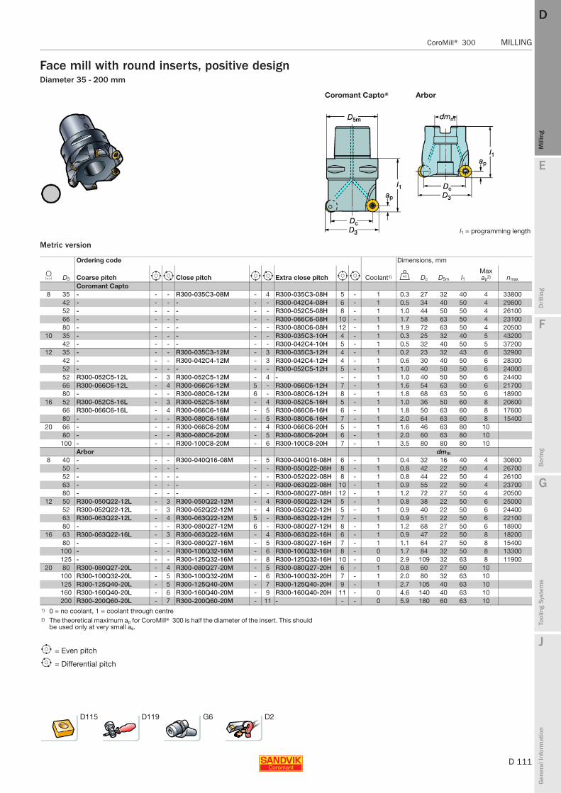
E
D 111
Mill
ing
Drilli
ng
F
Bor
ing
G
Tool
ing
Syst
ems
J
Gen
eral
Info
rmat
ion
DD
Mill
ing
CoroMill® 300 MILLING
MILLING CoroMill® 300
Face mill with round inserts, positive designDiameter 35 - 200 mm
Metric version
Coromant Capto® Arbor
l1 = programming length
Ordering code Dimensions, mm
L D3 Coarse pitch e i Close pitch e i Extra close pitch e i Coolant1) U Dc D5m l1Max ap2) nmax
Coromant Capto 8 35 - - - R300-035C3-08M - 4 R300-035C3-08H 5 - 1 0.3 27 32 40 4 33800
42 - - - - - - R300-042C4-08H 6 - 1 0.5 34 40 50 4 2980052 - - - - - - R300-052C5-08H 8 - 1 1.0 44 50 50 4 2610066 - - - - - - R300-066C6-08H 10 - 1 1.7 58 63 50 4 2310080 - - - - - - R300-080C6-08H 12 - 1 1.9 72 63 50 4 20500
10 35 - - - - - - R300-035C3-10H 4 - 1 0.3 25 32 40 5 4320042 - - - - - - R300-042C4-10H 5 - 1 0.5 32 40 50 5 37200
12 35 - - - R300-035C3-12M - 3 R300-035C3-12H 4 - 1 0.2 23 32 43 6 3290042 - - - R300-042C4-12M - 3 R300-042C4-12H 4 - 1 0.6 30 40 50 6 2830052 - - - - - - R300-052C5-12H 5 - 1 1.0 40 50 50 6 2400052 R300-052C5-12L - 3 R300-052C5-12M - 4 - - - 1 1.0 40 50 50 6 2440066 R300-066C6-12L - 4 R300-066C6-12M 5 - R300-066C6-12H 7 - 1 1.6 54 63 50 6 2170080 - - - R300-080C6-12M 6 - R300-080C6-12H 8 - 1 1.8 68 63 50 6 18900
16 52 R300-052C5-16L - 3 R300-052C5-16M - 4 R300-052C5-16H 5 - 1 1.0 36 50 60 8 2060066 R300-066C6-16L - 4 R300-066C6-16M - 5 R300-066C6-16H 6 - 1 1.8 50 63 60 8 1760080 - - - R300-080C6-16M - 5 R300-080C6-16H 7 - 1 2.0 64 63 60 8 15400
20 66 - - - R300-066C6-20M - 4 R300-066C6-20H 5 - 1 1.6 46 63 80 1080 - - - R300-080C6-20M - 5 R300-080C6-20H 6 - 1 2.0 60 63 80 10
100 - - - R300-100C8-20M - 6 R300-100C8-20H 7 - 1 3.5 80 80 80 10Arbor dmm
8 40 - - - R300-040Q16-08M - 5 R300-040Q16-08H 6 - 1 0.4 32 16 40 4 3080050 - - - - - - R300-050Q22-08H 8 - 1 0.8 42 22 50 4 2670052 - - - - - - R300-052Q22-08H 8 - 1 0.8 44 22 50 4 2610063 - - - - - - R300-063Q22-08H 10 - 1 0.9 55 22 50 4 2370080 - - - - - - R300-080Q27-08H 12 - 1 1.2 72 27 50 4 20500
12 50 R300-050Q22-12L - 3 R300-050Q22-12M - 4 R300-050Q22-12H 5 - 1 0.8 38 22 50 6 2500052 R300-052Q22-12L - 3 R300-052Q22-12M - 4 R300-052Q22-12H 5 - 1 0.9 40 22 50 6 2440063 R300-063Q22-12L - 4 R300-063Q22-12M 5 - R300-063Q22-12H 7 - 1 0.9 51 22 50 6 2210080 - - - R300-080Q27-12M 6 - R300-080Q27-12H 8 - 1 1.2 68 27 50 6 18900
16 63 R300-063Q22-16L - 3 R300-063Q22-16M - 4 R300-063Q22-16H 6 - 1 0.9 47 22 50 8 1820080 - - - R300-080Q27-16M - 5 R300-080Q27-16H 7 - 1 1.1 64 27 50 8 15400
100 - - - R300-100Q32-16M - 6 R300-100Q32-16H 8 - 0 1.7 84 32 50 8 13300125 - - - R300-125Q32-16M - 8 R300-125Q32-16H 10 - 0 2.9 109 32 63 8 11900
20 80 R300-080Q27-20L - 4 R300-080Q27-20M - 5 R300-080Q27-20H 6 - 1 0.8 60 27 50 10100 R300-100Q32-20L - 5 R300-100Q32-20M - 6 R300-100Q32-20H 7 - 1 2.0 80 32 63 10125 R300-125Q40-20L - 5 R300-125Q40-20M - 7 R300-125Q40-20H 9 - 1 2.7 105 40 63 10160 R300-160Q40-20L - 6 R300-160Q40-20M - 9 R300-160Q40-20H 11 - 0 4.6 140 40 63 10200 R300-200Q60-20L - 7 R300-200Q60-20M - 11 - - - 0 5.9 180 60 63 10
1) 0 = no coolant, 1 = coolant through centre2) The theoretical maximum ap for CoroMill® 300 is half the diameter of the insert. This should
be used only at very small ae.
e = Even pitch
i = Differential pitch
D115 D119 G6 D2

D 112
MILLING CoroMill® 300
E
Mill
ing
Drilli
ng
F
Bor
ing
G
Tool
ing
Syst
ems
J
Gen
eral
Info
rmat
ion
DDM
illin
g
MILLING CoroMill® 300
Face mill with round inserts, positive designDiameter 25 - 40 mm
Metric version
Cylindrical Threaded coupling
l1 = programming length
Ordering code Dimensions, mm
L D3 Coarse pitch e i Close pitch e i Extra close pitch e i Coolant1) U Dc
D5m
dmm l1 l2 l3 Dth
Max ap nmax
Cylindrical shank08 25 - - - R300-025A20-08M - 3 - - - 1 0. 17 20 150 40 4 7200
32 - - - - - - R300-032A25-08H 5 - 1 0. 24 25 150 40 4 359032 - - - R300-032A25-08M - 4 - - - 1 0. 24 25 190 40 4 9000
10 25 - - - R300-025A20-10M - 2 - - - 1 0. 15 20 150 40 5 285032 - - - - - - R300-032A25-10H 4 - 1 0. 22 25 150 40 5 285032 - - - R300-032A25-10M - 3 - - - 1 0. 22 25 190 40 5 1470
12 32 - - - - - - R300-032A25-12H 3 - 1 0. 20 25 150 40 6 355032 - - - R300-032A25-12M 2 - - - - 1 1. 20 25 190 40 6 890040 - - - - - - R300-040A32-12H 4 - 1 1. 28 32 150 40 6 285040 - - - R300-040A32-12M - 3 - - - 1 1. 28 32 250 40 6 1140
MSSC08 25 - - - R300-25T12-08M - 3 - - - 1 0. 17 21 35 M12 4
32 - - - R300-32T16-08M - 4 R300-32T16-08H 5 - 1 0. 24 21 45 M16 440 - - - R300-40T16-08M - 5 R300-40T16-08H 6 - 1 0. 32 21 45 M16 4
1) 0 = no coolant, 1 = coolant through centre
e = Even pitch
i = Differential pitch
D115 D119 G6 D2

E
D 113
Mill
ing
Drilli
ng
F
Bor
ing
G
Tool
ing
Syst
ems
J
Gen
eral
Info
rmat
ion
DD
Mill
ing
CoroMill® 300 MILLING
MILLING CoroMill® 300
Face mill with round inserts, positive designDiameter 1.000 - 8.000 inch
Inch version
Coromant Capto® Arbor
Ordering code Dimensions, inch
L D3 Coarse pitch e i Close pitch e i Extra close pitch e i Coolant1) V Dc D5m dmm l1Max ap2) nmax
Coromant Capto 13 2.000 - - - - - - RA300-052C5-13H 5 - 1 1.8 1.547 1.968 1.968 .248 16900
2.000 RA300-052C5-13L - 3 RA300-052C5-13M - 4 - - - 1 1.8 1.547 1.968 2.000 .248 166002.600 RA300-066C6-13L - 4 RA300-066C6-13M - 5 RA300-066C6-13H 7 - 1 2.6 1.980 2.480 2.000 .248 14300
16 3.000 RA300-076C6-16L 4 - RA300-076C6-16M 5 - RA300-076C6-16H - 7 1 4.3 2.362 2.480 2.362 .315 1600020 3.000 - - - RA300-076C6-20M - 4 RA300-076C6-20H 5 - 1 4.3 2.228 2.480 3.150 .394
4.000 - - - RA300-102C8-20M - 6 RA300-102C8-20H 7 - 1 7.7 3.213 3.150 3.150 .39425 3.000 RA300-076C6-25L - 3 RA300-076C6-25M - 4 - - - 1 4.3 2.016 2.480 3.150 .492
4.000 - - - RA300-102C8-25M - 4 RA300-102C8-25H 6 - 1 7.7 3.000 3.150 3.150 .492Arbor
13 2.000 - - - RA300-051R19-13M - 4 RA300-051R19-13H 5 - 1 1.5 1.508 .750 1.968 .248 169002.000 RA300-051R19-13L - 3 - - - - - - 1 1.5 1.508 .750 1.968 .248 169002.500 RA300-063R19-13L - 4 RA300-063R19-13M - 5 RA300-063R19-13H 6 - 1 1.1 1.980 .750 1.968 .248 147003.000 RA300-076R25-13L - 5 RA300-076R25-13M - 6 RA300-076R25-13H 7 - 1 3.3 2.492 1.000 1.968 .248 13500
16 2.500 RA300-063R19-16L - 3 RA300-063R19-16M - 4 RA300-063R19-16H 6 - 1 1.0 1.850 .750 1.968 .315 182003.000 - - - RA300-076R25-16M - 5 RA300-076R25-16H 7 - 1 2.6 2.362 1.000 1.968 .315 160004.000 RA300-102R38-16L - 5 RA300-102R38-16M - 6 RA300-102R38-16H 8 - 0 4.9 3.386 1.500 2.480 .315 13200
20 3.000 RA300-076R25-20L - 3 RA300-076R25-20M - 4 RA300-076R25-20H 5 - 1 1.8 2.228 1.000 2.480 .3944.000 RA300-102R38-20L - 5 RA300-102R38-20M - 6 RA300-102R38-20H 7 - 1 4.4 3.213 1.500 2.480 .4925.000 RA300-127R38-20L - 5 RA300-127R38-20M - 7 - - - 1 6.4 4.213 1.500 2.480 .3946.000 RA300-152R38-20L - 7 RA300-152R38-20M - 9 RA300-152R38-20H 10 - 0 9.0 5.213 1.500 2.480 .3948.000 RA300-203R63-20L - 7 RA300-203R63-20M - 11 - - - 0 13.2 7.213 2.500 2.480 .394
25 3.000 RA300-076R25-25L - 3 RA300-076R25-25M - 4 - - - 1 1.8 2.228 1.000 2.480 .3944.000 - - - RA300-102R38-25M - 4 RA300-102R38-25H 6 - 1 4.4 3.213 1.500 2.480 .3945.000 RA300-127R38-25L - 4 RA300-127R38-25M - 5 RA300-127R38-25H 7 - 1 6.4 4.213 1.500 2.480 .3946.000 RA300-152R38-25L - 5 RA300-152R38-25M - 7 RA300-152R38-25H 8 - 0 9.0 5.213 1.500 2.480 .3948.000 RA300-203R63-25L - 6 RA300-203R63-25M - 8 RA300-203R63-25H 11 - 0 13.2 7.213 2.500 2.480 .394
1) 0 = no coolant, 1 = coolant through centre2) The theoretical maximum ap for CoroMill® 300 is half the diameter of the insert. This should
be used only at very small ae.
Note!Coolant screws are ordered separately
e = Even pitch
i = Differential pitch
D116 D119 G6 D2

D 114
MILLING CoroMill® 300
E
Mill
ing
Drilli
ng
F
Bor
ing
G
Tool
ing
Syst
ems
J
Gen
eral
Info
rmat
ion
DDM
illin
g
MILLING CoroMill® 300
Face mill with round inserts, positive designDiameter .375 - 1.500 inch
Inch version
Cylindrical Weldon
l1 = programming length
Ordering code Dimensions, inch
L D3 Coarse pitch e Close pitch i Extra close pitch e i Coolant1) V Dc dmm l1 l2 l3Max ap2) nmax
Cylindrical shank05 .375 RA300-010O13L-05L 2 - - - - - 0 0.5 .178 .500 6.000 2.000 .028 1250007 .500 RA300-013O16L-07L 2 - - - - - 0 0.9 .224 .625 8.000 2.500 .050 850008 .625 RA300-016O19L-08L 2 - - - - - 0 1.7 .310 .750 9.000 3.000 .060 830009 1.000 - - - - RA300-025O25-09H 3 - 1 1.5 .625 1.000 6.000 1.400 .177 27400
1.000 - - RA300-025O25-09M 2 - - - 1 2.0 .625 1.000 7.500 1.500 .177 145001.250 - - - - RA300-032O32-09H 4 - 1 1.5 .905 1.250 6.000 1.400 .177 274001.250 - - RA300-032O32-09M 3 - - - 1 1.5 .905 1.250 10.000 1.400 .177 74001.500 - - - - RA300-038O32-09H 4 - 1 2.4 1.142 1.250 6.000 1.400 .177 27400
10 .750 RA300-019O19L-10L 2 - - - - - 0 1.9 .356 .750 9.000 3.000 .078 830013 1.000 RA300-025O25L-13L 2 - - - - - 1 2.2 .500 1.000 10.000 3.000 .250 8800
1.250 - - - - RA300-032O32-13H 3 - 1 1.5 .750 1.250 6.000 1.500 .248 251001.250 - - RA300-032O32-13M 2 - - - 1 1.5 .750 1.250 10.000 1.500 .248 74001.500 - - - - RA300-038O32-13H 4 - 1 2.4 1.000 1.250 6.000 1.500 .248 216001.500 - - RA300-038O32-13M 3 - - - 1 3.3 1.000 1.250 10.000 1.500 .248 7400
16 1.250 RA300-032O32L-16L 3/2 - - - - - 1 3.3 .625 1.250 10.000 3.000 .276 8700Weldon
05 .375 RA300-010M13-05L 2 - - - - - 0 0.3 .178 .500 2.139 3.030 1.250 .028 2470007 .500 RA300-013M16-07L 2 - - - - - 0 0.5 .224 .500 3.122 4.075 2.000 .050 3520008 .625 RA300-016M19-08L 2 - - - - - 0 0.6 .310 .750 3.226 4.281 2.250 .060 2490009 1.000 - - - - RA300-025M25-09H 3 - 0 1.5 .625 1.000 4.142 5.284 2.685 .177 27400
1.000 - - RA300-025M25-09M 2 - - - 0 1.5 .625 1.000 4.142 5.284 2.685 .177 145001.250 - - - - RA300-032M32-09H 4 - 1 1.5 .905 1.250 4.807 5.949 3.354 .177 274001.250 - - RA300-032M32-09M 3 - - - 1 3.5 .905 1.250 4.807 5.949 3.354 .177 74001.500 - - - - RA300-038M32-09H - 4 1 2.0 1.142 1.250 5.141 6.284 4.000 .177 27400
10 .750 RA300-019M25-10L 2 - - - - - 0 1.1 .356 1.000 3.641 4.781 2.500 .078 3590013 1.250 - - RA300-032M32-13M 2 RA300-032M32-13H 3 - 1 1.5 .750 1.250 4.807 5.949 3.354 .248 25100
1.500 - - RA300-038M32-13M 3 RA300-038M32-13H 4 - 1 2.0 1.000 1.250 5.142 6.284 3.685 .248 216001) 0 = no coolant, 1 = coolant through centre2) The theoretical maximum ap for CoroMill® 300 is half the diameter of the insert. This should
be used only at very small ae.
Note!Coolant screws are ordered separately
e = Even pitch
i = Differential pitch
D116 D119 G6 D2
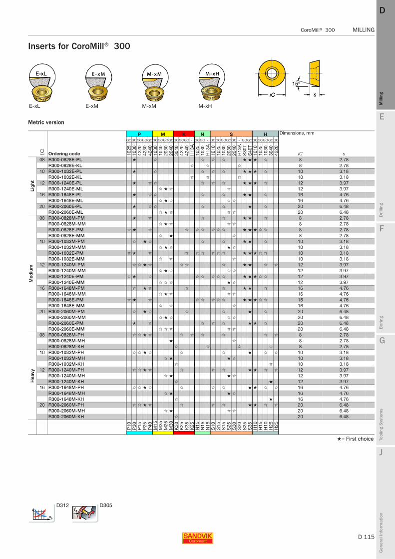
E
D 115
Mill
ing
Drilli
ng
F
Bor
ing
G
Tool
ing
Syst
ems
J
Gen
eral
Info
rmat
ion
DD
Mill
ing
CoroMill® 300 MILLING
MILLING CoroMill® 300
Inserts for CoroMill® 300
Metric version
E-xL E-xM M-xM M-xH
P M K N S H Dimensions, mm
L Ordering code
GCGCGCGCGCGCGCGCGCGCGCGC - GCGC - GCGCGCGCGC - GCGCGCGCGCGCGC
iC s 1025
1030
4220
4230
4240
1030
1040
2030
2040
3040
4220
4240
H13
A10
2510
30H
13A
1010
1025
1030
2030
2040
H13
AS
30T
S40
T10
1010
2510
3030
4042
20
Lig
ht
08 R300-0828E-PL ★ ✩ ✩ ✩ ✩ ★ ★ ★ ✩ 8 2.78R300-0828E-KL ✩ ✩ ✩ 8 2.78
10 R300-1032E-PL ★ ✩ ✩ ✩ ✩ ★ ★ ★ ✩ 10 3.18R300-1032E-KL ✩ ✩ ✩ 10 3.18
12 R300-1240E-PL ★ ✩ ✩ ✩ ✩ ✩ ★ ★ ★ ✩ 12 3.97R300-1240E-ML ✩ ★ ✩ ✩ 12 3.97
16 R300-1648E-PL ★ ✩ ✩ ✩ ✩ ★ ★ ✩ 16 4.76R300-1648E-ML ✩ ★ ✩ ✩ ✩ 16 4.76
20 R300-2060E-PL ★ ✩ ✩ ✩ ✩ ★ ✩ 20 6.48R300-2060E-ML ✩ ★ ✩ ✩ ✩ 20 6.48
Med
ium
08 R300-0828M-PM ★ ✩ ✩ ✩ ★ ★ ✩ 8 2.78R300-0828M-MM ✩ ★ ✩ ✩ ✩ 8 2.78R300-0828E-PM ✩ ★ ✩ ✩ ✩ ✩ ✩ ✩ ✩ ★ ★ ★ ✩ ✩ 8 2.78R300-0828E-MM ✩ ★ ✩ 8 2.78
10 R300-1032M-PM ✩ ★ ✩ ✩ ✩ ★ ★ ✩ 10 3.18R300-1032M-MM ✩ ★ ✩ ★ ✩ 10 3.18R300-1032E-PM ✩ ★ ✩ ✩ ✩ ✩ ✩ ✩ ✩ ★ ★ ★ ✩ ✩ 10 3.18R300-1032E-MM ✩ ✩ ✩ 10 3.18
12 R300-1240M-PM ✩ ✩ ★ ✩ ✩ ✩ ✩ ★ ★ ✩ ✩ 12 3.97R300-1240M-MM ✩ ★ ✩ ✩ ✩ 12 3.97R300-1240E-PM ✩ ★ ✩ ✩ ✩ ✩ ✩ ✩ ★ ★ ★ ✩ ✩ 12 3.97R300-1240E-MM ✩ ✩ ✩ ★ ✩ 12 3.97
16 R300-1648M-PM ✩ ★ ✩ ✩ ✩ ★ ★ ✩ 16 4.76R300-1648M-MM ✩ ★ ✩ ✩ ✩ 16 4.76R300-1648E-PM ✩ ★ ✩ ✩ ✩ ✩ ✩ ✩ ★ ★ ★ ✩ ✩ 16 4.76R300-1648E-MM ✩ ✩ ✩ 16 4.76
20 R300-2060M-PM ✩ ★ ✩ ✩ ✩ ★ ✩ 20 6.48R300-2060M-MM ✩ ★ ✩ ✩ ✩ 20 6.48R300-2060E-PM ★ ✩ ✩ ✩ ✩ ★ ★ ✩ 20 6.48R300-2060E-MM ✩ ✩ ✩ ✩ ✩ 20 6.48
Hea
vy
08 R300-0828M-PH ✩ ✩ ★ ✩ ✩ ✩ ✩ ✩ ✩ ✩ 8 2.78R300-0828M-MH ★ ✩ 8 2.78R300-0828M-KH ✩ ✩ ✩ ✩ 8 2.78
10 R300-1032M-PH ✩ ✩ ★ ✩ ✩ ✩ ★ ✩ ✩ 10 3.18R300-1032M-MH ✩ ★ ★ ✩ 10 3.18R300-1032M-KH ✩ ✩ 10 3.18
12 R300-1240M-PH ✩ ✩ ★ ✩ ✩ ✩ ✩ ★ ★ ✩ ✩ 12 3.97R300-1240M-MH ✩ ★ ★ ✩ 12 3.97R300-1240M-KH ✩ ★ 12 3.97
16 R300-1648M-PH ✩ ✩ ★ ✩ ✩ ✩ ✩ ★ ★ ✩ ✩ 16 4.76R300-1648M-MH ✩ ★ ★ ✩ 16 4.76R300-1648M-KH ✩ ★ 16 4.76
20 R300-2060M-PH ✩ ✩ ★ ✩ ✩ ✩ ✩ ★ ★ ✩ ✩ 20 6.48R300-2060M-MH ✩ ★ ✩ ✩ 20 6.48R300-2060M-KH ✩ 20 6.48
P10
P30
P15
P25
P40
M15
M35
M25
M30
K30
K25
K35
K25
N15
N15
N15
S10
S15
S15
S25
S30
S20
S25
S35
H10
H15
H10
H25
H25
★= First choice
D312 D305
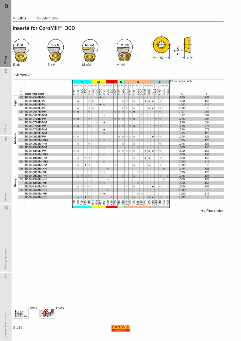
D 116
MILLING CoroMill® 300
E
Mill
ing
Drilli
ng
F
Bor
ing
G
Tool
ing
Syst
ems
J
Gen
eral
Info
rmat
ion
DDM
illin
g
MILLING CoroMill® 300
Inserts for CoroMill® 300
Inch version
E-xL E-xM M-xM M-xH
P M K N S H Dimensions, inch
L Ordering code
GC GC GC GC GC GC GC GC GC GC GC GC GC GC GC GC GC GC GC GC GC GC GC GC GC GC
iC s 1025
1030
4220
4230
4240
1030
1040
2030
2040
3040
4220
4240
1025
1030
1010
1025
1030
2030
2040
S30
TS
40T
1010
1025
1030
3040
4220
Lig
ht
13 R300-1340E-ML ✩ ★ ✩ ✩ ✩ .500 .156R300-1340E-PL ★ ✩ ✩ ✩ ✩ ✩ ★ ★ ★ ✩ .500 .156
25 R300-2570E-ML ✩ ★ ✩ ✩ ✩ 1.000 .313R300-2570E-PL ★ ✩ ✩ ✩ ✩ ✩ ★ ★ ✩ 1.000 .313
Med
ium
05 R300-0517E-PM ✩ ★ ✩ ✩ ✩ ✩ ✩ ★ ✩ ✩ .197 .067R300-0517E-MM ✩ ✩ .197 .067
07 R300-0724E-PM ✩ ★ ✩ ✩ ✩ ✩ ✩ ★ ✩ ✩ .276 .094R300-0724E-MM ✩ ★ ✩ .276 .094R300-0720E-PM ✩ ★ ✩ ✩ ✩ ✩ ✩ ★ ✩ ✩ .276 .078R300-0720E-MM ✩ ★ ✩ .276 .078
09 R300-0932E-MM ✩ ✩ .375 .125R300-0932E-PM ✩ ✩ ✩ ✩ ✩ ✩ ✩ ★ ✩ ✩ .375 .125R300-0932M-MM ✩ ✩ ✩ ✩ .375 .125R300-0932M-PM ✩ ✩ ✩ ✩ ✩ .375 .125
13 R300-1340E-MM ✩ ✩ ✩ ✩ ✩ .500 .156R300-1340E-PM ✩ ✩ ✩ ✩ ✩ ✩ ✩ ★ ★ ★ ✩ ✩ .500 .156R300-1340M-MM ✩ ✩ ✩ ✩ ✩ .500 .156R300-1340M-PM ✩ ✩ ✩ ✩ ★ ★ ✩ .500 .156
25 R300-2570M-MM ✩ ✩ ✩ 1.000 .313R300-2570M-PM ✩ ★ ✩ ✩ ✩ ★ ✩ 1.000 .313
Hea
vy
09 R300-0932M-KH ✩ ✩ .375 .125R300-0932M-MH ✩ ✩ ✩ ✩ .375 .125R300-0932M-PH ✩ ✩ ✩ ✩ ✩ ✩ ✩ ✩ ✩ .375 .125
13 R300-1340M-KH ✩ ✩ .500 .156R300-1340M-MH ✩ ✩ ✩ ✩ .500 .156R300-1340M-PH ✩ ✩ ✩ ✩ ✩ ✩ ✩ ★ ✩ ✩ .500 .156
25 R300-2570M-KH ✩ 1.000 .313R300-2570M-MH ✩ ★ ✩ ✩ 1.000 .313R300-2570M-PH ✩ ✩ ★ ✩ ✩ ✩ ✩ ★ ★ ✩ ✩ 1.000 .313
P10
P30
P15
P25
P40
M15
M35
M25
M30
K30
K25
K35
N15
N15
S10
S15
S15
S25
S30
S25
S35
H10
H15
H10
H25
H25
★= First choice
D312 D305
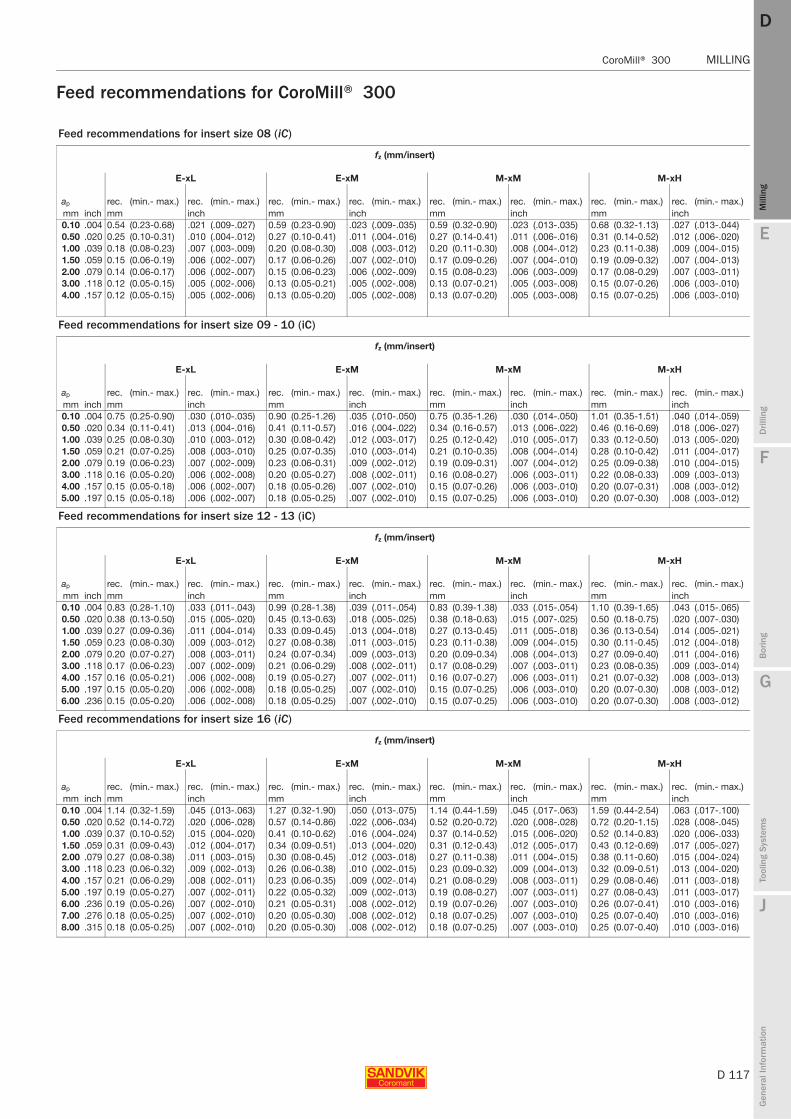
E
D 117
Mill
ing
Drilli
ng
F
Bor
ing
G
Tool
ing
Syst
ems
J
Gen
eral
Info
rmat
ion
DD
Mill
ing
CoroMill® 300 MILLING
MILLING CoroMill® 300
Feed recommendations for CoroMill® 300
Feed recommendations for insert size 08 (iC)
fz (mm/insert)
E-xL E-xM M-xM M-xH
ap rec. (min.- max.) rec. (min.- max.) rec. (min.- max.) rec. (min.- max.) rec. (min.- max.) rec. (min.- max.) rec. (min.- max.) rec. (min.- max.)mm inch mm inch mm inch mm inch mm inch0.10 .004 0.54 (0.23-0.68) .021 (.009-.027) 0.59 (0.23-0.90) .023 (.009-.035) 0.59 (0.32-0.90) .023 (.013-.035) 0.68 (0.32-1.13) .027 (.013-.044)0.50 .020 0.25 (0.10-0.31) .010 (.004-.012) 0.27 (0.10-0.41) .011 (.004-.016) 0.27 (0.14-0.41) .011 (.006-.016) 0.31 (0.14-0.52) .012 (.006-.020)1.00 .039 0.18 (0.08-0.23) .007 (.003-.009) 0.20 (0.08-0.30) .008 (.003-.012) 0.20 (0.11-0.30) .008 (.004-.012) 0.23 (0.11-0.38) .009 (.004-.015)1.50 .059 0.15 (0.06-0.19) .006 (.002-.007) 0.17 (0.06-0.26) .007 (.002-.010) 0.17 (0.09-0.26) .007 (.004-.010) 0.19 (0.09-0.32) .007 (.004-.013)2.00 .079 0.14 (0.06-0.17) .006 (.002-.007) 0.15 (0.06-0.23) .006 (.002-.009) 0.15 (0.08-0.23) .006 (.003-.009) 0.17 (0.08-0.29) .007 (.003-.011)3.00 .118 0.12 (0.05-0.15) .005 (.002-.006) 0.13 (0.05-0.21) .005 (.002-.008) 0.13 (0.07-0.21) .005 (.003-.008) 0.15 (0.07-0.26) .006 (.003-.010)4.00 .157 0.12 (0.05-0.15) .005 (.002-.006) 0.13 (0.05-0.20) .005 (.002-.008) 0.13 (0.07-0.20) .005 (.003-.008) 0.15 (0.07-0.25) .006 (.003-.010)
Feed recommendations for insert size 09 - 10 (iC)
fz (mm/insert)
E-xL E-xM M-xM M-xH
ap rec. (min.- max.) rec. (min.- max.) rec. (min.- max.) rec. (min.- max.) rec. (min.- max.) rec. (min.- max.) rec. (min.- max.) rec. (min.- max.)mm inch mm inch mm inch mm inch mm inch0.10 .004 0.75 (0.25-0.90) .030 (.010-.035) 0.90 (0.25-1.26) .035 (.010-.050) 0.75 (0.35-1.26) .030 (.014-.050) 1.01 (0.35-1.51) .040 (.014-.059)0.50 .020 0.34 (0.11-0.41) .013 (.004-.016) 0.41 (0.11-0.57) .016 (.004-.022) 0.34 (0.16-0.57) .013 (.006-.022) 0.46 (0.16-0.69) .018 (.006-.027)1.00 .039 0.25 (0.08-0.30) .010 (.003-.012) 0.30 (0.08-0.42) .012 (.003-.017) 0.25 (0.12-0.42) .010 (.005-.017) 0.33 (0.12-0.50) .013 (.005-.020)1.50 .059 0.21 (0.07-0.25) .008 (.003-.010) 0.25 (0.07-0.35) .010 (.003-.014) 0.21 (0.10-0.35) .008 (.004-.014) 0.28 (0.10-0.42) .011 (.004-.017)2.00 .079 0.19 (0.06-0.23) .007 (.002-.009) 0.23 (0.06-0.31) .009 (.002-.012) 0.19 (0.09-0.31) .007 (.004-.012) 0.25 (0.09-0.38) .010 (.004-.015)3.00 .118 0.16 (0.05-0.20) .006 (.002-.008) 0.20 (0.05-0.27) .008 (.002-.011) 0.16 (0.08-0.27) .006 (.003-.011) 0.22 (0.08-0.33) .009 (.003-.013)4.00 .157 0.15 (0.05-0.18) .006 (.002-.007) 0.18 (0.05-0.26) .007 (.002-.010) 0.15 (0.07-0.26) .006 (.003-.010) 0.20 (0.07-0.31) .008 (.003-.012)5.00 .197 0.15 (0.05-0.18) .006 (.002-.007) 0.18 (0.05-0.25) .007 (.002-.010) 0.15 (0.07-0.25) .006 (.003-.010) 0.20 (0.07-0.30) .008 (.003-.012)
Feed recommendations for insert size 12 - 13 (iC)
fz (mm/insert)
E-xL E-xM M-xM M-xH
ap rec. (min.- max.) rec. (min.- max.) rec. (min.- max.) rec. (min.- max.) rec. (min.- max.) rec. (min.- max.) rec. (min.- max.) rec. (min.- max.)mm inch mm inch mm inch mm inch mm inch0.10 .004 0.83 (0.28-1.10) .033 (.011-.043) 0.99 (0.28-1.38) .039 (.011-.054) 0.83 (0.39-1.38) .033 (.015-.054) 1.10 (0.39-1.65) .043 (.015-.065)0.50 .020 0.38 (0.13-0.50) .015 (.005-.020) 0.45 (0.13-0.63) .018 (.005-.025) 0.38 (0.18-0.63) .015 (.007-.025) 0.50 (0.18-0.75) .020 (.007-.030)1.00 .039 0.27 (0.09-0.36) .011 (.004-.014) 0.33 (0.09-0.45) .013 (.004-.018) 0.27 (0.13-0.45) .011 (.005-.018) 0.36 (0.13-0.54) .014 (.005-.021)1.50 .059 0.23 (0.08-0.30) .009 (.003-.012) 0.27 (0.08-0.38) .011 (.003-.015) 0.23 (0.11-0.38) .009 (.004-.015) 0.30 (0.11-0.45) .012 (.004-.018)2.00 .079 0.20 (0.07-0.27) .008 (.003-.011) 0.24 (0.07-0.34) .009 (.003-.013) 0.20 (0.09-0.34) .008 (.004-.013) 0.27 (0.09-0.40) .011 (.004-.016)3.00 .118 0.17 (0.06-0.23) .007 (.002-.009) 0.21 (0.06-0.29) .008 (.002-.011) 0.17 (0.08-0.29) .007 (.003-.011) 0.23 (0.08-0.35) .009 (.003-.014)4.00 .157 0.16 (0.05-0.21) .006 (.002-.008) 0.19 (0.05-0.27) .007 (.002-.011) 0.16 (0.07-0.27) .006 (.003-.011) 0.21 (0.07-0.32) .008 (.003-.013)5.00 .197 0.15 (0.05-0.20) .006 (.002-.008) 0.18 (0.05-0.25) .007 (.002-.010) 0.15 (0.07-0.25) .006 (.003-.010) 0.20 (0.07-0.30) .008 (.003-.012)6.00 .236 0.15 (0.05-0.20) .006 (.002-.008) 0.18 (0.05-0.25) .007 (.002-.010) 0.15 (0.07-0.25) .006 (.003-.010) 0.20 (0.07-0.30) .008 (.003-.012)
Feed recommendations for insert size 16 (iC)
fz (mm/insert)
E-xL E-xM M-xM M-xH
ap rec. (min.- max.) rec. (min.- max.) rec. (min.- max.) rec. (min.- max.) rec. (min.- max.) rec. (min.- max.) rec. (min.- max.) rec. (min.- max.)mm inch mm inch mm inch mm inch mm inch0.10 .004 1.14 (0.32-1.59) .045 (.013-.063) 1.27 (0.32-1.90) .050 (.013-.075) 1.14 (0.44-1.59) .045 (.017-.063) 1.59 (0.44-2.54) .063 (.017-.100)0.50 .020 0.52 (0.14-0.72) .020 (.006-.028) 0.57 (0.14-0.86) .022 (.006-.034) 0.52 (0.20-0.72) .020 (.008-.028) 0.72 (0.20-1.15) .028 (.008-.045)1.00 .039 0.37 (0.10-0.52) .015 (.004-.020) 0.41 (0.10-0.62) .016 (.004-.024) 0.37 (0.14-0.52) .015 (.006-.020) 0.52 (0.14-0.83) .020 (.006-.033)1.50 .059 0.31 (0.09-0.43) .012 (.004-.017) 0.34 (0.09-0.51) .013 (.004-.020) 0.31 (0.12-0.43) .012 (.005-.017) 0.43 (0.12-0.69) .017 (.005-.027)2.00 .079 0.27 (0.08-0.38) .011 (.003-.015) 0.30 (0.08-0.45) .012 (.003-.018) 0.27 (0.11-0.38) .011 (.004-.015) 0.38 (0.11-0.60) .015 (.004-.024)3.00 .118 0.23 (0.06-0.32) .009 (.002-.013) 0.26 (0.06-0.38) .010 (.002-.015) 0.23 (0.09-0.32) .009 (.004-.013) 0.32 (0.09-0.51) .013 (.004-.020)4.00 .157 0.21 (0.06-0.29) .008 (.002-.011) 0.23 (0.06-0.35) .009 (.002-.014) 0.21 (0.08-0.29) .008 (.003-.011) 0.29 (0.08-0.46) .011 (.003-.018)5.00 .197 0.19 (0.05-0.27) .007 (.002-.011) 0.22 (0.05-0.32) .009 (.002-.013) 0.19 (0.08-0.27) .007 (.003-.011) 0.27 (0.08-0.43) .011 (.003-.017)6.00 .236 0.19 (0.05-0.26) .007 (.002-.010) 0.21 (0.05-0.31) .008 (.002-.012) 0.19 (0.07-0.26) .007 (.003-.010) 0.26 (0.07-0.41) .010 (.003-.016)7.00 .276 0.18 (0.05-0.25) .007 (.002-.010) 0.20 (0.05-0.30) .008 (.002-.012) 0.18 (0.07-0.25) .007 (.003-.010) 0.25 (0.07-0.40) .010 (.003-.016)8.00 .315 0.18 (0.05-0.25) .007 (.002-.010) 0.20 (0.05-0.30) .008 (.002-.012) 0.18 (0.07-0.25) .007 (.003-.010) 0.25 (0.07-0.40) .010 (.003-.016)
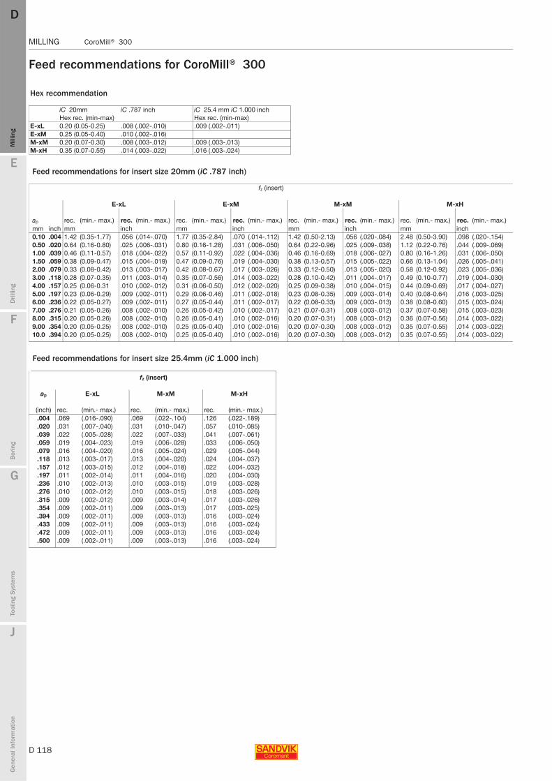
D 118
MILLING CoroMill® 300
E
Mill
ing
Drilli
ng
F
Bor
ing
G
Tool
ing
Syst
ems
J
Gen
eral
Info
rmat
ion
DDM
illin
g
MILLING CoroMill® 300
Feed recommendations for CoroMill® 300
Hex recommendation
iC 20mm iC .787 inch iC 25.4 mm iC 1.000 inch Hex rec. (min-max) Hex rec. (min-max)
E-xL 0.20 (0.05-0.25) .008 (.002-.010) .009 (.002-.011)E-xM 0.25 (0.05-0.40) .010 (.002-.016)M-xM 0.20 (0.07-0.30) .008 (.003-.012) .009 (.003-.013)M-xH 0.35 (0.07-0.55) .014 (.003-.022) .016 (.003-.024)
Feed recommendations for insert size 20mm (iC .787 inch)
fz (insert)
E-xL E-xM M-xM M-xH
ap rec. (min.- max.) rec. (min.- max.) rec. (min.- max.) rec. (min.- max.) rec. (min.- max.) rec. (min.- max.) rec. (min.- max.) rec. (min.- max.)mm inch mm inch mm inch mm inch mm inch0.10 .004 1.42 (0.35-1.77) .056 (.014-.070) 1.77 (0.35-2.84) .070 (.014-.112) 1.42 (0.50-2.13) .056 (.020-.084) 2.48 (0.50-3.90) .098 (.020-.154)0.50 .020 0.64 (0.16-0.80) .025 (.006-.031) 0.80 (0.16-1.28) .031 (.006-.050) 0.64 (0.22-0.96) .025 (.009-.038) 1.12 (0.22-0.76) .044 (.009-.069)1.00 .039 0.46 (0.11-0.57) .018 (.004-.022) 0.57 (0.11-0.92) .022 (.004-.036) 0.46 (0.16-0.69) .018 (.006-.027) 0.80 (0.16-1.26) .031 (.006-.050)1.50 .059 0.38 (0.09-0.47) .015 (.004-.019) 0.47 (0.09-0.76) .019 (.004-.030) 0.38 (0.13-0.57) .015 (.005-.022) 0.66 (0.13-1.04) .026 (.005-.041)2.00 .079 0.33 (0.08-0.42) .013 (.003-.017) 0.42 (0.08-0.67) .017 (.003-.026) 0.33 (0.12-0.50) .013 (.005-.020) 0.58 (0.12-0.92) .023 (.005-.036)3.00 .118 0.28 (0.07-0.35) .011 (.003-.014) 0.35 (0.07-0.56) .014 (.003-.022) 0.28 (0.10-0.42) .011 (.004-.017) 0.49 (0.10-0.77) .019 (.004-.030)4.00 .157 0.25 (0.06-0.31 .010 (.002-.012) 0.31 (0.06-0.50) .012 (.002-.020) 0.25 (0.09-0.38) .010 (.004-.015) 0.44 (0.09-0.69) .017 (.004-.027)5.00 .197 0.23 (0.06-0.29) .009 (.002-.011) 0.29 (0.06-0.46) .011 (.002-.018) 0.23 (0.08-0.35) .009 (.003-.014) 0.40 (0.08-0.64) .016 (.003-.025)6.00 .236 0.22 (0.05-0.27) .009 (.002-.011) 0.27 (0.05-0.44) .011 (.002-.017) 0.22 (0.08-0.33) .009 (.003-.013) 0.38 (0.08-0.60) .015 (.003-.024)7.00 .276 0.21 (0.05-0.26) .008 (.002-.010) 0.26 (0.05-0.42) .010 (.002-.017) 0.21 (0.07-0.31) .008 (.003-.012) 0.37 (0.07-0.58) .015 (.003-.023)8.00 .315 0.20 (0.05-0.26) .008 (.002-.010) 0.26 (0.05-0.41) .010 (.002-.016) 0.20 (0.07-0.31) .008 (.003-.012) 0.36 (0.07-0.56) .014 (.003-.022)9.00 .354 0.20 (0.05-0.25) .008 (.002-.010) 0.25 (0.05-0.40) .010 (.002-.016) 0.20 (0.07-0.30) .008 (.003-.012) 0.35 (0.07-0.55) .014 (.003-.022)10.0 .394 0.20 (0.05-0.25) .008 (.002-.010) 0.25 (0.05-0.40) .010 (.002-.016) 0.20 (0.07-0.30) .008 (.003-.012) 0.35 (0.07-0.55) .014 (.003-.022)
Feed recommendations for insert size 25.4mm (iC 1.000 inch)
fz (insert)
ap E-xL M-xM M-xH
(inch) rec. (min.- max.) rec. (min.- max.) rec. (min.- max.).004 .069 (.016-.090) .069 (.022-.104) .126 (.022-.189).020 .031 (.007-.040) .031 (.010-.047) .057 (.010-.085).039 .022 (.005-.028) .022 (.007-.033) .041 (.007-.061).059 .019 (.004-.023) .019 (.006-.028) .033 (.006-.050).079 .016 (.004-.020) .016 (.005-.024) .029 (.005-.044).118 .013 (.003-.017) .013 (.004-.020) .024 (.004-.037).157 .012 (.003-.015) .012 (.004-.018) .022 (.004-.032).197 .011 (.002-.014) .011 (.004-.016) .020 (.004-.030).236 .010 (.002-.013) .010 (.003-.015) .019 (.003-.028).276 .010 (.002-.012) .010 (.003-.015) .018 (.003-.026).315 .009 (.002-.012) .009 (.003-.014) .017 (.003-.026).354 .009 (.002-.011) .009 (.003-.013) .017 (.003-.025).394 .009 (.002-.011) .009 (.003-.013) .016 (.003-.024).433 .009 (.002-.011) .009 (.003-.013) .016 (.003-.024).472 .009 (.002-.011) .009 (.003-.013) .016 (.003-.024).500 .009 (.002-.011) .009 (.003-.013) .016 (.003-.024)
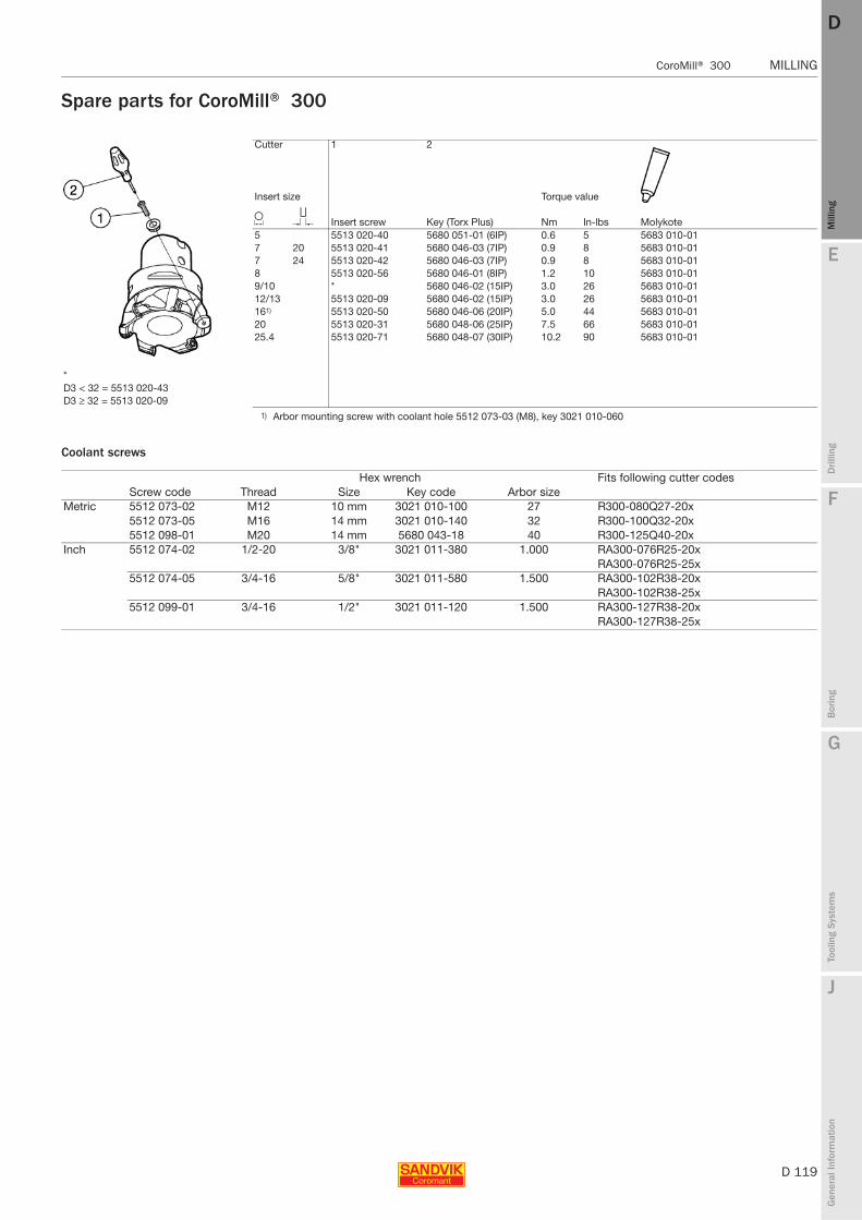
E
D 119
Mill
ing
Drilli
ng
F
Bor
ing
G
Tool
ing
Syst
ems
J
Gen
eral
Info
rmat
ion
DD
Mill
ing
CoroMill® 300 MILLING
MILLING CoroMill® 300
Spare parts for CoroMill® 300
Coolant screws
Cutter 1 2
Insert size Torque value
L T Insert screw Key (Torx Plus) Nm In-lbs Molykote5 5513 020-40 5680 051-01 (6IP) 0.6 5 5683 010-017 20 5513 020-41 5680 046-03 (7IP) 0.9 8 5683 010-017 24 5513 020-42 5680 046-03 (7IP) 0.9 8 5683 010-018 5513 020-56 5680 046-01 (8IP) 1.2 10 5683 010-019/10 * 5680 046-02 (15IP) 3.0 26 5683 010-0112/13 5513 020-09 5680 046-02 (15IP) 3.0 26 5683 010-01161) 5513 020-50 5680 046-06 (20IP) 5.0 44 5683 010-0120 5513 020-31 5680 048-06 (25IP) 7.5 66 5683 010-0125.4 5513 020-71 5680 048-07 (30IP) 10.2 90 5683 010-01
*D3 < 32 = 5513 020-43D3 ≥ 32 = 5513 020-09
1) Arbor mounting screw with coolant hole 5512 073-03 (M8), key 3021 010-060
Hex wrench Fits following cutter codesScrew code Thread Size Key code Arbor size
Metric 5512 073-02 M12 10 mm 3021 010-100 27 R300-080Q27-20x5512 073-05 M16 14 mm 3021 010-140 32 R300-100Q32-20x5512 098-01 M20 14 mm 5680 043-18 40 R300-125Q40-20x
Inch 5512 074-02 1/2-20 3/8" 3021 011-380 1.000 RA300-076R25-20xRA300-076R25-25x
5512 074-05 3/4-16 5/8" 3021 011-580 1.500 RA300-102R38-20xRA300-102R38-25x
5512 099-01 3/4-16 1/2" 3021 011-120 1.500 RA300-127R38-20xRA300-127R38-25x
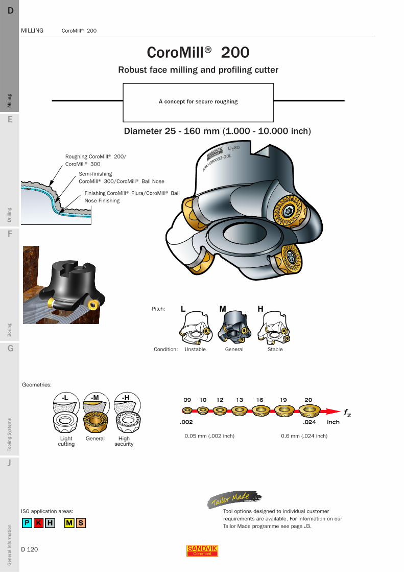
D 120
MILLING CoroMill® 200
E
Mill
ing
Drilli
ng
F
Bor
ing
G
Tool
ing
Syst
ems
J
Gen
eral
Info
rmat
ion
DDM
illin
g
MILLING CoroMill® 200
Geometries:
Lightcutting
General Highsecurity
CoroMill® 200 Robust face milling and profiling cutter
A concept for secure roughing
Diameter 25 - 160 mm (1.000 - 10.000 inch)
Roughing CoroMill® 200/CoroMill® 300
Semi-finishing CoroMill® 300/CoroMill® Ball Nose
Finishing CoroMill® Plura/CoroMill® Ball Nose Finishing
Pitch:
Condition: GeneralUnstable Stable
Tool options designed to individual customer requirements are available. For information on our Tailor Made programme see page J3.
ISO application areas:
0.6 mm (.024 inch)0.05 mm (.002 inch)
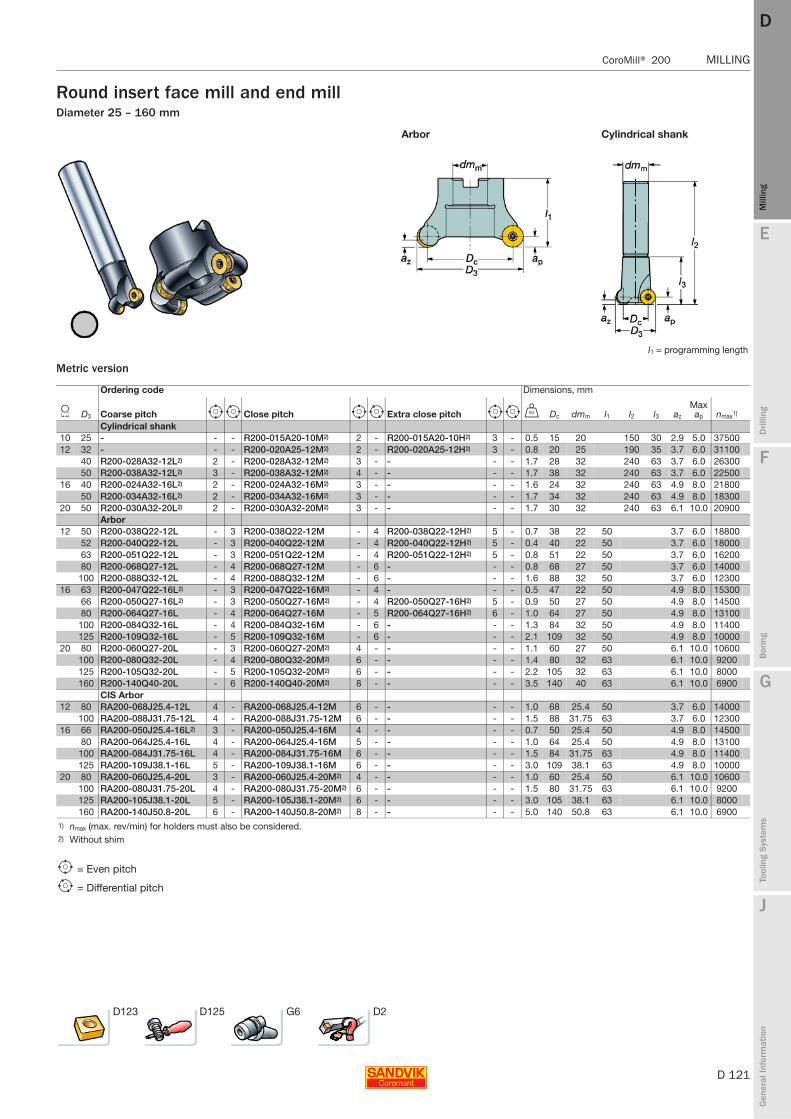
E
D 121
Mill
ing
Drilli
ng
F
Bor
ing
G
Tool
ing
Syst
ems
J
Gen
eral
Info
rmat
ion
DD
Mill
ing
CoroMill® 200 MILLING
MILLING CoroMill® 200
Round insert face mill and end millDiameter 25 – 160 mm
Metric version
Arbor Cylindrical shank
l1 = programming length
Ordering code Dimensions, mm
L D3 Coarse pitch e i Close pitch e i Extra close pitch e i U Dc dmm l1 l2 l3 az
Max ap nmax1)
Cylindrical shank10 25 - - - R200-015A20-10M2) 2 - R200-015A20-10H2) 3 - 0.5 15 20 150 30 2.9 5.0 3750012 32 - - - R200-020A25-12M2) 2 - R200-020A25-12H2) 3 - 0.8 20 25 190 35 3.7 6.0 31100
40 R200-028A32-12L2) 2 - R200-028A32-12M2) 3 - - - - 1.7 28 32 240 63 3.7 6.0 2630050 R200-038A32-12L2) 3 - R200-038A32-12M2) 4 - - - - 1.7 38 32 240 63 3.7 6.0 22500
16 40 R200-024A32-16L2) 2 - R200-024A32-16M2) 3 - - - - 1.6 24 32 240 63 4.9 8.0 2180050 R200-034A32-16L2) 2 - R200-034A32-16M2) 3 - - - - 1.7 34 32 240 63 4.9 8.0 18300
20 50 R200-030A32-20L2) 2 - R200-030A32-20M2) 3 - - - - 1.7 30 32 240 63 6.1 10.0 20900Arbor
12 50 R200-038Q22-12L - 3 R200-038Q22-12M - 4 R200-038Q22-12H2) 5 - 0.7 38 22 50 3.7 6.0 1880052 R200-040Q22-12L - 3 R200-040Q22-12M - 4 R200-040Q22-12H2) 5 - 0.4 40 22 50 3.7 6.0 1800063 R200-051Q22-12L - 3 R200-051Q22-12M - 4 R200-051Q22-12H2) 5 - 0.8 51 22 50 3.7 6.0 1620080 R200-068Q27-12L - 4 R200-068Q27-12M - 6 - - - 0.8 68 27 50 3.7 6.0 14000
100 R200-088Q32-12L - 4 R200-088Q32-12M - 6 - - - 1.6 88 32 50 3.7 6.0 1230016 63 R200-047Q22-16L2) - 3 R200-047Q22-16M2) - 4 - - - 0.5 47 22 50 4.9 8.0 15300
66 R200-050Q27-16L2) - 3 R200-050Q27-16M2) - 4 R200-050Q27-16H2) 5 - 0.9 50 27 50 4.9 8.0 1450080 R200-064Q27-16L - 4 R200-064Q27-16M - 5 R200-064Q27-16H2) 6 - 1.0 64 27 50 4.9 8.0 13100
100 R200-084Q32-16L - 4 R200-084Q32-16M - 6 - - - 1.3 84 32 50 4.9 8.0 11400125 R200-109Q32-16L - 5 R200-109Q32-16M - 6 - - - 2.1 109 32 50 4.9 8.0 10000
20 80 R200-060Q27-20L - 3 R200-060Q27-20M2) 4 - - - - 1.1 60 27 50 6.1 10.0 10600100 R200-080Q32-20L - 4 R200-080Q32-20M2) 6 - - - - 1.4 80 32 63 6.1 10.0 9200125 R200-105Q32-20L - 5 R200-105Q32-20M2) 6 - - - - 2.2 105 32 63 6.1 10.0 8000160 R200-140Q40-20L - 6 R200-140Q40-20M2) 8 - - - - 3.5 140 40 63 6.1 10.0 6900
CIS Arbor12 80 RA200-068J25.4-12L 4 - RA200-068J25.4-12M 6 - - - - 1.0 68 25.4 50 3.7 6.0 14000
100 RA200-088J31.75-12L 4 - RA200-088J31.75-12M 6 - - - - 1.5 88 31.75 63 3.7 6.0 1230016 66 RA200-050J25.4-16L2) 3 - RA200-050J25.4-16M 4 - - - - 0.7 50 25.4 50 4.9 8.0 14500
80 RA200-064J25.4-16L 4 - RA200-064J25.4-16M 5 - - - - 1.0 64 25.4 50 4.9 8.0 13100100 RA200-084J31.75-16L 4 - RA200-084J31.75-16M 6 - - - - 1.5 84 31.75 63 4.9 8.0 11400125 RA200-109J38.1-16L 5 - RA200-109J38.1-16M 6 - - - - 3.0 109 38.1 63 4.9 8.0 10000
20 80 RA200-060J25.4-20L 3 - RA200-060J25.4-20M2) 4 - - - - 1.0 60 25.4 50 6.1 10.0 10600100 RA200-080J31.75-20L 4 - RA200-080J31.75-20M2) 6 - - - - 1.5 80 31.75 63 6.1 10.0 9200125 RA200-105J38.1-20L 5 - RA200-105J38.1-20M2) 6 - - - - 3.0 105 38.1 63 6.1 10.0 8000160 RA200-140J50.8-20L 6 - RA200-140J50.8-20M2) 8 - - - - 5.0 140 50.8 63 6.1 10.0 6900
1) nmax (max. rev/min) for holders must also be considered.2) Without shim
e = Even pitch
i = Differential pitch
D123 D125 G6 D2
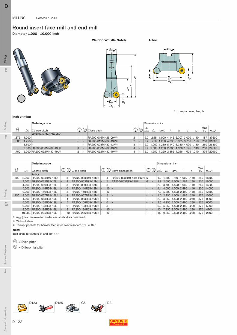
D 122
MILLING CoroMill® 200
E
Mill
ing
Drilli
ng
F
Bor
ing
G
Tool
ing
Syst
ems
J
Gen
eral
Info
rmat
ion
DDM
illin
g
MILLING CoroMill® 200
Round insert face mill and end millDiameter 1.000 - 10.000 inch
Inch version
Weldon/Whistle Notch Arbor
l1 = programming length
Ordering code Dimensions, inch
K D3 Coarse pitch e i Close pitch e i V Dc dmm l1 l2 l3 az
Max ap nmax1)
Whistle Notch/Weldon.375 1.000 - - - RA200-016MN25-09M2) 2 - 2.2 .625 1.000 4.146 5.207 3.000 .110 .187 37500.500 1.250 - - - RA200-019MN32-13M2) 2 - 2.2 .750 1.250 4.896 6.035 3.750 .150 .250 31000
1.500 - - - RA200-025MN32-13M2) 3 - 2.2 1.000 1.250 5.140 6.280 4.000 .150 .250 263002.000 RA200-038MN32-13L2) 3 - RA200-038MN32-13M2) 4 - 2.2 1.500 1.250 2.886 4.026 1.125 .140 .250 22500
.750 2.000 RA200-032MN32-19L2) 2 - RA200-032MN32-19M2) 3 - 2.2 1.250 1.250 2.886 4.026 1.625 .240 .375 20900
Ordering code Dimensions, inch
K D3 Coarse pitch e i Close pitch e i Extra close pitch e i V Dc dmm l1 az
Max ap nmax1)
Arbor.500 2.000 RA200-038R19-13L2) - 3 RA200-038R19-13M2) - 4 RA200-038R19-13H-HD2)3) 5 - 1.0 1.500 .750 1.969 .140 .250 18800
3.000 RA200-063R25-13L - 4 RA200-063R25-13M - 5 RA200-063R25-13H2) 6 - 2.2 2.500 1.000 1.969 .140 .250 180004.000 RA200-089R38-13L - 5 RA200-089R38-13M - 8 - - - 2.2 3.500 1.500 1.969 .140 .250 162005.000 RA200-114R38-13L - 6 RA200-114R38-13M - 10 - - - 4.4 4.500 1.500 2.480 .140 .250 140006.000 RA200-140R38-13L - 8 RA200-140R38-13M - 12 - - - 7.6 5.500 1.500 2.480 .140 .250 12300
.750 3.000 RA200-057R25-19L2) - 4 RA200-057R25-19M2) - 5 - - - 1.0 2.250 1.000 1.969 .240 .375 106004.000 RA200-083R38-19L - 4 RA200-083R38-19M2) - 6 - - - 2.2 3.250 1.500 2.480 .240 .375 92005.000 RA200-108R38-19L - 5 RA200-108R38-19M2) - 6 - - - 3.3 4.250 1.500 2.480 .230 .375 80006.000 RA200-133R38-19L - 6 RA200-133R38-19M2) - 8 - - - 6.2 5.250 1.500 2.480 .230 .375 69008.000 RA200-184R63-19L - 8 RA200-184R63-19M2) - 10 - - - 13. 7.250 2.500 2.480 .230 .375 4700
10.000 RA200-235R63-19L - 10 RA200-235R63-19M2) - 12 - - - 15. 9.250 2.500 2.480 .230 .375 25001) nmax (max. rev/min) for holders must also be considered.2) Without shim3) Thicker pockets for heavier feed rates over standard-13H cutter
Note:Bolt circle for cutters 8" and 10" = 4"
e = Even pitch
i = Differential pitch
D123 D125 G6 D2

E
D 123
Mill
ing
Drilli
ng
F
Bor
ing
G
Tool
ing
Syst
ems
J
Gen
eral
Info
rmat
ion
DD
Mill
ing
CoroMill® 200 MILLING
MILLING CoroMill® 200
Inserts for CoroMill® 200
Metric version
Cemented carbide/Cermet
Light Medium Heavy
P M K N S H Dimensions,
L Ordering code
GCGCGCGCGC CT GCGCGCGCGCGC CT GCGCGCGC - GCGC - - GCGCGCGCGC - - GCGCGCGCGCGCGC CT
iC s 1025
1030
4220
4230
4240
530
1025
1030
1040
2030
2040
235
530
1020
3040
3220
4220
H13
A10
2510
30H
10F
H13
A10
1010
2510
3020
3020
40H
10F
H13
AS
30T
S40
T10
1010
2510
3030
4042
2053
0
Lig
ht
10 RCHT 10 T3 M0-PL ✩ ★ ✩ ✩ ✩ ✩ ✩ ✩ ✩ ✩ ✩ ★ ✩ ✩ ✩ 10 3.97RCHT 10 T3 M0-ML ✩ ★ ✩ ✩ ✩ 10 3.97RCHT 10 T3 M0-KL ✩ ✩ ✩
12 RCHT 12 04 M0-PL ✩ ★ ✩ ✩ ✩ ✩ ✩ ✩ ✩ ✩ ✩ ★ ✩ ✩ ✩ 12 4.76RCHT 12 04 M0-ML ✩ ★ ✩ ✩ ✩ 12 4.76RCHT 12 04 M0-KL ✩ ✩ ✩ 12 4.76
16 RCHT 16 06 M0-PL ✩ ★ ✩ ✩ ✩ ✩ ✩ ✩ ✩ ✩ 16 6.35RCHT 16 06 M0-ML ✩ ★ ✩ ✩ ✩ 16 6.35RCHT 16 06 M0-KL ✩ ✩ ✩
20 RCHT 20 06 M0-PL ✩ ★ ✩ ✩ ✩ ✩ ✩ ✩ ✩ ✩ 20 6.35RCHT 20 06 M0-ML ✩ ★ ✩ ✩ ✩ 20 6.35RCHT 20 06 M0-KL ✩ ✩ ✩
Med
ium
10 RCKT 10 T3 M0-WM ✩ ✩ ✩ ✩ ✩ ✩ 10 3.97RCKT 10 T3 M0-PM ✩ ✩ ★ ✩ ✩ ✩ ✩ ✩ ★ ★ ✩ ✩ 10 3.97RCKT 10 T3 M0-MM ✩ ★ ✩ ✩ ✩ 10 3.97RCKT 10 T3 M0-KM ✩ ✩ ✩ 10 3.97
12 RCKT 12 04 M0-WM ✩ ✩ ✩ ✩ ✩ ✩ 12 4.76RCKT 12 04 M0-PM ✩ ✩ ★ ✩ ✩ ✩ ✩ ✩ ★ ★ ✩ ✩ 12 4.76RCKT 12 04 M0-MM ✩ ★ ✩ ✩ ✩ 12 4.76RCKT 12 04 M0-KM ★ ✩ ✩ ✩ 12 4.76
16 RCKT 16 06 M0-WM ✩ ✩ ✩ 16 6.35RCKT 16 06 M0-PM ✩ ✩ ★ ✩ ✩ ✩ ✩ ✩ ★ ★ ✩ ✩ 16 6.35RCKT 16 06 M0-MM ✩ ★ ✩ ✩ ✩ 16 6.35RCKT 16 06 M0-KM ✩ ✩ ✩ 16 6.35
20 RCKT 20 06 M0-WM ✩ ✩ ✩ 20 6.35RCKT 20 06 M0-PM ✩ ✩ ★ ✩ ✩ ✩ ✩ ✩ ★ ★ ✩ ✩ 20 6.35RCKT 20 06 M0-MM ✩ ★ ✩ ✩ ✩ 20 6.35RCKT 20 06 M0-KM ✩ ✩ ✩ 20 6.35
Hea
vy
10 RCKT 10 T3 M0-PH ✩ ✩ ✩ ★ ✩ ✩ ✩ ✩ ✩ 10 3.97RCKT 10 T3 M0-KH ✩ ✩ ✩ 10 3.97
12 RCKT 12 04 M0-PH ✩ ✩ ✩ ★ ✩ ✩ ✩ ✩ ✩ 12 4.76RCKT 12 04 M0-KH ✩ ✩ ✩ 12 4.76
16 RCKT 16 06 M0-PH ✩ ✩ ✩ ★ ✩ ✩ ✩ ✩ ✩ 16 6.35RCKT 16 06 M0-KH ✩ ✩ ✩ 16 6.35
20 RCKT 20 06 M0-PH ✩ ✩ ✩ ★ ✩ ✩ ✩ ✩ ✩ 20 6.35RCKT 20 06 M0-KH ✩ ✩ ✩ 20 6.35
P10
P30
P15
P25
P40
P20
M15
M15
M35
M25
M30
M35
M20
K20
K30
K20
K25
K25
N15
N15
N20
N15
S10
S15
S15
S25
S30
S30
S20
S25
S35
H10
H15
H10
H25
H25
H15
★= First choice
D312 D305 D334 D2

D 124
MILLING CoroMill® 200
E
Mill
ing
Drilli
ng
F
Bor
ing
G
Tool
ing
Syst
ems
J
Gen
eral
Info
rmat
ion
DDM
illin
g
MILLING CoroMill® 200
Inserts for CoroMill® 200
Inch version
Cemented carbide/Cermet
Light Medium Heavy
P M K N S H Dimensions, inch
L Ordering code
GC GC GC GC GC GC GC GC GC GC GC GC GC GC - GC GC - - GC GC GC GC GC - - GC GC GC GC GC GC GC
iC s 1025
1030
235
4220
4230
4240
1030
1040
2030
2040
235
3040
3220
4220
H13
A10
2510
30H
10F
H13
A10
1010
2510
3020
3020
40H
10F
H13
AS
30T
S40
T10
1010
2510
3030
4042
20
Lig
ht
09 RCHT 09 T3 00-ML ✩ ✩ ✩ .375 .156RCHT 09 T3 00-PL ✩ ★ ✩ ✩ ✩ ✩ ✩ ✩ ★ ✩ ✩ .375 .156RCHT 09 T3 00-KL ✩ ✩ ✩
13 RCHT 13 04 00-KL ✩ ✩ ✩ .500 .188RCHT 13 04 00-ML ✩ ✩ ✩ ✩ ✩ .500 .188RCHT 13 04 00-PL ✩ ★ ✩ ✩ ✩ ✩ ✩ ✩ ★ ✩ ✩ .500 .188
19 RCHT 19 06 00-ML ✩ ✩ ✩ ✩ ✩ .750 .250RCHT 19 06 00-PL ✩ ★ ✩ ✩ ✩ ✩ ✩ ✩ ✩ .750 .250RCHT 19 06 00-KL ✩ ✩ ✩
Med
ium
09 RCKT 09 T3 00-MM ✩ ✩ ✩ ✩ ✩ .375 .156RCKT 09 T3 00-PM ✩ ✩ ✩ ✩ ✩ ✩ ✩ ✩ ✩ ✩ .375 .156RCKT 09 T3 00-WM ✩ ✩ .375 .156
13 RCKT 13 04 00-KM ✩ ✩ ✩ .500 .188RCKT 13 04 00-MM ✩ ✩ ✩ ✩ ✩ .500 .188RCKT 13 04 00-PM ✩ ✩ ★ ✩ ✩ ✩ ✩ ✩ ★ ★ ✩ ✩ .500 .188RCKT 13 04 00-WM ✩ ✩ ✩ ✩ .500 .188
19 RCKT 19 06 00-KM ✩ ✩ ✩ .750 .250RCKT 19 06 00-MM ✩ ✩ ✩ ✩ ✩ .750 .250RCKT 19 06 00-PM ✩ ✩ ★ ✩ ✩ ✩ ✩ ✩ ★ ★ ✩ ✩ .750 .250RCKT 19 06 00-WM ✩ ✩ ✩ ✩ .750 .250
Hea
vy
09 RCKT 09 T3 00-KH ✩ ✩ .375 .156RCKT 09 T3 00-PH ✩ ✩ ✩ ✩ ✩ ✩ ✩ ✩ ✩ .375 .156
13 RCKT 13 04 00-KH ✩ ✩ ✩ .500 .188RCKT 13 04 00-PH ✩ ✩ ✩ ★ ✩ ✩ ✩ ✩ ✩ .500 .188
19 RCKT 19 06 00-KH ✩ ✩ ✩ .750 .250RCKT 19 06 00-PH ✩ ✩ ✩ ★ ✩ ✩ ✩ ✩ ✩ .750 .250
P10
P30
P40
P15
P25
P40
M15
M35
M25
M30
M35
K30
K20
K25
K25
N15
N15
N20
N15
S10
S15
S15
S25
S30
S30
S20
S25
S35
H10
H15
H10
H25
H25
★= First choice
D312 D305 D334 D2
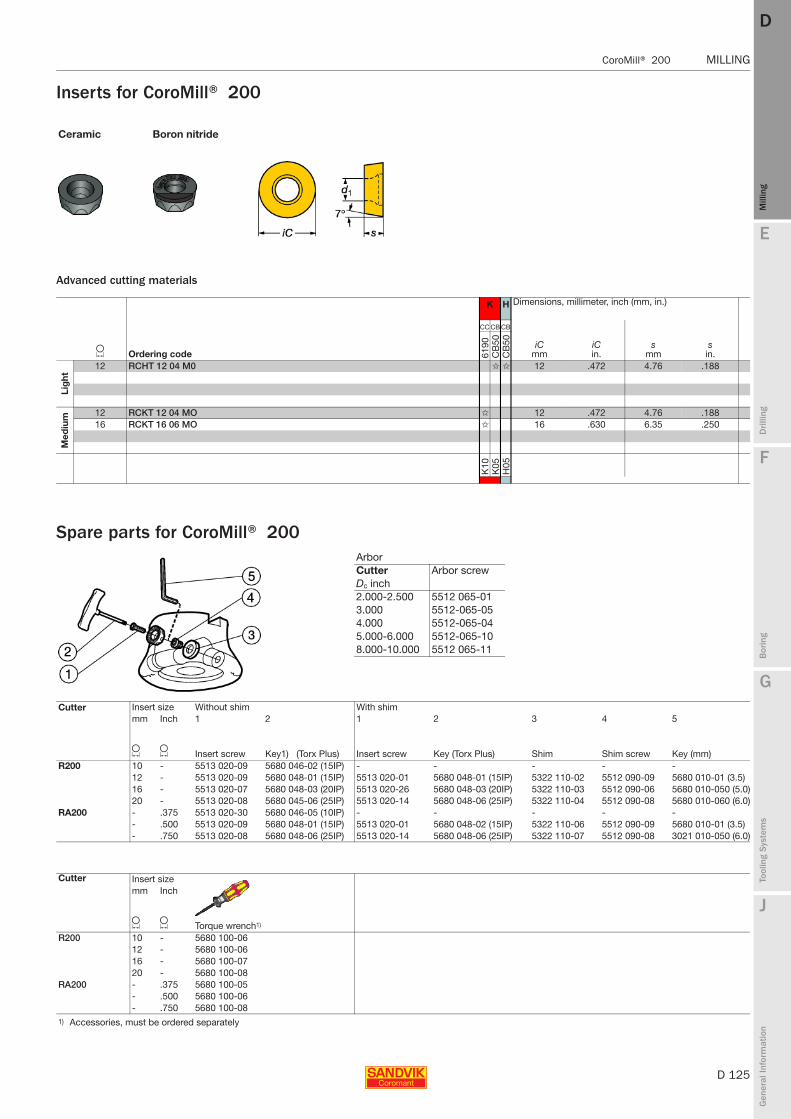
E
D 125
Mill
ing
Drilli
ng
F
Bor
ing
G
Tool
ing
Syst
ems
J
Gen
eral
Info
rmat
ion
DD
Mill
ing
CoroMill® 200 MILLING
MILLING CoroMill® 200
Inserts for CoroMill® 200
Advanced cutting materials
Spare parts for CoroMill® 200
Ceramic Boron nitride
K H Dimensions, millimeter, inch (mm, in.)
L Ordering code
CC CB CB
iCmm
iCin.
smm
sin.61
90C
B50
CB
50
Lig
ht
12 RCHT 12 04 M0 ✩ ✩ 12 .472 4.76 .188
Med
ium 12 RCKT 12 04 MO ✩ 12 .472 4.76 .188
16 RCKT 16 06 MO ✩ 16 .630 6.35 .250
K10
K05
H05
Arbor Cutter Arbor screwDc inch2.000-2.500 5512 065-013.000 5512-065-054.000 5512-065-045.000-6.000 5512-065-108.000-10.000 5512 065-11
Cutter Insert size Without shim With shimmm Inch 1 2 1 2 3 4 5
L L Insert screw Key1) (Torx Plus) Insert screw Key (Torx Plus) Shim Shim screw Key (mm)R200 10 - 5513 020-09 5680 046-02 (15IP) - - - - -
12 - 5513 020-09 5680 048-01 (15IP) 5513 020-01 5680 048-01 (15IP) 5322 110-02 5512 090-09 5680 010-01 (3.5)16 - 5513 020-07 5680 048-03 (20IP) 5513 020-26 5680 048-03 (20IP) 5322 110-03 5512 090-06 5680 010-050 (5.0)20 - 5513 020-08 5680 045-06 (25IP) 5513 020-14 5680 048-06 (25IP) 5322 110-04 5512 090-08 5680 010-060 (6.0)
RA200 - .375 5513 020-30 5680 046-05 (10IP) - - - - -- .500 5513 020-09 5680 048-01 (15IP) 5513 020-01 5680 048-02 (15IP) 5322 110-06 5512 090-09 5680 010-01 (3.5)- .750 5513 020-08 5680 048-06 (25IP) 5513 020-14 5680 048-06 (25IP) 5322 110-07 5512 090-08 3021 010-050 (6.0)
Cutter Insert size mm Inch
L L Torque wrench1)
R200 10 - 5680 100-0612 - 5680 100-0616 - 5680 100-0720 - 5680 100-08
RA200 - .375 5680 100-05- .500 5680 100-06- .750 5680 100-08
1) Accessories, must be ordered separately
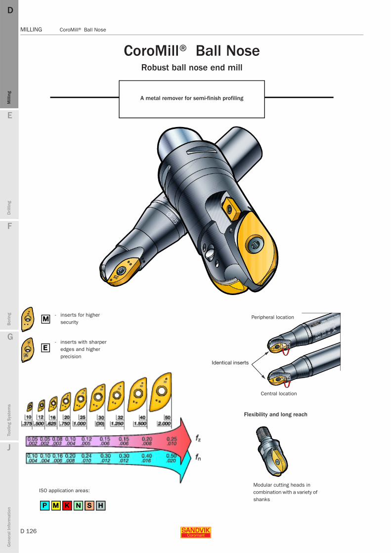
D 126
MILLING CoroMill® Ball Nose
E
Mill
ing
Drilli
ng
F
Bor
ing
G
Tool
ing
Syst
ems
J
Gen
eral
Info
rmat
ion
DDM
illin
g
MILLING CoroMill® Ball Nose
- inserts for higher security
- inserts with sharper edges and higher precision
Flexibility and long reach
Modular cutting heads in combination with a variety of shanks
CoroMill® Ball NoseRobust ball nose end mill
A metal remover for semi-finish profiling
Peripheral location
Identical inserts
Central location
ISO application areas:
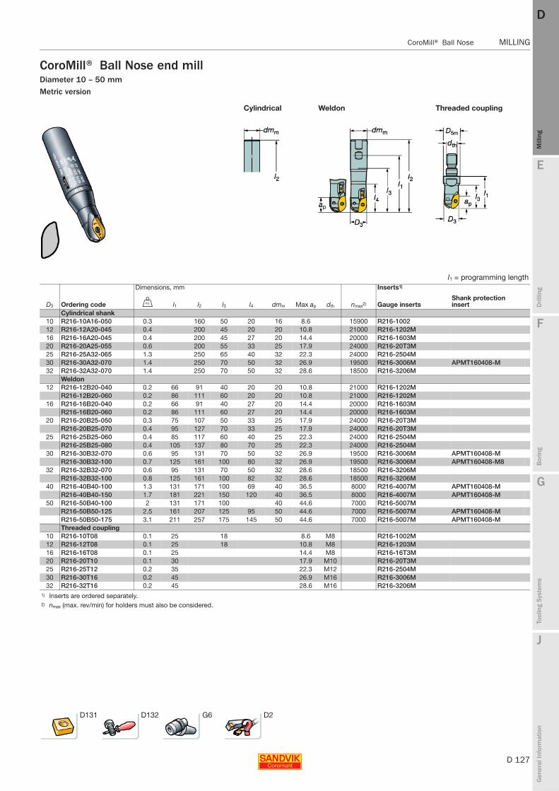
E
D 127
Mill
ing
Drilli
ng
F
Bor
ing
G
Tool
ing
Syst
ems
J
Gen
eral
Info
rmat
ion
DD
Mill
ing
CoroMill® Ball Nose MILLING
MILLING CoroMill® Ball Nose
CoroMill® Ball Nose end millDiameter 10 – 50 mmMetric version
Cylindrical Weldon Threaded coupling
l1 = programming lengthDimensions, mm Inserts1)
D3 Ordering code U l1 l2 l3 l4 dmm Max ap dth nmax2) Gauge insertsShank protection insert
Cylindrical shank10 R216-10A16-050 0.3 160 50 20 16 8.6 15900 R216-100212 R216-12A20-045 0.4 200 45 20 20 10.8 21000 R216-1202M16 R216-16A20-045 0.4 200 45 27 20 14.4 20000 R216-1603M20 R216-20A25-055 0.6 200 55 33 25 17.9 24000 R216-20T3M25 R216-25A32-065 1.3 250 65 40 32 22.3 24000 R216-2504M30 R216-30A32-070 1.4 250 70 50 32 26.9 19500 R216-3006M APMT160408-M32 R216-32A32-070 1.4 250 70 50 32 28.6 18500 R216-3206M
Weldon12 R216-12B20-040 0.2 66 91 40 20 20 10.8 21000 R216-1202M
R216-12B20-060 0.2 86 111 60 20 20 10.8 21000 R216-1202M16 R216-16B20-040 0.2 66 91 40 27 20 14.4 20000 R216-1603M
R216-16B20-060 0.2 86 111 60 27 20 14.4 20000 R216-1603M20 R216-20B25-050 0.3 75 107 50 33 25 17.9 24000 R216-20T3M
R216-20B25-070 0.4 95 127 70 33 25 17.9 24000 R216-20T3M25 R216-25B25-060 0.4 85 117 60 40 25 22.3 24000 R216-2504M
R216-25B25-080 0.4 105 137 80 70 25 22.3 24000 R216-2504M30 R216-30B32-070 0.6 95 131 70 50 32 26.9 19500 R216-3006M APMT160408-M
R216-30B32-100 0.7 125 161 100 80 32 26.9 19500 R216-3006M APMT160408-M832 R216-32B32-070 0.6 95 131 70 50 32 28.6 18500 R216-3206M
R216-32B32-100 0.8 125 161 100 82 32 28.6 18500 R216-3206M40 R216-40B40-100 1.3 131 171 100 69 40 36.5 8000 R216-4007M APMT160408-M
R216-40B40-150 1.7 181 221 150 120 40 36.5 8000 R216-4007M APMT160408-M50 R216-50B40-100 2 131 171 100 40 44.6 7000 R216-5007M
R216-50B50-125 2.5 161 207 125 95 50 44.6 7000 R216-5007M APMT160408-MR216-50B50-175 3.1 211 257 175 145 50 44.6 7000 R216-5007M APMT160408-MThreaded coupling
10 R216-10T08 0.1 25 18 8.6 M8 R216-1002M12 R216-12T08 0.1 25 18 10.8 M8 R216-1203M16 R216-16T08 0.1 25 14.4 M8 R216-16T3M20 R216-20T10 0.1 30 17.9 M10 R216-20T3M25 R216-25T12 0.2 35 22.3 M12 R216-2504M30 R216-30T16 0.2 45 26.9 M16 R216-3006M32 R216-32T16 0.2 45 28.6 M16 R216-3206M
1) Inserts are ordered separately.2) nmax (max. rev/min) for holders must also be considered.
D131 D132 G6 D2
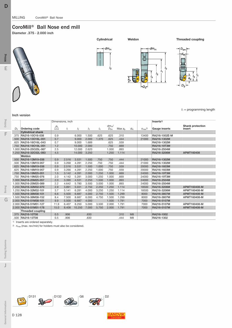
D 128
MILLING CoroMill® Ball Nose
E
Mill
ing
Drilli
ng
F
Bor
ing
G
Tool
ing
Syst
ems
J
Gen
eral
Info
rmat
ion
DDM
illin
g
MILLING CoroMill® Ball Nose
CoroMill® Ball Nose end millDiameter .375 - 2.000 inch
Inch version
Cylindrical Weldon Threaded coupling
l1 = programming length
Dimensions, inch Inserts1)
D3 Ordering code V l1 l2 l3 l4dmm/D5m Max ap dth nmax2) Gauge inserts
Shank protection insert
Cylindrical shank.375 RA216-10O16-038 0.9 6.000 1.500 .625 .625 .310 13400 RA216-1002E-M.500 RA216-13O16L-051 0.7 9.000 2.000 1.370 .625 .444 21000 RA216-1302M.625 RA216-16O16L-043 0.7 9.000 1.689 .625 .559 RA216-1302M.750 RA216-19O19L-051 1.2 10.000 2.000 .750 .669 RA216-19T3M1.000 RA216-25O25L-067 2.5 12.000 2.620 1.000 .893 RA216-2504M1.250 RA216-32O32L-083 4.5 14.000 3.250 1.250 1.114 RA216-3206M APMT160408
Weldon.500 RA216-13M19-038 0.9 2.516 3.531 1.500 .750 .750 .444 21000 RA216-1302M.500 RA216-13M19-057 0.9 3.268 4.281 2.250 .750 .750 .444 21000 RA216-1302M.625 RA216-16M19-038 0.9 2.516 3.531 1.500 1.000 .750 .559 20000 RA216-1603M.625 RA216-16M19-057 0.9 3.266 4.281 2.250 1.000 .750 .559 20000 RA216-1603M.750 RA216-19M25-051 1.5 3.142 4.281 2.000 1.250 1.000 .669 24000 RA216-19T3M.750 RA216-19M25-076 2.0 4.142 5.281 3.000 1.250 1.000 .669 24000 RA216-19T3M1.000 RA216-25M25-057 2.0 3.390 4.531 2.250 1.500 1.000 .893 24000 RA216-2504M1.000 RA216-25M25-089 2.2 4.642 5.780 3.500 3.000 1.000 .893 24000 RA216-2504M1.250 RA216-32M32-070 2.9 3.891 5.031 2.750 2.250 1.250 1.114 18500 RA216-3206M APMT160408-M1.250 RA216-32M32-101 3.7 5.141 6.281 4.000 3.250 1.250 1.114 18500 RA216-3206M APMT160408-M1.500 RA216-38M38-101 6.6 5.500 6.687 4.000 2.750 1.500 1.299 8000 RA216-3807M APMT160408-M1.500 RA216-38M38-152 8.4 7.500 8.687 6.000 4.750 1.500 1.299 8000 RA216-3807M APMT160408-M2.000 RA216-51M38-101 9.9 5.500 6.687 4.000 1.500 1.791 7000 RA216-5107M2.000 RA216-51M51-127 11.9 6.407 8.250 5.000 3.500 2.000 1.791 7000 RA216-5107M APMT160408-M2.000 RA216-51M51-178 15.0 8.408 10.250 7.000 5.750 2.000 1.791 7000 RA216-5107M APMT160408-M
Threaded coupling.375 RA216-10T08 0.5 .906 .630 .310 M8 RA216-1002.500 RA216-13T08 0.5 .906 .630 .444 M8 RA216-1302
1) Inserts are ordered separately.2) nmax (max. rev/min) for holders must also be considered.
D131 D132 G6 D2
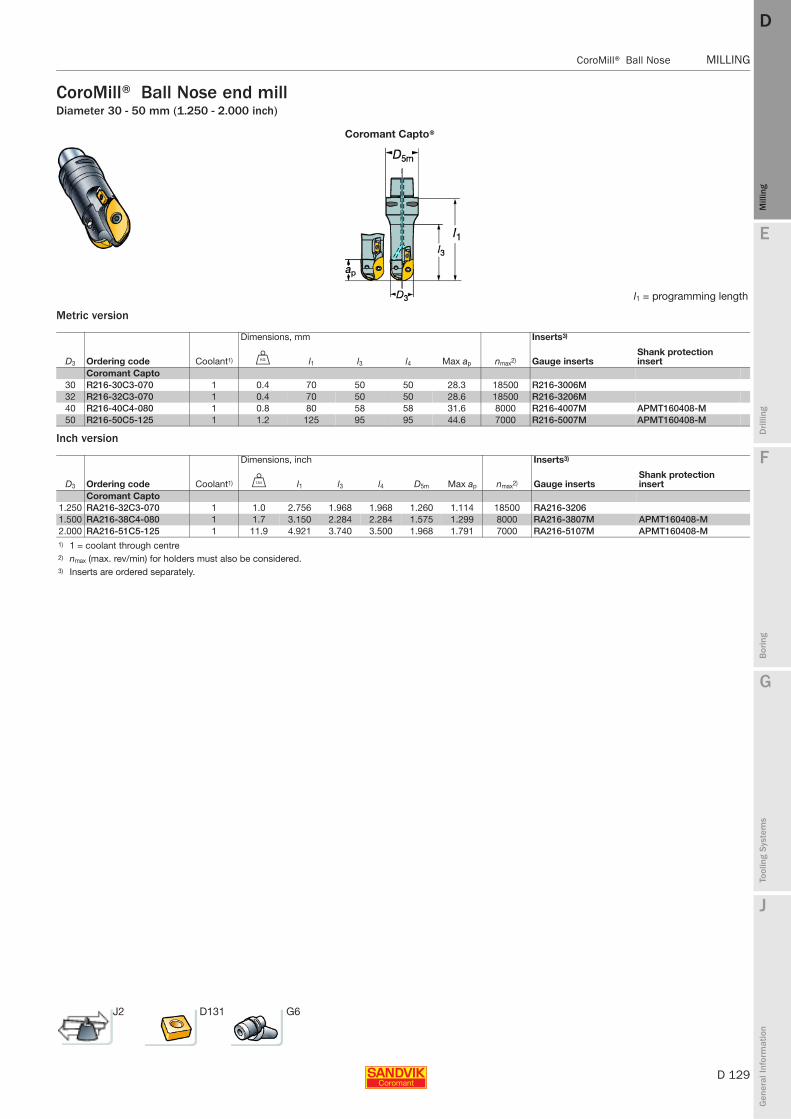
E
D 129
Mill
ing
Drilli
ng
F
Bor
ing
G
Tool
ing
Syst
ems
J
Gen
eral
Info
rmat
ion
DD
Mill
ing
CoroMill® Ball Nose MILLING
MILLING CoroMill® Ball Nose
CoroMill® Ball Nose end millDiameter 30 - 50 mm (1.250 - 2.000 inch)
Metric version
Inch version
Coromant Capto®
l1 = programming length
Dimensions, mm Inserts3)
D3 Ordering code Coolant1) U l1 l3 l4 Max ap nmax2) Gauge insertsShank protection insert
Coromant Capto 30 R216-30C3-070 1 0.4 70 50 50 28.3 18500 R216-3006M32 R216-32C3-070 1 0.4 70 50 50 28.6 18500 R216-3206M40 R216-40C4-080 1 0.8 80 58 58 31.6 8000 R216-4007M APMT160408-M50 R216-50C5-125 1 1.2 125 95 95 44.6 7000 R216-5007M APMT160408-M
Dimensions, inch Inserts3)
D3 Ordering code Coolant1) V l1 l3 l4 D5m Max ap nmax2) Gauge insertsShank protection insert
Coromant Capto 1.250 RA216-32C3-070 1 1.0 2.756 1.968 1.968 1.260 1.114 18500 RA216-32061.500 RA216-38C4-080 1 1.7 3.150 2.284 2.284 1.575 1.299 8000 RA216-3807M APMT160408-M2.000 RA216-51C5-125 1 11.9 4.921 3.740 3.500 1.968 1.791 7000 RA216-5107M APMT160408-M1) 1 = coolant through centre2) nmax (max. rev/min) for holders must also be considered.3) Inserts are ordered separately.
J2 D131 G6
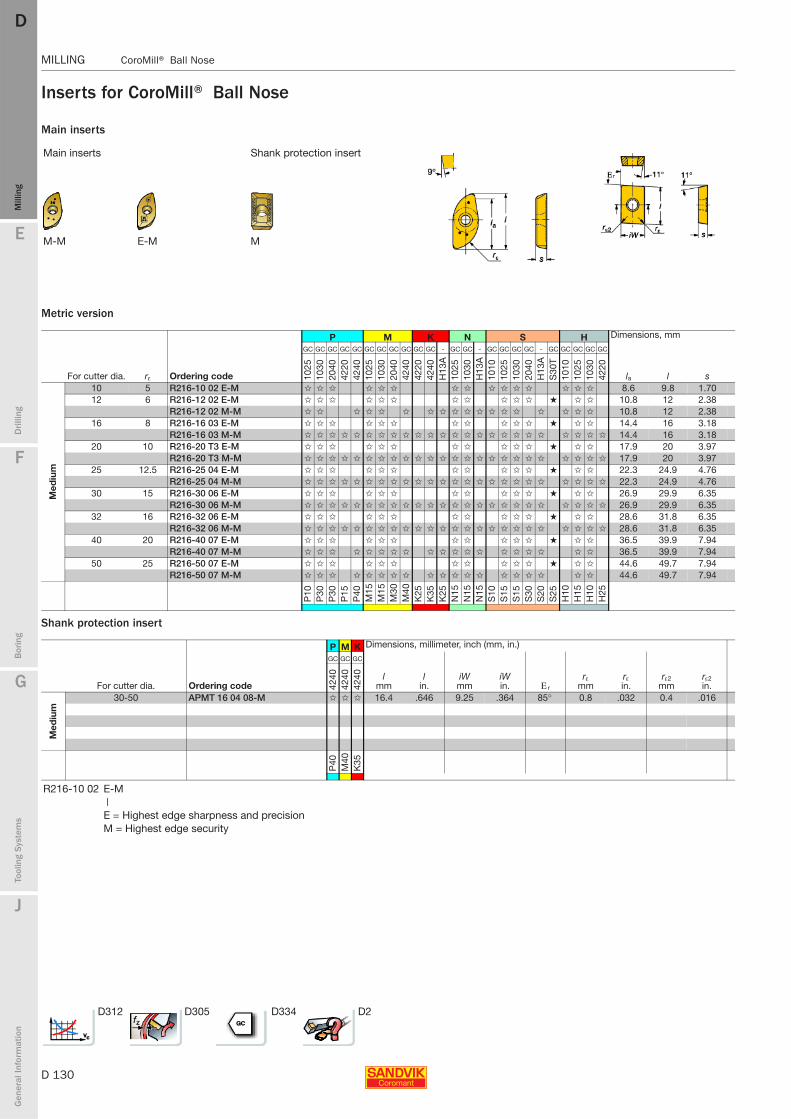
D 130
MILLING CoroMill® Ball Nose
E
Mill
ing
Drilli
ng
F
Bor
ing
G
Tool
ing
Syst
ems
J
Gen
eral
Info
rmat
ion
DDM
illin
g
MILLING CoroMill® Ball Nose
Inserts for CoroMill® Ball Nose
Main inserts
Metric version
Shank protection insert
Main inserts Shank protection insert
M-M E-M M
P M K N S H Dimensions, mm
For cutter dia. rε Ordering code
GC GC GC GC GC GC GC GC GC GC GC - GC GC - GC GC GC GC - GC GC GC GC GC
la l s 1025
1030
2040
4220
4240
1025
1030
2040
4240
4220
4240
H13
A10
2510
30H
13A
1010
1025
1030
2040
H13
AS
30T
1010
1025
1030
4220
Med
ium
10 5 R216-10 02 E-M ✩ ✩ ✩ ✩ ✩ ✩ ✩ ✩ ✩ ✩ ✩ ✩ ✩ ✩ ✩ 8.6 9.8 1.7012 6 R216-12 02 E-M ✩ ✩ ✩ ✩ ✩ ✩ ✩ ✩ ✩ ✩ ✩ ★ ✩ ✩ 10.8 12 2.38
R216-12 02 M-M ✩ ✩ ✩ ✩ ✩ ✩ ✩ ✩ ✩ ✩ ✩ ✩ ✩ ✩ ✩ ✩ ✩ ✩ 10.8 12 2.3816 8 R216-16 03 E-M ✩ ✩ ✩ ✩ ✩ ✩ ✩ ✩ ✩ ✩ ✩ ★ ✩ ✩ 14.4 16 3.18
R216-16 03 M-M ✩ ✩ ✩ ✩ ✩ ✩ ✩ ✩ ✩ ✩ ✩ ✩ ✩ ✩ ✩ ✩ ✩ ✩ ✩ ✩ ✩ ✩ ✩ ✩ 14.4 16 3.1820 10 R216-20 T3 E-M ✩ ✩ ✩ ✩ ✩ ✩ ✩ ✩ ✩ ✩ ✩ ★ ✩ ✩ 17.9 20 3.97
R216-20 T3 M-M ✩ ✩ ✩ ✩ ✩ ✩ ✩ ✩ ✩ ✩ ✩ ✩ ✩ ✩ ✩ ✩ ✩ ✩ ✩ ✩ ✩ ✩ ✩ ✩ 17.9 20 3.9725 12.5 R216-25 04 E-M ✩ ✩ ✩ ✩ ✩ ✩ ✩ ✩ ✩ ✩ ✩ ★ ✩ ✩ 22.3 24.9 4.76
R216-25 04 M-M ✩ ✩ ✩ ✩ ✩ ✩ ✩ ✩ ✩ ✩ ✩ ✩ ✩ ✩ ✩ ✩ ✩ ✩ ✩ ✩ ✩ ✩ ✩ ✩ 22.3 24.9 4.7630 15 R216-30 06 E-M ✩ ✩ ✩ ✩ ✩ ✩ ✩ ✩ ✩ ✩ ✩ ★ ✩ ✩ 26.9 29.9 6.35
R216-30 06 M-M ✩ ✩ ✩ ✩ ✩ ✩ ✩ ✩ ✩ ✩ ✩ ✩ ✩ ✩ ✩ ✩ ✩ ✩ ✩ ✩ ✩ ✩ ✩ ✩ 26.9 29.9 6.3532 16 R216-32 06 E-M ✩ ✩ ✩ ✩ ✩ ✩ ✩ ✩ ✩ ✩ ✩ ★ ✩ ✩ 28.6 31.8 6.35
R216-32 06 M-M ✩ ✩ ✩ ✩ ✩ ✩ ✩ ✩ ✩ ✩ ✩ ✩ ✩ ✩ ✩ ✩ ✩ ✩ ✩ ✩ ✩ ✩ ✩ ✩ 28.6 31.8 6.3540 20 R216-40 07 E-M ✩ ✩ ✩ ✩ ✩ ✩ ✩ ✩ ✩ ✩ ✩ ★ ✩ ✩ 36.5 39.9 7.94
R216-40 07 M-M ✩ ✩ ✩ ✩ ✩ ✩ ✩ ✩ ✩ ✩ ✩ ✩ ✩ ✩ ✩ ✩ ✩ ✩ ✩ 36.5 39.9 7.9450 25 R216-50 07 E-M ✩ ✩ ✩ ✩ ✩ ✩ ✩ ✩ ✩ ✩ ✩ ★ ✩ ✩ 44.6 49.7 7.94
R216-50 07 M-M ✩ ✩ ✩ ✩ ✩ ✩ ✩ ✩ ✩ ✩ ✩ ✩ ✩ ✩ ✩ ✩ ✩ ✩ ✩ 44.6 49.7 7.94
P10
P30
P30
P15
P40
M15
M15
M30
M40
K25
K35
K25
N15
N15
N15
S10
S15
S15
S30
S20
S25
H10
H15
H10
H25
P M K Dimensions, millimeter, inch (mm, in.)
For cutter dia. Ordering code
GC GC GC
lmm
lin.
iWmm
iWin. Ε r
rεmm
rεin.
rε2mm
rε2in.42
4042
4042
40
Med
ium
30-50 APMT 16 04 08-M ✩ ✩ ✩ 16.4 .646 9.25 .364 85° 0.8 .032 0.4 .016
P40
M40
K35
R216-10 02 E-M|E = Highest edge sharpness and precisionM = Highest edge security
D312 D305 D334 D2
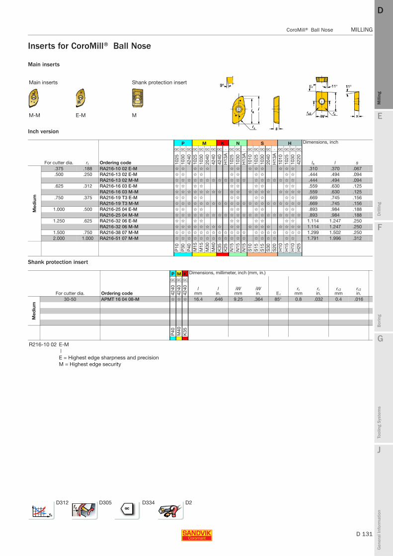
E
D 131
Mill
ing
Drilli
ng
F
Bor
ing
G
Tool
ing
Syst
ems
J
Gen
eral
Info
rmat
ion
DD
Mill
ing
CoroMill® Ball Nose MILLING
MILLING CoroMill® Ball Nose
Inserts for CoroMill® Ball Nose
Main inserts
Inch version
Shank protection insert
Main inserts Shank protection insert
M-M E-M M
P M K N S H Dimensions, inch
For cutter dia. rε Ordering code
GC GC GC GC GC GC GC GC - GC GC - GC GC GC GC - GC GC GC GC
la l s 1025
1030
4240
1025
1030
2040
4240
4240
H13
A10
2510
30H
13A
1010
1025
1030
2040
H13
A10
1010
2510
3042
20
Med
ium
.375 .188 RA216-10 02 E-M ✩ ✩ ✩ ✩ ✩ ✩ ✩ ✩ ✩ ✩ ✩ ✩ ✩ .310 .370 .067
.500 .250 RA216-13 02 E-M ✩ ✩ ✩ ✩ ✩ ✩ ✩ ✩ ✩ ✩ .444 .494 .094RA216-13 02 M-M ✩ ✩ ✩ ✩ ✩ ✩ ✩ ✩ ✩ ✩ ✩ ✩ ✩ ✩ ✩ ✩ ✩ ✩ ✩ .444 .494 .094
.625 .312 RA216-16 03 E-M ✩ ✩ ✩ ✩ ✩ ✩ ✩ ✩ ✩ ✩ .559 .630 .125RA216-16 03 M-M ✩ ✩ ✩ ✩ ✩ ✩ ✩ ✩ ✩ ✩ ✩ ✩ ✩ ✩ ✩ ✩ ✩ ✩ .559 .630 .125
.750 .375 RA216-19 T3 E-M ✩ ✩ ✩ ✩ ✩ ✩ ✩ ✩ ✩ ✩ .669 .745 .156RA216-19 T3 M-M ✩ ✩ ✩ ✩ ✩ ✩ ✩ ✩ ✩ ✩ ✩ ✩ ✩ ✩ ✩ ✩ ✩ ✩ ✩ ✩ ✩ .669 .745 .156
1.000 .500 RA216-25 04 E-M ✩ ✩ ✩ ✩ ✩ ✩ ✩ ✩ ✩ ✩ .893 .984 .188RA216-25 04 M-M ✩ ✩ ✩ ✩ ✩ ✩ ✩ ✩ ✩ ✩ ✩ ✩ ✩ ✩ ✩ ✩ ✩ ✩ ✩ ✩ ✩ .893 .984 .188
1.250 .625 RA216-32 06 E-M ✩ ✩ ✩ ✩ ✩ ✩ ✩ ✩ ✩ ✩ 1.114 1.247 .250RA216-32 06 M-M ✩ ✩ ✩ ✩ ✩ ✩ ✩ ✩ ✩ ✩ ✩ ✩ ✩ ✩ ✩ ✩ ✩ ✩ 1.114 1.247 .250
1.500 .750 RA216-38 07 M-M ✩ ✩ ✩ ✩ ✩ ✩ ✩ ✩ ✩ ✩ ✩ ✩ ✩ ✩ ✩ ✩ ✩ ✩ ✩ 1.299 1.502 .2502.000 1.000 RA216-51 07 M-M ✩ ✩ ✩ ✩ ✩ ✩ ✩ ✩ ✩ ✩ ✩ ✩ ✩ ✩ ✩ ✩ ✩ ✩ 1.791 1.996 .312
P10
P30
P40
M15
M15
M30
M40
K35
K25
N15
N15
N15
S10
S15
S15
S30
S20
H10
H15
H10
H25
P M K Dimensions, millimeter, inch (mm, in.)
For cutter dia. Ordering code
GC GC GC
lmm
lin.
iWmm
iWin. Ε r
rεmm
rεin.
rε2mm
rε2in.42
4042
4042
40
Med
ium
30-50 APMT 16 04 08-M ✩ ✩ ✩ 16.4 .646 9.25 .364 85° 0.8 .032 0.4 .016
P40
M40
K35
R216-10 02 E-M|E = Highest edge sharpness and precisionM = Highest edge security
D312 D305 D334 D2

D 132
MILLING CoroMill® Ball Nose
E
Mill
ing
Drilli
ng
F
Bor
ing
G
Tool
ing
Syst
ems
J
Gen
eral
Info
rmat
ion
DDM
illin
g
MILLING CoroMill® Ball Nose
Spare parts for CoroMill® Ball Nose end millR216
Spare parts
Cutter 1 2
D3 mm/inch Insert screw Key (Torx Plus)Torque value Nm/in.lbs Molykote Torque wrench1)
R216/RA216
10 - 5513 020-40 5680 051-01 (6IP) 0.6/5 5683 010-01 5680 100-0112 1/2" 5513 020-36 5680 046-01 (8IP) 1.2/10 5683 010-01 5680 100-0316 5/8" 5513 020-36 5680 046-01 (8IP) 1.2/10 5683 010-01 5680 100-0320 3/4" 5513 020-16 5680 048-02 (10IP) 2.0/18 5683 010-01 5680 100-0525 1" 5513 020-52 5680 048-01 (15IP) 3.0/26 5683 010-01 5680 100-0630 - 5513 020-07 5680 048-04 (20IP) 5.0/44 5683 010-01 5680 100-07
D3 12-25 and 32 mm 32 1 1/4" 5513 020-07 5680 048-04 (20IP) 5.0/44 5683 010-01 5680 100-07.500-1.000 Inch 40 1 1/2" 5513 020-31 5680 048-06 (25IP) 7.5/66 5683 010-01 5680 100-08
50 2" 5513 021-03 5680 048-07 (30IP) 10.0/90 5683 010-01 -1) Accessories, must be ordered separately
D3 30, 40 and 50 mm1.250-2.000 InchCutter 3 4 5 6 7
D3 mm/inch Shim Shim screw Key (Torx Plus) Protection insert screw Key (Torx Plus) Torque wrench1)Torque value Nm/in.lbs
R216/RA216
30 - – – – 5513 020-09 5680 046-02 (15IP) 5680 100-06 3.0/2640/32 1½"/1¼" – – – 5513 020-09 5680 046-02 (15IP) 5680 100-06 3.0/2650 2" 5322 475-01 5513 020-09 5680 046-02 (15IP) 5513 020-09 5680 046-02 (15IP) 5680 100-06 3.0/26
1) Accessories, must be ordered separately
1 2
Torque value
D3 mm/inch Insert screw Key (Torx Plus) Nm In-lbs Molykote Torque wrench1)
30 - 5513 020-07 5680 048-04 (20IP) 5.0 44 5683 010-01 5680 100-0732 1 1/4" 5513 020-07 5680 048-04 (20IP) 5.0 44 5683 010-01 5680 100-0740 1 1/2" 5513 020-31 5680 048-06 (25IP) 7.5 66 5683 010-01 5680 100-0850 2" 5513 021-03 5680 048-07 (30IP) 10.0 90 5683 010-01 -
1) Accessories, must be ordered separately
3 4 5 6 7
Torque value
D3 mm/inch Shim Shim screw Key (Torx Plus) Protection insert screw Key (Torx Plus) Torque wrench1) Nm ft-lbs50 2" 5322 475-01 5513 020-09 5680 046-02 (15IP) 5513 020-09 5680 046-02 (15IP) 5680 100-06 3.0 2.21) Accessories, must be ordered separately
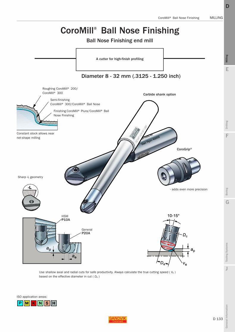
E
D 133
Mill
ing
Drilli
ng
F
Bor
ing
G
Tool
ing
Syst
ems
J
Gen
eral
Info
rmat
ion
DD
Mill
ing
CoroMill® Ball Nose Finishing MILLING
MILLING CoroMill®
Ball Nose Finishing
CoroMill® Ball Nose FinishingBall Nose Finishing end mill
A cutter for high-finish profiling
Diameter 8 - 32 mm (.3125 - 1.250 inch)
Roughing CoroMill® 200/CoroMill® 300
Semi-finishing CoroMill® 300/CoroMill® Ball Nose
Finishing CoroMill® Plura/CoroMill® Ball Nose Finishing
Constant stock allows near net-shape milling
Carbide shank option
Sharp -L geometry
HSMP10A
GeneralP20A
Use shallow axial and radial cuts for safe productivity. Always calculate the true cutting speed ( Ve ) based on the effective diameter in cut ( De )
CoroGrip®
- adds even more precision
ISO application areas:
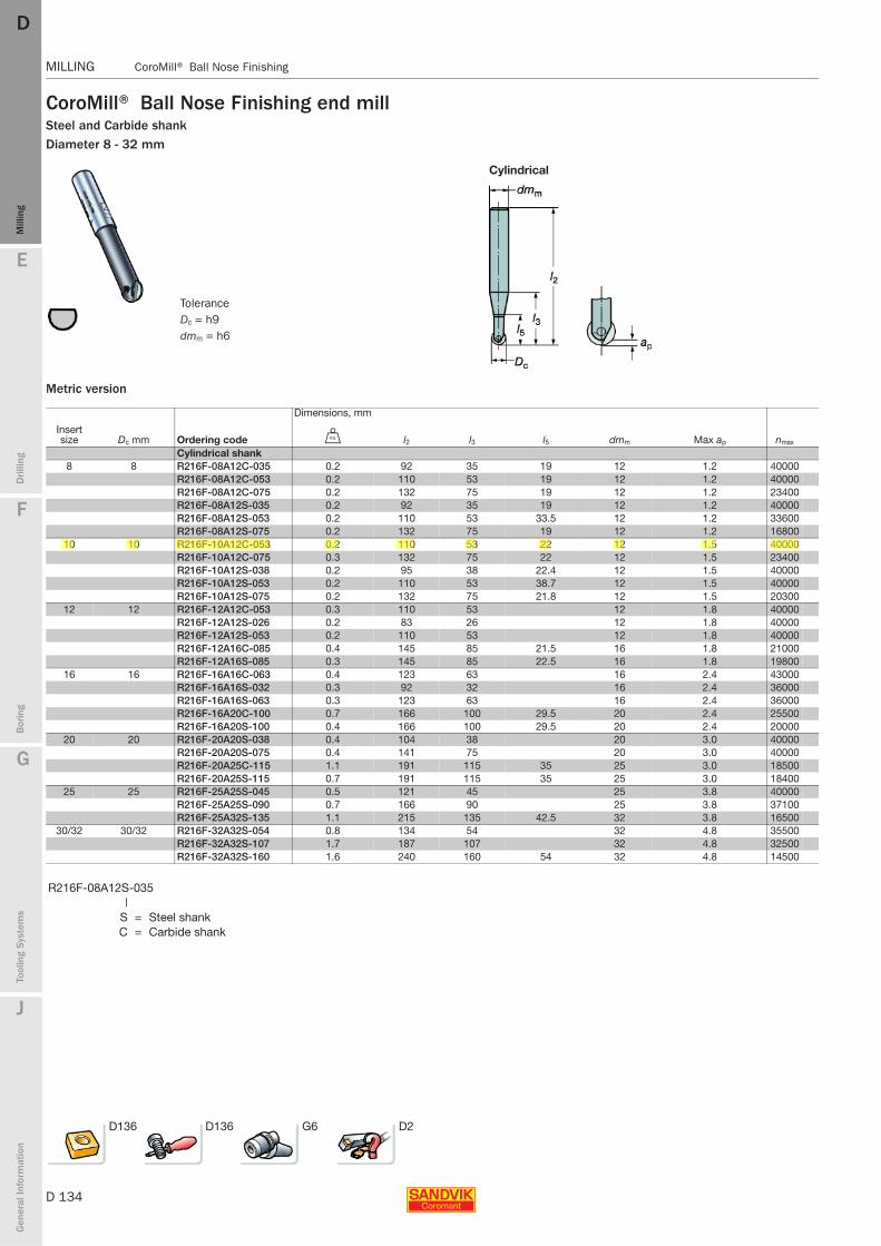
D 134
MILLING CoroMill® Ball Nose Finishing
E
Mill
ing
Drilli
ng
F
Bor
ing
G
Tool
ing
Syst
ems
J
Gen
eral
Info
rmat
ion
DDM
illin
g
MILLING CoroMill®
Ball Nose Finishing
CoroMill® Ball Nose Finishing end millSteel and Carbide shankDiameter 8 - 32 mm
Metric version
Cylindrical
Dimensions, mm
Insert size Dc mm Ordering code U l2 l3 l5 dmm Max ap nmax
Cylindrical shank8 8 R216F-08A12C-035 0.2 92 35 19 12 1.2 40000
R216F-08A12C-053 0.2 110 53 19 12 1.2 40000R216F-08A12C-075 0.2 132 75 19 12 1.2 23400R216F-08A12S-035 0.2 92 35 19 12 1.2 40000R216F-08A12S-053 0.2 110 53 33.5 12 1.2 33600R216F-08A12S-075 0.2 132 75 19 12 1.2 16800
10 10 R216F-10A12C-053 0.2 110 53 22 12 1.5 40000R216F-10A12C-075 0.3 132 75 22 12 1.5 23400R216F-10A12S-038 0.2 95 38 22.4 12 1.5 40000R216F-10A12S-053 0.2 110 53 38.7 12 1.5 40000R216F-10A12S-075 0.2 132 75 21.8 12 1.5 20300
12 12 R216F-12A12C-053 0.3 110 53 12 1.8 40000R216F-12A12S-026 0.2 83 26 12 1.8 40000R216F-12A12S-053 0.2 110 53 12 1.8 40000R216F-12A16C-085 0.4 145 85 21.5 16 1.8 21000R216F-12A16S-085 0.3 145 85 22.5 16 1.8 19800
16 16 R216F-16A16C-063 0.4 123 63 16 2.4 43000R216F-16A16S-032 0.3 92 32 16 2.4 36000R216F-16A16S-063 0.3 123 63 16 2.4 36000R216F-16A20C-100 0.7 166 100 29.5 20 2.4 25500R216F-16A20S-100 0.4 166 100 29.5 20 2.4 20000
20 20 R216F-20A20S-038 0.4 104 38 20 3.0 40000R216F-20A20S-075 0.4 141 75 20 3.0 40000R216F-20A25C-115 1.1 191 115 35 25 3.0 18500R216F-20A25S-115 0.7 191 115 35 25 3.0 18400
25 25 R216F-25A25S-045 0.5 121 45 25 3.8 40000R216F-25A25S-090 0.7 166 90 25 3.8 37100R216F-25A32S-135 1.1 215 135 42.5 32 3.8 16500
30/32 30/32 R216F-32A32S-054 0.8 134 54 32 4.8 35500R216F-32A32S-107 1.7 187 107 32 4.8 32500R216F-32A32S-160 1.6 240 160 54 32 4.8 14500
R216F-08A12S-035|
S = Steel shankC = Carbide shank
D136 D136 G6 D2
ToleranceDc = h9dmm = h6
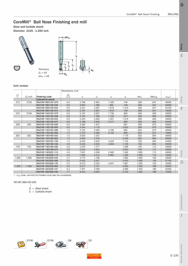
E
D 135
Mill
ing
Drilli
ng
F
Bor
ing
G
Tool
ing
Syst
ems
J
Gen
eral
Info
rmat
ion
DD
Mill
ing
CoroMill® Ball Nose Finishing MILLING
MILLING CoroMill®
Ball Nose Finishing
CoroMill® Ball Nose Finishing end millSteel and Carbide shankDiameter .3125 - 1.250 inch
Inch version
Dimensions, inch
K Dc inch Ordering code V l2 l3 l4 l5 dmm Max ap nmax1)
Cylindrical shank.312 .3126 RA216F-08O13C-075 0.9 5.196 2.952 1.429 .748 .500 .047 40000
RA216F-08O13S-035 0.9 3.622 1.398 .906 .748 .500 .047 40000RA216F-08O13S-053 0.9 4.331 2.091 1.618 1.319 .500 .047 33100RA216F-08O13S-075 0.9 5.197 2.957 1.610 .748 .500 .047 16500
.375 .3748 RA216F-10O13C-075 0.9 5.187 2.937 1.736 .850 .500 .056 40000RA216F-10O13S-038 0.9 3.732 1.508 1.102 .874 .500 .056 40000RA216F-10O13S-053 0.9 4.323 2.083 1.937 1.516 .500 .056 40000RA216F-10O13S-075 0.9 5.189 2.949 2.417 .850 .500 .056 20400
.500 .500 RA216F-13O13S-026 0.9 3.282 1.047 .961 .500 .075 40000RA216F-13O13S-053 0.9 4.344 2.110 2.022 .500 .075 40000RA216F-13O16C-085 1.5 5.722 3.360 3.189 .862 .625 .075 40000RA216F-13O16S-085 1.5 5.722 3.360 3.102 .898 .625 .075 19800
.625 .625 RA216F-16O16S-032 1.5 3.620 1.257 1.179 .625 .094 36000RA216F-16O16S-063 1.5 4.840 2.478 2.400 .625 .094 36000RA216F-16O19C-100 1.4 6.532 3.933 3.425 1.122 .750 .094 24000RA216F-16O19S-100 2.0 6.533 3.935 2.850 1.158 .750 .094 20000
.750 .750 RA216F-19O19S-038 2.0 4.076 1.477 1.396 .750 .112 40000RA216F-19O19S-075 2.0 5.532 2.934 2.853 .750 .112 40000RA216F-19O25C-115 4.9 7.501 4.509 2.460 1.362 1.000 .112 40000RA216F-19O25S-115 3.3 7.500 4.512 2.602 1.358 1.000 .112 18400
1.000 1.000 RA216F-25O25S-045 2.4 4.772 1.780 1.682 1.000 .150 40000RA216F-25O25S-090 3.3 6.543 3.551 3.453 1.000 .150 37100RA216F-25O32S-135 5.3 8.472 5.323 4.047 1.681 1.250 .150 16500
1.250 1.250 RA216F-32O32S-054 4.0 5.271 2.121 2.003 1.250 .188 35500RA216F-32O32S-107 5.3 7.357 4.208 4.089 1.250 .188 32500RA216F-32O32S-160 7.7 9.444 6.294 2.122 1.250 .188 14500
1) nmax (max. rev/min) for holders must also be considered.
R216F-08A12S-035|
S = Steel shankC = Carbide shank
D136 D136 G6 D2
ToleranceDc = h9dmm = h6
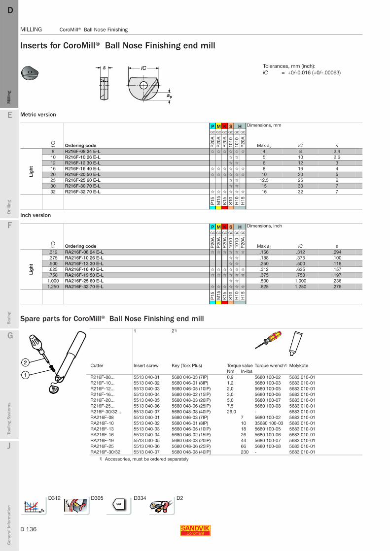
D 136
MILLING CoroMill® Ball Nose Finishing
E
Mill
ing
Drilli
ng
F
Bor
ing
G
Tool
ing
Syst
ems
J
Gen
eral
Info
rmat
ion
DDM
illin
g
MILLING CoroMill®
Ball Nose Finishing
Inserts for CoroMill® Ball Nose Finishing end mill
Metric version
Inch version
Spare parts for CoroMill® Ball Nose Finishing end mill
Tolerances, mm (inch):iC = +0/-0.016 (+0/-.00063)
P M K S H Dimensions, mm
L Ordering code
GC GC GC GC GC GC
Max ap iC s P20
AP
20A
P20
A10
1010
10P
20A
Lig
ht
8 R216F-08 24 E-L ✩ ✩ ✩ ✩ ✩ ✩ 4 8 2.410 R216F-10 26 E-L ✩ ✩ 5 10 2.612 R216F-12 30 E-L ✩ ✩ 6 12 316 R216F-16 40 E-L ✩ ✩ ✩ ✩ ✩ ✩ 8 16 420 R216F-20 50 E-L ✩ ✩ ✩ ✩ ✩ ✩ 10 20 525 R216F-25 60 E-L ✩ ✩ 12.5 25 630 R216F-30 70 E-L ✩ ✩ 15 30 732 R216F-32 70 E-L ✩ ✩ ✩ ✩ ✩ ✩ 16 32 7
P15
M15
K15
S10
H10
H15
P M K S H Dimensions, inch
L Ordering code
GC GC GC GC GC GC
Max ap iC s P20
AP
20A
P20
A10
1010
10P
20A
Lig
ht
.312 RA216F-08 24 E-L ✩ ✩ ✩ ✩ ✩ ✩ .156 .312 .094
.375 RA216F-10 26 E-L ✩ ✩ .188 .375 .100
.500 RA216F-13 30 E-L ✩ ✩ .250 .500 .118
.625 RA216F-16 40 E-L ✩ ✩ ✩ ✩ ✩ ✩ .312 .625 .157
.750 RA216F-19 50 E-L ✩ ✩ ✩ ✩ ✩ ✩ .375 .750 .1971.000 RA216F-25 60 E-L ✩ ✩ .500 1.000 .2361.250 RA216F-32 70 E-L ✩ ✩ ✩ ✩ ✩ ✩ .625 1.250 .276
P15
M15
K15
S10
H10
H15
1 21)
Cutter Insert screw Key (Torx Plus) Torque value Torque wrench1) MolykoteNm In-lbs
R216F-08... 5513 040-01 5680 046-03 (7IP) 0,9 5680 100-02 5683 010-01R216F-10... 5513 040-02 5680 046-01 (8IP) 1,2 5680 100-03 5683 010-01R216F-12... 5513 040-03 5680 046-05 (10IP) 2,0 5680 100-05 5683 010-01R216F-16... 5513 040-04 5680 046-02 (15IP) 3,0 5680 100-06 5683 010-01R216F-20... 5513 040-05 5680 048-03 (20IP) 5,0 5680 100-07 5683 010-01R216F-25... 5513 040-06 5680 048-06 (25IP) 7,5 5680 100-08 5683 010-01R216F-30/32... 5513 040-07 5680 048-08 (40IP) 26,0 - 5683 010-01RA216F-08 5513 040-01 5680 046-03 (7IP) 7 5680 100-02 5683 010-01RA216F-10 5513 040-02 5680 046-01 (8IP) 10 35680 100-03 5683 010-01RA216F-13 5513 040-03 5680 046-05 (10IP) 18 5680 100-05 5683 010-01RA216F-16 5513 040-04 5680 046-02 (15IP) 26 5680 100-06 5683 010-01RA216F-19 5513 040-05 5680 048-03 (20IP) 44 5680 100-07 5683 010-01RA216F-25 5513 040-06 5680 048-06 (25IP) 66 5680 100-08 5683 010-01RA216F-30/32 5513 040-07 5680 048-08 (40IP] 230 - 5683 010-01
1) Accessories, must be ordered separately
D312 D305 D334 D2
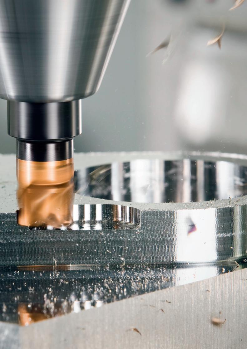
Rotating_Utfyllnadssidor.indd 3 2010-12-09 12:30:06
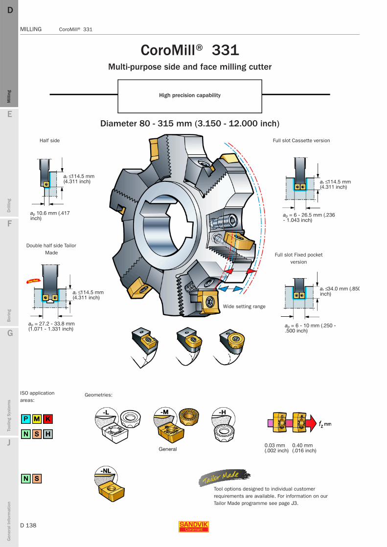
D 138
MILLING CoroMill® 331
E
Mill
ing
Drilli
ng
F
Bor
ing
G
Tool
ing
Syst
ems
J
Gen
eral
Info
rmat
ion
DDM
illin
g
MILLING CoroMill® 331
General
CoroMill® 331 Multi-purpose side and face milling cutter
High precision capability
Diameter 80 - 315 mm (3.150 - 12.000 inch)
Half side
ar ≤ 114.5 mm (4.311 inch)
ap 10.6 mm (.417 inch)
Double half side Tailor Made
ar ≤ 114.5 mm (4.311 inch)
ap = 27.2 - 33.8 mm (1.071 - 1.331 inch)
ISO application areas:
Wide setting range
Geometries:
Full slot Cassette version
ar ≤ 114.5 mm (4.311 inch)
ap = 6 - 26.5 mm (.236 - 1.043 inch)
Full slot Fixed pocket version
ar ≤ 34.0 mm (.850inch)
ap = 6 - 10 mm (.250 - .500 inch)
0.03 mm(.002 inch)
0.40 mm(.016 inch)
Tool options designed to individual customer requirements are available. For information on our Tailor Made programme see page J3.

E
D 139
Mill
ing
Drilli
ng
F
Bor
ing
G
Tool
ing
Syst
ems
J
Gen
eral
Info
rmat
ion
DD
Mill
ing
CoroMill® 331 MILLING
MILLING CoroMill® 331
Insert size and the radii available
Inserts for CoroMill® 331
Only five insert sizes needed
A comprehensive programme of standard and Tailor Made inserts for the manufacturing of all types of grooves shoulders, back faces and bores
Insert size
Max. width, mm, inch
Min. width, mm, inch
Cutter widths, mm/inch
Cutter widths, mm/inch
Groove width (ap)
Light cutting radius inserts in H tolerance for most materials
Insert size
Recommendations for full slot milling with round inserts
Max axial depth of cut (ap) = insert size (iC)
Max radial depth of cut (ae) = 1/2 iC
Note!The contact length of the cutting edge is 180°
Note: Crest of 0.02 mm (.0008 inch)
For slots deeper than iC a 0.5 mm (.020 inch)adjustment of each cassette is recommended. This will widen the groove 0.5+0.5 mm (.020+.020 inch) and reduce the contact length for each insert to 90° .
Max depth of slot (ae) > Insert size (iC)
Insert size and Min - Max width of slot
Other radii available as TailorMade
Min. width, mm, inch
Max. width, mm, inch
rε mm rε inch

D 140
MILLING CoroMill® 331
E
Mill
ing
Drilli
ng
F
Bor
ing
G
Tool
ing
Syst
ems
J
Gen
eral
Info
rmat
ion
DDM
illin
g
MILLING CoroMill® 331
Full side and face millDiameter 80 – 315 mmPositive rake
Bore with keyway*)
N331.32 type shown
Cassettes, see page D165. *) Number of keyways, see page D157.
Width 6.0-12.0 mml1 = programming length
Metric version
Slot width
Mountingap mm Dc mm Dc mm zn ap rε5) ap zn 0.2-1.54 rε6)
Bore with keyway
Insert size
80 6 N331.32-080S27CM *xx.xx* N331.32-080S27CMx *xx.xx* – 04100 8 N331.32-100S32CM *xx.xx* N331.32-100S32CMx *xx.xx* – 04125 10 N331.32-125S40CM *xx.xx* N331.32-125S40CMx *xx.xx* – 04160 12 N331.32-160S40CM *xx.xx* N331.32-160S40CMx *xx.xx* – 04200 16 N331.32-200S50CM *xx.xx* N331.32-200S50CMx *xx.xx* – 04
6.0– 8.0 Arbor 80 6 R331.32-080Q27CM *xx.xx* R331.32-080Q27CMx *xx.xx* – 04100 8 R331.32-100Q27CM *xx.xx* R331.32-100Q27CMx *xx.xx* – 04125 10 R331.32-125Q32CM *xx.xx* R331.32-125Q32CMx *xx.xx* – 04160 12 R331.32-160Q40CM *xx.xx* R331.32-160Q40CMx *xx.xx* – 04200 16 R331.32-200Q40CM *xx.xx* R331.32-200Q40CMx *xx.xx* – 04
Cylindrical 80 6 R331.32-080A32CM *xx.xx* - *xx.xx* – 04100 8 R331.32-100A42CM *xx.xx* - *xx.xx* – 04
Bore with keyway
80 6 N331.32-080S27DM *xx.xx* N331.32-080S27DMx *xx.xx* – 05100 8 N331.32-100S32DM *xx.xx* N331.32-100S32DMx *xx.xx* – 05125 10 N331.32-125S40DM *xx.xx* N331.32-125S40DMx *xx.xx* – 05160 12 N331.32-160S40DM *xx.xx* N331.32-160S40DMx *xx.xx* – 05200 16 N331.32-200S50DM *xx.xx* N331.32-200S50DMx *xx.xx* – 05
7.9–10.0 Arbor 80 6 R331.32-080Q27DM *xx.xx* R331.32-080Q27DMx *xx.xx* – 05100 8 R331.32-100Q27DM *xx.xx* R331.32-100Q27DMx *xx.xx* – 05125 10 R331.32-125Q32DM *xx.xx* R331.32-125Q32DMx *xx.xx* – 05160 12 R331.32-160Q40DM *xx.xx* R331.32-160Q40DMx *xx.xx* – 05200 16 R331.32-200Q40DM *xx.xx* R331.32-200Q40DMx *xx.xx* – 05
Cylindrical 80 6 R331.32-080A32DM *xx.xx* - *xx.xx* – 05100 8 R331.32-100A42DM *xx.xx* - *xx.xx* – 05
Bore with keyway
80 6 N331.32-080S27EM *xx.xx* N331.32-080S27EMx *xx.xx* 82 6 N331.32-082S27EMQ1) 08100 8 N331.32-100S32EM *xx.xx* N331.32-100S32EMx *xx.xx* 102 8 N331.32-102S32EMQ1) 08125 10 N331.32-125S40EM *xx.xx* N331.32-125S40EMx *xx.xx* 127 10 N331.32-127S40EMQ1) 08160 12 N331.32-160S40EM *xx.xx* N331.32-160S40EMx *xx.xx* 162 12 N331.32-162S40EMQ1) 08200 16 N331.32-200S50EM *xx.xx* N331.32-200S50EMx *xx.xx* 202 16 N331.32-202S50EMQ1) 08
10.0–12.0 Arbor 80 6 R331.32-080Q27EM *xx.xx* R331.32-080Q27EMx *xx.xx* 82 6 R331.32-082Q27EMQ1) 08100 8 R331.32-100Q27EM *xx.xx* R331.32-100Q27EMx *xx.xx* 102 8 R331.32-102Q27EMQ1) 08125 10 R331.32-125Q32EM *xx.xx* R331.32-125Q32EMx *xx.xx* 127 10 R331.32-127Q32EMQ1) 08160 12 R331.32-160Q40EM *xx.xx* R331.32-160Q40EMx *xx.xx* 162 12 R331.32-162Q40EMQ1) 08200 16 R331.32-200Q40EM *xx.xx* R331.32-200Q40EMx *xx.xx* 202 16 R331.32-202Q40EMQ1) 08
Cylindrical 80 6 R331.32-080A32EM *xx.xx* - *xx.xx* – 08100 8 R331.32-100A42EM *xx.xx* - *xx.xx* – 08
1) Slot width, ap = insert size*xx.xx* = in the ordering code indicates the width ap in mm to two decimal places.5) x = in the ordering code indicates the insert radius range (rε) A, B, D, E or Q.6) For insert radius range 0.2-1.54, no prefix is read at x in the ordering code. Example: 2 pieces N331.32-080S27CM.
D160 D165 G6 D2 J3

E
D 141
Mill
ing
Drilli
ng
F
Bor
ing
G
Tool
ing
Syst
ems
J
Gen
eral
Info
rmat
ion
DD
Mill
ing
CoroMill® 331 MILLING
MILLING CoroMill® 331
Full side and face mill
Arbor CylindricalEffective number of teeth:
zc = zn 2
R331.32 type shown
Effective number of teeth:
zc = zn
ISO A ISO B ISO C l1 = programming length
For insert radius range, rε5) Dimensions, mm
A B D E Q l13)
1.55-2.60 2.61-3.50 4.51-5.50 5.51-6.50 Round U ar dmm ISO E BKW min.–max l2 l3 asp D4 dhc nmax4)
Insert size Insert size Insert size Insert size Insert size
04 0.3 19.5 27 14 7 10–11 – – 4.4 – – 19 30004 0.8 25.5 32 14 8 10–11 – – 4.4 – – 17 10004 0.8 34.0 40 14 10 10–11 – – 4.4 – – 15 10004 1.1 51.5 40 14 10 10–11 – – 4.4 – – 13 20004 2.1 64.5 50 14 12 10–11 – – 4.4 – – 11 70004 0.8 20 27 A – 12.4 63–64 – 40 4.4 54.0 – 19 30004 1.6 22 27 A – 12.4 63–64 – – 4.4 54.0 – 17 10004 1.8 29.5 32 B – 14.4 63–64 – – 4.4 64.0 – 15 10004 2.6 41 40 B – 16.4 63–64 – – 4.4 76.0 – 13 20004 6.7 51 40 C – 16.4 63–64 – – 4.4 96.0 66.7 11 700
1 23 32 – – – 132 – 4.4 – – 19 3001 28 42 – – – 152 – 4.4 – – 17 100
05 05 0.3 19.5 27 16 7 12–13 – – 5.6 – – 15 00005 05 0.5 25.5 32 16 8 12–13 – – 5.6 – – 13 20005 05 0.8 34.0 40 16 10 12–13 – – 5.6 – – 11 70005 05 1.3 51.5 40 16 10 12–13 – – 5.6 – – 10 20005 05 2.1 64.5 50 16 12 12–13 – – 5.6 – – 9 10005 05 0.8 20 27 A – 12.4 63–64 – 40 5.6 54.0 – 15 00005 05 1.2 22 27 A – 12.4 63–64 – – 5.6 54.0 – 13 20005 05 1.8 29.5 32 B – 14.4 63–64 – – 5.6 64.0 – 11 70005 05 2.6 41 40 B – 16.4 63–64 – – 5.6 76.0 – 10 20005 05 7 51 40 C – 16.4 63–64 – – 5.6 96.0 66.7 9 100
1 23 32 – – – 132 – 6.2 – – 15 0001.9 28 42 – – – 152 – 6.2 – – 13 200
08 08 10 0.3 19.55) 27 16 7 13–14 – – 6.2 – – 18 10008 08 10 0.5 25.55) 32 16 8 13–14 – – 6.2 – – 15 90008 08 10 0.8 34.05) 40 16 10 13–14 – – 6.2 – – 14 10008 08 10 1.3 51.55) 40 16 10 13–14 – – 6.2 – – 12 40008 08 10 2.1 64.55) 50 16 12 13–14 – – 6.2 – – 11 00008 08 10 1.1 205) 27 A – 12.4 63–64 – 40 6.2 54.0 – 18 10008 08 10 1.7 225) 27 A – 12.4 63–64 – – 6.2 54.0 – 15 90008 08 10 1.8 29.55) 32 B – 14.4 63–64 – – 6.2 64.0 – 14 10008 08 10 2.6 415) 40 B – 16.4 63–64 – – 6.2 76.0 – 12 40008 08 10 4.3 515) 40 C – 16.4 63–64 – – 6.2 96.0 66.7 11 000
1 23 32 – – – 132 – 6.2 – – 18 1001.9 28 42 – – – 152 – 6.2 – – 15 900
3) The programming length, l1, depends on cutter width setting.
Ordering example for a size 80 cutter pre-set to 6.26 mm:2 pieces N331.32-080S27CM*06.26*
4) nmax (max. rev/min) for holders must also be considered.
Orders without width specifications are delivered set to minimum dimensions.Ordering example: 2 pieces N331.32-080S27CM
5) Cutters with round inserts = ar + 1mm
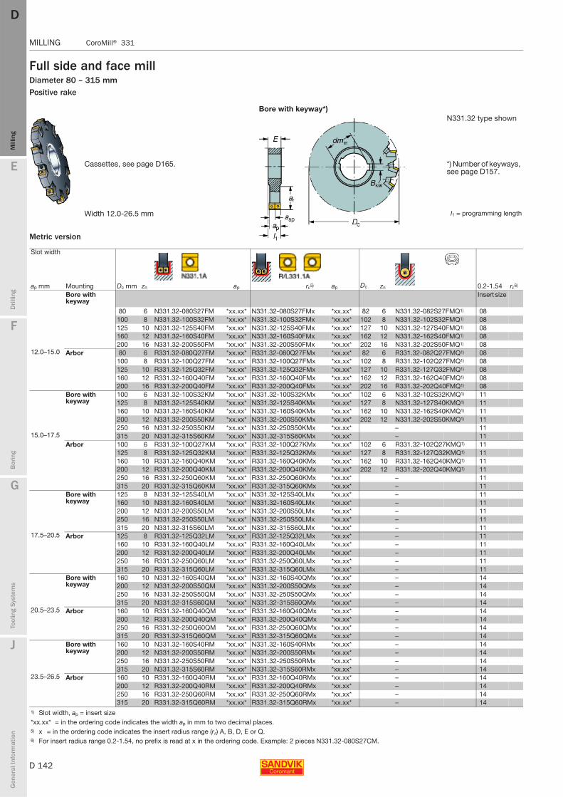
D 142
MILLING CoroMill® 331
E
Mill
ing
Drilli
ng
F
Bor
ing
G
Tool
ing
Syst
ems
J
Gen
eral
Info
rmat
ion
DDM
illin
g
MILLING CoroMill® 331
Full side and face millDiameter 80 – 315 mmPositive rake
Metric version
Bore with keyway*)N331.32 type shown
Cassettes, see page D165. *) Number of keyways, see page D157.
Width 12.0-26.5 mm l1 = programming length
Slot width
Mountingap mm Dc mm zn ap rε5) ap Dc zn 0.2-1.54 rε6)
Bore with keyway
Insert size
80 6 N331.32-080S27FM *xx.xx* N331.32-080S27FMx *xx.xx* 82 6 N331.32-082S27FMQ1) 08100 8 N331.32-100S32FM *xx.xx* N331.32-100S32FMx *xx.xx* 102 8 N331.32-102S32FMQ1) 08125 10 N331.32-125S40FM *xx.xx* N331.32-125S40FMx *xx.xx* 127 10 N331.32-127S40FMQ1) 08160 12 N331.32-160S40FM *xx.xx* N331.32-160S40FMx *xx.xx* 162 12 N331.32-162S40FMQ1) 08200 16 N331.32-200S50FM *xx.xx* N331.32-200S50FMx *xx.xx* 202 16 N331.32-202S50FMQ1) 08
12.0–15.0 Arbor 80 6 R331.32-080Q27FM *xx.xx* R331.32-080Q27FMx *xx.xx* 82 6 R331.32-082Q27FMQ1) 08100 8 R331.32-100Q27FM *xx.xx* R331.32-100Q27FMx *xx.xx* 102 8 R331.32-102Q27FMQ1) 08125 10 R331.32-125Q32FM *xx.xx* R331.32-125Q32FMx *xx.xx* 127 10 R331.32-127Q32FMQ1) 08160 12 R331.32-160Q40FM *xx.xx* R331.32-160Q40FMx *xx.xx* 162 12 R331.32-162Q40FMQ1) 08200 16 R331.32-200Q40FM *xx.xx* R331.32-200Q40FMx *xx.xx* 202 16 R331.32-202Q40FMQ1) 08
Bore with keyway
100 6 N331.32-100S32KM *xx.xx* N331.32-100S32KMx *xx.xx* 102 6 N331.32-102S32KMQ1) 11125 8 N331.32-125S40KM *xx.xx* N331.32-125S40KMx *xx.xx* 127 8 N331.32-127S40KMQ1) 11160 10 N331.32-160S40KM *xx.xx* N331.32-160S40KMx *xx.xx* 162 10 N331.32-162S40KMQ1) 11200 12 N331.32-200S50KM *xx.xx* N331.32-200S50KMx *xx.xx* 202 12 N331.32-202S50KMQ1) 11250 16 N331.32-250S50KM *xx.xx* N331.32-250S50KMx *xx.xx* – 11
15.0–17.5 315 20 N331.32-315S60KM *xx.xx* N331.32-315S60KMx *xx.xx* – 11Arbor 100 6 R331.32-100Q27KM *xx.xx* R331.32-100Q27KMx *xx.xx* 102 6 R331.32-102Q27KMQ1) 11
125 8 R331.32-125Q32KM *xx.xx* R331.32-125Q32KMx *xx.xx* 127 8 R331.32-127Q32KMQ1) 11160 10 R331.32-160Q40KM *xx.xx* R331.32-160Q40KMx *xx.xx* 162 10 R331.32-162Q40KMQ1) 11200 12 R331.32-200Q40KM *xx.xx* R331.32-200Q40KMx *xx.xx* 202 12 R331.32-202Q40KMQ1) 11250 16 R331.32-250Q60KM *xx.xx* R331.32-250Q60KMx *xx.xx* – 11315 20 R331.32-315Q60KM *xx.xx* R331.32-315Q60KMx *xx.xx* – 11
Bore with keyway
125 8 N331.32-125S40LM *xx.xx* N331.32-125S40LMx *xx.xx* – 11160 10 N331.32-160S40LM *xx.xx* N331.32-160S40LMx *xx.xx* – 11200 12 N331.32-200S50LM *xx.xx* N331.32-200S50LMx *xx.xx* – 11250 16 N331.32-250S50LM *xx.xx* N331.32-250S50LMx *xx.xx* – 11315 20 N331.32-315S60LM *xx.xx* N331.32-315S60LMx *xx.xx* – 11
17.5–20.5 Arbor 125 8 R331.32-125Q32LM *xx.xx* R331.32-125Q32LMx *xx.xx* – 11160 10 R331.32-160Q40LM *xx.xx* R331.32-160Q40LMx *xx.xx* – 11200 12 R331.32-200Q40LM *xx.xx* R331.32-200Q40LMx *xx.xx* – 11250 16 R331.32-250Q60LM *xx.xx* R331.32-250Q60LMx *xx.xx* – 11315 20 R331.32-315Q60LM *xx.xx* R331.32-315Q60LMx *xx.xx* – 11
Bore with keyway
160 10 N331.32-160S40QM *xx.xx* N331.32-160S40QMx *xx.xx* – 14200 12 N331.32-200S50QM *xx.xx* N331.32-200S50QMx *xx.xx* – 14250 16 N331.32-250S50QM *xx.xx* N331.32-250S50QMx *xx.xx* – 14315 20 N331.32-315S60QM *xx.xx* N331.32-315S60QMx *xx.xx* – 14
20.5–23.5 Arbor 160 10 R331.32-160Q40QM *xx.xx* R331.32-160Q40QMx *xx.xx* – 14200 12 R331.32-200Q40QM *xx.xx* R331.32-200Q40QMx *xx.xx* – 14250 16 R331.32-250Q60QM *xx.xx* R331.32-250Q60QMx *xx.xx* – 14315 20 R331.32-315Q60QM *xx.xx* R331.32-315Q60QMx *xx.xx* – 14
Bore with keyway
160 10 N331.32-160S40RM *xx.xx* N331.32-160S40RMx *xx.xx* – 14200 12 N331.32-200S50RM *xx.xx* N331.32-200S50RMx *xx.xx* – 14250 16 N331.32-250S50RM *xx.xx* N331.32-250S50RMx *xx.xx* – 14315 20 N331.32-315S60RM *xx.xx* N331.32-315S60RMx *xx.xx* – 14
23.5–26.5 Arbor 160 10 R331.32-160Q40RM *xx.xx* R331.32-160Q40RMx *xx.xx* – 14200 12 R331.32-200Q40RM *xx.xx* R331.32-200Q40RMx *xx.xx* – 14250 16 R331.32-250Q60RM *xx.xx* R331.32-250Q60RMx *xx.xx* – 14315 20 R331.32-315Q60RM *xx.xx* R331.32-315Q60RMx *xx.xx* – 14
1) Slot width, ap = insert size*xx.xx* = in the ordering code indicates the width ap in mm to two decimal places.5) x = in the ordering code indicates the insert radius range (rε) A, B, D, E or Q.6) For insert radius range 0.2-1.54, no prefix is read at x in the ordering code. Example: 2 pieces N331.32-080S27CM.
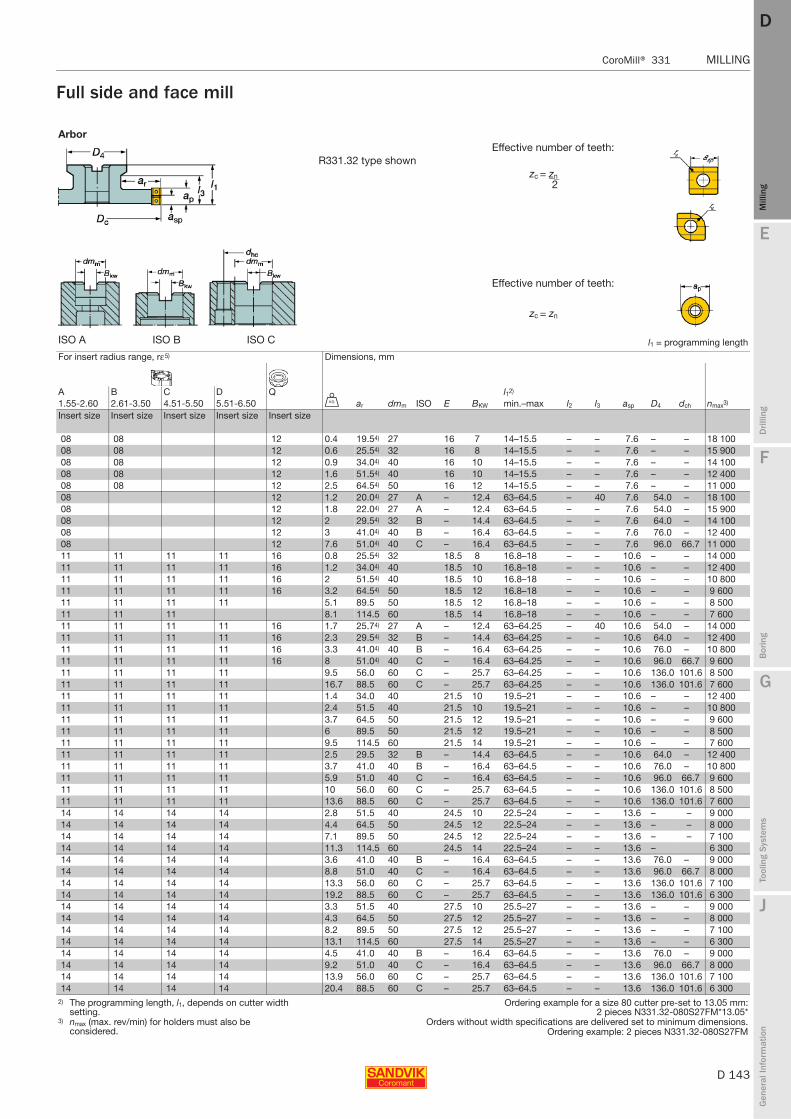
E
D 143
Mill
ing
Drilli
ng
F
Bor
ing
G
Tool
ing
Syst
ems
J
Gen
eral
Info
rmat
ion
DD
Mill
ing
CoroMill® 331 MILLING
MILLING CoroMill® 331
Full side and face mill
Arbor
R331.32 type shownEffective number of teeth:
zc = zn 2
Effective number of teeth:
zc = zn
ISO A ISO B ISO C l1 = programming length
For insert radius range, rε5) Dimensions, mm
A B C D Q l12)
1.55-2.60 2.61-3.50 4.51-5.50 5.51-6.50 U ar dmm ISO E BKW min.–max l2 l3 asp D4 dch nmax3)
Insert size Insert size Insert size Insert size Insert size
08 08 12 0.4 19.54) 27 16 7 14–15.5 – – 7.6 – – 18 10008 08 12 0.6 25.54) 32 16 8 14–15.5 – – 7.6 – – 15 90008 08 12 0.9 34.04) 40 16 10 14–15.5 – – 7.6 – – 14 10008 08 12 1.6 51.54) 40 16 10 14–15.5 – – 7.6 – – 12 40008 08 12 2.5 64.54) 50 16 12 14–15.5 – – 7.6 – – 11 00008 12 1.2 20.04) 27 A – 12.4 63–64.5 – 40 7.6 54.0 – 18 10008 12 1.8 22.04) 27 A – 12.4 63–64.5 – – 7.6 54.0 – 15 90008 12 2 29.54) 32 B – 14.4 63–64.5 – – 7.6 64.0 – 14 10008 12 3 41.04) 40 B – 16.4 63–64.5 – – 7.6 76.0 – 12 40008 12 7.6 51.04) 40 C – 16.4 63–64.5 – – 7.6 96.0 66.7 11 00011 11 11 11 16 0.8 25.54) 32 18.5 8 16.8–18 – – 10.6 – – 14 00011 11 11 11 16 1.2 34.04) 40 18.5 10 16.8–18 – – 10.6 – – 12 40011 11 11 11 16 2 51.54) 40 18.5 10 16.8–18 – – 10.6 – – 10 80011 11 11 11 16 3.2 64.54) 50 18.5 12 16.8–18 – – 10.6 – – 9 60011 11 11 11 5.1 89.5 50 18.5 12 16.8–18 – – 10.6 – – 8 50011 11 11 8.1 114.5 60 18.5 14 16.8–18 – – 10.6 – – 7 60011 11 11 11 16 1.7 25.74) 27 A – 12.4 63–64.25 – 40 10.6 54.0 – 14 00011 11 11 11 16 2.3 29.54) 32 B – 14.4 63–64.25 – – 10.6 64.0 – 12 40011 11 11 11 16 3.3 41.04) 40 B – 16.4 63–64.25 – – 10.6 76.0 – 10 80011 11 11 11 16 8 51.04) 40 C – 16.4 63–64.25 – – 10.6 96.0 66.7 9 60011 11 11 11 9.5 56.0 60 C – 25.7 63–64.25 – – 10.6 136.0 101.6 8 50011 11 11 11 16.7 88.5 60 C – 25.7 63–64.25 – – 10.6 136.0 101.6 7 60011 11 11 11 1.4 34.0 40 21.5 10 19.5–21 – – 10.6 – – 12 40011 11 11 11 2.4 51.5 40 21.5 10 19.5–21 – – 10.6 – – 10 80011 11 11 11 3.7 64.5 50 21.5 12 19.5–21 – – 10.6 – – 9 60011 11 11 11 6 89.5 50 21.5 12 19.5–21 – – 10.6 – – 8 50011 11 11 11 9.5 114.5 60 21.5 14 19.5–21 – – 10.6 – – 7 60011 11 11 11 2.5 29.5 32 B – 14.4 63–64.5 – – 10.6 64.0 – 12 40011 11 11 11 3.7 41.0 40 B – 16.4 63–64.5 – – 10.6 76.0 – 10 80011 11 11 11 5.9 51.0 40 C – 16.4 63–64.5 – – 10.6 96.0 66.7 9 60011 11 11 11 10 56.0 60 C – 25.7 63–64.5 – – 10.6 136.0 101.6 8 50011 11 11 11 13.6 88.5 60 C – 25.7 63–64.5 – – 10.6 136.0 101.6 7 60014 14 14 14 2.8 51.5 40 24.5 10 22.5–24 – – 13.6 – – 9 00014 14 14 14 4.4 64.5 50 24.5 12 22.5–24 – – 13.6 – – 8 00014 14 14 14 7.1 89.5 50 24.5 12 22.5–24 – – 13.6 – – 7 10014 14 14 14 11.3 114.5 60 24.5 14 22.5–24 – – 13.6 – 6 30014 14 14 14 3.6 41.0 40 B – 16.4 63–64.5 – – 13.6 76.0 – 9 00014 14 14 14 8.8 51.0 40 C – 16.4 63–64.5 – – 13.6 96.0 66.7 8 00014 14 14 14 13.3 56.0 60 C – 25.7 63–64.5 – – 13.6 136.0 101.6 7 10014 14 14 14 19.2 88.5 60 C – 25.7 63–64.5 – – 13.6 136.0 101.6 6 30014 14 14 14 3.3 51.5 40 27.5 10 25.5–27 – – 13.6 – – 9 00014 14 14 14 4.3 64.5 50 27.5 12 25.5–27 – – 13.6 – – 8 00014 14 14 14 8.2 89.5 50 27.5 12 25.5–27 – – 13.6 – – 7 10014 14 14 14 13.1 114.5 60 27.5 14 25.5–27 – – 13.6 – – 6 30014 14 14 14 4.5 41.0 40 B – 16.4 63–64.5 – – 13.6 76.0 – 9 00014 14 14 14 9.2 51.0 40 C – 16.4 63–64.5 – – 13.6 96.0 66.7 8 00014 14 14 14 13.9 56.0 60 C – 25.7 63–64.5 – – 13.6 136.0 101.6 7 10014 14 14 14 20.4 88.5 60 C – 25.7 63–64.5 – – 13.6 136.0 101.6 6 300
2) The programming length, l1, depends on cutter width setting.
Ordering example for a size 80 cutter pre-set to 13.05 mm:2 pieces N331.32-080S27FM*13.05*
3) nmax (max. rev/min) for holders must also be considered.
Orders without width specifications are delivered set to minimum dimensions.Ordering example: 2 pieces N331.32-080S27FM
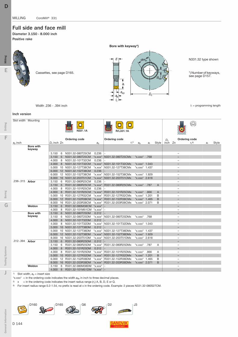
D 144
MILLING CoroMill® 331
E
Mill
ing
Drilli
ng
F
Bor
ing
G
Tool
ing
Syst
ems
J
Gen
eral
Info
rmat
ion
DDM
illin
g
MILLING CoroMill® 331
Full side and face millDiameter 3.150 - 8.000 inchPositive rake
Bore with keyway*)
N331.32 type shown
Cassettes, see page D165. *) Number of keyways, see page D157.
Width .236 - .394 inch l1 = programming length
Inch version
Slot width Mounting
ap inch Dc inchOrdering code Ordering code Dc
inchOrdering code
Zn ap rε5 ap ar Style Zn rε6) ar StyleBore with keyway
3.150 6 N331.32-080T25CM 0.236 - –3.150 6 N331.32-080T25CM *x.xxx* N331.32-080T25CMx *x.xxx* .768 –4.000 8 N331.32-101T32CM 0.236 - –4.000 8 N331.32-101T32CM *x.xxx* N331.32-101T32CMx *x.xxx* 1.043 –5.000 10 N331.32-127T38CM *x.xxx* N331.32-127T38CMx *x.xxx* 1.437 –6.000 12 N331.32-152T38CM 0.236 - –6.000 12 N331.32-152T38CM *x.xxx* N331.32-152T38CMx *x.xxx* 1.929 –8.000 16 N331.32-203T51CM *x.xxx* N331.32-203T51CMx *x.xxx* 2.618 –
.236-.315 Arbor 3.150 6 R331.32-080R25CM 0.236 - –3.150 6 R331.32-080R25CM *x.xxx* R331.32-080R25CMx *x.xxx* .787 A –4.000 8 R331.32-101R25CM 0.236 - –4.000 8 R331.32-101R25CM *x.xxx* R331.32-101R25CMx *x.xxx* .866 A –5.000 10 R331.32-127R32CM *x.xxx* R331.32-127R32CMx *x.xxx* 1.201 B –6.000 12 R331.32-152R38CM *x.xxx* R331.32-152R38CMx *x.xxx* 1.465 B –8.000 16 R331.32-203R38CM *x.xxx* R331.32-203R38CMx *x.xxx* 2.071 B –
Weldon 3.150 6 R331.32-080M38CM *x.xxx* - –4.000 8 R331.32-101M51CM *x.xxx* - –
Bore with keyway
3.150 6 N331.32-080T25DM 0.312 - –3.150 6 N331.32-080T25DM *x.xxx* N331.32-080T25DMx *x.xxx* .768 –4.000 8 N331.32-101T32DM 0.312 - –4.000 8 N331.32-101T32DM *x.xxx* N331.32-101T32DMx *x.xxx* 1.043 –5.000 10 N331.32-127T38DM 0.312 - –5.000 10 N331.32-127T38DM *x.xxx* N331.32-127T38DMx *x.xxx* 1.437 –6.000 12 N331.32-152T38DM *x.xxx* N331.32-152T38DMx *x.xxx* 1.929 –8.000 16 N331.32-203T51DM *x.xxx* N331.32-203T51DMx *x.xxx* 2.618 –
.312-.394 Arbor 3.150 6 R331.32-080R25DM 0.312 - –3.150 6 R331.32-080R25DM *x.xxx* R331.32-080R25DMx *x.xxx* .787 A –4.000 8 R331.32-101R25DM 0.312 - –4.000 8 R331.32-101R25DM *x.xxx* R331.32-101R25DMx *x.xxx* .866 A –5.000 10 R331.32-127R32DM *x.xxx* R331.32-127R32DMx *x.xxx* 1.201 B –6.000 12 R331.32-152R38DM *x.xxx* R331.32-152R38DMx *x.xxx* 1.465 B –8.000 16 R331.32-203R38DM *x.xxx* R331.32-203R38DMx *x.xxx* 2.071 B –
Weldon 3.150 6 R331.32-080M38DM *x.xxx* - –4.000 8 R331.32-101M51DM *x.xxx* - –
1) Slot width, ap = insert size*x.xxx* = in the ordering code indicates the width aBp in inch to three decimal places.5) x = in the ordering code indicates the insert radius range (rε) A, B, D, E or Q.6) For insert radius range 0.2-1.54, no prefix is read at x in the ordering code. Example: 2 pieces N331.32-080S27CM.
D160 D165 G6 D2 J3
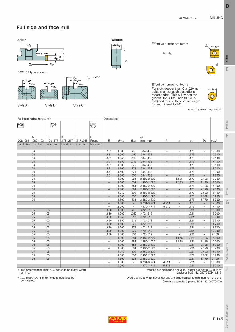
E
D 145
Mill
ing
Drilli
ng
F
Bor
ing
G
Tool
ing
Syst
ems
J
Gen
eral
Info
rmat
ion
DD
Mill
ing
CoroMill® 331 MILLING
MILLING CoroMill® 331
Full side and face mill
Arbor WeldonEffective number of teeth:
zc = zn 2
R331.32 type shown
Effective number of teeth:For slots deeper than iC a .020 inch adjustment of each cassette is recomended. This will widen the groove .020+.020 inch (0.5+0.5 mm) and reduce the contact length for each insert to 90° .Style A Style B Style C
l1 = programming length
For insert radius range, rε5) Dimensions
A B D E Q l12)
.008-.061 .060-.102 .103-.177 .178-.217 .217-.256 Round E dmm BKW min.–max l2 l3 asp D4 nmax3)
Insert size Insert size Insert size Insert size Insert size Insert size
04 .551 1.000 .250 .394-.433 – – .173 – 19 30004 .551 1.000 .250 .394-.433 – – .173 – 19 30004 .551 1.250 .312 .394-.433 – – .173 – 17 10004 .551 1.250 .312 .394-.433 – – .173 – 17 10004 .551 1.500 .375 .394-.433 – – .173 – 15 10004 .551 1.500 .375 .394-.433 – – .173 – 13 20004 .551 1.500 .375 .394-.433 – – .173 – 13 20004 .551 2.000 .500 .394-.433 – – .173 – 11 70004 – 1.000 .384 2.480-2.520 – 1.525 .173 2.126 19 30004 – 1.000 .384 2.480-2.520 – 1.525 .173 2.126 19 30004 – 1.000 .384 2.480-2.520 – – .173 2.126 17 10004 – 1.000 .384 2.480-2.520 – – .173 2.126 17 10004 – 1.250 .509 2.480-2.520 – – .173 2.522 15 10004 – 1.500 .633 2.480-2.520 – – .173 2.992 13 20004 – 1.500 .633 2.480-2.520 – – .173 3.779 11 700
– 1.500 – 3.734-3.774 4.921 – .173 – 19 300– 2.000 – 3.670-3.711 5.575 – .173 – 17 100
05 05 .630 1.000 .250 .472-.512 – – .221 – 15 00005 05 .630 1.000 .250 .472-.512 – – .221 – 15 00005 05 .630 1.250 .312 .472-.512 – – .221 – 13 20005 05 .630 1.250 .312 .472-.512 – – .221 – 13 20005 05 .630 1.500 .375 .472-.512 – – .221 – 11 70005 05 .630 1.500 .375 .472-.512 – – .221 – 11 70005 05 .630 1.500 .375 .472-.512 – – .221 – 10 20005 05 .630 2.000 .500 .472-.512 – – .221 – 9 10005 05 – 1.000 .384 2.480-2.520 – 1.575 .221 2.126 15 00005 05 – 1.000 .384 2.480-2.520 – 1.575 .221 2.126 15 00005 05 – 1.000 .384 2.480-2.520 – – .221 2.126 13 20005 05 – 1.000 .384 2.480-2.520 – – .221 2.126 13 20005 05 – 1.250 .509 2.480-2.520 – – .221 2.522 11 70005 05 – 1.500 .633 2.480-2.520 – – .221 2.992 10 20005 05 – 1.500 .633 2.480-2.520 – – .221 3.779 9 100
– 1.500 – 3.734-3.774 4.921 – .221 – 15 000– 2.000 – 3.670-3.711 5.575 – .221 – 13 200
2) The programming length, l1, depends on cutter width setting.
Ordering example for a size 3.150 cutter pre-set to 0.315 inch:2 pieces N331.32-080T25CM*0.315*
3) nmax (max. rev/min) for holders must also be considered.
Orders without width specifications are delivered set to minimum dimensions.Ordering example: 2 pieces N331.32-080T25CM
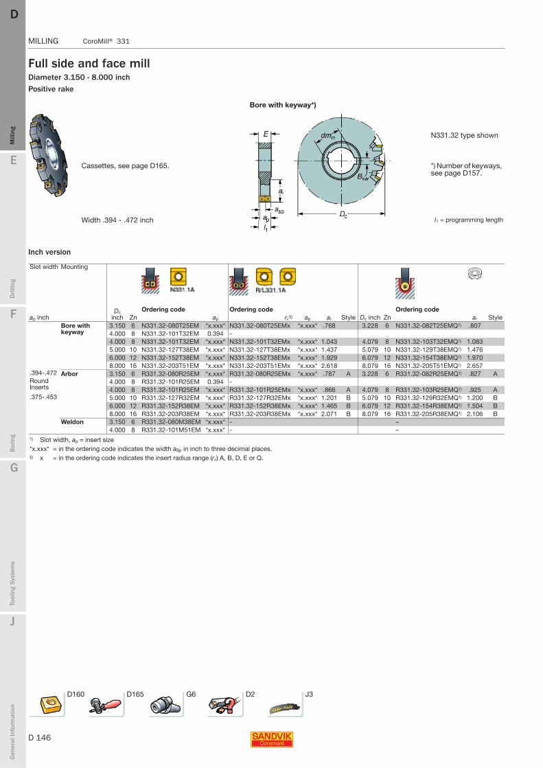
D 146
MILLING CoroMill® 331
E
Mill
ing
Drilli
ng
F
Bor
ing
G
Tool
ing
Syst
ems
J
Gen
eral
Info
rmat
ion
DDM
illin
g
MILLING CoroMill® 331
Full side and face millDiameter 3.150 - 8.000 inchPositive rake
Bore with keyway*)
N331.32 type shown
Cassettes, see page D165. *) Number of keyways, see page D157.
Width .394 - .472 inch l1 = programming length
Inch version
Slot width Mounting
ap inchDc
inchOrdering code Ordering code
Dc inchOrdering code
Zn ap rε5) ap ar Style Zn ar StyleBore with keyway
3.150 6 N331.32-080T25EM *x.xxx* N331.32-080T25EMx *x.xxx* .768 3.228 6 N331.32-082T25EMQ1) .8074.000 8 N331.32-101T32EM 0.394 -4.000 8 N331.32-101T32EM *x.xxx* N331.32-101T32EMx *x.xxx* 1.043 4.079 8 N331.32-103T32EMQ1) 1.0835.000 10 N331.32-127T38EM *x.xxx* N331.32-127T38EMx *x.xxx* 1.437 5.079 10 N331.32-129T38EMQ1) 1.4766.000 12 N331.32-152T38EM *x.xxx* N331.32-152T38EMx *x.xxx* 1.929 6.079 12 N331.32-154T38EMQ1) 1.9708.000 16 N331.32-203T51EM *x.xxx* N331.32-203T51EMx *x.xxx* 2.618 8.079 16 N331.32-205T51EMQ1) 2.657
.394-.472 Arbor 3.150 6 R331.32-080R25EM *x.xxx* R331.32-080R25EMx *x.xxx* .787 A 3.228 6 R331.32-082R25EMQ1) .827 ARound Inserts
4.000 8 R331.32-101R25EM 0.394 -4.000 8 R331.32-101R25EM *x.xxx* R331.32-101R25EMx *x.xxx* .866 A 4.079 8 R331.32-103R25EMQ1) .925 A
.375-.453 5.000 10 R331.32-127R32EM *x.xxx* R331.32-127R32EMx *x.xxx* 1.201 B 5.079 10 R331.32-129R32EMQ1) 1.200 B6.000 12 R331.32-152R38EM *x.xxx* R331.32-152R38EMx *x.xxx* 1.465 B 6.079 12 R331.32-154R38EMQ1) 1.504 B8.000 16 R331.32-203R38EM *x.xxx* R331.32-203R38EMx *x.xxx* 2.071 B 8.079 16 R331.32-205R38EMQ1) 2.106 B
Weldon 3.150 6 R331.32-080M38EM *x.xxx* - –4.000 8 R331.32-101M51EM *x.xxx* - –
1) Slot width, ap = insert size*x.xxx* = in the ordering code indicates the width aBp in inch to three decimal places.5) x = in the ordering code indicates the insert radius range (rε) A, B, D, E or Q.
D160 D165 G6 D2 J3
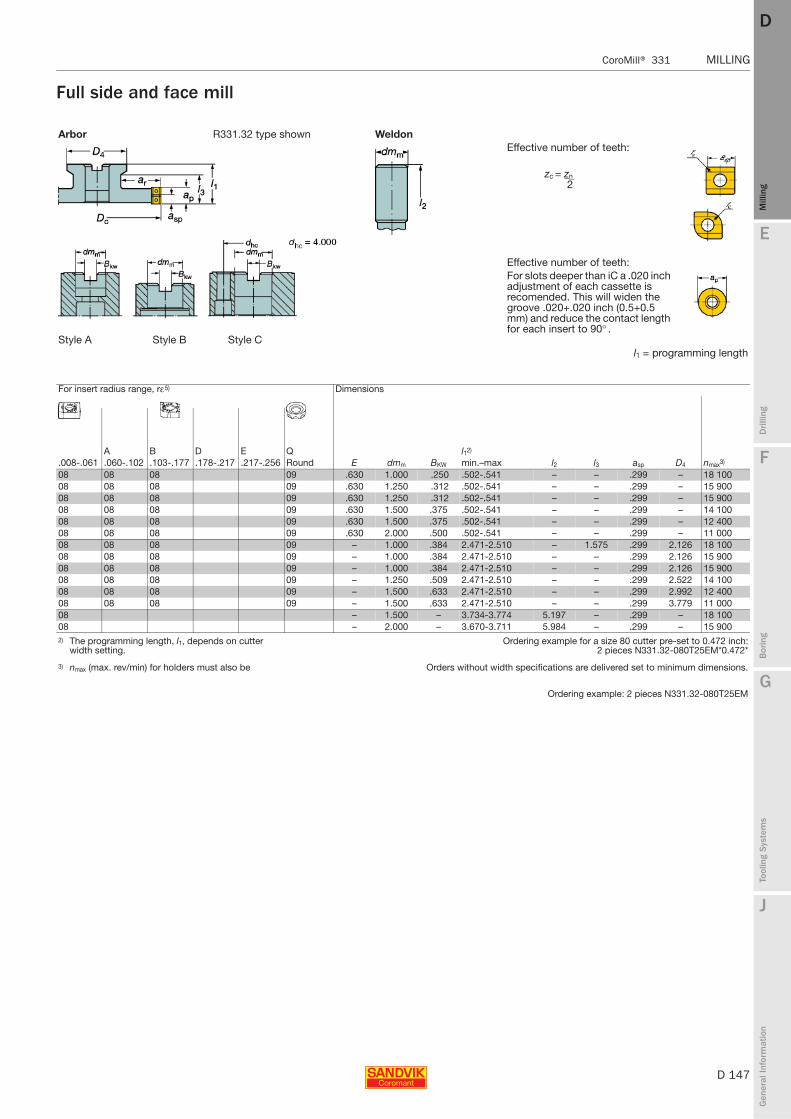
E
D 147
Mill
ing
Drilli
ng
F
Bor
ing
G
Tool
ing
Syst
ems
J
Gen
eral
Info
rmat
ion
DD
Mill
ing
CoroMill® 331 MILLING
MILLING CoroMill® 331
Full side and face mill
Arbor R331.32 type shown WeldonEffective number of teeth:
zc = zn 2
Effective number of teeth:For slots deeper than iC a .020 inch adjustment of each cassette is recomended. This will widen the groove .020+.020 inch (0.5+0.5 mm) and reduce the contact length for each insert to 90° .
Style A Style B Style Cl1 = programming length
For insert radius range, rε5) Dimensions
A B D E Q l12)
.008-.061 .060-.102 .103-.177 .178-.217 .217-.256 Round E dmm BKW min.–max l2 l3 asp D4 nmax3)
08 08 08 09 .630 1.000 .250 .502-.541 – – .299 – 18 10008 08 08 09 .630 1.250 .312 .502-.541 – – .299 – 15 90008 08 08 09 .630 1.250 .312 .502-.541 – – .299 – 15 90008 08 08 09 .630 1.500 .375 .502-.541 – – .299 – 14 10008 08 08 09 .630 1.500 .375 .502-.541 – – .299 – 12 40008 08 08 09 .630 2.000 .500 .502-.541 – – .299 – 11 00008 08 08 09 – 1.000 .384 2.471-2.510 – 1.575 .299 2.126 18 10008 08 08 09 – 1.000 .384 2.471-2.510 – – .299 2.126 15 90008 08 08 09 – 1.000 .384 2.471-2.510 – – .299 2.126 15 90008 08 08 09 – 1.250 .509 2.471-2.510 – – .299 2.522 14 10008 08 08 09 – 1.500 .633 2.471-2.510 – – .299 2.992 12 40008 08 08 09 – 1.500 .633 2.471-2.510 – – .299 3.779 11 00008 – 1.500 – 3.734-3.774 5.197 – .299 – 18 10008 – 2.000 – 3.670-3.711 5.984 – .299 – 15 9002) The programming length, l1, depends on cutter
width setting.Ordering example for a size 80 cutter pre-set to 0.472 inch:
2 pieces N331.32-080T25EM*0.472*
3) nmax (max. rev/min) for holders must also be Orders without width specifications are delivered set to minimum dimensions.
Ordering example: 2 pieces N331.32-080T25EM
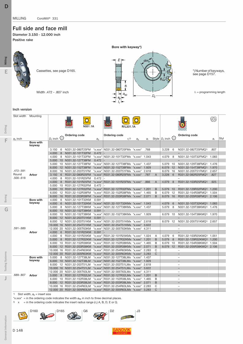
D 148
MILLING CoroMill® 331
E
Mill
ing
Drilli
ng
F
Bor
ing
G
Tool
ing
Syst
ems
J
Gen
eral
Info
rmat
ion
DDM
illin
g
MILLING CoroMill® 331
Full side and face millDiameter 3.150 - 12.000 inchPositive rake
Bore with keyway*)
Cassettes, see page D165. *) Number of keyways, see page D157.
Width .472 - .807 inch l1 = programming length
Inch version
Slot width Mounting
ap inchOrdering code Ordering code Ordering code
Dc inch b ap rε5) ap ar Style Dc inch b ar StylBore with keyway
3.150 6 N331.32-080T25FM *x.xxx* N331.32-080T25FMx *x.xxx* .768 3.228 6 N331.32-082T25FMQ1) .8074.000 8 N331.32-101T32FM 0.472 - –4.000 8 N331.32-101T32FM *x.xxx* N331.32-101T32FMx *x.xxx* 1.043 4.079 8 N331.32-103T32FMQ1) 1.0835.000 10 N331.32-127T38FM 0.472 - –5.000 10 N331.32-127T38FM *x.xxx* N331.32-127T38FMx *x.xxx* 1.437 5.079 10 N331.32-129T38FMQ1) 1.4766.000 12 N331.32-152T38FM *x.xxx* N331.32-152T38FMx *x.xxx* 1.929 6.079 12 N331.32-154T38FMQ1) 1.970
.472-.591 8.000 16 N331.32-203T51FM *x.xxx* N331.32-203T51FMx *x.xxx* 2.618 8.079 16 N331.32-205T51FMQ1) 2.657Round Arbor 3.150 6 R331.32-080R25FM *x.xxx* R331.32-080R25FMx *x.xxx* .787 A 3.228 6 R331.32-082R25FMQ1) .827.500-.618 4.000 8 R331.32-101R25FM 0.472 - –
4.000 8 R331.32-101R25FM *x.xxx* R331.32-101R25FMx *x.xxx* .866 A 4.079 8 R331.32-103R25FMQ1) .9255.000 10 R331.32-127R32FM 0.472 - –5.000 10 R331.32-127R32FM *x.xxx* R331.32-127R32FMx *x.xxx* 1.201 B 5.079 10 R331.32-129R32FMQ1) 1.2006.000 12 R331.32-152R38FM *x.xxx* R331.32-152R38FMx *x.xxx* 1.465 B 6.079 12 R331.32-154R38FMQ1) 1.5048.000 16 R331.32-203R38FM *x.xxx* R331.32-203R38FMx *x.xxx* 2.071 B 8.079 16 R331.32-205R38FMQ1) 2.106
Bore with keyway
4.000 6 N331.32-101T32KM 0.591 - –4.000 6 N331.32-101T32KM *x.xxx* N331.32-101T32KMx *x.xxx* 1.043 4.079 6 N331.32-103T32KMQ1) 1.0835.000 8 N331.32-127T38KM *x.xxx* N331.32-127T38KMx *x.xxx* 1.437 5.079 8 N331.32-129T38KMQ1) 1.4766.000 10 N331.32-152T38KM 0.591 - –6.000 10 N331.32-152T38KM *x.xxx* N331.32-152T38KMx *x.xxx* 1.929 6.079 10 N331.32-154T38KMQ1) 1.9708.000 12 N331.32-203T51KM 0.591 - –8.000 12 N331.32-203T51KM *x.xxx* N331.32-203T51KMx *x.xxx* 2.618 8.079 12 N331.32-205T51KMQ1) 2.657
10.000 16 N331.32-254T51KM *x.xxx* N331.32-254T51KMx *x.xxx* 3.622 –.591-.689 12.000 20 N331.32-305T63KM *x.xxx* N331.32-305T63KMx *x.xxx* 4.311 –
Arbor 4.000 6 R331.32-101R25KM 0.591 - –4.000 6 R331.32-101R25KM *x.xxx* R331.32-101R25KMx *x.xxx* 1.024 A 4.079 6 R331.32-103R25KMQ1) 1.0515.000 8 R331.32-127R32KM *x.xxx* R331.32-127R32KMx *x.xxx* 1.201 B 5.079 8 R331.32-129R32KMQ1) 1.2006.000 10 R331.32-152R38KM *x.xxx* R331.32-152R38KMx *x.xxx* 1.465 B 6.079 10 R331.32-154R38KMQ1) 1.5048.000 12 R331.32-203R38KM *x.xxx* R331.32-203R38KMx *x.xxx* 2.071 B 8.079 12 R331.32-205R38KMQ1) 2.106
10.000 16 R331.32-254R63KM *x.xxx* R331.32-254R63KMx *x.xxx* 2.283 C –12.000 20 R331.32-305R63KM *x.xxx* R331.32-305R63KMx *x.xxx* 3.283 C –
Bore with keyway
5.000 8 N331.32-127T38LM *x.xxx* N331.32-127T38LMx *x.xxx* 1.437 –6.000 10 N331.32-152T38LM *x.xxx* N331.32-152T38LMx *x.xxx* 1.929 –8.000 12 N331.32-203T51LM *x.xxx* N331.32-203T51LMx *x.xxx* 2.618 –
10.000 16 N331.32-254T51LM *x.xxx* N331.32-254T51LMx *x.xxx* 3.622 –12.000 20 N331.32-305T63LM *x.xxx* N331.32-305T63LMx *x.xxx* 4.311 –
.689-.807 Arbor 5.000 8 R331.32-127R32LM *x.xxx* R331.32-127R32LMx *x.xxx* 1.201 B –6.000 10 R331.32-152R38LM *x.xxx* R331.32-152R38LMx *x.xxx* 1.465 B –8.000 12 R331.32-203R38LM *x.xxx* R331.32-203R38LMx *x.xxx* 2.071 B –
10.000 16 R331.32-254R63LM *x.xxx* R331.32-254R63LMx *x.xxx* 2.283 C –12.000 20 R331.32-305R63LM *x.xxx* R331.32-305R63LMx *x.xxx* 3.283 C –
1) Slot width, ap = insert size*x.xxx* = in the ordering code indicates the width aBp in inch to three decimal places.5) x = in the ordering code indicates the insert radius range (rε) A, B, D, E or Q.
D160 D165 G6 D2 J3
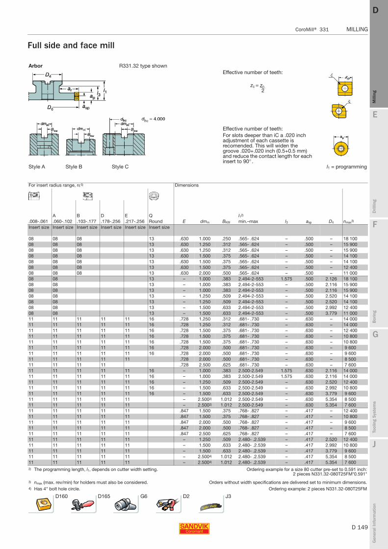
E
D 149
Mill
ing
Drilli
ng
F
Bor
ing
G
Tool
ing
Syst
ems
J
Gen
eral
Info
rmat
ion
DD
Mill
ing
CoroMill® 331 MILLING
MILLING CoroMill® 331
Full side and face mill
Arbor R331.32 type shownEffective number of teeth:
zc = zn 2
Effective number of teeth:For slots deeper than iC a .020 inch adjustment of each cassette is recomended. This will widen the groove .020+.020 inch (0.5+0.5 mm) and reduce the contact length for each insert to 90° .
Style A Style B Style C l1 = programming
For insert radius range, rε5) Dimensions
A B D E Q l12)
.008-.061 .060-.102 .103-.177 .178-.256 .217-.256 Round E dmm BKW min.–max l3 asp D4 nmax3)
Insert size Insert size Insert size Insert size Insert size Insert size
08 08 08 13 .630 1.000 .250 .565- .624 – .500 – 18 10008 08 08 13 .630 1.250 .312 .565- .624 – .500 – 15 90008 08 08 13 .630 1.250 .312 .565- .624 – .500 – 15 90008 08 08 13 .630 1.500 .375 .565- .624 – .500 – 14 10008 08 08 13 .630 1.500 .375 .565- .624 – .500 – 14 10008 08 08 13 .630 1.500 .375 .565- .624 – .500 – 12 40008 08 08 13 .630 2.000 .500 .565- .624 – .500 – 11 00008 08 13 – 1.000 .383 2.494-2-553 1.575 .500 2.126 18 10008 08 13 – 1.000 .383 2.494-2-553 – .500 2.116 15 90008 08 13 – 1.000 .383 2.494-2-553 – .500 2.116 15 90008 08 13 – 1.250 .509 2.494-2-553 – .500 2.520 14 10008 08 13 – 1.250 .509 2.494-2-553 – .500 2.520 14 10008 08 13 – 1.500 .633 2.494-2-553 – .500 2.992 12 40008 08 13 – 1.500 .633 2.494-2-553 – .500 3.779 11 00011 11 11 11 11 16 .728 1.250 .312 .681- .730 – .630 – 14 00011 11 11 11 11 16 .728 1.250 .312 .681- .730 – .630 – 14 00011 11 11 11 11 16 .728 1.500 .375 .681- .730 – .630 – 12 40011 11 11 11 11 16 .728 1.500 .375 .681- .730 – .630 – 10 80011 11 11 11 11 16 .728 1.500 .375 .681- .730 – .630 – 10 80011 11 11 11 11 16 .728 2.000 .500 .681- .730 – .630 – 9 60011 11 11 11 11 16 .728 2.000 .500 .681- .730 – .630 – 9 60011 11 11 11 11 .728 2.000 .500 .681- .730 – .630 – 8 50011 11 11 11 .728 2.500 .625 .681- .730 – .630 – 7 60011 11 11 11 11 16 – 1.000 .383 2.500-2.549 1.575 .630 2.116 14 00011 11 11 11 11 16 – 1.000 .383 2.500-2.549 1.575 .630 2.116 14 00011 11 11 11 11 16 – 1.250 .509 2.500-2.549 – .630 2.520 12 40011 11 11 11 11 16 – 1.500 .633 2.500-2.549 – .630 2.992 10 80011 11 11 11 11 16 – 1.500 .633 2.500-2.549 – .630 3.779 9 60011 11 11 11 11 – 2.5002) 1.012 2.500-2.549 – .630 5.354 8 50011 11 11 11 11 – 2.5002) 1.012 2.500-2.549 – .630 5.354 7 60011 11 11 11 11 .847 1.500 .375 .768- .827 – .417 – 12 40011 11 11 11 11 .847 1.500 .375 .768- .827 – .417 – 10 80011 11 11 11 11 .847 2.000 .500 .768- .827 – .417 – 9 60011 11 11 11 11 .847 2.000 .500 .768- .827 – .417 – 8 50011 11 11 11 11 .847 2.500 .625 .768- .827 – .417 – 7 60011 11 11 11 11 – 1.250 .509 2.480- .2.539 – .417 2.520 12 40011 11 11 11 11 – 1.500 .633 2.480- .2.539 – .417 2.992 10 80011 11 11 11 11 – 1.500 .633 2.480- .2.539 – .417 3.779 9 60011 11 11 11 11 – 2.5004) 1.012 2.480- .2.539 – .417 5.354 8 50011 11 11 11 11 – 2.5004) 1.012 2.480- .2.539 – .417 5.354 7 6002) The programming length, l1, depends on cutter width setting. Ordering example for a size 80 cutter pre-set to 0.591 inch:
2 pieces N331.32-080T25FM*0.591*
3) nmax (max. rev/min) for holders must also be considered. Orders without width specifications are delivered set to minimum dimensions.4) Has 4" bolt hole circle. Ordering example: 2 pieces N331.32-080T25FM
D160 D165 G6 D2 J3
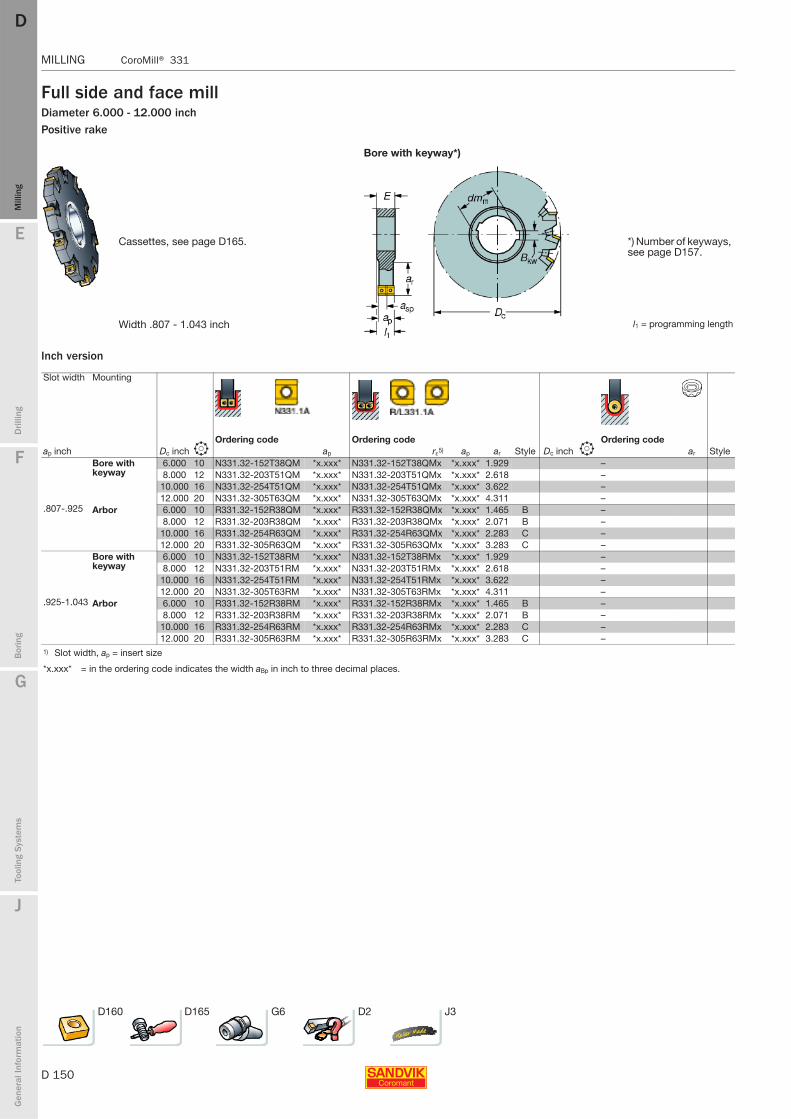
D 150
MILLING CoroMill® 331
E
Mill
ing
Drilli
ng
F
Bor
ing
G
Tool
ing
Syst
ems
J
Gen
eral
Info
rmat
ion
DDM
illin
g
MILLING CoroMill® 331
Full side and face millDiameter 6.000 - 12.000 inchPositive rake
Bore with keyway*)
Cassettes, see page D165. *) Number of keyways, see page D157.
Width .807 - 1.043 inch l1 = programming length
Inch version
Slot width Mounting
ap inchOrdering code Ordering code Ordering code
Dc inch b ap rε5) ap ar Style Dc inch b ar StyleBore with keyway
6.000 10 N331.32-152T38QM *x.xxx* N331.32-152T38QMx *x.xxx* 1.929 –8.000 12 N331.32-203T51QM *x.xxx* N331.32-203T51QMx *x.xxx* 2.618 –
10.000 16 N331.32-254T51QM *x.xxx* N331.32-254T51QMx *x.xxx* 3.622 –12.000 20 N331.32-305T63QM *x.xxx* N331.32-305T63QMx *x.xxx* 4.311 –
.807-.925 Arbor 6.000 10 R331.32-152R38QM *x.xxx* R331.32-152R38QMx *x.xxx* 1.465 B –8.000 12 R331.32-203R38QM *x.xxx* R331.32-203R38QMx *x.xxx* 2.071 B –
10.000 16 R331.32-254R63QM *x.xxx* R331.32-254R63QMx *x.xxx* 2.283 C –12.000 20 R331.32-305R63QM *x.xxx* R331.32-305R63QMx *x.xxx* 3.283 C –
Bore with keyway
6.000 10 N331.32-152T38RM *x.xxx* N331.32-152T38RMx *x.xxx* 1.929 –8.000 12 N331.32-203T51RM *x.xxx* N331.32-203T51RMx *x.xxx* 2.618 –
10.000 16 N331.32-254T51RM *x.xxx* N331.32-254T51RMx *x.xxx* 3.622 –12.000 20 N331.32-305T63RM *x.xxx* N331.32-305T63RMx *x.xxx* 4.311 –
.925-1.043 Arbor 6.000 10 R331.32-152R38RM *x.xxx* R331.32-152R38RMx *x.xxx* 1.465 B –8.000 12 R331.32-203R38RM *x.xxx* R331.32-203R38RMx *x.xxx* 2.071 B –
10.000 16 R331.32-254R63RM *x.xxx* R331.32-254R63RMx *x.xxx* 2.283 C –12.000 20 R331.32-305R63RM *x.xxx* R331.32-305R63RMx *x.xxx* 3.283 C –
1) Slot width, ap = insert size
*x.xxx* = in the ordering code indicates the width aBp in inch to three decimal places.
D160 D165 G6 D2 J3
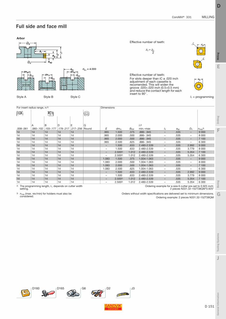
E
D 151
Mill
ing
Drilli
ng
F
Bor
ing
G
Tool
ing
Syst
ems
J
Gen
eral
Info
rmat
ion
DD
Mill
ing
CoroMill® 331 MILLING
MILLING CoroMill® 331
Full side and face mill
ArborEffective number of teeth:
zc = zn 2
Effective number of teeth:For slots deeper than iC a .020 inch adjustment of each cassette is recomended. This will widen the groove .020+.020 inch (0.5+0.5 mm) and reduce the contact length for each insert to 90° .
Style A Style B Style C l1 = programming
For insert radius range, rε5) Dimensions
A B D E Q l12)
.008-.061 .060-.102 .103-.177 .178-.217 .217-.256 Round E dmm BKW min.–max l3 asp D4 nmax3)
14 14 14 14 14 .965 1.500 .375 .886- .945 – .535 – 9 00014 14 14 14 14 .965 2.000 .500 .886- .945 – .535 – 8 00014 14 14 14 14 .965 2.000 .500 .886- .945 – .535 – 7 10014 14 14 14 14 .965 2.500 .625 .886- .945 – .535 – 6 30014 14 14 14 14 – 1.500 .633 2.480-2.539 – .535 2.992 9 00014 14 14 14 14 – 1.500 .633 2.480-2.539 – .535 3.779 8 00014 14 14 14 14 – 2.5002) 1.012 2.480-2.539 – .535 5.354 7 10014 14 14 14 14 – 2.5002) 1.012 2.480-2.539 – .535 5.354 6 30014 14 14 14 14 1.083 1.500 .375 1.004-1.063 – .535 – 9 00014 14 14 14 14 1.083 2.000 .500 1.004-1.063 – .535 – 8 00014 14 14 14 14 1.083 2.000 .500 1.004-1.063 – .535 – 7 10014 14 14 14 14 1.083 2.500 .625 1.004-1.063 – .535 – 6 30014 14 14 14 14 – 1.500 .633 2.480-2.539 – .535 2.992 9 00014 14 14 14 14 – 1.500 .633 2.480-2.539 – .535 3.779 8 00014 14 14 14 14 – 2.5002) 1.012 2.480-2.539 – .535 5.354 7 10014 14 14 14 14 – 2.5002) 1.012 2.480-2.539 – .535 5.354 6 3002) The programming length, l1, depends on cutter width
setting.Ordering example for a size 6 cutter pre-set to 0.925 inch:
2 pieces N331.32-152T38QM*0.925*
3) nmax (max. rev/min) for holders must also be considered.
Orders without width specifications are delivered set to minimum dimensions.Ordering example: 2 pieces N331.32-152T38QM
D160 D165 G6 D2 J3
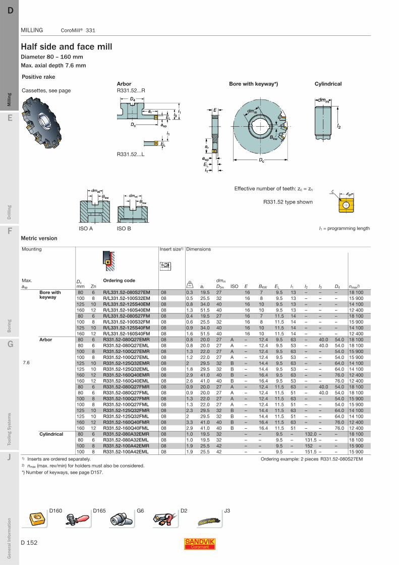
D 152
MILLING CoroMill® 331
E
Mill
ing
Drilli
ng
F
Bor
ing
G
Tool
ing
Syst
ems
J
Gen
eral
Info
rmat
ion
DDM
illin
g
MILLING CoroMill® 331
Half side and face millDiameter 80 – 160 mmMax. axial depth 7.6 mm
Metric version
Positive rakeArbor Bore with keyway*) Cylindrical
Cassettes, see page R331.52...R
R331.52...L
Effective number of teeth: zc = zn
R331.52 type shown
ISO A ISO B l1 = programming length
Mounting Insert size1) Dimensions
Max. Dc mm
Ordering code dmm
asp Zn U ar D5m ISO E BKW EL l1 l2 l3 D4 nmax2)
Bore with keyway
80 6 R/L331.52-080S27EM 08 0.3 19.5 27 16 7 9.5 13 – – – 18 100100 8 R/L331.52-100S32EM 08 0.5 25.5 32 16 8 9.5 13 – – – 15 900125 10 R/L331.52-125S40EM 08 0.8 34.0 40 16 10 9.5 13 – – – 14 100160 12 R/L331.52-160S40EM 08 1.3 51.5 40 16 10 9.5 13 – – – 12 40080 6 R/L331.52-080S27FM 08 0.4 19.5 27 16 7 11.5 14 – – – 18 100
100 8 R/L331.52-100S32FM 08 0.6 25.5 32 16 8 11.5 14 – – – 15 900125 10 R/L331.52-125S40FM 08 0.9 34.0 40 16 10 11.5 14 – – – 14 100160 12 R/L331.52-160S40FM 08 1.6 51.5 40 16 10 11.5 14 – – – 12 400
Arbor 80 6 R331.52-080Q27EMR 08 0.8 20.0 27 A – 12.4 9.5 63 – 40.0 54.0 18 10080 6 R331.52-080Q27EML 08 0.8 20.0 27 A – 12.4 9.5 53 – 40.0 54.0 18 100
100 8 R331.52-100Q27EMR 08 1.3 22.0 27 A – 12.4 9.5 63 – – 54.0 15 900100 8 R331.52-100Q27EML 08 1.2 22.0 27 A – 12.4 9.5 53 – – 54.0 15 900
7.6 125 10 R331.52-125Q32EMR 08 2 29.5 32 B – 14.4 9.5 63 – – 64.0 14 100125 10 R331.52-125Q32EML 08 1.8 29.5 32 B – 14.4 9.5 53 – – 64.0 14 100160 12 R331.52-160Q40EMR 08 2.9 41.0 40 B – 16.4 9.5 63 – – 76.0 12 400160 12 R331.52-160Q40EML 08 2.6 41.0 40 B – 16.4 9.5 53 – – 76.0 12 40080 6 R331.52-080Q27FMR 08 0.9 20.0 27 A – 12.4 11.5 63 – 40.0 54.0 18 10080 6 R331.52-080Q27FML 08 0.9 20.0 27 A – 12.4 11.5 51 – 40.0 54.0 18 100
100 8 R331.52-100Q27FMR 08 1.3 22.0 27 A – 12.4 11.5 63 – – 54.0 15 900100 8 R331.52-100Q27FML 08 1.3 22.0 27 A – 12.4 11.5 51 – – 54.0 15 900125 10 R331.52-125Q32FMR 08 2.3 29.5 32 B – 14.4 11.5 63 – – 64.0 14 100125 10 R331.52-125Q32FML 08 2 29.5 32 B – 14.4 11.5 51 – – 64.0 14 100160 12 R331.52-160Q40FMR 08 3.3 41.0 40 B – 16.4 11.5 63 – – 76.0 12 400160 12 R331.52-160Q40FML 08 2.9 41.0 40 B – 16.4 11.5 51 – – 76.0 12 400
Cylindrical 80 6 R331.52-080A32EMR 08 1.0 19.5 32 – – 9.5 – 132.0 – – 18 10080 6 R331.52-080A32EML 08 1.0 19.5 32 – – 9.5 – 131.5 – – 18 100
100 8 R331.52-100A42EMR 08 1.9 25.5 42 – – 9.5 – 152 – – 15 900100 8 R331.52-100A42EML 08 1.9 25.5 42 – – 9.5 – 151.5 – – 15 900
1) Inserts are ordered separately. Ordering example: 2 pieces R331.52-080S27EM2) nmax (max. rev/min) for holders must also be considered.*) Number of keyways, see page D157.
D160 D165 G6 D2 J3
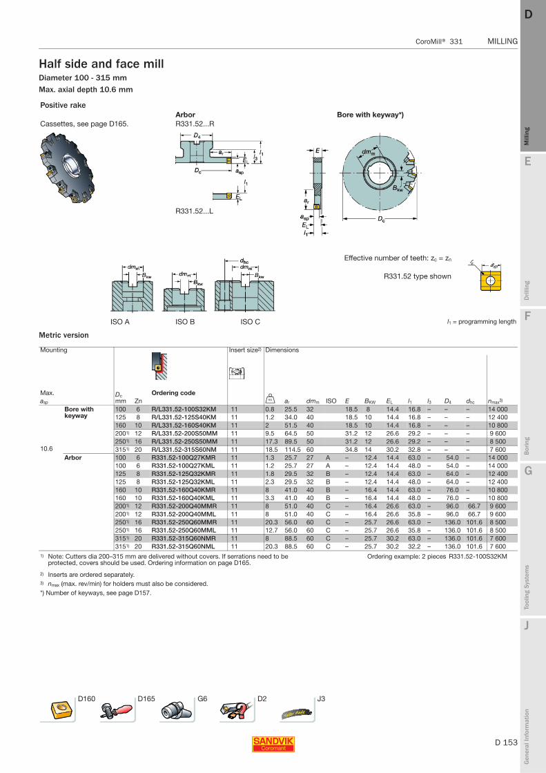
E
D 153
Mill
ing
Drilli
ng
F
Bor
ing
G
Tool
ing
Syst
ems
J
Gen
eral
Info
rmat
ion
DD
Mill
ing
CoroMill® 331 MILLING
MILLING CoroMill® 331
Half side and face millDiameter 100 - 315 mmMax. axial depth 10.6 mm
Metric version
Positive rakeArbor Bore with keyway*)
Cassettes, see page D165. R331.52...R
R331.52...L
Effective number of teeth: zc = zn
R331.52 type shown
ISO A ISO B ISO C l1 = programming length
Mounting Insert size2) Dimensions
Max. Dc mm
Ordering codeasp Zn U ar dmm ISO E BKW EL l1 l3 D4 dhc nmax3)
Bore with keyway
100 6 R/L331.52-100S32KM 11 0.8 25.5 32 18.5 8 14.4 16.8 – – – 14 000125 8 R/L331.52-125S40KM 11 1.2 34.0 40 18.5 10 14.4 16.8 – – – 12 400160 10 R/L331.52-160S40KM 11 2 51.5 40 18.5 10 14.4 16.8 – – – 10 8002001) 12 R/L331.52-200S50MM 11 9.5 64.5 50 31.2 12 26.6 29.2 – – – 9 6002501) 16 R/L331.52-250S50MM 11 17.3 89.5 50 31.2 12 26.6 29.2 – – – 8 500
10.6 3151) 20 R/L331.52-315S60NM 11 18.5 114.5 60 34.8 14 30.2 32.8 – – – 7 600Arbor 100 6 R331.52-100Q27KMR 11 1.3 25.7 27 A – 12.4 14.4 63.0 – 54.0 – 14 000
100 6 R331.52-100Q27KML 11 1.2 25.7 27 A – 12.4 14.4 48.0 – 54.0 – 14 000125 8 R331.52-125Q32KMR 11 1.8 29.5 32 B – 12.4 14.4 63.0 – 64.0 – 12 400125 8 R331.52-125Q32KML 11 2.3 29.5 32 B – 12.4 14.4 48.0 – 64.0 – 12 400160 10 R331.52-160Q40KMR 11 8 41.0 40 B – 16.4 14.4 63.0 – 76.0 – 10 800160 10 R331.52-160Q40KML 11 3.3 41.0 40 B – 16.4 14.4 48.0 – 76.0 – 10 8002001) 12 R331.52-200Q40MMR 11 8 51.0 40 C – 16.4 26.6 63.0 – 96.0 66.7 9 6002001) 12 R331.52-200Q40MML 11 8 51.0 40 C – 16.4 26.6 35.8 – 96.0 66.7 9 6002501) 16 R331.52-250Q60MMR 11 20.3 56.0 60 C – 25.7 26.6 63.0 – 136.0 101.6 8 5002501) 16 R331.52-250Q60MML 11 12.7 56.0 60 C – 25.7 26.6 35.8 – 136.0 101.6 8 5003151) 20 R331.52-315Q60NMR 11 8 88.5 60 C – 25.7 30.2 63.0 – 136.0 101.6 7 6003151) 20 R331.52-315Q60NML 11 20.3 88.5 60 C – 25.7 30.2 32.2 – 136.0 101.6 7 600
1) Note: Cutters dia 200–315 mm are delivered without covers. If serrations need to be protected, covers should be used. Ordering information on page D165.
Ordering example: 2 pieces R331.52-100S32KM
2) Inserts are ordered separately.3) nmax (max. rev/min) for holders must also be considered.*) Number of keyways, see page D157.
D160 D165 G6 D2 J3

D 154
MILLING CoroMill® 331
E
Mill
ing
Drilli
ng
F
Bor
ing
G
Tool
ing
Syst
ems
J
Gen
eral
Info
rmat
ion
DDM
illin
g
MILLING CoroMill® 331
Half side and face millDiameter 3.150 - 6.000 inchMax. axial depth .299 inch
Inch version
Positive rakeArbor Bore with keyway*) Weldon
Cassettes, see page R331.52...R
R331.52...L
Effective number of teeth: zc = zn
R331.52 type shown
ISO A ISO B l1 = programming length
Mounting Insert size1) Dimensions
Max. Dc inch Ordering code dmmasp Zn ar ISO E BKW Ci EL l1 l2 l3 D4 nmax2)
Bore with keyway
3.150 6 R/L331.52-080T25EM .768 1.000 08 .630 .250 1.102 .374 .512 – – – 18 1004.000 8 R/L331.52-101T32EM 1.043 1.250 08 .630 .312 1.136 .374 .512 – – – 15 9005.000 10 R/L331.52-127T38EM 1.437 1.500 08 .630 .375 1.666 .374 .512 – – – 14 1006.000 12 R/L331.52-152T38EM 1.929 1.500 08 .630 .375 1.666 .374 .512 – – – 12 4003.150 6 R/L331.52-080T25FM .768 1.000 08 .630 .250 1.102 .453 .551 – – – 18 1004.000 8 R/L331.52-101T32FM 1.043 1.250 08 .630 .312 1.136 .453 .551 – – – 15 9005.000 10 R/L331.52-127T38FM 1.437 1.500 08 .630 .375 1.666 .453 .551 – – – 14 1006.000 12 R/L331.52-152T38FM 1.929 1.500 08 .630 .375 1.666 .453 .551 – – – 12 400
Arbor 3.150 6 R331.52-080R25EMR .787 1.000 A 08 – .384 .374 2.480 – 1.575 2.126 18 1003.150 6 R331.52-080R25EML .787 1.000 A 08 – .384 .374 2.087 – 1.181 2.126 18 1004.000 8 R331.52-101R25EMR .866 1.000 A 08 – .384 .374 2.480 – – 2.126 15 9004.000 8 R331.52-101R25EML .866 1.000 A 08 – .384 .374 2.087 – – 2.126 15 900
.299 5.000 10 R331.52-127R32EMR 1.201 1.250 B 08 – .509 .374 2.480 – – 2.520 14 1005.000 10 R331.52-127R32EML 1.201 1.250 B 08 – .509 .374 2.087 – – 2.520 14 1006.000 12 R331.52-152R38EMR 1.464 1.500 B 08 – .633 .374 2.480 – – 2.992 12 4006.000 12 R331.52-152R38EML 1.464 1.500 B 08 – .633 .374 2.087 – – 2.992 12 4003.150 6 R331.52-080R25FMR .787 1.000 A 08 – .384 .453 2.480 – 1.575 2.126 18 1003.150 6 R331.52-080R25FML .787 1.000 A 08 – .384 .453 2.008 – 1.102 2.126 18 1004.000 8 R331.52-101R25FMR .866 1.000 A 08 – .384 .453 2.480 – – 2.126 15 9004.000 8 R331.52-101R25FML .866 1.000 A 08 – .384 .453 2.008 – – 2.126 15 9005.000 10 R331.52-127R32FMR 1.201 1.250 B 08 – .509 .453 2.480 – – 2.520 14 1005.000 10 R331.52-127R32FML 1.201 1.250 B 08 – .509 .453 2.008 – – 2.520 14 1006.000 12 R331.52-152R38FMR 1.464 1.500 B 08 – .633 .453 2.480 – – 2.992 12 4006.000 12 R331.52-152R38FML 1.464 1.500 B 08 – .633 .453 2.008 – – 2.992 12 400
Weldon 3.150 6 R331.52-080M38EMR .787 1.250 08 – – .374 3.734 4.921 – – 18 1003.150 6 R331.52-080M38EML .787 1.250 08 – – .374 3.734 4.921 – – 18 1004.000 8 R331.52-101M51EMR .945 2.000 08 – – .374 3.670 5.512 – – 15 9004.000 8 R331.52-101M51EML .945 2.000 08 – – .374 3.276 5.512 – – 15 900
1) Inserts are ordered separately. Ordering example: 2 pieces R331.52-080T25EM2) nmax (max. rev/min) for holders must also be considered.*) Number of keyways, see page D157.
D160 D165 G6 D2 J3

E
D 155
Mill
ing
Drilli
ng
F
Bor
ing
G
Tool
ing
Syst
ems
J
Gen
eral
Info
rmat
ion
DD
Mill
ing
CoroMill® 331 MILLING
MILLING CoroMill® 331
Half side and face millDiameter 4.000 - 12.000 inchMax. axial depth .417 inch
Inch version
Positive rakeArbor Bore with keyway*)
Cassettes, see page D165. R331.52...R
R331.52...L
Effective number of teeth: zc = zn
R331.52 type shown
ISO A ISO B ISO C l1 = programming length
Mounting Insert size1) Dimensions
Max. Dc inch
Ordering codeasp Zn ar dmm ISO E BKW Ci EL l1 l3 D4 nmax2)
Bore with keyway
4.000 6 R/L331.52-101T32KM 1.043 1.250 11 .728 .312 1.386 .567 .661 – – 14 0005.000 8 R/L331.52-127T38KM 1.437 1.500 11 .728 .375 1.666 .567 .661 – – 12 4006.000 10 R/L331.52-152T38KM 1.929 1.500 11 .728 .375 1.666 .567 .661 – – 10 8008.000 12 R/L331.52-203T51MM 2.618 2.000 11 1.228 .500 2.197 1.047 1.150 – – 9 60010.00 16 R/L331.52-254T51MM 3.622 2.000 11 1.228 .500 2.197 1.047 1.150 – – 8 500
.417 12.00 20 R/L331.52-305T63NM 4.311 2.500 11 1.370 .625 2.732 1.189 1.291 – – 7 600Arbor 4.000 6 R331.52-101R25KMR 1.024 1.000 A 11 – .384 .567 2.480 1.575 2.126 14 000
4.000 6 R331.52-101R25KML 1.024 1.000 A 11 – .384 .567 1.890 .984 2.126 14 0005.000 8 R331.52-127R32KMR 1.201 1.250 B 11 – .509 .567 2.480 – 2.520 12 4005.000 8 R331.52-127R32KML 1.201 1.250 B 11 – .509 .567 1.890 – 2.520 12 4006.000 10 R331.52-152R38KMR 1.464 1.500 B 11 – .633 .567 2.480 – 2.992 10 8006.000 10 R331.52-152R38KML 1.464 1.500 B 11 – .633 .567 1.890 – 2.992 10 8008.000 12 R331.52-203R38MMR 2.067 1.500 B 11 – .633 1.047 2.480 – 3.779 9 6008.000 12 R331.52-203R38MML 2.067 1.500 B 11 – .633 1.047 1.409 – 3.779 9 60010.00 16 R331.52-254R63MMR 2.283 2.500 C 11 – 1.012 1.047 2.480 – 5.354 8 50010.00 16 R331.52-254R63MML 2.283 2.500 C 11 – 1.012 1.047 1.409 – 5.354 8 50012.00 20 R331.52-305R63NMR 3.283 2.500 C 11 – 1.012 1.189 2.480 – 5.354 7 60012.00 20 R331.52-305R63NML 3.283 2.500 C 11 – 1.012 1.189 1.268 – 5.354 7 600
1) Inserts are ordered separately. Ordering example: 2 pieces R331.52-101T32KM2) nmax (max. rev/min) for holders must also be considered.*) Number of keyways, see page D157.
D160 D165 G6 D2 J3

D 156
MILLING CoroMill® 331
E
Mill
ing
Drilli
ng
F
Bor
ing
G
Tool
ing
Syst
ems
J
Gen
eral
Info
rmat
ion
DDM
illin
g
MILLING CoroMill® 331
Double half side and face millDiameter 200 - 315 mmPositive rake
Metric version
Cassettes, see page D165. Arbor Bore with keyway
Effective number of teeth: zc = zn
Width 27.2 - 33.8 mm ISO C l1 = programming length
Slot width Mounting Insert size1) Dimensions, mm
l1aBp mm Dc mm zn aBp U ar dmm ISO E BKW min.–max asp D4 dch nmax2)
Bore with keyway
200 24 N331.52-200S50MM*xx.xx* 11 9.5 64.5 50 31.2 12 29.2–30.7 10.6 – – 9600250 32 N331.52-250S50MM*xx.xx* 11 17.3 89.5 50 31.2 12 29.2–30.7 10.6 – – 8500
27.2–30.2Arbor 200 24 R331.52-200Q40MM*xx.xx* 11 8.0 51.0 40 C – 16.4 63.0–64.5 10.6 96.0 66.7 9600
250 32 R331.52-250Q60MM*xx.xx* 11 12.7 56.0 60 C – 25.7 63.0–64.5 10.6 136.0 101.6 8500Bore with keyway
315 32 N331.52-315S60NM*xx.xx* 11 18.5 114.5 60 34.8 14 32.8–34.3 10.6 – 760030.8–33.8
Arbor 315 24 R331.52-315Q60NM*xx.xx* 11 20.3 88.5 60 C – 25.7 63.0–64.5 10.6 136.0 101.6 8500
1) Inserts are ordered separately. Ordering example for a cutter pre-set to 27.32 mm:2 pieces N331.52-200S50MM*27.32*2) nmax (max. rev/min) for holders must also be considered.
Orders without width specifications are delivered set to minimum dimensions.
Ordering example: 2 pieces N331.52-200S50MM
*xx.xx* in the ordering code indicates the width aBp in mm to two decimal places.
One keyway Two keywaysPosition of the keyways for standard, Tailor Made and special 331 S/F milling cutters.
Cutters with a diameter larger than 124 mm and insert size 04, 05 or 08, and cutters with a diameter larger than 140 mm and insert size 11 or 14, have two keyways. The distance between the keyways is 180° minus half a pitch.
Cutters with a diameter smaller than 124 mm and insert size 04, 05 or 08 and cutters with a diameter smaller than 140 mm and insert size 11 or 14, have one keyway.
D160 D165 G6 D2 J3
N331.1A
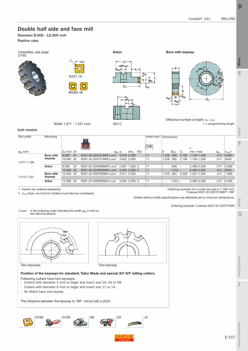
E
D 157
Mill
ing
Drilli
ng
F
Bor
ing
G
Tool
ing
Syst
ems
J
Gen
eral
Info
rmat
ion
DD
Mill
ing
CoroMill® 331 MILLING
MILLING CoroMill® 331
Double half side and face millDiameter 8.000 - 12.000 inchPositive rake
Inch version
Cassettes, see page D165.
Arbor Bore with keyway
Effective number of teeth: zc = zn
Width 1.071 - 1.331 inch ISO C l1 = programming length
Slot width Mounting Insert size1) Dimensions
Dc inchl1
aBp inch Zn aBp ar dmm ISO E BKW Ci min.–max asp nmax2)
Bore with keyway
8.000 24 N331.52-203T51MM*x.xxx* 2.618 2.000 11 1.228 .500 2.106 1.150-1.209 .417 9 60010.000 32 N331.52-254T51MM*x.xxx* 3.622 2.000 11 1.228 .500 2.106 1.150-1.209 .417 8500
1.071-1.189Arbor 8.000 24 R331.52-203R38MM*x.xxx* 2.067 1.500 C 11 – .646 – 2.480-2.539 .417 9 600
10.000 32 R331.52-254R63MM*x.xxx* 2.283 2.500 C 11 – 1.012 – 2.480-2.539 .417 8500Bore with keyway
12.000 40 N331.52-305T63NM*x.xxx* 4.311 2.500 11 1.370 .625 2.528 1.291-1.350 .417 7 6001.213-1.331
Arbor 12.000 40 R331.52-305R63NM*x.xxx* 3.283 2.500 C 11 – 1.012 – 2.480-2.539 .417 8 500
1) Inserts are ordered separately. Ordering example for a cutter pre-set to 1.189 inch:2 pieces N331.52-203T51MM*1.189*2) nmax (max. rev/min) for holders must also be considered.
Orders without width specifications are delivered set to minimum dimensions.
Ordering example: 2 pieces N331.52-203T51MM
*x.xxx* in the ordering code indicates the width aBp in inch to two decimal places.
Two keyways One keyway
Position of the keyways for standard, Tailor Made and special 331 S/F milling cutters.
Following cutters have two keyways:- Cutters with diameter 5 inch or larger and insert size 04, 05 or 08.- Cutters with diameter 6 inch or larger and insert size 11 or 14.- All others have one keyway.
The distance between the keyway is 180° minus half a pitch
D160 D165 G6 D2 J3
N331.1A
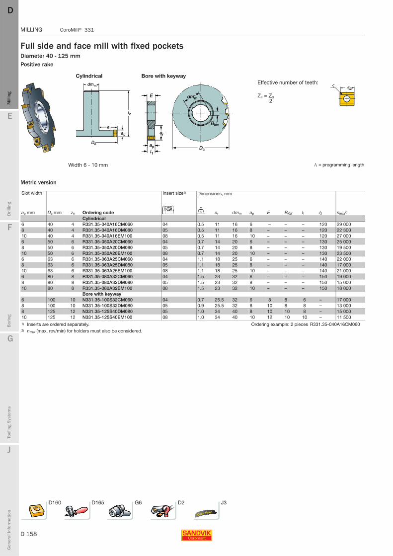
D 158
MILLING CoroMill® 331
E
Mill
ing
Drilli
ng
F
Bor
ing
G
Tool
ing
Syst
ems
J
Gen
eral
Info
rmat
ion
DDM
illin
g
MILLING CoroMill® 331
Full side and face mill with fixed pocketsDiameter 40 - 125 mmPositive rake
Cylindrical Bore with keywayEffective number of teeth:
Zc = Zn 2
Width 6 - 10 mm l1 = programming length
Metric version
Slot width Insert size1) Dimensions, mm
ap mm Dc mm zn Ordering code U ar dmm ap E BKW l1 l2 nmax2)
Cylindrical6 40 4 R331.35-040A16CM060 04 0.5 11 16 6 – – – 120 29 0008 40 4 R331.35-040A16DM080 05 0.5 11 16 8 – – – 120 22 30010 40 4 R331.35-040A16EM100 08 0.5 11 16 10 – – – 120 27 0006 50 6 R331.35-050A20CM060 04 0.7 14 20 6 – – – 130 25 0008 50 6 R331.35-050A20DM080 05 0.7 14 20 8 – – – 130 19 50010 50 6 R331.35-050A20EM100 08 0.7 14 20 10 – – – 130 23 5006 63 6 R331.35-063A25CM060 04 1.1 18 25 6 – – – 140 22 0008 63 6 R331.35-063A25DM080 05 1.1 18 25 8 – – – 140 17 00010 63 6 R331.35-063A25EM100 08 1.1 18 25 10 – – – 140 21 0006 80 8 R331.35-080A32CM060 04 1.5 23 32 6 – – – 150 19 0008 80 8 R331.35-080A32DM080 05 1.5 23 32 8 – – – 150 15 00010 80 8 R331.35-080A32EM100 08 1.5 23 32 10 – – – 150 18 000
Bore with keyway6 100 10 N331.35-100S32CM060 04 0.7 25.5 32 6 8 8 6 – 17 0008 100 10 N331.35-100S32DM080 05 0.9 25.5 32 8 10 8 8 – 13 0008 125 12 N331.35-125S40DM080 05 1.0 34 40 8 10 10 8 – 15 00010 125 12 N331.35-125S40EM100 08 1.0 34 40 10 12 10 10 – 11 5001) Inserts are ordered separately. Ordering example: 2 pieces R331.35-040A16CM0602) nmax (max. rev/min) for holders must also be considered.
D160 D165 G6 D2 J3
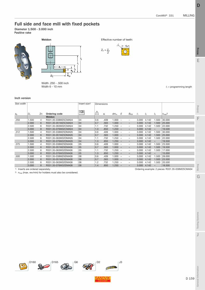
E
D 159
Mill
ing
Drilli
ng
F
Bor
ing
G
Tool
ing
Syst
ems
J
Gen
eral
Info
rmat
ion
DD
Mill
ing
CoroMill® 331 MILLING
MILLING CoroMill® 331
Full side and face mill with fixed pocketsDiameter 1.500 - 3.000 inchPositive rake
Weldon Effective number of teeth:
Zc = Zn 2
Width .250 - .500 inchWidth 6 - 10 mm l1 = programming length
Inch version
Slot width Insert size1) Dimensions
ap Dc Zn Ordering code U ar dmm E BKW l1 l2 l3 nmax2)
Weldon.250 1.500 4 R331.35-038M25CMA04 04 0.6 .409 1.000 – – 3.000 4.142 1.500 30.000
2.000 6 R331.35-051M25CMA04 04 0.7 .583 1.000 – – 3.000 4.142 1.500 25.0002.500 6 R331.35-063M32CMA04 04 1.1 .732 1.250 – – 3.000 4.142 1.500 22.0003.000 8 R331.35-076M32CMA04 04 1.3 .850 1.250 – – 3.000 4.142 – 19.500
.312 1.500 4 R331.35-038M25DMA05 04 0.6 .409 1.000 – – 3.000 4.142 1.500 30.0002.000 6 R331.35-051M25DMA05 04 0.7 .583 1.000 – – 3.000 4.142 1.500 25.0002.500 6 R331.35-063M32DMA05 04 1.1 .732 1.250 – – 3.000 4.142 1.500 22.0003.000 8 R331.35-076M32DMA05 04 1.3 .850 1.250 – – 3.000 4.142 – 19.500
.375 1.500 4 R331.35-038M25EMA06 05 0.6 .409 1.000 – – 3.000 4.142 1.500 23.5002.000 6 R331.35-051M25EMA06 05 0.7 .583 1.000 – – 3.000 4.142 1.500 19.5002.500 6 R331.35-063M32EMA06 05 1.1 .732 1.250 – – 3.000 4.142 1.500 17.0003.000 8 R331.35-076M32EMA06 05 1.3 .850 1.250 – – 3.000 4.142 – 15.000
.500 1.500 4 R331.35-038M25EMA08 08 0.6 .409 1.000 – – 3.000 4.142 1.500 28.0002.000 6 R331.35-051M25EMA08 08 0.7 .583 1.000 – – 3.000 4.142 1.500 23.5002.500 6 R331.35-063M32EMA08 08 1.2 .732 1.250 – – 3.000 4.142 1.500 20.5003.000 8 R331.35-076M32EMA08 08 1.4 .850 1.250 – – 3.000 4.142 – 18.500
1) Inserts are ordered separately. Ordering example: 2 pieces R331.35-038M25CMA042) nmax (max. rev/min) for holders must also be considered.
D160 D165 G6 D2 J3
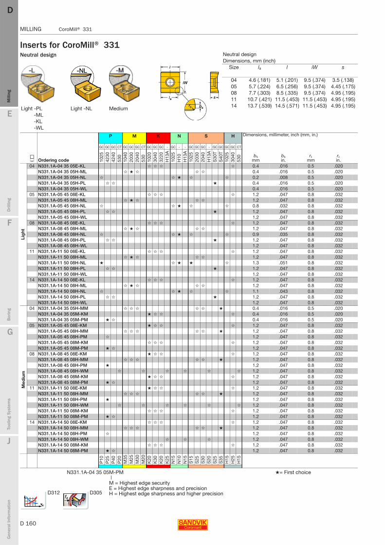
D 160
MILLING CoroMill® 331
E
Mill
ing
Drilli
ng
F
Bor
ing
G
Tool
ing
Syst
ems
J
Gen
eral
Info
rmat
ion
DDM
illin
g
MILLING CoroMill® 331
Inserts for CoroMill® 331Neutral design
Light -PL Light -NL Medium-ML-KL-WL
P M K N S H Dimensions, millimeter, inch (mm, in.)
J Ordering code
GC GC GC CT GC GC GC CT GC GC GC - GC - - GC GC GC - GC GC GC GC CT
bsmm
bsin.
rεmm
rεin.10
2542
3042
4053
010
4020
3020
4053
010
2030
4032
20H
13A
1025
H10
H13
A10
2520
3020
40H
13A
S30
TS
40T
1025
3040
530
Lig
ht
04 N331.1A-04 35 05E-KL ✩ ✩ ✩ ✩ 0.4 .016 0.5 .020N331.1A-04 35 05H-ML ✩ ★ ✩ ✩ ✩ 0.4 .016 0.5 .020N331.1A-04 35 05H-NL ✩ ✩ ★ ✩ ✩ 0.2 .008 0.5 .020N331.1A-04 35 05H-PL ✩ ✩ ★ 0.4 .016 0.5 .020N331.1A-04 35 05H-WL 0.4 .016 0.5 .020
05 N331.1A-05 45 08E-KL ✩ ✩ ✩ ✩ 1.2 .047 0.8 .032N331.1A-05 45 08H-ML ✩ ★ ✩ ✩ ✩ 1.2 .047 0.8 .032N331.1A-05 45 08H-NL ✩ ✩ ★ ✩ ✩ 0.8 .032 0.8 .032N331.1A-05 45 08H-PL ✩ ✩ ★ 1.2 .047 0.8 .032N331.1A-05 45 08H-WL 1.2 .047 0.8 .032
08 N331.1A-08 45 08E-KL ✩ ✩ ✩ ✩ 1.2 .047 0.8 .032N331.1A-08 45 08H-ML ✩ ★ ✩ ✩ ✩ 1.2 .047 0.8 .032N331.1A-08 45 08H-NL ✩ ✩ ★ ✩ ✩ 0.9 .035 0.8 .032N331.1A-08 45 08H-PL ✩ ✩ ★ 1.2 .047 0.8 .032N331.1A-08 45 08H-WL 1.2 .047 0.8 .032
11 N331.1A-11 50 08E-KL ✩ ✩ ✩ ✩ 1.2 .047 0.8 .032N331.1A-11 50 08H-ML ✩ ★ ✩ ✩ ✩ 1.2 .047 0.8 .032N331.1A-11 50 08H-NL ★ ✩ ★ ★ ✩ 1.3 .051 0.8 .032N331.1A-11 50 08H-PL ✩ ✩ ★ 1.2 .047 0.8 .032N331.1A-11 50 08H-WL 1.2 .047 0.8 .032
14 N331.1A-14 50 08E-KL ✩ ✩ ✩ ✩ 1.2 .047 0.8 .032N331.1A-14 50 08H-ML ✩ ★ ✩ ✩ ✩ 1.2 .047 0.8 .032N331.1A-14 50 08H-NL ✩ ✩ ★ ✩ ✩ 1.1 .043 0.8 .032N331.1A-14 50 08H-PL ✩ ✩ ★ 1.2 .047 0.8 .032N331.1A-14 50 08H-WL 1.2 .047 0.8 .032
Med
ium
04 N331.1A-04 35 05H-MM ✩ ✩ ✩ ✩ ✩ ★ 0.4 .016 0.5 .020N331.1A-04 35 05M-KM ★ ✩ ✩ ✩ 0.4 .016 0.5 .020N331.1A-04 35 05M-PM ★ ✩ 0.4 .016 0.5 .020
05 N331.1A-05 45 08E-KM ★ ✩ ✩ ✩ 1.2 .047 0.8 .032N331.1A-05 45 08H-MM ✩ ✩ ✩ ✩ ✩ ★ 1.2 .047 0.8 .032N331.1A-05 45 08H-PM ✩ 1.2 .047 0.8 .032N331.1A-05 45 08M-KM ✩ ✩ ✩ ✩ 1.2 .047 0.8 .032N331.1A-05 45 08M-PM ★ ✩ 1.2 .047 0.8 .032
08 N331.1A-08 45 08E-KM ★ ✩ ✩ ✩ 1.2 .047 0.8 .032N331.1A-08 45 08H-MM ✩ ✩ ✩ ✩ ✩ ★ 1.2 .047 0.8 .032N331.1A-08 45 08H-PM ★ 1.2 .047 0.8 .032N331.1A-08 45 08H-WM ✩ ✩ ✩ ✩ ✩ ✩ 1.2 .047 0.8 .032N331.1A-08 45 08M-KM ★ ✩ ✩ ✩ 1.2 .047 0.8 .032N331.1A-08 45 08M-PM ★ ✩ 1.2 .047 0.8 .032
11 N331.1A-11 50 08E-KM ★ ✩ ✩ ✩ 1.2 .047 0.8 .032N331.1A-11 50 08H-MM ✩ ✩ ✩ ✩ ✩ ★ 1.2 .047 0.8 .032N331.1A-11 50 08H-PM ★ 1.2 .047 0.8 .032N331.1A-11 50 08H-WM ✩ ✩ ✩ ✩ ✩ ✩ 1.2 .047 0.8 .032N331.1A-11 50 08M-KM ✩ ✩ ✩ ✩ 1.2 .047 0.8 .032N331.1A-11 50 08M-PM ★ ✩ 1.2 .047 0.8 .032
14 N331.1A-14 50 08E-KM ✩ ✩ ✩ ✩ 1.2 .047 0.8 .032N331.1A-14 50 08H-MM ✩ ✩ ✩ ✩ ✩ ★ 1.2 .047 0.8 .032N331.1A-14 50 08H-PM ✩ 1.2 .047 0.8 .032N331.1A-14 50 08H-WM ✩ ✩ ✩ 1.2 .047 0.8 .032N331.1A-14 50 08M-KM ✩ ✩ ✩ ✩ 1.2 .047 0.8 .032N331.1A-14 50 08M-PM ★ ✩ 1.2 .047 0.8 .032
P10
P25
P40
P20
M35
M25
M30
M20
K20
K30
K20
K25
N15
N10
N15
S15
S25
S30
S20
S25
S35
H15
H25
H15
N331.1A-04 35 05M-PM ★= First choice|
M = Highest edge securityE = Highest edge sharpness and precisionH = Highest edge sharpness and higher precision
Neutral designDimensions, mm (inch)
Size la l iW s
04 4.6 (.181) 5.1 (.201) 9.5 (.374) 3.5 (.138)05 5.7 (.224) 6.5 (.256) 9.5 (.374) 4.45 (.175)08 7.7 (.303) 8.5 (.335) 9.5 (.374) 4.95 (.195)11 10.7 (.421) 11.5 (.453) 11.5 (.453) 4.95 (.195)14 13.7 (.539) 14.5 (.571) 11.5 (.453) 4.95 (.195)
D312 D305
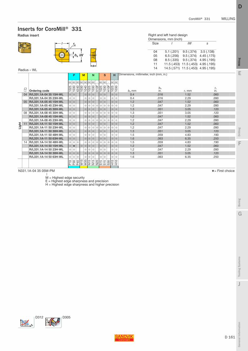
E
D 161
Mill
ing
Drilli
ng
F
Bor
ing
G
Tool
ing
Syst
ems
J
Gen
eral
Info
rmat
ion
DD
Mill
ing
CoroMill® 331 MILLING
MILLING CoroMill® 331
Inserts for CoroMill® 331Radius insert
Radius – WL
P M N S H Dimensions, millimeter, inch (mm, in.)
K Ordering code
GC GC GC GC GC GC GC - GC GC - GC GC
bs mmbsin. rε mm
rεin.10
2510
3042
4010
3010
4010
2510
30H
10F
1025
1030
H10
F10
2510
30
Lig
ht
04 R/L331.1A-04 35 15H-WL ✩ ✩ ✩ ✩ ✩ ✩ ✩ ✩ ✩ 0.4 .016 1.52 .060R/L331.1A-04 35 23H-WL ✩ ✩ ✩ ✩ ✩ ✩ ✩ ✩ ✩ 0.4 .016 2.29 .090
05 R/L331.1A-05 45 15H-WL ✩ ✩ ✩ ✩ ✩ ✩ ✩ ✩ ✩ 1.2 .047 1.52 .060R/L331.1A-05 45 23H-WL ✩ ✩ ✩ ✩ ✩ ✩ ✩ ✩ ✩ ✩ ✩ 1.2 .047 2.29 .090R/L331.1A-05 45 30H-WL ✩ ✩ ✩ ✩ ✩ ✩ ✩ ✩ ✩ 1.3 .051 3.05 .120
08 R/L331.1A-08 45 30H-WL ✩ ✩ ✩ ✩ ✩ ✩ ✩ ✩ ✩ ✩ ✩ 1.3 .051 3.05 .120R/L331.1A-08 45 15H-WL ✩ ✩ ✩ ✩ ✩ ✩ ✩ ✩ ✩ 1.2 .047 1.52 .060R/L331.1A-08 45 23H-WL ✩ ✩ ✩ ✩ ✩ ✩ ✩ ✩ ✩ ✩ ✩ 1.2 .047 2.29 .090
11 R/L331.1A-11 50 15H-WL ✩ ✩ ✩ ✩ ✩ ✩ ✩ ✩ ✩ 1.2 .047 1.52 .060R/L331.1A-11 50 23H-WL ✩ ✩ ✩ ✩ ✩ ✩ ✩ ✩ ✩ ✩ ✩ 1.2 .047 2.29 .090R/L331.1A-11 50 30H-WL ✩ ✩ ✩ ✩ ✩ ✩ ✩ ✩ ✩ 1.3 .051 3.05 .120R/L331.1A-11 50 48H-WL ✩ ✩ ✩ ✩ ✩ ✩ ✩ ✩ ✩ 1.5 .059 4.83 .190R/L331.1A-11 50 63H-WL ✩ ✩ ✩ ✩ ✩ ✩ ✩ ✩ ✩ 1.6 .063 6.35 .250
14 R/L331.1A-14 50 48H-WL ✩ ✩ ✩ ✩ ✩ ✩ ✩ ✩ ✩ ✩ ✩ ✩ 1.5 .059 4.83 .190R/L331.1A-14 50 15H-WL ✩ ★ ✩ ✩ ✩ ✩ ✩ ✩ ✩ ✩ 1.2 .047 1.52 .060R/L331.1A-14 50 23H-WL ✩ ✩ ✩ ✩ ✩ ✩ ✩ ✩ ✩ 1.2 .047 2.29 .090R/L331.1A-14 50 30H-WL ✩ ✩ ✩ ✩ ✩ ✩ ✩ ✩ ✩ ✩ ✩ ✩ 1.3 .051 3.05 .120R/L331.1A-14 50 63H-WL ✩ ✩ ✩ ✩ ✩ ✩ ✩ ✩ ✩ ✩ 1.6 .063 6.35 .250
P10
P30
P40
M15
M35
N15
N15
N20
S15
S15
S30
H15
H10
N331.1A-04 35 05M-PM ★= First choice|M = Highest edge securityE = Highest edge sharpness and precisionH = Highest edge sharpness and higher precision
Right and left hand designDimensions, mm (inch)
Size l iW s
04 5.1 (.201) 9.5 (.374) 3.5 (.138)05 6.5 (.256) 9.5 (.374) 4.45 (.175)08 8.5 (.335) 9.5 (.374) 4.95 (.195)11 11.5 (.453) 11.5 (.453) 4.95 (.195)14 14.5 (.571) 11.5 (.453) 4.95 (.195)
D312 D305
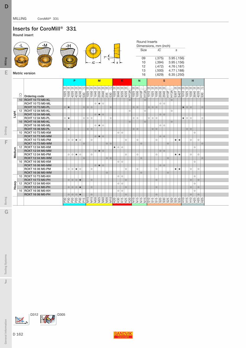
D 162
MILLING CoroMill® 331
E
Mill
ing
Drilli
ng
F
Bor
ing
G
Tool
ing
Syst
ems
J
Gen
eral
Info
rmat
ion
DDM
illin
g
MILLING CoroMill® 331
Inserts for CoroMill® 331Round insert
Metric version
P M K N S H
L Ordering code
GC GC GC GC GC CT GC GC GC GC GC GC CT GC GC GC GC - GC GC - - GC GC GC GC GC - - GC GC GC GC GC GC GC CT
1025
1030
4220
4230
4240
530
1025
1030
1040
2030
2040
235
530
1020
3040
3220
4220
H13
A10
2510
30H
10F
H13
A10
1010
2510
3020
3020
40H
10F
H13
AS
30T
S40
T10
1010
2510
3030
4042
2053
0
Lig
ht
10 RCHT 10 T3 M0-KL ✩ ✩ ✩
RCHT 10 T3 M0-ML ✩ ★ ✩ ✩ ✩
RCHT 10 T3 M0-PL ✩ ★ ✩ ✩ ✩ ✩ ✩ ✩ ✩ ✩ ✩ ★ ✩ ✩ ✩
12 RCHT 12 04 M0-KL ✩ ✩ ✩
RCHT 12 04 M0-ML ✩ ★ ✩ ✩ ✩
RCHT 12 04 M0-PL ✩ ★ ✩ ✩ ✩ ✩ ✩ ✩ ✩ ✩ ✩ ★ ✩ ✩ ✩
16 RCHT 16 06 M0-KL ✩ ✩ ✩
RCHT 16 06 M0-ML ✩ ★ ✩ ✩ ✩
RCHT 16 06 M0-PL ✩ ★ ✩ ✩ ✩ ✩ ✩ ✩ ✩ ✩
Med
ium
10 RCKT 10 T3 M0-KM ✩ ✩ ✩
RCKT 10 T3 M0-MM ✩ ★ ✩ ✩ ✩
RCKT 10 T3 M0-PM ✩ ✩ ★ ✩ ✩ ✩ ✩ ✩ ★ ★ ✩ ✩
RCKT 10 T3 M0-WM ✩ ✩ ✩ ✩ ✩ ✩
12 RCKT 12 04 M0-KM ★ ✩ ✩ ✩
RCKT 12 04 M0-MM ✩ ★ ✩ ✩ ✩
RCKT 12 04 M0-PM ✩ ✩ ★ ✩ ✩ ✩ ✩ ✩ ★ ★ ✩ ✩
RCKT 12 04 M0-WM ✩ ✩ ✩ ✩ ✩ ✩
16 RCKT 16 06 M0-KM ✩ ✩ ✩
RCKT 16 06 M0-MM ✩ ★ ✩ ✩ ✩
RCKT 16 06 M0-PM ✩ ✩ ★ ✩ ✩ ✩ ✩ ✩ ★ ★ ✩ ✩
RCKT 16 06 M0-WM ✩ ✩ ✩
Hea
vy
10 RCKT 10 T3 M0-KH ✩ ✩ ✩
RCKT 10 T3 M0-PH ✩ ✩ ✩ ★ ✩ ✩ ✩ ✩ ✩
12 RCKT 12 04 M0-KH ✩ ✩ ✩
RCKT 12 04 M0-PH ✩ ✩ ✩ ★ ✩ ✩ ✩ ✩ ✩
16 RCKT 16 06 M0-KH ✩ ✩ ✩
RCKT 16 06 M0-PH ✩ ✩ ✩ ★ ✩ ✩ ✩ ✩ ✩
P30
P30
P20
P20
P40
P15
M15
M15
M35
M25
M40
M35
M10
K20
K30
K15
K25
K20
N15
N15
N15
N15
S10
S15
S15
S20
S30
S25
S20
S25
S35
H10
H15
H10
H25
H25
H25
Round InsertsDimensions, mm (inch)
Size iC s
09 (.375) 3.95 (.156)10 (.394) 3.95 (.156)12 (.472) 4.76 (.187)13 (.500) 4.77 (.188)16 (.629) 6.35 (.250)
D312 D305
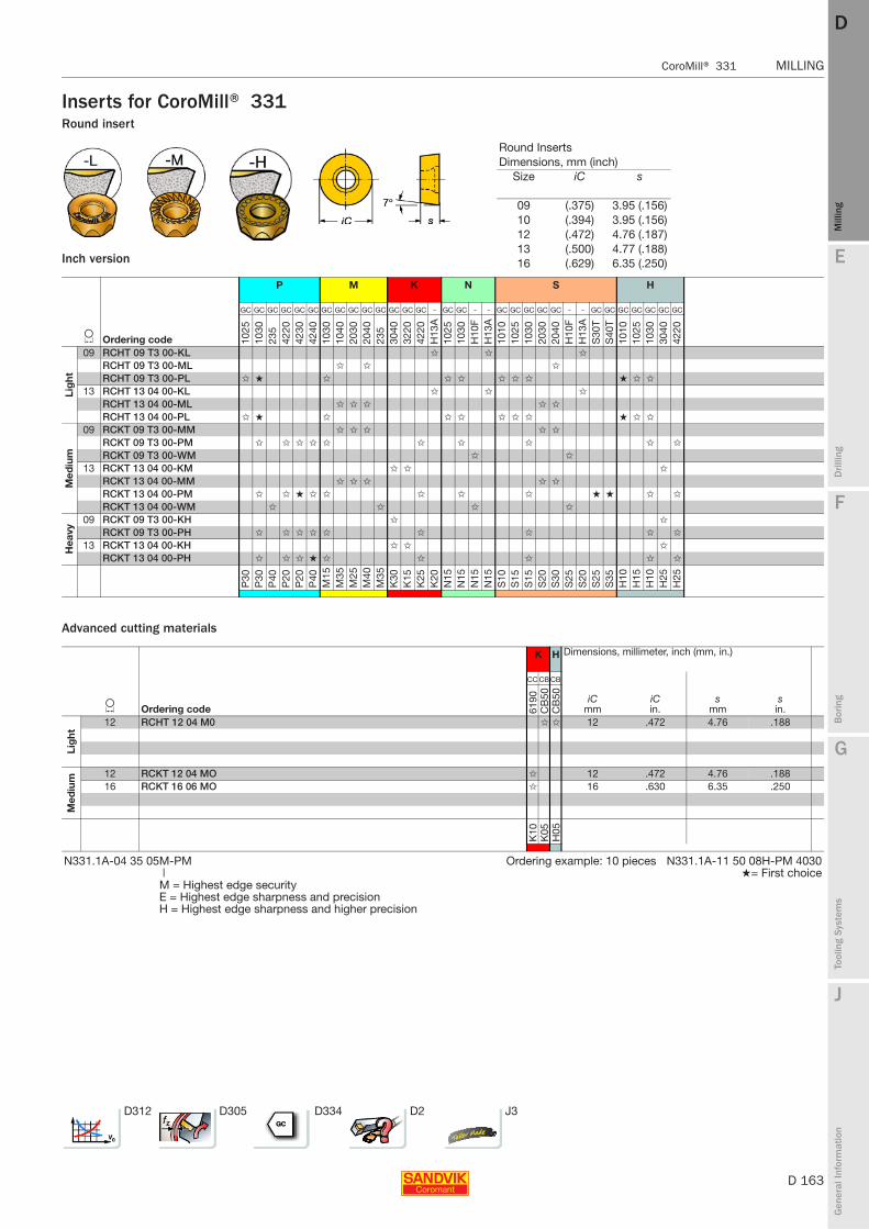
E
D 163
Mill
ing
Drilli
ng
F
Bor
ing
G
Tool
ing
Syst
ems
J
Gen
eral
Info
rmat
ion
DD
Mill
ing
CoroMill® 331 MILLING
MILLING CoroMill® 331
Inserts for CoroMill® 331Round insert
Inch version
Advanced cutting materials
P M K N S H
L Ordering code
GC GC GC GC GC GC GC GC GC GC GC GC GC GC - GC GC - - GC GC GC GC GC - - GC GC GC GC GC GC GC
1025
1030
235
4220
4230
4240
1030
1040
2030
2040
235
3040
3220
4220
H13
A10
2510
30H
10F
H13
A10
1010
2510
3020
3020
40H
10F
H13
AS
30T
S40
T10
1010
2510
3030
4042
20
Lig
ht
09 RCHT 09 T3 00-KL ✩ ✩ ✩
RCHT 09 T3 00-ML ✩ ✩ ✩
RCHT 09 T3 00-PL ✩ ★ ✩ ✩ ✩ ✩ ✩ ✩ ★ ✩ ✩
13 RCHT 13 04 00-KL ✩ ✩ ✩
RCHT 13 04 00-ML ✩ ✩ ✩ ✩ ✩
RCHT 13 04 00-PL ✩ ★ ✩ ✩ ✩ ✩ ✩ ✩ ★ ✩ ✩
Med
ium
09 RCKT 09 T3 00-MM ✩ ✩ ✩ ✩ ✩
RCKT 09 T3 00-PM ✩ ✩ ✩ ✩ ✩ ✩ ✩ ✩ ✩ ✩
RCKT 09 T3 00-WM ✩ ✩
13 RCKT 13 04 00-KM ✩ ✩ ✩
RCKT 13 04 00-MM ✩ ✩ ✩ ✩ ✩
RCKT 13 04 00-PM ✩ ✩ ★ ✩ ✩ ✩ ✩ ✩ ★ ★ ✩ ✩
RCKT 13 04 00-WM ✩ ✩ ✩ ✩
Hea
vy
09 RCKT 09 T3 00-KH ✩ ✩
RCKT 09 T3 00-PH ✩ ✩ ✩ ✩ ✩ ✩ ✩ ✩ ✩
13 RCKT 13 04 00-KH ✩ ✩ ✩
RCKT 13 04 00-PH ✩ ✩ ✩ ★ ✩ ✩ ✩ ✩ ✩
P30
P30
P40
P20
P20
P40
M15
M35
M25
M40
M35
K30
K15
K25
K20
N15
N15
N15
N15
S10
S15
S15
S20
S30
S25
S20
S25
S35
H10
H15
H10
H25
H25
K H Dimensions, millimeter, inch (mm, in.)
L Ordering code
CC CB CB
iCmm
iCin.
smm
sin.61
90C
B50
CB
50
Lig
ht
12 RCHT 12 04 M0 ✩ ✩ 12 .472 4.76 .188
Med
ium 12 RCKT 12 04 MO ✩ 12 .472 4.76 .188
16 RCKT 16 06 MO ✩ 16 .630 6.35 .250
K10
K05
H05
N331.1A-04 35 05M-PM Ordering example: 10 pieces N331.1A-11 50 08H-PM 4030| ★= First choiceM = Highest edge securityE = Highest edge sharpness and precisionH = Highest edge sharpness and higher precision
D312 D305 D334 D2 J3
Round InsertsDimensions, mm (inch)
Size iC s
09 (.375) 3.95 (.156)10 (.394) 3.95 (.156)12 (.472) 4.76 (.187)13 (.500) 4.77 (.188)16 (.629) 6.35 (.250)

D 164
MILLING CoroMill® 331
E
Mill
ing
Drilli
ng
F
Bor
ing
G
Tool
ing
Syst
ems
J
Gen
eral
Info
rmat
ion
DDM
illin
g
MILLING CoroMill® 331
Inserts for CoroMill® 331
8 cutting edges
Spare parts
Medium
P K Dimensions, millimeter, inch (mm, in.)
J Ordering code
GC GC GC GC GC GC GC GC
bs mmbsin. rε mm
rεin.10
3042
2042
3042
4010
2010
3030
4042
20
Med
ium
13 N331.1D-136508E-PM ✩ ✩ ✩ ★ ★ ✩ ✩ ✩ 1.2 .047 0.8 .032N331.1D-136520E-PM ✩ ✩ ✩ ★ ★ ✩ ✩ ✩ 1.2 .047 2.0 .079
P30
P15
P25
P40
K20
K30
K25
N331.1A-04 35 05M-PM ★= First choice|M = Highest edge securityE = Highest edge sharpness and precisionH = Highest edge sharpness and higher precision
8-edge insert type
Cutter type 1 1 2 3 4 5 6
Cassette RightCassette Left Screw Key (Torx Plus) Torque wrench1) Wedge Screw Key (mm)
QM 5321 260-01 5321 260-02 5513 020-25 5680 046-02 (15IP) 5680 100-06 5431 105-05 339-831 265.2-817 (3.0)RM 5321 260-01 5321 260-02 5513 020-25 5680 046-02 (15IP) 5680 100-06 5431 105-05 339-831 265.2-817 (3.0)1) Optional part to be ordered separately.
Note!Cutter bodies can be ordered separately. For further information contact your Sandvik Coromant sales representative.
Note that the diameter of the cutter increases by 3.2 mm when using the new 8 cutting edge cassettes.
D312 D305

E
D 165
Mill
ing
Drilli
ng
F
Bor
ing
G
Tool
ing
Syst
ems
J
Gen
eral
Info
rmat
ion
DD
Mill
ing
CoroMill® 331 MILLING
MILLING CoroMill® 331
Spare parts for CoroMill® 331
R331.32, R331.35, N331.32, Full side and face mill
R/L331.52, Half side and face mill and R/N331.52, Double half side and face mill
N331.32, R331.32, Full side and face mill for round inserts
R331.35, N331.35 Fixed pocket
Cutter type 1 2 3 4 5 6
Cassette Right Left Insert screw Key (Torx Plus) Torque wrench4) Wedge Screw Key (mm)CM/CMX 5321 240-15 5321 240-16 5513 020-19 5680 046-03 (7IP) 5680 100-02 5431 105-07 5516 014-06 5680 048-02 (10IP)DM/DMX 5321 240-13 5321 240-14 5513 020-34 5680 046-01 (8IP) 5680 100-03 5431 105-06 5516 014-041) 5680 048-01 (15IP)EM/EMX 5321 240-01 5321 240-02 5513 020-24 5680 046-04 (9IP) 5680 100-04 5431 105-01 339-8312) 265.2-817 (3.0)FM/FMX 5321 240-03 5321 240-04 5513 020-24 5680 046-04 (9IP) 5680 100-04 5431 105-02 339-8312) 265.2-817 (3.0)KM/KMX 5321 240-07 5321 240-08 5513 020-29 5680 046-02 (15IP) 5680 100-06 5431 105-04 339-8313) 265.2-817 (3.0)LM/LMX 5321 240-07 5321 240-08 5513 020-29 5680 046-02 (15IP) 5680 100-06 5431 105-04 339-831 265.2-817 (3.0)QM/QMX 5321 240-09 5321 240-10 5513 020-29 5680 046-02 (15IP) 5680 100-06 5431 105-05 339-831 265.2-817 (3.0)RM/RMX 5321 240-09 5321 240-10 5513 020-29 5680 046-02 (15IP) 5680 100-06 5431 105-05 339-831 265.2-817 (3.0)1) For cutters N331.32-080S27DM/DMX and R331.32-080Q27DM/DMX, use screw 5516 014-05. Ordering example: 10 pieces 5321 240-152) For cutters N331.32-080S27EM/EMX/FM/FMX and R331.32-080Q27EM/EMX/FM/FMX, use screw 269-832.3) For cutter N331.32-100S32KM/KMX, use screw 5516 010-02.
Cutter type 1 2 3 4 5 6 7
Cassette Right Left Insert screw Key (Torx Plus) Torque wrench4) Wedge Screw Key (mm) Cover3)
EM, EMR/L 5321 240-01 5321 240-02 5513 020-24 5680 046-04 (9IP) 5680 100-04 5431 105-01 339-8311) 265.2-817 (3.0) 5321 240-11FM, FMR/L 5321 240-03 5321 240-04 5513 020-24 5680 046-04 (9IP) 5680 100-04 5431 105-02 339-8311) 265.2-817 (3.0) 5321 240-11KM, KMR/L 5321 240-07 5321 240-08 5513 020-29 5680 046-02 5680 100-06 5431 105-04 339-8312) 265.2-817 (3.0) 5321 240-12MM, MMR/L 5321 240-05 5321 240-06 5513 020-29 5680 046-02 5680 100-06 5431 105-03 339-831 265.2-817 (3.0) 5321 240-12NM, NMR/L 5321 240-07 5321 240-08 5513 020-29 5680 046-02 5680 100-06 5431 105-04 339-831 265.2-817 (3.0) 5321 240-121) For cutters R/L331.52-080S27EM/FM and R/L331.52-080Q27EM/FM, use screw 269-832. Ordering example: 10 pieces 5321 240-012) For cutter R/L331.52-100S32KM, use screw 5516 010-02.3) Only for Half side and face mill cutter
Cutter type 1 2 3 4 5 6
Insert size draw Cassette Neutral Insert screw Key (Torx Plus) Torque wrench4) Wedge Screw Key (mm)EMQ 10 5321 250-02 5513 020-09 5680 046-02 (15IP) 5680 100-06 5431 105-01 339-8311) 265.2-817 (3.0)FMQ 12 5321 250-03 5513 020-09 5680 046-02 (15IP) 5680 100-06 5431 105-02 339-8311) 265.2-817 (3.0)KMQ 16 5321 250-05 5513 020-07 5680 046-06 (20IP) 5680 100-07 5431 105-04 339-8312) 265.2-817 (3.0)1) For cutters N331.32-080S27EMQ/FMQ and R331.32-080Q27EMQ/FMQ, use screw 269-832. Ordering example: 10 pieces 5321 240-022) For cutter N331.32-100S32KMQ, use screw 5516 010-02.
Insert size 2 3
Insert screw Key (Torx Plus) Torque wrench4)
04 5513 020-19 5680 046-03 (7IP) 5680 100-0205 5513 020-34 5680 046-01 (8IP) 5680 100-0308 5513 020-24 5680 046-04 (9IP) 5680 100-044) To be ordered separately.
Fixed pocket
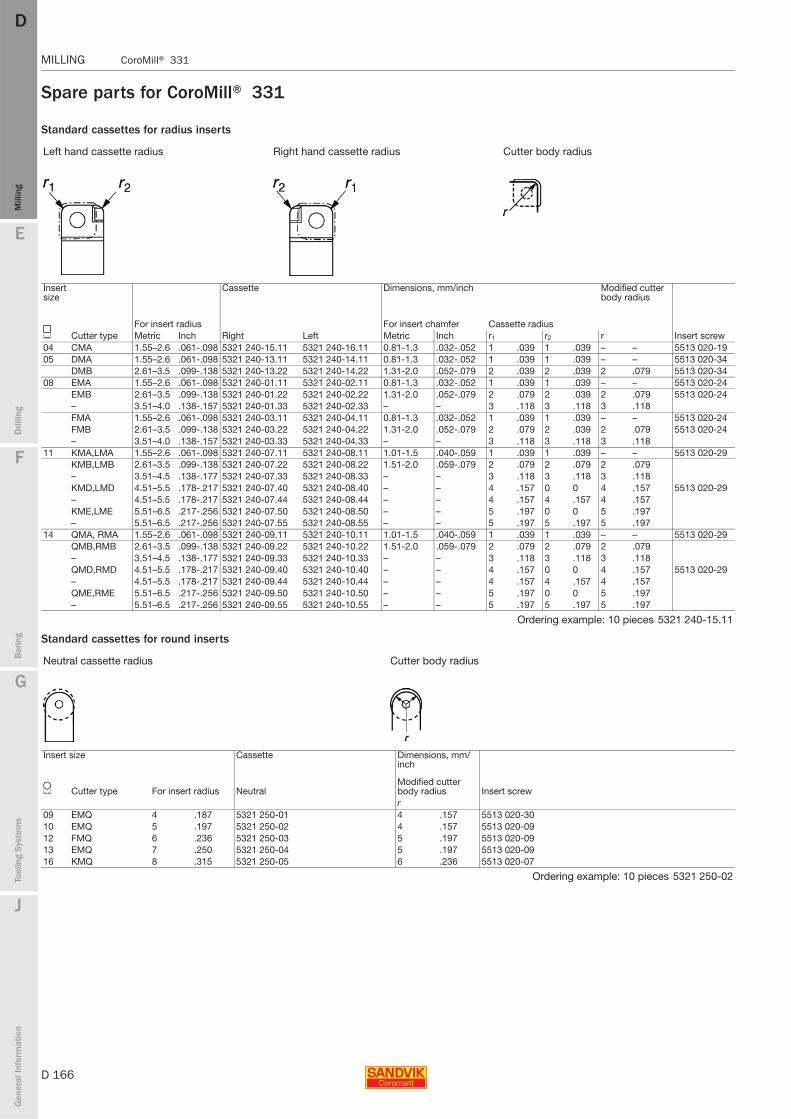
D 166
MILLING CoroMill® 331
E
Mill
ing
Drilli
ng
F
Bor
ing
G
Tool
ing
Syst
ems
J
Gen
eral
Info
rmat
ion
DDM
illin
g
MILLING CoroMill® 331
Spare parts for CoroMill® 331
Standard cassettes for radius inserts
Standard cassettes for round inserts
Left hand cassette radius Right hand cassette radius Cutter body radius
Insert size
Cassette Dimensions, mm/inch Modified cutter body radius
J Cutter typeFor insert radius
Right LeftFor insert chamfer Cassette radius
Insert screwMetric Inch Metric Inch r1 r2 r04 CMA 1.55–2.6 .061-.098 5321 240-15.11 5321 240-16.11 0.81-1.3 .032-.052 1 .039 1 .039 – – 5513 020-1905 DMA 1.55–2.6 .061-.098 5321 240-13.11 5321 240-14.11 0.81-1.3 .032-.052 1 .039 1 .039 – – 5513 020-34
DMB 2.61–3.5 .099-.138 5321 240-13.22 5321 240-14.22 1.31-2.0 .052-.079 2 .039 2 .039 2 .079 5513 020-3408 EMA 1.55–2.6 .061-.098 5321 240-01.11 5321 240-02.11 0.81-1.3 .032-.052 1 .039 1 .039 – – 5513 020-24
EMB 2.61–3.5 .099-.138 5321 240-01.22 5321 240-02.22 1.31-2.0 .052-.079 2 .079 2 .039 2 .079 5513 020-24– 3.51–4.0 .138-.157 5321 240-01.33 5321 240-02.33 – – 3 .118 3 .118 3 .118FMA 1.55–2.6 .061-.098 5321 240-03.11 5321 240-04.11 0.81-1.3 .032-.052 1 .039 1 .039 – – 5513 020-24FMB 2.61–3.5 .099-.138 5321 240-03.22 5321 240-04.22 1.31-2.0 .052-.079 2 .079 2 .039 2 .079 5513 020-24– 3.51–4.0 .138-.157 5321 240-03.33 5321 240-04.33 – – 3 .118 3 .118 3 .118
11 KMA,LMA 1.55–2.6 .061-.098 5321 240-07.11 5321 240-08.11 1.01-1.5 .040-.059 1 .039 1 .039 – – 5513 020-29KMB,LMB 2.61–3.5 .099-.138 5321 240-07.22 5321 240-08.22 1.51-2.0 .059-.079 2 .079 2 .079 2 .079– 3.51–4.5 .138-.177 5321 240-07.33 5321 240-08.33 – – 3 .118 3 .118 3 .118KMD,LMD 4.51–5.5 .178-.217 5321 240-07.40 5321 240-08.40 – – 4 .157 0 0 4 .157 5513 020-29– 4.51–5.5 .178-.217 5321 240-07.44 5321 240-08.44 – – 4 .157 4 .157 4 .157KME,LME 5.51–6.5 .217-.256 5321 240-07.50 5321 240-08.50 – – 5 .197 0 0 5 .197– 5.51–6.5 .217-.256 5321 240-07.55 5321 240-08.55 – – 5 .197 5 .197 5 .197
14 QMA, RMA 1.55–2.6 .061-.098 5321 240-09.11 5321 240-10.11 1.01-1.5 .040-.059 1 .039 1 .039 – – 5513 020-29QMB,RMB 2.61–3.5 .099-.138 5321 240-09.22 5321 240-10.22 1.51-2.0 .059-.079 2 .079 2 .079 2 .079– 3.51–4.5 .138-.177 5321 240-09.33 5321 240-10.33 – – 3 .118 3 .118 3 .118QMD,RMD 4.51–5.5 .178-.217 5321 240-09.40 5321 240-10.40 – – 4 .157 0 0 4 .157 5513 020-29– 4.51–5.5 .178-.217 5321 240-09.44 5321 240-10.44 – – 4 .157 4 .157 4 .157QME,RME 5.51–6.5 .217-.256 5321 240-09.50 5321 240-10.50 – – 5 .197 0 0 5 .197– 5.51–6.5 .217-.256 5321 240-09.55 5321 240-10.55 – – 5 .197 5 .197 5 .197
Ordering example: 10 pieces 5321 240-15.11
Neutral cassette radius Cutter body radius
Insert size Cassette Dimensions, mm/inch
L Cutter type For insert radius NeutralModified cutter body radius Insert screwr
09 EMQ 4 .187 5321 250-01 4 .157 5513 020-3010 EMQ 5 .197 5321 250-02 4 .157 5513 020-0912 FMQ 6 .236 5321 250-03 5 .197 5513 020-0913 EMQ 7 .250 5321 250-04 5 .197 5513 020-0916 KMQ 8 .315 5321 250-05 6 .236 5513 020-07
Ordering example: 10 pieces 5321 250-02
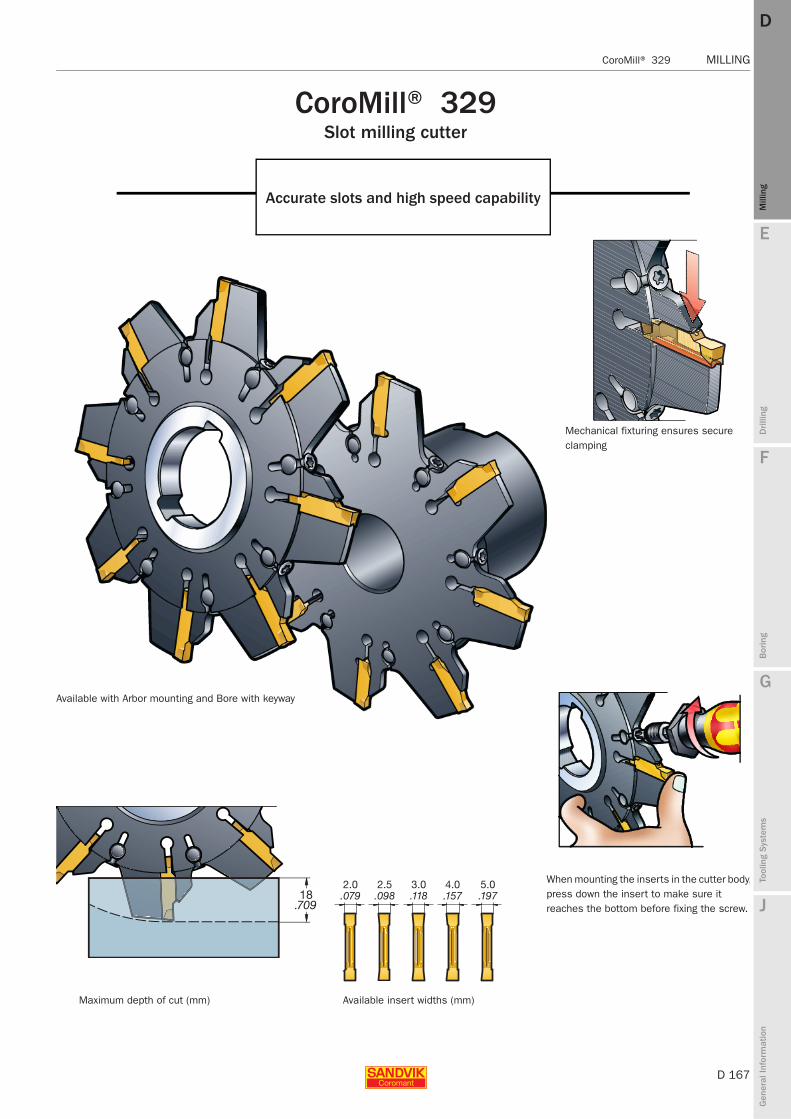
E
D 167
Mill
ing
Drilli
ng
F
Bor
ing
G
Tool
ing
Syst
ems
J
Gen
eral
Info
rmat
ion
DD
Mill
ing
CoroMill® 329 MILLING
MILLING CoroMill® 329
CoroMill® 329Slot milling cutter
Accurate slots and high speed capability
When mounting the inserts in the cutter body,press down the insert to make sure it reaches the bottom before fixing the screw.
Mechanical fixturing ensures secure clamping
Available with Arbor mounting and Bore with keyway
Available insert widths (mm)Maximum depth of cut (mm)

D 168
MILLING CoroMill® 329
E
Mill
ing
Drilli
ng
F
Bor
ing
G
Tool
ing
Syst
ems
J
Gen
eral
Info
rmat
ion
DDM
illin
g
MILLING CoroMill® 329
Grooving cutterDiameter 100 - 160 mmPositive geometry
Metric version
Bore with keyway Arbor
Dimensions, mm
Dc mm Ordering code V Seat size1) b ar dmm D4 l1 E BKW nmax2)
Arbor100 329-100Q22-E 0.66 E 6 15 22 43 50 10.4 4700
329-100Q22-F 1.10 F 6 15 22 42 50 10.4 4400329-100Q22-G 1.05 G 6 15 22 42 50 10.4 4300329-100Q22-H 1.04 H 6 15 22 42 50 10.4 3600329-100Q22-J 1.09 J 6 15 22 43 50 10.4 3350
125 329-125Q32-E 1.70 E 9 18 32 60 63 14.4 4100329-125Q32-F 1.76 F 9 18 32 60 63 14.4 3800329-125Q32-G 1.77 G 8 18 32 60 63 14.4 3700329-125Q32-H 1.78 H 8 18 32 63 63 14.4 3150329-125Q32-J 1.82 J 7 18 32 63 63 14.4 2900
160 329-160Q40-G 2.06 G 11 18 40 72 63 16.4 3300Bore with 1 keyway
100 329-100S22-E 1.11 E 6 15 22 6 10 14.4 4700329-100S22-F 0.57 F 6 15 22 6.25 10 14.4 4400329-100S22-G 0.57 G 6 15 22 6.5 10 14.4 4300329-100S22-H 0.57 H 6 15 22 7 10 14.4 3600329-100S22-J 0.59 J 6 15 22 7.5 10 14.4 3350Bore with 2 keyways
125 329-125S32-E 0.67 E 9 18 32 6 10 8 4100329-125S32-F 0.68 F 9 18 32 6.25 10 8 3800329-125S32-G 0.71 G 8 18 32 6.5 10 8 3700329-125S32-H 0.70 H 8 18 32 7 10 8 3150329-125S32-J 0.73 J 7 18 32 7.5 10 8 2900
160 329-160S40-G 0.97 G 11 18 40 6.5 10 10 33001) To correspond with seat size on insert.2) nmax (max. rev/min) for holders must also be considered.
G6 D170 D169

E
D 169
Mill
ing
Drilli
ng
F
Bor
ing
G
Tool
ing
Syst
ems
J
Gen
eral
Info
rmat
ion
DD
Mill
ing
CoroMill® 329 MILLING
MILLING CoroMill® 329
Grooving cutterDiameter 4.000-5.000 inchPositive geometry
Inch version
Spare parts
Bore with keyway Arbor
Dimensions, inch
Dc inch Ordering code V Seat size1) b ar dmm D4 l1 E BKW nmax2)
Arbor4.000 A329-102R25-E 2.38 E 6 .591 1.000 1.968 1.968 .384 4700
A329-102R25-F 2.51 F 5 .591 1.000 1.968 1.968 .384 4300A329-102R25-G 2.56 G 6 .591 1.000 1.968 1.968 .384 4200A329-102R19-H 2.43 H 6 .591 .750 1.654 1.968 .321 3500A329-102R19-J 2.07 J 6 .591 .750 1.693 1.968 .321 3350
5.000 A329-127R32-E 3.92 E 9 .709 1.250 2.362 2.480 .509 4100A329-127R32-F 3.92 F 9 .709 1.250 2.362 2.480 .567 3700A329-127R32-G 3.96 G 8 .709 1.250 2.362 2.480 .509 3600A329-127R32-H 3.83 H 8 .709 1.250 2.362 2.480 .509 3050A329-127R32-J 4.12 J 7 .709 1.250 2.480 2.480 .509 2900Bore with 1 keyway
4.000 A329-102T25-E 2.23 E 6 .591 1.000 .236 .394 .250 4700A329-102T25-F 1.19 F 6 .591 1.000 .246 .394 .250 4400A329-102T25-G 2.23 G 6 .591 1.000 .256 .394 .250 4300Bore with 2 keyways
5.000 A329-127T38-E 1.50 E 9 .709 1.500 .295 .394 .375 4100A329-127T38-F 1.68 F 9 .709 1.500 .236 .394 .375 3700A329-127T38-G 1.47 G 8 .709 1.500 .246 .394 .375 3600A329-127T32-H 1.46 H 8 .709 1.250 .266 .394 .312 3050
1) To correspond with seat size on insert.2) nmax (max. rev/min) for holders must also be considered.
1 2 3
Torque value
Screw Locking nut Molykote Screwdriver Nm In-lbs5513 017-03 5534 021-02 5683 010-01 5680 046-02 (15IP) 3 26
Note: Always apply Molykote 1000 to screw prior to use.
G6 D170

D 170
MILLING CoroMill® 329
E
Mill
ing
Drilli
ng
F
Bor
ing
G
Tool
ing
Syst
ems
J
Gen
eral
Info
rmat
ion
DDM
illin
g
MILLING CoroMill® 329
Inserts for CoroMill® 329
Tolerances, mm (inch):la = +0.10/0 (+.004/0)rε = ±0.10 (±.004)
For ISO application areas, see bottom of the page.Selection criteria, mm, inch
P M K N S
la rεSeat size1) Ordering code
GC GC GC GC GC CT GC GC GC GC GC - GC GC GC - - GC GC GC GC GC -
1125
1145
2135
3115
4225
525
1005
1105
1125
1145
2135
H13
A11
2531
1542
25H
13A
H13
A10
0511
0511
2511
4521
35H
13A
CoroCut® 2-edge2.00 0.20 E N123E2-0200-0002-CM ✩ ✩ ✩ ✩ ✩ ✩ ✩ ✩ ✩ ✩ ✩ ✩ ✩ ✩ ✩ ✩ ✩
.079 .008 ✩ ✩ ✩ ✩ ✩ ✩ ✩ ✩ ✩ ✩ ✩ ✩ ✩ ✩ ✩ ✩ ✩2.50 0.20 F N123F2-0250-0002-CM ✩ ✩ ✩ ✩ ✩ ✩ ✩ ✩ ✩ ✩ ✩ ✩ ✩ ✩ ✩ ✩
.098 .008 ✩ ✩ ✩ ✩ ✩ ✩ ✩ ✩ ✩ ✩ ✩ ✩ ✩ ✩ ✩ ✩3.00 0.20 G N123G2-0300-0002-CM ✩ ✩ ✩ ✩ ✩ ✩ ✩ ✩ ✩ ✩ ✩ ✩ ✩ ✩ ✩ ✩ ✩
.118 .008 ✩ ✩ ✩ ✩ ✩ ✩ ✩ ✩ ✩ ✩ ✩ ✩ ✩ ✩ ✩ ✩ ✩4.00 0.20 H N123H2-0400-0002-CM ✩ ✩ ✩ ✩ ✩ ✩ ✩ ✩ ✩ ✩ ✩ ✩ ✩ ✩ ✩ ✩ ✩
.157 .008 ✩ ✩ ✩ ✩ ✩ ✩ ✩ ✩ ✩ ✩ ✩ ✩ ✩ ✩ ✩ ✩ ✩5.00 0.20 J N123J2-0500-0002-CM ✩ ✩ ✩ ✩ ✩ ✩ ✩ ✩ ✩ ✩
.197 .008 ✩ ✩ ✩ ✩ ✩ ✩ ✩ ✩ ✩ ✩
For ISO application areas, see bottom of the page.Selection criteria, mm, inch
P M K N S
la rεSeat size1) Ordering code
GC GC GC GC GC CT GC GC GC GC GC - GC GC GC - - GC GC GC GC GC -
1125
1145
2135
3115
4225
525
1005
1105
1125
1145
2135
H13
A11
2531
1542
25H
13A
H13
A10
0511
0511
2511
4521
35H
13A
CoroCut® 2-edge3.00 0.30 G N123G2-0300-0003-TF ✩ ✩ ✩ ✩ ✩ ✩ ✩ ✩ ✩ ✩ ✩ ✩ ✩ ✩ ✩ ✩ ✩ ✩ ✩ ✩ ✩
.118 .012 ✩ ✩ ✩ ✩ ✩ ✩ ✩ ✩ ✩ ✩ ✩ ✩ ✩ ✩ ✩ ✩ ✩ ✩ ✩ ✩ ✩4.00 0.40 H N123H2-0400-0004-TF ✩ ✩ ✩ ✩ ✩ ✩ ✩ ✩ ✩ ✩ ✩ ✩ ✩ ✩ ✩ ✩ ✩ ✩ ✩ ✩ ✩
123-TF .157 .016 ✩ ✩ ✩ ✩ ✩ ✩ ✩ ✩ ✩ ✩ ✩ ✩ ✩ ✩ ✩ ✩ ✩ ✩ ✩ ✩ ✩5.00 0.40 J N123J2-0500-0004-TF ✩ ✩ ✩ ✩ ✩ ✩ ✩ ✩ ✩ ✩ ✩ ✩ ✩ ✩ ✩ ✩ ✩ ✩ ✩ ✩ ✩
.197 .016 ✩ ✩ ✩ ✩ ✩ ✩ ✩ ✩ ✩ ✩ ✩ ✩ ✩ ✩ ✩ ✩ ✩ ✩ ✩ ✩ ✩
1) To correspond with seat size on holder.
Note: For further geometries, see Parting and Grooving chapter in Supplement/catalogue.
D312 D305
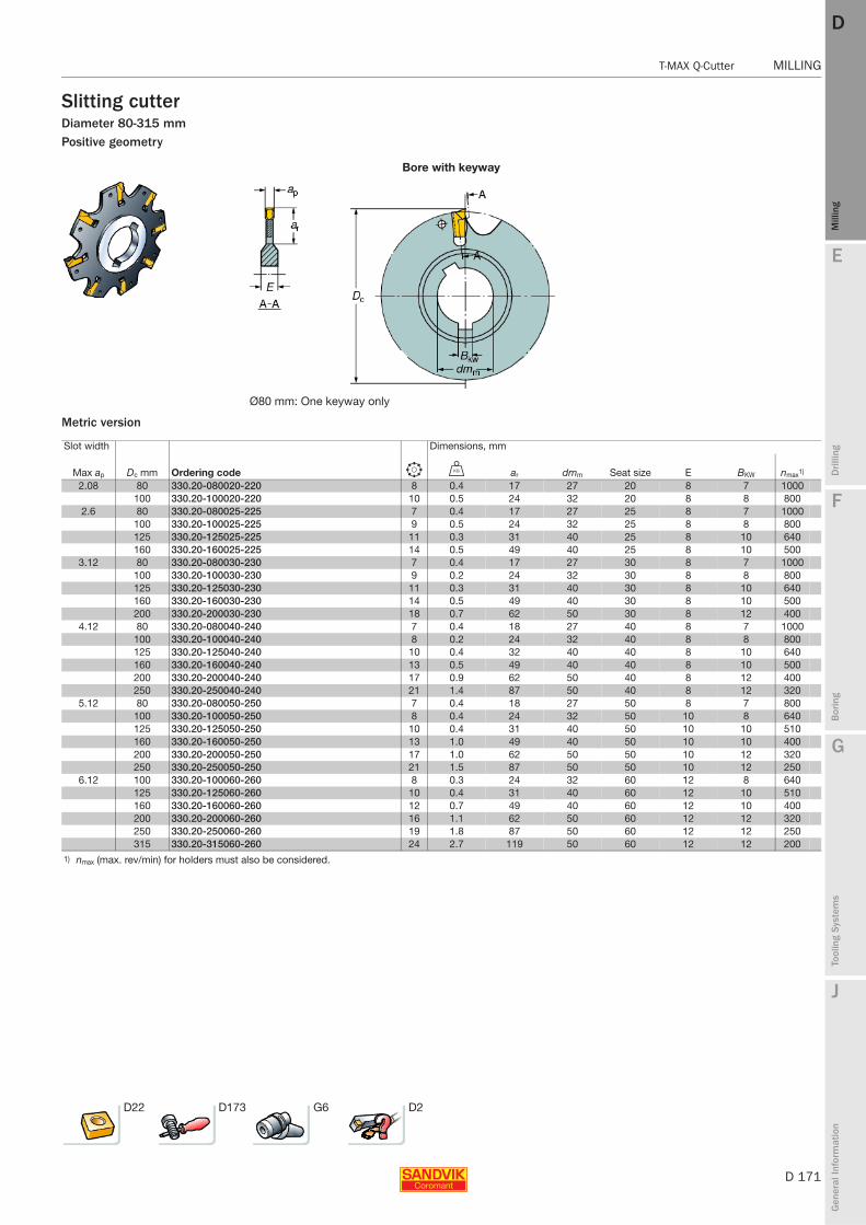
E
D 171
Mill
ing
Drilli
ng
F
Bor
ing
G
Tool
ing
Syst
ems
J
Gen
eral
Info
rmat
ion
DD
Mill
ing
T-MAX Q-Cutter MILLING
MILLING T-MAX Q-Cutter
Slitting cutterDiameter 80-315 mmPositive geometry
Metric version
Bore with keyway
Ø80 mm: One keyway only
Slot width Dimensions, mm
Max ap Dc mm Ordering code b U ar dmm Seat size E BKW nmax1)
2.08 80 330.20-080020-220 8 0.4 17 27 20 8 7 1000100 330.20-100020-220 10 0.5 24 32 20 8 8 800
2.6 80 330.20-080025-225 7 0.4 17 27 25 8 7 1000100 330.20-100025-225 9 0.5 24 32 25 8 8 800125 330.20-125025-225 11 0.3 31 40 25 8 10 640160 330.20-160025-225 14 0.5 49 40 25 8 10 500
3.12 80 330.20-080030-230 7 0.4 17 27 30 8 7 1000100 330.20-100030-230 9 0.2 24 32 30 8 8 800125 330.20-125030-230 11 0.3 31 40 30 8 10 640160 330.20-160030-230 14 0.5 49 40 30 8 10 500200 330.20-200030-230 18 0.7 62 50 30 8 12 400
4.12 80 330.20-080040-240 7 0.4 18 27 40 8 7 1000100 330.20-100040-240 8 0.2 24 32 40 8 8 800125 330.20-125040-240 10 0.4 32 40 40 8 10 640160 330.20-160040-240 13 0.5 49 40 40 8 10 500200 330.20-200040-240 17 0.9 62 50 40 8 12 400250 330.20-250040-240 21 1.4 87 50 40 8 12 320
5.12 80 330.20-080050-250 7 0.4 18 27 50 8 7 800100 330.20-100050-250 8 0.4 24 32 50 10 8 640125 330.20-125050-250 10 0.4 31 40 50 10 10 510160 330.20-160050-250 13 1.0 49 40 50 10 10 400200 330.20-200050-250 17 1.0 62 50 50 10 12 320250 330.20-250050-250 21 1.5 87 50 50 10 12 250
6.12 100 330.20-100060-260 8 0.3 24 32 60 12 8 640125 330.20-125060-260 10 0.4 31 40 60 12 10 510160 330.20-160060-260 12 0.7 49 40 60 12 10 400200 330.20-200060-260 16 1.1 62 50 60 12 12 320250 330.20-250060-260 19 1.8 87 50 60 12 12 250315 330.20-315060-260 24 2.7 119 50 60 12 12 200
1) nmax (max. rev/min) for holders must also be considered.
D22 D173 G6 D2
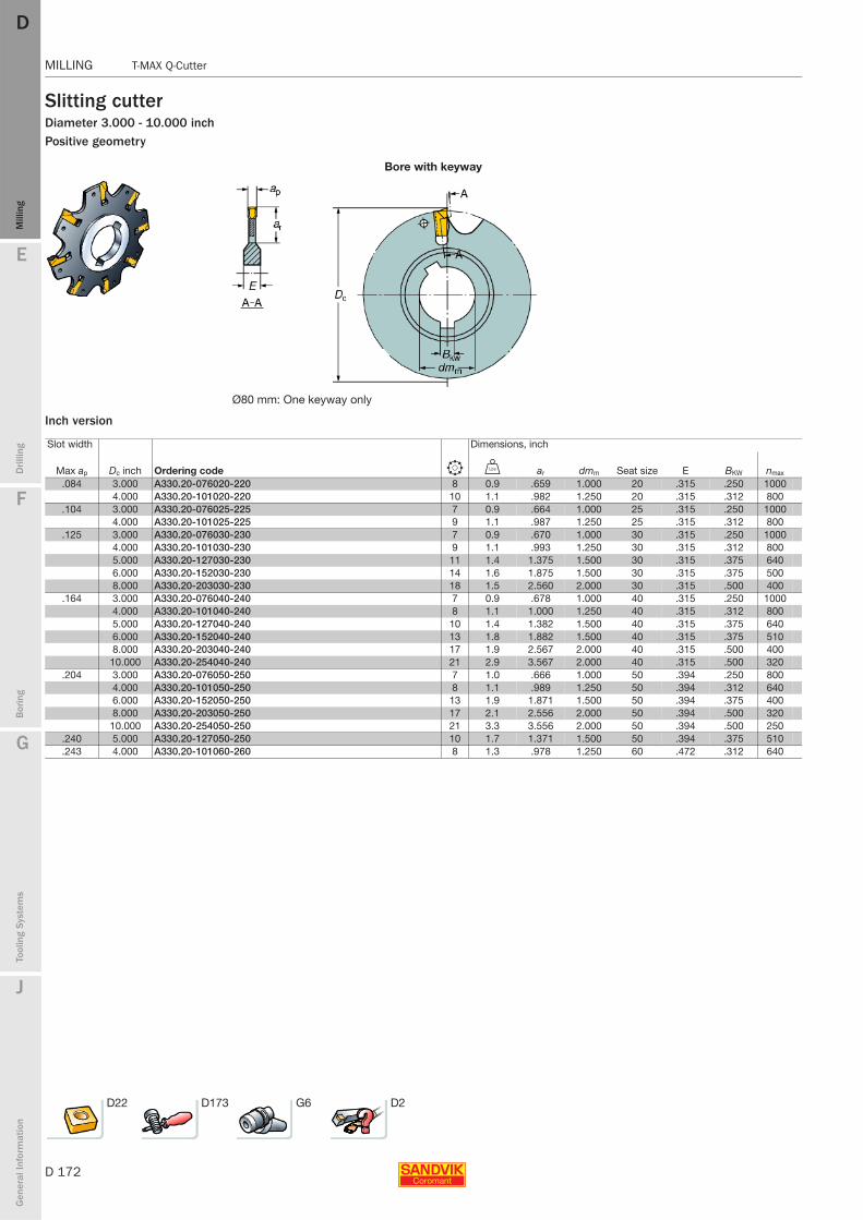
D 172
MILLING T-MAX Q-Cutter
E
Mill
ing
Drilli
ng
F
Bor
ing
G
Tool
ing
Syst
ems
J
Gen
eral
Info
rmat
ion
DDM
illin
g
MILLING T-MAX Q-Cutter
Slitting cutterDiameter 3.000 - 10.000 inchPositive geometry
Inch version
Bore with keyway
Ø80 mm: One keyway only
Slot width Dimensions, inch
Max ap Dc inch Ordering code b V ar dmm Seat size E BKW nmax
.084 3.000 A330.20-076020-220 8 0.9 .659 1.000 20 .315 .250 10004.000 A330.20-101020-220 10 1.1 .982 1.250 20 .315 .312 800
.104 3.000 A330.20-076025-225 7 0.9 .664 1.000 25 .315 .250 10004.000 A330.20-101025-225 9 1.1 .987 1.250 25 .315 .312 800
.125 3.000 A330.20-076030-230 7 0.9 .670 1.000 30 .315 .250 10004.000 A330.20-101030-230 9 1.1 .993 1.250 30 .315 .312 8005.000 A330.20-127030-230 11 1.4 1.375 1.500 30 .315 .375 6406.000 A330.20-152030-230 14 1.6 1.875 1.500 30 .315 .375 5008.000 A330.20-203030-230 18 1.5 2.560 2.000 30 .315 .500 400
.164 3.000 A330.20-076040-240 7 0.9 .678 1.000 40 .315 .250 10004.000 A330.20-101040-240 8 1.1 1.000 1.250 40 .315 .312 8005.000 A330.20-127040-240 10 1.4 1.382 1.500 40 .315 .375 6406.000 A330.20-152040-240 13 1.8 1.882 1.500 40 .315 .375 5108.000 A330.20-203040-240 17 1.9 2.567 2.000 40 .315 .500 400
10.000 A330.20-254040-240 21 2.9 3.567 2.000 40 .315 .500 320.204 3.000 A330.20-076050-250 7 1.0 .666 1.000 50 .394 .250 800
4.000 A330.20-101050-250 8 1.1 .989 1.250 50 .394 .312 6406.000 A330.20-152050-250 13 1.9 1.871 1.500 50 .394 .375 4008.000 A330.20-203050-250 17 2.1 2.556 2.000 50 .394 .500 320
10.000 A330.20-254050-250 21 3.3 3.556 2.000 50 .394 .500 250.240 5.000 A330.20-127050-250 10 1.7 1.371 1.500 50 .394 .375 510.243 4.000 A330.20-101060-260 8 1.3 .978 1.250 60 .472 .312 640
D22 D173 G6 D2
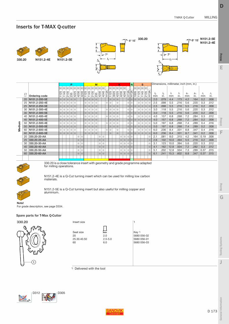
E
D 173
Mill
ing
Drilli
ng
F
Bor
ing
G
Tool
ing
Syst
ems
J
Gen
eral
Info
rmat
ion
DD
Mill
ing
T-MAX Q-Cutter MILLING
MILLING T-MAX Q-Cutter
Inserts for T-MAX Q-cutter
Spare parts for T-Max Q-Cutter
330.20 N151.2-5EN151.2-4E
330.20 N151.2-4E N151.2-5E
P M K N S Dimensions, millimeter, inch (mm, in.)
K Ordering code
GC GC GC GC GC GC GC GC GC GC GC GC GC - GC GC GC GC GC - - GC GC GC GC -
lamm
lain.
l1mm
l1in.
s1mm
s1in.
rεmm
rεin.11
2511
4521
3523
542
2542
3042
4011
2511
4521
3523
542
3042
40H
13A
1125
3020
4225
4230
4240
H13
AH
13A
1005
1125
1145
2135
H13
A
Med
ium
20 N151.2-200-5E ✩ ✩ ✩ ✩ ✩ ✩ ✩ ✩ ✩ ✩ ✩ ✩ ✩ ✩ ✩ ✩ ✩ ✩ ✩ 2.0 .079 4.4 .173 4.2 .164 0.2 .00825 N151.2-250-4E ✩ ✩ ✩ ✩ ✩ ✩ ✩ ✩ ✩ ✩ ✩ ✩ ✩ ✩ ✩ ✩ ✩ ✩ 2.5 .098 5.5 .216 5.6 .220 0.3 .01225 N151.2-250-5E ✩ ✩ ✩ ✩ ✩ ✩ ✩ ✩ ✩ ✩ ✩ ✩ ✩ ✩ ✩ ✩ ✩ ✩ ✩ 2.5 .098 5.5 .216 5.5 .216 0.2 .00830 N151.2-300-4E ✩ ✩ ✩ ✩ ✩ ✩ ✩ ✩ ✩ ✩ ✩ ✩ ✩ ✩ ✩ ✩ ✩ ✩ ✩ 3.0 .118 5.5 .216 5.6 .220 0.3 .01230 N151.2-300-5E ✩ ✩ ✩ ✩ ✩ ✩ ✩ ✩ ✩ ✩ ✩ ✩ ✩ ✩ ✩ ✩ ✩ ✩ ✩ 3.0 .118 5.5 .216 5.6 .220 0.2 .00840 N151.2-400-4E ✩ ✩ ✩ ✩ ✩ ✩ ✩ ✩ ✩ ✩ ✩ ✩ ✩ ✩ ✩ ✩ ✩ ✩ ✩ 4.0 .157 6.8 .268 7.2 .284 0.3 .01240 N151.2-400-5E ✩ ✩ ✩ ✩ ✩ ✩ ✩ ✩ ✩ ✩ ✩ ✩ ✩ ✩ ✩ ✩ ✩ ✩ ✩ 4.0 .157 6.8 .268 7.2 .284 0.2 .00850 N151.2-500-4E ✩ ✩ ✩ ✩ ✩ ✩ ✩ ✩ ✩ ✩ ✩ ✩ ✩ ✩ ✩ ✩ ✩ ✩ ✩ 5.0 .197 6.8 .268 7.4 .289 0.4 .01650 N151.2-500-5E ✩ ✩ ✩ ✩ ✩ ✩ ✩ ✩ ✩ ✩ ✩ ✩ ✩ ✩ ✩ ✩ ✩ ✩ ✩ 5.0 .197 6.8 .268 7.4 .289 0.2 .00860 N151.2-600-4E ✩ ✩ ✩ ✩ ✩ ✩ ✩ ✩ ✩ ✩ ✩ ✩ ✩ ✩ ✩ ✩ ✩ ✩ 6.0 .236 8.4 .331 8.8 .347 0.4 .01660 N151.2-600-5E ✩ ✩ ✩ ✩ ✩ ✩ ✩ ✩ ✩ ✩ ✩ ✩ ✩ ✩ ✩ ✩ ✩ ✩ 6.0 .236 8.4 .331 8.7 .341 0.2 .00820 330.20-20-AA ✩ ✩ ✩ ✩ ✩ ✩ ✩ ✩ ✩ 2.1 .081 8.0 .315 4.2 .164 0.19 .00825 330.20-25-AA ✩ ✩ ✩ ✩ ✩ ✩ ✩ ✩ ✩ 2.6 .102 10.0 .394 5.5 .216 0.2 .00830 330.20-30-AA ✩ ✩ ✩ ✩ ✩ ✩ ✩ ✩ ✩ 3.1 .123 10.0 .394 5.6 .220 0.3 .01240 330.20-40-AA ✩ ✩ ✩ ✩ ✩ ✩ ✩ ✩ ✩ 4.1 .162 12.8 .504 7.2 .282 0.3 .01250 330.20-50-AA ✩ ✩ ✩ ✩ ✩ ✩ ✩ ✩ ✩ 5.1 .202 12.8 .504 7.3 .289 0.37 .01560 330.20-60-AA ✩ ✩ ✩ ✩ ✩ ✩ ✩ ✩ ✩ 6.1 .241 15.3 .602 8.8 .347 0.37 .015
330.20 is a close tolerance insert with geometry and grade programme adapted for milling operations.
N151.2-4E is a Q-Cut turning insert which can be used for milling low carbon materials.
N151.2-5E is a Q-Cut turning insert but also useful for milling copper and aluminium.
Note!For grade description, see page D334.
330.20 Insert size 1
Seat size Key 1)
20 2.0 5680 056-0225.30.40.50 2.5-5.0 5680 056-0160 6.0 5680 056-03
1) Delivered with the tool
D312 D305
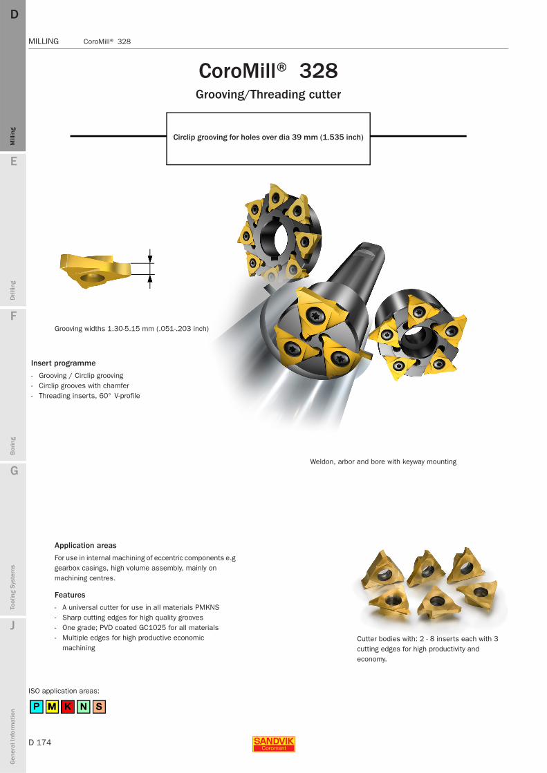
D 174
MILLING CoroMill® 328
E
Mill
ing
Drilli
ng
F
Bor
ing
G
Tool
ing
Syst
ems
J
Gen
eral
Info
rmat
ion
DDM
illin
g
MILLING CoroMill® 328
Grooving widths 1.30-5.15 mm (.051-.203 inch)
Application areas
For use in internal machining of eccentric components e.g gearbox casings, high volume assembly, mainly on machining centres.
Features
- A universal cutter for use in all materials PMKNS- Sharp cutting edges for high quality grooves- One grade; PVD coated GC1025 for all materials- Multiple edges for high productive economic
machiningCutter bodies with: 2 - 8 inserts each with 3 cutting edges for high productivity and economy.
CoroMill® 328Grooving/Threading cutter
Circlip grooving for holes over dia 39 mm (1.535 inch)
ISO application areas:
Weldon, arbor and bore with keyway mounting
Insert programme
- Grooving / Circlip grooving- Circlip grooves with chamfer- Threading inserts, 60° V-profile
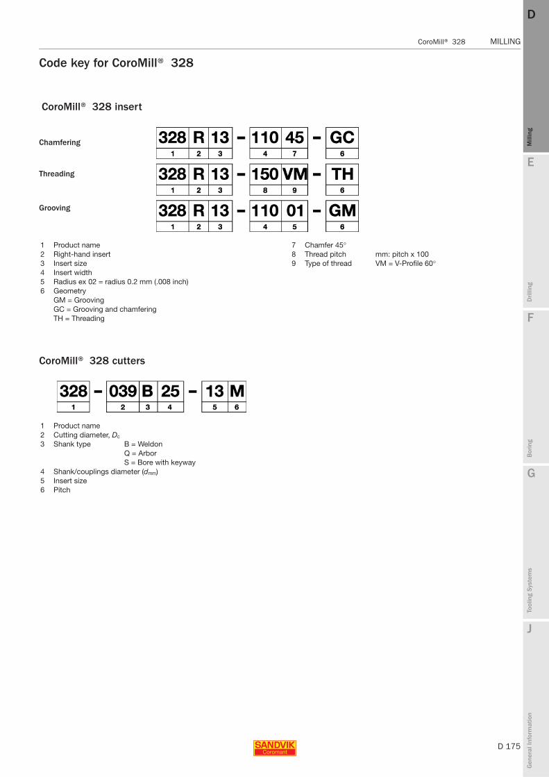
E
D 175
Mill
ing
Drilli
ng
F
Bor
ing
G
Tool
ing
Syst
ems
J
Gen
eral
Info
rmat
ion
DD
Mill
ing
CoroMill® 328 MILLING
MILLING CoroMill® 328
1 Product name 7 Chamfer 45°2 Right-hand insert 8 Thread pitch mm: pitch x 1003 Insert size 9 Type of thread VM = V-Profile 60°4 Insert width5 Radius ex 02 = radius 0.2 mm (.008 inch)6 Geometry
GM = GroovingGC = Grooving and chamferingTH = Threading
Chamfering
Threading
Grooving
CoroMill® 328 cutters
1 Product name2 Cutting diameter, Dc
3 Shank type B = WeldonQ = ArborS = Bore with keyway
4 Shank/couplings diameter (dmm)5 Insert size 6 Pitch
Code key for CoroMill® 328
CoroMill® 328 insert
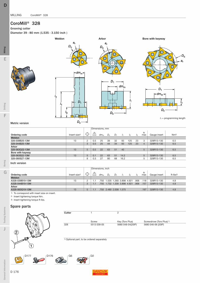
D 176
MILLING CoroMill® 328
E
Mill
ing
Drilli
ng
F
Bor
ing
G
Tool
ing
Syst
ems
J
Gen
eral
Info
rmat
ion
DDM
illin
g
MILLING CoroMill® 328
CoroMill® 328Grooving cutterDiameter 39 - 80 mm (1.535 - 3.150 inch )
Metric version
Inch version
Spare parts
Weldon Arbor Bore with keyway
l1 = programming length
Dimensions, mm
Ordering code Insert size1) e U dmm Dc D1 l1 l2 l3ar
max Gauge insert Nm2)
Weldon328-039B25-13M 13 2 0.5 25 39 32 93 125 23 3 328R13-130 6.5328-044B25-13M 3 0.5 25 44 34 93 125 23 4 328R13-130 6.5Arbor328-063Q22-13M 13 5 0.5 22 63 51 40 5 328R13-130 6.5Bore with keyway328-063S22-13M 13 5 0.1 22 63 51 14.2 5 328R13-130 6.5328-080S27-13M 8 0.3 27 80 68 16.2 5 328R13-130 6.5
Dimensions, inch
Ordering code Insert size1) e V dmm Dc D1 l1 l2 l3ar
max Gauge insert ft-lbs3)
WeldonA328-039B19-13M 13 2 1.1 .750 1.535 1.260 3.898 4.921 .906 .118 328R13-130 4.8A328-044B19-13M 3 1.1 .750 1.732 1.339 3.898 4.921 .906 .157 328R13-130 4.8ArborA328-063Q19-13M 13 5 1.1 .750 2.480 2.008 1.575 .197 328R13-130 4.81) To correspond with insert size on insert.2) Insert tightening torque Nm.3) Insert tightening torque ft-lbs.
Cutter 1 2
Screw Key (Torx Plus) Screwdriver (Torx Plus) 1)
328 5513 039-05 5680 048-04(20IP) 5680 046-06 (20IP)
1) Optional part, to be ordered separately
D177 D176 G6 D2
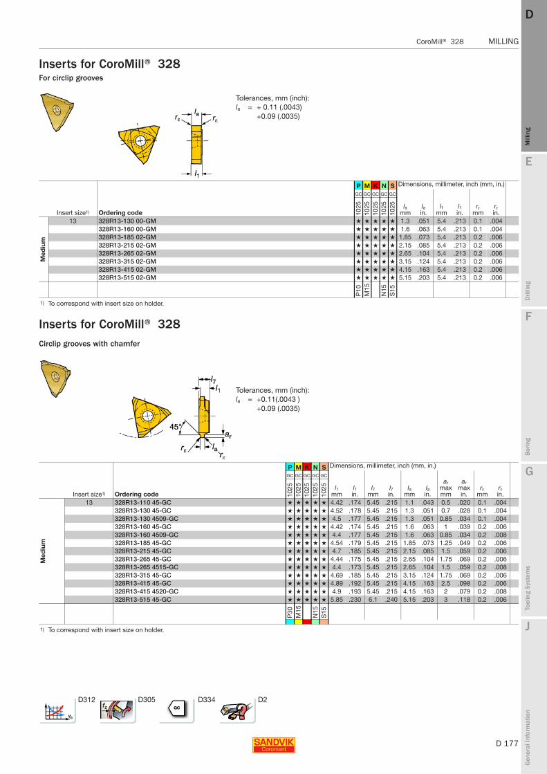
E
D 177
Mill
ing
Drilli
ng
F
Bor
ing
G
Tool
ing
Syst
ems
J
Gen
eral
Info
rmat
ion
DD
Mill
ing
CoroMill® 328 MILLING
MILLING CoroMill® 328
Inserts for CoroMill® 328For circlip grooves
Inserts for CoroMill® 328Circlip grooves with chamfer
P M K N S Dimensions, millimeter, inch (mm, in.)
Insert size1) Ordering code
GC GC GC GC GC
lamm
lain.
l1mm
l1in.
rεmm
rεin.10
2510
2510
2510
2510
25
Med
ium
13 328R13-130 00-GM ★ ★ ★ ★ ★ 1.3 .051 5.4 .213 0.1 .004328R13-160 00-GM ★ ★ ★ ★ ★ 1.6 .063 5.4 .213 0.1 .004328R13-185 02-GM ★ ★ ★ ★ ★ 1.85 .073 5.4 .213 0.2 .006328R13-215 02-GM ★ ★ ★ ★ ★ 2.15 .085 5.4 .213 0.2 .006328R13-265 02-GM ★ ★ ★ ★ ★ 2.65 .104 5.4 .213 0.2 .006328R13-315 02-GM ★ ★ ★ ★ ★ 3.15 .124 5.4 .213 0.2 .006328R13-415 02-GM ★ ★ ★ ★ ★ 4.15 .163 5.4 .213 0.2 .006328R13-515 02-GM ★ ★ ★ ★ ★ 5.15 .203 5.4 .213 0.2 .006
P10
M15
N15
S15
1) To correspond with insert size on holder.
P M K N S Dimensions, millimeter, inch (mm, in.)
Insert size1) Ordering code
GC GC GC GC GC
l1mm
l1in.
l7mm
l7in.
lamm
lain.
ar maxmm
ar maxin.
rεmm
rεin.10
2510
2510
2510
2510
25
Med
ium
13 328R13-110 45-GC ★ ★ ★ ★ ★ 4.42 .174 5.45 .215 1.1 .043 0.5 .020 0.1 .004328R13-130 45-GC ★ ★ ★ ★ ★ 4.52 .178 5.45 .215 1.3 .051 0.7 .028 0.1 .004328R13-130 4509-GC ★ ★ ★ ★ ★ 4.5 .177 5.45 .215 1.3 .051 0.85 .034 0.1 .004328R13-160 45-GC ★ ★ ★ ★ ★ 4.42 .174 5.45 .215 1.6 .063 1 .039 0.2 .006328R13-160 4509-GC ★ ★ ★ ★ ★ 4.4 .177 5.45 .215 1.6 .063 0.85 .034 0.2 .008328R13-185 45-GC ★ ★ ★ ★ ★ 4.54 .179 5.45 .215 1.85 .073 1.25 .049 0.2 .006328R13-215 45-GC ★ ★ ★ ★ ★ 4.7 .185 5.45 .215 2.15 .085 1.5 .059 0.2 .006328R13-265 45-GC ★ ★ ★ ★ ★ 4.44 .175 5.45 .215 2.65 .104 1.75 .069 0.2 .006328R13-265 4515-GC ★ ★ ★ ★ ★ 4.4 .173 5.45 .215 2.65 .104 1.5 .059 0.2 .008328R13-315 45-GC ★ ★ ★ ★ ★ 4.69 .185 5.45 .215 3.15 .124 1.75 .069 0.2 .006328R13-415 45-GC ★ ★ ★ ★ ★ 4.89 .192 5.45 .215 4.15 .163 2.5 .098 0.2 .006328R13-415 4520-GC ★ ★ ★ ★ ★ 4.9 .193 5.45 .215 4.15 .163 2 .079 0.2 .008328R13-515 45-GC ★ ★ ★ ★ ★ 5.85 .230 6.1 .240 5.15 .203 3 .118 0.2 .006
P30
M15
N15
S15
1) To correspond with insert size on holder.
D312 D305 D334 D2
Tolerances, mm (inch):la = + 0.11 (.0043)
+0.09 (.0035)
Tolerances, mm (inch):la = +0.11(.0043 )
+0.09 (.0035)
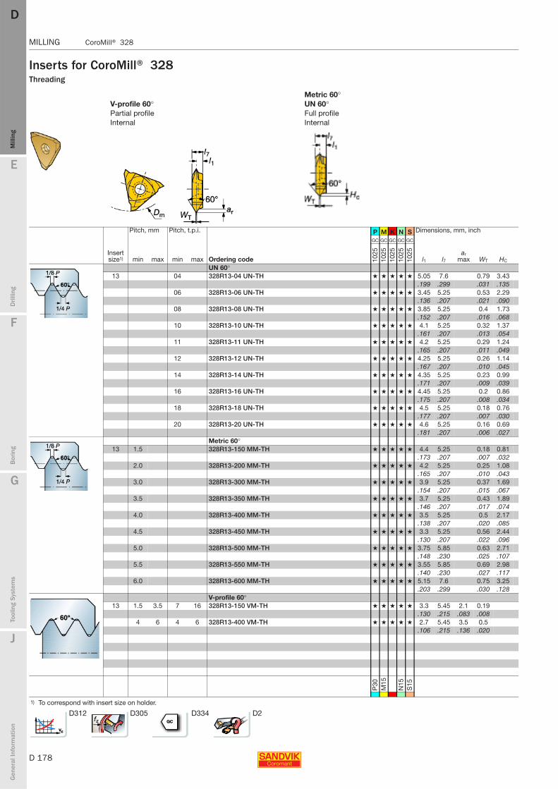
D 178
MILLING CoroMill® 328
E
Mill
ing
Drilli
ng
F
Bor
ing
G
Tool
ing
Syst
ems
J
Gen
eral
Info
rmat
ion
DDM
illin
g
MILLING CoroMill® 328
Inserts for CoroMill® 328Threading
Metric 60°V-profile 60° UN 60°Partial profile Full profileInternal Internal
Pitch, mm Pitch, t.p.i. P M K N S Dimensions, mm, inch
Insert size1) min max min max Ordering code
GC GC GC GC GC
l1 l7ar
max WT HC1025
1025
1025
1025
1025
UN 60°13 04 328R13-04 UN-TH ★ ★ ★ ★ ★ 5.05 7.6 0.79 3.43
.199 .299 .031 .13506 328R13-06 UN-TH ★ ★ ★ ★ ★ 3.45 5.25 0.53 2.29
.136 .207 .021 .09008 328R13-08 UN-TH ★ ★ ★ ★ ★ 3.85 5.25 0.4 1.73
.152 .207 .016 .06810 328R13-10 UN-TH ★ ★ ★ ★ ★ 4.1 5.25 0.32 1.37
.161 .207 .013 .05411 328R13-11 UN-TH ★ ★ ★ ★ ★ 4.2 5.25 0.29 1.24
.165 .207 .011 .04912 328R13-12 UN-TH ★ ★ ★ ★ ★ 4.25 5.25 0.26 1.14
.167 .207 .010 .04514 328R13-14 UN-TH ★ ★ ★ ★ ★ 4.35 5.25 0.23 0.99
.171 .207 .009 .03916 328R13-16 UN-TH ★ ★ ★ ★ ★ 4.45 5.25 0.2 0.86
.175 .207 .008 .03418 328R13-18 UN-TH ★ ★ ★ ★ ★ 4.5 5.25 0.18 0.76
.177 .207 .007 .03020 328R13-20 UN-TH ★ ★ ★ ★ ★ 4.6 5.25 0.16 0.69
.181 .207 .006 .027Metric 60°
13 1.5 328R13-150 MM-TH ★ ★ ★ ★ ★ 4.4 5.25 0.18 0.81.173 .207 .007 .032
2.0 328R13-200 MM-TH ★ ★ ★ ★ ★ 4.2 5.25 0.25 1.08.165 .207 .010 .043
3.0 328R13-300 MM-TH ★ ★ ★ ★ ★ 3.9 5.25 0.37 1.69.154 .207 .015 .067
3.5 328R13-350 MM-TH ★ ★ ★ ★ ★ 3.7 5.25 0.43 1.89.146 .207 .017 .074
4.0 328R13-400 MM-TH ★ ★ ★ ★ ★ 3.5 5.25 0.5 2.17.138 .207 .020 .085
4.5 328R13-450 MM-TH ★ ★ ★ ★ ★ 3.3 5.25 0.56 2.44.130 .207 .022 .096
5.0 328R13-500 MM-TH ★ ★ ★ ★ ★ 3.75 5.85 0.63 2.71.148 .230 .025 .107
5.5 328R13-550 MM-TH ★ ★ ★ ★ ★ 3.55 5.85 0.69 2.98.140 .230 .027 .117
6.0 328R13-600 MM-TH ★ ★ ★ ★ ★ 5.15 7.6 0.75 3.25.203 .299 .030 .128
V-profile 60°13 1.5 3.5 7 16 328R13-150 VM-TH ★ ★ ★ ★ ★ 3.3 5.45 2.1 0.19
.130 .215 .083 .0084 6 4 6 328R13-400 VM-TH ★ ★ ★ ★ ★ 2.7 5.45 3.5 0.5
.106 .215 .136 .020
P30
M15
N15
S15
1) To correspond with insert size on holder.
D312 D305 D334 D2

E
D 179
Mill
ing
Drilli
ng
F
Bor
ing
G
Tool
ing
Syst
ems
J
Gen
eral
Info
rmat
ion
DD
Mill
ing
CoroMill® 327 MILLING
MILLING CoroMill® 327
CoroMill® 327Grooving/Threading cutter
Slot and thread milling for holes over dia. 10 mm
Weldon shank
Steel and carbide shank with different lengths, giving stable set up and higher productivity
Grooving widths 0.7-5.15 mm
Four different sizes of cutter all with three or six cutting edges for high metal removal rate
Application areas
For use in internal machining of eccentric components e.g gearbox casings, high volume assembly, mainly on machining centres.
Features
- A universal cutter for use in all materials PMKNS
- Sharp cutting edges for high quality grooves
- One grade; PVD coated GC1025 for all materials
- Multiple edges for high productive economic machining
Insert programme
- Grooving- Grooving / Full radius- Chamfering- Circlip grooves with chamfer- ThreadingV-Profile 60°Metric 60°Withworth 55° UN 60°
ISO application areas:

D 180
MILLING CoroMill® 327
E
Mill
ing
Drilli
ng
F
Bor
ing
G
Tool
ing
Syst
ems
J
Gen
eral
Info
rmat
ion
DDM
illin
g
MILLING CoroMill® 327
Chamfering
Threading
Profiling
Grooving
1 Product name 8 M = Close pitch2 Right-hand insert 9 Chamfer 45°3 Coupling size (interface) 10 Thread pitch mm: pitch x 1004 Dmin (mm) inch: No. of threads per inch5 Insert width 11 Type of thread VM = V-Profile 60°6 Radius ex 02 = radius 0.2 mm (.008 inch) MM = Metric 60°7 Type of insert GM = Grooving WH = Whitworth 55°
RM = Fullnose radiusCH = ChamferingGC = Grooving and chamferingTH = Threading
CoroMill® 327 holders
1 Product name2 Shank diameter (dmm)3 Shank type B = Weldon
4 Reach length5 Shank materials S = steel
E = solid carbide6 Internal coolant7 Coupling size (interface)
Code key for CoroMill® 327
CoroMill 327 insert

E
D 181
Mill
ing
Drilli
ng
F
Bor
ing
G
Tool
ing
Syst
ems
J
Gen
eral
Info
rmat
ion
DD
Mill
ing
CoroMill® 327 MILLING
MILLING CoroMill® 327
CoroMill® 327Grooving cutter
Tolerance : dmm
Solid carbide : h6Steel shank : g6
Metric version
Inch version
Weldon
l1 = programming length
Dimensions, mm
Insert size1) Ordering code U dmm D1 l1 l2 l3 Gauge insert Nm2)
06 327-12B15SC-06 0.1 12 6 52 74 15 327R06-10 100 00-GM 1.8327-12B21EC-06 0.1 12 6 58 80 21 327R06-10 100 00-GM 1.8327-12B30EC-06 0.1 12 6 68 90 30 327R06-10 100 00-GM 1.8327-12B42EC-06 0.1 12 6 78 100 42 327R06-10 100 00-GM 1.8
09 327-16B18SC-09 0.1 16 9 56 80 18 327R09-18 150 02-GM 4.3327-16B32EC-09 0.2 16 9 76 100 32 327R09-18 150 02-GM 4.3327-16B45EC-09 0.2 16 9 86 110 45 327R09-18 150 02-GM 4.3327-16B64EC-09 0.2 16 9 106 130 64 327R09-18 150 02-GM 4.3
12 327-16B24SC-12 0.1 16 12 56 80 24 327R12-22 150 02-GM 6.5327-16B42EC-12 0.2 16 12 76 100 42 327R12-22 150 02-GM 6.5327-16B60EC-12 0.2 16 12 106 130 60 327R12-22 150 02-GM 6.5327-16B85EC-12 0.3 16 12 136 160 85 327R12-22 150 02-GM 6.5
14 327-16B42EC-14 0.2 16 14.3 76 100 42 327R14-28 150 02-GM 6.5327-16B60EC-14 0.2 16 14.3 106 130 60 327R14-28 150 02-GM 6.5327-16B85EC-14 0.4 16 14.3 136 160 85 327R14-28 150 02-GM 6.5327-20B35SC-14 0.2 20 14.3 75 100 36 327R14-28 150 02-GM 6.5
Dimensions, inch
Insert size1) Ordering code V dmm D1 l1 l2 l3 Gauge insert ft-lbs3)
06 A327-13B21EC-06 0.2 .500 .236 2.264 3.150 .827 327R06-10 100 00-GM 1.3A327-13B30EC-06 0.2 .500 .236 2.658 3.543 1.181 327R06-10 100 00-GM 1.3A327-13B42EC-06 0.2 .500 .236 3.051 3.937 1.654 327R06-10 100 00-GM 1.3
09 A327-16B18SC-09 0.2 .625 .354 2.205 3.150 .709 327R09-18 150 02-GM 3.2A327-16B32EC-09 0.4 .625 .354 2.992 3.937 1.260 327R09-18 150 02-GM 3.2A327-16B45EC-09 0.4 .625 .354 3.386 4.331 1.772 327R09-18 150 02-GM 3.2A327-16B64EC-09 0.4 .625 .354 4.173 5.118 2.520 327R09-18 150 02-GM 3.2
12 A327-16B24SC-12 0.2 .625 .472 2.205 3.150 .945 327R12-22 150 02-GM 4.8A327-16B42EC-12 0.4 .625 .472 2.992 3.937 1.654 327R12-22 150 02-GM 4.8A327-16B60EC-12 0.6 .625 .472 4.173 5.118 2.362 327R12-22 150 02-GM 4.8A327-16B85EC-12 0.7 .625 .472 5.354 6.299 3.346 327R12-22 150 02-GM 4.8
14 A327-16B42EC-14 0.4 .625 .563 2.992 3.937 1.654 327R14-28 150 02-GM 4.8A327-16B60EC-14 0.6 .625 .563 4.173 5.118 2.362 327R14-28 150 02-GM 4.8A327-16B85EC-14 0.7 .625 .563 5.354 6.299 3.346 327R14-28 150 02-GM 4.8
1) To correspond with insert size on insert.2) Insert tightening torque Nm.3) Insert tightening torque ft-lbs.
327-12B42 EC-06|E= Solid carbide shankS=Steel shank
G6 D182 D186

D 182
MILLING CoroMill® 327
E
Mill
ing
Drilli
ng
F
Bor
ing
G
Tool
ing
Syst
ems
J
Gen
eral
Info
rmat
ion
DDM
illin
g
MILLING CoroMill® 327
Inserts for CoroMill® 327Grooving
Number of teeth P M K N S Dimensions, millimeter, inch (mm, in.)
Insert size1) Ordering code z
GC GC GC GC GC
Dcmm
Dcin.
ar maxmm
ar maxin.
lamm
lain.
l1mm
l1in.
rεmm
rεin.10
2510
2510
2510
2510
25
06 327R06-10 10000-GM 3 ★ ★ ★ ★ ★ 9.7 .382 1.5 .059 1.0 .039 3.5 .138327R06-10 15002-GM 3 ★ ★ ★ ★ ★ 9.7 .382 1.5 .059 1.5 .059 3.5 .138 0.2 .008327R06-10 20002-GM 3 ★ ★ ★ ★ ★ 9.7 .382 1.5 .059 2.0 .079 3.5 .138 0.2 .008327R06-10 25002-GM 3 ★ ★ ★ ★ ★ 9.7 .382 1.5 .059 2.5 .098 3.5 .138 0.2 .008
09 327R09-18 15002-GM 3 ★ ★ ★ ★ ★ 17.7 .697 3.5 .138 1.5 .059 5.75 .226 0.2 .008327R09-18 20002-GM 3 ★ ★ ★ ★ ★ 17.7 .697 3.5 .138 2.0 .079 5.75 .226 0.2 .008327R09-18 25002-GM 3 ★ ★ ★ ★ ★ 17.7 .697 3.5 .138 2.5 .098 5.75 .226 0.2 .008327R09-18 30002-GM 3 ★ ★ ★ ★ ★ 17.7 .697 3.5 .138 3.0 .118 5.75 .226 0.2 .008327R09-18 15001-GMM 6 ★ ★ ★ ★ ★ 17.7 .697 3.5 .138 1.5 .059 5.75 .226 0.1 .004327R09-18 20002-GMM 6 ★ ★ ★ ★ ★ 17.7 .697 3.5 .138 2.0 .079 5.75 .226 0.2 .008327R09-18 25002-GMM 6 ★ ★ ★ ★ ★ 17.7 .697 3.5 .138 2.5 .098 5.75 .226 0.2 .008327R09-18 30002-GMM 6 ★ ★ ★ ★ ★ 17.7 .697 3.5 .138 3.0 .118 5.75 .226 0.2 .008
12 327R12-22 15002-GM 3 ★ ★ ★ ★ ★ 21.7 .854 4.5 .177 1.5 .059 5.7 .224 0.2 .008327R12-22 20002-GM 3 ★ ★ ★ ★ ★ 21.7 .854 4.5 .177 2.0 .079 5.7 .224 0.2 .008327R12-22 25002-GM 3 ★ ★ ★ ★ ★ 21.7 .854 4.5 .177 2.5 .098 5.7 .224 0.2 .008327R12-22 30002-GM 3 ★ ★ ★ ★ ★ 21.7 .854 4.5 .177 3.0 .118 5.7 .224 0.2 .008327R12-22 40002-GM 3 ★ ★ ★ ★ ★ 21.7 .854 4.5 .177 4.0 .157 5.7 .224 0.2 .008327R12-28 15001-GMM 6 ★ ★ ★ ★ ★ 27.7 1.091 6.5 .256 1.5 .059 6.2 .244 0.1 .004327R12-28 20002-GMM 6 ★ ★ ★ ★ ★ 27.7 1.091 6.5 .256 2.0 .079 6.2 .244 0.2 .008327R12-28 25002-GMM 6 ★ ★ ★ ★ ★ 27.7 1.091 6.5 .256 2.5 .098 6.2 .244 0.2 .008327R12-28 30002-GMM 6 ★ ★ ★ ★ ★ 27.7 1.091 6.5 .256 3.0 .118 6.25 .246 0.2 .008327R12-28 40002-GMM 6 ★ ★ ★ ★ ★ 27.7 1.091 6.5 .256 4.0 .157 6.25 .246 0.2 .008
14 327R14-28 15000-GM 3 ★ ★ ★ ★ ★ 27.7 1.091 6.5 .256 1.5 .059 6.5 .256 0.2 .008327R14-28 20002-GM 3 ★ ★ ★ ★ ★ 27.7 1.091 6.5 .256 2.0 .079 6.5 .256 0.2 .008327R14-28 25002-GM 3 ★ ★ ★ ★ ★ 27.7 1.091 6.5 .256 2.5 .098 6.5 .256 0.2 .008327R14-28 30002-GM 3 ★ ★ ★ ★ ★ 27.7 1.091 6.5 .256 3.0 .118 6.5 .256 0.2 .008327R14-28 35002-GM 3 ★ ★ ★ ★ ★ 27.7 1.091 6.5 .256 3.5 .138 6.5 .256 0.2 .008327R14-28 40002-GM 3 ★ ★ ★ ★ ★ 27.7 1.091 6.5 .256 4.0 .157 6.5 .256 0.2 .008327R14-35 15001-GMM 6 ★ ★ ★ ★ ★ 34.7 1.366 10.0 .394 1.5 .059 6.25 .246 0.1 .004327R14-35 20002-GMM 6 ★ ★ ★ ★ ★ 34.7 1.366 10.0 .394 2.0 .079 6.25 .246 0.2 .008327R14-35 25002-GMM 6 ★ ★ ★ ★ ★ 34.7 1.366 10.0 .394 2.5 .098 6.25 .246 0.2 .008327R14-35 30002-GMM 6 ★ ★ ★ ★ ★ 34.7 1.366 10.0 .394 3.0 .118 6.25 .246 0.2 .008
P30
M15
N15
S15
1) To correspond with insert size on holder.
D312 D305 D334 D2
Tolerances, mm (inch):la = +0.02 (.0008)

E
D 183
Mill
ing
Drilli
ng
F
Bor
ing
G
Tool
ing
Syst
ems
J
Gen
eral
Info
rmat
ion
DD
Mill
ing
CoroMill® 327 MILLING
MILLING CoroMill® 327
Inserts for CoroMill® 327Grooving For circlip grooves
Number of teeth P M K N S Dimensions, millimeter, inch (mm, in.)
Insert size1) Ordering code z
GC GC GC GC GC
Dcmm
Dcin.
ar maxmm
ar maxin.
lamm
lain.
l1mm
l1in.
rεmm
rεin.10
2510
2510
2510
2510
25
06 327R06-10 07000-GM 3 ★ ★ ★ ★ ★ 9.7 .382 1.5 .059 0.7 .028 3.5 .138 0.2 .008327R06-10 08000-GM 3 ★ ★ ★ ★ ★ 9.7 .382 1.5 .059 0.8 .032 3.5 .138 0.2 .008327R06-10 09000-GM 3 ★ ★ ★ ★ ★ 9.7 .382 1.5 .059 0.9 .035 3.5 .138 0.2 .008327R06-10 11000-GM 3 ★ ★ ★ ★ ★ 9.7 .382 1.5 .059 1.1 .043 3.5 .138 0.2 .008327R06-10 13000-GM 3 ★ ★ ★ ★ ★ 9.7 .382 1.5 .059 1.3 .051 3.5 .138 0.2 .008327R06-10 16000-GM 3 ★ ★ ★ ★ ★ 9.7 .382 1.5 .059 1.6 .063 3.5 .138 0.2 .008
09 327R09-18 11000-GM 3 ★ ★ ★ ★ ★ 17.7 .697 3.5 .138 1.1 .043 5.75 .226 0.2 .008327R09-18 13000-GM 3 ★ ★ ★ ★ ★ 17.7 .697 3.5 .138 1.3 .051 5.75 .226 0.2 .008327R09-18 16000-GM 3 ★ ★ ★ ★ ★ 17.7 .697 3.5 .138 1.6 .063 5.75 .226 0.2 .008
12 327R12-22 16000-GM 3 ★ ★ ★ ★ ★ 21.7 .854 4.5 .177 1.6 .063 5.7 .224 0.2 .008327R12-22 18502-GM 3 ★ ★ ★ ★ ★ 21.7 .854 4.5 .177 1.85 .073 5.7 .224 0.2 .008327R12-22 21502-GM 3 ★ ★ ★ ★ ★ 21.7 .854 4.5 .177 2.15 .085 5.7 .224 0.2 .008327R12-22 26502-GM 3 ★ ★ ★ ★ ★ 21.7 .854 4.5 .177 2.65 .104 5.7 .224 0.2 .008327R12-22 31502-GM 3 ★ ★ ★ ★ ★ 21.7 .854 4.5 .177 3.15 .124 5.7 .224 0.2 .008327R12-22 41502-GM 3 ★ ★ ★ ★ ★ 21.7 .854 4.5 .177 4.15 .163 5.7 .224 0.2 .008327R12-22 51502-GM 3 ★ ★ ★ ★ ★ 21.7 .854 4.5 .177 5.15 .203 5.7 .224 0.2 .008
P30
M15
N15
S15
1) To correspond with insert size on holder.
D312 D305 D334 D2
Tolerances for circlip grooves, mm (inch)la 0.7-0.9 (.028-.035)
la = +0.07(+.00276 )+0.05 (+.00197 )
la 1.1-5.15 (.043-.203)
la = +0.11 (+.0043 )+0.09 (+.0035 )
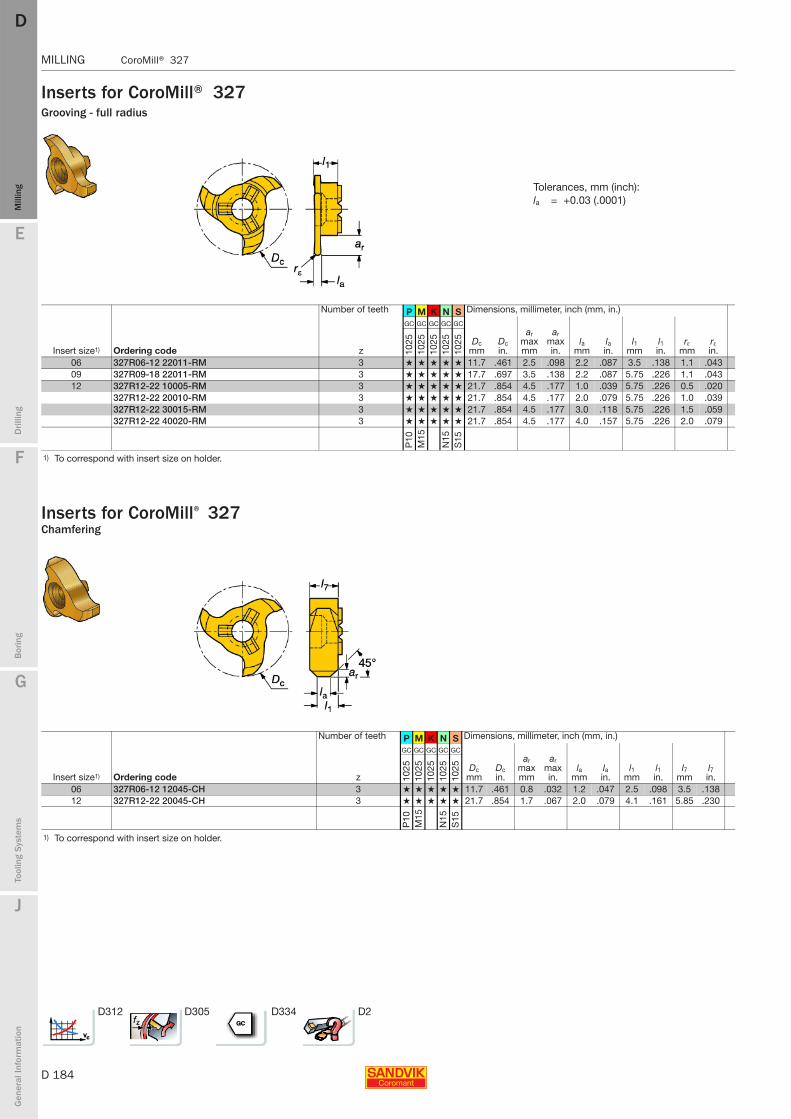
D 184
MILLING CoroMill® 327
E
Mill
ing
Drilli
ng
F
Bor
ing
G
Tool
ing
Syst
ems
J
Gen
eral
Info
rmat
ion
DDM
illin
g
MILLING CoroMill® 327
Inserts for CoroMill® 327Grooving - full radius
Inserts for CoroMill® 327
Number of teeth P M K N S Dimensions, millimeter, inch (mm, in.)
Insert size1) Ordering code z
GC GC GC GC GC
Dcmm
Dcin.
ar maxmm
ar maxin.
lamm
lain.
l1mm
l1in.
rεmm
rεin.10
2510
2510
2510
2510
25
06 327R06-12 22011-RM 3 ★ ★ ★ ★ ★ 11.7 .461 2.5 .098 2.2 .087 3.5 .138 1.1 .04309 327R09-18 22011-RM 3 ★ ★ ★ ★ ★ 17.7 .697 3.5 .138 2.2 .087 5.75 .226 1.1 .04312 327R12-22 10005-RM 3 ★ ★ ★ ★ ★ 21.7 .854 4.5 .177 1.0 .039 5.75 .226 0.5 .020
327R12-22 20010-RM 3 ★ ★ ★ ★ ★ 21.7 .854 4.5 .177 2.0 .079 5.75 .226 1.0 .039327R12-22 30015-RM 3 ★ ★ ★ ★ ★ 21.7 .854 4.5 .177 3.0 .118 5.75 .226 1.5 .059327R12-22 40020-RM 3 ★ ★ ★ ★ ★ 21.7 .854 4.5 .177 4.0 .157 5.75 .226 2.0 .079
P10
M15
N15
S15
1) To correspond with insert size on holder.
Number of teeth P M K N S Dimensions, millimeter, inch (mm, in.)
Insert size1) Ordering code z
GC GC GC GC GC
Dcmm
Dcin.
ar maxmm
ar maxin.
lamm
lain.
l1mm
l1in.
l7mm
l7in.10
2510
2510
2510
2510
25
06 327R06-12 12045-CH 3 ★ ★ ★ ★ ★ 11.7 .461 0.8 .032 1.2 .047 2.5 .098 3.5 .13812 327R12-22 20045-CH 3 ★ ★ ★ ★ ★ 21.7 .854 1.7 .067 2.0 .079 4.1 .161 5.85 .230
P10
M15
N15
S15
1) To correspond with insert size on holder.
D312 D305 D334 D2
Tolerances, mm (inch):la = +0.03 (.0001)
Chamfering
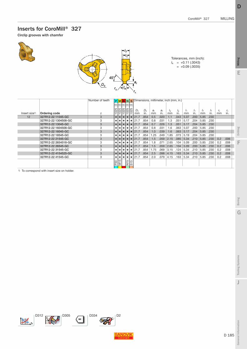
E
D 185
Mill
ing
Drilli
ng
F
Bor
ing
G
Tool
ing
Syst
ems
J
Gen
eral
Info
rmat
ion
DD
Mill
ing
CoroMill® 327 MILLING
MILLING CoroMill® 327
Inserts for CoroMill® 327Circlip grooves with chamfer
Number of teeth P M K N S Dimensions, millimeter, inch (mm, in.)
Insert size1) Ordering code z
GC GC GC GC GC
Dcmm
Dcin.
armm
arin.
lamm
lain.
l1mm
l1in.
l7mm
l7in.
rεmm
rεin.10
2510
2510
2510
2510
25
12 327R12-22 11045-GC 3 ★ ★ ★ ★ ★ 21.7 .854 0.5 .020 1.1 .043 5.07 .200 5.85 .230327R12-22 1304508-GC 3 ★ ★ ★ ★ ★ 21.7 .854 0.8 .031 1.3 .051 5.17 .204 5.85 .230327R12-22 13045-GC 3 ★ ★ ★ ★ ★ 21.7 .854 0.7 .026 1.3 .051 5.17 .204 5.85 .230327R12-22 1604508-GC 3 ★ ★ ★ ★ ★ 21.7 .854 0.8 .031 1.6 .063 5.07 .200 5.85 .230327R12-22 16045-GC 3 ★ ★ ★ ★ ★ 21.7 .854 1.0 .039 1.6 .063 5.17 .204 5.85 .230327R12-22 18545-GC 3 ★ ★ ★ ★ ★ 21.7 .854 1.25 .049 1.85 .073 5.19 .204 5.85 .230327R12-22 21545-GC 3 ★ ★ ★ ★ ★ 21.7 .854 1.5 .059 2.15 .085 5.34 .210 5.85 .230 0.2 .006327R12-22 2654518-GC 3 ★ ★ ★ ★ ★ 21.7 .854 1.8 .071 2.65 .104 5.09 .200 5.85 .230 0.2 .008327R12-22 26545-GC 3 ★ ★ ★ ★ ★ 21.7 .854 1.5 .059 2.65 .104 5.09 .200 5.85 .230 0.2 .006327R12-22 31545-GC 3 ★ ★ ★ ★ ★ 21.7 .854 1.75 .069 3.15 .124 5.34 .210 5.85 .230 0.2 .008327R12-22 4154525-GC 3 ★ ★ ★ ★ ★ 21.7 .854 2.5 .098 4.15 .163 5.34 .210 5.85 .230 0.2 .008327R12-22 41545-GC 3 ★ ★ ★ ★ ★ 21.7 .854 2.0 .079 4.15 .163 5.34 .210 5.85 .230 0.2 .008
P30
M15
N15
S15
1) To correspond with insert size on holder.
D312 D305 D334 D2
Tolerances, mm (inch):la = +0.11 (.0043)
= +0.09 (.0035)
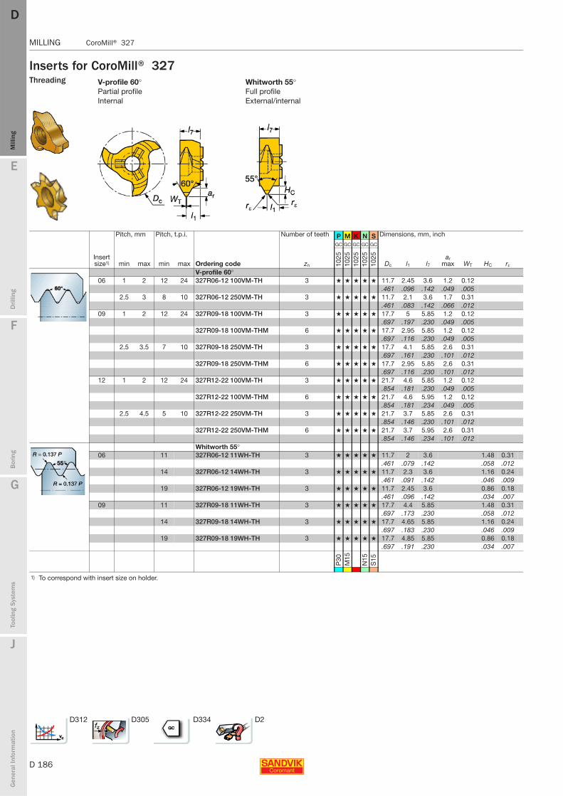
D 186
MILLING CoroMill® 327
E
Mill
ing
Drilli
ng
F
Bor
ing
G
Tool
ing
Syst
ems
J
Gen
eral
Info
rmat
ion
DDM
illin
g
MILLING CoroMill® 327
Inserts for CoroMill® 327Threading V-profile 60° Whitworth 55°
Partial profile Full profileInternal External/internal
Pitch, mm Pitch, t.p.i. Number of teeth P M K N S Dimensions, mm, inch
Insert size1) min max min max Ordering code zn
GC GC GC GC GC
Dc l1 l7ar
max WT HC rε1025
1025
1025
1025
1025
V-profile 60°06 1 2 12 24 327R06-12 100VM-TH 3 ★ ★ ★ ★ ★ 11.7 2.45 3.6 1.2 0.12
.461 .096 .142 .049 .0052.5 3 8 10 327R06-12 250VM-TH 3 ★ ★ ★ ★ ★ 11.7 2.1 3.6 1.7 0.31
.461 .083 .142 .066 .01209 1 2 12 24 327R09-18 100VM-TH 3 ★ ★ ★ ★ ★ 17.7 5 5.85 1.2 0.12
.697 .197 .230 .049 .005327R09-18 100VM-THM 6 ★ ★ ★ ★ ★ 17.7 2.95 5.85 1.2 0.12
.697 .116 .230 .049 .0052.5 3.5 7 10 327R09-18 250VM-TH 3 ★ ★ ★ ★ ★ 17.7 4.1 5.85 2.6 0.31
.697 .161 .230 .101 .012327R09-18 250VM-THM 6 ★ ★ ★ ★ ★ 17.7 2.95 5.85 2.6 0.31
.697 .116 .230 .101 .01212 1 2 12 24 327R12-22 100VM-TH 3 ★ ★ ★ ★ ★ 21.7 4.6 5.85 1.2 0.12
.854 .181 .230 .049 .005327R12-22 100VM-THM 6 ★ ★ ★ ★ ★ 21.7 4.6 5.95 1.2 0.12
.854 .181 .234 .049 .0052.5 4.5 5 10 327R12-22 250VM-TH 3 ★ ★ ★ ★ ★ 21.7 3.7 5.85 2.6 0.31
.854 .146 .230 .101 .012327R12-22 250VM-THM 6 ★ ★ ★ ★ ★ 21.7 3.7 5.95 2.6 0.31
.854 .146 .234 .101 .012Whitworth 55°
06 11 327R06-12 11WH-TH 3 ★ ★ ★ ★ ★ 11.7 2 3.6 1.48 0.31.461 .079 .142 .058 .012
14 327R06-12 14WH-TH 3 ★ ★ ★ ★ ★ 11.7 2.3 3.6 1.16 0.24.461 .091 .142 .046 .009
19 327R06-12 19WH-TH 3 ★ ★ ★ ★ ★ 11.7 2.45 3.6 0.86 0.18.461 .096 .142 .034 .007
09 11 327R09-18 11WH-TH 3 ★ ★ ★ ★ ★ 17.7 4.4 5.85 1.48 0.31.697 .173 .230 .058 .012
14 327R09-18 14WH-TH 3 ★ ★ ★ ★ ★ 17.7 4.65 5.85 1.16 0.24.697 .183 .230 .046 .009
19 327R09-18 19WH-TH 3 ★ ★ ★ ★ ★ 17.7 4.85 5.85 0.86 0.18.697 .191 .230 .034 .007
P30
M15
N15
S15
1) To correspond with insert size on holder.
D312 D305 D334 D2
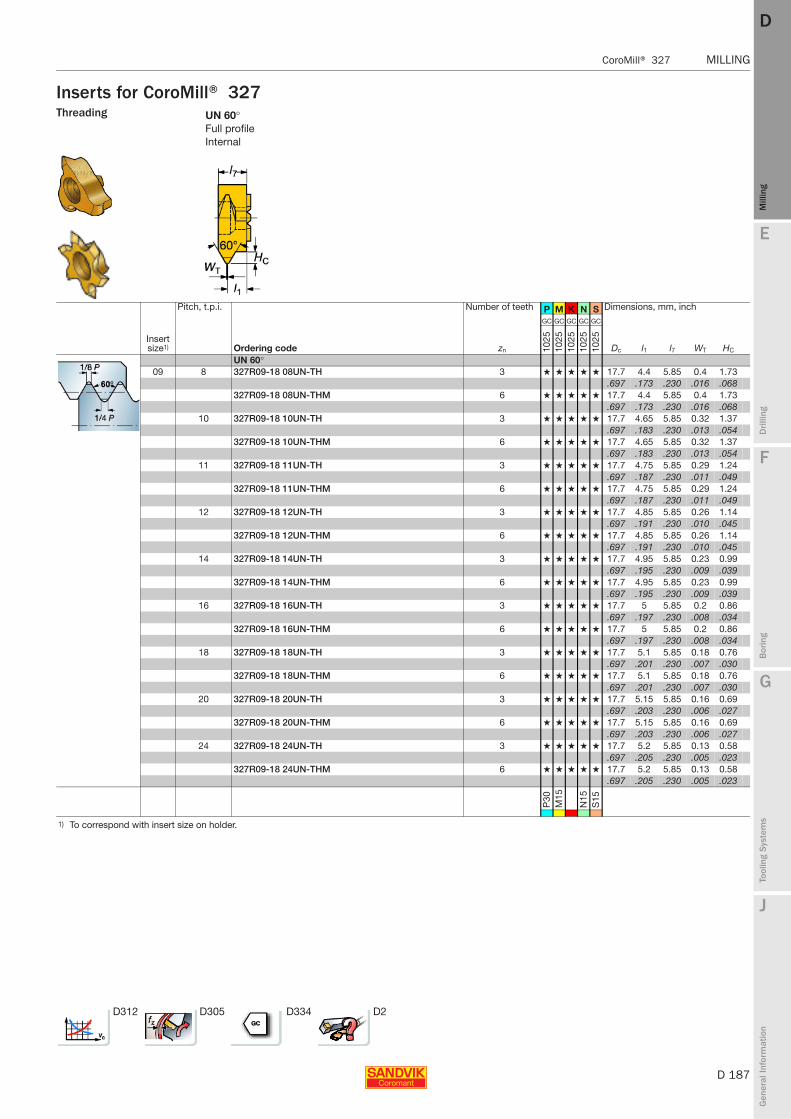
E
D 187
Mill
ing
Drilli
ng
F
Bor
ing
G
Tool
ing
Syst
ems
J
Gen
eral
Info
rmat
ion
DD
Mill
ing
CoroMill® 327 MILLING
MILLING CoroMill® 327
Inserts for CoroMill® 327Threading UN 60°
Full profileInternal
Pitch, t.p.i. Number of teeth P M K N S Dimensions, mm, inch
Insert size1) Ordering code zn
GC GC GC GC GC
Dc l1 l7 WT HC1025
1025
1025
1025
1025
UN 60°09 8 327R09-18 08UN-TH 3 ★ ★ ★ ★ ★ 17.7 4.4 5.85 0.4 1.73
.697 .173 .230 .016 .068327R09-18 08UN-THM 6 ★ ★ ★ ★ ★ 17.7 4.4 5.85 0.4 1.73
.697 .173 .230 .016 .06810 327R09-18 10UN-TH 3 ★ ★ ★ ★ ★ 17.7 4.65 5.85 0.32 1.37
.697 .183 .230 .013 .054327R09-18 10UN-THM 6 ★ ★ ★ ★ ★ 17.7 4.65 5.85 0.32 1.37
.697 .183 .230 .013 .05411 327R09-18 11UN-TH 3 ★ ★ ★ ★ ★ 17.7 4.75 5.85 0.29 1.24
.697 .187 .230 .011 .049327R09-18 11UN-THM 6 ★ ★ ★ ★ ★ 17.7 4.75 5.85 0.29 1.24
.697 .187 .230 .011 .04912 327R09-18 12UN-TH 3 ★ ★ ★ ★ ★ 17.7 4.85 5.85 0.26 1.14
.697 .191 .230 .010 .045327R09-18 12UN-THM 6 ★ ★ ★ ★ ★ 17.7 4.85 5.85 0.26 1.14
.697 .191 .230 .010 .04514 327R09-18 14UN-TH 3 ★ ★ ★ ★ ★ 17.7 4.95 5.85 0.23 0.99
.697 .195 .230 .009 .039327R09-18 14UN-THM 6 ★ ★ ★ ★ ★ 17.7 4.95 5.85 0.23 0.99
.697 .195 .230 .009 .03916 327R09-18 16UN-TH 3 ★ ★ ★ ★ ★ 17.7 5 5.85 0.2 0.86
.697 .197 .230 .008 .034327R09-18 16UN-THM 6 ★ ★ ★ ★ ★ 17.7 5 5.85 0.2 0.86
.697 .197 .230 .008 .03418 327R09-18 18UN-TH 3 ★ ★ ★ ★ ★ 17.7 5.1 5.85 0.18 0.76
.697 .201 .230 .007 .030327R09-18 18UN-THM 6 ★ ★ ★ ★ ★ 17.7 5.1 5.85 0.18 0.76
.697 .201 .230 .007 .03020 327R09-18 20UN-TH 3 ★ ★ ★ ★ ★ 17.7 5.15 5.85 0.16 0.69
.697 .203 .230 .006 .027327R09-18 20UN-THM 6 ★ ★ ★ ★ ★ 17.7 5.15 5.85 0.16 0.69
.697 .203 .230 .006 .02724 327R09-18 24UN-TH 3 ★ ★ ★ ★ ★ 17.7 5.2 5.85 0.13 0.58
.697 .205 .230 .005 .023327R09-18 24UN-THM 6 ★ ★ ★ ★ ★ 17.7 5.2 5.85 0.13 0.58
.697 .205 .230 .005 .023
P30
M15
N15
S15
1) To correspond with insert size on holder.
D312 D305 D334 D2
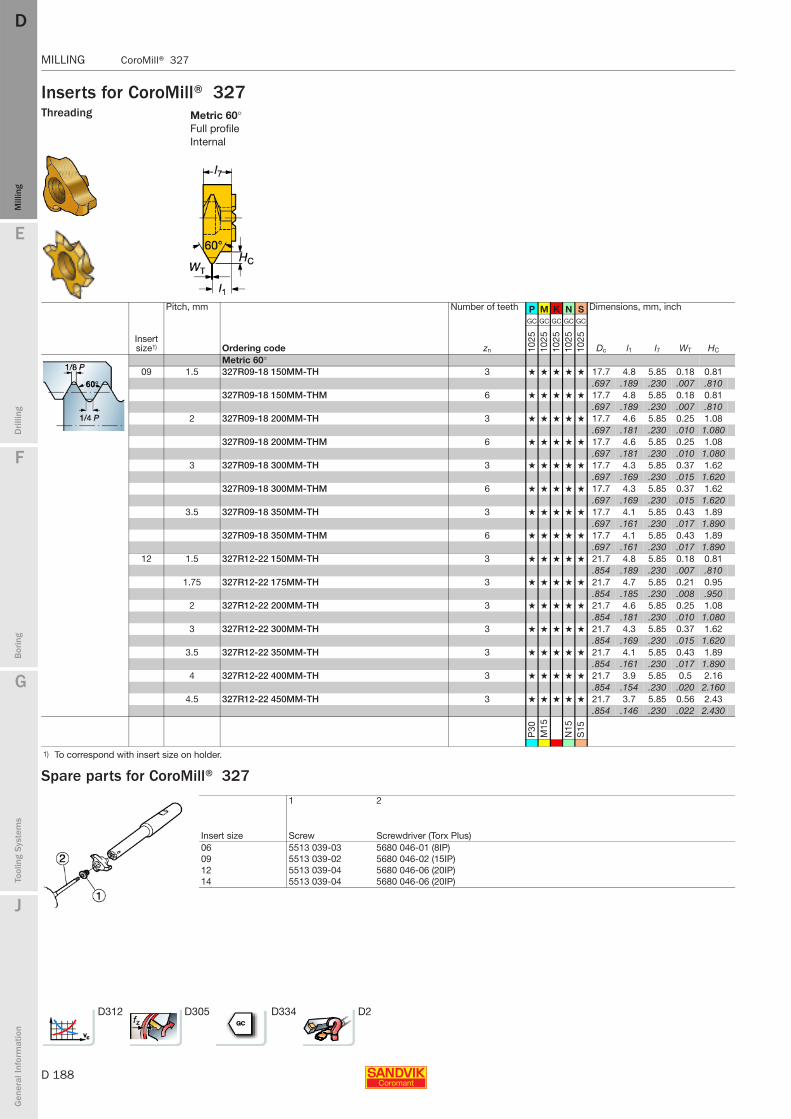
D 188
MILLING CoroMill® 327
E
Mill
ing
Drilli
ng
F
Bor
ing
G
Tool
ing
Syst
ems
J
Gen
eral
Info
rmat
ion
DDM
illin
g
MILLING CoroMill® 327
Inserts for CoroMill® 327Threading
Spare parts for CoroMill® 327
Metric 60°Full profileInternal
Pitch, mm Number of teeth P M K N S Dimensions, mm, inch
Insert size1) Ordering code zn
GC GC GC GC GC
Dc l1 l7 WT HC1025
1025
1025
1025
1025
Metric 60°09 1.5 327R09-18 150MM-TH 3 ★ ★ ★ ★ ★ 17.7 4.8 5.85 0.18 0.81
.697 .189 .230 .007 .810327R09-18 150MM-THM 6 ★ ★ ★ ★ ★ 17.7 4.8 5.85 0.18 0.81
.697 .189 .230 .007 .8102 327R09-18 200MM-TH 3 ★ ★ ★ ★ ★ 17.7 4.6 5.85 0.25 1.08
.697 .181 .230 .010 1.080327R09-18 200MM-THM 6 ★ ★ ★ ★ ★ 17.7 4.6 5.85 0.25 1.08
.697 .181 .230 .010 1.0803 327R09-18 300MM-TH 3 ★ ★ ★ ★ ★ 17.7 4.3 5.85 0.37 1.62
.697 .169 .230 .015 1.620327R09-18 300MM-THM 6 ★ ★ ★ ★ ★ 17.7 4.3 5.85 0.37 1.62
.697 .169 .230 .015 1.6203.5 327R09-18 350MM-TH 3 ★ ★ ★ ★ ★ 17.7 4.1 5.85 0.43 1.89
.697 .161 .230 .017 1.890327R09-18 350MM-THM 6 ★ ★ ★ ★ ★ 17.7 4.1 5.85 0.43 1.89
.697 .161 .230 .017 1.89012 1.5 327R12-22 150MM-TH 3 ★ ★ ★ ★ ★ 21.7 4.8 5.85 0.18 0.81
.854 .189 .230 .007 .8101.75 327R12-22 175MM-TH 3 ★ ★ ★ ★ ★ 21.7 4.7 5.85 0.21 0.95
.854 .185 .230 .008 .9502 327R12-22 200MM-TH 3 ★ ★ ★ ★ ★ 21.7 4.6 5.85 0.25 1.08
.854 .181 .230 .010 1.0803 327R12-22 300MM-TH 3 ★ ★ ★ ★ ★ 21.7 4.3 5.85 0.37 1.62
.854 .169 .230 .015 1.6203.5 327R12-22 350MM-TH 3 ★ ★ ★ ★ ★ 21.7 4.1 5.85 0.43 1.89
.854 .161 .230 .017 1.8904 327R12-22 400MM-TH 3 ★ ★ ★ ★ ★ 21.7 3.9 5.85 0.5 2.16
.854 .154 .230 .020 2.1604.5 327R12-22 450MM-TH 3 ★ ★ ★ ★ ★ 21.7 3.7 5.85 0.56 2.43
.854 .146 .230 .022 2.430
P30
M15
N15
S15
1) To correspond with insert size on holder.
Insert size
1 2
Screw Screwdriver (Torx Plus)06 5513 039-03 5680 046-01 (8IP)09 5513 039-02 5680 046-02 (15IP)12 5513 039-04 5680 046-06 (20IP)14 5513 039-04 5680 046-06 (20IP)
D312 D305 D334 D2
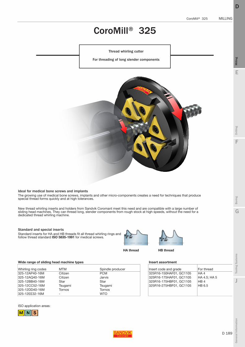
E
D 189
Mill
ing
Drilli
ng
F
Bor
ing
G
Tool
ing
Syst
ems
J
Gen
eral
Info
rmat
ion
DD
Mill
ing
CoroMill® 325 MILLING
MILLING CoroMill® 325
CoroMill® 325
Thread whirling cutter
For threading of long slender components
ISO application areas:
Ideal for medical bone screws and implantsThe growing use of medical bone screws, implants and other micro-components creates a need for techniques that produce special thread forms quickly and at high tolerances.
New thread whirling inserts and holders from Sandvik Coromant meet this need and are compatible with a large number of sliding head machines. They can thread long, slender components from rough stock at high speeds, without the need for a dedicated thread whirling machine.
Standard and special insertsStandard inserts for HA and HB threads fit all thread whirling rings and follow thread standard ISO 5835-1991 for medical screws.
HA thread HB thread
Wide range of sliding head machine types Insert assortment
Whirling ring codes MTM Spindle producer Insert code and grade For thread325-12AP40-16M Citizen PCM 325R16-150HAF01, GC1105 HA 4325-12AQ40-16M Citizen Jarvis 325R16-175HAF01, GC1105 HA 4.5; HA 5325-12BB40-16M Star Star 325R16-175HBF01, GC1105 HB 4325-12CC52-16M Tsugami Tsugami 325R16-275HBF01, GC1105 HB 6.5325-12DD40-16M Tornos Tornos325-12EE32-16M - WTO
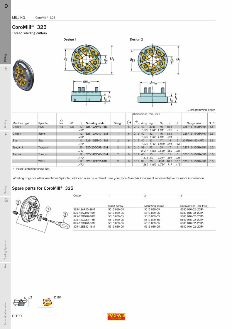
D 190
MILLING CoroMill® 325
E
Mill
ing
Drilli
ng
F
Bor
ing
G
Tool
ing
Syst
ems
J
Gen
eral
Info
rmat
ion
DDM
illin
g
MILLING CoroMill® 325
CoroMill® 325Thread whirling cutters
Spare parts for CoroMill® 325
Design 1 Design 2
l1 = programming length
Dimensions, mm, inch
Machine type Spindle D iC dc Ordering code Design e U dmm d21 D1 l1 l3 Gauge insert Nm1)
Citizen PCM 16 3/8 12 325-12AP40-16M 1 6 0.12 40 32.5 46 15.5 - 325R16-150HAF01 6.5.472 1.575 1.280 1.811 .610 -
Citizen Jarvis 12 325-12AQ40-16M 1 6 0.12 40 32 46 13.5 - 325R16-150HAF01 6.5.472 1.575 1.260 1.811 .531 -
Star Star 12 325-12BB40-16M 2 6 0.12 40 32 47 15 9 325R16-150HAF01 6.5.472 1.575 1.260 1.850 .591 .354
Tsugami Tsugami 20 325-20CC52-16M 2 6 0.15 52 42 65 17 6 325R16-150HAF01 6.5.787 2.047 1.654 2.559 .669 .236
Tornos Tornos 12 325-12DD40-16M 2 6 0.12 40 15 57 15 6 325R16-150HAF01 6.5.472 1.575 .591 2.244 .591 .236
WTO 12 325-12EE32-16M 2 6 0.12 32 28 43.8 18.2 10.5 325R16-150HAF01 6.5.472 1.260 1.102 1.724 .717 .413
1) Insert tightening torque Nm.
Whirling rings for other machines/spindle units can also be ordered. See your local Sandvik Coromant representative for more information.
Cutter 1 2 3
Insert screw Mounting screw Screwdriver (Torx Plus)325-12AP40-16M 5513 039-05 5513 039-05 5680 046-02 (20IP)325-12AQ40-16M 5513 039-05 5513 039-05 5680 046-02 (20IP)325-12BB40-16M 5513 039-05 5513 039-05 5680 046-02 (20IP)325-12CC52-16M 5513 039-05 5513 020-55 5680 046-02 (20IP)325-12DD40-16M 5513 039-05 5513 039-05 5680 046-02 (20IP)325-12EE32-16M 5513 039-05 5513 039-05 5680 046-02 (20IP)
J2 D191
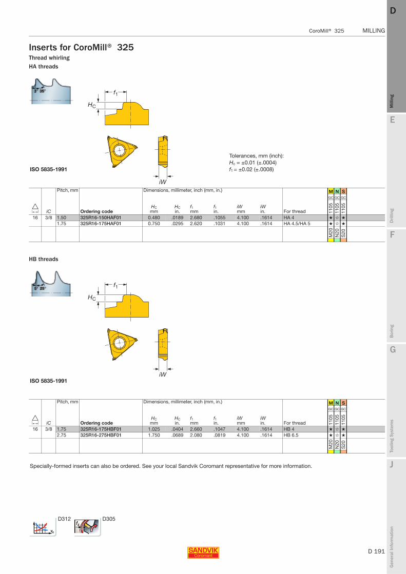
E
D 191
Mill
ing
Drilli
ng
F
Bor
ing
G
Tool
ing
Syst
ems
J
Gen
eral
Info
rmat
ion
DD
Mill
ing
CoroMill® 325 MILLING
MILLING CoroMill® 325
Inserts for CoroMill® 325Thread whirlingHA threads
HB threads
Tolerances, mm (inch):Hc = ±0.01 (±.0004)
ISO 5835-1991 f1 = ±0.02 (±.0008)
Pitch, mm Dimensions, millimeter, inch (mm, in.) M N S
D iC Ordering codeHCmm
HCin.
f1mm
f1in.
iWmm
iWin. For thread
GC GC GC
1105
1105
1105
16 3/8 1.50 325R16-150HAF01 0.480 .0189 2.680 .1055 4.100 .1614 HA 4 ★ ✩ ★
1.75 325R16-175HAF01 0.750 .0295 2.620 .1031 4.100 .1614 HA 4.5/HA 5 ★ ✩ ★
M20
N20
S20
ISO 5835-1991
Pitch, mm Dimensions, millimeter, inch (mm, in.) M N S
D iC Ordering codeHCmm
HCin.
f1mm
f1in.
iWmm
iWin. For thread
GC GC GC
1105
1105
1105
16 3/8 1.75 325R16-175HBF01 1.025 .0404 2.660 .1047 4.100 .1614 HB 4 ★ ✩ ★
2.75 325R16-275HBF01 1.750 .0689 2.080 .0819 4.100 .1614 HB 6.5 ★ ✩ ★
M20
N20
S20
Specially-formed inserts can also be ordered. See your local Sandvik Coromant representative for more information.
D312 D305

D 192
MILLING CoroMill® 325
E
Mill
ing
Drilli
ng
F
Bor
ing
G
Tool
ing
Syst
ems
J
Gen
eral
Info
rmat
ion
DDM
illin
g
MILLING CoroMill® 325
Inserts for CoroMill® 325Thread whirlingBlanks
Tolerances, mm (inch):s = ±0.02 (±.0008)
Dimensions, millimeter, inch (mm, in.) P M K N S
D iC Ordering codes
mms
in.
- - - - -
H10
FH
10F
H10
FH
10F
H10
F
16 3/8 325R16-0400-BG 4.0 .157 ★ ★ ★ ★ ★
325R16-0500-BG 5.5 .217 ★ ★ ★ ★ ★
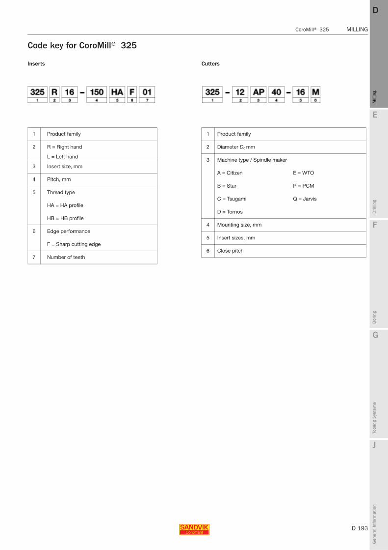
E
D 193
Mill
ing
Drilli
ng
F
Bor
ing
G
Tool
ing
Syst
ems
J
Gen
eral
Info
rmat
ion
DD
Mill
ing
CoroMill® 325 MILLING
MILLING CoroMill® 325
Code key for CoroMill® 325
1 Product family
2 R = Right hand
L = Left hand
3 Insert size, mm
4 Pitch, mm
5 Thread type
HA = HA profile
HB = HB profile
6 Edge performance
F = Sharp cutting edge
7 Number of teeth
1 Product family
2 Diameter Dc mm
3 Machine type / Spindle maker
A = Citizen E = WTO
B = Star P = PCM
C = Tsugami Q = Jarvis
D = Tornos
4 Mounting size, mm
5 Insert sizes, mm
6 Close pitch
Inserts Cutters
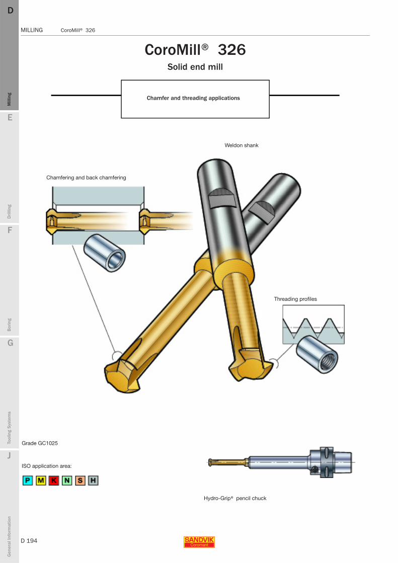
D 194
MILLING CoroMill® 326
E
Mill
ing
Drilli
ng
F
Bor
ing
G
Tool
ing
Syst
ems
J
Gen
eral
Info
rmat
ion
DDM
illin
g
MILLING CoroMill® 326
CoroMill® 326Solid end mill
Chamfer and threading applications
Chamfering and back chamfering
Grade GC1025
ISO application area:
Weldon shank
Threading profiles
Hydro-Grip® pencil chuck
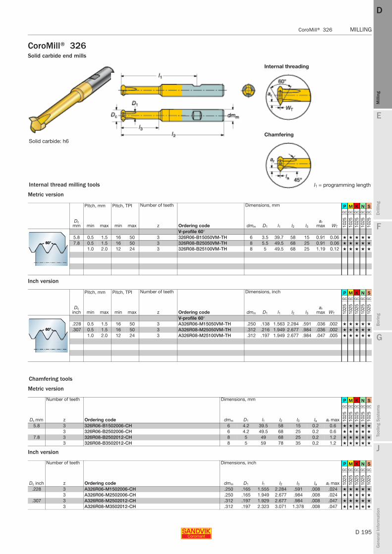
E
D 195
Mill
ing
Drilli
ng
F
Bor
ing
G
Tool
ing
Syst
ems
J
Gen
eral
Info
rmat
ion
DD
Mill
ing
CoroMill® 326 MILLING
MILLING CoroMill® 326
CoroMill® 326Solid carbide end mills
Metric version
Inch version
Metric version
Inch version
Internal threading
ChamferingSolid carbide: h6
Internal thread milling tools l1 = programming length
Pitch, mm Pitch, TPI Number of teeth Dimensions, mm P M K N S
Dc mm min max min max z Ordering code dmm D1 l1 l2 l3
ar max WT
GC GC GC GC GC
1025
1025
1025
1025
1025
V-profile 60°5.8 0.5 1.5 16 50 3 326R06-B15050VM-TH 6 3.5 39.7 58 15 0.91 0.06 ★ ★ ★ ★ ★
7.8 0.5 1.5 16 50 3 326R08-B25050VM-TH 8 5.5 49.5 68 25 0.91 0.06 ★ ★ ★ ★ ★
1.0 2.0 12 24 3 326R08-B25100VM-TH 8 5 49.5 68 25 1.19 0.12 ★ ★ ★ ★ ★
Pitch, mm Pitch, TPI Number of teeth Dimensions, inch P M K N S
Dc inch min max min max z Ordering code dmm D1 l1 l2 l3
ar max WT
GC GC GC GC GC
1025
1025
1025
1025
1025
V-profile 60°.228 0.5 1.5 16 50 3 A326R06-M15050VM-TH .250 .138 1.563 2.284 .591 .036 .002 ★ ★ ★ ★ ★
.307 0.5 1.5 16 50 3 A326R08-M25050VM-TH .312 .216 1.949 2.677 .984 .036 .002 ★ ★ ★ ★ ★
1.0 2.0 12 24 3 A326R08-M25100VM-TH .312 .197 1.949 2.677 .984 .047 .005 ★ ★ ★ ★ ★
Chamfering tools
Number of teeth Dimensions, mm P M K N S
Dc mm z Ordering code dmm D1 l1 l2 l3 la ar max
GC GC GC GC GC
1025
1025
1025
1025
1025
5.8 3 326R06-B1502006-CH 6 4.2 39.5 58 15 0.2 0.6 ★ ★ ★ ★ ★
3 326R06-B2502006-CH 6 4.2 49.5 68 25 0.2 0.6 ★ ★ ★ ★ ★
7.8 3 326R08-B2502012-CH 8 5 49 68 25 0.2 1.2 ★ ★ ★ ★ ★
3 326R08-B3502012-CH 8 5 59 78 35 0.2 1.2 ★ ★ ★ ★ ★
Number of teeth Dimensions, inch P M K N S
Dc inch z Ordering code dmm D1 l1 l2 l3 la ar max
GC GC GC GC GC
1025
1025
1025
1025
1025
.228 3 A326R06-M1502006-CH .250 .165 1.555 2.284 .591 .008 .024 ★ ★ ★ ★ ★
3 A326R06-M2502006-CH .250 .165 1.949 2.677 .984 .008 .024 ★ ★ ★ ★ ★
.307 3 A326R08-M2502012-CH .312 .197 1.929 2.677 .984 .008 .047 ★ ★ ★ ★ ★
3 A326R08-M3502012-CH .312 .197 2.323 3.071 1.378 .008 .047 ★ ★ ★ ★ ★

D 196
MILLING CoroMill® 170
E
Mill
ing
Drilli
ng
F
Bor
ing
G
Tool
ing
Syst
ems
J
Gen
eral
Info
rmat
ion
DDM
illin
g
MILLING CoroMill® 170
CoroMill® 170
Rough gear milling with precision
Tool profile according to DIN3972-4
Insert geometries
High productivity
- Secure and stable insert seats- High feed rates- High cutting speeds
Minimal and even finishing allowance
ISO application areas:
High precision cutter body and inserts
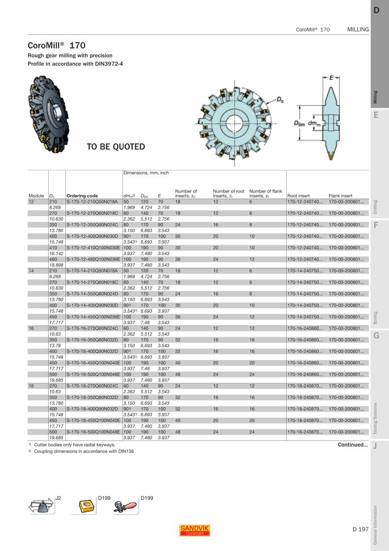
E
D 197
Mill
ing
Drilli
ng
F
Bor
ing
G
Tool
ing
Syst
ems
J
Gen
eral
Info
rmat
ion
DD
Mill
ing
CoroMill® 170 MILLING
MILLING CoroMill® 170
CoroMill® 170Rough gear milling with precisionProfile in accordance with DIN3972-4
Dimensions, mm, inch
Module Dc Ordering code dmm2) D5m ENumber of inserts, zn
Number of root inserts, zr
Number of flank inserts, zf Root insert Flank insert
12 210 S-170-12-210Q50N018A 50 120 70 18 12 6 170-12-240740... 170-00-200801...8.268 1.969 4.724 2.756270 S-170-12-270Q60N018C 60 140 70 18 12 6 170-12-240740... 170-00-200801...10.630 2.362 5.512 2.756350 S-170-12-350Q80N024C 80 170 90 24 16 8 170-12-240740... 170-00-200801...13.780 3.150 6.693 3.543400 S-170-12-400Q90N030D 901) 170 100 30 20 10 170-12-240740... 170-00-200801...15.748 3.5431) 6.693 3.937410 S-170-12-410Q100N030E 100 190 90 30 20 10 170-12-240740... 170-00-200801...16.142 3.937 7.480 3.543480 S-170-12-480Q100N036E 100 190 90 36 24 12 170-12-240740... 170-00-200801...18.898 3.937 7.480 3.543
14 210 S-170-14-210Q50N018A 50 120 70 18 12 6 170-14-240750... 170-00-200801...8.268 1.969 4.724 2.756270 S-170-14-270Q60N018C 60 140 70 18 12 6 170-14-240750... 170-00-200801...10.630 2.362 5.512 2.756350 S-170-14-350Q80N024D 80 170 90 24 16 8 170-14-240750... 170-00-200801...13.780 3.150 6.693 3.543400 S-170-14-400Q90N030D 901) 170 100 30 20 10 170-14-240750... 170-00-200801...15.748 3.5431) 6.693 3.937450 S-170-14-450Q100N036E 100 190 90 36 24 12 170-14-240750... 170-00-200801...17.717 3.937 7.48 3.543
16 270 S-170-16-270Q60N024C 60 140 90 24 12 12 170-16-240860... 170-00-200801...10.63 2.362 5.512 3.543350 S-170-16-350Q80N032D 80 170 90 32 16 16 170-16-240860... 170-00-200801...13.78 3.150 6.693 3.543400 S-170-16-400Q90N032D 901) 170 100 32 16 16 170-16-240860... 170-00-200801...15.748 3.5431) 6.693 3.937450 S-170-16-450Q100N040E 100 190 100 40 20 20 170-16-240860... 170-00-200801...17.717 3.937 7.48 3.937500 S-170-16-500Q100N048E 100 190 100 48 24 24 170-16-240860... 170-00-200801...19.685 3.937 7.480 3.937
18 270 S-170-18-270Q60N024C 60 140 90 24 12 12 170-18-240870... 170-00-200801...10.63 2.362 5.512 3.543350 S-170-18-350Q80N032D 80 170 90 32 16 16 170-18-240870... 170-00-200801...13.780 3.150 6.693 3.543400 S-170-18-400Q90N032D 901) 170 100 32 16 16 170-18-240870... 170-00-200801...15.748 3.5431) 6.693 3.937450 S-170-18-450Q100N040E 100 190 100 40 20 20 170-18-240870... 170-00-200801...17.717 3.937 7.480 3.937500 S-170-18-500Q100N048E 100 190 100 48 24 24 170-18-240870... 170-00-200801...19.685 3.937 7.480 3.937
1) Cutter bodies only have radial keyways. Continued...2) Coupling dimensions in accordance with DIN138
TO BE QUOTED
J2 D199 D199
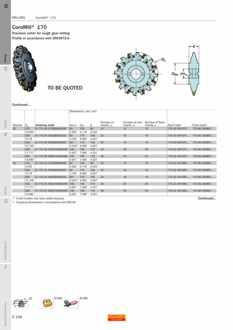
D 198
MILLING CoroMill® 170
E
Mill
ing
Drilli
ng
F
Bor
ing
G
Tool
ing
Syst
ems
J
Gen
eral
Info
rmat
ion
DDM
illin
g
MILLING CoroMill® 170
CoroMill® 170Precision cutter for rough gear millingProfile in accordance with DIN3972-4
Continued...
Dimensions, mm, inch
Module Dc Ordering code dmm2) D5m ENumber of inserts, zn
Number of root inserts, zr
Number of flank inserts, zf Root insert Flank insert
20 270 S-170-20-270Q60N024B 60 130 90 24 12 12 170-20-281075... 170-00-200801...10.630 2.362 5.118 3.543350 S-170-20-350Q80N032D 80 170 100 32 16 16 170-20-281075... 170-00-200801...13.78 3.150 6.693 3.937400 S-170-20-400Q90N032D 901) 170 100 32 16 16 170-20-281075... 170-00-200801...15.748 3.5431) 6.693 3.937450 S-170-20-450Q100N040E 100 190 110 40 20 20 170-20-281075... 170-00-200801...17.717 3.937 7.480 4.331500 S-170-20-500Q100N048E 100 190 110 48 24 24 170-20-281075... 170-00-200801...19.685 3.937 7.480 4.331
22 270 S-170-22-270Q60N024B 60 130 90 24 12 12 170-22-281085... 170-00-200801...10.63 2.362 5.118 3.543350 S-170-22-350Q80N032D 80 170 100 32 16 16 170-22-281085... 170-00-200801...13.78 3.150 6.693 3.937400 S-170-22-400Q90N032D 901) 170 100 32 16 16 170-22-281085... 170-00-200801...15.748 3.5431) 6.693 3.937450 S-170-22-450Q100N040E 100 190 110 40 20 20 170-22-281085... 170-00-200801...17.717 3.937 7.480 4.331500 S-170-22-500Q100N048E 100 190 110 48 24 24 170-22-281085... 170-00-200801...19.685 3.937 7.480 4.331
1) Cutter bodies only have radial keyways. Continued...2) Coupling dimensions in accordance with DIN138
TO BE QUOTED
J2 D199 D199
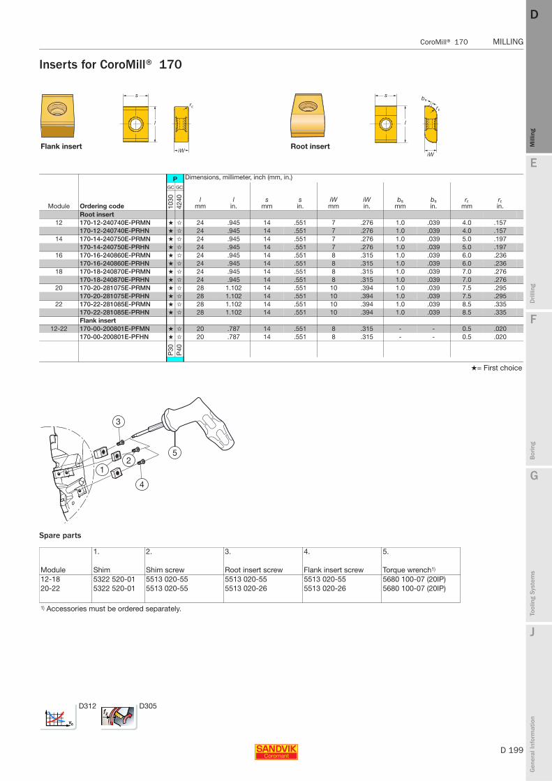
E
D 199
Mill
ing
Drilli
ng
F
Bor
ing
G
Tool
ing
Syst
ems
J
Gen
eral
Info
rmat
ion
DD
Mill
ing
CoroMill® 170 MILLING
MILLING CoroMill® 170
Inserts for CoroMill® 170
Spare parts
Flank insert Root insert
P Dimensions, millimeter, inch (mm, in.)
Module Ordering code
GC GC
lmm
lin.
smm
sin.
iWmm
iWin.
bsmm
bsin.
rεmm
rεin.10
3042
40
Root insert12 170-12-240740E-PRMN ★ ✩ 24 .945 14 .551 7 .276 1.0 .039 4.0 .157
170-12-240740E-PRHN ★ ✩ 24 .945 14 .551 7 .276 1.0 .039 4.0 .15714 170-14-240750E-PRMN ★ ✩ 24 .945 14 .551 7 .276 1.0 .039 5.0 .197
170-14-240750E-PRHN ★ ✩ 24 .945 14 .551 7 .276 1.0 .039 5.0 .19716 170-16-240860E-PRMN ★ ✩ 24 .945 14 .551 8 .315 1.0 .039 6.0 .236
170-16-240860E-PRHN ★ ✩ 24 .945 14 .551 8 .315 1.0 .039 6.0 .23618 170-18-240870E-PRMN ★ ✩ 24 .945 14 .551 8 .315 1.0 .039 7.0 .276
170-18-240870E-PRHN ★ ✩ 24 .945 14 .551 8 .315 1.0 .039 7.0 .27620 170-20-281075E-PRMN ★ ✩ 28 1.102 14 .551 10 .394 1.0 .039 7.5 .295
170-20-281075E-PRHN ★ ✩ 28 1.102 14 .551 10 .394 1.0 .039 7.5 .29522 170-22-281085E-PRMN ★ ✩ 28 1.102 14 .551 10 .394 1.0 .039 8.5 .335
170-22-281085E-PRHN ★ ✩ 28 1.102 14 .551 10 .394 1.0 .039 8.5 .335Flank insert
12-22 170-00-200801E-PFMN ★ ✩ 20 .787 14 .551 8 .315 - - 0.5 .020170-00-200801E-PFHN ★ ✩ 20 .787 14 .551 8 .315 - - 0.5 .020
P30
P40
★= First choice
1. 2. 3. 4. 5.
Module Shim Shim screw Root insert screw Flank insert screw Torque wrench1)
12-18 5322 520-01 5513 020-55 5513 020-55 5513 020-55 5680 100-07 (20IP)20-22 5322 520-01 5513 020-55 5513 020-26 5513 020-26 5680 100-07 (20IP)
1) Accessories must be ordered separately.
D312 D305

D 200
MILLING CoroMill® 170
E
Mill
ing
Drilli
ng
F
Bor
ing
G
Tool
ing
Syst
ems
J
Gen
eral
Info
rmat
ion
DDM
illin
g
MILLING CoroMill® 170
Feed recommendationsStarting values
Cutting speed recommendations
Geometry Geometry ..H. ..M.
ModuleDiameter
zc1)ae1mm
ae1inch
ae2mm
ae2inch
fz1mm
fz1inch
fz2mm
fz2inch
fz1mm
fz1inch
fz2mm
fz2inchmm inch
12 210 8.268 6/3 27 1.063 - - 0.31-0.43 .012-.017 - - 0.24-0.36 .009-.014 - -270 10.630 6/3 27 1.063 - - 0.36-0.48 .015-.019 - - 0.27-0.39 .011-.015 - -350 13.780 8/4 27 1.063 - - 0.41-0.53 .016-.021 - - 0.31-0.43 .012-.017 - -400 15.748 10/5 27 1.063 - - 0.44-0.56 .017-.022 - - 0.34-0.46 .013-.018 - -410 16.142 10/5 27 1.063 - - 0.44-0.56 .017-.022 - - 0.34-0.46 .013-.018 - -480 18.898 12/6 27 1.063 - - 0.60-0.66 .024-.026 - - 0.37-0.49 .015-.019 - -
14 210 8.268 6/3 31.5 1.240 - - 0.31-0.43 .012-.017 - - 0.22-0.34 .009-.013 - -270 10.630 6/3 31.5 1.240 - - 0.33-0.45 .013-.018 - - 0.25-0.37 .010-.015 - -350 13.780 8/4 31.5 1.240 - - 0.38-0.5 .015-.020 - - 0.29-0.41 .011-.016 - -400 15.748 10/5 31.5 1.240 - - 0.40-0.52 .016-.020 - - 0.31-0.43 .012-.017 - -450 17.717 12/6 31.5 1.240 - - 0.43-0.51 .017-.020 - - 0.33-0.45 .013-.018 - -
16 270 10.630 6/3 36 1.417 - - 0.31-0.43 .012-.017 - - 0.23-0.35 .009-.014 - -350 13.780 8/4 36 1.417 - - 0.35-0.47 .014-.019 - - 0.27-0.39 .011-.015 - -400 15.748 8/4 36 1.417 - - 0.38-0.5 .015-.020 - - 0.29-0.41 .011-.016 - -450 17.717 10/5 36 1.417 - - 0.40-0.52 .016-.020 - - 0.31-0.43 .012-.017 - -500 19.685 12/6 36 1.417 - - 0.42-0.54 .017-.021 - - 0.33-0.45 .013-.018 - -
18 270 10.630 6/3 40.5 1.594 - - 0.29-0.41 .011-.016 - - 0.22-0.34 .009-.013 - -350 13.780 8/4 40.5 1.594 - - 0.33-0.45 .013-.018 - - 0.25-0.37 .010-.015 - -400 15.748 8/4 40.5 1.594 - - 0.35-0.47 .014-.019 - - 0.27-0.39 .011-.015 - -450 17.717 10/5 40.5 1.594 - - 0.38-0.5 .015-.020 - - 0.29-0.41 .011-.016 - -500 19.685 12/6 40.5 1.594 - - 0.40-0.52 .016-.020 - - 0.31-0.43 .012-.017 - -
20 270 10.630 6/3 45 1.772 - - 0.28-0,40 .011-.016 - - 0.21-0.33 .008-.013 - -350 13.780 8/4 45 1.772 - - 0.31-0.43 .012-.017 - - 0.24-0.36 .009-.014 - -400 15.748 8/4 45 1.772 - - 0.34-0.46 .013-.018 - - 0.26-0.38 .010-.015 - -450 17.717 10/5 45 1.772 - - 0.36-0.48 .015-.019 - - 0.27-0.39 .011-.015 - -500 19.685 12/6 45 1.772 - - 0.38-0.5 .015-.020 - - 0.29-0.41 .011-.016 - -
22 270 10.630 6/3 40 1.575 10 .394 0.29-0.41 .011-.016 0.60-0.74 .024-.029 0.22-0.34 .009-.013 0.47-0.59 .019-.023350 13.780 8/4 40 1.575 10 .394 0.33-0.45 .013-.018 0.69-0.81 .027-.032 0.25-0.37 .010-.015 0.54-0.66 .021-.024400 15.748 8/4 40 1.575 10 .394 0.36-0.48 .015-.019 0.74-0.86 .029-.034 0.27-0.39 .011-.015 0.58-0.70 .023-.028450 17.717 10/5 40 1.575 10 .394 0.38-0.5 .015-.020 0.79-0.91 .031-.036 0.29-0.41 .011-.016 0.62-0.74 .024-.029500 19.685 12/6 40 1.575 10 .394 0.40-0.52 .016-.020 0.83-0.95 .033-.037 0.31-0.43 .012-.017 0.65-0.77 .026-.030
1) Effective number of inserts, root inserts/flank inserts
Starting values
P vc m/min (ft/min)GC1030 120-160 (395-525)GC4240 100-140 (330-460)
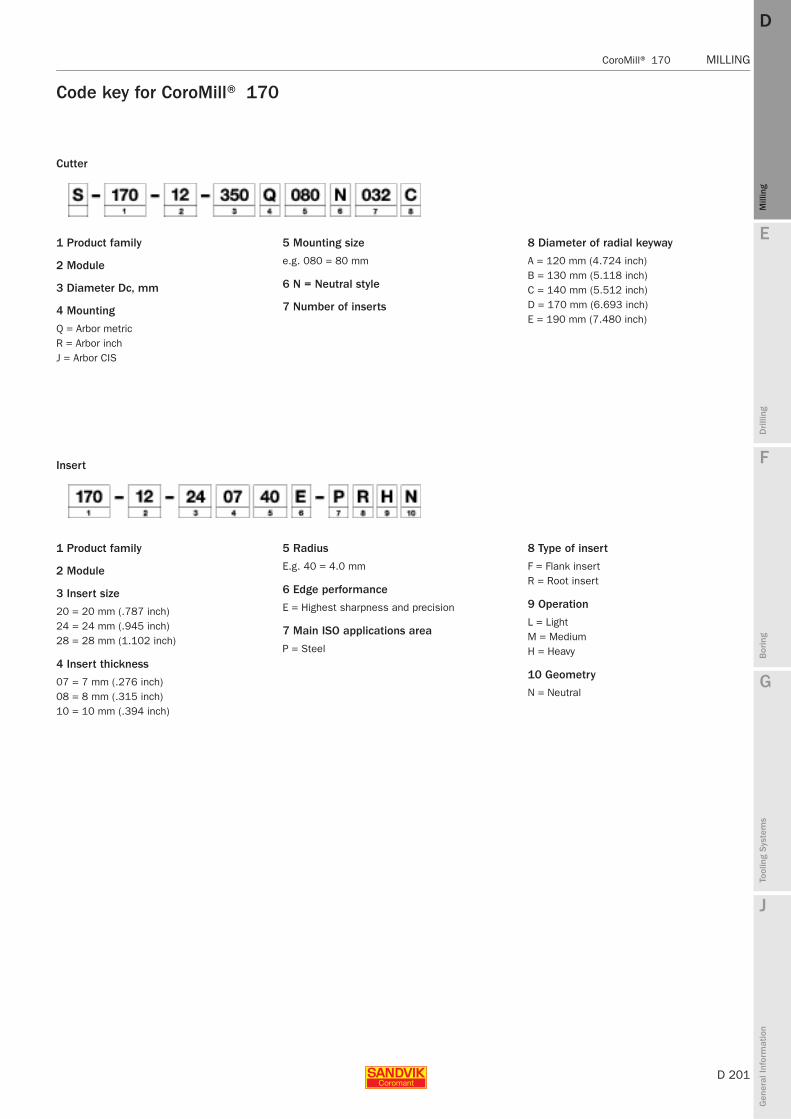
E
D 201
Mill
ing
Drilli
ng
F
Bor
ing
G
Tool
ing
Syst
ems
J
Gen
eral
Info
rmat
ion
DD
Mill
ing
CoroMill® 170 MILLING
MILLING CoroMill® 170
Code key for CoroMill® 170
Cutter
1 Product family
2 Module
3 Diameter Dc, mm
4 Mounting
Q = Arbor metricR = Arbor inchJ = Arbor CIS
5 Mounting size
e.g. 080 = 80 mm
6 N = Neutral style
7 Number of inserts
8 Diameter of radial keyway
A = 120 mm (4.724 inch)B = 130 mm (5.118 inch)C = 140 mm (5.512 inch)D = 170 mm (6.693 inch)E = 190 mm (7.480 inch)
Insert
1 Product family
2 Module
3 Insert size
20 = 20 mm (.787 inch)24 = 24 mm (.945 inch)28 = 28 mm (1.102 inch)
4 Insert thickness
07 = 7 mm (.276 inch)08 = 8 mm (.315 inch)10 = 10 mm (.394 inch)
5 Radius
E.g. 40 = 4.0 mm
6 Edge performance
E = Highest sharpness and precision
7 Main ISO applications area
P = Steel
8 Type of insert
F = Flank insertR = Root insert
9 Operation
L = LightM = MediumH = Heavy
10 Geometry
N = Neutral
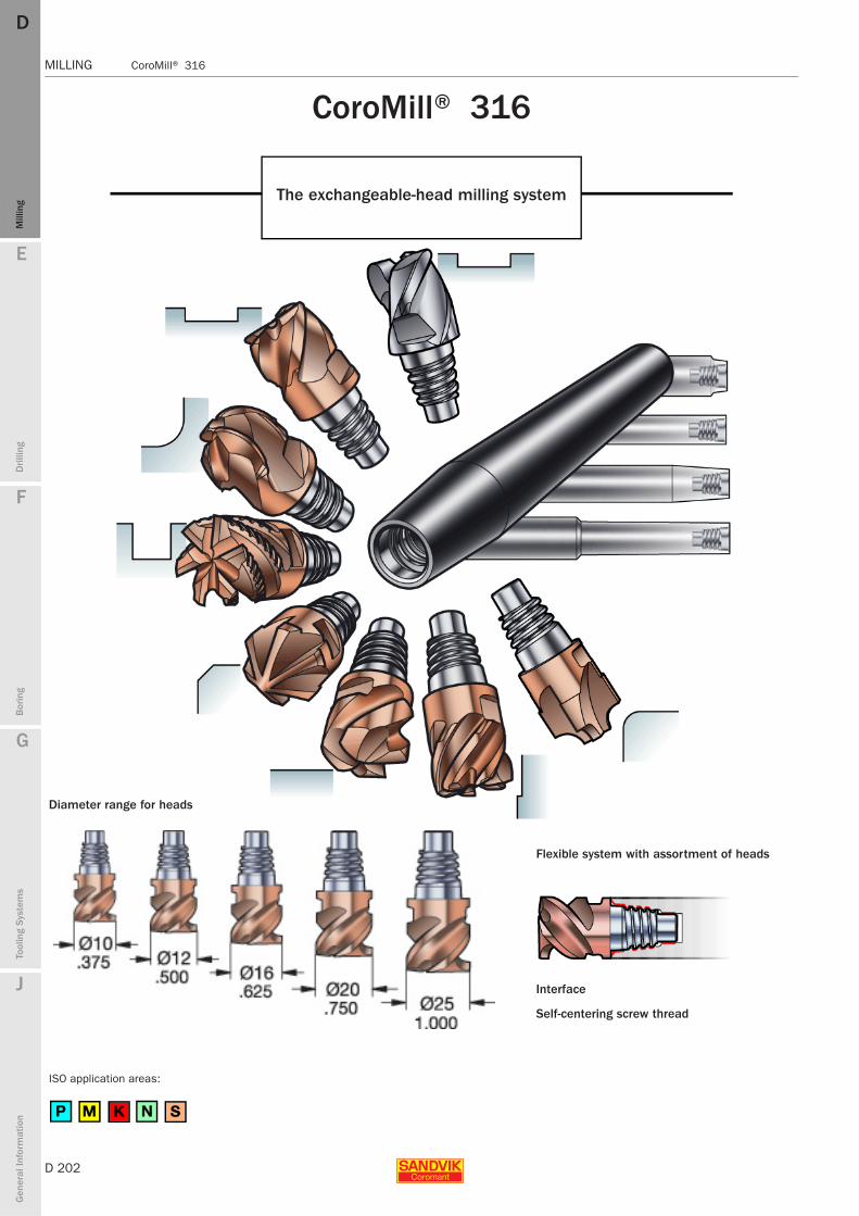
D 202
MILLING CoroMill® 316
E
Mill
ing
Drilli
ng
F
Bor
ing
G
Tool
ing
Syst
ems
J
Gen
eral
Info
rmat
ion
DDM
illin
g
MILLING CoroMill® 316
CoroMill® 316
The exchangeable-head milling system
Flexible system with assortment of heads
Diameter range for heads
Interface
Self-centering screw thread
ISO application areas:

E
D 203
Mill
ing
Drilli
ng
F
Bor
ing
G
Tool
ing
Syst
ems
J
Gen
eral
Info
rmat
ion
DD
Mill
ing
CoroMill® 316 MILLING
MILLING CoroMill® 316
Tool guide and selection
Roughing/semi - finishing Roughing, high feed Roughing Profiling FinishingFirst choice Kordell
Page D204 D207 D208 D210 D209Design Corner radius High feed cutter Kordell design Ball nose end mill Multi edge
Centre cutting Non centre cutting Centre cutting Centre cutting Non centre cuttingwith/without radius
Geometry P P K G LCutter diameter (Dc )
10-25 mm 10-25 mm 10-25 mm 10-25 mm 10-25 mm.375-1.000 inch .375-1.000 inch .375-1.000 inch .375-1.000 inch .375-1.000 inch
Corner radius (rε), dia. mm (inch)
0.5-4 mm 1.5-3 mm 0.4 mm 5-12 mm 0-1.5 mm.015-.250 inch .060-.080 inch .015-.062 inch .188-.500 inch .015-.250 inch
Application
Chamfering Chamfering Aluminium milling
Page D211 D212 D206Design Chamfer Chamfer radius Corner radius
15, 30, 45, 49, 60 Centre cutting
Geometry G G ACutter diameter (Dc )
10-16 mm 10-25 mm 10-25 mm.375-.625 inch .375-1.000 inch -
Corner radius (rε), dia. mm (inch)
No radius 1.5-8 mm 0-4 mm.062-.313 inch
Application
Shoulder milling Slot milling Face milling Axial / plunge milling
Pocket milling Ramping Profiling
Chamfering Chamfering inside Chamfering outside

D 204
MILLING CoroMill® 316
E
Mill
ing
Drilli
ng
F
Bor
ing
G
Tool
ing
Syst
ems
J
Gen
eral
Info
rmat
ion
DDM
illin
g
MILLING CoroMill® 316
Corner radius end millGeneral milling first choiceCentre cutting
Metric version
Helix angle: 50°Tolerances: Dc = h9
Dimensions, mm P M K S
Dc mm Ordering code Coupling size zn D5m l1 rε Max ap U
GC GC GC GC
1030
1030
1030
1030
10 316-10SM350-10005P E10 3 9.7 12.4 0.5 5.5 0.02 ✩ ✩ ✩ ✩
316-10SM350-10010P 3 9.7 12.4 1.0 5.5 0.02 ✩ ✩ ✩ ✩
316-10SM450-10005P 4 9.7 12.4 0.5 5.5 0.02 ✩ ✩ ✩ ✩
316-10SM450-10010P 4 9.7 12.4 1.0 5.5 0.02 ✩ ✩ ✩ ✩
316-10SM450-10015P 4 9.7 12.4 1.5 5.5 0.02 ✩ ✩ ✩ ✩
316-10SM450-10020P 4 9.7 12.4 2.0 5.5 0.02 ✩ ✩ ✩ ✩
316-10SM450-10030P 4 9.7 12.4 3.0 5.5 0.02 ✩ ✩ ✩ ✩
12 316-12SM350-12005P E12 3 11.7 14.5 0.5 6.5 0.04 ✩ ✩ ✩ ✩
316-12SM350-12010P 3 11.7 14.5 1.0 6.5 0.04 ✩ ✩ ✩ ✩
316-12SM450-12005P 4 11.7 14.5 0.5 6.5 0.04 ✩ ✩ ✩ ✩
316-12SM450-12010P 4 11.7 14.5 1.0 6.5 0.04 ✩ ✩ ✩ ✩
316-12SM450-12015P 4 11.7 14.5 1.5 6.5 0.04 ✩ ✩ ✩ ✩
316-12SM450-12020P 4 11.7 14.5 2.0 6.5 0.04 ✩ ✩ ✩ ✩
316-12SM450-12030P 4 11.7 14.5 3.0 6.5 0.04 ✩ ✩ ✩ ✩
316-12SM450-12040P 4 11.7 14.5 4.0 6.5 0.04 ✩ ✩ ✩ ✩
16 316-16SM350-16005P E16 3 15.5 18.7 0.5 8.5 0.07 ✩ ✩ ✩ ✩
316-16SM350-16010P 3 15.5 18.7 1.0 8.5 0.07 ✩ ✩ ✩ ✩
316-16SM450-16005P 4 15.5 18.7 0.5 8.5 0.07 ✩ ✩ ✩ ✩
316-16SM450-16010P 4 15.5 18.7 1.0 8.5 0.07 ✩ ✩ ✩ ✩
316-16SM450-16015P 4 15.5 18.7 1.5 8.5 0.07 ✩ ✩ ✩ ✩
316-16SM450-16020P 4 15.5 18.7 2.0 8.5 0.07 ✩ ✩ ✩ ✩
316-16SM450-16030P 4 15.5 18.7 3.0 8.5 0.07 ✩ ✩ ✩ ✩
316-16SM450-16040P 4 15.5 18.7 4.0 8.5 0.07 ✩ ✩ ✩ ✩
20 316-20SM350-20005P E20 3 19.3 21.3 0.5 11.0 0.13 ✩ ✩ ✩ ✩
316-20SM350-20010P 3 19.3 21.3 1.0 11.0 0.13 ✩ ✩ ✩ ✩
316-20SM450-20005P 4 19.3 21.3 0.5 11.0 0.13 ✩ ✩ ✩ ✩
316-20SM450-20010P 4 19.3 21.3 1.0 11.0 0.13 ✩ ✩ ✩ ✩
316-20SM450-20015P 4 19.3 21.3 1.5 11.0 0.13 ✩ ✩ ✩ ✩
316-20SM450-20020P 4 19.3 21.3 2.0 11.0 0.13 ✩ ✩ ✩ ✩
316-20SM450-20030P 4 19.3 21.3 3.0 11.0 0.13 ✩ ✩ ✩ ✩
316-20SM450-20040P 4 19.3 21.3 4.0 11.0 0.13 ✩ ✩ ✩ ✩
25 316-25SM550-25010P E25 5 24.2 25.6 1.0 13.5 0.21 ✩ ✩ ✩ ✩
316-25SM550-25015P 5 24.2 25.6 1.5 13.5 0.21 ✩ ✩ ✩ ✩
316-25SM550-25020P 5 24.2 25.6 2.0 13.5 0.21 ✩ ✩ ✩ ✩
zn = number of cutting edges
D213 J2 G93
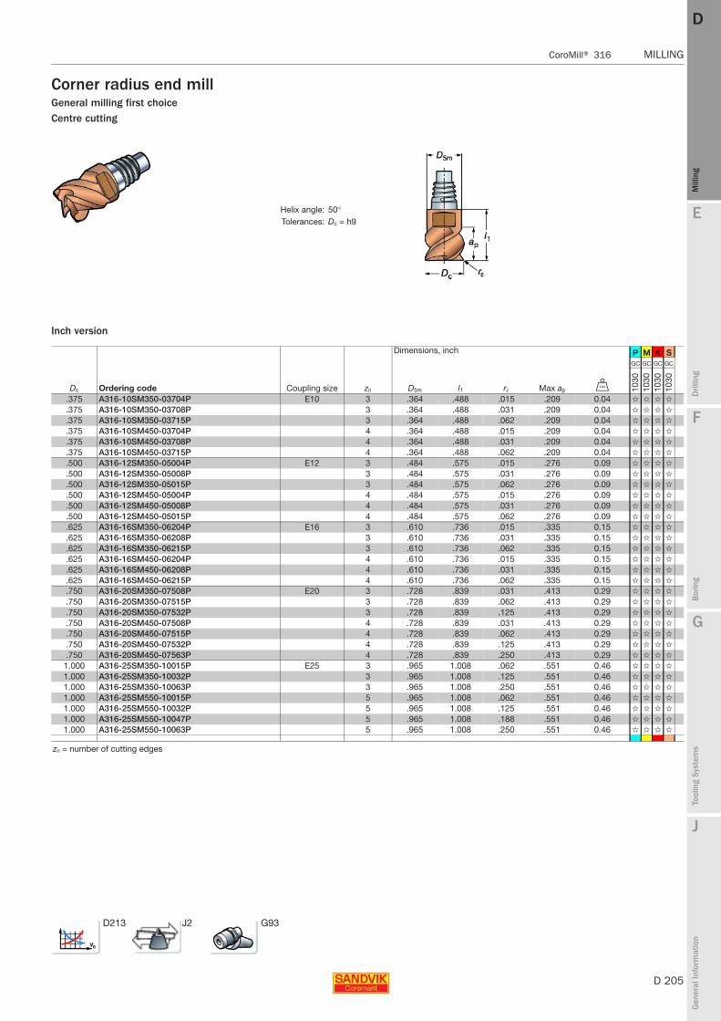
E
D 205
Mill
ing
Drilli
ng
F
Bor
ing
G
Tool
ing
Syst
ems
J
Gen
eral
Info
rmat
ion
DD
Mill
ing
CoroMill® 316 MILLING
MILLING CoroMill® 316
Corner radius end millGeneral milling first choiceCentre cutting
Inch version
Helix angle: 50°Tolerances: Dc = h9
Dimensions, inch P M K S
Dc Ordering code Coupling size zn D5m l1 rε Max ap V
GC GC GC GC
1030
1030
1030
1030
.375 A316-10SM350-03704P E10 3 .364 .488 .015 .209 0.04 ✩ ✩ ✩ ✩
.375 A316-10SM350-03708P 3 .364 .488 .031 .209 0.04 ✩ ✩ ✩ ✩
.375 A316-10SM350-03715P 3 .364 .488 .062 .209 0.04 ✩ ✩ ✩ ✩
.375 A316-10SM450-03704P 4 .364 .488 .015 .209 0.04 ✩ ✩ ✩ ✩
.375 A316-10SM450-03708P 4 .364 .488 .031 .209 0.04 ✩ ✩ ✩ ✩
.375 A316-10SM450-03715P 4 .364 .488 .062 .209 0.04 ✩ ✩ ✩ ✩
.500 A316-12SM350-05004P E12 3 .484 .575 .015 .276 0.09 ✩ ✩ ✩ ✩
.500 A316-12SM350-05008P 3 .484 .575 .031 .276 0.09 ✩ ✩ ✩ ✩
.500 A316-12SM350-05015P 3 .484 .575 .062 .276 0.09 ✩ ✩ ✩ ✩
.500 A316-12SM450-05004P 4 .484 .575 .015 .276 0.09 ✩ ✩ ✩ ✩
.500 A316-12SM450-05008P 4 .484 .575 .031 .276 0.09 ✩ ✩ ✩ ✩
.500 A316-12SM450-05015P 4 .484 .575 .062 .276 0.09 ✩ ✩ ✩ ✩
.625 A316-16SM350-06204P E16 3 .610 .736 .015 .335 0.15 ✩ ✩ ✩ ✩
.625 A316-16SM350-06208P 3 .610 .736 .031 .335 0.15 ✩ ✩ ✩ ✩
.625 A316-16SM350-06215P 3 .610 .736 .062 .335 0.15 ✩ ✩ ✩ ✩
.625 A316-16SM450-06204P 4 .610 .736 .015 .335 0.15 ✩ ✩ ✩ ✩
.625 A316-16SM450-06208P 4 .610 .736 .031 .335 0.15 ✩ ✩ ✩ ✩
.625 A316-16SM450-06215P 4 .610 .736 .062 .335 0.15 ✩ ✩ ✩ ✩
.750 A316-20SM350-07508P E20 3 .728 .839 .031 .413 0.29 ✩ ✩ ✩ ✩
.750 A316-20SM350-07515P 3 .728 .839 .062 .413 0.29 ✩ ✩ ✩ ✩
.750 A316-20SM350-07532P 3 .728 .839 .125 .413 0.29 ✩ ✩ ✩ ✩
.750 A316-20SM450-07508P 4 .728 .839 .031 .413 0.29 ✩ ✩ ✩ ✩
.750 A316-20SM450-07515P 4 .728 .839 .062 .413 0.29 ✩ ✩ ✩ ✩
.750 A316-20SM450-07532P 4 .728 .839 .125 .413 0.29 ✩ ✩ ✩ ✩
.750 A316-20SM450-07563P 4 .728 .839 .250 .413 0.29 ✩ ✩ ✩ ✩
1.000 A316-25SM350-10015P E25 3 .965 1.008 .062 .551 0.46 ✩ ✩ ✩ ✩
1.000 A316-25SM350-10032P 3 .965 1.008 .125 .551 0.46 ✩ ✩ ✩ ✩
1.000 A316-25SM350-10063P 3 .965 1.008 .250 .551 0.46 ✩ ✩ ✩ ✩
1.000 A316-25SM550-10015P 5 .965 1.008 .062 .551 0.46 ✩ ✩ ✩ ✩
1.000 A316-25SM550-10032P 5 .965 1.008 .125 .551 0.46 ✩ ✩ ✩ ✩
1.000 A316-25SM550-10047P 5 .965 1.008 .188 .551 0.46 ✩ ✩ ✩ ✩
1.000 A316-25SM550-10063P 5 .965 1.008 .250 .551 0.46 ✩ ✩ ✩ ✩
zn = number of cutting edges
D213 J2 G93
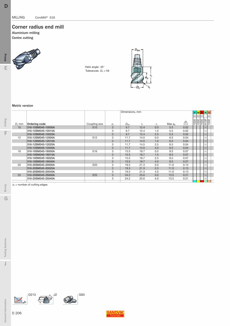
D 206
MILLING CoroMill® 316
E
Mill
ing
Drilli
ng
F
Bor
ing
G
Tool
ing
Syst
ems
J
Gen
eral
Info
rmat
ion
DDM
illin
g
MILLING CoroMill® 316
Corner radius end millAluminium millingCentre cutting
Metric version
Helix angle: 45°Tolerances: Dc = h9
Dimensions, mm P M K N S
Dc mm Ordering code Coupling size zn D5m l1 rε Max ap U
GC GC GC - GC
1030
1030
1030
H10
F10
30
10 316-10SM345-10000A E10 3 9.7 12.4 0.0 5.5 0.02 ✩
316-10SM345-10010A 3 9.7 12.4 1.0 5.5 0.02 ✩
316-10SM345-10025A 3 9.7 12.4 2.5 5.5 0.02 ✩
12 316-12SM345-12000A E12 3 11.7 14.5 0.0 6.5 0.04 ✩
316-12SM345-12010A 3 11.7 14.5 1.0 6.5 0.04 ✩
316-12SM345-12025A 3 11.7 14.5 2.5 6.5 0.04 ✩
316-12SM345-12040A 3 11.7 14.5 4.0 6.5 0.04 ✩
16 316-16SM345-16000A E16 3 15.5 18.7 0.0 8.5 0.07 ✩
316-16SM345-16015A 3 15.5 18.7 1.5 8.5 0.07 ✩
316-16SM345-16025A 3 15.5 18.7 2.5 8.5 0.07 ✩
316-16SM345-16040A 3 15.5 18.7 4.0 8.5 0.07 ✩
20 316-20SM345-20000A E20 3 19.3 21.3 0.0 11.0 0.13 ✩
316-20SM345-20025A 3 19.3 21.3 2.5 11.0 0.13 ✩
316-20SM345-20040A 3 19.3 21.3 4.0 11.0 0.13 ✩
25 316-25SM345-25000A E25 3 24.2 25.6 0.0 13.5 0.21 ✩
316-25SM345-25040A 3 24.2 25.6 4.0 13.5 0.21 ✩
zn = number of cutting edges
D213 J2 G93
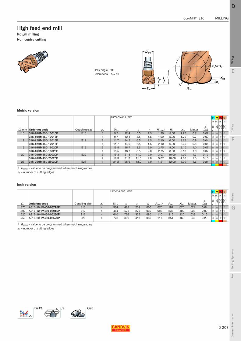
E
D 207
Mill
ing
Drilli
ng
F
Bor
ing
G
Tool
ing
Syst
ems
J
Gen
eral
Info
rmat
ion
DD
Mill
ing
CoroMill® 316 MILLING
MILLING CoroMill® 316
High feed end millRough millingNon centre cutting
Metric version
Inch version
Helix angle: 50°Tolerances: Dc = h9
Dimensions, mm P M K S
Dc mm Ordering code Coupling size zn D5m l1 l3 rε Rcomp1) Rbo Xbo Max ap U
GC GC GC GC
1030
1030
1030
1030
10 316-10HM350-10015P E10 3 9.7 12.4 5.5 1.5 1.99 5.00 1.70 0.7 0.02 ✩ ✩ ✩ ✩
316-10HM450-10015P 4 9.7 12.4 5.5 1.5 1.99 5.00 1.70 0.7 0.02 ✩ ✩ ✩ ✩
12 316-12HM350-12015P E12 3 11.7 14.5 6.5 1.5 2.10 6.00 2.25 0.8 0.04 ✩ ✩ ✩ ✩
316-12HM450-12015P 4 11.7 14.5 6.5 1.5 2.10 6.00 2.25 0.8 0.04 ✩ ✩ ✩ ✩
16 316-16HM350-16020P E16 3 15.5 18.7 8.5 2.0 2.75 8.00 3.10 1.0 0.07 ✩ ✩ ✩ ✩
316-16HM450-16020P 4 15.5 18.7 8.5 2.0 2.75 8.00 3.10 1.0 0.07 ✩ ✩ ✩ ✩
20 316-20HM350-20020P E20 3 19.3 21.3 11.0 2.0 3.07 10.00 4.00 1.3 0.13 ✩ ✩ ✩ ✩
316-20HM450-20020P 4 19.3 21.3 11.0 2.0 3.07 10.00 4.00 1.3 0.13 ✩ ✩ ✩ ✩
25 316-25HM450-25030P E25 4 24.2 25.6 13.0 3.0 4.21 12.00 5.00 1.6 0.21 ✩ ✩ ✩ ✩
1) Rcomp = value to be programmed when machining radiuszn = number of cutting edges
Dimensions, inch P M K S
Dc Ordering code Coupling size zn D5m l1 l3 rε Rcomp1) Rbo Xbo Max ap V
GC GC GC GC
1030
1030
1030
1030
.375 A316-10HM450-03715P E10 4 .364 .488 .209 .060 .076 .181 .070 .024 0.04 ✩ ✩ ✩ ✩
.500 A316-12HM450-05015P E12 4 .484 .575 .276 .060 .086 .236 .100 .033 0.09 ✩ ✩ ✩ ✩
.625 A316-16HM450-06220P E16 4 .610 .736 .335 .080 .110 .315 .120 .039 0.15 ✩ ✩ ✩ ✩
.750 A316-20HM450-07520P E20 4 .728 .839 .413 .080 .117 .354 .160 .047 0.29 ✩ ✩ ✩ ✩
1) Rcomp = value to be programmed when machining radiuszn = number of cutting edges
D213 J2 G93

D 208
MILLING CoroMill® 316
E
Mill
ing
Drilli
ng
F
Bor
ing
G
Tool
ing
Syst
ems
J
Gen
eral
Info
rmat
ion
DDM
illin
g
MILLING CoroMill® 316
Roughing end millKordellCentre cutting
Metric version
Inch version
Helix angle: 40° - 45°Tolerances: Dc = h12
Dimensions, mm P M K S
Dc mm Ordering code Coupling size zn D5m l1 rε Max ap U
GC GC GC GC
1030
1030
1030
1030
10 316-10SM440-10004K E10 4 9.7 12.4 0.4 5.5 0.02 ✩ ✩ ✩ ✩
316-10SM545-10004K 5 9.7 12.4 0.4 5.5 0.02 ✩ ✩ ✩ ✩
12 316-12SM440-12004K E12 4 11.7 14.5 0.4 6.5 0.04 ✩ ✩ ✩ ✩
316-12SM545-12004K 5 11.7 14.5 0.4 6.5 0.04 ✩ ✩ ✩ ✩
16 316-16SM440-16004K E16 4 15.5 18.7 0.4 8.5 0.07 ✩ ✩ ✩ ✩
316-16SM645-16004K 6 15.5 18.7 0.4 8.5 0.07 ✩ ✩ ✩ ✩
20 316-20SM645-20004K E20 6 19.3 21.3 0.4 11.0 0.13 ✩ ✩ ✩ ✩
25 316-25SM845-25004K E25 8 24.2 25.6 0.4 13.5 0.21 ✩ ✩ ✩ ✩
zn = number of cutting edges
Dimensions, inch P M K S
Dc Ordering code Coupling size zn D5m l1 rε Max ap V
GC GC GC GC
1030
1030
1030
1030
.375 A316-10SM440-03704K E10 4 .364 .488 .015 .209 0.04 ✩ ✩ ✩ ✩
.500 A316-12SM440-05004K E12 4 .484 .575 .015 .276 0.09 ✩ ✩ ✩ ✩
.500 A316-12SM440-05015K 4 .484 .575 .062 .276 0.09 ✩ ✩ ✩ ✩
.625 A316-16SM440-06204K E16 4 .610 .736 .015 .335 0.15 ✩ ✩ ✩ ✩
.625 A316-16SM440-06215K 4 .610 .736 .062 .335 0.15 ✩ ✩ ✩ ✩
.750 A316-20SM440-07504K E20 4 .728 .839 .015 .413 0.29 ✩ ✩ ✩ ✩
.750 A316-20SM645-07504K 6 .728 .839 .015 .413 0.29 ✩ ✩ ✩ ✩
1.000 A316-25SM845-10004K E25 8 .965 1.008 .015 .551 0.46 ✩ ✩ ✩ ✩
zn = number of cutting edges
D213 J2 G93
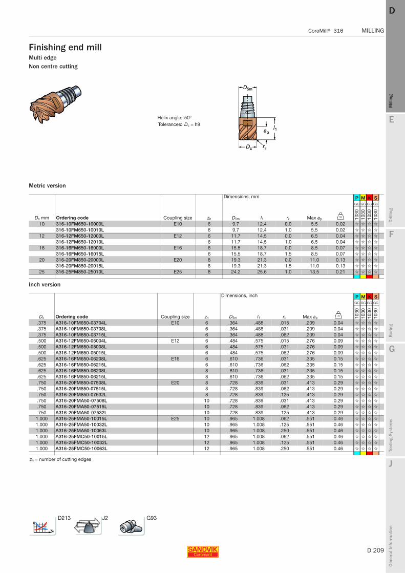
E
D 209
Mill
ing
Drilli
ng
F
Bor
ing
G
Tool
ing
Syst
ems
J
Gen
eral
Info
rmat
ion
DD
Mill
ing
CoroMill® 316 MILLING
MILLING CoroMill® 316
Finishing end millMulti edgeNon centre cutting
Metric version
Inch version
Helix angle: 50°Tolerances: Dc = h9
Dimensions, mm P M K S
Dc mm Ordering code Coupling size zn D5m l1 rε Max ap U
GC GC GC GC
1030
1030
1030
1030
10 316-10FM650-10000L E10 6 9.7 12.4 0.0 5.5 0.02 ✩ ✩ ✩ ✩
316-10FM650-10010L 6 9.7 12.4 1.0 5.5 0.02 ✩ ✩ ✩ ✩
12 316-12FM650-12000L E12 6 11.7 14.5 0.0 6.5 0.04 ✩ ✩ ✩ ✩
316-12FM650-12010L 6 11.7 14.5 1.0 6.5 0.04 ✩ ✩ ✩ ✩
16 316-16FM650-16000L E16 6 15.5 18.7 0.0 8.5 0.07 ✩ ✩ ✩ ✩
316-16FM650-16015L 6 15.5 18.7 1.5 8.5 0.07 ✩ ✩ ✩ ✩
20 316-20FM850-20000L E20 8 19.3 21.3 0.0 11.0 0.13 ✩ ✩ ✩ ✩
316-20FM850-20015L 8 19.3 21.3 1.5 11.0 0.13 ✩ ✩ ✩ ✩
25 316-25FM850-25010L E25 8 24.2 25.6 1.0 13.5 0.21 ✩ ✩ ✩ ✩
Dimensions, inch P M K S
Dc Ordering code Coupling size zn D5m l1 rε Max ap V
GC GC GC GC
1030
1030
1030
1030
.375 A316-10FM650-03704L E10 6 .364 .488 .015 .209 0.04 ✩ ✩ ✩ ✩
.375 A316-10FM650-03708L 6 .364 .488 .031 .209 0.04 ✩ ✩ ✩ ✩
.375 A316-10FM650-03715L 6 .364 .488 .062 .209 0.04 ✩ ✩ ✩ ✩
.500 A316-12FM650-05004L E12 6 .484 .575 .015 .276 0.09 ✩ ✩ ✩ ✩
.500 A316-12FM650-05008L 6 .484 .575 .031 .276 0.09 ✩ ✩ ✩ ✩
.500 A316-12FM650-05015L 6 .484 .575 .062 .276 0.09 ✩ ✩ ✩ ✩
.625 A316-16FM650-06208L E16 6 .610 .736 .031 .335 0.15 ✩ ✩ ✩ ✩
.625 A316-16FM650-06215L 6 .610 .736 .062 .335 0.15 ✩ ✩ ✩ ✩
.625 A316-16FM850-06208L 8 .610 .736 .031 .335 0.15 ✩ ✩ ✩ ✩
.625 A316-16FM850-06215L 8 .610 .736 .062 .335 0.15 ✩ ✩ ✩ ✩
.750 A316-20FM850-07508L E20 8 .728 .839 .031 .413 0.29 ✩ ✩ ✩ ✩
.750 A316-20FM850-07515L 8 .728 .839 .062 .413 0.29 ✩ ✩ ✩ ✩
.750 A316-20FM850-07532L 8 .728 .839 .125 .413 0.29 ✩ ✩ ✩ ✩
.750 A316-20FMA50-07508L 10 .728 .839 .031 .413 0.29 ✩ ✩ ✩ ✩
.750 A316-20FMA50-07515L 10 .728 .839 .062 .413 0.29 ✩ ✩ ✩ ✩
.750 A316-20FMA50-07532L 10 .728 .839 .125 .413 0.29 ✩ ✩ ✩ ✩
1.000 A316-25FMA50-10015L E25 10 .965 1.008 .062 .551 0.46 ✩ ✩ ✩ ✩
1.000 A316-25FMA50-10032L 10 .965 1.008 .125 .551 0.46 ✩ ✩ ✩ ✩
1.000 A316-25FMA50-10063L 10 .965 1.008 .250 .551 0.46 ✩ ✩ ✩ ✩
1.000 A316-25FMC50-10015L 12 .965 1.008 .062 .551 0.46 ✩ ✩ ✩ ✩
1.000 A316-25FMC50-10032L 12 .965 1.008 .125 .551 0.46 ✩ ✩ ✩ ✩
1.000 A316-25FMC50-10063L 12 .965 1.008 .250 .551 0.46 ✩ ✩ ✩ ✩
zn = number of cutting edges
D213 J2 G93

D 210
MILLING CoroMill® 316
E
Mill
ing
Drilli
ng
F
Bor
ing
G
Tool
ing
Syst
ems
J
Gen
eral
Info
rmat
ion
DDM
illin
g
MILLING CoroMill® 316
Ball nose end millProfile millingCentre cutting
Metric version
Inch version
Helix angle: 40°Tolerances: Dc = h9
Dimensions, mm P M K S
Dc2 mm Ordering code Coupling size zn D5m l1 rε Max ap U
GC GC GC GC
1030
1030
1030
1030
10 316-10BM440-10050G E10 4 9.7 12.4 5.0 5.5 0.02 ✩ ✩ ✩ ✩
12 316-12BM440-12060G E12 4 11.7 14.5 6.0 6.5 0.04 ✩ ✩ ✩ ✩
16 316-16BM440-16080G E16 4 15.5 18.7 8.0 8.5 0.07 ✩ ✩ ✩ ✩
20 316-20BM240-200AG E20 2 19.3 21.3 10.0 11.0 0.13 ✩ ✩ ✩ ✩
316-20BM440-200AG 4 19.3 21.3 10.0 11.0 0.13 ✩ ✩ ✩ ✩
25 316-25BM240-250DG E25 2 24.2 25.6 12.5 13.5 0.20 ✩ ✩ ✩ ✩
316-25BM440-250DG 4 24.2 25.6 12.5 13.5 0.21 ✩ ✩ ✩ ✩
Dimensions, inch P M K S
Dc2 Ordering code Coupling size zn D5m l1 rε Max ap V
GC GC GC GC
1030
1030
1030
1030
.375 A316-10BM440-03750G E10 4 .364 .488 .188 .209 0.04 ✩ ✩ ✩ ✩
.500 A316-12BM440-05060G E12 4 .484 .575 .250 .276 0.09 ✩ ✩ ✩ ✩
.625 A316-16BM440-06280G E16 4 .610 .736 .312 .335 0.15 ✩ ✩ ✩ ✩
.750 A316-20BM440-075AG E20 4 .728 .839 .375 .413 0.29 ✩ ✩ ✩ ✩
1.000 A316-25BM440-100CG E25 4 .965 1.008 .500 .551 0.44 ✩ ✩ ✩ ✩
zn = number of cutting edges
D213 J2 G93
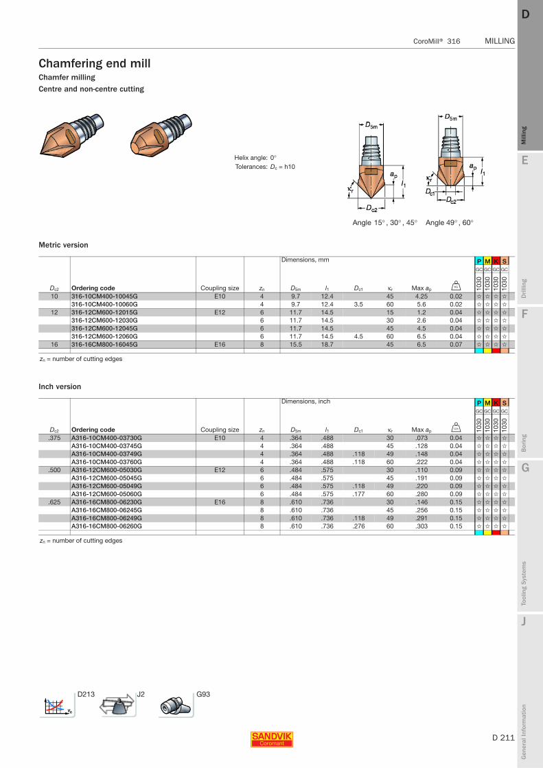
E
D 211
Mill
ing
Drilli
ng
F
Bor
ing
G
Tool
ing
Syst
ems
J
Gen
eral
Info
rmat
ion
DD
Mill
ing
CoroMill® 316 MILLING
MILLING CoroMill® 316
Chamfering end millChamfer millingCentre and non-centre cutting
Metric version
Inch version
Helix angle: 0°Tolerances: Dc = h10
Angle 15° , 30° , 45° Angle 49° , 60°
Dimensions, mm P M K S
Dc2 Ordering code Coupling size zn D5m l1 Dc1 κr Max ap U
GC GC GC GC
1030
1030
1030
1030
10 316-10CM400-10045G E10 4 9.7 12.4 45 4.25 0.02 ✩ ✩ ✩ ✩
316-10CM400-10060G 4 9.7 12.4 3.5 60 5.6 0.02 ✩ ✩ ✩ ✩
12 316-12CM600-12015G E12 6 11.7 14.5 15 1.2 0.04 ✩ ✩ ✩ ✩
316-12CM600-12030G 6 11.7 14.5 30 2.6 0.04 ✩ ✩ ✩ ✩
316-12CM600-12045G 6 11.7 14.5 45 4.5 0.04 ✩ ✩ ✩ ✩
316-12CM600-12060G 6 11.7 14.5 4.5 60 6.5 0.04 ✩ ✩ ✩ ✩
16 316-16CM800-16045G E16 8 15.5 18.7 45 6.5 0.07 ✩ ✩ ✩ ✩
zn = number of cutting edges
Dimensions, inch P M K S
Dc2 Ordering code Coupling size zn D5m l1 Dc1 κr Max ap V
GC GC GC GC
1030
1030
1030
1030
.375 A316-10CM400-03730G E10 4 .364 .488 30 .073 0.04 ✩ ✩ ✩ ✩
A316-10CM400-03745G 4 .364 .488 45 .128 0.04 ✩ ✩ ✩ ✩
A316-10CM400-03749G 4 .364 .488 .118 49 .148 0.04 ✩ ✩ ✩ ✩
A316-10CM400-03760G 4 .364 .488 .118 60 .222 0.04 ✩ ✩ ✩ ✩
.500 A316-12CM600-05030G E12 6 .484 .575 30 .110 0.09 ✩ ✩ ✩ ✩
A316-12CM600-05045G 6 .484 .575 45 .191 0.09 ✩ ✩ ✩ ✩
A316-12CM600-05049G 6 .484 .575 .118 49 .220 0.09 ✩ ✩ ✩ ✩
A316-12CM600-05060G 6 .484 .575 .177 60 .280 0.09 ✩ ✩ ✩ ✩
.625 A316-16CM800-06230G E16 8 .610 .736 30 .146 0.15 ✩ ✩ ✩ ✩
A316-16CM800-06245G 8 .610 .736 45 .256 0.15 ✩ ✩ ✩ ✩
A316-16CM800-06249G 8 .610 .736 .118 49 .291 0.15 ✩ ✩ ✩ ✩
A316-16CM800-06260G 8 .610 .736 .276 60 .303 0.15 ✩ ✩ ✩ ✩
zn = number of cutting edges
D213 J2 G93
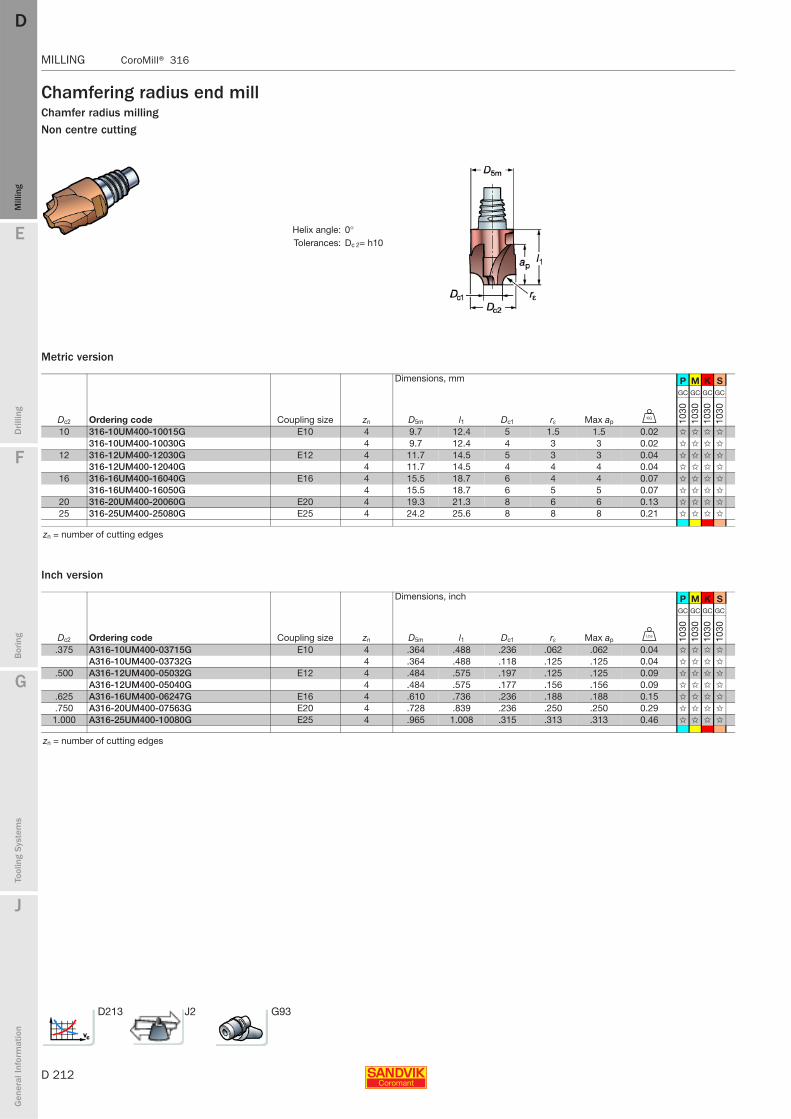
D 212
MILLING CoroMill® 316
E
Mill
ing
Drilli
ng
F
Bor
ing
G
Tool
ing
Syst
ems
J
Gen
eral
Info
rmat
ion
DDM
illin
g
MILLING CoroMill® 316
Chamfering radius end millChamfer radius millingNon centre cutting
Metric version
Inch version
Helix angle: 0°Tolerances: Dc 2= h10
Dimensions, mm P M K S
Dc2 Ordering code Coupling size zn D5m l1 Dc1 rε Max ap U
GC GC GC GC
1030
1030
1030
1030
10 316-10UM400-10015G E10 4 9.7 12.4 5 1.5 1.5 0.02 ✩ ✩ ✩ ✩
316-10UM400-10030G 4 9.7 12.4 4 3 3 0.02 ✩ ✩ ✩ ✩
12 316-12UM400-12030G E12 4 11.7 14.5 5 3 3 0.04 ✩ ✩ ✩ ✩
316-12UM400-12040G 4 11.7 14.5 4 4 4 0.04 ✩ ✩ ✩ ✩
16 316-16UM400-16040G E16 4 15.5 18.7 6 4 4 0.07 ✩ ✩ ✩ ✩
316-16UM400-16050G 4 15.5 18.7 6 5 5 0.07 ✩ ✩ ✩ ✩
20 316-20UM400-20060G E20 4 19.3 21.3 8 6 6 0.13 ✩ ✩ ✩ ✩
25 316-25UM400-25080G E25 4 24.2 25.6 8 8 8 0.21 ✩ ✩ ✩ ✩
zn = number of cutting edges
Dimensions, inch P M K S
Dc2 Ordering code Coupling size zn D5m l1 Dc1 rε Max ap V
GC GC GC GC
1030
1030
1030
1030
.375 A316-10UM400-03715G E10 4 .364 .488 .236 .062 .062 0.04 ✩ ✩ ✩ ✩
A316-10UM400-03732G 4 .364 .488 .118 .125 .125 0.04 ✩ ✩ ✩ ✩
.500 A316-12UM400-05032G E12 4 .484 .575 .197 .125 .125 0.09 ✩ ✩ ✩ ✩
A316-12UM400-05040G 4 .484 .575 .177 .156 .156 0.09 ✩ ✩ ✩ ✩
.625 A316-16UM400-06247G E16 4 .610 .736 .236 .188 .188 0.15 ✩ ✩ ✩ ✩
.750 A316-20UM400-07563G E20 4 .728 .839 .236 .250 .250 0.29 ✩ ✩ ✩ ✩
1.000 A316-25UM400-10080G E25 4 .965 1.008 .315 .313 .313 0.46 ✩ ✩ ✩ ✩
zn = number of cutting edges
D213 J2 G93
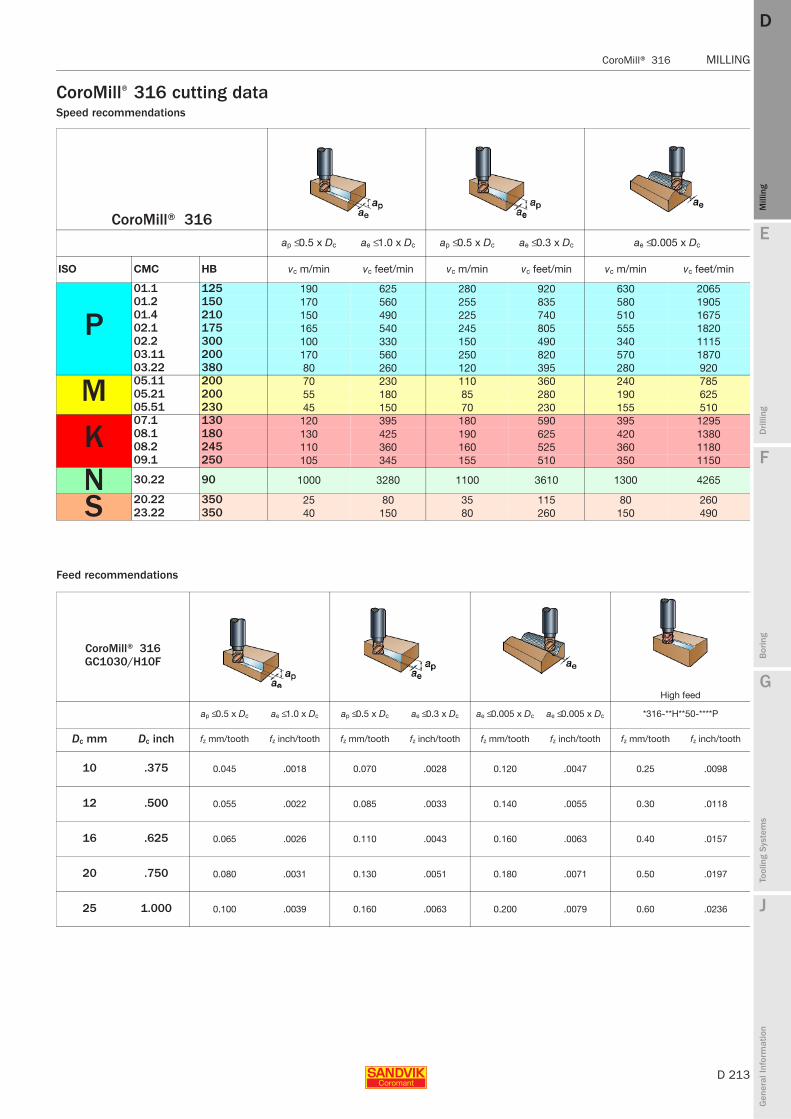
E
D 213
Mill
ing
Drilli
ng
F
Bor
ing
G
Tool
ing
Syst
ems
J
Gen
eral
Info
rmat
ion
DD
Mill
ing
CoroMill® 316 MILLING
MILLING CoroMill® 316
CoroMill® 316 cutting dataSpeed recommendations
Feed recommendations
CoroMill® 316ap ≤ 0.5 x Dc ae ≤ 1.0 x Dc ap ≤ 0.5 x Dc ae ≤ 0.3 x Dc ae ≤ 0.005 x Dc
ISO CMC HB vc m/min vc feet/min vc m/min vc feet/min vc m/min vc feet/min
P01.1 125 190 625 280 920 630 206501.2 150 170 560 255 835 580 190501.4 210 150 490 225 740 510 167502.1 175 165 540 245 805 555 182002.2 300 100 330 150 490 340 111503.11 200 170 560 250 820 570 187003.22 380 80 260 120 395 280 920
M 05.11 200 70 230 110 360 240 78505.21 200 55 180 85 280 190 62505.51 230 45 150 70 230 155 510
K07.1 130 120 395 180 590 395 129508.1 180 130 425 190 625 420 138008.2 245 110 360 160 525 360 118009.1 250 105 345 155 510 350 1150
N 30.22 90 1000 3280 1100 3610 1300 4265
S 20.22 350 25 80 35 115 80 26023.22 350 40 150 80 260 150 490
CoroMill® 316GC1030/H10F
High feed
ap ≤ 0.5 x Dc ae ≤ 1.0 x Dc ap ≤ 0.5 x Dc ae ≤ 0.3 x Dc ae ≤ 0.005 x Dc ae ≤ 0.005 x Dc *316-**H**50-****P
Dc mm Dc inch fz mm/tooth fz inch/tooth fz mm/tooth fz inch/tooth fz mm/tooth fz inch/tooth fz mm/tooth fz inch/tooth
10 .375 0.045 .0018 0.070 .0028 0.120 .0047 0.25 .0098
12 .500 0.055 .0022 0.085 .0033 0.140 .0055 0.30 .0118
16 .625 0.065 .0026 0.110 .0043 0.160 .0063 0.40 .0157
20 .750 0.080 .0031 0.130 .0051 0.180 .0071 0.50 .0197
25 1.000 0.100 .0039 0.160 .0063 0.200 .0079 0.60 .0236
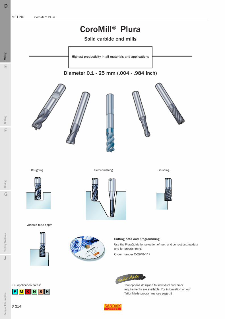
D 214
MILLING CoroMill® Plura
E
Mill
ing
Drilli
ng
F
Bor
ing
G
Tool
ing
Syst
ems
J
Gen
eral
Info
rmat
ion
DDM
illin
g
MILLING CoroMill® Plura
CoroMill® Plura Solid carbide end mills
Highest productivity in all materials and applications
Diameter 0.1 - 25 mm (.004 - .984 inch)
ISO application areas:
Cutting data and programming
Use the PluraGuide for selection of tool, and correct cutting data and for programming
Order number C-2948-117
Roughing Semi-finishing Finishing
Variable flute depth
Tool options designed to individual customer requirements are available. For information on our Tailor Made programme see page J3.
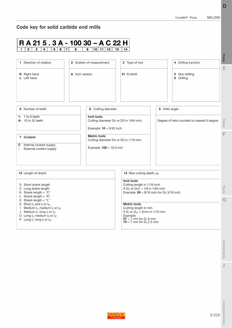
E
D 215
Mill
ing
Drilli
ng
F
Bor
ing
G
Tool
ing
Syst
ems
J
Gen
eral
Info
rmat
ion
DD
Mill
ing
CoroMill® Plura MILLING
MILLING CoroMill® Plura
Code key for solid carbide end mills
1 Direction of rotation 2 System of measurement 3 Type of tool 4 Drilling function
R Right hand A Inch version 21 Endmill 5 Non drillingL Left hand 6 Drilling
6 Number of teeth
1- 1 to 9 teethA- 10 to 32 teeth
7 Coolant
C Internal coolant supply- External coolant supply
8 Cutting diameter
Inch toolsCutting diameter Dc or D3 in 1/64 inch.
Example: 10 = 5/32 inch
Metric toolsCutting diameter Dc or D3 in 1/10 mm.
Example: 100 = 10.0 mm
9 Helix angle
Degree of helix rounded to nearest 5 degree
12 Length of shank
S Short shank lengthC Long shank lengthK Shank length > "C"L Shank length > "K"X Shank length > "L"E Short l2 and l3 or l22
I Medium l2, medium l3 or l22
J Medium l2, long l3 or l22
O Long l2, medium l3 or l22
P Long l2, long l3 or l22
13 Max cutting depth, ap
Inch toolsCutting length in 1/16 inchIf Dc or Dc2 < 1/8 in 1/64 inchExample: 09 = 9/16 inch for Dc 3/16 inch
Metric toolsCutting length in mmIf Dc or Dc2 < 3mm in 1/10 mmExample:07 = 7 mm for Dc 6 mm70 = 7 mm for Dc 2.5 mm

D 216
MILLING CoroMill® Plura
E
Mill
ing
Drilli
ng
F
Bor
ing
G
Tool
ing
Syst
ems
J
Gen
eral
Info
rmat
ion
DDM
illin
g
MILLING CoroMill® Plura
5 Basic design of end mill
0 Concave chamfer end mill 6 Full radius (ball nose) with spherical form1 Square form with/without corner chamfer, tight tolerance at Dc 7 Conical straight form2 Square form with corner radius 8 45° chamfer end mill3 Square form with/without corner chamfer 9 30° chamfer end mill4 Full radius (ball nose) form (6 or less teeth) H High feed end mill5 Conical full radius (ball nose) form (6 or less teeth) T Turn-mill end mill
10 Corner radius/Conical angle
Corner radius Conical angleMetric tools Inch tools Metric tools– No radius – No radius – No radius/AngleA <0.5 mm A 1/64 inch M 0.5°B 0.5 mm B 1/32 inch N 1°C 1.0 mm C 3/64 inch O 1.5°D 1.5 mm D 1/16 inch P 2°E 2.0 mm E 5/64 inch Q 2.5°F 2.5 mm F 3/32 inch R 3°etc. etc. S 3.5°
T 4°etc.
11 Shank type
A Cylindrical
B Weldon
C Cylindrical with neck
E-J Cylindrical with neck (Neck length/Dc, mm)
E = 0.1 - 1.9 H = 6.0 - 7.9
F = 2.0 - 3.9 I = 8.0 - 9.9
G = 4.0 - 5.9 J = 10 - 11.9
14 Geometry type
Cutting edge TW % of Dc or Dc2 Rake angle γ °K Kordell 50-60 9° -12°B Chip breaker 60 4° -7°U Kordell <50 9° -12°A Straight <45 12° -15°P Straight 45-55 9° -12°N Straight 56-65 9° -12°L Straight 66-75 4° -12°G Straight 50-75 -3° -3°H Straight >75 <-3°
TW = Core diameter
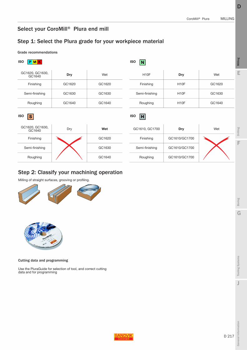
E
D 217
Mill
ing
Drilli
ng
F
Bor
ing
G
Tool
ing
Syst
ems
J
Gen
eral
Info
rmat
ion
DD
Mill
ing
CoroMill® Plura MILLING
MILLING CoroMill® Plura
Select your CoroMill® Plura end mill
Cutting data and programming
Use the PluraGuide for selection of tool, and correct cutting data and for programming
Step 2: Classify your machining operationMilling of straight surfaces, grooving or profiling.
Grade recommendations
ISO ISO
GC1620, GC1630, GC1640 Dry Wet H10F Dry Wet
Finishing GC1620 GC1620 Finishing H10F GC1620
Semi-finishing GC1630 GC1630 Semi-finishing H10F GC1630
Roughing GC1640 GC1640 Roughing H10F GC1640
ISO ISO
GC1620, GC1630, GC1640 Dry Wet GC1610, GC1700 Dry Wet
Finishing GC1620 Finishing GC1610/GC1700
Semi-finishing GC1630 Semi-finishing GC1610/GC1700
Roughing GC1640 Roughing GC1610/GC1700
Step 1: Select the Plura grade for your workpiece material
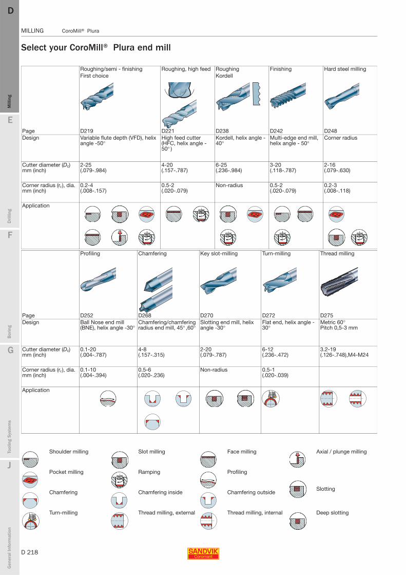
D 218
MILLING CoroMill® Plura
E
Mill
ing
Drilli
ng
F
Bor
ing
G
Tool
ing
Syst
ems
J
Gen
eral
Info
rmat
ion
DDM
illin
g
MILLING CoroMill® Plura
Select your CoroMill® Plura end mill
Roughing/semi - finishing Roughing, high feed Roughing Finishing Hard steel millingFirst choice Kordell
Page D219 D221 D238 D242 D248Design Variable flute depth (VFD), helix
angle -50°High feed cutter (HFC, helix angle -50° )
Kordell, helix angle -40°
Multi-edge end mill, helix angle - 50°
Corner radius
Cutter diameter (Dc) mm (inch)
2-25(.079-.984)
4-20(.157-.787)
6-25(.236-.984)
3-20(.118-.787)
2-16(.079-.630)
Corner radius (rε), dia. mm (inch)
0.2-4(.008-.157)
0.5-2(.020-.079)
Non-radius 0.5-2(.020-.079)
0.2-3(.008-.118)
Application
Profiling Chamfering Key slot-milling Turn-milling Thread milling
Page D252 D268 D270 D272 D275Design Ball Nose end mill
(BNE), helix angle -30°Chamfering/chamfering radius end mill, 45° ,60°
Slotting end mill, helix angle -30°
Flat end, helix angle -30°
Metric 60°Pitch 0,5-3 mm
Cutter diameter (Dc) mm (inch)
0.1-20(.004-.787)
4-8(.157-.315)
2-20(.079-.787)
6-12(.236-.472)
3.2-19(.126-.748),M4-M24
Corner radius (rε), dia. mm (inch)
0.1-10(.004-.394)
0.5-6(.020-.236)
Non-radius 0.5-1(.020-.039)
Application
Shoulder milling Slot milling Face milling Axial / plunge milling
Pocket milling Ramping Profiling
SlottingChamfering Chamfering inside Chamfering outside
Turn-milling Thread milling, external Thread milling, internal Deep slotting
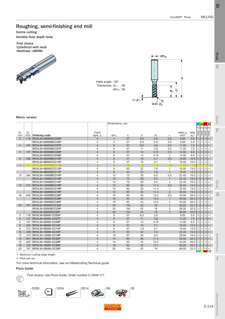
E
D 219
Mill
ing
Drilli
ng
F
Bor
ing
G
Tool
ing
Syst
ems
J
Gen
eral
Info
rmat
ion
DD
Mill
ing
CoroMill® Plura MILLING
MILLING CoroMill® Plura
Roughing, semi-finishing end millCentre cuttingVariable flute depth tools
Metric version
Plura Guide
First choice Cylindrical with neckHardness ≤ 48HRc
Helix angle: -50°Tolerances: Dc : h9
dmm : h6
Dimensions, mm P M K S
Dc mm
Dc inch Ordering code
Front type, zn dmm l2 l3 d4 rε
Helix lsh mm2)
Max ap1)
GC GC GC GC
1640
1640
1640
1640
3 .118 R216.24-03050ACC05P 4 4 57 8.5 2.9 0.2 8.00 5.0 ✩ ✩ ✩ ✩
R216.24-03050BCC05P 4 4 57 8.5 2.9 0.5 8.00 5.0 ✩ ✩ ✩ ✩
4 .157 R216.24-04050ACC07P 4 6 57 8.5 3.8 0.2 11.20 7.0 ✩ ✩ ✩ ✩
R216.24-04050BCC07P 4 6 57 11 3.8 0.5 11.20 7.0 ✩ ✩ ✩ ✩
5 .197 R216.24-05050BCC08P 4 6 57 14 4.75 0.5 14.00 8.0 ✩ ✩ ✩ ✩
R216.24-05050CCC08P 4 6 57 14 4.75 1 14.00 8.0 ✩ ✩ ✩ ✩
6 .236 R216.24-06050BCC10P 4 6 57 16 5.7 0.5 16.00 10.0 ✩ ✩ ✩ ✩
R216.24-06050CCC10P 4 6 57 16 5.7 1 16.00 10.0 ✩ ✩ ✩ ✩
8 .315 R216.24-08050BCC13P 4 8 63 22 7.6 0.5 16.00 13.0 ✩ ✩ ✩ ✩
R216.24-08050CCC13P 4 8 63 22 7.6 1 16.00 13.0 ✩ ✩ ✩ ✩
R216.24-08050ECC13P 4 8 63 22 7.6 2 16.00 13.0 ✩ ✩ ✩ ✩
10 .394 R216.24-10050BCC16P 4 10 72 28 9.5 0.5 22.40 16.0 ✩ ✩ ✩ ✩
R216.24-10050CCC16P 4 10 72 28 9.5 1 22.40 16.0 ✩ ✩ ✩ ✩
R216.24-10050ECC16P 4 10 72 28 9.5 2 22.40 16.0 ✩ ✩ ✩ ✩
12 .472 R216.24-12050BCC19P 4 12 83 33 11.4 0.5 35.50 19.0 ✩ ✩ ✩ ✩
R216.24-12050CCC19P 4 12 83 33 11.4 1 35.50 19.0 ✩ ✩ ✩ ✩
R216.24-12050ECC19P 4 12 83 33 11.4 2 35.50 19.0 ✩ ✩ ✩ ✩
16 .630 R216.24-16050BCC26P 4 16 92 42 15.2 0.5 45.00 26.0 ✩ ✩ ✩ ✩
R216.24-16050CCC26P 4 16 92 42 15.2 1 45.00 26.0 ✩ ✩ ✩ ✩
R216.24-16050ECC26P 4 16 92 42 15.2 2 45.00 26.0 ✩ ✩ ✩ ✩
20 .787 R216.24-20050CCC32P 4 20 104 52 19 1 56.00 32.0 ✩ ✩ ✩ ✩
R216.24-20050ECC32P 4 20 104 52 19 2 56.00 32.0 ✩ ✩ ✩ ✩
R216.24-20050ICC32P 4 20 104 52 19 4 56.00 32.0 ✩ ✩ ✩ ✩
3 .118 R216.34-03050-CC05P 4 6 57 8.5 2.9 8.00 0.5 ✩ ✩ ✩ ✩
4 .157 R216.34-04050-CC07P 4 6 57 11 3.8 11.20 7.0 ✩ ✩ ✩ ✩
5 .197 R216.34-05050-CC08P 4 6 57 14 4.75 14.00 8.0 ✩ ✩ ✩ ✩
6 .236 R216.34-06050-CC10P 4 6 57 16 5.7 16.00 10.0 ✩ ✩ ✩ ✩
8 .315 R216.34-08050-CC13P 4 6 57 7.6 5.7 16.00 13.0 ✩ ✩ ✩ ✩
10 ..393 R216.34-10050-CC16P 4 8 63 22 7.6 22.40 16.0 ✩ ✩ ✩ ✩
12 ..472 R216.34-12050-CC19P 4 10 57 28 9.5 28.00 19.0 ✩ ✩ ✩ ✩
14 .551 R216.34-14050-CC22P 4 14 83 36 11.4 35.50 22.0 ✩ ✩ ✩ ✩
16 .630 R216.34-16050-CC26P 4 16 92 42 15.2 45.00 26.0 ✩ ✩ ✩ ✩
18 .709 R216.34-18050-CC29P 4 18 92 42 17.1 56.00 29.0 ✩ ✩ ✩ ✩
20 .787 R216.34-20050-CC32P 4 20 104 52 19 56.00 32.0 ✩ ✩ ✩ ✩
1) Maximum cutting edge length.2) Pitch per rev.
For more technical information, see our Metalcutting Technical guide
First choice: Use Plura Guide. Order number C-2948-117
D328 D334 D214 G6 D2
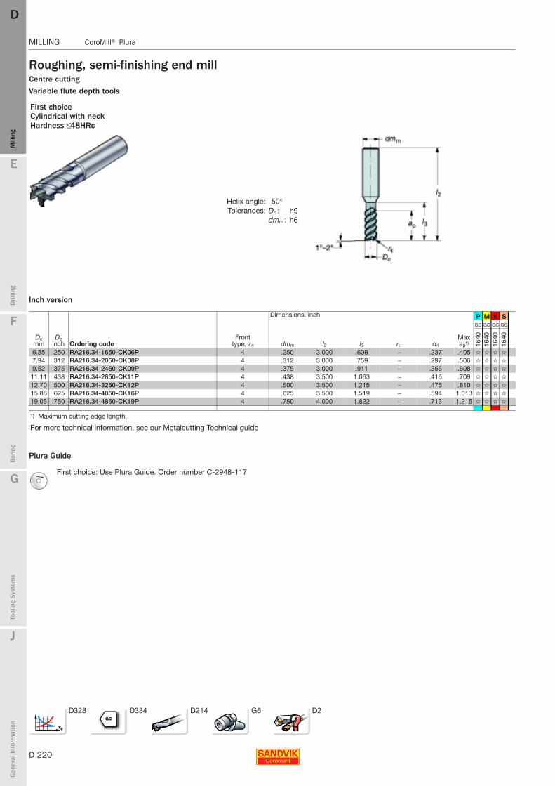
D 220
MILLING CoroMill® Plura
E
Mill
ing
Drilli
ng
F
Bor
ing
G
Tool
ing
Syst
ems
J
Gen
eral
Info
rmat
ion
DDM
illin
g
MILLING CoroMill® Plura
Roughing, semi-finishing end millCentre cuttingVariable flute depth tools
Inch version
Plura Guide
First choice Cylindrical with neckHardness ≤ 48HRc
Helix angle: -50°Tolerances: Dc : h9
dmm : h6
Dimensions, inch P M K S
Dc mm
Dc inch Ordering code
Front type, zn dmm l2 l3 rε d4
Max ap1)
GC GC GC GC
1640
1640
1640
1640
6.35 .250 RA216.34-1650-CK06P 4 .250 3.000 .608 − .237 .405 ✩ ✩ ✩ ✩
7.94 .312 RA216.34-2050-CK08P 4 .312 3.000 .759 − .297 .506 ✩ ✩ ✩ ✩
9.52 .375 RA216.34-2450-CK09P 4 .375 3.000 .911 − .356 .608 ✩ ✩ ✩ ✩
11.11 .438 RA216.34-2850-CK11P 4 .438 3.500 1.063 − .416 .709 ✩ ✩ ✩ ✩
12.70 .500 RA216.34-3250-CK12P 4 .500 3.500 1.215 − .475 .810 ✩ ✩ ✩ ✩
15.88 .625 RA216.34-4050-CK16P 4 .625 3.500 1.519 − .594 1.013 ✩ ✩ ✩ ✩
19.05 .750 RA216.34-4850-CK19P 4 .750 4.000 1.822 − .713 1.215 ✩ ✩ ✩ ✩
1) Maximum cutting edge length.
For more technical information, see our Metalcutting Technical guide
First choice: Use Plura Guide. Order number C-2948-117
D328 D334 D214 G6 D2

E
D 221
Mill
ing
Drilli
ng
F
Bor
ing
G
Tool
ing
Syst
ems
J
Gen
eral
Info
rmat
ion
DD
Mill
ing
CoroMill® Plura MILLING
MILLING CoroMill® Plura
High feed end mill
Non centre cutting
Metric version
Plura Guide
Hardness 43≤HRc≤63
Helix angle: -50°Tolerances: Dc : h9
dmm : h6
Dimensions, mm P M K S H
Dc mm
Dc inch Ordering code
Front type, zn dmm l2 l3 rε Rcomp1) Rbo Xbo
Max ap
GC GC GC GC GC
1620
1620
1620
1620
1610
Cylindrical shank4 .157 R215.H4-04050BAC01H 4 6 57 11 0.5 0.620 4.0 0.6 0.1 ✩
6 .236 R215.H4-06050BAC02H 4 6 57 15 0.5 0.690 9.0 0.7 0.2 ✩
8 .315 R215.H4-08050CAC02H 4 8 63 20 1 1.230 12.0 0.78 0.2 ✩
10 .394 R215.H4-10050DAC03H 4 10 72 26 1.5 1.770 15.0 0.8 0.3 ✩
12 .472 R215.H4-12050DAC04H 4 12 30 30 1.5 1.880 18.0 1 0.4 ✩
16 .630 R215.H4-16050EAC05H 4 16 92 36 2 2.460 24.0 1.5 0.5 ✩
20 .787 R215.H4-20050EAC06H 4 20 104 45 2 2.610 30.0 2.2 0.6 ✩
4 .157 R215.H4-04050BAC02P 4 6 57 11 0.5 0.670 2.0 0.8 0.2 ✩ ✩ ✩ ✩
6 .236 R215.H4-06050BAC03P 4 6 57 15 0.5 0.750 3.0 1.4 0.3 ✩ ✩ ✩ ✩
8 .315 R215.H4-08050CAC05P 4 8 63 20 1 1.380 4.0 1.54 0.5 ✩ ✩ ✩ ✩
10 .394 R215.H4-10050DAC07P 4 10 72 26 1.5 1.990 5.0 1.7 0.7 ✩ ✩ ✩ ✩
12 .472 R215.H4-12050DAC08P 4 12 83 30 1.5 2.100 6.0 2.25 0.8 ✩ ✩ ✩ ✩
16 .630 R215.H4-16050EAC10P 4 16 92 36 2 2.750 8.0 3.1 1.0 ✩ ✩ ✩ ✩
20 .787 R215.H4-20050EAC13P 4 20 104 45 2 3.070 10.0 4 1.3 ✩ ✩ ✩ ✩
6 .236 R215.H4-06050BAK02P 4 6 100 15 0.5 0.750 3.0 1.4 0.2 ✩ ✩ ✩ ✩
8 .315 R215.H4-08050CAK02P 4 8 120 20 1 1.380 4.0 1.54 0.2 ✩ ✩ ✩ ✩
10 .394 R215.H4-10050DAK03P 4 10 150 26 1.5 1.990 5.0 1.7 0.3 ✩ ✩ ✩ ✩
12 .472 R215.H4-12050DAK08P 4 12 93 30 1.5 2.100 6.0 2.25 0.8 ✩ ✩ ✩ ✩
16 .630 R215.H4-16050EAK10P 4 16 112 36 2 2.747 8.0 3.1 1.0 ✩ ✩ ✩ ✩
20 .787 R215.H4-20050EAK13P 4 20 130 45 2 3.072 10.0 4 1.3 ✩ ✩ ✩ ✩
1) Rcomp = value to be programmed when machining radius
For more technical information, see our Metalcutting Technical guide
First choice: Use Plura Guide. Order number C-2948-117
D328 D334 D214 G6 D2

D 222
MILLING CoroMill® Plura
E
Mill
ing
Drilli
ng
F
Bor
ing
G
Tool
ing
Syst
ems
J
Gen
eral
Info
rmat
ion
DDM
illin
g
MILLING CoroMill® Plura
Roughing, semi-finishing end millCentre cuttingVariable flute depth tools
Metric version
Inch version
Plura Guide
First choice Cylindrical with neckHardness ≤ 48HRc
Helix angle: 45°Tolerances: Dc : h9
dmm : h6
Dimensions, mm P M K S
Dc mm
Dc inch Ordering code
Front type, zn dmm l2 l3 d4 rε
Helix lsh mm2)
Max ap1)
GC GC GC GC
1640
1640
1640
1640
2 .079 R216.23-02045ACC05P 3 6 57 7.5 1.92 0.08 5.60 5.0 ✩ ✩ ✩ ✩
3 .118 R216.23-03045ACC07P 3 6 57 10.5 2.9 0.08 8.00 7.0 ✩ ✩ ✩ ✩
4 .157 R216.23-04045ACC09P 3 6 57 13.5 3.8 0.16 11.20 9.0 ✩ ✩ ✩ ✩
5 .197 R216.23-05045ACC11P 3 6 57 16.5 4.75 0.16 14.00 11.0 ✩ ✩ ✩ ✩
6 .236 R216.23-06045ACC13P 3 6 57 19.5 5.7 0.16 16.00 13.0 ✩ ✩ ✩ ✩
8 .315 R216.23-08045ACC18P 3 8 63 25 7.6 0.16 22.40 18.0 ✩ ✩ ✩ ✩
10 .394 R216.23-10045ACC22P 3 10 72 30 9.5 0.25 28.00 22.0 ✩ ✩ ✩ ✩
12 .472 R216.23-12045ACC26P 3 12 83 36 11.4 0.25 35.00 26.0 ✩ ✩ ✩ ✩
16 .630 R216.23-16045ACC34P 3 16 92 42 15.2 0.25 45.00 34.0 ✩ ✩ ✩ ✩
20 .787 R216.23-20045ACC42P 3 20 104 52 15.2 0.4 56.00 42.0 ✩ ✩ ✩ ✩
2 .079 R216.33-02045-CC05P 3 6 57 7.5 1.92 6.30 5.0 ✩ ✩ ✩ ✩
3 .118 R216.33-03045-CC07P 3 6 57 10.5 2.9 10.00 7.0 ✩ ✩ ✩ ✩
4 .157 R216.33-04045-CC09P 3 6 57 15 3.8 12.50 9.0 ✩ ✩ ✩ ✩
5 .197 R216.33-05045-CC11P 3 6 57 16 4.75 16.00 11.0 ✩ ✩ ✩ ✩
6 .236 R216.33-06045-CC13P 3 6 57 19 5.7 20.00 13.0 ✩ ✩ ✩ ✩
8 .315 R216.33-08045-CC18P 3 8 63 25 7.6 25.00 18.0 ✩ ✩ ✩ ✩
10 .394 R216.33-10045-CC22P 3 10 72 30 9.5 31.50 22.0 ✩ ✩ ✩ ✩
12 .472 R216.33-12045-CC26P 3 12 83 36 11.4 40.00 26.0 ✩ ✩ ✩ ✩
16 .630 R216.33-16045-CC34P 3 16 92 42 15.2 50.00 34.0 ✩ ✩ ✩ ✩
20 .787 R216.33-20045-CC42P 3 20 104 52 19 63.00 42.0 ✩ ✩ ✩ ✩
Dimensions, inch P M K S
Dc mm
Dc inch Ordering code
Front type, zn dmm l2 l3 d4
Max ap1)
GC GC GC GC
1640
1640
1640
1640
1.59 .062 RA216.33-0445-CK03P 3 .062 2.000 .246 .059 .164 ✩ ✩ ✩ ✩
2.38 .094 RA216.33-0645-CK03P 3 .094 2.500 .341 .089 .227 ✩ ✩ ✩ ✩
3.18 .125 RA216.33-0845-CK04P 3 .125 2.500 .434 .118 .289 ✩ ✩ ✩ ✩
4.76 .188 RA216.33-1245-CK06P 3 .188 2.500 .622 .178 .414 ✩ ✩ ✩ ✩
6.35 .250 RA216.33-1645-CK08P 3 .250 3.000 .809 .237 .539 ✩ ✩ ✩ ✩
7.94 .312 RA216.33-2045-CK10P 3 .312 3.000 .996 .297 .664 ✩ ✩ ✩ ✩
9.52 .375 RA216.33-2445-CK13P 3 .375 3.000 1.243 .356 .829 ✩ ✩ ✩ ✩
11.11 .438 RA216.33-2845-CK15P 3 .438 3.500 1.431 .416 .954 ✩ ✩ ✩ ✩
12.70 .500 RA216.33-3245-CK17P 3 .500 3.500 1.431 .475 1.079 ✩ ✩ ✩ ✩
15.88 .625 RA216.33-4045-CK21P 3 .625 3.500 1.535 .594 1.329 ✩ ✩ ✩ ✩
19.05 .750 RA216.33-4845-CK25P 3 .750 4.000 1.890 .713 1.579 ✩ ✩ ✩ ✩
1) Maximum cutting edge length.2) Pitch per rev.
For more technical information, see our Metalcutting Technical guide
First choice: Use Plura Guide. Order number C-2948-117
D328 D334 D214 G6 D2
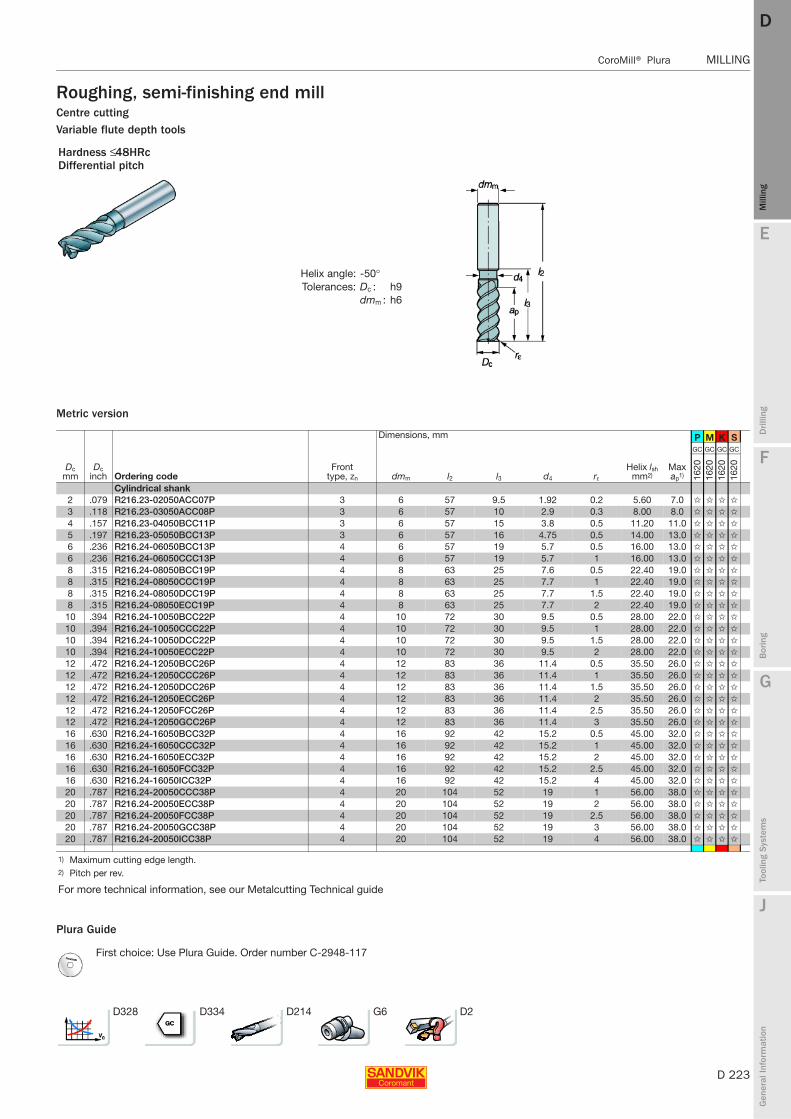
E
D 223
Mill
ing
Drilli
ng
F
Bor
ing
G
Tool
ing
Syst
ems
J
Gen
eral
Info
rmat
ion
DD
Mill
ing
CoroMill® Plura MILLING
MILLING CoroMill® Plura
Roughing, semi-finishing end millCentre cuttingVariable flute depth tools
Metric version
Plura Guide
Hardness ≤ 48HRcDifferential pitch
Helix angle: -50°Tolerances: Dc : h9
dmm : h6
Dimensions, mm P M K S
Dc mm
Dc inch Ordering code
Front type, zn dmm l2 l3 d4 rε
Helix lsh mm2)
Max ap1)
GC GC GC GC
1620
1620
1620
1620
Cylindrical shank2 .079 R216.23-02050ACC07P 3 6 57 9.5 1.92 0.2 5.60 7.0 ✩ ✩ ✩ ✩
3 .118 R216.23-03050ACC08P 3 6 57 10 2.9 0.3 8.00 8.0 ✩ ✩ ✩ ✩
4 .157 R216.23-04050BCC11P 3 6 57 15 3.8 0.5 11.20 11.0 ✩ ✩ ✩ ✩
5 .197 R216.23-05050BCC13P 3 6 57 16 4.75 0.5 14.00 13.0 ✩ ✩ ✩ ✩
6 .236 R216.24-06050BCC13P 4 6 57 19 5.7 0.5 16.00 13.0 ✩ ✩ ✩ ✩
6 .236 R216.24-06050CCC13P 4 6 57 19 5.7 1 16.00 13.0 ✩ ✩ ✩ ✩
8 .315 R216.24-08050BCC19P 4 8 63 25 7.6 0.5 22.40 19.0 ✩ ✩ ✩ ✩
8 .315 R216.24-08050CCC19P 4 8 63 25 7.7 1 22.40 19.0 ✩ ✩ ✩ ✩
8 .315 R216.24-08050DCC19P 4 8 63 25 7.7 1.5 22.40 19.0 ✩ ✩ ✩ ✩
8 .315 R216.24-08050ECC19P 4 8 63 25 7.7 2 22.40 19.0 ✩ ✩ ✩ ✩
10 .394 R216.24-10050BCC22P 4 10 72 30 9.5 0.5 28.00 22.0 ✩ ✩ ✩ ✩
10 .394 R216.24-10050CCC22P 4 10 72 30 9.5 1 28.00 22.0 ✩ ✩ ✩ ✩
10 .394 R216.24-10050DCC22P 4 10 72 30 9.5 1.5 28.00 22.0 ✩ ✩ ✩ ✩
10 .394 R216.24-10050ECC22P 4 10 72 30 9.5 2 28.00 22.0 ✩ ✩ ✩ ✩
12 .472 R216.24-12050BCC26P 4 12 83 36 11.4 0.5 35.50 26.0 ✩ ✩ ✩ ✩
12 .472 R216.24-12050CCC26P 4 12 83 36 11.4 1 35.50 26.0 ✩ ✩ ✩ ✩
12 .472 R216.24-12050DCC26P 4 12 83 36 11.4 1.5 35.50 26.0 ✩ ✩ ✩ ✩
12 .472 R216.24-12050ECC26P 4 12 83 36 11.4 2 35.50 26.0 ✩ ✩ ✩ ✩
12 .472 R216.24-12050FCC26P 4 12 83 36 11.4 2.5 35.50 26.0 ✩ ✩ ✩ ✩
12 .472 R216.24-12050GCC26P 4 12 83 36 11.4 3 35.50 26.0 ✩ ✩ ✩ ✩
16 .630 R216.24-16050BCC32P 4 16 92 42 15.2 0.5 45.00 32.0 ✩ ✩ ✩ ✩
16 .630 R216.24-16050CCC32P 4 16 92 42 15.2 1 45.00 32.0 ✩ ✩ ✩ ✩
16 .630 R216.24-16050ECC32P 4 16 92 42 15.2 2 45.00 32.0 ✩ ✩ ✩ ✩
16 .630 R216.24-16050FCC32P 4 16 92 42 15.2 2.5 45.00 32.0 ✩ ✩ ✩ ✩
16 .630 R216.24-16050ICC32P 4 16 92 42 15.2 4 45.00 32.0 ✩ ✩ ✩ ✩
20 .787 R216.24-20050CCC38P 4 20 104 52 19 1 56.00 38.0 ✩ ✩ ✩ ✩
20 .787 R216.24-20050ECC38P 4 20 104 52 19 2 56.00 38.0 ✩ ✩ ✩ ✩
20 .787 R216.24-20050FCC38P 4 20 104 52 19 2.5 56.00 38.0 ✩ ✩ ✩ ✩
20 .787 R216.24-20050GCC38P 4 20 104 52 19 3 56.00 38.0 ✩ ✩ ✩ ✩
20 .787 R216.24-20050ICC38P 4 20 104 52 19 4 56.00 38.0 ✩ ✩ ✩ ✩
1) Maximum cutting edge length.2) Pitch per rev.
For more technical information, see our Metalcutting Technical guide
First choice: Use Plura Guide. Order number C-2948-117
D328 D334 D214 G6 D2

D 224
MILLING CoroMill® Plura
E
Mill
ing
Drilli
ng
F
Bor
ing
G
Tool
ing
Syst
ems
J
Gen
eral
Info
rmat
ion
DDM
illin
g
MILLING CoroMill® Plura
Roughing, semi-finishing end millCentre cuttingVariable flute depth tools
Metric version
Plura Guide
Hardness ≤ 48HRc
Helix angle: -50°Tolerances: Dc : h10/h9
dmm : h6
Dimensions, mm P M K S
Dc mm
Dc inch Ordering code
Front type, zn dmm l1 l2 ch1 bn rε
Helix lsh mm2)
Max ap1)
GC GC GC GC GC GC GC GC GC GC GC GC
1620
1630
1640
1620
1630
1640
1620
1630
1640
1620
1630
1640
Cylindrical shank with radius4 .157 R216.23-04050CAK11P 3 6 57 1 11.20 11.0 ✩ ✩ ✩ ✩ ✩ ✩ ✩ ✩
5 .197 R216.23-05050CAK13P 3 6 57 1 14.00 13.0 ✩ ✩ ✩ ✩ ✩ ✩ ✩ ✩
6 .236 R216.24-06050CAK13P 4 6 65 1 16.00 13.0 ✩ ✩ ✩ ✩ ✩ ✩ ✩ ✩
8 .315 R216.24-08050EAK19P 4 8 80 2 22.40 19.0 ✩ ✩ ✩ ✩ ✩ ✩ ✩ ✩
10 .394 R216.24-10050EAK22P 4 10 100 2 28.00 22.0 ✩ ✩ ✩ ✩ ✩ ✩ ✩ ✩
12 .472 R216.24-12050GAK26P 4 12 100 3 35.50 26.0 ✩ ✩ ✩ ✩ ✩ ✩ ✩ ✩
14 .551 R216.24-14050GAK26P 4 14 104 3 40.00 26.0 ✩ ✩ ✩ ✩ ✩ ✩ ✩ ✩
16 .630 R216.24-16050IAK32P 4 16 115 4 45.00 32.0 ✩ ✩ ✩ ✩ ✩ ✩ ✩ ✩
20 .787 R216.24-20050IAK38P 4 20 125 4 56.00 38.0 ✩ ✩ ✩ ✩ ✩ ✩ ✩ ✩
Cylindrical shank4 .157 R216.33-04050-AK11P 3 6 57 0.10 0.25 11.20 11.0 ✩ ✩ ✩ ✩ ✩ ✩ ✩ ✩
5 .197 R216.33-05050-AK13P 3 6 57 0.10 0.25 14.00 13.0 ✩ ✩ ✩ ✩ ✩ ✩ ✩ ✩
6 .236 R216.34-06050-AK13P 4 6 65 0.10 0.25 16.00 13.0 ✩ ✩ ✩ ✩ ✩ ✩ ✩ ✩
8 .315 R216.34-08050-AK19P 4 8 80 0.10 0.25 22.40 19.0 ✩ ✩ ✩ ✩ ✩ ✩ ✩ ✩
10 .394 R216.34-10050-AK22P 4 10 100 0.10 0.25 28.00 22.0 ✩ ✩ ✩ ✩ ✩ ✩ ✩ ✩
12 .472 R216.34-12050-AK26P 4 12 100 0.10 0.25 35.50 26.0 ✩ ✩ ✩ ✩ ✩ ✩ ✩ ✩
14 .551 R216.34-14050-AK26P 4 14 104 0.15 0.35 40.00 26.0 ✩ ✩ ✩ ✩ ✩ ✩ ✩ ✩
16 .630 R216.34-16050-AK32P 4 16 115 0.15 0.35 45.00 32.0 ✩ ✩ ✩ ✩ ✩ ✩ ✩ ✩
20 .787 R216.34-20050-AK38P 4 20 125 0.15 0.35 56.00 38.0 ✩ ✩ ✩ ✩ ✩ ✩ ✩ ✩
Weldon with radius6 .236 R216.24-06050CBC13P 4 6 39 57 1 16.00 13.0 ✩ ✩ ✩ ✩ ✩ ✩ ✩ ✩
8 .315 R216.24-08050EBC19P 4 8 45 63 2 22.40 19.0 ✩ ✩ ✩ ✩ ✩ ✩ ✩ ✩
10 .394 R216.24-10050EBC22P 4 10 52 72 2 28.00 22.0 ✩ ✩ ✩ ✩ ✩ ✩ ✩ ✩
12 .472 R216.24-12050GBC26P 4 12 61 83 3 35.50 26.0 ✩ ✩ ✩ ✩ ✩ ✩ ✩ ✩
14 .551 R216.24-14050GBC26P 4 14 61 83 3 40.00 26.0 ✩ ✩ ✩ ✩ ✩ ✩ ✩ ✩
16 .630 R216.24-16050IBC32P 4 16 68 92 4 45.00 32.0 ✩ ✩ ✩ ✩ ✩ ✩ ✩ ✩
20 .787 R216.24-20050IBC38P 4 20 79 104 4 56.00 38.0 ✩ ✩ ✩ ✩ ✩ ✩ ✩ ✩
Weldon6 .236 R216.34-06050-BC13P 4 6 39 57 0.10 0.25 16.00 13.0 ✩ ✩ ✩ ✩ ✩ ✩ ✩ ✩ ✩ ✩ ✩ ✩
8 .315 R216.34-08050-BC19P 4 8 45 63 0.10 0.25 22.40 19.0 ✩ ✩ ✩ ✩ ✩ ✩ ✩ ✩ ✩ ✩ ✩ ✩
10 .394 R216.34-10050-BC22P 4 10 52 72 0.10 0.25 28.00 22.0 ✩ ✩ ✩ ✩ ✩ ✩ ✩ ✩ ✩ ✩ ✩ ✩
12 .472 R216.34-12050-BC26P 4 12 61 83 0.10 0.25 35.50 26.0 ✩ ✩ ✩ ✩ ✩ ✩ ✩ ✩ ✩ ✩ ✩ ✩
14 .551 R216.34-14050-BC26P 4 14 61 83 0.12 0.35 40.00 26.0 ✩ ✩ ✩ ✩ ✩ ✩ ✩ ✩ ✩ ✩ ✩ ✩
16 .630 R216.34-16050-BC32P 4 16 68 92 0.12 0.35 45.00 32.0 ✩ ✩ ✩ ✩ ✩ ✩ ✩ ✩ ✩ ✩ ✩ ✩
20 .787 R216.34-20050-BC38P 4 20 79 104 0.12 0.35 56.00 38.0 ✩ ✩ ✩ ✩ ✩ ✩ ✩ ✩ ✩ ✩ ✩ ✩
1) Maximum cutting edge length.2) Pitch per rev.
For more technical information, see our Metalcutting Technical guide
First choice: Use Plura Guide. Order number C-2948-117
D328 D334 D214 G6 D2
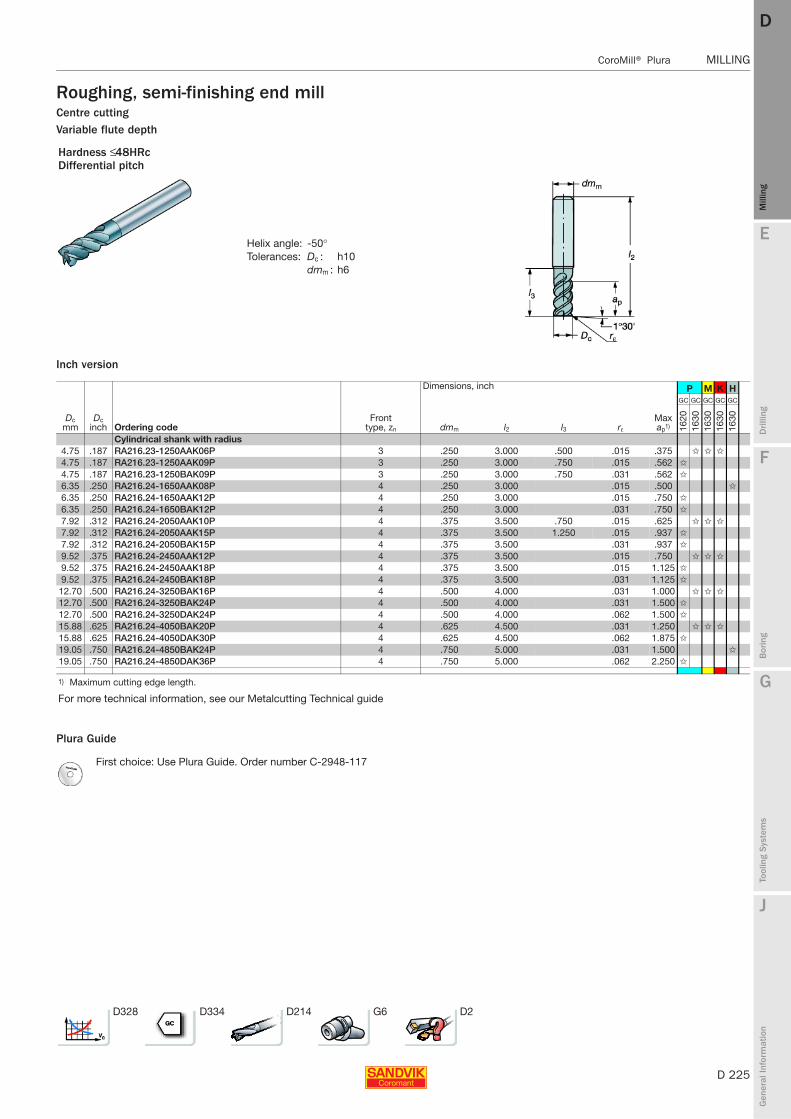
E
D 225
Mill
ing
Drilli
ng
F
Bor
ing
G
Tool
ing
Syst
ems
J
Gen
eral
Info
rmat
ion
DD
Mill
ing
CoroMill® Plura MILLING
MILLING CoroMill® Plura
Roughing, semi-finishing end millCentre cuttingVariable flute depth
Inch version
Plura Guide
Hardness ≤ 48HRcDifferential pitch
Helix angle: -50°Tolerances: Dc : h10
dmm : h6
Dimensions, inch P M K H
Dc mm
Dc inch Ordering code
Front type, zn dmm l2 l3 rε
Max ap1)
GC GC GC GC GC
1620
1630
1630
1630
1630
Cylindrical shank with radius4.75 .187 RA216.23-1250AAK06P 3 .250 3.000 .500 .015 .375 ✩ ✩ ✩
4.75 .187 RA216.23-1250AAK09P 3 .250 3.000 .750 .015 .562 ✩
4.75 .187 RA216.23-1250BAK09P 3 .250 3.000 .750 .031 .562 ✩
6.35 .250 RA216.24-1650AAK08P 4 .250 3.000 .015 .500 ✩
6.35 .250 RA216.24-1650AAK12P 4 .250 3.000 .015 .750 ✩
6.35 .250 RA216.24-1650BAK12P 4 .250 3.000 .031 .750 ✩
7.92 .312 RA216.24-2050AAK10P 4 .375 3.500 .750 .015 .625 ✩ ✩ ✩
7.92 .312 RA216.24-2050AAK15P 4 .375 3.500 1.250 .015 .937 ✩
7.92 .312 RA216.24-2050BAK15P 4 .375 3.500 .031 .937 ✩
9.52 .375 RA216.24-2450AAK12P 4 .375 3.500 .015 .750 ✩ ✩ ✩
9.52 .375 RA216.24-2450AAK18P 4 .375 3.500 .015 1.125 ✩
9.52 .375 RA216.24-2450BAK18P 4 .375 3.500 .031 1.125 ✩
12.70 .500 RA216.24-3250BAK16P 4 .500 4.000 .031 1.000 ✩ ✩ ✩
12.70 .500 RA216.24-3250BAK24P 4 .500 4.000 .031 1.500 ✩
12.70 .500 RA216.24-3250DAK24P 4 .500 4.000 .062 1.500 ✩
15.88 .625 RA216.24-4050BAK20P 4 .625 4.500 .031 1.250 ✩ ✩ ✩
15.88 .625 RA216.24-4050DAK30P 4 .625 4.500 .062 1.875 ✩
19.05 .750 RA216.24-4850BAK24P 4 .750 5.000 .031 1.500 ✩
19.05 .750 RA216.24-4850DAK36P 4 .750 5.000 .062 2.250 ✩
1) Maximum cutting edge length.
For more technical information, see our Metalcutting Technical guide
First choice: Use Plura Guide. Order number C-2948-117
D328 D334 D214 G6 D2
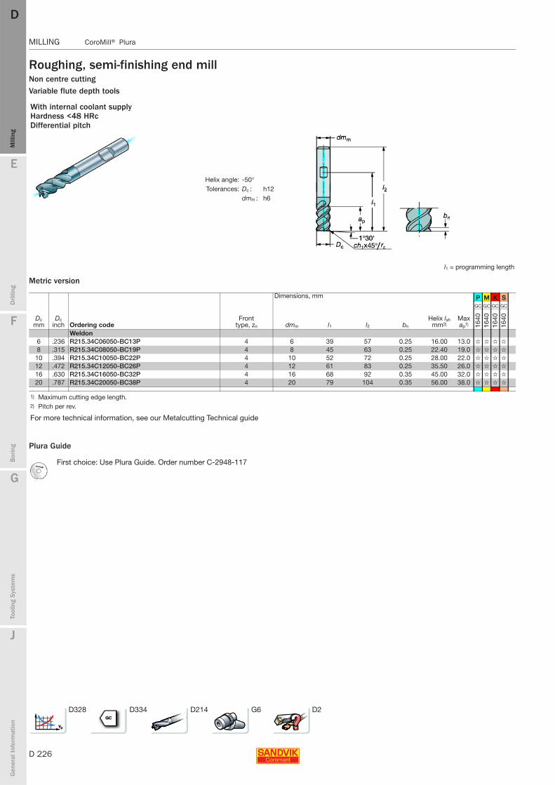
D 226
MILLING CoroMill® Plura
E
Mill
ing
Drilli
ng
F
Bor
ing
G
Tool
ing
Syst
ems
J
Gen
eral
Info
rmat
ion
DDM
illin
g
MILLING CoroMill® Plura
Roughing, semi-finishing end millNon centre cuttingVariable flute depth tools
Metric version
Plura Guide
With internal coolant supplyHardness <48 HRcDifferential pitch
Helix angle: -50°Tolerances: Dc : h12
dmm : h6
l1 = programming length
Dimensions, mm P M K S
Dc mm
Dc inch Ordering code
Front type, zn dmm l1 l2 bn
Helix lsh mm2)
Max ap1)
GC GC GC GC
1640
1640
1640
1640
Weldon6 .236 R215.34C06050-BC13P 4 6 39 57 0.25 16.00 13.0 ✩ ✩ ✩ ✩
8 .315 R215.34C08050-BC19P 4 8 45 63 0.25 22.40 19.0 ✩ ✩ ✩ ✩
10 .394 R215.34C10050-BC22P 4 10 52 72 0.25 28.00 22.0 ✩ ✩ ✩ ✩
12 .472 R215.34C12050-BC26P 4 12 61 83 0.25 35.50 26.0 ✩ ✩ ✩ ✩
16 .630 R215.34C16050-BC32P 4 16 68 92 0.35 45.00 32.0 ✩ ✩ ✩ ✩
20 .787 R215.34C20050-BC38P 4 20 79 104 0.35 56.00 38.0 ✩ ✩ ✩ ✩
1) Maximum cutting edge length.2) Pitch per rev.
For more technical information, see our Metalcutting Technical guide
First choice: Use Plura Guide. Order number C-2948-117
D328 D334 D214 G6 D2
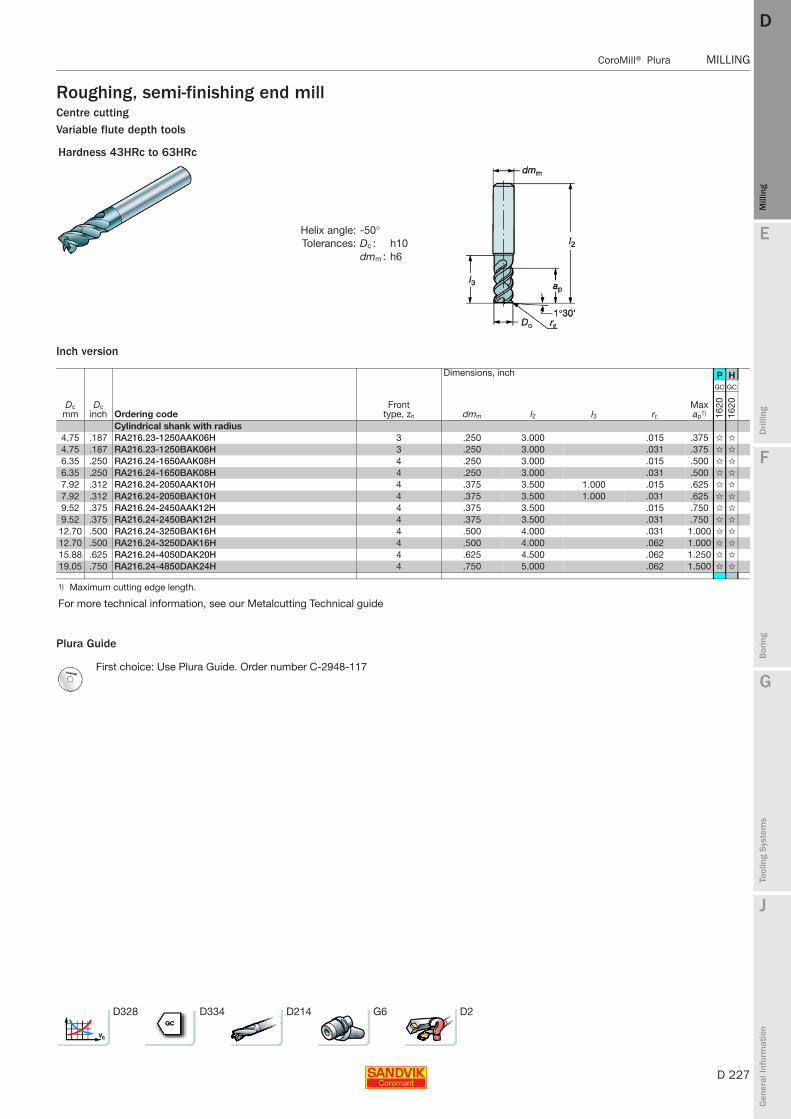
E
D 227
Mill
ing
Drilli
ng
F
Bor
ing
G
Tool
ing
Syst
ems
J
Gen
eral
Info
rmat
ion
DD
Mill
ing
CoroMill® Plura MILLING
MILLING CoroMill® Plura
Roughing, semi-finishing end millCentre cuttingVariable flute depth tools
Inch version
Plura Guide
Hardness 43HRc to 63HRc
Helix angle: -50°Tolerances: Dc : h10
dmm : h6
Dimensions, inch P H
Dc mm
Dc inch Ordering code
Front type, zn dmm l2 l3 rε
Max ap1)
GC GC
1620
1620
Cylindrical shank with radius4.75 .187 RA216.23-1250AAK06H 3 .250 3.000 .015 .375 ✩ ✩
4.75 .187 RA216.23-1250BAK06H 3 .250 3.000 .031 .375 ✩ ✩
6.35 .250 RA216.24-1650AAK08H 4 .250 3.000 .015 .500 ✩ ✩
6.35 .250 RA216.24-1650BAK08H 4 .250 3.000 .031 .500 ✩ ✩
7.92 .312 RA216.24-2050AAK10H 4 .375 3.500 1.000 .015 .625 ✩ ✩
7.92 .312 RA216.24-2050BAK10H 4 .375 3.500 1.000 .031 .625 ✩ ✩
9.52 .375 RA216.24-2450AAK12H 4 .375 3.500 .015 .750 ✩ ✩
9.52 .375 RA216.24-2450BAK12H 4 .375 3.500 .031 .750 ✩ ✩
12.70 .500 RA216.24-3250BAK16H 4 .500 4.000 .031 1.000 ✩ ✩
12.70 .500 RA216.24-3250DAK16H 4 .500 4.000 .062 1.000 ✩ ✩
15.88 .625 RA216.24-4050DAK20H 4 .625 4.500 .062 1.250 ✩ ✩
19.05 .750 RA216.24-4850DAK24H 4 .750 5.000 .062 1.500 ✩ ✩
1) Maximum cutting edge length.
For more technical information, see our Metalcutting Technical guide
First choice: Use Plura Guide. Order number C-2948-117
D328 D334 D214 G6 D2

D 228
MILLING CoroMill® Plura
E
Mill
ing
Drilli
ng
F
Bor
ing
G
Tool
ing
Syst
ems
J
Gen
eral
Info
rmat
ion
DDM
illin
g
MILLING CoroMill® Plura
Roughing, semi-finishing end millCentre cuttingVariable flute depth tools
Metric version
Plura Guide
Hardness 43≤HRc≤63
Helix angle: -50°Tolerances: Dc : h8
dmm : h6
Dimensions, mm P M K S H
Dc mm
Dc inch Ordering code
Front type, zn dmm l2 ch1 bn rε
Helix lsh mm2)
Max ap1)
GC GC GC GC GC
1620
1620
1620
1620
1620
Cylindrical shank with radius2 .079 R216.23-02050BAK70H 3 6 57 0.5 5.60 7.0 ✩ ✩ ✩ ✩ ✩
3 .118 R216.23-03050BAK08H 3 6 57 0.5 8.00 8.0 ✩ ✩
4 .157 R216.23-04050CAK11H 3 6 57 1 11.20 11.0 ✩ ✩
5 .197 R216.23-05050CAK13H 3 6 57 1 14.00 13.0 ✩ ✩
6 .236 R216.24-06050CAK13H 4 6 65 1 16.00 13.0 ✩ ✩
8 .315 R216.24-08050EAK19H 4 8 80 2 22.40 19.0 ✩ ✩
10 .394 R216.24-10050EAK22H 4 10 100 2 28.00 22.0 ✩ ✩
12 .472 R216.24-12050GAK26H 4 12 100 3 35.50 26.0 ✩ ✩
14 .551 R216.24-14050GAK26H 4 14 104 3 40.00 26.0 ✩ ✩
16 .630 R216.24-16050IAK32H 4 16 115 4 45.00 32.0 ✩ ✩
20 .787 R216.24-20050IAK38H 4 20 125 4 56.00 38.0 ✩ ✩
Cylindrical shank2 .079 R216.33-02050-AK70H 3 6 57 0.25 5.60 7.0 ✩ ✩
3 .118 R216.33-03050-AK08H 3 6 57 0.25 8.00 8.0 ✩ ✩
4 .157 R216.33-04050-AK11H 3 6 57 0.10 0.25 11.20 11.0 ✩ ✩
5 .197 R216.33-05050-AK13H 3 6 57 0.10 0.25 14.00 13.0 ✩ ✩
6 .236 R216.34-06050-AK13H 4 6 65 0.10 0.25 16.00 13.0 ✩ ✩
8 .315 R216.34-08050-AK19H 4 8 80 0.10 0.25 22.40 19.0 ✩ ✩
10 .394 R216.34-10050-AK22H 4 10 100 0.10 0.25 28.00 22.0 ✩ ✩
12 .472 R216.34-12050-AK26H 4 12 100 0.10 0.25 35.50 26.0 ✩ ✩
14 .551 R216.34-14050-AK26H 4 14 104 0.15 0.35 40.00 26.0 ✩ ✩
16 .630 R216.34-16050-AK32H 4 16 115 0.15 0.35 45.00 32.0 ✩ ✩
20 .787 R216.34-20050-AK38H 4 20 125 0.15 0.35 56.00 38.0 ✩ ✩
1) Maximum cutting edge length.2) Pitch per rev.
For more technical information, see our Metalcutting Technical guide
First choice: Use Plura Guide. Order number C-2948-117
D328 D334 D214 G6 D2

E
D 229
Mill
ing
Drilli
ng
F
Bor
ing
G
Tool
ing
Syst
ems
J
Gen
eral
Info
rmat
ion
DD
Mill
ing
CoroMill® Plura MILLING
MILLING CoroMill® Plura
Roughing, semi-finishing end millCentre cuttingVariable flute depth tools
Plura Guide
Hardness ≤ 48HRc
Helix angle: -50°Tolerances: Dc : h9
dmm : h8
Dimensions, mm P M K N S H
Dc mm
Dc inch Ordering code
Front type, zn dmm l2 l3 d4 rε
Helix lsh mm2)
Max ap1)
GC GC GC GC GC GC
1620
1620
1620
1620
1620
1620
10 .394 R216.24-10050CCK22P 4 10 100 58 9.5 1 28.00 22.0 ✩ ✩ ✩ ✩
10 .394 R216.24-10050DCK22P 4 10 100 42 9.5 1.5 28.00 22.0 ✩ ✩ ✩ ✩
10 .394 R216.24-10050ECK22P 4 10 100 42 9.5 2 28.00 22.0 ✩ ✩ ✩ ✩
10 .394 R216.24-10050FCK22P 4 10 100 42 9.5 2.5 28.00 22.0 ✩ ✩ ✩ ✩
10 .394 R216.24-10050GCK22P 4 10 100 42 9.5 3 28.00 22.0 ✩ ✩ ✩ ✩
12 .472 R216.24-12050CCK26P 4 12 100 53 11.4 1 35.50 26.0 ✩ ✩ ✩ ✩
12 .472 R216.24-12050DCK26P 4 12 100 53 11.4 1.5 35.50 26.0 ✩ ✩ ✩ ✩
12 .472 R216.24-12050ECK26P 4 12 100 53 11.4 2 35.50 26.0 ✩ ✩ ✩ ✩
12 .472 R216.24-12050FCK26P 4 12 100 53 11.4 2.5 35.50 26.0 ✩ ✩ ✩ ✩
12 .472 R216.24-12050GCK26P 4 12 100 55 11.4 3 35.50 26.0 ✩ ✩
12 .472 R216.24-12050ICK26P 4 12 100 53 11.4 4 35.50 26.0 ✩ ✩ ✩ ✩
16 .630 R216.24-16050CCK36P 4 16 115 65 15.2 1 45.00 36.0 ✩ ✩ ✩ ✩
16 .630 R216.24-16050DCK36P 4 16 115 65 15.2 1.5 45.00 36.0 ✩ ✩ ✩ ✩
16 .630 R216.24-16050ECK36P 4 16 115 65 15.2 2 45.00 36.0 ✩ ✩ ✩ ✩
16 .630 R216.24-16050FCK36P 4 16 115 65 15.2 2.5 45.00 36.0 ✩ ✩ ✩ ✩
16 .630 R216.24-16050GCK36P 4 16 115 65 15.2 3 45.00 36.0 ✩ ✩ ✩ ✩
16 .630 R216.24-16050ICK36P 4 16 115 65 15.2 4 45.00 36.0 ✩ ✩ ✩ ✩
16 .630 R216.24-16050OCK36P 1 16 115 67 15.2 6.35 45.00 36.0 ✩ ✩ ✩ ✩ ✩ ✩
20 .787 R216.24-20050FCK44P 4 20 145 80 19 2.5 56.00 44.0 ✩ ✩ ✩ ✩
20 .787 R216.24-20050GCK44P 4 20 145 80 19 3 56.00 44.0 ✩ ✩ ✩ ✩
20 .787 R216.24-20050ICK44P 4 20 145 80 19 4 56.00 44.0 ✩ ✩ ✩ ✩
20 .787 R216.24-20050OCK44P 4 25 145 80 19 6.35 56.00 44.0 ✩ ✩ ✩ ✩ ✩ ✩
25 .984 R216.25-25050GCK54P 5 25 156 99 24 3 71.00 54.0 ✩ ✩ ✩ ✩
25 .984 R216.25-25050ICK54P 5 25 156 99 24 4 71.00 54.0 ✩ ✩ ✩ ✩
25 .984 R216.25-25050OCK54P 5 25 156 99 24 6.35 71.00 54.0 ✩ ✩ ✩ ✩ ✩ ✩
12 .472 R216.24-12050GCL26P 1 12 105 60 11.4 3 50.00 26.0 ✩ ✩ ✩ ✩ ✩ ✩
16 .630 R216.24-16050GCL36P 1 16 128 80 15.2 3 45.00 36.0 ✩ ✩ ✩ ✩
16 .630 R216.24-16050OCL36P 1 16 128 80 15.2 6.35 45.00 36.0 ✩ ✩ ✩ ✩ ✩ ✩
20 .787 R216.24-20050GCL44P 4 20 150 100 19 3 56.00 44.0 ✩ ✩ ✩ ✩ ✩ ✩
20 .787 R216.24-20050OCL44P 1 20 150 100 19 6.35 56.00 44.0 ✩ ✩ ✩ ✩ ✩ ✩
25 .984 R216.25-25050GCL54P 5 25 181 125 24 3 71.00 54.0 ✩ ✩ ✩ ✩ ✩ ✩
25 .984 R216.25-25050OCL54P 5 25 181 125 24 6.35 71.00 54.0 ✩ ✩ ✩ ✩ ✩ ✩
1) Maximum cutting edge length.2) Pitch per rev.
For more technical information, see our Metalcutting Technical guide
First choice: Use Plura Guide. Order number C-2948-117
D328 D334 D214 G6 D2

D 230
MILLING CoroMill® Plura
E
Mill
ing
Drilli
ng
F
Bor
ing
G
Tool
ing
Syst
ems
J
Gen
eral
Info
rmat
ion
DDM
illin
g
MILLING CoroMill® Plura
Roughing, semi-finishing end millCentre cuttingHardness <48HRc
Metric version
Plura Guide
Helix angle: -30°Tolerances: Dc : h10
dmm : h6
l1 = programming length
Dimensions, mm P M K S
Dc mm
Dc inch Ordering code
Front type, zn dmm l1 l2 ch1 bn
Helix lsh mm2)
Max ap1)
GC GC GC GC
1630
1630
1630
1630
Cylindrical shank1 .039 R216.32-01030-AC30P 2 6 57 5.60 3.0 ✩ ✩ ✩ ✩
1.5 .059 R216.32-01530-AC30P 2 6 57 9.00 3.0 ✩ ✩ ✩ ✩
2 .079 R216.32-02030-AC60P 2 6 57 11.20 6.0 ✩ ✩ ✩ ✩
2.5 .098 R216.32-02530-AC70P 2 6 57 14.00 7.0 ✩ ✩ ✩ ✩
3 .118 R216.32-03030-AC07P 2 6 57 16.00 7.0 ✩ ✩ ✩ ✩
3.5 .138 R216.32-03530-AC07P 2 6 57 20.00 7.0 ✩ ✩ ✩ ✩
4 .157 R216.32-04030-AC08P 2 6 57 0.25 22.40 8.0 ✩ ✩ ✩ ✩
4.5 .177 R216.32-04530-AC08P 2 6 57 0.25 25.00 8.0 ✩ ✩ ✩ ✩
5 .197 R216.32-05030-AC10P 2 6 57 0.25 28.00 10.0 ✩ ✩ ✩ ✩
6 .236 R216.32-06030-AC10P 2 6 57 0.25 35.50 10.0 ✩ ✩ ✩ ✩
7 .276 R216.32-07030-AC13P 2 8 63 0.25 40.00 13.0 ✩ ✩ ✩ ✩
8 .315 R216.32-08030-AC16P 2 8 63 0.25 45.00 16.0 ✩ ✩ ✩ ✩
9 .354 R216.32-09030-AC16P 2 10 72 0.10 0.25 50.00 16.0 ✩ ✩ ✩ ✩
10 .394 R216.32-10030-AC19P 2 10 72 0.10 0.25 56.00 19.0 ✩ ✩ ✩ ✩
11 .433 R216.32-11030-AC22P 2 11 83 0.10 0.25 63.00 22.0 ✩ ✩ ✩ ✩
12 .472 R216.32-12030-AC22P 2 12 83 0.10 0.25 71.00 22.0 ✩ ✩ ✩ ✩
14 .551 R216.32-14030-AC22P 2 14 83 0.15 0.35 80.00 22.0 ✩ ✩ ✩ ✩
16 .630 R216.32-16030-AC26P 2 16 92 0.15 0.35 90.00 26.0 ✩ ✩ ✩ ✩
18 .709 R216.32-18030-AC26P 2 18 92 0.15 0.35 100.00 26.0 ✩ ✩ ✩ ✩
20 .787 R216.32-20030-AC32P 2 20 104 0.15 0.35 112.00 32.0 ✩ ✩ ✩ ✩
Weldon10 .394 R216.32-10030-BC19P 2 10 52 72 0.12 0.25 56.00 19.0 ✩ ✩ ✩ ✩
12 .472 R216.32-12030-BC22P 2 12 60.5 83 0.12 0.25 71.00 22.0 ✩ ✩ ✩ ✩
16 .630 R216.32-16030-BC26P 2 16 68 92 0.15 0.35 90.00 26.0 ✩ ✩ ✩ ✩
18 .709 R216.32-18030-BC26P 2 18 68 92 0.15 0.35 100.00 26.0 ✩ ✩ ✩ ✩
20 .787 R216.32-20030-BC32P 2 20 79 104 0.15 0.35 112.00 32.0 ✩ ✩ ✩ ✩
1) Maximum cutting edge length.2) Pitch per rev.
For more technical information, see our Metalcutting Technical guide
First choice: Use Plura Guide. Order number C-2948-117
D328 D334 D214 G6 D2

E
D 231
Mill
ing
Drilli
ng
F
Bor
ing
G
Tool
ing
Syst
ems
J
Gen
eral
Info
rmat
ion
DD
Mill
ing
CoroMill® Plura MILLING
MILLING CoroMill® Plura
Roughing, semi-finishing end millCentre cuttingHardness <48HRc
Metric version
Helix angle: -30°Tolerances: Dc : h10
dmm : h6
l1 = programming length
Dimensions, mm P M K S
Dc mm
Dc inch Ordering code
Front type, zn dmm l1 l2 ch1 bn
Helix lsh mm2)
Max ap1)
GC GC GC GC
1630
1630
1630
1630
Cylindrical shank1 .039 R216.33-01030-AC30P 3 6 57 5.60 3.0 ✩ ✩ ✩ ✩
1.5 .059 R216.33-01530-AC30P 3 6 57 9.00 3.0 ✩ ✩ ✩ ✩
2 .079 R216.33-02030-AC60P 3 6 57 11.20 6.0 ✩ ✩ ✩ ✩
2.5 .098 R216.33-02530-AC70P 3 6 57 14.00 7.0 ✩ ✩ ✩ ✩
3 .118 R216.33-03030-AC07P 3 6 57 16.00 7.0 ✩ ✩ ✩ ✩
3.5 .138 R216.33-03530-AC07P 3 6 57 16.00 7.0 ✩ ✩ ✩ ✩
4 .157 R216.33-04030-AC08P 3 6 57 0.25 22.40 8.0 ✩ ✩ ✩ ✩
4.5 .177 R216.33-04530-AC08P 3 6 57 0.25 25.00 8.0 ✩ ✩ ✩ ✩
5 .197 R216.33-05030-AC10P 3 6 57 0.25 28.00 10.0 ✩ ✩ ✩ ✩
5.5 .216 R216.33-05530-AC10P 3 6 57 0.25 31.50 10.0 ✩ ✩ ✩ ✩
6 .236 R216.33-06030-AC10P 3 6 57 0.25 35.50 10.0 ✩ ✩ ✩ ✩
6.5 .256 R216.33-06530-AC13P 3 8 63 0.25 35.50 13.0 ✩ ✩ ✩ ✩
7 .276 R216.33-07030-AC13P 3 8 63 0.25 40.00 13.0 ✩ ✩ ✩ ✩
7.5 .295 R216.33-07530-AC16P 3 8 63 0.25 45.00 16.0 ✩ ✩ ✩ ✩
8 .315 R216.33-08030-AC16P 3 8 63 0.25 45.00 16.0 ✩ ✩ ✩ ✩
9 .354 R216.33-09030-AC16P 3 10 72 0.10 0.25 50.00 16.0 ✩ ✩ ✩ ✩
10 .394 R216.33-10030-AC19P 3 10 72 0.10 0.25 56.00 19.0 ✩ ✩ ✩ ✩
11 .433 R216.33-11030-AC22P 3 12 83 0.10 0.25 63.00 22.0 ✩ ✩ ✩ ✩
12 .472 R216.33-12030-AC22P 3 12 83 0.10 0.25 71.00 22.0 ✩ ✩ ✩ ✩
13 .512 R216.33-13030-AC22P 3 14 83 0.15 0.35 71.00 22.0 ✩ ✩ ✩ ✩
14 .551 R216.33-14030-AC22P 3 14 83 0.15 0.35 80.00 22.0 ✩ ✩ ✩ ✩
15 .591 R216.33-15030-AC26P 3 16 92 0.15 0.35 90.00 26.0 ✩ ✩ ✩ ✩
16 .630 R216.33-16030-AC26P 3 16 92 0.15 0.35 90.00 26.0 ✩ ✩ ✩ ✩
18 .709 R216.33-18030-AC26P 3 18 92 0.15 0.35 100.00 26.0 ✩ ✩ ✩ ✩
20 .787 R216.33-20030-AC32P 3 20 104 0.15 0.35 112.00 32.0 ✩ ✩ ✩ ✩
Cylindrical shank, extra long1 .039 R216.33-01030-AK40P 3 6 57 5.60 4.0 ✩ ✩ ✩ ✩
1.5 .059 R216.33-01530-AK60P 3 6 57 9.00 6.0 ✩ ✩ ✩ ✩
2 .079 R216.33-02030-AK80P 3 6 57 11.20 8.0 ✩ ✩ ✩ ✩
3 .118 R216.33-03030-AK12P 3 6 57 18.00 12.0 ✩ ✩ ✩ ✩
4 .157 R216.33-04030-AK14P 3 6 57 0.25 22.40 14.0 ✩ ✩ ✩ ✩
5 .197 R216.33-05030-AK16P 3 6 57 0.25 28.00 16.0 ✩ ✩ ✩ ✩
6 .236 R216.33-06030-AK22P 3 6 65 0.25 35.50 22.0 ✩ ✩ ✩ ✩
8 .315 R216.33-08030-AK28P 3 8 80 0.25 45.00 28.0 ✩ ✩ ✩ ✩
10 .394 R216.33-10030-AK32P 3 10 100 0.10 0.25 56.00 32.0 ✩ ✩ ✩ ✩
12 .472 R216.33-12030-AK38P 3 12 100 0.10 0.25 71.00 38.0 ✩ ✩ ✩ ✩
16 .630 R216.33-16030-AK50P 3 16 115 0.15 0.35 90.00 50.0 ✩ ✩ ✩ ✩
20 .787 R216.33-20030-AK50P 3 20 125 0.15 0.35 112.00 50.0 ✩ ✩ ✩ ✩
Weldon6 .236 R216.33-06030-BC10P 3 6 39 57 0.25 35.50 10.0 ✩ ✩ ✩ ✩
8 .315 R216.33-08030-BC16P 3 8 45 63 0.25 45.00 16.0 ✩ ✩ ✩ ✩
9 .354 R216.33-09030-BC16P 3 10 52 72 0.10 0.25 50.00 16.0 ✩ ✩ ✩ ✩
10 .394 R216.33-10030-BC19P 3 10 52 72 0.10 0.25 56.00 19.0 ✩ ✩ ✩ ✩
12 .472 R216.33-12030-BC22P 3 12 60.5 83 0.10 0.25 71.00 22.0 ✩ ✩ ✩ ✩
14 .551 R216.33-14030-BC22P 3 14 60.5 83 0.15 0.35 80.00 22.0 ✩ ✩ ✩ ✩
16 .630 R216.33-16030-BC26P 3 16 68 92 0.15 0.35 90.00 26.0 ✩ ✩ ✩ ✩
18 .709 R216.33-18030-BC26P 3 18 68 92 0.15 0.35 100.00 26.0 ✩ ✩ ✩ ✩
20 .787 R216.33-20030-BC32P 3 20 79 104 0.15 0.35 112.00 32.0 ✩ ✩ ✩ ✩
1) Maximum cutting edge length.2) Pitch per rev.
D328 D334 D214 G6 D2
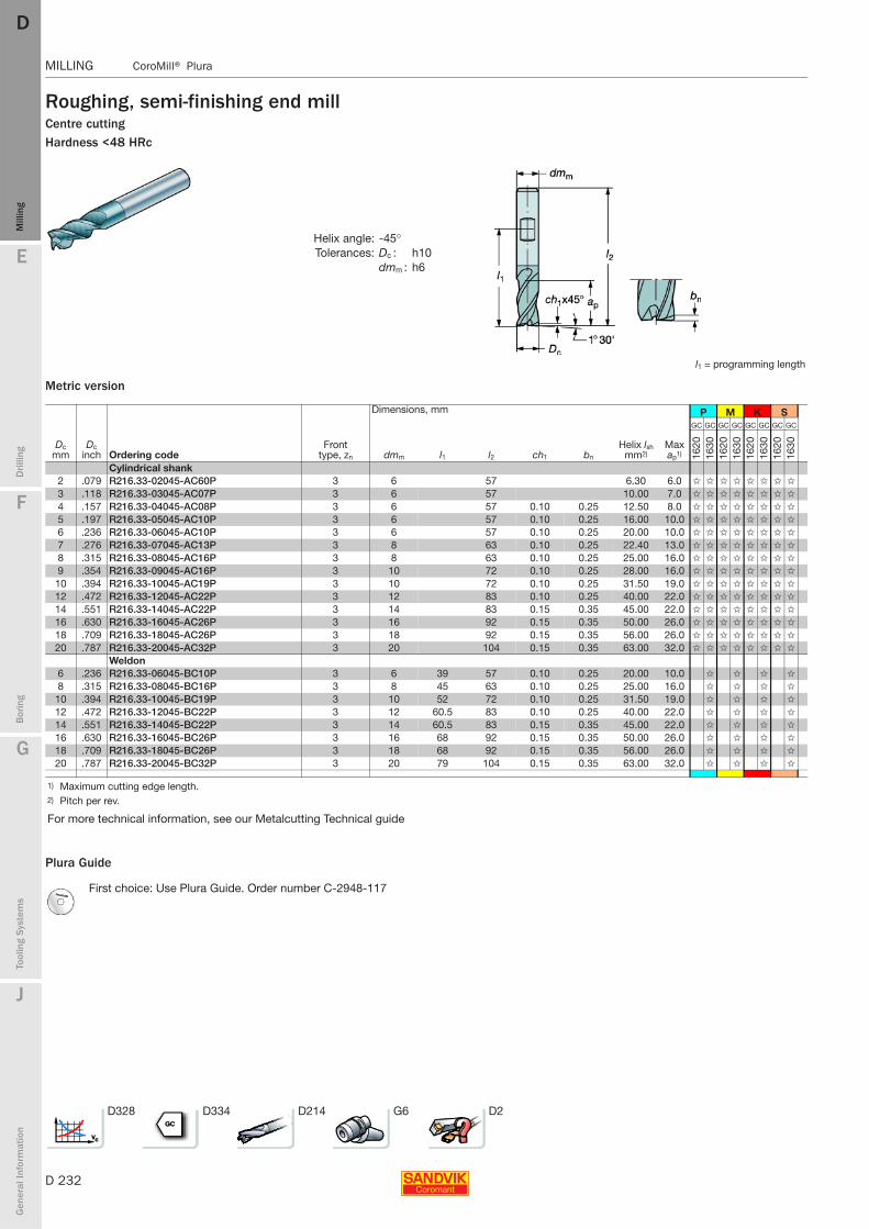
D 232
MILLING CoroMill® Plura
E
Mill
ing
Drilli
ng
F
Bor
ing
G
Tool
ing
Syst
ems
J
Gen
eral
Info
rmat
ion
DDM
illin
g
MILLING CoroMill® Plura
Roughing, semi-finishing end millCentre cuttingHardness <48 HRc
Metric version
Plura Guide
Helix angle: -45°Tolerances: Dc : h10
dmm : h6
l1 = programming length
Dimensions, mm P M K S
Dc mm
Dc inch Ordering code
Front type, zn dmm l1 l2 ch1 bn
Helix lsh mm2)
Max ap1)
GC GC GC GC GC GC GC GC
1620
1630
1620
1630
1620
1630
1620
1630
Cylindrical shank2 .079 R216.33-02045-AC60P 3 6 57 6.30 6.0 ✩ ✩ ✩ ✩ ✩ ✩ ✩ ✩
3 .118 R216.33-03045-AC07P 3 6 57 10.00 7.0 ✩ ✩ ✩ ✩ ✩ ✩ ✩ ✩
4 .157 R216.33-04045-AC08P 3 6 57 0.10 0.25 12.50 8.0 ✩ ✩ ✩ ✩ ✩ ✩ ✩ ✩
5 .197 R216.33-05045-AC10P 3 6 57 0.10 0.25 16.00 10.0 ✩ ✩ ✩ ✩ ✩ ✩ ✩ ✩
6 .236 R216.33-06045-AC10P 3 6 57 0.10 0.25 20.00 10.0 ✩ ✩ ✩ ✩ ✩ ✩ ✩ ✩
7 .276 R216.33-07045-AC13P 3 8 63 0.10 0.25 22.40 13.0 ✩ ✩ ✩ ✩ ✩ ✩ ✩ ✩
8 .315 R216.33-08045-AC16P 3 8 63 0.10 0.25 25.00 16.0 ✩ ✩ ✩ ✩ ✩ ✩ ✩ ✩
9 .354 R216.33-09045-AC16P 3 10 72 0.10 0.25 28.00 16.0 ✩ ✩ ✩ ✩ ✩ ✩ ✩ ✩
10 .394 R216.33-10045-AC19P 3 10 72 0.10 0.25 31.50 19.0 ✩ ✩ ✩ ✩ ✩ ✩ ✩ ✩
12 .472 R216.33-12045-AC22P 3 12 83 0.10 0.25 40.00 22.0 ✩ ✩ ✩ ✩ ✩ ✩ ✩ ✩
14 .551 R216.33-14045-AC22P 3 14 83 0.15 0.35 45.00 22.0 ✩ ✩ ✩ ✩ ✩ ✩ ✩ ✩
16 .630 R216.33-16045-AC26P 3 16 92 0.15 0.35 50.00 26.0 ✩ ✩ ✩ ✩ ✩ ✩ ✩ ✩
18 .709 R216.33-18045-AC26P 3 18 92 0.15 0.35 56.00 26.0 ✩ ✩ ✩ ✩ ✩ ✩ ✩ ✩
20 .787 R216.33-20045-AC32P 3 20 104 0.15 0.35 63.00 32.0 ✩ ✩ ✩ ✩ ✩ ✩ ✩ ✩
Weldon6 .236 R216.33-06045-BC10P 3 6 39 57 0.10 0.25 20.00 10.0 ✩ ✩ ✩ ✩
8 .315 R216.33-08045-BC16P 3 8 45 63 0.10 0.25 25.00 16.0 ✩ ✩ ✩ ✩
10 .394 R216.33-10045-BC19P 3 10 52 72 0.10 0.25 31.50 19.0 ✩ ✩ ✩ ✩
12 .472 R216.33-12045-BC22P 3 12 60.5 83 0.10 0.25 40.00 22.0 ✩ ✩ ✩ ✩
14 .551 R216.33-14045-BC22P 3 14 60.5 83 0.15 0.35 45.00 22.0 ✩ ✩ ✩ ✩
16 .630 R216.33-16045-BC26P 3 16 68 92 0.15 0.35 50.00 26.0 ✩ ✩ ✩ ✩
18 .709 R216.33-18045-BC26P 3 18 68 92 0.15 0.35 56.00 26.0 ✩ ✩ ✩ ✩
20 .787 R216.33-20045-BC32P 3 20 79 104 0.15 0.35 63.00 32.0 ✩ ✩ ✩ ✩
1) Maximum cutting edge length.2) Pitch per rev.
For more technical information, see our Metalcutting Technical guide
First choice: Use Plura Guide. Order number C-2948-117
D328 D334 D214 G6 D2
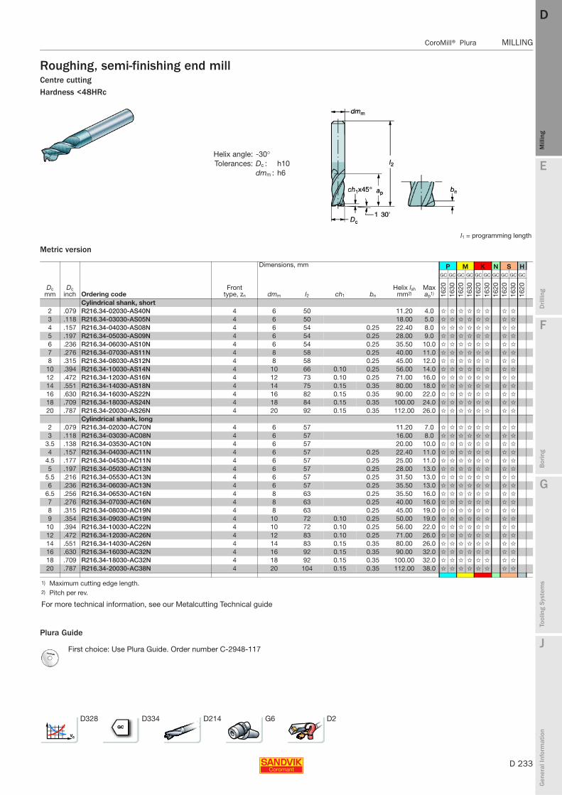
E
D 233
Mill
ing
Drilli
ng
F
Bor
ing
G
Tool
ing
Syst
ems
J
Gen
eral
Info
rmat
ion
DD
Mill
ing
CoroMill® Plura MILLING
MILLING CoroMill® Plura
Roughing, semi-finishing end millCentre cuttingHardness <48HRc
Metric version
Plura Guide
Helix angle: -30°Tolerances: Dc : h10
dmm : h6
l1 = programming length
Dimensions, mm P M K N S H
Dc mm
Dc inch Ordering code
Front type, zn dmm l2 ch1 bn
Helix lsh mm2)
Max ap1)
GC GC GC GC GC GC GC GC GC GC
1620
1630
1620
1630
1620
1630
1620
1620
1630
1620
Cylindrical shank, short2 .079 R216.34-02030-AS40N 4 6 50 11.20 4.0 ✩ ✩ ✩ ✩ ✩ ✩ ✩ ✩
3 .118 R216.34-03030-AS05N 4 6 50 18.00 5.0 ✩ ✩ ✩ ✩ ✩ ✩ ✩ ✩
4 .157 R216.34-04030-AS08N 4 6 54 0.25 22.40 8.0 ✩ ✩ ✩ ✩ ✩ ✩ ✩ ✩
5 .197 R216.34-05030-AS09N 4 6 54 0.25 28.00 9.0 ✩ ✩ ✩ ✩ ✩ ✩ ✩ ✩
6 .236 R216.34-06030-AS10N 4 6 54 0.25 35.50 10.0 ✩ ✩ ✩ ✩ ✩ ✩ ✩ ✩
7 .276 R216.34-07030-AS11N 4 8 58 0.25 40.00 11.0 ✩ ✩ ✩ ✩ ✩ ✩ ✩ ✩
8 .315 R216.34-08030-AS12N 4 8 58 0.25 45.00 12.0 ✩ ✩ ✩ ✩ ✩ ✩ ✩ ✩
10 .394 R216.34-10030-AS14N 4 10 66 0.10 0.25 56.00 14.0 ✩ ✩ ✩ ✩ ✩ ✩ ✩ ✩
12 .472 R216.34-12030-AS16N 4 12 73 0.10 0.25 71.00 16.0 ✩ ✩ ✩ ✩ ✩ ✩ ✩ ✩
14 .551 R216.34-14030-AS18N 4 14 75 0.15 0.35 80.00 18.0 ✩ ✩ ✩ ✩ ✩ ✩ ✩ ✩
16 .630 R216.34-16030-AS22N 4 16 82 0.15 0.35 90.00 22.0 ✩ ✩ ✩ ✩ ✩ ✩ ✩ ✩
18 .709 R216.34-18030-AS24N 4 18 84 0.15 0.35 100.00 24.0 ✩ ✩ ✩ ✩ ✩ ✩ ✩ ✩
20 .787 R216.34-20030-AS26N 4 20 92 0.15 0.35 112.00 26.0 ✩ ✩ ✩ ✩ ✩ ✩ ✩ ✩
Cylindrical shank, long2 .079 R216.34-02030-AC70N 4 6 57 11.20 7.0 ✩ ✩ ✩ ✩ ✩ ✩ ✩ ✩
3 .118 R216.34-03030-AC08N 4 6 57 16.00 8.0 ✩ ✩ ✩ ✩ ✩ ✩ ✩ ✩
3.5 .138 R216.34-03530-AC10N 4 6 57 20.00 10.0 ✩ ✩ ✩ ✩ ✩ ✩ ✩ ✩
4 .157 R216.34-04030-AC11N 4 6 57 0.25 22.40 11.0 ✩ ✩ ✩ ✩ ✩ ✩ ✩ ✩
4.5 .177 R216.34-04530-AC11N 4 6 57 0.25 25.00 11.0 ✩ ✩ ✩ ✩ ✩ ✩ ✩ ✩
5 .197 R216.34-05030-AC13N 4 6 57 0.25 28.00 13.0 ✩ ✩ ✩ ✩ ✩ ✩ ✩ ✩
5.5 .216 R216.34-05530-AC13N 4 6 57 0.25 31.50 13.0 ✩ ✩ ✩ ✩ ✩ ✩ ✩ ✩
6 .236 R216.34-06030-AC13N 4 6 57 0.25 35.50 13.0 ✩ ✩ ✩ ✩ ✩ ✩ ✩ ✩
6.5 .256 R216.34-06530-AC16N 4 8 63 0.25 35.50 16.0 ✩ ✩ ✩ ✩ ✩ ✩ ✩ ✩
7 .276 R216.34-07030-AC16N 4 8 63 0.25 40.00 16.0 ✩ ✩ ✩ ✩ ✩ ✩ ✩ ✩
8 .315 R216.34-08030-AC19N 4 8 63 0.25 45.00 19.0 ✩ ✩ ✩ ✩ ✩ ✩ ✩ ✩
9 .354 R216.34-09030-AC19N 4 10 72 0.10 0.25 50.00 19.0 ✩ ✩ ✩ ✩ ✩ ✩ ✩ ✩
10 .394 R216.34-10030-AC22N 4 10 72 0.10 0.25 56.00 22.0 ✩ ✩ ✩ ✩ ✩ ✩ ✩ ✩
12 .472 R216.34-12030-AC26N 4 12 83 0.10 0.25 71.00 26.0 ✩ ✩ ✩ ✩ ✩ ✩ ✩ ✩
14 .551 R216.34-14030-AC26N 4 14 83 0.15 0.35 80.00 26.0 ✩ ✩ ✩ ✩ ✩ ✩ ✩ ✩
16 .630 R216.34-16030-AC32N 4 16 92 0.15 0.35 90.00 32.0 ✩ ✩ ✩ ✩ ✩ ✩ ✩ ✩
18 .709 R216.34-18030-AC32N 4 18 92 0.15 0.35 100.00 32.0 ✩ ✩ ✩ ✩ ✩ ✩ ✩ ✩
20 .787 R216.34-20030-AC38N 4 20 104 0.15 0.35 112.00 38.0 ✩ ✩ ✩ ✩ ✩ ✩ ✩ ✩
1) Maximum cutting edge length.2) Pitch per rev.
For more technical information, see our Metalcutting Technical guide
First choice: Use Plura Guide. Order number C-2948-117
D328 D334 D214 G6 D2
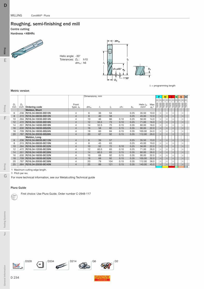
D 234
MILLING CoroMill® Plura
E
Mill
ing
Drilli
ng
F
Bor
ing
G
Tool
ing
Syst
ems
J
Gen
eral
Info
rmat
ion
DDM
illin
g
MILLING CoroMill® Plura
Roughing, semi-finishing end millCentre cuttingHardness <48HRc
Metric version
Plura Guide
Helix angle: -30°Tolerances: Dc : h10
dmm : h6
l1 = programming length
Dimensions, mm P M K N S H
Dc mm
Dc inch Ordering code
Front type, zn dmm l1 l2 ch1 bn
Helix lsh mm2)
Max ap1)
GC GC GC GC GC GC GC GC GC GC
1620
1630
1620
1630
1620
1630
1620
1620
1630
1620
Weldon, Short6 .236 R216.34-06030-BS10N 4 6 36 54 0.25 35.50 10.0 ✩ ✩ ✩ ✩
8 .315 R216.34-08030-BS12N 4 8 40 58 0.25 45.00 12.0 ✩ ✩ ✩ ✩
10 .394 R216.34-10030-BS14N 4 10 46 66 0.10 0.25 56.00 14.0 ✩ ✩ ✩ ✩
12 .472 R216.34-12030-BS16N 4 12 50.5 73 0.10 0.25 71.00 16.0 ✩ ✩ ✩ ✩
14 .551 R216.34-14030-BS18N 4 14 52.5 75 0.15 0.35 80.00 18.0 ✩ ✩ ✩ ✩
16 .630 R216.34-16030-BS22N 4 16 58 82 0.15 0.35 90.00 22.0 ✩ ✩ ✩ ✩
18 .709 R216.34-18030-BS24N 4 18 60 84 0.15 0.35 100.00 24.0 ✩ ✩ ✩ ✩
20 .787 R216.34-20030-BS26N 4 20 67 92 0.15 0.35 112.00 26.0 ✩ ✩ ✩ ✩
Weldon, Long6 .236 R216.34-06030-BC13N 4 6 39 57 0.25 35.50 13.0 ✩ ✩ ✩ ✩
8 .315 R216.34-08030-BC19N 4 8 45 63 0.25 45.00 19.0 ✩ ✩ ✩ ✩
10 .394 R216.34-10030-BC22N 4 10 52 72 0.10 0.25 56.00 22.0 ✩ ✩ ✩ ✩
12 .472 R216.34-12030-BC26N 4 12 60.5 83 0.10 0.25 71.00 26.0 ✩ ✩ ✩ ✩
14 .551 R216.34-14030-BC26N 4 14 60.5 83 0.15 0.35 80.00 26.0 ✩ ✩ ✩ ✩
16 .630 R216.34-16030-BC32N 4 16 68 92 0.15 0.35 90.00 32.0 ✩ ✩ ✩ ✩
18 .709 R216.34-18030-BC32N 4 18 68 92 0.15 0.35 100.00 32.0 ✩ ✩ ✩ ✩
20 .787 R216.34-20030-BC38N 4 20 79 104 0.15 0.35 112.00 38.0 ✩ ✩ ✩ ✩
25 .984 R216.34-25030-BC45N 4 25 89 121 0.15 0.35 140.00 45.0 ✩ ✩ ✩ ✩
1) Maximum cutting edge length.2) Pitch per rev.
For more technical information, see our Metalcutting Technical guide
First choice: Use Plura Guide. Order number C-2948-117
D328 D334 D214 G6 D2
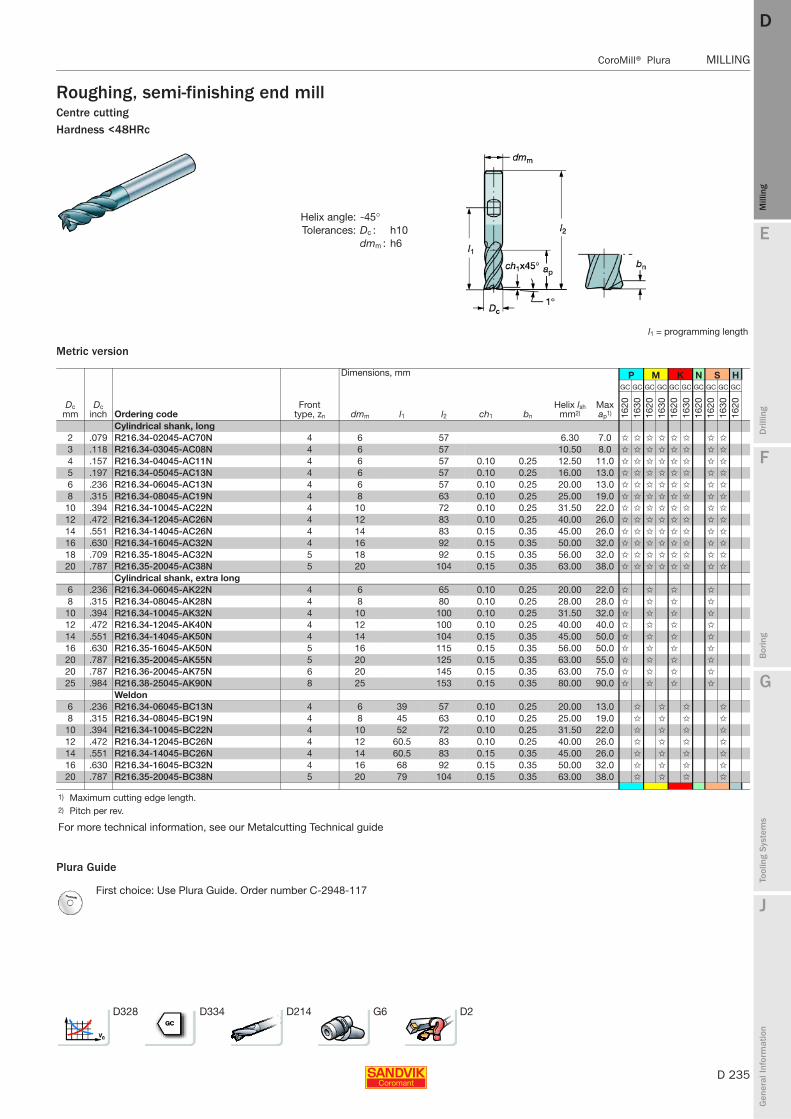
E
D 235
Mill
ing
Drilli
ng
F
Bor
ing
G
Tool
ing
Syst
ems
J
Gen
eral
Info
rmat
ion
DD
Mill
ing
CoroMill® Plura MILLING
MILLING CoroMill® Plura
Roughing, semi-finishing end millCentre cuttingHardness <48HRc
Metric version
Plura Guide
Helix angle: -45°Tolerances: Dc : h10
dmm : h6
l1 = programming length
Dimensions, mm P M K N S H
Dc mm
Dc inch Ordering code
Front type, zn dmm l1 l2 ch1 bn
Helix lsh mm2)
Max ap1)
GC GC GC GC GC GC GC GC GC GC
1620
1630
1620
1630
1620
1630
1620
1620
1630
1620
Cylindrical shank, long2 .079 R216.34-02045-AC70N 4 6 57 6.30 7.0 ✩ ✩ ✩ ✩ ✩ ✩ ✩ ✩
3 .118 R216.34-03045-AC08N 4 6 57 10.50 8.0 ✩ ✩ ✩ ✩ ✩ ✩ ✩ ✩
4 .157 R216.34-04045-AC11N 4 6 57 0.10 0.25 12.50 11.0 ✩ ✩ ✩ ✩ ✩ ✩ ✩ ✩
5 .197 R216.34-05045-AC13N 4 6 57 0.10 0.25 16.00 13.0 ✩ ✩ ✩ ✩ ✩ ✩ ✩ ✩
6 .236 R216.34-06045-AC13N 4 6 57 0.10 0.25 20.00 13.0 ✩ ✩ ✩ ✩ ✩ ✩ ✩ ✩
8 .315 R216.34-08045-AC19N 4 8 63 0.10 0.25 25.00 19.0 ✩ ✩ ✩ ✩ ✩ ✩ ✩ ✩
10 .394 R216.34-10045-AC22N 4 10 72 0.10 0.25 31.50 22.0 ✩ ✩ ✩ ✩ ✩ ✩ ✩ ✩
12 .472 R216.34-12045-AC26N 4 12 83 0.10 0.25 40.00 26.0 ✩ ✩ ✩ ✩ ✩ ✩ ✩ ✩
14 .551 R216.34-14045-AC26N 4 14 83 0.15 0.35 45.00 26.0 ✩ ✩ ✩ ✩ ✩ ✩ ✩ ✩
16 .630 R216.34-16045-AC32N 4 16 92 0.15 0.35 50.00 32.0 ✩ ✩ ✩ ✩ ✩ ✩ ✩ ✩
18 .709 R216.35-18045-AC32N 5 18 92 0.15 0.35 56.00 32.0 ✩ ✩ ✩ ✩ ✩ ✩ ✩ ✩
20 .787 R216.35-20045-AC38N 5 20 104 0.15 0.35 63.00 38.0 ✩ ✩ ✩ ✩ ✩ ✩ ✩ ✩
Cylindrical shank, extra long6 .236 R216.34-06045-AK22N 4 6 65 0.10 0.25 20.00 22.0 ✩ ✩ ✩ ✩
8 .315 R216.34-08045-AK28N 4 8 80 0.10 0.25 28.00 28.0 ✩ ✩ ✩ ✩
10 .394 R216.34-10045-AK32N 4 10 100 0.10 0.25 31.50 32.0 ✩ ✩ ✩ ✩
12 .472 R216.34-12045-AK40N 4 12 100 0.10 0.25 40.00 40.0 ✩ ✩ ✩ ✩
14 .551 R216.34-14045-AK50N 4 14 104 0.15 0.35 45.00 50.0 ✩ ✩ ✩ ✩
16 .630 R216.35-16045-AK50N 5 16 115 0.15 0.35 56.00 50.0 ✩ ✩ ✩ ✩
20 .787 R216.35-20045-AK55N 5 20 125 0.15 0.35 63.00 55.0 ✩ ✩ ✩ ✩
20 .787 R216.36-20045-AK75N 6 20 145 0.15 0.35 63.00 75.0 ✩ ✩ ✩ ✩
25 .984 R216.38-25045-AK90N 8 25 153 0.15 0.35 80.00 90.0 ✩ ✩ ✩ ✩
Weldon6 .236 R216.34-06045-BC13N 4 6 39 57 0.10 0.25 20.00 13.0 ✩ ✩ ✩ ✩
8 .315 R216.34-08045-BC19N 4 8 45 63 0.10 0.25 25.00 19.0 ✩ ✩ ✩ ✩
10 .394 R216.34-10045-BC22N 4 10 52 72 0.10 0.25 31.50 22.0 ✩ ✩ ✩ ✩
12 .472 R216.34-12045-BC26N 4 12 60.5 83 0.10 0.25 40.00 26.0 ✩ ✩ ✩ ✩
14 .551 R216.34-14045-BC26N 4 14 60.5 83 0.15 0.35 45.00 26.0 ✩ ✩ ✩ ✩
16 .630 R216.34-16045-BC32N 4 16 68 92 0.15 0.35 50.00 32.0 ✩ ✩ ✩ ✩
20 .787 R216.35-20045-BC38N 5 20 79 104 0.15 0.35 63.00 38.0 ✩ ✩ ✩ ✩
1) Maximum cutting edge length.2) Pitch per rev.
For more technical information, see our Metalcutting Technical guide
First choice: Use Plura Guide. Order number C-2948-117
D328 D334 D214 G6 D2

D 236
MILLING CoroMill® Plura
E
Mill
ing
Drilli
ng
F
Bor
ing
G
Tool
ing
Syst
ems
J
Gen
eral
Info
rmat
ion
DDM
illin
g
MILLING CoroMill® Plura
Roughing, semi-finishing end mill
Centre cutting
Metric version
Plura Guide
Helix angle: -30° , Tolerances: Dc : h10
dmm : h6
This cutter has a new design improving drilling capability.
Dimensions, mm N
Dc mm
Dc inch Ordering code
Front type, zn dmm l2 l3 d4
Helix lsh mm2) ch1 αo
Max ap1)
-
H10
F
Cylindrical shank2 .079 R216.32-02030-AC60A 2 6 57 9.5 11.20 13 6.0 ✩
3 .118 R216.32-03030-AC07A 2 6 57 10.4 18.00 13 7.0 ✩
4 .157 R216.32-04030-AC08A 2 6 57 15.3 22.40 13 8.0 ✩
5 .197 R216.32-05030-AC10A 2 6 57 16.1 28.00 13 10.0 ✩
6 .236 R216.32-06030-AC10A 2 6 57 35.50 13 10.0 ✩
8 .315 R216.32-08030-AC16A 2 8 63 45.00 13 16.0 ✩
10 .394 R216.32-10030-AC19A 2 10 72 56.00 0.1 13 19.0 ✩
12 .472 R216.32-12030-AC22A 2 12 83 71.00 0.1 13 22.0 ✩
2 .079 R216.32-02025-AK80A 2 6 57 10 14.00 20 8.0 ✩
3 .118 R216.32-03025-AK12A 2 6 57 15 22.40 20 12.0 ✩
4 .157 R216.32-04025-AK14A 2 6 57 18 28.00 14 14.0 ✩
5 .197 R216.32-05025-AK16A 2 6 57 35.50 14 16.0 ✩
6 .236 R216.32-06025-AK22A 2 6 65 45.00 14 22.0 ✩
8 .315 R216.32-08025-AK28A 2 8 80 56.00 14 28.0 ✩
10 .394 R216.32-10025-AK32A 2 10 90 71.00 0.1 12 32.0 ✩
12 .472 R216.32-12025-AK38A 2 12 100 90.00 0.1 12 38.0 ✩
2 .079 R216.32-02025-AP30A 2 3 57 6 1.9 14.00 20 3.0 ✩
3 .118 R216.32-03025-AP04A 2 3 57 7 2.9 22.40 20 4.0 ✩
4 .157 R216.32-04025-AP06A 2 4 57 10 3.8 28.00 14 6.0 ✩
5 .197 R216.32-05025-AP08A 2 6 57 16 4.8 35.50 14 8.0 ✩
6 .236 R216.32-06025-AP10A 2 6 65 28 5.7 45.00 14 10.0 ✩
8 .315 R216.32-08025-AP12A 2 8 80 35 7.7 56.00 14 12.0 ✩
10 .394 R216.32-10025-AP14A 2 10 90 45 9.7 71.00 0.1 12 14.0 ✩
12 .472 R216.32-12025-AP16A 2 12 100 50 11.7 90.00 0.1 12 16.0 ✩
16 .630 R216.32-16025-AP20A 2 16 115 63 15.5 112.00 0.15 12 20.0 ✩
20 .787 R216.32-20025-AP20A 2 20 125 70 19.5 140.00 0.15 10 20.0 ✩
1) Maximum cutting edge length.2) Pitch per rev.
For more technical information, see our Metalcutting Technical guide
First choice: Use Plura Guide. Order number C-2948-117
D328 D334 D214 G6 D2
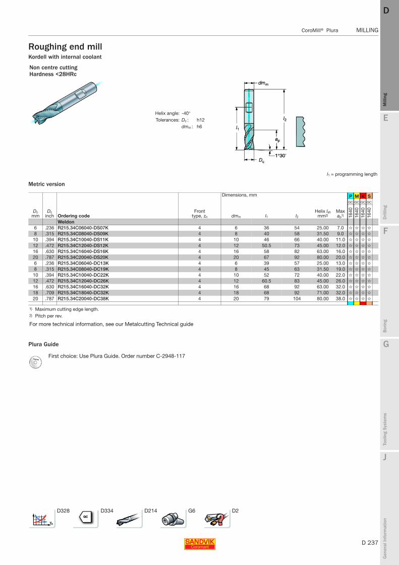
E
D 237
Mill
ing
Drilli
ng
F
Bor
ing
G
Tool
ing
Syst
ems
J
Gen
eral
Info
rmat
ion
DD
Mill
ing
CoroMill® Plura MILLING
MILLING CoroMill® Plura
Roughing end millKordell with internal coolant
Metric version
Plura Guide
Non centre cuttingHardness <28HRc
Helix angle: -40°Tolerances: Dc : h12
dmm : h6
l1 = programming length
Dimensions, mm P M K S
Dc mm
Dc inch Ordering code
Front type, zn dmm l1 l2
Helix lsh mm2)
Max ap1)
GC GC GC GC
1640
1640
1640
1640
Weldon6 .236 R215.34C06040-DS07K 4 6 36 54 25.00 7.0 ✩ ✩ ✩ ✩
8 .315 R215.34C08040-DS09K 4 8 40 58 31.50 9.0 ✩ ✩ ✩ ✩
10 .394 R215.34C10040-DS11K 4 10 46 66 40.00 11.0 ✩ ✩ ✩ ✩
12 .472 R215.34C12040-DS12K 4 12 50.5 73 45.00 12.0 ✩ ✩ ✩ ✩
16 .630 R215.34C16040-DS16K 4 16 58 82 63.00 16.0 ✩ ✩ ✩ ✩
20 .787 R215.34C20040-DS20K 4 20 67 92 80.00 20.0 ✩ ✩ ✩ ✩
6 .236 R215.34C06040-DC13K 4 6 39 57 25.00 13.0 ✩ ✩ ✩ ✩
8 .315 R215.34C08040-DC19K 4 8 45 63 31.50 19.0 ✩ ✩ ✩ ✩
10 .394 R215.34C10040-DC22K 4 10 52 72 40.00 22.0 ✩ ✩ ✩ ✩
12 .472 R215.34C12040-DC26K 4 12 60.5 83 45.00 26.0 ✩ ✩ ✩ ✩
16 .630 R215.34C16040-DC32K 4 16 68 92 63.00 32.0 ✩ ✩ ✩ ✩
18 .709 R215.34C18040-DC32K 4 18 68 92 71.00 32.0 ✩ ✩ ✩ ✩
20 .787 R215.34C20040-DC38K 4 20 79 104 80.00 38.0 ✩ ✩ ✩ ✩
1) Maximum cutting edge length.2) Pitch per rev.
For more technical information, see our Metalcutting Technical guide
First choice: Use Plura Guide. Order number C-2948-117
D328 D334 D214 G6 D2

D 238
MILLING CoroMill® Plura
E
Mill
ing
Drilli
ng
F
Bor
ing
G
Tool
ing
Syst
ems
J
Gen
eral
Info
rmat
ion
DDM
illin
g
MILLING CoroMill® Plura
Roughing end millCentre cuttingKordell
Metric version
Plura Guide
Hardness <28HRc
Helix angle: -30° ,-40°Tolerances: Dc : h12
dmm : h6
l1 = programming length
Dimensions, mm P M K
Dc mm
Dc inch Ordering code
Front type, zn dmm l1 l2
Helix lsh mm2)
Max ap1)
GC GC GC
1640
1640
1640
Weldon, Short6 .236 R216.33-06030-BS07K 3 6 36 54 35.50 7.0 ✩ ✩ ✩
8 .315 R216.33-08030-BS09K 3 6 40 58 45.00 9.0 ✩ ✩ ✩
10 .394 R216.33-10030-BS11K 3 10 46 66 56.00 11.0 ✩ ✩ ✩
12 .472 R216.33-12030-BS12K 3 12 50.5 73 71.00 12.0 ✩ ✩ ✩
14 .551 R216.33-14030-BS14K 3 14 52.5 75 80.00 14.0 ✩ ✩ ✩
16 .630 R216.33-16030-BS16K 3 16 58 82 90.00 16.0 ✩ ✩ ✩
20 .787 R216.33-20030-BS20K 3 20 67 92 112.00 20.0 ✩ ✩ ✩
Weldon, Long6 .236 R216.34-06040-BC13K 4 6 39 57 25.00 13.0 ✩ ✩ ✩
8 .315 R216.34-08040-BC19K 4 8 45 63 31.50 19.0 ✩ ✩ ✩
10 .394 R216.34-10040-BC22K 4 10 52 72 40.00 22.0 ✩ ✩ ✩
12 .472 R216.34-12040-BC26K 4 12 60.5 83 45.00 26.0 ✩ ✩ ✩
14 .551 R216.34-14040-BC26K 4 14 60.5 83 56.00 26.0 ✩ ✩ ✩
16 .630 R216.34-16040-BC32K 4 16 68 92 63.00 32.0 ✩ ✩ ✩
18 .709 R216.34-18040-BC32K 4 18 68 92 71.00 32.0 ✩ ✩ ✩
20 .787 R216.34-20040-BC38K 4 20 79 104 80.00 38.0 ✩ ✩ ✩
1) Maximum cutting edge length.2) Pitch per rev.
For more technical information, see our Metalcutting Technical guide
First choice: Use Plura Guide. Order number C-2948-117
D328 D334 D214 G6 D2
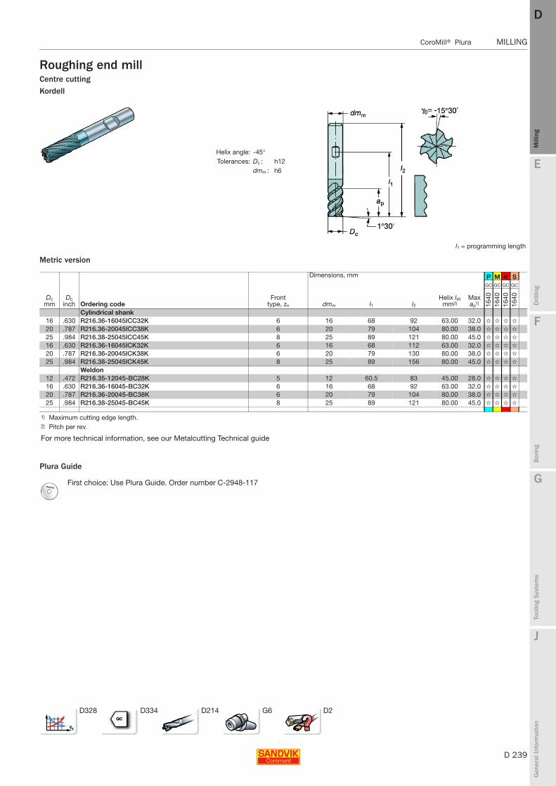
E
D 239
Mill
ing
Drilli
ng
F
Bor
ing
G
Tool
ing
Syst
ems
J
Gen
eral
Info
rmat
ion
DD
Mill
ing
CoroMill® Plura MILLING
MILLING CoroMill® Plura
Roughing end millCentre cuttingKordell
Metric version
Plura Guide
Helix angle: -45°Tolerances: Dc : h12
dmm : h6
l1 = programming length
Dimensions, mm P M K S
Dc mm
Dc inch Ordering code
Front type, zn dmm l1 l2
Helix lsh mm2)
Max ap1)
GC GC GC GC
1640
1640
1640
1640
Cylindrical shank16 .630 R216.36-16045ICC32K 6 16 68 92 63.00 32.0 ✩ ✩ ✩ ✩
20 .787 R216.36-20045ICC38K 6 20 79 104 80.00 38.0 ✩ ✩ ✩ ✩
25 .984 R216.38-25045ICC45K 8 25 89 121 80.00 45.0 ✩ ✩ ✩ ✩
16 .630 R216.36-16045ICK32K 6 16 68 112 63.00 32.0 ✩ ✩ ✩ ✩
20 .787 R216.36-20045ICK38K 6 20 79 130 80.00 38.0 ✩ ✩ ✩ ✩
25 .984 R216.38-25045ICK45K 8 25 89 156 80.00 45.0 ✩ ✩ ✩ ✩
Weldon12 .472 R216.35-12045-BC28K 5 12 60.5 83 45.00 28.0 ✩ ✩ ✩ ✩
16 .630 R216.36-16045-BC32K 6 16 68 92 63.00 32.0 ✩ ✩ ✩ ✩
20 .787 R216.36-20045-BC38K 6 20 79 104 80.00 38.0 ✩ ✩ ✩ ✩
25 .984 R216.38-25045-BC45K 8 25 89 121 80.00 45.0 ✩ ✩ ✩ ✩
1) Maximum cutting edge length.2) Pitch per rev.
For more technical information, see our Metalcutting Technical guide
First choice: Use Plura Guide. Order number C-2948-117
D328 D334 D214 G6 D2

D 240
MILLING CoroMill® Plura
E
Mill
ing
Drilli
ng
F
Bor
ing
G
Tool
ing
Syst
ems
J
Gen
eral
Info
rmat
ion
DDM
illin
g
MILLING CoroMill® Plura
Roughing end millCentre cuttingChip dividing
Metric version
Plura Guide
KordellHardness <48HRc
Helix angle: -30°Tolerances: Dc : h10
dmm : h6
l1 = programming length
Dimensions, mm S
Dc mm
Dc inch Ordering code
Front type, zn dmm l1 l2 ch1 bn
Helix lsh mm2)
Max ap1)
GC
1620
Weldon6 .236 R216.34-06030-BC13B 4 6 39 57 0.25 35.50 13.0 ✩
8 .315 R216.34-08030-BC19B 4 8 45 63 0.25 45.00 19.0 ✩
10 .394 R216.34-10030-BC22B 4 10 52 72 0.10 0.25 56.00 22.0 ✩
12 .472 R216.34-12030-BC26B 4 12 60.5 83 0.10 0.25 71.00 26.0 ✩
14 .551 R216.34-14030-BC26B 4 14 60.5 83 0.15 0.35 80.00 26.0 ✩
16 .630 R216.34-16030-BC32B 4 16 68 92 0.15 0.35 90.00 32.0 ✩
18 .709 R216.34-18030-BC32B 4 18 68 92 0.15 0.35 100.00 32.0 ✩
20 .787 R216.34-20030-BC38B 4 20 79 104 0.15 0.35 112.00 38.0 ✩
25 .984 R216.35-25030-BC45B 5 25 93 125 0.15 0.35 140.00 45.0 ✩
1) Maximum cutting edge length.2) Pitch per rev.
For more technical information, see our Metalcutting Technical guide
First choice: Use Plura Guide. Order number C-2948-117
D328 D334 D214 G6 D2
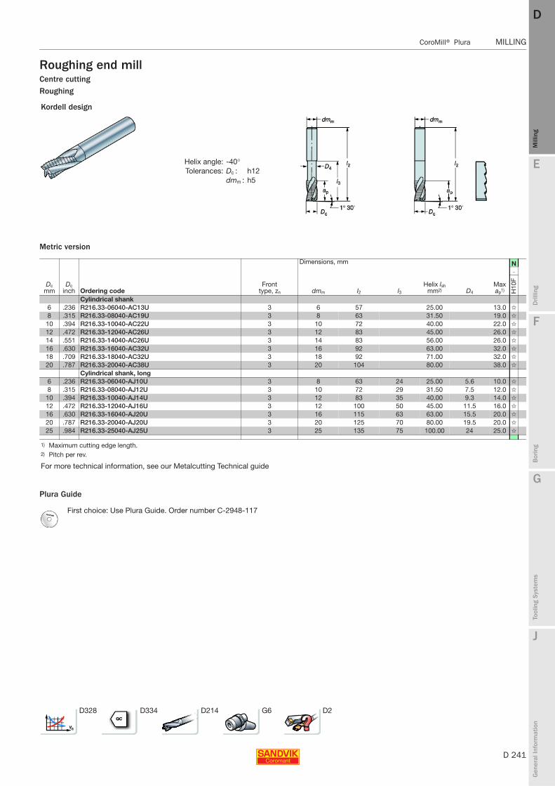
E
D 241
Mill
ing
Drilli
ng
F
Bor
ing
G
Tool
ing
Syst
ems
J
Gen
eral
Info
rmat
ion
DD
Mill
ing
CoroMill® Plura MILLING
MILLING CoroMill® Plura
Roughing end millCentre cuttingRoughing
Metric version
Plura Guide
Kordell design
Helix angle: -40°Tolerances: Dc : h12
dmm : h5
Dimensions, mm N
Dc mm
Dc inch Ordering code
Front type, zn dmm l2 l3
Helix lsh mm2) D4
Max ap1)
-
H10
F
Cylindrical shank6 .236 R216.33-06040-AC13U 3 6 57 25.00 13.0 ✩
8 .315 R216.33-08040-AC19U 3 8 63 31.50 19.0 ✩
10 .394 R216.33-10040-AC22U 3 10 72 40.00 22.0 ✩
12 .472 R216.33-12040-AC26U 3 12 83 45.00 26.0 ✩
14 .551 R216.33-14040-AC26U 3 14 83 56.00 26.0 ✩
16 .630 R216.33-16040-AC32U 3 16 92 63.00 32.0 ✩
18 .709 R216.33-18040-AC32U 3 18 92 71.00 32.0 ✩
20 .787 R216.33-20040-AC38U 3 20 104 80.00 38.0 ✩
Cylindrical shank, long6 .236 R216.33-06040-AJ10U 3 8 63 24 25.00 5.6 10.0 ✩
8 .315 R216.33-08040-AJ12U 3 10 72 29 31.50 7.5 12.0 ✩
10 .394 R216.33-10040-AJ14U 3 12 83 35 40.00 9.3 14.0 ✩
12 .472 R216.33-12040-AJ16U 3 12 100 50 45.00 11.5 16.0 ✩
16 .630 R216.33-16040-AJ20U 3 16 115 63 63.00 15.5 20.0 ✩
20 .787 R216.33-20040-AJ20U 3 20 125 70 80.00 19.5 20.0 ✩
25 .984 R216.33-25040-AJ25U 3 25 135 75 100.00 24 25.0 ✩
1) Maximum cutting edge length.2) Pitch per rev.
For more technical information, see our Metalcutting Technical guide
First choice: Use Plura Guide. Order number C-2948-117
D328 D334 D214 G6 D2
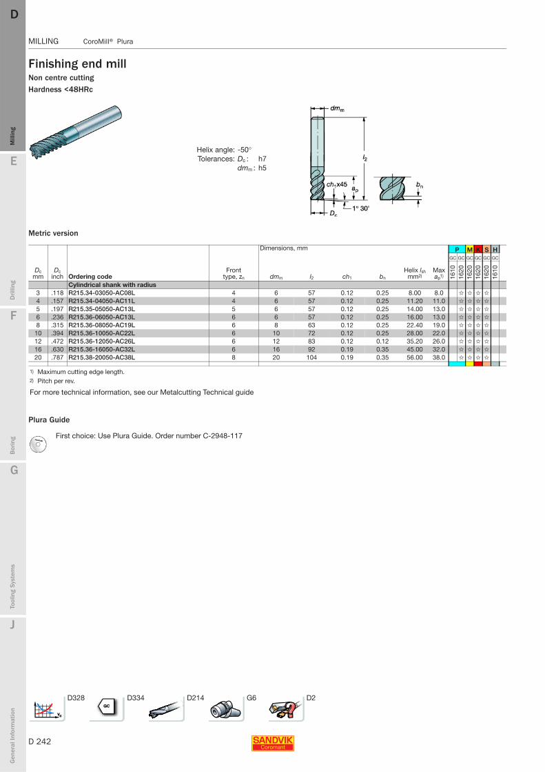
D 242
MILLING CoroMill® Plura
E
Mill
ing
Drilli
ng
F
Bor
ing
G
Tool
ing
Syst
ems
J
Gen
eral
Info
rmat
ion
DDM
illin
g
MILLING CoroMill® Plura
Finishing end millNon centre cuttingHardness <48HRc
Metric version
Plura Guide
Helix angle: -50°Tolerances: Dc : h7
dmm : h5
Dimensions, mm P M K S H
Dc mm
Dc inch Ordering code
Front type, zn dmm l2 ch1 bn
Helix lsh mm2)
Max ap1)
GC GC GC GC GC GC
1610
1620
1620
1620
1620
1610
Cylindrical shank with radius3 .118 R215.34-03050-AC08L 4 6 57 0.12 0.25 8.00 8.0 ✩ ✩ ✩ ✩
4 .157 R215.34-04050-AC11L 4 6 57 0.12 0.25 11.20 11.0 ✩ ✩ ✩ ✩
5 .197 R215.35-05050-AC13L 5 6 57 0.12 0.25 14.00 13.0 ✩ ✩ ✩ ✩
6 .236 R215.36-06050-AC13L 6 6 57 0.12 0.25 16.00 13.0 ✩ ✩ ✩ ✩
8 .315 R215.36-08050-AC19L 6 8 63 0.12 0.25 22.40 19.0 ✩ ✩ ✩ ✩
10 .394 R215.36-10050-AC22L 6 10 72 0.12 0.25 28.00 22.0 ✩ ✩ ✩ ✩
12 .472 R215.36-12050-AC26L 6 12 83 0.12 0.12 35.20 26.0 ✩ ✩ ✩ ✩
16 .630 R215.36-16050-AC32L 6 16 92 0.19 0.35 45.00 32.0 ✩ ✩ ✩ ✩
20 .787 R215.38-20050-AC38L 8 20 104 0.19 0.35 56.00 38.0 ✩ ✩ ✩ ✩
1) Maximum cutting edge length.2) Pitch per rev.
For more technical information, see our Metalcutting Technical guide
First choice: Use Plura Guide. Order number C-2948-117
D328 D334 D214 G6 D2

E
D 243
Mill
ing
Drilli
ng
F
Bor
ing
G
Tool
ing
Syst
ems
J
Gen
eral
Info
rmat
ion
DD
Mill
ing
CoroMill® Plura MILLING
MILLING CoroMill® Plura
Finishing end millNon centre cuttingHardness <48HRc
Metric version
Plura Guide
Helix angle: -60°Tolerances: Dc : h10
dmm : h6
Dimensions, mm P M K S H
Dc mm
Dc inch Ordering code
Front type, zn dmm l2 ch1 bn
Helix lsh mm2)
Max ap1)
GC GC GC GC GC GC
1610
1620
1620
1620
1620
1610
Cylindrical shank6 .236 R215.36-06060-AC13L 6 6 57 0.10 0.25 11.20 13.0 ✩ ✩ ✩ ✩
8 .315 R215.36-08060-AC19L 6 8 63 0.10 0.25 16.00 19.0 ✩ ✩ ✩ ✩
10 .394 R215.36-10060-AC22L 6 10 72 0.10 0.25 20.00 22.0 ✩ ✩ ✩ ✩
12 .472 R215.36-12060-AC26L 6 12 83 0.10 0.25 22.40 26.0 ✩ ✩ ✩ ✩
14 .551 R215.36-14060-AC26L 6 14 83 0.15 0.35 28.00 26.0 ✩ ✩ ✩ ✩
16 .630 R215.36-16060-AC32L 6 16 92 0.15 0.35 31.50 32.0 ✩ ✩ ✩ ✩
18 .709 R215.36-18060-AC32L 6 18 92 0.15 0.35 35.50 32.0 ✩ ✩ ✩ ✩
20 .787 R215.36-20060-AC38L 6 20 104 0.15 0.35 40.00 38.0 ✩ ✩ ✩ ✩
1) Maximum cutting edge length.2) Pitch per rev.
For more technical information, see our Metalcutting Technical guide
First choice: Use Plura Guide. Order number C-2948-117
D328 D334 D214 G6 D2

D 244
MILLING CoroMill® Plura
E
Mill
ing
Drilli
ng
F
Bor
ing
G
Tool
ing
Syst
ems
J
Gen
eral
Info
rmat
ion
DDM
illin
g
MILLING CoroMill® Plura
Finishing end millNon centre cuttingHardness <48HRc
Inch version
Plura Guide
Helix angle: -50°Tolerances: Dc : h10
dmm : h6
Dimensions, inch P M K S H
Dc mm
Dc inch Ordering code
Front type, zn dmm l2 l3 rε Helix lsh2)
Max ap1)
GC GC GC GC GC GC
1610
1620
1620
1620
1620
1610
Cylindrical shank with radius1.57 .062 RA215.24-0450AAK13L 4 .250 3.000 .250 .015 .007 .200 ✩ ✩ ✩ ✩
2.36 .093 RA215.24-0650AAK18L 4 .250 3.000 .375 .015 .010 .286 ✩ ✩ ✩ ✩
2.36 .093 RA215.24-0650BAK18L 4 .250 3.000 .375 .031 .010 .286 ✩ ✩ ✩ ✩
3.18 .125 RA215.24-0850AAK06L 4 .250 3.000 .500 .015 .014 .375 ✩ ✩ ✩ ✩
3.18 .125 RA215.24-0850BAK06L 4 .250 3.000 .500 .031 .014 .375 ✩ ✩ ✩ ✩
3.96 .156 RA215.24-1050AAK08L 4 .250 3.000 .625 .015 .017 .500 ✩ ✩ ✩ ✩
3.96 .156 RA215.24-1050BAK08L 4 .250 3.000 .625 .031 .017 .500 ✩ ✩ ✩ ✩
4.75 .187 RA215.26-1250AAK09L 6 .250 3.000 .750 .015 .022 .571 ✩ ✩ ✩ ✩
4.75 .187 RA215.26-1250BAK09L 6 .250 3.000 .750 .031 .022 .571 ✩ ✩ ✩ ✩
6.35 .250 RA215.26-1650AAK12L 6 .250 3.000 .015 .028 .750 ✩ ✩ ✩ ✩
6.35 .250 RA215.26-1650BAK12L 6 .250 3.000 .031 .028 .750 ✩ ✩ ✩ ✩
6.35 .250 RA215.26-1650BAL18L 6 .250 4.000 .031 .028 1.125 ✩ ✩ ✩ ✩
7.92 .312 RA215.26-2050AAK15L 6 .375 3.500 1.250 .015 .035 1.000 ✩ ✩ ✩ ✩
7.92 .312 RA215.26-2050BAK15L 6 .375 3.500 1.250 .031 .035 1.000 ✩ ✩ ✩ ✩
7.92 .312 RA215.26-2050BAL23L 6 .375 4.500 1.750 .031 .035 1.400 ✩ ✩ ✩ ✩
9.52 .375 RA215.26-2450BAK18L 6 .375 3.500 .031 .043 1.125 ✩ ✩ ✩ ✩
9.52 .375 RA215.26-2450DAK18L 6 .375 3.500 .062 .043 1.125 ✩ ✩ ✩ ✩
9.52 .375 RA215.26-2450DAL27L 6 .375 4.500 .062 .043 1.666 ✩ ✩ ✩ ✩
12.70 .500 RA215.26-3250BAK24L 6 .500 4.000 .031 .055 1.500 ✩ ✩ ✩ ✩
12.70 .500 RA215.26-3250DAK24L 6 .500 4.000 .062 .055 1.500 ✩ ✩ ✩ ✩
12.70 .500 RA215.26-3250DAL36L 6 .500 5.000 .062 .055 2.250 ✩ ✩ ✩ ✩
15.88 .625 RA215.26-4050DAK30L 6 .625 4.500 .062 .070 1.875 ✩ ✩ ✩ ✩
15.88 .625 RA215.26-4050HAK30L 6 .625 4.500 .125 .070 1.875 ✩ ✩ ✩ ✩
15.88 .625 RA215.26-4050HAL45L 6 .625 5.500 .125 .070 2.800 ✩ ✩ ✩ ✩
19.05 .750 RA215.28-4850DAK36L 8 .750 5.000 .062 .087 2.250 ✩ ✩ ✩ ✩
19.05 .750 RA215.28-4850HAK36L 8 .750 5.000 .125 .087 2.250 ✩ ✩ ✩ ✩
19.05 .750 RA215.28-4850HAL54L 8 .750 6.000 .125 .087 3.375 ✩ ✩ ✩ ✩
1) Maximum cutting edge length.2) Pitch per rev.
For more technical information, see our Metalcutting Technical guide
First choice: Use Plura Guide. Order number C-2948-117
D328 D334 D214 G6 D2
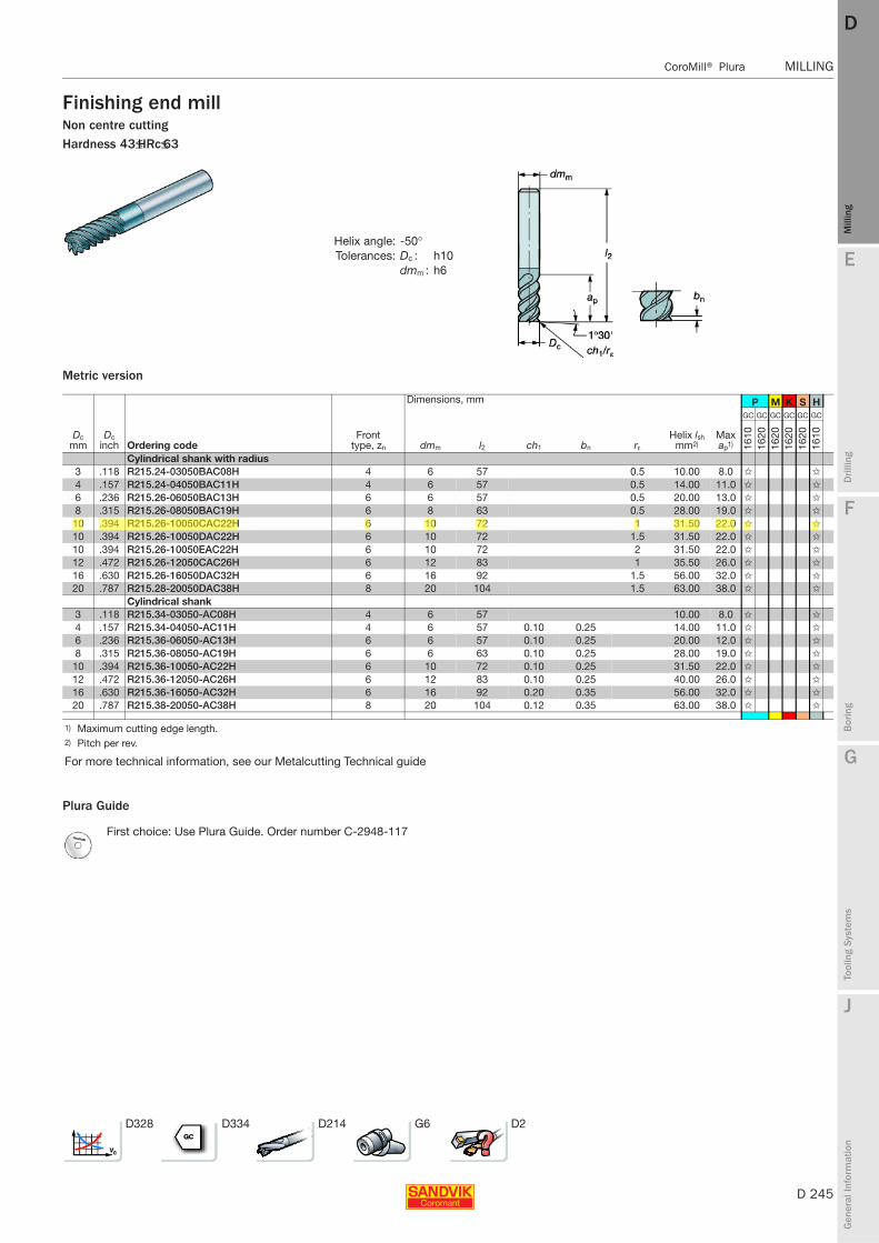
E
D 245
Mill
ing
Drilli
ng
F
Bor
ing
G
Tool
ing
Syst
ems
J
Gen
eral
Info
rmat
ion
DD
Mill
ing
CoroMill® Plura MILLING
MILLING CoroMill® Plura
Finishing end millNon centre cuttingHardness 43≤HRc≤63
Metric version
Plura Guide
Helix angle: -50°Tolerances: Dc : h10
dmm : h6
Dimensions, mm P M K S H
Dc mm
Dc inch Ordering code
Front type, zn dmm l2 ch1 bn rε
Helix lsh mm2)
Max ap1)
GC GC GC GC GC GC
1610
1620
1620
1620
1620
1610
Cylindrical shank with radius3 .118 R215.24-03050BAC08H 4 6 57 0.5 10.00 8.0 ✩ ✩
4 .157 R215.24-04050BAC11H 4 6 57 0.5 14.00 11.0 ✩ ✩
6 .236 R215.26-06050BAC13H 6 6 57 0.5 20.00 13.0 ✩ ✩
8 .315 R215.26-08050BAC19H 6 8 63 0.5 28.00 19.0 ✩ ✩
10 .394 R215.26-10050CAC22H 6 10 72 1 31.50 22.0 ✩ ✩
10 .394 R215.26-10050DAC22H 6 10 72 1.5 31.50 22.0 ✩ ✩
10 .394 R215.26-10050EAC22H 6 10 72 2 31.50 22.0 ✩ ✩
12 .472 R215.26-12050CAC26H 6 12 83 1 35.50 26.0 ✩ ✩
16 .630 R215.26-16050DAC32H 6 16 92 1.5 56.00 32.0 ✩ ✩
20 .787 R215.28-20050DAC38H 8 20 104 1.5 63.00 38.0 ✩ ✩
Cylindrical shank3 .118 R215.34-03050-AC08H 4 6 57 10.00 8.0 ✩ ✩
4 .157 R215.34-04050-AC11H 4 6 57 0.10 0.25 14.00 11.0 ✩ ✩
6 .236 R215.36-06050-AC13H 6 6 57 0.10 0.25 20.00 12.0 ✩ ✩
8 .315 R215.36-08050-AC19H 6 6 63 0.10 0.25 28.00 19.0 ✩ ✩
10 .394 R215.36-10050-AC22H 6 10 72 0.10 0.25 31.50 22.0 ✩ ✩
12 .472 R215.36-12050-AC26H 6 12 83 0.10 0.25 40.00 26.0 ✩ ✩
16 .630 R215.36-16050-AC32H 6 16 92 0.20 0.35 56.00 32.0 ✩ ✩
20 .787 R215.38-20050-AC38H 8 20 104 0.12 0.35 63.00 38.0 ✩ ✩
1) Maximum cutting edge length.2) Pitch per rev.
For more technical information, see our Metalcutting Technical guide
First choice: Use Plura Guide. Order number C-2948-117
D328 D334 D214 G6 D2

D 246
MILLING CoroMill® Plura
E
Mill
ing
Drilli
ng
F
Bor
ing
G
Tool
ing
Syst
ems
J
Gen
eral
Info
rmat
ion
DDM
illin
g
MILLING CoroMill® Plura
Finishing end millNon centre cuttingHardness from 43HRc to 63HRc
Inch version
Plura Guide
Helix angle: -50°Tolerances: Dc : h10
dmm : h6
Dimensions, inch P M K S H
Dc mm
Dc inch Ordering code
Front type, zn dmm l2 l3 rε Helix lsh2)
Max ap1)
GC GC GC GC GC GC
1610
1620
1620
1620
1620
1610
Cylindrical shank with radius3.18 .125 RA215.24-0850AAK04H 4 .250 3.000 .500 .015 .014 .250 ✩ ✩
4.78 .188 RA215.26-1250AAK06H 6 .250 3.000 .750 .015 .022 .375 ✩ ✩
6.35 .250 RA215.26-1650AAK08H 6 .250 3.000 .015 .028 .500 ✩ ✩
9.52 .375 RA215.26-2450BAK12H 6 .375 3.500 .031 .043 .750 ✩ ✩
12.70 .500 RA215.26-3250BAK16H 6 .500 4.000 .031 .055 1.000 ✩ ✩
15.88 .625 RA215.26-4050DAK20H 6 .625 4.500 .062 .070 1.250 ✩ ✩
19.05 .750 RA215.28-4850DAK24H 8 .750 5.000 .062 .087 1.500 ✩ ✩
1) Maximum cutting edge length.2) Pitch per rev.
For more technical information, see our Metalcutting Technical guide
First choice: Use Plura Guide. Order number C-2948-117
D328 D334 D214 G6 D2
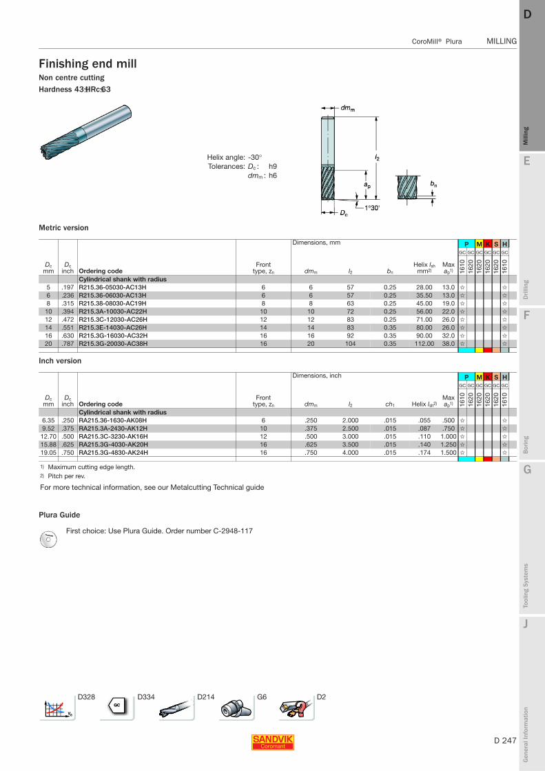
E
D 247
Mill
ing
Drilli
ng
F
Bor
ing
G
Tool
ing
Syst
ems
J
Gen
eral
Info
rmat
ion
DD
Mill
ing
CoroMill® Plura MILLING
MILLING CoroMill® Plura
Finishing end millNon centre cuttingHardness 43≤HRc≤63
Metric version
Inch version
Plura Guide
Helix angle: -30°Tolerances: Dc : h9
dmm : h6
Dimensions, mm P M K S H
Dc mm
Dc inch Ordering code
Front type, zn dmm l2 bn
Helix lsh mm2)
Max ap1)
GC GC GC GC GC GC
1610
1620
1620
1620
1620
1610
Cylindrical shank with radius5 .197 R215.36-05030-AC13H 6 6 57 0.25 28.00 13.0 ✩ ✩
6 .236 R215.36-06030-AC13H 6 6 57 0.25 35.50 13.0 ✩ ✩
8 .315 R215.38-08030-AC19H 8 8 63 0.25 45.00 19.0 ✩ ✩
10 .394 R215.3A-10030-AC22H 10 10 72 0.25 56.00 22.0 ✩ ✩
12 .472 R215.3C-12030-AC26H 12 12 83 0.25 71.00 26.0 ✩ ✩
14 .551 R215.3E-14030-AC26H 14 14 83 0.35 80.00 26.0 ✩ ✩
16 .630 R215.3G-16030-AC32H 16 16 92 0.35 90.00 32.0 ✩ ✩
20 .787 R215.3G-20030-AC38H 16 20 104 0.35 112.00 38.0 ✩ ✩
Dimensions, inch P M K S H
Dc mm
Dc inch Ordering code
Front type, zn dmm l2 ch1 Helix lsh2)
Max ap1)
GC GC GC GC GC GC
1610
1620
1620
1620
1620
1610
Cylindrical shank with radius6.35 .250 RA215.36-1630-AK08H 6 .250 2.000 .015 .055 .500 ✩ ✩
9.52 .375 RA215.3A-2430-AK12H 10 .375 2.500 .015 .087 .750 ✩ ✩
12.70 .500 RA215.3C-3230-AK16H 12 .500 3.000 .015 .110 1.000 ✩ ✩
15.88 .625 RA215.3G-4030-AK20H 16 .625 3.500 .015 .140 1.250 ✩ ✩
19.05 .750 RA215.3G-4830-AK24H 16 .750 4.000 .015 .174 1.500 ✩ ✩
1) Maximum cutting edge length.2) Pitch per rev.
For more technical information, see our Metalcutting Technical guide
First choice: Use Plura Guide. Order number C-2948-117
D328 D334 D214 G6 D2

D 248
MILLING CoroMill® Plura
E
Mill
ing
Drilli
ng
F
Bor
ing
G
Tool
ing
Syst
ems
J
Gen
eral
Info
rmat
ion
DDM
illin
g
MILLING CoroMill® Plura
Corner radius end millCentre cuttingHardness 43≤HRc≤63
Metric version
Plura Guide
Helix angle: -30°Tolerances: Dc : h7
dmm : h5
Dimensions, mm P M K N S H
Dc mm
Dc inch Ordering code
Front type, zn dmm l2 l3 rε
Helix lsh mm2) D4
Max ap1)
GC GC GC GC GC GC GC GC
1610
1620
1620
1620
1620
1620
1610
1620
Cylindrical shank with radius2 .079 R216.22-02030AAI20G 2 6 57 18 0.2 11.20 2.0 ✩ ✩
3 .118 R216.22-03030BAI03G 2 6 57 19 0.5 18.00 3.0 ✩ ✩
4 .157 R216.22-04030BAI04G 2 6 57 20 0.5 22.40 4.0 ✩ ✩
5 .197 R216.22-05030BAI05G 2 6 57 20 0.5 28.00 4.7 5.0 ✩ ✩
6 .236 R216.22-06030CAI06G 2 8 57 21 1 35.50 5.7 6.0 ✩ ✩
8 .315 R216.22-08030CAI08G 2 10 63 27 1 45.00 7.7 8.0 ✩ ✩
10 .394 R216.22-10030DAI10G 2 12 72 32 1.5 56.00 9.7 10.0 ✩ ✩
12 .472 R216.22-12030DAI12G 2 12 83 36 1.5 71.00 11.7 12.0 ✩ ✩
6 .236 R216.24-06030CAI06G 4 8 57 21 1 35.50 5.7 6.0 ✩ ✩
8 .315 R216.24-08030CAI08G 4 8 63 27 1 45.00 7.7 8.0 ✩ ✩
10 .394 R216.24-10030DAI10G 4 10 72 32 1.5 56.00 9.7 10.0 ✩ ✩
12 .472 R216.24-12030DAI12G 4 12 83 36 1.5 71.00 11.7 12.0 ✩ ✩
16 .630 R216.24-16030EAI16G 4 16 92 42 2 90.00 15.5 16.0 ✩ ✩
2 .079 R216.22-02030AAJ20G 2 6 72 20 0.2 11.20 1.9 2.0 ✩ ✩
3 .118 R216.22-03030AAJ03G 2 6 72 20 0.3 18.00 2.9 3.0 ✩ ✩
4 .157 R216.24-04030AAJ04G 4 6 72 20 0.4 22.40 3.8 4.0 ✩ ✩
5 .197 R216.24-05030BAJ05G 4 6 72 20 0.5 28.00 4.7 5.0 ✩ ✩
6 .236 R216.24-06030BAJ06G 4 6 72 24 0.5 35.50 5.7 6.0 ✩ ✩
8 .315 R216.24-08030BAJ08G 4 8 80 29 0.5 45.00 7.7 8.0 ✩ ✩
8 .315 R216.24-08030CAJ08G 4 8 80 29 1 45.00 7.7 8.0 ✩ ✩
8 .315 R216.24-08030DAJ08G 4 8 80 29 1.5 45.00 7.7 8.0 ✩ ✩
10 .394 R216.24-10030BAJ10G 4 10 100 35 0.5 56.00 9.7 10.0 ✩ ✩
10 .394 R216.24-10030CAJ10G 4 10 100 35 1 56.00 9.7 10.0 ✩ ✩
12 .472 R216.24-12030BAJ12G 4 12 100 36 0.5 71.00 11.7 12.0 ✩ ✩
12 .472 R216.24-12030CAJ12G 4 12 100 36 1 71.00 11.7 12.0 ✩ ✩
12 .472 R216.24-12030EAJ12G 4 12 100 36 2 71.00 11.7 12.0 ✩ ✩
1) Maximum cutting edge length.2) Pitch per rev.
For more technical information, see our Metalcutting Technical guide
First choice: Use Plura Guide. Order number C-2948-117
D328 D334 D214 G6 D2

E
D 249
Mill
ing
Drilli
ng
F
Bor
ing
G
Tool
ing
Syst
ems
J
Gen
eral
Info
rmat
ion
DD
Mill
ing
CoroMill® Plura MILLING
MILLING CoroMill® Plura
Corner radius end millCentre cuttingHardness from 43HRc to 58HRc
Inch version
Plura Guide
Helix angle: -30°Tolerances: Dc : h7
dmm : h5
Dimensions, inch P H
Dc mm
Dc inch Ordering code
Front type, zn dmm l2 l3 D4 rε Helix lsh2)
Max ap1)
GC GC
1610
1610
Cylindrical shank with radius3.18 .125 RA216.24-0830BAK02G 4 .250 3.000 .750 .120 .031 .028 .125 ✩ ✩
3.96 .156 RA216.24-1030BAK02G 4 .250 3.000 .750 .150 .031 .055 .156 ✩ ✩
4.78 .188 RA216.24-1230DAK03G 4 .250 3.000 .750 .182 .062 .043 .188 ✩ ✩
6.35 .250 RA216.24-1630DAK04G 4 .250 3.000 1.000 .242 .062 .055 .250 ✩ ✩
9.52 .375 RA216.24-2430DAK06G 4 .375 3.500 1.250 .365 .062 .087 .375 ✩ ✩
9.52 .375 RA216.24-2430HAK06G 4 .375 3.500 1.250 .365 .125 .087 .375 ✩ ✩
12.70 .500 RA216.24-3230HAK08G 4 .500 4.000 1.500 .485 .125 .110 .500 ✩ ✩
1) Maximum cutting edge length.2) Pitch per rev.
For more technical information, see our Metalcutting Technical guide
First choice: Use Plura Guide. Order number C-2948-117
D328 D334 D214 G6 D2

D 250
MILLING CoroMill® Plura
E
Mill
ing
Drilli
ng
F
Bor
ing
G
Tool
ing
Syst
ems
J
Gen
eral
Info
rmat
ion
DDM
illin
g
MILLING CoroMill® Plura
Corner radius end millCentre cuttingHardness 43≤HRc≤63
Metric version
Plura Guide
Helix angle: -30°Tolerances: Dc : h7
dmm : h5
Dimensions, mm P H
Dc mm
Dc inch Ordering code
Front type, zn dmm l2 l3 l22 rε
Helix lsh mm2)
Max ap1)
GC GC
1610
1610
Cylindrical shank with radius, extra long3 .118 R216.22-03030BAP03G 2 6 80 4 38.4 0.5 16.00 3.0 ✩ ✩
4 .157 R216.22-04030BAP04G 2 6 90 5 50.8 0.5 22.40 4.0 ✩ ✩
6 .236 R216.22-06030BAP06G 2 10 100 7 52.8 0.5 35.50 6.0 ✩ ✩
6 .236 R216.24-06030CAP06G 4 8 100 7 52.8 1 35.50 6.0 ✩ ✩
8 .315 R216.24-08030CAP08G 4 10 100 10 53.0 1 5.00 8.0 ✩ ✩
10 .394 R216.24-10030CAP10G 4 12 125 12 57.8 1 56.00 10.0 ✩ ✩
10 .394 R216.24-10030GAP10G 4 12 125 12 57.8 3 56.00 10.0 ✩ ✩
12 .472 R216.24-12030CAP12G 4 14 140 14 59.8 1 71.00 12.0 ✩ ✩
12 .472 R216.24-12030GAP12G 4 14 140 14 59.8 3 71.00 12.0 ✩ ✩
16 .630 R216.24-16030CAP16G 4 16 150 18 63.9 1 90.00 16.0 ✩ ✩
16 .630 R216.24-16030GAP16G 4 16 150 18 63.9 3 90.00 16.0 ✩ ✩
1) Maximum cutting edge length.2) Pitch per rev.
For more technical information, see our Metalcutting Technical guide
First choice: Use Plura Guide. Order number C-2948-117
D328 D334 D214 G6 D2

E
D 251
Mill
ing
Drilli
ng
F
Bor
ing
G
Tool
ing
Syst
ems
J
Gen
eral
Info
rmat
ion
DD
Mill
ing
CoroMill® Plura MILLING
MILLING CoroMill® Plura
General purpose end millCentre cuttingHardness <63 HRc
Metric version
Plura Guide
Helix angle: -30°Tolerances: Dc : h10
dmm : h6
Dimensions, mm P M K N S H
Dc mm
Dc inch Ordering code
Front type, zn dmm l2 l3 D4
Helix lsh mm2)
Max ap1)
GC GC GC GC GC GC GC GC GC GC
1620
1630
1620
1630
1620
1630
1620
1620
1630
1620
Cylindrical shank, 2.5 x Dc
0.4 .016 R216.32-00430-AE04G 2 6 54 1 0.36 2.24 0.4 ✩ ✩ ✩ ✩ ✩ ✩
0.5 .020 R216.32-00530-AE05G 2 6 54 1.2 0.46 2.80 0.5 ✩ ✩ ✩ ✩ ✩ ✩
0.6 .024 R216.32-00630-AE06G 2 6 54 1.5 0.56 3.55 0.6 ✩ ✩ ✩ ✩ ✩ ✩
0.8 .032 R216.32-00830-AE08G 2 6 54 2 0.76 4.50 0.8 ✩ ✩ ✩ ✩ ✩ ✩
1 .039 R216.32-01030-AE10G 2 6 54 2.5 0.96 5.60 1.0 ✩ ✩ ✩ ✩ ✩ ✩
Cylindrical shank, 10 x Dc
0.5 .020 R216.32-00530-AI05G 2 6 57 2.5 0.46 2.80 0.5 ✩ ✩ ✩ ✩ ✩ ✩
0.6 .024 R216.32-00630-AI06G 2 6 57 3 0.56 3.55 0.6 ✩ ✩ ✩ ✩ ✩ ✩
0.8 .032 R216.32-00830-AI08G 2 6 57 4 0.76 4.50 0.8 ✩ ✩ ✩ ✩ ✩ ✩
1 .039 R216.32-01030-AI10G 2 6 57 5 0.96 5.60 1.0 ✩ ✩ ✩ ✩ ✩ ✩
Cylindrical shank, 5 x Dc
0.5 .020 R216.32-00530-AJ05G 2 6 57 5 0.46 2.80 0.5 ✩ ✩ ✩ ✩ ✩ ✩
0.6 .024 R216.32-00630-AJ06G 2 6 57 6 0.56 3.55 0.6 ✩ ✩ ✩ ✩ ✩ ✩
0.8 .032 R216.32-00830-AJ08G 2 6 57 8 0.76 4.50 0.8 ✩ ✩ ✩ ✩ ✩ ✩
1 .039 R216.32-01030-AJ10G 2 6 57 10 0.96 5.60 1.0 ✩ ✩ ✩ ✩ ✩ ✩
1) Maximum cutting edge length.2) Pitch per rev.
For more technical information, see our Metalcutting Technical guide
First choice: Use Plura Guide. Order number C-2948-117
D328 D334 D214 G6 D2
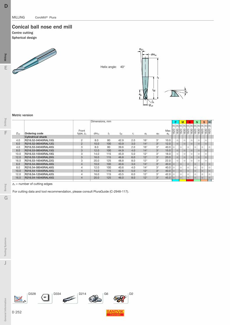
D 252
MILLING CoroMill® Plura
E
Mill
ing
Drilli
ng
F
Bor
ing
G
Tool
ing
Syst
ems
J
Gen
eral
Info
rmat
ion
DDM
illin
g
MILLING CoroMill® Plura
Conical ball nose end millCentre cuttingSpherical design
Metric version
Helix angle: 40°
Dimensions, mm P M K N S H
Dc2 Ordering codeFront
type, zn dmm l2 l22 rε αo α21
Max ap
GC GC GC GC GC GC GC GC GC GC GC
1620
1630
1620
1630
1620
1630
1620
1630
1620
1630
1620
Cylindrical shank4.0 R216.52-04040RAL10G 2 8.0 80 42.9 2.0 16° 3° 10.0 ✩ ✩ ✩ ✩ ✩
6.0 R216.52-06040RAL12G 2 10.0 100 43.9 3.0 14° 3° 12.0 ✩ ✩ ✩ ✩ ✩
4.0 R216.53-04040RAL40G 3 8.0 80 39.6 2.0 16° 3° 40.0 ✩ ✩ ✩ ✩ ✩ ✩
8.0 R216.53-08040RAL15G 3 12.0 100 44.9 4.0 14° 3° 15.0 ✩ ✩ ✩ ✩ ✩
10.0 R216.53-10040RAL18G 3 14.0 115 45.9 5.0 12° 3° 18.0 ✩ ✩ ✩ ✩ ✩
12.0 R216.53-12040RAL20G 3 16.0 115 46.8 6.0 12° 3° 20.0 ✩ ✩ ✩ ✩ ✩
16.0 R216.53-16040RAL22G 3 20.0 125 48.8 8.0 12° 3° 22.0 ✩ ✩ ✩ ✩ ✩
6.0 R216.54-06040RAL40G 4 10.0 100 40.6 3.0 14° 3° 40.0 ✩ ✩ ✩ ✩ ✩ ✩
8.0 R216.54-08040RAL40G 4 12.0 100 40.6 4.0 14° 3° 40.0 ✩ ✩ ✩ ✩ ✩ ✩
10.0 R216.54-10040RAL40G 4 14.0 115 42.6 5.0 12° 3° 40.0 ✩ ✩ ✩ ✩ ✩ ✩
12.0 R216.54-12040RAL42G 4 16.0 115 43.5 6.0 12° 3° 42.0 ✩ ✩ ✩ ✩ ✩ ✩
16.0 R216.54-16040RAL45G 4 20.0 125 46.0 8.0 12° 3° 45.0 ✩ ✩ ✩ ✩ ✩ ✩
zn = number of cutting edges
For cutting data and tool recommendation, please consult PluraGuide (C-2948-117).
D328 D334 D214 G6 D2

E
D 253
Mill
ing
Drilli
ng
F
Bor
ing
G
Tool
ing
Syst
ems
J
Gen
eral
Info
rmat
ion
DD
Mill
ing
CoroMill® Plura MILLING
MILLING CoroMill® Plura
Ball nose end millHardness 43HRc to 63HRc
Inch version
Plura Guide
Helix angle: -30°Tolerances: Dc2 : h7
dmm : h5
Dimensions, inch P M K N S H
Dc mm
Dc inch Ordering code
Front type, zn dmm l2 l3 rε
Max ap1)
GC GC GC GC GC GC GC GC
1610
1620
1620
1620
1620
1620
1610
1620
Cylindrical shank1.57 .062 RA216.42-0430-AK08G 2 .250 3.000 .250 .031 .125 ✩ ✩
3.18 .125 RA216.42-0830-AK04G 2 .250 3.000 .500 .062 .250 ✩ ✩
2.36 .093 RA216.42-0630-AK12G 2 .250 3.000 .375 .046 .187 ✩ ✩
3.96 .156 RA216.42-1030-AK05G 2 .250 3.000 .650 .078 .312 ✩ ✩
4.75 .187 RA216.42-1230-AK06G 2 .250 3.000 .750 .093 .375 ✩ ✩
6.35 .250 RA216.42-1630-AK08G 2 .250 3.000 .125 .500 ✩ ✩
7.92 .312 RA216.42-2030-AK10G 2 .375 3.500 1.250 .156 .625 ✩ ✩
9.53 .375 RA216.42-2430-AK12G 2 .375 3.500 .188 .750 ✩ ✩
12.70 .500 RA216.42-3230-AK16G 2 .500 4.000 .250 1.000 ✩ ✩
1) Maximum cutting edge length.
For more technical information, see our Metalcutting Technical guide
First choice: Use Plura Guide. Order number C-2948-117
D328 D334 D214 G6 D2
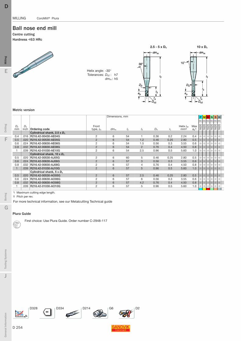
D 254
MILLING CoroMill® Plura
E
Mill
ing
Drilli
ng
F
Bor
ing
G
Tool
ing
Syst
ems
J
Gen
eral
Info
rmat
ion
DDM
illin
g
MILLING CoroMill® Plura
Ball nose end millCentre cuttingHardness <63 HRc
Metric version
Plura Guide
2.5 - 5 x Dc 10 x Dc
Helix angle: -30°Tolerances: Dc2 : h7
dmm : h5
Dimensions, mm P M K N S H
Dc mm
Dc inch Ordering code
Front type, zn dmm l2 l3 D4 rε
Helix lsh mm2)
Max ap1)
GC GC GC GC GC GC
1620
1620
1620
1620
1620
1620
Cylindrical shank, 2.5 x Dc
0.4 .016 R216.42-00430-AE04G 2 6 54 1 0.36 0.2 2.24 0.4 ✩ ✩ ✩ ✩ ✩ ✩
0.5 .020 R216.42-00530-AE05G 2 6 54 1.2 0.46 0.25 2.80 0.5 ✩ ✩ ✩ ✩ ✩ ✩
0.6 .024 R216.42-00630-AE06G 2 6 54 1.5 0.56 0.3 3.55 0.6 ✩ ✩ ✩ ✩ ✩ ✩
0.8 .032 R216.42-00830-AE08G 2 6 54 2 0.76 0.4 4.50 0.8 ✩ ✩ ✩ ✩ ✩ ✩
1 .039 R216.42-01030-AE10G 2 6 54 2.5 0.96 0.5 5.60 1.0 ✩ ✩ ✩ ✩ ✩ ✩
Cylindrical shank, 10 x Dc
0.5 .020 R216.42-00530-AJ05G 2 6 60 5 0.46 0.25 2.80 0.5 ✩ ✩ ✩ ✩ ✩ ✩
0.6 .024 R216.42-00630-AJ06G 2 6 57 3 0.56 0.3 3.55 0.6 ✩ ✩ ✩ ✩ ✩ ✩
0.8 .032 R216.42-00830-AJ08G 2 6 57 4 0.76 0.4 4.50 0.8 ✩ ✩ ✩ ✩ ✩ ✩
1 .039 R216.42-01030-AJ10G 2 6 57 5 0.96 0.5 5.60 1.0 ✩ ✩ ✩ ✩ ✩ ✩
Cylindrical shank, 5 x Dc
0.5 .020 R216.42-00530-AO05G 2 6 57 2.5 0.46 0.25 2.80 0.5 ✩ ✩ ✩ ✩ ✩ ✩
0.6 .024 R216.42-00630-AO06G 2 6 57 6 0.56 0.3 3.55 0.6 ✩ ✩ ✩ ✩ ✩ ✩
0.8 .032 R216.42-00830-AO08G 2 6 57 4.2 0.76 0.4 4.50 0.8 ✩ ✩ ✩ ✩ ✩ ✩
1 .039 R216.42-01030-AO10G 2 6 57 5 0.96 0.5 5.60 1.0 ✩ ✩ ✩ ✩ ✩ ✩
1) Maximum cutting edge length.2) Pitch per rev.
For more technical information, see our Metalcutting Technical guide
First choice: Use Plura Guide. Order number C-2948-117
D328 D334 D214 G6 D2

E
D 255
Mill
ing
Drilli
ng
F
Bor
ing
G
Tool
ing
Syst
ems
J
Gen
eral
Info
rmat
ion
DD
Mill
ing
CoroMill® Plura MILLING
MILLING CoroMill® Plura
Ball nose end millHardness 43≤HRc≤63
Metric version
Plura Guide
Helix angle: -30°Tolerances: dmm : h5
Dc2 : h7
Dimensions, mm P M K N S H
Dc2 mm
Dc2 inch Ordering code
Front type, zn dmm l2 rε
Helix lsh mm2) αo
Max ap1)
- - - - - -
P10
P10
P10
P10
P10
P10
Cylindrical shank, extra long3 .118 R216.42-03030-AQ05G 2 3 100 1.5 18.00 20 5.0 ✩ ✩ ✩ ✩ ✩ ✩
4 .157 R216.42-04030-AQ06G 2 4 100 2 22.40 14 6.0 ✩ ✩ ✩ ✩ ✩ ✩
6 .236 R216.42-06030-AQ09G 2 6 125 3 35.50 14 9.0 ✩ ✩ ✩ ✩ ✩ ✩
8 .315 R216.42-08030-AQ12G 2 8 150 4 45.00 14 12.0 ✩ ✩ ✩ ✩ ✩ ✩
10 .394 R216.42-10030-AQ15G 2 10 150 5 56.00 12 15.0 ✩ ✩ ✩ ✩ ✩ ✩
12 .472 R216.42-12030-AQ18G 2 12 150 6 71.00 12 18.0 ✩ ✩ ✩ ✩ ✩ ✩
1) Maximum cutting edge length.2) Pitch per rev.
zn = number of cutting edges
Cutting dataFirst choice: Use Plura Guide. Order number C-2948-117
D328 D334 D214 G6 D2
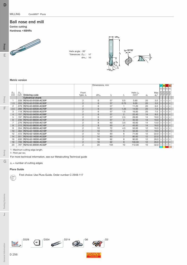
D 256
MILLING CoroMill® Plura
E
Mill
ing
Drilli
ng
F
Bor
ing
G
Tool
ing
Syst
ems
J
Gen
eral
Info
rmat
ion
DDM
illin
g
MILLING CoroMill® Plura
Ball nose end millCentre cuttingHardness <48HRc
Metric version
Plura Guide
Helix angle: -30°Tolerances: Dc2 : h7
dmm : h5
Dimensions, mm P M K S
Dc2 mm
Dc2 inch Ordering code
Front type, zn dmm l2 rε
Helix lsh mm2) αo
Max ap1)
GC GC GC GC
1620
1620
1620
1620
Cylindrical shank1 .039 R216.42-01030-AC30P 2 6 57 0.5 5.60 20 3.0 ✩ ✩ ✩ ✩
1.5 .059 R216.42-01530-AC30P 2 6 57 0.75 9.00 20 3.0 ✩ ✩ ✩ ✩
2 .079 R216.42-02030-AC60P 2 6 57 1 11.20 20 6.0 ✩ ✩ ✩ ✩
2.5 .098 R216.42-02530-AC70P 2 6 57 1.25 14.00 20 7.0 ✩ ✩ ✩ ✩
3 .118 R216.42-03030-AC07P 2 6 57 1.5 16.00 20 7.0 ✩ ✩ ✩ ✩
4 .157 R216.42-04030-AC08P 2 6 57 2 22.40 14 8.0 ✩ ✩ ✩ ✩
5 .197 R216.42-05030-AC10P 2 6 57 2.5 28.00 14 10.0 ✩ ✩ ✩ ✩
6 .236 R216.42-06030-AC10P 2 6 57 3 35.50 14 10.0 ✩ ✩ ✩ ✩
7 .276 R216.42-07030-AC13P 2 8 63 3.5 40.00 14 13.0 ✩ ✩ ✩ ✩
8 .315 R216.42-08030-AC16P 2 8 63 4 45.00 14 16.0 ✩ ✩ ✩ ✩
9 .354 R216.42-09030-AC16P 2 10 72 4.5 50.00 12 16.0 ✩ ✩ ✩ ✩
10 .394 R216.42-10030-AC19P 2 10 72 5 56.00 12 19.0 ✩ ✩ ✩ ✩
12 .472 R216.42-12030-AC22P 2 12 83 6 71.00 12 22.0 ✩ ✩ ✩ ✩
14 .551 R216.42-14030-AC22P 2 14 83 7 80.00 12 22.0 ✩ ✩ ✩ ✩
16 .630 R216.42-16030-AC26P 2 16 92 8 90.00 12 26.0 ✩ ✩ ✩ ✩
18 .709 R216.42-18030-AC26P 2 18 92 9 100.00 12 26.0 ✩ ✩ ✩ ✩
20 .787 R216.42-20030-AC32P 2 20 104 10 112.00 10 32.0 ✩ ✩ ✩ ✩
1) Maximum cutting edge length.2) Pitch per rev.
For more technical information, see our Metalcutting Technical guide
zn = number of cutting edges
First choice: Use Plura Guide. Order number C-2948-117
D328 D334 D214 G6 D2
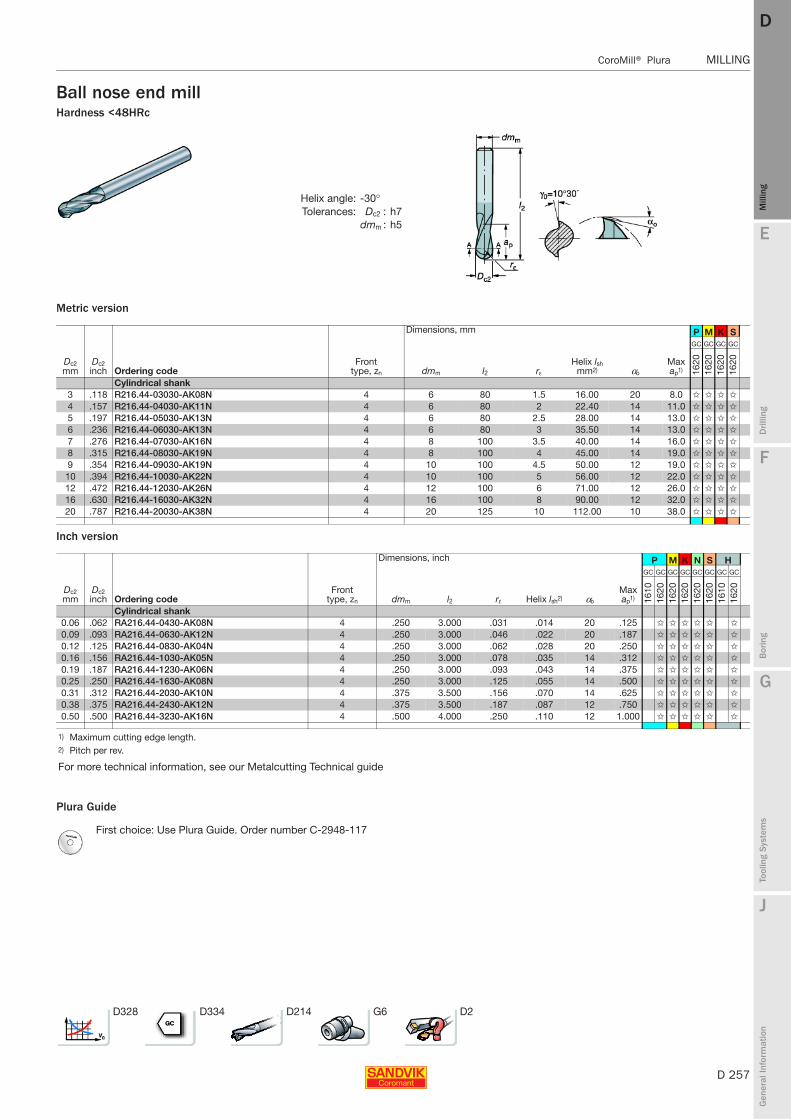
E
D 257
Mill
ing
Drilli
ng
F
Bor
ing
G
Tool
ing
Syst
ems
J
Gen
eral
Info
rmat
ion
DD
Mill
ing
CoroMill® Plura MILLING
MILLING CoroMill® Plura
Ball nose end millHardness <48HRc
Metric version
Inch version
Plura Guide
Helix angle: -30°Tolerances: Dc2 : h7
dmm : h5
Dimensions, mm P M K S
Dc2 mm
Dc2 inch Ordering code
Front type, zn dmm l2 rε
Helix lsh mm2) αo
Max ap1)
GC GC GC GC
1620
1620
1620
1620
Cylindrical shank3 .118 R216.44-03030-AK08N 4 6 80 1.5 16.00 20 8.0 ✩ ✩ ✩ ✩
4 .157 R216.44-04030-AK11N 4 6 80 2 22.40 14 11.0 ✩ ✩ ✩ ✩
5 .197 R216.44-05030-AK13N 4 6 80 2.5 28.00 14 13.0 ✩ ✩ ✩ ✩
6 .236 R216.44-06030-AK13N 4 6 80 3 35.50 14 13.0 ✩ ✩ ✩ ✩
7 .276 R216.44-07030-AK16N 4 8 100 3.5 40.00 14 16.0 ✩ ✩ ✩ ✩
8 .315 R216.44-08030-AK19N 4 8 100 4 45.00 14 19.0 ✩ ✩ ✩ ✩
9 .354 R216.44-09030-AK19N 4 10 100 4.5 50.00 12 19.0 ✩ ✩ ✩ ✩
10 .394 R216.44-10030-AK22N 4 10 100 5 56.00 12 22.0 ✩ ✩ ✩ ✩
12 .472 R216.44-12030-AK26N 4 12 100 6 71.00 12 26.0 ✩ ✩ ✩ ✩
16 .630 R216.44-16030-AK32N 4 16 100 8 90.00 12 32.0 ✩ ✩ ✩ ✩
20 .787 R216.44-20030-AK38N 4 20 125 10 112.00 10 38.0 ✩ ✩ ✩ ✩
Dimensions, inch P M K N S H
Dc2 mm
Dc2 inch Ordering code
Front type, zn dmm l2 rε Helix lsh2) αo
Max ap1)
GC GC GC GC GC GC GC GC
1610
1620
1620
1620
1620
1620
1610
1620
Cylindrical shank0.06 .062 RA216.44-0430-AK08N 4 .250 3.000 .031 .014 20 .125 ✩ ✩ ✩ ✩ ✩ ✩
0.09 .093 RA216.44-0630-AK12N 4 .250 3.000 .046 .022 20 .187 ✩ ✩ ✩ ✩ ✩ ✩
0.12 .125 RA216.44-0830-AK04N 4 .250 3.000 .062 .028 20 .250 ✩ ✩ ✩ ✩ ✩ ✩
0.16 .156 RA216.44-1030-AK05N 4 .250 3.000 .078 .035 14 .312 ✩ ✩ ✩ ✩ ✩ ✩
0.19 .187 RA216.44-1230-AK06N 4 .250 3.000 .093 .043 14 .375 ✩ ✩ ✩ ✩ ✩ ✩
0.25 .250 RA216.44-1630-AK08N 4 .250 3.000 .125 .055 14 .500 ✩ ✩ ✩ ✩ ✩ ✩
0.31 .312 RA216.44-2030-AK10N 4 .375 3.500 .156 .070 14 .625 ✩ ✩ ✩ ✩ ✩ ✩
0.38 .375 RA216.44-2430-AK12N 4 .375 3.500 .187 .087 12 .750 ✩ ✩ ✩ ✩ ✩ ✩
0.50 .500 RA216.44-3230-AK16N 4 .500 4.000 .250 .110 12 1.000 ✩ ✩ ✩ ✩ ✩ ✩
1) Maximum cutting edge length.2) Pitch per rev.
For more technical information, see our Metalcutting Technical guide
First choice: Use Plura Guide. Order number C-2948-117
D328 D334 D214 G6 D2

D 258
MILLING CoroMill® Plura
E
Mill
ing
Drilli
ng
F
Bor
ing
G
Tool
ing
Syst
ems
J
Gen
eral
Info
rmat
ion
DDM
illin
g
MILLING CoroMill® Plura
Ball nose end millCentre cutting
Metric version
Plura Guide
Helix angle: -30°Tolerances: Dc : h9
dmm : h5
Dimensions, mm N
Dc2 mm
Dc2 inch Ordering code
Front type, zn dmm l2 rε
Helix lsh mm2) αo
Max ap1)
-
H10
F
Cylindrical shank2 .079 R216.42-02030-AK60A 2 6 60 1 11.20 20 6.0 ✩
3 .118 R216.42-03030-AK07A 2 6 80 1.5 18.00 20 7.0 ✩
4 .157 R216.42-04030-AK08A 2 6 80 2 22.40 14 8.0 ✩
5 .197 R216.42-05030-AK10A 2 6 80 2.5 28.00 14 10.0 ✩
6 .236 R216.42-06030-AK10A 2 6 80 3 35.50 14 10.0 ✩
8 .315 R216.42-08030-AK16A 2 8 100 4 45.00 14 16.0 ✩
10 .394 R216.42-10030-AK19A 2 10 100 5 56.00 12 19.0 ✩
12 .472 R216.42-12030-AK22A 2 12 100 6 71.00 12 22.0 ✩
16 .630 R216.42-16030-AK26A 2 16 100 8 90.00 12 26.0 ✩
1) Maximum cutting edge length.2) Pitch per rev.
For more technical information, see our Metalcutting Technical guide
First choice: Use Plura Guide. Order number C-2948-117
D328 D334 D214 G6 D2

E
D 259
Mill
ing
Drilli
ng
F
Bor
ing
G
Tool
ing
Syst
ems
J
Gen
eral
Info
rmat
ion
DD
Mill
ing
CoroMill® Plura MILLING
MILLING CoroMill® Plura
Ball nose end millHardness <48HRc
Inch version
Plura Guide
Helix angle: -30°Tolerances: Dc2 : h7
dmm : h5
Dimensions, inch P M K N S H
Dc2 mm
Dc2 inch Ordering code
Front type, zn dmm l2 rε Helix lsh2) αo
Max ap1)
GC GC GC GC GC GC GC GC
1610
1620
1620
1620
1620
1620
1610
1620
Cylindrical shank, short1.57 .062 RA216.42-0430-AK08P 2 .250 3.000 .031 .014 20 .125 ✩ ✩ ✩ ✩ ✩ ✩
2.36 .093 RA216.42-0630-AK12P 2 .250 3.000 .046 .022 20 .187 ✩ ✩ ✩ ✩ ✩ ✩
3.18 .125 RA216.42-0830-AK04P 2 .250 3.000 .062 .028 20 .250 ✩ ✩ ✩ ✩ ✩
3.96 .156 RA216.42-1030-AK05P 2 .250 3.000 .078 .035 14 .312 ✩ ✩ ✩ ✩ ✩ ✩
4.75 .187 RA216.42-1230-AK06P 2 .250 3.000 .093 .043 14 .375 ✩ ✩ ✩ ✩ ✩ ✩
6.35 .250 RA216.42-1630-AK08P 2 .250 3.000 .125 .055 14 .500 ✩ ✩ ✩ ✩ ✩ ✩
7.92 .312 RA216.42-2030-AK10P 2 .375 3.500 .156 .070 14 .625 ✩ ✩ ✩ ✩ ✩ ✩
9.52 .375 RA216.42-2430-AK12P 2 .375 3.500 .187 .087 12 .750 ✩ ✩ ✩ ✩ ✩ ✩
12.70 .500 RA216.42-3230-AK16P 2 .500 4.000 .250 .110 12 1.000 ✩ ✩ ✩ ✩ ✩ ✩
Cylindrical shank, long1.57 .062 RA216.42-0430-AS08P 2 .250 2.000 .031 .014 20 .125 ✩ ✩ ✩ ✩ ✩ ✩
2.36 .093 RA216.42-0630-AS12P 2 .250 2.000 .046 .022 20 .187 ✩ ✩ ✩ ✩ ✩
3.18 .125 RA216.42-0830-AS04P 2 .250 2.000 .062 .028 20 .250 ✩ ✩ ✩ ✩ ✩ ✩
3.96 .156 RA216.42-1030-AS05P 2 .250 2.000 .078 .035 14 .312 ✩ ✩ ✩ ✩ ✩ ✩
4.75 .187 RA216.42-1230-AS06P 2 .250 2.000 .093 .043 14 .375 ✩ ✩ ✩ ✩ ✩ ✩
6.35 .250 RA216.42-1630-AS08P 2 .250 2.000 .125 .055 14 .500 ✩ ✩ ✩ ✩ ✩ ✩
7.92 .312 RA216.42-2030-AS10P 2 .375 2.500 .156 .070 14 .625 ✩ ✩ ✩ ✩ ✩ ✩
9.52 .375 RA216.42-2430-AS12P 2 .375 2.500 .187 .087 12 .750 ✩ ✩ ✩ ✩ ✩ ✩
12.70 .500 RA216.42-3230-AS16P 2 .500 3.000 .250 .110 12 1.000 ✩ ✩ ✩ ✩ ✩ ✩
1) Maximum cutting edge length.2) Pitch per rev.
For more technical information, see our Metalcutting Technical guide
First choice: Use Plura Guide. Order number C-2948-117
D328 D334 D214 G6 D2
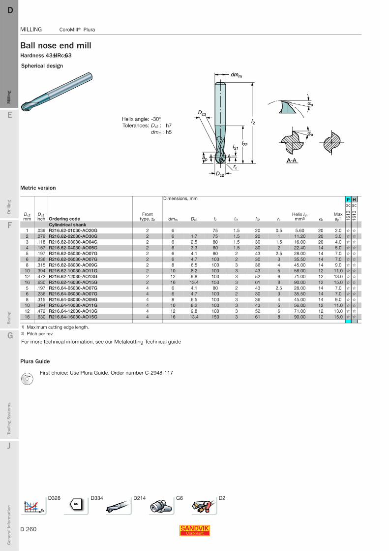
D 260
MILLING CoroMill® Plura
E
Mill
ing
Drilli
ng
F
Bor
ing
G
Tool
ing
Syst
ems
J
Gen
eral
Info
rmat
ion
DDM
illin
g
MILLING CoroMill® Plura
Ball nose end millHardness 43≤HRc≤63
Metric version
Plura Guide
Spherical design
Helix angle: -30°Tolerances: Dc2 : h7
dmm : h5
Dimensions, mm P H
Dc2 mm
Dc2 inch Ordering code
Front type, zn dmm Dc3 l2 l21 l22 rε
Helix lsh mm2) αo
Max ap1)
GC GC
1610
1610
Cylindrical shank1 .039 R216.62-01030-AO20G 2 6 75 1.5 20 0.5 5.60 20 2.0 ✩ ✩
2 .079 R216.62-02030-AO30G 2 6 1.7 75 1.5 20 1 11.20 20 3.0 ✩ ✩
3 .118 R216.62-03030-AO04G 2 6 2.5 80 1.5 30 1.5 16.00 20 4.0 ✩ ✩
4 .157 R216.62-04030-AO05G 2 6 3.3 80 1.5 30 2 22.40 14 5.0 ✩ ✩
5 .197 R216.62-05030-AO07G 2 6 4.1 80 2 43 2.5 28.00 14 7.0 ✩ ✩
6 .236 R216.62-06030-AO07G 2 6 4.7 100 2 30 3 35.50 14 7.0 ✩ ✩
8 .315 R216.62-08030-AO09G 2 8 6.5 100 3 36 4 45.00 14 9.0 ✩ ✩
10 .394 R216.62-10030-AO11G 2 10 8.2 100 3 43 5 56.00 12 11.0 ✩ ✩
12 .472 R216.62-12030-AO13G 2 12 9.8 100 3 52 6 71.00 12 13.0 ✩ ✩
16 .630 R216.62-16030-AO15G 2 16 13.4 150 3 61 8 90.00 12 15.0 ✩ ✩
5 .197 R216.64-05030-AO07G 4 6 4.1 80 2 43 2.5 28.00 14 7.0 ✩ ✩
6 .236 R216.64-06030-AO07G 4 6 4.7 100 2 30 3 35.50 14 7.0 ✩ ✩
8 .315 R216.64-08030-AO09G 4 8 6.5 100 3 36 4 45.00 14 9.0 ✩ ✩
10 .394 R216.64-10030-AO11G 4 10 8.2 100 3 43 5 56.00 12 11.0 ✩ ✩
12 .472 R216.64-12030-AO13G 4 12 9.8 100 3 52 6 71.00 12 13.0 ✩ ✩
16 .630 R216.64-16030-AO15G 4 16 13.4 150 3 61 8 90.00 12 15.0 ✩ ✩
1) Maximum cutting edge length.2) Pitch per rev.
For more technical information, see our Metalcutting Technical guide
First choice: Use Plura Guide. Order number C-2948-117
D328 D334 D214 G6 D2
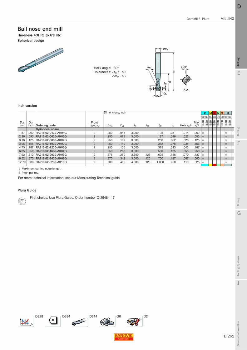
E
D 261
Mill
ing
Drilli
ng
F
Bor
ing
G
Tool
ing
Syst
ems
J
Gen
eral
Info
rmat
ion
DD
Mill
ing
CoroMill® Plura MILLING
MILLING CoroMill® Plura
Ball nose end millHardness 43HRc to 63HRcSpherical design
Inch version
Plura Guide
Helix angle: -30°Tolerances: Dc2 : h9
dmm : h6
Dimensions, inch P M K N S H
Dc2 mm
Dc2 inch Ordering code
Front type, zn dmm Dc3 l2 l21 l22 rε Helix lsh2)
Max ap1)
GC GC GC GC GC GC GC GC
1610
1620
1620
1620
1620
1620
1610
1620
Cylindrical shank1.57 .062 RA216.62-0430-AK04G 2 .250 .046 3.000 .125 .031 .014 .062 ✩ ✩
2.36 .093 RA216.62-0630-AK06G 2 .250 .078 3.000 .187 .046 .022 .093 ✩ ✩
3.18 .125 RA216.62-0830-AK02G 2 .250 .109 3.000 .250 .062 .028 .125 ✩ ✩
3.96 .156 RA216.62-1030-AK02G 2 .250 .140 3.000 .312 .078 .035 .156 ✩ ✩
4.75 .187 RA216.62-1230-AK03G 2 .250 .156 3.000 .375 .093 .043 .187 ✩ ✩
6.35 .250 RA216.62-1630-AK04G 2 .250 .203 3.000 .500 .125 .055 .250 ✩ ✩
7.92 .312 RA216.62-2030-AK07G 2 .375 .250 3.500 .125 .625 .156 .070 .437 ✩ ✩
9.52 .375 RA216.62-2430-AK08G 2 .375 .343 3.500 .125 .750 .187 .087 .500 ✩ ✩
12.70 .500 RA216.62-3230-AK10G 2 .500 .406 4.000 .125 1.000 .250 .110 .625 ✩ ✩
1) Maximum cutting edge length.2) Pitch per rev.
For more technical information, see our Metalcutting Technical guide
First choice: Use Plura Guide. Order number C-2948-117
D328 D334 D214 G6 D2
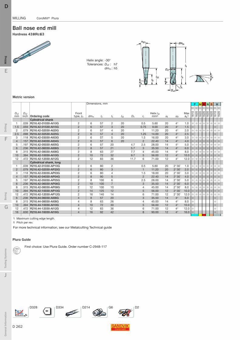
D 262
MILLING CoroMill® Plura
E
Mill
ing
Drilli
ng
F
Bor
ing
G
Tool
ing
Syst
ems
J
Gen
eral
Info
rmat
ion
DDM
illin
g
MILLING CoroMill® Plura
Ball nose end millHardness 43≤HRc≤63
Metric version
Plura Guide
Helix angle: -30°Tolerances: Dc2 : h7
dmm : h5
Dimensions, mm P M K N S H
Dc2 mm
Dc2 inch Ordering code
Front type, zn dmm l2 l3 l22 D4 rε
Helix lsh mm2) αo α21
Max ap1)
GC GC GC GC GC GC GC GC
1610
1620
1620
1620
1620
1620
1610
1620
Cylindrical shank1 .039 R216.42-01030-AI10G 2 6 57 2 20 0.5 5.60 20 4° 1.0 ✩ ✩ ✩ ✩ ✩ ✩ ✩ ✩
1.5 .059 R216.42-01530-AI15G 2 6 57 3 20 0.75 9.00 20 4° 1.5 ✩ ✩
2 .079 R216.42-02030-AI20G 2 6 57 4 20 1 11.20 20 4° 2.0 ✩ ✩ ✩ ✩ ✩ ✩ ✩ ✩
2.5 .098 R216.42-02530-AI25G 2 6 57 4 20 1.25 14.00 20 4° 2.5 ✩ ✩
3 .118 R216.42-03030-AI03G 2 6 57 5 20 1.5 16.00 20 4° 3.0 ✩ ✩ ✩ ✩ ✩ ✩ ✩ ✩
4 .157 R216.42-04030-AI04G 2 6 57 6 20 2 22.40 14 4° 4.0 ✩ ✩ ✩ ✩ ✩ ✩ ✩ ✩
5 .197 R216.42-05030-AI05G 2 6 57 20 4.7 2.5 28.00 14 4° 5.0 ✩ ✩ ✩ ✩ ✩ ✩ ✩ ✩
6 .236 R216.42-06030-AI06G 2 8 57 21 5.7 3 35.50 14 4° 6.0 ✩ ✩ ✩ ✩ ✩ ✩ ✩ ✩
8 .315 R216.42-08030-AI08G 2 8 63 27 7.7 4 45.00 14 4° 8.0 ✩ ✩ ✩ ✩ ✩ ✩ ✩ ✩
10 .394 R216.42-10030-AI10G 2 10 72 32 9.7 5 56.00 12 4° 10.0 ✩ ✩ ✩ ✩ ✩ ✩ ✩ ✩
12 .472 R216.42-12030-AI12G 2 12 83 36 11.7 6 71.00 12 4° 12.0 ✩ ✩ ✩ ✩ ✩ ✩ ✩ ✩
Cylindrical shank, long1 .039 R216.42-01030-AP10G 2 6 80 2 0.5 5.60 20 2° 30´ 1.0 ✩ ✩ ✩ ✩ ✩ ✩ ✩ ✩
2 .079 R216.42-02030-AP20G 2 6 80 3 1 11.20 20 2° 30´ 2.0 ✩ ✩ ✩ ✩ ✩ ✩ ✩ ✩
3 .118 R216.42-03030-AP03G 2 6 80 4 1.5 18.00 20 2° 30´ 3.0 ✩ ✩ ✩ ✩ ✩ ✩ ✩ ✩
4 .157 R216.42-04030-AP04G 2 8 90 5 2 22.40 14 2° 30´ 4.0 ✩ ✩ ✩ ✩ ✩ ✩ ✩ ✩
5 .197 R216.42-05030-AP05G 2 8 100 6 2.5 28.00 14 2° 30´ 5.0 ✩ ✩ ✩ ✩ ✩ ✩ ✩ ✩
6 .236 R216.42-06030-AP06G 2 10 100 7 3 35.50 14 2° 30´ 6.0 ✩ ✩ ✩ ✩ ✩ ✩ ✩ ✩
8 .315 R216.42-08030-AP08G 2 12 100 10 4 45.00 14 2° 30´ 8.0 ✩ ✩ ✩ ✩ ✩ ✩ ✩ ✩
10 .394 R216.42-10030-AP10G 2 14 125 12 5 56.00 12 2° 30´ 10.0 ✩ ✩ ✩ ✩ ✩ ✩ ✩ ✩
12 .472 R216.42-12030-AP12G 2 16 140 14 6 71.00 12 2° 30´ 12.0 ✩ ✩ ✩ ✩ ✩ ✩ ✩ ✩
6 .236 R216.44-06030-AI06G 4 8 57 20 3 35.50 14 4° 6.0 ✩ ✩
8 .315 R216.44-08030-AI08G 4 8 63 26 4 45.00 14 4° 8.0 ✩ ✩
10 .394 R216.44-10030-AI10G 4 10 72 30 5 56.00 12 4° 10.0 ✩ ✩
12 .472 R216.44-12030-AI12G 4 12 83 36 6 71.00 12 4° 12.0 ✩ ✩
16 .630 R216.44-16030-AI16G 4 16 92 42 8 90.00 12 4° 16.0 ✩ ✩
1) Maximum cutting edge length.2) Pitch per rev.
For more technical information, see our Metalcutting Technical guide
First choice: Use Plura Guide. Order number C-2948-117
D328 D334 D214 G6 D2
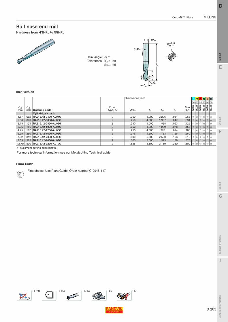
E
D 263
Mill
ing
Drilli
ng
F
Bor
ing
G
Tool
ing
Syst
ems
J
Gen
eral
Info
rmat
ion
DD
Mill
ing
CoroMill® Plura MILLING
MILLING CoroMill® Plura
Ball nose end millHardness from 43HRc to 58HRc
Inch version
Plura Guide
Helix angle: -30°Tolerances: Dc2 : h9
dmm : h6
Dimensions, inch P M K N S H
Dc2 mm
Dc2 inch Ordering code
Front type, zn dmm l2 l22 rε
Max ap1)
GC GC GC GC GC GC
1620
1620
1620
1620
1620
1620
Cylindrical shank1.57 .062 RA216.42-0430-AL04G 2 .250 4.000 2.226 .031 .063 ✩ ✩ ✩ ✩ ✩ ✩
2.36 .093 RA216.42-0630-AL06G 2 .250 4.000 1.907 .047 .094 ✩ ✩ ✩ ✩ ✩ ✩
3.18 .125 RA216.42-0830-AL03G 2 .250 4.000 1.598 .063 .125 ✩ ✩ ✩ ✩ ✩ ✩
3.96 .156 RA216.42-1030-AL04G 2 .250 4.000 1.289 .078 .156 ✩ ✩ ✩ ✩ ✩ ✩
4.75 .187 RA216.42-1230-AL05G 2 .250 4.000 .976 .094 .188 ✩ ✩ ✩ ✩ ✩ ✩
6.35 .250 RA216.42-1630-AL06G 2 .375 4.500 1.783 .125 .250 ✩ ✩ ✩ ✩ ✩ ✩
7.92 .312 RA216.42-2030-AL08G 2 .500 5.000 2.590 .156 .313 ✩ ✩ ✩ ✩ ✩ ✩
9.53 .375 RA216.42-2430-AL09G 2 .500 5.000 1.973 .188 .375 ✩ ✩ ✩ ✩ ✩ ✩
12.70 .500 RA216.42-3230-AL12G 2 .625 5.500 2.159 .250 .500 ✩ ✩ ✩ ✩ ✩ ✩
1) Maximum cutting edge length.
For more technical information, see our Metalcutting Technical guide
First choice: Use Plura Guide. Order number C-2948-117
D328 D334 D214 G6 D2
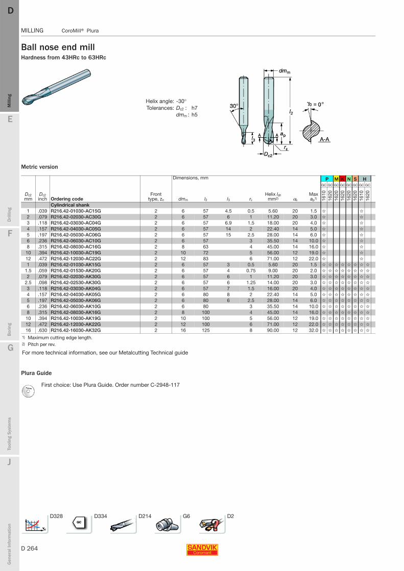
D 264
MILLING CoroMill® Plura
E
Mill
ing
Drilli
ng
F
Bor
ing
G
Tool
ing
Syst
ems
J
Gen
eral
Info
rmat
ion
DDM
illin
g
MILLING CoroMill® Plura
Ball nose end millHardness from 43HRc to 63HRc
Metric version
Plura Guide
Helix angle: -30°Tolerances: Dc2 : h7
dmm : h5
Dimensions, mm P M K N S H
Dc2 mm
Dc2 inch Ordering code
Front type, zn dmm l2 l3 rε
Helix lsh mm2) αo
Max ap1)
GC GC GC GC GC GC GC GC
1610
1620
1620
1620
1620
1620
1610
1620
Cylindrical shank1 .039 R216.42-01030-AC15G 2 6 57 4.5 0.5 5.60 20 1.5 ✩ ✩
2 .079 R216.42-02030-AC30G 2 6 57 6 1 11.20 20 3.0 ✩ ✩
3 .118 R216.42-03030-AC04G 2 6 57 6.9 1.5 18.00 20 4.0 ✩ ✩
4 .157 R216.42-04030-AC05G 2 6 57 14 2 22.40 14 5.0 ✩ ✩
5 .197 R216.42-05030-AC06G 2 6 57 15 2.5 28.00 14 6.0 ✩ ✩
6 .236 R216.42-06030-AC10G 2 6 57 3 35.50 14 10.0 ✩ ✩
8 .315 R216.42-08030-AC16G 2 8 63 4 45.00 14 16.0 ✩ ✩
10 .394 R216.42-10030-AC19G 2 10 72 5 56.00 12 19.0 ✩ ✩
12 .472 R216.42-12030-AC22G 2 12 83 6 71.00 12 22.0 ✩ ✩
1 .039 R216.42-01030-AK15G 2 6 57 3 0.5 5.60 20 1.5 ✩ ✩ ✩ ✩ ✩ ✩ ✩ ✩
1.5 .059 R216.42-01530-AK20G 2 6 57 4 0.75 9.00 20 2.0 ✩ ✩ ✩ ✩ ✩ ✩ ✩ ✩
2 .079 R216.42-02030-AK30G 2 6 57 6 1 11.20 20 3.0 ✩ ✩ ✩ ✩ ✩ ✩ ✩ ✩
2.5 .098 R216.42-02530-AK30G 2 6 57 6 1.25 14.00 20 3.0 ✩ ✩ ✩ ✩ ✩ ✩ ✩ ✩
3 .118 R216.42-03030-AK04G 2 6 57 7 1.5 16.00 20 4.0 ✩ ✩ ✩ ✩ ✩ ✩ ✩ ✩
4 .157 R216.42-04030-AK05G 2 6 80 8 2 22.40 14 5.0 ✩ ✩ ✩ ✩ ✩ ✩ ✩ ✩
5 .197 R216.42-05030-AK06G 2 6 80 6 2.5 28.00 14 6.0 ✩ ✩ ✩ ✩ ✩ ✩ ✩ ✩
6 .236 R216.42-06030-AK10G 2 6 80 3 35.50 14 10.0 ✩ ✩ ✩ ✩ ✩ ✩ ✩ ✩
8 .315 R216.42-08030-AK16G 2 8 100 4 45.00 14 16.0 ✩ ✩ ✩ ✩ ✩ ✩ ✩ ✩
10 .394 R216.42-10030-AK19G 2 10 100 5 56.00 12 19.0 ✩ ✩ ✩ ✩ ✩ ✩ ✩ ✩
12 .472 R216.42-12030-AK22G 2 12 100 6 71.00 12 22.0 ✩ ✩ ✩ ✩ ✩ ✩ ✩ ✩
16 .630 R216.42-16030-AK32G 2 16 125 8 90.00 12 32.0 ✩ ✩ ✩ ✩ ✩ ✩ ✩ ✩
1) Maximum cutting edge length.2) Pitch per rev.
For more technical information, see our Metalcutting Technical guide
First choice: Use Plura Guide. Order number C-2948-117
D328 D334 D214 G6 D2
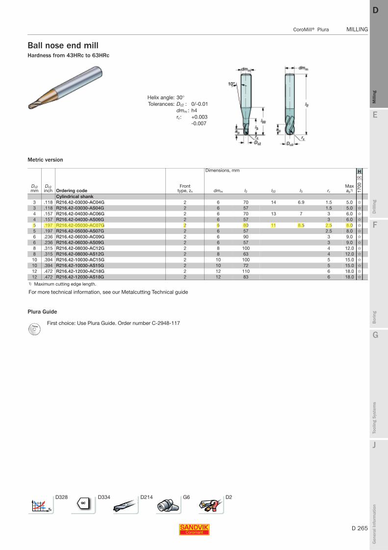
E
D 265
Mill
ing
Drilli
ng
F
Bor
ing
G
Tool
ing
Syst
ems
J
Gen
eral
Info
rmat
ion
DD
Mill
ing
CoroMill® Plura MILLING
MILLING CoroMill® Plura
Ball nose end millHardness from 43HRc to 63HRc
Metric version
Plura Guide
Helix angle: 30°Tolerances: Dc2 : 0/-0.01
dmm : h4rε: +0.003
-0.007
Dimensions, mm H
Dc2 mm
Dc2 inch Ordering code
Front type, zn dmm l2 l22 l3 rε
Max ap1)
GC
1700
Cylindrical shank3 .118 R216.42-03030-AC04G 2 6 70 14 6.9 1.5 5.0 ✩
3 .118 R216.42-03030-AS04G 2 6 57 1.5 5.0 ✩
4 .157 R216.42-04030-AC06G 2 6 70 13 7 3 6.0 ✩
4 .157 R216.42-04030-AS06G 2 6 57 3 6.0 ✩
5 .197 R216.42-05030-AC07G 2 6 80 11 8.5 2.5 8.0 ✩
5 .197 R216.42-05030-AS07G 2 6 57 2.5 8.0 ✩
6 .236 R216.42-06030-AC09G 2 6 90 3 9.0 ✩
6 .236 R216.42-06030-AS09G 2 6 57 3 9.0 ✩
8 .315 R216.42-08030-AC12G 2 8 100 4 12.0 ✩
8 .315 R216.42-08030-AS12G 2 8 63 4 12.0 ✩
10 .394 R216.42-10030-AC15G 2 10 100 5 15.0 ✩
10 .394 R216.42-10030-AS15G 2 10 72 5 15.0 ✩
12 .472 R216.42-12030-AC18G 2 12 110 6 18.0 ✩
12 .472 R216.42-12030-AS18G 2 12 83 6 18.0 ✩
1) Maximum cutting edge length.
For more technical information, see our Metalcutting Technical guide
First choice: Use Plura Guide. Order number C-2948-117
D328 D334 D214 G6 D2
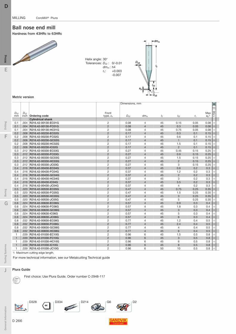
D 266
MILLING CoroMill® Plura
E
Mill
ing
Drilli
ng
F
Bor
ing
G
Tool
ing
Syst
ems
J
Gen
eral
Info
rmat
ion
DDM
illin
g
MILLING CoroMill® Plura
Ball nose end millHardness from 43HRc to 63HRc
Metric version
Plura Guide
Helix angle: 30°Tolerances: Dc2 : 0/-0.01
dmm : h4rε: +0.003
-0.007
Dimensions, mm H
Dc2 mm
Dc2 inch Ordering code
Front type, zn Dc3 dmm l2 l22 rε
Max ap1)
GC
1700
Cylindrical shank0.1 .004 R216.42-00130-EC01G 2 0.08 4 45 0.15 0.05 0.08 ✩
0.1 .004 R216.42-00130-FC01G 2 0.08 4 45 0.3 0.05 0.08 ✩
0.1 .004 R216.42-00130-HC01G 2 0.08 4 45 0.75 0.05 0.08 ✩
0.2 .008 R216.42-00230-EC02G 2 0.17 4 45 0.3 0.1 0.15 ✩
0.2 .008 R216.42-00230-FC02G 2 0.17 4 45 0.6 0.1 0.15 ✩
0.2 .008 R216.42-00230-GC02G 2 0.17 4 45 1 0.1 0.15 ✩
0.2 .008 R216.42-00230-HC02G 2 0.17 4 45 1.5 0.1 0.15 ✩
0.2 .008 R216.42-00230-IC02G 2 0.17 4 45 2 0.1 0.15 ✩
0.3 .012 R216.42-00330-EC03G 2 0.27 4 45 0.45 0.15 0.25 ✩
0.3 .012 R216.42-00330-FC03G 2 0.27 4 45 0.9 0.15 0.25 ✩
0.3 .012 R216.42-00330-GC03G 2 0.27 4 45 1.5 0.15 0.25 ✩
0.3 .012 R216.42-00330-HC03G 2 0.27 4 45 2 0.15 0.25 ✩
0.3 .012 R216.42-00330-JC03G 2 0.27 4 45 3 0.15 0.25 ✩
0.4 .016 R216.42-00430-EC04G 2 0.37 4 45 0.6 0.2 0.3 ✩
0.4 .016 R216.42-00430-FC04G 2 0.37 4 45 1.2 0.2 0.3 ✩
0.4 .016 R216.42-00430-GC04G 2 0.37 4 45 2 0.2 0.3 ✩
0.4 .016 R216.42-00430-HC04G 2 0.37 4 45 3 0.2 0.3 ✩
0.4 .016 R216.42-00430-IC04G 2 0.37 4 45 3.5 0.2 0.3 ✩
0.4 .016 R216.42-00430-JC04G 2 0.37 4 45 4 0.2 0.3 ✩
0.5 .020 R216.42-00530-EC05G 2 0.47 4 45 0.75 0.25 0.35 ✩
0.5 .020 R216.42-00530-FC05G 2 0.47 4 45 1.5 0.25 0.35 ✩
0.5 .020 R216.42-00530-HC05G 2 0.47 4 45 3 0.25 0.35 ✩
0.5 .020 R216.42-00530-JC05G 2 0.47 4 45 5 0.25 0.35 ✩
0.6 .024 R216.42-00630-EC06G 2 0.57 4 45 0.9 0.3 0.4 ✩
0.6 .024 R216.42-00630-FC06G 2 0.57 4 45 1.8 0.3 0.4 ✩
0.6 .024 R216.42-00630-GC06G 2 0.57 4 45 3 0.3 0.4 ✩
0.6 .024 R216.42-00630-IC06G 2 0.57 4 45 5 0.3 0.4 ✩
0.6 .024 R216.42-00630-JC06G 2 0.57 4 45 6 0.3 0.4 ✩
0.8 .032 R216.42-00830-EC08G 2 0.77 4 45 1.2 0.4 0.5 ✩
0.8 .032 R216.42-00830-FC08G 2 0.77 4 45 2.4 0.4 0.5 ✩
0.8 .032 R216.42-00830-GC08G 2 0.77 4 45 4 0.4 0.5 ✩
0.8 .032 R216.42-00830-HC08G 2 0.77 4 45 6 0.4 0.5 ✩
1 .039 R216.42-01030-EC10G 2 0.96 6 45 1.5 0.5 0.8 ✩
1 .039 R216.42-01030-FC10G 2 0.96 6 45 3 0.5 0.8 ✩
1 .039 R216.42-01030-HC10G 2 0.96 6 45 6 0.5 0.8 ✩
1 .039 R216.42-01030-IC10G 2 0.96 6 45 8 0.5 0.8 ✩
1 .039 R216.42-01030-JC10G 2 0.96 6 50 10 0.5 0.8 ✩
1) Maximum cutting edge length.
For more technical information, see our Metalcutting Technical guide
First choice: Use Plura Guide. Order number C-2948-117
D328 D334 D214 G6 D2
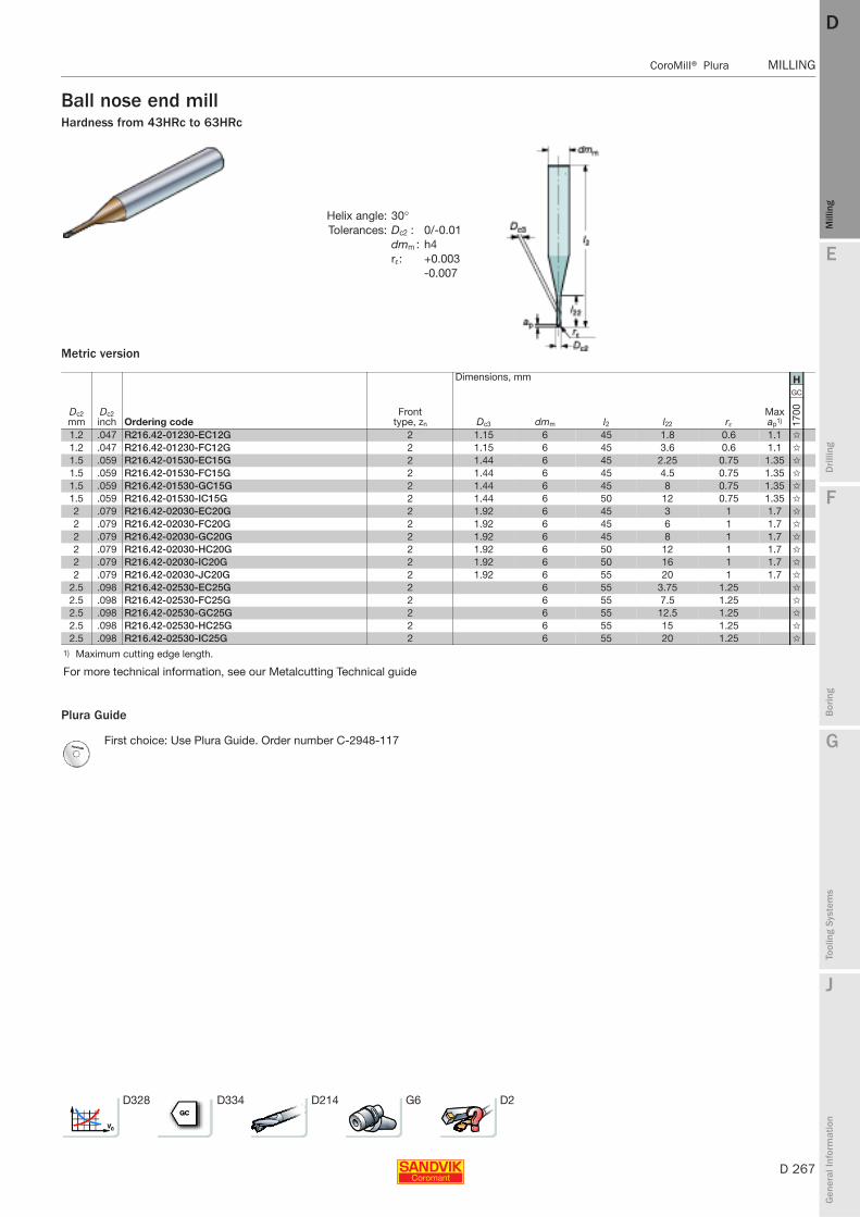
E
D 267
Mill
ing
Drilli
ng
F
Bor
ing
G
Tool
ing
Syst
ems
J
Gen
eral
Info
rmat
ion
DD
Mill
ing
CoroMill® Plura MILLING
MILLING CoroMill® Plura
Ball nose end millHardness from 43HRc to 63HRc
Metric version
Plura Guide
Helix angle: 30°Tolerances: Dc2 : 0/-0.01
dmm : h4rε: +0.003
-0.007
Dimensions, mm H
Dc2 mm
Dc2 inch Ordering code
Front type, zn Dc3 dmm l2 l22 rε
Max ap1)
GC
1700
1.2 .047 R216.42-01230-EC12G 2 1.15 6 45 1.8 0.6 1.1 ✩
1.2 .047 R216.42-01230-FC12G 2 1.15 6 45 3.6 0.6 1.1 ✩
1.5 .059 R216.42-01530-EC15G 2 1.44 6 45 2.25 0.75 1.35 ✩
1.5 .059 R216.42-01530-FC15G 2 1.44 6 45 4.5 0.75 1.35 ✩
1.5 .059 R216.42-01530-GC15G 2 1.44 6 45 8 0.75 1.35 ✩
1.5 .059 R216.42-01530-IC15G 2 1.44 6 50 12 0.75 1.35 ✩
2 .079 R216.42-02030-EC20G 2 1.92 6 45 3 1 1.7 ✩
2 .079 R216.42-02030-FC20G 2 1.92 6 45 6 1 1.7 ✩
2 .079 R216.42-02030-GC20G 2 1.92 6 45 8 1 1.7 ✩
2 .079 R216.42-02030-HC20G 2 1.92 6 50 12 1 1.7 ✩
2 .079 R216.42-02030-IC20G 2 1.92 6 50 16 1 1.7 ✩
2 .079 R216.42-02030-JC20G 2 1.92 6 55 20 1 1.7 ✩
2.5 .098 R216.42-02530-EC25G 2 6 55 3.75 1.25 ✩
2.5 .098 R216.42-02530-FC25G 2 6 55 7.5 1.25 ✩
2.5 .098 R216.42-02530-GC25G 2 6 55 12.5 1.25 ✩
2.5 .098 R216.42-02530-HC25G 2 6 55 15 1.25 ✩
2.5 .098 R216.42-02530-IC25G 2 6 55 20 1.25 ✩
1) Maximum cutting edge length.
For more technical information, see our Metalcutting Technical guide
First choice: Use Plura Guide. Order number C-2948-117
D328 D334 D214 G6 D2
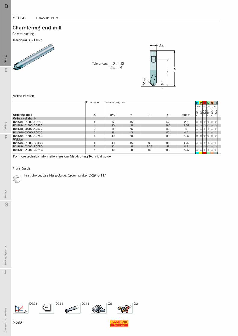
D 268
MILLING CoroMill® Plura
E
Mill
ing
Drilli
ng
F
Bor
ing
G
Tool
ing
Syst
ems
J
Gen
eral
Info
rmat
ion
DDM
illin
g
MILLING CoroMill® Plura
Chamfering end millCentre cutting
Metric version
Plura Guide
Hardness <63 HRc
Tolerances: Dc : h10dmm : h6
Front type Dimensions, mm P M K N S H
Ordering code zn dmm κr l1 l2 Max ap
GC GC GC GC GC GC
1620
1620
1620
1620
1620
1620
Cylindrical shankR215.84-01000-AC25G 4 6 45 57 2.5 ✩ ✩ ✩ ✩ ✩ ✩
R215.84-01500-AC43G 4 10 45 100 4.25 ✩ ✩ ✩ ✩ ✩ ✩
R215.85-02000-AC30G 5 8 45 80 3 ✩ ✩ ✩ ✩ ✩ ✩
R215.86-03000-AC05G 6 12 45 83 4.5 ✩ ✩ ✩ ✩ ✩ ✩
R215.94-01500-AC74G 4 10 60 100 7.35 ✩ ✩ ✩ ✩ ✩ ✩
WeldonR215.84-01500-BC43G 4 10 45 80 100 4.25 ✩ ✩ ✩ ✩ ✩ ✩
R215.86-03000-BC05G 6 12 45 60.5 83 4.5 ✩ ✩ ✩ ✩ ✩ ✩
R215.94-01500-BC74G 4 10 60 80 100 7.35 ✩ ✩ ✩ ✩ ✩ ✩
For more technical information, see our Metalcutting Technical guide
First choice: Use Plura Guide. Order number C-2948-117
D328 D334 D214 G6 D2

E
D 269
Mill
ing
Drilli
ng
F
Bor
ing
G
Tool
ing
Syst
ems
J
Gen
eral
Info
rmat
ion
DD
Mill
ing
CoroMill® Plura MILLING
MILLING CoroMill® Plura
Chamfering radius end millHardness <63HRc
Metric version
Plura Guide
Tolerances: dmm : h6
Dimensions, mm P M K N S H
Dc mm
Dc inch Ordering code
Front type, zn dmm l2 rε
Max ap1)
GC GC GC GC GC GC
1620
1620
1620
1620
1620
1620
Cylindrical shank4 .157 R215.03-04000BAC01G 3 6 57 0.5 0.5 ✩ ✩ ✩ ✩ ✩ ✩
4 .157 R215.03-04000CAC01G 3 6 57 0.75 0.8 ✩ ✩ ✩ ✩ ✩ ✩
4 .157 R215.04-04000CAC01G 4 8 63 1 1.0 ✩ ✩ ✩ ✩ ✩ ✩
4 .157 R215.04-04000DAC02G 4 8 63 1.5 1.5 ✩ ✩ ✩ ✩ ✩ ✩
5 .197 R215.04-05000EAC02G 4 10 72 2 2.0 ✩ ✩ ✩ ✩ ✩ ✩
5 .197 R215.04-05000FAC03G 4 10 72 2.5 2.5 ✩ ✩ ✩ ✩ ✩ ✩
5 .197 R215.04-05000GAC03G 4 12 83 3 3.0 ✩ ✩ ✩ ✩ ✩ ✩
6 .236 R215.04-06000IAC04G 4 14 83 4 4.0 ✩ ✩ ✩ ✩ ✩ ✩
6 .236 R215.04-06000KAC05G 4 16 92 5 5.0 ✩ ✩ ✩ ✩ ✩ ✩
8 .315 R215.04-08000MAC06G 4 20 104 6 6.0 ✩ ✩ ✩ ✩ ✩ ✩
1) Maximum cutting edge length.
For more technical information, see our Metalcutting Technical guide
First choice: Use Plura Guide. Order number C-2948-117
D328 D334 D214 G6 D2
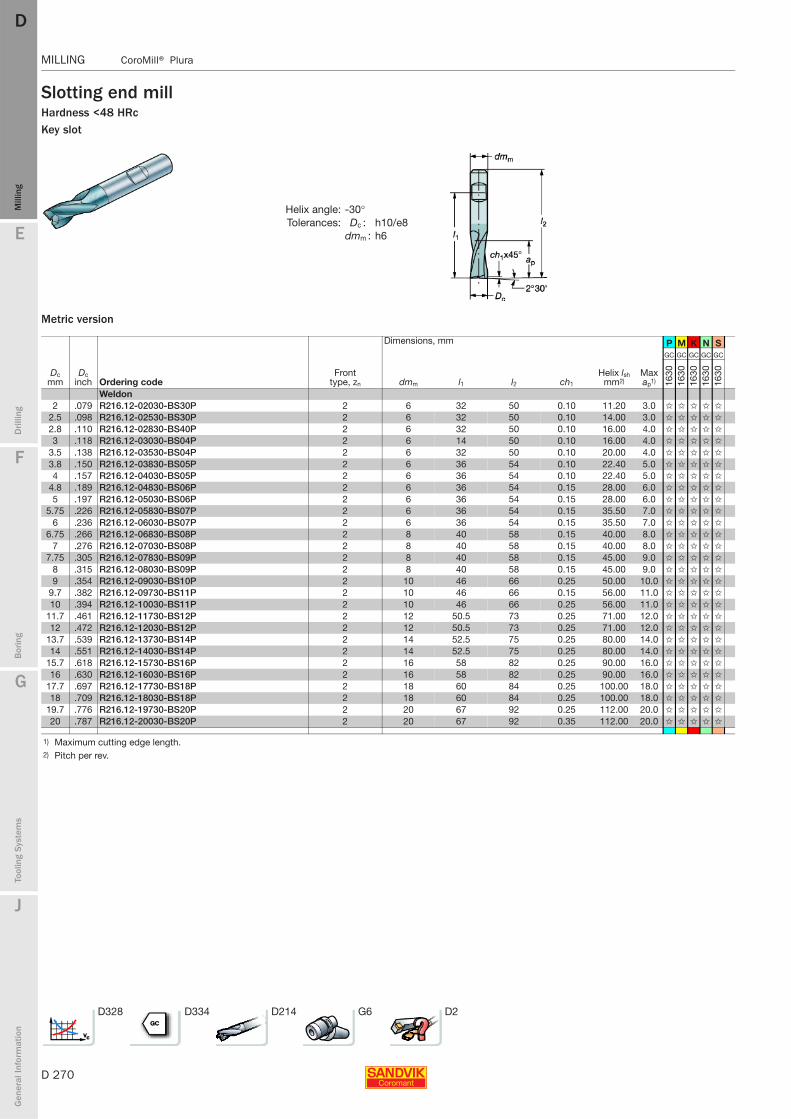
D 270
MILLING CoroMill® Plura
E
Mill
ing
Drilli
ng
F
Bor
ing
G
Tool
ing
Syst
ems
J
Gen
eral
Info
rmat
ion
DDM
illin
g
MILLING CoroMill® Plura
Slotting end millHardness <48 HRcKey slot
Metric version
Helix angle: -30°Tolerances: Dc : h10/e8
dmm : h6
Dimensions, mm P M K N S
Dc mm
Dc inch Ordering code
Front type, zn dmm l1 l2 ch1
Helix lsh mm2)
Max ap1)
GC GC GC GC GC
1630
1630
1630
1630
1630
Weldon2 .079 R216.12-02030-BS30P 2 6 32 50 0.10 11.20 3.0 ✩ ✩ ✩ ✩ ✩
2.5 .098 R216.12-02530-BS30P 2 6 32 50 0.10 14.00 3.0 ✩ ✩ ✩ ✩ ✩
2.8 .110 R216.12-02830-BS40P 2 6 32 50 0.10 16.00 4.0 ✩ ✩ ✩ ✩ ✩
3 .118 R216.12-03030-BS04P 2 6 14 50 0.10 16.00 4.0 ✩ ✩ ✩ ✩ ✩
3.5 .138 R216.12-03530-BS04P 2 6 32 50 0.10 20.00 4.0 ✩ ✩ ✩ ✩ ✩
3.8 .150 R216.12-03830-BS05P 2 6 36 54 0.10 22.40 5.0 ✩ ✩ ✩ ✩ ✩
4 .157 R216.12-04030-BS05P 2 6 36 54 0.10 22.40 5.0 ✩ ✩ ✩ ✩ ✩
4.8 .189 R216.12-04830-BS06P 2 6 36 54 0.15 28.00 6.0 ✩ ✩ ✩ ✩ ✩
5 .197 R216.12-05030-BS06P 2 6 36 54 0.15 28.00 6.0 ✩ ✩ ✩ ✩ ✩
5.75 .226 R216.12-05830-BS07P 2 6 36 54 0.15 35.50 7.0 ✩ ✩ ✩ ✩ ✩
6 .236 R216.12-06030-BS07P 2 6 36 54 0.15 35.50 7.0 ✩ ✩ ✩ ✩ ✩
6.75 .266 R216.12-06830-BS08P 2 8 40 58 0.15 40.00 8.0 ✩ ✩ ✩ ✩ ✩
7 .276 R216.12-07030-BS08P 2 8 40 58 0.15 40.00 8.0 ✩ ✩ ✩ ✩ ✩
7.75 .305 R216.12-07830-BS09P 2 8 40 58 0.15 45.00 9.0 ✩ ✩ ✩ ✩ ✩
8 .315 R216.12-08030-BS09P 2 8 40 58 0.15 45.00 9.0 ✩ ✩ ✩ ✩ ✩
9 .354 R216.12-09030-BS10P 2 10 46 66 0.25 50.00 10.0 ✩ ✩ ✩ ✩ ✩
9.7 .382 R216.12-09730-BS11P 2 10 46 66 0.15 56.00 11.0 ✩ ✩ ✩ ✩ ✩
10 .394 R216.12-10030-BS11P 2 10 46 66 0.25 56.00 11.0 ✩ ✩ ✩ ✩ ✩
11.7 .461 R216.12-11730-BS12P 2 12 50.5 73 0.25 71.00 12.0 ✩ ✩ ✩ ✩ ✩
12 .472 R216.12-12030-BS12P 2 12 50.5 73 0.25 71.00 12.0 ✩ ✩ ✩ ✩ ✩
13.7 .539 R216.12-13730-BS14P 2 14 52.5 75 0.25 80.00 14.0 ✩ ✩ ✩ ✩ ✩
14 .551 R216.12-14030-BS14P 2 14 52.5 75 0.25 80.00 14.0 ✩ ✩ ✩ ✩ ✩
15.7 .618 R216.12-15730-BS16P 2 16 58 82 0.25 90.00 16.0 ✩ ✩ ✩ ✩ ✩
16 .630 R216.12-16030-BS16P 2 16 58 82 0.25 90.00 16.0 ✩ ✩ ✩ ✩ ✩
17.7 .697 R216.12-17730-BS18P 2 18 60 84 0.25 100.00 18.0 ✩ ✩ ✩ ✩ ✩
18 .709 R216.12-18030-BS18P 2 18 60 84 0.25 100.00 18.0 ✩ ✩ ✩ ✩ ✩
19.7 .776 R216.12-19730-BS20P 2 20 67 92 0.25 112.00 20.0 ✩ ✩ ✩ ✩ ✩
20 .787 R216.12-20030-BS20P 2 20 67 92 0.35 112.00 20.0 ✩ ✩ ✩ ✩ ✩
1) Maximum cutting edge length.2) Pitch per rev.
D328 D334 D214 G6 D2
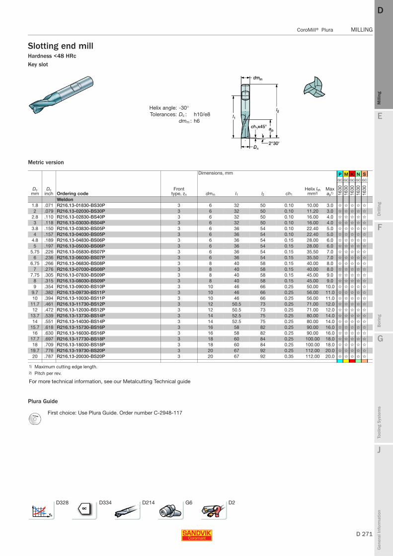
E
D 271
Mill
ing
Drilli
ng
F
Bor
ing
G
Tool
ing
Syst
ems
J
Gen
eral
Info
rmat
ion
DD
Mill
ing
CoroMill® Plura MILLING
MILLING CoroMill® Plura
Slotting end millHardness <48 HRcKey slot
Metric version
Plura Guide
Helix angle: -30°Tolerances: Dc : h10/e8
dmm : h6
Dimensions, mm P M K N S
Dc mm
Dc inch Ordering code
Front type, zn dmm l1 l2 ch1
Helix lsh mm2)
Max ap1)
GC GC GC GC GC
1630
1630
1630
1630
1630
Weldon1.8 .071 R216.13-01830-BS30P 3 6 32 50 0.10 10.00 3.0 ✩ ✩ ✩ ✩ ✩
2 .079 R216.13-02030-BS30P 3 6 32 50 0.10 11.20 3.0 ✩ ✩ ✩ ✩ ✩
2.8 .110 R216.13-02830-BS40P 3 6 32 50 0.10 16.00 4.0 ✩ ✩ ✩ ✩ ✩
3 .118 R216.13-03030-BS04P 3 6 32 50 0.10 16.00 4.0 ✩ ✩ ✩ ✩ ✩
3.8 .150 R216.13-03830-BS05P 3 6 36 54 0.10 22.40 5.0 ✩ ✩ ✩ ✩ ✩
4 .157 R216.13-04030-BS05P 3 6 36 54 0.10 22.40 5.0 ✩ ✩ ✩ ✩ ✩
4.8 .189 R216.13-04830-BS06P 3 6 36 54 0.15 28.00 6.0 ✩ ✩ ✩ ✩ ✩
5 .197 R216.13-05030-BS06P 3 6 36 54 0.15 28.00 6.0 ✩ ✩ ✩ ✩ ✩
5.75 .226 R216.13-05830-BS07P 3 6 36 54 0.15 35.50 7.0 ✩ ✩ ✩ ✩ ✩
6 .236 R216.13-06030-BS07P 3 6 36 54 0.15 35.50 7.0 ✩ ✩ ✩ ✩ ✩
6.75 .266 R216.13-06830-BS08P 3 8 40 58 0.15 40.00 8.0 ✩ ✩ ✩ ✩ ✩
7 .276 R216.13-07030-BS08P 3 8 40 58 0.15 40.00 8.0 ✩ ✩ ✩ ✩ ✩
7.75 .305 R216.13-07830-BS09P 3 8 40 58 0.15 45.00 9.0 ✩ ✩ ✩ ✩ ✩
8 .315 R216.13-08030-BS09P 3 8 40 58 0.15 45.00 9.0 ✩ ✩ ✩ ✩ ✩
9 .354 R216.13-09030-BS10P 3 10 46 66 0.25 50.00 10.0 ✩ ✩ ✩ ✩ ✩
9.7 .382 R216.13-09730-BS11P 3 10 46 66 0.25 56.00 11.0 ✩ ✩ ✩ ✩ ✩
10 .394 R216.13-10030-BS11P 3 10 46 66 0.25 56.00 11.0 ✩ ✩ ✩ ✩ ✩
11.7 .461 R216.13-11730-BS12P 3 12 50.5 73 0.25 71.00 12.0 ✩ ✩ ✩ ✩ ✩
12 .472 R216.13-12030-BS12P 3 12 50.5 73 0.25 71.00 12.0 ✩ ✩ ✩ ✩ ✩
13.7 .539 R216.13-13730-BS14P 3 14 52.5 75 0.25 80.00 14.0 ✩ ✩ ✩ ✩ ✩
14 .551 R216.13-14030-BS14P 3 14 52.5 75 0.25 80.00 14.0 ✩ ✩ ✩ ✩ ✩
15.7 .618 R216.13-15730-BS16P 3 16 58 82 0.25 90.00 16.0 ✩ ✩ ✩ ✩ ✩
16 .630 R216.13-16030-BS16P 3 16 58 82 0.25 90.00 16.0 ✩ ✩ ✩ ✩ ✩
17.7 .697 R216.13-17730-BS18P 3 18 60 84 0.25 100.00 18.0 ✩ ✩ ✩ ✩ ✩
18 .709 R216.13-18030-BS18P 3 18 60 84 0.25 100.00 18.0 ✩ ✩ ✩ ✩ ✩
19.7 .776 R216.13-19730-BS20P 3 20 67 92 0.25 112.00 20.0 ✩ ✩ ✩ ✩ ✩
20 .787 R216.13-20030-BS20P 3 20 67 92 0.35 112.00 20.0 ✩ ✩ ✩ ✩ ✩
1) Maximum cutting edge length.2) Pitch per rev.
For more technical information, see our Metalcutting Technical guide
First choice: Use Plura Guide. Order number C-2948-117
D328 D334 D214 G6 D2
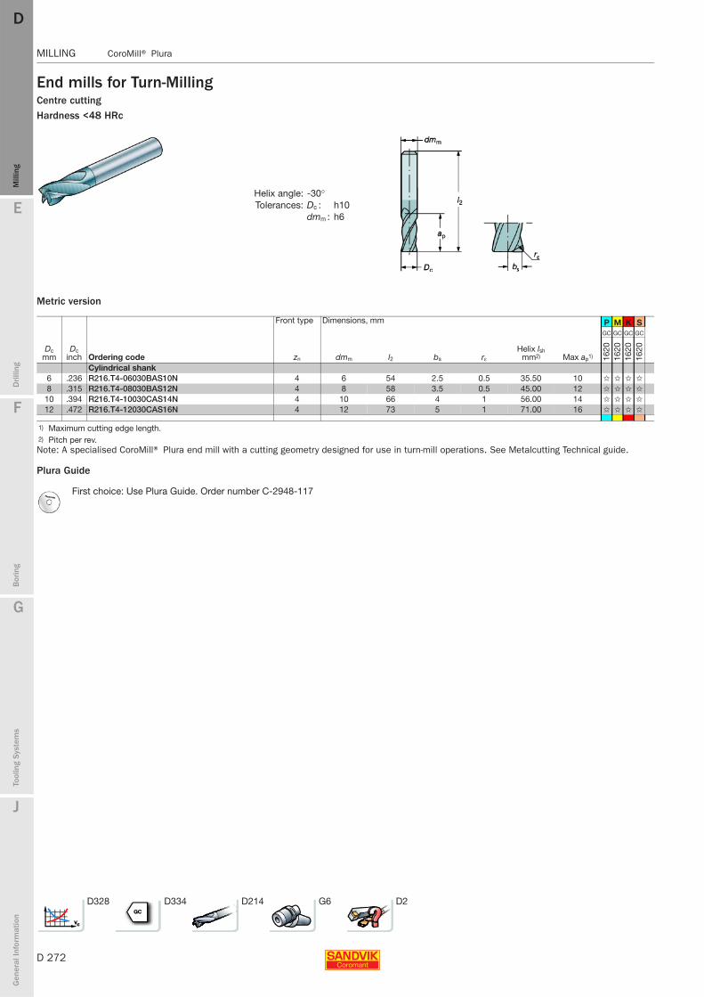
D 272
MILLING CoroMill® Plura
E
Mill
ing
Drilli
ng
F
Bor
ing
G
Tool
ing
Syst
ems
J
Gen
eral
Info
rmat
ion
DDM
illin
g
MILLING CoroMill® Plura
End mills for Turn-MillingCentre cuttingHardness <48 HRc
Metric version
Note: A specialised CoroMill® Plura end mill with a cutting geometry designed for use in turn-mill operations. See Metalcutting Technical guide.
Plura Guide
Helix angle: -30°Tolerances: Dc : h10
dmm : h6
Front type Dimensions, mm P M K S
Dc mm
Dc inch Ordering code zn dmm l2 bs rε
Helix lsh mm2) Max ap1)
GC GC GC GC
1620
1620
1620
1620
Cylindrical shank6 .236 R216.T4-06030BAS10N 4 6 54 2.5 0.5 35.50 10 ✩ ✩ ✩ ✩
8 .315 R216.T4-08030BAS12N 4 8 58 3.5 0.5 45.00 12 ✩ ✩ ✩ ✩
10 .394 R216.T4-10030CAS14N 4 10 66 4 1 56.00 14 ✩ ✩ ✩ ✩
12 .472 R216.T4-12030CAS16N 4 12 73 5 1 71.00 16 ✩ ✩ ✩ ✩
1) Maximum cutting edge length.2) Pitch per rev.
First choice: Use Plura Guide. Order number C-2948-117
D328 D334 D214 G6 D2
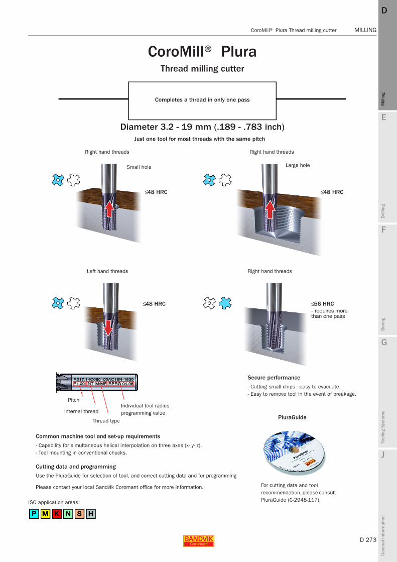
E
D 273
Mill
ing
Drilli
ng
F
Bor
ing
G
Tool
ing
Syst
ems
J
Gen
eral
Info
rmat
ion
DD
Mill
ing
CoroMill® Plura Thread milling cutter MILLING
MILLING CoroMill® Plura Thread milling cutter
CoroMill® PluraThread milling cutter
Completes a thread in only one pass
Diameter 3.2 - 19 mm (.189 - .783 inch)Just one tool for most threads with the same pitch
Right hand threads
Small hole
≤ 48 HRC
Left hand threads
≤ 48 HRC
Pitch
Internal thread
Thread type
Individual tool radius programming value
Common machine tool and set-up requirements
- Capability for simultaneous helical interpolation on three axes (x- y- z).- Tool mounting in conventional chucks.
Cutting data and programming
Use the PluraGuide for selection of tool, and correct cutting data and for programming
Please contact your local Sandvik Coromant office for more information.
ISO application areas:
Right hand threads
Large hole
≤ 48 HRC
Right hand threads
≤56 HRC- requires more than one pass
Secure performance
- Cutting small chips - easy to evacuate.- Easy to remove tool in the event of breakage.
PluraGuide
For cutting data and tool recommendation, please consult PluraGuide (C-2948-117).
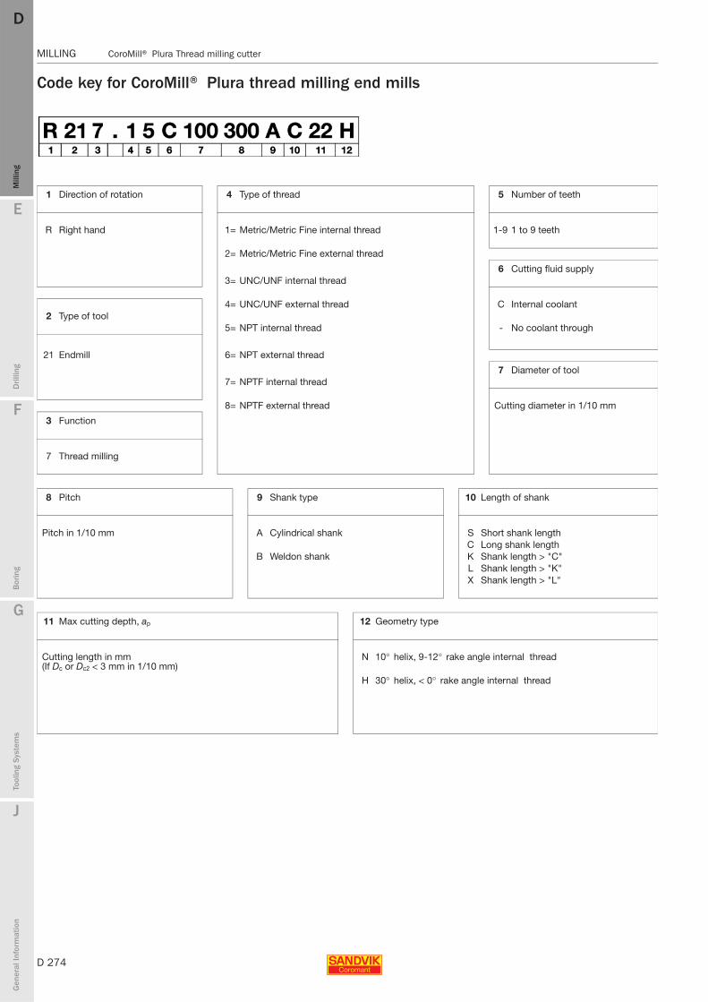
D 274
MILLING CoroMill® Plura Thread milling cutter
E
Mill
ing
Drilli
ng
F
Bor
ing
G
Tool
ing
Syst
ems
J
Gen
eral
Info
rmat
ion
DDM
illin
g
MILLING CoroMill® Plura Thread milling cutter
Code key for CoroMill® Plura thread milling end mills
1 Direction of rotation 4 Type of thread 5 Number of teeth
R Right hand 1= Metric/Metric Fine internal thread 1-9 1 to 9 teeth
2= Metric/Metric Fine external thread
6 Cutting fluid supply3= UNC/UNF internal thread
4= UNC/UNF external thread C Internal coolant2 Type of tool
5= NPT internal thread - No coolant through
21 Endmill 6= NPT external thread
7 Diameter of tool7= NPTF internal thread
8= NPTF external thread Cutting diameter in 1/10 mm
3 Function
7 Thread milling
8 Pitch 9 Shank type 10 Length of shank
Pitch in 1/10 mm A Cylindrical shank S Short shank lengthC Long shank length
B Weldon shank K Shank length > "C"L Shank length > "K"X Shank length > "L"
11 Max cutting depth, ap 12 Geometry type
Cutting length in mm (If Dc or Dc2 < 3 mm in 1/10 mm)
N 10° helix, 9-12° rake angle internal thread
H 30° helix, < 0° rake angle internal thread

E
D 275
Mill
ing
Drilli
ng
F
Bor
ing
G
Tool
ing
Syst
ems
J
Gen
eral
Info
rmat
ion
DD
Mill
ing
CoroMill® Plura Thread milling cutter MILLING
MILLING CoroMill® Plura Thread milling cutter
CoroMill® Plura Thread milling cutterInternal threadsInch, 60°
Hardness <48HRc
Front type Dimensions, inch P M K N S
Ordering code Thread Coolant1) zn Pitch Pth2) Dc dmm l1 l2 Max ap
GC GC GC GC GC
1630
1630
1630
1630
1630
Cylindrical shankR217.53-079270AC11N 1/8-27 NPT 0 3 27 .311 .315 .866 2.284 .453 ✩ ✩ ✩ ✩ ✩
R217.53-099180AC15N 1/4-18 NPT 0 3 18 .390 .394 1.024 2.598 .627 ✩ ✩ ✩ ✩ ✩
R217.54-159140AC20N 1/2-14 NPT 0 4 14 .626 .630 1.339 3.228 .806 ✩ ✩ ✩ ✩ ✩
R217.55-199115AC27N 1/2-14 NPT 0 5 11.5 .784 .787 1.654 3.622 1.068 ✩ ✩ ✩ ✩ ✩
R217.73-079270AC11N 1/8-27 NPTF 0 3 27 .311 .315 .866 2.284 .453 ✩ ✩ ✩ ✩ ✩
R217.73-099180AC15N 1/4-18 NPTF 0 3 18 .390 .394 1.024 2.598 .627 ✩ ✩ ✩ ✩ ✩
R217.74-159140AC20N 1/2-14 NPTF 0 4 14 .626 .630 1.339 3.228 .806 ✩ ✩ ✩ ✩ ✩
R217.75-199115AC27N 1/2-14 NPTF 0 5 11.5 .784 .787 1.654 3.622 1.068 ✩ ✩ ✩ ✩ ✩
R217.33C048200AC13N 1/4-20 UNC 1 3 20 .189 .236 .827 2.244 .551 ✩ ✩ ✩ ✩ ✩
R217.33C048280AC13N 1/4-28 UNF 1 3 28 .189 .236 .827 2.244 .536 ✩ ✩ ✩ ✩ ✩
R217.33C055180AC14N 5/16-18 UNC 1 3 18 .216 .236 .827 2.244 .556 ✩ ✩ ✩ ✩ ✩
R217.33C060240AC13N 5/16-24 UNF 1 3 24 .236 .236 .827 2.244 .541 ✩ ✩ ✩ ✩ ✩
R217.34C075160AC19N 3/8-16 UNC 1 4 16 .295 .315 1.063 2.480 .750 ✩ ✩ ✩ ✩ ✩
R217.34C080140AC19N 7/16-14 UNC 1 4 14 .315 .315 1.063 2.480 .785 ✩ ✩ ✩ ✩ ✩
R217.34C080200AC19N 7/16-20 UNF 1 4 20 .315 .315 1.063 2.480 .750 ✩ ✩ ✩ ✩ ✩
R217.34C100120AC21N 9/16-12 UNC 1 4 12 .394 .394 1.260 2.835 .833 ✩ ✩ ✩ ✩ ✩
R217.34C100130AC21N 1/2-13 UNC 1 4 13 .394 .394 1.260 2.835 .846 ✩ ✩ ✩ ✩ ✩
R217.34C100180AC22N 9/16-18 UNF 1 4 18 .394 .394 1.260 2.835 .889 ✩ ✩ ✩ ✩ ✩
R217.34C120110AC25N 5/8-11 UNC 1 4 11 .472 .472 1.496 3.268 1.000 ✩ ✩ ✩ ✩ ✩
R217.35C140100AC33N 3/4-10 UNC 1 5 10 .551 .551 1.496 3.268 1.300 ✩ ✩ ✩ ✩ ✩
R217.35C140160AC31N 3/4-16 UNF 1 5 16 .551 .551 1.496 3.268 1.250 ✩ ✩ ✩ ✩ ✩
1) 0 = no coolant, 1 = coolant through centre, 6 = coolant through flange, 7 = coolant through centre and through flange2) Pitch numbers are given per inch (TPI).
D333 D334 D214 G6 D2

D 276
MILLING CoroMill® Plura Thread milling cutter
E
Mill
ing
Drilli
ng
F
Bor
ing
G
Tool
ing
Syst
ems
J
Gen
eral
Info
rmat
ion
DDM
illin
g
MILLING CoroMill® Plura Thread milling cutter
CoroMill® Plura Thread milling cutterInternal threadsMetric/Metric Fine, 60°
Hardness <48HRc
Front type Dimensions, mm P M K N S
Thread type Ordering code Coolant1) zn Pitch Pth Dc dmm l1 l2 Max ap
GC GC GC GC GC
1630
1630
1630
1630
1630
Cylindrical shankM4x0.7 R217.13-032070AC08N 0 3 0.7 3.2 6 21 57 8.4 ✩ ✩ ✩ ✩ ✩
M5x0.8 R217.13-041080AC11N 0 3 0.8 4.1 6 21 57 11.2 ✩ ✩ ✩ ✩ ✩
M6x0.5 R217.13C048050AC10N 1 3 0.5 4.8 6 21 57 10 ✩ ✩ ✩ ✩ ✩
M6x1.0 R217.14C045100AC13N 1 4 1 4.5 6 21 57 13 ✩ ✩ ✩ ✩ ✩
M8x0.75 R217.13C060075AC12N 1 3 0.75 6 6 21 57 12 ✩ ✩ ✩ ✩ ✩
M8x1.25 R217.14C060125AK17N 1 4 1.25 6 6 29 65 17.5 ✩ ✩ ✩ ✩ ✩
M10x1.0 R217.14C080100AC16N 1 4 1 8 8 27 63 16 ✩ ✩ ✩ ✩ ✩
M10x1.5 R217.14C075150AK21N 1 4 1.5 7.5 8 36 72 21 ✩ ✩ ✩ ✩ ✩
M12x1.75 R217.14C095175AK26N 1 4 1.75 9.5 10 40 80 26.25 ✩ ✩ ✩ ✩ ✩
M14x1.5 R217.14C120150AC22N 1 4 1.5 12 12 38 83 22.5 ✩ ✩ ✩ ✩ ✩
M14x2.0 R217.15C100200AK30N 1 5 2 10 10 43 83 30 ✩ ✩ ✩ ✩ ✩
M16x2.0 R217.15C120200AK34N 1 5 2 12 12 47 92 34 ✩ ✩ ✩ ✩ ✩
M18x1.5 R217.15C160150AC30N 1 5 1.5 16 16 44 92 30 ✩ ✩ ✩ ✩ ✩
M20x2.5 R217.15C160250AK42N 1 5 2.5 16 16 57 105 42.5 ✩ ✩ ✩ ✩ ✩
M24x3.0 R217.15C190300AK50N 1 5 3 19 20 75 125 50 ✩ ✩ ✩ ✩ ✩
1) 0 = no coolant, 1 = coolant through centre, 6 = coolant through flange, 7 = coolant through centre and through flange
D333 D334 D214 G6 D2
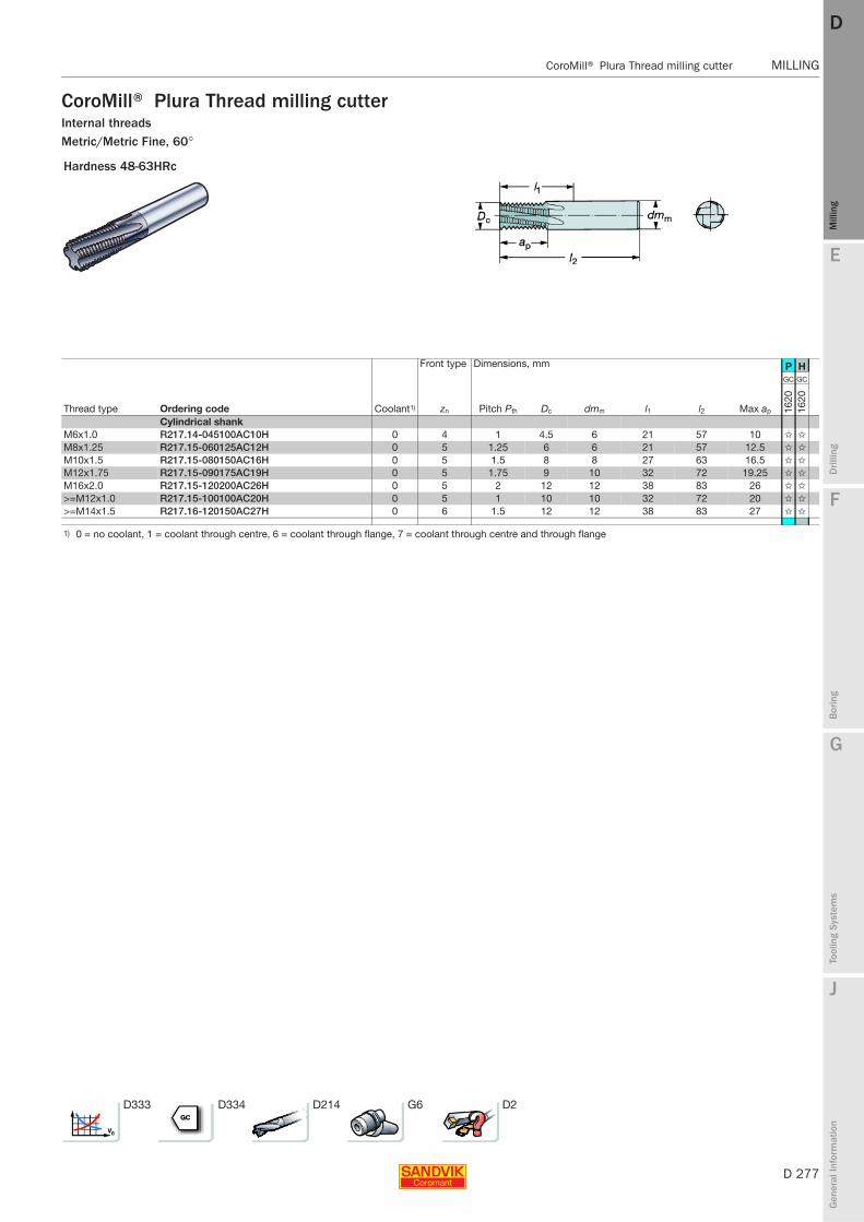
E
D 277
Mill
ing
Drilli
ng
F
Bor
ing
G
Tool
ing
Syst
ems
J
Gen
eral
Info
rmat
ion
DD
Mill
ing
CoroMill® Plura Thread milling cutter MILLING
MILLING CoroMill® Plura Thread milling cutter
CoroMill® Plura Thread milling cutterInternal threadsMetric/Metric Fine, 60°
Hardness 48-63HRc
Front type Dimensions, mm P H
Thread type Ordering code Coolant1) zn Pitch Pth Dc dmm l1 l2 Max ap
GC GC
1620
1620
Cylindrical shankM6x1.0 R217.14-045100AC10H 0 4 1 4.5 6 21 57 10 ✩ ✩
M8x1.25 R217.15-060125AC12H 0 5 1.25 6 6 21 57 12.5 ✩ ✩
M10x1.5 R217.15-080150AC16H 0 5 1.5 8 8 27 63 16.5 ✩ ✩
M12x1.75 R217.15-090175AC19H 0 5 1.75 9 10 32 72 19.25 ✩ ✩
M16x2.0 R217.15-120200AC26H 0 5 2 12 12 38 83 26 ✩ ✩
>=M12x1.0 R217.15-100100AC20H 0 5 1 10 10 32 72 20 ✩ ✩
>=M14x1.5 R217.16-120150AC27H 0 6 1.5 12 12 38 83 27 ✩ ✩
1) 0 = no coolant, 1 = coolant through centre, 6 = coolant through flange, 7 = coolant through centre and through flange
D333 D334 D214 G6 D2
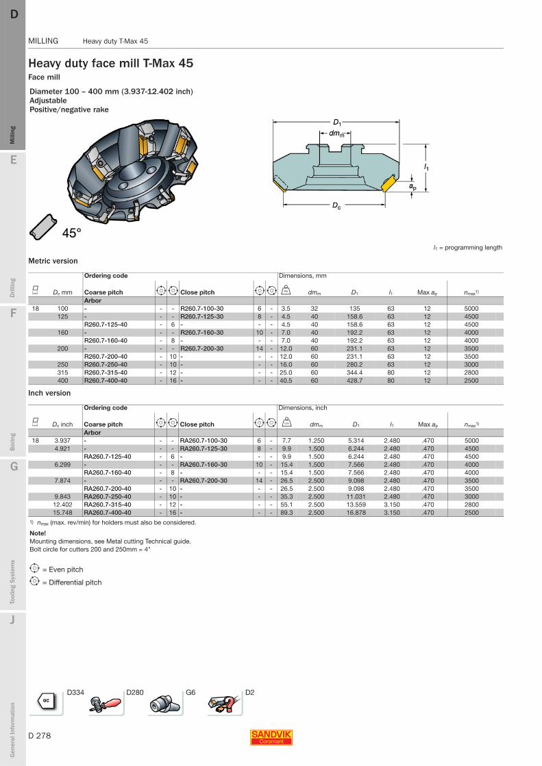
D 278
MILLING Heavy duty T-Max 45
E
Mill
ing
Drilli
ng
F
Bor
ing
G
Tool
ing
Syst
ems
J
Gen
eral
Info
rmat
ion
DDM
illin
g
MILLING Heavy duty T-Max 45
Heavy duty face mill T-Max 45Face mill
Metric version
Inch version
Diameter 100 – 400 mm (3.937-12.402 inch)AdjustablePositive/negative rake
l1 = programming length
Ordering code Dimensions, mm
K Dc mm Coarse pitch e i Close pitch e i U dmm D1 l1 Max ap nmax1)
Arbor18 100 - - - R260.7-100-30 6 - 3.5 32 135 63 12 5000
125 - - - R260.7-125-30 8 - 4.5 40 158.6 63 12 4500R260.7-125-40 - 6 - - - 4.5 40 158.6 63 12 4500
160 - - - R260.7-160-30 10 - 7.0 40 192.2 63 12 4000R260.7-160-40 - 8 - - - 7.0 40 192.2 63 12 4000
200 - - - R260.7-200-30 14 - 12.0 60 231.1 63 12 3500R260.7-200-40 - 10 - - - 12.0 60 231.1 63 12 3500
250 R260.7-250-40 - 10 - - - 16.0 60 280.2 63 12 3000315 R260.7-315-40 - 12 - - - 25.0 60 344.4 80 12 2800400 R260.7-400-40 - 16 - - - 40.5 60 428.7 80 12 2500
Ordering code Dimensions, inch
K Dc inch Coarse pitch e i Close pitch e i V dmm D1 l1 Max ap nmax1)
Arbor18 3.937 - - - RA260.7-100-30 6 - 7.7 1.250 5.314 2.480 .470 5000
4.921 - - - RA260.7-125-30 8 - 9.9 1.500 6.244 2.480 .470 4500RA260.7-125-40 - 6 - - - 9.9 1.500 6.244 2.480 .470 4500
6.299 - - - RA260.7-160-30 10 - 15.4 1.500 7.566 2.480 .470 4000RA260.7-160-40 - 8 - - - 15.4 1.500 7.566 2.480 .470 4000
7.874 - - - RA260.7-200-30 14 - 26.5 2.500 9.098 2.480 .470 3500RA260.7-200-40 - 10 - - - 26.5 2.500 9.098 2.480 .470 3500
9.843 RA260.7-250-40 - 10 - - - 35.3 2.500 11.031 2.480 .470 300012.402 RA260.7-315-40 - 12 - - - 55.1 2.500 13.559 3.150 .470 280015.748 RA260.7-400-40 - 16 - - - 89.3 2.500 16.878 3.150 .470 2500
1) nmax (max. rev/min) for holders must also be considered.
Note!Mounting dimensions, see Metal cutting Technical guide.Bolt circle for cutters 200 and 250mm = 4"
e = Even pitch
i = Differential pitch
D334 D280 G6 D2
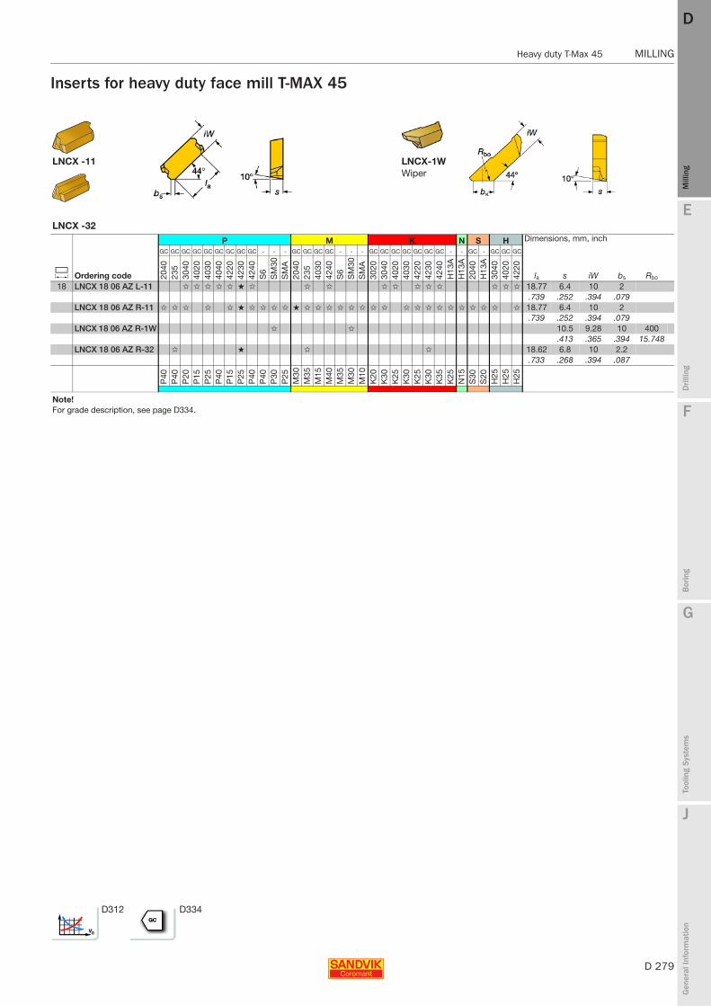
E
D 279
Mill
ing
Drilli
ng
F
Bor
ing
G
Tool
ing
Syst
ems
J
Gen
eral
Info
rmat
ion
DD
Mill
ing
Heavy duty T-Max 45 MILLING
MILLING Heavy duty T-Max 45
Inserts for heavy duty face mill T-MAX 45
LNCX -11 LNCX-1WWiper
LNCX -32
P M K N S H Dimensions, mm, inch
C Ordering code
GC GC GC GC GC GC GC GC GC - - - GC GC GC GC - - - GC GC GC GC GC GC GC - - GC - GC GC GC
la s iW bs Rbo2040
235
3040
4020
4030
4040
4220
4230
4240
S6
SM
30S
MA
2040
235
4030
4240
S6
SM
30S
MA
3020
3040
4020
4030
4220
4230
4240
H13
AH
13A
2040
H13
A30
4040
2042
20
18 LNCX 18 06 AZ L-11 ✩ ✩ ✩ ✩ ✩ ★ ✩ ✩ ✩ ✩ ✩ ✩ ✩ ✩ ✩ ✩ ✩ 18.77 6.4 10 2.739 .252 .394 .079
LNCX 18 06 AZ R-11 ✩ ✩ ✩ ✩ ✩ ★ ✩ ✩ ✩ ✩ ★ ✩ ✩ ✩ ✩ ✩ ✩ ✩ ✩ ✩ ✩ ✩ ✩ ✩ ✩ ✩ ✩ ✩ ✩ 18.77 6.4 10 2.739 .252 .394 .079
LNCX 18 06 AZ R-1W ✩ ✩ 10.5 9.28 10 400.413 .365 .394 15.748
LNCX 18 06 AZ R-32 ✩ ★ ✩ ✩ 18.62 6.8 10 2.2.733 .268 .394 .087
P40
P40
P20
P15
P25
P40
P15
P25
P40
P40
P30
P25
M30
M35
M15
M40
M35
M30
M10
K20
K30
K25
K30
K25
K30
K35
K25
N15
S30
S20
H25
H25
H25
Note!For grade description, see page D334.
D312 D334
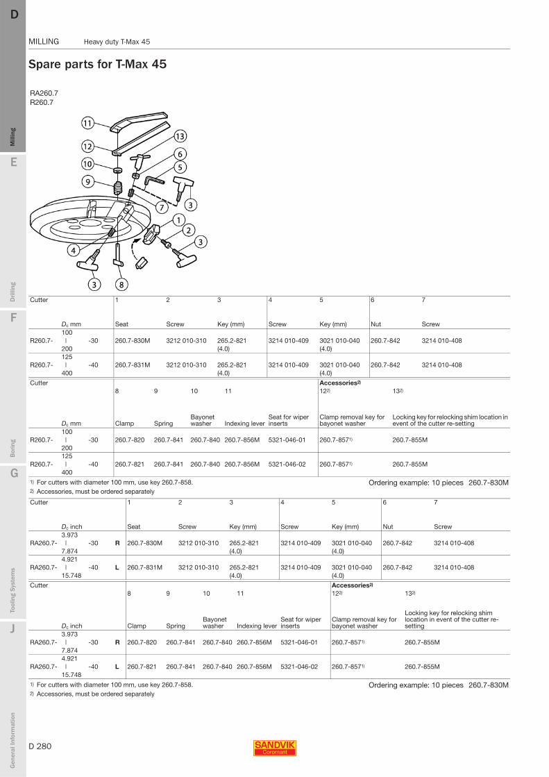
D 280
MILLING Heavy duty T-Max 45
E
Mill
ing
Drilli
ng
F
Bor
ing
G
Tool
ing
Syst
ems
J
Gen
eral
Info
rmat
ion
DDM
illin
g
MILLING Heavy duty T-Max 45
Spare parts for T-Max 45
RA260.7R260.7
Cutter 1 2 3 4 5 6 7
Dc mm Seat Screw Key (mm) Screw Key (mm) Nut Screw100
R260.7- | -30 260.7-830M 3212 010-310 265.2-821 3214 010-409 3021 010-040 260.7-842 3214 010-408200 (4.0) (4.0)125
R260.7- | -40 260.7-831M 3212 010-310 265.2-821 3214 010-409 3021 010-040 260.7-842 3214 010-408400 (4.0) (4.0)
Cutter Accessories2)
8 9 10 11 122) 132)
Dc mm Clamp SpringBayonet washer Indexing lever
Seat for wiper inserts
Clamp removal key for bayonet washer
Locking key for relocking shim location in event of the cutter re-setting
100R260.7- | -30 260.7-820 260.7-841 260.7-840 260.7-856M 5321-046-01 260.7-8571) 260.7-855M
200125
R260.7- | -40 260.7-821 260.7-841 260.7-840 260.7-856M 5321-046-02 260.7-8571) 260.7-855M400
1) For cutters with diameter 100 mm, use key 260.7-858. Ordering example: 10 pieces 260.7-830M2) Accessories, must be ordered separately
Cutter 1 2 3 4 5 6 7
Dc inch Seat Screw Key (mm) Screw Key (mm) Nut Screw3.973
RA260.7- | -30 R 260.7-830M 3212 010-310 265.2-821 3214 010-409 3021 010-040 260.7-842 3214 010-4087.874 (4.0) (4.0)4.921
RA260.7- | -40 L 260.7-831M 3212 010-310 265.2-821 3214 010-409 3021 010-040 260.7-842 3214 010-40815.748 (4.0) (4.0)
Cutter Accessories2)
8 9 10 11 122) 132)
Dc inch Clamp SpringBayonet washer Indexing lever
Seat for wiper inserts
Clamp removal key for bayonet washer
Locking key for relocking shim location in event of the cutter re-setting
3.973RA260.7- | -30 R 260.7-820 260.7-841 260.7-840 260.7-856M 5321-046-01 260.7-8571) 260.7-855M
7.8744.921
RA260.7- | -40 L 260.7-821 260.7-841 260.7-840 260.7-856M 5321-046-02 260.7-8571) 260.7-855M15.748
1) For cutters with diameter 100 mm, use key 260.7-858. Ordering example: 10 pieces 260.7-830M2) Accessories, must be ordered separately
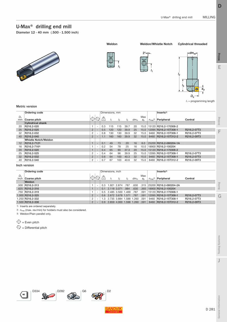
E
D 281
Mill
ing
Drilli
ng
F
Bor
ing
G
Tool
ing
Syst
ems
J
Gen
eral
Info
rmat
ion
DD
Mill
ing
U-Max® drilling end mill MILLING
MILLING U-Max® drilling end mill
U-Max® drilling end millDiameter 12 - 40 mm (.500 - 1.500 inch)
Metric version
Inch version
Weldon Weldon/Whistle Notch Cylindrical threaded
l1 = programming length
Ordering code Dimensions, mm Inserts1)
Dc mm Coarse pitch e i U l1 l2 l3 dmm
Max ap nmax2) Peripheral Central
Cylindrical shank20 R216.2-020 1 - 0.3 115 115 39.7 20 15.0 15120 R216.2-170308-225 R216.2-025 2 - 0.5 120 120 39.9 25 15.0 12095 R216.2-15T308-1 R216.2-07T332 R216.2-032 2 - 0.8 130 130 39.9 32 15.0 9460 R216.2-15T308-1 R216.2-07T340 R216.2-040 2 - 1.1 160 160 39.9 32 15.0 8460 R216.2-15T312-2 R216.2-09T3
Whistle Notch/Weldon12 R216.2-7123) 1 - 0.1 49 73 20 16 8.0 25200 R216.2-080204-1A16 R216.2-7163) 1 - 0.2 54 78 25 16 10.0 18900 R216.2-10020420 R216.2-520 1 - 0.4 65 90 37.3 20 15.0 15120 R216.2-170308-225 R216.2-525 2 - 0.4 64 96 39.9 25 15.0 12095 R216.2-15T308-1 R216.2-07T332 R216.2-532 2 - 0.6 64 100 40.3 32 15.0 9460 R216.2-15T308-1 R216.2-07T340 R216.2-540 2 - 0.7 67 103 40.6 32 15.0 8460 R216.2-15T312-2 R216.2-09T3
Ordering code Dimensions, inch Inserts1)
Dc inch Coarse pitch e i V l1 l2 l3 dmm
Max ap nmax2) Peripheral Central
Weldon.500 R216.2-313 1 - 0.3 1.921 2.874 .787 .630 .315 25200 R216.2-080204-2A.625 R216.2-316 1 - 0.1 2.118 3.071 .984 .630 .393 18900 R216.2-100204.750 R216.2-319 1 - 0.5 2.485 3.500 1.469 .787 .591 15120 R216.2-170308-1
1.000 R216.2-325 2 - 0.6 2.672 3.678 1.571 .787 .591 12095 R216.2-15T308-1 R216.2-07T31.250 R216.2-332 2 - 1.3 2.735 3.884 1.588 1.260 .591 9460 R216.2-15T308-1 R216.2-07T31.500 R216.2-338 2 - 0.9 2.859 4.000 1.598 1.260 .591 8460 R216.2-15T312-2 R216.2-09T31) Inserts are ordered separately.2) nmax (max. rev/min) for holders must also be considered.3) Weldon/Plain parallel only.
e = Even pitch
i = Differential pitch
D334 D282 G6 D2
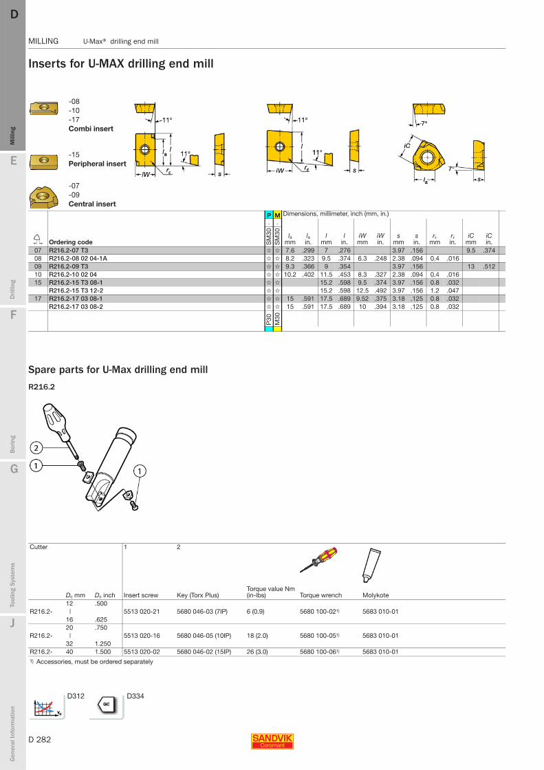
D 282
MILLING U-Max® drilling end mill
E
Mill
ing
Drilli
ng
F
Bor
ing
G
Tool
ing
Syst
ems
J
Gen
eral
Info
rmat
ion
DDM
illin
g
MILLING U-Max® drilling end mill
Inserts for U-MAX drilling end mill
Spare parts for U-Max drilling end mill
R216.2
-08-10-17Combi insert
-15Peripheral insert
-07-09Central insert
P M Dimensions, millimeter, inch (mm, in.)
E Ordering code
- -
lamm
lain.
lmm
lin.
iWmm
iWin.
smm
sin.
rεmm
rεin.
iCmm
iCin.S
M30
SM
30
07 R216.2-07 T3 ✩ ✩ 7.6 .299 7 .276 3.97 .156 9.5 .37408 R216.2-08 02 04-1A ✩ ✩ 8.2 .323 9.5 .374 6.3 .248 2.38 .094 0.4 .01609 R216.2-09 T3 ✩ ✩ 9.3 .366 9 .354 3.97 .156 13 .51210 R216.2-10 02 04 ✩ ✩ 10.2 .402 11.5 .453 8.3 .327 2.38 .094 0.4 .01615 R216.2-15 T3 08-1 ✩ ✩ 15.2 .598 9.5 .374 3.97 .156 0.8 .032
R216.2-15 T3 12-2 ✩ ✩ 15.2 .598 12.5 .492 3.97 .156 1.2 .04717 R216.2-17 03 08-1 ✩ ✩ 15 .591 17.5 .689 9.52 .375 3.18 .125 0.8 .032
R216.2-17 03 08-2 ✩ ✩ 15 .591 17.5 .689 10 .394 3.18 .125 0.8 .032
P30
M30
Cutter 1 2
Dc mm Dc inch Insert screw Key (Torx Plus)Torque value Nm (in-lbs) Torque wrench Molykote
12 .500R216.2- | 5513 020-21 5680 046-03 (7IP) 6 (0.9) 5680 100-021) 5683 010-01
16 .62520 .750
R216.2- | 5513 020-16 5680 046-05 (10IP) 18 (2.0) 5680 100-051) 5683 010-0132 1.250
R216.2- 40 1.500 5513 020-02 5680 046-02 (15IP) 26 (3.0) 5680 100-061) 5683 010-011) Accessories, must be ordered separately
D312 D334

E
D 283
Mill
ing
Drilli
ng
F
Bor
ing
G
Tool
ing
Syst
ems
J
Gen
eral
Info
rmat
ion
DD
Mill
ing
U-Max® chamfering end mill MILLING
MILLING U-Max® chamfering end mill
U-Max® chamfering end millDiameter 11.7-36.5 mm (.470-1.440 inch)Negative rake
Metric version
Inch version
Inserts for U-Max® chamfering end mill
Weldon Cylindrical
l1 = programming length
Ordering code Dimensions, mm
KDc
mm Coarse pitch e i D1 Dc2 Dc3 Dc4 l1 l2 l3 dmm
Max ap
Max ap nmax1)
Cylindrical shank12 11.7 R215.64-12A20-4512 1 - 19.4 27.1 3.29 26.4 175 175 37.8 20 7.9 8.1 25200
11.7 R215.64-12A20-6012 1 - 19.4 22.9 3.29 22.2 175 175 37.8 20 9.6 10.0 2520032.5 R215.64-32A32-4512 3 - 31.4 48.6 23.61 48.2 175 175 36 32 7.9 8.1 938536.5 R215.64-36A32-6012 3 - 27.2 47.8 27.79 47.6 175 175 36 32 9.6 10.0 8855
Ordering code Dimensions, inch
K Dc Coarse pitch e i D1 Dc2 Dc3 Dc4 l1 l2 l3 dmm
Max ap
Max ap nmax1)
Weldon12 .470 RA215.64-12M19-6012 1 - .724 .877 .122 .874 3.504 4.528 1.083 .750 .380 .394 25200
.500 RA215.64-12M19-4512 1 - .724 1.050 .150 1.091 3.504 4.528 1.083 .750 .310 .319 208451.280 RA215.64-32M32-4512 3 - 1.200 1.900 .930 1.898 4.140 5.276 1.083 1.250 .310 .319 93851.440 RA215.64-36M32-6012 3 - 1.070 1.870 1.090 1.880 4.140 5.276 1.083 1.250 .380 .394 8855
1) nmax (max. rev/min) for holders must also be considered.
e = Even pitch
i = Differential pitch
Maximum chamfer sizeU-MAX 45°
SPMT -WL SPMT -WH U-MAX 60°
P M K N S Dimensions, millimeter, inch (mm, in.)
J Ordering code
GC GC - GC - GC - - -
lmm
lin.
d1mm
d1in.
smm
sin.
rεmm
rεin.
iCmm
iCin.40
3040
40S
M30
4040
SM
3040
30H
13A
H13
AH
13A
12 SPMT 12 04 08-WH ✩ ✩ ✩ ✩ ✩ ✩ ✩ ✩ ✩ 12.7 .500 4.4 .173 4.76 .188 0.8 .032 12.7 .500SPMT 12 04 08-WL ✩ ✩ ✩ ✩ ✩ ✩ ✩ 12.7 .500 4.4 .173 4.76 .188 0.8 .032 12.7 .500
P25
P40
P30
M40
M30
K30
K25
N15
S20
D312 D334 D284 G6 D2

D 284
MILLING U-Max® chamfering end mill
E
Mill
ing
Drilli
ng
F
Bor
ing
G
Tool
ing
Syst
ems
J
Gen
eral
Info
rmat
ion
DDM
illin
g
MILLING U-Max® chamfering end mill
Spare parts for U-Max® chamfering end millRA215.64R215.64
Cutter 1 2Dc mm Dc inch
Insert screw Key (Torx Plus)Torque value Nm (in-lbs) Torque wrench Molykote
RA215.64 12 .460R215.64- | | 5513 020-29 5680 046-02 (15IP) 3.0 (26) 5680 100-061) 5683 010-01
36.5 1.440
1) Accessories, must be ordered separately
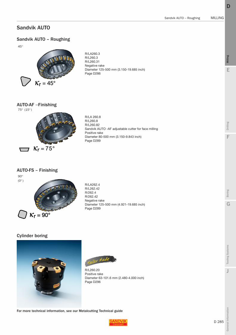
E
D 285
Mill
ing
Drilli
ng
F
Bor
ing
G
Tool
ing
Syst
ems
J
Gen
eral
Info
rmat
ion
DD
Mill
ing
Sandvik AUTO – Roughing MILLING
MILLING Sandvik AUTO – Roughing
Sandvik AUTO
Sandvik AUTO – Roughing
R/LA260.3R/L260.3R/L260.31Negative rakeDiameter 125-500 mm (3.150-19.685 inch)Page D286
Cylinder boring
R/L260.20Positive rakeDiameter 63-101.6 mm (2.480-4.000 inch)Page D296
AUTO-AF − Finishing
R/LA 260.8R/L260.8R/L260.82Sandvik AUTO -AF adjustable cutter for face millingPositive rakeDiameter 80-500 mm (3.150-9.843 inch)Page D289
AUTO-FS – Finishing
R/LA262.4R/L262.42R/262.4R/262.42Negative rakeDiameter 125-500 mm (4.921-19.685 inch)Page D289
For more technical information, see our Metalcutting Technical guide
45°
75° (15° )
90° (0° )

D 286
MILLING Sandvik AUTO – Roughing
E
Mill
ing
Drilli
ng
F
Bor
ing
G
Tool
ing
Syst
ems
J
Gen
eral
Info
rmat
ion
DDM
illin
g
MILLING Sandvik AUTO – Roughing
Sandvik AUTO – RoughingFace mill
Metric version
Inch version
Diameter 125-500 mm (3.150-19.685 inch)
Arbor Arbor
R/L260.3 R/L260.31 (Cap design)
Note!
Support body for Cap design must be ordered separately, see page D298.
l1 = programming length
Ordering code Dimensions, mm
D Dc mm Close pitch e i U dmm D1 l11)Max ap nmax2) Support body
Arbor12 125 R/L260.3-125M-10 20 - 5.7 40 145.2 63 6.0 1400
160 R/L260.3-160M-10 26 - 8.9 40 180.2 63 6.0 1250200 R/L260.3-200M-10 32 - 17.5 60 220.2 63 6.0 1100
Cap mounting12 250 R/L260.31-250-10 40 - 19.0 270.2 63 6.0 1000 260-425M-1
315 R/L260.31-315-10 50 - 25.0 335.2 63 6.0 900 260-431M-1355 R/L260.31-355-10 56 - 30.0 375.2 63 6.0 800 260-435M-1400 R/L260.31-400-10 64 - 35.0 420.2 63 6.0 800 260-440M-1500 R/L260.31-500-10 80 - 51.0 520.2 63 6.0 700 260-450M-1
Ordering code Dimensions, inch
D Dc inch Close pitch e i V dmm D1 l11)Max ap nmax2)
Arbor12 3.150 R/LA260.3-080M-10 10 - 5.5 1.000 3.945 2.375 .236 1700
3.937 R/LA260.3-100M-10 14 - 7.9 1.250 4.732 2.375 .236 15504.921 R/LA260.3-125M-10 20 - 11.9 1.500 5.716 2.375 .236 14006.299 R/LA260.3-160M-10 26 - 26.9 1.500 7.094 2.375 .236 12507.874 R/LA260.3-200M-10 32 - 38.6 2.500 8.669 2.375 .236 11009.843 R/LA260.3-250M-10 40 - 55.1 2.500 10.638 2.375 .236 1000
12.402 R/LA260.3-315M-10 50 - 88.2 2.500 13.197 2.375 .236 90013.976 R/LA260.3-355M-10 56 - 105.8 2.500 14.772 2.375 .236 80015.748 R/LA260.3-400M-10 64 - 121.3 2.500 16.543 2.375 .236 80019.685 R/LA260.3-500M-10 80 - 198.4 2.500 20.480 2.375 .236 700
1) With precision inserts.2) nmax (max. rev/min) for holders must also be considered.
Note!Support body dimensions, see page D298.Mounting dimensions, see Metal cutting Technical guide.
Bolt circle for cutters 200 and 250mm = 4"
e = Even pitch
i = Differential pitch
D287 D288 G6 D2

E
D 287
Mill
ing
Drilli
ng
F
Bor
ing
G
Tool
ing
Syst
ems
J
Gen
eral
Info
rmat
ion
DD
Mill
ing
Sandvik AUTO – Roughing MILLING
MILLING Sandvik AUTO – Roughing
Inserts for Sandvik AUTO cutters
Advanced cutting materials
WL CA ANKM ANEKX
P M K H Dimensions, millimeter, inch (mm, in.)
D Ordering code
GC GC GC GC GC GC GC GC GC GC GC
Max ap
mm
Max apin.
iCmm
iCin.
smm
sin.
bsmm
bsin.
lamm
lain.
rεmm
rεin.30
4042
3042
4042
3042
4030
4042
3042
40K
20D
K20
W30
40
Lig
ht
12 TNEF 12 04 AN-WL ✩ ✩ ✩ ✩ 6 .236 12.7 .500 4.76 .188 1.75 .069 12 .472 2 .079
Med
ium
12 TNEF 12 04 AN-KM ✩ ✩ 6 .236 12.7 .500 4.76 .188 1.25 .049 12 .472 2 .079TNEF 12 04 AN-KX ✩ 6 .236 12.7 .500 4.76 .188 1.25 .049 12 .472TNEF 12 04 AN-CA ✩ ✩ ✩ ✩ 6 .236 12.7 .500 4.76 .188 1.5 .059 12 .472 3 .118TNHF 12 04 AN-CA ✩ ✩ ✩ ✩ ✩ ✩ 6 .236 12.7 .500 4.76 .188 1.5 .059 12 .472 3 .118TNEN 12 04 AN ✩ ✩ ✩ ✩ 6 .236 12.7 .500 4.76 .188 2.5 .098 12 .472
P20
P25
P40
M15
M40
K30
K30
K35
K20
K25
H25
TNCNANEAN
K H Dimensions, millimeter, inch (mm, in.)
D Ordering code
CC CCMax ap
mm
Max apin.
iCmm
iCin.
smm
sin.
bsmm
bsin.
lamm
lain.61
9061
90
Lig
ht
12 TNCN 12 04 ANE ✩ ✩ 6 .236 12.7 .500 4.76 .188 2.5 .098 12 .472
Med
ium
12 TNCN 12 04 AN ✩ ✩ 6 .236 12.7 .500 4.76 .188 2.5 .098 12 .472
K10
H10
D312 D305 D334 D2
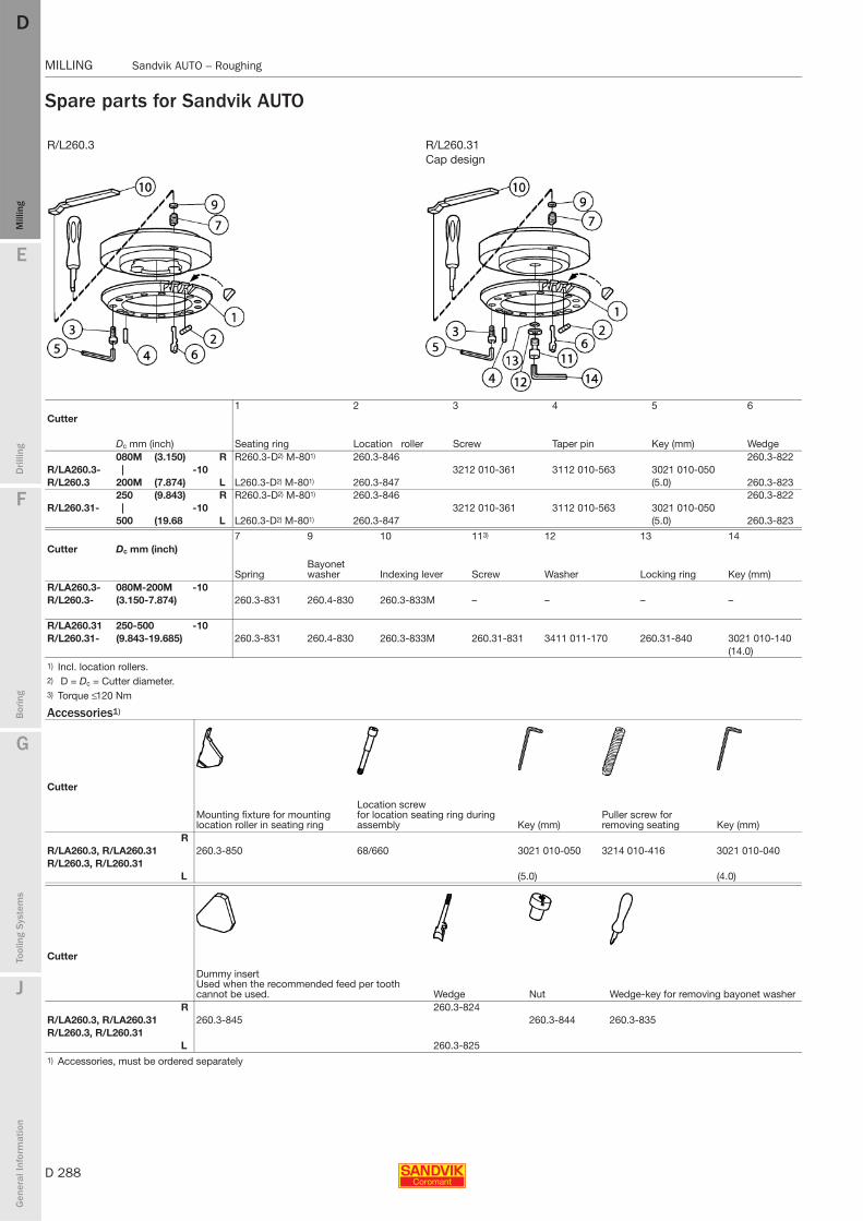
D 288
MILLING Sandvik AUTO – Roughing
E
Mill
ing
Drilli
ng
F
Bor
ing
G
Tool
ing
Syst
ems
J
Gen
eral
Info
rmat
ion
DDM
illin
g
MILLING Sandvik AUTO – Roughing
Spare parts for Sandvik AUTO
R/L260.3 R/L260.31 Cap design
1 2 3 4 5 6Cutter
Dc mm (inch) Seating ring Location roller Screw Taper pin Key (mm) Wedge080M (3.150) R R260.3-D2) M-801) 260.3-846 260.3-822
R/LA260.3- | -10 3212 010-361 3112 010-563 3021 010-050R/L260.3 200M (7.874) L L260.3-D2) M-801) 260.3-847 (5.0) 260.3-823
250 (9.843) R R260.3-D2) M-801) 260.3-846 260.3-822R/L260.31- | -10 3212 010-361 3112 010-563 3021 010-050
500 (19.68 L L260.3-D2) M-801) 260.3-847 (5.0) 260.3-823
7 9 10 113) 12 13 14Cutter Dc mm (inch)
SpringBayonet washer Indexing lever Screw Washer Locking ring Key (mm)
R/LA260.3- 080M-200M -10R/L260.3- (3.150-7.874) 260.3-831 260.4-830 260.3-833M – – – –
R/LA260.31 250-500 -10R/L260.31- (9.843-19.685) 260.3-831 260.4-830 260.3-833M 260.31-831 3411 011-170 260.31-840 3021 010-140
(14.0)1) Incl. location rollers.2) D = Dc = Cutter diameter.3) Torque ≤ 120 Nm
Accessories1)
Cutter
Mounting fixture for mounting location roller in seating ring
Location screw for location seating ring during assembly Key (mm)
Puller screw for removing seating Key (mm)
RR/LA260.3, R/LA260.31 260.3-850 68/660 3021 010-050 3214 010-416 3021 010-040R/L260.3, R/L260.31
L (5.0) (4.0)
Cutter
Dummy insert Used when the recommended feed per tooth cannot be used. Wedge Nut Wedge-key for removing bayonet washer
R 260.3-824R/LA260.3, R/LA260.31 260.3-845 260.3-844 260.3-835R/L260.3, R/L260.31
L 260.3-8251) Accessories, must be ordered separately

E
D 289
Mill
ing
Drilli
ng
F
Bor
ing
G
Tool
ing
Syst
ems
J
Gen
eral
Info
rmat
ion
DD
Mill
ing
AUTO-AF − Finishing MILLING
MILLING AUTO-AF − Finishing
AUTO-AF − FinishingFace mill
Metric version
Diameter 80 - 500 mmAdjustablePositive Arbor Arbor
R/L260.8 R/L260.82 (Cap design)Note! Support body for Cap design must be ordered separately, see page D298.
l1 = programming length
Ordering code Insert type Dimensions, mm
KDc
mm Extra close pitch F L U dmm D1 Dc2 l1Max ap nmax1) Support body
Arbor12 80 R/L260.8-080Q22-12H-F 8 1.5 22 84.9 84 63 1.0 5985
R/L260.8-080Q22-12H-FL 7 1 1.5 22 84.9 84 63 1.0 5985100 R/L260.8-100Q32-12H-F 10 2.0 32 103.6 104 63 1.0 5350
R/L260.8-100Q32-12H-FL 9 1 2.0 32 103.6 104 63 1.0 5350125 R/L260.8-125Q40-12H-F 14 3.0 40 127.6 129 63 1.0 4785
R/L260.8-125Q40-12H-FL 12 2 3.0 40 127.6 129 63 1.0 4785160 R/L260.8-160Q40-12H-F 18 5.0 40 161.8 164 63 1.0 4230
R/L260.8-160Q40-12H-FL 15 3 5.0 40 161.8 164 63 1.0 4230200 R/L260.8-200Q60-12H-F 24 8.0 60 201.1 204 63 1.0 3785
R/L260.8-200Q60-12H-FL 20 4 8.0 60 201.1 204 63 1.0 3785250 R/L260.8-250Q60-12H-F 30 13.0 60 250.6 254 63 1.0 3385
R/L260.8-250Q60-12H-FL 25 5 13.0 60 250.6 254 63 1.0 3385Cap mounting
12 250 R/L260.82-250-12H-F 30 8.0 250.6 254 63 1.0 3385 260-425M-1R/L260.82-250-12H-FL 25 5 8.0 250.6 254 63 1.0 3385 260-425M-1
315 R/L260.82-315-12H-F 32 13.0 315.2 319 63 1.0 3015 260-431M-1R/L260.82-315-12H-FL 28 4 13.0 315.2 319 63 1.0 3015 260-431M-1
355 R/L260.82-355-12H-F 40 15.0 355 359 63 1.0 2840 260-435M-1R/L260.82-355-12H-FL 36 4 15.0 355 359 63 1.0 2840 260-435M-1
400 R/L260.82-400-12H-F 40 18.0 399.8 404.0 63 1.0 2675 260-440M-1R/L260.82-400-12H-FL 36 4 18.0 399.8 404.0 63 1.0 2675 260-440M-1
500 R/L260.82-500-12H-F 48 44.0 499.8 504.0 63 1.0 2395 260-450M-1R/L260.82-500-12H-FL 42 6 44.0 499.8 504.0 63 1.0 2395 260-450M-1
1) nmax (max. rev/min) for holders must also be considered.
Note!Support body dimensions, see page D298.Mounting dimensions, see Metal cutting Technical guide.
Bolt circle for cutters 200 and 250mm = 4"
e = Even pitch
i = Differential pitch
When -F and -L inserts are combined in the same cutter (FL), the -F insert should be adjusted 0.01 mm below the -L insert.
D291 D292 G6 D2
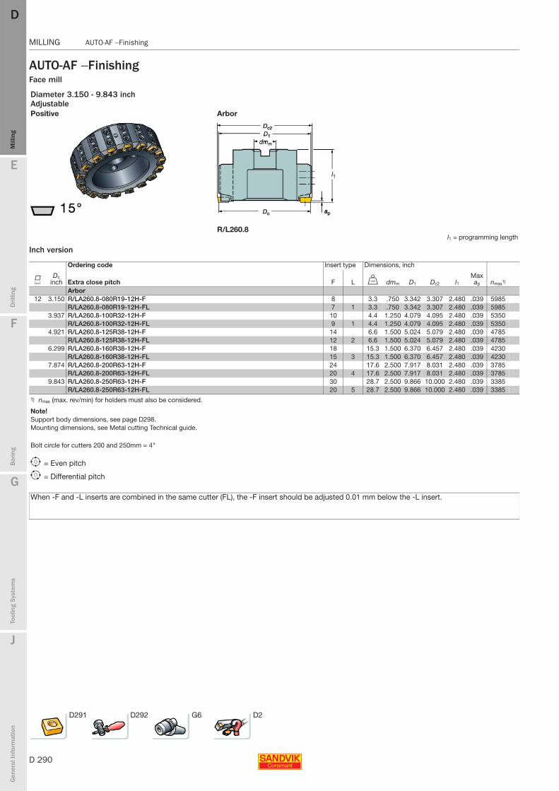
D 290
MILLING AUTO-AF − Finishing
E
Mill
ing
Drilli
ng
F
Bor
ing
G
Tool
ing
Syst
ems
J
Gen
eral
Info
rmat
ion
DDM
illin
g
MILLING AUTO-AF − Finishing
AUTO-AF − FinishingFace mill
Inch version
Diameter 3.150 - 9.843 inchAdjustablePositive Arbor
R/L260.8l1 = programming length
Ordering code Insert type Dimensions, inch
KDc
inch Extra close pitch F L V dmm D1 Dc2 l1Max ap nmax1)
Arbor12 3.150 R/LA260.8-080R19-12H-F 8 3.3 .750 3.342 3.307 2.480 .039 5985
R/LA260.8-080R19-12H-FL 7 1 3.3 .750 3.342 3.307 2.480 .039 59853.937 R/LA260.8-100R32-12H-F 10 4.4 1.250 4.079 4.095 2.480 .039 5350
R/LA260.8-100R32-12H-FL 9 1 4.4 1.250 4.079 4.095 2.480 .039 53504.921 R/LA260.8-125R38-12H-F 14 6.6 1.500 5.024 5.079 2.480 .039 4785
R/LA260.8-125R38-12H-FL 12 2 6.6 1.500 5.024 5.079 2.480 .039 47856.299 R/LA260.8-160R38-12H-F 18 15.3 1.500 6.370 6.457 2.480 .039 4230
R/LA260.8-160R38-12H-FL 15 3 15.3 1.500 6.370 6.457 2.480 .039 42307.874 R/LA260.8-200R63-12H-F 24 17.6 2.500 7.917 8.031 2.480 .039 3785
R/LA260.8-200R63-12H-FL 20 4 17.6 2.500 7.917 8.031 2.480 .039 37859.843 R/LA260.8-250R63-12H-F 30 28.7 2.500 9.866 10.000 2.480 .039 3385
R/LA260.8-250R63-12H-FL 20 5 28.7 2.500 9.866 10.000 2.480 .039 33851) nmax (max. rev/min) for holders must also be considered.
Note!Support body dimensions, see page D298.Mounting dimensions, see Metal cutting Technical guide.
Bolt circle for cutters 200 and 250mm = 4"
e = Even pitch
i = Differential pitch
When -F and -L inserts are combined in the same cutter (FL), the -F insert should be adjusted 0.01 mm below the -L insert.
D291 D292 G6 D2

E
D 291
Mill
ing
Drilli
ng
F
Bor
ing
G
Tool
ing
Syst
ems
J
Gen
eral
Info
rmat
ion
DD
Mill
ing
AUTO-AF − Finishing MILLING
MILLING AUTO-AF − Finishing
Inserts for AUTO AF Finishing
Insert design
CoroMill® 245 cassettes
N260.8 -F N260.8 -L
P K N S H Dimensions, millimeter, inch (mm, in.)
K Ordering code
GC GC CB - - - GC CB
smm
sin.
d1mm
d1in.
iWmm
iWin.
bsmm
bsin.
bomm
boin.
Rbomm
Rboin.30
4030
40C
B50
H13
AH
13A
H13
A30
40C
B50
12 N260.8-1204-F ✩ ✩ ✩ ✩ ✩ ✩ ✩ ✩ 12.7 .500 4.4 .173 4.76 .187 7.0 .276 7.0 .276 800 31.496N260.8-1204-L ✩ ✩ ✩ ✩ ✩ ✩ 12.7 .500 4.4 .173 4.76 .187 2.5 .098 2.5 .098 150 5.906
P20
K30
K05
K25
N15
S20
H25
H05
For grade description, see page D334.
Type F, wiper Type L- with long parallel lands and four cutting edges/
insert, right or left hand. To be used where high quality surface finish is required.
- with shorter parallel lands, have four right and four left hand cutting edges/insert.Low axial cutting forces facilitate milling of modern, thin walled components on weak machines, where L inserts should be used.L inserts can also be used in combination with F inserts.
Ordering codeR260.8-245 12 Right handL260.8-245 12 Left hand
D312 D305 D334 D2

D 292
MILLING AUTO-AF − Finishing
E
Mill
ing
Drilli
ng
F
Bor
ing
G
Tool
ing
Syst
ems
J
Gen
eral
Info
rmat
ion
DDM
illin
g
MILLING AUTO-AF − Finishing
Spare parts for AUTO-AF finishing
Cap designR/LA260.8-FR/L260.8-F R/L260.82-F R/L260.8-FL R/L260.82-FL R/LA260.8-FL
Cutter Insert type 1 2 3 4 5 6 7 8
Dc mm (inch) Cassette Eccentric pin Key (mm) Screw Washer Key (Torx Plus) Insert screw Key (Torx Plus)R/LA260.8 080 (3.150) R260.8-1-12FR/L260.8- | -F 265.2-874 265.2-821 3212 012-359 5541014-07 5680 048-07 416.1-834 5680 046-02
125 (4.921) L260.8-1-12F (4.0) (30IP) (15IP)R/LA260.8 160 (6.299) R260.8-2-12FR/L260.8- | -F 265.2-874 265.2-821 3212 012-359 5541014-07 5680 048-07 416.1-834 5680 046-02
250 (7.874) L260.8-2-12F (4.0) (30IP) (15IP)250 (9.843 ) R260.8-3-12F
R/L260.82- | -F 265.2-874 265.2-821 3212 012-359 5541014-07 5680 048-07 416.1-834 5680 046-02500 L260.8-3-12F (4.0) (30IP) (15IP)
R/LA260.8 080 (3.150) R260.8-1-12LR/L260.8- | -FL 265.2-874 265.2-821 3212 012-359 5541014-07 5680 048-07 416.1-834 5680 046-02
125 (4.921 ) L280.8-1-12L (4.0) (30IP) (15IP)R/LA260.8 160 (6.299) R260.8-2-12LR/L260.8- | -FL 265.2-874 265.2-821 3212 012-359 5541014-07 5680 048-07 416.1-834 5680 046-02
250 (7.874) L260.8-2-12L (4.0) (30IP) (15IP)250 (9.843) R260.8-3-12L
R/L260.82- | -FL 265.2-874 265.2-821 3212 012-359 5541014-07 5680 048-07 416.1-834 5680 046-02500 (19.685) L260.8-3-12L (4.0) (30IP) (15IP)80 (3.150) R260.8-245-12
R/L260.82- | -FL 265.2-874 265.2-821 3212 012-359 5541014-07 5680 048-07 5513 020-09 5680 046-02500 (19.685) L260.8-245-12 (4.0) (30IP) (15IP)
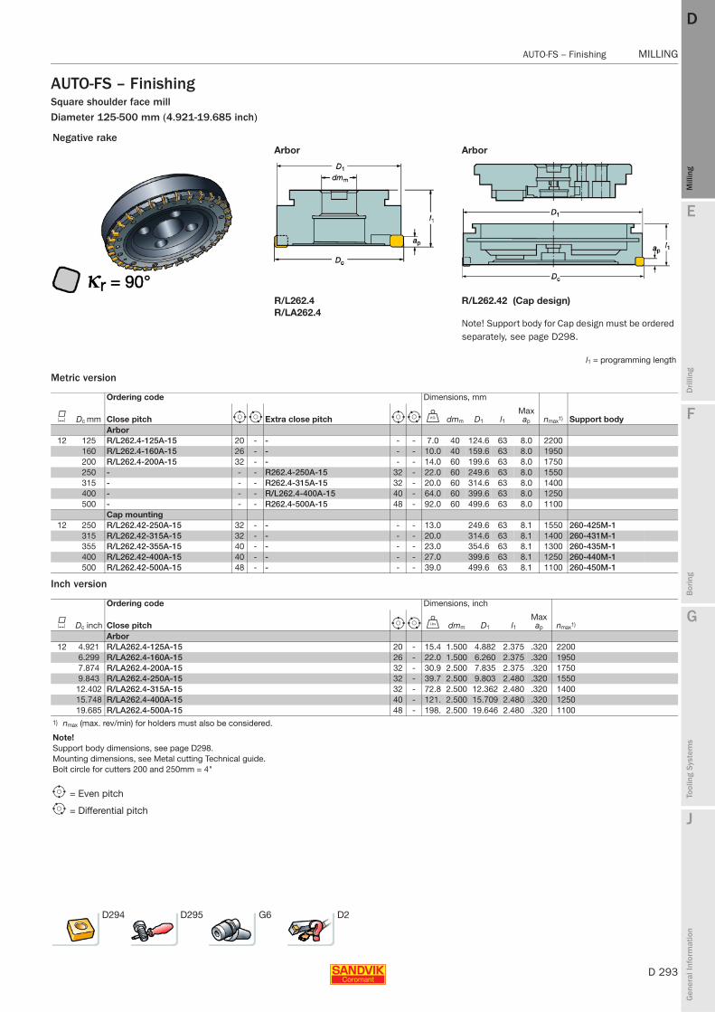
E
D 293
Mill
ing
Drilli
ng
F
Bor
ing
G
Tool
ing
Syst
ems
J
Gen
eral
Info
rmat
ion
DD
Mill
ing
AUTO-FS – Finishing MILLING
MILLING AUTO-FS – Finishing
AUTO-FS – FinishingSquare shoulder face millDiameter 125-500 mm (4.921-19.685 inch)
Metric version
Inch version
Negative rakeArbor Arbor
R/L262.4 R/L262.42 (Cap design)R/LA262.4
Note! Support body for Cap design must be ordered separately, see page D298.
l1 = programming length
Ordering code Dimensions, mm
K Dc mm Close pitch e i Extra close pitch e i U dmm D1 l1Max ap nmax1) Support body
Arbor12 125 R/L262.4-125A-15 20 - - - - 7.0 40 124.6 63 8.0 2200
160 R/L262.4-160A-15 26 - - - - 10.0 40 159.6 63 8.0 1950200 R/L262.4-200A-15 32 - - - - 14.0 60 199.6 63 8.0 1750250 - - - R262.4-250A-15 32 - 22.0 60 249.6 63 8.0 1550315 - - - R262.4-315A-15 32 - 20.0 60 314.6 63 8.0 1400400 - - - R/L262.4-400A-15 40 - 64.0 60 399.6 63 8.0 1250500 - - - R262.4-500A-15 48 - 92.0 60 499.6 63 8.0 1100
Cap mounting12 250 R/L262.42-250A-15 32 - - - - 13.0 249.6 63 8.1 1550 260-425M-1
315 R/L262.42-315A-15 32 - - - - 20.0 314.6 63 8.1 1400 260-431M-1355 R/L262.42-355A-15 40 - - - - 23.0 354.6 63 8.1 1300 260-435M-1400 R/L262.42-400A-15 40 - - - - 27.0 399.6 63 8.1 1250 260-440M-1500 R/L262.42-500A-15 48 - - - - 39.0 499.6 63 8.1 1100 260-450M-1
Ordering code Dimensions, inch
K Dc inch Close pitch e i V dmm D1 l1Max ap nmax1)
Arbor12 4.921 R/LA262.4-125A-15 20 - 15.4 1.500 4.882 2.375 .320 2200
6.299 R/LA262.4-160A-15 26 - 22.0 1.500 6.260 2.375 .320 19507.874 R/LA262.4-200A-15 32 - 30.9 2.500 7.835 2.375 .320 17509.843 R/LA262.4-250A-15 32 - 39.7 2.500 9.803 2.480 .320 1550
12.402 R/LA262.4-315A-15 32 - 72.8 2.500 12.362 2.480 .320 140015.748 R/LA262.4-400A-15 40 - 121. 2.500 15.709 2.480 .320 125019.685 R/LA262.4-500A-15 48 - 198. 2.500 19.646 2.480 .320 1100
1) nmax (max. rev/min) for holders must also be considered.
Note!Support body dimensions, see page D298.Mounting dimensions, see Metal cutting Technical guide.Bolt circle for cutters 200 and 250mm = 4"
e = Even pitch
i = Differential pitch
D294 D295 G6 D2
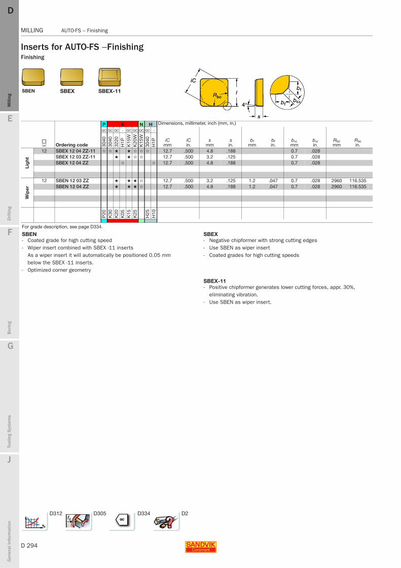
D 294
MILLING AUTO-FS – Finishing
E
Mill
ing
Drilli
ng
F
Bor
ing
G
Tool
ing
Syst
ems
J
Gen
eral
Info
rmat
ion
DDM
illin
g
MILLING AUTO-FS – Finishing
Inserts for AUTO-FS − FinishingFinishing
SBEN SBEX SBEX-11
P K N H Dimensions, millimeter, inch (mm, in.)
J Ordering code
GC GC GC - GC GC GC GC -
iCmm
iCin.
smm
sin.
bfmm
bfin.
bκεmm
bκεin.
Rbomm
Rboin.30
4030
4032
20H
1PK
15W
K20
WK
15W
3040
H1P
Lig
ht
12 SBEX 12 04 ZZ-11 ✩ ✩ ★ ★ ✩ ✩ ✩ 12.7 .500 4.8 .188 0.7 .028SBEX 12 03 ZZ-11 ★ ★ ✩ ✩ 12.7 .500 3.2 .125 0.7 .028SBEX 12 04 ZZ ✩ ✩ 12.7 .500 4.8 .188 0.7 .028
Wip
er
12 SBEN 12 03 ZZ ★ ★ ★ ✩ 12.7 .500 3.2 .125 1.2 .047 0.7 .028 2960 116.535SBEN 12 04 ZZ ★ ★ ★ ✩ 12.7 .500 4.8 .188 1.2 .047 0.7 .028 2960 116.535
P20
K30
K20
K05
K15
K25
H25
H10
For grade description, see page D334.
SBEN SBEX- Coated grade for high cutting speed- Wiper insert combined with SBEX -11 inserts
As a wiper insert it will automatically be positioned 0.05 mm below the SBEX -11 inserts.
- Optimized corner geometry
- Negative chipformer with strong cutting edges- Use SBEN as wiper insert- Coated grades for high cutting speeds
SBEX-11- Positive chipformer generates lower cutting forces, appr. 30%,
eliminating vibration. - Use SBEN as wiper insert.
D312 D305 D334 D2
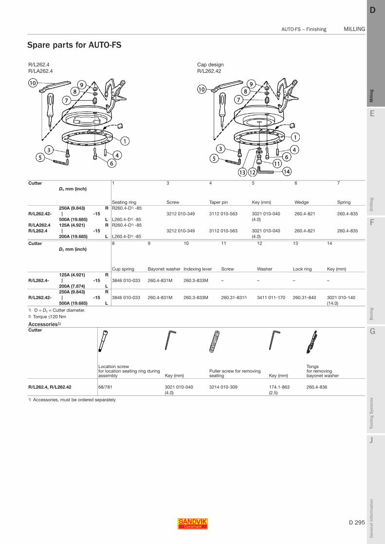
E
D 295
Mill
ing
Drilli
ng
F
Bor
ing
G
Tool
ing
Syst
ems
J
Gen
eral
Info
rmat
ion
DD
Mill
ing
AUTO-FS – Finishing MILLING
MILLING AUTO-FS – Finishing
Spare parts for AUTO-FS
R/L262.4 Cap designR/LA262.4 R/L262.42
Cutter 1 3 4 5 6 7Dc mm (inch)
Seating ring Screw Taper pin Key (mm) Wedge Spring250A (9.843) R R260.4-D1) -85
R/L262.42- | -15 3212 010-349 3112 010-563 3021 010-040 260.4-821 260.4-835500A (19.685) L L260.4-D1) -85 (4.0)
R/LA262.4 125A (4.921) R R260.4-D1) -85R/L262.4 | -15 3212 010-349 3112 010-563 3021 010-040 260.4-821 260.4-835
200A (19.685) L L260.4-D1) -85 (4.0)
Cutter 8 9 10 11 12 13 14Dc mm (inch)
Cup spring Bayonet washer Indexing lever Screw Washer Lock ring Key (mm)125A (4.921) R
R/L262.4- | -15 3846 010-033 260.4-831M 260.3-833M – – – –200A (7.874) L250A (9.843) R
R/L262.42- | -15 3846 010-033 260.4-831M 260.3-833M 260.31-8312) 3411 011-170 260.31-840 3021 010-140500A (19.685) L (14.0)
1) D = Dc = Cutter diameter.2) Torque ≤ 120 Nm
Accessories1)
Cutter
Location screw for location seating ring during assembly Key (mm)
Puller screw for removing seating Key (mm)
Tongs for removing bayonet washer
R/L262.4, R/L262.42 68/781 3021 010-040 3214 010-309 174.1-863 260.4-836(4.0) (2.5)
1) Accessories, must be ordered separately

D 296
MILLING Cylinder boring
E
Mill
ing
Drilli
ng
F
Bor
ing
G
Tool
ing
Syst
ems
J
Gen
eral
Info
rmat
ion
DDM
illin
g
MILLING Cylinder boring
Inserts for AUTO cylinder boring cutter R/L260.20
Spare parts
Inserts for AUTO cylinder boring cutter R/L260.20
SDKXSDMX
K N S Dimensions
J Ordering code
GC - - -
s la d1 iW3015
H13
AH
13A
H13
A
15 SDMX 15 06 08 ✩ .625 .433 .220 .250SDMX 15 06 ZN ✩ .625 .433 .220 .250SDKX 15 06 08 ✩ ✩ ✩ .625 .433 .220 .250SDKX 15 06 ZN ✩ ✩ ✩ .625 .433 .220 .250
R/L260.20
Cutter 1 2
Insert screw Key (Torx Plus) Torque value Nm (in-lbs) MolykoteR/L260.20 5513 016-01 5680 048-04 (20IP) 5.0 (44.3) 5683 010-011) Accessories, must be ordered separately
D312 D334 D2 D305
Sandvik Auto cylinder boring cutter
A positive cutter for roughing of cylinder bores.- A Tailor Made concept for most cylinder bores currently on the market.- Operates with low cutting forces.- Improved bore size control, better consistency.- Reduced tool and service costs.- Inserts with parallel land result in better surface, i.e. reduced withdrawal
marks.- The grade profile provides the right grade for any material and cutting data.- Recommended cutting depth .040-.240 inch.
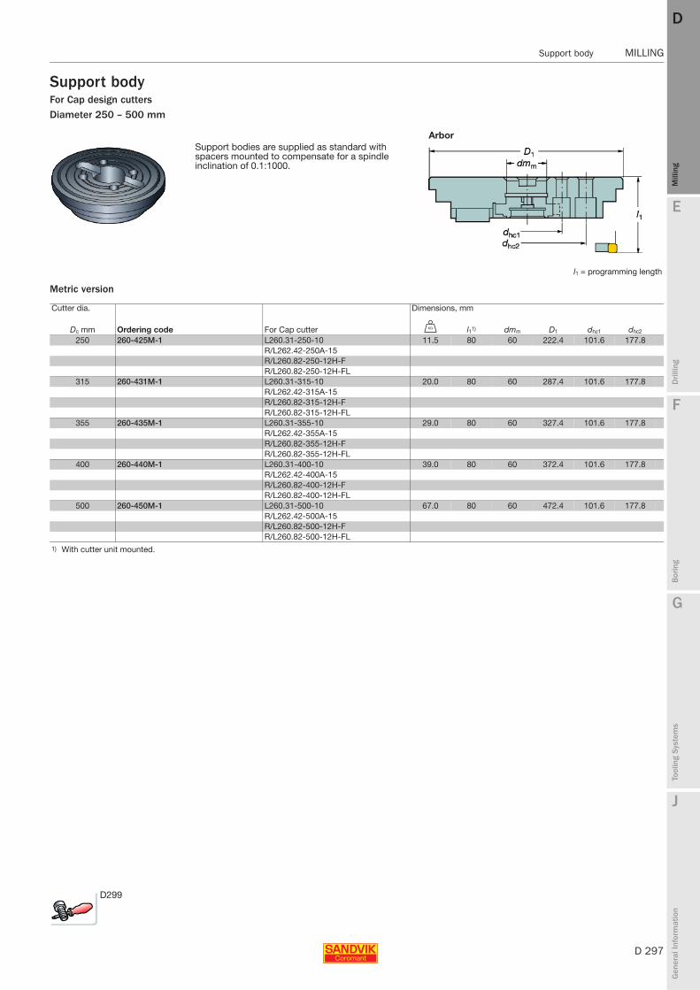
E
D 297
Mill
ing
Drilli
ng
F
Bor
ing
G
Tool
ing
Syst
ems
J
Gen
eral
Info
rmat
ion
DD
Mill
ing
Support body MILLING
MILLING Support body
Support bodyFor Cap design cuttersDiameter 250 – 500 mm
Metric version
ArborSupport bodies are supplied as standard with spacers mounted to compensate for a spindle inclination of 0.1:1000.
l1 = programming length
Cutter dia. Dimensions, mm
Dc mm Ordering code For Cap cutter U l11) dmm D1 dhc1 dhc2
250 260-425M-1 L260.31-250-10 11.5 80 60 222.4 101.6 177.8R/L262.42-250A-15R/L260.82-250-12H-FR/L260.82-250-12H-FL
315 260-431M-1 L260.31-315-10 20.0 80 60 287.4 101.6 177.8R/L262.42-315A-15R/L260.82-315-12H-FR/L260.82-315-12H-FL
355 260-435M-1 L260.31-355-10 29.0 80 60 327.4 101.6 177.8R/L262.42-355A-15R/L260.82-355-12H-FR/L260.82-355-12H-FL
400 260-440M-1 L260.31-400-10 39.0 80 60 372.4 101.6 177.8R/L262.42-400A-15R/L260.82-400-12H-FR/L260.82-400-12H-FL
500 260-450M-1 L260.31-500-10 67.0 80 60 472.4 101.6 177.8R/L262.42-500A-15R/L260.82-500-12H-FR/L260.82-500-12H-FL
1) With cutter unit mounted.
D299
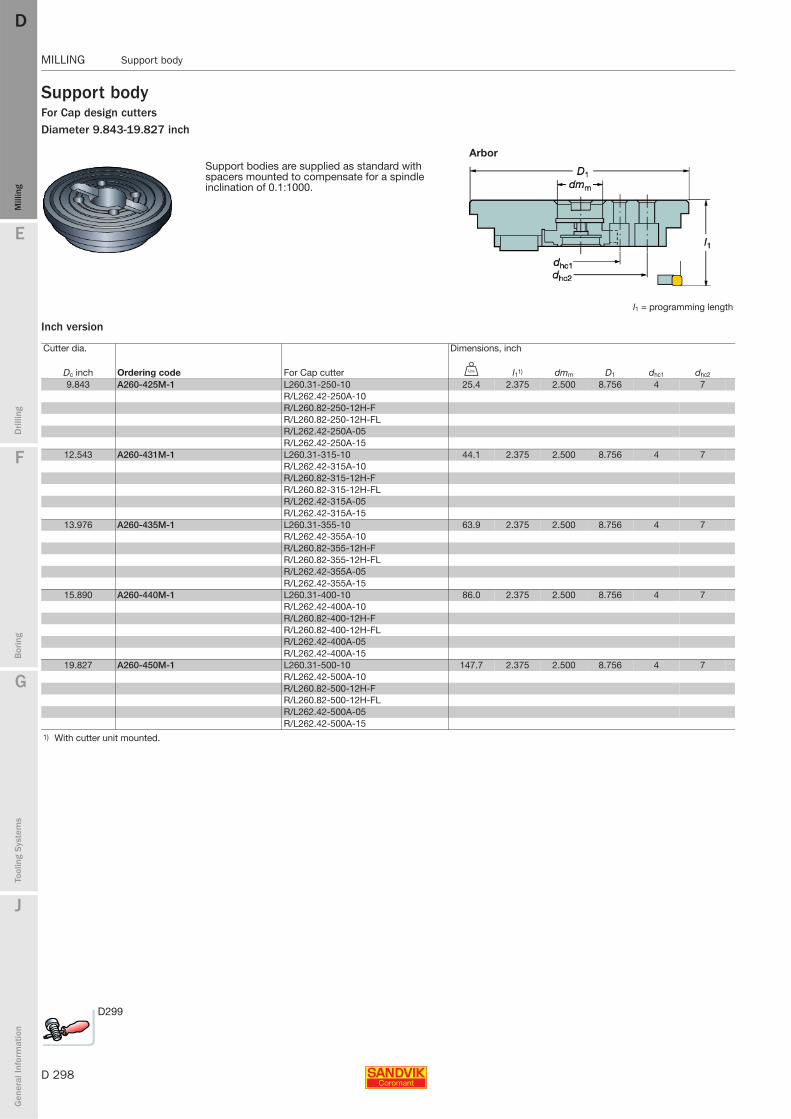
D 298
MILLING Support body
E
Mill
ing
Drilli
ng
F
Bor
ing
G
Tool
ing
Syst
ems
J
Gen
eral
Info
rmat
ion
DDM
illin
g
MILLING Support body
Support bodyFor Cap design cuttersDiameter 9.843-19.827 inch
Inch version
ArborSupport bodies are supplied as standard with spacers mounted to compensate for a spindle inclination of 0.1:1000.
l1 = programming length
Cutter dia. Dimensions, inch
Dc inch Ordering code For Cap cutter V l11) dmm D1 dhc1 dhc2
9.843 A260-425M-1 L260.31-250-10 25.4 2.375 2.500 8.756 4 7R/L262.42-250A-10R/L260.82-250-12H-FR/L260.82-250-12H-FLR/L262.42-250A-05R/L262.42-250A-15
12.543 A260-431M-1 L260.31-315-10 44.1 2.375 2.500 8.756 4 7R/L262.42-315A-10R/L260.82-315-12H-FR/L260.82-315-12H-FLR/L262.42-315A-05R/L262.42-315A-15
13.976 A260-435M-1 L260.31-355-10 63.9 2.375 2.500 8.756 4 7R/L262.42-355A-10R/L260.82-355-12H-FR/L260.82-355-12H-FLR/L262.42-355A-05R/L262.42-355A-15
15.890 A260-440M-1 L260.31-400-10 86.0 2.375 2.500 8.756 4 7R/L262.42-400A-10R/L260.82-400-12H-FR/L260.82-400-12H-FLR/L262.42-400A-05R/L262.42-400A-15
19.827 A260-450M-1 L260.31-500-10 147.7 2.375 2.500 8.756 4 7R/L262.42-500A-10R/L260.82-500-12H-FR/L260.82-500-12H-FLR/L262.42-500A-05R/L262.42-500A-15
1) With cutter unit mounted.
D299
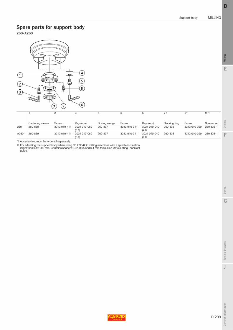
E
D 299
Mill
ing
Drilli
ng
F
Bor
ing
G
Tool
ing
Syst
ems
J
Gen
eral
Info
rmat
ion
DD
Mill
ing
Support body MILLING
MILLING Support body
Spare parts for support body260/A260
1 2 3 4 5 6 71) 81) 91)2)
Centering sleeve Screw Key (mm) Driving wedge Screw Key (mm) Backing ring Screw Spacer set260- 260-838 3212 010-411 3021 010-060 260-837 3212 010-311 3021 010-040 260-835 3213 010-399 260 836-1
(6.0) (4.0)A260- 260-839 3212 010-411 3021 010-060 260-837 3212 010-311 3021 010-040 260-835 3213 010-399 260 836-1
(6.0) (4.0)1) Accessories, must be ordered separately 2) For adjusting the support body when using R/L262.42 in milling machines with a spindle inclination
larger than 0.1:1000 mm. Contains spacers 0.02. 0.05 and 0.1 mm thick. See Metalcutting Technical guide.
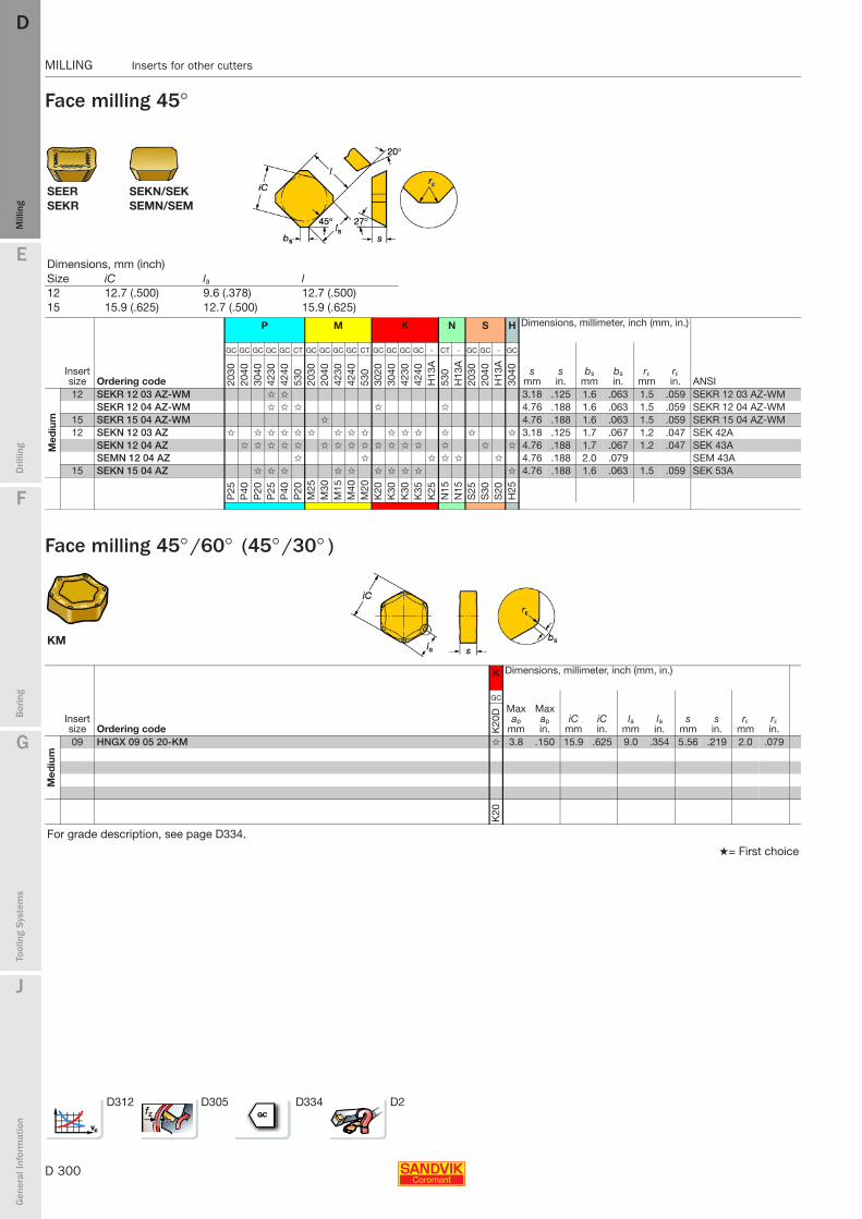
D 300
MILLING Inserts for other cutters
E
Mill
ing
Drilli
ng
F
Bor
ing
G
Tool
ing
Syst
ems
J
Gen
eral
Info
rmat
ion
DDM
illin
g
MILLING Inserts for other cutters
Face milling 45°
Face milling 45° /60° (45° /30° )
SEER SEKN/SEKSEKR SEMN/SEM
Dimensions, mm (inch)Size iC la l12 12.7 (.500) 9.6 (.378) 12.7 (.500)15 15.9 (.625) 12.7 (.500) 15.9 (.625)
P M K N S H Dimensions, millimeter, inch (mm, in.)
Insert size Ordering code
GC GC GC GC GC CT GC GC GC GC CT GC GC GC GC - CT - GC GC - GC
smm
sin.
bsmm
bsin.
rεmm
rεin. ANSI 20
3020
4030
4042
3042
4053
020
3020
4042
3042
4053
030
2030
4042
3042
40H
13A
530
H13
A20
3020
40H
13A
3040
Med
ium
12 SEKR 12 03 AZ-WM ✩ ✩ 3.18 .125 1.6 .063 1.5 .059 SEKR 12 03 AZ-WMSEKR 12 04 AZ-WM ✩ ✩ ✩ ✩ ✩ 4.76 .188 1.6 .063 1.5 .059 SEKR 12 04 AZ-WM
15 SEKR 15 04 AZ-WM ✩ 4.76 .188 1.6 .063 1.5 .059 SEKR 15 04 AZ-WM12 SEKN 12 03 AZ ✩ ✩ ✩ ✩ ✩ ✩ ✩ ✩ ✩ ✩ ✩ ✩ ✩ ✩ ✩ 3.18 .125 1.7 .067 1.2 .047 SEK 42A
SEKN 12 04 AZ ✩ ✩ ✩ ✩ ✩ ✩ ✩ ✩ ✩ ✩ ✩ ✩ ✩ ✩ ✩ ✩ 4.76 .188 1.7 .067 1.2 .047 SEK 43ASEMN 12 04 AZ ✩ ✩ ✩ ✩ ✩ ✩ 4.76 .188 2.0 .079 SEM 43A
15 SEKN 15 04 AZ ✩ ✩ ✩ ✩ ✩ ✩ ✩ ✩ ✩ ✩ 4.76 .188 1.6 .063 1.5 .059 SEK 53A
P25
P40
P20
P25
P40
P20
M25
M30
M15
M40
M20
K20
K30
K30
K35
K25
N15
N15
S25
S30
S20
H25
KM
K Dimensions, millimeter, inch (mm, in.)
Insert size Ordering code
GC
Max ap
mm
Max apin.
iCmm
iCin.
lamm
lain.
smm
sin.
rεmm
rεin.K
20D
Med
ium
09 HNGX 09 05 20-KM ✩ 3.8 .150 15.9 .625 9.0 .354 5.56 .219 2.0 .079
K20
For grade description, see page D334.
★= First choice
D312 D305 D334 D2

E
D 301
Mill
ing
Drilli
ng
F
Bor
ing
G
Tool
ing
Syst
ems
J
Gen
eral
Info
rmat
ion
DD
Mill
ing
Inserts for other cutters MILLING
MILLING Inserts for other cutters
Face milling 75° (15° )
SMKR -WH SPKN/SMK SPEX/SME
SNKN/SNK
SNKN SPKN SPEXSMKR-WH
Dimensions, mm (inch)Size iC l iW Rbo
12 12.7 (.500) 12.7 (.500) 12.7 (.500) 50015 15.9 (.625) 15.9 (.625) 15.9 (.625) 50019 19.0 (.750) 19.0 (.750) - -
P M K N H Dimensions, millimeter, inch (mm, in.)
Insert size Ordering code
GC GC GC GC CT - GC GC GC CT - GC GC GC - - - CT GC -
smm
sin.
bsmm
bsin.
bκεmm
bκεin. ANSI 20
4030
4042
3042
4053
0S
M30
2030
2040
4230
530
SM
3030
2030
4042
30H
13A
H1P
HM
530
3040
H1P
Med
ium
12 SPKN 12 03 ED R ✩ ✩ ✩ ✩ ✩ ✩ ✩ ✩ ✩ ✩ ✩ ✩ 3.18 .125 1.4 .055 1 .039 SMK 42E2 RSNKN 12 04 EN N ✩ ✩ ✩ 4.76 .188 1.5 .059 0.9 .035 SNK 43E2SPKN 12 03 ED L ✩ ✩ ✩ 3.18 .125 1.4 .055 1 .039 SMK 42E2 LSPKN 12 04 ED R ✩ 4.76 .188 1.4 .055 1 .039 SMK 43E2 R
15 SPKN 15 04 ED R ✩ ✩ ✩ ✩ ✩ ✩ ✩ 4.76 .188 1.4 .055 1 .039 SMK 53E2 RSPKN 15 04 ED L ✩ ✩ 4.76 .188 1.4 .055 1 .039 SMK 53E2 L
19 SPKN 19 04 ED R ✩ ✩ 4.76 .188 2.7 .106 1 .039 SMK 63E3 R
Hea
vy
12 SPKR 12 03 ED R-WH ✩ ✩ ✩ ✩ 3.18 .125 1.4 .055 SMKR 42E2 R-WHSPKR 12 04 ED R-WH ✩ ✩ ✩ 4.76 .188 1.4 .055 SMKR 43E2 R-WH
15 SPKR 15 04 ED R-WH ✩ ✩ ✩ ✩ 4.76 .188 1.4 .055 SMKR 53E2 R-WH19 SPKR 19 04 ED R-WH ✩ ✩ ✩ 4.76 .188 2.7 .106 SMKR 63E3 R-WH
Wip
er
12 SPEX 12 03 ED R-1 ✩ ✩ 3.18 .125 10.0 .394 SME 42E12 RSPEX 12 04 ED R-1 ✩ ✩ 4.76 .188 10.0 .394 SME 43E12 R
15 SPEX 15 04 ED R-1 ✩ ✩ ✩ 4.76 .188 10.0 .394 SME 53E12 R
P40
P20
P25
P40
P20
P30
M25
M30
M15
M20
M30
K20
K30
K30
K25
K05
K15
N15
H25
H10
For grade description, see page D334.
D312 D305 D334 D2

D 302
MILLING Inserts for other cutters
E
Mill
ing
Drilli
ng
F
Bor
ing
G
Tool
ing
Syst
ems
J
Gen
eral
Info
rmat
ion
DDM
illin
g
MILLING Inserts for other cutters
Shoulder milling 90° (0° )
Round inserts for other cutters
TPKR TPKN/TPK BPKX
P M K N S H Dimensions, mm, inch
J Ordering code
GC GC GC GC GC CT - - GC GC CT - GC GC GC GC - - CT - GC GC - GC
iC l s bs bκε αn° ANSI 2030
2040
3040
4230
4240
530
S6
SM
3020
3020
4053
0S
M30
3020
3040
4230
4240
H13
AH
M53
0H
13A
2030
2040
H13
A30
40
Med
ium
3/8 TPKN 16 03 PP R ✩ ✩ ✩ ✩ ✩ ✩ ✩ ✩ ✩ ✩ ✩ ✩ ✩ ✩ 9.5 16.5 3.2 1.2 1.0 11 TPK 32P2 R.375 .650 .125 .047 .039 11
3/4 BPKX 19 04 PD R ✩ ✩ 19.0 4.8 2.6 0.7 11 BPKX 19 04 PD R.750 .188 .102 .028 11
1/2 TPKN 22 04 PD R ✩ ✩ ✩ ✩ ✩ ✩ ✩ ✩ ✩ ✩ ✩ ✩ ✩ ✩ ✩ ✩ ✩ ✩ ✩ ✩ ✩ ✩ ✩ ✩ 12.7 22.0 4.8 1.4 0.7 11 TPK 43P2 R.500 .866 .188 .055 .028 11
BPKX 15 04 PD R 15.9 4.8 2.0 0.7 11 BPKX 15 04 PD R.625 .188 .079 .028 11
Hea
vy
3/8 TPKR 16 03 PP R-WH ✩ ✩ ✩ ✩ ✩ ✩ ✩ 9.5 16.5 3.2 1.2 11 TPKR 32P2 R-WH.375 .650 .125 .047 11
1/2 TPKR 22 04 PD R-WH ✩ ✩ ✩ ✩ ✩ ✩ ✩ 12.7 22.0 4.8 1.4 11 TPKR 43P2 R-WH.500 .866 .188 .055 11
P25
P40
P20
P25
P40
P20
P40
P30
M25
M30
M20
M30
K20
K30
K30
K35
K25
K15
N15
N15
S25
S30
S20
H25
For grade description, see page D334.
CeramicRPGN RNGN
RPGN RNGN
S
ISO L iC
CC
ANSI 6060
RNGN120700E 12 12.7 ✩ RNG45ARNGN 12 07 00T01020 12 12.7 ✩ RNG45T0320
RPGN060300E 06 1/4 ✩ RPG22ARPGN090300E 09 3/8 ✩ RPG32ARPGN120400E 12 1/2 ✩ RPG43A
S10
D312 D305 D334 D2
Rotating_Utfyllnadssidor.indd 4 2010-12-09 12:30:11
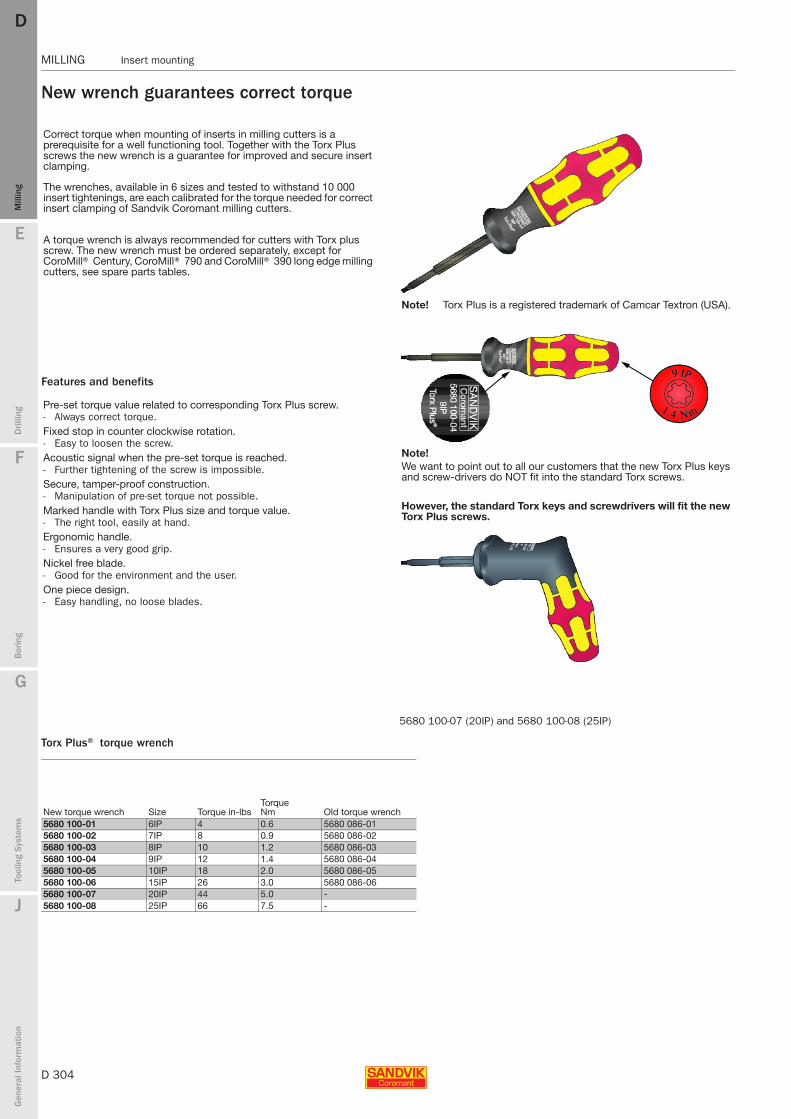
D 304
MILLING Insert mounting
E
Mill
ing
Drilli
ng
F
Bor
ing
G
Tool
ing
Syst
ems
J
Gen
eral
Info
rmat
ion
DDM
illin
g
MILLING Insert mounting
New wrench guarantees correct torque
Features and benefits
Torx Plus® torque wrench
Correct torque when mounting of inserts in milling cutters is a prerequisite for a well functioning tool. Together with the Torx Plus screws the new wrench is a guarantee for improved and secure insert clamping.
The wrenches, available in 6 sizes and tested to withstand 10 000 insert tightenings, are each calibrated for the torque needed for correct insert clamping of Sandvik Coromant milling cutters.
A torque wrench is always recommended for cutters with Torx plus screw. The new wrench must be ordered separately, except for CoroMill® Century, CoroMill® 790 and CoroMill® 390 long edge milling cutters, see spare parts tables.
Pre-set torque value related to corresponding Torx Plus screw.- Always correct torque.Fixed stop in counter clockwise rotation. - Easy to loosen the screw.Acoustic signal when the pre-set torque is reached.- Further tightening of the screw is impossible.Secure, tamper-proof construction.- Manipulation of pre-set torque not possible.Marked handle with Torx Plus size and torque value.- The right tool, easily at hand.Ergonomic handle.- Ensures a very good grip.Nickel free blade.- Good for the environment and the user.One piece design.- Easy handling, no loose blades.
New torque wrench Size Torque in-lbsTorque Nm Old torque wrench
5680 100-01 6IP 4 0.6 5680 086-015680 100-02 7IP 8 0.9 5680 086-025680 100-03 8IP 10 1.2 5680 086-035680 100-04 9IP 12 1.4 5680 086-045680 100-05 10IP 18 2.0 5680 086-055680 100-06 15IP 26 3.0 5680 086-065680 100-07 20IP 44 5.0 -5680 100-08 25IP 66 7.5 -
5680 100-07 (20IP) and 5680 100-08 (25IP)
Note! Torx Plus is a registered trademark of Camcar Textron (USA).
Note!We want to point out to all our customers that the new Torx Plus keys and screw-drivers do NOT fit into the standard Torx screws.
However, the standard Torx keys and screwdrivers will fit the new Torx Plus screws.
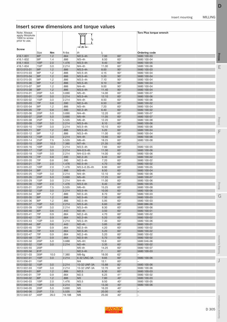
E
D 305
Mill
ing
Drilli
ng
F
Bor
ing
G
Tool
ing
Syst
ems
J
Gen
eral
Info
rmat
ion
DD
Mill
ing
Insert mounting MILLING
MILLING Insert mounting
Insert screw dimensions and torque valuesNote: Always apply Molykote 1000 to screw prior to use.
Torx Plus torque wrench
ScrewSize Nm ft-lbs th l2 Ordering code
416.1-831 8IP 1.2 .664 M2.5–4h 7.00 60° 5680 100-03416.1-832 9IP 1.4 .886 M3–4h 8.50 60° 5680 100-04416.1-833 10IP 2.0 1.476 M3.5–4h 9.40 60° 5680 100-05416.1-834 15IP 3.0 2.214 M4–4h 11.00 60° 5680 100-065513 015-01 9IP 1.2 .886 M3.5–4h 8.00 90° 5680 100-035513 015-03 9IP 1.2 .886 M3.5–4h 4.15 90° 5680 100-045513 015-04 9IP 1.2 .886 M3.5–4h 5.20 90° 5680 100-045513 015-05 9IP 1.2 .886 M3.5–4h 7.10 90° 5680 100-045513 015-06 9IP 1.2 .886 M3.5–4h 9.10 90° 5680 100-045513 015-07 9IP 1.2 .886 M4–4h 9.00 90° 5680 100-045513 015-08 9IP 1.2 .886 M3.5–4h 11.40 90° 5680 100-045513 016-01 20IP 5.0 3.690 M5–4h 14.00 60° 5680 100-075513 020-01 15IP 3.0 2.214 M3.5–4h 12.10 60° 5680 100-065513 020-02 15IP 3.0 2.214 M4–4h 8.50 60° 5680 100-065513 020-03 7IP 0.8 .590 M2.5–4h 6.50 60° 5680 100-025513 020-04 9IP 1.2 .886 M3–4h 7.20 60° 5680 100-045513 020-05 7IP 0.8 .590 M2.2–4h 6.40 60° 5680 100-025513 020-06 20IP 5.0 3.690 M4–4h 12.20 60° 5680 100-075513 020-07 20IP 5.0 3.690 M5–4h 11.05 60° 5680 100-075513 020-08 25IP 7.5 5.535 M6–4h 12.20 60° 5680 100-085513 020-09 15IP 3.0 2.214 M3.5–4h 8.10 60° 5680 100-065513 020-10 15IP 3.0 2.214 M3.5–4h 10.10 60° 5680 100-065513 020-11 9IP 1.2 .886 M3.5–4h 5.20 60° 5680 100-045513 020-12 9IP 1.2 .886 M3.5–4h 11.00 60° 5680 100-045513 020-13 15IP 3.0 2.214 M4–4h 13.60 60° 5680 100-065513 020-14 25IP 7.5 5.535 M6–4h 18.25 60° 5680 100-085513 020-15 30IP 10.0 7.380 M7–4h 21.35 60° –5513 020-16 10IP 3.0 2.214 M3.5–4h 7.60 60° 5680 100-055513 020-17 15IP 3.0 2.214 M4–0.5–4h 11.00 60° 5680 100-065513 020-18 15IP 3.0 2.214 M4–0.5–4h 14.00 60° 5680 100-065513 020-19 7IP 0.8 .590 M2.2–4h 6.40 60° 5680 100-025513 020-20 7IP 0.8 .590 M2.5–4h 7.20 60° 5680 100-025513 020-21 7IP 2.0 1.476 M2.5–4h 4.70 60° 5680 100-025513 020-22 10IP 2.0 1.476 M3.5–0.35–4h 8.90 60° 5680 100-055513 020-24 9IP 1.2 .886 M3–4h 8.50 60° 5680 100-045513 020-25 15IP 3.0 2.214 M4–4h 12.10 60° 5680 100-065513 020-26 20IP 5.0 3.690 M5–4h 17.25 60° 5680 100-075513 020-29 15IP 3.0 2.214 M4–4h 11.00 60° 5680 100-065513 020-30 10IP 2.0 1.476 M3.5-4h 9.40 60° 5680 100-055513 020-31 25IP 7.5 5.535 M6–4h 15.25 60° 5680 100-085513 020-32 15IP 3.0 2.214 M3.5–4h 10.00 60° 5680 100-065513 020-34 8IP 1.2 .886 M2.5–4h 8.70 60° 5680 100-035513 020-35 8IP 1.2 .886 M2.5–4h 7.30 60° 5680 100-035513 020-36 8IP 1.2 .886 M2.5–4h 5.95 60° 5680 100-035513 020-37 15IP 3.0 2.214 M3.5–4h 6.60 60° 5680 086-065513 020-39 15IP 3.0 2.214 M3.5–4h 8.30 60° 5680 100-065513 020-40 6IP 0.6 .443 M2–4h 3.50 60° 5680 100-015513 020-41 7IP 0.9 .664 M2.2–4h 4.70 60° 5680 100-025513 020-42 7IP 0.9 .664 M2.2–4h 5.20 60° 5680 100-025513 020-43 15IP 3.0 2.214 M3.5–4h 7.30 60° 5680 100-065513 020-44 6IP 0.6 .443 M2–4h 3.85 60° 5680 100-015513 020-45 7IP 0.9 .664 M2.5–4h 4.20 60° 5680 100-025513 020-46 7IP 0.9 .664 M2.5–4h 5.20 60° 5680 100-025513 020-47 7IP 0.9 .664 M2.2–4h 5.20 60° 5680 100-025513 020-48 7IP 0.9 .664 M2.5–4h 5.70 60° 5680 100-025513 020-50 20IP 5.0 3.688 M5-4H 10.8 60° 5680 046-065513 020-52 15IP 3.0 2.214 M2–4h 3.35 60° 5680 100-025513 020-55 20IP M5-4h 14.25 60° 5680 100-075513 020-56 81P M2.5-4h 7 60° 5680 100-035513 021-03 30IP 10.0 7.380 M8-6g 18.00 62° –5513 022-01 15IP 3.0 2.214 6-32 UNC-3A 9.65 60° 5680 100-065513 036-01 15IP M4 12.1 60° –5513 022-02 15IP 3.0 2.214 10-32 UNF-3A 15.88 82° 5680 100-065513 022-03 15IP 3.0 2.214 10-32 UNF-3A 12.70 82° 5680 100-065513 024-01 8IP 1.2 .886 M2.5 8.30 60° 5680 100-035513 040-01 7IP 0.9 .664 M2.5 6.25 41° 5680 100-025513 040-02 8IP 1.2 .886 M3 7.80 40° 5680 100-035513 040-03 10IP 2.0 1.476 M3.5 9.50 40° 5680 100-055513 040-04 15IP 3.0 2.214 M4 13.30 40° 5680 100-065513 040-05 20IP 5.0 3.690 M5 16.20 40° –5513 040-06 25IP 7.5 5.535 M6 20.00 40° –5513 040-07 40IP 26.0 19.188 M8 25.00 40° –
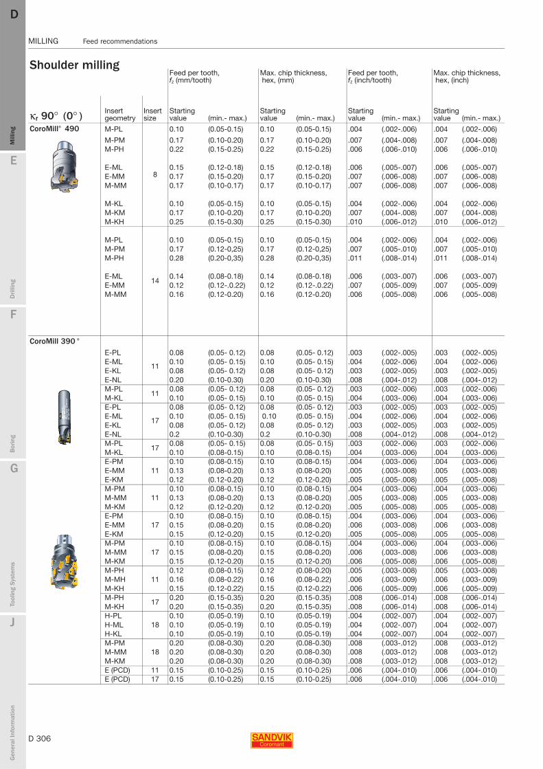
D 306
MILLING Feed recommendations
E
Mill
ing
Drilli
ng
F
Bor
ing
G
Tool
ing
Syst
ems
J
Gen
eral
Info
rmat
ion
DDM
illin
g
MILLING Feed recommendations
Shoulder milling Feed per tooth,fz (mm/tooth)
Max. chip thickness, hex, (mm)
Feed per tooth,fz (inch/tooth)
Max. chip thickness, hex, (inch)
κr 90° (0° ) Insert geometry
Insert size
Starting value (min.- max.)
Starting value (min.- max.)
Starting value (min.- max.)
Starting value (min.- max.)
CoroMill® 490 M-PL
8
0.10 (0.05-0.15) 0.10 (0.05-0.15) .004 (.002-.006) .004 (.002-.006)
M-PM 0.17 (0.10-0.20) 0.17 (0.10-0.20) .007 (.004-.008) .007 (.004-.008)M-PH 0.22 (0.15-0.25) 0.22 (0.15-0.25) .006 (.006-.010) .006 (.006-.010)
E-ML 0.15 (0.12-0.18) 0.15 (0.12-0.18) .006 (.005-.007) .006 (.005-.007)E-MM 0.17 (0.15-0.20) 0.17 (0.15-0.20) .007 (.006-.008) .007 (.006-.008) M-MM 0.17 (0.10-0.17) 0.17 (0.10-0.17) .007 (.006-.008) .007 (.006-.008)
M-KL 0.10 (0.05-0.15) 0.10 (0.05-0.15) .004 (.002-.006) .004 (.002-.006)M-KM 0.17 (0.10-0.20) 0.17 (0.10-0.20) .007 (.004-.008) .007 (.004-.008)M-KH 0.25 (0.15-0.30) 0.25 (0.15-0.30) .010 (.006-.012) .010 (.006-.012)
14
M-PL 0.10 (0.05-0.15) 0.10 (0.05-0.15) .004 (.002-.006) .004 (.002-.006)M-PM 0.17 (0.12-0,25) 0.17 (0.12-0,25) .007 (.005-.010) .007 (.005-.010)M-PH 0.28 (0.20-0,35) 0.28 (0.20-0,35) .011 (.008-.014) .011 (.008-.014)
E-ML 0.14 (0.08-0.18) 0.14 (0.08-0.18) .006 (.003-.007) .006 (.003-.007)E-MM 0.12 (0.12-.0.22) 0.12 (0.12-.0.22) .007 (.005-.009) .007 (.005-.009)M-MM 0.16 (0.12-0.20) 0.16 (0.12-0.20) .006 (.005-.008) .006 (.005-.008)
CoroMill 390 ®
E-PL
11
0.08 (0.05- 0.12) 0.08 (0.05- 0.12) .003 (.002-.005) .003 (.002-.005)E-ML 0.10 (0.05- 0.15) 0.10 (0.05- 0.15) .004 (.002-.006) .004 (.002-.006)E-KL 0.08 (0.05- 0.12) 0.08 (0.05- 0.12) .003 (.002-.005) .003 (.002-.005)E-NL 0.20 (0.10-0.30) 0.20 (0.10-0.30) .008 (.004-.012) .008 (.004-.012)M-PL
110.08 (0.05- 0.12) 0.08 (0.05- 0.12) .003 (.002-.006) .003 (.002-.006)
M-KL 0.10 (0.05- 0.15) 0.10 (0.05- 0.15) .004 (.003-.006) .004 (.003-.006)E-PL
17
0.08 (0.05- 0.12) 0.08 (0.05- 0.12) .003 (.002-.005) .003 (.002-.005)E-ML 0.10 (0.05- 0.15) 0.10 (0.05- 0.15) .004 (.002-.006) .004 (.002-.006) E-KL 0.08 (0.05- 0.12) 0.08 (0.05- 0.12) .003 (.002-.005) .003 (.002-.005) E-NL 0.2 (0.10-0.30) 0.2 (0.10-0.30) .008 (.004-.012) .008 (.004-.012)M-PL
170.08 (0.05- 0.15) 0.08 (0.05- 0.15) .003 (.002-.006) .003 (.002-.006)
M-KL 0.10 (0.08-0.15) 0.10 (0.08-0.15) .004 (.003-.006) .004 (.003-.006)E-PM
110.10 (0.08-0.15) 0.10 (0.08-0.15) .004 (.003-.006) .004 (.003-.006)
E-MM 0.13 (0.08-0.20) 0.13 (0.08-0.20) .005 (.003-.008) .005 (.003-.008)E-KM 0.12 (0.12-0.20) 0.12 (0.12-0.20) .005 (.005-.008) .005 (.005-.008)M-PM
110.10 (0.08-0.15) 0.10 (0.08-0.15) .004 (.003-.006) .004 (.003-.006)
M-MM 0.13 (0.08-0.20) 0.13 (0.08-0.20) .005 (.003-.008) .005 (.003-.008)M-KM 0.12 (0.12-0.20) 0.12 (0.12-0.20) .005 (.005-.008) .005 (.005-.008)E-PM
170.10 (0.08-0.15) 0.10 (0.08-0.15) .004 (.003-.006) .004 (.003-.006)
E-MM 0.15 (0.08-0.20) 0.15 (0.08-0.20) .006 (.003-.008) .006 (.003-.008)E-KM 0.15 (0.12-0.20) 0.15 (0.12-0.20) .005 (.005-.008) .005 (.005-.008)M-PM
170.10 (0.08-0.15) 0.10 (0.08-0.15) .004 (.003-.006) .004 (.003-.006)
M-MM 0.15 (0.08-0.20) 0.15 (0.08-0.20) .006 (.003-.008) .006 (.003-.008)M-KM 0.15 (0.12-0.20) 0.15 (0.12-0.20) .006 (.005-.008) .006 (.005-.008)M-PH
110.12 (0.08-0.15) 0.12 (0.08-0.20) .005 (.003-.008) .005 (.003-.008)
M-MH 0.16 (0.08-0.22) 0.16 (0.08-0.22) .006 (.003-.009) .006 (.003-.009)M-KH 0.15 (0.12-0.22) 0.15 (0.12-0.22) .006 (.005-.009) .006 (.005-.009)M-PH
170.20 (0.15-0.35) 0.20 (0.15-0.35) .008 (.006-.014) .008 (.006-.014)
M-KH 0.20 (0.15-0.35) 0.20 (0.15-0.35) .008 (.006-.014) .008 (.006-.014)H-PL
180.10 (0.05-0.19) 0.10 (0.05-0.19) .004 (.002-.007) .004 (.002-.007)
H-ML 0.10 (0.05-0.19) 0.10 (0.05-0.19) .004 (.002-.007) .004 (.002-.007)H-KL 0.10 (0.05-0.19) 0.10 (0.05-0.19) .004 (.002-.007) .004 (.002-.007)M-PM
180.20 (0.08-0.30) 0.20 (0.08-0.30) .008 (.003-.012) .008 (.003-.012)
M-MM 0.20 (0.08-0.30) 0.20 (0.08-0.30) .008 (.003-.012) .008 (.003-.012)M-KM 0.20 (0.08-0.30) 0.20 (0.08-0.30) .008 (.003-.012) .008 (.003-.012)E (PCD) 11 0.15 (0.10-0.25) 0.15 (0.10-0.25) .006 (.004-.010) .006 (.004-.010)E (PCD) 17 0.15 (0.10-0.25) 0.15 (0.10-0.25) .006 (.004-.010) .006 (.004-.010)
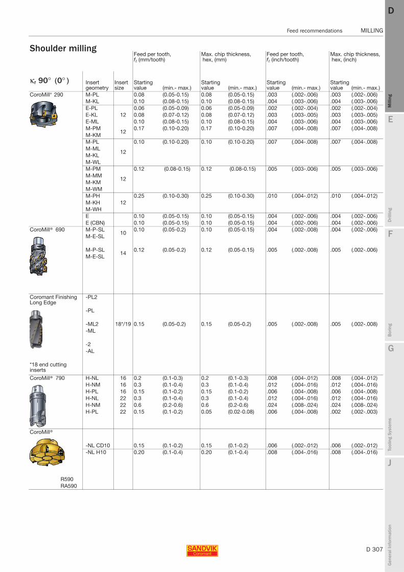
E
D 307
Mill
ing
Drilli
ng
F
Bor
ing
G
Tool
ing
Syst
ems
J
Gen
eral
Info
rmat
ion
DD
Mill
ing
Feed recommendations MILLING
MILLING Feed recommendations
Shoulder milling Feed per tooth,fz (mm/tooth)
Max. chip thickness, hex, (mm)
Feed per tooth,fz (inch/tooth)
Max. chip thickness, hex, (inch)
κr 90° (0° ) Insert geometry
Insert size
Starting value (min.- max.)
Starting value (min.- max.)
Starting value (min.- max.)
Starting value (min.- max.)
CoroMill® 290 M-PL 0.08 (0.05-0.15) 0.08 (0.05-0.15) .003 (.002-.006) .003 (.002-.006)M-KL 0.10 (0.08-0.15) 0.10 (0.08-0.15) .004 (.003-.006) .004 (.003-.006)E-PL
120.06 (0.05-0.09) 0.06 (0.05-0.09) .002 (.002-.004) .002 (.002-.004)
E-KL 0.08 (0.07-0.12) 0.08 (0.07-0.12) .003 (.003-.005) .003 (.003-.005)E-ML 0.10 (0.08-0.15) 0.10 (0.08-0.15) .004 (.003-.006) .004 (.003-.006)M-PM
120.17 (0.10-0.20) 0.17 (0.10-0.20) .007 (.004-.008) .007 (.004-.008)
M-KMM-PL
12
0.10 (0.10-0.20) 0.10 (0.10-0.20) .007 (.004-.008) .007 (.004-.008)M-MLM-KLM-WLM-PM
12
0.12 (0.08-0.15) 0.12 (0.08-0.15) .005 (.003-.006) .005 (.003-.006)M-MMM-KMM-WMM-PH
120.25 (0.10-0.30) 0.25 (0.10-0.30) .010 (.004-.012) .010 (.004-.012)
M-KHM-WHE 0.10 (0.05-0.15) 0.10 (0.05-0.15) .004 (.002-.006) .004 (.002-.006)E (CBN) 0.10 (0.05-0.15) 0.10 (0.05-0.15) .004 (.002-.006) .004 (.002-.006)
CoroMill® 690 M-P-SL10
0.10 (0.05-0.2) 0.10 (0.05-0.15) .004 (.002-.008) .004 (.002-.006)M-E-SL
M-P-SL14
0.12 (0.05-0.2) 0.12 (0.05-0.15) .005 (.002-.008) .005 (.002-.006)M-E-SL
Coromant Finishing Long Edge
-PL2
-PL
-ML2 18*/19 0.15 (0.05-0.2) 0.15 (0.05-0.2) .005 (.002-.008) .005 (.002-.008)-ML
-2-AL
*18 end cutting inserts
CoroMill® 790 H-NL 16 0.2 (0.1-0.3) 0.2 (0.1-0.3) .008 (.004-.012) .008 (.004-.012)H-NM 16 0.3 (0.1-0.4) 0.3 (0.1-0.4) .012 (.004-.016) .012 (.004-.016)H-PL 16 0.15 (0.1-0.2) 0.15 (0.1-0.2) .006 (.004-.008) .006 (.004-.008)H-NL 22 0.3 (0.1-0.4) 0.3 (0.1-0.4) .012 (.004-.016) .012 (.004-.016)H-NM 22 0.6 (0.2-0.6) 0.6 (0.2-0.6) .024 (.008-.024) .024 (.008-.024)H-PL 22 0.15 (0.1-0.2) 0.05 (0.02-0.08) .006 (.004-.008) .002 (.002-.003)
CoroMill®
-NL CD10 0.15 (0.1-0.2) 0.15 (0.1-0.2) .006 (.002-.012) .006 (.002-.012)-NL H10 0.20 (0.1-0.4) 0.20 (0.1-0.4) .008 (.004-.016) .008 (.004-.016)
R590RA590

D 308
MILLING Feed recommendations
E
Mill
ing
Drilli
ng
F
Bor
ing
G
Tool
ing
Syst
ems
J
Gen
eral
Info
rmat
ion
DDM
illin
g
MILLING Feed recommendations
Shoulder milling Feed per tooth,fz (mm/tooth)
Max. chip thickness, hex, (mm)
Feed per tooth,fz (inch/tooth)
Max. chip thickness, hex, (inch)
κr 90° (0° ) Insert geometry
Insert size
Starting value (min.- max.)
Starting value (min.- max.)
Starting value (min.- max.)
Starting value (min.- max.)
AUTO-FS Finishing SBEN 0.17 (0.1-0.3) 0.17 (0.1-0.3) .007 (.004-.012) .007 (.004-.012)
SBEXSBEX-11
R/LA262.4R/L262.4R/L262.42
T-LineRoughing
CDE 0.17 (0.1-0.3) 0.17 (0.1-0.3) .007 (.004-.012) .007 (.004-.012)
R260.90
Face milling Insert geometry
Insert size
Starting value (min. - max.)
Starting value (min.- max.)
Starting value (min. - max.)
Starting value (min. - max.)κr 75° -10°
CoroMill® 345E-PLE-MLE-KL 13 0.15 (0.07-0.20) 0.10 (0.07-0.14) .006 (.003-.008) .004 (.003-.006)M-PLM-KL
M-PMM-MM 0.30 (0.15-0.45) 0.21 (0.10-0.32) .012 (.006-.018) .008 (.004-.013)M-KM
M-PH 0.45 (0.35-0.55) 0.32 (0.25-0.39) .012 (.014-.022) .013 (.010-.015) M-KH 0.40 (0.30-0.50) 0.28 (0.21-0.35) .016 (.012-.020) .011 (.008-.014)
CoroMill® 245 E-PL
0.14 (0.08-0.21) 0.10 (0.06-0.15) .006 (.003-.008) .004 (.002-.006) E-MLE-KL
CT5300.11 (0.07-0.17) 0.08 (0.06-0.12) .004 (.003-.007) .003 (.008-.014) H13A
H10
M-PL 0.17 (0.07-0.21) 0.12 (0.06-0.15) .007 (.003-.008) .005 (.002-.006) M-KLM-PM
0.24 (0.10-0.28) 0.17 (0.07-0.20) .009 (.004-.011) .007 (.003-.008) M-KMCT530
0.12 (0.08-0.18) 0.09 (0.06-0.13) .005 (.003-.007) .004 (.002-.005) H13A
K-MM 0.23 (0.10-0.28) 0.16 (0.07-0.20) .009 (.004-.011) .006 (.003-.008)
M-PH0.35 (0.10-0.42) 0.25
(0.07-0.30).014 (.004-.017) .010 (.003-.030)
M-KH
E-AL 0.24 (0.10-0.28) 0.17 (0.07-0.28) .009 (.004-.011) .010 (.003-.08)
E Ceramic CC6190 0.21 (0.10-0.30) 0.15 (0.07-0.20) .008 (.004-.012) .006 (.003-.008)
E CBN CB50 0.14 (0.07-0.21) 0.10 (0.06-0.15) .006 (.003-.008) .004 (.002-.006)
E PCD CD10 0.14 (0.07-0.21) 0.10 (0.06-0.15) .006 (.003-.008) .004 (.002-.006)

E
D 309
Mill
ing
Drilli
ng
F
Bor
ing
G
Tool
ing
Syst
ems
J
Gen
eral
Info
rmat
ion
DD
Mill
ing
Feed recommendations MILLING
MILLING Feed recommendations
Face and plunge millingFeed per tooth,fz (mm/tooth)
Max. chip thickness, hex, (mm)
Feed per tooth,fz (inch/tooth)
Max. chip thickness, hex, (inch)
κr 75° -10° Insert geometry
Insert size
Starting value (min.- max.)
Starting value (min.- max.)
Starting value (min.- max.)
Starting value (min.- max.)
CoroMill® 365-PL
15
0.20 (0.12-0.28) 0.18 (0.11-0.25) .008 (.005-.011) .008 (.004-.010)-PM 0.22 (0.15-0.28) 0.20 (0.14-0.25) .009 (.005-.011) .008 (.006-.010)-KL 0.22 (0.12-0.35) 0.20 (0.11-0.32) .009 (.004-.011) .008 (.004-.013)-KM 0.25 (0.15-0.35) 0.23 (0.14-0.32) .010 (.006-.014) .009 (.006-.013)
Sandvik AUTO TNHF-WL 0.17 (0.08-0.21) 0.12 (0.06-0.15) .007 (.003-.008) .005 (.002-.006)TNEF-WLTNHF-CA 0.24 (0.1-0.42) 0.17 (0.07-0.30) .009 (.004-.017) .007 (.003-.012)TNEF-CATNHF-65 0.24 (0.1-0.28) 0.17 (0.07-0.20) .009 (.004-.011) .007 (.003-.008)TNEF-65TNJN 0.35 (0.1-0.70) 0.25 (0.07-0.50) .014 (.004-.028) .010 (.003-.020)TNEN 0.24 (0.1-0.28) 0.17 (0.07-0.20) .009 (.004-.011) .007 (.003-.008)TNCN
AUTO-AFN260.8-F 0.15 (0.08-o.20) 0.15 (0.08-o.20) .006 (.003-.008) .006 (.003-.008)N260.8-L
CoroMill® 360PM 19 0.45 (0.30-0.70) 0.40 (0.25-0.60) .018 (.012-.028) .016 (.010-.024)MM 28KH
T-MAX® 45 LNCX -11 0.35 (0.10-1.0) 0.25 (0.07-0.70) .014 (.004-.039) .010 (.003-.028) -12 0.35 (0.10-0.70) 0.25 (0.07-0.50) .014 (.004-.028) .010 (.003-.020)-13 0.35 (0.10-0.70) 0.25 (0.07-0.50) .014 (.004-.028) .010 (.003-.020)
CoroMill® 210 Face milling
Face milling
M-PM 09 1.0 (0.40-2.0) 0.17 (0.07-0.35) 0.039 (.003-.014) .007 (.003-.014)M-KM 14 1.5 (0.5-3.0) 0.26 (0.08-0.52) .059 (.020-.118) .010 (.003-.020)M-MM
Plunge milling
Plunge millingE-PM
E-MM 09 0.15 (0.01-0.2) 0.17 (0.07-0.35) .006 (.001-.008) .007 (.003-.014)E-KM 14 0.20 (0.01-0.25) 0.26 (0.08-0.52) .008 (.001-.008) .010 (.003-.020)
Coromant Plunge Cutter LPMH-PM 25 0.20 (0.10-0.30) .008 (.004-.012)
LPMH-MM

D 310
MILLING Feed recommendations
E
Mill
ing
Drilli
ng
F
Bor
ing
G
Tool
ing
Syst
ems
J
Gen
eral
Info
rmat
ion
DDM
illin
g
MILLING Feed recommendations
Round insert and Ball NoseFeed per tooth,fz
Max. chip thickness, hex, (mm)
Max. chip thickness, hex, (inch)
Insert geometry
Insert size Starting value (min.- max.)
Starting value (min.- max.)mm inch
Round
CoroMill® 200 -PL 10 .375
0.08 (0.05-0.12) .003 (.002-.005)-ML 12 .500-KL 16 .750
20-PM 10 .375
0.17 (0.10-0.20) .007 (.004-.008)-KM 12 .500-MM 16 .750-WM 20-PH 10 .375
0.25 (0.10-0.30) .010 (.002-.012)-KH 12 .500-WH 16 .750
20CBN 12 0.10 (0.05-0.15) .004 (.002-.006)Ceramic 12 , 16 0.20 (0.07-0.30) .008 (.003-0.30)
CoroMill® 300 E-PL 8 0.08 (0.05-0.15) .005 (.002-.006)E-ML 10 0.13 (0.05-0.15) .005 (.002-.006)
12 0.15 (0.05-0.20) .006 (.002-.008)13 0.18 (0.05-0.20) .007 (.002-.008)1620 Face milling round insert (ap <iC/2)
mm.0.20 (0.05-0.25) .008 (.002-.010)
25,4E-PM 5 0.08 (0.05-0.12) .003 (.002-.005)E-MM 7 0.10 (0.05-0.15) .004 (.002-.006)
8 0.13 (0.05-0.20) .005 (.002-.008)9 0.18 (0.05-0.25) .007 (.002-.010)10 0.18 (0.05-0.25) .007 (.002-.010)12 0.18 (0.05-0.25) .007 (.002-.010)13 0.2 (0.05-0.30) .008 (.002-.012)16 0.2 (0.05-0.30) .008 (.002-.012)20 0.25 (0.05-0.40) .010 (.002-.016)
M-PM 8 Side milling (ae<Dcap/2) and round insert (ap<iC/2) mm.
0.13 (0.07-0.20) .005 (.003-.008)M-MM 10 0.15 (0.07-0.25) .006 (.003-.010)
12 0.15 (0.07-0.25) .006 (.003-.010)1316 0.18 (0.07-0.25) .007 (.003-.010)20 0.2 (0.07-0.30) .008 (.003-.012)
25.4M-PH 8 0.15 (0.07-0.25) .006 (.003-.010)M-MH 9 .008 (.003-.012)
10 0.20 (0.07-0.30) .008 (.003-.012)12 0.20 (0.07-0.30) .008 (.003-.012)13 .010 (.003-.016)16 0.25 (0.07-0.40) .014 (.003-.022)20 0.35 (0.07-0.55)
Ball nose
CoroMill Ball noseM-MM 10 .375 .004 (.003-.008)
12 .500 Feed per tooth (mm/tooth), cutter centered
0.10 (0.08-0.21) .004 (.003-.008)16 .625 0.10 (0.08-0.21) .006 (.003-.010)20 .750 0.15 (0.08-0.25) .006 (.003-.010)25 1.00 0.15 (0.08-0.25) .007 (.003-.011)30 0.17 (0.08-0.28)32 1.25 0.17 (0.08-0.28) .008 (.004-.017)40 1.50 0.20 (0.10-0.42) .010 (.004-.017)50 2.00
E-M 10 .375 Feed per tooth (mm/tooth), side milling
0.10 (0.05.-0.21) .004 (.002-0.21)R216 12 .500 0.10 (0.05.-0.21) .004 (.002-0.21)
16 .625 0.10 (0.05.-0.21) .004 (.002-0.21)20 .750 0.15 (0.05.-0.25) .006 (.002-0.25)25 1.00 0.15 (0.05.-0.25) .006 (.002-0.25)30 0.17 (0.05-0.28) .007 (.002-0.25)32 1.25 0.17 (0.05-0.28) .007 (.002-0.25)40 1.5 0.2 (0.05-0.35) .008 (.002-0.25)50 2.00 0.20 (0.05-0.35) .008 (.002-0.25)
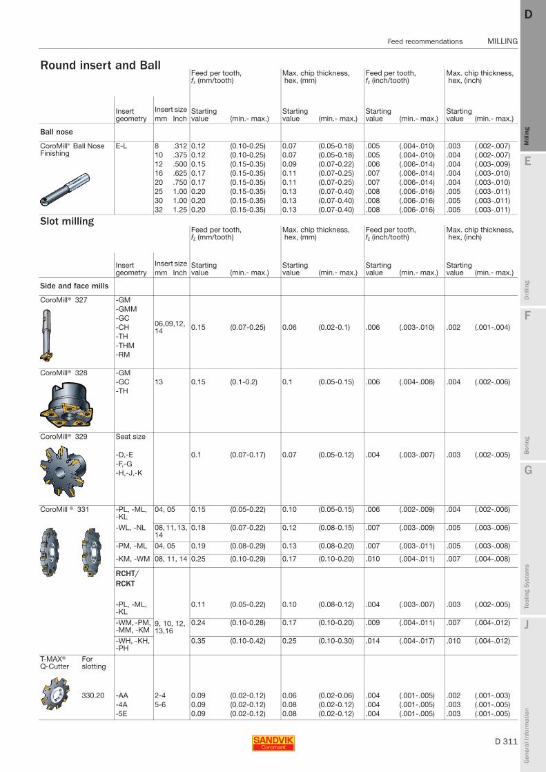
E
D 311
Mill
ing
Drilli
ng
F
Bor
ing
G
Tool
ing
Syst
ems
J
Gen
eral
Info
rmat
ion
DD
Mill
ing
Feed recommendations MILLING
MILLING Feed recommendations
Round insert and Ball Feed per tooth,fz (mm/tooth)
Max. chip thickness, hex, (mm)
Feed per tooth,fz (inch/tooth)
Max. chip thickness, hex, (inch)
Insert geometry
Insert size Starting value (min.- max.)
Starting value (min.- max.)
Starting value (min.- max.)
Starting value (min.- max.)mm Inch
Ball nose
CoroMill® Ball Nose Finishing
E-L 8 .312 0.12 (0.10-0.25) 0.07 (0.05-0.18) .005 (.004-.010) .003 (.002-.007)10 .375 0.12 (0.10-0.25) 0.07 (0.05-0.18) .005 (.004-.010) .004 (.002-.007)12 .500 0.15 (0.15-0.35) 0.09 (0.07-0.22) .006 (.006-.014) .004 (.003-.009)16 .625 0.17 (0.15-0.35) 0.11 (0.07-0.25) .007 (.006-.014) .004 (.003-.010)20 .750 0.17 (0.15-0.35) 0.11 (0.07-0.25) .007 (.006-.014) .004 (.003-.010)25 1.00 0.20 (0.15-0.35) 0.13 (0.07-0.40) .008 (.006-.016) .005 (.003-.011)30 1.00 0.20 (0.15-0.35) 0.13 (0.07-0.40) .008 (.006-.016) .005 (.003-.011)32 1.25 0.20 (0.15-0.35) 0.13 (0.07-0.40) .008 (.006-.016) .005 (.003-.011)
Slot millingFeed per tooth,fz (mm/tooth)
Max. chip thickness, hex, (mm)
Feed per tooth,fz (inch/tooth)
Max. chip thickness, hex, (inch)
Insert geometry
Insert size Starting value (min.- max.)
Starting value (min.- max.)
Starting value (min.- max.)
Starting value (min.- max.)mm Inch
Side and face mills
CoroMill® 327 -GM
06,09,12,14 0.15 (0.07-0.25) 0.06 (0.02-0.1) .006 (.003-.010) .002 (.001-.004)
-GMM-GC-CH-TH-THM-RM
CoroMill® 328 -GM13 0.15 (0.1-0.2) 0.1 (0.05-0.15) .006 (.004-.008) .004 (.002-.006)-GC
-TH
CoroMill® 329 Seat size
-D,-E 0.1 (0.07-0.17) 0.07 (0.05-0.12) .004 (.003-.007) .003 (.002-.005)-F,-G-H,-J,-K
CoroMill ® 331 -PL, -ML, -KL
04, 05 0.15 (0.05-0.22) 0.10 (0.05-0.15) .006 (.002-.009) .004 (.002-.006)
-WL, -NL 08, 11, 13, 14
0.18 (0.07-0.22) 0.12 (0.08-0.15) .007 (.003-.009) .005 (.003-.006)
-PM, -ML 04, 05 0.19 (0.08-0.29) 0.13 (0.08-0.20) .007 (.003-.011) .005 (.003-.008)
-KM, -WM 08, 11, 14 0.25 (0.10-0.29) 0.17 (0.10-0.20) .010 (.004-.011) .007 (.004-.008)
RCHT/RCKT
-PL, -ML, -KL
9, 10, 12, 13,16
0.11 (0.05-0.22) 0.10 (0.08-0.12) .004 (.003-.007) .003 (.002-.005)
-WM, -PM, -MM, -KM
0.24 (0.10-0.28) 0.17 (0.10-0.20) .009 (.004-.011) .007 (.004-.012)
-WH, -KH, -PH
0.35 (0.10-0.42) 0.25 (0.10-0.30) .014 (.004-.017) .010 (.004-.012)
T-MAX®Q-Cutter
For slotting
330.20 -AA 2-4 0.09 (0.02-0.12) 0.06 (0.02-0.06) .004 (.001-.005) .002 (.001-.003)-4A 5-6 0.09 (0.02-0.12) 0.08 (0.02-0.12) .004 (.001-.005) .003 (.001-.005)-5E 0.09 (0.02-0.12) 0.08 (0.02-0.12) .004 (.001-.005) .003 (.001-.005)

D 312
MILLING Cutting data
E
Mill
ing
Drilli
ng
F
Bor
ing
G
Tool
ing
Syst
ems
J
Gen
eral
Info
rmat
ion
DDM
illin
g
MILLING Cutting data
Milling with large engagement, metric values
ISO P
CMC No. Material
Specific cutting force kc 1
Hardness Brinell
mc
CT530 GC1010Max chip thickness, hex mm
MC No.0.1 – 0.15 – 0.2 0.05 – 0.1 – 0.2
N/mm2 HB Cutting speed vc, m/minSteelUnalloyed
P1.1.Z.AN 01.1 C = 0.1–0.25% 1500 125 0.25 430–390–350 -P1.2.Z.AN 01.2 C = 0.25–0.55% 1600 150 0.25 385–350–315 -P1.3.Z.AN 01.3 C = 0.55–0.80% 1700 170 0.25 365–330–300 -P1.3.Z.AN 01.4 1800 210 0.25 315–290–260 -P1.3.Z.HT 01.5 2000 300 0.25 235–210–195 -
Low alloyed (alloying elements ≤ 5%)P2.1.Z.AN 02.1 Non-hardened 1700 175 0.25 300–275–245 -P2.5.Z.HT 02.2 Hardened and tempered 1900 300 0.25 195–180–160 -
High alloyed (alloying elements > 5%)P3.0.Z.AN 03.11 Annealed 1950 200 0.25 230–205–185 180-165-135P3.1.Z.AN 03.13 Hardened tool steel 2150 200 0.25 190–170–155 150-135-110P3.0.Z.HT 03.21 2900 300 0.25 165–150–135 130-120-100P3.0.Z.HT 03.22 3100 380 0.25 105–95–85 80-75-60
CastingsP1.5.C.UT 06.1 Unalloyed 1400 150 0.25 305–280–250 245-220-180P2.6.C.UT 06.2 Low alloyed (alloying elements ≤ 5%) 1600 200 0.25 245–220–200 195-175-145P3.0.C.UT 06.3 High alloyed (alloying elements > 5%) 1950 200 0.25 180–160–145 140-130-105
ISO M
CMC No. Material
Specific cutting force kc 1
Hardness Brinell
mc
CT530 GC1025Max chip thickness, hex mm
MC No.0.1 – 0.15 – 0.2 0.05 – 0.1 – 0.2
N/mm2 HB Cutting speed vc, m/minStainless steel Ferritic/martensitic
P5.0.Z.AN 05.11 Non-hardened 1800 200 0.21 285 –255 –230 255 –225 –180P5.0.Z.PH 05.12 PH-hardened 2850 330 0.21 205 –185 –165 180 –160 –130P5.0.Z.HT 05.13 Hardened 2350 330 0.21 215 –190 –170 185 –165 –135
AusteniticM1.0.Z.AQ 05.21 Non-hardened 1950 200 0.21 265 –240 –215 250 –225 –180M1.0.Z.PH 05.22 PH-hardened 2850 330 0.21 200 –175 –160 170 –155 –125M2.0.Z.AQ 05.23 Super austenitic 2250 200 – –
Austenitic-ferritic (Duplex)M3.1.Z.AQ 05.51 Non-weldable ≥ 0.05%C 2000 230 0.21 260 –235 –210 205 –185 –145M3.2.Z.AQ 05.52 Weldable < 0.05%C 2450 260 0.21 230 –205 –185 175 –155 –125
Stainless steel – CastFerritic/martensitic
P5.0.C.UT 15.11 Non-hardened 1700 200 0.25 255 –230 –205 225 –200 –160P5.0.C.PH 15.12 PH-hardened 2450 330 0.25 180 –160 –145 155 –140 –115P5.0.C.HT 15.13 Hardened 2150 330 0.25 195 –175 –155 170 –155 –120M1.0.C.UT 15.21 Non hardened 1800 200 0.25 255 –225 –205 235 –210 –170M1.0C.PH 15.22 PH-hardened 2450 330 0.25 180 –160 –145 160 –140 –115M2.0.C.AQ 15.23 Super austenitic 2150 200 – –
Austenitic-ferritic (Duplex)M3.1.C.AQ 15.51 Non-weldable ≥ 0.05%C 1800 230 0.25 245 –220 –195 195 –175 –140M3.2.C.AQ 15.52 Weldable < 0.05%C 2250 260 0.25 215 –190 –170 160 –145 –115
ISO K
CMC No. Material
Specific cutting force kc 1
Hardness Brinell
mc
CB50 CC6190Max chip thickness, hex mm
MC No.0.1 – 0.15 – 0.2 0.1 – 0.2 – 0.3
N/mm2 HB Cutting speed vc, m/minMalleable cast iron
07.1 Ferritic (short chipping) 790 130 0.28 - 1300 –1050 –880K1.1.C.NS 07.2 Pearlitic (long chipping) 900 230 0.28 - 1100 –890 –730
Grey cast ironK2.1.C.UT 08.1 Low tensile strength 890 180 0.28 850 –720 –620 1600–1300–1050K2.2.C.UT 08.2 High tensile strength 1100 245 0.28 910 –780 –670 1200–990–810
Nodular cast iron K3.1.C.UT 09.1 Ferritic 900 160 0.28 - 1000–830–680K3.3.C.UT 09.2 Pearlitic 1350 250 0.28 495 –420 –360 840 –690 –570
Conditions:
100 mm 125 mmCutter, dia. 125 mm, centred over the workpiece. Working engagement 100 mm.

E
D 313
Mill
ing
Drilli
ng
F
Bor
ing
G
Tool
ing
Syst
ems
J
Gen
eral
Info
rmat
ion
DD
Mill
ing
Cutting data MILLING
MILLING Cutting data
GC1025 GC1030 GC4220 GC4230 GC4240 GC3040 GC2030 GC2040 SM30Max chip thickness, hex mm
0.05−0.1−0.2 0.05−0.1−0.2 0.1– 0.2–0.3 0.1– 0.2–0.3 0.1-0.2-0.3 0.1–0.2–0.3 0.1–0.2–0.4 0.1–0.2–0.4 0.1–0.2–0.4Cutting speed vc, m/min
340-310-255 375−340−280 490−405−330 400−330−270 340-280-230 390 –320 –260 295−240−165 295 –240 –165 265 –230 –170305-280-230 335−305−250 440−360−295 360−295−245 305-250-205 350 –285 –235 265−215−145 265 –215 –145 240 –205 –150290-260-215 320−290−235 415−340−280 340−280−230 290-235-195 330 –270 –220 250−205−135 250 –205 –135 225 –195 –145250-230-185 275−250−205 365−300−245 295−245−200 250-205-170 290 –235 –195 220−180−120 220 –180 –120 195 –170 –125185-170-140 205−185−155 270−220−180 220−180−150 185-155-125 215 –175 –145 160−130−90 160 –130 –90 145 –125 –90
280-255-210 265−240−195 345−285−230 280−230−190 240-195-160 275 –225 –185 205−170−115 205 –170 –115 185 –160 –120155-140-115 170−155−130 225−185−150 185−150−125 155-130-105 180 –145 –120 135−110−75 135 –110 –75 120 –105 –75
180-165-135 180−165−135 300−245−200 195−160−130 165-135-110 205 –170 –140 155−130−85 155 –130 –85 140 –120 –90150−135−110 150−135−110 215−180−145 160−130−110 135-110-90 170 –140 –115 125−105−70 125 –105 –70 115 –100 –75130−120−100 130−120−100 190−155−125 140−115−95 120-100-80 150 –125 –100 110-90−60 110 –90 –60 105 –90 –65
80−75−60 80−75−60 120−95−80 85−70−60 75-60-50 95 –75 –65 70−55−38 70 –55 –38 65 –55 –41
245−220−180 245−220−180 350−290−235 260−215−175 220-180-150 280 –230 –190 210−170−115 210 –170 –115 190 –165 –120195−175−145 195−175−145 280−230−190 205−170−140 175-145-120 220 –180 –150 170−140−95 170 –140 –95 150 –130 –95140−130−105 140−130−105 205−170−140 150−125−100 130-105-85 160 –135 –110 120−100−70 120 –100 –70 110 –95 –70
GC1030 1040 S30T S40T GC2030 GC2040 GC4230 GC4240 SM30Max chip thickness, hex mm
0.05-0.1-0,2 0.05-0.15-0.25 0.05-0.15-0.25 0.1-0.2-0.3 0.05 – 0.15 – 0.25 0.1 – 0.2 – 0.3 0.1 – 0.2 – 0.3 0.1-0.2-0.4 0.1 – 0.2 – 0.4Cutting speed vc, m/min
255 –225 –180 185 – 140 – 105 255 – 190 – 140 250 – 200 – 160 240 –190 –155 240 –190 –155 275 –220 –175 210 –170 –110 185 –160 –115180 –160 –130 130 – 100 – 70 180 – 135 – 100 170 – 135 – 110 170 –135 –110 165 –130 –105 190 –150 –120 140 –110 –70 105 –90 –65185 –165 –135 135 – 100 – 75 185 – 140 – 105 180 – 145 – 115 175 –140 –115 175 –140 –110 200 –160 –125 160 –125 –80 110 –95 –70
250 –225 –180 180 – 135 – 100 250 – 185 – 140 210 – 165 – 135 235 –190 –150 200 –160 –130 - 185 –150 –95 170 –150 –110170 –155 –125 125 – 95 – 70 170 – 130 – 95 165 – 130 – 105 165 –130 –105 160 –125 –100 - 135 –105 –70 100 –85 –65
– 125 – 90 – 70 170 – 125 – 95 145 – 115 – 95 – – – – –
205 –185 –145 150 – 115 – 85 205 – 155 – 115 175 – 140 – 110 195 –155 –125 170 –135 –105 - 170 –135 –85 100 –85 –65175 –155 –125 125 – 95 – 70 175 – 130 – 95 140 – 115 – 90 165 –130 –105 135 –110 –85 - 135 –110 –70 130 –110 –80
225 –200 –160 165 – 125 – 90 225 – 165 – 125 220 – 175 – 140 215 –170 –135 210 –170 –135 245 –195 –155 185 –150 –95 165 –145 –105155 –140 –115 115 – 85 – 65 155 – 115 – 85 150 – 120 – 95 150 –120 –95 145 –115 –90 165 –130 –105 120 –100 –65 90 –80 –60170 –155 –120 125 – 90 – 70 170 – 125 – 95 165 – 135 – 105 160 –130 –105 160 –130 –100 180 –145 –115 145 –115 –75 100 –85 –65235 –210 –170 175 – 130 – 95 235 – 175 – 130 200 – 160 – 130 225 –180 –145 190 –155 –125 - 180 –140 –90 165 –140 –105160 –140 –115 115 – 85 – 65 160 – 115 – 85 150 – 120 – 95 150 –120 –95 145 –115 –90 - 125 –100 –65 90 –80 –60
– 110 – 85 – 60 155 – 115 – 85 130 – 105 – 85 – – – – –195 –175 –140 145 – 105 – 80 195 – 15 – 110 165 – 130 – 105 185 –150 –120 160 –125 –100 - 160 –125 –80 160 –135 –100160 –145 –115 115 – 85 – 65 160 – 120 – 90 135 – 105 – 85 150 –120 –95 130 –100 –80 - 125 –100 –65 120 –105 –75
GC3220 GC3040 K20W GC4220 GC4230 GC1020 H13A K20DMax chip thickness, hex mm
0.1 – 0.2 – 0.3 0.1 – 0.2 – 0.4 0.1 – 0.2 – 0.3 0.1 – 0.2 – 0.3 0.1 – 0.2 – 0.3 0.1 – 0.2 – 0.3 0.1 – 0.2 – 0.4 0.1-0.2-0.3Cutting speed vc, m/min
305–250–205 240–195–135 255–210–170 255 –210 –170 215 –175 –145 295–240–200 120–105–75 265-220-180255–210–170 200–165–110 210–170–140 210 –170 –140 175 –145 –120 240–195– 160 100– 85–65 220-180-150
335–275–225 260–215–145 290–240–195 275 –225 –185 230 –190 –155 335–275–225 130–110–85 290-240-195270–220–180 210–170–115 220–180–150 220 –180 –150 185 –155 –125 255–210–170 105– 90–65 235-190-155
210–170–140 165–135–90 175–140–115 175 –140 –115 145 –120 –100 200–165–135 80– 70–50 180-150-125195–160–130 150–125–85 160–130–110 160 –130 –110 135 –110 –90 185–150–125 75– 65–50 170-140-115
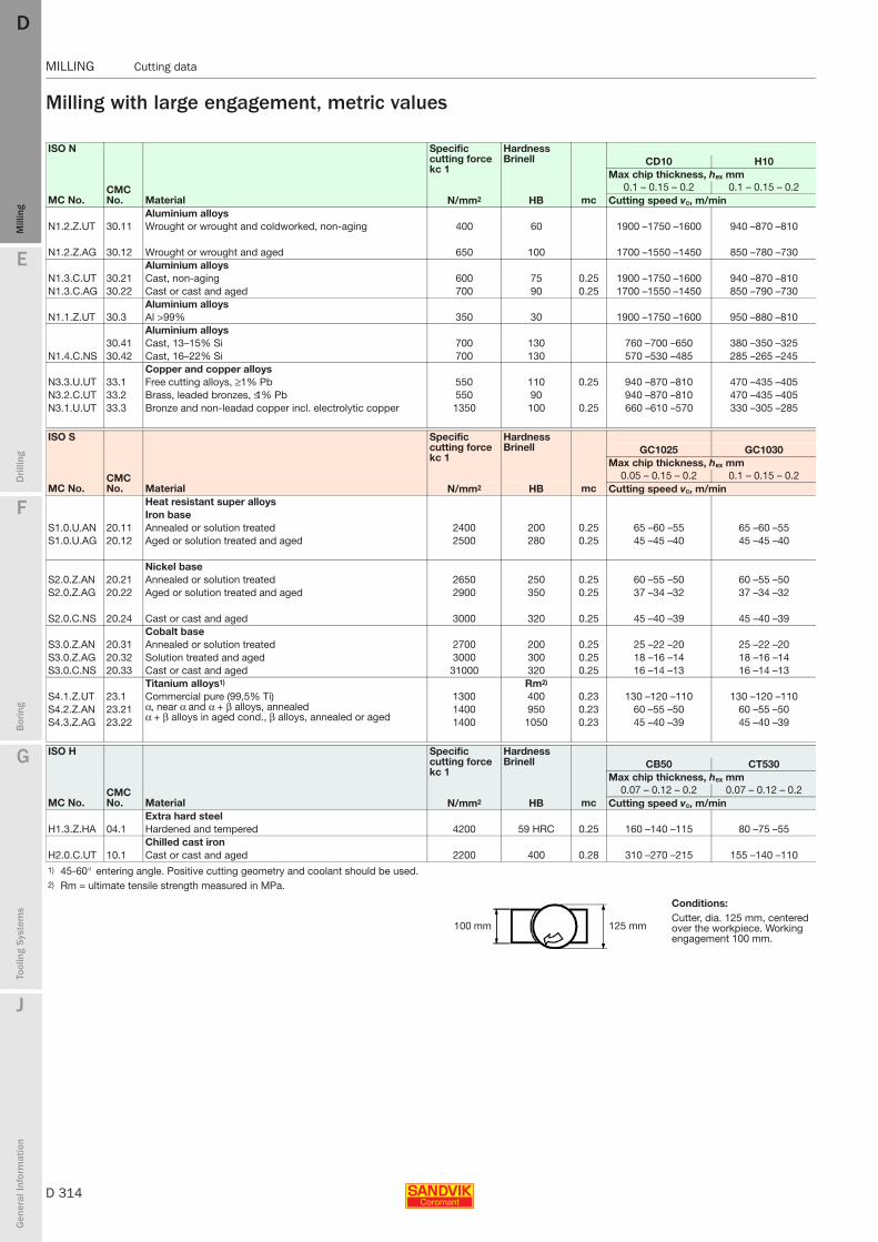
D 314
MILLING Cutting data
E
Mill
ing
Drilli
ng
F
Bor
ing
G
Tool
ing
Syst
ems
J
Gen
eral
Info
rmat
ion
DDM
illin
g
MILLING Cutting data
Milling with large engagement, metric values
ISO N
CMC No. Material
Specific cutting force kc 1
Hardness Brinell
mc
CD10 H10Max chip thickness, hex mm
MC No.0.1 – 0.15 – 0.2 0.1 – 0.15 – 0.2
N/mm2 HB Cutting speed vc, m/minAluminium alloys
N1.2.Z.UT 30.11 Wrought or wrought and coldworked, non-aging 400 60 1900 –1750 –1600 940 –870 –810
N1.2.Z.AG 30.12 Wrought or wrought and aged 650 100 1700 –1550 –1450 850 –780 –730Aluminium alloys
N1.3.C.UT 30.21 Cast, non-aging 600 75 0.25 1900 –1750 –1600 940 –870 –810N1.3.C.AG 30.22 Cast or cast and aged 700 90 0.25 1700 –1550 –1450 850 –790 –730
Aluminium alloys N1.1.Z.UT 30.3 Al >99% 350 30 1900 –1750 –1600 950 –880 –810
Aluminium alloys 30.41 Cast, 13–15% Si 700 130 760 –700 –650 380 –350 –325
N1.4.C.NS 30.42 Cast, 16–22% Si 700 130 570 –530 –485 285 –265 –245Copper and copper alloys
N3.3.U.UT 33.1 Free cutting alloys, ≥1% Pb 550 110 0.25 940 –870 –810 470 –435 –405N3.2.C.UT 33.2 Brass, leaded bronzes, ≤1% Pb 550 90 940 –870 –810 470 –435 –405N3.1.U.UT 33.3 Bronze and non-leadad copper incl. electrolytic copper 1350 100 0.25 660 –610 –570 330 –305 –285
ISO S
CMC No. Material
Specific cutting force kc 1
Hardness Brinell
mc
GC1025 GC1030Max chip thickness, hex mm
MC No.0.05 – 0.15 – 0.2 0.1 – 0.15 – 0.2
N/mm2 HB Cutting speed vc, m/minHeat resistant super alloysIron base
S1.0.U.AN 20.11 Annealed or solution treated 2400 200 0.25 65 –60 –55 65 –60 –55S1.0.U.AG 20.12 Aged or solution treated and aged 2500 280 0.25 45 –45 –40 45 –45 –40
Nickel baseS2.0.Z.AN 20.21 Annealed or solution treated 2650 250 0.25 60 –55 –50 60 –55 –50S2.0.Z.AG 20.22 Aged or solution treated and aged 2900 350 0.25 37 –34 –32 37 –34 –32
S2.0.C.NS 20.24 Cast or cast and aged 3000 320 0.25 45 –40 –39 45 –40 –39Cobalt base
S3.0.Z.AN 20.31 Annealed or solution treated 2700 200 0.25 25 –22 –20 25 –22 –20S3.0.Z.AG 20.32 Solution treated and aged 3000 300 0.25 18 –16 –14 18 –16 –14S3.0.C.NS 20.33 Cast or cast and aged 31000 320 0.25 16 –14 –13 16 –14 –13
Titanium alloys1) Rm2)
S4.1.Z.UT 23.1 Commercial pure (99,5% Ti) α, near α and α + β alloys, annealed α + β alloys in aged cond., β alloys, annealed or aged
1300 400 0.23 130 –120 –110 130 –120 –110S4.2.Z.AN 23.21 1400 950 0.23 60 –55 –50 60 –55 –50S4.3.Z.AG 23.22 1400 1050 0.23 45 –40 –39 45 –40 –39
ISO H
CMC No. Material
Specific cutting force kc 1
Hardness Brinell
mc
CB50 CT530Max chip thickness, hex mm
MC No.0.07 – 0.12 – 0.2 0.07 – 0.12 – 0.2
N/mm2 HB Cutting speed vc, m/minExtra hard steel
H1.3.Z.HA 04.1 Hardened and tempered 4200 59 HRC 0.25 160 –140 –115 80 –75 –55Chilled cast iron
H2.0.C.UT 10.1 Cast or cast and aged 2200 400 0.28 310 –270 –215 155 –140 –1101) 45-60° entering angle. Positive cutting geometry and coolant should be used.2) Rm = ultimate tensile strength measured in MPa.
Conditions:
100 mm 125 mmCutter, dia. 125 mm, centered over the workpiece. Working engagement 100 mm.
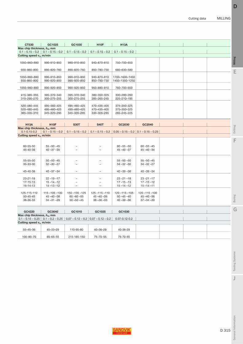
E
D 315
Mill
ing
Drilli
ng
F
Bor
ing
G
Tool
ing
Syst
ems
J
Gen
eral
Info
rmat
ion
DD
Mill
ing
Cutting data MILLING
MILLING Cutting data
CT530 GC1025 GC1030 H10F H13AMax chip thickness, hex mm0.1 – 0.15 – 0.2 0.1 – 0.15 – 0.2 0.1 – 0.15 – 0.2 0.1 – 0.15 – 0.2 0.1 – 0.15 – 0.2
Cutting speed vc, m/min
1050–960–890 990–910–850 990–910–850 940–870–810 750–700–650
930–860–800 890–820–760 890–820–760 850–780–730 680–630–580
1050–960–890 990–910–850 990–910–850 940–870–810 1700–1600–1450930–860–800 990–920–850 990–920–850 850–790–730 1450–1350–1250
1050–960–890 990–920–850 990–920–850 950–880–810 760–700–650
415–385–355 395–370–340 395–370–340 380–350–325 300–280–260310–290–270 300–275–255 300–275–255 285–265–245 225–210–195
520–480–445 495–460–425 495–460–425 470–435–405 375–350–325520–480–445 495–460–425 495–460–425 470–435–405 375–350–325365–335–310 345–320–295 345–320–295 330–305–285 265–245–225
H13A H10F S30T S40T GC2030 GC2040Max chip thickness, hex mm
0.1-0.15-0.2 0.1 – 0.15 – 0.2 0.1 – 0.15 – 0.2 0.1 – 0.15 – 0.2 0.05 – 0.15 – 0.2 0.1 – 0.15 – 0.25Cutting speed vc, m/min
60-55-50 55 –50 –45 – – 60 –55 –50 60 –55 –4545-40-38 40 –37 –35 – – 45 –40 –37 45 –40 –34
55-55-50 50 –50 –45 – – 55 –50 –50 55 –50 –4535-33-30 32 –30 –27 – – 34 –32 –30 34 –32 –27
45-40-38 40 –37 –34 – – 40 –39 –36 40 –39 –34
23-21-18 22 –19 –17 – – 23 –21 –18 23 –21 –1717-15-13 15 –14 –12 – – 17 –15 –13 17 –15 –1216-14-13 14 –13 –12 – – 15 –14 –12 15 –14 –11
125-115-110 115 –105 –100 150 –135 –125 125 –115 –110 120 –115 –105 120 –115 –10050-45-45 45 –40 –38 65 –60 –55 45 –40 –39 50 –45 –40 45 –40 –3638-36-33 34 –31 –29 50 –50 –45 38 –36 –33 40 –39 –36 37 –34 –30
GC4220 GC3040 GC1010 GC1025 GC1030Max chip thickness, hex mm0.1 – 0.15 – 0.25 0.1 – 0.2 – 0.25 0.07 – 0.12 – 0.2 0.07 – 0.12 – 0.2 0.07-0.12-0.2Cutting speed vc, m/min
55–45–36 45–33–29 110-95-80 40–36–29 40-36-29
100–90–70 85–65–55 215-185-150 75–70–55 75-70-55
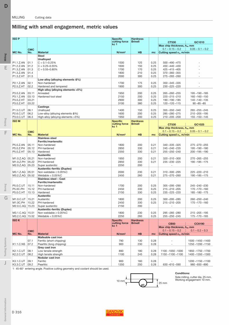
D 316
MILLING Cutting data
E
Mill
ing
Drilli
ng
F
Bor
ing
G
Tool
ing
Syst
ems
J
Gen
eral
Info
rmat
ion
DDM
illin
g
MILLING Cutting data
Milling with small engagement, metric values
ISO P
CMC No. Material
Specific cutting force kc 1
Hardness Brinell
mc
CT530 GC1010Max chip thickness, hex mm
MC No.0.1 – 0.15 – 0.2 0.05 – 0.1 – 0.2
N/mm2 HB Cutting speed vc, m/minSteelUnalloyed
P1.1.Z.AN 01.1 C = 0.1–0.25% 1500 125 0.25 500 –490 –475 -P1.2.Z.AN 01.2 C = 0.25–0.55% 1600 150 0.25 450 –440 –430 -P1.3.Z.AN 01.3 C = 0.55–0.80% 1700 170 0.25 425 –415 –405 -P1.3.Z.AN 01.4 1800 210 0.25 370 –360 –355 -P1.3.Z.HT 01.5 2000 300 0.25 275 –265 –260 -
Low-alloy (alloying elements ≤5%)P2.1.Z.AN 02.1 Non-hardened 1700 175 0.25 350 –345 –335 -P2.5.Z.HT 02.2 Hardened and tempered 1900 300 0.25 230 –225 –220 -
High-alloy (alloying elements >5%)P3.0.Z.AN 03.11 Annealed 1950 200 0.25 265 –260 –255 195 –190 –185P3.1.Z.AN 03.13 Hardened tool steel 2150 200 0.25 220 –215 –210 160 –160 –150P3.0.Z.HT 03.21 2900 300 0.25 190 –190 –185 140 –140 –135P3.0.Z.HT 03.22 3100 380 0.25 120 –120 –115 90 –85 –85
CastingsP1.5.C.UT 06.1 Unalloyed 1400 150 0.25 355 –350 –340 265 –255 –245P2.6.C.UT 06.2 Low-alloy (alloying elements ≤5%) 1600 200 0.25 285 –280 –275 210 –205 –195P3.0.C.UT 06.3 High-alloy (alloying elements >5%) 1950 200 0.25 210 –205 –200 155 –150 –145
ISO M
CMC No. Material
Specific cutting force kc 1
Hardness Brinell
mc
CT530 GC1025Max chip thickness, hex mm
MC No.0.1 – 0.15 – 0.2 0.05 – 0.1 – 0.2
N/mm2 HB Cutting speed vc, m/minStainless steel Ferritic/martensitic
P5.0.Z.AN 05.11 Non-hardened 1800 200 0.21 340 –335 –325 275 –270 –255P5.0.Z.PH 05.12 PH-hardened 2850 330 0.21 245 –240 –235 195 –190 –180P5.0.Z.HT 05.13 Hardened 2350 330 0.21 255 –250 –240 200 –195 –190
AusteniticM1.0.Z.AQ 05.21 Non-hardened 1950 200 0.21 320 –310 –300 270 –265 –255M1.0.Z.PH 05.22 PH-hardened 2850 330 0.21 235 –230 –225 190 –185 –175M2.0.Z.AQ 05.23 Super austenitic 2250 200 - -
Austenitic-ferritic (Duplex)M3.1.Z.AQ 05.51 Non-weldable ≥ 0.05%C 2000 230 0.21 310 –300 –295 225 –220 –210M3.2.Z.AQ 05.52 Weldable < 0.05%C 2450 260 0.21 275 –270 –260 190 –185 –175
Stainless steel – CastFerritic/martensitic
P5.0.C.UT 15.11 Non-hardened 1700 200 0.25 305 –295 –290 245 –240 –230P5.0C.PH 15.12 PH-hardened 2450 330 0.25 215 –210 –205 170 –170 –160P5.0.C.HT 15.13 Hardened 2150 330 0.25 235 –225 –220 185 –180 –175
AusteniticM1.0.C.UT 15.21 Austenitic 1800 200 0.25 300 –295 –285 260 –250 –240M1.0C.PH 15.22 PH-hardened 2450 330 0.25 215 –210 –205 170 –170 –160M2.0.C.AQ 15.23 Super austenitic 2150 200 - -
Austenitic-ferritic (Duplex)M3.1.C.AQ 15.51 Non-weldable ≥ 0.05%C 1800 230 0.25 295 –285 –280 215 –205 –195M3.2.C.AQ 15.52 Weldable < 0.05%C 2250 260 0.25 255 –250 –245 175 –170 –165
ISO K
CMC No. Material
Specific cutting force kc 1
Hardness Brinell
mc
CB50 CC6190Max chip thickness, hex mm
MC No.0.1 – 0.15 – 0.2 0.1 – 0.2 – 0.3
N/mm2 HB Cutting speed vc, m/minMalleable cast iron
07.1 Ferritic (short chipping) 790 130 0.28 - 1500 –1450 –1400K1.1.C.NS 07.2 Pearlitic (long chipping) 900 230 0.28 - 1250 –1200 –1150
Grey cast ironK2.1.C.UT 08.1 Low tensile strength 890 180 0.28 1100 –1050 –1000 1850 –1750 –1700K2.2.C.UT 08.2 High tensile strength 1100 245 0.28 1150 –1100 –1100 1400 –1350 –1300
Nodular cast iron K3.1.C.UT 09.1 Ferritic 900 160 0.28 - 1200 –1150 –1100K3.3.C.UT 09.2 Pearlitic 1350 250 0.28 630 –610 –590 980 –930 –8901) 45-60° entering angle. Positive cutting geometry and coolant should be used.
Conditions:Side milling, cutter dia. 25 mm. Working engagement 10 mm.10 mm
25 mm
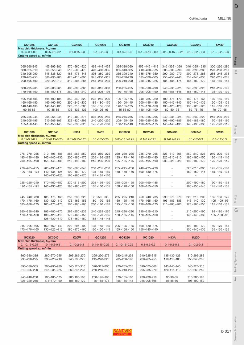
E
D 317
Mill
ing
Drilli
ng
F
Bor
ing
G
Tool
ing
Syst
ems
J
Gen
eral
Info
rmat
ion
DD
Mill
ing
Cutting data MILLING
MILLING Cutting data
GC1025 GC1030 GC4220 GC4230 GC4240 GC3040 GC2030 GC2040 SM30Max chip thickness, hex mm
0.05-0.1-0.2 0.05-0.1-0.2 0.1-0.15-0.3 0.1-0.2-0.3 0.1-0.2-0.3 0.1 – 0.15 – 0.3 0.05 – 0.15 – 0.25 0.1 – 0.2 – 0.3 0.1 – 0.2 – 0.3Cutting speed vc, m/min
365-360-345 405-395-380 570 –560 –520 465 –445 –425 395-380-360 455 –445 – 415 340 –335 – 320 340 –325 – 315 300 –290 –280330-325-310 365-355-340 510 –500 –470 420 –400 –385 355-340-325 410 –400 –375 305 –300 –290 305 –295 –280 270 –260 –250310-305-290 345-335-320 485 –475 –445 395 –380 –360 335-320-310 385 –375 –350 290 –280 –270 290 –275 –265 255 –245 –235270-265-255 300-295-280 425 –415 –390 345 –330 –315 295-280-270 335 –330 –305 255 –250 –240 255 –245 –235 220 –215 –205200-195-190 220-220-210 310 –305 –285 255 –245 –235 220-210-200 250 –245 –225 185 –185 –175 185 –180 –170 165 –160 –155
300-295-285 285-280-265 400 –390 –365 325 –315 –300 280-265-255 320 –310 –290 240 –235 –225 240 –230 –220 210 –205 –195170-165-160 185-180-175 260 –255 –240 215 –205 –195 180-175-165 205 –205 –190 155 –155 –145 155 –150 –145 135 –130 –130
195-190-185 195-190-185 350 –340 –320 225 –215 –205 190-185-175 240 –235 –220 180 –175 –170 180 –175 –165 160 –155 –150160-160-150 160-160-150 250 –245 –230 185 –180 –170 160-150-145 200 –195 –185 150 –145 –140 150 –140 –135 130 –125 –125140-140-135 140-140-135 220 –215 –200 165 –155 –150 140-135-125 175 –170 –160 130 –125 –120 130 –125 –120 115 –110 –110
90-85-85 90-85-85 135 –135 –125 100 –95 –95 85-85-80 110 –105 –100 80 –80 –75 80 –75 –75 70 –70 –65
265-255-245 265-255-245 410 –400 –375 305 –290 –280 255-245-235 325 –315 –295 240 –235 –225 240 –230 –220 215 –205 –200210-205-195 210-205-195 325 –320 –295 240 –230 –220 205-195-190 260 –255 –235 195 –190 –185 195 –185 –180 170 –165 –160155-150-145 155-150-145 240 –235 –220 175 –170 –160 150-145-140 190 –185 –175 145 –140 –135 145 –135 –130 125 –120 –115
GC1030 GC1040 S30T S40T GC2030 GC2040 GC4230 GC4240 SM30Max chip thickness, hex mm
0.05-0.1-0.2 0.05-0.15-0.25 0.05-0.15-0.25 0.1-0.2-0.25 0.05-0.15-0.25 0.1-0.2-0.25 0.1-0.2-0.25 0.1-0.2-0.3 0.1-0.2-0.3Cutting speed vc, m/min
275 –270 –255 210 –195 –185 285 –265 –250 295 –280 –275 260 –250 –235 285 –270 –265 325 –310 –305 250 –240 –225 210 –200 –195195 –190 –180 145 –140 –130 200 –185 –175 205 –195 –275 185 –175 –170 195 –185 –180 225 –215 –210 165 –160 –150 120 –115 –110200 –195 –190 155 –145 –135 210 –195 –180 215 –205 –200 195 –185 –175 205 –195 –190 235 –225 –220 190 –180 –170 125 –120 –115
270 –265 –255 205 –190 –175 280 –260 –245 250 –235 –230 255 –245 –230 240 –225 –220 - 220 –210 –200 195 –185 –180190 –185 –175 140 –135 –125 190 –180 –170 195 –185 –180 180 –170 –160 190 –180 –175 - 160 –150 –145 115 –110 –105
- 140 –130 –120 190 –180 –170 175 –165 –160 - - - - -
225 –220 –210 170 –160 –150 230 –215 –200 205 –195 –190 215 –205 –195 200 –190 –185 - 200 –190 –180 190 –180 –175190 –185 –175 140 –130 –125 195 –180 –170 165 –160 –155 180 –170 –160 160 –155 –150 - 160 –155 –145 145 –140 –135
245 –240 –230 185 –175 –165 250 –235 –220 2 –250 –235 235 –225 –210 250 –240 –235 290 –275 –270 225 –210 –200 185 –180 –175170 –170 –160 130 –120 –110 175 –165 –155 180 –170 –165 160 –155 –145 170 –165 –160 195 –185 –185 145 –140 –130 105 –100 –95185 –180 –175 185 –175 –170 190 –180 –165 200 –190 –185 175 –165 –160 190 –180 –175 215 –205 –200 175 –165 –155 115 –110 –105
260 –250 –240 195 –180 –170 265 –250 –235 240 –225 –220 245 –230 –220 230 –215 –210 - 210 –200 –190 185 –180 –170170 –170 –160 130 –120 –110 175 –165 –155 180 –170 –165 160 –155 –145 170 –165 –160 - 145 –140 –130 105 –100 –95
- 125 –120 –110 175 –160 –150 155 –145 –145 - - - - -
215 –205 –195 160 –150 –140 220 –205 –190 195 –185 –180 205 –195 –185 190 –180 –175 - 190 –180 –170 180 –170 –165175 –170 –165 130 –125 –115 180 –170 –160 160 –150 –145 165 –160 –150 150 –145 –140 - 150 –140 –135 135 –130 –125
GC3220 GC3040 K20W GC4220 GC4230 GC1020 H13A K20DMax chip thickness, hex mm
0.1-0.15-0.25 0.1-0.2-0.3 0.1-0.2-0.3 0.1-0.15-0.25 0.1-0.15-0.25 0.1-0.2-0.3 0.1-0.2-0.3 0.1-0.2-0.3Cutting speed vc, m/min
360–350–335 280–270–255 295-285-270 295–290–275 250–245–235 340-325-315 135-130-125 310-295-285295–290–275 230–220–210 245-235-225 245–240–225 205–200–190 280-265-255 110-110-105 255-245-235
390–380–365 305–290–280 340-325-310 320–315–300 270–265–255 390-375-360 145-140-140 340-325-310310–305–290 245–235–225 260-245-235 260–250–240 215–210–205 295-285-270 120-115-110 270-260-250
245–240–230 190–185–175 200-195-185 200–195–190 170–165–160 230-220-210 95-90-85 210-205-195225–220–215 175–170–160 185-180-170 185–185–175 155–155–145 215-205-195 85-85-80 195-190-180
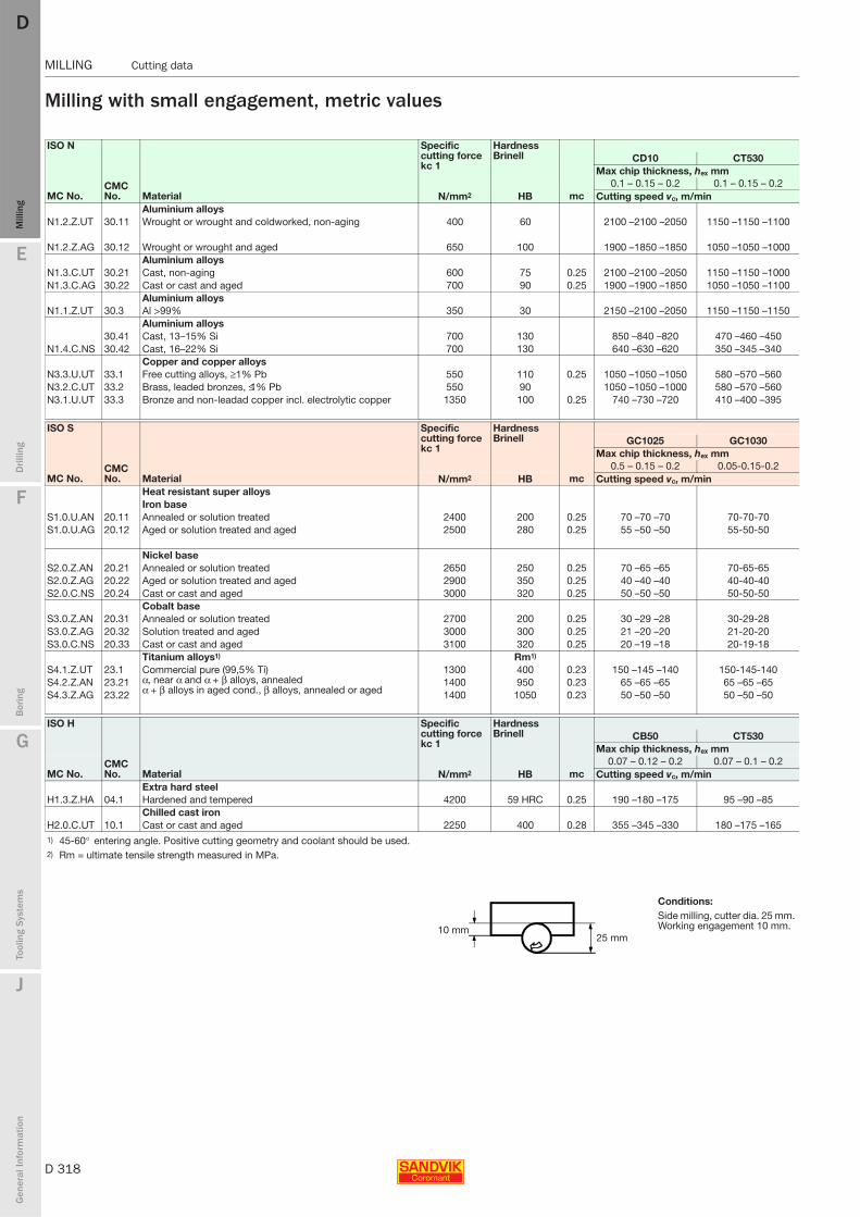
D 318
MILLING Cutting data
E
Mill
ing
Drilli
ng
F
Bor
ing
G
Tool
ing
Syst
ems
J
Gen
eral
Info
rmat
ion
DDM
illin
g
MILLING Cutting data
Milling with small engagement, metric values
ISO N
CMC No. Material
Specific cutting force kc 1
Hardness Brinell
mc
CD10 CT530Max chip thickness, hex mm
MC No.0.1 – 0.15 – 0.2 0.1 – 0.15 – 0.2
N/mm2 HB Cutting speed vc, m/minAluminium alloys
N1.2.Z.UT 30.11 Wrought or wrought and coldworked, non-aging 400 60 2100 –2100 –2050 1150 –1150 –1100
N1.2.Z.AG 30.12 Wrought or wrought and aged 650 100 1900 –1850 –1850 1050 –1050 –1000Aluminium alloys
N1.3.C.UT 30.21 Cast, non-aging 600 75 0.25 2100 –2100 –2050 1150 –1150 –1000N1.3.C.AG 30.22 Cast or cast and aged 700 90 0.25 1900 –1900 –1850 1050 –1050 –1100
Aluminium alloys N1.1.Z.UT 30.3 Al >99% 350 30 2150 –2100 –2050 1150 –1150 –1150
Aluminium alloys 30.41 Cast, 13–15% Si 700 130 850 –840 –820 470 –460 –450
N1.4.C.NS 30.42 Cast, 16–22% Si 700 130 640 –630 –620 350 –345 –340Copper and copper alloys
N3.3.U.UT 33.1 Free cutting alloys, ≥1% Pb 550 110 0.25 1050 –1050 –1050 580 –570 –560N3.2.C.UT 33.2 Brass, leaded bronzes, ≤1% Pb 550 90 1050 –1050 –1000 580 –570 –560N3.1.U.UT 33.3 Bronze and non-leadad copper incl. electrolytic copper 1350 100 0.25 740 –730 –720 410 –400 –395
ISO S
CMC No. Material
Specific cutting force kc 1
Hardness Brinell
mc
GC1025 GC1030Max chip thickness, hex mm
MC No.0.5 – 0.15 – 0.2 0.05-0.15-0.2
N/mm2 HB Cutting speed vc, m/minHeat resistant super alloysIron base
S1.0.U.AN 20.11 Annealed or solution treated 2400 200 0.25 70 –70 –70 70-70-70S1.0.U.AG 20.12 Aged or solution treated and aged 2500 280 0.25 55 –50 –50 55-50-50
Nickel baseS2.0.Z.AN 20.21 Annealed or solution treated 2650 250 0.25 70 –65 –65 70-65-65S2.0.Z.AG 20.22 Aged or solution treated and aged 2900 350 0.25 40 –40 –40 40-40-40S2.0.C.NS 20.24 Cast or cast and aged 3000 320 0.25 50 –50 –50 50-50-50
Cobalt baseS3.0.Z.AN 20.31 Annealed or solution treated 2700 200 0.25 30 –29 –28 30-29-28S3.0.Z.AG 20.32 Solution treated and aged 3000 300 0.25 21 –20 –20 21-20-20S3.0.C.NS 20.33 Cast or cast and aged 3100 320 0.25 20 –19 –18 20-19-18
Titanium alloys1) Rm1)
S4.1.Z.UT 23.1 Commercial pure (99,5% Ti) α, near α and α + β alloys, annealed α + β alloys in aged cond., β alloys, annealed or aged
1300 400 0.23 150 –145 –140 150-145-140S4.2.Z.AN 23.21 1400 950 0.23 65 –65 –65 65 –65 –65S4.3.Z.AG 23.22 1400 1050 0.23 50 –50 –50 50 –50 –50
ISO H
CMC No. Material
Specific cutting force kc 1
Hardness Brinell
mc
CB50 CT530Max chip thickness, hex mm
MC No.0.07 – 0.12 – 0.2 0.07 – 0.1 – 0.2
N/mm2 HB Cutting speed vc, m/minExtra hard steel
H1.3.Z.HA 04.1 Hardened and tempered 4200 59 HRC 0.25 190 –180 –175 95 –90 –85Chilled cast iron
H2.0.C.UT 10.1 Cast or cast and aged 2250 400 0.28 355 –345 –330 180 –175 –1651) 45-60° entering angle. Positive cutting geometry and coolant should be used.2) Rm = ultimate tensile strength measured in MPa.
Conditions:Side milling, cutter dia. 25 mm. Working engagement 10 mm.10 mm
25 mm
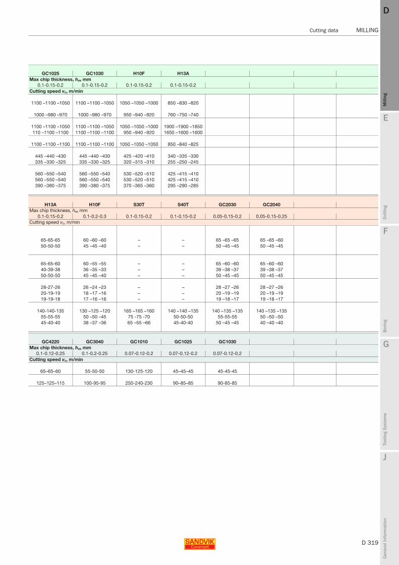
E
D 319
Mill
ing
Drilli
ng
F
Bor
ing
G
Tool
ing
Syst
ems
J
Gen
eral
Info
rmat
ion
DD
Mill
ing
Cutting data MILLING
MILLING Cutting data
GC1025 GC1030 H10F H13AMax chip thickness, hex mm
0.1-0.15-0.2 0.1-0.15-0.2 0.1-0.15-0.2 0.1-0.15-0.2Cutting speed vc, m/min
1100 –1100 –1050 1100 –1100 –1050 1050 –1050 –1000 850 –830 –820
1000 –980 –970 1000 –980 –970 950 –940 –920 760 –750 –740
1100 –1100 –1050 1100 –1100 –1050 1050 –1050 –1000 1900 –1900 –1850110 –1100 –1100 1100 –1100 –1100 950 –940 –920 1650 –1600 –1600
1100 –1100 –1100 1100 –1100 –1100 1050 –1050 –1050 850 –840 –825
445 –440 –430 445 –440 –430 425 –420 –410 340 –335 –330335 –330 –325 335 –330 –325 320 –315 –310 255 –250 –245
560 –550 –540 560 –550 –540 530 –520 –510 425 –415 –410560 –550 –540 560 –550 –540 530 –520 –510 425 –415 –410390 –380 –375 390 –380 –375 370 –365 –360 295 –290 –285
H13A H10F S30T S40T GC2030 GC2040Max chip thickness, hex mm
0.1-0.15-0.2 0.1-0.2-0.3 0.1-0.15-0.2 0.1-0.15-0.2 0.05-0.15-0.2 0.05-0.15-0.25Cutting speed vc, m/min
65-65-65 60 –60 –60 – – 65 –65 –65 65 –65 –6050-50-50 45 –45 –40 – – 50 –45 –45 50 –45 –45
65-65-60 60 –55 –55 – – 65 –60 –60 65 –60 –6040-39-38 36 –35 –33 – – 39 –38 –37 39 –38 –3750-50-50 45 –45 –40 – – 50 –45 –45 50 –45 –45
28-27-26 26 –24 –23 – – 28 –27 –26 28 –27 –2620-19-19 18 –17 –16 – – 20 –19 –19 20 –19 –1919-19-18 17 –16 –16 – – 19 –18 –17 19 –18 –17
140-140-135 130 –125 –120 165 –165 –160 140 –140 –135 140 –135 –135 140 –135 –13555-55-55 50 –50 –45 75 -75 -70 50-50-50 55-55-55 50 –50 –5045-40-40 38 –37 –36 65 –55 –66 45-40-40 50 –45 –45 40 –40 –40
GC4220 GC3040 GC1010 GC1025 GC1030Max chip thickness, hex mm
0.1-0.12-0.25 0.1-0.2-0.25 0.07-0.12-0.2 0.07-0.12-0.2 0.07-0.12-0.2Cutting speed vc, m/min
65–65–60 55-50-50 130-125-120 45–45–45 45-45-45
125–125–115 100-95-95 250-240-230 90–85–85 90-85-85
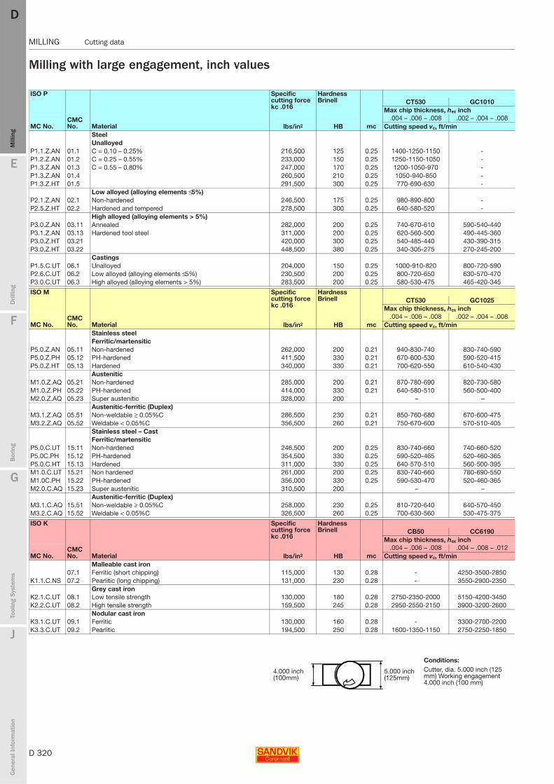
D 320
MILLING Cutting data
E
Mill
ing
Drilli
ng
F
Bor
ing
G
Tool
ing
Syst
ems
J
Gen
eral
Info
rmat
ion
DDM
illin
g
MILLING Cutting data
Milling with large engagement, inch values
ISO P
CMC No. Material
Specific cutting force kc .016
Hardness Brinell
mc
CT530 GC1010Max chip thickness, hex inch
MC No..004 – .006 – .008 .002 – .004 – .008
lbs/in2 HB Cutting speed vc, ft/minSteelUnalloyed
P1.1.Z.AN 01.1 C = 0.10 – 0.25% 216,500 125 0.25 1400-1250-1150 -P1.2.Z.AN 01.2 C = 0.25 – 0.55% 233,000 150 0.25 1250-1150-1050 -P1.3.Z.AN 01.3 C = 0.55 – 0.80% 247,000 170 0.25 1200-1050-970 -P1.3.Z.AN 01.4 260,500 210 0.25 1050-940-850 -P1.3.Z.HT 01.5 291,500 300 0.25 770-690-630 -
Low alloyed (alloying elements ≤ 5%)P2.1.Z.AN 02.1 Non-hardened 246,500 175 0.25 980-890-800 -P2.5.Z.HT 02.2 Hardened and tempered 278,500 300 0.25 640-580-520 -
High alloyed (alloying elements > 5%)P3.0.Z.AN 03.11 Annealed 282,000 200 0.25 740-670-610 590-540-440P3.1.Z.AN 03.13 Hardened tool steel 311,000 200 0.25 620-560-500 490-445-360P3.0.Z.HT 03.21 420,000 300 0.25 540-485-440 430-390-315P3.0.Z.HT 03.22 448,500 380 0.25 340-305-275 270-245-200
CastingsP1.5.C.UT 06.1 Unalloyed 204,000 150 0.25 1000-910-820 800-720-590P2.6.C.UT 06.2 Low alloyed (alloying elements ≤ 5%) 230,500 200 0.25 800-720-650 630-570-470P3.0.C.UT 06.3 High alloyed (alloying elements > 5%) 283,500 200 0.25 580-530-475 465-420-345
ISO M
CMC No. Material
Specific cutting force kc .016
Hardness Brinell
mc
CT530 GC1025Max chip thickness, hex inch
MC No..004 – .006 – .008 .002 – .004 – .008
lbs/in2 HB Cutting speed vc, ft/minStainless steel Ferritic/martensitic
P5.0.Z.AN 05.11 Non-hardened 262,000 200 0.21 940-830-740 830-740-590P5.0.Z.PH 05.12 PH-hardened 411,500 330 0.21 670-600-530 590-520-415P5.0.Z.HT 05.13 Hardened 340,000 330 0.21 700-620-550 610-540-430
AusteniticM1.0.Z.AQ 05.21 Non-hardened 285,000 200 0.21 870-780-690 820-730-580M1.0.Z.PH 05.22 PH-hardened 414,000 330 0.21 640-580-510 560-500-400M2.0.Z.AQ 05.23 Super austenitic 328,000 200 – –
Austenitic-ferritic (Duplex)M3.1.Z.AQ 05.51 Non-weldable ≥ 0.05%C 286,500 230 0.21 850-760-680 670-600-475M3.2.Z.AQ 05.52 Weldable < 0.05%C 356,500 260 0.21 750-670-600 570-510-405
Stainless steel – CastFerritic/martensitic
P5.0.C.UT 15.11 Non-hardened 246,500 200 0.25 830-740-660 740-660-520P5.0C.PH 15.12 PH-hardened 354,500 330 0.25 590-520-465 520-460-365P5.0.C.HT 15.13 Hardened 311,000 330 0.25 640-570-510 560-500-395M1.0.C.UT 15.21 Non hardened 261,000 200 0.25 830-740-660 780-690-550M1.0C.PH 15.22 PH-hardened 356,000 330 0.25 590-530-470 520-460-365M2.0.C.AQ 15.23 Super austenitic 310,500 200 – –
Austenitic-ferritic (Duplex)M3.1.C.AQ 15.51 Non-weldable ≥ 0.05%C 258,000 230 0.25 810-720-640 640-570-450M3.2.C.AQ 15.52 Weldable < 0.05%C 326,500 260 0.25 700-630-560 530-475-375
ISO K
CMC No. Material
Specific cutting force kc .016
Hardness Brinell
mc
CB50 CC6190Max chip thickness, hex inch
MC No..004 – .006 – .008 .004 – .008 – .012
lbs/in2 HB Cutting speed vc, ft/minMalleable cast iron
07.1 Ferritic (short chipping) 115,000 130 0.28 - 4250-3500-2850K1.1.C.NS 07.2 Pearlitic (long chipping) 131,000 230 0.28 - 3550-2900-2350
Grey cast ironK2.1.C.UT 08.1 Low tensile strength 130,000 180 0.28 2750-2350-2000 5150-4200-3450K2.2.C.UT 08.2 High tensile strength 159,500 245 0.28 2950-2550-2150 3900-3200-2600
Nodular cast iron K3.1.C.UT 09.1 Ferritic 130,000 160 0.28 - 3300-2700-2200K3.3.C.UT 09.2 Pearlitic 194,500 250 0.28 1600-1350-1150 2750-2250-1850
Conditions:
4.000 inch (100mm)
5.000 inch (125mm)
Cutter, dia. 5.000 inch (125 mm) Working engagement 4.000 inch (100 mm)
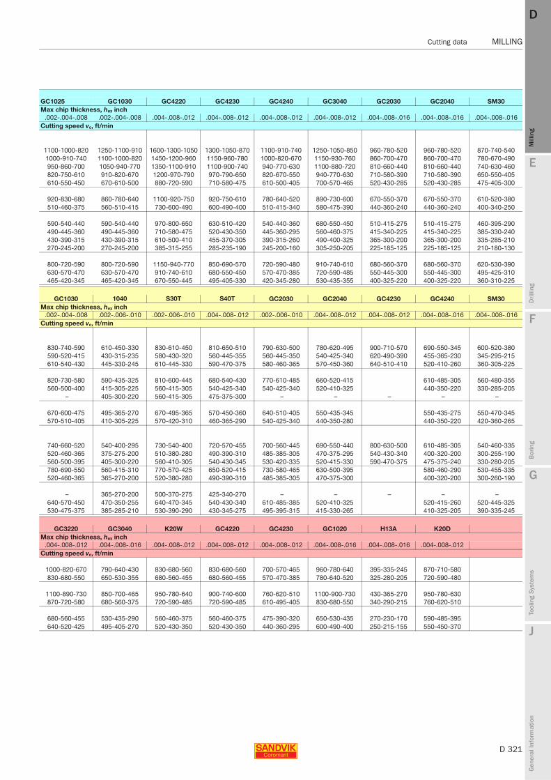
E
D 321
Mill
ing
Drilli
ng
F
Bor
ing
G
Tool
ing
Syst
ems
J
Gen
eral
Info
rmat
ion
DD
Mill
ing
Cutting data MILLING
MILLING Cutting data
GC1025 GC1030 GC4220 GC4230 GC4240 GC3040 GC2030 GC2040 SM30Max chip thickness, hex inch
.002-.004-.008 .002-.004-.008 .004-.008-.012 .004-.008-.012 .004-.008-.012 .004-.008-.012 .004-.008-.016 .004-.008-.016 .004-.008-.016Cutting speed vc, ft/min
1100-1000-820 1250-1100-910 1600-1300-1050 1300-1050-870 1100-910-740 1250-1050-850 960-780-520 960-780-520 870-740-5401000-910-740 1100-1000-820 1450-1200-960 1150-960-780 1000-820-670 1150-930-760 860-700-470 860-700-470 780-670-490950-860-700 1050-940-770 1350-1100-910 1100-900-740 940-770-630 1100-880-720 810-660-440 810-660-440 740-630-460820-750-610 910-820-670 1200-970-790 970-790-650 820-670-550 940-770-630 710-580-390 710-580-390 650-550-405610-550-450 670-610-500 880-720-590 710-580-475 610-500-405 700-570-465 520-430-285 520-430-285 475-405-300
920-830-680 860-780-640 1100-920-750 920-750-610 780-640-520 890-730-600 670-550-370 670-550-370 610-520-380510-460-375 560-510-415 730-600-490 600-490-400 510-415-340 580-475-390 440-360-240 440-360-240 400-340-250
590-540-440 590-540-440 970-800-650 630-510-420 540-440-360 680-550-450 510-415-275 510-415-275 460-395-290490-445-360 490-445-360 710-580-475 520-430-350 445-360-295 560-460-375 415-340-225 415-340-225 385-330-240430-390-315 430-390-315 610-500-410 455-370-305 390-315-260 490-400-325 365-300-200 365-300-200 335-285-210270-245-200 270-245-200 385-315-255 285-235-190 245-200-160 305-250-205 225-185-125 225-185-125 210-180-130
800-720-590 800-720-590 1150-940-770 850-690-570 720-590-480 910-740-610 680-560-370 680-560-370 620-530-390630-570-470 630-570-470 910-740-610 680-550-450 570-470-385 720-590-485 550-445-300 550-445-300 495-425-310465-420-345 465-420-345 670-550-445 495-405-330 420-345-280 530-435-355 400-325-220 400-325-220 360-310-225
GC1030 1040 S30T S40T GC2030 GC2040 GC4230 GC4240 SM30Max chip thickness, hex inch
.002-.004-.008 .002-.006-.010 .002-.006-.010 .004-.008-.012 .002-.006-.010 .004-.008-.012 .004-.008-.012 .004-.008-.016 .004-.008-.016Cutting speed vc, ft/min
830-740-590 610-450-330 830-610-450 810-650-510 790-630-500 780-620-495 900-710-570 690-550-345 600-520-380590-520-415 430-315-235 580-430-320 560-445-355 560-445-350 540-425-340 620-490-390 455-365-230 345-295-215610-540-430 445-330-245 610-445-330 590-470-375 580-460-365 570-450-360 640-510-410 520-410-260 360-305-225
820-730-580 590-435-325 810-600-445 680-540-430 770-610-485 660-520-415 610-485-305 560-480-355560-500-400 415-305-225 560-415-305 540-425-340 540-425-340 520-410-325 440-350-220 330-285-205
– 405-300-220 560-415-305 475-375-300 – – – – –
670-600-475 495-365-270 670-495-365 570-450-360 640-510-405 550-435-345 550-435-275 550-470-345570-510-405 410-305-225 570-420-310 460-365-290 540-425-340 440-350-280 440-350-220 420-360-265
740-660-520 540-400-295 730-540-400 720-570-455 700-560-445 690-550-440 800-630-500 610-485-305 540-460-335520-460-365 375-275-200 510-380-280 490-390-310 485-385-305 470-375-295 540-430-340 400-320-200 300-255-190560-500-395 405-300-220 560-410-305 540-430-345 530-420-335 520-415-330 590-470-375 475-375-240 330-280-205780-690-550 560-415-310 770-570-425 650-520-415 730-580-465 630-500-395 580-460-290 530-455-335520-460-365 365-270-200 520-380-280 490-390-310 485-385-305 470-375-300 400-320-200 300-260-190
– 365-270-200 500-370-275 425-340-270 – – – – –640-570-450 470-350-255 640-470-345 540-430-340 610-485-385 520-410-325 520-415-260 520-445-325530-475-375 385-285-210 530-390-290 430-345-275 495-395-315 415-330-265 410-325-205 390-335-245
GC3220 GC3040 K20W GC4220 GC4230 GC1020 H13A K20DMax chip thickness, hex inch
.004-.008-.012 .004-.008-.016 .004-.008-.012 .004-.008-.012 .004-.008-.012 .004-.008-.016 .004-.008-.016 .004-.008-.012Cutting speed vc, ft/min
1000-820-670 790-640-430 830-680-560 830-680-560 700-570-465 960-780-640 395-335-245 870-710-580830-680-550 650-530-355 680-560-455 680-560-455 570-470-385 780-640-520 325-280-205 720-590-480
1100-890-730 850-700-465 950-780-640 900-740-600 760-620-510 1100-900-730 430-365-270 950-780-630870-720-580 680-560-375 720-590-485 720-590-485 610-495-405 830-680-550 340-290-215 760-620-510
680-560-455 530-435-290 560-460-375 560-460-375 475-390-320 650-530-435 270-230-170 590-485-395640-520-425 495-405-270 520-430-350 520-430-350 440-360-295 600-490-400 250-215-155 550-450-370
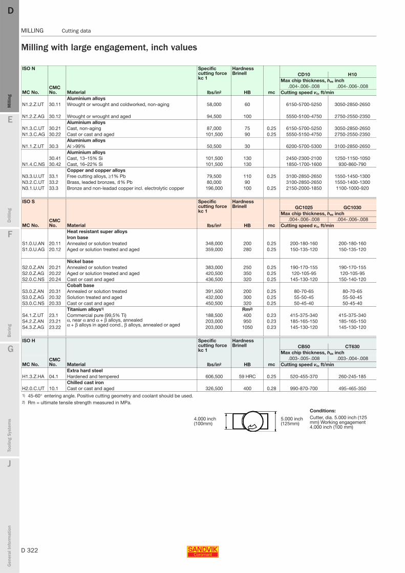
D 322
MILLING Cutting data
E
Mill
ing
Drilli
ng
F
Bor
ing
G
Tool
ing
Syst
ems
J
Gen
eral
Info
rmat
ion
DDM
illin
g
MILLING Cutting data
Milling with large engagement, inch values
ISO N
CMC No. Material
Specific cutting force kc 1
Hardness Brinell
mc
CD10 H10Max chip thickness, hex inch
MC No..004-.006-.008 .004-.006-.008
lbs/in2 HB Cutting speed vc, ft/minAluminium alloys
N1.2.Z.UT 30.11 Wrought or wrought and coldworked, non-aging 58,000 60 6150-5700-5250 3050-2850-2650
N1.2.Z.AG 30.12 Wrought or wrought and aged 94,500 100 5550-5100-4750 2750-2550-2350Aluminium alloys
N1.3.C.UT 30.21 Cast, non-aging 87,000 75 0.25 6150-5700-5250 3050-2850-2650N1.3.C.AG 30.22 Cast or cast and aged 101,500 90 0.25 5550-5150-4750 2750-2550-2350
Aluminium alloys N1.1.Z.UT 30.3 Al >99% 50,500 30 6200-5700-5300 3100-2850-2650
Aluminium alloys 30.41 Cast, 13–15% Si 101,500 130 2450-2300-2100 1250-1150-1050
N1.4.C.NS 30.42 Cast, 16–22% Si 101,500 130 1850-1700-1600 930-860-790Copper and copper alloys
N3.3.U.UT 33.1 Free cutting alloys, ≥1% Pb 79,500 110 0.25 3100-2850-2650 1550-1450-1300N3.2.C.UT 33.2 Brass, leaded bronzes, ≤1% Pb 80,000 90 3100-2850-2650 1550-1400-1300N3.1.U.UT 33.3 Bronze and non-leadad copper incl. electrolytic copper 196,000 100 0.25 2150-2000-1850 1100-1000-920
ISO S
CMC No. Material
Specific cutting force kc 1
Hardness Brinell
mc
GC1025 GC1030Max chip thickness, hex inch
MC No..004-.006-.008 .004-.006-.008
lbs/in2 HB Cutting speed vc, ft/minHeat resistant super alloysIron base
S1.0.U.AN 20.11 Annealed or solution treated 348,000 200 0.25 200-180-160 200-180-160S1.0.U.AG 20.12 Aged or solution treated and aged 359,000 280 0.25 150-135-120 150-135-120
Nickel baseS2.0.Z.AN 20.21 Annealed or solution treated 383,000 250 0.25 190-170-155 190-170-155S2.0.Z.AG 20.22 Aged or solution treated and aged 420,500 350 0.25 120-105-95 120-105-95S2.0.C.NS 20.24 Cast or cast and aged 436,500 320 0.25 145-130-120 150-140-120
Cobalt baseS3.0.Z.AN 20.31 Annealed or solution treated 391,500 200 0.25 80-70-65 80-70-65S3.0.Z.AG 20.32 Solution treated and aged 432,000 300 0.25 55-50-45 55-50-45S3.0.C.NS 20.33 Cast or cast and aged 450,500 320 0.25 50-45-40 50-45-40
Titanium alloys1) Rm2)
S4.1.Z.UT 23.1 Commercial pure (99,5% Ti) α, near α and α + β alloys, annealed α + β alloys in aged cond., β alloys, annealed or aged
188,500 400 0.23 415-375-340 415-375-340S4.2.Z.AN 23.21 203,000 950 0.23 185-165-150 185-165-150S4.3.Z.AG 23.22 203,000 1050 0.23 145-130-120 145-130-120
ISO H
CMC No. Material
Specific cutting force kc 1
Hardness Brinell
mc
CB50 CT630Max chip thickness, hex inch
MC No..003-.005-.008 .003-.004-.008
lbs/in2 HB Cutting speed vc, ft/minExtra hard steel
H1.3.Z.HA 04.1 Hardened and tempered 606,500 59 HRC 0.25 520-455-370 260-245-185Chilled cast iron
H2.0.C.UT 10.1 Cast or cast and aged 326,500 400 0.28 990-870-700 495-465-3501) 45-60° entering angle. Positive cutting geometry and coolant should be used.2) Rm = ultimate tensile strength measured in MPa.
Conditions:
4.000 inch (100mm)
5.000 inch (125mm)
Cutter, dia. 5.000 inch (125 mm) Working engagement 4.000 inch (100 mm)
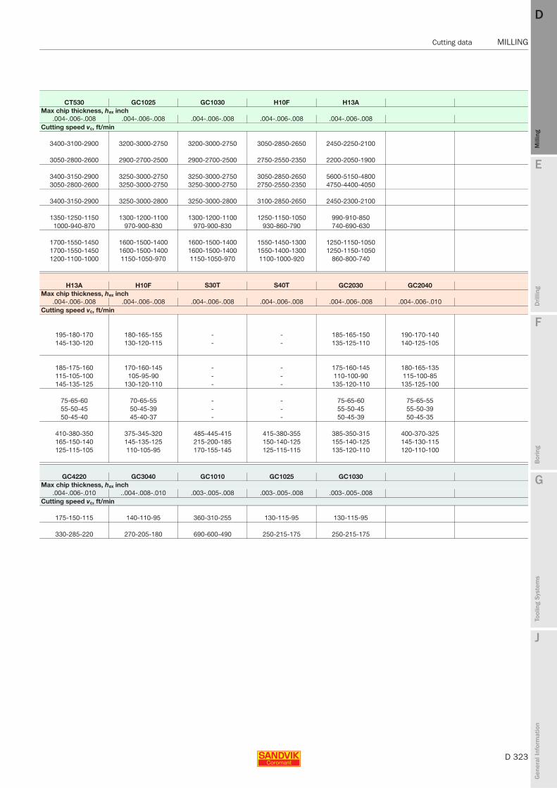
E
D 323
Mill
ing
Drilli
ng
F
Bor
ing
G
Tool
ing
Syst
ems
J
Gen
eral
Info
rmat
ion
DD
Mill
ing
Cutting data MILLING
MILLING Cutting data
CT530 GC1025 GC1030 H10F H13AMax chip thickness, hex inch
.004-.006-.008 .004-.006-.008 .004-.006-.008 .004-.006-.008 .004-.006-.008Cutting speed vc, ft/min
3400-3100-2900 3200-3000-2750 3200-3000-2750 3050-2850-2650 2450-2250-2100
3050-2800-2600 2900-2700-2500 2900-2700-2500 2750-2550-2350 2200-2050-1900
3400-3150-2900 3250-3000-2750 3250-3000-2750 3050-2850-2650 5600-5150-48003050-2800-2600 3250-3000-2750 3250-3000-2750 2750-2550-2350 4750-4400-4050
3400-3150-2900 3250-3000-2800 3250-3000-2800 3100-2850-2650 2450-2300-2100
1350-1250-1150 1300-1200-1100 1300-1200-1100 1250-1150-1050 990-910-8501000-940-870 970-900-830 970-900-830 930-860-790 740-690-630
1700-1550-1450 1600-1500-1400 1600-1500-1400 1550-1450-1300 1250-1150-10501700-1550-1450 1600-1500-1400 1600-1500-1400 1550-1400-1300 1250-1150-10501200-1100-1000 1150-1050-970 1150-1050-970 1100-1000-920 860-800-740
H13A H10F S30T S40T GC2030 GC2040Max chip thickness, hex inch
.004-.006-.008 .004-.006-.008 .004-.006-.008 .004-.006-.008 .004-.006-.008 .004-.006-.010Cutting speed vc, ft/min
195-180-170 180-165-155 - - 185-165-150 190-170-140145-130-120 130-120-115 - - 135-125-110 140-125-105
185-175-160 170-160-145 - - 175-160-145 180-165-135115-105-100 105-95-90 - - 110-100-90 115-100-85145-135-125 130-120-110 - - 135-120-110 135-125-100
75-65-60 70-65-55 - - 75-65-60 75-65-5555-50-45 50-45-39 - - 55-50-45 55-50-3950-45-40 45-40-37 - - 50-45-39 50-45-35
410-380-350 375-345-320 485-445-415 415-380-355 385-350-315 400-370-325165-150-140 145-135-125 215-200-185 150-140-125 155-140-125 145-130-115125-115-105 110-105-95 170-155-145 125-115-115 135-120-110 120-110-100
GC4220 GC3040 GC1010 GC1025 GC1030Max chip thickness, hex inch
.004-.006-.010 ..004-.008-.010 .003-.005-.008 .003-.005-.008 .003-.005-.008Cutting speed vc, ft/min
175-150-115 140-110-95 360-310-255 130-115-95 130-115-95
330-285-220 270-205-180 690-600-490 250-215-175 250-215-175
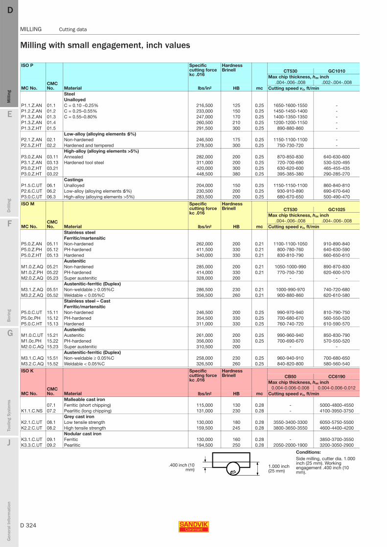
D 324
MILLING Cutting data
E
Mill
ing
Drilli
ng
F
Bor
ing
G
Tool
ing
Syst
ems
J
Gen
eral
Info
rmat
ion
DDM
illin
g
MILLING Cutting data
Milling with small engagement, inch values
ISO P
CMC No. Material
Specific cutting force kc .016
Hardness Brinell
mc
CT530 GC1010Max chip thickness, hex inch
MC No..004-.006-.008 .002-.004-.008
lbs/in2 HB Cutting speed vc, ft/minSteelUnalloyed
P1.1.Z.AN 01.1 C = 0.10 –0.25% 216,500 125 0.25 1650-1600-1550 -P1.2.Z.AN 01.2 C = 0.25–0.55% 233,000 150 0.25 1450-1450-1400 -P1.3.Z.AN 01.3 C = 0.55–0.80% 247,000 170 0.25 1400-1350-1350 -P1.3.Z.AN 01.4 260,500 210 0.25 1200-1200-1150 -P1.3.Z.HT 01.5 291,500 300 0.25 890-880-860 -
Low-alloy (alloying elements ≤5%)P2.1.Z.AN 02.1 Non-hardened 246,500 175 0.25 1150-1100-1100 -P2.5.Z.HT 02.2 Hardened and tempered 278,500 300 0.25 750-730-720 -
High-alloy (alloying elements >5%)P3.0.Z.AN 03.11 Annealed 282,000 200 0.25 870-850-830 640-630-600P3.1.Z.AN 03.13 Hardened tool steel 311,000 200 0.25 720-700-690 530-520-495P3.0.Z.HT 03.21 420,000 300 0.25 630-620-600 465-455-435P3.0.Z.HT 03.22 448,500 380 0.25 395-385-380 290-285-270
CastingsP1.5.C.UT 06.1 Unalloyed 204,000 150 0.25 1150-1150-1100 860-840-810P2.6.C.UT 06.2 Low-alloy (alloying elements ≤5%) 230,500 200 0.25 930-910-890 690-670-640P3.0.C.UT 06.3 High-alloy (alloying elements >5%) 283,500 200 0.25 680-670-650 500-490-470
ISO M
CMC No. Material
Specific cutting force kc .016
Hardness Brinell
mc
CT530 GC1025Max chip thickness, hex inch
MC No..004-.006-.008 .004-.006-.008
lbs/in2 HB Cutting speed vc, ft/minStainless steel Ferritic/martensitic
P5.0.Z.AN 05.11 Non-hardened 262,000 200 0.21 1100-1100-1050 910-890-840P5.0.Z.PH 05.12 PH-hardened 411,500 330 0.21 800-780-760 640-630-590P5.0.Z.HT 05.13 Hardened 340,000 330 0.21 830-810-790 660-650-610
AusteniticM1.0.Z.AQ 05.21 Non-hardened 285,000 200 0.21 1050-1000-990 890-870-830M1.0.Z.PH 05.22 PH-hardened 414,000 330 0.21 770-750-730 620-600-570M2.0.Z.AQ 05.23 Super austenitic 328,000 200 - -
Austenitic-ferritic (Duplex)M3.1.Z.AQ 05.51 Non-weldable ≥ 0.05%C 286,500 230 0.21 1000-990-970 740-720-680M3.2.Z.AQ 05.52 Weldable < 0.05%C 356,500 260 0.21 900-880-860 620-610-580
Stainless steel – CastFerritic/martensitic
P5.0.C.UT 15.11 Non-hardened 246,500 200 0.25 990-970-940 810-790-750P5.0c.PH 15.12 PH-hardened 354,500 330 0.25 700-680-670 560-550-520P5.0.C.HT 15.13 Hardened 311,000 330 0.25 760-740-720 610-590-570
AusteniticM1.0.C.UT 15.21 Austenitic 261,000 200 0.25 990-960-940 850-830-790M1.0c.PH 15.22 PH-hardened 356,000 330 0.25 700-690-670 570-550-520M2.0.C.AQ 15.23 Super austenitic 310,500 200 - -
Austenitic-ferritic (Duplex)M3.1.C.AQ 15.51 Non-weldable ≥ 0.05%C 258,000 230 0.25 960-940-910 700-680-650M3.2.C.AQ 15.52 Weldable < 0.05%C 326,500 260 0.25 840-820-800 580-560-540
ISO K
CMC No. Material
Specific cutting force kc .016
Hardness Brinell
mc
CB50 CC6190Max chip thickness, hex inch
MC No.0.004-0.006-0.008 0.004-0.006-0.012
lbs/in2 HB Cutting speed vc, ft/minMalleable cast iron
07.1 Ferritic (short chipping) 115,000 130 0.28 - 5000-4800-4550K1.1.C.NS 07.2 Pearlitic (long chipping) 131,000 230 0.28 - 4100-3950-3750
Grey cast ironK2.1.C.UT 08.1 Low tensile strength 130,000 180 0.28 3550-3400-3300 6050-5750-5500K2.2.C.UT 08.2 High tensile strength 159,500 245 0.28 3800-3650-3550 4600-4400-4200
Nodular cast iron K3.1.C.UT 09.1 Ferritic 130,000 160 0.28 - 3850-3700-3550K3.3.C.UT 09.2 Pearlitic 194,500 250 0.28 2050-2000-1900 3200-3050-2900
Conditions:Side milling, cutter dia. 1.000 inch (25 mm). Working engagement .400 inch (10 mm).
.400 inch (10mm)
1.000 inch (25 mm)

E
D 325
Mill
ing
Drilli
ng
F
Bor
ing
G
Tool
ing
Syst
ems
J
Gen
eral
Info
rmat
ion
DD
Mill
ing
Cutting data MILLING
MILLING Cutting data
GC1025 GC1030 GC4220 GC4230 GC4240 GC3040 GC2030 GC2040 SM30Max chip thickness, hex inch
.002-.004-.008 .002-.004-.008 .004-.006-.012 .004-.006-.012 .004-.008-.012 .004-.006-.012 .004- .006-.010 .004-.008-.012 .004-.008-.012Cutting speed vc, ft/min
1200-1200-1150 1350-1300-1250 1850-1850-1700 1500-1450-1400 1300-1250-1200 1500-1450-1350 1100-1100-1050 1100-1050-1000 980-950-9101100-1050-1000 1200-1150-1100 1700-1650-1550 1350-1300-1250 1150-1100-1050 1350-1300-1200 1000-990-940 1000-960-920 880-850-8201000-1000-960 1150-1100-1050 1600-1550-1450 1300-1250-1200 1100-1050-1000 1250-1250-1150 950-930-880 950-900-860 830-800-780890-870-830 980-960-920 1400-1350-1250 1150-1100-1050 960-920-880 1100-1050-1000 830-820-780 830-800-760 730-700-680660-650-620 730-710-680 1000-1000-940 840-800-760 710-680-650 810-800-740 610-600-570 610-590-560 540-520-500
990-970-930 930-910-870 1300-1300-1200 1050-1000-980 910-870-830 1050-1000-950 790-770-740 790-750-720 690-660-640550-540-520 610-590-570 860-840-780 700-670-640 590-570-540 680-660-620 510-500-480 510-490-470 450-435-420
640-630-600 640-630-600 1150-1100-1050 740-700-670 630-600-570 790-770-720 590-580-550 590-570-540 520-500-485530-520-495 530-520-495 830-810-760 610-580-560 520-495-475 660-640-600 485-475-450 485-465-440 430-415-405465-455-435 465-455-435 720-700-660 530-510-485 455-435-415 570-560-520 425-415-400 425-405-390 380-365-355290-285-270 290-285-270 450-440-410 335-320-305 285-270-260 360-350-330 265-260-250 265-255-240 235-230-220
860-840-810 860-840-810 1350-1300-1200 990-950-910 840-810-770 1050-1050-970 790-780-740 790-760-730 700-680-650690-670-640 690-670-640 1050-1050-970 790-760-720 670-640-610 850-830-770 640-630-600 640-610-580 560-540-520500-490-470 500-490-470 780-760-710 580-550-530 490-470-450 620-610-570 465-455-435 465-445-425 410-395-380
GC1030 1040 S30T S40T GC2030 GC2040 GC4230 GC4240 SM30Max chip thickness, hex inch
.002-.004-.008 .002-.006-.010 .002-.006.010 .004-.008-.010 .002-.006-.010 .004-.008-.010 .004-.008-.010 .004-.008-.012 .004-.008-.012Cutting speed vc, ft/min
910-890-840 680-640-600 930-870-810 970-920-900 860-820-780 930-890-860 1050-1000-990 820-780-740 680-660-640640-630-590 485-450-420 660-610-570 670-630-620 610-580-550 640-610-590 740-700-680 540-520-490 390-375-360660-650-610 500-470-440 680-540-590 710-670-650 630-600-570 680-640-630 770-730-710 620-590-560 405-390-375
890-870-830 660-640-580 910-850-800 810-770-750 840-800-760 780-740-730 - 730-690-660 630-610-590620-600-570 465-435-405 630-590-550 640-610-590 580-560-530 620-590-570 - 520-500-475 375-360-350
- 455-425-395 630-590-550 570-540-520 - - - - -
740-720-680 560-520-490 750-710-660 680-650-630 700-670-630 650-620-610 - 650-620-590 620-600-580620-610-580 465-435-405 640-600-560 550-520-510 590-560-530 530-500-490 - 530-500-475 475-460-445
810-790-750 610-570-530 830-770-720 860-820-800 770-730-690 830-790-770 950-900-880 730-690-660 610-590-570560-550-520 420-390-365 580-540-500 580-550-540 530-500-475 560-530-520 650-610-600 475-455-430 340-330-315610-590-570 455-425-400 620-580-550 650-620-600 580-550-520 620-590-580 710-670-650 570-540-510 370-360-345
850-830-790 640-590-550 870-810-760 780-740-720 800-760-720 750-710-690 690-660-630 600-580-560570-550-520 420-395-365 580-540-510 590-560-540 530-500-480 560-540-520 480-455-430 340-330-315
- 415-385-360 570-530-495 510-480-470 - - - - -700-680-650 530-495-460 710-670-620 640-610-600 670-630-600 620-590-570 620-590-560 590-570-550580-560-540 430-405-375 590-560-520 520-490-480 540-520-490 495-470-460 490-465-440 440-425-410
GC3220 GC3040 K20W GC4220 GC4230 GC1020 H13A K20DMax chip thickness, hex inch
.004-.006-.010 .004-.008-.012 .004-.008-.012 .004-.006-.010 .004-.006-.010 .004-.008-.012 .004-.008-.012 .004-.008-.012Cutting speed vc, ft/min
1150-1150-1100 920-880-840 970-930-890 970-950-910 810-800-760 1100-1050-1000 445-430-415 1000-970-930970-950-900 760-720-690 800-760-730 800-780-740 670-660-630 920-870-840 365-355-340 840-800-770
1250-1250-1200 1000-950-910 1100-1050-1000 1050-1050-980 890-870-830 1300-1250-1150 485-465-450 1100-1050-10001000-1000-960 800-770-730 840-810-770 840-830-790 710-690-660 970-930-890 385-370-360 890-850-810
800-780-750 630-600-570 660-630-600 660-650-620 560-540-520 760-730-690 305-295-285 690-660-630740-730-700 580-560-530 610-590-560 610-600-570 520-500-480 700-670-640 280-270-260 650-620-590

D 326
MILLING Cutting data
E
Mill
ing
Drilli
ng
F
Bor
ing
G
Tool
ing
Syst
ems
J
Gen
eral
Info
rmat
ion
DDM
illin
g
MILLING Cutting data
Milling with small engagement, inch values
ISO N
CMC No. Material
Specific cutting force kc 1
Hardness Brinell
mc
CD10 CT530Max chip thickness, hex inch
MC No..004-.006-.008 .004-.006-.008
lbs/in2 HB Cutting speed vc, ft/minAluminium alloys
N1.2.Z.UT 30.11 Wrought or wrought and coldworked, non-aging 58,000 60 6950-6800-6700 3800-3750-3700
N1.2.Z.AG 30.12 Wrought or wrought and aged 94,500 100 6250-6150-6050 3450-3400-3300Aluminium alloys
N1.3.C.UT 30.21 Cast, non-aging 87,000 75 0.25 6950-6800-6700 3800-3750-3700N1.3.C.AG 30.22 Cast or cast and aged 101,500 90 0.25 6250-6150-6050 3450-3400-3300
Aluminium alloys N1.1.Z.UT 30.3 Al >99% 50,500 30 7000-6850-6750 3850-3750-3700
Aluminium alloys 30.41 Cast, 13–15% Si 101,500 130 2800-2750-2700 1550-1500-1500
N1.4.C.NS 30.42 Cast, 16–22% Si 101,500 130 2100-2050-2000 1150-1150-1100Copper and copper alloys
N3.3.U.UT 33.1 Free cutting alloys, ≥1% Pb 79,500 110 0.25 3500-3400-3350 1900-1900-1850N3.2.C.UT 33.2 Brass, leaded bronzes, ≤1% Pb 80,000 90 3450-3400-3350 1900-1900-1850N3.1.U.UT 33.3 Bronze and non-leadad copper incl. electrolytic copper 196,000 100 0.25 2450-2400-2350 1350-1300-1300
ISO S
CMC No. Material
Specific cutting force kc 1
Hardness Brinell
mc
GC1025 GC1030Max chip thickness, hex inch
MC No..002-.006-.008 .002-.006-.008
lbs/in2 HB Cutting speed vc, ft/minHeat resistant super alloysIron base
S1.0.U.AN 20.11 Annealed or solution treated 348,000 200 0.25 235-225-225 235-225-225S1.0.U.AG 20.12 Aged or solution treated and aged 359,000 280 0.25 175-170-165 175-170-165
Nickel baseS2.0.Z.AN 20.21 Annealed or solution treated 383,000 250 0.25 225-215-215 225-215-215S2.0.Z.AG 20.22 Aged or solution treated and aged 420,500 350 0.25 140-135-130 140-135-130S2.0.C.NS 20.24 Cast or cast and aged 436,500 320 0.25 175-165-160 175-165-160
Cobalt baseS3.0.Z.AN 20.31 Annealed or solution treated 391,500 200 0.25 100-95-90 100-95-90S3.0.Z.AG 20.32 Solution treated and aged 432,000 300 0.25 70-65-65 70-65-65S3.0.C.NS 20.33 Cast or cast and aged 450,500 320 0.25 65-60-60 65-60-60
Titanium alloys1) Rm2)
S4.1.Z.UT 23.1 Commercial pure (99,5% Ti) α, near α and α + β alloys, annealed α + β alloys in aged cond., β alloys, annealed or aged
188,500 400 0.23 490-475-465 490-475-465S4.2.Z.AN 23.21 203,000 950 0.23 220-210-210 220-210-210S4.3.Z.AG 23.22 203,000 1050 0.23 170-165-160 170-165-160
ISO H
CMC No. Material
Specific cutting force kc 1
Hardness Brinell
mc
CB50 CT530Max chip thickness, hex inch
MC No..003-.005-.008 .003-.004-.008
lbs/in2 HB Cutting speed vc, ft/minExtra hard steel
H1.3.Z.HA 04.1 Hardened and tempered 606,500 59 HRC 0.25 610-600-570 305-300-285Chilled cast iron
H2.0.C.UT 10.1 Cast or cast and aged 326,500 400 0.28 1150-1150-1100 580-570-5401) 45-60° entering angle. Positive cutting geometry and coolant should be used.2) Rm = ultimate tensile strength measured in MPa.
Conditions:Side milling, cutter dia. 1.000 inch (25 mm). Working engagement .400 inch (10 mm).
.400 inch (10mm)
1.000 inch (25 mm)
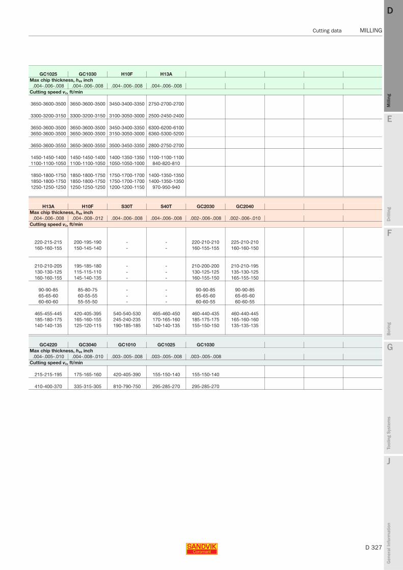
E
D 327
Mill
ing
Drilli
ng
F
Bor
ing
G
Tool
ing
Syst
ems
J
Gen
eral
Info
rmat
ion
DD
Mill
ing
Cutting data MILLING
MILLING Cutting data
GC1025 GC1030 H10F H13AMax chip thickness, hex inch
.004-.006-.008 .004-.006-.008 .004-.006-.008 .004-.006-.008Cutting speed vc, ft/min
3650-3600-3500 3650-3600-3500 3450-3400-3350 2750-2700-2700
3300-3200-3150 3300-3200-3150 3100-3050-3000 2500-2450-2400
3650-3600-3500 3650-3600-3500 3450-3400-3350 6300-6200-61003650-3600-3500 3650-3600-3500 3150-3050-3000 6360-5300-5200
3650-3600-3550 3650-3600-3550 3500-3450-3350 2800-2750-2700
1450-1450-1400 1450-1450-1400 1400-1350-1350 1100-1100-11001100-1100-1050 1100-1100-1050 1050-1050-1000 840-820-810
1850-1800-1750 1850-1800-1750 1750-1700-1700 1400-1350-13501850-1800-1750 1850-1800-1750 1750-1700-1700 1400-1350-13501250-1250-1250 1250-1250-1250 1200-1200-1150 970-950-940
H13A H10F S30T S40T GC2030 GC2040Max chip thickness, hex inch
.004-.006-.008 .004-.008-.012 .004-.006-.008 .004-.006-.008 .002-.006-.008 .002-.006-.010Cutting speed vc, ft/min
220-215-215 200-195-190 - - 220-210-210 225-210-210160-160-155 150-145-140 - - 160-155-155 160-160-150
210-210-205 195-185-180 - - 210-200-200 210-210-195130-130-125 115-115-110 - - 130-125-125 135-130-125160-160-155 145-140-135 - - 160-155-150 165-155-150
90-90-85 85-80-75 - - 90-90-85 90-90-8565-65-60 60-55-55 - - 65-65-60 65-65-6060-60-60 55-55-50 - - 60-60-55 60-60-55
465-455-445 420-405-395 540-540-530 465-460-450 460-440-435 460-440-445185-180-175 165-160-155 245-240-235 170-165-160 185-175-175 165-160-160140-140-135 125-120-115 190-185-185 140-140-135 155-150-150 135-135-135
GC4220 GC3040 GC1010 GC1025 GC1030Max chip thickness, hex inch
.004-.005-.010 .004-.008-.010 .003-.005-.008 .003-.005-.008 .003-.005-.008Cutting speed vc, ft/min
215-215-195 175-165-160 420-405-390 155-150-140 155-150-140
410-400-370 335-315-305 810-790-750 295-285-270 295-285-270
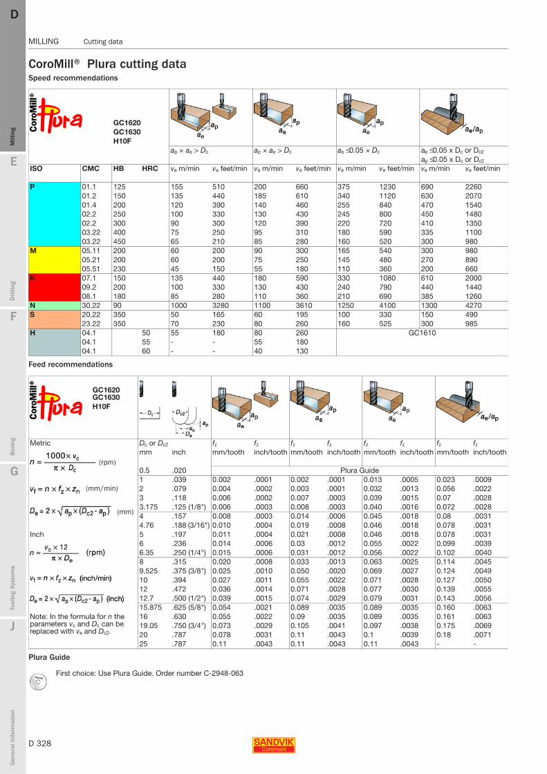
D 328
MILLING Cutting data
E
Mill
ing
Drilli
ng
F
Bor
ing
G
Tool
ing
Syst
ems
J
Gen
eral
Info
rmat
ion
DDM
illin
g
MILLING Cutting data
CoroMill® Plura cutting dataSpeed recommendations
Feed recommendations
Plura Guide
GC1620GC1630H10F
ap × ae > Dc ap × ae > Dc ae ≤ 0.05 × Dc ae ≤ 0.05 x Dc or Dc2
ap ≤ 0.05 x Dc or Dc2
ISO CMC HB HRC ve m/min ve feet/min ve m/min ve feet/min ve m/min ve feet/min ve m/min ve feet/min
P 01.1 125 155 510 200 660 375 1230 690 226001.2 150 135 440 185 610 340 1120 630 207001.4 200 120 390 140 460 255 840 470 154002.2 250 100 330 130 430 245 800 450 148002.2 300 90 300 120 390 220 720 410 135003.22 400 75 250 95 310 180 590 335 110003.22 450 65 210 85 280 160 520 300 980
M 05.11 200 60 200 90 300 165 540 300 98005.21 200 60 200 75 250 145 480 270 89005.51 230 45 150 55 180 110 360 200 660
K 07.1 150 135 440 180 590 330 1080 610 200009.2 200 100 330 130 430 240 790 440 144008.1 180 85 280 110 360 210 690 385 1260
N 30.22 90 1000 3280 1100 3610 1250 4100 1300 4270S 20.22 350 50 165 60 195 100 330 150 490
23.22 350 70 230 80 260 160 525 300 985H 04.1 50 55 180 80 260 GC1610
04.1 55 - - 55 18004.1 60 - - 40 130
GC1620GC1630H10F
Metric Dc or Dc2 fz fz fz fz fz fz fz fz
mm inch mm/tooth inch/tooth mm/tooth inch/tooth mm/tooth inch/tooth mm/tooth inch/tooth
0.5 .020 Plura Guide1 .039 0.002 .0001 0.002 .0001 0.013 .0005 0.023 .00092 .079 0.004 .0002 0.003 .0001 0.032 .0013 0.056 .00223 .118 0.006 .0002 0.007 .0003 0.039 .0015 0.07 .00283.175 .125 (1/8") 0.006 .0003 0.008 .0003 0.040 .0016 0.072 .00284 .157 0.008 .0003 0.014 .0006 0.045 .0018 0.08 .00314.76 .188 (3/16") 0.010 .0004 0.019 .0008 0.046 .0018 0.078 .0031
Inch 5 .197 0.011 .0004 0.021 .0008 0.046 .0018 0.078 .00316 .236 0.014 .0006 0.03 .0012 0.055 .0022 0.099 .00396.35 .250 (1/4") 0.015 .0006 0.031 .0012 0.056 .0022 0.102 .00408 .315 0.020 .0008 0.033 .0013 0.063 .0025 0.114 .00459.525 .375 (3/8") 0.025 .0010 0.050 .0020 0.069 .0027 0.124 .004910 .394 0.027 .0011 0.055 .0022 0.071 .0028 0.127 .005012 .472 0.036 .0014 0.071 .0028 0.077 .0030 0.139 .005512.7 .500 (1/2") 0.039 .0015 0.074 .0029 0.079 .0031 0.143 .005615.875 .625 (5/8") 0.054 .0021 0.089 .0035 0.089 .0035 0.160 .0063
Note: In the formula for n the parameters vc and Dc can be replaced with ve and Dc2.
16 .630 0.055 .0022 0.09 .0035 0.089 .0035 0.161 .006319.05 .750 (3/4") 0.073 .0029 0.105 .0041 0.097 .0038 0.175 .006920 .787 0.078 .0031 0.11 .0043 0.1 .0039 0.18 .007125 .787 0.11 .0043 0.11 .0043 0.11 .0043 - -
First choice: Use Plura Guide. Order number C-2948-063
(rpm)
(mm/min)
(mm)
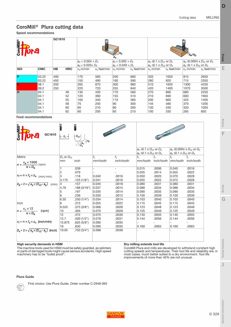
E
D 329
Mill
ing
Drilli
ng
F
Bor
ing
G
Tool
ing
Syst
ems
J
Gen
eral
Info
rmat
ion
DD
Mill
ing
Cutting data MILLING
MILLING Cutting data
CoroMill® Plura cutting dataSpeed recommendations
Feed recommendations
Plura Guide
GC1610
ae < 0.004 × Dc ae < 0.002 × Dc ae ≤ 0.1 x Dc2 or De ae ≤ 0.0004 x Dc2 or De
ap < 0.020× Dc ap < 0.040 × Dc ap ≤ 0.1 x Dc2 or De ap ≤ 0.1 x Dc2 or De
ISO CMC HB HRC ve m/min ve feet/min ve m/min ve feet/min ve m/min ve feet/min ve m/min ve feet/min
P 03.22 400 170 560 200 660 320 1050 815 265003.22 450 150 490 180 590 280 920 715 2350
K 08.1 200 265 870 300 980 510 1650 1300 425009.2 250 220 720 255 840 420 1400 1070 3500
H 04.1 48 130 430 170 560 270 890 680 225004.1 52 120 390 155 510 210 690 600 195004.1 55 105 340 110 360 200 660 425 140004.1 58 75 250 90 300 145 480 370 120004.1 60 65 210 80 260 130 430 320 105004.1 62 60 200 65 210 100 330 265 850
GC1610
ae ≤ 0.1 x Dc2 or De ae ≤ 0.0004 x Dc2 or De
ap ≤ 0.1 x Dc2 or De ap ≤ 0.1 x Dc2 or De
Metric Dc or Dc2 fz fz fz fz fz fz
mm inch mm/tooth inch/tooth mm/tooth inch/tooth mm/tooth inch/tooth
1 .039 - - 0.015 .0006 0.040 .00162 .079 - - 0.035 .0014 0.055 .00223 .118 0.040 .0016 0.050 .0020 0.070 .00283.175 .125 (1/8") 0.041 .0016 0.055 .0022 0.072 .00284 .157 0.045 .0018 0.080 .0031 0.080 .00314.76 .188 (3/16") 0.037 .0015 0.088 .0034 0.088 .00345 .197 0.035 .0014 0.090 .0035 0.090 .00356 .236 0.030 .0012 0.100 .0039 0.100 .00396.35 .250 (1/4") 0.034 .0014 0.103 .0040 0.103 .0040
Inch 8 .315 0.055 .0022 0.115 .0045 0.115 .00459.525 .375 (3/8") 0.066 .0026 0.123 .0048 0.123 .004810 .394 0.070 .0028 0.125 .0049 0.125 .004912 .472 0.075 .0030 0.140 .0055 0.140 .005512.7 .500 (1/2") 0.078 .0031 0.144 .0056 0.144 .005615.875 .625 (5/8") 0.090 .0035 - - - -16 .630 0.090 .0035 0.160 .0063 0.160 .006319.05 .750 (3/4") 0.098 .0038 - - - -
High security demands in HSM Dry milling extends tool lifeThe machine tools used for HSM must be safely guarded, as splinters or parts of damaged tools might cause serious accidents. High speed machinery has to be “bullet proof”.
CoroMill Plura end mills are developed to withstand constant high cutting speeds and temperatures. Their tool life and reliability are, in most cases, much better suited to a dry environment. Tool life improvements of more than 40% are not unusual.
First choice: Use Plura Guide. Order number C-2948-063
(rpm)
(mm/min)
(mm)
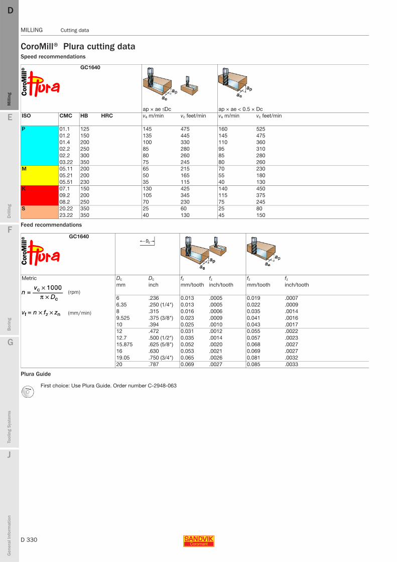
D 330
MILLING Cutting data
E
Mill
ing
Drilli
ng
F
Bor
ing
G
Tool
ing
Syst
ems
J
Gen
eral
Info
rmat
ion
DDM
illin
g
MILLING Cutting data
CoroMill® Plura cutting dataSpeed recommendations
Feed recommendations
Plura Guide
GC1640
ap × ae ≤ Dc ap × ae < 0.5 × DcISO CMC HB HRC ve m/min vc feet/min ve m/min vc feet/min
P 01.1 125 145 475 160 52501.2 150 135 445 145 47501.4 200 100 330 110 36002.2 250 85 280 95 31002.2 300 80 260 85 28003.22 350 75 245 80 260
M 05.11 200 65 215 70 23005.21 200 50 165 55 18005.51 230 35 115 40 130
K 07.1 150 130 425 140 45009.2 200 105 345 115 37508.2 250 70 230 75 245
S 20.22 350 25 60 25 8023.22 350 40 130 45 150
GC1640
Metric Dc Dc fz fz fz fz
mm inch mm/tooth inch/tooth mm/tooth inch/tooth
6 .236 0.013 .0005 0.019 .00076.35 .250 (1/4") 0.013 .0005 0.022 .00098 .315 0.016 .0006 0.035 .00149.525 .375 (3/8") 0.023 .0009 0.041 .001610 .394 0.025 .0010 0.043 .001712 .472 0.031 .0012 0.055 .002212.7 .500 (1/2") 0.035 .0014 0.057 .002315.875 .625 (5/8") 0.052 .0020 0.068 .002716 .630 0.053 .0021 0.069 .002719.05 .750 (3/4") 0.065 .0026 0.081 .003220 .787 0.069 .0027 0.085 .0033
First choice: Use Plura Guide. Order number C-2948-063
(rpm)
(mm/min)
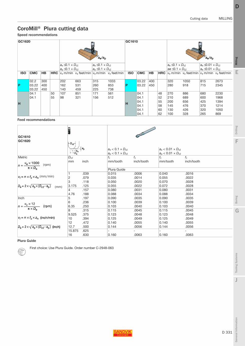
E
D 331
Mill
ing
Drilli
ng
F
Bor
ing
G
Tool
ing
Syst
ems
J
Gen
eral
Info
rmat
ion
DD
Mill
ing
Cutting data MILLING
MILLING Cutting data
CoroMill® Plura cutting dataSpeed recommendations
Feed recommendations
Plura Guide
GC1620 GC1610
ae ≤ 0.1 × Dc2 ae ≤ 0.1 × Dc2 ae ≤ 0.1 × Dc2 ae ≤ 0.01 × Dc2
ap ≤ 0.1 × Dc2 ap ≤ 0.1 × Dc2 ae ≤ 0.1 × Dc2 ae ≤ 0.01 × Dc2
ISO CMC HB HRC ve m/min ve feet/min ve m/min ve feet/min ISO CMC HB HRC ve m/min ve feet/min ve m/min ve feet/min
P02.2 300 202 663 315 1033
P03.22 400 320 1050 815 2673
03.22 400 162 531 260 853 03.22 450 280 918 715 234503.22 450 140 459 225 738
H
04.1 50 107 851 171 561
H
04.1 48 270 886 680 223004.1 55 98 321 156 512 04.1 52 210 689 600 1968
04.1 55 200 656 425 139404.1 58 145 476 370 121404.1 60 130 426 320 105004.1 62 100 328 265 869
GC1610GC1620
ae < 0.1 × Dc2 ae < 0.01 × Dc2
ap < 0.1 × Dc2 ap < 0.01 × Dc2
Metric Dc2 fz fz fz fz
mm inch mm/tooth inch/tooth mm/tooth inch/tooth
Plura Guide1 .039 0.015 .0006 0.040 .00162 .079 0.035 .0014 0.055 .00223 .118 0.050 .0020 0.070 .00283.175 .125 0.055 .0022 0.072 .00284 .157 0.080 .0031 0.080 .00314.76 .188 0.088 .0034 0.088 .0034
Inch 5 .197 0.090 .0035 0.090 .00356 .236 0.100 .0039 0.100 .00396.35 .250 0.103 .0040 0.103 .00408 .315 0.115 .0045 0.115 .00459.525 .375 0.123 .0048 0.123 .004810 .394 0.125 .0049 0.125 .004912 .472 0.140 .0055 0.140 .005512.7 .500 0.144 .0056 0.144 .005615.875 .625 - - - -16 .630 0.160 .0063 0.160 .0063
First choice: Use Plura Guide. Order number C-2948-063
(rpm)
(mm/min)
(mm)
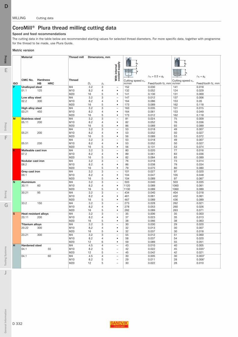
D 332
MILLING Cutting data
E
Mill
ing
Drilli
ng
F
Bor
ing
G
Tool
ing
Syst
ems
J
Gen
eral
Info
rmat
ion
DDM
illin
g
MILLING Cutting data
CoroMill® Plura thread milling cutting dataSpeed and feed recommendationsThe cutting data in the table below are recommended starting values for selected thread diameters. For more specific data, together with programme for the thread to be made, use Plura Guide.
Metric version
Material Thread mill Dimensions, mm
Wit
h in
tern
al
coo
lant
sup
ply
Hardness /Th = 0.5 × ap /Th = ap
CMC No. Thread Cutting speed vc, m/min Feed/tooth fz, mm
Cutting speed vc, m/min Feed/tooth fz, mmISO HB HRC Dc zn
P Unalloyed steel M4 3.2 3 – 152 0.030 141 0.01801.1 125 M10 8.2 4 • 132 0.052 124 0.029
M20 16 5 • 141 0.130 131 0.069Low alloy steel M4 3.2 3 – 147 0.012 137 0.00602.2 300 M10 8.2 4 • 164 0.086 153 0.05
M20 16 5 • 173 0.089 162 0.118High alloy steel M4 3.2 3 – 163 0.035 151 0.01503.21 450 M10 8.2 4 • 164 0.061 153 0.049
M20 16 5 • 173 0.012 162 0.118M Stainless steel M4 3.2 3 – 81 0.024 75 0.009
05.11 200 M10 8.2 4 • 82 0.052 76 0.036M20 16 5 • 86 0.089 93 0.089M4 3.2 3 – 53 0.018 49 0.007
05.21 200 M10 8.2 4 • 53 0.052 50 0.027M20 16 5 • 56 0.089 53 0.072M4 3.2 3 – 53 0.018 49 0.007
05.51 230 M10 8.2 4 • 53 0.052 50 0.027M20 16 5 • 56 0.131 53 0.074
K Malleable cast iron M4 3.2 3 – 80 0.020 77 0.01607.2 M10 8.2 4 • 89 0.061 83 0.036
M20 16 5 • 82 0.084 83 0.089Nodular cast iron M4 3.2 3 – 76 0.018 73 0.01408.2 M10 8.2 4 • 86 0.038 79 0.034
M20 16 5 • 79 0.075 80 0.080Grey cast iron M4 3.2 3 – 101 0.027 97 0.02009.1 M10 8.2 4 • 104 0.047 105 0.048
M20 16 5 • 104 0.089 97 0.067N Aluminium M4 3.2 3 – 503 0.040 503 0.035
30.11 60 M10 8.2 4 • 1120 0.089 1060 0.061M20 16 5 • 1130 0.089 1060 0.089
30.21 95 M4 3.2 3 – 434 0.040 404 0.018M10 8.2 4 • 461 0.061 432 0.061M20 16 5 • 467 0.089 436 0.089
33.2 150 M4 3.2 3 – 273 0.028 262 0.021M10 8.2 4 • 278 0.053 260 0.026M20 16 5 • 282 0.089 263 0.071
S Heat resistant alloys M4 3.2 3 – 35 0.006 35 0.00320.11 200 M10 8.2 4 • 37 0.023 35 0.013
M20 16 5 • 38 0.066 38 0.063Titanium alloys M4 3.2 3 – 30 0.030 29 0.02020.22 300 M10 8,2 4 • 32 0.013 30 0.007
M20 16 5 • 32 0.037 30 0.01823.21 300 M4 3.2 3 – 55 0.012 51 0.060
M10 8.2 4 • 58 0.037 54 0.020M20 12 6 • 59 0.089 55 0.051
H Hardened steel M4 4.5 4 – 43 0.010 40 0.00504.1 55 M10 8.2 5 – 42 0.022 45 0.035*
M20 12 5 – 45 0.042 42 0.02104.1 60 M4 4.5 4 – 30 0.005 30 0.003*
M10 8.2 5 – 29 0.011 28 0.006*M20 12 5 – 30 0.022 28 0.010
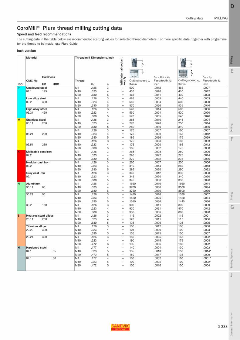
E
D 333
Mill
ing
Drilli
ng
F
Bor
ing
G
Tool
ing
Syst
ems
J
Gen
eral
Info
rmat
ion
DD
Mill
ing
Cutting data MILLING
MILLING Cutting data
CoroMill® Plura thread milling cutting dataSpeed and feed recommendationsThe cutting data in the table below are recommended starting values for selected thread diameters. For more specific data, together with programme for the thread to be made, use Plura Guide.
Inch version
Material Thread mill Dimensions, inch
Wit
h in
tern
al c
oo
lant
su
pp
lyHardness /Th = 0.5 × ap /Th = ap
CMC No. Thread Cutting speed vc Feed/tooth, fz Cutting speed vc, Feed/tooth, fzISO HB HRC Dc zn ft/min inch ft/min inchP Unalloyed steel M4 .126 3 – 500 .0012 465 .0007
01.1 125 M10 .323 4 • 435 .0020 410 .0012M20 .630 5 • 465 .0051 430 .0028
Low alloy steel M4 .126 3 – 485 .0005 440 .000302.2 300 M10 .323 4 • 540 .0034 500 .0020
M20 .630 5 • 570 .0036 535 .0046High alloy steel M4 .126 3 – 540 .0014 500 .000603.21 450 M10 .323 4 • 550 .0024 520 .0020
M20 .630 5 • 570 .0005 540 .0046M Stainless steel M4 .126 3 – 265 .0010 245 .0004
05.11 200 M10 .323 4 • 270 .0020 250 .0014M20 .630 5 • 280 .0036 310 .0036M4 .126 3 – 175 .0007 160 .0007
05.21 200 M10 .323 4 • 175 .0020 165 .0012M20 .630 5 • 185 .0036 175 .0029M4 .126 3 – 175 .0008 160 .0003
05.51 230 M10 .323 4 • 175 .0020 165 .0012M20 .630 5 • 185 .0052 175 .0030
K Malleable cast iron M4 .126 3 – 265 .0008 260 .000607.2 M10 .323 4 • 290 .0022 275 .0014
M20 .630 5 • 270 .0032 275 .0036Nodular cast iron M4 .126 3 – 260 .0007 250 .000608.2 M10 .323 4 • 310 .0014 285 .0013
M20 .630 5 • 285 .0030 290 .0032Grey cast iron M4 .126 3 – 340 .0012 330 .000809.1 M10 .323 4 • 345 .0020 340 .0020
M20 .630 5 • 345 .0036 330 .0026N Aluminium M4 .126 3 – 1660 .0016 1660 .0014
30.11 60 M10 .323 4 • 3700 .0036 3500 .0024M20 .630 5 • 3750 .0036 3500 .0036
30.21 95 M4 .126 3 – 1430 .0016 1330 .0007M10 .323 4 • 1520 .0025 1420 .0034M20 .630 5 • 1540 .0036 1445 .0036
33.2 150 M4 .126 3 – 900 .0011 890 .0009M10 .323 4 • 920 .0021 870 .0012M20 .630 5 • 930 .0036 880 .0028
S Heat resistant alloys M4 .126 3 – 115 .0002 115 .000120.11 200 M10 .323 4 • 120 .0011 115 .0006
M20 .630 5 • 125 .0026 125 .0025Titanium alloys M4 .126 3 – 100 .0012 100 .000820.22 300 M10 .323 4 • 105 .0006 100 .0003
M20 .630 5 • 105 .0015 100 .000723.21 300 M4 .126 3 – 180 .0005 165 .0022
M10 .323 4 • 190 .0015 175 .0008M20 .472 6 • 195 .0036 180 .0022
H Hardened steel M4 .177 4 – 140 .0004 130 .000204.1 55 M10 .323 5 – 135 .0010 150 .0014*
M20 .472 5 – 150 .0017 135 .000904.1 60 M4 .177 4 – 100 .0002 100 .0001*
M10 .323 5 – 100 .0005 100 .0002*M20 .472 5 – 100 .0010 100 .0004

D 334
MILLING Grade descriptions
E
Mill
ing
Drilli
ng
F
Bor
ing
G
Tool
ing
Syst
ems
J
Gen
eral
Info
rmat
ion
DDM
illin
g
MILLING Grade descriptions
Grades for milling
The position and form of the grade symbols indicate the suitable field of application.
Centre of the field of application.
Recommended field of application.
Stable
Unstable
Ste
elS
tain
less
ste
el
Cas
t ir
on
No
n-fe
rro
us m
etal
sH
eat
resi
stan
t an
d s
uper
allo
ysH
ard
ened
m
ater
ials
= Basic grades
= Complementary grades
Low Heat High Low Heat High
Low Heat High Low Heat High

E
D 335
Mill
ing
Drilli
ng
F
Bor
ing
G
Tool
ing
Syst
ems
J
Gen
eral
Info
rmat
ion
DD
Mill
ing
Grade descriptions MILLING
MILLING Grade descriptions
Grades for milling
Basic gradesGC4230 (HC) - P30 (P10-P40)Allround grade for modern machining with a good balance of security and productivity. Coated carbide grade for light to heavy milling (both wet and dry) in unalloyed and low alloyed steels. First choice in face milling and an optimizer for higher productivity in shoulder milling.GC4220 (HC) - P20 (P10-P25)Coated carbide grade optimized for best productivity in steel milling. Grade for dry machining with high chip removal rate.GC4240 (HC) – P40 (P35 – P50)Coated carbide grade for toughness demanding operation in steel milling. For end mill and square shoulder concepts grade GC4240 should be used in more stable conditions like short overhang , face milling, shallow shoulder milling etc. For other concepts grade GC4240 is the first or backup choice in toughness operation. Benefits of security. Suitable for small batch production of mixed material. Workes well both with or without coolant. GC1030 (HC) – P30 (P15 – P35)PVD-coated carbide grade. GC1030 is the first choice in unstablie conditions like Longedge, chip jamming, deep shoulder and endmilling. long overhang, Turnmill operations etc. Can be used as a backup choise in toughness operation. In combiation with perifery ground inserts first choice for sticky materials e g low-carbone steel.CT530 (HT) – P15 (P10 – P15)Cermet grade for light milling operations mainly without coolant. The high resistance to plastic deformation and smearing/buildt-up edges makes it suitalble for a wide cutting speed range. Ideal grade for Wiper inserts.
Complementary gradesGC1010 (HC) – P10 (P05-P15)PVD-coated carbide grade for milling within application area of typical pre-harden and plastic mould steel from 36HRC and above.GC2030 (HC) – P35 (P25 – P40)PVD-coated carbide grade for milling of low-carbon steels that tends to build up edges. Also very suitable for 90 degree milling in mixed materials.GC2040 (HC) – P45 (P30 – P50)Coated carbide grade for milling of steels when a combination of sharp cutting edges and a tough grade is needed at low speeds. Very useful for small batch production of mixed materials.GC3040 (HC) – P20 (P10 – P40)Coated carbide grade with very good abrasive wear resistance for rough milling of steel at medium to high speeds.SM30 (HW) – P35 (P30 – P40)Uncoated carbide grade for medium to rough milling at low to moderate cutting speed. Good edge security in hard materials and at unstable conditions.GC1025 (HC) – P30 (P15 – P30)PVD-coated carbide grade for light milling of steel. In combination with perifery ground inserts first choice for sticky materials e.g. low-carbon steels.
Steel
Basic gradesGC1030 (HC) – M15 (M10 – M25)PVD-coated carbide grade for light milling of stainless steel. In combination with perifery ground inserts 1:st choice for sticky and workhardening materials.GC2030 (HC) – M25 (M15 – M30)PVD-coated carbide grade for milling of stainless steels (mainly austenitic types) at medium to high speeds. In combination with positive geometries also suitable for heat resistant material and titanium.GC2040 (HC) – M40 (M25 – M40)Coated carbide grade for milling of stainless steels with abrasive tendencies e. g. cast components, ferritic/ martensitic stainless steels and PH-steels at medium speeds. Also useful for small batch production of mixed materials.
GC1040 (HC) - M35 (M25-M40)A tough PVD-coated carbide grade, for milling under difficult conditions with low to intermediate cutting speed and/or feed, For application where demands on edgeline security and edge sharpness is high. Primarily for sticky austenitic and duplex stainless steels, 1:st choise is dry but also wet.
Complementary gradesGC4240 (HC) – M40 (M30 – M40)Coated carbide grade for medium to heavy operations of stainless steel castings. Very suitable for small batch production of mixed materials.CT530 (HT) – M10 (M10 – M15)Cermet grade for light milling of austenitic/ duplex stainless steels. The high resistance to plastic deformation/ smearing/ built-up edges makes it suitable for a wide cutting speed range in dry conditions.SM30( HW) – M30 (M20 – M30) Uncoated carbide grade for medium to rough milling at low to moderate cutting speed. Good edge security at unstable conditions.GC4230 (HC) – M30 (M25 – M35)Coated carbide grade for light to heavy milling in martensitic stainless steels.GC1025 (HC) – M15 (M10 – M20)PVD-coated carbide grade for light milling of stainless steel. In combination with perifery ground inserts first choice for sticky and workhardening materials.GC1010 (HC) – M10 (M05 – M10)PVD-coated grade for very stable conditions.S30T (HC) – M25 (M15 – M35)A PVD-coated cemented carbide, for milling under stable conditions with medium to high cutting speeds, For applications where demands on edgeline security and reliability is high, such as sticky austenitic and duplex stainless steels, 1:st choise is dry but also wet.S40T (HC) – M45 (M30 – M45)A tough MT-CVD-coated cemented carbide, for milling in very toughness demanding operations of stainless steels, also useful in operations with abrasive tendencies e g cast components, ferritic/ martensitic stainless steels and PH-steels at medium speeds. Also useful for small batch production of mixed materials.
Austenitic/ferritic/martensitic stainless steel

D 336
MILLING Grade descriptions
E
Mill
ing
Drilli
ng
F
Bor
ing
G
Tool
ing
Syst
ems
J
Gen
eral
Info
rmat
ion
DDM
illin
g
MILLING Grade descriptions
Grades for milling
Basic gradesGC3040 (HC) - K30 (K20 – K40)Coated carbide grade for toughness demanding milling of cast iron e.g. nodular cast iron, wet conditions or high tensile iron. Long predictable tool life at low to medium cutting speeds.GC3220 (HC) – K15 (K10 – K25)CVD-coated carbide grade for medium to rough milling of grey cast iron mainly under dry conditions.Long predictable tool life at medium to high cutting speeds.GC1020 (HC) – K20 (K10 – K25)PVD-coated carbide grade for medium to rough milling of grey and nodular cast iron under wet conditions. To be used at medium to high speeds with predictable tool life.CB50 (BN) – K10 (K01 – K20)CB50 is a cubic boron nitride tipped grade. It gives a high edge toughness combined with good wear resistance. CB50 is well suited for machining of cast iron under favourable conditions.K20W (HC) - K20 (K15 - K30)Coated carbide grade for medium to rough milling of grey cast iron under wet conditions. To be used at low to medium speeds.CC6190 (CN) – K05 (K01 – K15)Silicon nitride ceramic grade for light roughing to semifinishing of grey cast iron at high cutting speeds.
Complementary gradesK20D (HC) - K15 (K10-K20)MTCVD coated grade for medium to rough milling of cast iron. Mainly without coolant. Long tool life with high speed capability.H13A (HW) – K20 (K10 – K25)Uncoated carbide grade with wear resistance and toughness for light to medium milling at moderate cutting speeds. Ideal choice for milling of ferritic nodular cast iron.GC1010 (HC) – K05 (K01-K10)PVD-coated carbide grade for finishing milling in grey and nodular cast iron. A long tool life can be received with a sustained surface finish.GC4220 (HC) – K25 (K20 – K30)Coated carbide grade for light to heavy milling of cast iron at medium speeds. To complement GC3000 grades in operations.GC4230 (HC) – K30 (K20 – K35)Coated carbide grade for light to heavy milling of nodular cast iron.GC4240 (HC) – K40 (K30 – K40)Coated carbide grade for medium to heavy operations at low speeds where the toughness demand is high.K15W(HC) – K15 (K10 – K25)Coated carbide grade for milling of grey cast iron under wet conditions.To be used at medium speeds.
Cast iron
Basic gradesCD10 (DP) – N05 (N01 – N10)Polycrystalline diamond tipped grade for machining of non ferrous and non metallic materials. Gives long tool life, clean cut and good surface finish.H10 (HW) – N10 (N05 – N15)Uncoated finegrained carbide grade,that gives excellent edge sharpness, for milling of aluminium.H13A (HW) – N15 (N10 – N25)Uncoated carbide grade suitable for milling of aluminium alloys in combination with "sharp" cutting edges.
Complementary gradesCT530 (HT) – N15 (N10 – N20)Cermet grade mainly recommended at high RPM when milling aluminium thanks to the low tendency to build up edges and low weight of the inserts.GC1025 (HC) – N15 (N10 – N25)PVD-coated carbide grade for rough milling of aluminium alloys in combination with ground cutting edges.H10F (HW) – N15 (N10 – N25)Uncoated carbide grade suitable for milling of aluminium alloys in combination with "sharp" cutting edges.GC1030 (HC) - N15 (N10-N25)PVD-coated carbide grade for rough milling of aluminium alloys in combination with ground cutting edges.
Non ferrous metals, plastics, wood

E
D 337
Mill
ing
Drilli
ng
F
Bor
ing
G
Tool
ing
Syst
ems
J
Gen
eral
Info
rmat
ion
DD
Mill
ing
Grade descriptions MILLING
MILLING Grade descriptions
Grades for milling
Basic gradesH10F (HW) – S25 (S20 – S30)Uncoated carbide grade with fine grain sizes. High notch wear resistance makes it suitable for milling of aerospace materials e.g. titanium.GC2030 (HC) – S20 (S15 – S25)PVD-coated carbide grade for semifinishing to light roughing of heat resistant superalloys at low speeds.GC1030 (HC) – S15 (S10 – S20)PVD-coated carbide grade for milling of heat resistant super alloys at medium speeds. Good resistance to built-up edges and plastic deformation.GC2040 (HC) – S30 (S25 – S40)Coated carbide grade for milling of cast heat resistant alloys.S30T (HC) – S25 (S15 – S30)First choice grade for titanium milling. PVD-coated grade that combines high edge strength and bulk toughness. It has good resistance to micro-chipping and keeps the cutting edge line intact longer. The grade focuses on high performance at elevated cutting speeds.S40T (HC) – S35 (S25 – S45)CVD-coated grade for milling of titanium. First choice grade during moderate to severe vibrations and in toughness demanding operations. It has high bulk toughness and high edge strength. Wear grows slowly, making cutting edge duller without breaking.GC1010 (HC) – S10 (S05 – S10)PVD-coated carbide grade for milling of titanium during very good conditions. An optimizer with excellent wear resistance at elevated cutting speeds. Sensitive to instability and vibrations.
Complementary gradesH13A (HW) – S20 (S15 – S25)Uncoated carbide grade with good abrasive wear resistance and toughness for milling of heat resistant alloys under moderate cutting speeds and feeds.GC1025 (HC) – S20 (S10 – S20)PVD-coated carbide grade for milling of heat resistant superalloys at medium speeds. Good resistance to buildt up edges and plastic deformation.GC1040 (HC) – S30 (S20 – S35) A tough PVD-coated carbide grade, for milling under difficult conditions with low to intermediate cutting speed and/or feed, For application where demands on edgeline security and edge sharpness is high. Primarily for sticky austenitic and duplex stainless steels.
Heat resistant alloys Titanium alloys
Basic gradesCB50 (BN) – H05 (H01 – H10)CB50 is a cubic boron nitride tipped grade. It gives a high edge toughness combined with good wear resistance. CB50 is well suited for machining of hardened steel under favourable conditions.CC6190 (HC) – H10 (H05 – H15)Silicon nitride ceramic grade suitable for semi-finish milling of chilled cast iron at medium to high speed.GC1010 (HC) – H10 (H05-H15)PVD-coated carbide grade for machining in hardened steel. Can handle large portion of machining demands from roughing to finishing operations. Due to exeptional plastic deformation resistance, thermal crack resistance and good wear resitans the grade can withstand long time in cut. Suitable for machining of hardened steel from 36HRC and above.GC1030 (HC) - H10 (H10-H20)PVD-coated carbide grade for milling of hardened components at low feeds and moderate speeds.GC4220 (HC) – H25 (H15 – H30)Coated carbide grade for light roughing under favourable conditions of hardened steel up to HRC 60. Can take high temperatures.
Complementary gradesCT530 (HT) – H25 (H10 – H25)Cermet grade for finish milling of hardened steel components at low to medium speeds.GC3040 (HC) – H25 (H20 – H30)Coated carbide grade for rough milling of hardened steel at fair conditions and low to medium speeds.GC1025 (HC) – H15 (H10 – H20)PVD-coated carbide grade for milling of hardened components at low feeds and moderate speeds.H1P (HW) – H10 (H05 – H15)Uncoated carbide grade for finishing chilled cast iron at medium speeds.
Hardened steel
Letter symbols specifying the designation of hard cutting materials:
Hardmetals: HW Uncoated hardmetal containing primarily
tungsten carbide (WC)
HT Uncoated hardmetal, also called cermet, containing primarily titanium carbides (TIC) or titanium nitrides (TIN) or both.
HC Hardmetals as above, but coated
Ceramics:CA Oxide ceramics containing primarily
aluminium oxide (Al2O3).
CM Mixed ceramics containing primarily aluminium oxide (Al2O3) but containing components other than oxides.
CN Nitride ceramics containing primarily silicon nitride (Si3N4).
CC Ceramics as above, but coated.
Diamond:DP Polycrystalline diamond1)
Boron nitride:BN Polycrystalline boron nitride1)
1) Polycrystalline diamond and polycrystalline boron nitride are also named superhard cutting materials.