Embed Size (px)
Citation preview
13
Siemens ET B1 · 10/2009
13
13/2 Product overview
13/4 5SV8 residual current monitors
13/11 5TT3 voltage relays
13/19 5TT6 current relays
13/25 5TT6 priority switches
13/26 5TT3 fuse monitors
13/28 5TT3 phase and phase sequence monitors
13/30 5TT3 insulation monitors
13/33 7LQ3 insulation monitors for medical premises
BETA MonitoringMonitoring of Electrical Values
ET_B1_2009-06_UEB_en.book Page 1 Montag, Dezember 7, 2009 1:05 PM
© Siemens AG 2009
BETA MonitoringMonitoring of Electrical Values
Product overview
13/2 Siemens ET B1 · 10/2009
13
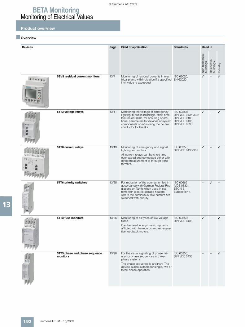
■ Overview
Devices Page Field of application Standards Used in
Non
-res
iden
tial
bui
ldin
gs
Res
iden
tial
bui
ldin
gs
Ind
ustr
y
5SV8 residual current monitors 13/4 Monitoring of residual currents in elec-trical plants with indication if a specified limit value is exceeded.
IEC 62020, EN 62020
✓ -- ✓
5TT3 voltage relays 13/11 Monitoring the voltage of emergency lighting in public buildings, short-time failures of 20 ms, for ensuring opera-tional parameters for devices or system components or monitoring the neutral conductor for breaks.
IEC 60255; DIN VDE 0435-303; DIN VDE 0108; DIN VDE 0435; DIN VDE 0633
✓ -- ✓
5TT6 current relays 13/19 Monitoring of emergency and signal lighting and motors.
All current relays can be short-time overloaded and connected either with direct measurement or through trans-formers.
IEC 60255; DIN VDE 0435-303
✓ -- ✓
5TT6 priority switches 13/25 For reduction of the connection fee in accordance with German Federal Reg-ulations on Tariffs when used in sys-tems with electric storage heaters where the continuous-flow heaters are switched with priority.
IEC 60669 (VDE 0632); BTO § 6 Subsection 4
-- ✓ --
5TT3 fuse monitors 13/26 Monitoring of all types of low-voltage fuses.
Can be used in asymmetric systems afflicted with harmonics and regenera-tive feedback motors.
IEC 60255; DIN VDE 0435
✓ -- ✓
5TT3 phase and phase sequence monitors
13/28 For the visual signaling of phase fail-ures or phase sequences in three-phase systems.
The phase sequence is arbitrary. The device is also suitable for single, two or three-phase operation.
IEC 60255; DIN VDE 0435
-- -- ✓
ET_B1_2009-06_UEB_en.book Page 2 Montag, Dezember 7, 2009 1:05 PM
© Siemens AG 2009

BETA MonitoringMonitoring of Electrical Values
Product overview
13/3Siemens ET B1 · 10/2009
13
5TT3 insulation monitors 13/30 We recommend the use of insulation monitors in all systems withoutgrounding.
Adjustable alarm value 2 to 100 kΩ and electrical isolation of measuring circuit, power supply and contact voltage.
IEC 60255; IEC 61557
-- -- ✓
7LQ3 insulation monitors for medical premises
13/33 For the insulation monitoring of a medical IT system or the load current monitoring of an IT system transformer for a non-permissible temperature rise.
Monitoring of the voltage supply with automatic switchover.
EN 61557-8; IEC 61557-8; DIN VDE 0100-710; IEC 60364-7-710
✓ -- --
Devices Page Field of application Standards Used in
Non
-res
iden
tial
bui
ldin
gs
Res
iden
tial
bui
ldin
gs
Ind
ustr
y
ET_B1_2009-06_UEB_en.book Page 3 Montag, Dezember 7, 2009 1:05 PM
© Siemens AG 2009

BETA MonitoringMonitoring of Electrical Values
5SV8 residual current monitors
13/4 Siemens ET B1 · 10/2009
13
■ Overview
Plant safety and operating safety are becoming increasingly im-portant alongside the protection of personnel. Shutdowns due to the unexpected tripping of protective devices are expensive and to be avoided. It is possible to detect residual currents in the electrical installation before the protective device responds.
Residual current monitors (RCM) monitor residual current in electrical installations and issue a signal when the residual cur-rent exceeds a set value.
This enables plant operators to detect and remedy faults before the plant is shut down unexpectedly.
Unwanted circuit disconnections can be avoided by timely de-tection and correctly initiated actions. A residual current monitor (RCM) is designed to monitor an electrical installation for resid-ual current and to issue a signal when the residual current ex-ceeds a set value.
RCMs are used primarily in plants where a fault should result in a signal but not in disconnection. This enables plant operators to detect faults and eliminate their causes before the protective de-vices disconnect the installation, which increases plant and op-erating safety and cuts costs.
The summation current transformer detects all conductors re-quired to conduct the current, i. e. also the neutral conductor where applicable. In a fault-free system, the magnetizing effects of the conductors through which current is flowing cancel each other out for the summation current transformer, i. e.i. e. the sum of all currents is zero. If a residual current is flowing due to an in-sulation fault, a residual magnetic field is left in the core of the transformer and produces a voltage. This voltage is evaluated using the electronics of the RCM. The switched contact can be used e. g. to operate an acoustic/optical signaling device, a higher-level control system or a circuit breaker.
Time characteristic of the rated residual current IΔn
■ Benefits
• Higher plant availability and operating safety through perma-nent monitoring of residual currents
• Adjustable limit values for residual current and response time enable timely detection and signaling – plant shutdowns are often avoidable
• Devices for every application: The summation current transformers are available in various sizes, the RCMs can be used optionally for signaling and/or switching.
• Additional fire protection can be implemented using the mon-itoring system.
■ Technical specifications
1) INS: Instantaneous, SEL: selective.
100 % I n
I
50 % I
t
n
nR
esid
ual c
urre
nt
Time
Alarm
Disconnection
44061_2IRCM analog, type A
RCM digital, type A
RCM digital, 4 channels, type A
Standards EN 62020, IEC 62020
Rated operational voltage Ue V AC 230• Frequency Hz 50/60
Rated residual current IΔn A 0.03 ... 5 0.03 ... 30 0.03 ... 30
Response time tv s 0.02 ... 5 0.02 ... 10, INS, SEL1) 0.02 ... 10, INS, SEL1)
Relay contacts 1 × alarm 1 × alarm, 1 × tripping operation
1 × alarm, 1 × tripping operation
• Rated voltage V AC 230 230 230• Rated current A 6 6 6
Summation current transformer mm ∅ 20 ... 210
Test/Reset Yes/Yes
External tripping operation/external reset --/Yes Yes/Yes Yes/Yes
Mounting width MW 2 3 3
Degree of protection• Contacts IP20• Front IP41
Operating temperature °C -10 ... +50
ET_B1_2009-06_UEB_en.book Page 4 Montag, Dezember 7, 2009 1:05 PM
© Siemens AG 2009

BETA MonitoringMonitoring of Electrical Values
5SV8 residual current monitors
13/5Siemens ET B1 · 10/2009* You can order this quantity or a multiple thereof.
13
■ Selection and ordering data
1) Mounting on standard mounting rail with optional holder for standard mounting rail also possible.
Rated opera-tional voltage
Rated residual current
Response time Mount-ing width
DT Order No. Priceper PU
PU PS*/P. unit
PG Weightper PU
approx.
Ue IΔn tvV AC A s MW Unit(s) Unit(s) kg
RCM analog, type A
230, 50/60 Hz 0.03 ... 5 0.02 ... 5 2 B 5SV8 000-6KK 1 1 027 0.163
RCM digital, type A
230, 50/60 Hz 0.03 ... 30 0.02 ... 10, INS, SEL
3 B 5SV8 001-6KK 1 1 027 0.236
RCM digital, 4 channels, type A
230, 50/60 Hz 0.03 ... 30 0.02 ... 10, INS, SEL
3 B 5SV8 200-6KK 1 1 027 0.236
Internal diameter DT Order No. Priceper PU
PU PS*/P. unit
PG Weightper PU
approx.
mm Unit(s) Unit(s) kg
Summation current transformers
Including holder for standard mounting rail
20 B 5SV8 700-0KK 1 1 027 0.076
30 B 5SV8 701-0KK 1 1 027 0.095
Including holder for wall mounting1) 35 B 5SV8 702-0KK 1 1 027 0.18170 B 5SV8 703-0KK 1 1 027 0.274105 B 5SV8 704-0KK 1 1 027 0.545
Including holder for wall mounting 140 B 5SV8 705-0KK 1 1 027 1.222210 B 5SV8 706-0KK 1 1 027 2.040
Holders for standard mounting rails B 5SV8 900-1KK 1 2 027 0.004
Suitable for summation current trans-former with internal diameter 20 mm, 30 mm, 35 mm, 70 mm and 105 mm
ET_B1_2009-06_UEB_en.book Page 5 Montag, Dezember 7, 2009 1:05 PM
© Siemens AG 2009
BETA MonitoringMonitoring of Electrical Values
5SV8 residual current monitors
13/6 Siemens ET B1 · 10/2009
13
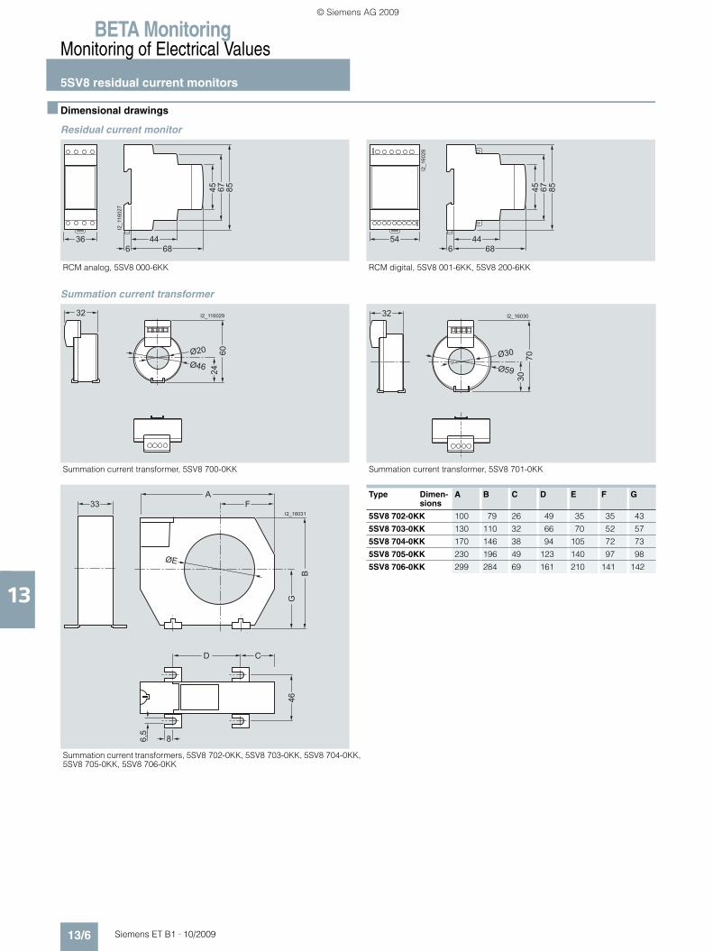
■ Dimensional drawings
Residual current monitor
Summation current transformer
RCM analog, 5SV8 000-6KK RCM digital, 5SV8 001-6KK, 5SV8 200-6KK
I2_1
1602
7
36
45 67 8544
68654 44
686
I2_1
6028
45 67 85
Summation current transformer, 5SV8 700-0KK Summation current transformer, 5SV8 701-0KK
Type Dimen-sions
A B C D E F G
5SV8 702-0KK 100 79 26 49 35 35 43
5SV8 703-0KK 130 110 32 66 70 52 57
5SV8 704-0KK 170 146 38 94 105 72 73
5SV8 705-0KK 230 196 49 123 140 97 98
5SV8 706-0KK 299 284 69 161 210 141 142
Summation current transformers, 5SV8 702-0KK, 5SV8 703-0KK, 5SV8 704-0KK, 5SV8 705-0KK, 5SV8 706-0KK
I2_116029
Ø46
Ø20
2460
32 I2_16030
Ø59
Ø30
3070
32
I2_16031
ØE
G46
6,5
B
F33A
D
8
C
ET_B1_2009-06_UEB_en.book Page 6 Montag, Dezember 7, 2009 1:05 PM
© Siemens AG 2009

BETA MonitoringMonitoring of Electrical Values
5SV8 residual current monitors
13/7Siemens ET B1 · 10/2009
13
■ Schematics
Residual current monitor
RCM analog, 5SV8 000-6KK, shunt trip (ST) RCM analog, 5SV8 000-6KK, shunt trip (ST), self-acknowledging
RCM analog, 5SV8 000-6KK, undervoltage release (UR) RCM analog, 5SV8 000-6KK, undervoltage release (UR), self-acknowledging
ST = shunt tripUR = undervoltage release
1S11S2
2S12S2
I202
_160
32a
L1 L2 L3 N
5 6 7 8
L N S1
NO C NC
S2
1 2 3 4
1S1
1S2
ST
1S11S2
2S12S2
I202
_160
34a
L1 L2 L3 N
1S1
1S2
5 6 7 8
1 2 3 4
L N S1
NO C NC
S2
ST
I202
_160
33a
1S11S2
2S12S2
L1 L2 L3 N
1S1
1S2
5 6 7 8
1 2 3 4
L N S1
NO C NC
S2
UR
1S11S2
2S12S2
I202
_160
35a
L1 L2 L3 N
1S1
1S2
5 6 7 8
1 2 3 4
L N S1
NO C NC
S2
UR
ET_B1_2009-06_UEB_en.book Page 7 Montag, Dezember 7, 2009 1:05 PM
© Siemens AG 2009

BETA MonitoringMonitoring of Electrical Values
5SV8 residual current monitors
13/8 Siemens ET B1 · 10/2009
13
RCM digital, 5SV8 001-6KK, shunt trip (ST) RCM digital, 5SV8 001-6KK, shunt trip (ST), self-acknowledging
RCM digital, 5SV8 001-6KK, undervoltage release (UR)
ST = shunt tripUR = undervoltage release
Reset
C2
Test
S/R 1 2 3 4 5 6 7 8 9
10 11 12 13 14 15
1S11S2
2S12S2
I202
_160
41a
L1 L2 L3 N
1S1
T
1S2
C1
ST
Reset
C2
Test
S/R 1 2 3 4 5 6 7 8 9
10 11 12 13 14 15
1S11S2
2S12S2
I202
_160
42a
L1 L2 L3 N
1S1
T
1S2
C1
ST
Reset
C2
Test
S/R 1 2 3 4 5 6 7 8 9
10 11 12 13 14 15
1S11S2
2S12S2
I202
_160
43a
L1 L2 L3 N
1S1
T
1S2
C1
UR
ET_B1_2009-06_UEB_en.book Page 8 Montag, Dezember 7, 2009 1:05 PM
© Siemens AG 2009

BETA MonitoringMonitoring of Electrical Values
5SV8 residual current monitors
13/9Siemens ET B1 · 10/2009
13
■ More information
Switching positions
RCM digital, type A, 5SV8 001-6KK:
RCM digital, 4 channels, 5SV8 200-6KK, Shunt trip (ST) RCM digital, 4 channels, 5SV8 200-6KK
ST = shunt trip S/R = set/reset
T1
I202
_160
36a
L N
T4
L1L2L3N
T3
1S11S
2
1S11S
2
T2
Reset
Test
1S11S
2
1S11S
2
L1L2L3N
L1L2L3N
L1L2L3N
1 2 3 4 5 6 7 8 9
10 11 12 13 14 15
L NC1 C2
C3 C4
C
230 V AC
L N
T1T2T31S
1
1S2
1S1
1S2
T4
1S1
1S2
1S1
1S2
I202
_160
40a
Reset
Test
1 2 3 4 5 6 7 8 9
10 11 12 13 14 15
S/R
Alarm Trip Alarm Trip
Setting "Standard" "Standard" "+" "+"
Without power supply
With power supply
Over limit
CT disconnection
456 15
1413 4
56 15
1413
456 15
1413 4
56 15
1413
456 15
1413 4
56 15
1413
456 15
1413 4
56 15
1413
ET_B1_2009-06_UEB_en.book Page 9 Montag, Dezember 7, 2009 1:05 PM
© Siemens AG 2009

BETA MonitoringMonitoring of Electrical Values
5SV8 residual current monitors
13/10 Siemens ET B1 · 10/2009
13
RCM digital, 4 channels, type A, 5SV8 200-6KK:
Alarm Trip Trip
Setting "Standard" "Standard" "+"
Without power supply
With power supply
Over limit
CT disconnection
10 1 C1: 14C2: 14C3: 8C4: 8
C1: 13C2: 15C3: 7C4: 9
C1: 14C2: 14C3: 8C4: 8
C1: 13C2: 15C3: 7C4: 9
10 1 C1: 14C2: 14C3: 8C4: 8
C1: 13C2: 15C3: 7C4: 9
C1: 14C2: 14C3: 8C4: 8
C1: 13C2: 15C3: 7C4: 9
10 1 C1: 14C2: 14C3: 8C4: 8
C1: 13C2: 15C3: 7C4: 9
C1: 14C2: 14C3: 8C4: 8
C1: 13C2: 15C3: 7C4: 9
10 1 C1: 14C2: 14C3: 8C4: 8
C1: 13C2: 15C3: 7C4: 9
C1: 14C2: 14C3: 8C4: 8
C1: 13C2: 15C3: 7C4: 9
ET_B1_2009-06_UEB_en.book Page 10 Montag, Dezember 7, 2009 1:05 PM
© Siemens AG 2009

BETA MonitoringMonitoring of Electrical Values
5TT3 voltage relays
13/11Siemens ET B1 · 10/2009
13
■ Overview
Voltage relays are used for device and plant protection, supply-ing safety light devices and the detection of N-conductor breaks and short-time voltage interruptions.
They are available as undervoltage, overvoltage and under/ov-ervoltage relays. The devices are equipped with different func-tions, depending on their intended use, and comply with the per-tinent regulations.
■ Benefits
• Complete voltage protection in a compact design for overvolt-age and undervoltage monitoring in a single device
• Plants and devices are reliably and easily protected by phase-failure relays.
• Overvoltages and consequential damage due to high volt-ages are prevented through N-conductor monitoring.
• Asymmetry monitoring in the voltage relay also protects three-phase AC motors against operation with voltage skew.
■ Technical specifications
1) For rated operational current.
5TT3 400 5TT3 404 5TT3 406 5TT3 194 5TT3 1955TT3 401 5TT3 4055TT3 4025TT3 403
Standards IEC 60255; DIN VDE 0435-110, -303
Rated control voltage Uc V AC 230/400 400
Operating range (overload capability) × Uc 1.1 1.35
Rated frequency Hz 50/60
Response values ON-switching × Uc 0.9/0.95 4 % hysteresisOFF-switching 0.7/0.85 0.7 ... 0.95 0.9 ... 1.3
Minimum contact load V; mA 10; 100
Phase asymmetry Setting accuracy % -- Approx. 5 ... 10 -- Approx.5 ... 10
Repeat accuracy % -- 1 -- 1
Phase failure detection At L1 or L2 or L3 ms 100 --
N-conductor monitoring -- Yes --
Rated insulation voltage Ui Between coil/contact kV 4
Contacts μ contact (AC-11) A 4
Electrical isolation Creepage distances and clearancesActuator/contact mm 3 5.5
Rated impulse withstand voltage Uimp Actuator/contact kV > 2.5 > 4
Terminals ± screw (Pozidriv) 1
Conductor cross-sections• Rigid, max. mm2 2 × 2.5• Flexible, with end sleeve, min. mm2 0.5
Permissible ambient temperature °C -20 ... +60
Resistance to climate Acc. to EN 60068-1 20/60/4
5TT3 196
Standards IEC 60255; DIN VDE 0435
Rated control voltage Uc V AC 24
Rated power dissipation Pv• Coil/drive VA 0.6• Contact1) per pole VA 0.8
Hysteresis % 4
Response values × Uc • Undervoltage Undervoltage 0.82• Overvoltage Overvoltage 1.18
Residual ripple tripping ΔUc Infinitely variable % 0 ... 15
Overload capability 33 V DC Continuous35 V DC ms 50045 V DC ms 10
Creepage distances and clearances mm 4
Rated impulse withstand voltage Uimp Input/output kV > 2.5
Minimum contact load V/mA 24/300
Rated operational current Ie AC-11 A 1AC-1 A 4
Contacts μ contact
Electrical service life In switching cycles at Ie 5 × 10⁵
Terminals ± screw (Pozidriv) 1
Conductor cross-sections• Rigid, max. mm2 2 × 2.5• Flexible with sleeve, min. mm2 1 × 0.5
Permissible ambient temperature °C -20 ... +60
Resistance to climate Acc. to EN 60068-1 20/60/4
ET_B1_2009-06_UEB_en.book Page 11 Montag, Dezember 7, 2009 1:05 PM
© Siemens AG 2009

BETA MonitoringMonitoring of Electrical Values
5TT3 voltage relays
13/12 Siemens ET B1 · 10/2009
13
5TT3 407 5TT3 408 5TT3 410
Standards IEC 60255; DIN VDE 0435-110
Rated control voltage Uc V AC 230/400
Operating range (overload capability) × Uc 1.1 1.35 1.2
Rated frequency Hz 50/60
Back-up fuse Terminals L1/L2/L3 A 2
Response values Overvoltage:OFF-switching × Uc -- 0.9 ... 1.3 --ON-switching -- 4 % Hysteresis --
Undervoltage:OFF-switching × Uc 0.8 0.7 ... 1.1 --ON-switching 0.85 4 % Hysteresis --
Minimum contact load V; mA 10; 100
Phase asymmetry Setting accuracy % Approx. 5 ... 10
Repeat accuracy % 1
Phase failure detection At L1, L2 or L3 ms ≥ 20 100 --
OFF delay s -- 0.1 ... 20 --
Automatic reclosing delay s 0.2 ... 20 -- --
Rated insulation voltage Ui Between coil/contact kV 4
Contacts μ contact (AC-11) A 3 1 4
Electrical isolation Creepage distances and clearances Contact/contact mm -- 4 --Actuator/contact mm 4 5.5
Rated impulse withstand voltage Uimp Actuator/contact kV > 4
Rated operational power Ps AC operation:230 V and p.f. = 1 VA 2000 -- --230 V and p.f. = 0.4 VA 1250 -- --
DC operation:Ue = 24 V and Ie = 6 A W max. 100 -- --Ue = 60 V and Ie = 1 A W max. 100 -- --Ue = 110 V and Ie = 0.6 A W max. 100 -- --Ue = 220 V and Ie = 0.5 A W max. 100 -- --
Terminals ± screw (Pozidriv) 1
Conductor cross-sections• Rigid, max. mm2 2 × 2.5• Flexible, with end sleeve, min. mm2 0.5
Permissible ambient temperature °C -20 ... +60
Humidity class Acc. to IEC 60068-2-30 F
Voltage relays
5TT3 411 5TT3 412
Rated control voltage Uc V AC 230 230/400
Overload capability × Uc 1.15 1.1
Rated frequency Hz 50/60
Response values ON-switching 2 % hysteresis 4 % hysteresis
OFF-switching × Uc 0.9 0.9
Minimum contact load V/mA 10/100
Phase failure detection At L1, L2 or L3 ms -- 100
N-conductor monitoring -- Yes
Rated insulation voltage Ui Between coil/contact kV 4
Contacts AC 15 NO contacts 3 3
AC 15 NC contacts 2 1
Electrical service life in switching cycles AC 15, 1 A, 230 V AC 5 × 10⁵
Rated impulse withstand voltage Acc. to IEC 60664-1 kV 4
Degree of pollution 2
Terminals ± screw (Pozidriv) 2
Conductor cross-sections
• Rigid mm2 2 × 2.5
• Flexible, with end sleeve mm2 2 × 1.5
Permissible ambient temperature °C -20 … +60
Resistance to climate Acc. to EN 60068-1 20/060/04
ET_B1_2009-06_UEB_en.book Page 12 Montag, Dezember 7, 2009 1:05 PM
© Siemens AG 2009
BETA MonitoringMonitoring of Electrical Values
5TT3 voltage relays
13/13Siemens ET B1 · 10/2009* You can order this quantity or a multiple thereof.
13
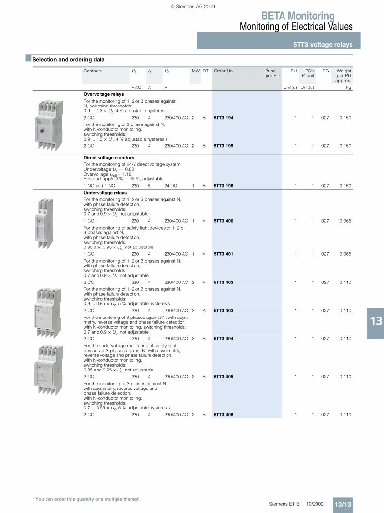
■ Selection and ordering data
Contacts Ue Ie Uc MW DT Order No. Priceper PU
PU PS*/P. unit
PG Weightper PU
approx.
V AC A V Unit(s) Unit(s) kg
Overvoltage relays
For the monitoring of 1, 2 or 3 phases against N, switching thresholds: 0.9 ... 1.3 × Uc, 4 % adjustable hysteresis
2 CO 230 4 230/400 AC 2 B 5TT3 194 1 1 027 0.150
For the monitoring of 3 phase against N, with N-conductor monitoring, switching thresholds: 0.9 ... 1.3 × Uc, 4 % adjustable hysteresis
2 CO 230 4 230/400 AC 2 B 5TT3 195 1 1 027 0.150
Direct voltage monitors
For the monitoring of 24-V direct voltage system;Undervoltage Uoff = 0.82Overvoltage Uoff = 1.18Residual ripple 0 % ... 15 %, adjustable
1 NO and 1 NC 230 5 24 DC 1 B 5TT3 196 1 1 027 0.150
Undervoltage relays
For the monitoring of 1, 2 or 3 phases against N, with phase failure detection, switching thresholds: 0.7 and 0.9 × Uc, not adjustable
1 CO 230 4 230/400 AC 1 } 5TT3 400 1 1 027 0.065
For the monitoring of safety light devices of 1, 2 or 3 phases against N, with phase failure detection, switching thresholds: 0.85 and 0.95 × Uc, not adjustable
1 CO 230 4 230/400 AC 1 } 5TT3 401 1 1 027 0.065
For the monitoring of 1, 2 or 3 phases against N,with phase failure detection, switching thresholds: 0.7 and 0.9 × Uc, not adjustable
2 CO 230 4 230/400 AC 2 } 5TT3 402 1 1 027 0.110
For the monitoring of 1, 2 or 3 phases against N,with phase failure detection, switching thresholds: 0.9 ... 0.95 × Uc, 5 % adjustable hysteresis
2 CO 230 4 230/400 AC 2 A 5TT3 403 1 1 027 0.110
For the monitoring of 3 phases against N, with asym-metry, reverse voltage and phase failure detection, with N-conductor monitoring, switching thresholds: 0.7 and 0.9 × Uc, not adjustable
2 CO 230 4 230/400 AC 2 B 5TT3 404 1 1 027 0.110
For the undervoltage monitoring of safety light devices of 3-phases against N, with asymmetry, reverse voltage and phase failure detection, with N-conductor monitoring, switching thresholds: 0.85 and 0.95 × Uc, not adjustable
2 CO 230 4 230/400 AC 2 B 5TT3 405 1 1 027 0.110
For the monitoring of 3 phases against N, with asymmetry, reverse voltage and phase failure detection, with N-conductor monitoring, switching thresholds: 0.7 ... 0.95 × Uc, 5 % adjustable hysteresis
2 CO 230 4 230/400 AC 2 B 5TT3 406 1 1 027 0.110
ET_B1_2009-06_UEB_en.book Page 13 Montag, Dezember 7, 2009 1:05 PM
© Siemens AG 2009

BETA MonitoringMonitoring of Electrical Values
5TT3 voltage relays
13/14 Siemens ET B1 · 10/2009* You can order this quantity or a multiple thereof.
13■ Characteristic curves
Contacts Ue Ie Uc MW DT Order No. Priceper PU
PU PS*/P. unit
PG Weightper PU
approx.
V AC A V AC Unit(s) Unit(s) kg
Short-time relays
For the monitoring of short-time failure detection ≥ 20 ms of 1, 2 or 3 phases against N, with phase failure detection and N-conductor monitoring,switching thresholds: 0.8 ... 0.85 × Uc, not adjustable
2 CO 230 4 230/400 2 B 5TT3 407 1 1 027 0.110
Under and overvoltage relays
For the monitoring of 3 phases against N, with asymmetry, reverse voltage and phase failure detection, with N-conductor monitoring and adjust-able time delay of 0.1 ... 20 s, switching thresholds: Undervoltage: 0.7 ... 1.1 × Uc, 4 % adjustable hysteresis Overvoltage: 0.9 ... 1.3 × Uc, 4 % adjustable hysteresis
2 CO 230 4 230/400 2 B 5TT3 408 1 1 027 0.110
N-conductor monitors
With asymmetry detection and N-conductor monitoring
2 CO 230 4 230/400 2 B 5TT3 410 1 1 027 0.110
Voltage relay for the overvoltage monitoring of medical premises
Single-phase against N With test button, switching thresholds: 0.9 × Un, 2 % hysteresis
2 NO, 2 NC 230 4 230 4 C 5TT3 411 1 1 027 0.220
Single, two or three-phase against N, with asymmetry, reverse voltage and phase failure detection, with N-conductor monitoring, and one test button each for the phases, switching thresholds: 0.9 × Un, 4 % hysteresis
1 CO, 1 NO, 1 NC 230 4 230/400 4 C 5TT3 412 1 1 027 0.230
Timing interval of 5TT3 400 ... 5TT3 406 undervoltage relays
Timing interval of 5TT3 410 N conductor monitors
11-14
Uab
L1L2L3
Uc
11-12
Uab= Release value
I2_0
7033
b
11-1411-12
L1, L2, L3
C
N
I2_07516b
PEN conductorinterruption
ET_B1_2009-06_UEB_en.book Page 14 Montag, Dezember 7, 2009 1:05 PM
© Siemens AG 2009

BETA MonitoringMonitoring of Electrical Values
5TT3 voltage relays
13/15Siemens ET B1 · 10/2009
13
5TT3 411 and 5TT3 412 voltage relays
For characteristic curves of the 5TT3 411 and 5TT3 412 voltage relays, see "Monitoring of medical premises" on page 13/33.
■ Dimensional drawings
5TT3 4, 5TT3 194 and 5TT3 195 voltage relays
5TT3 196 DC voltage controllers
5TT3 411 and 5TT3 412 voltage relaysFor dimensional drawings of the 5TT3 411 and 5TT3 412 voltage relays, see "7LQ3 insulation monitors for medical premises" on page 13/33.
5TT3 410 N-conductor monitors
Timing interval of 5TT3 407 short-time relays
Timing interval of5TT3 408 under/overvoltage relays
tv: adjustable automatic reclosing delay 0.2 to 20 s t: adjustable OFF delay 0.1 to 20 s
The undervoltage relay switches at a phase asymmetry of approx. 6 to 8 %, regardless of the response values for undervoltage. The above diagram shows the timing interval for undervoltage or asymmetry.
The undervoltage relay switches at a phase asymmetry of approx. 6 to 8 %, regardless of the response values for undervoltage. The above diagram shows the timing interval for undervoltage.
5TT3 400 5TT3 401
5TT3 402 5TT3 403
5TT3 404 5TT3 405 5TT3 407 5TT3 408
5TT3 1945TT3 195 5TT3 406
� � � � � � � � �
� � �
� � � �
��
� � � �
� � � �
�
�
� � �
� � � �
�
� � � � � � � � � �
� � � � � � � � � � � � � � � � � � � �
� � � � � � � � � � � � � � � � � � � �
� � � � � � � � � � � � �
� � � � � �
� � � � � � � � � �
� � � � � �
� � � � � � � � � �
� ! " ! # � ! " ! #
� � � � � � � � $
� � �
� � � �
% �
�
� &
�
% � �
% �
% � �
% �
% � �
' �
( �
( �
' �
��
) � * � ) � * � ) +
) ! ,
) ! ,
) ! ,
� � �
� �
� �
& - � � � � � �
& - � � � � � �
L1 L2 L3 N
14 11 24 21
12 22
L1 L2 L3 N
14 11 24 21
12 22
18 36 36 36
L1 L2
L1
14 11
12
14 11 24 21
12 22
L1 L2 L3N
5 4364
45 90
I2_1
1515
4355
45 90
I2_06552518
e+ f
23
11 12
24
L1 L2 L3 N
14 11 24 21
12 22
36 5 4364
45 90
I2_1
1516
ET_B1_2009-06_UEB_en.book Page 15 Montag, Dezember 7, 2009 1:05 PM
© Siemens AG 2009
BETA MonitoringMonitoring of Electrical Values
5TT3 voltage relays
13/16 Siemens ET B1 · 10/2009
13
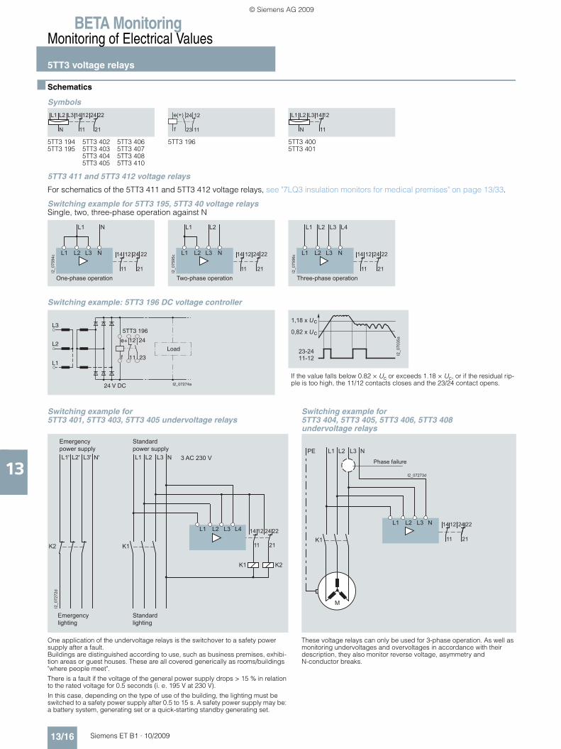
■ Schematics
Symbols
5TT3 411 and 5TT3 412 voltage relays
For schematics of the 5TT3 411 and 5TT3 412 voltage relays, see "7LQ3 insulation monitors for medical premises" on page 13/33.
Switching example for 5TT3 195, 5TT3 40 voltage relaysSingle, two, three-phase operation against N
Switching example: 5TT3 196 DC voltage controller
5TT3 194 5TT3 195
5TT3 402 5TT3 403 5TT3 404 5TT3 405
5TT3 406 5TT3 407 5TT3 408 5TT3 410
5TT3 196 5TT3 400 5TT3 401
11
1214
21
2224L3L2L1
N 23
1224
11
e(+)
f 11
1214L3L2L1
N
14 12 24 22
11 21I2_0
7594
c L1 L2 L3 N
L1 N
One-phase operation
14 12 24 22
11 21I2_0
7595
c L1 L2 L3 N
L1 L2
Two-phase operation
14 12 24 22
11 21I2_0
7596
c L1 L2 L3 N
L1 L3 L4L2
Three-phase operation
If the value falls below 0.82 × Uc or exceeds 1.18 × Uc, or if the residual rip-ple is too high, the 11/12 contacts closes and the 23/24 contact opens.
Switching example for 5TT3 401, 5TT3 403, 5TT3 405 undervoltage relays
Switching example for 5TT3 404, 5TT3 405, 5TT3 406, 5TT3 408 undervoltage relays
One application of the undervoltage relays is the switchover to a safety power supply after a fault. Buildings are distinguished according to use, such as business premises, exhibi-tion areas or guest houses. These are all covered generically as rooms/buildings "where people meet".
There is a fault if the voltage of the general power supply drops > 15 % in relation to the rated voltage for 0.5 seconds (i. e. 195 V at 230 V).
In this case, depending on the type of use of the building, the lighting must be switched to a safety power supply after 0.5 to 15 s. A safety power supply may be: a battery system, generating set or a quick-starting standby generating set.
These voltage relays can only be used for 3-phase operation. As well as monitoring undervoltages and overvoltages in accordance with their description, they also monitor reverse voltage, asymmetry and N-conductor breaks.
5TT3 196
L1
L2
L3
e+
f
I2_07274a
11
12
23
24
Load
24 V DC
����������
�
�
��
�
��
��������
�������
14 12 24 22
11 21
L1' L2' L3' N'
I2_0
7272
d
L1 L2 L3 L4
K2
L1 L2 L3 N
K1
K1 K2
Emergencypower supply
Standardpower supply
Emergencylighting
Standardlighting
3 AC 230 V
I2_07273d
L1 L2 L3 N
L1 L2 L3 N
K1
14 12 24 22
11 21
M
PE
Phase failure
ET_B1_2009-06_UEB_en.book Page 16 Montag, Dezember 7, 2009 1:05 PM
© Siemens AG 2009

BETA MonitoringMonitoring of Electrical Values
5TT3 voltage relays
13/17Siemens ET B1 · 10/2009
13
Switching example for 5TT3 407 short-time relays
Switching example for 5TT3 407 short-time relays
In the case of sensitive technical sequences, it is often not possible to tell whether this interrupt has interfered with the process sequence. The switch disconnects the power supply, which can then be switched back by using the reset pushbutton.
In simple cases, it may be sufficient that a short-time interrupt is registered without the need to disconnect the power supply. In this case, the duration is counted by the pulse counter. The pulse counter can be reset if required.
14 12 24 22
11 21
I2_07597c
L1 L2 L3 N
L1 L2 L3 N
K1 K1
Reset
3 AC 230 V
14 12 24 22
11 21
L1 L2 L3 N
L1 L2 L3 N
1 2 3 4
5TT3 407 7KT5 883
I201
_075
98b
Reset
3 AC 230 V
Switching example of 5TT3 410 N-conductor monitors
L1
5TT3 410
L2 L3
N
K1
L1
L2L3NPE
F1
F2F3
S1 F4 F5 F6
11
14
K1 I2_07517a
Test and serviceswitch
ET_B1_2009-06_UEB_en.book Page 17 Montag, Dezember 7, 2009 1:05 PM
© Siemens AG 2009

BETA MonitoringMonitoring of Electrical Values
5TT3 voltage relays
13/18 Siemens ET B1 · 10/2009
13
■ More information
General voltage monitoring
For general device and plant protection, voltage relays with switching thresholds of 0.7 × Uc, i. e. 161 V are used. If they have fixed, unchangeable switching thresholds, they switch back to normal operation at 0.85 × Uc, 195 V or at 0.9 × Uc, 207 V, depending on the version. If they have adjustable thresh-old values, they switch back to normal operation with 4 % hys-teresis, 9 V.
1, 2 or 3 phases against N or 3 phases against N
All voltage relays require an N-conductor. Devices for single, two or three phases against N can be used for single, two, or three-phase operation. Devices for 3 phases against N require all three phases, whereby the sequence in which they are con-nected is irrelevant.
Asymmetry detection
If different voltages occur in a three-phase network, this is called phase asymmetry. Some voltage relays detect an asymmetry of approx. 6 to 8 % of the phase-to-neutral voltage, i. e. approx. 14 to 16 V and switch off. This type of operation is used to protect motors against a "skew" (for example).
N-conductor monitoring
An N-conductor break causes a skew, depending on the phase load. In extreme cases, this could cause 400 V to be applied to a phase, which would destroy any connected devices. Each voltage relay with asymmetry detection is tripped by an N-con-ductor break, if the phase displacement is at least 14 to 18 V.
The 5TT3 410 N-conductor monitor detects a phase displace-ment of 5 %, which is roughly 12 V. This provides earlier protec-tion against overvoltage for connected devices. The N-conduc-tor monitor does not react if the voltage drops or rises in all phases simultaneously; or if a phase is swapped with the N-conductor.
Reverse voltage detection
If a phase fails, the motors feed a reverse voltage to the missing phase. However, in this case, voltage relays with reverse voltage detection will disconnect because they are monitoring the phase angle.
Phase failure detection
If a phase fails completely, the voltage relays disconnect with a delay as specified in the technical specifications.
Short-time failure detection
Short-time failures upwards of 20 ms cannot be detected with conventional voltage relays. However, they can occur in the case of system transfers or lightning strikes and can lead to uncer-tainty for sensitive process sequences or measuring proce-dures. The 5TT3 407 short-time voltage relay has a reset func-tion that allows a procedure to be permanently interrupted after a fault.
Back-up fuse
The voltage relays do not require a back-up fuse as device pro-tection. However, they are often installed in junctions, i. e. in main supply systems with high fusing. In this case, the supply lead to the voltage relay must be short-circuit resistant. The back-up fuse only serves as line protection.
5TT3 411 and 5TT3 412 voltage relays
For control elements of the 5TT3 411 and 5TT3 412 voltage relays, see "Monitoring of medical premises" on page 13/33.
5TT3 194
5TT3 195
5TT3 196
5TT3 400
5TT3 401
5TT3 402
5TT3 403
5TT3 404
5TT3 405
5TT3 406
5TT3 407
5TT3 408
5TT3 410
5TT3 411
5TT3 412
Overvoltage ✓ ✓ ✓ -- -- -- -- -- -- -- -- ✓ -- ✓ ✓
Undervoltage -- -- ✓ ✓ ✓ ✓ ✓ ✓ ✓ ✓ ✓ ✓ -- -- --
Monitoring of safety light devices -- -- -- -- ✓ -- -- -- ✓ -- -- -- -- -- --
Monitoring of medical premises -- -- -- -- -- -- -- -- -- -- -- -- -- ✓ ✓
Monitoring of N-conductor -- -- -- -- -- -- -- -- -- -- -- -- ✓ -- ✓
Monitoring of short-time interruptions -- -- -- -- -- -- -- -- -- -- ✓ -- -- -- --
1, 2, 3 phases against N ✓ -- -- ✓ ✓ ✓ ✓ -- -- -- ✓ -- -- ✓ ✓
3 phases against N -- ✓ -- -- -- -- -- ✓ ✓ ✓ -- ✓ -- -- --
Asymmetry detection -- ✓ -- -- -- -- -- ✓ ✓ ✓ -- ✓ ✓ -- ✓
N-conductor monitoring -- -- -- -- -- -- -- ✓ ✓ ✓ ✓ ✓ ✓ -- ✓
Reverse voltage detection -- ✓ -- -- -- -- -- ✓ ✓ ✓ -- ✓ -- -- ✓
Short-time failure detection -- -- -- -- -- -- -- -- -- -- ✓ -- -- -- --
Phase failure detection -- -- -- ✓ ✓ ✓ ✓ ✓ ✓ ✓ ✓ ✓ -- -- ✓
Switching thresholds: -- -- -- -- -- -- -- -- -- -- -- -- -- -- --
0.7/0.9 × Uc, not adjustable -- -- -- ✓ -- ✓ -- ✓ -- -- -- -- -- -- --
0.8/0, 85 × Uc, not adjustable -- -- -- -- -- -- -- -- -- -- ✓ -- -- -- --
0.85/0.95 × Uc, not adjustable -- -- -- -- ✓ -- ✓ -- ✓ -- -- -- -- -- --
0.7 ... 0.95 × Uc, 5 % hysteresis, adjustable -- -- -- -- -- -- -- -- -- ✓ -- -- -- -- --
0.7 ... 1.1 × Uc, 4 % hysteresis, adjustable -- -- -- -- -- -- -- -- -- -- -- ✓ -- -- --
0.9 ... 1.3 × Uc, 4 % hysteresis, adjustable ✓ ✓ -- -- -- -- -- -- -- -- -- ✓ -- -- --
Adjustable time delay -- -- -- -- -- -- -- -- -- -- -- ✓ -- -- --
Contact: 1 CO contact -- -- -- ✓ ✓ -- -- -- -- -- -- -- -- -- --
Contact: 2 CO contacts ✓ ✓ -- -- -- ✓ ✓ ✓ ✓ ✓ ✓ ✓ ✓ -- --
Contact: 1 CO contact, 1 NO contact, 1 NC contact
-- -- -- -- -- -- -- -- -- -- -- -- -- -- ✓
Contact: 1 NO contact, 1 NC contact -- -- ✓ -- -- -- -- -- -- -- -- -- -- -- --
Contact: 2 NO contacts, 2 NC contacts -- -- -- -- -- -- -- -- -- -- -- -- -- ✓ --
ET_B1_2009-06_UEB_en.book Page 18 Montag, Dezember 7, 2009 1:05 PM
© Siemens AG 2009

BETA MonitoringMonitoring of Electrical Values
5TT6 current relays
13/19Siemens ET B1 · 10/2009
13
■ OverviewCurrent relays monitor single and three-phase systems for the flow of current in emergency lighting installations and the load of motors. They are available as undercurrent, overcurrent and un-der/overcurrent relays.
■ Benefits• Devices with an extremely broad range of applications of min-
imum 0.1 A to maximum 15 A without transformer• Permanent overload capability up to 20 A or 30 A may, for up
to 3 seconds, protect the function against uncontrolled plant states and increase plant availability
• Range changing enables the precise setting of current values through a high resolution
• Ultra compact current relays require only the smallest of spaces and save costs.
■ Technical specifications
5TT6 111 5TT6 112Standards IEC 60255; DIN VDE 0435-303Rated control current Ic A 1 ... 10Rated control voltage Uc V AC 230Operating range × Uc 0.9 ... 1.1Overload capability, continuous A 15Overload capability, short-time At 50 °C ambient temp. max. 3 s A 20
Rated frequency Hz 50/60Response values ON-switching Infinitely variable
OFF-switching Fixed, 4 % hysteresis
Switching delay tv Infinitely adjustable s 0.1 ... 20Response time Non-adjustable ms Current corresponds to the rated operational power of the
continuous-flow heater
Minimum contact load V; mA 10; 100Rated insulation voltage Ui Between coil/contact kV 2.5Contactsμ contact (AC-15) NO contacts A 3
NC contacts A 1
Electrical isolation Creepage distances and clearances
mm 3
Actuator/contact
Rated impulse withstand voltage Uimp Actuator/contact kV > 4Terminals ± screw (Pozidriv) 1Conductor cross-sections Rigid max. mm2 2 × 2.5
Flexible, with end sleeve min. mm2 1 × 0.5
Permissible ambient temperature °C -20 ... +60Resistance to climate Acc. to EN 60068-1 20/60/4
5TT6 113 5TT6 114 5TT6 115 5TT6 120
Standards IEC 60255; DIN VDE 0435-303
Rated control current Ic 4 ranges 1 rangeA 0.1 ... 1 0.5 ... 5A 0.5 ... 5A 1 ... 10A 1.5 ... 15
Rated control voltage Uc V AC 230
Operating range × Uc 0.9 ... 1.1Overload capability, continuous A 20 15Overload capability independent of measuring range
A 30Max. 3 s
Rated frequency Hz 50/60
Response values ON-switching Infinitely variableOFF-switching Fixed, 4 % hysteresis
Switching delay tv Infinitely adjustable s 0.1 ... 20
Response time Non-adjustable ms See page 13/23
Minimum contact load V; mA 10; 100
Rated insulation voltage Ui Between coil/contact kV 2.5
Contactsμ contact (AC-15) NO contacts A 5
NC contacts A 1
Electrical isolation Creepage distances and clearances
mm 3
Actuator/contact
Rated impulse withstand voltage Uimp Actuator/contact kV > 4
Terminals ± screw (Pozidriv) 1
Conductor cross-sections Rigid max. mm2 2 × 2.5Flexible, with end sleeve min. mm2 1 × 0.5
Permissible ambient temperature °C -20 ... +60
Resistance to climate Acc. to EN 60068-1 20/60/4
ET_B1_2009-06_UEB_en.book Page 19 Montag, Dezember 7, 2009 1:05 PM
© Siemens AG 2009
BETA MonitoringMonitoring of Electrical Values
5TT6 current relays
13/20 Siemens ET B1 · 10/2009* You can order this quantity or a multiple thereof.
13
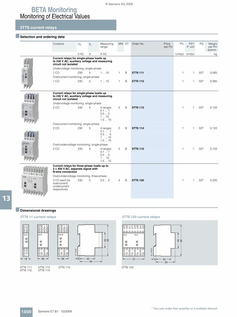
■ Selection and ordering data
■ Dimensional drawings
5TT6 11 current relays 5TT6 120 current relays
Contacts Ue Ie Measuring range
MW DT Order No. Priceper PU
PU PS*/P. unit
PG Weightper PU
approx.
V AC A A AC Unit(s) Unit(s) kg
Current relays for single-phase loads up to 230 V AC, auxiliary voltage and measuring circuit not isolated
Undervoltage monitoring, single-phase
1 CO 230 5 1 ... 10 1 B 5TT6 111 1 1 027 0.065
Overcurrent monitoring, single-phase
1 CO 230 5 1 ... 10 1 B 5TT6 112 1 1 027 0.065
Current relays for single-phase loads up to 230 V AC, auxiliary voltage and measuring circuit not isolated
Undervoltage monitoring, single-phase
2 CO 230 5 4 ranges 2 B 5TT6 113 1 1 027 0.1220.1 ... 10.5 ... 51 ... 101.5 ... 15
Overcurrent monitoring, single-phase
2 CO 230 5 4 ranges 2 B 5TT6 114 1 1 027 0.1220.1 ... 10.5 ... 51 ... 101.5 ... 15
Over/undervoltage monitoring, single-phase
2 CO 230 5 4 ranges 2 B 5TT6 115 1 1 027 0.1220.1 ... 10.5 ... 51 ... 101.5 ... 15
Current relays for three-phase loads up to 3 × 400 V AC, separate signal with N-wire connection
Over/undervoltage monitoring, three-phase
2 CO each for overcurrent/undercurrent respectively
230 5 0.5 ... 5 4 B 5TT6 120 1 1 027 0.220
5TT6 111 5TT6 112
5TT6 113 5TT6 114
5TT6 115 5TT6 120
3618
A2A1
1412
11
N
11
12
14
Z3Z2
ki
21
22
24
Z4Z1
L/i L/i
L/k
36
A2A1
11
12
14
Z3Z2
ki
21
22
24
Z4Z1
5 4364
45 90
I2_1
1518
5 4355
45 90
I2_1
1517
A2A1
11
12
14
k1i1
21
22
24
72
A2A1
31
32
34
k3i3
41
42
44
ET_B1_2009-06_UEB_en.book Page 20 Montag, Dezember 7, 2009 1:05 PM
© Siemens AG 2009

BETA MonitoringMonitoring of Electrical Values
5TT6 current relays
13/21Siemens ET B1 · 10/2009
13
■ Schematics
Symbols
5TT6 111 5TT6 112
5TT6 113 5TT6 114 5TT6 115 5TT6 120
ki
N
14 12
11
L L>I
ki
Z1 Z2 Z3 Z4
14 12 24 22
11 21
A2A1>I
ki
Z1 Z2 Z3 Z4
14 12 24 22
11 21
A2A1<I
ki
Z1 Z2 Z3 Z4
14 12 24 22
11 21
A2A1><I
34 32 44 42
31 41
A2A1
i1-i3 k1-k3
14 12 24 22
11 21
>I
<I
Switching example: 5TT6 111 undervoltage monitoring
Switching example: 5TT6 114 overcurrent monitoring measurement with transformer
L/i N
L1
N
12 14
11L/kTo the 5TT3 460 or 5TT3 461 faultsignaling relay
230 V AC I2_07522b
i
5TT6 114
A1 A2
k
K1
PEM
L1
L2L3NPE
K1
12 14 22 24
11 21
3 AC 230/400 V I2_07560a
ET_B1_2009-06_UEB_en.book Page 21 Montag, Dezember 7, 2009 1:05 PM
© Siemens AG 2009
BETA MonitoringMonitoring of Electrical Values
5TT6 current relays
13/22 Siemens ET B1 · 10/2009
13
■ More information
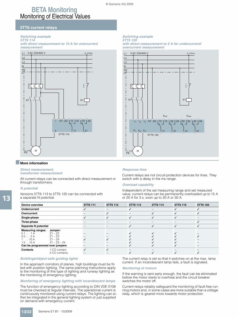
Direct measurement, transformer measurement
All current relays can be connected with direct measurement or through transformers.
N potential
Versions 5TT6 113 to 5TT6 120 can be connected with a separate N potential.
Response time
Current relays are not circuit-protection devices for lines. They switch with a delay in the ms range.
Overload capability
Independent of the set measuring range and set measured value, current relays can be permanently overloaded up to 15 A or 20 A for 3 s, even up to 20 A or 30 A.
Buildings/object-safe guiding lights
In the approach corridors of planes, high buildings must be fit-ted with position lighting. The same planning instructions apply to the monitoring of this type of lighting and runway lighting as the monitoring of emergency lighting.
Monitoring of emergency lighting with incandescent lamps
The function of emergency lighting according to DIN VDE 0108 must be checked at regular intervals. The operational current is continuously monitored using current relays. The lighting can ei-ther be integrated in the general lighting system or just supplied on demand with emergency current.
The current relay is set so that it switches on at the max. lamp current. If an incandescent lamp fails, a fault is signaled.
Monitoring of motors
If the warning is sent early enough, the fault can be eliminated before the motor starts to overheat and the circuit breaker switches the motor off.
Current relays reliably safeguard the monitoring of fault-free run-ning motors and, in some cases are more suitable than a voltage relay, which is geared more towards motor protection.
Switching example 5TT6 114 with direct measurement to 15 A for overcurrent measurement
Switching example 5TT6 120 with direct measurement to 5 A for undercurrent/overcurrent measurement
i
5TT6 114
A1 A2
k
K1
PEM
L1
L2L3NPE
K1
12 14 22 24
11 21
3 AC 230/400 V I2_07559a
5TT6 120
A1 A2
K1
PEM
L1
L2L3NPE
K1
12 14 22 24
11 21
i
k
1 i2 i3
k2 k31
32 34 42 44
31 41
Imin Imax
3 AC 230/400 V I2_07561a
Device overview 5TT6 111 5TT6 112 5TT6 113 5TT6 114 5TT6 115 5TT6 120
Undercurrent ✓ -- ✓ -- ✓ ✓
Overcurrent -- ✓ -- ✓ ✓ ✓
Single-phase ✓ ✓ ✓ ✓ ✓ --
Three-phase -- -- -- -- -- ✓
Separate N potential -- -- ✓ ✓ ✓ ✓
Measuring ranges: Jumper:0.1 ... 1 A Z1 – Z2 -- -- ✓ ✓ ✓ --0.5 ... 5 A Z1 – Z3 -- -- ✓ ✓ ✓ ✓1 ... 10 A Z1 – Z4 ✓ ✓ ✓ ✓ ✓ --1.5 ... 15 A Z1 – Z3 – Z4 -- -- ✓ ✓ ✓ --Can be programmed over jumpers -- -- ✓ ✓ ✓ --
Contacts 1 CO contact ✓ ✓ -- -- -- --2 CO contacts -- -- ✓ ✓ ✓ ✓
ET_B1_2009-06_UEB_en.book Page 22 Montag, Dezember 7, 2009 1:05 PM
© Siemens AG 2009
BETA MonitoringMonitoring of Electrical Values
5TT6 current relays
13/23Siemens ET B1 · 10/2009
13
Example: screw conveyor
Hard objects in screw conveyors, e. g. in sewage treatment plants, often lead to a blockage in the conveyor system. Appropriately set, the current relay signals over its contact(s) that a hazardous situation has occurred and threatens to block the motor.
Example: stirrer
As with the conveyor processes, changes to the viscosity can lead to an overload of the motors.
Example: crane motor control system
The current monitoring of the main motor (hoisting motor) en-sures that the electrical holding brake is not released until the main motor is in operation and the load is held.
Example: dust extraction
In the interests of work safety and to protect against massive dust development, it is essential to ensure that the dust extrac-tion system is working perfectly before a saw or sanding ma-chine is switched on.
Planning the monitoring of an incandescent lamp
Current relays have a hysteresis of approx. 4 %. The smallest lamp must not exceed the set measuring range by more than 8 %.
Example: 12 lamps à 100 W = 1200 W, which corresponds to a current of approx. 5.2 A. If a lamp fails, the current drops by 0.4 A. This 0.4 A corresponds to 8 % of the set measured value 5.2 A.
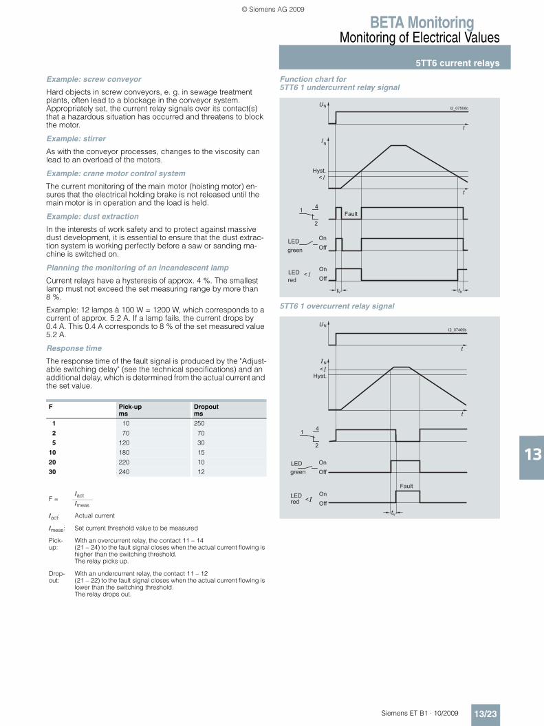
Response time
The response time of the fault signal is produced by the "Adjust-able switching delay" (see the technical specifications) and an additional delay, which is determined from the actual current and the set value.
Function chart for 5TT6 1 undercurrent relay signal
5TT6 1 overcurrent relay signal
F Pick-up Dropoutms ms
1 10 250
2 70 70
5 120 30
10 180 15
20 220 10
30 240 12
F =Iact
Imeas
Iact: Actual current
Imeas: Set current threshold value to be measured
Pick-up:
With an overcurrent relay, the contact 11 – 14 (21 – 24) to the fault signal closes when the actual current flowing is higher than the switching threshold. The relay picks up.
Drop-out:
With an undercurrent relay, the contact 11 – 12 (21 – 22) to the fault signal closes when the actual current flowing is lower than the switching threshold. The relay drops out.
� � � � � � � �
�
�
� �
�
� �
� �
� �
�
��
�
� �
�
� � � �
�
�
�
� � � � �
� � �
� � � � �
� � � � �
� � � � � � ! "
�
�
�
� �
�
� �
� �
� �
�
��
�
�
�
�
#
� � � � �
� � �
� � � � �
� � � � �
ET_B1_2009-06_UEB_en.book Page 23 Montag, Dezember 7, 2009 1:05 PM
© Siemens AG 2009

BETA MonitoringMonitoring of Electrical Values
5TT6 current relays
13/24 Siemens ET B1 · 10/2009
13
Function chart for 5TT6 115 under/overcurrent relay signal
Contrary to all other current relays, a fault signal is always output over the contact 11 – 14 (21 – 24). The red LEDs indicate whether the signal is for an undercurrent or an overcurrent.
I2_07472b
On
t
�
Off
On
OffLED
LED
t
t
1 4
2
On
OffLED
N
N
tvv tv
green
red
red
Fault Fault
Hyst.
Hyst.
ET_B1_2009-06_UEB_en.book Page 24 Montag, Dezember 7, 2009 1:05 PM
© Siemens AG 2009

BETA MonitoringMonitoring of Electrical Values
5TT6 priority switches
13/25Siemens ET B1 · 10/2009* You can order this quantity or a multiple thereof.
13
■ Overview
In the mixed operation of electric hot water and electric storage heaters, the priority switch interrupts the charging procedure of the storage heater if hot water is required during the low-tariff time, thus limiting the connected load in compliance with BTO § 6. The control circuit terminals must be sealable.
■ Benefits
Reduction of the connection fee, which depends on the maxi-mum load to be supplied (BTO, German Federal Regulation on Tariffs § 6 Subsection 4), when used in systems with continuous-flow heaters and electric storage heaters where the continuous-flow heaters are switched with priority.
■ Technical specifications
■ Selection and ordering data
■ Dimensional drawings ■ Schematics
Symbols
5TT6 101 5TT6 102 5TT6 103
Standards EN 60669 (VDE 0632), BTO § 6 Subsection 4
Rated control current Ic A 40 54 6 ... 40 (Current corresponds to the rated operational power of the continuous-flow heater).
Rated frequency Hz 50
Response currents A 13 23 6(Continuous rise not permissible)
Rated operational powerFor continuous-flow heaters Up to 230 V AC kW 9 12 1.5 ... 9
Up to 3 × 230 V AC kW 27 36 4.5 ... 27
Rated impulse withstand voltage Uimp kV > 2.5
Rated operational voltage Ue V AC 250
Rated operational current Ie At Ue = 230 V AC A 1
Terminals ± screw (Pozidriv) 1
Conductor cross-sections• Coil For conductor cross-
sections up tomm2 10
• Contacts For conductor cross-sections up to
mm2 2 × 2.5
Permissible ambient temperature °C -20 ... +40
Resistance to climate Acc. to DIN 50016 FW 24
Ue Ie Response currents
MW DT Order No. Priceper PU
PU PS*/P. unit
PG Weightper PU
approx.
V AC A A Unit(s) Unit(s) kg
5TT6 101
Priority switches
For continuous-flow heaters up to 27 kW
230 40 13 1 } 5TT6 101 1 1 027 0.100
For continuous-flow heaters up to 33 kW
230 54 23 1 B 5TT6 102 1 1 027 0.100
For electronically controlled continuous-flow heaters up to 27 kW
230 40 6 ... 40 1 } 5TT6 103 1 1 027 0.100
5TT6 101, 5TT6 102, 5TT6 103
18
45 86
44555
I2_0
6544
bi11
12k
5TT6 101, 5TT6 102, 5TT6 103
11
12
k
i>I
ET_B1_2009-06_UEB_en.book Page 25 Montag, Dezember 7, 2009 1:05 PM
© Siemens AG 2009

BETA MonitoringMonitoring of Electrical Values
5TT3 fuse monitors
13/26 Siemens ET B1 · 10/2009* You can order this quantity or a multiple thereof.
13
■ Overview
Fuse monitors serve to monitor all types and versions of melting fuses that cannot be equipped with a fault signal contact. This enables integration in fault signaling circuits or a central alarm in order to improve plant availability.
■ Benefits
• Increase in plant availability because fuse failures – which could cause considerable damage to the plant – are detected in plenty of time.
• A fuse failure is detected even if the load is switched off. This ensures the highest level of plant availability.
■ Technical specifications
■ Selection and ordering data
■ Dimensional drawings ■ Schematics
Symbols
5TT3 170
Standards IEC 60255; DIN VDE 0435-110
Rated control voltage Uc V 3 AC 380 ... 415
Operating range × Uc 0.8 ... 1.1
Rated frequency Hz 50 ... 400
Internal resistance of measuring paths Ω/V > 1000
Max. permissible rear feed % 90
Response/release time ms < 50
Rated impulse withstand voltage UimpInput/output
kV > 4
Rated operational voltage Ue V AC 250
Rated operational current Ie AC-1 A 4
Electrical service life AC-11 In switching cycles at 1 A 1.5 × 10⁵
Terminals ± screw (Pozidriv) 1
Conductor cross-sections Rigid, max. mm2 2 × 2.5Flexible, with end sleeve, min. mm2 1 × 0.5
Permissible ambient temperature °C -20 ... +45
Resistance to climate Acc. to EN 60068-1 20/45/4
Ue Ie Uc MW DT Order No. Priceper PU
PU PS*/P. unit
PG Weightper PU
approx.
V AC A 3 V AC Unit(s) Unit(s) kg
Fuse monitors
For all low-voltage fuse systems. Can be used in asymmetric systems afflicted with harmonics and regenerative feedback motors. Signal also for disconnected loads.
230 4 380 ... 415 2 } 5TT3 170 1 1 027 0.150
36
L1 L2 L3
14
L1 L2 L3
15
5 4364
45 90
I2_1
1512
L3L2 14L1
13L3'L2'L1'
ET_B1_2009-06_UEB_en.book Page 26 Montag, Dezember 7, 2009 1:05 PM
© Siemens AG 2009

BETA MonitoringMonitoring of Electrical Values
5TT3 fuse monitors
13/27Siemens ET B1 · 10/2009
13
■ More information
Switching example, function chart
If the fuse fails, the motor is immediately disconnected (preven-tion of two-phase run). After changing the fuse, the motor can be restarted by pressing the "ON" button.Unlike conventional motor circuit breakers, it is not possible to switch the motor on if the fuse is faulty.Note:The internal resistance of the measuring paths of the fuse moni-tor is in the MΩ range so that the VDE regulations with regard to touch voltage are met in the event of faulty fuses (> 1000 Ω/V). To isolate the main switch, it must be switched off. The enclosed label should be affixed to the switchgear as a reminder.
M
N
L2
L1 L2 L3
13
I2_07251b
3 ~
L1 L3
L2' 14L1' L3'
L
F1 F2 F3
3 AC 400 V
Off
On
��������
����� �
���
��
ET_B1_2009-06_UEB_en.book Page 27 Montag, Dezember 7, 2009 1:05 PM
© Siemens AG 2009

BETA MonitoringMonitoring of Electrical Values
5TT3 phase and phase sequence monitors
13/28 Siemens ET B1 · 10/2009* You can order this quantity or a multiple thereof.
13
■ Overview
Phase monitors monitor the voltages in three-phase system and signal the power failure of one or more phases over a floating contact. Phase sequence monitors monitor the phase sequence in three-phase systems and signal any changes in the phase se-quence – change of rotating field – over a floating changeover contact.
■ Benefits
• The three-phase LED display in the phase monitor and the LED display in the phase sequence monitors provide constant information on the switching state of the plant
• The compact design in 1 MW saves space.
■ Technical specifications
■ Selection and ordering data
5TT3 421 5TT3 423
Standards IEC 60255; DIN VDE 0435
Rated control voltage Uc V AC 230/400 400
Operating range × Uc 0.8 ... 1.1
Rated frequency Hz 50/60
Rated power dissipation Pv Electronics VA 9Contacts VA 0.2
Rated operational voltage Ue V AC 250
Rated operational current Ie A 4
Minimum contact load V; mA 10; 100
Rated insulation voltage Ui Between coil/contact kV 4
Contacts μ contact (AC-11) A 3
Electrical isolation Creepage distances and clearancesActuator/contact mm 4
Rated impulse withstand voltage Uimp Actuator/contact kV > 2.5
Terminals ± screw (Pozidriv) 1
Conductor cross-sections Rigid, max. mm2 2 × 2.5Flexible, with end sleeve, min. mm2 –
Degree of protection Acc. to EN 60529 IP20, with connected conductors
Safety class Acc. to EN 61140/ VDE 0140-1 II
Permissible ambient temperature °C -20 ... +60
Resistance to climate Acc. to EN 60068-1 20/60/4
Contacts Ue Ie Uc MW DT Order No. Priceper PU
PU PS*/P. unit
PG Weightper PU
approx.
V AC A V AC Unit(s) Unit(s) kg
Phase monitors
With 3 green LEDs for 3 phases
1 CO 250 4 230/400 1 } 5TT3 421 1 1 027 0.060
Phase sequence monitors
With one green LED, which lights up for right-rotating field
1 CO 250 4 400 1 } 5TT3 423 1 1 027 0.050
ET_B1_2009-06_UEB_en.book Page 28 Montag, Dezember 7, 2009 1:05 PM
© Siemens AG 2009

BETA MonitoringMonitoring of Electrical Values
5TT3 phase and phase sequence monitors
13/29Siemens ET B1 · 10/2009
13
■ Dimensional drawings ■ Schematics
Symbols
■ More information
Switching examples
5TT3 421 phase monitors
The phase monitor can be operated either in one, two or three-phase operation.
5TT3 423 phase sequence monitors
Phase sequence monitors must always be connected in three-phase.
5TT3 421 5TT3 423
5 4364
45 90
18
I2_1
0780
18
L2
NL1
L3
1114
12
L2
L1
L3
14
12
11
5TT3 421 5TT3 423
14 12
11
L3L2L1
N
1412
11
L3L2L1
14 12
11I2_1
0776
a L1 L2 L3 N
NL1
Single-phase operation
14 12
11I2_1
0777
a L1 L2 L3 N
L1 L2 N
Two-phase operation
14 12
11I2_1
0778
L1 L2 L3 N
L1 L3L2 N
Three-phase operation
I2_10779a
L1 L2 L3
K1
14 12
11
M
L1 L2 L3PE
ET_B1_2009-06_UEB_en.book Page 29 Montag, Dezember 7, 2009 1:05 PM
© Siemens AG 2009

BETA MonitoringMonitoring of Electrical Values
5TT3 insulation monitors
13/30 Siemens ET B1 · 10/2009
13
■ Overview
Insulation monitors are used for the protection of persons against ungrounded systems - IT systems. The insulation resis-tance of the system being monitored is measured against ground.
These types of measurements are specified according to DIN/VDE 0100-410 – Erection of power installations up to 1000 V – Protection against electric shock.
■ Benefits
• The insulation monitoring for AC voltage systems of up to 500 V AC and 1000 Hz enables application in 400 V three-phase systems.
• Easy operation with potentiometers as the set limit value of the insulation resistance is always visible.
• Simple and cost-effective solution for remote signaling and signaling due to option for connecting an external LED and/or external testing and canceling pushbutton
• Simplified planning and logistics as no auxiliary voltage is required for the insulation monitoring of direct voltage systems up to 280 V DC.
■ Technical specifications
5TT3 470 5TT3 471
Rated control voltage Uc V AC 220 ... 240 --V DC -- 12 ... 280
Operating range For AC supply × Uc 0.8 ... 1.1 --For DC supply -- 0.9 ... 1.25
Frequency range for Uc Hz 45 ... 400 --
Rated power dissipation Pv For AC supply VA Approx. 2 --For DC supply W -- Approx. 1
Rated impulse withstand voltage Uimp Terminals A1 to A2 kV < 4 < 4Terminals L to PE kV < 4 < 4Terminals A1, A2 to L, PE kV < 4 < 3Terminals against contacts kV < 6 < 6
Measuring circuit For AC systems For direct voltage systems
Measurement voltage range Umeas V AC 0 ... 500 --V DC -- 12 ... 280
Operating range × Umeas 0 ... 1.1 0.9 ... 1.1
Frequency range for Umeas Hz 10 ... 1000 --
Alarm values Measuring shunt RAL kΩ 5 ... 10 5 ... 200
Setting of alarm value On absolute scale Infinitely variable Infinitely variable
Alternating current internal resistance Internal testing resistor kΩ > 250 --
Direct current internal resistance Internal testing resistor kΩ > 250 --L+ and L- to PE kΩ -- 75 each
Measurement voltage Umeas Internal V DC Approx. 15 --
Max. measurement current Imeas Short circuit mA < 0.1 0.2 ... 4, depending on the voltage
Direct interference voltage Max. permissible V DC 500 --
Response delay At RAL 50 kΩ and 1 μFand ∞ up to 0.9 x Rmeas s < 1.3 0.8and Rmeas from ∞ to 0 Ω s < 0.7 0.4
Switching hysteresis At Rmeas 50 kΩ % 15 10 15
Contacts μ contact 2 CO 2 CO
Rated operational voltage Ue V AC 250 250
Rated operational current Is Thermal current limit Ith A 4 4AC-13 at 24 V DC A -- 3AC-13 at 250 V DC A -- 0.2AC-15 A -- 3AC-15 NO contacts A 5 --AC-15 NC contacts A 2 --
Terminals ± screw (Pozidriv) 2 2
Conductor cross-sections Rigid, max. mm2 2 × 2.5Flexible, with end sleeve, min. mm2 1 × 0.50
Permissible ambient temperature °C -20 ... +60
Degree of protection EN 60529 °C IP20, with connected conductors
Resistance to climate Acc. to EN 60068-1 20/060/04
ET_B1_2009-06_UEB_en.book Page 30 Montag, Dezember 7, 2009 1:05 PM
© Siemens AG 2009

BETA MonitoringMonitoring of Electrical Values
5TT3 insulation monitors
13/31Siemens ET B1 · 10/2009* You can order this quantity or a multiple thereof.
13
■ Selection and ordering data
■ Dimensional drawings
■ More information
Function chartsl
Contacts Uc Ue Measuring range
MW DT Order No. Priceper PU
PU PS*/P. unit
PG Weightper PU
approx.
V AC V kΩ Unit(s) Unit(s) kg
Insulation monitors
For monitoring the insulation resistance in non-grounded AC and three-phase systems from 10 ... 1000 Hz
2 CO 250 0 ... 500 V AC 5 ... 100 2 B 5TT3 470 1 1 027 0.160
For monitoring the insulation resistance in non-grounded DC systems
2 CO 250 12 ... 280 V DC 5 ... 200 2 B 5TT3 471 1 1 027 0.170
5TT3 470 5TT3 471
36
PTPE
L
LT2LT1
11
12
14 21
22
24
A2A1
36
PTPE
L-L+
LTX1
5 4364
45 90
I2_1
1519
11
12
14 21
22
24
5TT3 470, 5TT3 471
�������
��
�
���������
���������
��� ��!"#��$��"�!����%�!���� �
&"!'# !�(� �!��!#$�)�
*�+��,-.�.((
&"!'�(� �!��!#$�)�*���!� !!#�
*�+��,- .�.((
ET_B1_2009-06_UEB_en.book Page 31 Montag, Dezember 7, 2009 1:05 PM
© Siemens AG 2009

BETA MonitoringMonitoring of Electrical Values
5TT3 insulation monitors
13/32 Siemens ET B1 · 10/2009
13
5TT3 470 for AC and three-phase systems 5TT3 471 for direct voltage systems
Front views
Direct interference voltage
While direct interference voltages do not damage the devices they often interfere with conditions in the measuring circuit. In a system being monitored, only one insulation monitor should be connected. This must be taken into account if gateways are used.
System capacitances against the protective ground do not cor-rupt the insulation measurement as these are implemented with direct current. However, it may extend the response time in the event of an insulation fault, primarily in the case of the time con-stant RE x CE. The auxiliary voltage of the insulation monitor can be taken from a separate system or from the one being moni-tored. In this case the voltage range of the auxiliary power input must be taken into account.
LEDs:• Green LED lights up if actuating voltage Uc is applied• Red LED lights up in the event of an insulation fault.
Leakage capacitance
The insulation monitor can be installed in systems with higher leakage capacitance against PE. In the case of high-resistance alarm values, a transient alarm signal may occur when switching on the monitored system due to an existing ground leakage capacitance.The values for the CE capacitance for the following set values for R are approx.:• R = 200 kΩ: CE > 0.8 μF• R = 50 kΩ: CE > 2.0 μF• R = 20 kΩ: CE > 4.5 μFIn these applications, you should work without an alarm storage. Due to the measuring function with bridge circuit, the insulation monitor does not respond in the event of a simultaneous, exactly symmetric ground fault of L+ and L-. However, exactly symmet-ric ground faults are highly unlikely in practice.LEDs:• Green LED lights up if actuating voltage Uc is applied• Red LED 1 lights up for insulation fault L+ against PE• Red LED 2 lights up for insulation fault L- against PE.
The actuating voltage of terminals A1 – A2 can be taken from the system being monitored. However, in this case it is important to ensure compliance of the voltage range with the technical specifications.
With a jumper LT1 – LT2: a fault signal is not stored; the device is automati-cally released again if the insulation resistance improves. Without a jumper LT1 – LT2: the error message is stored; pressing the push-button terminals LT1 – LT2 clears the fault signal.
Pressing the pushbutton terminals PT – PE simulates a fault.
The actuating voltage for the terminals L+ and L- is also the measurement voltage.
With a jumper LT – X1: a fault signal is not stored; the device is automati-cally released again if the insulation resistance improves. Without a jumper LT – X1: the error message is stored; pressing the pushbutton ter-minals LT – X1 clears the fault signal.
Pressing the pushbutton terminals PT – X1 simulates a fault.
5TT3 470 5TT3 471
L1
L2
L3
PT PE L
PE
A1 A2
LT1 LT2 11 12 14 21 22 24
L
N
I2_1
1520
b
L+
L-
PT
L- PE
PE
LT X1 11 12 14 21 22 24
L+
I2_1
1521
a
I2_11971
PE PT LT1 LT2
L A1 A2
T1
T2
12 22
14 11 24 21
E1
LED green:
LED red:
E1:
T1:
T2:
status display (ON)
insulation fault (AL)
alarm value adjuster (RAL)
Test
Reset
LED red
LED greenI2
_11972
PE PX X1 LT
L+
T1
T2
12 22
14 11 24 21
L–
E1
LED 1 red
LED green
LED 2 red
LED green:
LED 1 red:
LED 2 red:
E1:
T1:
T2:
status display (ON)
insulation fault L– (RE–)
insulation fault L+ (RE+)
alarm value adjuster (RAL)
Test
Reset
ET_B1_2009-06_UEB_en.book Page 32 Montag, Dezember 7, 2009 1:05 PM
© Siemens AG 2009
BETA MonitoringMonitoring of Electrical Values
7LQ3 insulation monitors for medical premises
13/33Siemens ET B1 · 10/2009
13
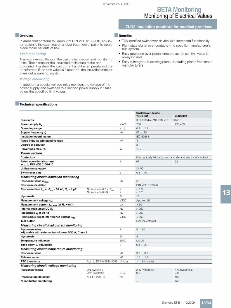
■ Overview
In areas that conform to Group 2 of DIN VDE 0100-710, any in-terruption to the examination and /or treatment of patients would place those patients at risk.
Limit monitoring
This is prevented through the use of changeover and monitoring units. These monitor the insulation resistance of the non-grounded IT system, the load current and the temperature of the transformer. If the limit value is exceeded, the insulation monitor gives out a warning signal.
Voltage monitoring
In addition, a special voltage relay monitors the voltage of the power supply and switches to a second power supply if it falls below the specified limit values.
■ Benefits
• TÜV-certified switchover device with increased functionality• Plant state signal over contacts – no specific manufacturer's
bus system• Easy operation over potentiometers as the set limit value is
always visible.• Easy to integrate in existing plants, including plants from other
manufacturers
■ Technical specifications
Switchover device7LQ3 361 7LQ3 362
Standards IEC 60364-7-710; DIN VDE 0100-710
Power supply Uv V AC 230 230/400
Operating range × Uv 0.9 … 1.1
Supply frequency fv Hz 50 … 60
Insulation coordination IEC 60664-1
Rated impulse withstand voltage kV 4
Degree of pollution 3
Power loss max. Pv W 10.7
Power sectionContactors Mechanically latched; mechanically and electrically locked
Rated operational current acc. to DIN VDE 0100-710
A 67 32
Utilization category -3 AC
Switchover time s 0.1 ... 10
Measuring circuit insulation monitoringResponse value Rresp kΩ 50
Response deviation DIN VDE 61557-8
Response time ton at Ron = 50 kΩ, Ce = 1 μF RF from ∞ to 0.5 × Ron s < 1.3RF from ∞ to 0 kΩ s < 0.7
Hysteresis % 15
Measurement voltage Um V DC Approx. 15
Measurement current Im max (at RF = 0 Ω) µA < 50
Internal resistance DC Ri kΩ > 250
Impedance Zi at 50 Hz kΩ > 250
Permissible direct interference voltage Ufg V DC < 300
Test button External/internal
Measuring circuit load current monitoringResponse value, adjustable with external transformer 50/5 A, Class 1
A 5 … 50
Hysteresis % 4
Temperature influence %/°C ≤ 0.05
Time delay tv, adjustable s 0.1 … 20
Measuring circuit temperature monitoringResponse value kΩ 3.2 … 3.8
Release value kΩ 1.5 … 1.8
PTC thermistor Acc. to DIN 44081/44082 Unit(s) 1 … 6 in series
Measuring circuit, voltage monitoringResponse values ON-switching 2 % hysteresis 4 % hysteresis
OFF-switching × Uc 0.9 0.9
Phase failure detection At L1, L2 or L3 ms -- 100
N-conductor monitoring -- Yes
ET_B1_2009-06_UEB_en.book Page 33 Montag, Dezember 7, 2009 1:05 PM
© Siemens AG 2009
BETA MonitoringMonitoring of Electrical Values
7LQ3 insulation monitors for medical premises
13/34 Siemens ET B1 · 10/2009
13
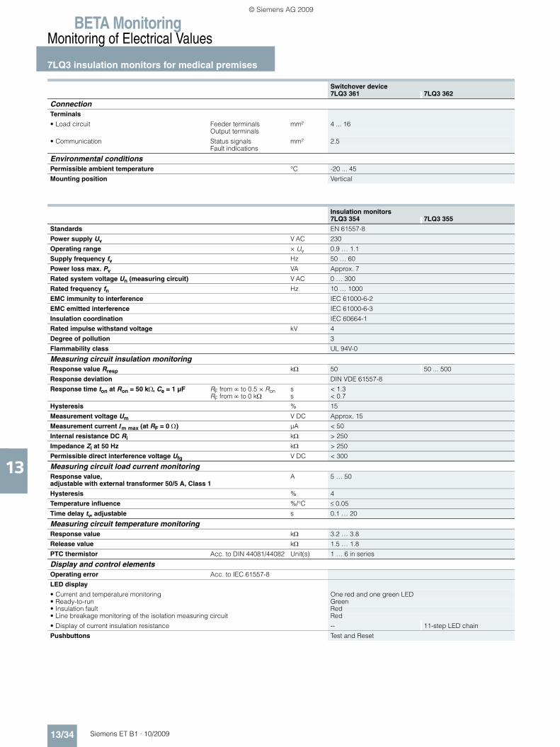
Switchover device7LQ3 361 7LQ3 362
ConnectionTerminals
• Load circuit Feeder terminals mm² 4 ... 16Output terminals
• Communication Status signals mm² 2.5Fault indications
Environmental conditionsPermissible ambient temperature °C -20 ... 45
Mounting position Vertical
Insulation monitors7LQ3 354 7LQ3 355
Standards EN 61557-8
Power supply Uv V AC 230
Operating range × Uv 0.9 … 1.1
Supply frequency fv Hz 50 … 60
Power loss max. Pv VA Approx. 7
Rated system voltage Un (measuring circuit) V AC 0 … 300
Rated frequency fn Hz 10 … 1000
EMC immunity to interference IEC 61000-6-2
EMC emitted interference IEC 61000-6-3
Insulation coordination IEC 60664-1
Rated impulse withstand voltage kV 4
Degree of pollution 3
Flammability class UL 94V-0
Measuring circuit insulation monitoringResponse value Rresp kΩ 50 50 ... 500
Response deviation DIN VDE 61557-8
Response time ton at Ron = 50 kΩ, Ce = 1 μF RF from ∞ to 0.5 × Ron s < 1.3RF from ∞ to 0 kΩ s < 0.7
Hysteresis % 15
Measurement voltage Um V DC Approx. 15
Measurement current Im max (at RF = 0 Ω) µA < 50
Internal resistance DC Ri kΩ > 250
Impedance Zi at 50 Hz kΩ > 250
Permissible direct interference voltage Ufg V DC < 300
Measuring circuit load current monitoringResponse value, adjustable with external transformer 50/5 A, Class 1
A 5 … 50
Hysteresis % 4
Temperature influence %/°C ≤ 0.05
Time delay tv, adjustable s 0.1 … 20
Measuring circuit temperature monitoringResponse value kΩ 3.2 … 3.8
Release value kΩ 1.5 … 1.8
PTC thermistor Acc. to DIN 44081/44082 Unit(s) 1 … 6 in series
Display and control elementsOperating error Acc. to IEC 61557-8
LED display
• Current and temperature monitoring One red and one green LED• Ready-to-run Green• Insulation fault Red• Line breakage monitoring of the isolation measuring circuit Red
• Display of current insulation resistance -- 11-step LED chain
Pushbuttons Test and Reset
ET_B1_2009-06_UEB_en.book Page 34 Montag, Dezember 7, 2009 1:05 PM
© Siemens AG 2009

BETA MonitoringMonitoring of Electrical Values
7LQ3 insulation monitors for medical premises
13/35Siemens ET B1 · 10/2009
13
Insulation monitors7LQ3 354 7LQ3 355
Output relayContacts for Overtemperature 2 CO contacts
Overload 2 CO contactsInsulation fault 2 CO contacts
Mode of operation Working current
Contacts AC 15 NO contacts A AC/V AC 3/230 AC 15 NC contacts A AC/V AC 1/230
Electrical service life AC 15, 1 A, 230 V AC Operating cycles
30 000
Thermal current A AC 5
ConnectionTerminals ± screw (Pozidriv) 2
• Conductor cross-sections Rigid mm2 2 × 2.5• Insulation fault Flexible, with end sleeve mm2 1 × 2.5
Environmental conditionsPermissible ambient temperature °C -20 … +60
Resistance to climate Acc. to EN 60068-1 20/060/04
Degree of protection Acc. to EN 60529 IP20, with connected conductors
Mounting position Any
Vibration stress Acc. to IEC 60068-2-6• Amplitude mm 0.35• Frequency Hz 10 … 55
Test and signaling panels 7LQ3 356 7LQ3 357
Standards DIN VDE 0100-710; IEC 60364-7-710
Rated voltage Un V AC/DC 24
Rated impulse withstand voltage Acc. to IEC 60664-1 kV 4
Voltage range AC 0.8 ... 1.1 x UnDC 0.9 ... 1.2 x Un
Rated current per input mA 0.25
Rated consumption VA 6
Rated operating mode Continuous operation
Degree of pollution Acc. to IEC 60664-1 2
Degree of protection• Enclosures Acc. to IEC/EN 60529 IP40• Terminals Acc. to IEC/EN 60529 IP20
Flammability class UL 94V-0
Vibration strain Acc. to IEC/EN 60068-2-6• Amplitude mm 0.35• Frequency Hz 10 … 55
Resistance to climate Acc. to IEC/EN 60068-1 20/045/04
Terminal marking EN 50005
Wire connection
• Solid mm2 1 × 1.5mm2 2 × 0.5
• Strand mm2 1 × 1mm2 2 × 0.2
• Strand with sleeve mm2 1 × 0.5
Conductor mounting Box terminals with wire protection
Device dimensions mm 80 × 160 × 57 82 × 150 × 57
Temperature range °C -20 ... +45
ET_B1_2009-06_UEB_en.book Page 35 Montag, Dezember 7, 2009 1:05 PM
© Siemens AG 2009

BETA MonitoringMonitoring of Electrical Values
7LQ3 insulation monitors for medical premises
13/36 Siemens ET B1 · 10/2009
13
Current transformer Class 17LQ3 358
Standards IEC/EN 60044-1, VDE 0414
Rated control voltage Uc V AC 230
Rated frequency Hz 50/60
Test voltage 50 Hz, 1 min kV 3
Rated transmission ratio kn A 50/5
Primary rated current A 50
Secondary rated current A 5
Rated power V/A 1.5
Class 1
Rated frequency Hz 50 ... 60
Highest voltage at equipment / insulation level kV 0.72/3
Overcurrent factor FS5• Thermal rated short-time current × In 60• Thermal rated continuous current × In 1.2
Expanded current range % 120
Permissible ambient temperature °C -20 … +60
Test and signaling combination for insulation monitors7LQ3 360
Standards DIN VDE 0100-710; IEC 60364-7-710
Rated voltage Un V AC 24
Voltage range AC 0.8 ... 1.1 × Un
Connected load W 0.5
Rated operating mode Continuous operation
EMC• Static discharge Acc. to IEC/EN 61000-4-2 kV 8 (air discharge)• RF irradiation Acc. to IEC/EN 61000-4-3 V/m 10• Rapid transients Acc. to IEC/EN 61000-4-4 kV 2• Surge voltage (surge) Acc. to IEC/EN 61000-4-5 kV 1
Degree of protection IP30
Amplitude mm 0.35
Frequency Hz 10 ... 55
Temperature range °C -5 ... +55
Resistance to climate Acc. to IEC/EN 60068-1 05/055/04
Terminal marking EN 50005
Wire connection• Solid mm2 1 × 4• Strand with sleeve and plastic collar mm2 1 × 2.5• Strand with sleeve and plastic collar DIN 46228-1/-2/-3/-4 mm2 2 × 1.5• Strand with sleeve DIN 46228-1/-2/-3 mm2 2 × 2.5
Conductor mounting Box terminals with wire protection
Device dimensions mm 80 × 80 × 35
ET_B1_2009-06_UEB_en.book Page 36 Montag, Dezember 7, 2009 1:05 PM
© Siemens AG 2009

BETA MonitoringMonitoring of Electrical Values
7LQ3 insulation monitors for medical premises
13/37Siemens ET B1 · 10/2009
131) Tripping units must be ordered separately.
Voltage relays
5TT3 411 5TT3 412
Rated control voltage Uc V AC 230 230/400
Overload capability × Uc 1.15 1.1
Rated frequency Hz 50/60
Response values ON-switchingOFF-switching × Uc
2 % hysteresis0.9
4 % hysteresis0.9
Minimum contact load V/mA 10/100
Phase failure detection At L1, L2 or L3 ms -- 100
N-conductor monitoring -- Yes
Rated insulation voltage Ui Between coil/contact kV 4
Contacts AC 15 NO contactsAC 15 NC contacts
32
31
Electrical service life in switching cycles AC 15, 1 A, 230 V AC 5 × 10⁵
Rated impulse withstand voltage Acc. to IEC 60664-1 kV 4
Degree of pollution 2
Terminals ± screw (Pozidriv) 2
Conductor cross-sections• Rigid• Flexible, with end sleeve
mm2
mm22 × 2.52 × 1.5
Permissible ambient temperature °C -20 … +60
Resistance to climate Acc. to EN 60068-1 20/060/04
IT line transformer4AT3/4AT4
In the case of isolating transformers used to set up medical IT systems, overcurrent protective devices are only permissible as protection against short-circuits. To protect the isolating transformers against overload they are fitted with monitoring devices that signal an excessive rise in tempera-ture (e. g. 7LQ3 354 insulation monitors).
Standards EN 61558-2-15
Safety class I
Static shield between primary and secondary winding With insulated connection
Thermistor transformer protection Warning in the event of thermal overload1)
Insulation monitoring With center tap
Short-circuit voltage uz % ≤ 3
No-load supply current i0 % ≤ 3• Starting current (rush), max. x I1N
Rated ambient temperature ta /Thermal Class 55 °C/H
ET_B1_2009-06_UEB_en.book Page 37 Montag, Dezember 7, 2009 1:05 PM
© Siemens AG 2009

BETA MonitoringMonitoring of Electrical Values
7LQ3 insulation monitors for medical premises
13/38 Siemens ET B1 · 10/2009* You can order this quantity or a multiple thereof.
13
■ Selection and ordering data
Version Ue Ie Uc MW DT Order No. Priceper PU
PU PS*/P. unit
PG Weightper PU
approx.
V AC A V AC Unit(s) Unit(s) kg
Switchover devices according to VDE 0100 710 for medical premises N2-pole, for medical premises of Group 2, for switching over two redundant supply leads, monitoring of IT system and the IT line transformer, up to 8 kVA switchover time
230 80 (36) 230 D 7LQ3 361 1 1 027 17.500
4-pole, for use with symmetric loads
230 80 (36) 230/400 D 7LQ3 362 1 1 027 17.500
Insulation monitors
With load current and temperature monitoring for medi-cal premises
300 6 B 7LQ3 354 1 1 027 0.420
With load current and temperature monitoring of medical premises with adjustable response value of 50 … 500 kΩ and output for 7LQ3 360 test and signaling combination
300 8 } 7LQ3 355 1 1 027 0.590
Test and signaling panels
For switchover devices, 24 V AC/DC 50/60 Hz
Surface mounting B 7LQ3 356 1 1 027 0.200
Flush mounting B 7LQ3 357 1 1 027 0.200
ET_B1_2009-06_UEB_en.book Page 38 Montag, Dezember 7, 2009 1:05 PM
© Siemens AG 2009

BETA MonitoringMonitoring of Electrical Values
7LQ3 insulation monitors for medical premises
13/39Siemens ET B1 · 10/2009* You can order this quantity or a multiple thereof.
13
■ Accessories
IT line transformer Features• Acc. to EN 61558-2-15• Safety class I • With static shield between primary and secondary winding
with insulated connection • With thermistor transformer protection for warning of thermal
overload1)
• With central tap for insulation monitoring• Short-circuit voltage uz ≤ 3 %,• No-load supply current i0 ≤ 3 %• Starting current max. 8 × I1N• ta = 55 °C/H
1) Delivery time depends on the number of items ordered, the specified deliv-ery time applies to an order quantity of up to 5 items.
Version Ue Ie Uc MW DT Order No. Priceper PU
PU PS*/P. unit
PG Weightper PU
approx.
V AC A V AC Unit(s) Unit(s) kg
Test and signaling combinations for insulation monitors
24 V AC, 50/60 Hz B 7LQ3 360 1 1 027 0.100
Current transformers 50A/5A AC Class 1
With base angle
230 } 7LQ3 358 1 1 027 0.390
Voltage relays for the overvoltage monitoring of medical premises
Single-phase against N with test button, switching thresholds: 0.9 × Un, 2 % hysteresis
2 NO, 2 NC 230 4 230 4 C 5TT3 411 1 1 027 0.220
Single, two or three-phase against N, with asymmetry, reverse voltage and phase failure detection, with N-conductor monitoring, and one test button each for the phases, switching thresholds: 0.9 × Un, 4 % hysteresis
1 CO, 1 NO, 1 NC 230 4 230/400 4 C 5TT3 412 1 1 027 0.230
Rated power Pn
Voltage rise during no-load operation uA
Rated voltages Secondary-side short-circuit protection for the transformer with motor starter protector
DT1) Order No. PU PS*/P. unit
PG Cuweightper PU
approx.
Weightper PU
approx.
Input U1N Output U2N Type Set value
kVA % V V A Unit(s) Unit(s) kg kg
IT transformers
• Degree of protection IP00
2.5 3.6 230 230-115 3RV10 21-4CA10 21 C 4AT30 12-1TA71-3MA0 1 1 104 7.400 25.5003.15 3.6 230 230-115 3RV10 31-4EA10 26 C 4AT36 02-1TA71-3MA0 1 1 104 6.800 33.0004 3.6 230 230-115 3RV10 31-4EA10 29 C 4AT36 12-1TA71-3MA0 1 1 104 9.400 36.000
5 3.6 230 230-115 3RV10 31-4FA10 36 C 4AT39 02-1TA71-3MA0 1 1 104 9.700 45.0006.3 3.6 230 230-115 3RV10 31-4GA10 40 C 4AT39 12-1TA71-3MA0 1 1 104 13.800 49.0008 3.7 230 230-115 3RV10 41-4JA10 49 C 4AT43 02-1TA71-3MA0 1 1 104 12.600 63.00010 2.5 230 230-115 3RV10 41-4KA10 61 C 4AT43 12-1TA71-3MA0 1 1 104 19.600 70.000
• Degree of protection IP23
2.5 3.6 230 230-115 3RV10 21-4CA10 21 C 4AT30 12-1TA71-3MC0 1 1 104 7.400 33.5003.15 3.6 230 230-115 3RV10 31-4EA10 26 C 4AT36 02-1TA71-3MC0 1 1 104 6.800 41.0004 3.7 230 230-115 3RV10 31-4EA10 29 D 4AT36 12-1TA71-3MC0 1 1 104 9.400 44.000
5 3.6 230 230-115 3RV10 31-4FA10 36 C 4AT39 02-1TA71-3MC0 1 1 104 9.700 59.0006.3 3.9 230 230-115 3RV10 31-4GA10 40 C 4AT39 12-1TA71-3MC0 1 1 104 13.800 63.0008 3.7 230 230-115 3RV10 41-4JA10 49 C 4AT43 02-1TA71-3MC0 1 1 104 12.400 77.00010 2.5 230 230-115 3RV10 41-4KA10 61 C 4AT43 12-1TA71-3MC0 1 1 104 19.600 84.000
ET_B1_2009-06_UEB_en.book Page 39 Montag, Dezember 7, 2009 1:05 PM
© Siemens AG 2009

BETA MonitoringMonitoring of Electrical Values
7LQ3 insulation monitors for medical premises
13/40 Siemens ET B1 · 10/2009
13
■ Characteristic curves
7LQ3 354 and 7LQ3 355 insulation monitors
The following diagrams show the function of the measuring circuits of the temperature monitors (top left), the load current monitors (bottom left) and the insulation monitors (right).
t
t
I2_13579
11-1421-2411-1221-22
VU
R
P1/P2
≥ 3,2 kΩ
≤ 1,8 kΩ
Over-temperature/sensor break
Power failure
I2_13580a
VU
>Hysterese
N
31/4134/44
32/42
t
ttv
> onoff
LEDred
onoff
LEDgreen
I2_13581
VU
FR
51-5461-6451-5261-62
51-5461-6451-5261-62
anR
t
t
BreakMeasuring circuit
With
out f
ault
stor
age
(jum
per L
T1-L
T2)
With
faul
t sto
rage
(w
ithou
t jum
per L
T1-L
T2)
LED “MK“OnOff
LED “AL“
Reset push-button LT
OnOff
LED “MK“OnOff
LED “AL“OnOff
Ground fault
ET_B1_2009-06_UEB_en.book Page 40 Montag, Dezember 7, 2009 1:05 PM
© Siemens AG 2009

BETA MonitoringMonitoring of Electrical Values
7LQ3 insulation monitors for medical premises
13/41Siemens ET B1 · 10/2009
13
Test and signaling panels Test and signaling combination for insulation monitors
Voltage relays
The voltage relay switches at a phase asymmetry of approx. 6 to 8 %, regardless of the response values for undervoltage. The above diagram also show the timing interval.
7LQ3 356, 7LQ3 357
X1-L1
X2-L1
X3-L2
X4-L2
X5-
LED 1
LED 2
LED 3
LED 4
LED 5
LED 6
LED 7
LED 8
X11-
X8-
X6-
X7-
I2_1
3989
>
> I
Line 1 OK
Line 1 failure
Line 2 OK
Line 2 failure
Test /
lationIso-
Over-temperature
Overload
Output
HornAcknowledgementlamp test
Dark Bright
SM
7LQ3 360
X1/X2
ON
ER
anR
t
t
UH
U
Ground fault
Horn
GreenLED
Yellow LED
Acknow-ledgement pushbutton
I2_1
3990
I2_1
3990
5TT3 411
t
U
L
L
b
aUN
.3 - .4
.1 - .2I2_13574
Response value
Hysteresis
5TT3 412
t
U L3L2L1
UN
UU
11 - 14
11 - 12I2_13576a
t
onoffU
N
ET_B1_2009-06_UEB_en.book Page 41 Montag, Dezember 7, 2009 1:05 PM
© Siemens AG 2009

BETA MonitoringMonitoring of Electrical Values
7LQ3 insulation monitors for medical premises
13/42 Siemens ET B1 · 10/2009
13
■ Dimensional drawings
Switchover devices
The 7LQ3 361 and 7LQ3 362 switchover devices are designed for installation in DIN floor-mounted distribution boards of the ALPHA 630 range and ALPHA AS modular distribution boards with a cabinet depth of at least 320 mm. More information about ALPHA distribution boards can be found in Catalog ET A1 (Order No.: E86060-K8210-A101-B2-7600). Contact your local Siemens representative for information on additional versions.
7LQ3 361
I2_17066250 132
171
212
-X1 -X2
-X3
K1
K3 K4
K5
K20 S1
K6 K7
K9
K8
K10
T01
F1 F2 F3 K13
K2
7622
537
647
058
572
884
0 900
ET_B1_2009-06_UEB_en.book Page 42 Montag, Dezember 7, 2009 1:05 PM
© Siemens AG 2009

BETA MonitoringMonitoring of Electrical Values
7LQ3 insulation monitors for medical premises
13/43Siemens ET B1 · 10/2009
13
The 7LQ3 361 and 7LQ3 362 switchover devices are designed for installation in DIN floor-mounted distribution boards of the ALPHA 630 range and ALPHA AS modular distribution boards with a cabinet depth of at least 320 mm. More information about ALPHA distribution boards can be found in Catalog ET A1 (Order No.: E86060-K8210-A101-B2-7600). Contact your local Siemens representative for information on additional versions.
Insulation monitors
7LQ3 362
250 132
171
212
-X1 -X2
-X3
K1
K3 K4
K5
K20 S1
K6 K7
K9
K8
K10
T01
F1 F2 F3 K13
K2
76
I2_17067
225
376
470
585
728
840 90
0
7LQ3 354 7LQ3 355
14055
43
45 90
I2_1
3807
P2P1 i k PE‘
L‘
PE
L
PT LT1 LT2A1
2124 3134 4144 54 51 64 61 X2 X514
22 32 42 52 62 X112
11
A2
A1 P1 P2 i k PE PT LT1 LT2
14 2411 21 34 31 44 41 54 51 64 61
PE‘ LL‘A2
52 6232 4212 22
105
ET_B1_2009-06_UEB_en.book Page 43 Montag, Dezember 7, 2009 1:05 PM
© Siemens AG 2009

BETA MonitoringMonitoring of Electrical Values
7LQ3 insulation monitors for medical premises
13/44 Siemens ET B1 · 10/2009
13
Test and signaling panels
Current transformer Test and signaling combination for insulation monitors
Voltage relays
7LQ3 356
80 5716
0
I2_1
3985
7LQ3 357
150
82 4710
I2_1
3986
7LQ3 358
1078
4627
6,5
60
40
20 30
I2_1
3810
7LQ3 360
I2_1
4002
80
80
55
5535
6
ON
TEST
5TT3 411 5TT3 412
L3L2L1 N
241114
23 31
3212
N La
Lb
Y1 Y2 11 12
41 42
23 24
33 34
727255
43
45 90
I2_1
3712
ET_B1_2009-06_UEB_en.book Page 44 Montag, Dezember 7, 2009 1:05 PM
© Siemens AG 2009

BETA MonitoringMonitoring of Electrical Values
7LQ3 insulation monitors for medical premises
13/45Siemens ET B1 · 10/2009
13
■ Schematics
Switchover devices
7LQ3 361
7LQ3 362
Terminal diagram for connection of 7LQ3 361 and 7LQ3 362 switchover devices to test signaling device (e. g. 7LQ3 356 and 7LQ3 357 test and signaling panels)
I2_1
7068
X1:7
L1 N L1 N
X1:8L1
230 115 115 2N SCH P1 P20
NX2:1 X2:2L1
X2:4 X2:10 X2:11X2:SN (MZ)L2
X1:PE X1:4 X1:5X1:1 X1:2L1 L2
X2:5 X2:3X1:PE
Line 1
To IT transformer From IT transformer
IT system loadLine 2
I2_1
7069
400 400 400 230 230 230 2N SCH P1 P2
X1:9
L1 L2 L3 N
X1:10L1 L2
X1:11L3
X1:12N
X2:1 X2:4L1
X2:7 X2:10 X2:12 X2:13X2:SN(STP)L2 L3
X1:3 X1:4 X1:PEX1:1 X1:2L1 L2 L3 N
X1:7 X1:8 X1:PEX1:5 X1:6L1 L2
X2:2 X2:6L3
X2:8
Line 1
To IT transformer From IT transformer
IT system loadLine 2
I2_1
7070X3:1 X3:2 X3:4 X3:5 X3:6 X3:7 X3:8 X3:9 X3:10 X3:11 X3:12 X3:13 X3:14 X3:15
Test buttonISO
Line 1Operation
Line 1Failure
Line 2Operation
Line 2Failure
Temperaturemonitoring
Currentmonitoring
ISOmonitoring
IT transformer
ET_B1_2009-06_UEB_en.book Page 45 Montag, Dezember 7, 2009 1:05 PM
© Siemens AG 2009

BETA MonitoringMonitoring of Electrical Values
7LQ3 insulation monitors for medical premises
13/46 Siemens ET B1 · 10/2009
13
Insulation monitors
Test and signaling panels Test and signaling combination for insulation monitors
Voltage relays
Use La and Lb for monitoring 2 phases or 2-channel monitoring of 1 phase. If only La is used, Lb must be bridged with La.
Terminal diagram for connection of 7LQ3 361 and 7LQ3 362 switchover devices to the central building control system devices
7LQ3 354
7LQ3 355
I2_1
7071
X3:18
X3:16 X3:17
X3:19 X3:20 X3:21 X3:22 X3:23 X3:24 X3:25 X3:26 X3:27 X3:28 X3:29 X3:30
MCBtripped
Line 1Operation
Line 2Operation
Line 1Failure
Line 2Failure
Temperaturemonitoring
Currentmonitoring
ISObad
ISOgood
ContactorLine 1 not
switched off
ContactorLine 2 not
switched off
IT transformer IT system
I2_1
3713
a
11 14 12 21 24 22 31 34 32 41 44 42 51 54 52 61 64 62
LT1
LT2
iP2P1 PE'A2A1 PE PTLL'k
7LQ3 354Transformer protection Insulation monitors
I2_1
3811
a
11 14 12 21 24 22 31 34 32 41 44 42 51 54 52 61 64 62 X1 X2 X5
7LQ3 355 LT1
LT2
iP2P1 PE'A2A1 PE PTLL'k
Transformer protection Insulation monitors
7LQ3 356, 7LQ3 357
1 2 3 4 5 6 7 8
X5 X4 X3 X2 X1A1 A2 SM PT2 PT1 X8 X7 X6
PT
QH/LT
+
I2_13987
7LQ3 360
I2_13988
PT1PT2X1X2X5
Test
Receipt
ON
Ground fault
5TT3 411 5TT3 412
I2_1
3714
a
N
Lb Y1 Y2La
11
12
23
24
33
34
41
42
I2_1
3715
a
L1L2
N
L3112331
14 122432
ET_B1_2009-06_UEB_en.book Page 46 Montag, Dezember 7, 2009 1:05 PM
© Siemens AG 2009

BETA MonitoringMonitoring of Electrical Values
7LQ3 insulation monitors for medical premises
13/47Siemens ET B1 · 10/2009
13
■ More information
Connection examples
Insulation monitor
Insulation monitor
7LQ3 354
I2_1
7057
11 14 12 21 24 22 31 34 32 41 44 42 51 54 52 61 64 62
P1 P2 i k L PE PTA1 A2
PE PEN L2
L L1
> >
L ' PE '
1)
7LQ3 354
7LQ3 358
7LQ3 360
X1 X2 X5 PT1 PT2
1) If there is no center tap, L/L' is connected to L1 or L2.
2) The 24 V AC power supply unit (e.g. 4AC3 616) needs to be powered over the IT system.
Isolating transformer3.15 ... 8 kVA
Current transformer
Transformer protection
Overtemperature Overcurrent
Insulation monitor
230 V AC
24 V AC4AC3 616
Test andsignaling combination
2)
7LQ3 355
Connection of up to four 7LQ3 360, 7XV9 306, 7XV9 304 or 7XV9 302 test and signaling combinations; compare with connection example on page 13/49 and compare contact assignment between previous and current test and signaling combinations on page 13/50.
3,15 … 8 kVA
11 21 31 41 51 6114 24 34 44 54 6412 22 32 42 52 62
P1
LT1
LT2
P2 i k L PE PTA1 A2
PE PEN L2
230 V AC
L1)
L1
7LQ3 355
> >
L' PE'
7LQ3 360
X1 X2 X5
X1 X2 X5 PT1 PT2
PE PT
IOvertemperature Overcurrent
Transformer protection
Current transfor.
ResetExternal
External test
Insulation monitor
R <F ALR /Measuring circuit
breakinsulation fault
Jumpers =non-latching
Isolating transformer
1) If there is no center tap, L/L' is connected to L1 or L2.Test and
signaling combination
7LQ3 358
I2_1
3994
ET_B1_2009-06_UEB_en.book Page 47 Montag, Dezember 7, 2009 1:05 PM
© Siemens AG 2009

BETA MonitoringMonitoring of Electrical Values
7LQ3 insulation monitors for medical premises
13/48 Siemens ET B1 · 10/2009
13
Test and signaling panels
X1 ... X7 Fault signaling inputs
X8 Acknowledgement of horn/lamp test
SM Central indication output
PT1, PT2 Test button for insulation monitors
7LQ3 356, 7LQ3 357
X1
PT1PT2
PT PE
X2 X3 X4 X5 X6 X7 X8 SM A1
A2
L(L+)
N(L-)
1 2 3 4 65 7 8
I2_1
3991
7LQ3 354 / 7LQ3 355
7LQ3 356 /7LQ3 357
11 14 31 34 51 54
OK
Failu
re
OK
Failu
re
Line 2Line 1
ExternalQH / LT
ET_B1_2009-06_UEB_en.book Page 48 Montag, Dezember 7, 2009 1:05 PM
© Siemens AG 2009

BETA MonitoringMonitoring of Electrical Values
7LQ3 insulation monitors for medical premises
13/49Siemens ET B1 · 10/2009
13
Connection example: 7LQ3 355 insulation monitor with 7XV9 306 test and signaling combination
Connection of up to four test and signaling combinations (e. g. 7LQ3 360 test and signaling combination and the now discontin-ued 7XV9 306, 7XV9 304 or 7XV9 302 test and signaling combinations.
The test and signaling combinations require an external transformer 24 V AC (e. g. 4AC3 616) for the power supply.
7LQ3 355
11 14 12 21 24 22 31 34 32 41 44 42 51 54 52 61 64 62
PT 52 51 PE
X1 X2 X5
P1
LT1
LT2
P2 i k L PE PTA1 A2
PE PEN L2
L L1
L ' PE '
1)
7LQ3 355
4
5
2
3
6
7XV9 30618
A2A1 15
4
5
2
3
6
7XV9 306
4
5
2
3
6
7XV9 306
4
5
2
3
6
7XV9 306
7LQ3 358
5TT3 185
B1
2)AC 24 V4AC3 616
1) If there is no center tap, L/L' is connected to L1 or L2.2) The 24 V AC power supply unit (e.g. 4AC3 616) needs to be powered over the IT system.
230 V AC
> >
Isolating transformer3.15 ... 8 kVA
Current transformer
Transformer protection
Overtemperature OvercurrentR <F Ron
/ measuring circuit interruptionInsulation fault
Insulation monitor
External test
ResetExternal
Jumper =non-latching
I2_13812c
ET_B1_2009-06_UEB_en.book Page 49 Montag, Dezember 7, 2009 1:05 PM
© Siemens AG 2009

BETA MonitoringMonitoring of Electrical Values
7LQ3 insulation monitors for medical premises
13/50 Siemens ET B1 · 10/2009
13
Compare the contact assignment of the now discontinued 7XV9 306, 7XV9 304 and 7XV9 302 test and signaling combinations with the contact as-signment of the current 7LQ3 360 test and signaling combination.
Monitoring of medical premises
Medical premises are all rooms used for the examination or treat-ment of persons or animals. In addition to doctors' surgeries and clinics, this includes treatment rooms for hydrotherapy and physiotherapy and massage rooms.
TÜV approved and safety-tested changeover and monitoring units ensure the reliable power supply of such premises. Any in-sulation monitors and voltage relays installed in these changeover and monitoring units must meet the requirements of DIN VDE 0100-710 and IEC 60364-7-710.
The standard DIN VDE 0100-710, published in 2002, divides medical premises into three groups.
For premises in groups 0 and 1, the standard requirements in-clude implementation of the system type TN-S and residual cur-rent protective devices (RCD) for protection against excessively high touch voltages.
The premises of group 2 are defined as follows:• The system must not be disconnected in the event of a first
short circuit to frame or to ground or if the general power supply fails.
• Repetition of treatment is unacceptable for patients or it is im-possible to obtain results of examinations again.
• An irregularity (a fault) in the power supply can cause danger to life.
• A piece of equipment used for medical purposes, which is used occasionally for applications in accordance with DIN VDE 0100-710.2.7, should be assigned to group 2.
Typical locations in group 2 are areas used for anesthesia, oper-ating and recovery in hospitals, clinics or doctors' surgeries, as well as for equipment used in veterinary medicine.
Standard DIN VDE 0100-710 makes the following stipulations:• Constant monitoring of the supply voltage on the preferred
supply line and on the second supply line.• Automatic changeover to the second supply line within a de-
fined time (< 0.5 s or < 15 s)• Reliable operation even if a fault occurs
(one-fault security).
The switchover device monitors the supply voltage on the pre-ferred and second supply line for undervoltage and power fail-ure. As soon as a voltage drop to a defined value is determined, the voltage relays operate and the switchover device automati-cally switches to the second supply line. As soon as the power is restored on the preferred supply line, the system switches back to it.
IT system
In the IT system designation, the first letter describes the grounding conditions of the power source. I stands for insulation of all live parts from the ground or the linking of a point to the ground over an impedance. The second letter designates the grounding conditions of the body of the electrical plant.
T means that the body is directly grounded, independently of any existing grounding of a point of the power source.
Medical IT systems
Standard DIN VDE 0100-710 makes the following stipulations for a medical IT system in group 2:• The medical IT system must be used for socket outlet current
circuits in the patient environment. This also applies for cir-cuits supplying operating room lights.
• At least one IT system is required for each room group.• Separate circuits must be provided for multiple socket outlets.• First faults must not lead to disconnection of the system.
The IT system is powered over an isolating transformer or an in-dependent power source (e. g. a battery). The special feature here is the fact that no active conductor is directly linked to the ground in this system. This has the advantage that only a small residual current can flow in the event of a insulation fault. This is essentially dictated by the leakage capacities and is harmless to patients and staff. The upstream fuse does not respond so that the power supply, and therefore operation, is maintained, even in the event of a phase-to-ground fault. The high reliability of IT systems is ensured by continuous insulation monitoring. The in-sulation monitor detects isolation faults as they develop and promptly signals if a value drops below the limit value before any further insulation faults can cause an unforeseen interruption. The temperature of the transformer and the transformer load continue to be monitored constantly. Any exceeding of limit val-ues is signaled immediately.
31
32
33
34
35
7XV9 3027XV9 3047XV9 306
1
23
3
4
5
2
4
5
6
X5
PT1
PT2
X2
X1
7LQ3 360
Test
24 V AC
Fault input
I2_1
3813
b
I2_12110
L2
L3
L1
Body
IT system
PE
ET_B1_2009-06_UEB_en.book Page 50 Montag, Dezember 7, 2009 1:05 PM
© Siemens AG 2009

BETA MonitoringMonitoring of Electrical Values
7LQ3 insulation monitors for medical premises
13/51Siemens ET B1 · 10/2009
13
Insulation monitoring
The 7LQ3 354 and 7LQ3 355 insulation monitors are used for the monitoring of the insulation resistances of non-grounded IT sys-tems in medical premises. They also simultaneously monitor the load current and the temperature of the IT isolating transformer. The devices can monitor both three-phase and AC systems.
Temperature measurement: The temperature in the transformer development is recorded over PTC thermistor or NC contacts.
As well as an adjustable response value of 50 … 500 kΩ, the 7LQ3 355 insulation monitor also has an 11-step LED chain for displaying the current insulation resistance of the system. A range of different colored LEDs indicate the insulation resis-tance within the range of 20 kΩ … 1 MΩ. This allows insulation deteriorations to be detected even before an alarm is triggered. The device is also equipped with an additional relay for connec-tion of a test and signaling combination. This means that the 7LQ3 360 test and signaling combination and the previously un-available test and signaling combinations 7XV9 306, 7XV9 304 and 7XV9 302 can be connected to the 7LQ3 355 insulation monitors (see the diagram on page 13/50 "Connection example: 7LQ3 355 insulation monitor to 7XV9 306 test and signaling combination").
Load current sensing: The 7LQ3 358 current transformer detects the load current of a phase. Evaluation is carried out over the 7LQ3 354 and 7LQ3 355 insulation monitors.
Evaluation: If one of the values is outside the limit values, an alarm is triggered. The LED for the relevant fault lights up and the alarm relay switches. The information is made available over the changeover contacts and can be displayed on the 7LQ3 356 and 7LQ3 357 test and signaling panels.
Voltage monitoring
In the case of undervoltage, there is no guarantee that medical equipment will continue to function. Because of the risk this pre-sents to patients, e. g. during operations, the changeover unit must reliably switch to a second power supply in the event of an undervoltage in the preferred power supply.
The voltage relays switch when the voltage falls below 90 % of the rated voltage. The 5TT3 411 relays serve to monitor a single-phase infeed. Three-phase infeeds can be monitored using 5TT3 412 relays. These relays also offer asymmetry, reverse volt-age and phase failure detection.
TÜV-certified switchover device
The 7LQ3 361 and 7LQ3 362 switchover devices are tested and certified by TÜV Rhineland. Switchover devices comply with DIN VDE 0100-710:2002-11 and IEC 60364-7-710:2002-11.
Rhineland TÜV certificate for 7LQ3 361 and 7LQ3 362 switchover devices
ET_B1_2009-06_UEB_en.book Page 51 Montag, Dezember 7, 2009 1:05 PM
© Siemens AG 2009

BETA MonitoringMonitoring of Electrical Values
7LQ3 insulation monitors for medical premises
13/52 Siemens ET B1 · 10/2009
13
Components and control elements in 7LQ3 361 and 7LQ3 362 switchover devices
Control elements for insulation monitors
1
I2_1
7073
4
5
87
3
2
6
Meaning
1 Terminal block X1
2 Terminal block X2
3 Terminal block X3
4 Mechanical latching
5 Miniature circuit breakers
6 Voltage relay test pushbuttons
7 Insulation monitors
8 Temperature monitoring test pushbuttons
7LQ3 354
7LQ3 355
A1 P1 P2 i k PE PT LT1 LT2
14 2411 21 34 31 44 41 54 51 64 61
PE‘ LL‘A2
52 6232 4212 22
1
67
10
1189
2 3 4 5
I2_1
3716
P2P1 i k PE‘
L‘
PE
L
PT LT1 LT2A1
2124 3134 4144 54 51 64 61 X2 X514
22 32 42 52 62 X112
11
A2
I2_1
3814
1 2 5a
789
6
119a
10
3 4 5
LED Meaning
1 Current monitoring (green)
Lights up if the current is correct (Go-state)
2 Current monitoring">I" (red)
Lights up in the case of overcurrent
3 Insulation monitoring "ON" (green)
Lights up when the power supply is switched on (ready to run)
4 Insulation monitoring "MK" (red)
Lights up if a line of the measuring circuit is interrupted (L, L’, PE, PE’)
5 Insulation monitoring "AL" (red)
Lights up in the case of an insulation fault, RF<Ron (value has fallen below the response value)
5a Line insulation monitoring "RF" (location, yellow, green)
11-step LED chain to display the current resistance
6 Temperature monitoring (green)
Lights up when the power supply is switched on
7 Temperature monitoring (red)
Lights up in the event of overtemperature or an interruption in the sensor circuit
Pushbutton/rotary regulator
Meaning
8 Rotary regulator response value ">I"
Setting of the response value for current monitoring
9 Rotary regulator delay time
Setting of delay time after which the CO contacts return to their normal position if the current value exceeds the set response value.
9a Rotary regulator response value "Ran kΩ"
Setting of the response value for line insu-lation monitoring.
10 "Test" pushbuttons Pressing the test button simulates an insulation deterioration in the measuring circuit (RF approx. 40 kΩ) and checks that the line insulation monitor is fully functional.
11 "Reset" pushbuttons Deletion of fault if the fault storage is activated
ET_B1_2009-06_UEB_en.book Page 52 Montag, Dezember 7, 2009 1:05 PM
© Siemens AG 2009

BETA MonitoringMonitoring of Electrical Values
7LQ3 insulation monitors for medical premises
13/53Siemens ET B1 · 10/2009
13
Control elements of the test and signaling panels
Note: Customized reporting and signaling panels can be produced, for instance with an integrated intercom, for the changeover and monitoring units. For more information on this contact your local Siemens representative.
Control elements of the test and signaling combination
Control elements of voltage relay
7LQ3 356, 7LQ3 357
I2_1
3995
>I
7LQ3 357
line 1on
line 1failure
insulationok
test
line 2failure
line 2on
LED window displays Meaning
Line 1 On Power supply is implemented over the preferred infeed
Line 2 On + Line 1 Failure
Power supply is implemented over the second line as the preferred infeed has failed
Line 1 On + Line 2 Failure
Power supply is implemented over the preferred infeed. However the second line is no longer available
Line 2 On + Line 1 Failure+ Line 2 Failure
Power supply is implemented over the second line as the preferred infeed is faulty. There is undervoltage on the sec-ond line
Overload Excessive power consumption of the IT system
Overtemperature The transformer of the IT system isoverloaded
Insulation is good The transformer of the IT system is overloaded
Insulation is defective The insulation resistance of the IT system is too low
Test Pushbutton for testing the insulation moni-toring devices
Acknowledgement push-button/lamp test
Pushbutton for acknowledging the acous-tic alarm signal/function test of the dis-play elements
7LQ3 360
I2_1
3996
ON
TEST
LED/pushbutton Meaning
ON Green LED The LED lights up if the power supply is applied
Ground fault
Yellow LED Insulation fault: the insulation resistance of the IT system is too low
Test Pushbutton for testing the insulation moni-toring devices
Acknowledgement pushbutton
Pushbutton for acknowledging the acous-tic alarm signal
5TT3 411 5TT3 412
N La
Lb
Y1 Y2 11 12
41 42
23 24
33 34
1
2
I2_1
3717
L3L2L1 N
241114
23 31
3212
2
2
21
I2_1
3720
LED/pushbutton Meaning
1 5TT3 411: Yellow LED 5TT3 412: Green LED
The LED lights up if the system isfault-free
2 Test button Pressing the test button simulates an undervoltage. The three-phase 5TT3 412 voltage relay has a test button for each phase.
ET_B1_2009-06_UEB_en.book Page 53 Montag, Dezember 7, 2009 1:05 PM
© Siemens AG 2009

BETA MonitoringMonitoring of Electrical Values
Notes
13/54 Siemens ET B1 · 10/2009
13
ET_B1_2009-06_UEB_en.book Page 54 Montag, Dezember 7, 2009 1:05 PM
© Siemens AG 2009