Embed Size (px)
Citation preview

— C ATALOG
ABB Ability™ System 800xA 6.0.3.2Product Catalog

— Table of contents
008 System 800xA Extended Automation
010 System 800xA, System Capabilities
012 System 800xA Software
012 License
013 800xA 6.0 System, Lifecycle Management – System Expansion
013 Automation Sentinel Program
014 System 800xA 6.0 System Identifier
014 Control System Lifecycle Management Program
014 System Identifier
015 – 036 800xA 6.0 System
015 System 800xA Base System
016 Tag Expansion
017 Subscriber System Tags
018 System 800xA Applications
018 Connectivity
019 Connectivity
020 System Extensions
—01—01
—02
—03
—01—01
—01
—02
—01
—01
2

021 Cyber Security
022 Control Room Solutions
023 Control Room Prestudy
024 Operator Workplaces
025 Extended Operations
025 Live Video System - Public Addressing
026 Batch Management
027 Standard Engineering Tools
027 Engineering Systems
028 Professional Engineering Tools
028 Information Management
029 System 800xA History
030 IM Historian Server
031 IM Historian
032 Safety
032 Asset Optimization
033 Asset Monitors
033 Device Management & Fieldbuses
035 Libraries
036 Localization
037 – 057 AC 800M Processor Units
038 AC 800M Controllers selection guide
042 Hardware Upgrade orders
042 System Units
042 AC 800M Processor Units
—03
3

046 AC 800M High Integrity Units
047 Extra Batteries
047 Control Network
047 Serial Interfaces on TP830
048 Communication Interface selection guide
050 Serial Communication Interface
050 MODBUS TCP
050 PROFIBUS DP
050 PROFINET IO
051 FOUNDATION Fieldbus
051 IEC 61850
051 Ethernet/IP
052 Advant Fieldbus 100
052 MasterBus 300
052 S100 I/O Bus
053 TRIO
053 Satt I/O
053 INSUM
054 DriveBus
054 Bus Accessories
055 AC 800M Power supply and Voters selection guide
057 AC 800M Power supply and Voters
057 AC 800M Mounting Rails
058 – 080 S800 I/O Modules
061 S800 I/O Modules Selection guide—04
4

062 Extended warranty for S800 I/O Hardware
062 ISA-S71.04 level G3 Compliance
062 Field Communication Interface
063 Upgrade Kit and Tool Cables
064 S800 I/O Modules
067 Pulse Counting Modules
068 Label sets for I/O Modules
068 High Integrity I/O Modules
069 Module Termination Units
071 S800L I/O Modules
071 Label sets for S800L I/O Modules
072 ModuleBus Communication Parts
073 S800 I/O Power Supply and selection guide
075 Power Supply
076 Process Industries Application Libraries
076 Process Control Device Library
077 Process Control Device Library Licenses
077 Additional Control Device Library Licenses
077 PCDL Application Engineering
078 Process Control Equipment Library
078 Process Control Equipment Library Licenses
079 Additional Control Equipment Library Licenses
080 PCEL Application Engineering
080 ProBase
5

081 – 093 S900 Remote I/O System
082 Ex zone 1 system components
084 Ex zone 2 system components
086 S900 Remote I/O System – Safe area system components
087 Safe area system components
088 Accessories
089 Field Housing S900-FH660S
090 Field Housing S900-FH680S
091 FOUNDATION Fieldbus Network Components
092 PROFIBUS Network Components
093 S800 I/O, S900 I/O, Fieldbus and AC 800M - Extended warranty time
094 – 095 Media and Documentation
094 Related Documentation
095 800xA – Media
095 Dongles
096 – 100 System 800xA Networks
097 System 800xA Networks selection guide
099 Network switches
099 Network routers/firewalls
100 Network accessories
100 Modular Transceivers (SFPs)
—05
—06
—07
6

102 – 108 Panel 800 Version 6.2
103 Specifications Panel 800 Version 6.2
104 Lifecycle Management Program
105 Panel Builder 800
105 Operator Panels
107 Dongles
107 Accessories
109 IEC 61850 Engineering Tool for System 800xA 6.0
110 Extended Warranty Time S800 I/O, S900 I/O, Fieldbus and AC 800M
111 Reference documentation 117 System 800xA Hardware Selector
—08
—09—09
—09
7

—01
—System 800xA Extended Automation
System 800xA is not only a DCS (Distributed Control System) it’s also an Electrical Control System, a Safety System and a collaboration enabler with the capacity to improve engineering efficiency, operator performance and asset utilization.
Promoting collaboration Collaboration between people and systems is a necessity to increase engineering efficiency, asset utilization, energy savings, and operator effectiveness. System 800xA’s ‘xA’ stands for Extended Automation and utilizes the system architecture which was built for collaboration. System 800xA is the only automation platform that has the ability to engineer, commission, control, and operate automation strategies for process, power, electrical and safety in the same, redundant, reliable system. Also, facilitating collaboration is System 800xA’s pre-integrated applications such as a full featured historian, asset optimization and batch management.
8 S YS TE M 8 0 0X A 6 .0. 3 . 2 PR O D U C T C ATA LO G

—01
ABB’s award winning System 800xA provides you with a better way to achieve measurable produc-tivity and profitability improvements. System 800xA extends the scope of traditional DCS sys-tems to include all automation functions in a sin-gle operations and engineering environment; en-abling your plants to perform smarter and better at substantial cost savings. Embracing the principles of open, real-time net-working, System 800xA provides a scalable solu-tion that spans and integrates loop, unit, area, plant, and inter plant controls. From providing a secure foundation with robust, but flexible, base level regulatory and sequence control to higher level management and advanced control func-tions that include safety controls,batch manage-ment, maintenance management, information management, and network management solu-tions, System 800xA meets the application needs of a wide variety of industries.
System 800xA provides you with a secure, reliable control environment with minimum effort through built-in security features such as access control, user authentication, and audit trail capa-bility. ABB enhances secure system operations by actively participating on security standards com-mittees, conducting threat-modeling studies, and incorporating “safe design” practices into prod-uct development.
Based upon the Aspect Object technology and a common set of hardware, System 800xA seam-lessly integrates traditionally isolated DCS and Safety systems. SIS realization is achieved by either utilizing individual controllers or through dedicated applications within the same control-ler. With this embedded control and safety archi-tecture, System 800xA reduces costs signifi-cantly; achieving the objectives of both systems – maximum plant availability at minimum risk.
For more information about System 800xA please visit our web: www.abb.com/800xA
—System 800xA
9PR O D U C T C ATA LO G S YS TE M 8 0 0X A 6 .0. 3 . 2

—01
—System 800xA System Capabilities
System 800xA from ABB is a control system that enables plant wide collaboration between people, systems and equipment. System 800xA utilizes a system architecture built for collaboration in a fully redundant, reliable environment.
Removing the barriers in traditional distributed control systems, System 800xA provides a colla-boration environment that is required to increase productivity while reducing risk and total cost of ownership.
System 800xA Capabilities
Tags 120,000
Total number of Clients, normal or remote (nodes with one or several workplaces)
80
I/O channels From a hundred to over 1,000 per controller depending on CPU type and application.
Operator screens per system 160
Operator screens per Operator Workplace 4
Operator Workplaces, normal or remote 80
Engineering Workplaces 20
Remote Engineering Workplaces 5
Information Management Workplaces 80
Desktop Displays for trends and events 150
Batch Workplaces 40
Nodes in one control network segment (excl. domain server and controllers)
100
Aspect Services redundancy 1 (single, redundant 1oo2 or 2oo3)
AC 800M Connectivity services 8 (16 if redundant)
AC 800M controllers per connectivity services 48 (Application Dependent)
System 800xA Capabilities
PROFIBUS Connectivity services 8 (16 if redundant), 2,500 devices per server
HART Connectivity services 8 (16 if redundant), 2,500 devices per server
Foundation Fieldbus Connectivity services 8 (16 if redundant), 4,000 devices per server
PLC Connect services 3 (6 if redundant), 25,000 signals per server
Asset Optimization services 4
Multisystem Integration Subscribers 2
Multisystem Integration Providers 20
Connectivity servers, total 12 (24 if redundant)
Application servers 10
Batch servers 1 (single or redundant 1oo2)
Information Management servers (used as single, redundant, or consolidating servers)
6
Supported Fieldbuses Foundation Fieldbus, PROFIBUS, PROFINET, HART
Electrical Integration IEC 61850
Standard Serial Protocols RS232C: MODBUS RTU/TCP, 3964R, Comli
External application communication OPC, OLE-DB, ODBC
Network Ethernet TCP/IP Redundant
Network device supervision SNMP
Operating System Server: Windows Server 2012 R2 or Windows Server 2016.
Client: Windows 8.1 Professional/Enterprise (64 bit US English Version), Windows 10 Enterprise or Windows IoT Enterprise, 2015 or 2016 Long Term Service branch.
10 S YS TE M 8 0 0X A 6 .0. 3 . 2 PR O D U C T C ATA LO G

—01
PC Requirements Server Client Single PC
PC models verified for use with System 800xA can be found on our web page for certified 3rd party products athttp://www.abb.com/product/us/9AAC171278.aspxFor System 800xA Workstations, pre-installed with Windows IoT Enterprise LTSB see https://link.arrow.com/abb/customer/account/login
Processor State of the art certified hardware for best performance.
Memory Minimum 8GB, additional memory based on intended use. Only running 64-bit.
Disk 120 GBFor additional requirements for History Data, see System 800xA System Guide
120 GB 120 GB
Network Interface Card Minimum 100 Mbit. 1 Gbit backbone and network cards recommended.
Graphic Card - Min. 512 MB Graphics card. For optimal performance 512 MB per monitor is recommended.
Min. 512 MB Graphics card. For optimal performance 512 MB per monitor is recommended.
Monitor Large monitor (19” or more) recommended.Resolution: minimum 1280x1024 recommended.
Large monitor (19” or more) recommended.Resolution: minimum 1280x1024 recommended.
Large monitor (19” or more) recommended.Resolution: minimum 1280x1024 recommended.
UPS Recommended Recommended Recommended
Virtualization VMware vSphere ESXi VMware vSphere ESXi VMware vSphere ESXi
Performance and capacity
Graphical displays Unlimited (depending on available Hard disk space)
Display exchange time Standard Main Faceplate: ≤1 second. Graphic display with 100 objects: ≤1 seconds
Command response time (order to indication) <2 seconds
Reports Unlimited
Alarm and event lists 100
X-Y plots Unlimited
Active Batch Phases 300
Asset Monitors 20,000
History Logs per system (Information Manager) 180,000
History Log disc space per value (Information Manager) 21 bytes
Stored OPC Messages (Information Manager) 12,000,000
History Logs per server (800xA History) 150,000
History Log disc space requirements (800xA History) 40 bytes
Stored OPC Messages (800xA History) Time/Disc space limited
Event burst capacity 1000 alarms/second for 3 seconds plus 10/s for 15 minutes
Event storage disc space requirements Storage per message: 6k bytes
Alarm/Event throughput/sec 30
OPC DA throughput (items per sec) per AC 800M Connectivity server
30,000
Max number of softpoint signals 25,000
Max number of soft events 10 /second
Scheduling Service capacity Max. 200 simultaneous jobs per scheduling server
Calculation Services 10
Calculations/second 100
Write transactions/second The Calculation server can write up to 10 values/second to process (AC 800M) objects
Calculations that may be queued waiting to be excecuted 1,000 calculations per Calculation server
This table is an extract from the “800xA 6.0 System Guide Summary” and may be changed without notice. Note that combination of functions may impact the total capacity, and that conditions may apply for certain parameters. For explanations and further details we kindly refer to the System 800xA System Guide.
11PR O D U C T C ATA LO G S YS TE M 8 0 0X A 6 .0. 3 . 2

—01
The system installation is supported by the Auto-mated Installation program. The Automated In-stallation program is a shell framework to ease the installation and configuration of your 800xA System.
Installation is never prevented due to lack of licensing, but licenses are required to unlock features for operating or engineering the system. Updates and security related software from non-ABB companies must be downloaded and in-stalled separately, as guided from the Automated Installation program.
The Automated Installation program is supplied on the 800xA media box. The common part is to specify the system details of your system in the Automated Installation program System Planner and generate a unique setup package for each node (workstation) describing what should be in-stalled from the 800xA media box, or a file server, onto each node, and how it should be configured.
The System 800xA Installer is installed on each node, and then the following steps are executed to install and configure your node: • Windows configuration • System Verifier tool • System installation • System configuration
The setup-files may also reside on the file server. Windows c onfiguration configures the environ-ment (IP address, hostname, Windows com- ponents, and Windows services) connect to the workgroup or domain. The System Verifier tool checks for the necessary 3rd party software and where installations are required.
—License
The central licensing system (CLS) is local to each system. Each system is ordered separately, and a separate license file is fetched for each system from the Software Factory. This also means that each system is managed individually updates and upgrades, as well as initial system installation. The software or hardware described in the docu-ment is furnished under a license and may be used, copied, or disclosed only in accordance with the terms of such license.
—System 800xA Software
12 S YS TE M 8 0 0X A 6 .0. 3 . 2 PR O D U C T C ATA LO G

—01
Automation Sentinel Program Automation Sentinel is the control system life- cycle support program and is aimed at providing services for the maintenance, continuous en-hancement and evolution of the ABB installed base of control systems.
Each and every control system under Automation Sentinel can make use, depending on the active subscription mode, of the following main pro-gram deliverables listed below:
Software Updates and upgradesAutomation Sentinel users have the exclusive right to receive control system software updates and upgrades:• Automation Sentinel users with a Maintain sub-
scription have the possibility to receive tech-nical corrections, roll-ups, service packs and software revisions for the current 800xA soft-ware version in use.
• Automation Sentinel users with a Maintain Plus subscription receive all what the Maintain users are receiving PLUS software upgrades to move from any 800xA version to the latest available 800xA software version.
• Automation Sentinel users with a Maintain & Evolve subscription receive all what the Main-tain Plus users are receiving PLUS the possi- bility to take an ABB heritage control system (and selected 3rd party control systems) all the way to the latest available 800xA software version.
Cyber and IT security reports and updates Automation Sentinel users have the exclusive right to access IT security validation reports:
ABB reviews, tests and validates on a regular basis Microsoft security updates and 3rd party virus scanner software for compatibility with the 800xA control system. Automation Sentinel users will have access to all available cyber and IT security reports and updates for application as needed in order to ensure that the running control systems are better protected against any security risks which are encountered more often now than ever before. Each and every control system must be under Automation Sentinel before making use of the published IT security validation reports.
System Benchmark ToolAutomation Sentinel users will have the right to use, at no additional cost, the following service tools:• 800xA Control System Software and Perfor-
mance Benchmark • 800xA Control System Security Benchmark
The above listed service tools are employed to perform health and security checks on the 800xA control system and generate ‘Traffic light’ reports of the findings.
Expert product technical supportAutomation Sentinel users have access to ABB ex-pert and R&D support organizations. This support is being provided for troubleshooting of product defects and issues they encounter during the validity of the subscription.
Read more about our Automation Sentinel Pro-gram here: http://new.abb.com/control-sys-tems/service/offerings/service-agreements
—800xA 6.0 SystemLifecycle Management – System Expansion
Program Options Maintain Basic Maintain Maintain Plus Maintain & Evolve
Basic Deliverables
• IT Security verification and validation reports• Web access via My Control System and SolutionsBank• Access to expert product support (L3/L4 support)
Maintenance Deliverables
• Software maintenance updates & corrections• System status and performance Benchmark tool• Scalable discount on selected service products• Scalable discount on selected expansion HW & SW
Enhancement Deliverables • New sotfware versions & enhancements
Evolution Deliverables
• Evolution from ABB Heritage OCS and 3rd party control systems to the latest ABB control platform
13PR O D U C T C ATA LO G S YS TE M 8 0 0X A 6 .0. 3 . 2

—01
—System 800xA 6.0 System Identifier
—Control System Lifecycle Management Program
—System Identifier
Control System Lifecycle Management Program
Automation Sentinel is the ABB control system lifecycle management program for the Extended Automation, Freelance, Compact Product Suite, Symphony Plus and OCS product lines. ABB recommends its customers to use Automation Sentinel for all its installed control systems. With this program, customers can keep control software up-to-date and maintain a flexible path forward to new system software technology. It provides services to maintain and continually advance and enhance your ABB control system installation. You may choose the level of maintenance and upgrade support that works best for your immediate needs and long-term pro-duction targets.
Read more about our Automation Sentinel Program and its many valuable services here: http://new.abb.com/control-systems/service/offerings/service-agreements
Please contact your local sales representative for detailed information on the program and on how to order Automation Sentinel subscriptions.
License ID: SL613363XXXYYYZZZ Part of Automation Sentinel Subscription: SID70YYY
Automation Sentinel Subscription Status: Pending
End User System Name: Control System
System Name: Global Customer AB
Software License
Certificate
Buyers Order Reference: 4571234567ABB Order No.: W1234567
ABB Contact
Attn.: H SalesmanPhone: +4621340000Mobile:
ABB AB
Business Center
N/A
721 59 VasterasSweden
Project ID:
Global Customer AB
Tvaerleden 23
721 48 KungsledenSweden
Attn.: M CustomerPhone: 0222-3120000
Mobile:
End User
The software described below is licensed to End User based on the terms and conditions of the software.
Product name: 800xA 6.0 Engineering
Product version: 6.0
License Parameter:
Version: 1
Status: Registered
Class: Base
Type: Permanent
Software under license:
Licensed options:
1 Large Base System for Engineering including :
1 Core System for 60,000 Tags,
1 Engineering Workplace,
1 x 10 Operator Workplaces,
1 Connectivity, System Data Publishing, and
1 System Options functions.
1 Soft Controller
1 Batch Management Engineering
1 History Engineering (Information Management)
Hardware Id:
Hardware Id Type:
The software licensed is to be used on equipment as specified by ABB.
Page 1 of 1
3BDS007555
Document creation date: 2016-01-12
800xA System Identifier Article no.
800xA System IdentifierSystem identifier, used as identifier for each individual 800xA system. The ID must be used when ordering hardware and software to a system. After ordering this item a system license in design phase can be downloaded from SOFA.
3BSE081075R1
14 S YS TE M 8 0 0X A 6 .0. 3 . 2 PR O D U C T C ATA LO G

—02
—800xA 6.0 System
—Remark
Remark
When System Software Expansion licenses are ordered, the Serial Number of the ABB Software License Cerificate for the previously ordered System Software licenses must be stated on the order to the ABB Supplier.
—Base SystemSystem 800xA Base System
800xA Base System Article no.
Includes one Operator Workplace, one Engineering Workplace, AC800M Connectivity, Redundant Aspect Server, Plant Explorer, Logging of Operator actions,Topology Status Viewer, Softpoint Server, Scheduler, Primary History Logs (logging of signals for Operator trends.
800xA Base SystemWill run on Windows 10.
3BSE087723R1
800xA Production License Article no.
Ordered to be able to download a production license to switch the system from Engineering Phase to Production Phase.
800xA Production License 3BSE081642R1
The base system is used as the base for 800xA production system, mulitsystem integration sub-scriber system and as Read only system. Tags can be added to all these systems.
Only one type of subscriber tags (ie. subscriber tags or read only subscriber tags) can be added to a subscriber system. A subscriber system can not be converted from read only to read and write and vice versa.
158 0 0X A 6 .0 S Y S TEM S YS TE M 8 0 0X A 6 .0. 3 . 2

—02
—Base SystemTag Expansion
Tags Article no.
All process objects with faceplate for operator interactions counts as a tag. (Total max 120,000. Can not be mixed with redundant tags)
100 tags, non-redundant 3BSE078782R1
1,000 tags, non-redundant 3BSE078782R2
10,000 tags, non-redundant 3BSE078782R3
A TSA is NEEDED for a system with more than 60,000 tags.
Redundant Tags Article no.
All process objects with an operator faceplate counts as a tag. (Total max 120,000. Can not be mixed with non-redundant tags) Enables tag access through redundant Connectivity Servers.
100 tags, redundant 3BSE078783R1
1,000 tags, redundant 3BSE078783R2
10,000 tags, redundant 3BSE078783R3
A TSA is NEEDED for a system with more than 60,000 tags.
Non-Redundant to Redundant Tag Conversion Article no.
All process objects with faceplate for operator interaction counts as a tag. (Total max 120,000. Redundant and non-redundant tags can not be mixed) Enables tag access through redundant Connectivity Servers.
100 Non-redundant to Redundant Tag Expansion 3BSE079637R1
1,000 Non-redundant to Redundant Tag Expansion 3BSE079637R2
10,000 Non-redundant to Redundant Tag Expansion 3BSE079637R3
A TSA is NEEDED for a system with more than 60,000 tags.
16 S YS TE M 8 0 0X A 6 .0. 3 . 2 8 0 0X A 6 .0 S Y S TEM

—02
—Base SystemSubscriber System Tags
Multisystem Subscriber Tags Article no.
Tags in the subscriber system in a Multisystem Integration configuration.
100 Multisystem Subscriber Tags 3BSE079526R1
1,000 Multisystem Subscriber Tags 3BSE079526R2
10,000 Multisystem Subscriber Tags 3BSE079526R3
A TSA is NEEDED for a system with more than 60,000 tags.
Subscriber System Tags
Tags in the subscriber system in a Multisystem Integration configuration. These tags are Object with a faceplate that collects data from a provider system. Subscriber tags are only required in the subscriber system.
Subscriber tag is required for every provider tag that needs to accessed from graphics, alarms, trends etc, in a subscriber system.
Note that non-redundant Multisystem Subscriber Tags can not be mixed with Multisystem Subscriber Redundant Tags. Note that Multisystem Subscriber Tags can not be mixed with Multisystem Read Only Subscriber Tags.
Multisystem Subscriber Redundant Tags Article no.
Tags in the subscriber system in a Multisystem Integration configuration. Enables tag access through redundant Connectivity Servers.
100 Multisystem Subscriber Redundant Tags 3BSE079527R1
1,000 Multisystem Subscriber Redundant Tags 3BSE079527R2
10,000 Multisystem Subscriber Redundant Tags 3BSE079527R3
A TSA is NEEDED for a system with more than 60,000 tags.
Non-Redundant to Redundant Multisystem Subscriber Tag Conversion Article no.
Tags in the subscriber system in a Multisystem Integration configuration.
100 Multisystem Subscriber Non-Redundant to Redundant Tags
3BSE079641R1
1,000 Multisystem Subscriber Non-Redundant to Redundant Tags
3BSE079641R2
10,000 Multisystem Subscriber Non-Redundant to Redundant Tags
3BSE079641R3
A TSA is NEEDED for a system with more than 60,000 tags.
178 0 0X A 6 .0 S Y S TEM S YS TE M 8 0 0X A 6 .0. 3 . 2

—02
—Base SystemSystem 800xA Applications
—Base SystemConnectivity
Multisystem Read Only Subscriber Tags Article no.
Tags in a read only subscriber system in a Multisystem Integration Configuration. Read only subscriber systems provides aspect object enabled read only clients to office users. Subscriber tags are only required in the subscriber system. A subscriber tag is required for every tag that needs to be accessed in a provider system. Tag access is required for tags in graphics, alarms, trends etc. Note that Multisystem Read Only Subscriber Tags can not be mixed with Multisystem Subscriber Tags.
100 Multisystem Read Only Subscriber TagsTags in a read only subscriber system in a Multisystem Integration Configuration.
3BSE079104R1
1,000 Multisystem Read Only Subscriber TagsTags in a read only subscriber system in a Multisystem Integration Configuration.
3BSE079104R2
10,000 Multisystem Read Only Subscriber TagsTags in a read only subscriber system in a Multisystem Integration Configuration.
3BSE079104R3
A TSA is NEEDED for a system with more than 60,000 tags.
Office Workplace – Read Only ClientIncludes one local or remote read-only operator workplace,Excel based reporting aspects. Microsoft Excel is NOTincluded. Use of up to 2 screens is included.(Only in systems with read-only MI tags)
3BSE078864R1
Connectivity Article no.
Note that there may be 800xA price list options that are not supported with a particular OCS controller. Please refer to the table “Available functions per Controller Connectivity” in the System Guide “Technical Data and Configuration Information”. To check what connectivity combinations that are valid, use the Project Wizard or refer to the System 800xA System Guide for information.
PLC ConnectFaceplates, graphical elements and means to communicate with the system. (one per system)
3BSE078822R1
PLC Connect Dial-UpScaled on number of dial up lines in a system.
3BSE078823R1
KNX ConnectData access to KNX devices connected via ABB KNX IProuter. Only a limited set of KNX protocol functions areimplemented. The 800xAserver node communicates overTCP/IP with the router. (Router is not included)A TSA is NEEDED to buy this item.
3BSE078865R1
800xA for Advant MasterFaceplates, graphical elements and means to communicatewith the system. (One license per system.)800xA for Advant Master hardware (PU410) needs to beordered separately. Please refer to price book 3BSE001706, Advant OCS with Master Software.
3BSE078816R1
18 S YS TE M 8 0 0X A 6 .0. 3 . 2 8 0 0X A 6 .0 S Y S TEM

—02
Connectivity Article no.
Advant Master Central BackupBackup and restore of applications for Advant Master controllers(AC410, AC450, MP200/1, SG400) One license per system. Requires 800xA for Advant Master.
3BSE078817R1
800xA for HarmonyFaceplates, graphical elements and means to communicate with the system.
3BSE078819R1
800xA for AC 870P / MelodyGraphical elements and means to communicate with the system (Faceplates not included) (One per system.)
3BSE078821R1
800xA for MOD 300Faceplates, graphical elements and means to communicatewith the system. One license per system. 800xA for MOD 300 hardware (PU410/PU412) needs to be ordered separately. Please refer to price book 3BSE001709, Advant OCS with MOD 300 Software.
3BSE078818R1
800xA for DCIFaceplates, graphical elements and means to communicate with the Harmony Distributed Control Unit (HDCU), includes: Batch connectivity, VB6 and PG2 faceplates, HDCU maintenance functions.
3BSE078820R1
800xA for SafeguardFaceplates, graphical elements and means to communicate with the system. Note: Requires also 800xA for Advant Master.
3BSE078824R1
800xA for AC 100Faceplates, graphical elements and means to communicatewith the AC 100 Controller, OPC server included. AC 100 OPC Server Hardware needs to be ordered separately.Please refer to price book 3BSE001706, Advant OCS withMaster Software.
3BSE078825R1
—Base SystemConnectivity
198 0 0X A 6 .0 S Y S TEM S YS TE M 8 0 0X A 6 .0. 3 . 2

—02
—Base SystemSystem Extensions
System Extensions Article no.
Multicore supportEnables the possibility to run 800xA on servers with morethan 4 cores. Required only for servers, valid for all serversin a system. Scaled on max number of cores in any server,scaled in steps of 4 cores.(4 cores are included in the base system)
3BSE078862R1
Point of ControlCollaboration based transfer of plant operation responsibility between locations and users.
3BSE078830R1
800xA OPC Client ConnectionThis enables third party OPC clients to connect to 800xA via the 800xA. OPC server, includes OPC DA, AE & HDA.One per external access.
3BSE078826R1
OLE-DB Real Time Data Client ConnectionAllows realtime system data to be accessed via an OLE-DBinterface. One per external access.
3BSE078827R1
SMS and e-mail MessagingSending messages based on alarm and event information to user devices such as mobile telephones, e-mail accounts and pagers.
3BSE078828R1
Calculation EngineProvides the ability to run mathematical calculations on anyavailable System 800xA aspect property or attribute. One license per server or redundant server pair.
3BSE078829R1
Snapshot ReportsMakes it possible to create aspects that automatically executes a query and produces a report consisting of properties of objects in the system.
3BSE078832R1
CAD Viewer licenseView CAD drawings in DXF and DWG formats stored in aspects.DWG (version 13, 14, 2000, 2004, 2007, 2010)DXF (version 12, 13, 14, 2000, 2004, 2007, 2010)
3BSE079674R1
20 S YS TE M 8 0 0X A 6 .0. 3 . 2 8 0 0X A 6 .0 S Y S TEM

—02
—Base SystemCyber Security
Cyber Security Article no.
Digital SignatureMakes it possible to digitally sign aspects to ensure that data is kept unchanged after approval.
3BSE078833R1
Advanced Access ControlReauthentication, double reauthentication and inactivity logout.
3BSE078834R1
Audit TrailLogging of all user initiated actions in a system. e.g. Graphics editing, Control Logic editing, Batch recipe editing and start/stop of servers etc.
3BSE078835R1
800xA for Industrial DefenderIndustrial Defender monitoring is updated with 800xA security events. No Industrial Defender HW or SW is included. (one per system)
3BSE079528R1
Whitelisting SE46Whitelisting SE46 provides advanced threat protection,through checks of executing SW on clients and servers. The number of licenses should match the number of nodesrunning workplace functionality (client functionality) in asystem. Protection of servers is included.Requires Whitelisting Studio SE46.
3BSE079529R1
Whitelisting Studio SE46Configuration tool required when using Whitelisting SE46 option. One tool needed per site using Whitelisting SE46.
3BSE079530R1
218 0 0X A 6 .0 S Y S TEM S YS TE M 8 0 0X A 6 .0. 3 . 2

—02
Control room operators make hundreds of deci-sions every working day – decisions that have a great impact on productivity, quality, and safety. What’s more, the more alert, stimulated and harmonious they are, the better the deci-sions they make. For plant and control room managers, the key question is thus how to create and maintain operator well-being at levels that ensure their very best performance.
24/7 control room solutions designed for the long-run and built to last Equipment such as Control room equipment, chairs, desks, sound absorbers, cap desks, opera-tor desks and other adjacent accessories. The equipment is marketed along an extensive know-ledge about control room design and human fac-tors. Collaboration is a key word and is used from a workflow perspective, analyzing operations in normal and critical situations and how collabora-tion is enhanced through design are interesting values for the end user operations. The equip-ment itself might not be the main competitive advantage, but in combination with their know-how this offering is highly interested to almost any projects.
By involving ABB in a control room pre-study, you get the unique possibility to create a control room environment that perfectly suits your needs and individual situation of operations. The pre-study focuses on human factors interacting with 800xA and uses high standard control room equipment in a very cost efficient way.
Operator information overviews are built to match the physical dimen sions and personal preferences of each individual. With motorized sit/stand desk-height, screen adjustment
An operator environment designed with human factors in focus can convert potentially danger-ous fatigue and distraction into proactive alert-ness that extracts the very best from every in-dividual – in both routine operations and critical situations.
Operator well-being is a key success factor for safe, productive and reliable operations.
options, light and sound settings, each environ-ment represents the ultimate in form and func-tion. Designed to keep operators alert even during calm or monotonous periods, the desks and auxiliary products are bio-mechanically optimized, appealing to use and built to last.
The main purpose of this Product guide is to give a good overview and understanding of products specified to be used with 800xA. The offering in-cludes other desk series and adjacent equipment suitable for 24/7 environments. To fully comply with project specification, we are able to custo-mize desk to meet the desired requirements. Please contact CGM for support.
The Control Room Solution offering is being ex-panded due to our Acquisition of CGM and some products will remain visible in Wizard for configu-ration purposes. During a transition period we kindly request to use e-mail for orders and re-quest. The offering is available as hardware only, in a separate price book named Control room solutions.
Please send all questions related to control room solutions to [email protected] and your orders to [email protected]
—OperationsControl Room Solutions
22 S YS TE M 8 0 0X A 6 .0. 3 . 2 8 0 0X A 6 .0 S Y S TEM

—02
Control Room Prestudy Article no.
Control Room Review PrestudyResults in a customer unique future design of an existing or new control room. Based on general information in existing plans and photos. Operational information is collected through a questionnaire and phone interviews. A remote process including three iterations of the original design through online meetings with the customer. Final result is a 3D SketchUp model that will be presented in a web meeting.
3BSE079590R1
Control Room Design PrestudyResults in a customer unique future design of an existing or new control room. Based on essential information from plans and photos. Operational information is collected through a questionnaires, phone interviews and onsite interviews with a workflow study. Four iterations of the original design through meetings with the customer. Final result is a rendered model for interactive presentation, a material board and a 3D model in SketchUp that will be presented in a web meeting. The onsite work is included in the price.
3BSE079591R1
Complete Control Room PrestudyResults in a customer unique future design of an existing or new control room. Based on extensive information collection, including brand values and Human factor reports. Operational information is collected through a questionnaires, phone interviews and onsite interviews with a workflow and mood board study. Five iterations of the original design through meetings with the customer, to ensure that no possibility is overlooked. Final result is a project specific Human Factors Report, rendered model for interactive presentation and/or a hologram picture, a material board, and a 3D model in SketchUp that will be presented in a web meeting. The onsite interviews is included in the price.
3BSE079592R1
—OperationsControl Room Prestudy
238 0 0X A 6 .0 S Y S TEM S YS TE M 8 0 0X A 6 .0. 3 . 2

—02
Operator Workplaces Article no.
Operator Workplace – Additional ClientIncludes one local or remote operator workplace, Excel based reporting aspects, Microsoft Excel is NOT included, use of up to 2 screens is included. The total quantity of Operator Workplaces, Large Operator Workplaces and Engineering Workplaces – must not exceed 80.
3BSE078749R1
Large Operator Workplace ClientIncludes one local or remote Operator Workplace, with the possibility to use more than 2 screens and up to 4 screens and Desktop with higher resolution than 1920*1024. The total quantity of Operator Workplaces, Large Operator Workplaces and Engineering Workplaces – must not exceed 80.
3BSE078750R1
Convert Operator Workplace to large Operator Workplace 3BSE079107R1
Extended Operations Article no.
Alarm awareness light control (per area)Situation awareness with colored light showing the alarmpriority. LED light combined with sound absorbers, coveredsurface approx 6 sqm. Including KNX connect and LEDLighting Control and Power Box.
A TSA is NEEDED to buy this item.
3BSE078868R1
Alarm Operations, < 2000 TagsAlarm Grouping, Alarm Shelving and Basic Alarm Analysis.Alarm Help aspects. (Alarm Hiding and Alarm Response are parts of the base system)
3BSE078751R1
Alarm Operations, < 5000 TagsAlarm Grouping, Alarm Shelving and Basic Alarm Analysis.Alarm Help aspects. (Alarm Hiding and Alarm Response are parts of the base system)
3BSE078751R2
Alarm Operations, >= 5000 TagsAlarm Grouping, Alarm Shelving and Basic Alarm Analysis.Alarm Help aspects. (Alarm Hiding and Alarm Response are parts of the base system)
3BSE078751R3
Extended Operator Workplaces Article no.
The EOW specific hardware is during a transition period not available for ordering through BOL. Information and order of EOW hardware specific setup and configuration should be sent to [email protected]
EOW-2 Workplace LicenseIncludes the Software licenses for an Extended operator workplace size 2, the following features are included: 2 Operator Workplace, 1 Large workplace, 1 Video Input channel, 3 Video Clients, 3 CAD viewer.
3BSE087745R1
EOW-3 Workplace LicenseIncludes the Software licenses for an Extended operator workplace size 2, the following features are included:3 Large workplace, 1 Video Input channel, 3 Video Clients, 3 CAD viewer.
3BSE087746R1
—OperationsOperator Workplaces
24 S YS TE M 8 0 0X A 6 .0. 3 . 2 8 0 0X A 6 .0 S Y S TEM

—02
Extended Operations Article no.
Alarm History and Reports, < 2000 TagsLong term Alarm storage and analyze, Alarm system KPIreports, web and e-mail distribution of reports.
3BSE078869R1
Alarm History and Reports, < 5000 TagsLong term Alarm storage and analyze, Alarm system KPIreports, web and e-mail distribution of reports.
3BSE078869R2
Alarm History and Reports, >= 5000 TagsLong term Alarm storage and analyze, Alarm system KPIreports, web and e-mail distribution of reports.
3BSE078869R3
Symbol Factory for Process Graphics 2Support for Symbol Factory graphics items in graphics displays.
3BSE080146R1
Live Video System Article no.
Video Input Channel 1-10Includes one software license needed to receive an IP addressed video stream to the video server. Article used to buy stream 1-1
3BSE087724R1
Video Input Channel 11-25Includes one software license needed to receive an IP addressed video stream to the video server. Article used to buy stream 11-25
3BSE087725R1
Video Input Channel 26-50Includes one software license needed to receive an IP addressed video stream to the video server. Article used to buy stream 26-50
3BSE087726R1
Viideo Input Channel 51 - 500Includes one software license needed to receive an IP addressed video stream to the video server. Article used to buy stream 51-500
3BSE087727R1
Video View ClientOne concurrent client using video stream viewing from either recorded or live video source. The total quantity of Video clients must not exceed the total number of clients in a system.
3BSE079119R1
—OperationsExtended Operations
Public Addressing Article no.
Public Addressing output channelOne output channel with one language.The channel can convert alarms in alarmlists and predefined text messages to sound. The sound content can be configured differently for each output channel.
3BSE078808R1
Public Addressing additional languageOne additional language for all channels.
3BSE078809R1
—OperationsPublic Addressing
258 0 0X A 6 .0 S Y S TEM S YS TE M 8 0 0X A 6 .0. 3 . 2

—02
—Production ManagementBatch Management
Batch Management Article no.
Batch Base SystemProvides the basic server functionality for Batch Management. The Batch Server includes 10 Batch Equipment. 1 Batch client included.
3BSE078752R1
10 Additional Batch EquipmentThe number of batch equipment instances includes each piece of equipment configured in Batch Management including both Units and Shared Equipment Modules.
3BSE078756R1
100 Additional Batch EquipmentThe number of batch equipment instances includes each piece of equipment configured in Batch Management including both Units and Shared Equipment Modules.
3BSE078757R1
Batch Management Full ClientThis Client feature provides access to Batch Management functions. The Client feature is based upon concurrent users, not physical workstation installation. Including SL and SQL server licenses. Requires Operator Workplace Client or Engineering Workplace Client. Maximum 40 Clients. One Batch Client is included with the Batch Base System.
3BSE078754R1
Redundant Batch Server OptionProvides redundancy for the basic server functionality for batch management. Requires Batch Base System, item D010.
3BSE078753R1
Batch Advanced Phase TemplatesThis feature provides access to the Batch Advanced templates control modules for phases, units and shared equipment modules. For use with AC 800M controllers. Batch Phase Control library option, includes 2000 Advanced Phases.
3BSE078758R1
Batch Schedule InterfaceWebservice interface to batch scheduling and equipment status. This feature is used to interface Batch Management to external applications such as schedulers and ERP systems.
3BSE078755R1
Simple Batch Parameter ManagementBatch spreadsheet recipe scheduling tool for desktop PC interface to Batch Management using Excel.(Not required when Batch Schedule Interface is ordered)
3BSE079105R1
26 S YS TE M 8 0 0X A 6 .0. 3 . 2 8 0 0X A 6 .0 S Y S TEM

—02
—EngineeringStandard Engineering Tools
—EngineeringEngineering Systems
Standard Engineering Tools Article no.
Engineering Workplace – Additional ClientIncludes Control Configuration for AC 800M, Bulk Data Handling, Graphic Configuration, Document Manager, Parameter Manager, I/O allocation function and Script Manager Professional. (one client is included with the Base system) The total quantity of Operator Workplaces-Additional and Remote Clients, Large Operator Workplaces and Engineering Workplaces – must not exceed 80.
3BSE078790R1
Engineering Workplace with Application Change Management – ClientIncludes one Engineering Workplace and in addition Application Change Management. The total quantity of Operator Workplaces-Additional and Remote Clients, Large Operator Workplaces and Engineering Workplaces – must not exceed 80.
3BSE078810R1
Engineering Workplace with Load Evaluate Go – ClientIncludes one Engineering Workplace and in addition Load Evaluate Go. The total quantity of Operator Workplaces- Additional and Remote Clients, Large Operator Workplaces and Engineering Workplaces - must not exceed 80.A TSA is NEEDED for a system with more than 60,000 tags.
3BSE079103R1
Advanced Engineering Workplace – ClientIncludes one Engineering Workplace and licence for Application Change Management (ACM) and Load Evaluate Go (LEG). The total quantity of Operator Workplace-Additional and Remote Clients, Large Operator Workplaces and Engineering Workplaces – must not exceed 80.A TSA is NEEDED for a system with more than 60,000 tags.
3BSE079106R1
SoftControllerTo be used with the programming tool Control Builder M. This product is to be used as a test tool only. One license is required per SoftController.
3BSE078794R1
Engineering Systems Article no.
Engineering system smallIncludes a copy of the licences in corresponding production system but the licence can only run in engineering mode.System up to 2000 Tags.
3BSE080147R1
Engineering system largeIncludes a copy of the licences in corresponding production system but the licence can only run in engineering mode.System larger than 2000 Tags.
3BSE079593R1
278 0 0X A 6 .0 S Y S TEM S YS TE M 8 0 0X A 6 .0. 3 . 2

—02
—Information Management
—EngineeringProfessional Engineering Tools
Professional Engineering Tools Article no.
Reuse AssistantWizard help for selection of reusable solutions.
3BSE078791R1
Process Engineering Tool Integration – Base for INtoolsSupports synchronization of properties between INtools objects and existing 800xA objects and property map definition changes. New 800xA object creation is NOT supported.
3BSE078792R1
Process Engineering Tool Integration – New Object CreationSupport for INtoolsSupports new 800xA object creation.
3BSE078793R1
Smart Client Workplaces Article no.
Smart Client Workplaces - Includes access to system information from the office network. Includes: View Process Graphics 2 displays, Trend displays, Build/view business graphics, historic data, alarm & events analyze (H & AE analyze requires IM or 800xA History)
Smart Client Workplace - Client 1-10 3BSE079531R10
Smart Client Workplace - Client 11-50 3BSE079531R50
Smart Client Workplace - Client 51-100 3BSE079531R100
28 S YS TE M 8 0 0X A 6 .0. 3 . 2 8 0 0X A 6 .0 S Y S TEM

—02
800xA History Signals – Logs Article no.
History signals capable of storing actual and historic values retrieved from 800xA, Heritage ABB DCS systems and OPC sources. The signals include logging, trending, calculations, Alarm and Events, and archiving. Max 150,000 per Server node, signal storage for up to 6 data sources per Server.
800xA History Signals – Basic 100 signals 3BSE079539R1
800xA History Signals – Basic 1,000 signals 3BSE079539R10
800xA History Signals – Basic 15,000 signals 3BSE079539R150
800xA Dual History Signals – Logs Article no.
History signals for parallel logging in two history servers. The number of dual history signals should match the number of history signals that should be logged in two servers. Including Decathlon history service.
800xA Dual History Signals – 100 signals 3BSE079540R1
800xA Dual History Signals – 1,000 signals 3BSE079540R10
800xA Dual History Signals – 15,000 signals 3BSE079540R150
Data access to 800xA History Signals Article no.
For OPC UA: DA and HDA client is included. For OPC: DA, HDA client and server is included. In addition ODBC access to data stored in history signals is included. Gives access to both the current and the historical values, and in addition Alarms and Events for the signals. (Same size as total number of 800xA History Signals).
Data Access to 800xA History Signals – 100 signals 3BSE079541R1
Data Access to 800xA History Signals – 1,000 signals 3BSE079541R10
Data Access to 800xA History Signals – 15,000 signals 3BSE079541R150
—Information ManagementSystem 800xA History
298 0 0X A 6 .0 S Y S TEM S YS TE M 8 0 0X A 6 .0. 3 . 2

—02
—Information ManagerIM Historian Server
IM Historian Server Article no.
IM Historian ServerLogging of signals for Operator trends is included in the core system for up to three months. Logging for a longer time period, archiving to external media like DVD, discs or web based Historian tools require Historian server. 500 logs are included.Max 120,000 logs allowed in one server (Includes Archivinglicense, PDL, up to 12,000,000 events, MDI client and oneExcel Data Access).
3BSE078842R1
History Logs Article no.
Number of initial Information Management Hierarchical Logs in the system. Each signal to be logged counts as one log. Note: Information Management provides only Hierarchical Logs.(Total max 300,000 and max 50,000/Server)
100 History Logs 3BSE078843R1
1,000 History Logs 3BSE078843R2
15,000 History Logs 3BSE078843R3
Dual History Logs Article no.
For parallel logging in two history servers. (Two Basic Historian Servers are required). Number of initial Information Management Hierarchical Logs in the system. Each signal to be logged counts as one log. Note: Information Management provides only Hierarchical Logs. (Total max 150,000 and max 50,000/Server.)
100 Dual History Logs 3BSE078844R1
1,000 Dual History Logs 3BSE078844R2
15,000 Dual History Logs 3BSE078844R3
Consolidated History Logs Article no.
Consolidated logs collect data from multiple History Servers and store it in a single location. This provides a common history repository for viewing and reporting. (Total max 300,000 and max 50,000/Server.)
100 Consolidated History Logs 3BSE078845R1
1,000 Consolidated History Logs 3BSE078845R2
15,000 Consolidated History Logs 3BSE078845R3
30 S YS TE M 8 0 0X A 6 .0. 3 . 2 8 0 0X A 6 .0 S Y S TEM

—02
—Information ManagerIM Historian
Historian Data Access Options Article no.
To access historical data through SQL from third party applications. Batch Reports with trending requires the ODBC Server (E920) and ODBC Client (E930) option. This option provides the links necessary to connect the Oracle database (PDL) and the numeric log and process data.
Applications which utilize commercial third party reporting tools should also include the ODBC Server (E920) and ODBC Client (E930) option. The number of client connection is based on whether the applications utilize the connection directly or indirectly. If the connection is made indirectly (using Oracle), then the client connection requires only one. If the client connections are direct, then the number of clients should equal the number of concurrent users.
Excel Data AccessTo access historical data through SQL from third party applications. Used to access historical data in Excel from non-800xA PC’’s. For 800xA Client PC’’s Excel Data Access is included. (Max 64 per Server)
3BSE078849R1
ODBC Historical Data ServerODBC, includes third party code. (One per server.)
3BSE078850R1
ODBC Client ConnectionODBC Clients are purchased separately from the ODBC server. (Max 10 per ODBC Server.)
3BSE078851R1
Historian Display and Reporting Options Article no.
Display Builder for MDI – Additional ClientProvides the ability to create MDI information displays for desktop applications.
3BSE078846R1
Multi-Display Interface (MDI) – Additional ClientProvides the ability to view MDI information displays on any PC Desktop (Max 64 per Server)
3BSE078847R1
Desktop Trends – Additional ClientProvides trend viewing for desktop applications. Includes web enabled trend display for long and short term history and stock ticker like viewer. (Max 64 per Server)
3BSE078848R1
Convert History Logs to Dual History Logs Article no.
(Total max 150,000, and max 50,000/Server) Use this option when converting an existing systems single History Logs to Dual History Logs.
100 Convert Single to Dual History Logs 3BSE079643R1
1,000 Convert Single to Dual History Logs 3BSE079643R2
15,000 Convert Single to Dual History Logs 3BSE079643R3
318 0 0X A 6 .0 S Y S TEM S YS TE M 8 0 0X A 6 .0. 3 . 2

—02
—800xA 6.0 SystemSafety
Enabler for combined PA Control and Certified Safety software Article no.
AC 800M High Integrity and Process ControlOne fixed license feature per AC 800M controller running both non-SIL and SIL applications in the same controller.
3BSE078759R1
—800xA 6.0 SystemAsset Optimization
Asset Optimization Article no.
100 Asset MonitorsAsset monitoring and Basic Asset Monitor Library. Each Aspect Object being monitored by one or more asset monitors counts as one.
3BSE078871R1
1000 Asset MonitorsAsset monitoring and Basic Asset Monitor Library.Each Aspect Object being monitored by one or more assetmonitors counts as one.
3BSE078871R2
800xA Maximo IntegrationEnables integration into Maximo for work ordermanagement. Application Engineering available through ConsultIT.
3BSE078873R1
800xA SAP / Plant Maintenance IntegrationEnables integration into SAP for work order management.Application Engingeering available through ConsultIT.
3BSE078874R1
32 S YS TE M 8 0 0X A 6 .0. 3 . 2 8 0 0X A 6 .0 S Y S TEM

—02
—Asset OptimizationAsset Monitors
—800xA 6.0 SystemDevice Management & Fieldbuses
Asset Monitors Article no.
Generic Heat Exchanger Asset MonitorIt monitors the performance against standard operating parameters independent of type of heat exchanger.
3BSE078875R1
Shell and Tube Heat Exchanger Asset MonitorIt monitors the performance against standard operating parameters based on the size of shell and tube heat exchanger.
3BSE078876R1
Advanced Harmony Control System MonitoringEnables Harmony Control Network monitors for diagnosticmonitoring, reporting, and analysis
3BSE078877R1
100 Control Loop Asset MonitorsEach Control Loop Asset Monitor monitors and assesses theperformance of a control loop in real-time and report significant problems related to the control loop and final control element.The total quantity of Control Loop Asset Monitors must not exceed 500.
3BSE078878R100
300 Control Loop Asset MonitorsEach Control Loop Asset Monitor monitors and assesses theperformance of a control loop in real-time and report significant problems related to the control loop and final control element. The total quantity of Control Loop Asset Monitors must not exceed 500.
3BSE078878R300
500 Control Loop Asset MonitorsEach Control Loop Asset Monitor monitors and assesses theperformance of a control loop in real-time and report significant problems related to the control loop and final control element. The total quantity of Control Loop Asset Monitors must not exceed 500.
3BSE078878R500
PC, Network and Software MonitoringEnables availability monitoring of IT assets.
3BSE078879R1
Device Management HART Article no.
For HART devices to be accessed using Device Type Manager (DTM’’s) within System 800xA. Includes HART Device Library with generic and specific HART Device Aspect Objects incl. DTM’’s, I/O DTM for S800 and S900, HART Instruments Asset Monitor Library and OPC Server. Each HART device aspect object accessed with DTM counts as one. (Max 2500 per Connecivity Server if OPC Communication is used. For details refer to System Guide)
100 HART Device Aspect Objects 3BSE078880R1
1,000 HART Device Aspect Objects 3BSE078880R2
10,000 HART Device Aspect Objects 3BSE078880R3
HART Multiplexer ConnectEnables HART Device Integration to connect to HART devices using HART Multiplexers.
3BSE078881R1
338 0 0X A 6 .0 S Y S TEM S YS TE M 8 0 0X A 6 .0. 3 . 2

—02
—800xA 6.0 SystemDevice Management & Fieldbuses
Device Management FOUNDATION Fieldbus Article no.
For FOUNDATION Fieldbus (FF) devices to be accessed using Fieldbus Builder FF within System 800xA. Includes FF Device Library with FF Device Aspect Objects, FF Instruments Asset Monitor Library and OPC Server. Each FF device aspect object counts as one. (Max 1000 per Connecivity Server. For details refer to System Guide.)
100 FF Device Aspect Objects 3BSE078882R1
1,000 FF Device Aspect Objects 3BSE078882R2
10,000 FF Device Aspect Objects 3BSE078882R3
Device Management PROFIBUS Article no.
For PROFIBUS DP/PA devices to be accessed using Device Type Manager (DTM’’s) within System 800xA. Includes PROFIBUS Device Library with specific PROFIBUS Device Aspect Objects incl. DTM’’s, I/O DTM for S800 and S900, and PROFIBUS Instruments Asset Monitor Library. Each PROFIBUS device aspect object accessed with DTM counts as one. (Max 2500 per Connectivity Server if OPC communication is used. For details refer to System Guide.)
100 PROFIBUS Device Aspect Objects 3BSE078883R1
1,000 PROFIBUS Device Aspect Objects 3BSE078883R2
10,000 PROFIBUS Device Aspect Objects 3BSE078883R3
IEC 61850-Ed1 Connect Article no.
For order of IEC 61850 related products, local organizations must comply with the Demands on the Purchaser to secure successful sales of IEC 61850 with System 800xA. Ref doc, 3BSE058798.
IEC 61850-Ed1 ConnectAllows operation clients to access data and alarm and event values from Intelligent Electronic Devices (IEDs) according IEC 61850-Ed1 (Edition1).Package includes IEC 61850 OPC server software withconfiguration tool on Connectivity Servers. You have toorder number of used OPC server instances (max. 16 perSystem).IEC 61850 Substation Operation Library with Faceplates tocontrol substation equipment (Bay, Breaker, Switch, ..) isincluded
3BSE078884R1
Redundant IEC 61850-Ed1 Connect OptionAllows operation clients to access data and alarm and eventvalues through redundant OPC-servers from IntelligentElectronic Devices (IEDs) according IEC 61850-Ed1(Edition1).Package includes IEC 61850 OPC server software withconfiguration tool on Connectivity Servers. You have toorder the number of used OPC server instances. (max. 16per System)IEC 61850 Substation Operation Library with Faceplates tocontrol substation equipment (Bay, Breaker, Switch, ..) isincluded. Requires IEC 61850-Ed1 Connect.
3BSE078885R1
34 S YS TE M 8 0 0X A 6 .0. 3 . 2 8 0 0X A 6 .0 S Y S TEM

—02
—800xA 6.0 SystemLibraries
Libraries Article no.
INFI90 Function Code Library for AC 800MControl functions, faceplates and graphics elements thatmakes it easier to create functionality that has earlier beenconfigured in an INFI90 system.Requires separate media.
3BSE078890R1
MOD 300 CCF Library for AC 800MControl functions, faceplates and graphics elements thatmakes it easier to create functionality that has earlier beenconfigured in a MOD300 system.Requires separate media.
3BSE078889R1
TCP Communication Library LicenseControl functions to create TCP based communicationprotocols in the AC800M controller.One licence is needed for each controller using the library.
3BSE079542R1
UDP Communication Library LicenseControl functions to create UDP based communication protocols in the AC800M controller. One licence is needed for each controller using the library.
3BSE079543R1
PM865 Burner Management Library LicenseControl functions for burner management applications.One license is needed for each PM865 using the library.
3BSE086362R1
PM867 Burner Management Library LicenseControl functions for burner management applications.One license is needed for each PM867 using the library.
3BSE086363R1
358 0 0X A 6 .0 S Y S TEM S YS TE M 8 0 0X A 6 .0. 3 . 2

—02
—Localization
National Language Support (NLS) is intended for the localization of the operator interface to the desired language. NLS contains a set of functions that are harmonized with the Windows regional settings to enable a multilingual environment for the System 800xA.
The System 800xA supports translations, mainly the operator interface and the operator manuals as shown in the Table 3 and Table 4. The transla-tion, or System 800xA Language Package, is im-plemented as a system extension and is possible to install without stopping the system.
The NLS Localization Guide describes what and how localization can be performed by a project with or without an installed Language Package. The English version of the Windows operating system is required. The System 800xA Language Packages can be downloaded free of charge from ABB Library.
It is always advisable to download full Language Package from ABB Library or advised, for each new installation to secure the latest updates for language packages.
Language Packages
Functional Areas
Bas
e Sy
stem
Safe
ty
SMS
& e
Mai
ling
*Ass
et
Op
tim
izat
ion
FOU
ND
ATIO
N
FIEL
DB
US
Bat
ch
Man
agem
ent
** In
form
atio
n M
anag
emen
t
SFC
Vie
wer
English (default) Yes Yes Yes Yes Yes Yes Yes Yes
Arabic Yes Yes Yes
Chinese Yes Yes Yes Yes Yes Yes Yes
French Yes Yes Yes Yes Yes
German Yes Yes Yes Yes Yes Yes Yes
Russian Yes Yes Yes Yes
Spanish Yes Yes Yes Yes Yes
Swedish Yes Yes Yes Yes Yes Yes
* Only system messages** Storage of messages in local language
Language Packages
Connectivity
800x
A f
or
A
C 8
00
M
800x
A f
or
A
dva
nt M
aste
r
PLC
C
onn
ect
800x
A f
or
M
elo
dy
English (default) Yes Yes Yes Yes
Arabic Yes
Chinese Yes Yes Yes
French Yes Yes
German Yes Yes Yes
Russian Yes Yes
Spanish Yes
Swedish Yes Yes
Table 3. Supported Language Packages for Functional Areas
Table 4. Supported Language Packages for Connectivity
36 S YS TE M 8 0 0X A 6 .0. 3 . 2 8 0 0X A 6 .0 S Y S TEM

—AC 800M Processor Units
—CPU Modules
Several CPU modules are available that vary in terms of processing power, memory size, and re-dundancy support. Each CPU module is equipped with built in Ethernet port(s) for communication with other controllers and for interaction with operators, engineers, managers, and higher level applications. These ports can be configured for redundancy for those cases where availability is of paramount importance. It is also equipped with two RS-232C ports that can be used for point-to-point communication with program-ming/debugging tools and with third-party systems and devices.
The SIL3-rated and IEC61508-certified, AC 800HI controller supports running both process control and safety application, in the same machine.
The AC 800M controller can be configured with 800xA control builder. When configured with the 800xA control builder AC 800M becomes a tightly integrated part of the System 800xA.
—Communication & I/O Modules
To each CPU module, a number of communication and I/O modules can be added, for example:
• Additional RS-232C ports • PROFIBUS DP, PROFINET IO • Foundation Fieldbus HSE/H1• DeviceNet• IEC 61850• Ethernet IP • MasterBus 300 • MODBUS TCP• S100 I/O • S800 I/O• S800L I/O• S900 I/O
—AC 800M controller
— AC 800M High Integrity
— AC 800M PM891 controller
37
—03
AC 8 0 0 M PR O CE SSO R U N ITS S YS TE M 8 0 0X A 6 .0. 3 . 2

Features / CPUs PM851A PM856A PM858 PM860A PM861A PM862
Processor Unit PM851AK01 incl:1 PM851 CPU and required optional items
PM856AK01 incl:1 PM856 CPU and required optional items
PM858K01 incl:1 PM858 CPU and required optional items PM858K02 incl:2 PM858K01
PM860AK01 incl:1 PM860 CPU and required optional items
PM861AK01 incl:1 PM861A CPU and required optional items
PM861AK02 incl:2 PM861AK01
PM862K01 incl: 1 PM862 CPU and required optional items.
PM862K02 incl:2 PM862K01
Optional items (partly included in Processor Units, see Price List)
TP830 Baseplate, TP850 CEX-bus term., TK850 CEX-bus cable, TB807, Modulebus term, Battery RAM backup, TB852/TB853 RCU-link term, TB851/TB855/TB856 RCU-link cable, SB822 External Battery Unit, TK212A Tool cable, TC562 Short Distance Modem, TK853V020 Modem cable, BC810K02, BC820K02, CEX-bus Interconnection unit; TK851V010 Connection cable, SD831/SD832/SD833 Power Supply, SS832 Voting Unit, Mains Breaker Kit, SM811 Supervisory Module and SM812 Supervisory Module.
High Integrity Controller No No No No No No
Clock frequency 24 MHz 24 MHz 33 MHz 48 MHz 48 MHz 67 MHz
Memory (RAM) 8 MB 8 MB 16MB 8 MB 16 MB 32 MB
From 5.1 FP4 12 MB 16 MB 16 MB
RAM available for application
2.282 MB 2.282 MB 7.147 MB 2.282 MB 7.155 MB 23.521 MB
From 5.1 FP4 6.253 MB 10.337 MB 10.346 MB
Processor type MPC860 MPC860 MPC866 MPC860 MPC860 MPC866
Flash memory for storage of application and data
Yes Yes Yes Yes Yes Yes
CPU redundancy support No No Yes No Yes Yes
Switch over time in red. conf. - - max 10 ms - max 10 ms max 10 ms
Performance, 1000 boolean operations (a:=b and c)
0.46 ms 0.46 ms 0.36 ms 0.23 ms 0.23 ms 0.18 ms
No. controllers per control projects
32
No. of applications per control project
1024
No. of applications per controller
32
No. of programs per application
64
No. of tasks per controller 32
Number of different cycle times
32
Cycle time per applicationprograms
Down to 1 ms
Flash PROM for firmware storage
2 MB 2 MB 4 MB 2 MB 2 MB 4 MB
Power supply 24 V DC (19.2-30 V DC) max 5 % ripple acc. to IEC 61131-2
Power consumption +24 V typ/max 180/300 mA
typ/max 180/300 mA
typ/max 210/360 mA
typ/max 180/300 mA
typ/max 250/430 mA
typ/max 210/360 mA
Power dissipation typ 4.32 W typ 4.32 W typ 5.1 W typ 4.32 W typ 6.0 W 5.1 W
Power Reservoir Internal 5 ms power reservoir, sufficient for the CPU to make a controlled power down
Power supply connector Detachable 4-pole screw terminal block
Redundant power supplystatus inputs
Yes: 2 inputs designated SA, SB (Max 30 V, high level >15 V, low level < 8 V)
Built-in back-up battery Type: Lithium, 3.6 V, 0.95 Ah, size 1/2 AA, 0.3 g Lithium content
Real-time clock stability 100 ppm (approx. 1 h/year)
Clock synchronization 1 ms between AC 800M controllers by CNCP protocol
Comm. modules on CEX bus 1 12 12 12 12 12
Supply current on CEX bus Supply current: Max 24 V - 2.4 A (fuse 3.15 A fast, PM891 has an embedded auto fuse)
I/O clusters on Modulebus with non-redundant CPU
1 el. + 1 opt. 1 el. + 7 opt. 1 el. + 7 opt. 1 el. + 7 opt. 1 el. + 7 opt. 1 el. + 7 opt.
I/O clusters on Modulebus with redundant CPU
NA NA 7 optical NA 0 el. + 7 opt. 7 optical
—AC 800M Controllers selection guide
38
—03
S YS TE M 8 0 0X A 6 .0. 3 . 2 AC 8 0 0 M PR O CE SSO R U N ITS
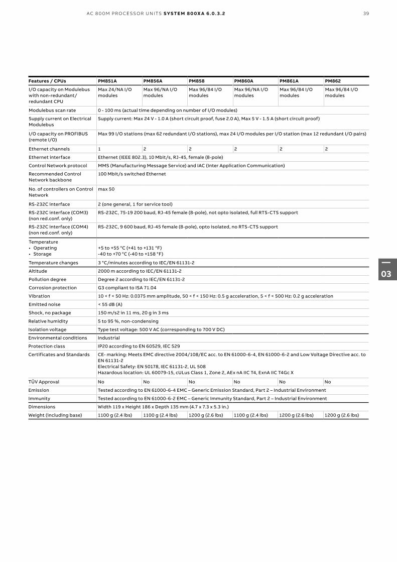
Features / CPUs PM851A PM856A PM858 PM860A PM861A PM862
I/O capacity on Modulebus with non-redundant/redundant CPU
Max 24/NA I/O modules
Max 96/NA I/O modules
Max 96/84 I/O modules
Max 96/NA I/O modules
Max 96/84 I/O modules
Max 96/84 I/O modules
Modulebus scan rate 0 - 100 ms (actual time depending on number of I/O modules)
Supply current on ElectricalModulebus
Supply current: Max 24 V - 1.0 A (short circuit proof, fuse 2.0 A), Max 5 V - 1.5 A (short circuit proof)
I/O capacity on PROFIBUS(remote I/O)
Max 99 I/O stations (max 62 redundant I/O stations), max 24 I/O modules per I/O station (max 12 redundant I/O pairs)
Ethernet channels 1 2 2 2 2 2
Ethernet interface Ethernet (IEEE 802.3), 10 Mbit/s, RJ-45, female (8-pole)
Control Network protocol MMS (Manufacturing Message Service) and IAC (Inter Application Communication)
Recommended ControlNetwork backbone
100 Mbit/s switched Ethernet
No. of controllers on Control Network
max 50
RS-232C interface 2 (one general, 1 for service tool)
RS-232C interface (COM3) (non red.conf. only)
RS-232C, 75-19 200 baud, RJ-45 female (8-pole), not opto isolated, full RTS-CTS support
RS-232C interface (COM4) (non red.conf. only)
RS-232C, 9 600 baud, RJ-45 female (8-pole), opto isolated, no RTS-CTS support
Temperature• Operating• Storage
+5 to +55 °C (+41 to +131 °F)-40 to +70 °C (-40 to +158 °F)
Temperature changes 3 °C/minutes according to IEC/EN 61131-2
Altitude 2000 m according to IEC/EN 61131-2
Pollution degree Degree 2 according to IEC/EN 61131-2
Corrosion protection G3 compliant to ISA 71.04
Vibration 10 < f < 50 Hz: 0.0375 mm amplitude, 50 < f < 150 Hz: 0.5 g acceleration, 5 < f < 500 Hz: 0.2 g acceleration
Emitted noise < 55 dB (A)
Shock, no package 150 m/s2 in 11 ms, 20 g in 3 ms
Relative humidity 5 to 95 %, non-condensing
Isolation voltage Type test voltage: 500 V AC (corresponding to 700 V DC)
Environmental conditions Industrial
Protection class IP20 according to EN 60529, IEC 529
Certificates and Standards CE- marking: Meets EMC directive 2004/108/EC acc. to EN 61000-6-4, EN 61000-6-2 and Low Voltage Directive acc. to EN 61131-2Electrical Safety: EN 50178, IEC 61131-2, UL 508Hazardous location: UL 60079-15, cULus Class 1, Zone 2, AEx nA IIC T4, ExnA IIC T4Gc X
TÜV Approval No No No No No No
Emission Tested according to EN 61000-6-4 EMC – Generic Emission Standard, Part 2 – Industrial Environment
Immunity Tested according to EN 61000-6-2 EMC – Generic Immunity Standard, Part 2 – Industrial Environment
Dimensions Width 119 x Height 186 x Depth 135 mm (4.7 x 7.3 x 5.3 in.)
Weight (including base) 1100 g (2.4 lbs) 1100 g (2.4 lbs) 1200 g (2.6 lbs) 1100 g (2.4 lbs) 1200 g (2.6 lbs) 1200 g (2.6 lbs)
39
—03
AC 8 0 0 M PR O CE SSO R U N ITS S YS TE M 8 0 0X A 6 .0. 3 . 2

Features / CPUs PM864A PM865 PM866A PM867 PM891
Processor Unit PM864AK01 incl:1 PM864A CPU and required optional itemsPM864AK02 incl:2 PM864AK01
PM865K01 incl:1 PM865 CPU and required optional itemsPM865K02 incl:2 PM865K01
PM866AK01 incl:1 PM866A CPU and required optional itemsPM866AK02 incl:2 PM866AK01
PM867K01 incl:1 PM867 CPU and required optional itemsPM867K02 incl:2 PM867K01
PM891K01 incl:1 PM891 CPU and required optional itemsPM891K02 incl:2 PM891K01
Optional items (partly included in Processor Units, see Price List)
TP830 Baseplate, TP850 CEX-bus term., TK850 CEX-bus cable, TB807, Modulebus term, Battery RAM backup, TB852/TB853 RCU-link term, TB851/TB855/TB856 RCU-link cable, SB822 External Battery Unit, TK212A Tool cable, TC562 Short Distance Modem, TK853V020 Modem cable, BC810K02, BC820K02, CEX-bus Interconnection unit; TK851V010 Connection cable, SD831/SD832/SD833 Power Supply, SS832 Voting Unit, Mains Breaker Kit, SM811 Supervisory Module and SM812 Supervisory Module.
High Integrity Controller No Yes No Yes No
Clock frequency 96 MHz 96 MHz 133 MHz 133 MHz 450 MHz
Memory (RAM) From 5.1 FP4
32 MB 32 MB 64 MB 64 MB 256 MB
RAM available for application
23.522 MB 22.184 MB 51.389 MB 46.559 MB 208.985 MB
Processor type MPC862 MPC862P MPC866 MPC866 MPC8270
Flash memory for storage of application and data
Yes No Yes No Yes
CPU redundancy support Yes Yes Yes Yes Yes
Switch over time in red. conf.
max 10 ms max 10 ms max 10 ms max 10 ms max 10 ms
Performance, 1000 boolean operations (a:=b and c)
0.15 ms 0.17 ms 0.09 ms 0.09 ms 0.043 ms
No. controllers per control projects
32
No. of applications per control project
1024
No. of applications per controller
32
No. of programs per application
64
No. of tasks per controller 32
Number of different cycle times
32
Cycle time per applicationprograms
Down to 1 ms
Flash PROM for firmware storage
2 MB 4 MB 4 MB 18 MB 16 MB
Power supply 24 V DC (19.2-30 V DC) max 5 % ripple acc. to IEC 61131-2
Power consumption +24 V typ/max 287/487 mA typ/max 287/487 mA typ/max 210/360 mA typ/max 210/360 mA typ/max 660/750 mA
Power dissipation typ. 6.9 W 6.9 W 5.1 W 5.1 W 15.8 W
Power Reservoir Internal 5 ms power reservoir, sufficient for the CPU to make a controlled power down
Power supply connector Detachable 4-pole screw terminal block
Redundant power supplystatus inputs
Yes: 2 inputs designated SA, SB (Max 30 V, high level >15 V, low level < 8 V)
Built-in back-up battery Type: Lithium, 3.6 V, 0.95 Ah, size 1/2 AA, 0.3 g Lithium content No
Real-time clock stability 100 ppm (approx. 1 h/year) 50 ppm
Clock synchronization 1 ms between AC 800M controllers by CNCP protocol
Comm. modules on CEX bus 12 12 12 12 12
Supply current on CEX bus Supply current: Max 24 V - 2.4 A (fuse 3.15 A fast, PM891 has an embedded auto fuse)
I/O clusters on Modulebus with non-redundant CPU
1 el. + 7 opt. 1 el. + 7 opt. 1 el. + 7 opt. 1 el. + 7 opt. 0 el. + 7 opt.
I/O clusters on Modulebus with redundant CPU
0 el. + 7 opt. 0 el. + 7 opt. 0 el. + 7 opt. 0 el. + 7 opt. 0 el. + 7 opt.
I/O capacity on Modulebus with non-redundant/redundant CPU
Max 96/84 I/O modules
Max 96/84 I/O modules
Max 96/84 I/O modules
Max 96/84 I/O modules
Max 84/84 I/O modules
—AC 800M Controllers selection guide
40
—03
S YS TE M 8 0 0X A 6 .0. 3 . 2 AC 8 0 0 M PR O CE SSO R U N ITS

Features / CPUs PM864A PM865 PM866A PM867 PM891
Modulebus scan rate 0 - 100 ms (actual time depending on number of I/O modules), 0 - 300 for PM865 and PM867
Supply current on ElectricalModulebus
Supply current: Max 24 V - 1.0 A (short circuit proof, fuse 2.0 A), Max 5 V - 1.5 A (short circuit proof)
24 V : max 1.0 A 5 V : max 1.5 A
Not supported
I/O capacity on PROFIBUS(remote I/O)
Max 99 I/O stations (max 62 redundant I/O stations), max 24 I/O modules per I/O station (max 12 redundant I/O pairs)
Ethernet channels 2 2 2 2 2
Ethernet interface Ethernet (IEEE 802.3), 10 Mbit/s, RJ-45, female (8-pole) 10/100 Mbit/s
Control Network protocol MMS (Manufacturing Message Service) and IAC (Inter Application Communication)
Recommended ControlNetwork backbone
100 Mbit/s switched Ethernet
No of controllers on Control Network
max 50
RS-232C interface 2 (one general, 1 for service tool) 1 for service tool (COM 4)
RS-232C interface (COM3) (non red.conf. only)
RS-232C, 75-19 200 baud, RJ-45 female (8-pole), not opto isolated, full RTS-CTS support Not supported
RS-232C interface (COM4) (non red.conf. only)
RS-232C, 9 600 baud, RJ-45 female (8-pole), opto isolated, no RTS-CTS support
Temperature• Operating• Storage
+5 to +55 °C (+41 to +131 °F)-40 to +70 °C (-40 to +158 °F)
Temperature changes 3 °C/minutes according to IEC/EN 61131-2
Altitude 2000 m according to IEC/EN 61131-2
Pollution degree Degree 2 according to IEC/EN 61131-2
Corrosion protection G3 compliant to ISA 71.04
Vibration 10 < f < 50 Hz: 0.0375 mm amplitude, 50 < f < 150 Hz: 0.5 g acceleration, 5 < f < 500 Hz: 0.2 g acceleration
Emitted noise < 55 dB (A)
Shock, no package 150 m/s2 in 11 ms, 20 g in 3 ms
Relative humidity 5 to 95 %, non-condensing
Isolation voltage Type test voltage: 500 V AC (corresponding to 700 V DC)
Environmental conditions Industrial
Protection class IP20 according to EN 60529, IEC 529
Certificates and Standards CE- marking: Meets EMC directive 2004/108/EC acc. to EN 61000-6-4, EN 61000-6-2 and Low Voltage Directive acc. to EN 61131-2Electrical Safety: EN 50178, IEC 61131-2, UL 508Hazardous location: UL 60079-15, cULus Class 1, Zone 2, AEx nA IIC T4, ExnA IIC T4Gc X
TÜV Apparoval No IEC 61508 SIL3 No IEC 61508 SIL3 No
Emission Tested according to EN 61000-6-4 EMC – Generic Emission Standard, Part 2 – Industrial Environment
Immunity Tested according to EN 61000-6-2 EMC – Generic Immunity Standard, Part 2 – Industrial Environment
Dimensions Width 119 x Height 186 x Depth 135 mm (4.7 x 7.3 x 5.3 in.) Width 174 x Height 186 x Depth 94 mm
Weight (including base) 1100 g (2.4 lbs) 1200 g (2.6 lbs) 1200 g (2.6 lbs) 1200 g (2.6 lbs) 1600 g (3.5 lbs)
41
—03
AC 8 0 0 M PR O CE SSO R U N ITS S YS TE M 8 0 0X A 6 .0. 3 . 2

—AC 800M HardwareHardware Upgrade orders
AC 800M Hardware
Please note that this Hardware Price List can be used for both System 800xA v5 and System 800xA v6. Nolicenses are included for the items in this Price List. Licenses for running the Hardware can be purchasedusing the Software Expansion Lists.
Hardware Upgrade orders
For Hardware Upgrade orders please send your inquiry to Service Center mail box: [email protected]
ISA-S71.04 level G3 Compliamce
Modules are compliant to ISA-S71.04 level G3, unless explicitly stated differently.
Extended Warranty for AC 800M Hardware
We can offer an extended warranty for one, two, or three years in addition to normal warranty conditions for AC 800M Hardware. See price list Extended Warranty 3BSE049908.
174
186
94119 (4.7) 135 (5.3)
186
(7.3
)
—Measurements
—CPU
—PM891
42
—03
S YS TE M 8 0 0X A 6 .0. 3 . 2 AC 8 0 0 M PR O CE SSO R U N ITS

—AC 800M HardwareSystem Units
—AC 800M HardwareAC 800M Processor Units
System Units
The Tool Cable TK212A is most useful when working with AC 800M. Please order a cable (Item P215) together with your first order of PM851AK01, PM856AK01, PM858K01, PM858K02, PM860AK01, PM861AK01, PM861AK02, PM862K01, PM862K02, PM864AK01, PM864AK02, PM865K01, PM865K02, PM866K01, PM866K02, PM866AK01, PM866AK02, PM867K01, PM867K02, PM891K01 or PM891K02.
AC 800M Processor Units Article no.
PM851AK01 Processor UnitPackage including:• PM851A, CPU• TP830, Baseplate, width=115 mm• TB850, CEX-bus terminator• TB807, ModuleBus terminator• Battery for memory backup (4943013-6)• No license included.
3BSE066485R1
PM856AK01 Processor UnitPackage including:• PM856A, CPU• TP830, Baseplate, width=115 mm• TB850, CEX-bus terminator• TB807, ModuleBus terminator• Battery for memory backup (4943013-6)• No license included.
3BSE066490R1
43
—03
AC 8 0 0 M PR O CE SSO R U N ITS S YS TE M 8 0 0X A 6 .0. 3 . 2

—AC 800M HardwareAC 800M Processor Units
AC 800M Processor Units Article no.
PM858K01 Processor UnitPackage including:• PM858, CPU• TP830, Baseplate, width =115mm• TB850, CEX-bus terminator• TB807, ModuleBus terminator• TB852, RCU-Link terminator• Battery for memory backup (4943013-6)• No license included.
3BSE082895R1
PM858K02 Redundant Processor UnitsPackage including:• 2 pcs PM858, CPU• 2 pcs TP830, Baseplate, width =115mm• 2 pcs TB807, ModuleBus terminator• 1 pcs TK850, CEX-bus expansion cable• 1 pcs TK851, RCU-Link cable• 2 pcs Battery for memory backup (4943013-6)• No license included.
3BSE082896R1
PM860AK01 Processor UnitPackage including:• PM860A, CPU• TP830, Baseplate, width=115 mm• TB850, CEX-bus terminator• TB807, ModuleBus terminator• Battery for memory backup (4943013-6)• No license included.
3BSE066495R1
PM862K01 Processor UnitPackage including:• PM862, CPU• TP830, Baseplate, width =115mm• TB850, CEX-bus terminator• TB807, ModuleBus terminator• TB852, RCU-Link terminator• Battery for memory backup (4943013-6)• No license included.
Only compatible with 800xA 6.0.2, Compact Control Builder6.0.0-1 and onwards. Please see Product Update for more information.
3BSE076940R1
PM862K02 Redundant Processor UnitsPackage including:• 2 pcs PM862, CPU• 2 pcs TP830, Baseplate, width =115mm• 2 pcs TB807, ModuleBus terminator• 1 pcs TK850, CEX-bus expansion cable• 1 pcs TB851, RCU-Link cable• 2 pcs Battery for memory backup (4943013-6)• No license included.
Only compatible with 800xA 6.0.2, Compact Control Builder6.0.0-1 and onwards. Please see Product Update for more information.
3BSE081636R1
44
—03
S YS TE M 8 0 0X A 6 .0. 3 . 2 AC 8 0 0 M PR O CE SSO R U N ITS

45
—03
AC 8 0 0 M PR O CE SSO R U N ITS S YS TE M 8 0 0X A 6 .0. 3 . 2
AC 800M Processor Units Article no.
PM866AK01 Processor UnitPackage including:• PM866A, CPU• TP830, Baseplate, width =115mm• TB850, CEX-bus terminator• TB807, ModuleBus terminator• TB852, RCU-Link terminator• Battery for memory backup (4943013-6)• No license included.
3BSE076939R1
PM866AK02 Redundant Processor UnitsPackage including:• 2 pcs PM866A, CPU• 2 pcs TP830, Baseplate, width =115mm• 2 pcs TB807, ModuleBus terminator• 1 pcs TK850, CEX-bus expansion cable• 1 pcs TB851, RCU-Link cable• 2 pcs Battery for memory backup (4943013-6)• No license included.
3BSE081637R1
PM891K01 Processor UnitPackage including:• PM891 CPU Module• TB850, CEX-bus terminator• TB853, RCU Control Link Terminator• No license included
3BSE053241R1
PM891K02 Redundant Processor UnitPackage including:• 2 pcs PM891K01 Processor Unit• 1 pcs TK850V007 CEX-bus Extension Cable• 1 pcs TK855 RCU Data Link Cable• 1 pcs TK856 RCU Control Link Cable• No license includedPlease note: The BC810K02 is not included in the PM891K02Redundant Processor Unit kit. In order to make hot replacement of PM891 Processor Unit possible, the BC810K02 is required and has to be ordered separately.
3BSE053242R1
SB822 Rechargeable battery unitExternal DIN-rail mounted rechargeable battery unit including lithium-ion battery, 24V DC connector and connection cable TK821V020. Width=85 mm.Equivalent amount of Lithium metal=0,8g (0,03oz)
3BSE018172R1
—AC 800M HardwareAC 800M Processor Units

AC 800M High Integrity Units Article no.
The PM865 or PM867 CPU units are intended for use in High Integrity systems. Local organizations must comply with the Qualifications to secure successful sales of ABB safety systems, to order safety equipment. Ref doc, 3BSE047224
PM865K01 Processor UnitPackage including:• PM865, CPU• TP830, Baseplate, width =115mm• TB850, CEX-bus terminator• TB807, ModuleBus terminator• TB852, RCU-Link terminator• Battery for memory backup (4943013-6)• No license includedNote! This part is not RoHS 2 2011/65/EU compliant.This is a spare part for systems placed on the market before July 22, 2017 and may only be ordered for repair, reuse, updating of functionalities or upgrading of capacity. For new installations, please order PM867K01 instead.
3BSE031151R1
PM865K02 Redundant Processor UnitPackage including:• 2 pcs PM865K01, Processor unit• 1 pcs TK850, CEX-bus expansion cable• 1 pcs TK851, RCU-Link cable• No license includedNote! This part is not RoHS 2 2011/65/EU compliant.This is a spare part for systems placed on the market beforeJuly 22, 2017 and may only be ordered for repair, reuse, updating of functionalities or upgrading of capacity.For new installations, please order PM867K02 instead
3BSE031150R1
PM867K01 Processor UnitPackage including:• PM867, CPU• TP830, Baseplate, width =115mm• TB850, CEX-bus terminator• TB807, ModuleBus terminator• TB852, RCU-Link terminator• Battery for memory backup (4943013-6)• No license included.
Only compatible for 800xA 6.0.2 and onwards. Please seeProduct Update for more information.
3BSE076355R1
PM867K02 Redundants Processor UnitsPackage including:• 2 pcs PM867, CPU• 2 pcs TP830, Baseplate, width =115mm• 2 pcs TB807, ModuleBus terminator• 1 pcs TK850, CEX-bus expansion cable• 1 pcs TB851, RCU-Link cable• 2 pcs Battery for memory backup (4943013-6)• No license included.
Only compatible for 800xA 6.0.2 and onwards. Please seeProduct Update for more information.
3BSE081638R1
SM811K01 Safety CPU module kitCollaborating safety CPU with PM865 processor unit. Connects to CEX bus after BC810 CEX bus interconnection box. Including:• SM811, Safety Module• TP868, Baseplate, width=60mm• TK852V10, Syncronization link cable
Note! This part is not RoHS 2 2011/65/EU compliant. This is a spare part for systems placed on the market before July 22, 2017 and may only be ordered for repair, reuse, updating of functionalities or upgrading of capacity. For new installations, please order SM812K01 instead.
3BSE018173R1
—System UnitsAC 800M High Integrity Units
46
—03
S YS TE M 8 0 0X A 6 .0. 3 . 2 AC 8 0 0 M PR O CE SSO R U N ITS

AC 800M High Integrity Units Article no.
SM812K01 Safety CPU module kitCollaborating safety CPU with PM867 processor unit. Package including:• SM812, Safety Module• TP868, Baseplate, width=60mm• TK852V10, Syncronization link cableOnly compatible for 800xA 6.0.2 and onwards. Please seeProduct Update for more information.
3BSE072270R1
SS823 Voting DeviceRequired in a High Integrity 800xA system.One per power supply unit, also at redundant configurations. Input d.c. 24 V. Dual 24 V to single 24 V, 20A.DIN rail mounted.
3BSE038226R1
—System UnitsExtra Batteries
—CommunicationControl Network
—CommunicationSerial Interfaces on TP830
Extra Batteries
For extra Lithium batteries (4943013-6), please refer to Business Online.
Control Network
No articles, such as cables, hubs, switches etc, for Control Network are included in this price list. Please refer to Product Guide AC 800M, for recommended articles. Recommended network components are available in 800xA Networks price list, 3BSE081392
Serial Interfaces on TP830 Article no.
RS232-C interfaces for protocols COMLI, MODBUS, Siemens 3964R, the free-programmable serial protocol etc. Also for connection of engineering tool.
TK212A Tool cableRJ45 (male) to Dsub-9 (female), length 3 m. RJ45 8P8C plug (with shell). Cable : UL2464 26 AWG x 8C.
3BSC630197R1
TC562 Short Distance Modem, G1 CompliantLength < 10 km. Point-to-point up to 1 km at 19200 bps. Power 24V d.c. Width=55 mm
3BSC630049R1
TK853V020 Modem CableLength 2 m
3BSC950201R1
47
—03
AC 8 0 0 M PR O CE SSO R U N ITS S YS TE M 8 0 0X A 6 .0. 3 . 2

Supported Communication modules
PROFIBUS DP
FOUNDATION FIELDBUS
RS-232 C MB300 INSUM Drivebus S100 I/O Genius TRIO I/O
Satt I/O MODBUS TCP
IEC 61850
Module CI854A/CI854B
CI860 CI853 CI855 CI857 CI858 CI856 CI862 CI865 CI867 CI868
Protocol DP-V1(PA viaLinkingDevice)
FF HSE(H1 viaLinkingDevice)
MODBUS RTU master, COMLI master/ slave, Siemens 3964R master, User defined protocols
MasterBus300
IEEE802.3
ABB’sDriveBus
ABB’sS100 I/O
Genius ABB’sSatt I/O
MODBUSTCP
IEC61850
Master or slave Master Master Master/slave Master/slave
Master Master Master Master Master Master/slave
Number of channels
2 1 2 2 1 1 main, 2 aux
1 1 1 2 1
Max units on CEX bus
12 12 12 12 6 2 12 12 4 12 12
Transmission speed
9.6 - 12,000 kbit/s
10/100 Mbit/s
75 - 19200 b/s
10 Mbit/s, 200 Datasets/s
10 Mbit/s
4 Mbit/s - 38.4 -153.6kbit/s
- 10/100Mbit/s(Ch1),10 Mbit/s(Ch2)
10/100Mbit/s
Cable redundancy
Yes No No Yes No No No No No No No
Module redundancy
Yes Yes No No No No No No No Yes No
Hot Swap Yes Yes Yes Yes Yes Yes Yes Yes Yes Yes Yes
Used together with High Integrity Controller
Yes No Yes Yes Yes No No No No Yes Yes
Connectors DB female (9-pin )
RJ-45 female (8-pin)
RJ-45 female (8-pin)
RJ-45 female (8-pin)
RJ-45 female (8-pin)
Fiberoptic Miniribbon (36-pin)
Phoenix (4-pin)
BNC RJ-45 female (8-pin)
RJ-45 female (8-pin)
24 V current consumption
typ190 mA
typ100 mA
typ100 mA
typ150 mA
typ150 mA
typ200 mA
typ200 mA
typ190 mA
typ120 mA
typ160 mA
typ160 mA
Protection class IP20 according to EN60529, IEC 529
Certification
• CE-marked Yes Yes Yes Yes Yes Yes Yes Yes Yes Yes Yes
• UL 508 Yes Yes Yes Yes Yes Yes Yes No Yes Yes Yes
• UL 60079-15 (Class 1 Zone 2)
Yes Yes Yes Yes Yes Yes Yes No Yes Yes Yes
Dimensions Width 58 x Height 186 x Depth 135 mm (2.3 x 7.3 x 5.3 in.)
Weight(including base)
700 g(1.5 lbs)
455 g(0.9 lbs)
520 g(1.2 lbs)
700 g(1.5 lbs)
600 g(1.3 lbs)
700 g(1.5 lbs)
600 g(1.3 lbs)
600 g(1.3 lbs)
600 g(1.3 lbs)
700 g(1.5 lbs)
700 g(1.5 lbs)
—Communication Interface selection guide
48
—03
S YS TE M 8 0 0X A 6 .0. 3 . 2 AC 8 0 0 M PR O CE SSO R U N ITS

Supported Communication modules AF100 PROFINET IO EtherNet/IP DeviceNet
Module CI869 CI871 CI873
Protocol Advant Fieldbus 100 PROFINET IO EtherNet/IP DeviceNet (via LD800DN)
Master or slave Slave Master Master
Number of channels 2 1 1
Max units on CEX bus 4 12 4
Transmission speed Up to 500 Kbit/s 10/100 Mbit/s 10/100 Mbit/s
Cable redundancy Yes No No
Module redundancy Yes No No
Hot Swap Yes Yes Yes
Used together with High Integrity Controller
Yes Yes Yes
Connectors Phoenix (4-pin) RJ-45 female (8-pin) RJ-45 female (8-pin)
24 V current consumption typ 160 mA typ 160 mA typ 160 mA
Protection class IP20 according to EN60529, IEC 529
UL 508 Yes Yes Yes
UL 60079-15 (Class 1 Zone 2) Yes Yes Yes
Dimensions Width 58 x Height 186 x Depth 135 mm (2.3 x 7.3 x 5.3 in.)
Weight (including base) 700 g (1.5 lbs) 700 g (1.5 lbs) 700 g (1.5 lbs)
49
—03
AC 8 0 0 M PR O CE SSO R U N ITS S YS TE M 8 0 0X A 6 .0. 3 . 2

Serial Communication Interface Article no.
RS232-C interfaces for protocols COMLI, MODBUS, Siemens 3964R, the free-programmable serial protocol etc.
CI853K01 Dual RS232-C interfacePackage including:• CI853, Communication Interface• TP853, Baseplate, width = 60 mm
3BSE018103R1
PROFIBUS DP Article no.
The required PROFIBUS network components (Linking Devices, etc) must be ordered from price list 3BDD 013 232, PROFIBUS Network Components.
CI854AK01 Profibus Communication InterfacePackage including:• CI854A, Communication Interface• TP854, Baseplate, width = 60 mm
3BSE030220R1
CI854BK01 Profibus Communication InterfacePackage including:• CI854B, Communication Interface• TP854, Baseplate, width = 60 mm
3BSE069449R1
MODBUS TCP Article no.
CI867K01 Modbus TCP InterfacePackage including:• CI867, Communication Interface• TP867, Baseplate, width = 60mm
3BSE043660R1
PROFINET IO Article no.
CI871K01 PROFINET IO Communication InterfacePackage including:• CI871, Communication Interface• TP867, Baseplate, width = 60 mm
3BSE056767R1
—CommunicationSerial Communication Interface
—CommunicationMODBUS TCP
—CommunicationPROFIBUS DP
—CommunicationPROFINET IO
50
—03
S YS TE M 8 0 0X A 6 .0. 3 . 2 AC 8 0 0 M PR O CE SSO R U N ITS

IEC 61850 Article no.
For order of IEC 61850 related products, local organizations must comply with the Demands on the Purchaser to secure successful sales of IEC 61850 with System 800xA. Ref doc, 3BSE058798.
CI868K01 IEC61850-Ed1 (Edition 1) Communication Package including:• CI868, Communication Interface• TP867, Baseplate, width=60mm
3BSE048845R1
FOUNDATION Fieldbus Article no.
The required FOUNDATION Fieldbus network components (Linking devices, etc) must be ordered from price list 3BDD 013 231, FOUNDATION Fieldbus Network Components.
CI860K01 FOUNDATION Fieldbus HSE InterfacePackage including:• CI860, Communication Interface• TP860, Baseplate, width = 60 mm
3BSE032444R1
Ethernet/IP Article no.
CI873K01 Ethernet/IP Communication InterfacePackaging including:• CI873, Communication Interface• TP867, Baseplate width=60mm
3BSE056899R1
LD 800DN EtherNet/IP to DeviceNet Linking Device, G1 CompliantPackage including:1 pcs LD 800DN1 pcs Installation Guide2 pcs Termination resistors for DeviceNet, 1/4 W, 121 OhmMay only be used with CI873 Communication Interface.
3BSC690164R1
—CommunicationFOUNDATION Fieldbus
—CommunicationIEC 61850
—CommunicationEthernet/IP
51
—03
AC 8 0 0 M PR O CE SSO R U N ITS S YS TE M 8 0 0X A 6 .0. 3 . 2

Advant Fieldbus 100 Article no.
CI869K01 AF 100 Communication InterfacePackage including:• CI869, Communication Interface• TP869, Baseplate, width=60mm
3BSE049110R1
—CommunicationAdvant Fieldbus 100
—CommunicationMasterBus 300
—CommunicationS100 I/O Bus
MasterBus 300 Article no.
CI855K01 MB 300 Dual Ethernet port Package including:• CI855, MB300 Interface Module• TP853, Base plate
3BSE018106R1
S100 I/O Bus Article no.
CI856K01 S100 I/O InterfaceInstalled on DIN rail. Communication bridge between AC800M and S100 system. Package including:• CI856, Communication Interface• TP856, Baseplate, width = 60mm
3BSE026055R1
52
—03
S YS TE M 8 0 0X A 6 .0. 3 . 2 AC 8 0 0 M PR O CE SSO R U N ITS

—CommunicationTRIO
—CommunicationSatt I/O
—CommunicationINSUM
INSUM Article no.
CI857K01 INSUM Ethernet InterfacePackage including:• CI857, Communication Interface• TP853, Baseplate, width = 60 mm
3BSE018144R1
TRIO Article no.
CI862K01 TRIO Interface Kit, G1 CompliantPackage including:• CI862, Communication Interface• TP862, Baseplate, width = 60 mm
3BUA000037R1
CI862K02 Redundant TRIO Interface Kit with Connection Cable, G1 CompliantPackage including:• 2 x CI862, Communication Interface• 2 x TP862, Baseplate, width = 60 mm• TK862 Cable, 1 m
3BUA000111R1
Satt I/O Article no.
For SATT 19" rack I/O and S200 I/O via ControlNet. For additional Satt 19" rack I/O components, see price list 3BSE014353 (Interface) in price book 3BSE014360 (SattLine/SattCon).
CI865K01Communication Interface Module for Satt I/OPackage including:• - CI865, Communication Interface• - TP865, Baseplate, width = 60 mm
3BSE040795R1
53
—03
AC 8 0 0 M PR O CE SSO R U N ITS S YS TE M 8 0 0X A 6 .0. 3 . 2

—CommunicationBus Accessories
Bus Accessories Article no.
TK850V007 CEX-Bus Extension CableLength = 0.7 m
3BSC950192R1
TB850 CEX-Bus TerminatorWith 25-pin DB25P male connector. With screw fixing.
3BSC950193R1
TB851 CEX-Bus TerminatorWith 25-pin DB25S female connector. With screw fixing.
3BSC950194R1
BC810K02 CEX-bus Interconnection UnitIncluding:• BC810, Interconnection Unit, 2 units• TP857, Baseplate, width = 60 mm, 2 units• TK851, Interconnection Cable• TB850, CEX-Bus Terminator, 2 units
3BSE031155R1
BC820K02 RCU-Link and CEX-Bus Interconnection UnitsAllows AC 800M redundant PM858, PM862 or PM866 (A) pair to be up to 200 m apart, cables not included.Including:• BC820, RCU-Link and CEX-Bus Interconnection Unit, 2
units• TP850, Baseplate, width=60mm, 2 units• TK857 RCU-Link Cable for BC820, 2 units• TB850, CEX-Bus Terminator, 2 unitsPM866 PR:H or later is required.
3BSE071500R1
TK851V010 Connection CableLength = 1.0 m. Used as:• RCU Link Cable• BC810 Interconnection Cable
3BSC950262R1
TB852 RCU Link Terminator 3BSC950263R1
TB853 RCU Control Link Terminator 3BSE057022R1
TK855 RCU Data Link CableLength = 1.0 m. Used as: RCU Data Link Cable
3BSC950356R1
TK856 RCU Control Link CableLength = 1.0 m. Used as: RCU Control Link Cable
3BSE057021R1
TK857V003 RCU Link CableLength = 0.3 m.Used as: RCU Link cable
3BSC950375R1
—CommunicationDriveBus
DriveBus Article no.
CI858K01 DriveBus InterfacePackage including:• CI858, Communication Interface• TP858, Baseplate, width = 60 mm
3BSE018135R1
54
—03
S YS TE M 8 0 0X A 6 .0. 3 . 2 AC 8 0 0 M PR O CE SSO R U N ITS

—AC 800M Power supply and Voters selection guide
Feature SD822Z SD831 SD832 SD833 SD834 SS822Z SS832 SS823
Rated output current 5 A 3 A 5 A 10 A 20 A 20 A 10 A (20 A in parallell operation)
20 A
Rated output power 120 W 72 W 120 W 240 W 480 W - - -
Rated output voltage d.c. 24 V d.c. 24 V d.c. 24 V d.c. 24 V d.c. 24 V - - -
Rated input power 280 VA 135 W 134/143 VA 240/283 VA 447/514 VA 547/568 VA 500 W 240 W (480 W in parallell operation)
500 W
Mains/input voltage, nominal
115/230 V a.c.
225-250 V d.c.
100-240 V a.c.
110-300 V d.c.
100-120 V a.c.200-240 V a.c.Auto-select input
100-120 V a.c.200-240 V a.c.Auto-select input
100-240 V a.c.
110-150 V d.c
2x24 V d.c. 2x24 V d.c(1x24 V d.c in parallell operation)
1x24 V d.c
Mains voltage variation allowed
85 - 110% 90-264 V a.c.88-375 V d.c.
90-132 V a.c.180-264 V a.c.
90-132 V a.c.180-264 V a.c.
85-276 V a.c.88-375 V d.c.
- - -
Mains/input voltage, max. (a.c.= 45-65 Hz)
138/275 V a.c.375 V d.c.
264-300 V a.c.
264-300 V a.c.
264-300 V a.c.
264-300 V a.c.
60 V d.c. 60 V d.c. 60 V d.c.
Primary peak inrush current at power on
Typ 15 A <28/<54 A <10 A <10 A <13 A - - -
Applications SELV and PELV
SELV and PELV
SELV and PELV
SELV and PELV
SELV and PELV
- - -
Load sharing Two in parallell
- - - Parallell connection
Two in parallell
Two in parallell
Yes
Power Factor (at rated output power)
0.61/0.56 0.56/0.47 0.59/0.51 0.95/0.90 - - -
Heat dissipation 13.3 W 10/8 W 14/13 W 24/22 W 40/32 W 10 W at 20 A and 2,5 W at 5 A
9 W (18 W) 24 W at 20 A and 6 W at 5 A
Efficiency factor 88 % 88/89.8 % 89.4/90.2 % 91/91.6 % 92.4/93.9 % - - -
Output voltage regulation at max. current
+- 2% < 50 mV / < 100 mV
< 70 mV / < 100 mV s
< 70 mV / < 100 mV
< 10 mV / < 100 mV
0,5 V lower than input
0.85 V lower than input
1.2 V lower than input
Ripple (peak to peak) < 50 mV < 50 mV < 50 mV < 50 mV < 100 mV - - -
Secondary voltage holdup time at mains blackout
> 20 ms 29/120 ms 80/78 ms 46/47 ms 32/51 ms - - -
Maximum output current (min)
10 A 3.3 A 6 A At ambient temp < 45 °C
12 A At ambient temp < 45 °C
30 A < 4 s 35 A (Overload)
25 A (Overload)
35 A (Overload)
Maximum ambient temperature
60 °C 60 °C 60 °C 60 °C 60 °C 60 °C 60 °C 55 °C
Primary: Recommended external fuse (1)
10 A 10-20 A 10-20 A 10-20 A 10-20 A - - -
Secondary: Short circuit
< 10 A < 8 A < 14 A < 18 A < 40 A - - -
Secondary: Over-Voltage protection
29 V < 39 V < 39 V < 39 V < 37 V - - < 30 V
Class of protection I PE (Protective Earth) connection required - - -
Protection rating IP20 according to IEC60529
Width 65 mm (2.56”)
32 mm (1.26”) 32 mm (1.26”) 60 mm (2.36”)
82 mm (3.23”) 50 mm (1.97”) 32 mm (1.26”) 116 mm (4.6”)
Depth 110 mm (4.3”)
102 mm (4.02”)
117 mm (4.61”)
117 mm (4.61”)
127 mm (5.0”)
110 mm (4.3”)
117 mm (4.61”)
145 mm (5.8”) including connector
Height 125 mm (4.9”)
124 mm (4.88”)
124 mm (4.88”)
124 mm (4.88”)
124 mm (4.88”)
125 mm (4.9”)
125 mm (4.9”)
132 mm (5.3”)
55
—03
AC 8 0 0 M PR O CE SSO R U N ITS S YS TE M 8 0 0X A 6 .0. 3 . 2

Feature SD822Z SD831 SD832 SD833 SD834 SS822Z SS832 SS823
Mounting spacing Width mm
15 mm (0.59”) 15 mm (0.59”) 15 mm (0.59”) 15 mm (0.59”) 15 mm (0.59”) 15 mm (0.59”) 15 mm (0.59”) 15 mm (0.6”)
Mounting spacing Height mm
25 mm (1”) 40 mm (1.57”) 40 mm (1.57”) 40 mm (1.57”) 40 mm (1.57”) 25 mm (1”) 25 mm (1”) 25 mm (1.2”)
Weight (lbs.) 620 g (1.4 lbs)
430 g (0.9 lbs.)
500 g (1.1 lbs.)
700 g (1.5 lbs.)
1200 g (2.6 lbs.)
630 g (1.4 lbs)
350 g (0.77 lbs.)
870 g (1.9 Ibs.)
Corrosive atmosphere ISA-S71.04
G3 G2 G2 G2 G2 G3 G2 G3
CE mark Yes Yes Yes Yes Yes Yes Yes Yes
El. safety, Haz loc, C1 Zone 2
No No No No No No No No
El. safety, Haz loc, C1 Div 2
No No No No Yes No No No
Electrical safety IEC 61131-2, UL 508, EN 50178 (Note! UL 508 not valid for SS823)
Pollution degree Degree 2, IEC 60664-1
Mechanical operating conditions
EN 61131-2
EMC EN 61000-6-4 and EN 61000-6-2
Overvoltage Categories
Over-voltage Category III (IEC/EN 60664-1)
(1) Microcircuit Breaker (MCB), Characteristic B
—AC 800M Power supply and Voters selection guide
56
—03
S YS TE M 8 0 0X A 6 .0. 3 . 2 AC 8 0 0 M PR O CE SSO R U N ITS

—AC 800M Processor UnitsAC 800M Power supply and Voters
AC 800M Power supply Article no.
SD822Z Power Supply Device, G3 CompliantInput 115/230V a.c. switch selectable, output 24V d.c., 5A.If redundant power application is required connect to SS822Z Voting Unit.. Width = 65 mm. DIN rail mounted.
3BSC610054R1
SD831 Power Supply Device, G2 CompliantInput a.c. 100-240 V or d.c. 110-300 V. Output d.c. 24 V 3A. If redundant power application is required connect toSS8XX. Voting unit. Width = 35mm. DIN rail mounted.
3BSC610064R1
SD832 Power Supply Device, G2 CompliantInput a.c. 100-120/200-240 V. Output d.c. 24 V 5A, auto-select input. If redundant power application is required connect to SD8XX. Voting unit. Width = 35mm. DIN rail mounted.
3BSC610065R1
SD833 Power Supply Device, G2 CompliantInput a.c. 100-120/200-240 V, auto-select input. Output d.c. 24 V 10A. If redundant power application is required connect to SD8XX. Voting unit. Width = 60mm. DIN rail mounted.
3BSC610066R1
SD834 Power Supply Device, G2 CompliantInput a.c. 100-240 V or d.c. 110-150 V. Output d.c. 24 V 20A. If redundant power application is required connect to SS8XX. Voting unit. Width = 85mm. DIN rail mounted.
3BSC610067R1
SS822Z Power Voting Unit, G3 CompliantWith dual 24V d.c 20A inputs, single 24V d.c. 20A output. Each power input supervised. Used if redundant power supply is required. For use with power supply SD822Z.Width = 50 mm. DIN rail mounted.
3BSC610055R1
SS832 Voting Device, G2 CompliantInput d.c. 24 V. Dual 24 V to single 24 V, 2x10A.Width = 35mm. DIN rail mounted.
3BSC610068R1
Mains Breaker Kit for DIN Rail115/230V a.c. with input terminals, breaker and 3 fused (6.3A), double output terminals. Width = 102,5 mm.
3BSE022262R1
—AC 800M Processor UnitsAC 800M Mounting Rails
AC 800M Mounting Rails Article no.
Al-profile with DIN rail and Cable Duct for RE820, mounting 719 mm (28,3”)DIN rail length 683 mm (26,9”)
3BSE022257R1
Al-profile with DIN Rail and Cable Duct for RM550, mounting 592 mm (24”)DIN rail length 556 mm (21,9”)
3BSE022256R1
Al-profile with DIN Rail and Cable Duct, mounting 465 mm (19”)DIN rail length 429 mm (16,9”)
3BSE022255R1
57
—03
AC 8 0 0 M PR O CE SSO R U N ITS S YS TE M 8 0 0X A 6 .0. 3 . 2

S800 I/O is a comprehensive and modular pro-cess I/O system that communicates with parent controllers either direct connected using the Modulebus or over industry-standard field buses. Thanks to its broad connectivity it fits a wide range of process controllers from ABB and others.
By permitting installation in the field, close to sensors and actuators, S800 I/O reduces the installation cost by reducing the cost of cabling. And thanks to features such as hot swap of mo-dules, on-line reconfiguration and redundancy options, it contributes to keeping production – and thereby profits up.
S800 I/O features include:• Comprehensive coverage• Flexible configuration and installation• Ease of set up• Reliability and accuracy
• HART pass-through• Redundancy also on I/O module level• High Integrity I/O modules certified to SIL3• High accuracy time tagging• Defined outputs at communication errors• I/O modules with Intrinsic Safety interfaces
With its cost-effective design and just 59 mm depth installation, S800L I/O modules are the perfect choice for PLC applications. Robust me-chanics, one-piece handling, easy mounting and smart connections save your time in all phases of installation. The comprehensive S800 I/O system consists of more than 40 different module types to respond to every need. Classification of corro-sive protection, electrical safety, hazardous loca-tion and marine certification brings the possi- bility to install S800 I/O in a wide variety of appli-cations. S800 I/O is installed with more than 30 million channels worldwide.
—S800 I/O Modules
—S800 I/O
—S800 I/O
—S800L I/O
58
—04
S YS TE M 8 0 0X A 6 .0. 3 . 2 S 8 0 0 I/O M O D U L E S

—S800 I/O Modules
Digital input modules
DI810 16 channels, 2 groups of 8 channels, 24 V d.c., current sink.
DI811 16 channels, 2 groups of 8 channels, 48 V d.c., current sink.
DI814 16 channels, 2 groups of 8 channels, 24 V d.c., current source.
DI818 32 channels, 2 groups of 16 channels, 24 V d.c., current sink.
DI820 8 channels, separate returns, 110 V d.c., 120 V a.c.
DI821 8 channels, separate returns, 220 V d.c., 230 V a.c.
DI825 With time tagging, 8 channels, separate returns, 125 V d.c.
DI828 16 channels, separate returns, 110 V d.c., 120 V a.c / d.c.
DI830 With time tagging. 16 channels, 2 groups of 8 channels, 24 V d.c., current sink. Resolution: < 0.5 ms.
DI831 With time tagging. 16 channels, 2 groups of 8 channels, 48 V d.c., current sink. Resolution: < 0.5 ms.
DI885 With time tagging & wire-fault detection. 8 channels, common return, 24-48 V d.c., current sink. Resolution: 1 ms.
Pulse input module
DP820 2 channels, separate returns, 0.25 Hz - 1.5 MHz, signal voltage: 5 / 12 V d.c.
DP840 8 channels, extended diagnostics, wire-fault detection, current limited sensor supply, 0.5-20 kHz, 12/24 V d.c or NAMUR, common return.
Digital output modules
DO810 16 channels, 2 groups of 8 channels, 24 V d.c., max 0.5 A d.c., transistor, current source, short-circuit-proof.
DO814 16 channels, 2 groups of 8 channels, 24 V d.c., max 0.5 A, transistor, current sink, short-circuit-proof.
DO815 8 channels, 2 groups of 4 channels, 24 V d.c., max 2 A, transistor, current source, short-circuit-proof, wire-fault detection.
DO818 32 channels, 2 groups of 16 channels, 24 V, max 0.5 A d.c., transistor, current source, short-circuit-proof
DO820 8 channels, separate returns, 5-250 V, max 3 A a.c./d.c., relay (N.O.).
DO821 8 channels, separate returns, 5-250 V, max 3 A a.c./d.c., relay (N.C.).
DO828 16 channels, separate returns, 5-250V a.c. / 5-125V d.c. max 2A a.c./d.c., relay (N.O.).
Analog input modules
AI810 8 channels, single-ended, 0(4)-20 mA, 0(2)-10 V, 12 bits.
AI815 8 channels with HART. 0(4)..20 mA, 0(1)..5 V, 12 bit, single ended, current limited transmitter supply.
AI820 Differential inputs, 4 channels, 0(1)-5 V, ±0(2)-10 V, ±0(4)-20 mA, 14 bits + sign.
AI825 Individually galvanically isolated channels, 4 channels, ±0(2)-10 V, ±0(4)- 20 mA, 14 bits + sign.
AI830A RTD inputs, 8 channels, Pt100, Ni100, Ni120, Cu10, resistor 0-400 ohms, 14 bits, 3-wire.
AI835A TC inputs, 8 channels, (7+ ref. junction), separate returns. TC types B, C, D, E, J, K, L, N, R, S, T, U, - 30…75 mV, 15 bits.
Analog output modules
AO810V2 8 channels, common return, 0(4)-20 mA, 14 bits, load: 850 ohms (short-circuit-proof).
AO815 8 channels with HART. 4..20 mA, 12 bit, load: 750 ohms, common return, short-circuit-proof.
AO820 4 channels, individually galvanically isolated, separate returns, measuring range: ±0(2)-10 V, ±0(4)-20 mA, resolution: 12 bits + sign, load: 500 ohms (current) / 5 kohms (voltage), short-circuit-proof.
Intrinsic-safety modules
DI890 8 channels, separate returns, proximity sensors (NAMUR) or voltage-free contact., current sink, wire-fault detection.
DO890 4 channels, separate returns, load 150-5000 ohms, 11 V @ 40 mA, current source, wire-fault detection, short circuit-proof.
AI890 8 channels, single-ended, 0(4)-20 mA, 12 bits, transmitter power supply.
AI893 8 channels, TC: 7 + ref. junction, sep. returns. TC types B, C, E, J, K, L, N, R, S, T, U, -10…80 mV. RTD: Pt50-1000, Ni100-500, Cu10-100, resistor 0-4000 W, 3-wire. 15 bits + sign.
AI895 8 channels, single-ended, 4-20 mA, 12 bits, transmitter power supply, HART pass-through.
AO890 8 channels, common return, 0(4)-20 mA, 12 bits, load: 725 ohms short-circuit-proof.
AO895 8 channels, common return, 4-20 mA, 12 bits, load: 725 ohms short-circuit-proof, HART pass-through.
Redundant modules
DI840 16 channels, common return, 24 V d.c., current sink, extended diagnostics, time-tagging, current limited sensor supply.
DP840 8 channels, common return, 0.5-20 kHz, 12/24 V d.c or NAMUR, extended diagnostics, wire-fault detection.
DO840 16 channels, common return, 24 V d.c., max. 0,5 A, transistor, current source, short-circuit-proof, extended diagnostics.
AI843 TC input, 8 channels + ref. junction. TC types: B, C, E, J, K, L, N, R, S, T, U, -30…75 mV, 16 bits, extended diagnostics.
AI845 8 channels, 12 bits, 0(4)-20 mA 0(1)-5 V, extended diagnostics, HART pass-through, current limited transmitter supply, single ended.
AO845A 8 channels, 12 bits, common return, 4-20 mA, extended diagnostics, HART pass-through, 750 ohms.
59
—04
S 8 0 0 I/O M O D U L E S S YS TE M 8 0 0X A 6 .0. 3 . 2

—Measurements
S800L modules
DI801 16 channels, 1 group, 24 V d.c., current sink.
DI802 8 channels, 110 V d.c., 150 V a.c.
DI803 8 channels, 220 V d.c., 230 V a.c.
DO801 16 channels, common return, 24 V, max 0.5 A d.c., transistor, current source, short-circuit-proof.
DO802 8 channels, 5-250 V, max 2 A a.c./d.c., relay (N.O.).
AI801 8 channels, single-ended, 0(4)-20 mA, 12 bits.
AO801 8 channels, common return, 0(4)-20 mA, 12 bits, load: less than 750 ohms.
Accessories
TU805K01 For DI801 & DO801. With field power distribution screw terminals. For two or three wire connection.
Environmental Data for S800 I/O
Climatic Operating Conditions +5 to +55 °C (Storage -40 to +70 °C, RH = 5 to 95 % no condensation, IEC/EN 61131-2
Protection class IP20 according to EN 60529, IEC 529
Corrosive protection G3 compliant according to ISA-71.04
Electromagnetic Compatibility and CE-mark Meets EMC directive 2004/108/EC according to EN 61000-6-2 and EN 61000-6-4
Electromagnetic Emission Tested according to EN 61000-6-4 EMC – Generic Emission Standard, Part 2 – Industrial Environment
Electromagnetic Immunity Tested according to EN 61000-6-2 EMC – Generic Immunity Standard, Part 2 – Industrial Environment
Electrical Safety x UL508, IEC/EN 61131-2
Hazardous Classified Locations x C1 Div 2 cULus, C1 Zone 2 cULus, ATEX Zone 2
Safety Integrity (IEC 61508) PM865/SM811, PM867/SM812, AI880A, DI880, DO880: IEC 61508 up to SIL3x) For detailed information on each module, please visit: www.800xahardwareselector.com
127.5 (5.0)84 (3.3)
162
(6.4
)
132 (5.2)120 (4.7)
110
(4.3
)
127.5 (5.0)59 (2.3)
162
(6.4
)
136
(5.4
)
86 (3.4) 58.5 (2.3)
132 (5.2)59 (2.3)
162
(6.4
)
127.5 (5.0)123 (4.8)
162
(6.4
)
132 (5.2)123 (4.8)
162
(6.4
)
132 (5.2)59 (2,3)
194
(7,6
)
Dimensions in mm (in.)
—S800L I/O Modules
—CI810
—CI820, TB815
—Compact I/O
—Redundant I/O
—Intrinsic safety I/O
—Redundant Comm. modules I/O
—CI801, S801L I/O
—Extended I/O
60
—04
S YS TE M 8 0 0X A 6 .0. 3 . 2 S 8 0 0 I/O M O D U L E S

—S800 I/O modules selection guide
NA
MU
R in
put
s
Bin
ary
24 V
Bin
ary
48
V
Bin
ary
110
V
Bin
ary
230
V
Bin
ary
Rel
ay
Ana
log
Uni
po
lar
Ana
log
Bip
ola
r
Tem
per
atur
e R
TD
Tem
per
atur
e T/
C
SOE
HA
RT
Intr
insi
c sa
fety
Red
und
ant
Hig
h in
teg
rity
I/O Features S800Digital input modulesDI810DI811DI814DI818DI820DI821DI825DI828DI830DI831DI840
DI880
DI885DI890Digital output modulesDO810DO814DO815DO818DO820DO821DO828DO840DO880DO890Pulse input modulesDP820DP840Analog input modulesAI810AI815AI820AI825AI830AAI835AAI843AI845AI880AAI890AI893AI895Analog output modulesAO810V2AO815AO820AO845AAO890AO895S800L modulesDI801DI802DI803DO801DO802AI801AO801
61
—04
S 8 0 0 I/O M O D U L E S S YS TE M 8 0 0X A 6 .0. 3 . 2
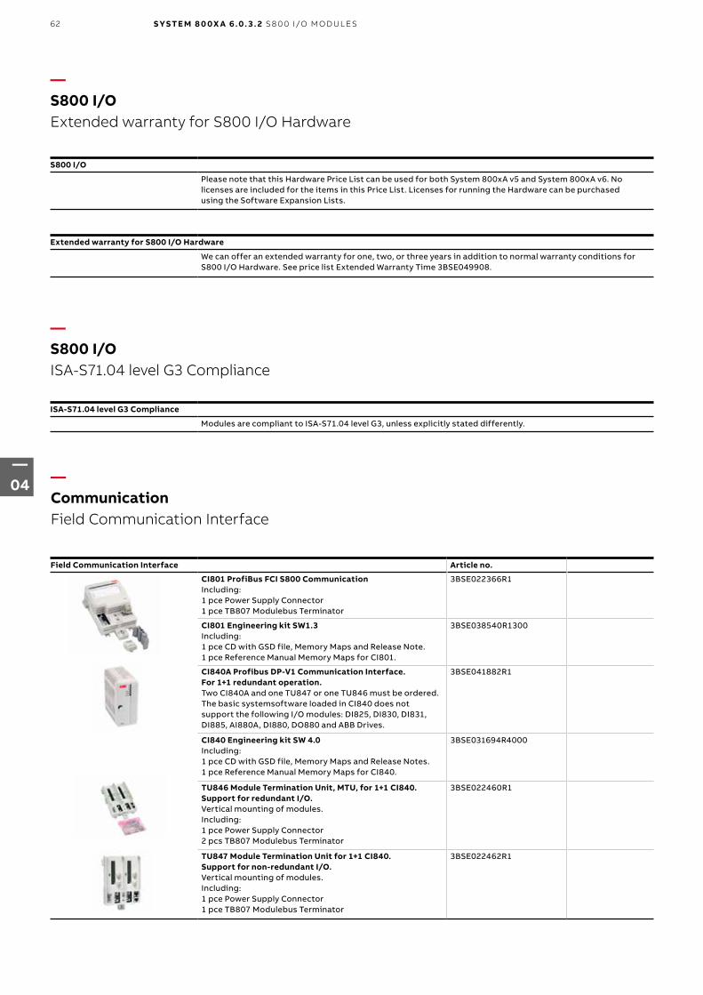
—CommunicationField Communication Interface
—S800 I/OExtended warranty for S800 I/O Hardware
—S800 I/OISA-S71.04 level G3 Compliance
Field Communication Interface Article no.
CI801 ProfiBus FCI S800 CommunicationIncluding:1 pce Power Supply Connector1 pce TB807 Modulebus Terminator
3BSE022366R1
CI801 Engineering kit SW1.3Including:1 pce CD with GSD file, Memory Maps and Release Note.1 pce Reference Manual Memory Maps for CI801.
3BSE038540R1300
CI840A Profibus DP-V1 Communication Interface. For 1+1 redundant operation.Two CI840A and one TU847 or one TU846 must be ordered.The basic systemsoftware loaded in CI840 does not support the following I/O modules: DI825, DI830, DI831, DI885, AI880A, DI880, DO880 and ABB Drives.
3BSE041882R1
CI840 Engineering kit SW 4.0Including:1 pce CD with GSD file, Memory Maps and Release Notes.1 pce Reference Manual Memory Maps for CI840.
3BSE031694R4000
TU846 Module Termination Unit, MTU, for 1+1 CI840. Support for redundant I/O.Vertical mounting of modules.Including:1 pce Power Supply Connector2 pcs TB807 Modulebus Terminator
3BSE022460R1
TU847 Module Termination Unit for 1+1 CI840. Support for non-redundant I/O.Vertical mounting of modules.Including:1 pce Power Supply Connector1 pce TB807 Modulebus Terminator
3BSE022462R1
S800 I/O
Please note that this Hardware Price List can be used for both System 800xA v5 and System 800xA v6. Nolicenses are included for the items in this Price List. Licenses for running the Hardware can be purchasedusing the Software Expansion Lists.
Extended warranty for S800 I/O Hardware
We can offer an extended warranty for one, two, or three years in addition to normal warranty conditions for S800 I/O Hardware. See price list Extended Warranty Time 3BSE049908.
ISA-S71.04 level G3 Compliance
Modules are compliant to ISA-S71.04 level G3, unless explicitly stated differently.
62
—04
S YS TE M 8 0 0X A 6 .0. 3 . 2 S 8 0 0 I/O M O D U L E S

Field Communication Interface Article no.
Extra, Front label set FCI/AC 70/TBSheet with 12 labels. For CI810, CI820, CI830, and TB820.
3BSC970089R1
Extra, Label set, item design. FCI/AC70/TBSheet with 40 labels. For CI810, CI820, CI830, and TB820.
3BSC970091R1
Mounting kitFor vertical mounting of CI801, CI840, and TB840 on a vertical DIN rail.
3BSE040749R1
Mounting profile 1800, 2 DIN rails and 1 cable duct.DIN rail length : 1650 mm + 210 mm (65”) + (8.3”).
3BSE049768R1
Al-profile with DIN Rail and Cable Duct, mounting 465 mm (19”).DIN rail length 429 mm (16,9”).
3BSE022255R1
Al-profile with DIN Rail and Cable Duct for RM550, mounting 592 mm (24”).DIN rail length 556 mm (21,9”).
3BSE022256R1
—CommunicationUpgrade Kit and Tool Cables
—CommunicationField Communication Interface
Upgrade Kit and Tool Cables Article no.
Upgrading of CI801, CI810, CI820, CI830, CI840 or CI840A to latest software version are available for download from ABB Library/Solutions Bank. Item R160 is cable connecting a PC to CI810, CI820 and CI830 for download of software. Item R165 is cable connecting a PC to CI840 or CI840A for download of software. CI801 requires items A160 and A165 for download of software.
TK527V030 Interface cableL = 3 m. DE9 pin to DE9 socket. For connection of CI810, CI820 and CI830 to PC.
3BSC950004R1
TK212A Tool cableRJ45 (male) to Dsub-9 (female), length 3 m. RJ45 8P8C plug (with shell). Cable : UL2464 26 AWG x 8C.
3BSC630197R1
FS801K01 Service adapter kitIncluding:1 pcs Service adapter FS8011 pcs cable TK802For connection of CI801 to PC. A cable TK212A is also needed.
3BSE038407R1
63
—04
S 8 0 0 I/O M O D U L E S S YS TE M 8 0 0X A 6 .0. 3 . 2

Analog Input Modules Article no.
AI810 Analog input 1x8 ch.0(4)..20mA, 0..10V, 12Bit, single ended, 0.1%, Rated isol. 50VUse Module Termination Unit TU810, TU812, TU814, TU818,TU830, TU833, TU835, TU838, TU850.
3BSE008516R1
AI815 Analog Input 1x8 ch with HART0(4)..20mA, 0(1)..5V, 12bit, single ended, 0.1%, Rated isol. 50V. Current limited transmitter power distribution.Use Module Termination Unit TU810, TU812, TU814, TU818,TU830, TU833, TU835, TU838.
3BSE052604R1
AI820 Analog input 4x1 ch.+-20mA, 0(4)...20mA, +-10V, +-5V, 0(1)...5V, diff., 50V CMV, 14bit+sign. Rin(curr)250 Ohms, Rated isol. 50V. Use Module Termination Unit TU810, TU812, TU814, TU830, TU833.
3BSE008544R1
AI825 Analog Input 4x1ch Galv. isol.-20..20mA, 0(4)..20mA, -10..10V, 0(2)..10V, Galvanically isolated channels 14Bit+sign, 0.1%, Rated isol. 250VUse Module Termination Unit TU811, TU813, TU831.
3BSE036456R1
AI830A Analog input 1x8ch RTDPt100, Ni100/120, Cu10, R, Rated isol. 50V. Use Module Termination Unit TU810, TU812, TU814, TU830, TU833.
3BSE040662R1
AI835A Analog input 8 ch. Thermocouple/mVRated isol. 50V. Use Module Termination Unit TU810, TU812, TU814, TU818, TU830, TU833.
3BSE051306R1
AI843 Analog Input, Redundant or Single 1x8ch Termocouple/mVRated isol. 50V. Use Modules Termination Unit TU818, TU830, TU833, TU842, TU843, TU852.
3BSE028925R1
AI845 Analog Input. Redundant or single 1x8ch. HART.0(4)..20mA, 0(1)..5V, 12bit, single ended, 0.1%, Rated isol. 50V.Current limited transmitter power distribution. Advanced on-board diagnostics. Use Module Termination Unit TU810, TU812, TU814, TU818, TU830, TU833, TU835, TU838, TU844, TU845, TU854.
3BSE023675R1
AI890 Analog Input 1x8 ch with Intrinsic Safety Interface0 (4)...20mA single ended 0,1%. Rated isol. 50VUse Module Termination Unit TU890 or TU891.
3BSC690071R1
AI893 Analog Input 8 ch. Temp. measuring. Intrinsic Safety Interf.For TC and RTD sensors. Rated isol. 50V.
3BSC690141R1
AI895 Analog Input 1x8 ch with Intrinsic Safety and HART.4...20mA single ended 0,1%. Rated isol. 50V.Use Module Termination Unit TU890 or TU891
3BSC690086R1
—S800 I/O S800 I/O Modules
64
—04
S YS TE M 8 0 0X A 6 .0. 3 . 2 S 8 0 0 I/O M O D U L E S

—S800 I/O S800 I/O Modules
Analog Output Modules Article no.
AO810V2 Analog Output 1x8 channels, 0(4)...20mA0(4)..20mA, 14bit RLmax 500/850 Ohms, Rated isolation 50V. Use module Termination Unit TU810, TU812, TU814, TU830 or TU833.
3BSE038415R1
AO815 Analog Output 1x8 ch with HART4..20mA, 12bit, 0.1%, RLmax 750 ohm, Rated isol. 50V.Use Module Termination Unit TU810, TU812, TU814, TU830 or TU833.
3BSE052605R1
AO820 Analog Output 4x1 ch,+-20mA, 0(4)...20mA, +-10V, 12bit+sign. Indiv. isol. ch. RL max 500 Ohms, Rated isol. 50V. Use Module Termination Unit TU810, TU812, TU814, TU830, TU833.
3BSE008546R1
AO845A Analog Output Redundant or single 1x8 ch HART4..20mA, 12bit, 0.1%, RLmax 750 ohm, Rated isol. 50V. Advanced on-board diagnostics. Use Module Termination Unit TU810, TU812, TU814, TU830, TU833, TU842, TU843, TU852.
3BSE045584R1
AO890 Analog Output 1x8 ch with Intrinsic Safety Interface0 (4)...20mA 0,1%. RL max 750 ohm Rated isol. 50VUse Module Termination Unit TU890 or TU891.
3BSC690072R1
AO895 Analog Output 1x8 ch with Intrinsic Safety and HART.4...20mA 0,1%. RL max 750 ohm Rated isol. 50V.Use Module Termination Unit TU890 or TU891.
3BSC690087R1
65
—04
S 8 0 0 I/O M O D U L E S S YS TE M 8 0 0X A 6 .0. 3 . 2

Digital Input Modules Article no.
DI810 Digital Input 24V d.c. 2x8 ch.Rated isolation 50V. Use Module Termination Unit TU810, TU812, TU814, TU830, TU833, TU838.
3BSE008508R1
DI811 2x8 ch 48V Digital input48Vd.c. 2x8 ch, Rated isol. 50V. Use Module Termination Unit TU810, TU812, TU814, TU818, TU830, TU833, TU838.
3BSE008552R1
DI814 Digital Input 24V d.c. Current Source 2x8 ch,Rated isol. 50V. Use Module Termination Unit TU810, TU812, TU814, TU830, TU833, TU838.
3BUR001454R1
DI818 Digital Input 24V d.c. 32 ch2x16 ch, Rated isol. 50V, Use Module Termination Unit TU818, TU819, TU830.Note: At pricebook release this item required a TSA to be ordered. Please, check current need of a TSA in the TSA Database before ordering.
3BSE069052R1
DI820 Digital Input 120V a.c./d.c.8x1 ch, Rated isol. 250V. Use Module Termination Unit TU811, TU813, TU831.
3BSE008512R1
DI821 Digital Input 230V a.c./d.c.8x1 ch, Rated isol. 250V. Use Module Termination Unit TU811, TU813, TU831.
3BSE008550R1
DI825 Digital Input 1x8ch, 125V d.c. SOEIndividually Isolated channels, Rated isol. 250V. Use Module Termination Unit TU811, TU813, TU831.
3BSE036373R1
DI828 Digital Input, 120V a.c./d.c. 16 ch16x1 ch, Rated isol. 250V, Use Module Termination Unit TU851.Note: At pricebook release this item required a TSA to be ordered. Please, check current need of a TSA in the TSA Database before ordering.
3BSE069054R1
DI830 Digital Input 24V d.c. SOE2x8 ch, Rated isol. 50V. Use Module Termination Unit TU810, TU812, TU814, TU818, TU830, TU833, TU838.
3BSE013210R1
DI831 Digital Input 48V d.c., SOE2x8 ch, Rated isol. 50V. Use Module Termination Unit TU810, TU812, TU814, TU830, TU833, TU838.
3BSE013212R1
DI840 Digital Input. Redundant or single, 24V d.c., 1x16 ch.Advanced On-Board diagnostics. Rated isol. 50V.Use Module Termination Unit TU810, TU812, TU814, TU818,TU830, TU833, TU838, TU842, TU843, TU852.
3BSE020836R1
DI885 Digital Input 24/48V d.c., SOE1x8 ch, Rated isol. 50VUse Module Termination Unit TU810, TU812, TU814, TU818,TU830, TU833.
3BSE013088R1
DI890 Digital Input 8x1 ch with Intrinsic Safety InterfaceRated isol. 50V. Use Module Termination Unit TU890 or TU891.
3BSC690073R1
—S800 I/O S800 I/O Modules
66
—04
S YS TE M 8 0 0X A 6 .0. 3 . 2 S 8 0 0 I/O M O D U L E S

—S800 I/OS800 I/O Modules
—S800 I/OPulse Counting Modules
Digital Output Modules Article no.
DO810 Digital Output 24 V d.c.2x8 ch 0.5A, Short circuit proof, Rated isol. 50V. Use Module Termination Unit TU810, TU812, TU814, TU830, TU833.
3BSE008510R1
DO814 Digital Output current sinking2x8 ch 0,5A , shortcut circuit proof, Rated isol.50VUse Module Termination Unit TU810, TU812, TU814, TU830,TU833, TU838.
3BUR001455R1
DO815 Digital Output 24V d.c2x4 ch, 2.0A short circuit proof. Rated isolation 50V. Use Module Termination Unit TU810, TU812, TU814, TU830, TU833.
3BSE013258R1
DO818 Digital Output 24V d.c. 32 ch2x16 ch, 0.5A, Short circuit proof, Rated isol. 50V,Use Module Termination Unit TU818, TU819, TU830.
3BSE069053R1
DO820 Digital Output, Relay. Normal open8x1 ch, 24-230V a.c../d.c. 3A, cos phi>0.4, d.c. 42W, Rated isol. 250V. Use Module Termination Unit TU811, TU813, TU831, TU836, TU837, TU851.
3BSE008514R1
DO821 Digital Output, Relay. Normal closed8x1 ch, 24-230V a.c./d.c.. 3A, cos phi>0.4, d.c. 42W, Ratedisol.250V. Use Module Termination Unit TU811, TU813, TU831, TU836, TU837, TU851.
3BSE013250R1
DO828 Digital Output, Relay Normally Open, 16 ch16x1 ch, 5-250V a.c and 5-125V d.c, max 2A, Rated isol. 250V, Use Module Termination Unit TU851.
3BSE069055R1
DO840 Digital Output. Redundant or single.24V d.c., 0.5A. 2x8 ch. Advanced On-board diagnostics. Rated isol. 50V. Use Module Termination Unit TU810, TU812, TU814, TU830, TU833, TU842, TU843, TU852.
3BSE020838R1
DO890 Digital Output 4x1 ch with Intrinsic Safety InterfaceRated isol. 50V. Use Module Termination Unit TU890 or TU891.
3BSC690074R1
Pulse Counting Modules Article no.
DP820 Pulse Counter RS-422, Current, 5V, (12V), 24V2 ch bidirectional pulse counters and frequency measurement.1,5MHz Rated isol 50V. Use Module Termination Unit TU810, TU812, TU814, TU830, TU833.
3BSE013228R1
DP840 Pulse Counter or Frequency Measurement Module.Redundant or single.DP840 Pulse Counter Module. Redundant or single. 1x8 ch,20kHz. Rated isol. 50VUse Module Termination Unit TU810, TU812, TU814, TU818, TU830, TU833, TU842, TU843, TU844, TU845, TU852, TU854.
3BSE028926R1
67
—04
S 8 0 0 I/O M O D U L E S S YS TE M 8 0 0X A 6 .0. 3 . 2

—S800 I/OLabel sets for I/O Modules
—S800 I/OHigh Integrity I/O Modules
Label sets for I/O Modules Article no.
Transparent film fronts1Set of 12 transparent plastic film fronts.To be used with ordinary paper quality.
3BSE072159R1
White colored plastic coated paperOne sheet of size A4. Original paper quality. No need to use transparent films.
3BSE072160R1
Yellow colored plastic coated paperOne sheet of size A4. Original paper quality. No need to use transparent films. To be used with DI880, DO880, AI880A.
3BSE072161R1
High Integrity I/O Modules Article no.
The modules can only be connected to AC 800M controller PM858, PM862, PM866A, PM865, PM867 and PM891. Direct connection to the modulebus and via the optical modulebus via TB840 (not TB820).
AI880A High Integrity Analog Input. Single or Redundant. HART4..20mA, 8 ch. Current input. HART communication. Certified for SIL3. Requires configuration according to Safety Manual.Use Module Termination Unit TU834, TU844, TU845, TU854.
3BSE039293R1
DI880 High Integrity Digital Input Single or Redundant24V d.c., 16 ch. 24V d.c. inputs. Certified for SIL3. Requiresconfiguration according to Safety Manual.Use Module Termination Unit TU810, TU812, TU814, TU818,TU830, TU833, TU838, TU842, TU843, TU852.
3BSE028586R1
DO880 High Integrity Digital Output. Single or Redundant.24V d.c., 16 ch. 0,5A Outputs. Certified for SIL3. Requiresconfiguration according to Safety Manual. Use Module Termination Unit TU810, TU812, TU814,TU830, TU833, TU842, TU843, TU852.
3BSE028602R1
SS823 Voting Device, G3 CompliantRequired in a High Integrity 800xA system.One per power supply unit, also at redundent configurations.
3BSE038226R1
68
—04
S YS TE M 8 0 0X A 6 .0. 3 . 2 S 8 0 0 I/O M O D U L E S

—S800 I/OModule Termination Units
Module Termination Units Article no.
TU805K01 Termination Units for two or three wire connection of DI801 and DO801Include 10 pcs of Termination Unit TU805.
3BSE035990R1
TU810V1 Compact Module Termination Unit, MTU, 50V.2x8 signal terminals, rated isol. 50V.
3BSE013230R1
TU811V1 Compact Module Termination Unit, MTU, 250V.1x8 signal terminals, rated isol. 250V.
3BSE013231R1
TU812V1 Compact Module Termination Unit, MTU, 50V.With 25 pin D-sub connector, rated isol. 50V. D-sub (female)connector is not enclosed.
3BSE013232R1
TU813 Compact Module Termination Unit, MTU, 250V2x8 Signal terminals, Rated isol. 250V Detachable (pluggable) connectors are enclosed.
3BSE036714R1
TU814V1 Compact Module Termination Unit, MTU, 50V.2x8 Signal terminals, rated isol. 50V. Detachable (pluggable) connectors are enclosed.
3BSE013233R1
TU818 Compact Module Termination Unit, MTU, 50V1x32 (and 2x16) signal terminals, Rated isol. 50V
3BSE069209R1
TU819 Compact Module Termination Unit, MTU, 50V.With 2x25 pin D-sub connector, Rated isol. 50V, D-sub (female) connector is not enclosed.
3BSE068891R1
TU830V1 Extended Module Termination Unit, MTU, 50V.2x16 signal terminals, rated isol. 50V.
3BSE013234R1
TU831V1 Extended Module Termination Unit, MTU, 250V.2x8 signal terminals, rated isol. 250V.
3BSE013235R1
TU833 Extended Module Termination Unit, MTU, 50V.2x16 signal terminals, Rated isol. 50V. Spring-cage terminals.
3BSE038726R1
TU835V1 Extended Module Termination Unit, MTU, 50V.8 fused power outlets, 8 signal terminals, rated isol. 50V.
3BSE013236R1
TU836V1 Extended Module Termination Unit, MTU, 250V.2x4 fused signals, 2x4 return terminals, 2x2 L 2x2N terminals, rated isol. 250V.
3BSE013237R1
TU837V1 Extended Module Termination Unit, MTU, 250V.8x1 fused isol. signals, 8x1 L terminals, 2x6 N terminals,rated isol. 250V.
3BSE013238R1
TU838 Extended Module Termination Unit, MTU, 50V.2x4 fused transducer power outlets, 16 signal terminals, 2x4 return terminals, 2x2 L+, 2x2 L- terminals, rated isol. 50V. Module is mounted horizontally.
3BSE008572R1
TU839 Extended Module Termination Unit, 250V2x8 signal terminals. 2x4 fused sensor power. Rated isol. 250V
3BSE046966R1
TU842 Module Termination Unit, MTU, for redundant applications, 50V.Used for AO845, DI840, DO840. Horizontal mounted DIN rail. Rated isol. 50V.
3BSE020850R1
TU843 Module Termination Unit, MTU, for redundant applications, 50V.Used for AO845, DI840, DO840. Vertical mounted DIN rail. Rated isol. 50V.
3BSE021443R1
69
—04
S 8 0 0 I/O M O D U L E S S YS TE M 8 0 0X A 6 .0. 3 . 2

—S800 I/O and S800L I/OModule Termination Units
Module Termination Units Article no.
TU844 Module Termination Unit, MTU, for redundant applications, 50V.Used with AI845, AI880 and DP840. Horizontal mounted DIN rail. Rated isol. 50V. Shunt Stick not included.
3BSE021445R1
TU845 Module Termination Unit, MTU, for redundant applications, 50V.Used with AI845, AI880A and DP840. Vertical mounted DIN rail. Rated isol. 50V. Shunt Stick not included.
3BSE021447R1
TU850 Extended Module Termination Unit, MTU, 50V2x8 signal terminals and 2x8 disconnetable current limitedsensor/transmitter outlet power terminals. Rated isol. 50V.
3BSE050930R1
TU851 Extended Module Termination Unit, MTU, 250V2x16 signal terminals, Rated isol. 250V
3BSE068782R1
TU852 Module Termination Unit, MTU, for redundant applications, 50VHorizontal mounted DIN rail, used with redundnat AO, DI, DO and DP I/O modules, with 2x25 pin D-sub connector, Rated isol. 50V
3BSE069964R1
TU854 Module Termination Unit, MTU, for redundant applications, 50VHorizontal mounted DIN rail, used with redundnat AI and DP I/O modules, with 1x25 pin D-sub connector, Rated isol. 50V, Shunt Stick not included.
3BSE069966R1
TU890 Module Termination Unit for Intrinsic Safety applicationsIntrinsic Safety Interface, 3x9 signal terminals Rated isol. 50V
3BSC690075R1
TU891 Module Termination Unit for non Intrinsic Safetyapplications3x9 signal terminals Rated isol. 50V.
3BSC840157R1
TY801K01 8pcs Shunt Stick TY801125 + 125 ohms shunt. Used for AI845 and AI880A on TU844, TU845, TU854.
3BSE023607R1
TY804K01 8pcs Shunt Stick TY8041000 ohms shunt. Used for DP840 on TU844, TU845, TU854
3BSE033670R1
TY805K01 8pcs Shunt Stick TY805125 + 125 ohms shunt with current limitation on transmitter power. Used for AI845 and AI880A on TU834, TU844, TU845, TU854.
3BSE081160R1
TY820K01 10pcs Temperature Sensor TY820TY820 is a temperature sensor with a PT 100 element. Can be used with AI835/AI835A and AI843 to measure cold junction Temperature.
3BSE056980R1
70
—04
S YS TE M 8 0 0X A 6 .0. 3 . 2 S 8 0 0 I/O M O D U L E S

—S800L I/OS800L I/O Modules
Analog Input Modules Article no.
AI801 Analog input 1x8 ch,0(4)..20mA, 12bit, single ended, 0.1%, Rated isol. 50V.
3BSE020512R1
Analog Output Modules Article no.
AO801 Analog output 1x8 ch,0(4)...20mA, 12 bit, RLmax 850 Ohm, Rated isol. 50V.
3BSE020514R1
Digital Input Modules Article no.
DI801 Digital Input 24V d.c.1x16 ch, Rated isol.50V
3BSE020508R1
DI802 Digital Input 120V a.c./d.c., 8x1ch.Rated isol. 250V.
3BSE022360R1
DI803 Digital Input 230V a.c./d.c., 8x1ch.Rated isol. 250V.
3BSE022362R1
Digital Output Modules Article no.
DO801 Digital Output 16ch. 24V d.c. 0.5A.Short circuit proof, Rated isol. 50V
3BSE020510R1
DO802 Digital Output, Relay. Normal open8x1 ch, 24-230V, a.c./d.c. Rated isol. 250V
3BSE022364R1
Label sets for S800L I/O Modules Article no.
Label Set S800L, 16chSheet with 12 labels for 16 channels I/O modules.
3BSE019419R1
Label Set S800L, 8chText colour: Black, Text style: Helv. reg., Text height: 2 mm,Material: Polyesterfilm Xeroperm t = 0,12Sheet with 12 labels for 8 channels I/O modules
3BSE019419R2
—S800L I/OLabel sets for S800L I/O Modules
71
—04
S 8 0 0 I/O M O D U L E S S YS TE M 8 0 0X A 6 .0. 3 . 2

—S800 I/O and S800L I/OModuleBus Communication Parts
ModuleBus Communication Parts Article no.
TB805 Bus OutletModulebus extension cable adaptor D-sub 25, female.One requried per extension cable TK801.
3BSE008534R1
TB845, Dual Modulebus outletModulebus extension cable adaptor two D-sub, female.Two TK801 cables for redundancy.
3BSE021437R1
TB806 Bus InletModulebus extension cable adaptor D-sub 25, male.One requried per extension cable TK801.
3BSE008536R1
TB846, Dual Modulebus inletModulebus extension cable adaptor two D-sub, male.Two TK801 cables for redundancy.
3BSE021439R1
TK801V003 CableModulebus Extension Shielded Cable 0.3m D-sub 25, male-female.
3BSC950089R1
TK801V006 CableModulebus Extension Shielded Cable 0.6m D-sub 25, male-female.
3BSC950089R2
TK801V012 CableModulebus Extension Shielded Cable 1.2m D-sub 25, male-female.
3BSC950089R3
TB807 Modulebus terminator 3BSE008538R1
TB820V2 Modulebus Cluster ModemOptical cluster modem for non redundant operation.Including:1 pce Power Supply Connector1 pce TB807 Modulebus Terminator
3BSE013208R1
TB825 Optical Media Converter Multi ModeShort to long distance optical fiber conversion.For modulebus communication up to 1000 m.
3BSE036634R1
TB826 Optical Media Converter Single ModeShort to long distance optical fiber conversion. For modulebus communication up to 5000 m, for S800 I/O HI up to 20000 m.
3BSE061637R1
TB840A Modulebus Cluster ModemOptical cluster modem for 1+1 redundant operation.Optiskt cluster-modem for 1+1 redundans.Optisches Cluster-Modem for 1+1 redundanten Betrieb
3BSE037760R1
TB842 Modulebus Optical PortUsed together with CI801 and CI840, connected via TB806 or TB846. 10 Mbits driver.
3BSE022464R1
TU807 Termination Unit for TB840/TB840ASupport for single modulebus I/O. Including: 1 pcs TB807
3BSE039025R1
TU840 Termination Unit for 1+1 TB840. Support for redundant I/OIncluding:1 pce Power Supply Connector2 pcs TB807 Modulebus Terminator
3BSE020846R1
TU841 Termination unit for 1+1 TB840. Support for non-redundant I/O.Including:1 pce Power Supply Connector1 pce TB807 Modulebus Terminator
3BSE020848R1
72
—04
S YS TE M 8 0 0X A 6 .0. 3 . 2 S 8 0 0 I/O M O D U L E S

—S800 I/O and S800L I/OModuleBus Communication Parts
ModuleBus Communication Parts Article no.
TU848, MTU with individual power supply for red. TB840/TB840A. Support for dual modulebus.Including:2 pcs TB807
3BSE042558R1
TU849, MTU with individual power supply for red. TB840/TB840A. Support for single modulebusIncluding:1 pcs TB807
3BSE042560R1
TK811V015 POF Cable, 1.5m, DuplexL = 1.5 m latching duplex connector Duplex plastic fibre
3BSC950107R1
TK811V050 POF Cable, 5m, DuplexL = 5 m latching duplex connector Duplex plastic fibre
3BSC950107R2
TK811V150 POF Cable, 15m, DuplexL = 15 m latching duplex connector Duplex plastic fibre
3BSC950107R3
TK812V015 POF Cable, 1.5m, SimplexL = 1.5 m latching connector Simplex plastic fibre
3BSC950118R1
TK812V050 POF Cable, 5m, SimplexL = 5.0 m latching connector Simplex plastic fibre
3BSC950118R2
TK812V150 POF Cable, 15m, SimplexL = 15 m latching connector Simplex plastic fibre
3BSC950118R3
—S800 I/O Power supply and selection guide
Feature SD822Z SD831 SD832 SD833 SD834 SS822Z SS832 SS823
Rated output current 5 A 3 A 5 A 10 A 20 A 20 A 10 A (20 A in parallell operation)
20 A
Rated output power 120 W 72 W 120 W 240 W 480 W - - -
Rated output voltage d.c. 24 V d.c. 24 V d.c. 24 V d.c. 24 V d.c. 24 V - - -
Rated input power 280 VA 135 W 134/143 VA 240/283 VA 447/514 VA 547/568 VA 500 W 240 W (480 W in parallell operation)
500 W
Mains/input voltage, nominal
115/230 V a.c.
225-250 V d.c.
100-240 V a.c.
110-300 V d.c.
100-120 V a.c.200-240 V a.c.Auto-select input
100-120 V a.c.200-240 V a.c.Auto-select input
100-240 V a.c.
110-150 V d.c
2x24 V d.c. 2x24 V d.c(1x24 V d.c in parallell operation)
1x24 V d.c
Mains voltage variation allowed
85 - 110% 90-264 V a.c.88-375 V d.c.
90-132 V a.c.180-264 V a.c.
90-132 V a.c.180-264 V a.c.
85-276 V a.c.88-375 V d.c.
- - -
Mains/input voltage, max. (a.c.= 45-65 Hz)
138/275 V a.c.375 V d.c.
264-300 V a.c.
264-300 V a.c.
264-300 V a.c.
264-300 V a.c.
60 V d.c. 60 V d.c. 60 V d.c.
Primary peak inrush current at power on
Typ 15 A <28/<54 A <10 A <10 A <13 A - - -
Applications SELV and PELV
SELV and PELV
SELV and PELV
SELV and PELV
SELV and PELV
- - -
Load sharing Two in parallell
- - - Parallell connection
Two in parallell
Two in parallell
Yes
Power Factor (at rated output power)
0.61/0.56 0.56/0.47 0.59/0.51 0.95/0.90 - - -
Heat dissipation 13.3 W 10/8 W 14/13 W 24/22 W 40/32 W 10 W at 20 A and 2,5 W at 5 A
9 W (18 W) 24 W at 20 A and 6 W at 5 A
Efficiency factor 88 % 88/89.8 % 89.4/90.2 % 91/91.6 % 92.4/93.9 % - - -
73
—04
S 8 0 0 I/O M O D U L E S S YS TE M 8 0 0X A 6 .0. 3 . 2

—S800I/O Power supply and selection guide
Feature SD822Z SD831 SD832 SD833 SD834 SS822Z SS832 SS823
Output voltage regulation at max. current
+- 2% < 50 mV / < 100 mV
< 70 mV / < 100 mV s
< 70 mV / < 100 mV
< 10 mV / < 100 mV
0,5 V lower than input
0.85 V lower than input
1.2 V lower than input
Ripple (peak to peak) < 50 mV < 50 mV < 50 mV < 50 mV < 100 mV - - -
Secondary voltage holdup time at mains blackout
> 20 ms 29/120 ms 80/78 ms 46/47 ms 32/51 ms - - -
Maximum output current (min)
10 A 3.3 A 6 A At ambient temp < 45 °C
12 A At ambient temp < 45 °C
30 A < 4 s 35 A (Overload)
25 A (Overload)
35 A (Overload)
Maximum ambient temperature
60 °C 60 °C 60 °C 60 °C 60 °C 60 °C 60 °C 55 °C
Primary: Recommended external fuse (1)
10 A 10-20 A 10-20 A 10-20 A 10-20 A - - -
Secondary: Short circuit
< 10 A < 8 A < 14 A < 18 A < 40 A - - -
Secondary: Over-Voltage protection
29 V < 39 V < 39 V < 39 V < 37 V - - < 30 V
Class of protection I PE (Protective Earth) connection required - - -
Protection rating IP20 according to IEC60529
Width 65 mm (2.56”)
32 mm (1.26”) 32 mm (1.26”) 60 mm (2.36”)
82 mm (3.23”) 50 mm (1.97”) 32 mm (1.26”) 116 mm (4.6”)
Depth 110 mm (4.3”)
102 mm (4.02”)
117 mm (4.61”)
117 mm (4.61”)
127 mm (5.0”)
110 mm (4.3”)
117 mm (4.61”)
145 mm (5.8”) including connector
Height 125 mm (4.9”)
124 mm (4.88”)
124 mm (4.88”)
124 mm (4.88”)
124 mm (4.88”)
125 mm (4.9”)
125 mm (4.9”)
132 mm (5.3”)
Mounting spacing Width mm
15 mm (0.59”) 15 mm (0.59”) 15 mm (0.59”) 15 mm (0.59”) 15 mm (0.59”) 15 mm (0.59”) 15 mm (0.59”) 15 mm (0.6”)
Mounting spacing Height mm
25 mm (1”) 40 mm (1.57”) 40 mm (1.57”) 40 mm (1.57”) 40 mm (1.57”) 25 mm (1”) 25 mm (1”) 25 mm (1.2”)
Weight (lbs.) 620 g (1.4 lbs)
430 g (0.9 lbs.)
500 g (1.1 lbs.)
700 g (1.5 lbs.)
1200 g (2.6 lbs.)
630 g (1.4 lbs)
350 g (0.77 lbs.)
870 g (1.9 Ibs.)
Corrosive atmosphere ISA-S71.04
G3 G2 G2 G2 G2 G3 G2 G3
CE mark Yes Yes Yes Yes Yes Yes Yes Yes
El. safety, Haz loc, C1 Zone 2
No No No No No No No No
El. safety, Haz loc, C1 Div 2
No No No No Yes No No No
Electrical safety IEC 61131-2, UL 508, EN 50178 (Note! UL 508 not valid for SS823)
Pollution degree Degree 2, IEC 60664-1
Mechanical operating conditions
EN 61131-2
EMC EN 61000-6-4 and EN 61000-6-2
Overvoltage Categories
Over-voltage Category III (IEC/EN 60664-1)
(1) Microcircuit Breaker (MCB), Characteristic B
74
—04
S YS TE M 8 0 0X A 6 .0. 3 . 2 S 8 0 0 I/O M O D U L E S

—S800 I/OPower Supply
Power Supply Article no.
SD822Z Power Supply Device, G3 CompliantInput 115/230V a.c. switch selectable, output 24V d.c., 5A.If redundant power application is required connect to SS822Z Voting Unit. Width = 65 mm. DIN rail mounted.
3BSC610054R1
SS822Z Power Voting Unit, G3 CompliantWith dual 24V d.c 20A inputs, single 24V d.c. 20A output. Each power input supervised. Used if redundant power supply is required. For use with power supply SD822Z.Width = 50 mm. DIN rail mounted.
3BSC610055R1
SD831 Power Supply Device, G2 CompliantInput a.c. 100-240 V or d.c. 110-300 V. Output d.c. 24 V 3A. If redundant power application is required connect toSS8XX. Voting unit. Width = 35mm. DIN rail mounted.
3BSC610064R1
SD832 Power Supply Device, G2 CompliantInput a.c. 100-120/200-240 V. Output d.c. 24 V 5A, auto-select input. If redundant power application is required connect to SD8XX. Voting unit. Width = 35mm. DIN rail mounted.
3BSC610065R1
SD833 Power Supply Device, G2 CompliantInput a.c. 100-120/200-240 V, auto-select input. Output d.c. 24 V 10A. If redundant power application is required connect to SD8XX. Voting unit. Width = 60mm. DIN rail mounted.
3BSC610066R1
SD834 Power Supply Device, G2 CompliantInput a.c. 100-240 V or d.c. 110-150 V. Output d.c. 24 V 20A. If redundant power application is required connect to SS8XX. Voting unit. Width = 85mm. DIN rail mounted.
3BSC610067R1
SS832 Voting Device, G2 CompliantInput d.c. 24 V. Dual 24 V to single 24 V, 2x10A.Width = 35mm. DIN rail mounted.
3BSC610068R1
Mains Breaker Kit for DIN Rail115/230V a.c. with input terminals, breaker and 3 fused (6.3A), double output terminals. Width = 102,5 mm.
3BSE022262R1
75
—04
S 8 0 0 I/O M O D U L E S S YS TE M 8 0 0X A 6 .0. 3 . 2

—Process Industries Application Libraries
—Process Industries Application LibrariesProcess Control Device Library
Process Industries Application Libraries
The Process Industries Application Libraries (PIAL) in this book include Process Control Device Library (PCDL), Process Control Equipment Library (PCEL) and ProBase Library. One valid license is required per 800xA system. User documentation is provided electronically with the product media. The licenses support use with System 800xA. These licenses entitle license holders to use the library in one system, meaning one Aspect Server. Please refer to System Guide Ordering and Licensing (3BSE041435) for more information.
PIAL Media
Media for this product can be downloaded from ABB Library and MyABB/MyControlSystem.
Process Control Device Library
The 800xA PC Device Library provides device-level objects. The PCDeviceLib is a customized library for the process industry. It builds upon the 800xA - AC800M library to provide additional functionality and engineering efficiency. Benefits include minimizing the initial learning curve for the Industrial IT Extended Automation System 800xA and to minimize the engineering effort.
The PCDevice Library contains an extensive list of objects, but it is licensed only by the number of Control Elements used. Control Elements are the Valves, Motors and PID Loops in a system.
The following PCDevice library control modules are categorized as Control Elements – Valve, ValveMan, MotorOnOff, MotorOnOffAdv, Motor2Speed, MotorVarSpeed, ControllerPIDLoop, ControlValvePneumatic, ControlValveElectric, ChokeValve, MotorOnOffCore, Motor2SpeedCore and MotorVarSpeedCore.
76
—04
S YS TE M 8 0 0X A 6 .0. 3 . 2 S 8 0 0 I/O M O D U L E S

—Process Industries Application Libraries
Process Control Device Library Licenses Article no.
Base Process Control Device Library (including 125 ControlElements)The PCDevice Library comes with all PCDevice library objects but only the 13 objects listed above are counted as Control Elements. To arrive at the correct number of Control Elements to purchase, count the number of Valve, Motor and ControllerPIDLoop objects associated with the project.
3BSE081553R1
Additional Control Device Library Licenses Article no.
Additional 125 Control ElementsAdditional 125 Control ElementsAdditional 125 ControlElement
3BSE081554R1
PCDL Application Engineering Article no.
PCDL License for Application EngineeringThis Engineering system License is intended to use forApplication Engineering purpose only. A maximum of 2500Control Elements will be issued as a part of the license. Forproduction system, appropriate quantity of Control Elements license must be purchased separately.Media is ordered separately.
3BSE081555R1
PCDL Additional License for Application EngineeringEach additional license comes with 2500 control elementslicense.
3BSE081556R1
77
—04
S 8 0 0 I/O M O D U L E S S YS TE M 8 0 0X A 6 .0. 3 . 2

—Process Industries Application LibrariesProcess Control Equipment Library
Process Control Equipment Library
Process Control Equipment Library (PCEquipmentLib) is a comprehensive library of Equipment Module templates, and toolkit components for industrial IT Extended Automation System 800xA.
PCEquipmentLib is designed to optimize the specification and building of ANSI/ISA-88.01-1995 style Equipment Modules and customized Process Units. Designed to "plug and produce" with standard PCDeviceLib control objects, PCEquipmentLib shares common terminology, engineering principles, and naming conventions to make engineering consistent and easy. It is a requirement to use a compatible version of PCDevice Library in conjunction with PCEquipment Library. Refer to PCEquipment Library release notes for appropriate version information.
The PCEquipment Library contains an extensive list of pre-engineered and validated objects like Unit template and Standard Phases, equipment modules, Quality Monitor, pcc supervision, EqTimer, Prompts/PromptsAlarmOwner etc. The PCEquipment Library also contains pre-engineered facility automation Solution objects.
Process Control Equipment Library Licenses Article no.
Base Process Control Equipment Library with ProductionManagementThis license is for working with up to 125 PCDevice LibControl Elements.
This license shall allow using any number of PCEL BatchUnit type with Standard Phases. All other modules forEquipment module implementation, quality monitoring, PCC configuration, and operator visualization are included with this license. This license also includes Pre-engineered Facility Automation Solutions like AHUs, Scheduler, ZoneMonitor, Facility, Start-Stop sequence, Operator visualization etc.
With one base license, a maximum of 125 PCDeviceLibControl Elements can be used. An incremental purchase ofPCDevice Lib Control Elements (License Expansion)requires an incremental purchase of PCEquipment Liblicense (License Expansion).
Note: License for PCDevice Lib Control Elements to bepurchased separately.
3BSE081558R1
78
—04
S YS TE M 8 0 0X A 6 .0. 3 . 2 S 8 0 0 I/O M O D U L E S

Additional Control Equipment Library Licenses
It is a requirement to use a compatible version of PCDevice Library in conjunction with PCEquipment Library. Refer to PCEquipment Library release notes for appropriate version information. Additional expansion licenses can be purchased. When ordering additional licenses, the original quantity and the license information must be included with the expansion order.
—Process Industries Application LibrariesProcess Control Equipment Library Licenses
Process Control Equipment Library Licenses Article no.
Base Process Control Equipment Library without Production ManagementThis license is for working with up to 125 PCDevice LibControl Elements. This license shall allow using any number of PCEL Equipment Module (EM) types with Device Summary and ModeControl. Other modules like Prompt, PromptAlarmOwner and EqTimer are included in the license.This license also includes Pre-engineered FacilityAutomation Solution objects like AHUs, Scheduler, ZoneMonitor, Facility Start-Stop sequence, Operator visualization etc.
With one base license, a maximum of 125 PCDL ControlElements can be used. An incremental purchase ofPCDevice Lib Control Elements(License Expansion)requires an incremental purchase of PCEquipment Liblicense (License Expansion).
Note: License for PCDevice Lib Control Elements to bepurchased separately.
3BSE081559R1
Additional Control Equipment Library Licenses Article no.
Additional Process Control Equipment Library With Production Management Each Expansion license is for working with up to 125 PCDevice Lib Control Elements.
3BSE081560R1
Additional Process Control Equipment Library Without Production Management Each Expansion license is for working with up to 125 PCDevice Lib Control Elements.
3BSE081561R1
79
—04
S 8 0 0 I/O M O D U L E S S YS TE M 8 0 0X A 6 .0. 3 . 2

—Process Industries Application LibrariesPCEL Application Engineering
PCEL Application Engineering Article no.
PCEL License for Application EngineeringThis Engineering system License is intended to use forApplication Engineering purpose only. A maximum of 20'PCEL With Production Management'. License quantity willbe issued as a part of this license, which can be used withboth Batch and Non-Batch version of PCEquipmentLib. For production system, appropriate quantity of PCEL With Production Management or WithOut Production Management license quantities must be purchased separately. Media is ordered separately.
3BSE081562R1
PCEL Additional License for Application EngineeringEach additional license comes with 20 PCEL WithBatch license.
3BSE081557R1
ProBase Licenses Article no.
ProBase licensing is based on type and number of controllers executing ProBase.
ProBase 6.0 Operator Workplace - First Client 3BSE081563R1
ProBase 6.0 Operator Workplace - Additional Client 3BSE081564R1
ProBase 6.0 PM861/PM861A Software License 3BSE081565R1
ProBase 6.0 PM864/PM864A Software License 3BSE081566R1
ProBase 6.0 PM865 Software License 3BSE081567R1
ProBase 6.0 PM866 Software License 3BSE081568R1
ProBase 6.0 PM891 Software License 3BSE081569R1
ProBase 6.0 Demo License and Application Engineering LicenseThis license is to be used with the 800xA Demo License andApplication Engineering License. The intended use is sales related activities such as fairs, training centers etc that requires a full sized system. It is also intended for application engineering. Media is ordered separately.
3BSE081570R1
—Process Industries Application LibrariesProBase
ProBase
ProBase is a set of System 800xA libraries with industry specific functionality targeting liquid process handling or other applications where routing, storage of material, CIP, etc. are a major concern in the application. Example industries are food & beverage, chemical, pharmaceuticals, tank farms, etc.
80
—04
S YS TE M 8 0 0X A 6 .0. 3 . 2 S 8 0 0 I/O M O D U L E S

The S900 remote I/O system communicates with System 800xA or other controllers over PROFIBUS. Suitable for applications in the che-mical, pharmaceutical, oil and gas industries, S900 I/O can be installed in hazardous areas, thereby reducing marshalling and wiring costs.
Further maintenance savings can be achieved through S900’s extended diagnostics and the use of HART®-compliant field devices.
Three series of S900 I/O are available:• S-series for applications in Zone 1 hazardous
areas• B-series for applications in Zone 2 hazardous
areas• N-series for applications in non hazardous
areas
Additional solutions for specific applications are available:• Field housing - for wall mounting and field
mounting in Zone 1 installations with system approval fully certified in accordance with ATEX. The high-grade steel housing is prepared for wall-mounting with facility for insulated screen rails or terminals.
The S900 components are based on a passive backplane suitable for mounting on a DIN rail or directly in a sub-distribution board. The passive backplane includes internal bus communication,
terminals for field circuits, communication, and power supply. The function modules are plugged into the backplane in their appropriate slots. The redundant backplane has two slots for power supply units, two slots for communication inter-faces, and 16 slots for function modules.
Digital function modules have up to 8 channels, analog modules up to four. Therefore, when using a redundant backplane, 128 digital or 64 analog channels can be connected per station. In the case of the S and B series, up to ten S900 stations can be connected on a single fieldbus line.
Key S900 benefits include:• Intrinsically safe - can be installed in Zone 1 and
Zone 2 areas.• Good price/performance ratio because external
barriers have been removed and costs are reduced in terms of cabling, installation, hard-ware, and maintenance.
• Easy configuration using either FDT/DTM or GSD files, allowing easy integration with System 800xA process control systems.
• High availability of the plant thanks to redun-dancy and hot-swap capability of all compo-nents during operation.
—S900 Remote I/O System
—TU921N for S900 I/O
Series Assembly Field devices / signals
Hazardous area approval
S series In Zone 1 In Zones 2, 1 and 0 (intrinsically safe signals)
ATEX Zone 1 (Blue TU921S)
B series In Zone 2 In Zones 2, 1 and 0 (intrinsically safe signals)
ATEX Zone 2 (Blue TU921B)
N series In safe areas In safe areas No (Black TU921N)
81
—05
S9 0 0 R EM OTE I/O S Y S TEM S YS TE M 8 0 0X A 6 .0. 3 . 2

NA
MU
R in
put
s
Bin
ary
24 V
Bin
ary
48
V
Bin
ary
110
V
Bin
ary
230
V
Bin
ary
Rel
ay
Ana
log
Uni
po
lar
Ana
log
Bip
ola
r
Tem
per
atur
e R
TD
Tem
per
atur
e T/
C
SOE
HA
RT
Intr
insi
c sa
fety
Red
und
ant
Hig
h in
teg
rity
I/O Features S900Digital I/O modulesDX910S,B,N* S,BDigital output modulesDO910S,B,N* S,BDO930NPulse input modulesDP910S,B,N* S,BAnalog input modulesAI910S,B,N* S,BAI930S,B,N* S,BAI931S,B,N* S,BAI950S,B,N* S,BAnalog output modulesAO910S,B,N* S,BAO920S,B,N* S,BAO930S,B,N* S,B*
—S900 Remote I/O SystemEx zone 1 system components
Termination Unit Article no.
TU921S Redundant Termination Unit (TU16R-Ex)for 16 I/O-modulesredundant communication and power(Delivery includes CD910)
3KDE175111L9210
Power Supply Article no.
SA920S Power Supplyfor 24 V DCDo not mix SA910S with SA920S for redundancy (observe Release Notes)
3BDH000602R1
Communication Interface Article no.
CI920AS Communication Interface V 2.1 (CIPBA-Ex)Use only CI920AS with the same firmware for redundancy for PROFIBUS DP-V1 (observe Release Notes).
3BDH000690R1
For details about S900 I/O please refer to the S900 catalog, document number 3BDD010420.
82
—05
S YS TE M 8 0 0X A 6 .0. 3 . 2 S9 0 0 R EM OTE I/O S Y S TEM

—S900 Remote I/O SystemEx zone 1 system components
Digital Input or Output Article no.
DX910S Digital Input or Output (DIO8-Ex)input for dry contact or NAMUR initiatoroutput for low power Intrinsic Safe valves
3KDE175311L9100
DO910S Digital Output (DO4-Ex)output for Intrinsic Safe valves
3KDE175321L9100
DP910S Frequency Input (FI2-Ex)input for dry contact or NAMUR initiator
3KDE175361L9100
Analog Output Article no.
AO910S Analog output (AO4-Ex)output 0/4...20 mA
3KDE175531L9100
AO920S Analog output, isolated (AO4I-Ex)output 0/4...20 mAisolated outputs channel by channel
3KDE175531L9200
AO930S Analog output HART (AO4H-Ex)output 0/4...20 mA
3KDE175531L9300
Analog Input Article no.
AI910S Analog input (AI4-Ex)transmitter power supply, 4...20 mA
3KDE175511L9100
AI930S Analog Input, HART (AI4H-Ex)transmitter power supply, 4...20 mA
3KDE175511L9300
AI931S Analog Input, HART (AI4H-Ex)passive input, 0/4...20 mA
3KDE175511L9310
AI950S Temperature (TI4-Ex)Pt100, Pt1000, Ni100 in 2-/3-/4-technologythermocouples type B, E, J, K, L, N, R, S, Tisolated inputs channel by channel.
3KDE175521L9500
83
—05
S9 0 0 R EM OTE I/O S Y S TEM S YS TE M 8 0 0X A 6 .0. 3 . 2

—S900 Remote I/O SystemEx zone 2 system components
Termination Unit Article no.
TU921B Redundant Termination Unit (TU16R-B)for 16 I/O-modulesredundant communication and power(Delivery includes CD910)
3KDE175112L9210
Power Supply Article no.
SA920B Power Supplyfor 24 V DCthe power supply filter type BP901S is not requiredSA920B is the functional replacement for SA910B do not mix SA910B with SA920B for redundancy (observe Release Notes)
3BDH000601R1
Communication Interface Article no.
CI920AB Communication Interface V 2.1 (CIPBA-B)Use only CI920AB with the same firmware for redundancy for PROFIBUS DP-V1 (observe Release Notes).
3BDH000691R1
Digital Input or Output Article no.
DX910B Digital Input or Output (DIO8-B)input for dry contact or NAMUR initiatoroutput for low power I.S. valves
3KDE175312L9100
DO910B Digital Output (DO4-B)output for I.S. valves
3KDE175322L9100
DP910B Frequency Input (FI2-B)input for dry contact or NAMUR initiator
3KDE175362L9100
84
—05
S YS TE M 8 0 0X A 6 .0. 3 . 2 S9 0 0 R EM OTE I/O S Y S TEM

—S900 Remote I/O SystemEx zone 2 system components
Analog Output Article no.
AO910B Analog output (AO4-B)output 0/4...20 mA
3KDE175532L9100
AO920B Analog output, isolated (AO4I-B)output 0/4...20 mAisolated outputs channel by channel
3KDE175532L9200
AO930B Analog output HART (AO4H-B)output 0/4...20 mA
3KDE175532L9300
Analog Input Article no.
AI910B Analog input (AI4-B)transmitter power supply, 4...20 mA
3KDE175512L9100
AI930B Analog Input, HART (AI4H-B)transmitter power supply, 4...20 mA
3KDE175512L9300
AI931B Analog Input, HART (AI4H-B)passive input, 0/4...20 mA
3KDE175512L9310
AI950B Temperature (TI4-B)Pt100, Pt1000, Ni100 in 2-/3-/4-technologythermocouples type B, E, J, K, L, N, R, S, Tisolated inputs channel by channel
3KDE175522L9500
85
—05
S9 0 0 R EM OTE I/O S Y S TEM S YS TE M 8 0 0X A 6 .0. 3 . 2

—S900 Remote I/O SystemSafe area system components
Termination Unit Article no.
TU921N Redundant Termination Unit (TU16R)for 16 I/O-modulesredundant communication and power(Delivery includes CD910)
3KDE175113L9210
Power Supply Article no.
SA920N Power Supplyfor 24 V DCDo not mix SA910N with SA920N for redundancy (observe Release Notes)
3BDH000600R1
Communication Interface Article no.
CI920AN Communication Interface V 2.1 (CIPBA)use only CI920AN with the same firmware for redundancyfor PROFIBUS DP-V1 (observe Release Notes)
3BDH000692R1
Digital Input or Output Article no.
DX910N Digital Input or Output (DIO8)input for dry contact or NAMUR initiatoroutput for low power valves
3KDE175313L9100
DO910N Digital Output (DO4)output for valves
3KDE175323L9100
DO930N Relay Output (RO6)with 4 normally-open contacts and 2 changeover contacts
3BDS014114
DP910N Frequency Input (FI2)input for dry contact or NAMUR initiator
3KDE175363L9100
86
—05
S YS TE M 8 0 0X A 6 .0. 3 . 2 S9 0 0 R EM OTE I/O S Y S TEM

—S900 Remote I/O SystemSafe area system components
Analog Output Article no.
AO910N Analog output (AO4)output 0/4...20 mA
3KDE175533L9100
AO920N Analog output, isolated (AO4I)output 0/4...20 mAisolated outputs channel by channel
3KDE175533L9200
AO930N Analog output HART (AO4H)output 0/4...20 mA
3KDE175533L9300
Analog Input Article no.
AI910N Analog input (AI4)transmitter power supply, 4...20 mA
3KDE175513L9100
AI930N Analog Input, HART (AI4H)transmitter power supply, 4...20 mA
3KDE175513L9300
AI931N Analog Input, HART (AI4H)passive input, 0/4...20 mA
3KDE175513L9310
AI950N Temperature (TI4)Pt100, Pt1000, Ni100 in 2-/3-/4-technologythermocouples type B, E, J, K, L, N, R, S, Tisolated inputs channel by channel
3KDE175523L9500
87
—05
S9 0 0 R EM OTE I/O S Y S TEM S YS TE M 8 0 0X A 6 .0. 3 . 2

—S900 Remote I/O SystemAccessories
Fieldbus isolating repeater Article no.
BI914S Fieldbus isolating repeaterseparates an intrinsically safe RS485 fieldbus from a nonintrinsically safe RS485 fieldbus with bus terminationmounted in DIN rail mounted housing with IP20 protectionone channel versionBARTEC - 07-7311-97WP/K1E0
3BDH000649R1
BI923S Ring-coupler RS485 / FO - intrinsically safe - Slaveseparates an intrinsically safe fibre optic ring from a nonintrinsically safe RS485 fieldbusBARTEC - 07-7311-97WP5400mounted in DIN rail mounted housing with IP20 protection(Slave) Optical Plug FSMA
3KDE175831L9230
BI924S Ring-coupler RS485 / FO intrinsically safe - Masterseparates an intrinsically safe fibre optic ring from a nonintrinsically safe RS485 fieldbusBARTEC - 07-7311-97WP5400mounted in DIN rail mounted housing with IP20 protection(Master) Optical Plug FSMA
3KDE175831L9240
BI934S Ring-coupler RS485 / FO intrinsically safe – SlaveSeparates an intrinsically safe fibre optic ring from one intrinsically safe RS485 fieldbus segmentMounted in separate field housingBARTEC - 07-3103-2512/9003Optical Plug FSMA
3BDH000674R0001
Accessories Article no.
BP914S Intrinsically safe PROFIBUS-DP connector for CI920AS and CI920ABD-SUB Connector (color blue) for operating the intrinsically safe PROFIBUS-DP with CI920AS and CI920AB.
Siemens 6ES7972-0DA60-0XA0Connector can only be used with CI920AS and CI920AB. Do not use in combination with CI920S or CI920B. This would violate the explosion protection and could cause destruction of CI920S or CI920B. For CI920S and CI920B connector BP910S has to be ordered as a spare part via Business Online.
3BSE067082R1
IP920 Module housingIP20 protection for empty slots on the termination unitfor use in S900 S, B, and N systems
3KDE175831L9200
IL910 Insert labels380 pcs.
3KDE175839L9101
Software Article no.
CD910, S900 I/O Media CD-ROMCD-ROM incl S900 Documentation, Certificates, GSD (file)CD-ROM will be delivered with all TU921 and CB220 deliveries.
3KDE175839L9100
IP920 Module housing
88
—05
S YS TE M 8 0 0X A 6 .0. 3 . 2 S9 0 0 R EM OTE I/O S Y S TEM

—S900 Remote I/O SystemField Housing S900-FH660S
Internal Installation Article no.
With system certificate.
FH660S-2000 Field housingincluding the following components:• Termination Unit (backplane) TU921S• 4 Terminals (UK10N)
Field housings are delivered without cable glands. Cable glands have to be ordered separately (see General information and Product Update 2PAA112874).
3KDE175804V2000
FH660S-2020 Field housingincluding the following components:• Termination Unit (backplane) TU921S• 4 Terminals (UK10N)• 2 Switches
Field housings are delivered without cable glands. Cable glands have to be ordered separately (see General information and Product Update 2PAA112874).
3KDE175804V2020
General Information
The Ex e field housings FH660S from stainless steel (1.4301) serves for the reception of one redundant termination unit (backplane) TU16R-Ex (Order-No. TU921S) as well as further components with ATEX-certification for the hazardous area in zone 1.
Dimensions 600x600x300 mm / for max 100 field cables
The field housings are pre-mounted with stopping plugs instead of cable glands. The cable glands have to be ordered separately at manufacturer Hummel or manufacturer Bimed.
To fulfill the ATEX-certification the following cable glands are recommended:
Manufacturer Hummel:• Type HSK-M-EMV-Ex M16 (article no. 1646160050)• Type HSK-M-EMV-Ex M20 (article no. 1646200051)• Type HSK-M-EMV-Ex M32 (article no. 1646320050)
Manufacturer Bimed:• Type EBS M16 (article no. EBS01M)• Type EBS M20 (article no. EBS1M)• Type EBS M25 (article no. EBS2M)
All S900 modules and power supply components have to be ordered separately!Additional costs of air transport and courier transport ask under e-mail:Orderbox-CtrlPr DEAPR/DEAPR/ABB or [email protected]
89
—05
S9 0 0 R EM OTE I/O S Y S TEM S YS TE M 8 0 0X A 6 .0. 3 . 2

—S900 Remote I/O SystemField Housing S900-FH680S
Internal Installation Article no.
With system certificate.
FH660S-2020 Field housingincluding the following components:• Termination Unit (backplane) TU921S• 4 Terminals (UK10N)• 2 Switches
Field housings are delivered without cable glands. Cable glands have to be ordered separately (see General information and Product Update 2PAA112874)
3KDE175811V2020
General Information
The Ex e field housings FH680S from stainless steel (1.4301) serves for the reception of one redundant termination unit (backplane) TU16R-Ex (Order-No. TU921S) as well as further components with ATEX-certification for the hazardous area in zone 1.
Dimensions 600x800x300 mm / for max 100 field cables
The field housings are pre-mounted with stopping plugs instead of cable glands. The cable glands have to be ordered separately at manufacturer Hummel or manufacturer Bimed.To fulfill the ATEX-certification the following cable glands are recommended:
Manufacturer Hummel:• Type HSK-M-EMV-Ex M16 (article no. 1646160050)• Type HSK-M-EMV-Ex M20 (article no. 1646200051)• Type HSK-M-EMV-Ex M32 (article no. 1646320050)
Manufacturer Bimed:• Type EBS M16 (article no. EBS01M)• Type EBS M20 (article no. EBS1M)• Type EBS M25 (article no. EBS2M)
All S900 modules and power supply components have to be ordered separately!Additional costs of air transport and courier transport ask under e-mail:Orderbox-CtrlPr DEAPR/DEAPR/ABB or [email protected]
90
—05
S YS TE M 8 0 0X A 6 .0. 3 . 2 S9 0 0 R EM OTE I/O S Y S TEM

—Fieldbus NetworkFOUNDATION Fieldbus Network Components
Linking Devices Article no.
Linking Device LD 800HSE EXLD 800HSE EX module for DIN rail mounting with 4 H1 links and one HSE connector. Certified for hazardous area Zone 2 acc. to ATEX and IECEx. (Observe Release Notes). The module itself needs external 24 VDC power supply.H1 links must be powered separately
Restrictions:Both Linking Device versions, 3BDH000320R02 and3BSE073314R1 are not suitable for replacing a device with article no 3BDH000320R0101 in a redundant set of devices.So this restriction is valid for both LDs, the EX and the non-EX version.
For this purpose a limited number of spare devices3BDH000320R0101 are available via:ABB Automation GmbH Repair Center ControlOberhausener Str. 3340472 Ratingen GermanyTel.: +49 2102 12 251450Fax: +49 2102 12 1588E-Mail: [email protected]
3BSE073314R1
Accessories Linking Device LD 800HSE Article no.
Redundancy Link Cable, 0,5mRedundancy Link Cable links two LD 800HSE to a redundant set of devices.
3BDH000281R1
FOUNDATION Fieldbus HSE/H1 Linking Device
LD 800HSE EX links the FOUNDATION Fieldbus HSE protocol to the FOUNDATION Fieldbus H1 protocol and vice versa. Up to 4 external powered H1 lines can be connected to one LD 800HSE EX. Two LD 800HSE EX can be combined to a redundant set of devices. In this case the Redundancy Link cable is required.
Media and Documentation Article no.
Media CD-ROM LD 800HSE/LD 800HSE Ex, Version 3.6.0,EnglishDocumentation in pdf-format, tools, capabilities file, and bitmaps for LD 800HSE/LD 800HSE EX.
3BDD011678R0801
Device Management FOUNDATION Fieldbus Linking Device, LD 800HSE 3.6.0Describes in detail the FOUNDATION Fieldbus Linking Device LD 800HSE/LD 800HSE EX features, hardware installation, configuration, and diagnostics.
3BDD011677-600
91
—05
S9 0 0 R EM OTE I/O S Y S TEM S YS TE M 8 0 0X A 6 .0. 3 . 2

—Fieldbus NetworkPROFIBUS Network Components
PROFIBUS Redundancy Link Module RLM01 Article no.
The RLM01 is delivered with a printed manual.
RLM01, PROFIBUS Redundancy Link Module for PROFIBUS line redundancyConverts a non-redundant PROFIBUS line to two redundant RS485 lines or vice versa. Germanischer Lloyd (GL) certified (cat. A,B,C,D) in connection with power supply filter (3BDZ000397R1).
3BDZ000398R1
Power Supply Filter (surge) 24 V DCMandatory to fulfill the requirements of Germanischer Lloyd (GL). WAGO article no. 750-626
3BDZ000397R1
PROFIBUS DP Accessories Article no.
PCO 010, PROFIBUS DP connector, standardmax. 12 Mbit/s, 35° cable outlet, IP40, without bus termination Phoenix Contact article no. 2744597
3BDZ000370R1
PCO 011, PROFIBUS DP connector with bus terminationmax. 12 Mbit/s, 35° cable outlet, IP40, switchable bus termination Phoenix Contact article no. 2708232.
3BDZ000371R1
PCO 012, PROFIBUS DP connector with bus termination and adaptermax. 12 Mbit/s, 35° cable outlet, IP40, switchable bus termination, programming connection SUB-DPhoenix Contact article no. 2708245
3BDZ000372R1
92
—05
S YS TE M 8 0 0X A 6 .0. 3 . 2 S9 0 0 R EM OTE I/O S Y S TEM

—Extended warranty timeS800 I/O, S900 I/O, Fieldbus and AC800M
Extended warranty time on hardware for S800 I/O, S900 I/O, Fieldbus and AC 800M Article no.
Terms and conditions for the supply of products from Local Division Process Automation, LBU Control Technologies within ABB AB in Sweden is valid.
Note that the price for the Extended Warranty Time order will be calculated as a percentage of the affected S800 I/O, S900 I/O, Fieldbus and AC 800M articles in the accompanying order. Item A100 => 3% of the affected HW articles within the whole order Item A110 => 6% of the affected HW articles within the whole order Item A120 => 9% of the affected HW articles within the whole order
12 additional months warranty timeS800 I/O, S900 I/O, Fieldbus and AC 800M
3BSE049878R1
24 additional months warranty timeS800 I/O, S900 I/O, Fieldbus and AC 800M
3BSE049878R2
36 additional months warranty timeS800 I/O, S900 I/O, Fieldbus and AC 800M
3BSE049878R3
93
—05
S9 0 0 R EM OTE I/O S Y S TEM S YS TE M 8 0 0X A 6 .0. 3 . 2

—Related Documentation
A complete list of all documents applicable to the 800xA System is provided in Released User Docu-ments (3BUA000263-6032). This document lists applicable Release Notes and User Instructions. It is provided in PDF format and is included on the Release Notes/Documentation media provided with your system.
Released User Documents are updated with each release and a new file is provided that contains all user documents applicable for that release with their applicable document number. Whenever a reference to a specific instruction is made, the instruction number is included in the reference.
— 800xA 6.0.3.2 SystemMedia and Documentation
94
—06
S YS TE M 8 0 0X A 6 .0. 3 . 2 M ED I A A N D D O C U M ENTATI O N

—MediaABB Ability™ System 800xA
—Dongles
ABB Ability™ System 800xA - Media Article no.
The articles in section 1 may only be selected when ordering a new 800xA system, or if the end user has a valid Automation Sentinel agreement.
System 800xA 6.0.3.2, Media Box (SSD)System 800xA Media Box, including: System 800xA 6.0.3.2 and User Documentation on a Solid State Drive device.
3BSE091370R1
System 800xA 6.0.3.1, Media Box (SSD)Including: System 800xA 6.0.3.1, and User Documentation on a Solid State Drive device.
3BSE079233R600
System 800xA 6.0.3.0, Media Box (SSD)Including: System 800xA 6.0.3.0, and User Documentation on a Solid State Drive device.
3BSE091369R1
System 800xA 6.0.2.0, Media Box (SSD)Including: System 800xA 6.0.2.0, and User Documentation on a Solid State Drive device.
3BSE091368R1
System 800xA 6.0.1.0, Media Box (SSD)Including: System 800xA 6.0.1.0, and User Documentation on a Solid State Drive device.
3BSE091367R1
System 800xA 6.0.0.0, Media Box (SSD)Including: System 800xA 6.0.0.0, and User Documentation on a Solid State Drive device.
3BSE091366R1
Dongles Article no.
License dongle for USB PortFor use in 800xA or Compact HMI systems. To be used with 800xA 5.1 Rev A and later.
3BSE064644R1
95
—06
M ED I A A N D D O C U M ENTATI O N S YS TE M 8 0 0X A 6 .0. 3 . 2

System 800xA Networks provide pre-configured network components that are tested with System 800xA to ensure top quality perfor-mance and provide protection against cyber threats.
Wired switches (NE800) - includes a set of rack- and DIN-mounted switches and a wide range of modular transceivers.
Redundant Network Routing Protocol (RNRP) routers are available as part of the System 800xA Networks portfolio developed for use with System 800xA.
System 800xA Networks enables you to take control of your network infrastructure, and benefit from the full potential of a robust, highly performing, and secure 800xA system.
—System 800xA NetworksControl. Monitor. Communicate.
—NE870
—NE801
—PT801
—NE840
96
—07
S YS TE M 8 0 0X A 6 .0. 3 . 2 S Y S TEM 8 0 0X A N E T WO R K S

56±
110
0±
1
164 ±1145 ±1
175 ±1
6,5(4x) 122 ±1
33±
1M
in 4
,2m
mM
ax 7
,5m
m
43
481
32
465
15
411
235
466
240
258
34,1
113,6
41,5
121,1
123,
4
92 ±1
Min
4m
mM
ax 7
,5m
m34
±1
96 ±152 ±1
100
±1
Specific feature NE801 NE802 NE810 NE820 NE840
Article number 3BSE080209R1 3BSE080237R1 3BSE080207R1 3BSE080208R1 3BSE080211R1
Managed Lightly managed (configurable using physical dip-switches)
Lightly managed (configurable using physical dip-switches)
Managed Managed Managed
Dimension (W x H x D) 34 x 123 x 121 mm 34 x 123 x 121 mm 52 x 100 x 101 mm 175 x 105 x 122 mm 466 x 258 x 43 mm
Weight 0.2 kg 0.2 kg 0.7 kg 2.2 kg 3.8 kg
Degree of protection IP21 IP21 IP40 IP40 IP40
Operating voltage 9.6 to 57.6 VDCredundant power input
9.6 to 57.6 VDCredundant power input
19 to 60 VDCredundant power input
16 to 60 VDCredundant power input
90 to 264VAC, 47 to 63 Hz
Rated current 350 mA @ 12 VDC 100 mA @ 12 VDC 240 mA @ 24 VDC120 mA @ 48 VDC
930 (1120(1)) mA @ 20 VDC380 (450(1)) mA @ 48 VDC
350 mA @ 120 VAC 60 Hz220 mA @ 240 VAC 50 Hz
Ethernet TX 4 x 10/100 Mbit/s 4 x 10/100/1000 Mbit/s
8 x 10/100 Mbit/s 7 x 10/100/1000 Mbit/s, 8 x 10/100 Mbit/s
7 x 10/100/1000 Mbit/s,8 x 10/100 Mbit/s
Ethernet SFP pluggable connections (FX or TX)
1 x LC-connection, 100 Mbit/s
1 x 10/100/1000 Mbit/s
2 x 10/100/1000 Mbit/s
4 x 10/100/1000 Mbit/s 4 x 10/100/1000 Mbit/s
Digital I/O - - 1 x 4-ports detachable screw terminal
1 x 4-ports detachable screw terminal
1 x 4-ports detachable screw terminal
Console - - 1 x 1 x 2.5 mm jack 1 x USB Micro-B connector
1 x USB Micro-B connector
Operating Temperature −25 to +70 °C –40 to +74 ºC −40 to +70 °C −40 to +70 °C −40 to +55 °C
Temperature Storage & Transport
−25 to +70 °C –40 to +85 ºC −50 to +85 °C −50 to +85 °C −40 to +85 °C
Network redundancy - - Fast reconfiguration of network typology (FRNT)FRNT ring coupling
Fast reconfiguration of network typology (FRNT)FRNT ring coupling
Fast reconfiguration of network typology (FRNT)FRNT ring coupling
Mounting DIN-mounted DIN-mounted DIN-mounted DIN-mounted Rack-mounted
Marine certificate DNV DNV DNV DNV DNV
G3 compliant Compliant Compliant Compliant Compliant Compliant
MTBF (2) 500,000 hours 1,182,374 hours 630,000 hours 303,000 hours 123,000 hours(1) With 500 mA USB load(2) according to MIL-HDBK-217K
—NE801/802
—NE801
—NE820
—NE840
—System 800xA Networks selection guide
97
—07
S Y S TEM 8 0 0X A N E T WO R K S S YS TE M 8 0 0X A 6 .0. 3 . 2

Specific feature NE870 NE871
Article number 3BSE080239R1 3BSE080240R1
Managed Yes Yes
Routing Yes Yes
Firewall Yes Yes
Dimension (W x H x D) 134 x 100 x 122 mm 134 x 100 x 122 mm
Weight 1.5 kg 1.5 kg
Degree of protection IP40 IP40
Operating voltage 16 to 60 VDC 16 to 60 VDC
Rated current 0.43 (0.60(1)) A @ 20 VDC0.19 (0.25(1)) A @ 48 VDC
0.31 (0.48(1)) A @ 20 VDC0.15 (0.21(1)) A @ 48 VDC
Ethernet TX 3 x 10/100/1000 Mbit/s, Ethernet TX, RJ-458 x 10/100 Mbit/s, Ethernet TX, RJ-45
3 x 10/100/1000 Mbit/s, Ethernet TX, RJ-45
Digital I/O 1 x 4-ports detachable screw terminal 1 x 4-ports detachable screw terminal
Console 1 x USB Micro-B connector 1 x USB Micro-B connector
Operating Temperature −40 to +70 °C −40 to +70 °C
Temperature Storage & Transport −50 to +85 °C −50 to +85 °C
Network redundancy Redundant Network Routing Protocol (RNRP)Fast reconfiguration of network typology (FRNT)FRNT ring coppling
Redundant Network Routing Protocol (RNRP)Fast reconfiguration of network typology (FRNT)FRNT ring coppling
Mounting DIN-mounted DIN-mounted
Marine certificate DNV DNV
G3 compliant Compliant Compliant
MTBF (2) 430,000 hours 430,000 hours (1) With 500 mA USB load(2) according to MIL-HDBK-217K
100
±1
51±
1
105 ±1121 ±1134 ±1
122 ±1
33±
1M
ax 7
,5 m
mM
in 4
,2 m
m
98
—07
S YS TE M 8 0 0X A 6 .0. 3 . 2 S Y S TEM 8 0 0X A N E T WO R K S

—System 800xA NetworksNetwork switches
Network switches Article no.
NE801DIN-mounted 5 ports lightly managed switch, 4 10/100Mbit RJ45 ports &100Mbit LC optical port.Redundant 24V DC-power input.Old type designation: DiLi 5P-1F(LC2)
3BSE080209R1
NE802DIN-mounted 5 ports lightly managed switch; 4 10/100/1000MbitRJ45 ports & amp; 1Gbit SFP.Redundant 24V DC-power input.
3BSE080237R1
NE810 DIN-mounted 10 ports managed switch, 8 10/100Mbit RJ45 ports & 2 Gbit SFP ports. Redundant 24V DC-power input.Old type designation: DiMa 10P-2FG
3BSE080207R1
NE820DIN-mounted 19 ports managed switch, 8 10/100Mbit RJ45 ports, 7 Gbit RJ45 ports & 4 Gbit SFP ports. Redundant 24V DC-power input. Old type designation: DiMa 19P-4FG-7RG
3BSE080208R1
NE840Rack-mounted 19 ports managed switch, 8 10/100Mbit RJ45 ports, 7 GbitRJ45 ports & 4 Gbit SFP ports.110/230V AC-power input.Old type designation: RaMa 19P-4FG-7RG
3BSE080211R1
—System 800xA NetworksNetwork routers/firewalls
Network routers/firewalls Article no.
NE870DIN-mounted 11 ports RNRP router and firewall,3 10/100/1000Mbit RJ45 ports and 8 10/100Mbit RJ45 ports.Redundant 24V DC-power input.
3BSE080239R1
NE871DIN-mounted 3 ports RNRP router and firewall,3 10/100/1000Mbit RJ45 ports.Redundant 24V DC-power input.
3BSE080240R1
99
—07
S Y S TEM 8 0 0X A N E T WO R K S S YS TE M 8 0 0X A 6 .0. 3 . 2

—System 800xA NetworksNetwork accessories
Modular Transceivers (SFPs) Article no.
The ABB range of Small Form-factor Pluggable (SFP) transceivers covers versions suitable for 100 Mbit/s and Gigabit applications. LC connectors are used as standard due their small size.Operating temperature specification: –40 to +85°C (–40 to +185°F)
PT801Multimode, LC-connector, 2 km, 1310nm, 100Mbit/sOld type designation: MLC2
3BSE080214R1
PT802Singlemode, LC-connector, 20km, 1310nm, 100Mbit/sOld type designation: SLC20
3BSE080215R1
PT803Singlemode,BiDi, 20km, 1310nm TX, 1550nm RX, 100Mbit/sOld type designation: SLC20-BiDi-A
3BSE080223R1
PT804Singlemode, BiDi, 20 km, 1550nm TX, 1310 RX, 100Mbit/sOld type designation: SLC20-BiDi-B
3BSE080224R1
PT805Singlemode, LC-connector, 40km, 1310nm, 100Mbit/sOld type designation: SLC40
3BSE080216R1
PT806Singlemode, BIDI, 40Km, 1310nmTX, 1550RX, 100Mbit/sOld type designation: SLC40-BiDi-A
3BSE080227R1
PT807Singlemode, BIDI, 40Km, 1550nmTX, 1310RX, 100Mbit/sOld type designation: SLC40-BiDi-B
3BSE080228R1
PT808Singlemode, LC-connector, 80km,1550nm, 100Mbit/sOld type designation: SLC80
3BSE080217R1
PT809Singlemode, BiDi, 80km, 1310nm TX, 1550nm RX, 100Mbit/sOld type designation: SLC80-BiDi-A
3BSE080235R1
PT810Singlemode, BiDi, 80km, 1550nm TX, 1310nm RX, 100Mbit/sOld type designation: SLC80-BiDi-B
3BSE080236R1
PT811Singlemode, LC-connector, 120km,1550nm, 100Mbit/sOld type designation: SLC120
3BSE080218R1
PT812Singlemode, BiDi, 120km, 1550nm TX, 1490 nm RX, 100Mbit/sOld type designation: SLC120-BiDi-B
3BSE080233R1
PT813Singlemode, BiDi, 120km, 1490nm TX, 1550nm RX, 100Mbit/sOld type designation: SLC120-BiDi-A
3BSE080234R1
Network accessories Article no.
TK863Cable.USB 2,5mm plug for NE810
3BSE080212R1
TK864Micro USB Console cable for e.g. NE820, NE840, NE870 & NE871
3BSE080213R1
—System 800xA NetworksModular Transceivers (SFPs)
100
—07
S YS TE M 8 0 0X A 6 .0. 3 . 2 S Y S TEM 8 0 0X A N E T WO R K S

—System 800xA NetworksModular Transceivers (SFPs)
Modular Transceivers (SFPs) Article no.
PT814RJ-45, 100m, 10/100Mbit/s TX
3BSE080232R1
PT831Multimode, LC-connector, 550m, 850nm, SX, 1000Mbit/sOld type designation: GMLC550
3BSE080222R1
PT832Multimode, LC-connector, 2km, 1310nm,SX+, 1000Mbit/sOld type designation: GMLC2
3BSE080225R1
PT833Singlemode, LC-connector,10km,1310nm,LX, 1000Mbit/sOld type designation: GSLC10
3BSE080219R1
PT834Singlemode,BiDi, 20km 1310nmTX, 1490nm RX, 1000Mbit/sOld type designation: GSLC20-BiDi-A
3BSE080229R1
PT835Singlemode, BiDi, 20 km, 1490TX, 1310nm RX, 1000Mbit/sOld type designation: GSLC20-BiDi-B
3BSE080230R1
PT836Singlemode,LC-connector,50km,1550nm,XD, 1000Mbit/sOld type designation: GSLC50
3BSE080220R1
PT837Singlemode, LC-connector, 80km, 1550nm, ZX, 1000Mbit/sOld type designation: GSLC80
3BSE080221R1
PT838Singlemode, LC-connector, 110km, 1550nm, EZX, 1000Mbit/s. Old type designation: GSLC110
3BSE080231R1
PT839GCX100-Copper,RJ-45,100m, 1000Base TX
3BSE080226R1
—Specifications Optical Transceivers
Product title Type Link speed (Mbit/s) Indicative range (km) Power budget (dB) TX/RX wavelength (nm)
PT801 Multi mode 100 2 20 1310/1310
PT802 Single mode 100 20 17 1310/1310
PT803 Single mode, BiDi 100 20 18 1310/1550
PT804 Single mode, BiDi 100 20 18 1550/1310
PT805 Single mode 100 40 30 1310/1310
PT806 Single mode, BiDi 100 40 26 1310/1550
PT807 Single mode, BiDi 100 40 26 1550/1310
PT808 Single mode 100 80 30 1550/1550
PT809 Single mode, BiDi 100 80 29 1310/1550
PT810 Single mode, BiDi 100 80 35 1550/1310
PT811 Single mode 100 120 35 1550/1550
PT812 Single mode, BiDi 100 120 32 1550/1490
PT813 Single mode, BiDi 100 120 32 1490/1550
PT814 RJ45 10/100 0.1 - -
PT831 Multi mode 1000 0.3–0.55 9 850/850
PT832 Multi mode 1000 1–2 1 1310/1310
PT833 Single mode 1000 10 11 1310/1310
PT834 Single mode, BiDi 1000 20 15 1310/1490
PT835 Single mode, BiDi 1000 20 15 1490/1310
PT836 Single mode 1000 50 20 1550/1550
PT837 Single mode 1000 80 24 1550/1550
PT838 Single mode 1000 110 30 1550/1550
PT839 RJ45 1000 0.1 - -
101
—07
S Y S TEM 8 0 0X A N E T WO R K S S YS TE M 8 0 0X A 6 .0. 3 . 2

Panel 800 family comprises of user-friendly, intuitive and ergonomic operator panels that combine slim, space-saving dimensions with a comprehensive range of advanced functions.
Adding to the already well established feature rich Panel 800 version 6.2 our new Rugged and Black panels are designed to perform in challenging harsh environments.
Whether it is heavy outdoor use, usage in areas with explosion risk, or ship bridge use in marine applications, they are ready to provide you with the information needed.
Designed to make process automation easy, all panels are equipped with advanced functionality for process and equipment control, maneuvered by touching the LCD display.
Combined with market-leading performance and stunning graphical ability, Panel 800 erodes the line between ordinary Operator Panels and PC- based HMIs.
Panels are configured using ABB’s Panel Builder tool that contains a wide range of advancedfunctions. The functions are tested and developed with customer needs and preferences in focus.
—Panel 800 version 6.2
Panel 800 is a user-friendly, intuitive and ergonomic operator panel that combines slim, space saving dimensions with a comprehensive range of advanced functions.
102
—08
S YS TE M 8 0 0X A 6 .0. 3 . 2 PA N EL 8 0 0 V ER SI O N 6 . 2

—Specifications Panel 800 version 6.2Standard panels
Panel PP875 PP881 PP883 PP886 PP895
Display size 7” 10.4” 12.1” 15.4” 21.5”
Display resolution, ratio 800 × 480 (16:9) 1024 × 600 (16:9) 1280 × 800 (16:10) 1280 x 800 (16:10) 1920 × 1080 (16:9)
Processor ARM9 (1 GHz)
Main memory 512 MB 1.0 GB 1.0 GB 1.0 GB 2.0 GB
External storage media 1 × SD card slot (or SDHC with latest image loaded).
Dimension WxHxD (mm) 204 x 243 x 50 292 × 194 × 52 340 × 242 × 37 410 × 286 × 61 556 × 347 × 65
Net weight (kg) 0.8 1.65 2.6 3.85 7.38
Power supply +24 VDC (18-32 VDC)
Operating temperature -10 to +60 °C 0 °C to +50 °C
Certification
CE CE, FCC, KCC
UL UL610-2-201
Marine DNV, KR, GL, LR, ABS, CCS -
RoHS compliance DIRECTIVE/2011/65/EU
WEEE compliance DIRECTIVE/2012/19/EU
—Specifications Panel 800 version 6.2Black panels
Panel PP875M PP875H PP886M
Display size 7" 7" 15.4”
Display resolution, ratio 800 x 480 (16:9) 800 x 480 (16:9) 1280 x 800 (16:10)
Processor ARM9 (1 GHz)
Main memory 512 MB 2 GB 1 GB
External storage media 1 × SD card slot (or SDHC with latest image loaded)
Dimension WxHxD (mm) 204 × 143 × 50 410 x 286 x 61
Net weight (kg) 0.8 0.8 3.85
Power supply 24 VDC (18-32 VDC)
Operating temperature -10 to +60 °C
Certification
CE CE, FCC, KCC
UL UL61010-2-201
Marine DNV, KR, GL, LR, ABS, CCS
RoHS compliance DIRECTIVE/2011/65/EU
WEEE compliance DIRECTIVE/2012/19/EU
103
—08
PA N EL 8 0 0 V ER SI O N 6 . 2 S YS TE M 8 0 0X A 6 .0. 3 . 2

—Panel 800 version 6.2Lifecycle Management Program
Lifecycle Management Program
Automation Sentinel is the ABB control system lifecycle management program for the Extended Automation,Freelance, Compact Product Suite, Symphony Plus and OCS product lines. ABB recommends its customersto use Automation Sentinel for all its installed control systems. With this program, customers can keepcontrol software up-to-date and maintain a flexible path forward to new system software technology. Itprovides services to maintain and continually advance and enhance your ABB control system installation.You may choose the level of maintenance and upgrade support that works best for your immediate needsand long-term production targets.
Read more about our Automation Sentinel Program here: http://new.abb.com/control-systems/service/offerings/service-agreements
Upgrade Orders Article no.
Panel Builder 800 Version 6, upgrade onlyMedia folder with Panel Builder 800 Version 6 containing the latest version of:• Panel Builder 800 Version 6• Panel 800 Runtime• Firmware for panels• Manuals as pdf-files• Release Notes• Renewed license
This item can be ordered by users with a valid Automation Sentinel agreement for Panel Builder 800.
3BSE069301R1
—Specifications Panel 800 version 6.2Rugged panels
Panel PP886R PP887H PP887S
Display size 15.4”
Display resolution, ratio 1280 x 800 (16:10)
Processor ARM9 (800 MHz) ARM9 (1 GHz) ARM9 (1 GHz)
Main memory 1 GB
External storage media 1 × SD card slot (or SDHC with latest image loaded)
Dimension WxHxD (mm) 410 × 286 × 73
Net weight (kg) 4.1 4.1 4.8
Power supply 24 VDC (18-32 VDC)
Operating temperature -30 to +70 °C
Certification
CE CE, FCC, KCC
UL UL-61010-2-201
Marine DNV, KR,GL,LR,ABS,CCS
Hazardous Ul/cUL C1D2, ATEX (Zone 2, Zone 22), IECEx (Zone 2, Zone 22)
RoHS compliance DIRECTIVE/2011/65/EU
WEEE compliance DIRECTIVE/2012/19/EU
104
—08
S YS TE M 8 0 0X A 6 .0. 3 . 2 PA N EL 8 0 0 V ER SI O N 6 . 2

—Panel 800 version 6.2Panel Builder 800
Panel Builder 800 Article no.
Panel Builder 800 is the engineering tool for Panel 800.
Panel Builder 800 Version 6Media folder with Panel Builder 800 Version 6 containing the latest version of:• Panel Builder 800 Version 6• Panel 800 Runtime• Firmware for panels• Manuals as pdf-files• Release Notes• License for one Panel Builder 800 Version 6
3BSE069300R1
—Panel 800 Version 6.2Operator Panels
Standard Panels Article no.
PP875 Standard panel 7” TFT 800x480 widescreen (16:9). Requires Panel Builder 800 Version 6.2 for configuration.
To protect the front, it's recommended to use the RX874Touch cover. Replaces PP874.
3BSE092977R1
PP881 Standard panel 10”TFT 1024x600 widescreen (16:9). Requires Panel Builder 800 Version 6.2 for configuration.
To protect the front, it's recommended to use the RX881Touch cover. Replaces PP877. For mounting in the same cut-out as PP877, RX800 Adapter plate is required.
3BSE092978R1
PP883 Standard panel 12”TFT 1280x800 widescreen (16:10). Requires Panel Builder 800 Version 6.2 for configuration.
To protect the front, it's recommended to use the RX883Touch cover. Replaces PP882.
3BSE092979R1
PP886 Standard panel 15”TFT 1280x800 widescreen (16:10). Requires Panel Builder 800 Version 6.2 for configuration.
To protect the front, it's recommended to use the RX886Touch cover. Replaces PP885.
3BSE092980R1
PP895 Standard panel 21”TFT 1920x1080 widescreen (16:9). Requires Panel Builder 800 Version 6.2 for configuration.
To protect the front, it's recommended to use the RX895Touch cover.
3BSE092981R1
105
—08
PA N EL 8 0 0 V ER SI O N 6 . 2 S YS TE M 8 0 0X A 6 .0. 3 . 2

Black Panels Article no.
PP875M Black Panel 7” TFT 800x480 widescreen (16:9). Requires Panel Builder 800 Version 6.2 for configuration.
To protect the front, it's recommended to use the RX874Touch cover. Replaces PP874M.
3BSE092982R1
PP875H Black Panel, High Brightness 7”TFT 800x480 widescreen (16:9) Brightness 1000 cd/m². Requires Panel Builder 800 Version 6.2 for configuration.
To protect the front, it's recommended to use the RX874Touch cover.
3BSE092983R1
PP886M Black Panel 15”High Brightness 1000 cd/m²TFT 1280x800 widescreen (16:10). Requires Panel Builder 800 Version 6.2 for configuration.
To protect the front, it's recommended to use the RX886Touch cover. Replaces PP885M.
3BSE092984R1
Rugged Panels Article no.
PP886R Rugged Panel 15” TFT 1280x800 widescreen (16:10). Requires Panel Builder 800 Version 6.2 for configuration.
To protect the front, it's recommended to use the RX886Touch cover. Replaces PP885R. One Ethernet port.
3BSE092985R1
PP887H Rugged Panel, High Brightness 15”TFT 1280x800 widescreen (16:10) Brightness 1000 cd/m². Requires Panel Builder 800 Version 6.2 for configuration.
To protect the front, it's recommended to use the RX886Touch cover. Replaces PP886H.
3BSE092986R1
PP887S Rugged Panel, Sealed 15”TFT 1280x800 widescreen (16:10) Brightness 1000 cd/m². Sealed on all sides, can be mounted directly on an arm.
Requires Panel Builder 800 Version 6.2 for configuration.To protect the front, it's recommended to use the RX886Touch cover.
PP887S is a fully sealed version with M12 connectors with IP66 ingress protection rating and ATEX/IECEx Zone 2 and Zone 22 (IP65) certification.
3BSE092987R1
106
—08
S YS TE M 8 0 0X A 6 .0. 3 . 2 PA N EL 8 0 0 V ER SI O N 6 . 2

—Panel 800 Version 6.2Dongles
Dongles Article no.
Requires Panel 800 Runtime Version 6.2 to be installed on the PC. The USB dongle enables the runtime andthe amount of signals.
Panel 800 Version 6.2 dongle 250 tags. USB dongle for 250 signals (tags).
3BSE093564R1
Panel 800 Version 6.2 dongle 2000 tags.USB dongle for 2000 signals (tags).
3BSE093565R1
Panel 800 Version 6 dongle 4000 tags.USB dongle for 4000 signals (tags).
3BSE093566R1
—Panel 800 Version 6.2Accessories
Communication Interface for Panel 800 Article no.
CB802 Profibus DP Interface PROFIBUS DP slave expansion module for Panel 800 Version 6 panels. Not possible to use for PP880R, PP885H, PP885M, PP885R, PP886H, PP887H and PP887S. Not marine certified.
3BSE069285R1
CB810 USB to Ethernet adapter for programming USB to Ethernet adapter with software.Cross over Ethernet patch cable included.
3BSE042255R1
Connection Cables for Panel 800 Article no.
TK858V002 Adapter cable Adapter cable RS232 - RS485 0.2 m 9 pin D-Sub to 25 pin D-Sub. For using version 5 RS422/485 cables on Version 6 panels.
3BSE069474R1
TK859V000 Gender changer Gender changer 9 pin D-Sub male/male.
3BSE069475R1
TK860V001 Splitter cable Splitter cable Version 6 panel. Y-split for use with one RS232 and one RS422 connection. Not possible to use with PP887S.
3BSE069476R1
TK868V002 Splitter 3 way (CAB150) Splitter cable. Used when two serial RS485 connections are needed (1xRS232 + 2xRS485). Not possible to use with PP887S.
3BSE093567R1
TK865V030 Cable m. 8p to blank 3m (COM) Cable M12 male 8 pin to blank, 3 m (COM).Only for PP887S with M12 contacts.
3BSE092988R1
TK865V100 Cable m. 8p to blank 10m (COM) Cable M12 male 8 pin to blank, 10 m (COM).Only for PP887S with M12 contacts.
3BSE092989R1
107
—08
PA N EL 8 0 0 V ER SI O N 6 . 2 S YS TE M 8 0 0X A 6 .0. 3 . 2

Connection Cables for Panel 800 Article no.
TK866V030 Cable m. 4p to blank 3m (LAN) Cable M12 male 4 pin to blank, 3 m (LAN).Only for PP887S with M12 contacts.
3BSE092990R1
TK866V100 Cable m. 4p to blank 10m (LAN)Cable M12 male 4 pin to blank, 10 m (LAN).Only for PP887S with M12 contacts.
3BSE092991R1
TK867V030 Cable f. 4p to blank 3m (POW)Cable M12 female 4 pin to blank, 3 m (POWER).Only for PP887S with M12 contacts.
3BSE092992R1
TK867V100 Cable f. 4p to blank 10m (POW) Cable M12 female 4 pin to blank, 10 m (POWER).Only for PP887S with M12 contacts.
3BSE092993R1
TK865V000 Conn. 8p male 5.5-7.5mm (COM) Connector M12 male 8 pin 5.5 - 7.5 mm, Gland (COM)Only for PP887S with M12 contacts.
3BSE092994R1
TK866V000 Conn. 4p male 5.5-7.5mm (LAN) Connector M12 male 4 pin 5.5 - 7.5 mm, Gland (LAN)Only for PP887S with M12 contacts.
3BSE092995R1
TK867V000 Conn. 4p fem. 5.5-7.5mm (POW) Connector M12 female 4 pin 5.5 - 7.5 mm, Gland (POWER)Only for PP887S with M12 contacts.
3BSE092996R1
Front Protections Article no.
RX874 Touch cover 7"Plastic cover for protection. Possible to use for PP880R,PP874, PP874M, PP875, PP875M and PP875H.
3BSE069287R1
RX881 Touch cover 10"Plastic cover for protection. Possible to use for PP881.
3BSE093559R1
RX883 Touch cover 12"Plastic cover for protection. Possible to use for PP883.
3BSE093560R1
RX886 Touch cover 15"Plastic cover for protection. Possible to use for PP886,PP886M, PP886R, PP887H and PP887S.
3BSE093561R1
RX895 Touch cover 21"Plastic cover for protection. Possible to use for PP895.
3BSE093562R1
Adapter Plates Article no.
RX800 Adapter plate for PP877 to PP881Adapter plate for installing the replacement panel PP881 on a PP877 mounting.
3BSE093563R1
Miscellaneous Article no.
MB802V2 SD card 2GBSecure Digital memory card 2GB Industrial grade for Version 6 panels.
3BSE069477R1
108
—08
S YS TE M 8 0 0X A 6 .0. 3 . 2 PA N EL 8 0 0 V ER SI O N 6 . 2

—IEC 61850 Engineering Tool for 800xA 6.0
With the built-in electrical control system, ABB’s 800xA provides ways to be in control of the complete electrical system, from high-voltage switchgear to low-voltage motor control. Whether together with 800xA DCS or not, 800xA is the ideal solution as your Engineering Tool for Electrical Control Systems.
Reduce hardwired cabling on switchgear by con-necting to intelligent devices, no matter which standard protocol you have.
The high reliability on digital communication im-proves the information flow from the devices and additional electrical measurement equipment can be removed. Simpler installations and reduced automation system are easier to engineer and maintain.
In addition, 800xA electrical control system al-lows the asset management strategies to be ex-tended to electrical equipment. The result is re-duced plant downtime and an optimal level of production.
IEC 61850 Engineering Tool
The engineering tool is licensed on a per seat basis, separate from System 800xA licenses. The detailed license process is described in Ref. Doc 2PAA113852.This ABB IEC 61850 Engineering Tool version can be used for 800xA 5.1 FP4 and 800xA 6.0
IEC 61850 Engineering Tool for 800xA 6.0 – Project Engineering and End Customer use
This ABB IEC 61850 Engineering Tool version IET 600 5.x is used ABB wide and can be ordered from one central place ABB Electrification Products.Product type IET 600 5.x – Integrated Engineering Tool with USB-dongle. This tool version is released for Microsoft Windows 7/8.1 and Microsoft Server 2008/2012.This license is a one-time fee (no renewal is necessary) and can be ordered via the ABB Electrification Products website: CCP – Common Configurator Platform *
*The link is valid for authorized users only or written request to: [email protected]
109
—09
PR O D U C T C ATA LO G S YS TE M 8 0 0X A 6 .0. 3 . 2

—Extended Warranty TimeS800 I/O, S900 I/O, Fieldbus and AC 800M
—AC 800M controller
—S900 I/O
—S800 I/O
Extended warranty time on hardware for S800 I/O, S900 I/O, Fieldbus and AC 800M Article no.
Terms and conditions for the supply of products from Local Division Process Automation, LBU Control Technologies within ABB AB in Sweden is valid.
Note that the price for the Extended Warranty Time order will be calculated as a percentage of the affected S800 I/O, S900 I/O, Fieldbus and AC 800M articles in the accompanying order.
• Item A100 => 3% of the affected HW articles within the whole order
• Item A110 => 6% of the affected HW articles within the whole order
• Item A120 => 9% of the affected HW articles within the whole order
12 additional months warranty time – S800 I/O, S900 I/O, Fieldbus and AC 800M
3BSE049878R1
24 additional months warranty time – S800 I/O, S900 I/O, Fieldbus and AC 800M
3BSE049878R2
36 additional months warranty time – S800 I/O, S900 I/O, Fieldbus and AC 800M
3BSE049878R3
110
—09
S YS TE M 8 0 0X A 6 .0. 3 . 2 PR O D U C T C ATA LO G

This document includes listings of the Release Notes and User Instructions applicable for System 800xA 6.0.3.2 version. The listings include the title of the document and the corresponding document number.
The documents are grouped by functional areas within the system and by Release Notes and User Instructions.
For more information about System 800xA please visit our web: www.abb.com/800xA
—Reference documentation
Release Notes
This table lists the Release Notes and applicable document numbers that are released for use with System 800xA 6.0.3.2
Functional Area Article no.
System 800xA System 800xA 6.0.3 Release Notes New Functions and Known Problems
2PAA111899-603
System 800xA 6.0 Release Notes Resolved Issues
2PAA112277-603
System Guides
This table lists the System Guides and applicable document numbers that are released for use with System 800xA 6.0.3.2
Functional Area Article no.
System 800xA System 800xA 6.0.3.1 System Guide Technical Data and Configuration
3BSE041434-600
ABB Ability System 800xA 6.0.3.2 System Guide Summary
3BSE078159
User Manuals
This table lists the User Manuals and associated document numbers that are released for use with 800xA System 6.0.3.2
Functional Area Document title Article no.
System 800xA System 800xA Safety AC 800M High Integrity Reliability and Availability
2PAA111708-600
System 800xA Update Manual 2PAA114580-600
System 800xA System Alarm Messages
2PAA114623-600
System 800xA 6.0 Tools 2PAA101888-600
System 800xA 6.0 Configuration 3BDS011222-600
System 800xA 6.0 Network Configuration
3BSE034463-600
Safety Manuals
This table lists the Safety Manuals and applicable document numbers that are released for use with System 800xA 6.0.3.2
Functional Area Article no.
System 800xA System 800xA Safety AC 800M High Integrity Reliability and Availability
3BSE034876
AC 800M 6.0 Burner Library Safety and User Manual
3BSE079156-600
System 800xA Safety 6.0.0-1 AC 800M High Integrity Safety Manual
3BNP004865-601
System 800xA Operations Safety Operator Warnings
2PAA110888-603
111
—09
PR O D U C T C ATA LO G S YS TE M 8 0 0X A 6 .0. 3 . 2

—Reference documentation
Functional Area Document title Article no.
System 800xA System 800xA 5.1 to 6.0 Upgrade 2PAA111694-600
System 800xA 5.0 SP2 to 6.0 Upgrade
2PAA111695-600
System 800xA 4.1 to 5.0 SP2 Upgrade
2PAA113553-600
System 800xA 3.1 to 5.0 SP2 upgrade
2PAA113440-600
System 800xA 6.0 MultisystemIntegration
3BSE037076-600
System 800xA 6.0 Administration and Security
3BSE037410-600
System 800xA 6.0 System Planning 3BSE041389-600
System 800xA 6.0 Maintenance 3BSE046784-600
System 800xA 6.0 Post Installation 2PAA111693-600
System 800xA 6.0 Virtualization with VMware vSphere ESXI
3BSE056141-600
System 800xA Virtualization with Microsoft Hyper-V
3BSE082294-600
System 800xA 6.0 Licensing Information
2PAA111691-600
System 800xA 3rd party software versions
3BUA0005000
System 800xA Security Deployment Guide
3BSE090880-6031
System 800xA PC, Network and Software Monitoring
System 800xA 6.0 PC, Network, and Software Monitoring Operation
3BUA000446-600
System 800xA 6.0 PC, Network, and Software Monitoring Configuration
3BUA000447-600
System 800xA PLC Connect
System 800xA 6.0 PLC Connect Operation
3BSE035040-600
System 800xA 6.0 PLC Connect Configuration
3BSE035041-600
Asset Optimization System 800xA Asset Optimization 6.0 Operation
3BUA000150-600
System 800xA Asset Optimization 6.0 Configuration
3BUA000118-600
AC 800M 6.0 AC 800M DriveBus 2PAA113566-600
AC 800M 6.0 FOUNDATION Fieldbus HSE
3BDD012903-600
AC 800M 6.0 PROFIBUS DP Installation
3BDS009029-600
AC 800M 6.0 PROFIBUS DPConfiguration
3BDS009030-600
AC 800M 6.0 Communication Protocols
3BSE035982-600
AC 800M 6.0 OPC Server 3BSE035983-600
AC 800M 6.0 Controller Hardware 3BSE036351-600
AC 800M 6.0 Interfacing SATT IO 3BSE042821-600
AC800M 6.0 Library Object Style Guide
3BSE042835-600
112
—09
S YS TE M 8 0 0X A 6 .0. 3 . 2 PR O D U C T C ATA LO G

—Reference documentation
Functional Area Document title Article no.
Control System 800xA Control 6.0 AC 800M Configuration
3BSE035980-600
System 800xA Control 6.0 AC 800M Binary and Analog Handling
3BSE035981-600
System 800xA Control 6.0 AC 800M Getting Started
3BSE041880-600
System 800xA Control 6.0 AC 800M Planning
3BSE043732-600
Advant Fieldbus 100 User Manual 3BSE000506-600
Compact Control Builder AC 800M 6.0 Getting Started
3BSE041584-600
Compact Control Builder AC 800M 6.0 Configuration
3BSE040935-600
Compact Control Builder AC 800M 6.0 Planning
3BSE044222-600
Compact Control Builder AC 800M 6.0 Binary and Analog Handling
3BSE041488-600
Compact Control Builder AC 800M 6.0 Product Guide
3BSE041586-600
Device Management System 800xA 6.0 Device Management Device Library Wizard
2PAA102573-600
System 800xA Device Management 6.0 FOUNDATION Fieldbus Configuration
3BDD012902-600
System 800xA 6.0 Device Management PROFIBUS and HART Configuration
3BDD011934-600
Device Management Basic PROFIBUS DTM
3BDD011938-600
Device Management Basic HART DTM
3BDD011939-600
Device Management PROFIBUS DTM Installation
3BDD011941-600
Device Management HART DTM Installation
3BDD011942-600
Device Management PROFIBUS POWER Hub
2PAA102122R0201
Device Management PROFIBUS DP FMS Redundancy Link Module RLM01
3BDD011600R0601
Device Management FOUNDATION Fieldbus Linking Device LD 800HSE 3.6.0
3BDD011677-600
Device Management PROFIBUS DTM Builder
3BDD011945-600
Device Management HART DTM Builder
3BDD011946-600
AC 800M(Continued)
AC 800M 6.0 IEC 61850 Configuration for CI868
9ARD171385-600
AC 800M 6.0 PROFINET IOConfiguration
3BDS021515-600
AC 800M 6.0 EthernetIP DeviceNet Configuration
9ARD000014-600
AC 800M 6.0 Ethernet/IP DeviceNet Installation
9ARD000015-600
AC 800M 5.1 Ethernet/IP DeviceNet Linking Device LD 800DN
3BSE059754R0001
AC 800M 6.0 Controller Hardware Product Guide
3BSE036352-600
113
—09
PR O D U C T C ATA LO G S YS TE M 8 0 0X A 6 .0. 3 . 2

—Reference documentation
Functional Area Document title Article no.
System 800xA Engineering
System 800xA Engineering 6.0Engineering Studio
3BDS011223-600
System 800xA Engineering 6.0Engineering Studio Function Designer
3BDS011224-600
System 800xA Engineering 6.0Engineering Studio Function Designer Getting Started
3BDS100968-600
System 800xA Engineering 6.0Application Change Management
2PAA108438-600
System 800xA Engineering 6.0Engineering and ProductionEnvironments
3BSE045030-600
System 800xA Engineering 6.0Engineering Studio Topology Designer
3BDS011225-600
System 800xA Engineering 6.0 Process Engineering Tool Integration
3BUA000184-600
System 800xA Engineering 6.0 Process Graphics
3BSE049230-600
IEC 61850 System 800xA 6.0 IEC 61850Engineering Workflow
9ARD171384-600
System 800xA 6.0 IEC 61850 Connect Configuration
9ARD171387-600
System 800xA 6.0 IEC 61850 Operation Library Substation Equipment
2PAA108626-600
System 800xA InformationManagement
System 800xA Information Management 6.0 Getting Started
3BUF001091-600
System 800xA Information Management 6.0 Configuration
3BUF001092-600
System 800xA Information Management 6.0 Display Services
3BUF001093-600
System 800xA Information Management 6.0 Data Access and Reports
3BUF001094-600
System 800xA Information Management 6.0 Profile Historian Operation
3BUF001121-600
System 800xA Information Management 6.0 Enterprise Historian Migration
3BUF001150-600
System 800xA Information Management 6.0 Technical Support Reference
3BUF001147-600
114
—09
S YS TE M 8 0 0X A 6 .0. 3 . 2 PR O D U C T C ATA LO G

—Reference documentation
Functional Area Document title Article no.
I/O S900 I/O Manual DTM 6.x 3BDD010407-600
S900 I/O S- and N-System with SA920 Installation
3BDD010421R0401
S900 I/O Digital I/O Modules DO910 and DX910
3BDD010423R0601
S900 I/O Frequency Input/Pulse Counter DP910
3BDD010424R0601
S900 I/O Temperature Input Module AI950
3BDD010426R0601
S900 I/O B-System with SA920 Installation
3BDD010432R0401
S900 I/O Manual Communication Interface for PROFIBUS DP CI920A V2.1
2PAA107375
S900 I/O Manual Installation-Guide S-N-System SA920 CI920A
3BDD010421R0601
S900 I/O PROFIBUS DP Communication Interface, CI920 1.5
3BDD015031R0101
S900 I/O Digital I/O Relay Module DO930N
3BDD010435R0601
S900 I/O Analog I/O Modules (HART) AI930, AI931, AO930
3BDD010425R0601
S900 I/O Manual Installation-Guide B-System SA920 CI920A
3BDD010432R0601
S800 I/O Getting Started 3BSE020923-600
S800 I/O Modules and Termination Units
3BSE020924-600
S800 I/O Fieldbus Communication Interface for PROFIBUS DP/DPV1
3BSE020926-600
S800 I/O DTM 6.0 3BSE027630-600
S800 I/O Product Guide 3BSE015969-600
S800 I/O CI801 Memory Maps 3BSE036959-600
S800 I/O CI840 Memory Maps 3BSE025251-600
S200 I/O Hardware 3BSE021356-600
S200L I/O Hardware 3BSE021357-600
S800 I/O Modules and Termination Units with Intrinsic Safety Interface
3BSE020927-600
System 800xA Operations
System 800xA Operations 6.0 Operator Workplace Configuration
3BSE030322-600
System 800xA Operations 6.0 3BSE036904-600
System 800xA 6.0 Snapshot Reports User Guide
3BSE060242-600
VideoNet Connect for 800xA User Manual
2PAA109407-600
System 800xA Operations Operator Workplace Support for Mobile Devices
2PAA110154-600
System 800xA 6.0 ABB System Extension Configuration and Packager Tool
2PAA111022-600
System 800xA BatchManagement
System 800xA Batch Management 6.0 Operation
3BUA000145-600
System 800xA Batch Management 6.0 Configuration
3BUA000146-600
Public Address System
System 800xA Public Address System
2PAA114295-600
115
—09
PR O D U C T C ATA LO G S YS TE M 8 0 0X A 6 .0. 3 . 2

—Reference documentation
Functional Area Document title Article no.
800xA for AC 100 AC 100 OPC Server 6.0 Installation 3BSE077523-600
System 800xA for AC 100 6.0 Aspect Object Types
3BDS013986-600
800xA for AC 100 6.0 Configuration and Operation
3BDS013989-600
AC 100 OPC Server 6.0 Configuration and Operation
3BDS013988-600
AC 100 OPC Server 6.0 Product Guide
3BSE078405-600
800xA for Advant Master
800xA for Advant Master 6.0 Extended Graphic Library
3BSE026427-600
800xA for Advant Master 6.0Configuration
3BSE030340-600
800xA for Advant Master 6.0 Operation
3BSE030352-600
800xA for Advant Master 6.0 Graphic Library
3BSE030430-600
800xA for DCI 800xA for DCI 6.0 Operation 3BUA000129-600
800xA for DCI 6.0 Configuration 3BUA000135-600
800xA for Harmony 800xA for Harmony 6.0 Configuration
3BUA000157-600
800xA for Harmony 6.0 Operation 3BUA000158-600
800xA for AC 870P/Melody
System 800xA for AC870P/ Melody 6.0 Configuration
3BDD011741-600
System 800xA for AC870P/Melody 6.0 Asset Management for HART Devices Configuration
2VAA000938-600
800xA for MOD 300 800xA for MOD 300 6.0 Configuration
3BUR002417-600
800xA for MOD 300 6.0 Operation 3BUR002418-600
800xA for Safeguard 800xA for Safeguard 6.0 Configuration
3BNP004848-600
800xA for Safeguard 6.0 Operation 3BNP004849-600
800xA for Safeguard 6.0 Graphic Library
3BSE044423-600
800xA for TRIO/Genius
800xA for TRIO/Genius 6.0 Getting Started
3BUR002459-600
800xA for TRIO/Genius 6.0 3BUR002460-600
800xA History 800xA History 6.0 Installation 2PAA107280-600
800xA History 6.0 Administration and Configuration
2PAA107563-600
Freelance Connect 800xA for Freelance 6.0 Installation 3BDD011810-600
800xA for Freelance 6.0 Operation 3BDD011811-600
800xA for Freelance 6.0 Configuration
3BDD011812-600
800xA for Freelance 6.0 Product Guide
3BDD011861-600
116
—09
S YS TE M 8 0 0X A 6 .0. 3 . 2 PR O D U C T C ATA LO G

This page gives you references and links to more useful ABB Ability TM System 800xA information. For more information about System 800xA please also visit our web: www.abb.com/800xA
—ABB Ability™ System 800xAReferences
System 800xA References
[1] System 800xA 6.0.3.1 System Guide, Technical data and configuration, 3BSE041434-600
[2] System 800xA Released User Documentation, 3BUA000263-6032
[3] System 800xA 6.0.3.2 System Guide Summary, 3BSE078159
[4] For more information about System 800xA please visit: www.abb.com/800xA
[5] For more information about System 800xA hardware please visit: www.800xahardwareselector.com
[6] For information and support about Industrial Automation, please visit: www.abb.com/industrialautomation
—System 800xA Hardware Selector Choosing the right hardware made easy
When planning your new project or expansion, finding the right hardware can be a challenge. Check out the new web based tool that helps you find the hardware you need in a few clicks:• Quick filtering according to your needs• Compare different units at a glance• Find matching termination units• Make lists and export everything in nice looking datasheets
Start using the System 800xA Hardware Selector now at: www.800xAhardwareselector.com
117
—09
PR O D U C T C ATA LO G S YS TE M 8 0 0X A 6 .0. 3 . 2

3BS
E0
7816
0 e
n N
—solutions.abb/800xasolutions.abb/controlsystems www.800xAhardwareselector.com
—800xA is a registered or pending trademark of ABB. All rights to other trademarks reside with their respective owners.
We reserve the right to make technical changes to the products or modify the contents of this document without prior notice. With regard to purchase orders, the agreed particulars shall prevail. ABB does not assume any responsibility for any errors or incomplete information in this document.
We reserve all rights to this document and the items and images it contains. The reproduction, disclosure to third parties or the use of the content of this document –including parts thereof – are prohibited without ABB’s prior written permission.
Copyright© 2020 ABBAll rights reserved