Embed Size (px)
Citation preview

UNION INTRUMENTS #17 & 18, 4th floor, Hanumathra Arcade
60 feet road, Pattegarapalya, Bangalore-560072
KARNATAKA-INDIA
CATALOG
ANALOG COMMUNICATION SYSTEMS
DIGITAL COMMUNICATION SYSTEMS
Arm controller kits
PLC Trainer KITS
Microcontroller kits
Regulated Power supplies

ASK AND FSK MODULATION AND DEMODULAION
ANALOG SAMPLING AND RECONSTRUCTION.
Technical Specifications
Onboard Input Sinusoidal Signal: 2 kHz.
Sampling Freq: 2 KHz, 4 KHz, 8 KHz, 16 KHz, 32 KHz
(Selectable)
Variable duty cycle: 10% to 90% Cut-off Frequency: 3.4
kHz.
Outputs: Sampling Amplifier & Sample Hold Amplifier
Reconstruction: 2nd, 4th & 6th Order Butter worth LPF
Technical Specification: Data Bits: 8 bit RZ Variable Data with sliding switch
selection.
Carrier: On board 5 KHz-50 KHz Variable frequency
and 0-5V amplitude sine wave.
ASK Modulator: Using IC CD4066 (Bilateral Switch).
ASK Demodulator: Using IC TL084 with Low Pass
Filler.
FSK Modulator: variable carrier frequency Modulation
using XR2206
FSK Demodulator: Demodulation using PLL method
(using IC LM565).
Data Format: 8 bit parallel data representation using
LED’s
QPSK MODULATION AND DEMODULAION kit
Technical Specification:
Data Bits: 8 bit RZ Variable Data with sliding switch
selection.
Carrier: On board sine carrier of 8 KHz/5V amplitude
with four different phases (0, 90,180 and 270 deg).
Bit splitting Into In phase and Quadrature phase
components using D-Flip Flops.
QPSK Modulator: Using IC CD4051 (Multiplexer).
X and Y constellation is provided for plotting
Quadrature components.
QPSK Demodulator: Squaring and Carrier phase
comparison method.

PSK AND DPSK MODULATION AND DEMODULAION
Technical Specification:
Data Bits: 8 bit RZ Variable Data with sliding switch
selection.
Carrier: On board 8 KHz/5V amplitude with 0 deg and
180 deg phase sine wave.PSK Modulator: Using IC
CD4051 (Multiplexer).
PSK Demodulator: Carrier phase comparison.
Differential Encoder/Decoder using EX-OR and EX-
NOR Logic.
DPSK Modulator: Using IC CD4051 (Multiplexer).
DPSK Demodulator: Carrier phase comparison.
Fiber Optics communication trainer kit
Advanced fiber optics Technical specification:
Analog signals: 250 Hz, 500 Hz, 1 KHz sinusoidal
signals with variable amplitude from 0-5V.
Onboard multiplexed analog signal.
Digital signals: 2 KHz pulse of 4 different levels (1v,
2v, 3v and 4v).
Onboard multiplexed digital signal.
8 bit variable data with LED is provided for digital
link establishment.
On board PWM signal generation and detection.
Built in CODEC chip.
On board Audio amplifier and audio receiver with
gain adjustment potentiometer.
RS-232 connector for PC to PC communication.
On board connectors for measuring FO-LED voltage
and current
Transmitter: Fiber optic LED with wavelength is
660nm.
Onboard FO-LED intensity variable potentiometer.
Connectors for calculating FO-LINK losses.
Receiver: FO-Transistor

Pulse code Modulation and Demodulation.
Time Division Multiplexing and
Demultiplexing (TDM).
Technical Specifications
Input Sine waves: 2KHz, 1KHz, 500Hz, 250 Hz
Synchronization Pulse Generation: using (Variable 0-
5V) DC level
Generation of receiver clock and channel information
using PLL
Communication through three, two and single wire
modes
Sampling Rate: 32 KHz
Reconstruction: 4 order low pass butter worth filter
Cut-off Freq: 3.4 kHz,
Clock Recovery & Sync Detect- 2 of the
fundamentals aspects using PLL Techniques
AMPLITUDE MODULATION AND DEMODULATION
Technical Specifications
RF Generator – Colpitts oscillator generates, 1 MHz frequency to use as carrier signal.
AF Generator – low frequency signal 2 KHz is generated and used as the modulation signal.
Power supply – On board power supply provide +12v, - 12v and current rating 150ma each.
Modulation – Amplitude modulation using BC107 transistor (NPN).
Demodulation – Envelop detector using Diode OA79.
Technical Specification:
DC Signal: Variable 0-5V.
Analog Signal: On board sine wave frequency of
1 KHz-5 KHz and 0-4V amplitude.
PCM Modulator: Using A/D Conversion IC.
PCM Demodulator: Using D/A conversion and
LPF.
8- Level LED indication for both Modulation
and Demodulation.
On board 3.5mm Audio jack is provided for both
Microphone and Speaker.
On board CODEC IC provided for PCM
generation and Detection.
Audio Signal: On board 20Hz-20 KHz Audio
signal generator.

frequency MODULATION AND DEMODULATION
Technical Specifications.
AF Generator – Generates low frequency
signals of 500 Hz and 5 KHz to use as a
modulating signal.
Regulated Power supply – On board power
supply provide +15v, -15v, +5v, -5V and
current rating 150ma each.
Modulation – frequency modulation using
XR-2206 with frequency of operation can be
selected externally over a range of 0.01Hz to
more than 1MHz.
Demodulation – frequency demodulation
using general purpose PLL LM565.
Technical specifications
On board Input signal (Sinusoidal): 1khz, 2khz and
Non-sinusoidal (Variable Amplitude)
On board Sampling Frequencies: 4khz,
8khz,16khz, 32khz (Switch able)
Modulations &Demodulations: PAM (Natural &
Flat Top), PWM and PPM
Reconstruction of PWM using RAMP
Generator Variable pulse width
Reconstruction using low pass filters.
PAm/PWM/PPM Trainer kit
PLC Trainer kit Specification:
Make : LS-Master K Series/ABB/SIEMENS
PLC system with built in 8 Digital Input, 6 Digital
Output
RS 232 serial interface to up load and down load
facility to / from PC system
24V/1A built-in power supply
Ladder Editor Programs.
Front-end connection through 4mm sockets and
fixed I/O connection.
Toggles switches and L.E.Ds.
Interfacing Experiments With Simulation modules:
Conveyer Control Simulation.
Lift Control Simulation.
Traffic Light Simulation.
Water Level Controller Simulation.
Stair Case Light Simulation.
DOL Starter Control Simulation.
Star delta Starter Control Simulation.
Parking garage Simulation.
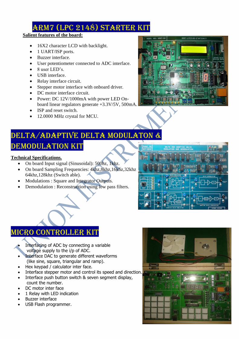
Delta/adaptive delta modulaton & Demodulation KIT Technical Specifications.
On board Input signal (Sinusoidal): 500hz, 1khz.
On board Sampling Frequencies: 4khz,8khz,16khz,32khz
64khz,128khz (Switch able).
Modulations : Square and Integrator Outputs.
Demodulation : Reconstruction using low pass filters.
Micro controller kIT
Interfacing of ADC by connecting a variable voltage supply to the i/p of ADC.
Interface DAC to generate different waveforms (like sine, square, triangular and ramp).
Hex keypad / calculator inter face. Interface stepper motor and control its speed and direction. Interface push button switch & seven segment display,
count the number.
DC motor inter face 1 Relay with LED indication Buzzer interface USB Flash programmer.
ARM7 (LPC 2148) STARTER KIT Salient features of the board:
16X2 character LCD with backlight.
1 UART/ISP ports.
Buzzer interface.
User potentiometer connected to ADC interface.
8 user LED’s.
USB interface.
Relay interface circuit.
Stepper motor interface with onboard driver.
DC motor interface circuit.
Power: DC 12V/1000mA with power LED On-
board linear regulators generate +3.3V/5V, 500mA.
ISP and reset switch.
12.0000 MHz crystal for MCU.

Advandced fpga kIT
Spartan 6 Advanced Board Model No VFGA-F-2.0
USB Downloading and Built in following Interface modules
16X2 LCD Display
DC Motor Interface
Stepper Motor Interface
Relay Interface
ADC Interface DAC Interface
Buzzer Interface
Mobile communication trainer kIT
Hardware Specifications
Dual band 900 / 1800 MHz GSM / GPRS Modem.
Data, SMS, Voice.
Remote control by AT commands (according to GSM
07.07 and GSM 07.05).
Maximum output power 2W for GSM 900: 1W for GSM
1800.
Input voltage 5.5V to 12V DC.
Current 1.8A peak at 5.5V, 330mA average at 5.5V
Onboard Details:
Antenna connection port
Test point for Antenna Signal GMSK_Mode
Test point for Battery Voltage (Output Charging Voltage)
Test point for Vibrator PWM signal
Test point for Buzzer PWM signal
RS- 232 Port using PC and GSM Module connection
RS- 232 Port using CPU and GSM Module connection
(Mobile trainer works like Standalone)
Vibrator ON/OFF Switch
CPU Section
GSM Module (SIM900D)
Hand Free Unit (Include Mike and Speaker I/O Signals)
SIM Signals Section
Audio Output signal
Audio input signal
Power supply Different Voltages
LCD Power ON/OFF switch
4*4 matrix Keyboard Signals section
LCD Signals Section
LCD Display (LAMPEX_LG128642_Dispaly)
20. 4*4 Matrix Keyboard

UNION INTRUMENTS #17 & 18, 4th floor, Hanumathra Arcade
60 feet road, Pattegarapalya, Bangalore-560072
KARNATAKA-INDIA
+91-953877189, 8951256363, 9066195428
ABOUT US
Dear Customers,
We take immense pleasure to introduce ourselves as one of
the leading manufacturers and distributors of Education lab
equipments in India.
Having industry experience of more than 05 years and
being associated with some of the best companies in the field,
we offer wide range of quality products in test & Measurements,
Digital &Analog Communication, Fiber optic Communication,
Microwave Communication, Embedded Systems, Network
Security Systems, Transmission line, Antenna & RF
Communication etc., Our products are designed to suit
Educational needs.