Embed Size (px)
DESCRIPTION
CAT - 2013 - Industrial Controls Short Form
Citation preview

SIRIUS
Industrial Controls
Answers for industry.
CatalogueSFC
Edition2013
sfc_umschlag_2013_en.indd 3sfc_umschlag_2013_en.indd 3 11.12.2012 08:32:3811.12.2012 08:32:38
© Siemens AG 2012

All product designations may be registered trademarks or product names of Siemens AG or other supplying companies. Third parties using these trademarks or product names for their own purposes may infringe upon the rights of the trademark owners.
Further information about industrial controls:www.siemens.com/sirius
Related catalogues Other information
Registered trademarks Technical Assistance
Industrial Controls IC 10SIRIUS
E86060-K1010-A101-A2-7600
Industrial Controls IC 10 NSIRIUS News
E86060-K1010-A221-A1-7600
Low-Voltage Power Distribution and LV 10.1Electrical Installation Technology SENTRON Protection, Switching, Measuring and Monitoring Devices
E86060-K8250-A101-A2-7600
Safety Integrated SI 10Safety Technology forFactory Automation
E86060-K7010-A101-A2-7600
Industrial Communication IK PISIMATIC NET
E86060-K6710-A101-B7-7600
SIMATIC ST 70Products forTotally Integrated Automation and Micro Automation
E86060-K4670-A101-B3-7600
SIMOTICS Low-Voltage Motors D 81.1Frame sizes 63 to 450Power 0.09 to 1250 kW
E86060-K5581-A111-A4-7600
SITRAIN ITCTraining for Automation and Industrial Solutions
Only available in GermanE86060-K6850-A101-C3
Products for Automation CA 01and DrivesInteractive Catalogue
DVD: E86060-D4001-A510-D2-7600
Industry MallInformation and Ordering Platformin the Internet:
www.siemens.com/industrymall
Information and Download CenterDigital versions of the catalogues are available in the Internet
www.siemens.com/sirius/catalogs
Response E-mailPlease send your comments and suggestions for improvement [email protected] (include the catalogue name in the subject field)
Technical AssistanceExpert technical assistance for Industrial controls:Tel.: +49 (911) 895-5900Fax: +49 (911) 895-5907
E-Mail: [email protected]
U2_SFC_2013_en.fm Seite 1 Montag, 10. Dezember 2012 10:09 10
© Siemens AG 2012

SIRIUSIndustrial Controls
Short Form Catalogue · 2013
Supersedes: Short Form Catalogue · 2012
Prices are:1. effective from 1st October 2012.2. quoted in Pounds Sterling.3. exclusive of Value Added Tax which will be added to the contract price at the rate applicable at the time of invoicing.4. subject to variation at any time.
For the latest updates of this catalogue, please visit our Industry Mall:www.siemens.com/industrymall
The products contained in this catalogue can also be found in the interactive catalogue CA 01.Order No.: E86060-D4001-A510-D2-7600 (DVD)
Contact your local Siemens branch for further information
© Siemens AG 2012
The products and sys-tems described in this catalogue are manufac-tured/distributed under application of a certified quality management system in accordance with DIN EN ISO 9001 (Certified Registration No. see Appendix to IC 10 • 2012). The certif-icate is recognized by all IQNet countries.
2 Answers for Industry
413
Motor Starter Protectors/Circuit Breakers 3RV2 up to 40 A3RV1 up to 100 A
714
Power Contactors for Switching Motors3RT2, 3 ... 18,5 kW3RT1, 15 ... 250 kW
12 3RA2 Contactor Assemblies
17 3RH2 Contactor Relays
18 3RV29 Infeed System
22 3RA6 Fuseless Compact Starters
26 3RW Soft Starters
2930
Overload Relays:3RU2 Thermal Overload Relays3RB2, 3RB3 Solid-State Overload Relays
32 3RR2 Monitoring Relays
34 3SB3 Pushbuttons and Indicator Lights, 22 mm
41 6EP1 Regulated Power Supplies
42 3LD Main Control and EMERGENCY-STOP Switches up to 125 A
43 5SY Miniature Circuit Breakers
45 Motor Power,Motor Nominal Current
46 Conditions of Sale and Delivery,Export regulations
Printed on paper from sustainably managed forests and controlled sources.
www.pefc.org
SFC_01.fm Seite 1 Donnerstag, 13. Dezember 2012 7:41 07
© Siemens AG 2012

2 Siemens Short Form Catalogue · 2013
SFC_2012.book Seite 2 Montag, 10. Dezember 2012 8:19 08
© Siemens AG 2012
3Siemens Short Form Catalogue · 2013
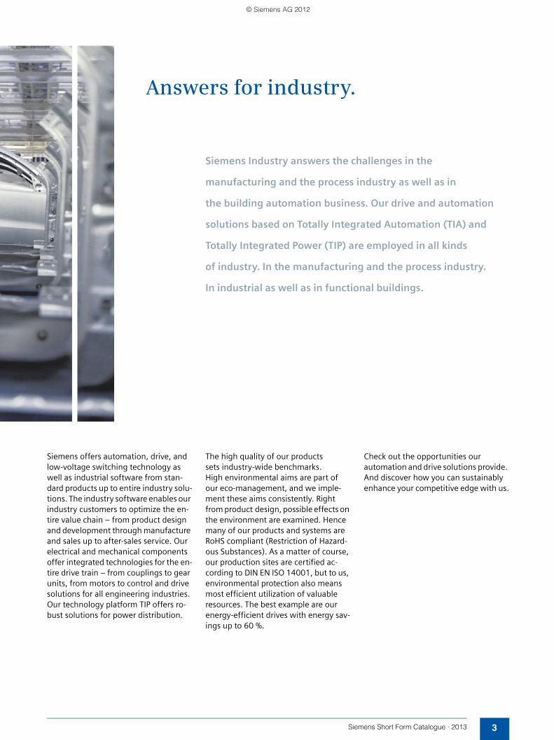
Answers for industry.
Siemens Industry answers the challenges in the
manufacturing and the process industry as well as in
the building automation business. Our drive and automation
solutions based on Totally Integrated Automation (TIA) and
Totally Integrated Power (TIP) are employed in all kinds
of industry. In the manufacturing and the process industry.
In industrial as well as in functional buildings.
Siemens offers automation, drive, and low-voltage switching technology as well as industrial software from stan-dard products up to entire industry solu-tions. The industry software enables our industry customers to optimize the en-tire value chain – from product design and development through manufacture and sales up to after-sales service. Our electrical and mechanical components offer integrated technologies for the en-tire drive train – from couplings to gear units, from motors to control and drive solutions for all engineering industries. Our technology platform TIP offers ro-bust solutions for power distribution.
The high quality of our products sets industry-wide benchmarks. High environmental aims are part of our eco-management, and we imple-ment these aims consistently. Right from product design, possible effects on the environment are examined. Hence many of our products and systems are RoHS compliant (Restriction of Hazard-ous Substances). As a matter of course, our production sites are certified ac-cording to DIN EN ISO 14001, but to us, environmental protection also means most efficient utilization of valuable resources. The best example are our energy-efficient drives with energy sav-ings up to 60 %.
Check out the opportunities our automation and drive solutions provide. And discover how you can sustainably enhance your competitive edge with us.
SFC_2012.book Seite 3 Montag, 10. Dezember 2012 8:19 08
© Siemens AG 2012
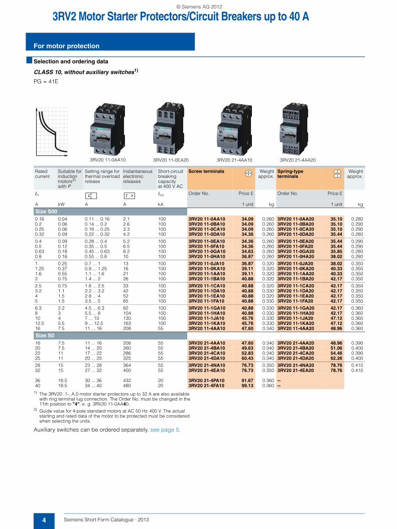
3RV2 Motor Starter Protectors/Circuit Breakers up to 40 A
For motor protection
4 Siemens Short Form Catalogue · 2013
■ Selection and ordering data
CLASS 10, without auxiliary switches1)
PG = 41E
1) The 3RV20 .1-..A.0 motor starter protectors up to 32 A are also available with ring terminal lug connection. The Order No. must be changed in the 11th position to "4": e. g. 3RV20 11-0AA40.
2) Guide value for 4-pole standard motors at AC 50 Hz 400 V. The actual starting and rated data of the motor to be protected must be considered when selecting the units.
Auxiliary switches can be ordered separately, see page 5.
Rated current
Suitable for induction motors2) with P
Setting range for thermal overload release
Instantaneous electronic releases
Short-circuit breaking capacity at 400 V AC
Screw terminals Weightapprox.
Spring-typeterminals
Weightapprox.
In Icu Order No. Price £ Order No. Price £
A kW A A kA 1 unit kg 1 unit kg
Size S000.16 0.04 0.11 ... 0.16 2.1 100 3RV20 11-0AA10 34.09 0.260 3RV20 11-0AA20 35.10 0.2800.2 0.06 0.14 ... 0.2 2.6 100 3RV20 11-0BA10 34.09 0.260 3RV20 11-0BA20 35.10 0.2900.25 0.06 0.18 ... 0.25 3.3 100 3RV20 11-0CA10 34.09 0.260 3RV20 11-0CA20 35.10 0.2900.32 0.09 0.22 ... 0.32 4.2 100 3RV20 11-0DA10 34.36 0.260 3RV20 11-0DA20 35.44 0.280
0.4 0.09 0.28 ... 0.4 5.2 100 3RV20 11-0EA10 34.36 0.260 3RV20 11-0EA20 35.44 0.2900.5 0.12 0.35 ... 0.5 6.5 100 3RV20 11-0FA10 34.36 0.260 3RV20 11-0FA20 35.44 0.2900.63 0.18 0.45 ... 0.63 8.2 100 3RV20 11-0GA10 34.63 0.260 3RV20 11-0GA20 35.85 0.2800.8 0.18 0.55 ... 0.8 10 100 3RV20 11-0HA10 36.87 0.260 3RV20 11-0HA20 38.02 0.280
1 0.25 0.7 ... 1 13 100 3RV20 11-0JA10 36.87 0.320 3RV20 11-0JA20 38.02 0.3501.25 0.37 0.9 ... 1.25 16 100 3RV20 11-0KA10 39.11 0.320 3RV20 11-0KA20 40.33 0.3501.6 0.55 1.1 ... 1.6 21 100 3RV20 11-1AA10 39.11 0.320 3RV20 11-1AA20 40.33 0.3502 0.75 1.4 ... 2 26 100 3RV20 11-1BA10 40.88 0.320 3RV20 11-1BA20 42.17 0.350
2.5 0.75 1.8 ... 2.5 33 100 3RV20 11-1CA10 40.88 0.320 3RV20 11-1CA20 42.17 0.3503.2 1.1 2.2 ... 3.2 42 100 3RV20 11-1DA10 40.88 0.330 3RV20 11-1DA20 42.17 0.3504 1.5 2.8 ... 4 52 100 3RV20 11-1EA10 40.88 0.320 3RV20 11-1EA20 42.17 0.3505 1.5 3.5 ... 5 65 100 3RV20 11-1FA10 40.88 0.330 3RV20 11-1FA20 42.17 0.350
6.3 2.2 4.5 ... 6.3 82 100 3RV20 11-1GA10 40.88 0.330 3RV20 11-1GA20 42.17 0.3608 3 5.5 ... 8 104 100 3RV20 11-1HA10 40.88 0.330 3RV20 11-1HA20 42.17 0.36010 4 7 ... 10 130 100 3RV20 11-1JA10 45.76 0.330 3RV20 11-1JA20 47.12 0.36012.5 5.5 9 ... 12.5 163 100 3RV20 11-1KA10 45.76 0.330 3RV20 11-1KA20 47.12 0.36016 7.5 11 ... 16 208 55 3RV20 11-4AA10 47.60 0.340 3RV20 11-4AA20 48.96 0.360
Size S016 7.5 11 ... 16 208 55 3RV20 21-4AA10 47.60 0.340 3RV20 21-4AA20 48.96 0.39020 7.5 14 ... 20 260 55 3RV20 21-4BA10 49.63 0.340 3RV20 21-4BA20 51.06 0.40022 11 17 ... 22 286 55 3RV20 21-4CA10 52.83 0.340 3RV20 21-4CA20 54.46 0.39025 11 20 ... 25 325 55 3RV20 21-4DA10 60.43 0.340 3RV20 21-4DA20 62.26 0.400
28 15 23 ... 28 364 55 3RV20 21-4NA10 76.73 0.350 3RV20 21-4NA20 78.76 0.41032 15 27 ... 32 400 55 3RV20 21-4EA10 76.73 0.350 3RV20 21-4EA20 78.76 0.410
36 18.5 30 ... 36 432 20 3RV20 21-4PA10 91.67 0.360 --40 18.5 34 ... 40 480 20 3RV20 21-4FA10 99.13 0.360 --
3RV20 11-0EA20 3RV20 21-4AA10 3RV20 21-4AA203RV20 11-0AA10
SFC_2012.book Seite 4 Montag, 10. Dezember 2012 8:19 08
© Siemens AG 2012

3RV2 Motor Starter Protectors/Circuit Breakers up to 40 A
5Siemens Short Form Catalogue · 2013
Mountable accessories
■ Selection and ordering data
PG = 41E
1) The link modules for motor starter protector to contactor cannot be used for the 3RV2. 21-4PA1. and 3RV2. 21-4FA1. motor starter protectors.
2) A spacer for height compensation on AC contactors size S0 is optionally available.
Note:
Link modules can be used up to max. 32 A.
Version For motor starter protectors
Screw terminals Weightapprox.
Spring-type terminals
Weightapprox.
Size
Order No. Price £ Order No. Price £
1 unit kg 1 unit kg
Auxiliary switches
3RV29 01-1E
3RV29 01-2E
3RV29 01-1G
Transverse auxiliary switchesfor front mounting
1 CO S00, S0 3RV29 01-1D 5.17 0.014 --1 NO + 1 NC 3RV29 01-1E 6.25 0.016 3RV29 01-2E 6.31 0.0162 NO 3RV29 01-1F 6.25 0.017 3RV29 01-2F 6.31 0.017
Solid-state compatible transverse auxiliary switches for mounting on the front, for operation in dusty atmosphere and in solid-state circuits with low operating currents
1 CO S00, S0 3RV29 01-1G 19.42 0.015 --
3RV29 01-0H
Covers for transverse auxiliary switch
S00, S0 3RV29 01-0H 2.87 0.001 --
3RV29 01-1A
3RV29 01-2A
Lateral auxiliary switchesmountable on the left
1 NO + 1 NC S00, S0 3RV29 01-1A 6.22 0.036 3RV29 01-2A 6.31 0.0352 NO 3RV29 01-1B 6.22 0.037 3RV29 01-2B 6.31 0.0352 NC 3RV29 01-1C 6.22 0.037 3RV29 01-2C 6.31 0.0352 NO + 2 NC 3RV29 01-1J 14.19 0.066 --
Actuating voltage of contactor Size Order No. Price £ PG Weightapprox.3RT2 contactors 3RV2 motor starter
protectors
1 unit kg
Link modules for motor starter protector to contactor1)
3RA29 21-1AA00
For mechanical and electrical connection between motor starter protector and contactor with screw terminals
Screw terminals
Single-unit packaging
AC/DC S00 S00/S0 3RA19 21-1DA00 3.34 41B 0.028AC S0 S00/S0 3RA29 21-1AA00 4.21 41B 0.001DC S0 S00/S0 3RA29 21-1BA00 4.21 41B 0.001
Multi-unit packaging (10 units)
AC/DC S00 S00/S0 3RA19 21-1D 2.76 41B 0.021AC S0 S00/S0 3RA29 21-1A 3.60 41B 0.001DC S0 S00/S0 3RA29 21-1B 3.60 41B 0.001
3RA29 11-2AA00
For mechanical and electrical connection between motor starter protector and contactor with spring-type terminals
Spring-type terminals
Single-unit packaging
AC/DC S00 S00 3RA29 11-2AA00 4.07 41B 0.040AC2) S0 S0 3RA29 21-2AA00 4.28 41B 0.077DC S0 S0 3RA29 21-2AA00 4.28 41B 0.077
Multi-unit packaging (10 units)
AC/DC S00 S00 3RA29 11-2A 3.40 41B 0.400AC2) S0 S0 3RA29 21-2A 3.67 41B 0.770DC S0 S0 3RA29 21-2A 3.67 41B 0.770
Spacers2)
for compensating the height on AC contactors
Single-unit packaging S0 S0 3RA29 11-1CA00 1.29 41B 0.001Multi-unit packaging (5 units) S0 S0 3RA29 11-1C 1.02 41B 0.001
SFC_2012.book Seite 5 Montag, 10. Dezember 2012 8:19 08
© Siemens AG 2012

3RV2 Motor Starter Protectors/Circuit Breakers up to 40 A
Mountable accessories
6 Siemens Short Form Catalogue · 2013
1) Clamping together S00 and S0 circuit-breakers is not possible due to the different modular spacings and the different heights of the terminals. A connector is available for connecting busbars from size S00 to size S0. See Order No.: 3RV19 15-5DB or see 3RV19 Infeed System in Catalogue IC 10.
Modular spacing
Number of circuit breakers that can be connected
Rated current In at 690 V
For circuit-breakers Order No. Price £ PriceGroup
Weightapprox.
Without lateral accesso-ries
Incl.lateral auxiliary switch
With auxiliary trip unit
mm A Size 1 unit kg
Three-phase busbar systems
3RV19 15-1AB
3RV19 15-1BB
3RV19 15-1CB
3RV19 15-1DB
For feeding several circuit breakers with screw terminals, mounted side by side on standard mounting rails, insulated, with touch protection
45 2 -- -- 63 S00, S01) 3RV19 15-1AB 6.25 41E 0.0443 S00, S01) 3RV19 15-1BB 7.67 41E 0.0714 S00, S01) 3RV19 15-1CB 8.42 41E 0.0995 S00, S01) 3RV19 15-1DB 9.51 41E 0.124
55 2 -- -- 108 S2 3RV19 35-1A 11.20 41E 0.1403 S2 3RV19 35-1B 13.78 41E 0.2144 S2 3RV19 35-1C 16.23 41E 0.295
Connecting piece for three-phase busbars
3RV19 15-5DB
For connecting 3-phase busbars for circuit-breakers of size S0 (left) to size S00 (right)45 -- -- -- -- S00, S0 3RV19 15-5DB 6.52 41E 0.042
Three-phase feeder terminals
3RV29 25-5AB
Connection from topsolid or stranded or finely stranded with end sleeve,Conductor cross-section 2.5 ... 16 mm²
S00, S0 3RV29 25-5AB 6.45 41E 0.045
3RV29 15-5B
Connection from belowThis terminal is connected in place of a switch, please take the space requirement into accountsolid or stranded or finely stranded with end sleeve,Conductor cross section 2.5 ... 16 mm²
S00, S0 3RV29 15-5B 8.96 41E 0.109
SFC_2012.book Seite 6 Montag, 10. Dezember 2012 8:19 08
© Siemens AG 2012
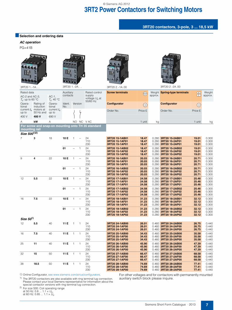
3RT2 Power Contactors for Switching Motors
7Siemens Short Form Catalogue · 2013
3RT20 contactors, 3-pole, 3 ... 18,5 kW
■ Selection and ordering data
AC operation
PG=41B
Online-Configurator, see www.siemens.com/sirius/configurators.1) The 3RT20 contactors are also available with ring terminal lug connection.
Please contact your local Siemens representative for information about the special contactor versions with ring terminal lug connection.
2) For size S00: Coil operating range at 50 Hz: 0.8 ... 1.1 × Us, at 60 Hz: 0.85 ... 1.1 × Us.
For other voltages and for contactors with permanently mounted auxiliary switch block please inquire.
3RT20 1.-1A. . . 3RT20 1.-2A. . . 3RT20 2.-1A.00 3RT20 2.-2A.00
Rated data Auxiliary contacts
Rated control supply voltage Us at 50/60 Hz
Screw terminals Weightapprox.
Spring-type terminals Weightapprox.AC-2 and AC-3,
Tu: up to 60 °CAC-1, Tu: 40 °C
Opera-tional current Ie up to
Rating of induction motors at 50 Hz and
Opera-tional current Ie up to
Ident. No.
Version Configurator Configurator
Order No. Price £ Order No. Price £
400 V 400 V 690 V
A kW A NO NC V AC 1 unit kg 1 unit kg
For screw and snap-on mounting onto TH 35 standard mounting rail Size S001)2) 7 3 18 10 E 1 -- 24 3RT20 15-1AB01 18.47 0.280 3RT20 15-2AB01 19.01 0.300
110 3RT20 15-1AF01 18.47 0.280 3RT20 15-2AF01 19.01 0.300230 3RT20 15-1AP01 18.47 0.280 3RT20 15-2AP01 19.01 0.300
01 -- 1 24 3RT20 15-1AB02 18.47 0.280 3RT20 15-2AB02 19.01 0.300110 3RT20 15-1AF02 18.47 0.280 3RT20 15-2AF02 19.01 0.300230 3RT20 15-1AP02 18.47 0.280 3RT20 15-2AP02 19.01 0.300
9 4 22 10 E 1 -- 24 3RT20 16-1AB01 20.03 0.280 3RT20 16-2AB01 20.71 0.300110 3RT20 16-1AF01 20.03 0.280 3RT20 16-2AF01 20.71 0.300230 3RT20 16-1AP01 20.03 0.280 3RT20 16-2AP01 20.71 0.300
01 -- 1 24 3RT20 16-1AB02 20.03 0.280 3RT20 16-2AB02 20.71 0.300110 3RT20 16-1AF02 20.03 0.280 3RT20 16-2AF02 20.71 0.300230 3RT20 16-1AP02 20.03 0.280 3RT20 16-2AP02 20.71 0.300
12 5.5 22 10 E 1 -- 24 3RT20 17-1AB01 24.58 0.280 3RT20 17-2AB01 25.46 0.300110 3RT20 17-1AF01 24.58 0.280 3RT20 17-2AF01 25.46 0.300230 3RT20 17-1AP01 24.58 0.280 3RT20 17-2AP01 25.46 0.300
01 -- 1 24 3RT20 17-1AB02 24.58 0.280 3RT20 17-2AB02 25.46 0.300110 3RT20 17-1AF02 24.58 0.280 3RT20 17-2AF02 25.46 0.300230 3RT20 17-1AP02 24.58 0.280 3RT20 17-2AP02 25.46 0.300
16 7.5 22 10 E 1 -- 24 3RT20 18-1AB01 31.23 0.280 3RT20 18-2AB01 32.12 0.300110 3RT20 18-1AF01 31.23 0.280 3RT20 18-2AF01 32.12 0.300230 3RT20 18-1AP01 31.23 0.280 3RT20 18-2AP01 32.12 0.300
01 -- 1 24 3RT20 18-1AB02 31.23 0.280 3RT20 18-2AB02 32.12 0.300110 3RT20 18-1AF02 31.23 0.280 3RT20 18-2AF02 32.12 0.300230 3RT20 18-1AP02 31.23 0.280 3RT20 18-2AP02 32.12 0.300
Size S01)
12 5.5 40 11 E 1 1 24 3RT20 24-1AB00 26.01 0.460 3RT20 24-2AB00 26.75 0.440110 3RT20 24-1AF00 26.01 0.460 3RT20 24-2AF00 26.75 0.440230 3RT20 24-1AP00 26.01 0.460 3RT20 24-2AP00 26.75 0.440
16 7.5 40 11 E 1 1 24 3RT20 25-1AB00 34.43 0.460 3RT20 25-2AB00 35.58 0.440110 3RT20 25-1AF00 34.43 0.460 3RT20 25-2AF00 35.58 0.440230 3RT20 25-1AP00 34.43 0.460 3RT20 25-2AP00 35.58 0.440
25 11 40 11 E 1 1 24 3RT20 26-1AB00 45.90 0.460 3RT20 26-2AB00 47.39 0.440110 3RT20 26-1AF00 45.90 0.460 3RT20 26-2AF00 47.39 0.440230 3RT20 26-1AP00 45.90 0.460 3RT20 26-2AP00 47.39 0.440
32 15 50 11 E 1 1 24 3RT20 27-1AB00 66.47 0.460 3RT20 27-2AB00 68.58 0.440110 3RT20 27-1AF00 66.47 0.460 3RT20 27-2AF00 68.58 0.440230 3RT20 27-1AP00 66.47 0.460 3RT20 27-2AP00 68.58 0.440
38 18.5 50 11 E 1 1 24 3RT20 28-1AB00 74.69 0.460 3RT20 28-2AB00 77.41 0.440110 3RT20 28-1AF00 74.69 0.460 3RT20 28-2AF00 77.41 0.440230 3RT20 28-1AP00 74.69 0.460 3RT20 28-2AP00 77.41 0.440
SFC_2012.book Seite 7 Montag, 10. Dezember 2012 8:19 08
© Siemens AG 2012

3RT2 Power Contactors for Switching Motors
3RT20 contactors, 3-pole, 3 ... 18,5 kW
8 Siemens Short Form Catalogue · 2013
DC operation · DC solenoid system
PG = 41B
Online-Configurator, see www.siemens.com/sirius/configurators.1) The 3RT20 contactors are also available with ring terminal lug connection.
Please contact your local Siemens representative for information about the special contactor versions with ring terminal lug connection.
For other voltages and for contactors with permanently mounted auxiliary switch block please inquire.
3RT20 1.-1B. . . 3RT20 1.-2B. . . 3RT20 2.-1B.40 3RT20 2.-2B.40
Rated data Auxiliary contacts
Rated control supply voltage Us
Screw terminals Weightapprox.
Spring-type terminals Weightapprox.AC-2 and AC-3,
Tu: up to 60 °CAC-1, Tu: 40 °C
Opera-tional current Ie up to
Rating of induction motors at 50 Hz and
Opera-tional current Ie up to
Ident. No.
Version Configurator Configurator
Order No. Price £ Order No. Price £
400 V 400 V 690 V
A kW A NO NC V DC 1 unit kg 1 unit kg
For screw and snap-on mounting onto TH 35 standard mounting rail Size S001)
7 3 18 10 E 1 -- 24 3RT20 15-1BB41 21.80 0.280 3RT20 15-2BB41 22.47 0.300220 3RT20 15-1BM41 21.80 0.280 3RT20 15-2BM41 22.47 0.300
01 -- 1 24 3RT20 15-1BB42 21.80 0.280 3RT20 15-2BB42 22.47 0.300220 3RT20 15-1BM42 21.80 0.280 3RT20 15-2BM42 22.47 0.300
9 4 22 10 E 1 -- 24 3RT20 16-1BB41 23.36 0.280 3RT20 16-2BB41 24.04 0.300220 3RT20 16-1BM41 23.36 0.280 3RT20 16-2BM41 24.04 0.300
01 -- 1 24 3RT20 16-1BB42 23.36 0.280 3RT20 16-2BB42 24.04 0.300220 3RT20 16-1BM42 23.36 0.280 3RT20 16-2BM42 24.04 0.300
12 5.5 22 10 E 1 -- 24 3RT20 17-1BB41 28.38 0.280 3RT20 17-2BB41 29.26 0.300220 3RT20 17-1BM41 28.38 0.280 3RT20 17-2BM41 29.26 0.300
01 -- 1 24 3RT20 17-1BB42 28.38 0.280 3RT20 17-2BB42 29.26 0.300220 3RT20 17-1BM42 28.38 0.280 3RT20 17-2BM42 29.26 0.300
16 7.5 22 10 E 1 -- 24 3RT20 18-1BB41 50.25 0.280 3RT20 18-2BB41 51.81 0.300220 3RT20 18-1BM41 50.25 0.280 3RT20 18-2BM41 51.81 0.300
01 -- 1 24 3RT20 18-1BB42 50.25 0.280 3RT20 18-2BB42 51.81 0.300220 3RT20 18-1BM42 50.25 0.280 3RT20 18-2BM42 51.81 0.300
Size S01)
12 5.5 40 11 E 1 1 24 3RT20 24-1BB40 51.13 0.580 3RT20 24-2BB40 52.76 0.620220 3RT20 24-1BM40 51.13 0.580 3RT20 24-2BM40 52.76 0.620
16 7.5 40 11 E 1 1 24 3RT20 25-1BB40 61.52 0.580 3RT20 25-2BB40 63.35 0.620220 3RT20 25-1BM40 61.52 0.580 3RT20 25-2BM40 63.35 0.620
25 11 40 11 E 1 1 24 3RT20 26-1BB40 73.33 0.580 3RT20 26-2BB40 76.05 0.620220 3RT20 26-1BM40 73.33 0.580 3RT20 26-2BM40 76.05 0.620
32 15 50 11 E 1 1 24 3RT20 27-1BB40 99.81 0.580 3RT20 27-2BB40 103.21 0.620220 3RT20 27-1BM40 99.81 0.580 3RT20 27-2BM40 103.21 0.620
38 18.5 50 11 E 1 1 24 3RT20 28-1BB40 109.32 0.580 3RT20 28-2BB40 113.39 0.620220 3RT20 28-1BM40 109.32 0.580 3RT20 28-2BM40 113.39 0.620
SFC_2012.book Seite 8 Montag, 10. Dezember 2012 8:19 08
© Siemens AG 2012

3RT2 Power Contactors for Switching Motors
9Siemens Short Form Catalogue · 2013
Auxiliary switch blocks
■ Selection and ordering data
PG = 41B
1) With size S00, mounting according to EN 50012 is permitted only on basic units which have no NC contact integrated.
2) Ident. No. 41, 32 and 23 according to EN 50012 is also possible. Please note the corresponding circuit diagrams for mounting 3RH29 11-1DA.. on the left.
3RH29 11-1DA02 3RH29 11-2DA02
For contac-tors/ contac-tor relays
Contactor with AS block
Auxiliary contacts Screw terminals Weightapprox.
Spring-typeterminals
Weightapprox.
Ident. No. Version
Order No. Price £ Order No. Price £
Type NO NC 1 unit kg 1 unit kg
Laterally mountable auxiliary switch blocks acc. to EN 50012 Mounting on the right Size S001)2) Left Right
3RT20 1. Ident. No. 10
12 -- 2 -- 3RH29 11-1DA02 7.94 0.020 3RH29 11-2DA02 8.22 0.050
21 1 1 -- 3RH29 11-1DA11 7.94 0.040 3RH29 11-2DA11 8.22 0.050
Size S0 Left Right
3RT20 2. Ident. No. 11
13 -- 2 -- 3RH29 21-1DA02 7.94 0.050 3RH29 21-2DA02 8.22 0.050
22 1 1 -- 3RH29 21-1DA11 7.94 0.050 3RH29 21-2DA11 8.22 0.050
31 2 -- -- 3RH29 21-1DA20 7.94 0.050 3RH29 21-2DA20 8.22 0.050
Laterally mountable auxiliary switch blocks acc. to EN 50005 Mounting on the right and/or on the leftSize S001)2) Left Right
3RT20 1., Ident. No. 10
02 -- 2 3RH29 11-1DA02 7.94 0.040 3RH29 11-2DA02 8.22 0.050
11 1 1 3RH29 11-1DA11 7.94 0.040 3RH29 11-2DA11 8.22 0.050
20 2 -- 3RH29 11-1DA20 7.94 0.040 3RH29 11-2DA20 8.22 0.050
Size S0 Left Right
3RT20 2. 02 -- 2 3RH29 21-1DA02 7.94 0.050 3RH29 21-2DA02 8.22 0.050
11 1 1 3RH29 21-1DA11 7.94 0.050 3RH29 21-2DA11 8.22 0.050
20 2 -- 3RH29 21-1DA20 7.94 0.050 3RH29 21-2DA20 8.22 0.050
22
21
32
31
22
21
34
33
32
31
42
41
32
31
44
43
54
53
64
63
42
41
52
51
22
21
32
31
42
41
22
21
34
33
54
53
44
43
24
23
34
33
54
53
52
51
62
61
32
31
42
41
52
51
64
63
32
31
44
43
54
53
64
63
34
33
44
43
SFC_2012.book Seite 9 Montag, 10. Dezember 2012 8:19 08
© Siemens AG 2012
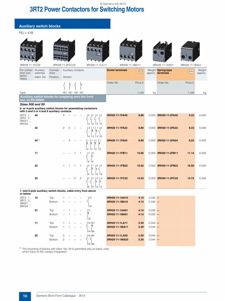
3RT2 Power Contactors for Switching Motors
Auxiliary switch blocks
10 Siemens Short Form Catalogue · 2013
PG = 41B
1) The mounting of blocks with Ident. No. 04 is permitted only on basic units which have no NC contact integrated.
3RH29 11-1FC22 3RH29 11-2FAC22 3RH29 11-1LA11 3RH29 11-1MA11 3RH29 11-1AA01 3RH29 11-1BA01
For contac-tors/ con-tactor relays
Auxiliary switches
Connec-tions
Auxiliary contacts Screw terminals Weightapprox.
Spring-type terminals
Weightapprox.
Ident. No. Position Version
Order No. Price £ Order No. Price £
Type NO NC NO NC 1 unit kg 1 unit kg
Auxiliary switch blocks for snapping onto the front acc. to EN 50005Sizes S00 and S02- or 4-pole auxiliary switch blocks for assembling contactors with 3 and 5 or 4 and 6 auxiliary contacts
3RT2. 1., 3RT2. 2., 3RH21 .., 3RH24 ..
40 4 -- -- -- 3RH29 11-1FA40 8.89 0.050 3RH29 11-2FA40 9.23 0.049
22 2 2 -- -- 3RH29 11-1FA22 8.89 0.050 3RH29 11-2FA22 9.23 0.049
041) -- 4 -- -- 3RH29 11-1FA04 8.89 0.050 3RH29 11-2FA04 9.23 0.049
11 -- -- 1 1 3RH29 11-1FB11 10.66 0.050 3RH29 11-2FB11 11.14 0.049
22 1 1 1 1 3RH29 11-1FB22 16.02 0.050 3RH29 11-2FB22 16.50 0.049
22 -- -- 2 2 3RH29 11-1FC22 14.33 0.050 3RH29 11-2FC22 14.73 0.049
1- and 2-pole auxiliary switch blocks, cable entry from above or below
3RT2. 1., 3RT2. 2., 3RH21 .., 3RH24 ..
10 Top 1 -- -- -- 3RH29 11-1AA10 4.14 0.020 --
Bottom 1 -- -- -- 3RH29 11-1BA10 4.14 0.020 --
01 Top -- 1 -- -- 3RH29 11-1AA01 4.14 0.020 --
Bottom -- 1 -- -- 3RH29 11-1BA01 4.14 0.020 --
11 Top 1 1 -- -- 3RH29 11-1LA11 5.30 0.044 --
Bottom 1 1 -- -- 3RH29 11-1MA11 5.30 0.044 --
20 Top 2 -- -- -- 3RH29 11-1LA20 5.30 0.045 --
Bottom 2 -- -- -- 3RH29 11-1MA20 5.30 0.044 --
.4
.3
.4
.3
.4
.3
.4
.3
.2
.1
.2
.1
.4
.3
.4
.3
.2
.1
.2
.1
.2
.1
.2
.1
.6
.5
.8
.7
.8
.7
.6
.5
.2
.1
.4
.3
.6
.5
.6
.5
.8
.7
.8
.7
74
73
72
71
82
81
74
73
74
73
84
83
SFC_2012.book Seite 10 Montag, 10. Dezember 2012 8:19 08
© Siemens AG 2012
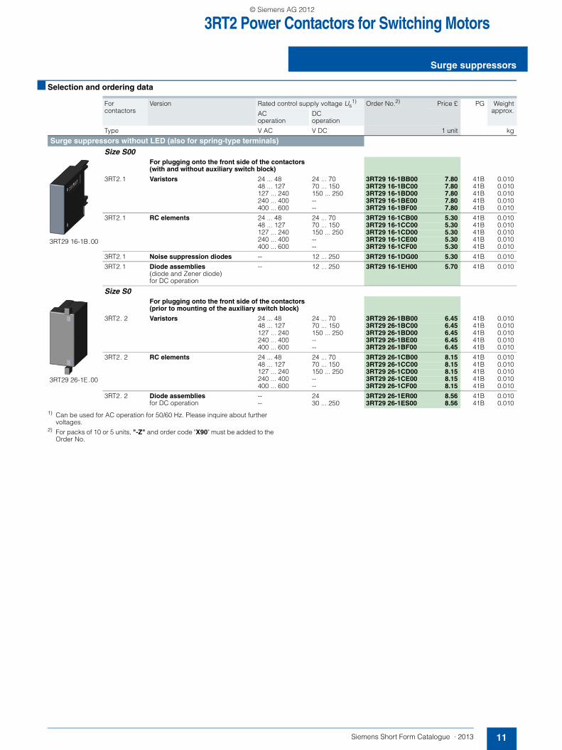
3RT2 Power Contactors for Switching Motors
11Siemens Short Form Catalogue · 2013
Surge suppressors
■ Selection and ordering data
1) Can be used for AC operation for 50/60 Hz. Please inquire about further voltages.
2) For packs of 10 or 5 units, "-Z" and order code "X90" must be added to the Order No.
For contactors
Version Rated control supply voltage Us1) Order No.2) Price £ PG Weight
approx.AC operation
DC operation
Type V AC V DC 1 unit kg
Surge suppressors without LED (also for spring-type terminals) Size S00
3RT29 16-1B.00
For plugging onto the front side of the contactors (with and without auxiliary switch block)
3RT2.1 Varistors 24 ... 48 24 ... 70 3RT29 16-1BB00 7.80 41B 0.01048 ... 127 70 ... 150 3RT29 16-1BC00 7.80 41B 0.010127 ... 240 150 ... 250 3RT29 16-1BD00 7.80 41B 0.010240 ... 400 -- 3RT29 16-1BE00 7.80 41B 0.010400 ... 600 -- 3RT29 16-1BF00 7.80 41B 0.010
3RT2.1 RC elements 24 ... 48 24 ... 70 3RT29 16-1CB00 5.30 41B 0.01048 ... 127 70 ... 150 3RT29 16-1CC00 5.30 41B 0.010127 ... 240 150 ... 250 3RT29 16-1CD00 5.30 41B 0.010240 ... 400 -- 3RT29 16-1CE00 5.30 41B 0.010400 ... 600 -- 3RT29 16-1CF00 5.30 41B 0.010
3RT2.1 Noise suppression diodes -- 12 ... 250 3RT29 16-1DG00 5.30 41B 0.010
3RT2.1 Diode assemblies (diode and Zener diode)for DC operation
-- 12 ... 250 3RT29 16-1EH00 5.70 41B 0.010
Size S0
3RT29 26-1E.00
For plugging onto the front side of the contactors (prior to mounting of the auxiliary switch block)
3RT2. 2 Varistors 24 ... 48 24 ... 70 3RT29 26-1BB00 6.45 41B 0.01048 ... 127 70 ... 150 3RT29 26-1BC00 6.45 41B 0.010127 ... 240 150 ... 250 3RT29 26-1BD00 6.45 41B 0.010240 ... 400 -- 3RT29 26-1BE00 6.45 41B 0.010400 ... 600 -- 3RT29 26-1BF00 6.45 41B 0.010
3RT2. 2 RC elements 24 ... 48 24 ... 70 3RT29 26-1CB00 8.15 41B 0.01048 ... 127 70 ... 150 3RT29 26-1CC00 8.15 41B 0.010127 ... 240 150 ... 250 3RT29 26-1CD00 8.15 41B 0.010240 ... 400 -- 3RT29 26-1CE00 8.15 41B 0.010400 ... 600 -- 3RT29 26-1CF00 8.15 41B 0.010
3RT2. 2 Diode assemblies for DC operation
-- 24 3RT29 26-1ER00 8.56 41B 0.010-- 30 ... 250 3RT29 26-1ES00 8.56 41B 0.010
SFC_2012.book Seite 11 Montag, 10. Dezember 2012 8:19 08
© Siemens AG 2012

3RA2 Contactor Assemblies
Components for customer assembly
12 Siemens Short Form Catalogue · 2013
■ Selection and ordering data
PG = 41B
1) When using the function modules for wye-delta starting, the wiring modules for the auxiliary current are not required.
2) Version in size S0 with spring-type terminals: Only the wiring modules for the main circuit are included. No connectors are included for the auxiliary and control circuit.
Note:
When the function modules for contactor assemblies for wye-delta starting are used, no other auxiliary switches are allowed to be mounted on the basic units.
3RA28 16-0EW20 3RA29 23-2AA1 3RA29 23-2AA2
For contactors
Size Version Screw terminals Weightapprox.
Spring-type terminals Weightapprox.
Type Order No. Price £1 unit kg
Order No. Price £1 unit kg
Function modules for wye-delta starting 3RT20 1, 3RT20 2
S00, S0 Comprising one basic module and two coupling modules.
Rated control supply voltage 24 ... 240 V AC/DC
Time setting range 0.5 ... 60 s (10, 30, 60 s selectable)
3RA28 16-0EW20 87.59 0.170 3RA28 16-0EW20 87.59 0.170
Accessories for 3RA28 function modules3RT20 1, 3RT20 2
S00, S0 Sealable covers 3RA29 10-0 2.99 0.002 3RA29 10-0 2.99 0.002
Assembly kits for making reversing contactor assemblies3RT20 1 S00-S00 The assembly kit contains:
mechanical interlock; 2 connecting clips for 2 contactors, wiring modules on the top and bottom
• For main, auxiliary and control circuits
3RA29 13-2AA1 8.35 0.001 3RA29 13-2AA2 8.69 0.001
3RT20 2 S0-S0 The assembly kit contains: mechanical interlock; 2 connecting clips for 2 contactors, wiring modules on the top and bottom
• For main, auxiliary and control circuits
3RA29 23-2AA1 12.56 0.001 --
• Only for main circuit2) -- 3RA29 23-2AA2 12.97 0.001
Assembly kits1) for making wye-delta contactor assemblies 3RT20 1 S00 The assembly kit contains:
mechanical interlock; 4 connecting clips, star jumper,wiring modules on the top and bottom
• For main, auxiliary and control circuits
3RA29 13-2BB1 6.52 0.001 3RA29 13-2BB2 6.72 0.001
3RT20 2 S0 The assembly kit contains: mechanical interlock; 4 connecting clips, star jumper,wiring modules on the top and bottom
• For main, auxiliary and control circuits
3RA29 23-2BB1 14.19 0.001 --
• Only for main circuit2) -- 3RA29 23-2BB2 14.60 0.001
SFC_2012.book Seite 12 Montag, 10. Dezember 2012 8:19 08
© Siemens AG 2012
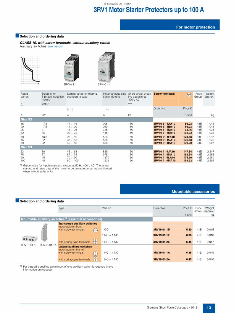
3RV1 Motor Starter Protectors up to 100 A
13Siemens Short Form Catalogue · 2013
For motor protection
■ Selection and ordering data
CLASS 10, with screw terminals, without auxiliary switchAuxiliary switches see below.
1) Guide value for 4-pole standard motors at 50 Hz 400 V AC. The actual starting and rated data of the motor to be protected must be considered when selecting the units.
■ Selection and ordering data
1) For tripped signalling a minimum of one auxiliary switch is required (more information on request).
Ratedcurrent
Suitable for 3-phase induction motors1)
Setting range for thermal overload release
Instantaneous elec-tronic trip unit
Short-circuit break-ing capacity at 400 V ACIcu
Screw terminals PriceGroup
Weightapprox.
In with P
Order No. Price £
A kW A A kA 1 unit kg
Size S216 7.5 11 ... 16 208 50 3RV10 31-4AA10 86.23 41E 1.04620 7.5 14 ... 20 260 50 3RV10 31-4BA10 86.23 41E 1.04325 11 18 ... 25 325 50 3RV10 31-4DA10 98.46 41E 1.03132 15 22 ... 32 416 50 3RV10 31-4EA10 105.92 41E 1.028
40 18.5 28 ... 40 520 50 3RV10 31-4FA10 123.58 41E 1.04745 22 36 ... 45 585 50 3RV10 31-4GA10 136.48 41E 1.03950 22 40 ... 50 650 50 3RV10 31-4HA10 139.20 41E 1.027
Size S363 30 45 ... 63 819 50 3RV10 41-4JA10 147.34 41E 2.24775 37 57 ... 75 975 50 3RV10 41-4KA10 163.64 41E 2.25390 45 70 ... 90 1170 50 3RV10 41-4LA10 174.50 41E 2.280100 45 80 ... 100 1235 50 3RV10 41-4MA10 193.52 41E 2.295
3RV10 31 3RV10 41
I >
Type Version Order No. Price £ PriceGroup
Weightapprox.
1 unit kg
Mountable auxiliary switches1) (essential accessories)Transverse auxiliary switchesmountable on frontwith screw terminals 1 CO 3RV19 01-1D 5.30 41E 0.015
1 NO + 1 NC 3RV19 01-1E 6.38 41E 0.018
with spring-type terminals 1 NO + 1 NC 3RV19 01-2E 6.45 41E 0.017
Lateral auxiliary switchesmountable on the leftwith screw terminals 1 NO + 1 NC 3RV19 01-1A 6.38 41E 0.045
with spring-type terminals 1 NO + 1 NC 3RV19 01-2A 6.45 41E 0.040
Mountable accessories
3RV19 01-1E 3RV19 01-1A
SFC_2012.book Seite 13 Montag, 10. Dezember 2012 8:19 08
© Siemens AG 2012

3RT1 Power Contactors for Switching Motors
3RT10 contactors, 3-pole, 15 ... 250 kW
14 Siemens Short Form Catalogue · 2013
■ Selection and ordering data
AC operation
AC/DC operation (40 Hz to 60 Hz, DC) ; Auxiliary and control conductors: screw terminals; withdrawable coils with integrated coil circuit (Varistor); Main conductors: busbar connections, for 3RT10 54 (55 kW) box terminals
Rated data Auxiliary contacts Rated control supply voltage Us
Screw terminals PriceGroup
Weightapprox.AC-2 and AC-3,
Tu: up to 60 °CAC-1, Tu: 40 °C
Operational current Ie up to
Ratings of induction motors at 50 Hz and
Operational current Ie up to
Ident. No.
Version Order No. Price £
500 V 400 V 690 V
A kW A NO NC AC 1 unit kg
For screw and snap-on mounting onto TH 35 and TH 75 standard mounting railSize S232 15 50 -- -- -- 24 V, 50 Hz 3RT10 34-1AB00 64.91 41B 0.850
110 V, 50 Hz 3RT10 34-1AF00 64.91 41B 0.850230 V, 50 Hz 3RT10 34-1AP00 64.91 41B 0.850
40 18.5 60 -- -- -- 24 V, 50 Hz 3RT10 35-1AB00 73.33 41B 0.850110 V, 50 Hz 3RT10 35-1AF00 73.33 41B 0.850230 V, 50 Hz 3RT10 35-1AP00 73.33 41B 0.850
50 22 60 -- -- -- 24 V, 50 Hz 3RT10 36-1AB00 97.10 41B 0.850110 V, 50 Hz 3RT10 36-1AF00 97.10 41B 0.850230 V, 50 hz 3RT10 36-1AP00 97.10 41B 0.850
Size S365 30 100 -- -- -- 110 V 3RT10 44-1AF00 137.84 41B 1.800
230 V 3RT10 44-1AP00 137.84 41B 1.800
80 37 120 -- -- -- 110 V 3RT10 45-1AF00 165.68 41B 1.800230 V 3RT10 45-1AP00 165.68 41B 1.800
95 45 120 -- -- -- 110 V 3RT10 46-1AF00 210.49 41B 1.800230 V 3RT10 46-1AP00 210.49 41B 1.800
3RT10 5 3RT10 6 3RT10 73RT10 4.-1A . 003RT10 3.-1A . 00
Rated data Auxiliary contacts, lateral
Rated control supply voltage Us
Screw terminals PriceGroup
Weightapprox.AC-2 and AC-3,
Tu: up to 60 °CAC-1, Tu: 40 °C
Operational current Ie up to
Ratings of induction motors at 50 Hz and
Operational current Ie up to
Order No. Price £
500 V 400 V 690 V
A kW A NO NC V AC/DC 1 unit kg
Conventional operating mechanismSize S6115 55 160 2 2 110 ... 127 3RT10 54-1AF36 285.86 41B 3.600
220 ... 240 3RT10 54-1AP36 285.86 41B 3.600
150 75 185 2 2 110 ... 127 3RT10 55-6AF36 349.69 41B 3.500220 ... 240 3RT10 55-6AP36 349.69 41B 3.500
185 90 215 2 2 110 ... 127 3RT10 56-6AF36 439.99 41B 3.500220 ... 240 3RT10 56-6AP36 439.99 41B 3.500
Size S10225 110 275 2 2 110 ... 127 3RT10 64-6AF36 497.03 41B 6.500
220 ... 240 3RT10 64-6AP36 497.03 41B 6.500
265 132 330 2 2 110 ... 127 3RT10 65-6AF36 699.37 41B 6.500220 ... 240 3RT10 65-6AP36 699.37 41B 6.500
300 160 330 2 2 110 ... 127 3RT10 66-6AF36 848.75 41B 6.500220 ... 240 3RT10 66-6AP36 848.75 41B 6.500
Size S12400 200 430 2 2 110 ... 127 3RT10 75-6AF36 1059.24 41B 10.500
220 ... 240 3RT10 75-6AP36 1059.24 41B 10.500
500 250 610 2 2 110 ... 127 3RT10 76-6AF36 1520.96 41B 10.500220 ... 240 3RT10 76-6AP36 1520.96 41B 10.500
SFC_2012.book Seite 14 Montag, 10. Dezember 2012 8:19 08
© Siemens AG 2012
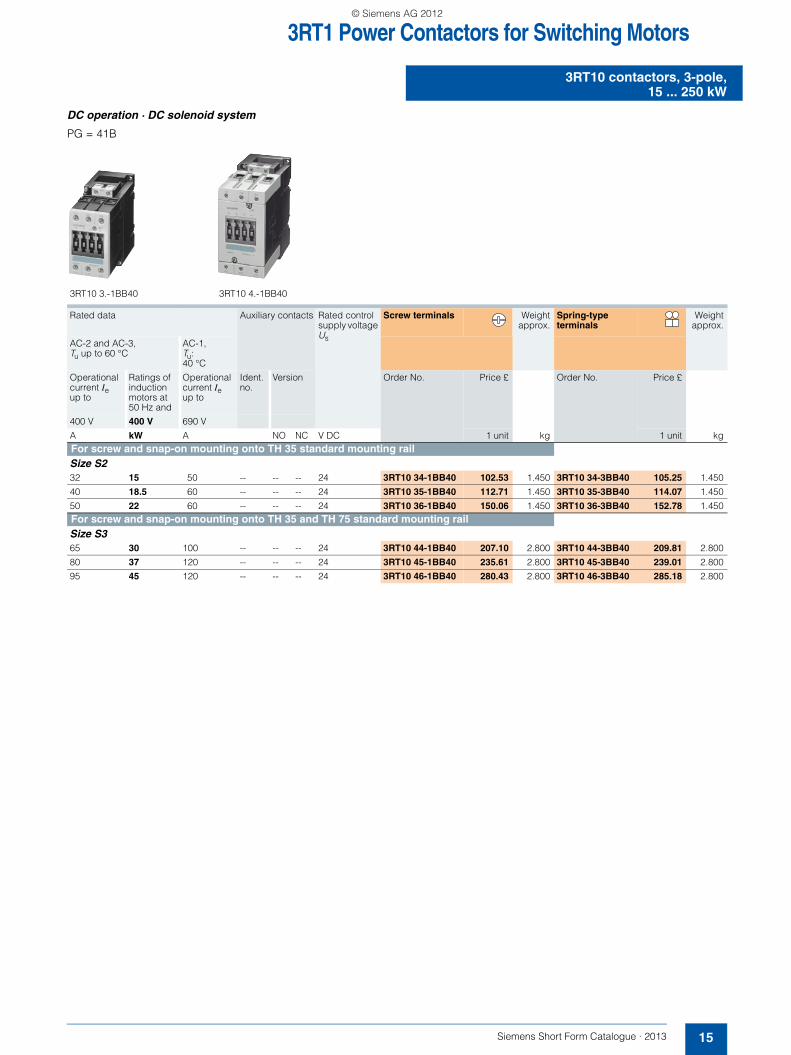
3RT1 Power Contactors for Switching Motors
15Siemens Short Form Catalogue · 2013
3RT10 contactors, 3-pole,15 ... 250 kW
DC operation · DC solenoid system
PG = 41B
Rated data Auxiliary contacts Rated control supply voltage Us
Screw terminals Weightapprox.
Spring-type terminals
Weightapprox.
AC-2 and AC-3, Tu up to 60 °C
AC-1, Tu: 40 °C
Operational current Ieup to
Ratings of induction motors at 50 Hz and
Operational current Ie up to
Ident. no.
Version Order No. Price £ Order No. Price £
400 V 400 V 690 V
A kW A NO NC V DC 1 unit kg 1 unit kgFor screw and snap-on mounting onto TH 35 standard mounting railSize S232 15 50 -- -- -- 24 3RT10 34-1BB40 102.53 1.450 3RT10 34-3BB40 105.25 1.450
40 18.5 60 -- -- -- 24 3RT10 35-1BB40 112.71 1.450 3RT10 35-3BB40 114.07 1.450
50 22 60 -- -- -- 24 3RT10 36-1BB40 150.06 1.450 3RT10 36-3BB40 152.78 1.450For screw and snap-on mounting onto TH 35 and TH 75 standard mounting railSize S365 30 100 -- -- -- 24 3RT10 44-1BB40 207.10 2.800 3RT10 44-3BB40 209.81 2.800
80 37 120 -- -- -- 24 3RT10 45-1BB40 235.61 2.800 3RT10 45-3BB40 239.01 2.800
95 45 120 -- -- -- 24 3RT10 46-1BB40 280.43 2.800 3RT10 46-3BB40 285.18 2.800
3RT10 3.-1BB40 3RT10 4.-1BB40
SFC_2012.book Seite 15 Montag, 10. Dezember 2012 8:19 08
© Siemens AG 2012

3RT1 Power Contactors for Switching Motors
Accessoriesfor 3RT1 contactors
16 Siemens Short Form Catalogue · 2013
■ Selection and ordering data
Internal circuit diagrams and positions of terminals on request.
For contactors Auxiliary contacts Screw terminals PriceGroup
Weightapprox.
Spring-type terminals
PriceGroup
Weightapprox.
Ident. No. Version Order No. Price £ Order No. Price £
Type NO NC 1 unit kg 1 unit kg
Auxiliary switch blocks for snapping onto the front acc. to EN 50005Sizes S2 to S12
4-pole auxiliary switch blocks
3RT1. 2 ... 3RT1.7 40 4 -- 3RH19 21-1FA40 7.30 41B 0.075 3RH19 21-2FA40 7.48 41B 0.07531 3 1 3RH19 21-1FA31 7.30 41B 0.075 3RH19 21-2FA31 7.48 41B 0.07522 2 2 3RH19 21-1FA22 7.30 41B 0.075 3RH19 21-2FA22 7.48 41B 0.075
1-pole auxiliary switch blocks acc. to EN 50005 and EN 50012
3RT1. 2 ... 3RT1.7 -- 1 -- 3RH19 21-1CA10 2.42 41B 0.020 3RH19 21-2CA10 2.53 41B 0.020-- -- 1 3RH19 21-1CA01 2.42 41B 0.020 3RH19 21-2CA01 2.53 41B 0.020
Laterally mountable auxiliary switch blocks acc. to EN 50005Sizes S2 to S12
First laterally mountable auxil-iary switch blocks (right or left), 2-pole
3RT1. 2 ... 3RT1.7 -- 2 -- 3RH19 21-1EA20 6.44 41B 0.050 3RH19 21-2EA20 6.56 41B 0.050-- 1 1 3RH19 21-1EA11 6.44 41B 0.050 ---- -- 2 3RH19 21-1EA02 6.44 41B 0.050 3RH19 21-2EA02 6.56 41B 0.050
Size S3 to S12Second laterally mountable aux-iliary switch blocks (right or left), 2-pole
3RT1. 4 ... 3RT1.7 -- 2 -- 3RH19 21-1KA20 6.44 41B 0.050 3RH19 21-2KA20 7.60 41B 0.050-- 1 1 3RH19 21-1KA11 6.44 41B 0.050 ---- -- 2 3RH19 21-1KA02 6.44 41B 0.050 3RH19 21-2KA02 7.60 41B 0.050
3RH19 21-1F.. 3RH19 21-1CA.. 3RH19 21-1EA..
SFC_2012.book Seite 16 Montag, 10. Dezember 2012 8:19 08
© Siemens AG 2012

3RH2 Contactor Relays
17Siemens Short Form Catalogue · 2013
3RH2 contactor relays,4- and 8-pole
■ Selection and ordering data
AC and DC operation, Size S00
PG = 41A
■ Selection and ordering data
PG = 41B
3RH21 22-1A. .0 3RH21 22 -2A..0.
Rated operational current Ie/AC-15/AC-14 at 230 V
Contacts Rated control supply voltage Us
Screw terminals Weightapprox.
Spring-type terminals
Weightapprox.Ident.
No.Version
Order No. Price £ Order No. Price £
A NO NC V 1 unit kg 1 unit kg
For screw and snap-on mounting onto TH 35 standard mounting railAC operation
AC 50/60 Hz
10 40E 4 -- 24 3RH21 40-1AB00 18.65 0.220 3RH21 40-2AB00 19.28 0.240110 3RH21 40-1AF00 18.65 0.220 3RH21 40-2AF00 19.28 0.240230 3RH21 40-1AP00 18.65 0.220 3RH21 40-2AP00 19.28 0.240
31E 3 1 24 3RH21 31-1AB00 18.65 0.220 3RH21 31-2AB00 19.28 0.240110 3RH21 31-1AF00 18.65 0.220 3RH21 31-2AF00 19.28 0.240230 3RH21 31-1AP00 18.65 0.220 3RH21 31-2AP00 19.28 0.240
22E 2 2 24 3RH21 22-1AB00 18.65 0.220 3RH21 22-2AB00 19.28 0.240110 3RH21 22-1AF00 18.65 0.220 3RH21 22-2AF00 19.28 0.240230 3RH21 22-1AP00 18.65 0.220 3RH21 22-2AP00 19.28 0.240
DC operation · DC solenoid systemDC
10 40E 4 -- 24 3RH21 40-1BB40 21.78 0.280 3RH21 40-2BB40 22.41 0.300220 3RH21 40-1BM40 21.78 0.280 3RH21 40-2BM40 22.41 0.300
31E 3 1 24 3RH21 31-1BB40 21.78 0.280 3RH21 31-2BB40 22.41 0.300220 3RH21 31-1BM40 21.78 0.280 3RH21 31-2BM40 22.41 0.300
22E 2 2 24 3RH21 22-1BB40 21.78 0.280 3RH21 22-2BB40 22.41 0.300220 3RH21 22-1BM40 21.78 0.280 3RH21 22-2BM40 22.41 0.300
Accessories for 3RH2 contactor relays,4- and 8-pole
For contactors/ contactor relays
Contactor with AS block
Auxiliary contacts Screw terminals Weightapprox.
Spring-type terminals
Weightapprox.
Ident. No. Version
Order No. Price £ Order No. Price £
Type NO NC 1 unit kg 1 unit kg
Auxiliary switch blocks for snapping onto the front acc. to EN 50011Size S00For assembling contactor relays with 8 contacts
3RH21 40, 3RH24 40, Ident. No. 40E
80E 4 -- 3RH29 11-1GA40 8.89 0.051 3RH29 11-2GA40 9.23 0.049
71E 3 1 3RH29 11-1GA31 8.89 0.044 3RH29 11-2GA31 9.23 0.049
62E 2 2 3RH29 11-1GA22 8.89 0.044 3RH29 11-2GA22 9.23 0.049
53E 1 3 3RH29 11-1GA13 8.89 0.044 3RH29 11-2GA13 9.23 0.049
44E -- 42) 3RH29 11-1GA04 8.89 0.044 3RH29 11-2GA04 9.23 0.050
SFC_2012.book Seite 17 Montag, 10. Dezember 2012 8:19 08
© Siemens AG 2012

3RV29 Infeed System
3RV29 infeed system
18 Siemens Short Form Catalogue · 2013
■ Overview
The 3RV29 infeed system is a convenient means of energy supply and distribution for a group of several motor starter protectors or complete load feeders with a screw or spring-type connection in sizes S00 and S0 (exception: this system cannot be used for the 3RV21, 3RV27 and 3RV28 motor starter protectors).
The system is based on a basic module complete with a lateral incoming unit (three-phase busbar with infeed). This infeed with spring-type terminals is mounted on the right or left depending on the version and can be supplied with a maximum conductor cross-section of 25 mm2 (with end sleeve). A basic module has two sockets onto each of which a motor starter protector can be snapped.
Expansion modules are available for extending the system (three-phase busbars for system expansion). The individual modules are connected through an expansion plug.
The electrical connection between the three-phase busbars and the motor starter protectors is implemented through plug-in connectors. The complete system can be mounted on a TH 35 standard mounting rail to IEC 60715 and can be expanded as required up to a maximum current carrying capacity of 63 A.
The system is mounted extremely quickly and easily thanks to the simple plug-in technique. Thanks to the lateral infeed, the system also saves space in the control cabinet. The additional overall height required for the infeed unit is only 30 mm. The alternative infeed possibilities on each side offer a high degree of flexibility for configuring the control cabinet: Infeed on left-hand or right-hand side as well as infeed on one side and out-feed on the other side to supply further loads are all possible. A terminal block with spring-type connections in combination with a standard mounting rail enables the integration of not only SIRIUS motor starter protectors but also single-phase, 2-phase and 3-phase components such as 5SY miniature circuit breakers or SIRIUS relay components.
The 3RV29 infeed system is IEC-approved up to 500 V and UL-approved for the assembly of "Self-Protected Combination Motor Controllers" (Type E Starters) as well as Type F Starters (Type E Starters + contactor).
3RV29 infeed system
NS
B0_
0207
8
123a
456
3b 7
1
2
3a
4
5
6
7
3b
5
3-phase busbar with infeed3-phase busbar for system expansionExpansion plug Extra-wide expansion plug
End coverPlug-in connectorContactor baseTerminal block
SFC_2012.book Seite 18 Montag, 10. Dezember 2012 8:19 08
© Siemens AG 2012

3RV29 Infeed System
19Siemens Short Form Catalogue · 2013
3RV29 infeed system
$ Three-phase busbars with infeed
A three-phase busbar with infeed unit is required for connecting the energy supply. This module comprises one infeed module and 2 sockets which each accept one motor starter protector. A choice of two versions with infeed on the left or right is available. The infeed is connected using spring-type terminals. The spring-type terminals permit conductor cross-sections of up to 25 mm2 with end sleeves. An end cover is supplied with each module.
% Three-phase busbars for system expansion
The three-phase busbars for system expansion allow the system to be expanded. There is a choice of modules with 2 or 3 sock-ets. The system can be expanded as required up to a maximum current carrying capacity of 63 A. An expansion plug is supplied with each module.
&a Expansion plug
The expansion plug is used for electrical connection of adjacent three-phase busbars. The current carrying capacity of this plug equals 63 A. One expansion plug is supplied with each three-phase busbar for system expansion. Additional expansion plugs are therefore only required as spare parts.
&b Extra-wide expansion plug
The wide expansion plug makes the electrical connection between two three-phase busbars, thus performing the same function as the 3RV29 17-5BA00 expansion plug; the electrical characteristics (e.g. a current carrying capacity of 63 A) are identical.
The 3RV29 17-5E expansion plug is 10 mm wider than the 3RV29 17-5BA00 expansion plug, hence in the plugged state there is a distance of 10 mm between the connected three-phase busbars. This distance can be used to lay the auxiliary current and control current wiring ("wiring duct"). The motor starter protector and contactor can be wired from underneath, which means that the complete cable duct above the system can be omitted.
( End cover
The end cover is used to cover the three-phase busbar at the open end of the system. This cover is therefore only required once for each system. An end cover is supplied with each three-phase busbar system with infeed. Further end covers are there-fore only required as spare parts.
) Plug-in connector
The plug-in connector is used for the electrical connection between the three-phase busbar and the 3RV2 motor starter protector. These plug-in connectors are available in versions for screw or spring-type terminals.
* Contactor base
Load feeders can be assembled in the system using the contac-tor base. The contactor bases are suitable for contactors sizes S00 and S0 with spring-type and screw terminals and are simply snapped onto the three-phase busbars. Direct-on-line starters and reversing starters are possible. One contactor base is required for direct-on-line starters and two are required for reversing starters.
To assemble load feeders for reversing starters, the contactor bases can be arranged alongside each other (90 mm overall width). In this case the mechanical interlocking of the contactors is possible. The contactor bases are also suitable for soft start-ers size S00 and S0 with screw connection.
The infeed system is designed for mounting on a 35 mm stan-dard mounting rail with 7.5 mm overall depth. This standard mounting rail gives the contactor base a stable mounting sur-face to sit on. If standard mounting rails with a depth of 15 mm are used, the spacer connected to the bottom of the contactor base must be knocked out and plugged into the mating piece that is also on the underside. Then the contactor base also has a stable mounting surface. When standard mounting rails with a depth of 7.5 mm are used, the spacer has no function and can be removed.
The link modules are used for direct start load feeders, in which case the use of a contactor base is not absolutely necessary. Motor starter protector and contactor assemblies can then be directly snapped onto the sockets of the three-phase busbars. For feeders of size S00 and S0, the corresponding 3RA19 21-1...., 3RA29 11-2...., 3RA29 21-1.... or 3RA29 21-2.... link modules should generally be used.
+ Terminal block
The 3RV29 17-5D terminal block enables the integration of not only SIRIUS motor starter protectors but also single-phase, 2-phase and 3-phase components. Using the terminal block the 3 phases can be fed out of the system; which means that single-phase loads can also be integrated in the system. The terminal block is plugged into the slot of the expansion plug and thus en-ables outfeeding from the middle or end of the infeed system. The terminal block can be rotated through 180° and be locked to the support modules of the infeed system. The 3RV19 17-7B 45 mm standard mounting rail for screwing onto the support plate is available in addition in order to be able to plug the single-phase, 2-phase and 3-phase components onto the infeed system.
SFC_2012.book Seite 19 Montag, 10. Dezember 2012 8:19 08
© Siemens AG 2012

3RV29 Infeed System
3RV29 infeed system
20 Siemens Short Form Catalogue · 2013
■ Selection and ordering data
1) I > 14 A, note derating; see the system manual "SIRIUS Innovations", Chapter "Motor Starter Protectors".
2) I > 16 A, note derating; see the system manual "SIRIUS Innovations", Chapter "Motor Starter Protectors".
Type Version For 3RV20 motor starter protectors
Order No. Price £ PG Weightapprox.
Size 1 unit kg
Three-phase busbars with infeed
3RV29 17-1A
3-phase busbars with infeed incl. 3RV29 17-6A end cover
For 2 motor starter protectors with screw connection or spring-type terminals
• With infeed on the left S00, S0 3RV29 17-1A 12.43 41E 0.369
• With infeed on the right S00, S0 3RV29 17-1E 12.43 41E 0.369
Three-phase busbars for system expansion
3RV29 17-4A
3-phase busbarsincl. 3RV29 17-5BA00 expansion plug
For motor starter protectors with screw connection or spring-type terminals
• For 2 motor starter protectors S00, S0 3RV29 17-4A 7.54 41E 0.229
• For 3 motor starter protectors S00, S0 3RV29 17-4B 9.98 41E 0.328
Plug-in connectors
3RV29 17-5AA00
Plug-in connectors to make contact with the motor starter protectors
• For spring-type terminals Spring-typeterminals
- Single-unit packaging S001) 3RV29 17-5AA00 2.17 41E 0.046S02) 3RV29 27-5AA00 2.17 41E 0.059
- Multi-unit packaging (10 units)
S001) 3RV29 17-5A 1.77 41E 0.046S02) 3RV29 27-5A 1.77 41E 0.059
3RV29 17-5CA00
• For screw terminals Screw terminals
- Single-unit packaging S001) 3RV29 17-5CA00 2.17 41E 0.029S02) 3RV19 27-5AA00 2.44 41E 0.040
- Multi-unit packaging (10 units)
S001) 3RV29 17-5C 1.77 41E 0.029S02) 3RV19 27-5A 1.96 41E 0.036
Type Version For contactors Order No. Price £ PG Weightapprox.
Size 1 unit kg
Contactor bases
3RV29 27-7AA00
Contactor basesfor mounting direct-on-line or reversing starters
Single-unit packaging S00 3RV29 17-7AA00 1.83 41E 0.050
S0 3RV29 27-7AA00 1.83 41E 0.050
SFC_2012.book Seite 20 Montag, 10. Dezember 2012 8:19 08
© Siemens AG 2012
3RV29 Infeed System
21Siemens Short Form Catalogue · 2013
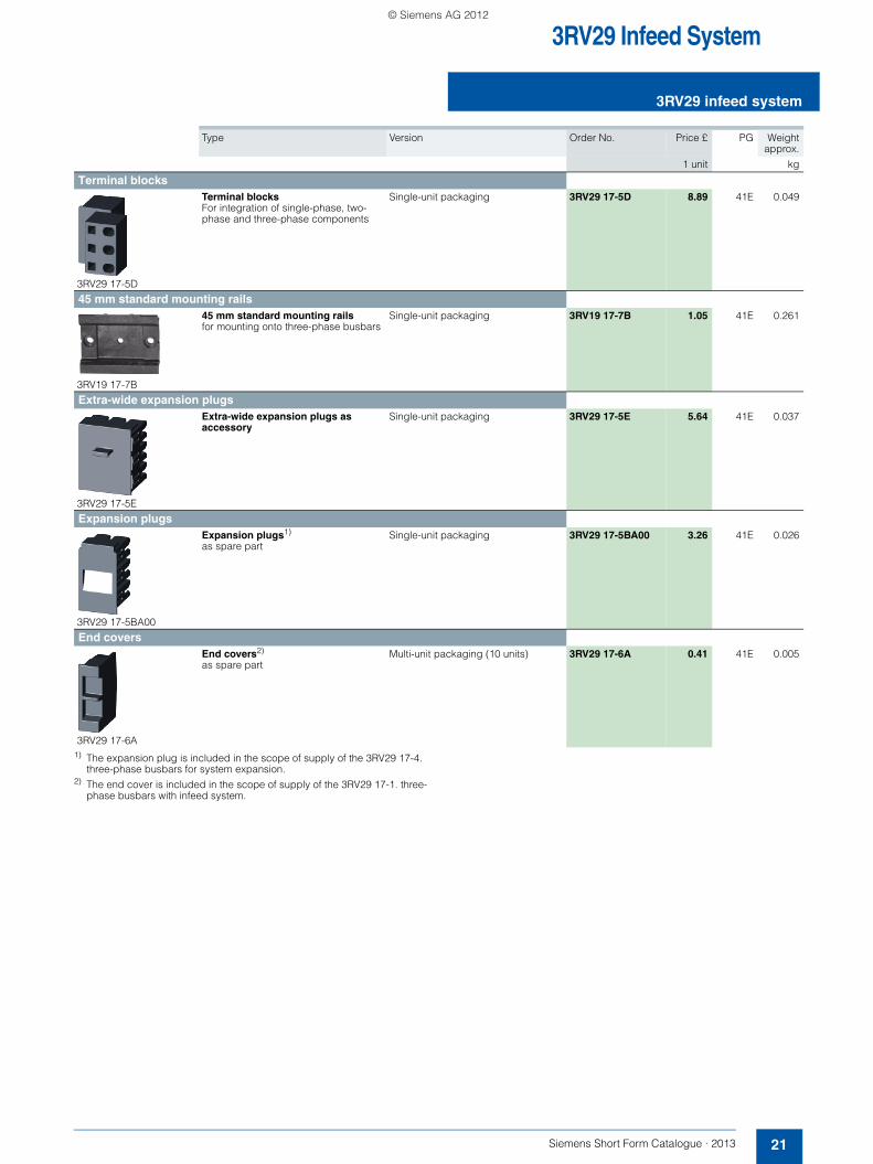
3RV29 infeed system
1) The expansion plug is included in the scope of supply of the 3RV29 17-4. three-phase busbars for system expansion.
2) The end cover is included in the scope of supply of the 3RV29 17-1. three-phase busbars with infeed system.
Type Version Order No. Price £ PG Weightapprox.
1 unit kg
Terminal blocks
3RV29 17-5D
Terminal blocks For integration of single-phase, two-phase and three-phase components
Single-unit packaging 3RV29 17-5D 8.89 41E 0.049
45 mm standard mounting rails
3RV19 17-7B
45 mm standard mounting rails for mounting onto three-phase busbars
Single-unit packaging 3RV19 17-7B 1.05 41E 0.261
Extra-wide expansion plugs
3RV29 17-5E
Extra-wide expansion plugs as accessory
Single-unit packaging 3RV29 17-5E 5.64 41E 0.037
Expansion plugs
3RV29 17-5BA00
Expansion plugs1)
as spare partSingle-unit packaging 3RV29 17-5BA00 3.26 41E 0.026
End covers
3RV29 17-6A
End covers2)
as spare partMulti-unit packaging (10 units) 3RV29 17-6A 0.41 41E 0.005
SFC_2012.book Seite 21 Montag, 10. Dezember 2012 8:19 08
© Siemens AG 2012

3RA6 Fuseless Compact Starters
General data
22 Siemens Short Form Catalogue · 2013
■ Overview
3RA6 fuseless compact starters and infeed system for 3RA6
3RA62 reversing starter
Integrated functionality
The SIRIUS 3RA6 compact starters are a generation of innova-tive load feeders with the integrated functionality of a motor starter protector, contactor and solid-state overload relay. In addition, various functions of optional mountable accessories (e. g. auxiliary switches, surge suppressors) are already inte-grated in the SIRIUS compact starter.
Application
The SIRIUS compact starters can be used wherever standard induction motors up to 32 A (approx. 15 kW/400 V) are directly started.
Approvals according to IEC, UL and CSA standards have been issued for the compact starters.
Low equipment variance
Thanks to wide setting ranges for the rated current and wide voltage ranges, the equipment variance is greatly reduced compared to conventional load feeders.
Very high operational reliability
Through the high short-circuit breaking capacity and defined shut-down when the end of service life is reached means that the SIRIUS compact starter achieves a very high level of operational reliability that would otherwise have only been possible with considerable additional outlay. This sets it apart from devices with similar functionality.
Safe disconnection
The auxiliary switches of the 3RA6 compact starters are de-signed as mirror contacts. It is thus possible to use the devices for safe disconnection, e. g. emergency-stops, up to Category 2 (EN 954-1) and together with other redundancy switching devices up to Category 3 or 4.
Communications integration through AS-Interface
To enable communications integration through AS-Interface there is an AS-i add-on module available in several versions for mounting instead of the control circuit terminals on the SIRIUS compact starter.
The design of the AS-i add-on module permits a group of up to 62 feeders with a total of four cables to be connected to the control system. This reduces wiring work considerably compared to the parallel wiring method.
Communications integration using IO-Link
Up to 4 compact starters in IO-Link version (reversing and direct-on-line starters) can be connected together and conve-niently linked to the IO-Link master through a standardized IO-Link connection. The SIRIUS 4SI solid-state module is used for example as an IO-Link master for connection to the SIMATIC ET 200S distributed I/O system.
The IO-Link connection enables a high density of information in the local range.
The diagnostics data of the process collected by the 3RA6 com-pact starter, e. g. short-circuit, end of service life, limit position etc., are not only indicated on the compact starter itself but also transmitted to the higher-level control system through IO-Link.
Thanks to the optionally available operator panel, which can be installed in the control cabinet door, it is easy to control the 3RA6 compact starter with IO-Link from the control cabinet door.
Permanent wiring/easy replacement
Using the SIRIUS infeed system for 3RA6 (see page 24) it is possible to carry out the wiring in advance without a compact starter needing to be connected.
A compact starter is very easily replaced simply by pulling it out of the device without disconnecting the wiring.
Even with screw connections or mounting on a standard mount-ing rail there is no need to disconnect any wiring (on account of the removable main and control circuit terminals) in order to replace a compact starter.
Consistent solution from the infeed to the motor feeder
The SIRIUS infeed system for 3RA6 with integrated PE bar is offered as a user-friendly possibility of feeding in summation currents up to 100 A with a maximum conductor cross-section of 70 mm² and connecting the motor cable directly without additional intermediate terminals.
Screw and spring-type connections
The SIRIUS compact starters and the infeed system for 3RA6 are available with screw and spring-type connections.
System configurator for engineering
A free system configurator is available to reduce further the amount of engineering work for selecting the required compact starters and matching infeed.
Types of infeed for the 3RA6 fuseless compact starters
On the whole four different infeed possibilities are available:• Parallel wiring• Use of three-phase busbars (combination with SIRIUS motor
starter protectors and SIRIUS contactors possible)• 8US busbar adapters• SIRIUS infeed system for 3RA6 (see page 24)
SFC_2012.book Seite 22 Montag, 10. Dezember 2012 8:19 08
© Siemens AG 2012

3RA6 Fuseless Compact Starters
23Siemens Short Form Catalogue · 2013
3RA61 direct-on-line starters
■ Selection and ordering data
Online-Configurator, see www.siemens.com/sirius/configurators.
■ Selection and ordering data
Online-Configurator, see www.siemens.com/sirius/configurators.1) Selection depends on the concrete start-up and rated data of the
protected motor.
Further versions available on request.
3RA61 20-1CB32
Direct start A set of 3RA69 40-0A adapters is required for screw mounting, see catalogue IC 10.
Standard induction motor 4-pole at 400 V AC1)
Setting range for solid-state overload release
Rated control supply voltage Us
Screw terminals PriceGroup
Weightapprox.
Standard output P
Configurator
Order No. Price £
kW A V AC/DC 1 unit kg
According to IEC/EN 60947-6-2 no welding of contactor contacts at Iq = 53 kA at 400 V0.09 0.1 ...0.4 24 3RA61 20-1AB32 98.86 42F 1.355
110 ... 240 3RA61 20-1AP32 98.86 42F 1.355
0.37 0.32 ... 1.25 24 3RA61 20-1BB32 104.58 42F 1.355110 ... 240 3RA61 20-1BP32 104.58 42F 1.355
1.5 1 ... 4 24 3RA61 20-1CB32 112.75 42F 1.355110 ... 240 3RA61 20-1CP32 112.75 42F 1.355
5.5 3 ... 12 24 3RA61 20-1DB32 118.47 42F 1.379110 ... 240 3RA61 20-1DP32 118.47 42F 1.379
15 8 ... 32 24 3RA61 20-1EB32 177.29 42F 1.396110 ... 240 3RA61 20-1EP32 177.29 42F 1.396
NSB0_01946
3RA62 reversing starters
3RA62 50-1CB32
Reversing duty Two sets of 3RA69 40-0A adapters are required for screw mounting,see catalogue IC 10.
Standard induction motor 4-pole at 400 V AC1)
Setting rangefor solid-state overload release
Rated control supply voltage Us
Screw terminals PriceGroup
Weightapprox.
Standard output P
Configurator
Order No. Price £
kW A V AC/DC 1 unit kg
According to IEC/EN 60947-6-2 no welding of contactor contacts at Iq = 53 kA at 400 V0.09 0.1 ...0.4 24 3RA62 50-1AB32 177.29 42F 2.341
110 ... 240 3RA62 50-1AP32 177.29 42F 2.341
0.37 0.32 ... 1.25 24 3RA62 50-1BB32 178.92 42F 2.341110 ... 240 3RA62 50-1BP32 178.92 42F 2.341
1.5 1 ... 4 24 3RA62 50-1CB32 190.36 42F 2.341110 ... 240 3RA62 50-1CP32 190.36 42F 2.341
5.5 3 ... 12 24 3RA62 50-1DB32 210.79 42F 2.357110 ... 240 3RA62 50-1DP32 210.79 42F 2.357
15 8 ... 32 24 3RA62 50-1EB32 272.88 42F 2.405110 ... 240 3RA62 50-1EP32 272.88 42F 2.405
NSB0_01947
SFC_2012.book Seite 23 Montag, 10. Dezember 2012 8:19 08
© Siemens AG 2012

3RA6 Fuseless Compact Starters
Infeed systems for 3RA6
24 Siemens Short Form Catalogue · 2013
■ Overview
The infeed system for 3RA6 compact starters enables far less wiring in the main circuit and, thanks to the easy exchangeability of the compact starters, reduces the usual downtimes for maintenance work during the plant's operating phase.
The infeed system provides the possibility of completely prewiring the main circuit without a compact starter needing to be connected at the same time. As the result of the removable terminals in the main circuit, compact starters can be integrated in an infeed system in easy manner (without the use of tools).
In addition, the integrated PE bar means it is optionally possible to connect the motor cable directly to the infeed system without additional intermediate terminals. The infeed system for 3RA6 compact starters is designed for summation currents up to 100 A with a maximum 70 mm² conductor cross-section on the feeder terminal block.
The infeed system can be mounted on a standard mounting rail, a 60 mm busbar system or flat surfaces.
3RA6 infeed system
NS
B0_
0187
8
1
4
5
6
2
3
12
11
7
9
8
10
Feeder terminal
Three-socket expansion module
Two-socket expansion module
Expansion plug
PE infeed
PE expansion plug
1
2
3
6
4
5
PE pick-off
Connecting wedges
End cover
45 mm adapter for SIRIUS motor starter protector size S0
3RA61 direct-on-line starter
3RA62 reversing starter
7
8
9
12
10
11
SFC_2012.book Seite 24 Montag, 10. Dezember 2012 8:19 08
© Siemens AG 2012

3RA6 Fuseless Compact Starters
25Siemens Short Form Catalogue · 2013
Infeed systems for 3RA6
■ Selection and ordering data
Online-Configurator, see www.siemens.com/sirius/configurators.
Type Screw terminals PriceGroup
Weightapprox.
Configurator
Order No. Price £1 unit kg
3-phase infeeds and expansion modules
3RA68 12-8AB
Infeeds 25/35 mm2 on left
with permanently fitted 3-socket expansion module on outgoing side and integrated PE bar
Expansion module with 3 sockets for 3 direct-on-line starters or 1 direct-on-line starter and 1 reversing starter
3RA68 12-8AB 56.37 42F 0.957
3RA68 13-8AB
Infeeds 50/70 mm2 on left
with permanently fitted 3-socket expansion module on outgoing side and integrated PE bar
Expansion module with 3 sockets for 3 direct-on-line starters or 1 direct-on-line starter and 1 reversing starter suitable for UL duty according to UL 508 Type E
3RA68 13-8AB 70.18 42F 1.146
Expansion modules
3RA68 22-0AB
2-socket expansion modules
and integrated PE bar with 2 sockets for 2 direct-on-line starters or 1 reversing starter
Expansion plug and 2 connecting plates are included in the scope of supply.
3RA68 22-0AB 28.68 42F 0.505
3RA68 23-0AB
3-socket expansion modules
and integrated PE bar with 3 sockets for 3 direct-on-line starters or 1 direct-on-line starter and 1 reversing starter
Expansion plug and 2 connecting plates are included in the scope of supply.
3RA68 23-0AB 40.69 42F 0.717
Accessories for infeed systems for 3RA6PE infeeds 25/35 mm2 3RA68 60-6AB 6.86 42F 0.060
PE pick-offs 6/10 mm2 3RA68 70-4AB 2.78 42F 0.019
3RA68 90-0EA
PE expansion plugs 3RA68 90-0EA 2.45 42F 0.008
3RA68 80-2AB
IP 20 terminal covers for infeeds with screw connection 25/35 mm² (3RA68 12-8AB)
(2 units per pack)
3RA68 80-2AB 4.90 42F 0.023
3RA68 80-3AB
IP 20 terminal covers for infeeds with screw connection 50/70 mm² (3RA68 13-8AB)
(2 units per pack)
3RA68 80-3AB 5.23 42F 0.040
3RA68 60-6AB
3RA68 70-4AB
SFC_2012.book Seite 25 Montag, 10. Dezember 2012 8:19 08
© Siemens AG 2012

3RW Soft Starters
3RW30for standard applications
26 Siemens Short Form Catalogue · 2013
■ Overview
The SIRIUS 3RW30 soft starters reduce the motor voltage through variable phase control and increase it in ramp-like mode from a selectable starting voltage up to mains voltage. During starting, these devices limit the torque as well as the current and prevent the shocks which arise during direct starts or wye-delta starts. In this way, mechanical loads and mains voltage dips can be reliably reduced.
Soft starting reduces the stress on the connected equipment and results in lower wear and therefore longer periods of trouble-free production. The selectable start value means that the soft-starters can be adjusted individually to the requirements of the application in question and unlike wye-delta starters are not restricted to two-stage starting with fixed voltage ratios.
The SIRIUS 3RW30 soft starters are characterized above all by their small space requirements. Integrated bypass contacts
mean that no power loss has to be taken into the bargain at the power semiconductors (thyristors) after the motor has started up. This cuts down on heat losses, enabling a more compact design and making external bypass circuits superfluous.
Various versions of the SIRIUS 3RW30 soft starters are available:• Standard version for fixed-speed three-phase motors, sizes
S00, S0, S2 and S3, with integrated bypass contact system• Version for fixed-speed three-phase motors in a 22.5 mm
enclosure without bypass.
Soft starters rated up to 55 kW (at 400 V) for standard applica-tions in three-phase networks are available. Extremely small sizes, low power losses and simple start-up are just three of the many advantages of this soft starter.
■ Selection and ordering data
Online-Configurator, see www.siemens.com/sirius/configurators.
Note:
Selection of the soft starter depends on the rated motor current. The SIRIUS 3RW30/ 3RW40 solid-state soft starters are de-signed for easy starting conditions. ILoad < 10 x IMotor. In the
event of deviating conditions or increased switching frequency, it may be necessary to choose a larger device. Siemens recom-mends the use of the selection and simulation program Win-Soft Starter. For infomation about rated currents for ambient temper-atures > 40 °C, see www.siemens.com/industry/OnlineSupport.
3RW30 1. 3RW30 2. 3RW30 3. 3RW30 4.
Rated operational voltage Ue
At ambient temperature 40 °C Size Rated control supply voltage Us
Screw terminals PriceGroup
Weightapprox.
Rated operational current Ie Rated power of induction motors for rated operational voltage Ue
Configurator
230 V 400 V Order No. Price £
V A kW kW V AC/DC 1 unit kg
Inline circuit, rated operational voltage 200 ... 480 V200 ... 480 3.6 0.75 1.5 S00 24 3RW30 13-1BB04 85.78 42G 0.580
110 ... 230 3RW30 13-1BB14 85.78 42G 0.580
6.5 1.5 3 S00 24 3RW30 14-1BB04 99.24 42G 0.580110 ... 230 3RW30 14-1BB14 99.24 42G 0.580
9 2.2 4 S00 24 3RW30 16-1BB04 114.38 42G 0.580110 ... 230 3RW30 16-1BB14 114.38 42G 0.580
12.5 3 5.5 S00 24 3RW30 17-1BB04 127.83 42G 0.580110 ... 230 3RW30 17-1BB14 127.83 42G 0.580
17.6 4 7.5 S00 24 3RW30 18-1BB04 147.18 42G 0.690110 ... 230 3RW30 18-1BB14 147.18 42G 0.690
25 5.5 11 S0 24 3RW30 26-1BB04 171.56 42G 0.690110 ... 230 3RW30 26-1BB14 171.56 42G 0.690
32 7.5 15 S0 24 3RW30 27-1BB04 200.16 42G 0.690110 ... 230 3RW30 27-1BB14 200.16 42G 0.690
38 11 18.5 S0 24 3RW30 28-1BB04 247.25 42G 0.690110 ... 230 3RW30 28-1BB14 247.25 42G 0.690
45 11 22 S2 24 3RW30 36-1BB04 303.60 42G 1.200110 ... 230 3RW30 36-1BB14 303.60 42G 1.200
63 18.5 30 S2 24 3RW30 37-1BB04 370.04 42G 1.200110 ... 230 3RW30 37-1BB14 370.04 42G 1.200
72 22 37 S2 24 3RW30 38-1BB04 438.16 42G 1.200110 ... 230 3RW30 38-1BB14 438.16 42G 1.200
80 22 45 S3 24 3RW30 46-1BB04 503.76 42G 1.700110 ... 230 3RW30 46-1BB14 503.76 42G 1.700
106 30 55 S3 24 3RW30 47-1BB04 561.79 42G 1.700110 ... 230 3RW30 47-1BB14 561.79 42G 1.700
SFC_2012.book Seite 26 Montag, 10. Dezember 2012 8:19 08
© Siemens AG 2012

3RW Soft Starters
27Siemens Short Form Catalogue · 2013
3RW40for standard applications
■ Overview
SIRIUS 3RW40 soft starters offer all the same advantages as the 3RW30 soft starters. This also applies to the integrated bypass con-tact system. At the same time they come with additional functions, e. g. solid-state motor overload and intrinsic device protection and adjustable current limiting, optional thermistor motor protec-tion (up to size S3), integrated remote RESET (up to size S3), as well as a two-phase control method (Polarity Balancing) that is unique in this performance range.
SIRIUS 3RW40 soft starters are part of the SIRIUS modular system. This results in advantages such as identical sizes and a uniform connection method. Thanks to their particularly compact design, SIRIUS 3RW40 soft starters are only half as big as comparable wye-delta starters. Hence they can be mounted in minimum
space in the control cabinet. Configuring and mounting are carried out quickly and easily thanks to the 3-wire connection.
SIRIUS 3RW40 for three-phase motors
Soft starters rated up to 250 kW (at 400 V) for standard applications in three-phase networks. Extremely small sizes, low power losses and simple commissioning are just three of the many advantages of the SIRIUS 3RW40 soft starters.
"Increased safety" type of protection EEx e according to ATEX directive 94/9/EC
The SIRIUS 3RW40 soft starters size S6, S10 and S12 are suitable for starting explosion-proof motors with "increased safety" type of protection EEx e.
■ Selection and ordering data
For normal starting (CLASS 10)
Online-Configurator, see www.siemens.com/sirius/configurators. See note on page 26.
Rated operational voltage Ue
At ambient temperature 40 °C At ambient temperature 50 °C
Size Rated control supply voltage Us
Screw terminals PriceGroup
Weightapprox.
Rated operational current Ie
Rated power of induction motors for rated operational voltage Ue
Rated operational current Ie
Configurator
Order No. Price £
400 V
V A kW A V AC/DC 1 unit kg
Inline circuit, rated operational voltage 200 ... 480 V200 ... 480 12.5 5.5 11 S0 24 3RW40 24-1BB04 190.07 42G 0.770
110 ... 230 3RW40 24-1BB14 190.07 42G 0.770
25 11 23 S0 24 3RW40 26-1BB04 224.55 42G 0.770110 ... 230 3RW40 26-1BB14 224.55 42G 0.770
32 15 29 S0 24 3RW40 27-1BB04 266.60 42G 0.770110 ... 230 3RW40 27-1BB14 266.60 42G 0.770
38 18.5 34 S0 24 3RW40 28-1BB04 319.58 42G 0.770110 ... 230 3RW40 28-1BB14 319.58 42G 0.770
45 22 42 S2 24 3RW40 36-1BB04 380.97 42G 1.350110 ... 230 3RW40 36-1BB14 380.97 42G 1.350
63 30 58 S2 24 3RW40 37-1BB04 451.62 42G 1.350110 ... 230 3RW40 37-1BB14 451.62 42G 1.350
72 37 62 S2 24 3RW40 38-1BB04 523.94 42G 1.350110 ... 230 3RW40 38-1BB14 523.94 42G 1.350
80 45 73 S3 24 3RW40 46-1BB04 590.38 42G 1.900110 ... 230 3RW40 46-1BB14 590.38 42G 1.900
106 55 98 S3 24 3RW40 47-1BB04 643.37 42G 1.900110 ... 230 3RW40 47-1BB14 643.37 42G 1.900
Inline circuit. rated operational voltage 200 ... 460 V200 ... 460 134 75 117 S6 110 3RW40 55-6BB34 681.21 42G 5.700
230 3RW40 55-6BB44 681.21 42G 5.700
162 90 145 S6 110 3RW40 56-6BB34 849.41 42G 5.700230 3RW40 56-6BB44 849.41 42G 5.700
230 132 205 S12 110 3RW40 73-6BB34 950.33 42G 7.000230 3RW40 73-6BB44 950.33 42G 7.000
280 160 248 S12 110 3RW40 74-6BB34 1 068.07 42G 7.000230 3RW40 74-6BB44 1 068.07 42G 7.000
356 200 315 S12 110 3RW40 75-6BB34 1244.68 42G 7.000230 3RW40 75-6BB44 1 244.68 42G 7.000
432 250 385 S12 110 3RW40 76-6BB34 1 648.36 42G 7.000230 3RW40 76-6BB44 1 648.36 42G 7.000
3RW40 2. 3RW40 3. 3RW40 4. 3RW40 5. 3RW40 7.
SFC_2012.book Seite 27 Montag, 10. Dezember 2012 8:19 08
© Siemens AG 2012
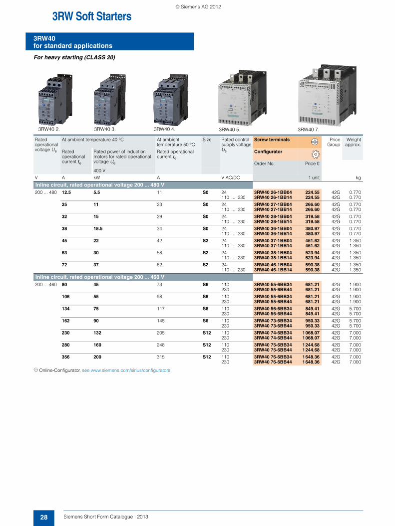
3RW Soft Starters
3RW40for standard applications
28 Siemens Short Form Catalogue · 2013
For heavy starting (CLASS 20)
Online-Configurator, see www.siemens.com/sirius/configurators.
Rated operational voltage Ue
At ambient temperature 40 °C At ambient temperature 50 °C
Size Rated control supply voltage Us
Screw terminals PriceGroup
Weightapprox.
Rated operational current Ie
Rated power of induction motors for rated operational voltage Ue
Rated operational current Ie
Configurator
Order No. Price £
400 V
V A kW A V AC/DC 1 unit kg
Inline circuit, rated operational voltage 200 ... 480 V200 ... 480 12.5 5.5 11 S0 24 3RW40 26-1BB04 224.55 42G 0.770
110 ... 230 3RW40 26-1BB14 224.55 42G 0.770
25 11 23 S0 24 3RW40 27-1BB04 266.60 42G 0.770110 ... 230 3RW40 27-1BB14 266.60 42G 0.770
32 15 29 S0 24 3RW40 28-1BB04 319.58 42G 0.770110 ... 230 3RW40 28-1BB14 319.58 42G 0.770
38 18.5 34 S0 24 3RW40 36-1BB04 380.97 42G 0.770110 ... 230 3RW40 36-1BB14 380.97 42G 0.770
45 22 42 S2 24 3RW40 37-1BB04 451.62 42G 1.350110 ... 230 3RW40 37-1BB14 451.62 42G 1.350
63 30 58 S2 24 3RW40 38-1BB04 523.94 42G 1.350110 ... 230 3RW40 38-1BB14 523.94 42G 1.350
72 37 62 S2 24 3RW40 46-1BB04 590.38 42G 1.350110 ... 230 3RW40 46-1BB14 590.38 42G 1.350
Inline circuit. rated operational voltage 200 ... 460 V200 ... 460 80 45 73 S6 110 3RW40 55-6BB34 681.21 42G 1.900
230 3RW40 55-6BB44 681.21 42G 1.900
106 55 98 S6 110 3RW40 55-6BB34 681.21 42G 1.900230 3RW40 55-6BB44 681.21 42G 1.900
134 75 117 S6 110 3RW40 56-6BB34 849.41 42G 5.700230 3RW40 56-6BB44 849.41 42G 5.700
162 90 145 S6 110 3RW40 73-6BB34 950.33 42G 5.700230 3RW40 73-6BB44 950.33 42G 5.700
230 132 205 S12 110 3RW40 74-6BB34 1068.07 42G 7.000230 3RW40 74-6BB44 1068.07 42G 7.000
280 160 248 S12 110 3RW40 75-6BB34 1244.68 42G 7.000230 3RW40 75-6BB44 1244.68 42G 7.000
356 200 315 S12 110 3RW40 76-6BB34 1648.36 42G 7.000230 3RW40 76-6BB44 1648.36 42G 7.000
3RW40 2. 3RW40 3. 3RW40 4. 3RW40 5. 3RW40 7.
SFC_2012.book Seite 28 Montag, 10. Dezember 2012 8:19 08
© Siemens AG 2012
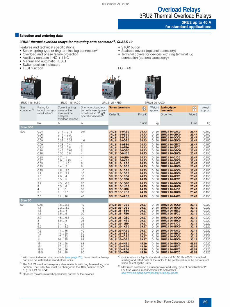
Overload Relays3RU2 Thermal Overload Relays
29Siemens Short Form Catalogue · 2013
3RU2 up to 40 Afor standard applications
■ Selection and ordering data
3RU21 thermal overload relays for mounting onto contactor1), CLASS 10
Features and technical specifications:• Screw, spring-type or ring terminal lug connection2)
• Overload and phase failure protection• Auxiliary contacts 1 NO + 1 NC• Manual and automatic RESET• Switch position indicators• TEST function
• STOP button• Sealable covers (optional accessory)• Terminal covers for devices with ring terminal lug
connection (optional accessory)
PG = 41F
1) With the suitable terminal brackets (see page 28), these overload relays can also be installed as stand-alone units.
2) The 3RU21 overload relays are also available with ring terminal lug con-nection. The Order No. must be changed in the 10th position to "J":e. g. 3RU21 16-0AJ0.
3) Observe maximum rated operational current of the devices.
4) Guide value for 4-pole standard motors at AC 50 Hz 400 V. The actual starting and rated data of the motor to be protected must be considered when selecting the units.
5) Maximum protection by fuse for overload relay, type of coordination "2". For fuse values in connection with contactors see www.siemens.com/industry/OnlineSupport.
Size contactor3)
Rating for induction motor, rated value4)
Current setting value of the inverse-time delayed overload release
Short-circuit protec-tion with fuse, type of coordination "2", gG operational class5)
Screw terminals Weightapprox.
Spring-type terminals
Weightapprox.
Order No. Price £ Order No. Price £
kW A A 1 unit kg 1 unit kg
Size S00S00 0.04 0.11 ... 0.16 0.5 3RU21 16-0AB0 24.73 0.130 3RU21 16-0AC0 25.47 0.150
0.06 0.14 ... 0.2 1 3RU21 16-0BB0 24.73 0.130 3RU21 16-0BC0 25.47 0.1500.06 0.18 ... 0.25 1 3RU21 16-0CB0 24.73 0.130 3RU21 16-0CC0 25.47 0.1500.09 0.22 ... 0.32 1.6 3RU21 16-0DB0 24.73 0.130 3RU21 16-0DC0 25.47 0.150
0.09 0.28 ... 0.4 2 3RU21 16-0EB0 24.73 0.130 3RU21 16-0EC0 25.47 0.1500.12 0.35 ... 0.5 2 3RU21 16-0FB0 24.73 0.130 3RU21 16-0FC0 25.47 0.1500.18 0.45 ... 0.63 2 3RU21 16-0GB0 24.73 0.130 3RU21 16-0GC0 25.47 0.1500.18 0.55 ... 0.8 4 3RU21 16-0HB0 24.73 0.130 3RU21 16-0HC0 25.47 0.150
0.25 0.7 ... 1 4 3RU21 16-0JB0 24.73 0.130 3RU21 16-0JC0 25.47 0.1500.37 0.9 ... 1.25 4 3RU21 16-0KB0 24.73 0.130 3RU21 16-0KC0 25.47 0.1500.55 1.1 ... 1.6 6 3RU21 16-1AB0 24.73 0.130 3RU21 16-1AC0 25.47 0.1500.75 1.4 ... 2 6 3RU21 16-1BB0 24.73 0.130 3RU21 16-1BC0 25.47 0.150
0.75 1.8 ... 2.5 10 3RU21 16-1CB0 24.73 0.130 3RU21 16-1CC0 25.47 0.1501.1 2.2 ... 3.2 10 3RU21 16-1DB0 24.73 0.130 3RU21 16-1DC0 25.47 0.1501.5 2.8 ... 4 16 3RU21 16-1EB0 24.73 0.130 3RU21 16-1EC0 25.47 0.1501.5 3.5 ... 5 20 3RU21 16-1FB0 24.73 0.130 3RU21 16-1FC0 25.47 0.150
2.2 4.5 ... 6.3 20 3RU21 16-1GB0 24.73 0.130 3RU21 16-1GC0 25.47 0.1503 5.5 ... 8 25 3RU21 16-1HB0 24.73 0.130 3RU21 16-1HC0 25.47 0.1504 7 ... 10 35 3RU21 16-1JB0 24.73 0.130 3RU21 16-1JC0 25.47 0.1505.5 9 ... 12.5 35 3RU21 16-1KB0 24.73 0.130 3RU21 16-1KC0 25.47 0.150
7.5 11 ... 16 40 3RU21 16-4AB0 24.73 0.130 3RU21 16-4AC0 25.47 0.150
Size S0S0 0.75 1.8 ... 2.5 10 3RU21 26-1CB0 29.27 0.160 3RU21 26-1CC0 30.19 0.220
1.1 2.2 ... 3.2 10 3RU21 26-1DB0 29.27 0.160 3RU21 26-1DC0 30.19 0.2201.5 2.8 ... 4 16 3RU21 26-1EB0 29.27 0.160 3RU21 26-1EC0 30.19 0.2201.5 3.5 ... 5 20 3RU21 26-1FB0 29.27 0.160 3RU21 26-1FC0 30.19 0.220
2.2 4.5 ... 6.3 20 3RU21 26-1GB0 29.27 0.160 3RU21 26-1GC0 30.19 0.2203 5.5 ... 8 25 3RU21 26-1HB0 29.27 0.160 3RU21 26-1HC0 30.19 0.2204 7 ... 10 35 3RU21 26-1JB0 29.27 0.160 3RU21 26-1JC0 30.19 0.2205.5 9 ... 12.5 35 3RU21 26-1KB0 29.27 0.160 3RU21 26-1KC0 30.19 0.220
7.5 11 ... 16 40 3RU21 26-4AB0 29.27 0.160 3RU21 26-4AC0 30.19 0.2207.5 14 ... 20 50 3RU21 26-4BB0 29.27 0.160 3RU21 26-4BC0 30.19 0.22011 17 ... 22 63 3RU21 26-4CB0 29.27 0.160 3RU21 26-4CC0 30.19 0.22011 20 ... 25 63 3RU21 26-4DB0 29.27 0.160 3RU21 26-4DC0 30.19 0.220
15 23 ... 28 63 3RU21 26-4NB0 45.20 0.160 3RU21 26-4NC0 46.52 0.22015 27 ... 32 80 3RU21 26-4EB0 45.20 0.160 3RU21 26-4EC0 46.52 0.22018.5 30 ... 36 80 3RU21 26-4PB0 45.20 0.160 3RU21 26-4PC0 46.52 0.22018.5 34 ... 40 80 3RU21 26-4FB0 45.20 0.160 3RU21 26-4FC0 46.52 0.220
3RU21 16-4AB0 3RU21 16-4AC0 3RU21 26-4FB0 3RU21 26-4AC0
SFC_2012.book Seite 29 Montag, 10. Dezember 2012 8:19 08
© Siemens AG 2012

Overload Relays3RB3 Solid-State Overload Relays3RB3 up to 40 Afor standard applications
30 Siemens Short Form Catalogue · 2013
■ Selection and ordering data
3RB30 solid-state overload relays for mounting onto contactor1), CLASS 10
Features and technical specifications:• Screw and spring-type terminals• Overload protection, phase failure protection and unbalance
protection• Internal power supply• Auxiliary contacts 1 NO + 1 NC
• Manual and automatic RESET• Switch position indicators• TEST function and self-monitoring• Sealable covers (optional accessory)
PG = 41G
1) With the suitable terminal brackets (see below), these overload relays can also be installed as stand-alone units.
2) Observe maximum rated operational current of the devices.
3) Guide value for 4-pole standard motors at AC 50 Hz 400 V. The actual starting and rated data of the motor to be protected must be considered when selecting the units.
4) Maximum protection by fuse for overload relay, type of coordination "2". For fuse values in connection with contactors www.siemens.com/industry/OnlineSupport.
Size of contactor2)
Rating for induction motor, rated value3)
Set current value of the inverse-time delayed overload release
Short-circuit protec-tion with fuse, type of coordination "2", gG operational class4)
Screw terminals Weightapprox.
Spring-type terminals
Weightapprox.
Order No. Price £ Order No. Price £
kW A A 1 unit kg 1 unit kg
Size S00S00 0.04 … 0.09 0.1 … 0.4 4 3RB30 16-1RB0 41.69 0.172 3RB30 16-1RE0 42.91 0.172
0.12 … 0.37 0.32 … 1.25 6 3RB30 16-1NB0 41.69 0.172 3RB30 16-1NE0 42.91 0.172
0.55 … 1.5 1 … 4 20 3RB30 16-1PB0 41.69 0.172 3RB30 16-1PE0 42.91 0.172
1.1 … 5.5 3 … 12 25 3RB30 16-1SB0 41.69 0.172 3RB30 16-1SE0 42.91 0.172
2.2 … 7.5 4 ... 16 25 3RB30 16-1TB0 41.69 0.172 3RB30 16-1TE0 42.91 0.172
Size S0S0 0.04 … 0.09 0.1 … 0.4 4 3RB30 26-1RB0 49.43 0.250 3RB30 26-1RE0 50.86 0.240
0.12 … 0.37 0.32 … 1.25 6 3RB30 26-1NB0 49.43 0.250 3RB30 26-1NE0 50.86 0.240
0.55 … 1.5 1 … 4 20 3RB30 26-1PB0 49.43 0.250 3RB30 26-1PE0 50.86 0.240
1.1 … 5.5 3 … 12 25 3RB30 26-1SB0 49.43 0.250 3RB30 26-1SE0 50.86 0.240
3 … 11 6 … 25 50 3RB30 26-1QB0 49.43 0.250 3RB30 26-1QE0 50.86 0.240
5.5 … 18.5 10 ... 40 50 3RB30 26-1VB0 74.01 0.250 3RB30 26-1VE0 76.05 0.240
3RB30 16-1TB0 3RB30 16-1TE0 3RB30 26-1VB0 3RB30 26-1VE0
Use Version Size Order No. Price £ PG Weightapprox.
1 unit kg
Terminal brackets for stand-alone installation
3RU29 16-3AA01
For 3RB3, 3RR2 ,3RU2
For separate mounting of the overload relays or monitoring relays; screw mounting onto TH 35 standard mounting rail
Screw terminals
• Screw connection S00 3RU29 16-3AA01 6.25 41F 0.040S0 3RU29 26-3AA01 7.60 41F 0.050
3RU29 26-3AC01
For separate mounting of the overload relays or monitoring relays; snap-on mounting onto TH 35 standard mounting rail
Spring-type terminals
• Spring-type connection S00 3RU29 16-3AC01 6.45 41F 0.040S0 3RU29 26-3AC01 7.81 41F 0.060
SFC_2012.book Seite 30 Montag, 10. Dezember 2012 8:19 08
© Siemens AG 2012

Overload Relays3RB2 Solid-State Overload Relays
31Siemens Short Form Catalogue · 2013
3RB20 for standard applications
■ Selection and ordering data
3RB20 solid-state overload relays with screw terminals1)2) on auxiliary current side for direct mounting and stand-alone installation2), CLASS 10• Overload protection, phase failure and unbalance protection• Internal power supply• Auxiliary contacts 1 NO + 1 NC
• Manual/automatic RESET • Switch position indicator• Test function and self-monitoring
1) The relays with an Order No. ending with "0" are designed for direct mounting.
2) The relays with an Order No. ending with "2" are designed for direct mounting or stand-alone installation. For 3TF68/3TF69 contactors, direct mounting is not possible.
3) Observe maximum rated operational current of the devices.4) Guide value for 4-pole standard motors at 50 Hz 400 V AC. The actual
starting and rated data of the motor to be protected must be considered when selecting the units.
5) Maximum fuse for overload relay, type of coordination "2".
Size of contactor3)
Rating for induction motor Rated value4)
Set current value of the inverse-time delayed overload release
Short-circuit protectionwith fuse, type of coordination "2", gG operational class5)
Screw terminals PriceGroup
Weightapprox.
Order No. Price £
Size kW A A 1 unit kg
Size S21)
3RB20 36-1UB0
S2 7.5 ... 22 12.5 ... 50 80 3RB20 36-1UB0 66.76 41G 0.360
Size S31)
3RB20 46-1EB0
S3 11 ... 45 25 ... 100 315 3RB20 46-1EB0 93.13 41G 0.560
Size S62)
3RB20 56-1FC2
S6 with busbar connection
22 ... 90 50 ... 200 315 3RB20 56-1FC2 122.86 41G 1.030
Size S10/S122)
3RB20 66-1MC2
S10 and S12 90 ... 450 160 ... 630 800 3RB20 66-1MC2 242.91 41G 1.820
SFC_2012.book Seite 31 Montag, 10. Dezember 2012 8:19 08
© Siemens AG 2012

3RR2 Monitoring Relays3RR2 Monitoring Relays for Mounting onto 3RT2 Contactors
Current monitoring
32 Siemens Short Form Catalogue · 2013
■ Overview
3RR22 42 and 3RR21 42 current monitoring relays
The SIRIUS 3RR2 current monitoring relays are suitable for the load monitoring of motors or other loads. In two or three phases they monitor the rms value of AC currents for overshooting or undershooting of set threshold values.
Whereas apparent current monitoring is used above all in connection with the rated torque or in case of overload, the active current monitoring option can be used to observe and evaluate the load factor over a motor's entire torque range.
The 3RR2 current monitoring relays can be integrated directly in the feeder by mounting onto the 3RT2 contactor; separate wiring of the main circuit is therefore superfluous. Separate transform-ers are not required.
For a line-oriented configuration or simultaneous use of an overload relay, terminal brackets for stand-alone installation are available for separate standard rail mounting.
Versions• Basic versions
The basic versions with two-phase apparent current monitoring, a CO contact output and analog adjustability provide a high level of monitoring reliability especially in the rated and overload range.
• Standard versionsThe standard versions monitor the current in three phases with selectable active current monitoring. They have additional diagnostics options such as residual current monitoring and phase sequence monitoring, and they are also suitable for monitoring motors below the rated torque. These devices have an additional independent semiconductor output, an actual value indicator, and are digitally adjustable.
Both versions are available optionally with screw terminals or spring-type terminals, in each case for sizes S00 and S0.
■ Benefits
• Directly mountable onto 3RT2 contactors, i.e. no additional wiring outlay in the main circuit
• Optimally coordinated with the technical characteristics of the 3RT2 contactors
• No separate current transformer required• Versions with wide voltage supply range• Variably adjustable to overvoltage, undervoltage or range
monitoring• Freely configurable delay times and RESET response• Display of ACTUAL value and status messages• All versions with removable control current terminals• All versions with screw terminals or alternatively with spring-
type terminals• Simple determination of the threshold values through direct
reference to actually measured values for setpoint loading• Range monitoring and selectable active current measurement
mean that only one device for monitoring a motor is required along the entire torque curve
• In addition to current monitoring it is also possible to monitor for broken cables, phase failure, phase sequence, residual current and motor blocking.
■ Application
• Monitoring of current overshoot and undershoot• Monitoring of broken conductors• Monitoring of no-load operation and load shedding, e.g. in the
event of a torn V-belt or no-load operation of a pump• Monitoring of overload, e.g. on pumps due to a dirty filter
system• Monitoring the functionality of electrical loads such as heaters• Monitoring of wrong phase sequence on mobile equipment
such as compressors or cranes• Monitoring of high-resistance short-circuits, e.g. due to
damaged insulation or dampness.
SFC_2012.book Seite 32 Montag, 10. Dezember 2012 8:19 08
© Siemens AG 2012

3RR2 Monitoring Relays3RR2 Monitoring Relays for Mounting onto 3RT2 Contactors
33Siemens Short Form Catalogue · 2013
Current monitoring
■ Selection and ordering data
SIRIUS 3RR2 current monitoring relays1)
• For load monitoring of motors or other loads• Multi-phase monitoring of undercurrent and overcurrent• Starting and tripping delay can be adjusted separately• Tripping delay 0 ... 30 s• Auto or manual RESET
PG = 41H
1) With the suitable terminal brackets (see page 30), these current monitoring relays can also be installed as stand-alone units.
Size Measuring range Hysteresis Supply voltage Us Screw terminals Weightapprox.
Spring-type terminals
Weightapprox.
A A VOrder No. Price £
1 unit kgOrder No. Price £
1 unit kg
Basic versionsAnalog adjustable, closed-circuit principle, 1 CO, 2-phase current monitoring, apparent current monitoring, start-up delay 0 ... 60 s
S00 1.6 ... 16 6.25 % of thresh-old value
24 AC/DC 3RR21 41-1AA30 56.42 0.180 3RR21 41-2AA30 57.92 0.18024 ... 240 AC/DC 3RR21 41-1AW30 63.69 0.185 3RR21 41-2AW30 65.86 0.185
S0 4 ... 40 6.25 % of thresh-old value
24 AC/DC 3RR21 42-1AA30 67.29 0.205 3RR21 42-2AA30 69.26 0.25024 ... 240 AC/DC 3RR21 42-1AW30 74.69 0.210 3RR21 42-2AW30 74.69 0.255
Standard versionsDigitally adjustable, LCD, open-circuit or closed-circuit principle, 1 CO, semiconductor output, 3-phase current monitoring, active or apparent current monitoring, phase sequence monitoring, residual current monitor-ing, blocking current monitoring, reclosing delay time 0 ... 300 min, startup delay 0 ... 99 s, separate settings for warning and alarm thresh-olds
S00 1.6 ... 16 0.1 ... 3 24 AC/DC 3RR22 41-1FA30 113.39 0.205 3RR22 41-2FA30 116.79 0.20524 ... 240 AC/DC 3RR22 41-1FW30 120.18 0.205 3RR22 41-2FW30 123.58 0.205
S0 4 ... 40 0.1 ... 8 24 AC/DC 3RR22 42-1FA30 126.97 0.230 3RR22 42-2FA30 131.05 0.28024 ... 240 AC/DC 3RR22 42-1FW30 135.12 0.230 3RR22 42-2FW30 139.20 0.280
3RR21 41-1AW30 3RR21 42-1AW30 3RR22 41-1FW30 3RR22 42-1FW30 3RR21 41-2AA30 3RR22 41-2FA30
SFC_2012.book Seite 33 Montag, 10. Dezember 2012 8:19 08
© Siemens AG 2012
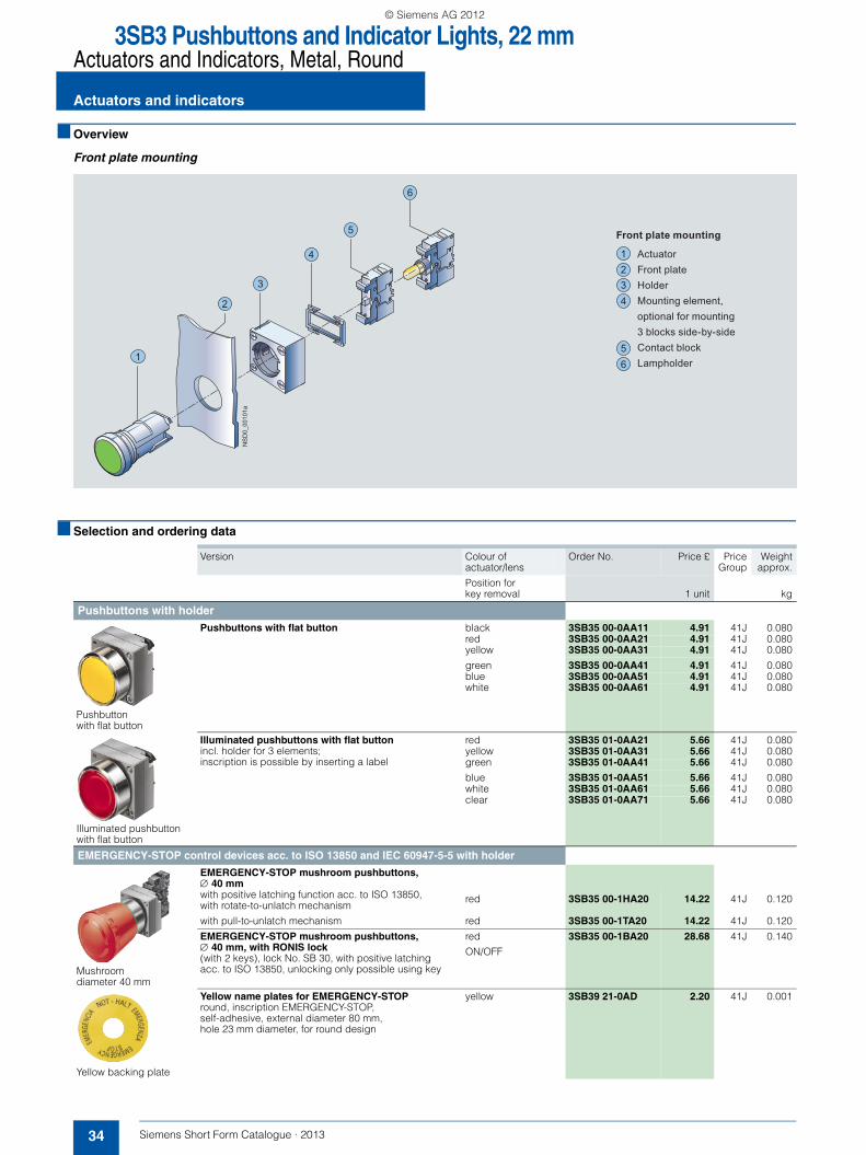
3SB3 Pushbuttons and Indicator Lights, 22 mmActuators and Indicators, Metal, Round
Actuators and indicators
34 Siemens Short Form Catalogue · 2013
■ Overview
Front plate mounting
■ Selection and ordering data
1
2
3
4
5
6
Front plate mounting
ActuatorFront plateHolderMounting element,optional for mounting3 blocks side-by-sideContact blockLampholder
1234
56
NS
D0_
0010
1a
Version Colour of actuator/lens
Order No. Price £ PriceGroup
Weightapprox.
Position for key removal 1 unit kg
Pushbuttons with holder
Pushbutton with flat button
Pushbuttons with flat button black 3SB35 00-0AA11 4.91 41J 0.080red 3SB35 00-0AA21 4.91 41J 0.080yellow 3SB35 00-0AA31 4.91 41J 0.080
green 3SB35 00-0AA41 4.91 41J 0.080blue 3SB35 00-0AA51 4.91 41J 0.080white 3SB35 00-0AA61 4.91 41J 0.080
Illuminated pushbutton with flat button
Illuminated pushbuttons with flat buttonincl. holder for 3 elements;inscription is possible by inserting a label
red 3SB35 01-0AA21 5.66 41J 0.080yellow 3SB35 01-0AA31 5.66 41J 0.080green 3SB35 01-0AA41 5.66 41J 0.080
blue 3SB35 01-0AA51 5.66 41J 0.080white 3SB35 01-0AA61 5.66 41J 0.080clear 3SB35 01-0AA71 5.66 41J 0.080
EMERGENCY-STOP control devices acc. to ISO 13850 and IEC 60947-5-5 with holder
Mushroom diameter 40 mm
EMERGENCY-STOP mushroom pushbuttons, ∅ 40 mmwith positive latching function acc. to ISO 13850, with rotate-to-unlatch mechanism
red 3SB35 00-1HA20 14.22 41J 0.120
with pull-to-unlatch mechanism red 3SB35 00-1TA20 14.22 41J 0.120
EMERGENCY-STOP mushroom pushbuttons,∅ 40 mm, with RONIS lock(with 2 keys), lock No. SB 30, with positive latching acc. to ISO 13850, unlocking only possible using key
red
ON/OFF
3SB35 00-1BA20 28.68 41J 0.140
Yellow backing plate
Yellow name plates for EMERGENCY-STOPround, inscription EMERGENCY-STOP, self-adhesive, external diameter 80 mm,hole 23 mm diameter, for round design
yellow 3SB39 21-0AD 2.20 41J 0.001
SFC_2012.book Seite 34 Montag, 10. Dezember 2012 8:19 08
© Siemens AG 2012
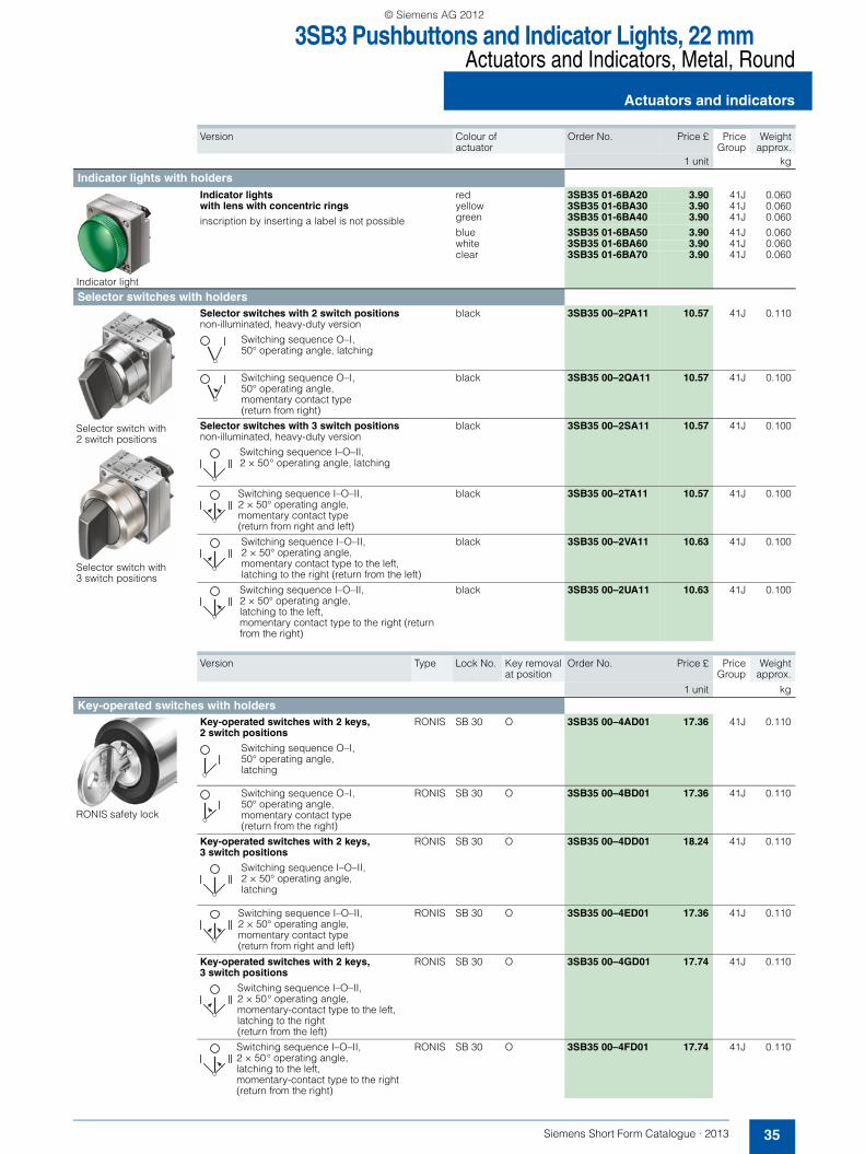
3SB3 Pushbuttons and Indicator Lights, 22 mmActuators and Indicators, Metal, Round
35Siemens Short Form Catalogue · 2013
Actuators and indicators
Version Colour of actuator
Order No. Price £ PriceGroup
Weightapprox.
1 unit kg
Indicator lights with holders
Indicator light
Indicator lights with lens with concentric rings
inscription by inserting a label is not possible
red 3SB35 01-6BA20 3.90 41J 0.060yellow 3SB35 01-6BA30 3.90 41J 0.060green 3SB35 01-6BA40 3.90 41J 0.060
blue 3SB35 01-6BA50 3.90 41J 0.060white 3SB35 01-6BA60 3.90 41J 0.060clear 3SB35 01-6BA70 3.90 41J 0.060
Selector switches with holders
Selector switch with 2 switch positions
Selector switch with 3 switch positions
Selector switches with 2 switch positionsnon-illuminated, heavy-duty version
Switching sequence O–I,50° operating angle, latching
black 3SB35 00–2PA11 10.57 41J 0.110
Switching sequence O–I,50° operating angle,momentary contact type (return from right)
black 3SB35 00–2QA11 10.57 41J 0.100
Selector switches with 3 switch positionsnon-illuminated, heavy-duty version
Switching sequence I–O–II,2 × 50° operating angle, latching
black 3SB35 00–2SA11 10.57 41J 0.100
Switching sequence I–O–II,2 × 50° operating angle,momentary contact type(return from right and left)
black 3SB35 00–2TA11 10.57 41J 0.100
Switching sequence I–O–II, 2 × 50° operating angle,momentary contact type to the left, latching to the right (return from the left)
black 3SB35 00–2VA11 10.63 41J 0.100
Switching sequence I–O–II, 2 × 50° operating angle,latching to the left, momentary contact type to the right (return from the right)
black 3SB35 00–2UA11 10.63 41J 0.100
Version Type Lock No. Key removalat position
Order No. Price £ PriceGroup
Weightapprox.
1 unit kg
Key-operated switches with holders
RONIS safety lock
Key-operated switches with 2 keys,2 switch positions
Switching sequence O–I,50° operating angle, latching
RONIS SB 30 O 3SB35 00–4AD01 17.36 41J 0.110
Switching sequence O–I,50° operating angle,momentary contact type(return from the right)
RONIS SB 30 O 3SB35 00–4BD01 17.36 41J 0.110
Key-operated switches with 2 keys,3 switch positions
Switching sequence I–O–II,2 × 50° operating angle, latching
RONIS SB 30 O 3SB35 00–4DD01 18.24 41J 0.110
Switching sequence I–O–II,2 × 50° operating angle,momentary contact type(return from right and left)
RONIS SB 30 O 3SB35 00–4ED01 17.36 41J 0.110
Key-operated switches with 2 keys, 3 switch positions
Switching sequence I–O–II,2 × 50° operating angle,momentary-contact type to the left,latching to the right (return from the left)
RONIS SB 30 O 3SB35 00–4GD01 17.74 41J 0.110
Switching sequence I–O–II,2 × 50° operating angle,latching to the left,momentary-contact type to the right (return from the right)
RONIS SB 30 O 3SB35 00–4FD01 17.74 41J 0.110
SFC_2012.book Seite 35 Montag, 10. Dezember 2012 8:19 08
© Siemens AG 2012

3SB3 Pushbuttons and Indicator Lights, 22 mmComponents for Actuators and Indicators
Holders, lamps and label holders
36 Siemens Short Form Catalogue · 2013
■ Selection and ordering data
1) Free labeling software can be downloaded from www.siemens.com/sirius-label-designer
Version Used for Lamp voltage Order No. Price £ PriceGroup
Weightapprox.
Packing
Design 1 unit kg Units
Holders for 3 contact blocks, for front panel mounting
Holder for pushbutton units
Holders for pushbuttons and switchesfor snapping on 3 blocks
Pushbuttons, push-pull buttons, mushroom push-buttons with front panel mounting
-- 3SB39 01-0AB 0.21 41J 0.001 20
Holder for knobs, locks and double pushbuttons
Holders for selector switches, key-operated switches and twin push-buttonswith pressure plate for actuating the central contact block of 3 contact blocks
Selector switches, key-operated switches with front plate mounting
-- 3SB39 01-0AC 0.28 41J 0.002 10
Lamps for bayonet connection base BA 9s
3SX1 344
Incandescent lamps 2Wmax. length 28 mmmax. bulb diameter 10 mm
-- 24 V AC/DC 3SX1 344 1.51 41J 0.003 10
3SB39 01-1QA
LED lamps, super brightmax. length 28 mmmax. bulb diameter 10 mmmax. operational current 15 mA
Illuminated push-button units and indicator lights
24 V AC/DC
red 3SB39 01-1CA 5.22 41J 0.002 10yellow 3SB39 01-1BA 5.22 41J 0.002green 3SB39 01-1DA 5.22 41J 0.002blue 3SB39 01-1PA 5.22 41J 0.002white 3SB39 01-1QA 5.22 41J 0.002
Label holders and inscription labels1)
3SB39 22-0AV
Label holders for round range, flatfor self-adhesive inscription label12.5 mm × 27 mm
-- -- 3SB39 22-0AV 0.40 41J 0.002 10
3SB39 02-1AA
Inscription labelsself-adhesive, blank 12.5 mm × 27 mm
-- -- 3SB39 02-1AA 0.32 41J 0.001 10
SFC_2012.book Seite 36 Montag, 10. Dezember 2012 8:19 08
© Siemens AG 2012

3SB3 Pushbuttons and Indicator Lights, 22 mmComponents for Actuators and Indicators
37Siemens Short Form Catalogue · 2013
Contact blocks and lampholders
■ Selection and ordering data
1) Positive opening according to IEC 60947-5-1, Appendix K.
Version Symbols Colour/Operating travel Screw terminals PriceGroup
Weightapprox.
contact closed Order No. Price £1 unit kg contact open
Contact blocks for front plate mounting
3SB34 00-0B
Contact blocks with one contact50 mm mounting depth
1 NO 3SB34 00–0B 3.08 41J 0.011
1 NC q1)
3SB34 00–0C 3.08 41J 0.011
3SB34 00-0A
Contact blocks with two contacts 65 mm mounting depth
1 NO + 1 NC q1) 3SB34 00–0A 4.72 41J 0.018
1 NO leading + 1 NC delayed
3SB34 00-0H 6.48 41J 0.018
2 NO 3SB34 00–0D 6.48 41J 0.018
2 NC q1) 3SB34 00–0E 6.48 41J 0.018
3SB34 00-1A
BA 9s lampholders50 mm mounting depth
without lamp 3SB34 00–1A 3.08 41J 0.010
Lampholders with integrated LED 50 mm mounting depth
3SB34 00-1PA
24 V AC/DC yellow 3SB34 00–1PA 4.40 41J 0.011red 3SB34 00–1PB 4.40 41J 0.011green 3SB34 00–1PC 4.40 41J 0.011blue 3SB34 00–1PD 4.40 41J 0.011white 3SB34 00–1PE 4.40 41J 0.011
110 V AC yellow 3SB34 00–1QA 7.80 41J 0.012red 3SB34 00–1QB 7.80 41J 0.012green 3SB34 00–1QC 7.80 41J 0.012blue 3SB34 00–1QD 7.80 41J 0.012white 3SB34 00–1QE 7.80 41J 0.012
230 V AC yellow 3SB34 00–1RA 7.80 41J 0.012red 3SB34 00–1RB 7.80 41J 0.012green 3SB34 00–1RC 7.80 41J 0.012blue 3SB34 00–1RD 7.80 41J 0.012white 3SB34 00–1RE 7.80 41J 0.012
NS
D0_
0000
6
.4
.3
2,3
3-4421
mm0 3
NSD0_00015
.2
.1N
SD
0_00
007
1-2
1,6
421mm0 3
NSD0_00017
NS
D0_
0003
3
.2.4
.1.3
2,31,6
3-41-2
421mm0 3
NSD0_00038
NS
D0_
0003
4
.6.8
.7 .5
2,21,3
7-85-6
421mm0 3
NSD0_00037b
NS
D0_
0003
5
.4.4
.3 .3
3-4
2,3
3-4
421mm0 3
NSD0_00039
NS
D0
_0
00
36
.2.2
.1.11-21-2
1,6
421mm0 3
NSD0_00040
(L-)(L+)X2X1
NSD0_00003
+k
k
NSD0_01292b
+k
k
NSD0_01296b
X1
X2
+k
k
NSD0_01296b
X1
X2
SFC_2012.book Seite 37 Montag, 10. Dezember 2012 8:19 08
© Siemens AG 2012

3SB3 Pushbuttons and Indicator Lights, 22 mmComponents for Actuators and Indicators
Contact blocks and lampholders
38 Siemens Short Form Catalogue · 2013
1) Positive opening according to IEC 60947-5-1, Appendix K.
Version Rated voltage of lamp/Symbols
Colour/Operating travel Spring-loaded terminals
PriceGroup
Weightapprox.
kg contact closed Order No. Price £
1 unit contact open
Contact blocks for front plate mounting
3SB34 03-0B
Contact blocks with one contact 50 mm mounting depth, 30 mm × 30 mm grid
1 NO 3SB34 03-0B 3.46 41J 0.008
1 NC q1) 3SB34 03-0C 3.46 41J 0.008
3SB34 03-0A
Contact blocks with two contacts65 mm mounting depth
1 NO + 1 NC q1) 3SB34 03-0A 5.16 41J 0.018
1 NO leading + 1 NC delayed
3SB34 03-0H 6.98 41J 0.018
2 NO 3SB34 03-0D 6.98 41J 0.017
2 NC q1) 3SB34 03-0E 6.98 41J 0.018
3SB34 03-1A
BA 9s lampholders50 mm mounting depth, 30 mm × 30 mm grid
without lamp according to lamp 3SB34 03-1A 3.46 41J 0.008
3SB34 03-1PA
Lampholders with integrated LED50 mm mounting depth, 30 mm × 30 mm grid
24 V AC/DC yellow 3SB34 03-1PA 4.84 41J 0.009red 3SB34 03-1PB 4.84 41J 0.010green 3SB34 03-1PC 4.84 41J 0.009blue 3SB34 03-1PD 4.84 41J 0.009white 3SB34 03-1PE 4.84 41J 0.009
110 V AC yellow 3SB34 03-1QA 8.81 41J 0.010red 3SB34 03-1QB 8.81 41J 0.010green 3SB34 03-1QC 8.81 41J 0.010blue 3SB34 03-1QD 8.81 41J 0.010white 3SB34 03-1QE 8.81 41J 0.010
230 V AC yellow 3SB34 03-1RA 8.81 41J 0.010red 3SB34 03-1RB 8.81 41J 0.010green 3SB34 03-1RC 8.81 41J 0.010blue 3SB34 03-1RD 8.81 41J 0.010white 3SB34 03-1RE 8.81 41J 0.010
NS
D0_
0000
6
.4
.3
2,3
3-4421
mm0 3
NSD0_00015
.2
.1
NS
D0_
0000
7
1-2
1,6
421mm0 3
NSD0_00017
NS
D0_
0003
3
.2.4
.1.3
2,31,6
3-41-2
421mm0 3
NSD0_00038
NS
D0_
0003
4
.6.8
.7 .5
2,21,3
7-85-6
421mm0 3
NSD0_00037b
NS
D0_
0003
5
.4.4
.3 .3
3-4
2,3
3-4
421mm0 3
NSD0_00039
NS
D0_
0003
6
.2.2
.1.11-21-2
1,6
421mm0 3
NSD0_00040
(L-)(L+)X2X1
NSD0_00003
+k
k
NSD0_01292b
X1
X2 +k
k
NSD0_01292b
X1
X2
+k
k
NSD0_01296b
X1
X2
+k
k
NSD0_01296b
X1
X2
SFC_2012.book Seite 38 Montag, 10. Dezember 2012 8:19 08
© Siemens AG 2012
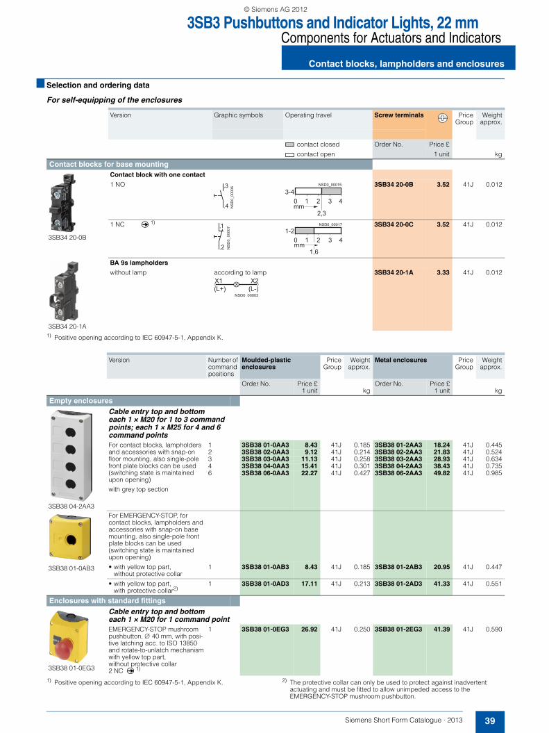
3SB3 Pushbuttons and Indicator Lights, 22 mmComponents for Actuators and Indicators
39Siemens Short Form Catalogue · 2013
Contact blocks, lampholders and enclosures
■ Selection and ordering data
For self-equipping of the enclosures
1) Positive opening according to IEC 60947-5-1, Appendix K.
1) Positive opening according to IEC 60947-5-1, Appendix K. 2) The protective collar can only be used to protect against inadvertent actuating and must be fitted to allow unimpeded access to the EMERGENCY-STOP mushroom pushbutton.
Version Graphic symbols Operating travel Screw terminals PriceGroup
Weightapprox.
contact closed Order No. Price £
contact open 1 unit kg
Contact blocks for base mounting
3SB34 20-0B
Contact block with one contact
1 NO
3SB34 20-0B 3.52 41J 0.012
1 NC q1)
3SB34 20-0C 3.52 41J 0.012
3SB34 20-1A
BA 9s lampholders
without lamp according to lamp
3SB34 20-1A 3.33 41J 0.012
NS
D0_
0000
6
.4
.3
2,3
3-4421
mm0 3
NSD0_00015
.2
.1N
SD
0_00
007
1-2
1,6
421mm0 3
NSD0_00017
(L-)(L+)X2X1
NSD0 00003
Version Number of command positions
Moulded-plastic enclosures
PriceGroup
Weightapprox.
Metal enclosures PriceGroup
Weightapprox.
Order No. Price £1 unit kg
Order No. Price £1 unit kg
Empty enclosures
3SB38 04-2AA3
Cable entry top and bottom each 1 × M20 for 1 to 3 command points; each 1 × M25 for 4 and 6 command pointsFor contact blocks, lampholders and accessories with snap-on floor mounting, also single-pole front plate blocks can be used (switching state is maintained upon opening)
with grey top section
1 3SB38 01-0AA3 8.43 41J 0.185 3SB38 01-2AA3 18.24 41J 0.4452 3SB38 02-0AA3 9.12 41J 0.214 3SB38 02-2AA3 21.83 41J 0.5243 3SB38 03-0AA3 11.13 41J 0.258 3SB38 03-2AA3 28.93 41J 0.6344 3SB38 04-0AA3 15.41 41J 0.301 3SB38 04-2AA3 38.43 41J 0.7356 3SB38 06-0AA3 22.27 41J 0.427 3SB38 06-2AA3 49.82 41J 0.985
3SB38 01-0AB3
For EMERGENCY-STOP, for contact blocks, lampholders and accessories with snap-on base mounting, also single-pole front plate blocks can be used (switching state is maintained upon opening)
• with yellow top part,without protective collar
1 3SB38 01-0AB3 8.43 41J 0.185 3SB38 01-2AB3 20.95 41J 0.447
• with yellow top part, with protective collar2)
1 3SB38 01-0AD3 17.11 41J 0.213 3SB38 01-2AD3 41.33 41J 0.551
Enclosures with standard fittings
3SB38 01-0EG3
Cable entry top and bottom each 1 × M20 for 1 command pointEMERGENCY-STOP mushroom pushbutton, ∅ 40 mm, with posi-tive latching acc. to ISO 13850 and rotate-to-unlatch mechanismwith yellow top part, without protective collar2 NC q
1)
1 3SB38 01-0EG3 26.92 41J 0.250 3SB38 01-2EG3 41.39 41J 0.590
SFC_2012.book Seite 39 Montag, 10. Dezember 2012 8:19 08
© Siemens AG 2012

6EP1 Regulated Power Supplies
SITOP compact, 1-phase
40 Siemens Short Form Catalogue · 2013
■ Overview
The slim power supply unit for control boxes
Thanks to the extremely space-saving slim design, the new power supply series for the lower performance range is espe-cially suited to distributed applications in control boxes or in small control cabinets. The switched-mode power supplies are characterized by their low power losses throughout the load
range. The losses are extremely low even during idling which predestines them for supplying machines and plants which are frequently in stand-by mode. The SITOP PSU100C power sup-plies have a wide-range input for AC and DC networks; plug-in terminals facilitate the electrical connection.
■ Selection and ordering data
For other versions, see catalogue KT 10.1.
Version Input Output Dimension(B x H x T)
Order No. Price £ PriceGroup
Weightapprox.
Rated voltageUe rated
Rated voltageUa rated
Rated currentIa rated
mm 1 unit kg
Power Supplies 24 V
6EP1 331-5BA00
0,6 A 100 ... 230 V AC(85 ... 264 V AC/110 ... 300 V DC)
24 V DC±3 %
0,6 A 22,5 x 80 x 100 6EP1 331-5BA00 35.–– 584 0.120
6EP1 331-5BA10
1,3 A 100 ... 230 V AC(85 ... 264 V AC/110 ... 300 V DC)
24 V DC±3 %
1,3 A 30 x 80 x 100 6EP1 331-5BA10 45.–– 584 0.170
6EP1 332-5BA00
2,5 A 100 ... 230 V AC(85 ... 264 V AC/110 ... 300 V DC)
24 V DC±3 %
2,5 A 45 x 80 x 100 6EP1 332-5BA00 59.–– 584 0.220
6EP1 332-5BA10
4 A 100 ... 230 V AC(85 ... 264 V AC/110 ... 300 V DC)
24 V DC±3 %
4 A 52,5 x 80 x 100 6EP1 332-5BA10 85.–– 584 0.310
Power Supplies 12 V
6EP1 321-5BA00
2 A 100 ... 230 V AC(85 ... 264 V AC/110 ... 300 V DC)
12 V DC±3 %
2 A 30 x 80 x 100 6EP1 321-5BA00 59.–– 584 0.170
6EP1 322-5BA10
6,5 A 100 ... 230 V AC(85 ... 264 V AC/110 ... 300 V DC)
12 V DC±3 %
6,5 A 52,5 x 80 x 100 6EP1 322-5BA10 89.–– 584 0.310
SFC_2012.book Seite 40 Montag, 10. Dezember 2012 8:19 08
© Siemens AG 2012

6EP1 Regulated Power Supplies
41Siemens Short Form Catalogue · 2013
LOGO!Power, 1-phaseSITOP modular, 1-phase, 2-phase and 3-phase
■ Overview
LOGO!Power
With LOGO!Power power supplies it is possible not only for 24 V loads to benefit from the advantages of a stabilized power supply - loads with a 5 V, 12 V and 15 V supply voltage can now do likewise. For each of these three voltages there are two levels ofcurrent available, and for 24 V there is even a 4 A version in a width of only 90 mm.
The primary switched power supplies can be used for a widerange of different applications: In automation systems for industry and buildings, solar technology, measurement and closedloop control, sensors, for supplying electronic circuits in TTL technology, etc.
SITOP modular
The technology power supply for demanding solutions
SITOP modular fulfills the highest functionality requirements, e.g. for use in complex plants and machines. The wide-range input allows a connection to almost any electrical power system world-wide and ensures a high degree of safety even if there are large voltage fluctuations. The power boost provides up to three times the rated current for brief periods. In the event of an overload, you have two options: Constant current with automatic restart or latching shutdown.
The innovated SITOP PSU100M 20 A power supply units with 1-phase connection and SITOP PSU300M 20 and 40 A 3-phase. Due to their slim design, they are among the most compact units in their performance class. The innovations include the inte-grated signaling contact for "24 V o. k.", the extended input range, the high efficiency of 93%, and 1.5 times the rated current for up to 5 seconds.
■ Selection and ordering data
For other versions, see catalogue KT 10.1.
Version Input Output Dimension(B x H x T)
Order No. Price £ PriceGroup
Weightapprox.Rated voltage
Ue rated
Rated voltageUa rated
Rated currentIa rated
mm 1 unit kg
Power Supplies 24 VLOGO!Power
6EP1 331-1SH03
1.3 A 100 … 240 V AC(93 … 264 V AC)
24 V DC±3 %
1.3 A 54 x 90 x 55 6EP1 331-1SH03 47.–– 583 0.170
2.5 A 100 … 240 V AC(93 … 264 V AC)
24 V DC±3 %
2.5 A 72 x 90 x 55 6EP1 332-1SH43 76.–– 583 0.250
4 A 100 … 240 V AC(93 … 264 V AC)
24 V DC±3 %
4 A 90 x 90 x 55 6EP1 332-1SH52 93.–– 583 0.340
SITOP modular
6EP1 333-3BA00
5 A 120/230 ... 500 V AC(85 ... 264 V/176 ... 550 V AC)
24 V DC ±3 %
5 A 70 x 125 x 125 6EP1 333-3BA00 130.–– 581 1.200
10 A 120/230 ... 500 V AC(85 ... 264 V/176 ... 550 V AC)
24 V DC ±3 %
10 A 90 x 125 x 125 6EP1 334-3BA00 170.–– 581 1.400
6EP1 336-3BA10
20 A 120/230 ... 500 V AC(85 ... 275 V AC or88 ... 350 V DC)
24 V DC ±3 %
20 A 90 x 125 x 125 6EP1 336-3BA10 251.–– 581 1.200
20 A 3 AC 400 ... 500 V (3 AC 320 ... 575 V)
24 V DC ±3 %
20 A 70 x 125 x 125 6EP1 436-3BA10 209.–– 581 1.200
6EP1 337-3BA00
40 A 120/230 V AC(85 ... 132 V/176 ... 264 V AC)
24 V DC ±3 %
40 A 240 x 125 x 125 6EP1 337-3BA00 349.–– 581 2.900
6EP1 437-3BA10
40 A 3 AC 400 ... 500 V (3 AC 320 ... 575 V)
24 V DC ±3 %
40 A 150 x 125 x 150 6EP1 437-3BA10 326.–– 581 3.400
Power Supplies 48 VSITOP modular
6EP1 456-3BA00
10 A 3 AC 400 ... 500 V (3 AC 320 ... 575 V)
48 V DC ±3 %
10 A 70 x 125 x 125 6EP1 456-3BA00 220.–– 581 1.200
SFC_2012.book Seite 41 Montag, 10. Dezember 2012 8:19 08
© Siemens AG 2012

3LD Main Control and EMERGENCY-STOP Switches up to 125 A
Floor mounting, moulded-plastic enclosures
42 Siemens Short Form Catalogue · 2013
■ Overview
The 3LD switches are used for switching main and auxiliary circuits, but also for switching induction motors and other loads during maintenance and repair work.
They are manually operated switch disconnectors according to IEC 60947-3/VDE 0660 Part 107 (IEC 60947-3) and comply with the conditions for switch disconnectors.
The 3LD can be used as• ON-OFF switch• EMERGENCY-STOP switch• Main control switch according to IEC 60204-1
In IEC 60204-1 (VDE 0113 Part 1), main switches are called "mains isolating devices", while EMERGENCY-STOP switches are termed "devices for emergency shutdown". Maintenance personnel can protect themselves against unauthorized startup with padlocks (up to three can be fitted).
3LD main control and EMERGENCY-STOP switches are approved according to UL 508.
■ Selection and ordering data
1) 4th contact element as N conductor to be ordered separately.
Floor mounting Moulded-plastic enclosures
Main control and EMERGENCY-STOP switches with door-coupling rotary operating mechanism• Red/yellow (EMERGENCY-STOP)• With 300 mm switch shaft• Lockable in 0 position with max. 3 padlocks• IP65 degree of protection at the front• Door-coupling rotary operating mechanism
with integrated tolerance compensation• Mounting using screws or snap-on mounting on 35
mm standard mounting rail• Including terminal cover for the infeed side• Front plate
- 3LD2 0, 3LD2 1, 3LD2 2: 67 mm × 67 mm- 3LD2 5 to 3LD2 8: 90 mm × 90 mm
• Installation dimension3LD2 0, 3LD2 1, 3LD2 2: 380 mm- 3LD2 5 to 3LD2 8: 390 mm.
Four-hole mounting
3LD2 213-0TK53
Main control and EMERGENCY-STOP switches• Red/yellow (EMERGENCY-STOP)• With N- and/or PE-ground terminal• Lockable in 0 position with upto max. 3 padlocks• IP 65 degree of protection at the front• Rotary operating mechanisms with center-hole
mounting• For floor-mounting auxiliary switches• Metric srewed glands.
3LD2 164-0TB53
Number and version of contacts
Rated data at 50 ... 60 Hz380 ... 440 V
Order No. Price £ PriceGroup
Weightapprox.
Order No. Price £ PriceGroup
Weightapprox.
Main elements
Aux. elements
P/AC-23A
Iu
kW A 1 unit kg 1 unit kg
3 -- 7.5 16 3LD2 013–0TK53 24.70 12R 0.412 3LD2 064-0TB53 21.83 12R 0.4639.5 25 3LD2 113–0TK53 27.33 12R 0.407 3LD2 164–0TB53 23.74 12R 0.46311.5 32 3LD2 213–0TK53 30.08 12R 0.405 3LD2 264–0TB53 28.17 12R 0.465
22 63 3LD2 514–0TK53 36.06 12R 0.655 3LD2 565–0TB53 46.82 12R 0.90637 100 3LD2 714–0TK53 59.38 12R 0.765 3LD2 766–0TB53 106.44 12R 1.89045 125 3LD2 814–0TK53 73.55 12R 0.766 3LD2 866–0TB53 193.15 12R 1.890
3 + N -- 7.5 16 3LD2 013–1TL53 28.11 12R 0.412 3LD2 064-1TC53 31.87 12R 0.4539.5 25 3LD2 113–1TL53 31.28 12R 0.450 3LD2 164–1TC53 35.28 12R 0.48711.5 32 3LD2 213–1TL53 34.27 12R 0.446 3LD2 264–1TC53 39.77 12R 0.50022 63 3LD2 514–1TL53 43.53 12R 0.720 3LD2 565–1TC53 54.24 12R 0.960
37 100 3LD2 714–0TK53 59.38 12R 0.765 3LD2 766–0TB53 106.44 12R 1.860+1) +1)
3LD9 280-0C 12.44 12R 0.102 3LD9 280-0C 12.44 12R 0.102
45 125 3LD2 814–0TK53 73.55 12R 0.766 3LD2 866–0TB53 193.15 12R 1.860+1) +1)
3LD9 280-0C 12.44 12R 0.102 3LD9 280-0C 12.44 12R 0.102
SFC_2012.book Seite 42 Montag, 10. Dezember 2012 8:19 08
© Siemens AG 2012

5SY Miniature Circuit Breakers
43Siemens Short Form Catalogue · 2013
High-capacity range
■ Selection and ordering data
• Un: 230/400 AC V, 50-60 Hz, applicable in networks up to 250/440 V AC, 60 V DC per pole
• Standards IEC 60898, (VDE 0641 Part 11), IEC 60898• Supplementary components can be retrofitted• 70 mm mounting depth
Characteristics C
General line protection, especially advantageous with higher inrush currents (lamps, motors, etc.).
Characteristics D
Tripping range adapted to operating equipment involving significant pulse generation (transformers, solenoid valves).
Version In MW Characteristic C PriceGroup
Characteristic D PriceGroup
Weightapprox.
Order No. Price £ Order No. Price £
A 1 unit 1 unit kg
Miniature circiut breakers 6000 A
5SY6 1
1P, 230/400 V AC
0.5 1 5SY6 105-7 11.30 001 5SY4 105-8 13.40 002 0.1651 5SY6 101-7 11.30 001 5SY4 101-8 13.40 002 0.165
1.6 5SY6 115-7 11.30 001 5SY4 115-8 13.40 002 0.1472 5SY6 102-7 11.30 001 5SY4 102-8 13.40 002 0.1653 5SY6 103-7 11.30 001 5SY4 103-8 13.40 002 0.165
4 5SY6 104-7 10.60 001 5SY4 104-8 13.20 002 0.1656 5SY6 106-7 10.40 001 5SY4 106-8 12.70 002 0.1658 5SY6 108-7 9.50 001 5SY4 108-8 11.80 002 0.165
10 5SY6 110-7 9.50 001 5SY4 110-8 11.80 002 0.16513 5SY6 113-7 9.50 001 5SY4 113-8 11.80 002 0.16516 5SY6 116-7 9.50 001 5SY4 116-8 11.80 002 0.165
20 5SY6 120-7 9.50 001 5SY4 120-8 11.80 002 0.16525 5SY6 125-7 9.50 001 5SY4 125-8 11.80 002 0.16532 5SY6 132-7 9.50 001 5SY4 132-8 11.80 002 0.165
40 5SY6 140-7 10.40 001 5SY4 140-8 12.70 002 0.16550 5SY6 150-7 10.60 001 5SY4 150-8 13.20 002 0.16563 5SY6 163-7 11.30 001 5SY4 163-8 13.40 002 0.165
5SY6 2
2P,400 V AC
0.5 2 5SY6 205-7 31.50 001 5SY4 205-8 38.50 002 0.3301 5SY6 201-7 31.50 001 5SY4 201-8 38.50 002 0.330
1.6 5SY6 215-7 31.50 001 5SY4 215-8 38.50 002 0.3302 5SY6 202-7 31.50 001 5SY4 202-8 38.50 002 0.3303 5SY6 203-7 31.50 001 5SY4 203-8 38.50 002 0.330
4 5SY6 204-7 31.25 001 5SY4 204-8 38.25 002 0.3306 5SY6 206-7 29.75 001 5SY4 206-8 36.25 002 0.3308 5SY6 208-7 27.50 001 5SY4 208-8 33.25 002 0.330
10 5SY6 210-7 27.50 001 5SY4 210-8 33.25 002 0.33013 5SY6 213-7 27.50 001 5SY4 213-8 33.25 002 0.33016 5SY6 216-7 27.50 001 5SY4 216-8 33.25 002 0.330
20 5SY6 220-7 27.50 001 5SY4 220-8 33.25 002 0.33025 5SY6 225-7 27.50 001 5SY4 225-8 33.25 002 0.33032 5SY6 232-7 27.50 001 5SY4 232-8 33.25 002 0.330
40 5SY6 240-7 29.75 001 5SY4 240-8 36.25 002 0.33050 5SY6 250-7 31.25 001 5SY4 250-8 38.25 002 0.33063 5SY6 263-7 31.50 001 5SY4 263-8 38.50 002 0.330
5SY6 3
3P,400 V AC
0.5 3 5SY6 305-7 48.–– 001 5SY4 305-8 56.–– 002 0.4951 5SY6 301-7 48.–– 001 5SY4 301-8 56.–– 002 0.495
1.6 5SY6 315-7 48.–– 001 5SY4 315-8 56.–– 002 0.4952 5SY6 302-7 48.–– 001 5SY4 302-8 56.–– 002 0.4953 5SY6 303-7 48.–– 001 5SY4 303-8 56.–– 002 0.495
4 5SY6 304-7 46.25 001 5SY4 304-8 54.–– 002 0.4956 5SY6 306-7 43.75 001 5SY4 306-8 53.–– 002 0.4958 5SY6 308-7 41.–– 001 5SY4 308-8 50.–– 002 0.495
10 5SY6 310-7 41.–– 001 5SY4 310-8 50.–– 002 0.49513 5SY6 313-7 41.–– 001 5SY4 313-8 50.–– 002 0.49516 5SY6 316-7 41.–– 001 5SY4 316-8 50.–– 002 0.495
20 5SY6 320-7 41.–– 001 5SY4 320-8 50.–– 002 0.49525 5SY6 325-7 41.–– 001 5SY4 325-8 50.–– 002 0.49532 5SY6 332-7 41.–– 001 5SY4 332-8 50.–– 002 0.495
40 5SY6 340-7 43.75 001 5SY4 340-8 53.–– 002 0.49550 5SY6 350-7 46.25 001 5SY4 350-8 54.–– 002 0.49563 5SY6 363-7 48.–– 001 5SY4 363-8 56.–– 002 0.495
6 0003
1
2
1
2
3
4
2
1
4
3
6
5
SFC_2012.book Seite 43 Montag, 10. Dezember 2012 8:19 08
© Siemens AG 2012

5SY Miniature Circuit Breakers
Auxiliary switches
44 Siemens Short Form Catalogue · 2013
■ Overview
• Can be individually retrofitted• Mounting with factory-installed clips• Short-circuit protection via miniature circuit-breakers or
characteristic C and In = 6 A or gG 6 A fuses• Broad range of applications thanks to the additional version
for controlling programmable controllers (PLC) acc. to IEC 61131-2
• Connectable to instabus EIB and AS-Interface bus via binary inputs
• Max. contact load:
• Indication of the miniature circuit-breaker’s switching state:- AS: ON/OFF
■ Selection and ordering data
■ Overview
Busbar system• Acc. to DIN 57606 and DIN 57659• Load for one-side/central infeed:
65 A/120 A for 16 mm2
• Pin-type connections• Single and multi-phase
• Cu 16 mm2 fully insulated• 18 mm lug spacing• No additional connection terminal required for stranded
connections up to 35 mm2
• Excellent accessibility of the feeder cables
■ Selection and ordering data
NO contacts:2 A, 400 V AC, AC-146 A, 230 V AC, AC-141 A, 220 V DC, DC-131 A, 110 V DC, DC-133 A, 60 V DC, DC-136 A, 24 V DC, DC-13
NC contacts:2 A, 400 V AC, AC-136 A, 230 V AC, AC-131 A, 220 V DC, DC-131 A, 110 V DC, DC-133 A, 60 V DC, DC-136 A, 24 V DC, DC-13
Version MW Order No. Price £ PriceGroup
Weightapprox.
1 unit kg
Auxiliary switches
5ST3 010
Auxiliary switches (AS) for small output
1 NO + 1 NC 0.5 5ST3 010 19.–– 11E 0.050
2 NO 0.5 5ST3 011 19.–– 11E 0.050
2214
1321
2414
1323
Accessories for 5SY miniature circuit breakers
Version Length Order No. Price £ PriceGroup
Weightapprox.
mm 1 unit kg
5ST3 7 busbar systems, 16 mm2
5ST3 7
Can be cut, without end caps
1-phase, angled, for MCB 1P 1 016 5ST3 701 15.50 12E 0.189
2-phase, for MCB 2P 5ST3 705 43.25 12E 0.289
3-phase, for MCB 3P 5ST3 710 65.–– 12E 0.430
End caps for 5ST3 7, can be cut
5ST3 7
Required to isolate the ends of cut-to-length busbars
for 1-phase busbars 5ST3 748 0.67 12E 0.001
for 2- and 3-phase busbars 5ST3 750 1.06 12E 0.001
SFC_2012.book Seite 44 Montag, 10. Dezember 2012 8:19 08
© Siemens AG 2012

Industrial Controls
45Siemens Short Form Catalogue · 2013
Motor power,motor nominal current
■ Technical Information
Motor power Motor nominal current at:220 ... 230 V 240 V 380 ... 400 V 415 V 440 V 500 V 600 V 560 ... 690 V
kW PS = hp A A A A A A A A0.06 1/12 0.38 0.35 0.22 0.2 0.19 0.16 0.12 --0.09 1/8 0.55 0.5 0.33 0.3 0.28 0.24 0.21 -- 0.12 1/6 0.76 0.68 0.42 0.4 0.37 0.33 0.27 -- 0.18 1/4 1.1 1 0.64 0.6 0.55 0.46 0.4 -- 0.25 1/3 1.4 1.38 0.88 0.85 0.76 0.59 0.56 --
0.37 1/2 2.1 1.93 1.22 1.15 1.06 0.85 0.77 0.70.55 3/4 2.7 2.3 1.5 1.4 1.25 1.2 1.02 0.90.75 1 3.3 3.1 2 2 1.67 1.48 1.22 1.11.1 1.5 4.9 4.1 2.6 2.5 2.26 2.1 1.66 1.51.5 2 6.2 5.6 3.5 3.5 3.03 2.6 2.22 2
2.2 3 8.7 7.9 5 5 4.31 3.8 3.16 2.92.5 3.4 9.8 8.9 5.7 5.5 4.9 4.3 3.59 3.33 4 11.6 10.6 6.6 6.5 5.8 5.1 4.25 3.53.7 5 14.2 13 8.2 7.5 7.1 6.2 5.2 4.44 5.5 15.3 14 8.5 8.4 7.6 6.5 5.6 4.9
5 6.8 18.9 17.2 10.5 10 9.4 8.1 6.9 65.5 7.5 20.6 18.9 11.5 11 10.3 8.9 7.5 6.76.5 8.8 23.7 21.8 13.8 12.5 12 10.4 8.7 8.17.5 10 27.4 24.8 15.5 14 13.5 11.9 9.9 98 11 28.8 26.4 16.7 15.4 14.4 12.7 10.6 9.7
9 12.5 32 29.3 18.3 17 15.8 13.9 11.6 10.611 15 39.2 35.3 22 21 19.3 16.7 14.1 1312.5 17 43.8 40.2 25 23 21.9 19 16.1 1515 20 52.6 48.2 30 28 26.3 22.5 19.3 17.518.5 25 64.9 58.7 37 35 32 28.5 23.5 21
20 27 69.3 63.4 40 37 34.6 30.6 25.4 2322 30 75.2 68 44 40 37.1 33 27.2 2525 34 84.4 77.2 50 47 42.1 38 30.9 2830 40 101 92.7 60 55 50.1 44 37.1 3337 50 124 114 72 66 61.9 54 45.4 42
40 54 134 123 79 72 67 60 49.1 4445 60 150 136 85 80 73.9 64.5 54.2 4951 70 168 154 97 90 83.8 73.7 61.4 5655 75 181 166 105 96 90.3 79 66.2 6059 80 194 178 112 105 96.9 85.3 71.1 66
75 100 245 226 140 135 123 106 90.3 8280 110 260 241 147 138 131 112 96.3 8690 125 292 268 170 165 146 128 107 98100 136 325 297 188 182 162 143 119 107110 150 358 327 205 200 178 156 131 118
129 175 420 384 242 230 209 184 153 135132 180 425 393 245 242 214 186 157 140140 190 449 416 260 250 227 200 167 145147 200 472 432 273 260 236 207 173 152160 220 502 471 295 280 256 220 188 170
180 245 578 530 333 320 289 254 212 190184 250 590 541 340 325 295 259 217 200200 270 626 589 370 340 321 278 235 215220 300 700 647 408 385 353 310 260 235250 340 803 736 460 425 401 353 295 268
257 350 826 756 475 450 412 363 302 280295 400 948 868 546 500 473 416 348 320315 430 990 927 580 535 505 445 370 337355 480 1 080 1 010 636 580 549 483 405 366400 545 1 250 1 130 710 650 611 538 450 410
450 610 1 410 1 270 800 740 688 608 508 460475 645 1 490 1 340 850 780 730 645 540 485500 680 1 570 1 420 890 830 770 680 565 510
560 760 1 750 1 580 1 000 920 860 760 630 570600 810 -- -- 1 080 990 920 810 680 610670 910 -- -- 1 200 1 100 1 030 910 760 680
SFC_2012.book Seite 45 Montag, 10. Dezember 2012 8:19 08
© Siemens AG 2012
Industrial Controls
Conditions of sale and deliveryExport regulations
46 Siemens Short Form Catalogue · 2013
■ Conditions of Sale "A"1. GENERAL - The acceptance of our tender includes the accep-
tance of the following terms and conditions:-2. VALIDITY - Unless previously withdrawn, our tender is open for
acceptance within the period stated therein or, when no period is so stated, within thirty days only after its date.
3. ACCEPTANCE - The acceptance of our tender must be accom-panied by sufficient information to enable us to proceed with the order forthwith, otherwise we shall be at liberty to amend the ten-der prices to cover any increase in cost which has taken place after acceptance. Any samples submitted to you and not retur-ned to our works within one month from date of receipt shall be paid for by you.
4. PACKING - Unless otherwise specified in our tender, all packing cases, skids, drums and other packing materials must be retur-ned to our works at your expense and in good condition within one month from date of receipt. If not so returned they will be charged for.
5. LIMITS OF CONTRACT - Our tender includes only such goods, accessories and work as are specified therein.
6. DRAWINGS, ETC. - All specifications, drawings and particulars of weights and dimensions submitted with our tender are appro-ximate only, and the descriptions and illustrations contained in our catalogues, price lists and other advertisement matter are in-tended merely to present a general idea of the goods described therein, and none of these shall form part of the contract. After acceptance of our tender a set of certified outline drawings will be supplied free of charge on request.
7. INSPECTION AND TESTS - Our products are carefully inspected and, where practicable, submitted to our standard tests at our works before despatch. If tests other than those specified in our tender or tests in the presence of you or your representative are required, these will be charged for. In the event of any delay on your part in attending such tests or in carrying out any inspection required by you after seven days' notice that we are ready, the tests will proceed in your absence and shall be deemed to have been made in your presence.
8. PERFORMANCE - We will accept no liability for failure to attain any performance figures quoted by us unless we have specifi-cally guaranteed them, subject to any tolerances specified or agreed to by us, in an agreed sum as liquidated damages.If the performance figures obtained on any test provided for in the contract are outside the acceptance limits specified therein, you will be entitled to reject the goods.Before you become entitled to claim liquidated damages or to reject the goods we are to be given reasonable time and oppor-tunity to rectify their performance. If you become entitled to reject goods, we will repay to you any sum paid by you to us on account of the contract price thereof and any sum that may have accrued due to you in respect of delay in despatch under Clause 9 up to the date of such rejection.You assume responsibility that goods stipulated by you are suf-ficient and suitable for your purpose save in so far as your stipu-lations are in accordance with our advice.
9. LIABILITY FOR DELAY - Any times quoted for despatch or deli-very are to date from receipt by us of a written order to proceed and of all necessary information and drawings to enable us to put the work in hand. The time for despatch or delivery shall be extended by a reasonable period if delay in despatch or delivery is caused by instructions or lack of instructions from you or by industrial dispute or by any cause beyond our reasonable con-trol. If a fixed time be quoted for despatch or delivery, and we fail to despatch or deliver within that time or within any extension the-reof provided by this clause, and if as a result you shall have suf-fered loss, we undertake to pay for each week or part of a week of delay, liquidated damages at the rate of 0.5 per cent up to a maximum of 5 per cent of that portion of the price named in the contract which is referable to such portion only of the contract goods as cannot in consequence of the delay be used commer-cially and effectively. Such payment shall be in full satisfaction of our liability for delay. Any time described as an estimated or expected time shall not be construed as a fixed time quoted for the purpose of this clause and we shall not be liable for failure to despatch or deliver within that time unless you have suffered loss thereby and the amount payable in respect thereof shall have been agreed in writing as liquidated damages in which case our liability shall be limited to the amount so agreed to be paid.
10. VARIATIONS - In the event of variation or suspension of work by your instructions or lack of instructions the contract price shall be adjusted accordingly.
11. DELIVERY - Unless otherwise specified in our tender, the price quoted includes delivery by any method of transport at our op-tion.Unless otherwise specified, we shall not be responsible for off-loading.
12. LOSS OR DAMAGE IN TRANSIT - When the price quoted inclu-des delivery other than at our works, we will repair or at our op-tion replace free of charge goods lost or damaged in transit; pro-vided that we are given written notification of such loss or damage within such time as will enable us to comply with the carrier's conditions of carriage as affecting loss or damage in transit or, where delivery is made by our own transport, within a reasonable time after receipt of the Advice Note.
13. REJECTION - Unless otherwise agreed in writing or provided he-rein, goods rejected by you as not complying with the contract must be so rejected within 14 days of receipt by you failing which they shall be deemed to be accepted.
14. TITLE - Neither the legal nor the equitable title in the goods shall pass to you until the goods have been paid for in full. Until such time as title in the goods has passed to you we shall be entitled to retake all or any part of the goods in which title remains vested in us and for this purpose we or our agents or authorised repre-sentatives shall be entitled to enter upon any of your premises where they are held or are reasonably believed to be held and repossess the same
15. TERMS OF PAYMENT - Unless otherwise agreed, payment in full shall be due for goods on despatch or notification by us that they are ready for despatch.Payment shall be made by direct debit on the 28th day of the month following the month of invoice unless otherwise stated thereon. We reserve the right to charge interest on overdue pay-ments in accordance with the Late Payment of Commercial Debts (Interest) Act 1998 or any statutory modification or re-enactment thereof at the rate provided therein.You must inform us no later than the date on which payment is to be made if you have not received the goods. No claim for non-payment on grounds of non-delivery will be allowed after this date.
16. STORAGE - If we do not receive forwarding instructions suffici-ent to enable us to despatch the goods within 14 days after the date of notification that they are ready for despatch, you shall take delivery or arrange for storage. If you do not take delivery or arrange for storage, we shall be entitled to arrange storage either at our own works or elsewhere on your behalf and all char-ges for storage, for insurance or for demurrage shall be payable by you.
17. DEFECTS AFTER DELIVERY - We will make good, by repair or at our option by the supply of a replacement, defects which, under proper use, appear in the goods within a period of twelve calen-dar months after the goods have been delivered and arise solely from faulty design (other than a design made, furnished or spe-cified by you for which we have disclaimed responsibility in wri-ting), materials or workmanship: provided always that defective goods have been returned to us promptly after discovery of the alleged defect. The repaired or replacement goods will be deli-vered by us free of charge as provided in Clause 11 (Delivery). Replaced goods will become our property. If you require us to make good defects at your premises our labour rates current at the time will be charged.Prior to returning any goods please contact us for a Returns Ap-proved Label which must be attached to the returned goods.You will be liable for the cost of repairing the goods or the full sel-ling price of the replacement goods if the defect is found to be caused by damage or misuse or if the goods are found not to be defective.Our liability under this clause shall be in lieu of any warranty or condition implied by law as to the quality or fitness for any parti-cular purpose of the goods, and save as provided in this clause we shall not be under any liability, whether in contract, tort or otherwise, in respect of defects in goods delivered or for any in-jury (other than personal injury caused by our negligence), da-mage or loss resulting from such defects or from any work done in connection therewith.
SFC_2012.book Seite 46 Montag, 10. Dezember 2012 8:19 08
© Siemens AG 2012

Industrial Controls
47Siemens Short Form Catalogue · 2013
Conditions of sale and deliveryExport regulations
18. SERVICE EXCHANGE - Where goods are sold as service ex-change items at a price lower than the normal selling price we reserve the right to charge the difference between the service exchange price and the normal selling price if the goods which are being exchanged are not returned to us within 14 days after delivery of the exchange goods.
19. PATENTS - We will indemnify you against any claim for infringe-ment of Letters Patent, Registered Design, Trade Mark or Copy-right (published at the date of the contract) by the use or sale of any article or material supplied by us to you and against all costs and damages which you may incur in any action for such infrin-gement or for which you may become liable in any such action. Provided always that this indemnity shall not apply to any infrin-gement which is due to our having followed a design or instruc-tion furnished or given by you or to the use of such article or ma-terial in a manner or for a purpose or in a foreign country not specified by or disclosed to us, or to any infringement which is due to the use of such article or material in association or com-bination with any other article or material not supplied by us. And provided also that this indemnity is conditional on your gi-ving to us at the earliest possible time notice in writing of any claim being made or action threatened or brought against you and on your permitting us at our own expense to conduct any li-tigation that may ensue and all negotiations for a settlement of the claim. You on your part warrant that any design or instruction furnished or given by you shall not be such as will cause us to infringe any Letters Patent, Registered Design, Trade Mark or Copyright in the execution of your order.
20. SOFTWARE - Unless otherwise specified in our tender, all soft-ware supplied in whatever form is supplied under licence and not by way of sale and is subject in the case of our software to the General Licence Conditions for Software Products for Auto-mation and Drives current at the date of supply and in the case of third party software to terms and conditions specified by the third party licensor.
21. HEALTH AND SAFETY - The goods are sold on the basis that in accepting them you undertake to make available to all those per-sons who will use the goods at work all information concerning the goods which we shall supply to you and you further under-take to take all measures to ensure that such information is uti-lised so that the goods will be safe and without risk to health when properly used.
22. LIMITATION OF LIABILITY(a) We will indemnify you against direct loss of or damage to property or death of or injury to persons to the extent caused by the negligent acts or omissions of ourselves, our employees, agents or sub-contractors under the contract, but not otherwise, by making good such loss of or damage to property or compen-sating such death or injury, provided that our total liability in res-pect of loss of or damage to property shall be limited to £1,000,000.(b) In no event shall we be liable to you, whether in contract, tort (including negligence or breach of statutory duty) or otherwise, for any loss of profit, loss of contracts, loss of revenues, loss of production, loss of use or loss of data or for any special, indirect, punitive or consequential loss or damage whatsoever.(c) In any event, our liability in contract, tort (including negli-gence and breach of statutory duty) or otherwise arising by rea-son of or in connection with the contract (except in relation to death or personal injury caused by our negligence and except as provided in sub-clause (a) hereof) shall be limited to the con-tract price.(d) Each provision of this Clause shall be construed as a sepa-rate limitation and shall remain in force notwithstanding termina-tion of the contract.
23. FINAL CERTIFICATE - Upon expiry of the defects liability period specified in Clause 17, we shall be under no further obligation or liability to you either under the contract or in tort (including but not limited to negligence), unless within 14 days thereafter you shall have given us written notice of any matter in respect of which we remain obliged or liable to you. You shall issue to us a final certificate to the effect that we have fulfilled all our obliga-tions and liabilities to you immediately upon expiry of the said period of 14 days or, in the event that you have given us notice as aforesaid which we have not disputed, immediately upon our having dealt with the matter(s) specified therein.
24. LEGAL CONSTRUCTION - Unless otherwise agreed in writing the contract shall in all respects be construed and operate as an English contract and in conformity with English law and the Eng-lish Courts shall have exclusive jurisdiction over any matter ari-sing out of the contract.
25. STATUTORY AND OTHER REGULATIONS - If the cost to us of performing our obligations under the contract shall be increased or reduced by reason of the making or amendment after the date of tender of any law or of any order, regulation, or bye-law having the force of law that shall affect the performance of our obliga-tions under the contract, the amount of such increase or reduc-tion shall be added to or deducted from the contract price as the case may be.
26. RIGHTS OF THIRD PARTIES - No term of the contract shall be enforceable by virtue of the Contracts (Rights of Third Parties) Act 1999 by any person who is not a party to it.
Siemens Industry Industry Automation a trading division of Siemens plc. Registered Office: Faraday House, Sir William Siemens Square, Frimley, Camberley, GU16 8QDo Registered No. 727817, EnglandTC101I IA September 2003
SFC_2012.book Seite 47 Montag, 10. Dezember 2012 8:19 08
© Siemens AG 2012
Industrial Controls
Conditions of sale and deliveryExport regulations
48 Siemens Short Form Catalogue · 2013
■ Export regulations
We shall not be obligated to fulfill this agreement if such fulfill-ment is prevented by any impediments arising out of national or international foreign trade or customs requirements or any em-bargoes or other sanctions.
Export of goods listed in this catalogue may be subject to license. We shall indicate in the delivery details whether licenses are required under German, European and US export lists. Goods labeled with "AL" not equal to "N" are subject to European or German export authorization when being exported out of the EU. Goods labeled with "ECCN" not equal to "N" are subject to US reexport authorization.
The export label is made available with the information of the respective goods on Industry Mall, our online-catalogue-system, additionally. The deciding factors are the export label "AL" or "ECCN" indicated on order confirmations, delivery notes and in-voices.
Even without a label, or with label "AL:N" or "ECCN:N", authoriza-tion may be required due to the final whereabouts and purpose for which the goods are to be used.
If you transfer goods (hardware and/or software and/or technol-ogy as well as corresponding documentation, regardless of the mode of provision) delivered by us or works and services (in-cluding all kinds of technical support) performed by us to a third party worldwide, you shall comply with all applicable national and international (re-) export control regulations.
If required to conduct export control checks, you, upon request by us, shall promptly provide us with all information pertaining to particular end customer, destination and intended use of goods, works and services provided by us, as well as any export control restrictions existing.
Errors excepted and subject to change without prior notice.
■ WEEE and RoHS Declarations
WEEE
Siemens Industry Industry Automation confirm that all products contained herein are exempt from restrictions under the terms of the WEEE directive.
RoHS
Siemens Industry Industry Automation confirm that all products contained herein (which are supplied from 01/07/06) comply fully with the terms of the RoHS directive.
If you require further information regarding Siemens I IA and the WEEE & RoHS directives, please contact Dr. Holger Jansen, [email protected], +49 (9621) 80-2254, Fax +49 (9621) 80-3234.
SFC_2012.book Seite 48 Montag, 10. Dezember 2012 8:19 08
© Siemens AG 2012

CataloguesIndustry Automation, Drive Technologies and Low-Voltage Power Distribution
Further information can be obtained from our branch officeslisted at www.siemens.com/automation/partner
Interactive Catalogue on DVD Cataloguefor Industry Automation, Drive Technologies and Low Voltage Distribution
CA 01
Drive SystemsVariable-Speed DrivesSINAMICS G130 Drive Converter Chassis Units SINAMICS G150 Drive Converter Cabinet Units
D 11
SINAMICS GM150, SINAMICS SM150 Medium-Voltage Converters
D 12
ROBICON Perfect HarmonyMedium-Voltage Air-Cooled DrivesGermany Edition
D 15.1
SINAMICS S120 Chassis Format Units and Cabinet Modules SINAMICS S150 Converter Cabinet Units
D 21.3
SINAMICS DCM Converter Units D 23.1SINAMICS and Motors for Single-Axis Drives D 31
Three-phase Induction Motors• H-compact• H-compact PLUS
D 84.1
Asynchronous Motors Standardline D 86.1Synchronous Motors with Permanent-Magnet Technology, HT-direct
D 86.2
DC Motors DA 12SIMOREG DC MASTER 6RA70 Digital Chassis Converters
DA 21.1
SIMOREG K 6RA22 Analog Chassis Converters DA 21.2PDF: SIMOREG DC MASTER 6RM70 Digital Converter
Cabinet UnitsDA 22
SIMOVERT PM Modular Converter Systems DA 45SIEMOSYN Motors DA 48MICROMASTER 420/430/440 Inverters DA 51.2MICROMASTER 411/COMBIMASTER 411 DA 51.3SIMOVERT MASTERDRIVES Vector Control DA 65.10SIMOVERT MASTERDRIVES Motion Control DA 65.11Synchronous and asynchronous servomotors for SIMOVERT MASTERDRIVES
DA 65.3
SIMODRIVE 611 universal and POSMO DA 65.4Note: Additional catalogues on SIMODRIVE or SIN-AMICS drive systems and SIMOTICS motors with SINU-MERIK and SIMOTION can be found under Motion
Low-Voltage Three-Phase-MotorsSIMOTICS Low-Voltage Motors D 81.1MOTOX Geared Motors D 87.1SIMOGEAR Geared Motors MD 50.1
Mechanical Driving MachinesFLENDER Standard Couplings MD 10.1FLENDER SIG Standard industrial gear unit MD 30.1FLENDER SIP Standard industrial planetary gear units MD 31.1
Low-Voltage Power Distribution and Electrical Installation Technology
SENTRON Protection, Switching, Measuring and Monitoring Devices
LV 10.1
SIVACON · ALPHA Switchboards and Distribution Systems
LV 10.2
Standards-Compliant Components for Photovoltaic Plants
LV 11
3WT Air Circuit Breakers up to 4000 A LV 353VT Molded Case Circuit Breakers up to 1600 A LV 36PDF: System Cubicles, System Lighting and
System Air-ConditioningLV 50
PDF: ALPHA Distribution Systems LV 51SIVACON Power Distribution Boards SIVACON S4 LV 56SIVACON 8PS Busbar Trunking Systems LV 70PDF: DELTA Switches and Socket Outlets ET D1
PDF: These catalogues are only available as pdf files.
Building Control CatalogueGAMMA Building Control ET G1
Motion ControlSINUMERIK & SIMODRIVE Automation Systems for Machine Tools
NC 60
SINUMERIK & SINAMICS Equipment for Machine Tools
NC 61
SINUMERIK 840D sl Type 1B Equipment for Machine Tools
NC 62
SINUMERIK 808D, SINAMICS V60 and G120 and SIMOTICS 1FL5 and 1LE1 motors
NC 81.1
SINUMERIK 828D BASIC T/BASIC M, SINAMICS S120 Combi and 1FK7/1PH8 motors
NC 82
SIMOTION, SINAMICS S120 and Motors for Production Machines
PM 21
Drive and Control Components for Cranes CR 1
Power Supply and System CablingPower supply SITOP KT 10.1System cabling SIMATIC TOP connect KT 10.2
Process Instrumentation and AnalyticsField Instruments for Process Automation FI 01SIREC Recorders and Accessories MP 20SIPART Controllers and Software MP 31Products for Weighing Technology WT 10PDF: Process Analytical Instruments PA 01PDF: Process Analytics,
Components for the System IntegrationPA 11
Safety IntegratedSafety Technology for Factory Automation SI 10
SIMATIC HMI/PC-based AutomationHuman Machine Interface Systems/PC-based Automation
ST 80/ ST PC
SIMATIC IdentIndustrial Identification Systems ID 10
SIMATIC Industrial Automation SystemsProducts for Totally Integrated Automation and Micro Automation
ST 70
SIMATIC PCS 7 Process Control System ST PCS 7Add-ons for the SIMATIC PCS 7 Process Control System
ST PCS 7.1
PDF: Migration solutions with the SIMATIC PCS 7 Process Control System
ST PCS 7.2
SIMATIC NETIndustrial Communication IK PI
SINVERT PhotovoltaicsInverters and Components for Photovoltaic Installations RE 10
SIRIUS Industrial Controls SIRIUS Industrial Controls IC 10
System SolutionsApplications and Products for Industry are part of the interactive catalogue CA 01
Information and Download Center
PDF versions of the catalogues are available on the Internet at:www.siemens.com/automation/infocenter
U3_SFC_en.fm Seite 2 Montag, 10. Dezember 2012 8:43 08
© Siemens AG 2012

Get more information
Control Components and Systems Engineering:www.siemens.com/sirius
The information provided in this catalogue contains descriptions or characteristics of performance which in case of actual use do not always apply as described or which may change as a result of further development of the products. An obligation to provide the respective characteristics shall only exist if expressly agreed in the terms of contract. Availability and technical specifications are subject to change without notice.All product designations may be trademarks or product names of Siemens AG or supplier companies whose use by third parties for their own purposes could violate the rights of the owners.
Siemens plcIndustry SectorControl Components and Systems EngineeringSir William Siemens HousePrincess Road, ManchesterM20 2UR
Subject to change without prior noticeOrder No. E86060-K1004-A101-B2-7600MP.R3.RG.0000.00.3.01KG 1212 5. ROT 48 EnPrinted in Germany © Siemens AG 2012
www.siemens.com/automation
CUSTOMER SERVICE
Phone: +44 161 446-6400 Fax: +44 161 446-5471
DISTRIBUTOR
sfc_umschlag_2013_en.indd 2sfc_umschlag_2013_en.indd 2 11.12.2012 08:31:5911.12.2012 08:31:59
© Siemens AG 2012