Embed Size (px)
Citation preview

3-70
Cast-In Heaters
Platen Die Heaters
View Product Inventory @ www.tempco.com
Cast-In Aluminum and Bronze Platen Die Heaters for Plastics Processing Equipment
Standard Cast-In Platen Heaters Design Features and Options
✴ Computer designed, precisely formed tubular heating element, optimizing the heat transfer pattern
✴ A variety of termination options including terminal enclosure housings
✴ Optional 1/4", 3/8", or 1/2" cooling tubes cast into the platen for liquid cool function
✴ A variety of shapes and sizes made to your specifications
✴ Through-holes, tapped holes or cutouts to facilitate mounting or obstructions
✴ Precision machining of one or all surfaces of casting—specify your individual requirements.
Note: Cast-In Platen Heaters are made to customer specifications. Please review our “Standard Sizes and Ratings” data along with our “How To Order” information to
determine the heater best suited to your needs. Tempco also offers numerous sizes and styles off the shelf for immediate delivery. For further information on large platen heaters see pages 3-18 through 3-23.
Tempco Cast-In Platen Heaters are widely accepted as the industry standard for heating critical, temperature-sensitive plastics processing down-stream equipment. Typically, plastic die applications are highly temperature sensitive and require extreme heater uniformity and reliability. Tempco Cast-In Aluminum Platen Heaters are a logical choice to satisfy these critical application parameters, as the aluminum alloy has excellent thermal conductivity and a highly reliable, computer designed heating element which provides good contamination resistance. Optional cooling tubes can be cast-in to more precisely regulate the temperature of your process. The result is a highly efficient, uniform heater which, if used properly, can be expected to provide years of trouble-free service. Cast-In Platen Heaters are generally manufactured in aluminum but can also be made in bronze or brass alloys to meet higher temperature processing requirements. For high volume requirements, the permanent mold process can be used to achieve the most effective economies of scale as well as yield-ing the best cosmetic appeal. To service customers with lower volume orders, Tempco’s high quality no-bake sand mold process will be used, which assures excellent part quality and employs economical tooling.
Typical Applications for Tempco’s Cast-In Platen Die Heaters: ➻ Sheet dies ➻ Cast film dies
➻ Plastic molds ➻ Calendaring dies
➻ Plastic welding equipment ➻ Screen changer equipment
Cast-In Heaters
Platen Die Heaters
3-71(800) 323-6859 • Email: [email protected]
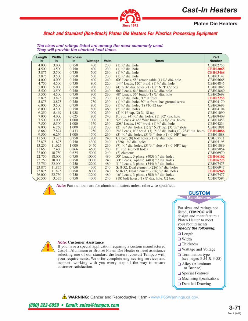
Stock and Standard (Non-Stock) Platen Die Heaters For Plastics Processing Equipment
Length Width Thickness Part in in in Wattage Volts Notes Number 4.000 3.000 0.750 400 230 (1) 5⁄8" dia. hole CBH02755 4.500 3.500 0.750 600 230 (1) 5⁄8" dia. hole CBH03065 3.875 3.500 0.750 500 230 (1) 5⁄8" dia. hole CBH03468 3.875 3.500 0.750 500 230 (1) 5⁄8" dia. hole CBH03147 4.000 4.000 0.750 600 240 60" Leads, 58" armor cable (1) 9⁄16" dia. hole CBH05665 4.750 4.500 0.750 800 220 144" Leads, 120" braid, (1) 5⁄8" dia. hole CBH04845 5.000 5.000 0.750 900 220 (4) 5/16" dia. holes, (1) 1/8" NPT, C2 box CBH01045 5.500 3.500 0.750 600 240 66" Leads, 64" braid, (1) 9⁄16" dia. hole CBH03869 5.500 4.500 0.750 900 230 48" Leads, 36" braid, (1) 9⁄16" dia. hole CBH02698 5.875 3.875 0.750 750 230 (1) 5⁄8" dia. hole, 30° at front CBH02255 5.875 3.875 0.750 750 230 (1) 5⁄8" dia. hole, 30° at front, has ground screw CBH04170 6.000 3.500 0.750 800 230 (1) 5⁄8" dia. hole, (1) #10-32 tap CBH05693 6.000 4.500 0.750 800 460 (2) 5⁄8" dia. holes CBH04104 6.250 5.469 1.938 1000 230 (2) 3⁄8-16 tap, (2) 5⁄16-18 tap CBH01090 7.000 4.000 0.625 800 240 P1 cup, (4) 5⁄16" dia. holes, (1) 1/2" dia. hole CBH08409 7.500 3.000 1.000 1000 110 52" Leads & 48" Wire braid, (2) 9⁄16" dia. holes CBH03453 7.500 5.500 1.000 1350 230 208" Leads, 180" braid, (1) 5⁄8" dia. hole CBH04234 8.000 6.250 1.000 1200 230 (2) 13⁄32" dia. holes, (1) 1⁄8" NPT tap, (3) 13⁄32" slots CBH01091 8.660 7.874 0.433 1250 220 24" Leads, 10" braid, (3) .213" dia. holes, (2) .234" dia. holes CBH04086 9.500 6.250 1.000 1700 230 (3) 13⁄32" dia. holes, (3) 13⁄32" slots, (1) 1⁄8" NPT tap CBH01088 11.500 3.375 0.750 1900 240 C2 box, (8) bolt holes, (1) 5⁄8" dia. hole CBH07511 23.875 11.875 0.750 4300 240 (226) 1/4" dia. holes CBH05195 13.250 11.625 1.000 3450 230 (7) 13⁄32" dia. holes, (3) 13⁄32" slots, (1) 1⁄8" NPT tap CBH01089 21.653 7.480 0.866 4500 280 P1 cup, (6) bolt holes CBH05054 22.000 10.750 0.625 5000 240 (2) elements CBH06970 22.750 18.000 0.750 10000 480 30" Leads, 3-phase, (403) 1⁄4" dia. holes CBH06162 22.750 18.000 0.750 10000 240 30" Leads, 3-phase, (403) 1⁄4" dia. holes CBH06225 22.750 22.000 0.750 12200 480 31" Leads, 3-phase, (344) 1⁄4" dia. holes CBH07475 23.875 11.875 0.750 4300 240 S: 8-32, Dual element, (226) 1⁄4" dia. holes CBH06947 23.875 11.875 0.750 8000 240 S: 8-32, Dual element, (226) 1⁄4" dia. holes CBH06948 26.000 22.750 0.750 13200 480 16" Leads, 3-phase, (305) 1⁄4" dia. holes CBH07477
26.500 3.375 0.750 4000 240 (18) bolt holes, (1) 5⁄8" dia. hole, C2 box CBH07594
For sizes and ratings not listed, TEMPCO will design and manufacture a Platen Heater to meet your requirements. Specify the following:
❏ Length
❏ Width
❏ Thickness
❏ Wattage and Voltage
❏ Termination type (see pages 3-54 & 3-55)
❏ Alloy (Aluminum or Bronze)
❏ Special Features
❏ Machining Specifications
❏ Detailed Drawing
CUSTOM Manufactured
Note: Customer Assistance If you have a special application requiring a custom manufactured Cast-In Aluminum or Bronze Platen Die Heater or need assistance selecting one of our standard die heaters, consult Tempco with your requirements. We offer complete engineering services and support, working with you every step of the way to ensure customer satisfaction.
The sizes and ratings listed are among the most commonly used. They will provide the shortest lead times.
Note: Part numbers are for aluminum heaters unless otherwise specified.
Rev 1 (8-18)

3-4
Used for large volume quantities. Specifically suited for intricate and challenginggeometric shapes, producing quality castings with consistent dimensional accuracyand superior surface finish.Alloy: Aluminum (only)Tooling: Requires a Steel or Cast Iron Permanent MoldMachining: Minimum to no machiningWeight Capacity: Up to 150 pounds depending on shape
Used extensively for medium to high volume quantities. Willaccommodate simple to some irregular shape castings, producinggood dimensional accuracy and surface finish.Alloy: Aluminum (only)Tooling: Requires a Steel or Cast Iron Permanent MoldMachining: Moderate to ExtensiveWeight Capacity: Up to 150 pounds depending on shape
Used for lower volume quantities, prototypes,very large irregular shapes and thermal platens.Alloys: Aluminum, Brass, Bronze and IronTooling: Requires a Wood or Plastic PatternMachining: ExtensiveWeight Capacity: Up to 600 pounds
Casting Process: No-Bake Sand Molds
Casting Process: Tilt-Pour Gravity Feed
There are certain dimensional and/or finish tolerances or geometry that cannot beproduced as cast and must be machined. Tempco offers a full service state-of-the-artmachine shop featuring various types of CNC machine toolsto perform all of the precision machining required—fromsimple to complex contour geometrics, including turningand/or boring, with repeatable accuracy from one machinedcasting to the next. Machinists also build and maintain perma-nent mold tooling for the low pressure and tilt-pour gravity feedcasting processes.
Coordinate Measuring Machine providesprecise measurement of complex parts inprocess or at final inspection.
CNC Machining
CMM Inspection
Casting Process: Low Pressure
Tempco has an in-house Pattern Shopto build and maintain the wood orplastic patterns required to producecastings with no-bake sand molds.
Pattern Shop
Melting CapabilitiesElectric Reverb and Inductionfurnaces are used to minimizegas inclusion into the moltenmetal, thereby producing adenser, higher quality casting.
No one can do itNo one can do it
better than Tempco –better than Tempco –
LET US PROVE IT!
3-5
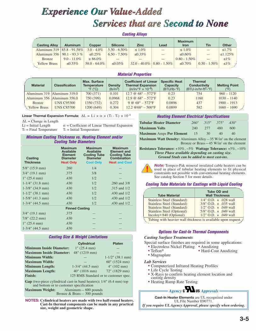
Casting Surface TreatmentsSpecial surface finishes are required in some applications: • Electroless Nickel Plating • Anodizing • Teflon® • Hard-Coat Anodizing • MagnaplateLab Services
• Computerized Infrared Heating Profiles• Life Cycle Testing• X-Rays to confirm heating element location andcasting density• Heating Ramp Rate Testing
Cooling Tube Materials for Castings with Liquid Cooling
Tube OD and Tube Material Wall Thickness Stainless Steel (Standard) 1/4" O.D. × .028 wall Stainless Steel (Standard) 3/8" O.D. × .035 wall Stainless Steel (Standard) 1/2" O.D. × .049 wall Stainless Steel (Optional) 5/8" O.D. × .049 wall Incoloy® 840 (Optional) 1/2" O.D. × .049 wall Tubing with heavier wall thickness is available upon request.
Options for Cast-In Thermal Components
Maximum Maximum Maximum Available Available Element and Element Cooling Tube Cooling Tube Casting Diameter Diameter Combination Thickness Heat Only Cool Only Heat and Cool
5/8" (15.9 mm) .260 1/4 —3/4" (19.1 mm) .375 3/8 —1" (25.4 mm) .430 1/2 —1-1/4" (31.8 mm) .430 1/2 .260 and 3/81-3/8" (34.9 mm) .430 1/2 .315 and 1/21-1/2" (38.1 mm) .430 1/2 .430 and 1/21-5/8" (41.3 mm) .430 1/2 .430 and 1/21-3/4" (44.5 mm) .430 1/2 .430 and 1/2
Finned Casting
3/4" (19.1 mm) .375 — —7/8" (22.2 mm) .430 — —1" (25.4 mm) .430 — —1-3/4" (44.5 mm) .430 — —
Minimum Casting Thickness vs. Heating Element and/orCooling Tube Diameters
Casting Size & Weight Limitations
NOTES: Cylindrical heaters are made with two half-round heaters.Cast-In thermal components can be made in any practicalsize, weight and geometric shape.
Cylindrical PlatenMinimum Inside Diameter: 1" (25.4 mm) —Maximum Inside Diameter: 48" (1219 mm) —Minimum Width: — 1-1/2" (38.1 mm)Maximum Width: — 60" (1524 mm)Minimum Length: 1-3/4" (44.5 mm) 4" (102 mm)Maximum Length: 40" (1016 mm) 72" (1829 mm)Finish: 125 RMS Standard or to customer spec.Gap (two-piece cylindrical cast-in band heaters): 1/4" (6.4 mm) top
and bottom or to customer specificationMaximum Weight: Aluminum— 600 pounds
Bronze & Brass— 300 pounds
Tubular Heater Diameter .260" .315" .375" .430"Maximum Volts 240 277 480 600Maximum Amps Per Element 15 30 40 40Maximum Watt Density: Aluminum Alloy—35 W/in2 on the element
Bronze or Brass—45 W/in2 on the elementResistance Tolerance: +10%, −5% Wattage Tolerance: +5%, −10%
Three Phase available depending on casting size.Ground Studs can be added to most cast-ins.
Note: Tempco-Pak mineral insulated cable heaters can beused in place of tubular heating elements to fit physical constraints not possible with conventional heating elements.See catalog Section 5 for more details.
Heating Element Electrical Specifications
Agency Approvals
Casting Alloys
Maximum Casting Alloy Aluminum Copper Silicone Zinc Lead Iron Tin Other Aluminum 319 85.8 - 91.58% 3.0 - 4.0% 5.50 - 6.50% ≤ 1.0% — ≤ 1.0% — ≤1.7% Aluminum 356 90.1 - 93.3 % ≤0.25% 6.50 - 7.50% ≤0.35% — ≤0.60% — ≤1.125% Bronze 9.0 - 11.0% ≥ 86.0% — — — 0.80 - 1.50% — ≤1%
Yellow Brass ≤0.55% 58.0 - 64.0% ≤0.05% 32.0 - 40.0% 0.80 - 1.50% ≤0.70% 0.50 - 1.50% ≤1%
Material Properties
Cast-In Heater Elements are UL recognized underUL File Number E90771.
If you require UL Agency Approval, please specify when ordering.
Linear Thermal Expansion Formula: ∆L = Li × α × (Tf - Ti) × 10-6
∆L = Change in LengthLi = Initial Length α = Coefficient of Linear Thermal ExpansionTf = Final Temperature Ti = Initial Temperature
Max. Surface Coefficient of Linear Specific Heat Thermal Material Classification Temperature Density Thermal Expansion Capacity Conductivity Melting Point °F (°C) (lb/in3) (in/in/°F × 10-6) (BTU/lb-°F) (BTU-in/hr-ft2-°F) (°F) Aluminum 319 Aluminum 319.0 700 (371) 0.101 12.7 @ 68° – 572°F 0.23 754 960 – 1120 Aluminum 356 Aluminum 356.0 750 (399) 0.0968 12.9 @ 68° – 572°F 0.23 1160 1030 – 1140 Bronze UNS C95300 1350 (732) 0.272 9 @ 68° – 572°F 0.0896 437 1900 – 1913
Yellow Brass UNS C85700 1200 (649) 0.304 12.2 @68° – 500°F 0.0899 582 1660 – 1690

3-52
Cast-In Heaters
Cooling Tube Options
View Product Inventory @ www.tempco.com
Cooling Tube Termination Options for Liquid-Cooled Cast-In Band Heaters
Type FF Flared Seal Fittings Brass flared seal fittings are well adapted for low to medium pressure and resistant to mechanical pullout. Available for 3/8" and 1/2" diameter tubing with SAE 45° flare. Diameter Tubing Thread Part Number 3/8" 5/8"-18 FTG-124-101 1/2" 3/4"-16 FTG-124-104
Type HS Hi-Seal Fittings Hi-seal brass fittings are highly dependable under the most adverse conditions. For reliable and trouble-free service with ease of installation, we strongly recommend hi-seal fittings. Available for 3/8" and 1/2" diameter tubing. Male thread is 1/2" NPT for 1/2" tube and 3/8" tube. Diameter Tubing Part Number 3/8" FTG-118-124 1/2" FTG-118-116
Type RA 90° Copper Elbow 90° copper elbow is brazed to the Cast-In Heater cooling tube extension with additional tube extension for connecting cooling lines with compression and/or flared fittings. Available for 3/8" and 1/2" diameter tubing. If required, specify. Diameter Tubing Part Number 3/8" FTG-127-102 1/2" FTG-127-103
Type RT Cast Brass 90° Threaded Elbow 90° threaded elbow is brazed to the cooling tube extension, providing an easy and quick method for connecting cooling lines. Recommended to be factory installed to assure good braze seals. Available for 3/8" and 1/2" NPT internal threads. If required, specify. Diameter Tubing NPT Part Number 1/2" 3/8" FTG-125-101 1/2" 1/2" FTG-125-102
Type R3 Straight Threaded Copper Fitting Straight threaded fitting is brazed to the cooling tube extensions, providing an easy and quick method for connecting cooling lines. Recommended to be factory installed to assure good braze seals. Available for 3/8" and 1/2" diameter tubing with internal threads. If required, specify. Diameter Tubing NPT Part Number 3/8" 3/8" FTG-131-103 1/2" 3/8" FTG-131-102 1/2" 1/2" FTG-131-101

Tubing Wall Burst Working Pressure Material Part Diameter Material Thickness Pressure (Safety Factor 4) Strength Volume Number (in) (in) (PSI) (PSI) (PSI) (in3/ft)
1/4 304 SS 0.028 11200 2800 75000 0.3547 TUB-101-130 3/8 304 SS 0.035 14000 3500 75000 0.8767 TUB-101-108 1/2 304 SS 0.049 14700 3675 75000 1.5231 TUB-101-110 1/2 304 SS 0.065 19500 4875 75000 1.2903 TUB-101-122
1/2 Incoloy 0.049 17052 4263 87000 1.5231 TUB-111-108
Cast-In Heaters
Cooling Tube Accessories
3-53(800) 323-6859 • Email: [email protected]
Installation Accessories for Liquid-Cooled Cast-In Band Heaters
Stock Tubing for Cooling Lines Cooling Line Tubing can be used to connect the Tempco Cast-In heat/cool bands to the plumbing system of your extruder. Tubing is available in 6'8" lengths for U.P.S. shipments and up to 20' lengths for truck shipments. Barlow’s formula below was used to calculate Working Pressure in the table.
Flexible Teflon® Wire Braided Hose
Flexible Teflon® Wire Braided Hose provides an excellent means of connecting Cast-In Heaters to the extruder plumbing system. This style of hose meets the demands of medium to tight bending radius requirements. The stainless steel braid protects the Teflon® hose from any harsh mechanical conditions that may be present. A variety of brass male and female threaded fittings can be incorporated onto the hose, making it a practical choice for use in conjunction with Tempco’s Style RC Non-Exposed Fittings and other available fittings. Rigid brass adapter fittings as listed below are used to mate the base hose assembly to your existing installation. This allows for the installation of the rigid NPT coupling into the plumbing system and then attaching the swivel fitting on the hose, making assembly relatively easy. Remember to use Teflon® tape or equivalent. Standard Hose: Size 8 (1/2") .405" I.D., .549" O.D. Operating Pressure: 2000 PSI Burst Pressure: 8000 PSI
Part T1 T2 Number 1⁄2" male 37° SAE flare 1⁄2"-14 NPT male FTG-161-103 1⁄2" male 37° SAE flare 1⁄2"-14 NPT female FTG-161-102 1⁄2" male 37° SAE flare 3⁄8"-18 NPT male FTG-161-104
1⁄2" male 37° SAE flare 3⁄8"-18 NPT female FTG-161-105
Adapter Fittings for Flexible Teflon® Wire Braid Hose
Rigid brass adapter fittings are used to mate the base hose assembly to your existing installation.
The standard hose assemblies are supplied with 1/2" female 37° SAE flare swivel
style crimped-on fittings. The hose assemblies can be ordered in 6" increments starting at 18" minimum. Fitting material is Brass.
Part Number* WHT05
*Complete the Part Number with length of hose in 6" increments starting at 18" (018).
Standard lead time is 2 weeks or less.
Ordering Information
Maximum Working Pressure (PSIG) = 2 × Material Strength (PSI at Room Temperature) × Wall Thickness of Tube (in)
OD of Tube (in) × SF (Safety Factor of 1.5 to 10 depending on application)
Rev 1 (8-28-2018)
3-54
Cast-In Heaters
Electrical Termination Options
View Product Inventory @ www.tempco.com
Standard Tubular Heater Terminations for Cast-In Heaters
Select the termination style that meets your requirements for space, accessibility and reliability.
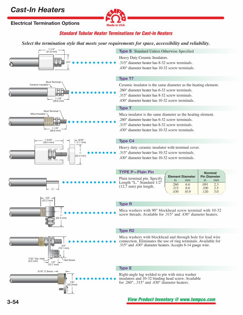
TYPE P—Plain Pin
Plain terminal pin. Specify Length “L.” Standard 1/2" (12.7 mm) pin length.
Nominal Element Diameter Pin Diameter in mm in mm .260 6.6 .091 2.3 .315 8.0 .100 2.5
.430 10.9 .120 3.0
Type S Standard Unless Otherwise Specified
Heavy Duty Ceramic Insulators. .315" diameter heater has 8-32 screw terminals. .430" diameter heater has 10-32 screw terminals.
Type T7
Ceramic insulator is the same diameter as the heating element. .260" diameter heater has 6-32 screw terminals. .315" diameter heater has 8-32 screw terminals. .430" diameter heater has 10-32 screw terminals.
Type T
Mica insulator is the same diameter as the heating element. .260" diameter heater has 6-32 screw terminals. .315" diameter heater has 8-32 screw terminals. .430" diameter heater has 10-32 screw terminals.
Type C4
Heavy duty ceramic insulator with terminal cover. .315" diameter heater has 10-32 screw terminals. .430" diameter heater has 10-32 screw terminals.
Type R
Mica washers with 90° blockhead screw terminal with 10-32 screw threads. Available for .315" and .430" diameter heaters.
Type R2
Mica washers with blockhead and through hole for lead wire connection. Eliminates the use of ring terminals. Available for .315" and .430" diameter heaters. Accepts 6-14 gauge wire.
Type E
Right-angle lug welded to pin with mica washer insulators and 10-32 binding head screw. Available for .260", .315" and .430" diameter heaters.
Cast-In Heaters
Electrical Termination Options
3-55(800) 323-6859 • Email: [email protected]
Standard Tubular Heater Terminations for Cast-In Heaters
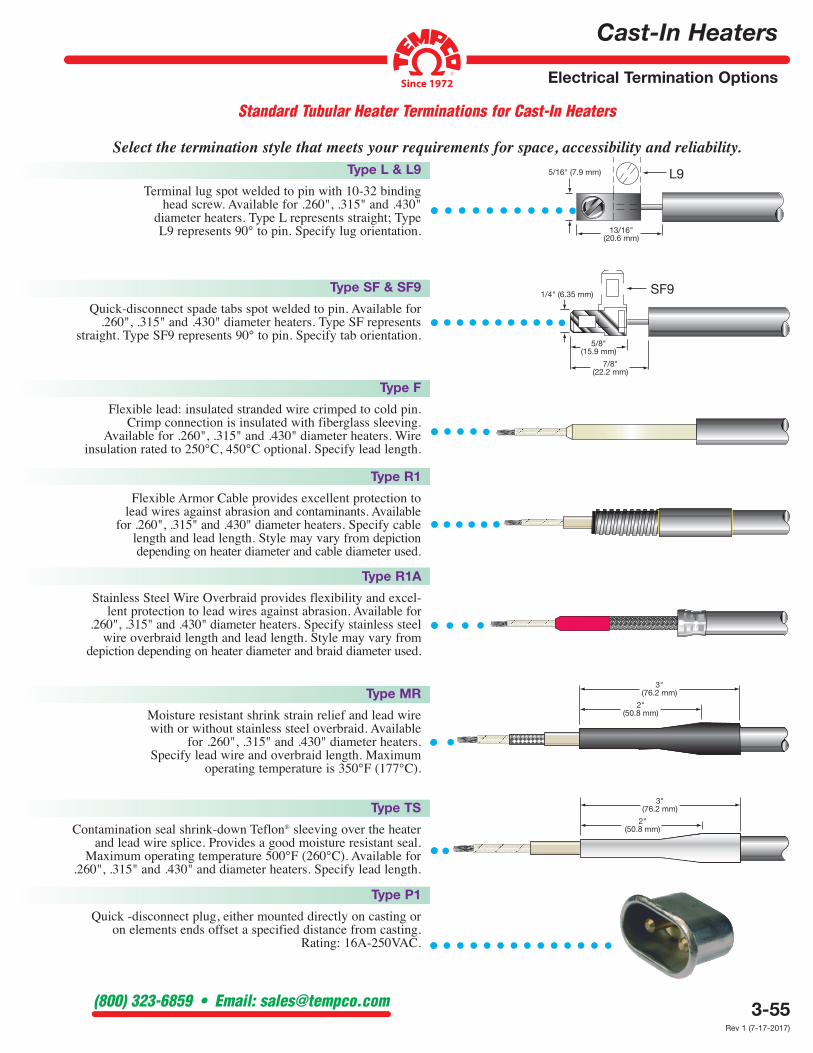
Select the termination style that meets your requirements for space, accessibility and reliability.Type L & L9
Terminal lug spot welded to pin with 10-32 binding head screw. Available for .260", .315" and .430"
diameter heaters. Type L represents straight; Type L9 represents 90° to pin. Specify lug orientation.
Type SF & SF9
Quick-disconnect spade tabs spot welded to pin. Available for .260", .315" and .430" diameter heaters. Type SF represents
straight. Type SF9 represents 90° to pin. Specify tab orientation.
Type F
Flexible lead: insulated stranded wire crimped to cold pin. Crimp connection is insulated with fiberglass sleeving.
Available for .260", .315" and .430" diameter heaters. Wire insulation rated to 250°C, 450°C optional. Specify lead length.
Type R1
Flexible Armor Cable provides excellent protection to lead wires against abrasion and contaminants. Available
for .260", .315" and .430" diameter heaters. Specify cable length and lead length. Style may vary from depiction depending on heater diameter and cable diameter used.
Type R1A
Stainless Steel Wire Overbraid provides flexibility and excel-lent protection to lead wires against abrasion. Available for
.260", .315" and .430" diameter heaters. Specify stainless steel wire overbraid length and lead length. Style may vary from
depiction depending on heater diameter and braid diameter used.
Type MR
Moisture resistant shrink strain relief and lead wire with or without stainless steel overbraid. Available
for .260", .315" and .430" diameter heaters. Specify lead wire and overbraid length. Maximum
operating temperature is 350°F (177°C).
Type TS
Contamination seal shrink-down Teflon® sleeving over the heater and lead wire splice. Provides a good moisture resistant seal.
Maximum operating temperature 500°F (260°C). Available for .260", .315" and .430" and diameter heaters. Specify lead length.
Type P1
Quick -disconnect plug, either mounted directly on casting or on elements ends offset a specified distance from casting.
Rating: 16A-250VAC.
Rev 1 (7-17-2017)
3-56
Cast-In Heaters
Electrical Termination Housings
View Product Inventory @ www.tempco.com
General Purpose Terminal Protection Boxes For Cast-In Heaters
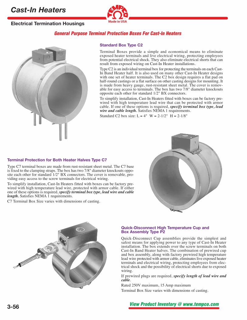
Standard Box Type C2
Terminal Boxes provide a simple and economical means to eliminate exposed heater terminals and live electrical wiring, protecting employees from potential electrical shock. They also eliminate electrical shorts that can result from exposed wiring on Cast-In Heater installations. Type C2 is an individual terminal box for protecting the terminals on each Cast-In Band Heater half. It is also used on many other Cast-In Heater designs with one set of heater terminals. The C2 box design requires a flat pad on half-round castings or a flat surface on other casting designs for mounting. It is made from heavy gauge, rust-resistant sheet metal. The cover is remov-able for easy access to terminals. The box has two 7/8" diameter knockouts opposite each other for standard 1/2" BX connectors. To simplify installation, Cast-In Heaters fitted with boxes can be factory pre-wired with high temperature lead wire that can be protected with armor cable. If one of these options is required, specify terminal box type, lead wire and cable length. Satisfies NEMA 1 requirements. Standard C2 box size: L = 4" W = 2-1/2" H = 2-1/8"
Quick-Disconnect High Temperature Cup and Box Assembly Type P2
Quick-Disconnect Cup assemblies provide the simplest and safest means for applying power to any type of Cast-In Heater installation. The box extends over the screw terminals on both Cast-In Band Heater halves. The combination of prewired cup and box assembly, along with factory prewired high temperature lead wire protected with armor cable, eliminates live exposed heater terminals and electrical wiring, protecting employees from elec-trical shock and the possibility of electrical shorts due to exposed wiring. If prewired plugs are required, specify length of lead wire and cable. Rated 250V maximum, 15 Amp maximum Terminal Box Size varies with dimensions of casting.
Terminal Protection for Both Heater Halves Type C7
Type C7 terminal boxes are made from rust-resistant sheet metal. The C7 base is fixed to the clamping straps. The box has two 7/8" diameter knockouts oppo-site each other for standard 1/2" BX connectors. The cover is removable, pro-viding easy access to the screw terminals for electrical wiring. To simplify installation, Cast-In Heaters fitted with boxes can be factory pre-wired with high temperature lead wire, protected with armor cable. If either one of these options is required, specify terminal box type, lead wire and cable length. Satisfies NEMA 1 requirements. C7 Terminal Box Size varies with dimensions of casting.
Cast-In Heaters
Electrical Termination Housings
3-57(800) 323-6859 • Email: [email protected]
Terminal Protection Boxes for Cast-In Heaters
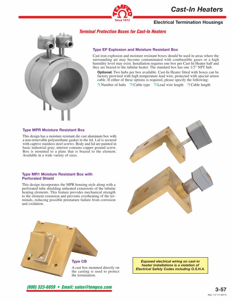
Type EP Explosion and Moisture Resistant Box
Cast iron explosion and moisture resistant boxes should be used in areas where the surrounding air may become contaminated with combustible gases or a high humidity level may exist. Installation requires one box per Cast-In Heater half and they are brazed to the tubular heater. The standard box has one 1/2" NPT hub.
Optional: Two hubs per box available. Cast-In Heater fitted with boxes can be factory prewired with high temperature lead wire, protected with special armor cable. If either of these options is required, please specify the following: ❒ Number of hubs ❒ Cable type ❒ Lead wire length ❒ Cable length
Type MPR Moisture Resistant Box
This design has a moisture resistant die cast aluminum box with a non-removable polyurethane gasket in the lid. Lid is secured with captive stainless steel screws. Body and lid are painted in basic industrial gray; interior contains copper ground screw. Box is mounted to a plate that is brazed to the element. Available in a wide variety of sizes.
Type MR1 Moisture Resistant Box with Perforated Shield
This design incorporates the MPR housing style along with a perforated tube shielding unheated extensions of the tubular heating elements. This feature provides mechanical strength to the element extension and prevents overheating of the ter-minals, reducing possible premature failure from corrosion and oxidation.
Exposed electrical wiring on cast-in heater installations is a violation of
Electrical Safety Codes including O.S.H.A.
Type CB
A cast box mounted directly on the casting is used to protect the termination.
Rev 1 (7-17-2017)
3-74
Cast-In Heaters
Installation Recommendations
View Product Inventory @ www.tempco.com
Installation Recommendations for Cast-In Thermal Components
Installation
1. Allow sufficient space for thermal expansion. The amount of space required depends upon the Cast-In Heater size, operating temperature and alloy.
2. Surface being heated must be free of any foreign materials and have a smooth finish.
3. Make sure that the casting is properly seated. The clamping devices used should be tightened down to the correct recommended torque. After initial heat-up, retighten fasteners to the correct recommended torque.
Recommended Torque: 10 ft-lb for 1/4–5/16 bolts, 20 ft-lb for 7/16–5/8 bolts
5. Thermal insulation can be used to reduce heat losses. 6. Avoid mounting heaters in an atmosphere
containing combustible gases and vapors unless specifically manufactured for use in such conditions.
7. Liquid Cooled Cast-In Heater fittings must be securely tightened to prevent leaks.
8. To prevent overheating and heater failure, adequate temperature controls should be installed. For assistance in selecting temperature controls and thermocouples, see Tempco’s (in-stock) complete line of Plug-In type Proportional Temperature Controls for heating and cooling applications in Section 13. Also see the listing on standard and hot melt thermocouples in Section 14.
Wiring
1. For connections at the heater terminals, use high temperature nickel conductor or nickel clad copper lead wire or alloy bus bar. Keep all electrical connections properly protected to eliminate electric shock to machine operators.
2. Heaters of equal wattage and voltage can be connected in series for higher voltage.
3. Heater installations must be properly grounded to eliminate electric shock hazard, and wiring must comply with electrical codes.
4. Always have a qualified electrician perform all wiring and connection of heaters and control compo-nents. Terminals must be tightened to the correct torque (2.5 ft/lb for terminal connections).
CAUTION: Castings are not designed to be lifted or carried by the terminations or leads.
Operation
1. It is recommended to slow start the process during first use.
2. Do not operate above rated voltage. Excess voltage will result in heater failure.
3. Do not operate Cast-In Heaters above recommended temperatures. Heater temperature must be monitored and controlled. Use of over-temperature T/C is strongly recommended for higher temperature applications. Excess temperatures will result in heater failure and/or melting.
4. Electrical terminals must be kept free of contaminants, as spillage of plastic, water, oils, and their vapors can cause electric shorts, resulting in heater failure.
5. Liquid Cooled Cast-In Heaters must not be cycled to operate simultaneously. Thermal stresses may result in shorter heater life.
6. The water used on Liquid Cooled Cast-In Heaters must be properly treated. Hard water contains corrosive media that will contaminate the tubing, producing stress corrosion cracks and resulting in shorter heater life. Presence of minerals in water can cause clogged tubes that can result in poor heat transfer and eventually heater failure.
Maintenance
1. Never perform any type of service on heaters prior to disconnecting all electrical power.
2. To ensure good surface contact, periodically check clamping. Retighten clamping to the correct torque when required.
3. Repeat cycling of temperature controls can indicate poor surface contact or a burned-out heater.
4. Heater terminals must be kept free of plastics, oil, water, and any other foreign matter. As these materials carbonize, they create electrical shorts.
5. Heater terminal electrical connections must be kept tight. Loose connections can overheat and eventual destroy the connection or the heater terminal.
6. Water lines must be periodically checked for leaks. Water on heater terminals can be detrimental to the entire heating system.
7. Thermocouples must be kept free of contaminants and be checked for good response to temperature changes. Our recommendation is to change them periodically, as a bad thermocouple can be the cause of destroying an entire heating zone.
Tempco Cast-In Heaters will provide long life and dependable, trouble-free service if properly installed, operated, and maintained as per the following recommendations:
Exposed electrical wiring on cast-in heater installations is a violation of
Electrical Safety Codes including O.S.H.A.
Complete Your Installation With Accessories Available From Stock
Accessory Catalog Section
✴ Stainless Steel Tubing and Fittings For Cooling Lines 3 ✴ Pressure Transducers and Rupture Disks 12 ✴ Temperature Controllers 13 ✴ Temperature Sensors, Thermocouple Wire, Jacks & Plugs 14 ✴ High Temperature Lead Wire & Fiberglass Tape,
Ceramic Terminal Covers and Electric Plugs 15
▼▼▼▼ ▼▼▼▼ ▼▼▼ ▼▼▼▼ ▼▼▼▼ ▼▼▼
Note: See page 16-11 for Wiring Diagrams and page 15-2 for lead wire selection