Embed Size (px)
Citation preview

THE CASSELL. BOOK OF THE
AUSTIN A 3 5 (1957-9)

CASSELL MOTORING SERIES
B Y ELLISO N HAWKS
1. Th e Cassell Book of the Austin A 40 Devon (1947-52)2. Th e Cassell Book of the A ustin T en (1939-47)3. The Cassell Book of the Ford' Prefect' (1938-53)4. Th e Cassell Book of the Ford' A nglia ' (to 1953)5. The Cassell Book of the Ford' Popular' (from 1953)6. Th e Cassell B ook of the Austin A 40 Somerset (1952-4)7. Th e Cassell Book of the Ford' Consul ' (1951-6)8. T he Cassell Book of the Ford' Z ephyr ' and ' Zodiac' (1951-6)9. T he Cassell Book of the Austin A30 • Seven ' (1951-6)
10. Th e Cassell Book of the Ford' N ew A nglia' (1953-7)11. Th e Cassell Book of the Standard E ight (1953-5)12. Th e Cassell Book of the M orris M inor (Series MM)13. Th e Cassell Book of the A ustin A 35 (1957-9)14. Th e Cassell B ook of the Ford' Ne w Pref ect' (after 1953)16. The Cassell Book of the Vauxhall Wyve rn (1951-7)
BY IA N N IC K OLS
15. Th e Cassell Book of the H illman M in x
The Cassell .Bookof the
AUSTIN A35(195 7-9)
by
ELL ISON HAWKS
CASSELL LONDO N

CASSELL & COMPANY LTD
35 Red Lion Square . London weiand at
MELBOURNE • SYDNEY ..' TORONTO • CAPE TOWN
JOHANNESBURG • AUCKLAND
CONTENTS\
INTRODUCING THE AUSTIN A35
PAGE
I
© Ellison Hawks 1960
First published 1960
13
Set in 10 pt. Old Styleand Printed in Grea t Britain by
Butler & Tann er Ltd., Frome and LondonF.1259
II FOR THE BEGINNER
III GENERAL MAI NTENANCE;AND TYRES
IV STEERING GEAR
V SUSPENSION
VI BRAKING SYSTEM
VII ENGINE
VIII CARBURETTOR
IX FUEL PUMP
X COOLING SYSTEM
X I TRANSMISSION
XII ELECTRICAL SYSTEM
XIII LUBRICATION
RECOMMENDED LUBRICANTS
FAULT FINDING CHART.
WIRING DIAGRAM
I NDEX
v
BODY, WHEELS
9
29
5I
59
66
80
I06
n6
I25
I39
I 55
I93
2I7
2I8
220
223
PREFACE
T HE PURPOSE OF THIS BOOK is to describ e insimple language how the owner-driver may obtain
the best possible satisfaction from his Austin A35.The inherent reliability of modern cars may sometimes
tempt owners to neglect the routine maintenance so necessary if the best performan ce is to be obtained. Neglectreduces efficiency and causesboth appearance and mechanismto deteriorate, thus rendering a breakdown on the road moreprobable. The efficient running, reliability and length oflife of any car are determined by the attention given to it.
This book is written for the owner who takes pride in theappearance of his car, and who is able to devote the relatively small amount of time necessary to maintain it infirst-class order. The jobs involved are for those who subscribe to the ' Do it Yourself ' vogue .
Minor running adjustments may be required from timeto time. The old proverb that' a stitch in time sav es nine'is very true, for neglect may lead to expense that mighthave been avoided had the owner been familiar with somesmall routine attention.
Detailed instructions are given so that lubrication mayhe carried out regularly and thoroughly. A section has beendevoted to overhauling to the extent possible by the averagemechanically-minded owner. When extensive attention isnecessary, however, it is generally advisable to allow yourlocal Austin dea ler to do the heavy work. He has betterfaciliti es to handle such jobs. His staff is thoroughlyfamiliar with all Austin models, can diagnose symptoms offailure and suggest remedies. The Austin Motor Co. Ltd.give a course of training and instructi on to selected
vn
Vlll PREFACE
mechanics from dealers' st affs, and owners are advised tomake use of the expert knowledge thus gained.
Another point to bear in mind is that the Company hasgained considerable experience from years of research.Naturally, it stresses that only genuine Austin replacementparts are used when necessary.
A few readers may feel that some of the information givenis elementary. Experience shows, however, that often theminor point is the one that is overlooked , due to lack ofknowledge of its importance or unfamiliarity with a particular feature. This can give rise to inconvenience due todelay on the road , as well as expense in upkeep.
This book is not published by the Austin Motor Co. Ltd. ,who have no responsibility for it . At the same time Iwould tender my thanks to them for the assistance theyhave given, and for supplying illustrations and technicaldata.
ELLISON H AWKS
Vi ctoria H ouse.Southport
"
CHAPTER I
INTRODUCING THE AUSTIN A35
T HE AUSTIN A35 is another outst anding example ofa popular light car designed to give comfortable trans
port at low-running cost. Equipped with the most up-todate developments, it also has the commodious luggagespaceso necessary for touring. Suspension incorporat es semielliptic leaf-springs at rear , and independent front wheelcoils and wishbones at front. The driver has a clear viewof the road ah ead , and control s fall readily to hand.
There are two touring models-the two-door and four door saloons, and three other types-the A35 Van , Pick-upand Countryman.
Mechanical design follows typical Austin practice in thatthe car is simple to maintain. Construction is such that itcan be relied on to give many years of care-free motoring.Driver 's bucket seat is adjustable to five positions andpassenger 's seat to three positions, thus meeting requirements of individual drivers and passengers and ensuringthat long-distance travelling imposes a minimum offatigue.
Once the car is in use it is the responsib ility of the ownerto keep it in good condition by careful attention to lubrication and maintenance. The main components are describedbriefly in the general specification given below.
EngineEngine, identical in all models, is of the usual four
cylinder four-stroke type. Bore, 2'48 in. (62'9 mm.) andstroke 3-00 in. ('76 mm.). Capacity: 57'82 cu. in. (948 c.c.)giving 34 b.h.p. at 4,750 r.p.m. with a maximum torque of50 lb. zft . at 2,000 r.p .m. Compression ratio: 8'3 to I.
Cylinders are cast en bloc and, with upper half of thecrankcase, provide a rigid mounting for th e three mainbeatings 'carrying the counterbalanced crankshalf. Thisconstruction ensures the least possible vibrat ion.
A detachable cover gives ready access to overhead-typeI

z THE BOOK OF THE AUSTIN A35 INTRODUCING THE AUSTI N A35 3
FIG. I.-LE ADI NG DIME N SIO NS OF T H E A35
Oil is also supplied under pressure to the crankshaftmain bearings, big-end bearings, camshaft, and overheadvalve gear. A special arrangement is made for the frontcamshaft bearing to provide oil to the timing cham. Thepump it self has a filter that prevents the ingress of larger
particles of carbon or other foreign matter. The externalfilter takes care of small particles in suspension in the oilt ream.
The oil sump has a capacity of 6 pints . When the oili lter has been renewed an extra pint will be required to
I 8
ft. in.Overall height N 4 IItOverall length 0 II 4iOvera ll width . 4 7tScu t tle wid th . . . . 3 9~Body width bet ween cen tre
pillars. . . 3 IIRear sea t width . . . 2 IIiBody wid th ove r rear sea t 3 roWhee lbase • . 6 7;Track, front (a t ground
level) . . 3 9tTrack, rear. . 3 8iGrou nd clearance 61Turning circle. " 35 0Lu ggage compartment:
Heigh t of openingMinimum wid th of
opening 2 61Depth . . . . . . I 6
Approximate weigh t un-laden (including oil andwater, less fuel) . 13i cwt,
5
I I 5!
I 7!
ft . in .
A { 2 10Pe,rial to sea t squab .
Steer ing wheel to sea t t31 ~
sq uab . B I 2
Distance be tween sea ts C I ~
Rear sea t cush ion depth D I 5!Heigh t over rear sea t E 2 II!Max imum int erior height F 4 I
Height over fron t seat G 3 IHeight of door opening H 3 I !Front sea t cushion
depth . .Fron t seat cush ion
wid th . . . . .Steerin g wheel to seat
cushion . . . . JFront sea t cushi on
abo ve floor . , . K I 2
Rear sea t cus hionabove floor . . . L I I !
Height, floor to ground M ro;
push-rod opera ted valves. Oil seals are fitted to pre vent oilreaching the combustion heads by way of the valve guides .
The camshaft , which is on the near side of the engine,is driven by a duplex roller chain. It incorporates a specialrubb er insert in the sprocket to ensure silent running andcorrect chain tension. The overhead va lves have a simp lescrewed rocker adjustment. The totally enclosed valvemechanism is lubricated from the engine, thus reducingad justment to a minimum. The rocker shaft bearings arelubricated under pressure from the oil pump.
The overhead-valve rockers have a passage along whichoil is fed to an outlet at the spherical ball-end , this latterfitting into the correspondingly shaped end of the pushrod. Oil at this point naturally obviates wear but also,as it is delivered under pressure, it t akes up the smallcleara nce' purposely provided between the end of the va lveand the rocker tip thus minimizing valve noise.
The four I -sect ion connecting rods carr y gudgeon pinslocked in the little-end eyes by clamp bolt s. As the gudgeonpins are not free to turn in the connecting-rod little-endeyes, it is unnecessary to provide circlips or pads to t akecare of endwise pin movement.
The big-end bearings are provided with small h<;>les topermit oil to reach the cylinder walls, thus assun ng anadequa te supply of lubricant under all operat ing conditionsand particularly when th e engine is cool.
Th e dish-headed pistons are of a special aluminium alloywith alumite sur face to ensure efficient lubrication, theskirts being of the split t ype. There are four rings : ~he
uppermost is a plaiD; compression rin g, the second .and .thlrdare taper compression rings, and the bottom n ng IS anoil-controlled slotted scraper ring.
Lubrication by pressure is developed by a submergedtyp e oil pump situated in a housing that cont:=ti?-s two intermeshing gears driven from the camshaft. OllIS constantlypassed through an external filter mounted on the offsi~e
of the engine and cleaned by a filter element before Itreturns to the sump. Should this filter become completelychoked, the oil flow to the various bearings would not beinterrupted although the purpose of the filter would belost . Instead of the oil passing through it to be cleaned,the filter would be by-passed.

THE BOOK OF THE AUSTIN A3S INTRODUCING THE AUSTIN A3S 5compensate for the amount normally retained in the filterand circulating pipes. To enable the engine-oil level tobe readily determined, a dip-stick is fitted on.the offsideof the engine near the distributor .
The engine and gearbox, bolted t ogether t o form a singleunit, are mounted on rubber pads. Thi s type of moun tingnot only insulates sound but also absorbs vibra tion fromthe power unit . The front engine mountings also incorporate rubber pads to control undue movement that maytend t o occur under certain conditions.
The water in the cooling syst em is circulated by acentrifugal pump built into the front of the cylinder blockand driven by a V-type belt from the crankshaft pulley.It is controlled by a thermostat fitt ed in the water outletat the front end of the cylinder head. Its working isentirely automatic with a normal operating temperatureof 1640F.
The radiator incorporates a chamber in the header tankto prevent loss of water due to expansion. A fan , mountedon the pump shaft, draws air through the radiator core toassist cooling. The water capacity of the cooling systemis 8! pints.
Two drain t aps ar e provided to allow the system to bedrained in frosty weather if an anti-freeze soluti on is not used.
Carburettor ,The Zenith carburet tor (Model 26 VME) of down
draught type on near side of engine, has a choke for easystarting. Fuel fed by a pump opera ted by the camshaftis drawn from the tank mounted at the rear of the car ,The fuel capacity of the t ank is 5£ gallons.
The A.C. oil-wetted air cleaner fitted to the carburettoris efficient in reducing noise due to the rush of air enteringthe carbure ttor particularly when accelerating. It alsohas the advantage of preventing grit from being drawninto the engine where it can cause premature wear. Apipe leads from the valve cover to the air cleaner so that oilfum es from the engine do not reach the body. Inst ead,they are drawn into the engine by the natural suctionat thi s point.
An electric-type petrol contents gauge is mounted onthe dashbo ard so that the driver can see at a glance the
level of the fuel in the tank. This gauge will only readwhen the ignition is ' on ' .
ClutchThe Borg and Beck single dry-plate clutch has a spring
loaded friction disc giving smooth engagement . Theclutch-release bearing is of the carbon type, requires nolubrication, and will operate indefinitely without attenti onprovided that the clutch pedal free movement is correctlyadjust ed. This linkage is so designed that little effort. isrequired to free the clutch . When necessary, the i in ,
adjustment of the free-pedal travel is a simple matter.
GearboxThe gearbox, of unit construction with the engine, is
bolted directly to the flywheel housing. It has four forward speeds and reverse with remote central lever control.
'There is synchromesh engagement on second, third andtop gears , making gear-changing easy an d effortless.
The gears are of the helical type, ensuring a considerabledegree of silence as well as great strength. A pair of helicalgears t ransmit drive to speedometer through a flexiblecable. This arrangement ensures automatic lubrication fordrive gears as well as obviating the need for any ad justment .
Oil capacity of gearbox ,: 2! pints.
Transmission " 'I,
The drive from the gearbox to the rear axle is by anopen-type propeller shaft at each end of which is a HardySpicer universal joint with needle roller bearings. At thefront end of the shaft is a splined member tha t engages,in a correspondingly splined part of the universal joint.With the rise and fall of the rear axle, the propeller shaftis free to move slightly at the splined end, so taking upthe cha nge in length that occurs due to this movement.
Rear Axle ',. l r
A 'banjo '-type housing construction result s in a rear. le that is rigid yet light. The axle shafts are o~ thehr e-quarter floating type, splined at their inner ends and
" , iJy detachable. On the axle-housing nd the hubs
6 THE BOOK OF THE AUSTIN A3S INTRODUCING THE AUST IN A35 7
are mounted on ball races. A flange formed on each axleshaft outer end is bolt ed to th e hub to imp art the finaldrive. '
The crown wheel and pinion are of spiral bevel design,the pinion being moun ted on taper roller bearings. Thedifferenti al is of the two-pinion type and moun ted on asingle centre spindle. The cage is mounted on combinedjournal and thrust ball bearings, prov ision being made formesh adjustment.
The oil capacity of the rear axle is I t pints.
Braking SystemThe Lockheed br aking sys tem employs hydrauli cally
operated leading brake shoes on the fron t wheels andmechani cally operated brake shoes on the rear. Themechanical linkage is actuated by means of a hydrauliccylinder and stirrup mount ed under the body. A pullup type of han dbrake operates dir ectly on the mechanicallinkage to the rear wheels.
The front wheel brakes consist of two leading shoes.Those of the rear hav e one shoe of the t railing type andthe other leading. This combinat ion- two leading shoes atthe front and single leading at the rear-results in extremelyefficient br aking.
Brake-shoe lining wear is taken up by a simple means.The br ake shoes can readily be examined by drawing offthe brake drums, these being so mounted that the hubs donot have to be dismantled for this purpose.
SteeringThe steering, of the cam-gear type, is a self-contained
unit of extreme simplicity with a ratio of 12: 1. Th esteering box is mounted forward of the toeboard andpro vides a short steering column of great rigidity.
BodyThe body of the A35 is essentially a single un it and
does not require a chassis frame. The engin e, gearbox,and front and rear suspen sion units are anchored to thereinforced body shell. This is made up of six major sections welded and riveted together to form a box sectionof great rigidity .
The body it self is of all-steel uni tary construction wit hfully st ressed skin. Its number will be found on the topleft of the scutt le in the engine compartment .
Suspension at the fro~t is i!1depend er:t f.or each ;vh~el.This is achieved by. COlI spn ngs and WIsh-bone WIthmembers of unequal length, a compression spring beinginterp osed . A double-acting Arm strong hydraulic pist ontyp e shock absorber is incorpora ted on each side in theup per wish-bone member. . . . .
The rear road spr ings , of the multi-leaf semi-elliptictyp e, are under-slung beneath . the axle h~lUsing .t o give alow body mounting. The spring-eyes, WIth their rubberbushed shackles, do not require any lubrication. Th elubricators at the centre of the upper rear shackles shouldperiodically be given att~ntion . . .
An anti-roll bar-a device to limit body roll when cornering- is fitted to the rear axle. It consists of a U-shapedsteel bar mounted so that its two arms point to the rear.E ach arm is bolt ed to the shock-absorber lever arm andthence connect ed, through rubber-bushed links, to theaxle housing. A fuller description of this ingenious deviceis given on page 60. . .,
The four hydraulic shock absorbers assist in dampingout roa d shocks and in conjunct ion with the independentfront suspension help t o give a comfortable ride.
The pressed-steel road wheels hav~ ventilati~n ~lotspierced in their discs ad jacent to the nm to permit arr tocool the brake drums.
E xtra low-pressur e 52'0 -13 tubeless tyres are fitted.
Electrical EquipmentLighting and start ing equipment is of the I 2-volt t ype.
The 43-amp. hr. battery (at zo-hr.. r~te) is .fitted on. theengine side of the bulkhead where It IS readily accessible.
The generator is vent ilated to pr event it becoming too11 t. Output is automat ically controlled by a regulat or0. orc1ing to the requirements of the system.
Th starter motor is mounted on the off side of the engine,L t ing it as required by a small pinion automatically
I I )\1 rht into and out of mesh with the flywheel ring gear.'I II · ignition system is of the high-tension type, with

8 THE BOOK OF THE AUSTIN A3S
distributor and rotor readily accessible both for contact-breaker gap setting and for timing. .
Ignit ion switch, mounted on the dash, is locked ' off 'when the key is removed.
Automatic advance and retard are controlled centrifugally by the engine speed. A vacuum-assisted deviceenables an appropriate degree of advance to be madeaccording to the load.
The lighting equipment consists of two 4zl36-watt headlamps mounted in each fron t wing, and two 6-watt sidelamps mounted on top of the wings. The switch for thelights, l~cated on the ~ight-hand side of the st eeringcolumn, IS turned clockwise to the first notch for the sideand rear lights, and to the second notch to dip the headlights. The third notch brings the headlights to the normalfull-ahead position. .
A warning light on the facia panel is illuminated whenthe headlamp beams are in the full-ah ead position. Thisserves as a warning that on-coming traffic may be dazzledand that the headlamps should be dipped.
The twin stop and tail lamps are automatically switchedon when the brake ped al is depressed. '
Under the facia panel is a cour tesy light to illuminate thecar floor when the doors are opened. ., . '
The in.strument panel is lit .by concealed interior lampsonly ~vaI~able when the side lights or headlights are in use.. Switching on of these panel lights indicates that ,the
sidelamps have also been switched on . .There is.a warning lamp t o show the driver if the-.ignition
has been left on with the engine stat ionary. It also showsif the generator is not charging . . .
The trafficato rs, of the solenoid-opera ted typ e, are con..~rolled from a switch to the right of the steering wheelin early models, and at the centre of the dashboard iiilater ' models. .
The windscreen wipers are electrically operated and havea separate control. .. . '
Th e heater , when fitted, circulates heated air by meansof a .small electric fan controlled from the facia panel.
.i'Ihe electric horn is controlled from the centre of th este.ering wheel and operates independently of the ignitionswitch, ,. .
CHAPTER II
FOR THE BEGINNER
T E FOLLOWING HINTS are given in the hopethat they may be helpful to a new dri ver who
it is a sumed is already familiar with the rudiments ofroad curtesy. There are not only. the niceties of drivingth a t are to be learned from expenence , but also variousdctrirn ntal practices th~t may result in reducing potentialperf rrnance and duration of the normal life of the car.
This chapter describes some of the correct methods ofpro dure. If at the outset you are not clear about thehabits ~o avoid, you may train yoursel~ to adopt a techniquethat will not only enable you to obtarn the best from yourA35 but will also avoid undue mechanical wear and tear.
Although an inanimate object a car requires to becons i nti<;>usly loo.ked aft~r as much .as a horse or a dog .By f llOWlI~g the instructions you WIll find that you areamply repaid fo.r care and attenti on by enjoying the manythousands of miles of pleasurable motoring that lie ahead.
First let us refer to the instruments and controls illustrat 1 in Fig-s. z and 3, by sitting in the car with therel~van t illustrations available. It is important to be ableto find, and use, an y appropriate control without hesitat ion .
The id al to attain is to be able to place the hand orfoot .on the control desired without the necessity of removm g the eyes from the road. Obvious as this ad vicemay seem, it is surprising how many drivers find it necessary to look for any particular control they want . In thecongested state of the roads at the present time andbearing in mind the normal road speed of traffic: youm"lst. have sup~~me confidence not only in your car bu talso In your ability to operate t.he various cont rols swiftlyand automati~ally. . At night you cannot expect to cont rolyo,?r car efficiently If you mus t have the interior top lightswitched on so that you can dete rmine the position of thegear or brake levers. It is also important to know howthe control should be operated in order to give th necessary
B 9

I O THE BOOK OF THE AUSTIN A3S FOR T HE BEGINNER II
F I G. 2.-FACI A PANE L
I Choke Control. 2 Dir ecti on Indica tor Switch . 3 Headla mp Beam Warn ing Light .4 Oil Pr essure Warning Light. 5 Hea ter Motor Switch. 6 Win dscreen Wi per Switch.7 Air Control. 8 Demist er/Defrost cr, 9 Panel Light Switch . 10 Ignition Switch.II F uel Gauge. 12 Ignition Warn ing Light . 13 Mileage Record er . 14 Speedometer.
15 Star ter Control
r esults . B y carefully practising , you will increase yourability to control the car on the road by day or nightuntil the operation becomes automatic.
Within certain limits the posit ions of both front seatscan be adjusted near er to or farther from the steeringwhee l by operati ng a hand lever an d catch on the outerside of eac h seat. The seats may be moved an d lockedin the desired positions when the control is released .
The adjustment of the dr iver's sea t should be such thatboth the clutch and foot-brake pedals can be opera t edwith ease . Mak e sure that the lockin g device does ac tua llyengage one of the slots in the ru nners, otherwise the seatmay move rearwards unexp ect edly if pressure is appliedto, say , t he brake pedal. An un suitabl e position mayeasily lead to fatigue or even to cramp , partic ularly onlong journeys. . It will reward you to spend a few momentsin selecti ng the most comfortable adjustment .
To deal with the foot controls; that at the ext remeleft is t he clut ch pedal (4, Fig. 3). When pressed fullyforward it disconn ect s the dri ve from the engine. Car efully allowing it t o ret urn gradua lly with the engin e in gearconnects the power of the engine to the gea rbox and thenceto the rear axle, thus causing the car to move forward.
Make an inflexible ru le never to rest the foot on theclu tch pedal except when necessar y to operat e it . Some
FIG. 3 .-DRIVING C ON TRO L S
I emistlng Vents. 2 Ligh ting and Dip Switch. 3 Horn Bu tton . 4 Clutc h Pedal.5 Brake Peda l. 6 H andbrake. 7 Accelerat or Pedal. 8 Gear Lever
d iv rs t end to use it as a foot-rest , a habit t o be av oided,r I' it not only causes the clutch mechanism to wear un
11 ' assnriIy but can cont ribute also t o clutch slip. This will)\ l ' essi tat an expensive repair job and also embarrassmentwit in yo I annot get the car home!
T he I cdu l in the centre is the footbrak e (5, Fig. 3).' l' his I ross d. forward applies the hydr aulically operatedI ruk 'S on a ll four wheels, so brin ging the car to rest.
n th ex treme right is the acce lerato r pedal (7, Fig. 3).T id ' I da l is connect ed by a short cable and conduit t o the
I' 11 1' ttor . Pressing the peda l forward opens the throttle,lIsing 1lie engine speed to increase and the car to movel when t ra velling along the road.
Tit ' s ar th e only controls for which the driver uses his. t. j 11 onjunct ion with the st eering wheel, they are the
n ntrols.

12 THE BOOK OF THE AUSTIN A35 FO R THE BEGINNER 13
Dashboard Controls and InstrumentsThe instrument panel is well placed and as will be
seen the layout is essenti ally practi cal. The main instrument is the easily read speedometer that indicates the roadspeed of the car. Below the 40 mile per hour figure is asmall panel showing the total mileage covered.
Above the 2 0 miles per hour figure on dial is the warninglight that glows red when headlight beams are directed fullahead (3, Fig. 2). When beams are dipp ed it is extin guished by turning light switch to second position.
In centre partition below speedometer is the petro l gauge(II , Fig. 2) showing petrol level when ignition switch is' on '.When filling up with fuel, switch on ignition and gauge willrecord rise in tank level as fuel is supp lied from the garagepump.
To the left of th e fuel gauge is the oil-pressur e warnin glight. This light (4, Fig. 2) glows green when ignition isswitched on and is extinguished when engine is started andoil pressure builds-up. Should this light come on at normalrunning speeds the engine should be stopped immediatelyand a check of the oil level made, otherwise severe damageto th e engine may result. So fool-proof is th e oil-pressuresystem, however , that this normally would not occur.It is important to realize that this warning light givesno indication of the quantity of oil present in the sump- itmerely shows that pressure is in the system. If you rounda corner and the oil-pressure light flickers it may be regarded as a warning that the sump level is unduly low.Your daily oil check by the dip-stick (see page 19) shou ldensure that oil is maintained at the correct level.
The ignition warning light (12, Fig. 2) is situated to rightof fuel gauge. This light glows red when ignition isswitched on and when the engine is stat ionary or idling,t o indicate that current is being drawn from the battery .When the engine speed is increased the light is extinguished,indicating that the generat or is charging the battery .Should the engine st op without it having been switched offthe light warns that ignition remains on and that thebattery may become unduly discharged. If the light glowswhen the engine is running at its normal speed it is anindication that the generator is not charging. Investi-
gation should be made to est ablish the fault. The carshould not be driven for any lengthy period with the generator not charging or the battery will become discharged.
If a radio is fitted it may be placed below instrumentpanel with loud-speaker in pocket to left of speedometer.
The two controls (6 and 9, Fig . 2) above demister controlsare respectively windscreen wiper and panel light switch.
To start wipers, switch on control W. To park wipersswitch off when arms are at the end of their stroke. Do notpush the arms across the windscreen.
When control is turned 90° the blades star t to work Thewipers are driven by a motor and gearbox mounted underthe bonnet , coupled to a flexible cable rack mechanism thattransmits drive to wiper spindles. Mounted at bottom ofwindscreen, they are so placed as to clear wide arcs in frontof driver 's and passenger' s seats . An interestin g safetyfeature incorporated in wiper motor eliminates any possibility of damage t o mechanism should wiper blades jamas, for example, on ice or packed snow. The motor willautomatic ally restart when the obstruction is cleared.Switch off when blades are at their end of travel. Do notattempt to push them across by han d, or drive mechanismmay be damaged. Wiper motor can be operated only whenignition is switched on.
Panel light control (9, Fig. 2) turns through 90° to switchon concealed lights to illuminate instrument panel. Thisswit ch will operate only when sidelights are ' on '.
Below parcel tray is heater and demist er control for usewhen these accessories are fitted. As with radio, heater isan optional extra. Instructions for operating the controlsare given on page 1 3 2.
Below speedometer is key-operated ignition switch (ro,Fig. 2). Turn clockwise for' on' and anti-clockwise for, off, '. As previously explained, swit ching-on of ignitionilluminates warning light and also brings into circuit otheraccessories. Ignition key cannot be withdrawn untilswitch is 'off'. Do not leave ignition ' on ' with enginestationary. The same key is used to lock the driver'sdoor.
At each side of speedometer are two further controls.That at the left is the choke control (I , Fig. 2). Whenst arting from cold this control should remain fully pulled
TH E BOOK OF THE AUSTIN A3S FOR THE BEGI NNER 15
out u~til engine fires, Directly engine is running, partlypush 1D knob so that a medium-rich mixture is availablefor warming-up.
It is good practice to push control home as soon aspossible, otherwise the unduly rich mixture drawn intoengine will dilute the oil and contribute to cylinder wear ata greater rate than nor mal.
In a corres ponding position to choke control, but on right(15, Fig. 2) is starter-motor control. This will not operateuntil ignition is swit ched on. Starter motor engages anddisengages without any act ion on driver's part, other thanpull ing of cont rol outwards.
Two important points to bear in mind are that thiscontrol should never be operate d when engine is ru nningor when car is in gear. Apart from the fact that this wouldmake a heavy drain on battery, the car will lur ch forward.This can be dangerous should anyone be standing in front,
Should engine fail to start or suddenly stop do not againopera te control until it has come to rest, otherwise damagemay be caused to the ring gear on flywheel or to startermotor pinion drive.
If engine does not start at first few turns , do not keepstarter in act ion for any considerable length of time orbattery will be run down .
In st ead, find out wha t is wrong by referring to fault finding cha rt on page 2 18.
Combined lighting and dip swit ch is mounted on an armextending to the right below steering column (2, Fig, 3).Turning this clockwise to first notch switches on side andtail lights; to second, headlights in dipp ed position; a ndthe third, headlights to full ahead. As previously explained,the light at top of speedom eter face is illuminated whenheadlights are at full-ahead position and is extinguishedwhen they are dipp ed.
The hom button (3, Fig. 3) is in cent re of steering wheeland can be operated when ignition switch is off.
Flasher indicator cont rol is mounted at centre of paneland above speedometer. Move it clockwise to show turning right and anti-clockwise for left. A warning lightin corporated with switch shows when flashers are inuse.
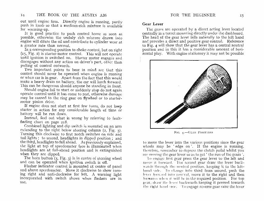
Gear LeverThe gears are operated by a direct-acti ng lever located
centrally in a turret mounting dir ectly un der the dashboard.The head of the gear lever falls naturally to the left handand provides a dire ct and positive gear control. Referenceto Fig. 4 will show that the gear lever has a central neutralposition and in this it has a considerable amount of horizontal play. With engine stationary it may not be possible
FIG. 4.-GEAR POS ITION S
to move the lever into th e various positions since th e gearwheels may be 'edge on '. If the engine is running,therefore. remember to depress the clutch pedal whilst youur« moving th e gear lever so as to get ' the run of the gears ' .
To e llgage first gear press th e gear lever to the left and111" \' 1' il forward . For second gear draw the lever back\1' ,11'1 1" 111 1'01 1/-:11111(: neutral position, keeping it to th e left IIl1l1d ~. i d (' , '1'" (' liang( : into third from second, push theh' \,('1 1' 11 1\':11.1 iulo nt-u l r. rl , move it to the right and then111 1Wil l .1'1 WIIl' II il will Iw ill the required position. For topll lJ' l l, d llllV II I., 1.,\,(,1' backwards keeping it pr essed towardsII II' I IMIII II:I III I sid." To cngage reve rse gear raise the lever

16 THE BOOK OF THE AUSTIN A3S FOR THE BEGINNER 17
Fro. 5.-BoNNET CATCH. I n set shows safety catch
by pullin g it upwards against the spring pressure, move itfully to the right and then rearwards. The resistance byspn ng pressure prevents its being engaged accidentally.
The handbrake lever is to the right of the driver's seatadjacent to his right hand. lt is of the pull-on type, thelever being pulled up and rearwards to apply the braketo the rear wheels. A ratchet locks the lever in the ' on 'position by. a tr.igger and a pawl. By squeezing this triggerthe pawl IS disengaged and the handbrake is released.Sometimes, and par ticularly if the brake has been appliedwith some force, it is necessary to take the weight off therear wheel brakes either by pressing the foot-b rake pedalor by drawing the handbrake slight ly harder on and thenclearing with the trigger.
There are two tips you may like to know. If you wantto apply the handbrake very securely , press down the foot brake ped al at the same time pulling the handbrake leveron. The leverage obtained on the foot -brake is rathergreater than that developed by the handbrake lever andthis method of applicat ion may be found helpful particularlvin cases where the car is left on a gradient. If the handbrake cannot readily be released, press down the footbrake pedal; this will be found of assistance in releasingthe pawl.
The doors of the A35, either the two- or four-door model,may be opened from either inside or outside. The passenger doors can be locked from the inside by raising theinside handles upwards beyond. the normal position. Thedriver 's door is locked from the outside with the ignitionkey. Wh en thus locked, and with handles of other doorsraised, no doors canbe opened. This position also locksautomatically the sliding front door windows, when theyare raised. Remember to shut all the windows sufficientlyto prevent anyone from inserting a stick to release one of theinside door handles and so gain entrance to the car.
lt is useful to make a note of the code number of theignition key so that you may be able to obtain a replacement without delay should the need arise. A duplicatekey can be obtained at any time through your dealer .
The luggage compartment boot has a lock that acceptsthe ignit ion key enabling you to leave your luggage in thecar when necessary.
There are several body fittings that will be found convenient and helpful. For instance, a visor fitted to theroof above the windscreen on the driver 's side , and capableof being read ily hinged down, reduces glare from. the ~un.lt can also be moved sideways within limits and IS spn ngloaded to provide the necessary degree of frict ion to retainit in the desired position.
Checking RadiatorsBefore taking the car on the road at least two checks
should be made. There must be sufficient water in theradiator and the engine-oil level must be ne~r the ' Fu~ ,mark on the dip-stick-not more than t m, below It .
1'111 11 it will not be necessary to attend to these. ' I' 'v ry t ime th e car is used but both .these points
til l b h k d periodically . Grasp and hin ge forward, . motif n the bonnet front. This releases the
l It an 1 allows the bonnet to be lifted slightly.I t b fully raised because it .is retained by a ~afety'h n b r leased by inserting the fing rs (FIg. 5)·

18 THE BOOK OF THE AUSTIN A35 FOR THE BEGINNER
The bonnet can be held open by using the strut clipp edto its underside and hinged downwards. There is a cupshaped depression in the top of the radiator into whichthe lower end of the stru t can be fitted.
The bonnet is locked in the closed position by pressing itfully downwards. If it is not so secured the safety catch
F I G. 6.-D I P- STI CK L OCATI ON . I nset sh ow s ' F ULL ' markat which oil level sh ould be m aintained
\J
will prevent it rising but it probably will vibrate and rattleuntil such time as it is pressed fully hom e.
The radiator filler cap is removed by turning it anticlockwise and pressing it fully downwards. Add wat er ifrequired, filling so that the level is just below the top of thefiller-plug threads when the engine is cold. Preferably,use rain water-this contains no harmful deposits-for insome areas tap water can tend to fur formation. Replace
the cap securely. You will notice that it is of the pressurized typ e, a det ail dealt with more fully in Chapter X .
Checking Engine OilThe engine-oil level can readily be checked by first re
moving the engine dip-sti ck fitted on the near SIde of theengine at the front. It is as well to have the car on levelground when checking the oil level otherwise a misleadingreading will result. After the dip-stick ha.s been I?ulle.dout , wipe the lower end and replace the st ick pushing l.thome. On again withdrawing it you will see that the 011
vel is indicated on the scale by the oil marking (Inset,ig. 6). If necessary, add sufficient oil to bring the amounto the full mark.
A point to note is that whilst the level should never beowed to fall unduly, do not add so much oil that the
11 mark is exceeded. Apart from causing over-oiling,is excess oil will be wasted .Do not be tempted to use inferior or unsuitable lubricat ing
for these not only contribute to difficult starting-ce the engine may become too stiff to turn-but theyn prove expensive in the long run because of the irior lubricating properties.
switching on the ignition the state of the petrol supplyonce be evident by the reading on the fuel gauge .
uld the car have been standing for any length of timeurettor float chamber may have become empty.
ump has a priming lever fitted to it, and with itn ily supply fuel to the float chamber without
ng h engine (see page II7). To prime the cart 1 ull the lever upwards several times. If it is felt
t Ir ly it may mean either that the float chamb ery full or that the diaphragm is held down by its
opl:)rn. ting cam. In the latter case, turn the engin e throughu i n with the st ar ting handle when the diaphragm
urn to the released position. Then operate thet1l'II11lng 1 v r again, ceasing to do so when it is felt to work
r thi: mans th at the carburettor float chamber isth rre t level.
th bonnet , making sure that the catch secures it ,ready t o drive away.

20 THE BOOK OF THE AUSTI N A3S FOR THE BEGINNER 2I
Starting the EngineAfter taking your seat see that the handbrake lever is
on, i.e. pull ed up, and that the gear lever is in the neutralposition-that is, whe.r~ it can ? e. e.asily moved sid~ways
through it s central position. Thi s IS I~port~nt as accId~nts
have been caused by failure to take this routme precaution ,When starting from cold, particularly during frosty
weather, it is helpful to turn the engine by the startinghandle a few tim es before switching on. This relieves itsinitial st iffness and greatly reduces the load both on thestarter motor and- much more important- on the battery .It is also good practice to press down the clutch pedal forthi s again reduces the load and eliminates the drag of theoil on the gear wheels. .
If the engine is cold. pull out the choke contro l. Thisis held frictionally in any intermediate position if turn ed.Pull the starte r knob and the engine should soon commenceto run. Directly it does so, release the starter control.If the engine 'cuts out ' and stops do not again use thecontro l until the engine is at rest otherwise the drive ofboth starter and flywheel may be damaged. .
When the engine is running, gra~u~lly release the chok~,
resisting the t emptat ion to .keep It m use l?nger. than ISnecessary under the impression that the engme will warmup more quickly if this is done. It is better practice todrive away slowly since the engine will then warm "?-p,allowing the choke to be fully released s?on~r . ~y adoptI~gthis procedure not only will the lubricat ing OJI reta.m ItSproperties longer, because it will not tend to become dilutedby excess pet rol, but petrol will not be wasted.
Starting When WarmOnce the engine is warmed up it is not norm ally neces
sary to use the choke and, of course, the accelera tor mustbe left in the normal idling posit ion. If it is pressed down,so opening the throttle, not only will the idlin g jet berendered inop erative- since it relies for its action on thesuction set up by the virtually closed throttle-but theaccelerating pump may inject petro~ into the manifold ?-ndcause difficult starting should the mixture become too nch.
This matter is covered more fully when we deal with theCarburettor (Chapt er VIII).
If the engine has cooled down a little it may be foundadvisable t o use the choke momentarily. If so, beware ofhaving the mixture t oo rich for then the l?lugsmay be shor~
circuited with petrol and no spark will occur. If ~hIS
happens, push in the choke control fully at the s~me timepressing down the accelerator so that as the engme turnsthe unduly rich mixture will be cleared. As soon as theengine commences t o fire, gradually :elease the choke whenit is felt t o pick up speed and agam run normally.
If the engine still refuses to start ren::ove the plugs forcleaning. The simplest method of treatmg sparkmg plugsthat have become wetted with petrol as the result of ' overchoki ng ' the engine is to place them on th~ ground withtheir 'business-ends' t ogether, apply a lighted matchand allow the petrol to burn off. If you have that mostuseful accessory a 'file-card', brus h them up with th!s ;otherwise wipe away the soot with a rag. Before replacmgthem in the engine make sure that the gap between thepoints is not bridged with carbon or fluff. fron:: the .rag.
The golden rule is to use the choke WIth discreti on,
Driving HintsBefore you can take the car on to the road you must
obtain a provisional driving licence so that you may betaught to drive by an experienced friend or by one of themany motoring schools instructors. Until you have pas~ed
the official driving t est you must always be accompamedby a drive r who holds a current driving licence. It is mostdesirab le to take your lessons with some competent driveramong your acquaintances or at a school with a goodreputation. Eve n so, the following instructions may wellbe set down and borne in mind :
To start from rest, first press down the clutch ped al andmove the gear lever to the bottom-gear position by pressingit fully towards the left and then forwards. You may findthat the lever will not readily enter the bottom-gear position.If this occurs, return it to neutral, momentarily engage theclutch, declutch and again move the gear lever to thebottom-gear position when it should fully engage. This

22 THE BOOK OF THE AUSTIN A3S FOR THE BEGIN NER 23
difficulty sometimes arises due to the fact that the slidinggear teeth are 'edge on' to each other and thus cannotmesh . Allowing the clutch pedal to engage momentarilyalters their relative positions and so permits them toengage.
Now release the handbrake lever, first pulling it upwards slightly to ease the pressure, squeeze the trigger tofree the ratchet and push the lever forwards and downwards.If it is difficult to release the holding ratchet , press firmlyon the foot-brake pedal to relieve the t ension on the hand-brake linkage. .
Press down the accelerator slightly at the same timeallowing the clutch pedal to come gently up and the car willmove forward as the clutch engages. The first point tonote is that the simultaneous actuat ion-one up and onedown-of the clutch and accelerator pedals is not easyand possibly un even clut ch engagement may ensue. Persevere, however, for it is only mastered by experience.Bear in mind that the hall-mark of a good driver is smoothclutch engagement and that harsh clut ch engagement isharmful for it causes severe mechanical stress.
Gear ChangingWhen the car is moving forward steadily it will be neces
sary to change into second gear. One of the main bugbears of the novice-gear changing- is almost entirelyeliminat ed by the synchromesh device.
To change from first to second gear, allow the acceleratorto return to its closed position at the same time pushing 'down the clutch pedal as far as it will go. Then, withoutundue haste, move the gear lever rearwards maintaining 'a steady pressure on the lever. A slight resistance maybe felt but maintain the pressure on the knob. When thesynchromesh device has come into action the gears willmesh and second gear will be engaged noiselessly. Allowthe clutch pedal to return gent ly. At the same time pr essdown the accelerator when the car will move forward withincreased speed.
To change from second to third similarly release theaccelera tor and depress the clutch pedal. Move the gearlever delibera tely forward into the neutral position main-
taining a pressure to the right through the gate and thenforward into third speed. Allow the clutch pedal to returnand control th e speed of the car by the accelerator pedal.
The final cha nge into top gear is effected by releasing theaccelerator pedal, depressing the clutch pedal, and movingthe gear lever rear wards into top-gear position, maintaininga pressur e on the lever tow ards the right-hand side.
Practise gear changing in this manner until the car movesforward smoothly and steadily after each gear change.Carefully synchronize pedal movement t o ensure smoothengagement in all circumstances.
To Change Down to a Lower GearIt is equally necessary to learn how to change down
from a higher to a lower gear. This is essential wh~n
climbing a hill that normally the car could not ascend III
top gear or whicheve r other gear may be in use at thetime. Also, traffic conditions may necessitate t ravellingmore slowly than normally is permitted by top or third gear.
In cha nging down from top to third gear and from thirdto second adop t the following procedure . Maintain thepressure on the accelera tor and de-clutch. Simultaneously,push the gear lever steadily into the desired position. Thesynchromesh device again comes into action to give a silentchange. Release the clutch pedal, controlling the speed ofth e car by using the accelera tor pedal as necessary.
A slightly different procedure should be adopted whencha nging down from second to bottom as in this case thereis no synchromesh device. An easy cha nge can be made,however, by adopting the technique known as ' doublede-clutching ' . Although this procedure may appear tobe complicated it is simple and you should practise untilyou are proficient.
Proceed as follows:
(a) De-clut ch. Move the gear lever into neutral , releasingthe pressure on the accelerat or.
(b) Allow clutch to engage, with gear lever in neutral,and accelerate the engine.
(c) Release pressure on accelerator pedal, de-clutch andmove gear lever into first-gear position at once.

THE BOOK OF THE AUSTIN A3S FOR THE BEGINNER 25(d) Engage clutch, operate accelerator to maintain desired~~. .
Practi se this drill until you can be sure of making acertain an d rapid gear change in any circumstances,particularly when ascending hills on which bottom gearcould have been used.
To stop the car , first of all t ake your foot off the accelerator and move it over to the foot-brake t o the left.Just before the vehicle comes to a standstill depress thedutch. When stopped apply the handbrake, move thegear into neutral and then release the clutch and footbrake,
ReversingWhen engaging reverse gear the car must always be
stationary . Any attempt to go into reverse when the caris moving forwards will cause severe strain or damage tothe transmission system.
With' the car stationary and the engine running, de'd utch and lift the gear lever upwards until you feel itwill rise no further. Then move it through the gate t othe right maintaining the lift. Next, pull it rearwardsinto the reverse position. If it does not engage fully, moveit forwards mom entarily allowing the clutch pedal toreturn as when engaging first gear. De-clutch once moreand again move the lever backwards. Engage the clutcha nd gently accelera te when the car will move backward s.
Almost the first thing you will realize, of course, is thatthe steering is now reversed. That is t o say, turning thesteering wheel to the right causes the front of the cart emporarily the rear-to move to the left . You will soonbecome familiar with these changed conditions,however, andlearn how to back your car neatly into the desired position .
It is a helpful idea to erect two guide marks and then to:practise reversing between them- for instance, as if back In into a line of parked vehicles. Nothing indicates thenovi so much as inabi lity to back his car neatly intopia. not forget to allow for the swing of the frontmudguard and bumper when pulling out from behind acar that is ah ad of you. A little pract ice will very soonshow you how much room you may allow.
SkiddingThe brakes on your Austin A35 are powerful and
efficient but it is bad driving technique to use them harshlyexcept, of course, in emergency. Harsh braking reducestyre life as well as st ra ining the car generally.
Every novice fears a skid. Whilst it is easy to say• never provoke a skid' you may be compelled, becauseof some other person 's stupidity, to jam on your brakeswhen the surface is wet. Then you may experience theunpleasant feeling that the car is not entirely un der yourcont rol. It slides forward and not necessarily radiatorfirst ! If you have time to make a split-second decision,immediately release the brakes. Then carefully re-applythem avoiding any tendency to lock the wheels. Oftenthis factor is the cause of a skid.
What generally happens is that the rear wheels swingsideways towards the gutter or to the lower side of theroad. Often the skid will become controllable if you turnthe steering wheel in the same direction as that to whichthe skid develops. If you turn the wheel in the otherdirection you may finish up across the road!
Do not forget that knowing what to do in an emergencymay be of great value. If you are able to practise skidcont rol in an isolated place you will realize the reason whybus drivers and drivers of police cars use a ' grease-patch'to t each them the correct t echnique.
Try to bear in mind the following four points:
(I) Steer a steady course. Never swerve abruptly.(2) Do not accelerate nor apply the brakes suddenly or
harshly.(3) Do not drive on the crown of the road, particularly
if your road speed is low. Keep well to the left.(4) Do not allow the engine to labour. If the speed
falls so that the engine runs heavily, pinks, or appearsto vibrate unduly, change down to a lower gear.
Running-in a Reconditioned EngineWhen the engine has done considerable service it may
become beyond further repair-in that case a reconditioned

Endeavour to become accustomed to the sound that theengine makes at these running-in speeds. It is not necessary to drive at any particular running-in speed but allowt he engine t o run easily within the ranges tabulated. If theengine feels stiff, stop for a t ime to allow it to ' ease off ' .All the working parts are assembled somewhat on the tightside and care in the early stages will enable them to bedin sat isfactorily .
/ I.S th e engine becom es run-in you will quickly sense theadd ed power and response.
Some owners like to use a running-in compound. Thereare severa l on the market, any one of which may be usedprov ided it is theproduct of a mak er of repute and that
26 THE BOOK OF THE AUSTIN A3S
engine may be obtain ed from the Aust in Motor Co. Ltd.Consult your 'Aust in agent who will arrange the matter foryou. An allowance may be made for your old engine.
For the first 500 miles-or, if your can manage it , forthe first 1,000 miles- handle the new engine wit h care . Ifit is carefully run-in your consideratio n and t rouble will berepaid by smooth and efficient performance for a long timeafterwards .
When starting from cold , do not 'rev-up ' the engine .Release the choke control as soon as possible. Whendriving away avoid rapid acceleration .
The engine is produced within extremely fine limits inso far as the bearing surfaces are concerned. In orde r toallow the working par t s to become run in and to attaintha t surface hardness that ensures long life, high enginerevo lutions and excessive speeds should be restrict ed duringthe early stages. Do not be in a hurry to see how fastyour car can travel nor to maintain high road speeds un tilthe ru nning-in period has been completed. The followingare the suggested maximum speeds in the various gearsduring the running-in period, changing down as road conditions dictate :
Bottom gear:SecondThirdTop
7 miles per hour152540
FO R TH E BEGINNER 27
the proportions used are as advised . Some of th ese graphitecompo unds may t end to become separa ted out in filter sof the full-flow type. If that occurs it may be founddesirable to fit a new element when the oil is changed afterthe first 500 miles.
General Check at 500 milesWhen the reconditioned engine has run for some 500
miles, t he engine oil should be drained and the sumpreplenished with new oil of the correct grade and of anapproved brand. If it is necessary to flush out the sumpdo not do it with paraffin but use a suitabl e flushing oilinst ead.
At the same t ime the cylinder-head nuts should be testedand tightened in the order shown in Fig. 32. After thisinitial tightening, th e cylinder head shou ld not require anyfurther a t tention.
The thin stee l cylinder-head gasket used on the A35will not compress to the same degree as a gasket of thecopper-asbestos type. Nevertheless, it is advisable tocheck th e overhead- valve rocker clearance afte r tighteningth e cylinder-head nuts (see page 96).
Check also that th e sparking plug gaps are '025 in .(,64 mm.) (see page 179, and F ig. 72).
Th e contac t -break er gap should be checked and set a tfrom 0'014 to 0'016 in. and t he ind ex scale might usefullybe re-set at this stage (see page 174).
Now th at th e engine is running more freely, the carburettor adjustm ent should be checked and re-set if necessary.Fullinstructions are given on page 109.
A check on nu ts arid bolts is worth while to make surethat the reconditioned engine has bedded-down and thatit is secure in it s mountings after the init ial 500 milesrunning.
Choice of PetrolThe choice of particular brand of pet rol is a matter for
your individual decision as also is that of the grade-adifferent matter from brand.
The particular grade of fuel used will affect engine performance. In genera l, altering the ignition advance is all

28 THE BOOK OF THE AUSTIN A3S
that is required to obtain the maximum benefits from thedifferent grades of fuel available. For the higher octanefuels, however, full advantage can only be obtained byincreasing the compression ratio, a procedure that is notgenerally worth while at present due to the limited distribution of this special grade of petrol. The method ofroad testing the car to obtain the most efficient ignitionsetting, is described on page 177.
At the time of writing, there are two main grades generally available. These are 'Regular' and ' Premium'.
Regular is somewhat similar to war-time 'Pool'.Premium corresponds roughly to No. I petrol availablebefore the War.
Premium grades contain some additives that confer properties giving improved performance.
In addition, in determining which grade to use, theremust also be taken into consideration the matter of compression ratio, and whether this ration has been lowered orincreased by the introduction of a different gasket to theone originally fitted.
When it cleared the Works, your reconditioned enginewas adjusted to accept Regular fuel. With this originalignition setting, Premium fuel may not give the fullestbenefit. This advantage may be obtained only if theignition is set to suit this grade of petrol. Usually theignit ion must be advanced (see page 177).
Conversely, an engine with ignition timed to operate withPremium fuel will not give a good performance if theRegular grade is used. Again, the-ignition should be ad-justed to suit it . '
CHAPTER III
GENERAL MAINTENANCE
Body, Wheels and Tyres
T HOSE MOTORISTS who are of the opinion that achassis is a metal frame the purpose of which is to
support the body may wonder what maintenance such achassis can require. Actually, the term chassis embracesthe wheels, axles, springs, steering connect ions, ty res, etc.These components do not require a great amount of attention but care in keeping nuts and bolts t ight and all partsproperly lubricated will do much to remove the squeaksand rattles that are not only annoying but advertise tothe world the owner 's neglect .
Keeping Nuts and Bolts TightManufacturers today use torque spanners to enable a
definite degree of tightness to be obtained. As cork orrubber gaskets are used in many parts it is very desirableto control tightness of nu ts securing these parts. Correcttension is achieved by pre-set loadings rather than byindividual assessments of what' seems to be tight enough '.
It is advisable to periodically examine all nuts for ti ghtness. If neglected they will become rapidly looser andrattles, squeaks and accelera ted wear will result. Somebolts are secured by t ab washers, some by cotter pins. Ifthere is evidence that such bolts are not correctly tightenedremove the pin or bend back the tab washer as requiredand re-tighten. Do not forget to secure them when theyhave been tightened . Cotter (or sometimes called split)pins and tab-washers are two means of preventing nutsfrom becoming loose.
A cotter pin passed through a hole in the end of a nutor stud passes through the slots in a castellated nut . Whenso positioned the ends of the split pin are bent back thusmaking it impossible to withdraw the pin and preventingany slackening of the nut itself.
29
30 THE BOOK OF THE AUSTIN A3S
Removing Nuts and BoltsIt oft en becomes necessary to unscrew nu ts and bolts
th at have rusted. Some bolt s-for instance, in the bodyscrew into nuts th at are inaccessible so preventing a secondspanner bein !5 placed on t~em to stop them from turning.If the enthusiastic owner tnes to unscrew these it is possibleth at the nut , having firmly ru st ed, will refuse to unscrew.
If th ere is any dou bt about it, brush the mud off th ebolt threads and apply paraffin or penetrating oil, allowingreasonable time for this to do its work.
Always use a set-spanner or box-spanner whereverpossible. An adjustable spanner , even of the best t ype,usually springs a little an d is apt to damage the sides ofthe nut.
A split pin can often prove surprisingly difficult to remove.A useful tool for th e ~urpose is an old screwdriver carefullyground down to a pomted prong. This can be inserted inth e head of th e pin, enabling it to be levered out once afirm grip is obtained. If the pin cannot be extracted holdthe bolt head with one spanner and, using another set spanner on the nut, shear off th e pin . This practice israther one of despair for the threads of the bolt and of thenut can be damaged by this proced ure. After the nu thas been unscrewed, assuming that the threads are in goodorder , punch out the pin that st iJl remains in the drill edhole of the bolt.
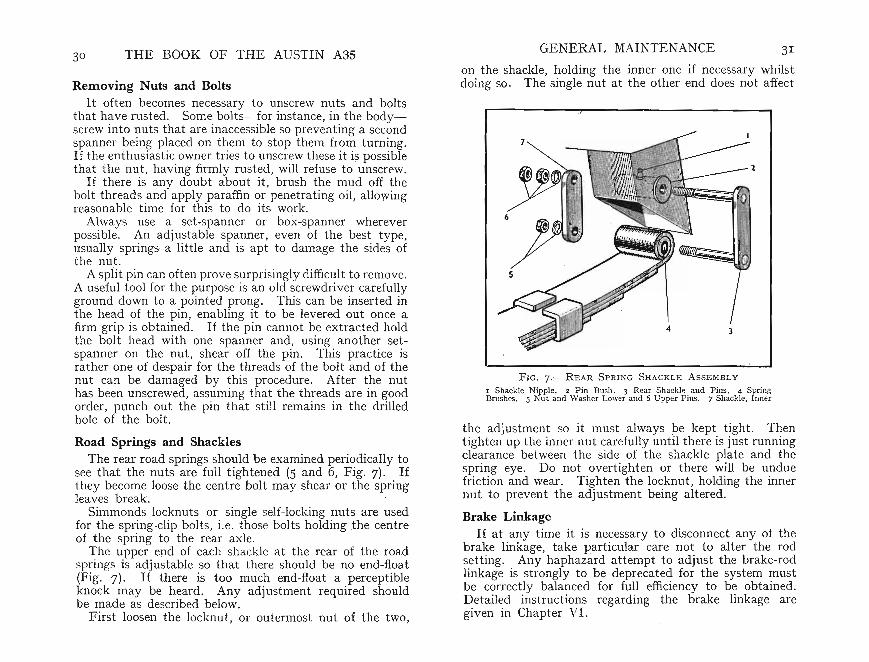
Road Springs and ShacklesThe rear road springs should be examined periodically to
see that the nuts are full tightened (5 and 6, Fig. 7). Ifthey become loose the centre bolt may shear or the springleaves break. .
Simmonds locknuts or single self-locking nuts are usedfor the spring-clip bolts, i.e. those bolts holding the centreof the spring to the rear axle.
The upper end of each shackle at th e rear of the roadprin gs is adj ustable so that there should be no end-float
(Fig. 7). If there is too much end-float a perceptibleknock may be heard. Any adjustment required shouldbe made as described below.
First loosen the locknut , or outermost nut of the two,
GENERAL MAINTENANCE 3I
on the shackle, holding the inner one if necessary whilstdoing so. The single nut at the other end does not affect
FIG. 7. -RE AR S P RING SHACKLE ASSEMBL Y
I Shackle Nipple. 2 Pi n Bush . 3 Rea r Shackle and Pins. 4 SpringBrushes . 5 Nu t and Washe r Lower and 6 Up per P ins. 7 Shackle, Inner
t he adjustment so it must always be kept tight. Thentighten up th e inn er nut carefully until there is just runningclearance between the side of the shackle plate and thespring eye . Do not overtighten or there will be unduefriction and wear. Tighten the lockn ut, holding the innernut to prev ent the ad justment being altered.
Brake LinkageIf at any time it is necessary to disconnect any of the
brake linkage, take particular care not to alter the rodsetting. Any haphazard attempt to adjust the brake-rodlinkage is strongly to be deprecated for the system mustbe correct ly balanced for full efficiency to be obtained.Detailed instructions regarding the brake linkage aregiven in Chapter VI.

32 THE BOOK OF THE AUSTIN A3S
Steering GearThe alignment of the front wheels is an extremely impor
tant point . Whilst the rear wheels are definitely fixed,the front wheels are not . If there is any incorrect adjustment at the steering linkage not only can undue tyre wearoccur but the steering can be affected.
The steering connections are of the adjustable type andwith proper lubrication will give long service, but if thecar has bumped into a curb, for inst ance, one of thesteering arms may have become bent .
The standard setting of the front wheels is tha t theyshall point togeth er slightly to the front. In other words,the dist ance at hub height measured between th e wheels is* to t in. less than the corresponding dimension at the rearedge. Th e reason for this is that in use th e wheels tend toseparate slightly to take up th is initial' toe-in' and so run inth e most efficient position. If you wish to check the ' toe-in'refer to page 57, where this adjustment is described.
The steering linkage and front suspension are veryimportant points and if you feel that there is some partstrained or bent it is best to let your Austin dealer inspectth e parts to make sure every thing is in order.
Grease, Oil and LubricantsThe chapter on lubrication (see page 193) describes the
various parts to be greased or oiled. It is not sufficientto place the oil gun on a lubricator, press it several tim esand assume the job is well done. The lubricator itselfmay have been damaged (possibly it may have beeri hit.accidentally with a spanner), or the passage may havebecome choked. In either case the lubricant will not enterwhen the grease gun is applied to it. When lubricatingthe chassis, th erefore, it is always good practice to continueuntil the lubricant can be seen escaping from the bearingthat is receiving attention. Th is does not apply to lubri-
u l rs on, for inst ance, the wheels, where excess lubricantcan r h the brake linings.
Oil and gr ase not only lubricate but also form a sealthat prevents water and grit from entering the bearing andcausing it to wear much more rapidly than would be thecase if it were adequately lubricated.
GENERAL MAINTENANCE 33
Hence the importance of operating the gun several timesif necessary so that the old lubricant, carrying with it anygrit or water , is forced out and clean grease takes its placeon -the bearin g surfaces .
If a lubricator has been damaged, it is cheaper to replaceit than to leave it in place for this can only result in thebearing runmng dry and wearing out mu ch earlier th an itshould. The bearing thus damaged can cost many t imesthe small charge for the lubricator. Assuming that youcannot force any thing through the lubricator, it is advisable to replace it with a new one. If the lubricator isfree, however, it can only mean that the bearin g itself hasbecome choked and it will be necessary to dismantle itfor cleaning. Certain grades of cheap lubricant are liableto hard en in use and choke the passages. Always buy agood lubricant of correct grade and type marketed by amanufacturer of repute.
Keep the bottom of the engine clean, particularly thesump. A coating of mud prevents air acting on the wallsof the sump to keep the oil cool. Paraffin and a st iff paintbrush will be found most convenient for this.
Care of the BodyworkAlthough the modern body finish will stand much rougher
use than the varnish finish of earlier cars , there are certainways in which the owner even with the best intentions canmar it" lustre.
Do not be tempted to dust the car down without usingwater. Road dust is an abrasive and unless Iiberalquantities of water are used to float this dust off thesurfa~e the cloth, acting on the dust, will produce myriadsof mmute scra tches. In a short time the finish will havebeen considerably dulled.
The first rule, then, is to wash the car , using preferablya hose and running water in conjunction with a sponge orsoft cloth. An important point is to keep the hose itselfclear of the body. Inevitably it collects grit and whenaccidentally pressed against the body or wings can causedeep scratches.
Dry the car with a chamois leather and then polish . Donot be tempted to overdo the polish. Too frequent anapplication, particularly in the case of wax polishes, can
34 THE BOOK OF THE AUSTIN A3S
actually dull the surface. Properly applied, a film ofpolish protects the body and gives a good gloss. On theother hand, a thick coat is not twice as good as one thinone, for it cannot be adequa tely polished and must tendto attract dust so dullin g the lustre. The best method isto apply the polish sparingly, rubbing it on evenly andth en polishing it vigorously.
The windscreen and windows should be cleaned with washleather. Do not omit the rear window because clear visionfrom the rear is essential.
Wh en washing the car a minor point to note is to avoidwater on the brake plates and drum s. Althou gh it willnot do any permanent harm, it will reduce imm edia tebraking efficiency. When taking the c~r ~m t he road ~or
the first time after it has been washed It IS good practiceto test the brakes and gauge their performance. If it isobvious that water has reached the shoes, apply themsevera l t imes whilst the car is in use. This will have theeffect of warming the drums and evaporating the moisture.
Many owners, particularly those living near the se~,
give the car an occasional wax treatment as a further aidin protecting and maintai~ing t he finish .. Some apply wa,xbut using a portable electnc tool as supplied for handyman s, do it yourse lf ' t asks. To get best resul~s work on a daywhen it is not very hot so tha t solvent m wax does notevaporate too quickly. On the other hand, a humid dayis unsuit able, a solvent will evaporate too slowly . .
Method of application is imp ortant. Take up a Iittlewax on a pad of mutton-cloth slightly damped with coldwater. Apply evenly over a small area, say, for instance,half a door panel. When wax has been spread, polishimmediately by fast strokes with a clean linen rag ormu t ton-cloth. Carryon in this way until all body surfacehas been covered. Experience alone will t ell you how muchpolish to use and how large an area can be done at a time.Rememb er to include interior mouldings and also thatwax polish may be used to brighten rubber moul dingsaround windows and windscreen .
Removing TarSummer usually brings tar- sprayers into action, and you
will be lucky if you can avoid collecting at least a few spots
GEN ERAL MAINTENANCE 35
on your car. They can usually be removed, however, bydipping a soft cloth in linseed oil and rubbing gently. Ifpossible, t ackle the job before t ar has t ime t o set. If spotsare really obsti na te, try a mixture of two parts petrol toone of engine oil. With cloth around one finger moist en itin solution and rub spots. Avoid applying this cleaningagent to any other parts of car . I mmediately t ar spothas been removed, wash away all t races of petrol and oilmixture and re-polish.
Touching-up EnamelIt is inevita ble th at th e synthetic-enamelled parts of
the car will be scratched or possibly damaged by flyingsto nes. If neglected , rust will attack the bare metalsurfaces and gradually cause th e surrounding enamel toflake off. Th e careful owner will find it most ad vantageousto tou ch up such bare places as soon as prac ticab le. . Notonly will the appearance of the car be preserved, but It WIlldepreciate far less rapidly. Do not touch up a surfaceth at has already rust ed but carefully rub it down withvery fine glass paper until the bare metal is bright beforeapplying the enamel. Use quick-drying synthetic enamelfor th e purpose and not one of th e cellulose type. Theselatter have a differen t weathering rate, and even if thecolour match is good at first it may soon change its t intconsiderably and call attent ion to th e minor blemish it"vas desired to conceal.
Care of the InteriorIt is important to keep the interior of the body free from
dust or road grit . To prevent road grit from being carriedinside the car is impo ssible, but once it is there it is troddeninto th e carpet and damages the fibres. A vacuum cleaner,if available, is the most convenient way of cleaning theinterior. It may also be used to keep the upholst ery clean .
Seat covers are a worth-while investment for they tendto keep the original upholstery in good condition . Whenthe time comes to sell the car, a clean and attractive appearance is a good sales feature so far as the upholsteryis concerned .
Leather upholst ery may be cleaned by using a dampcloth having a little soap on it and applied briskly to the

THE BOOK OF THE AUSTI N A3S GENERAL MAINTENANCE 37leather. The soap film should be rubbed off with anotherdamp cloth . The upholstery can be finished by polishingwith a soft , dry cloth.
Do not be tempted to use an unsuitable polish on leatherupholstery for this sometimes makes it tacky and yourpassengers, particularly your lady passengers, will notappreciate the sensation of sticking to the seats or havingtheir costumes marked!
If desired, a good quality furniture cream may be rubbedon the leather when it is thoroughly dry.
Cloth upholstery can be cleaned with one of the carbontetrachloride liquid cleaners. But, the best advice is toavoid getting it dirty in the first place !
Doors, Locks and HingesThe work ing parts of the door-lock striker plate and
lock should be lightly lubricated- not only to cause thepart s to work smoothly but also t o eliminate undue wear.It is advisable to examine and tighten periodically, if
. necessary, the various screws securing the door locks,striker plates and hinges.
Sometimes it may be necessary to remove the interiorhandles but, if so, their method of attachment is not alwaysobvious. By adopting the following procedure no difficultyshould be experienced.
First, push the chrome-plat ed washer, or escutcheon,away from the handle as far as possible. Then a pin willbe seen in the handle shank and this can readily be pushedout of the shank when the handle may be pulled off theshaft.
To refit the handle first make sure that the handle is onthe square that has a drilled hole to align with the one inthe handle. Check to make sure that the handle positionis the one that is most convenient. Replace the handlehalf a turn out when it may be found more suitable.
Check the seat slides for free movement. Usually afilm of oil on the working par ts will assist the slide towork freely. Nothing is more annoying than to strugglewith a sliding seat that will not slide- or, alternatively,will slide and not lock. Avoid applying excessive lubricantto the slides for this may come in contact with clothingand leave marks.
Protection During StorageBefore placing car in storage it is advisable to protect
cellulose finish and plated parts by applying a heavy filmof wax and leaving it without polishing. When car is to beused again, remove this wax coating by cleaning withliquid car polish and following up with a normal waxt reatment.
Carpets should be protected with an anti-moth preparati on aft er interior has been tho roughly brushed out.
Batteries should be sent to your local Austin dealer orLucas Service Station for maintenance during the time caris laid up (see page 168).
TYRES
Tyres elimina te high-frequency vibrat ions and minimizeshocks due to inequalities in road surfaces. They functionbecause amount of tread in contact with road covers acomparatively small area. Not only must tyres be flexiblebut also strong enough to contain air under pressure, toughenough to resist damage, giving long mileage, and be ableto transmit driving and braking forces satisfact orily.Further, they must provide road grip, st abilit y and goodsteering properties. To this somewhat formidable list ofrequirements tyre manufacturers have nobly responded,and tyres today seldom trouble us.
Modern tyres have a strong casing built up of severalplies of cord fabric- or, more recently , of rayon or evensteel wire-forming a tough wall and t read. They aresecured to wheel rim position by wire bead cores.
Part of the work done by deflection of tyres on a movingcar is converted into heat within them. This is easilydemonstrated if you place your hand on a tyre after a fastrun. You will find it quite warm, sometimes excessivelyso. Both rubb er an d fabric are indifferent conductors ofheat, and internal heat is not easily dissipat ed. Suchtemperatures weaken tyre structure and reduce treadresistance to general wear.
Importance of Correct Tyre PressureTyres are designed for use under pre-determined condi
tions, and tables are available to show pressures to be used

Tubeless TyresTubeless tyres are fitted as standard equipment to allAustin
A35 models. They have many advantages over the conventional type in which a tube under t ension is stretched byinternal air pressure . If punctured, say by a nail, the hole
t read and causes considerable friction and excessivet emperature within casing (Fig. 8).
On the other hand, over-inflation causes wheel bounce,resulting in discomfort to occupants of car. It also resultsin excessive wear, especially in rear wheels, for they spinimmediat ely they lift in the air. When they touch groundagain their speed is suddenly reduced by contact with roadsurface and in that brief inst ant their tread is abraded.This cycle of events is continually repeated, for no roadsur face is quite smooth nor is any shock-absorber syst emperfect . Excessive pressure also redu ces comfort andt read life, for there is a concentra tion of load and wear ona smaller area of tread . On front wheels it contributes towheel wobb le. Particularly is this the case if there is somewear at stee ring connections or swivel axles, or if there islocal wear in the form of a narrow band around the circumference at centre of tread.
Even when in good condition, pressure is lost due tochemical diffusion of compressed air through walls of theinner tube. Rate of loss is from I to 3 lb .ysq. in. per week ,or about 10 per cent. of the original pressure. Therefore,it is advisable to check all tyr es once a week and maintainpressures at recommended figures. Do not anticipateleaking by over-inflating, nor reduce pressure that hasincreased owing to a rise in temperatures- for example, ason a hot day-for it will be reduced to normal with the coolof evening.
It will be seen tha t variations in tyre pressure, either upor down, result in reduc ed tyre life. A few moments spenteach week in checking pressures and correcting them ifnecessary is t ime well spent.
Although the spare wheel is a real help in time of trouble,many an owner has found to his discomfort that whenrequired it is flat, or it s pressure is below normal. Do notforget, therefore, to check its pressure also as part of normalroutine.
38 THE BOOK OF THE AUSTIN A3S
under different loads and deflections. It is important toensure that tyres are always maintained at pressuresrecommended by their makers, for these are the result ofconsiderable laboratory work and practical t ests. Recommen ded pressure for the A35 is 20 lb. per sq. in . bothfront and rear , giving a suitable distribu tion of load to thatpart of tyre in contact with road surface. This is for twopersons. With a full load the pressure o~ the rear tyresshould be increased to 23 lb. per sq . Ill . Tyre size :5'20- 13.
Do not attemp t to judge pressure merely by appearance.Check with pressure gauge, obtainab le from your dealerwho will inflate your tyres to correct pressure on request .Check by app lying gauge directly to va lve when tyres arecold and not when they have attained running tempera ture.Appearance of a tyre may be normal, desJ?it~ t he fa~t thatgauge shows it t o be nn der-inflated . ThIS IS sufficient tocause abnormal tread wear.
Some owners consider that a slightly reduced tyre pressure gives more comfortable r iding. Even if this wereso there are distinct drawbacks in having tyre pressurestoo low. One is that tyre will be damaged internallysince plies- due to excessive flexing- deteriora te muchsooner than normally. Consequent ly there may not bethat exact control as is the case when tyre pressures areheld at recommended figures. Under-inflation causesun necessary tyre wear-on an average 13 per cent. forevery 10 per cent. reducti 0J.! in p~essure belo:-v recommended figure. This results .m unmist akable evidence on
FIG. S .-EX CESSI VE W E AR CAUSED BY UNDER I N FLATION
GENE RAL MAINTENANCE 39

40 THE BOOK OF THE AUSTIN A3S
immediately enlarges and the tyre often deflates suddenly.With a tubeless tyre, however, the nail is usually retainedin the cover , in which case any escape of air will be so slowthat a journey-even of a hundred miles or so-maybe completed without wheel-change. Tubeless tyres incorporatea special interior liner as an integral part of the tyre givingprotection against rapid air loss when the tyre is punctured(Fig. 9).
Tubeless tyres give a high mileage because they generatelittle heat and are extremely flexible. Excessive wear
c
FIG. g .-SECTION OF T U BELE SS T Y RE
A Air Retaining Liner. B Air Seal. C Sealed Valve
caused by under- or over-inflat ion is eliminated becausethey keep their correct pressure for a longer period.
If a tubeless tyre is damaged so that it becomes deflated,the wheel can be changed in the normal manner, but thechance of this happening is much less remote than with theconventional tyre and tube . For an emergency repair aninner tube may be fitted.
An air-tight seal between wheel and tyre is achieved byaccurate forming of bead bases to suit contour of wheelrims . In addition some tyres have sealing ribs formed inside of beads that contact side of rim. On tyres notprovided with sealing ribs, the beads have very smoothand carefully formed sur faces to provide an efficient seal.
GENERAL MAINTENANCE 41
Procedure for removing and installing tubeless tyres issimilar to that for conventional tube and tyre assemblies,but the following details should be carefully observed.Before inst alling a tyre ensur e that rim is clean and freefrom rust or damage. Do not use a hammer or tyre leverto free tyre beads from rim, but do so by 'treading 'around tyre with the feet, keeping clear of beads. Wheneasing beads over rim take care that they are not damagedby t yre levers.
When inflating a t yre immediat ely after fitt ing, proceedas follows: (a) Before installing valve core, inj ect a fewquick shots of air into tyre to force beads on to bead seats .(b) Inst all valve core and inflate tyre to 40 lb. per sq . in.Check for air leaks by submerging wheel and tyre assemblyin water. After ensur ing that there are no air leaks at baseof valve or valve core, wheel rivets or bead seats, deflate torecommended pressure , e.g. 20 lb. per sq. in . (two persons) .
If difficulty is experienced in seating beads they must bespread by constricting centre of tread. This can beachieved with a tyre constrictor t ool, or alt ernatively apiece of rop e can be used around t read and tightened witha tyre lever in the manner of a t ourniquet .
To assist in prevent ion of punctures, tyres should beinspected regularly so that any objects likely to causepunctures may be removed.
Repair MethodsRepair of tubeless tyrcs, though rather different from that
of the conventional inner tubes, does not present anyserious problem. There are several repair kits on themarket with full instructions.
Punctures of the type normally caused by small nails orsimilar objects can usually be repaired without removingtyre from wheel. Two methods of effecting this type ofrepair are the ' Sealing Gun Method ' and the 'PlugMethod '.
When dealing with punctures having an irregular-shapedcut, it is necessary to remove tyre from wheel and repairby methods mentioned below. It is suggested, however ,that you consult your Austin dealer or t yre service depot.
SEALING GUN METHOD. Thi s type of repair is suitableonly for sealing small nail-holes. After reducing inflat ion
D
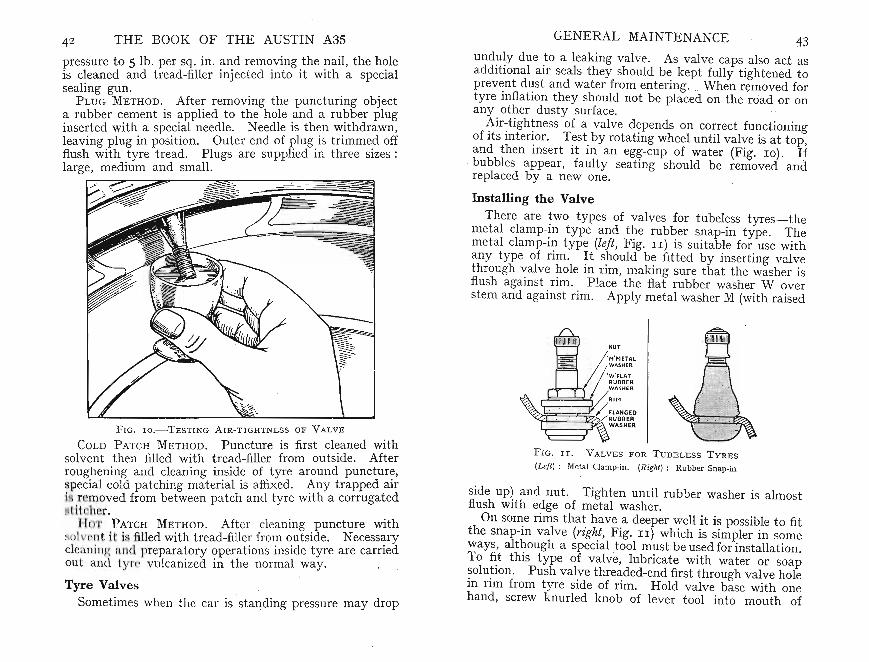
side up) and nut . Tighten until rubber washer is almostflush with edge of metal washer.
On some rims that have a deeper well it is possible to fitthe snap-in va lve (right, Fig. II) which is simpler in someways, although a special tool must be used for installation.To fit this type of va lve, lubricate with water or soapsolution. Push valve threaded-end first through valve holein rim from tyre side of rim . Hold valve base with onehand, screw knurled knob of lever tool into mouth of
43GENERAL MAINTENANCE
NUT
'M'METAl
~':~SlHAE;RUBBERWASHE R
~~~~§~RIM/ FLANGEORUBBER
~~~r~WA SNER
FIG . lI.- V ALVE S FOR T U B ELE SS TVRE S
(Lef t ) : Meta l Clamp-in. (Right) : Ru bber Sn ap-in
un duly due to a leaking valve . As valve caps also act asadditiona l air seals they should be kept fully tightened toprevent dust and water from entering. . When removed fortyre inflation they shou ld not be placed on the road or onany other dusty surface.
Air-tightness of a va lve depends on correct functioningof its interior. Test by rotating wheel until va lve is at top,and then insert it in an egg-cup of water (Fig. 10). Ifbubbles appear, faulty seating should be removed andreplaced by a new one.
Installing the Valve
There are two types of valves for tubeless tyres-themetal clamp-in type and the rubber snap-in type. Themetal clamp-in typ e (left, Fig. II) is suitable for use withan y type of rim . It should be fitted by inserting va lvethrough valve hole in rim , making sure that the washer isflush against rim. Place the flat rubber washer W overstem and against rim . Apply metal washer M (with rai sed
Tyre ValvesSometimes when tit ar is st anding pressure may drop
FIG. l o .-TESTING AIR-TIGHTNESS OF VALVE
COLD PATCH METHOD. Puncture is first cl~aned withsolvent then filled with t read -filler from outside. Afterroughening and c~ean ing i~sid~ of tyre around punctur~,
pecial cold pat ching matenal IS affixed. Any trapped airi r moved from between patch and tyre with a corrugatedl ( hr. . . h
I r 'I' ATCH METHOD . After cleamng ,Puncture WIt~() I ( II ;i. filled with tread-filler from outside. Necess~ry
clca ll i Jl ~ f i n l pr paratory operations inside tyre are carriedout an l 1. I • 1.11 anized in the norm al way.
42 THE BOOK OF THE AUSTIN A3S
pressure to 5 lb. per. sq. in . and rem~ving .the ?-ail, the h~le
is cleaned and t read-filler inj ect ed into It WIth a specialsealing gun. . bi
PLUG METHOD. After removing the punctunng 0 jecta rubber cement is applied to the hole .and a ru"?ber pluginserted with a special needle. Needle IS th~n ~Ithdrawn,
leavin g plug in position. Outer end of I?lUg.IS tnmme.d offflush with tyre tread. Plugs are supplied m three SIzes :large, medium and small.
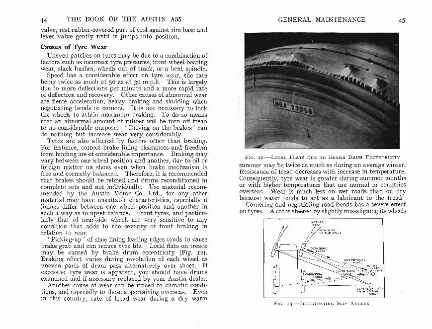
44 THE BOOK OF THE AUSTIN A3S GENERAL MAINTENANCE 45
CE NTRE OF TuRNW IT H 1\,10SLI P
A NG LE
valve, rest rubber-covered part of tool against rim base andlever valve gently until it jumps into position.
Causes of Tyre WearUneven patches on tyres may be due to a combination of
factors such as incorrect tyre pressures, front-wheel bearingwear, slack bushes, wheels out of track, or a bent spindle.
Speed has a considerable effect on tyre wear , the ratebeing twice as much at 50 as at 30 m.p.h. This is largelydue to more deflections per minute and a more rapid rateof deflection and recovery. Other causes of abno rmal wearare fierce acceleration,heavy braking and skidding whennegotiating bends or corners. It is not necessary to lockthe wheels to attain maximum braking. To do so meansthat an abnormal amount of rubber will be torn off treadto no considerable purpose. 'Driving on the brakes' cando nothing but increase wear very considerably.
Tyres are also affected by factors other than braking.For instance, correct brake lining clearances and freedomfrom binding are of considerable importance. Braking mayvary between one wheel position arid another, due to oil orforeign matter on shoes even when brake mechanism isfree and correctly balanced. Therefore, it is recommendedthat brakes should be relined and drums reconditioned incomplete sets and not individually. Use material recommended by the Austin Motor Co. Ltd., for any othermaterial may have unsuitable characteristics, especially iflinings differ between one wheel position and another insuch a way as to upset balance. Front tyres, and particularly that of near-side 'wheel, are very sensitive to anycondition that adds to the severity of front braking inrelation to rear.
, Picking-up' of shoe lining leading edges tends to causebrake grab and can reduce tyre life. Local flats on treadsmay be caused by brake drum eccentricity (Fig. IZ).Braking effect varies during revolution of each wheel asuneven parts of drum pass alte rnat ively over shoes. Ifexcessive tyre wear is apparent, you should have drumsexamined and if necessary replaced by your Austin dealer.
Another cause of wear can be traced to climatic conditions, and especially to tho se appertaining overseas. Evenin this country, rate of tread wear during a dry warm
F IG . 1 2 .-LoCAL FLATS DUE TO BRAKE DRUM E CCE NTR lCITY
summer may be twice as much as during an average winter.Resistance of tread decreases with increase in temperature.Consequently, tyre wear is greater during summer monthsor with higher temperatures that are normal in countriesoverseas. Wear is much less on wet roads than on drybecause water tends to act as a lubricant to the tread .
Cornering and negotiating road bends has a severe effecton tyres. A car is steered by slightly mis-aligning its wheels
FIG. 13.-ILLUSTRATING SLIP A N GL E S

THE BOOK OF TH E AUSTIN A35 GE NERAL MAINTENANCE 47relati ve to direct ion of travel. This applies equally to reart yres as to front ones. Resulting t yre slip and distortionincrease rate of wear according to speed, load, road camberand other factors (Fig. 13).
When drawing up to kerb , or parking against it, careshould be exercised to prevent what ar e known as ' impactfractures' causing damage to casing cords. Sometimesthis damage is caused without owner being aware thatanything unusual has occurred , initial shock having beenabsorbed by tyre and road springs . It is des irable to renewcover when firs t signs of dam age are noticed, for later itmay suddenly fail completely and a 'blow-out' can havedisastrous results if your ar e trav elling at speeds.
It is of the greatest importanc e that wheels are alignedand this detail should be regularly checked (see page 57).Mis-alignment causes lateral wear on tread because, asalready mentioned, natural direction of whee l differs fromthat of line of travel.
Keep an eye on front tyres and part icularly on theirtreads. Due to the' camber ' of the front wheels the treadwill wear more on one side than the other but any condition such as ' feather-edges' (Fig. 14), or uneven patches.
F IG. 1 4 .-' F E ATHE R EDGE' DUE TO WHEEL M IS -A LIGNME);T
should be suspect . 'Feather-edges ' can be felt on a t yr eby drawing the fingers across the tread first in one directionand then the other. If a distinctl y sharp edge can be feltthen the wheel toe-in requires correcting (see page 58).
Uneven patches on the tyres ma y be due to a combinationof factors such as incorrect t yre pressure, front-wheel bearing wear , slack swivel-pin bushes, wheels out of track , or abent spind le.
When bu ying new t yres always buy those of a kn ownmake. A set of tyres will normally run man y thousandsof miles and the difference in cost between a good makeand an inferior one is really trifling. An inferior tyre maylet you down at a most in convenient moment and then youfeel it was not really so cheap after all.
Equalizing Tyre WearTo equalize t yr e wear it is a good plan every 5 ,00 0 miles
t o change front whee ls to rear. This prevents undue wearon an y individu al t yr e by compensating for different kindsof wear experienced in front and rear wheel positions.Also, bring spare wheel into this plan, for it is bad policyto allow a new spare t yr e to remain idle unti l other t yr esare being worn out as it may det eriorate from lack of use.
Diagonal interchanging betw een near front and off lear,and between off front and near rear position, provides themost sat isfactory alternation, for it reverses direction ofro tation for each wheel (Fig. 15).
FIG. 15 .-TY RE R E-P OSITI ONI N G

48 THE BOOK OF THE AUSTIN A35
Change the wheels as follows :Spare t o off-side rear.Off-side rear to near-side front.Near-side front to near-side rear.Near -side rear t o off-side front.Off-side front to spare .
Wheel BalancingCorrect rot ational -balan ce of all wheels, and particula rly
of front ones, is essential if smoo th high-speed running andlong tyre life are to be ob tained . It is particularly necessaryon all cars having independent front suspension. Itobviates vibrat ion , steering wheel t remor, and ensuresprecise steering.
Wheels and tyr es should be stat ically and dyn amicallybalanced after every tyre chang e. When a new tyre isfit ted-or if it should be suspected that in normal use tyreand wheel balan ce have been affected- rotat ional balanceshould be checked . Your Aus tin dealer may have amachin e that enables balance to be checked and, if necessary, corre cted without remo ving the wheels.
Tyres are now mad e with coloured spots on bead toindicate lightest parts (F ig. 16). 1£some tyres are slightly
F IG. r 6 .-TY RE B ALAN CI NG
Coloured spo t should be at the valve posit ion for tubeless tyres
outside standard balanc e limits they are corrected beforeissue, T his is done by attaching loaded patches insidecov r casing. In order that these are not mistaken forrepair patches they are embossed 'Balance AdjustmentRubber '. These patches, or somet imes discs, should onno account be removed or balance will be up set .
Original balan ce subsequently may be affected by unevent read wear or by repairs. Also, the car may become 'increas ingly sensitive to unbalan ce due to normal wear on
GENERAL MAINTENANCE 49
moving parts. Should roughness, or high-speed steeringtroubles develop, wheel and tyre balanc e should be checkedand adjusted.
Jacking-up the CarThe Austin A35 is provided with two points for using
the type of jack kno wn as Smith's' St eady-lift'. One oft~ese p?ints is underneath each side of vehicle, enablingeither n ght or left side to be raised. As the front and rearwheels on either side are raised there is no need to insert thejack under either axle. The effort required to raise the carwith this jacking system is relatively small.
A fe'Ywords ab?ut jacking-up. . ~f possible, never changean offside wheel in a road on which there is a continualstream of t raffic. Should it be impract icable to turn offthe road into a qu iet lan e or lay-b y, dri ve to the other sideso that the wheel to be changed is on the side away fromthe passing traffic.
Before jacking-up make sure that there is sufficient roombetween the car and the curb for the wheel to be lifted offthe hub when raised.
The next thing to do is to apply th e handbrake firmly.Re~ove. the ~pare wheel from the luggage compartment ,placmg It adjacent to the wheel that is to be changed .Thus the car is not standing without a wheel any longerthan is necessary.
Before fittin g, test the pressure of the spare wheel tomake sure that it is fully inflated.
No.w re!l10ve th~ hub di.sc that covers the wheel nuts bylevenng It off WIth a com or screwdriver applied at theedge. The road-wheel nuts should be loosened a little ata time and then the car is ready to be jacked up .
Open the front door and insert the jack lug into the socketpro~ded under the vehicle (Fig. 17). Be certain that thelug IS fully engaged in the socket and also that the baseof the jack has a firm footi ng on the ground. Now attachto the hea.d of the j.ack the wheel-nu t brace supplied inthe t ool kit. Turn in a clockwise dir ection to raise thecar off the ground on the side to which it is attached .
Remove the br ace from the jack, unscrew the wheel nuts,. remove the wheel and fit the spare wheel.
Enter the nuts, coned ends first, so that the wheel is

50 THE BOOK OF TH E AUSTIN A3S
F IG. I 7 .- S MIT H ' S ' S TE AD Y -LI FT ' JACK
correc tly centra lized . Slightly t ighten up each nut dia gonally, a little at a time, to ensure that the wheel seatsevenly against the hub.
Lower the car to the ground by turning the brace anti clockwise and so release arid detach the jack.
Fin ally , tighten the wheel nuts with the wheel-br aceand fit the disc cover.
Check the nuts of the wheel you have just fitted at theend of the day, afte r which they should remain secureind efinit ely.
CHAPTER IV
STEERING GEAR
T HE STE E RING GEAR of the Austin A35 is of thecam-and-lever type with a ratio of 12 : I, giving easy
manceuvrability when negotiating sharp corners. Th esteering box , which is mounted just forwa rd of theto e-board ,provides a short st eering column of great rigidity. A crosst ube run s behind the engine and gives the steering mech-anism ample protect ion. .
The lower end of the steering inner column terminates ina cam mounted on ball races. The rocker shaft to whichthe double lever is bolted has a short cam lever at its inn erend with a conically shaped peg pressed into contact withthe cam groove.
As the steering sha ft is turned, the peg follows the groovein the cam. This partly rotates the rocker shaft movingthe double lever and this, in turn , actuates the steeringlinkage and front wheels.
In the steering linkage, which has ind ependent fron twheel suspension, one of the tubes- referred to as sidetubes-is connected directly to the front arm of the doublelever of the steering gear. Its other end is joined to theswivel arm of the right-hand wheel. To the rear end ofthe double lever is conn ected the cross-tube . It transmitsmovement to the left -hand wheel through the medium ofan idler shaft and bracket. This is bolted to the other sidememb er, symmetrically opposite in mounting to the st eering gearbox, again with a double lever. From the rear ofthis idler lever is another side-tube connected to the wheelby way of its swivel arm. This method of connecting thesteering gear to the fron t wheels-through equally mountedside-tubes-ensures that as each wheel rises and falls, dueto normal road inequ alities, any deviati ons will be equalfor each wheel.
The working parts of the steering gear operate in oil.Providing that the level is correctly maintained, long servicewill be enjoyed before any adjustment is required.
51

any more . Re-check the adjustment in case this has happened. It is permissible for the st eering gear, with bothwheels jacked up, to have very slight ' drag' at this centralposit ion but there must be no undue resistance.
Another poin t at which th ere may be wear is the steeringwheel shaft . This may be gauged by grasping the stee ringwheel firmly with both hands and by alternately pushingdown and pulling up along the length of the column. Ifend-float is felt, it will be necessary to remove the steeringgearbox end cover to extract the adjustment shims.
At th e lower end of th e stee ring box is a hexagon glandnut. It locks the long stator tube in its correct relativeposit ion. Provided that the end cover is marked so thata known edge is to the top, th e sta tor tube need not befur ther removed.
As the removal of the end plate will allow the oil toescape, use a receptacle to prevent messing the floor.
Removal of ShimsUnscrew the four bolts of th e end plate and move it
downwards sligh t ly, disclosing the adjustment shims fittedbetween it and the steering box. These shims are of twotypes-s-brass and steel. Remove one at a time and afterthe removal of each, ' bolt up the end plate and re-test. Ifthey are not removed thus the elimination of several shimsat a time may unduly tighten the ball rac es causing themto wear rapidly as well as making the stee ring stiff. Shouldyou suspect that the bearing ad justment appears to be tootight, a quick check ma y be made by loosening slightlysay half a turn each-the four end-cover securing bolts.If th e steering now appears to be free it indicates that toomany shims have been removed. Therefore, a suitablenumber must be refitted to obtain the correct adjustment .
A stiff steering gear is sometimes traceable to th e columnitself having been st rained and out of position. Try theeffect of loosening the column -support bracket allowing thecolumn to move into it s normal unrestricted position. Ifthe column in this position is now free, the steering boxmounting and bracket should be set so that th e columncan be bolt ed into position without placing any undueconstraint on it .
52 THE BOOK OF THE AUST IN A3S
The linkage connecting the double lever and cross-tubesis of the ball-and-socket type and regular lubricat ion willeliminate any other attention for a considerable time.
The steering box has ad justments for wear but it isst rongly advised that if adjustment becomes necessary youshould ask your Austin dealer to carry this out. Unskilled attempts can cause tight adjustment resulting inheavy st eering and accelera ted wear or ' back-lash' (unduemovement), contributing to ' steering wander '.
It may be that you find it necessary to effect some adjustment yourse lf, however , and if these instructions are carefully followed you should be able to do it satisfactorily.
Before ad just ing, it is desirab le to ascertain exactly whatwear is present and where it ha s taken place. The firstsymptom is either excessive movement at the steering wheelbefore th e road wheels move, or a t endency for wheelwobb le or ' wander' to develop. This may be due tolink age wear and not to wear in the box. The followingtest should disclose the source of the trouble.
Have someone slowly turn the steering wheel first oneway and then the other whilst you prevent the road wheelsfrom moving sideways . Note any signs of lost motion atthe stee ring linkage connection . Do not forget that theseconnections are held in t apered holes in the swivel-armsand double levers. If allowed to become loose, they maywear oval. This is a condition that subsequent tighteningwill not correct as a true seating is then no longer possible.
Assum e the wear is found to be in the steerin g box.Gra sp the double lever and see if this can be pu lled andpushed , so bringing the end in the box nearer to or furtheraway from the cam . If movement is found at this pointth re is an adjustment whereby it can be taken up. Ont he side cover towards the top is a hexagon-headed screwwit h a locknut fitted to it. Loosen this locknut and carefully tu rn the adjusting screw clockwise a lit tle at a timeunti l the end-flat is taken up . Remember that the camis so constructed that there is least ' back -lash' when thewheels are dir ect ed straight ahead. Therefore, alwaysadjust with the wheels in this position otherwise the steeringwill be unduly sti ff at the central position.
Wh en the correct adjustment has been obtained securelytighten the locknut making sure the screw does not turn
STEERING GEA R 53

sam e way. Inspect th e rocker shaft for wear at th e pointwhere it is moun ted in its bearing bush. Also, inspect thecam for wear in the grooves and at the b';l.ll tra~ks that ~orm
its bearings. Wear at either of these pomts WIll necessitaterenewing the unit. .
The corresponding ball cups should be examined forwear and if they are pitted they shou ld be renewed. Bothcups are replaceable.
Thoroughly wash all parts ready for reassembly.
ReassemblingInspect the cork gland at the ou~side end o~ the ~r?ss
shaft an d replace if necessary . I t IS secured in posi tionby a steel washer to be ret ained in place by lightly peeningover th e metal at three points around its circumference.
Place the steering outer column in the vice so that th eend of th e box is pointed upwards with the steering-wheelend to the bottom.
Assemble the ball cages and cups (if removed) and installth e inner column. Refit the end cover and shims, tighten-ing the four bolt s secure ly. .
Temporaril y reassemble the stee~mg wheel. and test forend float or, alte rnatively, for too tight an adjustment (seealso page 53). The correct adjustment is when th ere isno end float but just a slight ' dr ag ' . Remove or addshims between the steering box and end cover until thi ssetting is achieved. "
The upper bush- ju t b~neath t he ~teenng wheel-s-isreplaceable but is scarcely likely to require renewal exceptafter very considerable use.
The upper shaft bush is of a felt material. A new ~elt
should be first soaked in engine oil and inserted by pushmgone corne r between the inner column and outer tube.Then gradually work the remainder into position with ascrewdriver or similar tool. It is advisable to ap ply gra phite to the part of the felt that makes ~ontact with thesteering shaft . Apply a few drops of oil here every 500miles.
Next , oil th e rocker sha ft and ball peg and .insert intoposition in th e box, the peg to enter th e groove m the cam .
Undo the locknut of the side cover plate and screw bac kthe' adjusting screw severa l turns..
54 THE BOOK OF THE AUSTIN A3S
The correct steering ad justment is when a very slight, dr ag ' is felt as the steering 'Yheel is turned from lock tolock with the front wheels raised .
Do not forget th at removing the end-plate will haveallowed all the oil in th e box to escape. Therefore , refillthe box to level of orifice.
Overhauling Steering GearPossibly the owner may find it necessary to overhaul.the
steering gear when ad justment no longer becomes effechv~ .
The same advice applies here also-do not attempt thiswork unless you feel you have sufficient mech~nical skill.At the outset it should be pointed out that special tools arenecessary for th e removal of the steering wheel and thedouble lever. Both part s are secured on tapers and haphazard attemp ts t o remove them without pr oper toolswill either be abort ive or will cause damage.
If you have decided to do the work yourself, first takeout emblem cap set in hub of stee ring wheel by gel?-tlyprising it with a screwdriver. Next unscrew steerm~
wheel nut and withdraw washer . Remove cotter pmsecuring castellated nut holding double lever to rock~r
shaft . A special extractor will hav e to be used to draw thisoff its tap ered mounting. . .
Unscrew bolts at edges of side cover and lift It off thebox. Draw rocker shaft out of its bushes in steering box.
Before the stee ring inner column can be dismantled thefour bolts holding the end cover must be un screwed .Ext ract the key on the stee ring-wheel taper and drawthe inn er column out of the stee ring-column tube . Themajor parts of the steering gear may now be inspected indetail (Fig. 18). . .
Inspect t he rock er shaft for wear on the ball peg. T~lS ISa press fit in the lever an d ISreplaceable. Look for twist edsplines and if any are found the shaft. must be renewed .
Inspect the face against whl.ch th e adJus~mg screw ab~ts
for it may have been scored If at some time th e st~enng
gear has been adjusted t<:>o. t ightly or operate~ WIthoutsufficient lubricant. Providing that the scon ng IS not toodeep the face can be rest ored by carefully grinding. it ~at
on an oil sto ne. At the same t ime examme the adJl;lstmgscrew for similar signs of wear and if necessary treat in the
STEERING GEAR 55

THE BOOK OF THE AUSTIN A3S STEERING GEAR 57
FIG. I S.-COMPONENTS OF CAM T YPE S TEERING U NIT
I Steering-wheel Securing Nu t. 2 Felt Bush for Inn er Column. 3 Peg, and 4 RockerShaft. S Housing for Gear . 6 Side Cover. 7 Washer and 8 Oil-Filler Plug. 9 Thrustscrew Locknut and 10 Screw. I I Cover Set-screw, 1 2 Side-cover Joint and 13 Endcover J oint Washers. I4 Ruhber Ring for IS Top Bearing Retaining Cup (for assemh lyonly) . I 6 Bearing Ball Cups and Balls. I 7 Shims for Adjustment. I 8 End Cover .I 9 Set-screw and Washer. 20 Cam and Inn er Column . 2 I Cork Sealing Washer.2 2 Retainin g Disc. 23 Steering Side and Cross-tube Lever. 24 Lock or Plain Washer-,
25 Nu t and Spli t Pin
Oil the surfaces of the ad justing screw and cross shaftwhere they touch one another.
Fit a washer between the box and side cover and boltit up secure ly,
Refit the double lever notin g that both it and the shaftare marked to ensure reassembly on the correct splines.Tighten up the castellate d nut and lock it securely with anew cotter pin.
Adjust the rocker shaft by means of the adjusting screwso that at the central position there is no end float nor isth e steering at this point stiff.
Refit the steering gear in the reverse mann er from thatwhen removing.
One or two points require care, however. Do not tightenup the three bolts holding the steering box to the sidemember until the strap at the instrument panel has beenassembled.
When reconnecting the steering linkage, t ake care thatthe tapers on the connect ion and in the outer end of thedrop arm are clean and that the nut is pinned when tight .
If the steering-box bolts are first tightened it may bethat the stee ring column will not line up with th e bracket.If secured in this manner it will be st iff and undue bearingwear may ensue (see also page 53).
Re-attach the lighting switch to the steering column.
Adjusting Front Wheel Toe-inFor technical reasons, into which it is not necessary to
enter , the front wheels must either be exactly parallel orpoint towards each other slightly at the front . An equivalen t measurement , taken at hub height at the front of thewheels, is 16 in. to i in . less than at the rear (Fig. 19).They must not toe-in more than i in ., otherwise tyre-wearwill result and the stee ring itself will not be as accuratenor as responsive as it should be. If it does appear thatthere is considerable toe-in or toe-out, it may be th at onewheel has been bu ckled slightly or possibly the tyre is notrunning true. Before proceeding further in such cases, itis as well to spin each wheel to establish if any of the abovecondi tions are present. Always test for front -wheel toe-inwith the wheels in the ' straight -ahead ' position.
To adjust the wheel toe-in loosen the locknut at eachend of th e cross tube remembering that one end has aright-hand and the other a left-hand thread. With allthese nuts loose it is only necessary to turn the cross tubein the required direction. This will have the effect ofmoving both wheels nearer together, or further apart,according to the dir ection in which the tube is turned.Wh en the correct setting ha s been obtained securely tightenboth locknuts.
E

58 THE BOOK OF THE AUSTIN A3S
It is a matter of some difficulty to measure to e-in without special appara tus but you may find it practicable todevise a suitable make-shift gauge from a wooden strip.Cut this t o such a length that it will exactly enter between
F IG. 19.-To E -IN BETWEEN WHEEL R IMS. A is l .' t o t in .Less t han B
the t yre walls at the front of the wheels. Provide yourselfwith two rests so that when the wooden strip is restingon one at each end it is at hub height. Assuming the woodstrip is a snug fit between the wheels at the front thenwhen similarly installed at the rear of the front wheelsthere should not be more than k in. play.
CHAPTER V
SUSPENSION
I T IS ONLY NATU RAL that owners should discuss theperformance of their respecti ve cars. Next to perform
ance the quest ion of the springing, or suspension, generallyis either praised or blamed. Th e suspension of a car isnot merely the method of springing used. Th ere are man yother factors that whether taken singly or collect ivelycontribute to comfortable riding. For instance, on twosimilar cars one driver who may habitually drive alone willexperience a somewhat different ' ride' as compared withan owner who carries thr ee passengers or an equivalentload. Therefore, the designer has t o bear in mind theset wo extremes in pro ducing a suspension system that willbe satisfact ory under widely varying condit ions.
The Austin A35 is fitted with semi-ellipt ic underslungreverse camber leaf springs at the rear. At the front thereis independent suspension employing large coil springs andwish-bones.
R~ad Springs and Rear AxleTwo factors that have a considerable bearing on suspen
sion are neglected springs- these t end to become stiffand tyre pressure. Too Iow a pressure contributes to roll,whilst too high a pressure t ends to produce pitching andhard suspension generally.
Provided that the springs are lubricat ed regularly andthe tyre pressures checked (see page 38) the rear suspension should be found sat isfactory for all normal conditions.E ach rear spring has eight leaves and between the topfour leaves three zinc st rips are inserted. These preventsqueaking and undue wear by virtue of their natural non rusting qualities.
The spring eyes at each end have silent-bloc bushesrequiring no lub rication. At the rear a spring shackle isfitted, one end of which is carried in the silent-bloc bush ,the other in a bracket attached to the chass is frame. This
.59

60 THE BOOK OF THE AUSTIN A3S SUSPENSION 6Ibr acket locating the shackle to the chassis frame needsweekly lubrication with the grease-gun. Access is obtainedby removing the ru bber plug situated at each side of theluggage compartment floor.
F IG. 2o.-REMOVING BUSH FROM SPRING-EYE
Do not be t empted to apply any oil to the silent-blocbushes under the impression that it will improve their wearing qualit ies. In actual fact, it will have the reverse effect.
Rear Shock Absorbers and Anti-roll BarAn ingenious, yet simple, dev ice is ? tted to the rear a:cle
to minimize body sway or roll such as IS caused by corneringor abnormal road conditions . In effect, this device consistsof a steel bar mounted across the chassis frame parallel toand in front of the rear axle. An arm is extended at eachend and bolted to the hydraulic shock absorber at bothsides whilst a rubber-bushed link connect s the end of eacharm to the rear axle itself. (This device is illustrated inFig. 20.) Suppose the car hits a bump that moves the axleupwards. Since the anti-roll bar is connected to the shockabsorber levers, normal hydraulic control is obtained sofar as rebound and compression are concerned. Should one
wheel move upwards or downwards to a greater degreeth an the other, however, then this movement will be resisted . This takes place becau se instead of the bar movingup or down as a whole one end only moves and considerableresistance is then deve loped. From this you will see that-t he ant i-roll bar pr events undue side movement of the bodyand tends to give steady and smooth suspens ion. Theshock-absorber opera tion and maintenance is describedlater in this section.
Front SuspensionEach fron t wheel is mounted on a type of front suspe n
sion usually called the' wish-bone' because the upper andlower arms take this shape . This system permits the frontwheels to move up and down according to the inequ alitiesof the road surface, at the same time assu ring that corre ctsteering geometry shall exist. Between the lower wishbone member and the chassis frame is fitted vertically alarge helical compression spring in such a manner as to
3
F IG. 2I.-FRONT SUSPENSION L U B RI CATION P OI NTS
I Swivel Axle-pin Top Bush. 2 Swivel Axle-pin Bottom Bush. 3 SuspensionLower-link Bushes

62 THE BOOK OF THE AUSTIN A3S
cause the wheel to absorb road shocks. A conical rubberpad fitted within this spring prevents abnormal loadingfrom causing the suspension to ' go solid'.
The top wish-bone member incorporates a hydraulicshock absorber. Although its external appearance differssomewhat from that fitted on the rear axle, the operationis the same.
The upper and lower wish-bone arm takes the place ofthe front axle beam. Provided that the various workingparts are lubricated periodically they should give goodservice . - I t will be found that at some points there arerubber bushes. These require no lubrication but the otherbearings fitted with lubricators must be lubricated, especially where they meet axle swivel housings (Fig. 21). Thereare two lubricators, one ben eath upper wish-bone arm, theother above lower wish-bone arm.
Swivel axle has an ' oilit e ' washer mounted to absorbfriction caused when wheels turn from side to side asst eering wheel is rotated. This thrust washer and swivelaxle bearings are lubricated through two nipples to whichreference has already been made.
Checking for VVear
Should it be suspected that there is wear within the frontsuspension the following method will assist in diagno singthe trouble. First, wedge the rear wheels S0 that the carwill not move. Release the handbrake and .jack-up thefront wheels, one at a time.
Grasp the front wheel 'with both hands, one at the top,the other at the bottom. Now try to rock the wheel , andif movement can be felt, this may be due to wear at theking-pin bushes or at the hub bearings. If the hub bearings have worn, movement between the brake drum andthe brake plate can be seen or felt.
By grasping the wheels with the hands in a horizontalposition and moving each to and fro, any lost motion orwear in the steering linkage can be traced. This is a matterwhere a friend to look out for movement is most helpful.
In course of time, a little wear may develop in the rubberbushed ends of the wish-bone arms as well as in the metalbushed ends . But there is little the owner himself can do
SUSPENSION 63
about this for dismantling the front susp ension is not aneasy matter.
Front Shock AbsorbersThe shock absorbers, sometimes overlooked, play an
important part in damping-out road shocks and checkingany tendency to ' pitch' on wavy road surfaces.
Armstrong shock absorbers are fitted to the front andrear suspension . Their shock-absorbing property is obtained by using a piston to force a quantity of fluid througha small orifice so causing a resistance. The valu e of thisresistance is less when the axle is moving upwards thanwhen it rebounds or returns. This feature is obtainedautomatically by a system of spring-loaded valves containedwithin the body of the shock absorb er.
The front shock absorbers ar e mounted in such a positiont~a.t the upper wish-bone arms connect directly to them,glvmg a neat and simple method of incorporating themwithin the suspension linkage.
Rear Shock AbsorbersEach rear shock absorber is mount ed on the chassis side
member directly above the axle. The operating arm of~he shock absorber is coupled to the axle by a link thatmcorporat es rubber bushes at each end thereby obviatingthe necessity for lubrication. No lubrication at either endof the link is required and the addition of oil will onlycause deterioration. In deed, care should be taken to seethat they are kept free from grease or oil. If oil or grease
,finds its way into them, clean off with warm water at once.The rubber bushes are part of the operating arm and cannot be renewed. If they become worn, new arms shouldbe fitted.
Maintenance and TestingThe design of the shock absorbers is such that they will
function for long periods. All that is necessary is to checkthe fluid level and top up if required every 6,000 miles.
Two important points to remember are :
(a) Grit .or dust, the natural enemies of highly loadedworkmg parts, must not be allowed to enter the
64 THE BOOK OF THE AUSTIN A35
shock absorbers. Before unscrewing the filler plugit is essential to clean around it so that when it isremoved no dirt will fall into the orifice.
(b) The shock absorbers operate hydraul ically and onlythe recommended fluid should be used. An unsuitable oil can damage the working parts and an incorrect grade will alter the characteristics of itsresistance.
After cleaning around the filler plug, unscrew it readyfor topping up if required. The fluid level at the rear canbe seen by using a small mirror and pocket t orch. Foradding fluid a force-feed oil-can is most convenient . Donot mix engine oil and shock absorber fluid in the samecan.
The design of the lid or cover is such that when filledto the bottom of the orifice sufficient air space is left toallow for natural expansion of the fluid that occurs as theshock absorber warms up in use.
Periodically inspect the lever shaft at the point where itenters the body and note any signs of fluid leakage. Ifthere is a consist ent leak at this point it indicates that thegland, and possibly the bearing, has worn and the shockabsorber should be overhauled. This is not an operationthat you can carry out yourself, so your Austin dealershould be consulted.
At some time you may feel that the suspension is notwhat it was and you may probably suspect the shockabsorbers as being responsible. Thi s is a matter that canbe determined as follows:
Remove the anti-roll bar from the shock-absorber leverand carefully disconnect the link from the rear axle.Grasping the link you may then raise and lower it betweenthe extremes of its travel. If no real resistance is felt theshock absorber may require refilling. Do this and againtest, bearing in mind that it will take several strokes forthe fluid t o be circulated within the internal passages andto bui ld up it s normal resist ance. Heavy resistance maymean that an unsuitable oil has been used-possibly twodifferent oils have been mixed-or there may be somederangement of the internal mechanism.
It is not practicable to give precise resistance figures that
SUSPENSION
could be used as a guide. In general, when testing thesh~ck absorber the lever should move st eadily with equalresistance for the whole extent of its travel in one direction.The effort. required toyush up the lever is slightly less thanthat required to pull It down. If you gain this impressionwhen testing and if it takes you several seconds to movethe lever through one complete stroke then it may beassumed that all is well.
If you still suspect that the riding qualities are not whatthey were, check the road springs and shackles for correctlubrication and the tyres for correct pressure.
Finally, examine the springs themselves as sometimesa leaf breaks and the axle may then bear on one of therubber rebound pads causing rough suspension.

CHAPTER VI
BRAKING SYSTEM
EF FICIENT BRAKES are not only a necessity toenable the car to be controlled on the road but the
law requires that any braking system sha ll conform tocertain standards. It also requires that brakes are kept insuch mechanical order as to permit the car to be used wit hsafety under all conditions . Therefore, apart from theowner's natural desire to have efficient brakes rea dilyavailable whenever th ey may be needed, he must also
F IG. 22.-BRAKING SYSTEM
remember that at any time the police may require ad monstrat ion of their complete efficiency.
It is not always appreciated that much of the pleasurein driving a car is dependent to a considerable degree onth driver 's confidence in his brakes. Two particularsymptoms th at cause the driver acute anxiety are harshbraking and inefficient braking, i.e . when efficiency is soreduced that un due force has to be used to apply thebrakes.
Harsh braking can not only cause the car to skid-sometimes uncontrollably in wet weather-but it also imposes
66
BRAKING SYSTEM
severe strain throughout the transmission. It is directlyresponsible for undue tyre wear. On the other hand, poorbraking gives the driver an unpleasant feeling that he maynot be able to stop in time should some vehicle in frontdraw up sud denly.. No matter how well designed the braking system may beIII the first place- and the Aust in system certainly is welldesigned-it is materially affected by the periodic attentionit receives . Neglect is soon shown by stiffness in the working parts with resultant loss of efficiency.
F IG. 23 .-BRAKI NG SYSTEM
Top : When brake pedal is depressed hydraulic pressurecauses push rod to move stirrup forward to operatet he brakes. B~ttom: Handbrake operates d irectly on
stirrup as shown by the arrow
Th erefore, it is the dr iver' s responsibility to see that hisbrakes are correctly adjusted and are in thorough workingcondition at all times.
Front and Rear BrakesThe brakin g system of the Austin A35 is designed to
operate for .long periods without the necessity for adj ust ment, provided that periodic lubrication is carried out.Th e various points requiring attention are shown on thelubrication cha rt (see page 206).

68 THE BOOK OF THE AUSTIN A3S BRAKING SYSTEM 69The brake pedal operates shoes on all wheels through
the hydraulic system. On the front wheels the brakeshave two leading shoes. Thi s type of braking enables anextremely powerful braking effort to be obtained with aminimum of mechanical effort. Brakes on the rear wheelshave one trailing and one leading shoe in each drum. Thisarrangement not only permits satisfactory braking in allconditions but also has the additional advantage of permitting the car to be held on severe gradients withoutundue effort .
Th e method of app lying the front and rear brakes relieson a master cylinder (Fig. 24), pedal-operated and connected to hydraulic' slave ' cylinders on each front wheelwith an expander unit on the rear wheels. On each frontwheel two brake cylinders actuate the leading brake shoes.At the rear a hydraulic cylinder and a push rod actuatetwo shoes through mechanical linkage (Fig. 23).
The pipe line connecting maste r cylinder to cylinders onfront wheels is attached to the frame by a flexible pipe.This allows for rise and fall that nat urally takes place at thispoint due to movements of road wheels relative to chassis.
The foot-brake pedal, mounted on chassis side member,is connected to mas ter cylinder through the medium ofa rod so that when the pedal is depressed the rod movesrearwards. In turn, this pushes down the plunger inmaster cylinder thus forcing fluid under pressure to thebrake cylinders (Fig. 25).
The handbrake lever opera tes rear shoes by linkage between it and rear-cylinder push rod. Thi s causes stirrupto move and so to apply rear brakes in a similar mannerto foot operation of the brakes (Fig. 25).
A reservoir, or supply t ank, is fitt ed under the cover plat elocated to right of gear lever on the floor (Fig. 26). Thefluid it contains is permitted to ente r the master cylinderthrough a suitable connecting pipe and union.
It is important that no other fluid than the correct gradeof hydraulic fluid should be used when the system is replenished.
The use of an unsuitable fluid such as a mineral oil, couldcause rapid deterioration of oil seals, thus preventing thesystem from working correctly.
As already described, on the front wheels there is anhydraulic cylinder to each brake drum. One end of each
M....
;!j---t\-..ll....'LI
;!l - - - - -

70 THE BOOK OF THE AUSTIN A3S
F IG. 25.-REAR CYLI NDER
I Ex pander Spring. 2 Rubb er Cup . 3 Cylinder Body. 4 Pu sh Rod.'5 Rubb er Boo t . 6 Pist on. 7 Cup Expander. 8 Bleeder Screw
FIG. 26.-BRAKE FLUID RESERVOIR
I Cover Pl a te. 2 Filler Cup . 3 Cover-plate Securing Screw.
shoe rest s on an abutment that forms a stop. The otherend is attached to the piston and expands when the brake
BRAKING SYSTEM 7I
pedal is depressed. Each shoe is separately operated sothat the moving ends face the direction of brake-drummovement. Thus, a powerful braking effect is obtainedbecause of the 'leading-shoe' effect .
The rear brakes are operated by the cylinder shown inFig. 25, located at the rear off side and secured under thefloor-boards. When brake pedal is depressed, fluid fromthe master cylinder causes cup 2 to thrust outwards piston 6and push rod 4. This push rod abuts a stirrup and thismoves with it. Attached to it is a pull rod and this,through mechanical linkage, causes the lever to be thrustoutward until the brake shoes are bearing against the drum.
Because only one shoe in each rear drum is ' leading' , asomewhat less powerful effect is obtained. This is intentional, however , for th e design is intended to produce agreater proportion of braking on the front wheels.
The other end of each pair of rear brake shoes is mountedon the abutment that acts as a stop. An ingenious meanswithin this abutment enables an adjustment screw to expand th e shoes to take up any lining wear that may occurnaturally in cour se of time. This screw has a slotted endand as it protrudes through th e brake plate it is easilyaccessible for adjustment when requ ired .
Every I,OOO miles check level in brake fluid reservoir .This should be ! in. below filler opening. To gain accessto reservoir pull back carpet from under foot pedals toreveal a metal cover plate in the floor . This plate can beremoved aft er releasing th e two fixing screws renderingthe reservoir cap accessible (Fig. 26).
The brake linkage itself is adjust ed at the works. . Resetting will not be necessary provided that the linkage isregularly lubricated and inspected to ensure that the nutsdo not become loose (Fig. 24).
Apart from periodically topping-up master cylinder andadjustin g brake shoes as required, there should be no necessity for the syst em to be disturbed in any way.
It cannot be too strongly st ressed that braking efficiencycan be completely upset unless adjustments are correctly made. Consequently, if you have any doubt aboutyour ability to make them as necessary, you will be welladvised to ask your Austin dealer to carry out the work .
To maintain your braking system in efficient condition by
.-

FIG. 28.- FRONT BRAKE ASSEMBLY
I Brake Linin gs and 2 Shoe. 3 Wh eel Cylinder. 4 Slotted Adjusting Screw. 5 Flex ibleBrake-hose. 6 Cylind er Bridge Pip e. 7 and 8 Large and Small Fi xing Bolts 9 Back
plat e. 10 Clicker Wh eel. II Dus t Cover . 1 2 Pull-off Springs '
Before proceeding fur ther, unscrew brake supply t ankcover and if necessary add fluid to maintain correct level.Loosen bleed nipple- ab out three-quarters of a turn will besufiicient .
All that is now needed is to operate the foot-brake, usingregular steady strokes between the limits of its travel, but
73BRAKING SYSTEM
A B
72 THE BOOK OF THE AUSTI N A3S
using brake-shoe adjustment pro vided for brake plates,see page 74.
Bleeding the Braking SystemWhen the master-cylinder pist on is moved rearwards it
compresses the fluid in the system, causing each slave pistonto move and so applying brake shoes. Although the fluidis only under pressure when brake pedal is depressed, it isimport ant to keep the system completely filled with fluid,otherwise air may enter. As it is compressible it willprevent a full braking effect being obtained. The presenceof air in the syst em is evidenced when the brake pedal nolonger feels' solid' but has a ' spongy' feeling. Provided
FIG. 27.-BRAKE B LEED NIPPLE
A: Rubber Cover. B: Bleed Nipple
that the maste r brake-supply tank has been inspected andt opped up as necessary, air should never ente r the system.However, if it is felt the system requires bleeding, due to thebrake pedal feeling' spongy ', proceed as described below.
Obtain a jar, a length of rubber pipe, and a spanner ofa size to fit the bleed-nipple hexagon at B, Fig. 27. Then,partly fill the jar with clean hydraulic brake fluid. Arubber cover (A) act ing as a dust cap is fitted over thebleed nipple. Pull off and retain this cap and ente r oneend of the tube on the nipple. Place the other end oftube in jar , passing it well below fluid level.
a second person to watch the jar and pipe for you is desirable. Probably, he will see that at first bubbles aredischarged from the rubber pipe under the level of thefluid. The pedal should be operate d until no further airbubbles are observed. It is most important not to let thelevel of the brake supply tank fall unduly or air may enterhere. Top up if necessary.
Preferably use complete strokes and allow the pedal toreturn fully yet slowly. The bleed valve should be tightened after the air has been expelled on a down stroke thusminimizing any possibility of air entering the system.
Wh en no more air bubbles are seen to be issuing from therubber tube tighten the bleed nipple, detach the rub bertube and fit the prot ecting rubber capJ!."'~<.
F .N~
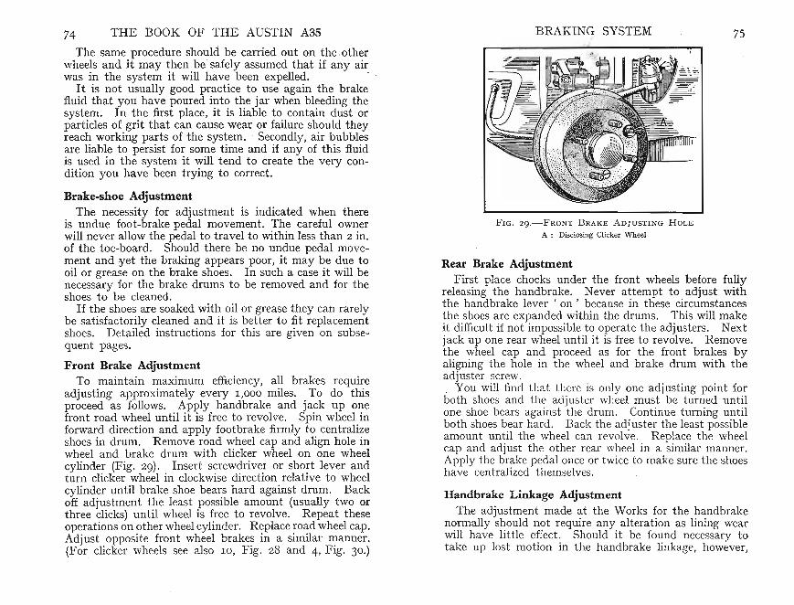
74 THE BOOK OF THE AUSTIN A3S BRAKING SYSTEM 75
The same procedure should be carried out on the .otherwhee~s and it may ~hen . be' safely assumed that if any airwas ill the system It WIll have been expelled. .
It is not usually good practice to use again the brakefluid that you have poured into the jar when bleeding thesystem. In the first place , it is liable to contain dust orparticles of.grit that can cause wear or failur e should theyreach working parts of the system. . Secondly, air bubblesare liable to persist for some time and if any of this fluidis. ,!,sed in the system it ~ill tend to create the very condition you have been trying to correct.
Brake-shoe AdjustmentThe necessity for adjustment is indicated when there
is undue foot-brake pedal movement. The careful ownerwill never allow the pedal to travel to within less than 2 in.of the toe-board. Should there be no undue pedal moven:ent and yet the braking appears poor, it may be due to011 or grease on the brake shoes. In such a case it will benecessary for the brake drums to be removed and for theshoes to be cleaned.
If t~e shoe~ are soaked wit~ o.il or grease they can rarelybe satisfactorily cleaned and It IS better to fit replacementshoes. Detailed instructions for this are given on subsequent page').
Front Brake AdjustmentTo maintain maximum efficiency, all brakes require
adjusting approximately every I ,OOO miles. To do thisproceed as follows. Apply handbrake and jack up onefront road wheel until it is free to revolve. Spin wheel inforward direction and apply footbrake firmly to centralizeshoes in drum. Remove road wheel cap and align hole inwheel and brake drum with clicker wheel on one wheelcylinder (Fig. 29). In sert screwdriver or short lever andturn clicker wheel in clockwise direction relative to wheelcylinder until brake shoe bears hard against drum. Backoff adjustment the least possible amount (usually two orthree clicks) until wheel is free to revolve. Repeat theseoperations on other wheel cylinder . Replace road wheel cap.Adjust opposite front wheel brakes in a similar manner.(For clicker wheels see also I O, Fig. 28 and 4, Fig. 30.)
FIG. 2 9.- F RONT B RAKE A D JUST ING H OL E
A : Disclosing Clicker Wh eel
Rear Brake AdjustmentFir~t place chocks under the front wheels before fully
releasmg the handbrake. Never attempt to adjust withthe handbrake lever ' on ' because in these circumstancesthe shoes are expanded within the drums. This will make~t difficult if not impossible to operat e the adjust ers. NextJack up one rear wheel until it is free to revolve. Removeth.e :vheel cap an? proceed as for the front brakes byaligning the hole m the wheel and brake drum with theadjuster screw.. You will find th at th ere is only one adjusting point forboth shoes and the adjuster wheel must be turned untilone shoe bears again st the drum. Continue turning untilboth shoes bear hard . Back the adjuster the least possibleamount un til the wheel can revolve. Replace the wheelcap and ad just the othe r rear wheel in a similar manner.Apply the brake pedal once or twice to make sure the shoeshave centralized themselves.
Handbrake Linkage AdjustmentThe adjustment made at the Works for the handbrake
normally should not require any alt eration as lining wearwill have little e~ect : Should it be found necessary totake up lost motion ill the handbrake linkage, however,

THE BOOK OF THE AUSTIN A3S BRAKING SYSTEM 77there is adju stment at that point at which the handbrakerod is secured to the sliding link. It is essent ial to providesome free travel in the handbrake before the expander unitexpands the shoes.
The abo ve are the only adjustments that the drivershould normally have t o make, bu t it may be that someadjustment becomes necessary to the handbrake linkage,possibly as a result of cumulative wear or for some otherreason. Generally, your Austin dealer should be allowedto carry out this work , but there may be exceptionalcircumstances when the linkage has to be reset when nodealer is available.
Replacing Brake ShoesIn the course of time, after continued ad justment , it
may be found necessary to replace the brake shoes. Thisis an operation that is well within the capabilities of theaverage owner , provided he follows these instructions carefully. A feature of the Austin design, which will commend it self to the owner-driver keen on carrying out hisown repairs, is that the four brake drums may be removedwithout the necessit y for using a wheel puller.
First jack-up th e car with all four wheels clear of theground . The most convenient way of doing this usuallyis to jack-up one side at a t ime, placing suitable woodenblocks or bricks under the axles in turn. The importantthing is to ensure that when the car is jacked-up it restson a firm base, for you will have to remove all the wheelsin order to work on the brake shoes. It is very disturbingt o have to support the weight of the car on your toes untilsome friends can be found to free you ! In any case, it isnot good for the car to fall off it s supports on to the ground.
Replacing Front Brake ShoesThere are two precautions to observe when either of the
front brake drums is removed. First, do not appl y thehand or foot -brake far , since, as there is no restraininglimit on brake-shoe t ravel, the pist ons may be movedbeyond their normal limited movement thus permittingfluid to escape. Air could enter the system if the pistonsmoved beyond the limits of the cylinders. The brake fluid,
which could be lost und er these conditions, would seriouslyaffect braking efficiency if it reached the brake linings.
Secondly, when the brake shoe is removed take care notto let the piston move out of position in the cylinder. Anelastic band placed arou nd it is a useful makeshift .
E ach brake drum can easily be removed by undoing thecountersunk screw and then drawing it off the wheel studs.If you mark the drum in its position relative to the hubyou will be sur e that when replaced it will run as truly as itdid before you withdrew it . If the brake drum cannot beremoved make sure that the brake adjustment is not tootight. If th is is so, then slackening off each adjuster willfacilitate removal.
It is better to obtain replacement shoes from you r Aust indealer rather than try t o rivet new linings yourself. Thelinings should be firmly bedded and accurat ly ma chinedafte r fixing to suit the brake-drum rael ius. The shoesobtainable through your dealer will be found efficient inthis respect.
Wh en fitting the new shoes, engage them in th e slots ofthe adjuster screw and the opposed-wheel cylinder.
It is advisable to app ly a film of gr ase to the st eadypost s situa ted between brake-she w b and back plate.
The shoe return springs are Jit t d with the hooked endsof the spring to th e outside behind the brake shoe (Fig. 28).
After replacing both brake shoes, refit the brake drum.If marked for positi on, cnsur t hat the marks are in line.In any case take car to wil arefully the flanges on thehub and brake dru m to I r vent grit from throwing thebrake drum slightly out of tune . Secure the drum withthe countersunk screw.
When adjusting the brakes, after fitting replacementshoes, it is advisable to loosen each cylinder anchor bolt.There are two on each brake plate. Each should beslackened off to the extent of about one turn. Then thebrakes should be applied hard so that the cylinders, whichalso form the brake-shoe anchorage, line themseves upwithin the brake drum. The anchor bolts should betightened securely and with the brakes applied in themanner described above. When the bolts have been setin this manner it will be found advisable to check the brakeshoe clearance and adjust if necessary.

THE BOOK OF THE AUSTIN A3S BRAKING SYSTEM 79
14
FIG. 3 0.-RE AR B RAK E A SSEMBLY
I Brake Lining and 2 Shoe. 3 Slotted Adjusting Screw, 4 Clicker Wheel and 5 Spring .6 Pu ll Rod. 7 Rubber Boot. 8 Pin. 9 Back-plate. 10 Abutment Pad. II Spring
Guide. 12 E xpander Unit. 13 P ull-off Spring Short -coil, and 14 Long-coil
Usually it is beneficial to adjust new or recondit ionedsho es to a slightly greater clearance than in the case ofshoes that have alr eady bedded themselves in but laternormal close adjustment can be made.
Replacing Rear Brake ShoesRemove the rear brake drum the mounting of which is
the same as that of the front. Note that the dispositionof the shoes and springs differs slightly. It is best t o dismantle the shoes and springs together by placing-aIargescrewdriver or similar lever against one of the brake-platestuds as a fulcru m (Fig. 30). . .
Pressing the shank against the brake shoe will force itupwards and outwards when each e~d may be disconne~ted
from the expander and ad juster umts. Use only sufficientpr essure to free the brake shoes oth erwise the springs m~y
be strained . With one shoe free, the other may readilybe pu lled away. ..
Wh en pr ising the shoes from their mountings t ake care
not to cause damage to the brake cylinder either by levering on it or allowing a brake shoe to strike it. Shouldthe cylinder bore be dist orted brake-shoe operation couldbe seriously affected. Disconnect the brake spring andtake the shoes t o your Austin agent for re-lining.
Th e brake plate should be carefully cleaned, also thebrake drum, but t ake good care not to leave any greaseor oil on the polished braking sur face ofthe drum. A tipto note when handling brake shoes is to avoid fingering thelinings when the hands are oily and greasy. It is advisableat this stage to unscrew the adjuster fully as any stiffnesscan now be corrected more readily than when everythingis reassembled.
Apply a film of grease to each end of the brake-shoeweb where it ente rs the jaws of the pist on and adjust erunit.
Each pai r of brake shoes can be reassembled with thesprings already fitted. The longer spring fits at the adjust er end and the shorter spring fits at the abu tment padend . Fit each in the correct location installing them sothat the spring is between th e shoe web and the brakeplate. Positi on the screwdriver as for dismantling andgently expand the second shoe until it can be inserted intoplace in the piston and adjust er units.
If it is necessary to alter the linkage refer to the paragraph on page 75. Make sure that both shoes are correctlyentered when a ll is ready for th e brake-drum rep lacement .Check that all locknuts are tight and tha t all split pinsare entered. Then carefully road-t est the car.
ENGINE 81
CHAPTER VII
ENGINE
T H E MODERN CAR ENGINE is so reliable that,provided the radiator is kept filled with water, the
oil level maintained, and the fuel tank replenished fromtime to time, it will function for an indefinit e period withgreat reliability.
It is no long er considered necessary for the driver to bea skilled mechanic capable of coping even with a majorbreakdown on the road as was the case in th e early daysof motoring. It is this reliability inherent in the modernmotor-car that sometimes tempts the owner to neglectnormal routine maintenance. If the best service is to beobtained, however, thi s maintenance remains necessaryeven with the highly efficient pro duct of today.
Although your Austin A35 is capable of running indefinit ely without much attention, neglect will ultimatelyreduce its efficiency causing it s mechanism and appearanceto deteriorate as well as to render a breakdown on theroad more probable. This book is written for the ownerwho takes a pride in his car and who is pr epared to devotea relatively small amount of time to keeping it in first-classrunning order.
As the working of the modern internal combustion engine .is no doubt famili ar to the owner, no lengthy descriptionis justified in these pages. At th e same time, a knowledgeof the various parts and of their functions cannot but be ofa sist ance in helping to obtain the best performance outof your car. Once these principles are clearly understood,III diagnosis of any fault is made easier. To assist further,a fault -finding tabl e is given on page 218. In case of need,r Iercncc to this t able usually provides a clue to th e particula r component th at is causing trouble.
The design of the Austin A35 engine is based on the4-stroke or Otto-cycle principle, as are the majority of carengines to day. A downward movement of the pistonsdraws a correctly proportioned gaseous mixture of petrol
80
and air from the carburettor. This flow enters the cylindersthrough the manifold and inl~t valves.
Dealing with only one cylinder, ':'Ie find that at t~e
bottom of the induction stroke the inlet valve closes, Itsmovements being controlled by the .camshaft. On theupward-compression-stroke both inlet and exhaustvalves are closed. Consequently, the mixture is compressedinto the small space above the piston by the time it hascomplet ed its upward travel.
At the top of the compression stroke an elect ric spark,from current generated through the ignition co~l and tim.edto occur at the correct instant, fires the charge in the cylinder. The highly compressed gaseous mixture expandspowerfully, rapidly forcing the piston downwards <l:ndimparting a power impulse to the cranksh~ft to whichthe piston is connected. At the bottom of this stroke, theexpansive effect being now largely spent, the exhaust valveopens and the piston moves upwards on the exhaust stroke.The burnt gases ' are forced past this valve into a silencerand so out to the air. The piston is now ready to repeatthe complete cycle. . . .
All the four pistons work m .a similar manne~, eachbeing so timed that two power Impulses are applied forevery complete revolution of the crankshaft. . Thus,. aneven and continuous turning effort, or torque, IS obtainedduring the whole time the engine is runmng.
The camshaft is driven at half the crankshaft speed bya duplex roller chain passing over suitably sized sprocketsto give this reduction. A he~ical gear on t~e cams~aft
drives the distributor responsible for producing a hightension spark from the coil at the exact ir;stant and fordelivering it to the plug of the correct cylinder.
Unlike the steam engine, the internal combustion enginedevelops little power at.a low n~mber of r.evo~utions p~r
minute but the power nses considerably WIth mcrease inengine speed. It is obvious, therefore, that all the components must be so timed that the engine m~y revolve atthe requisite speed to develop the l?o.wer required. Shouldthe road gradients or traffic conditions reduce the speedof the engine it will be necessary to change down to a lowergear. Should the engine be called upon to prope~ the carwhilst running at too Iowa number of revolutions per
82 THE BOOK OF THE AUSTIN A35
minute (r.p. m.), severe stresses will be imposed on all theworking surfaces of the engine and t: ansmission leading toexcessive wear. Any attempt to dnve the car too slowlyin any gear will readily be apparent by the harsh andirr egular running resulti-?g ~n. pinking or .knocking. Another symptom is when individual power rmpulses can.befelt inst ead of the normal smooth surge. The hammer- likeblows caused when the engine ' labours' in this manner cando great harm to the working surfaces.
Loss of PowerWhen it is realized that the engine is capable of revolving
at speeds considerably in excess of 4 ,800 r.p.m., <l?Y derangement or even slight misadjustment c~n affect Its perfo.rmance considerably . With loss of efficiency the :evolutlonswill fall and so the engine will not develop sufficient power .If .any falling off in power be noti~ed the reason shoul~ beascertained and the remedy applied as ?oon as possible.
For instance, if for any reason one plug misfires, 2 5 percent. of the available horse-power will be lost and theremaining cylinders will be correspondingly over-loaded.At the same ti me, the engine will no longer r~n smoothly.If the va rious adjustments are known to be m order, andif there is still some reduction in engine power, this maybe due to the need of ' top overhauling ' or as it is morecommonly known decarbonizing. .
In normal use carbo n deposit accumulates on the pistons,va lves, and cylinder head. This carb?n is the pro~uct ofcombustion combined with burnt 011, a proportion ofwhich inevitably passes into the combustion head alb eitin small amounts. The va lves tend to become less gast ight and part icularly so the exhaust. va lves responsiblefor controlling the escape of the burnmg exhaust gases.
This deteriora tion is a gradual process so that generallyth e result ing loss of power will not at once becom~ appare~t.
If th ere is some loss of power usually associated WIthpinking, however, this is genera lly a~ ir:dication t~at decarbonization is necessary although It IS not possible tosay exactly how often this overhaul w.ill be required . . Asa genera l guide , every 10,000 miles IS usually sufficientalt hough some owners with misplaced pride declare theyhave not decarbonized th eir engine for 40,000 or 50,000
ENGINE
miles. The point to bear in mind is that unless steps aretaken to correct slight leakage at the exhaust valves theseva lves may ' burn ' so causing damage to their faces andto their seats in the cylinder block .
To test compression. Hold the accelerator fully openwith the ignition off. Turn the engine by the startinghandle or alternatively by the fan-belt. You should thenfeel a decided resistance at each half turn, sufficient to makethe engine rock back aga inst the pressure until you passtop dead cent re when it will turn partly forward due to airpressure developed moving the piston partly downwards.
Remember to give the engine at least two consecutiveturns otherwise you will not feel if each of the four cylindershas the proper degree of compression. All four compressions should be equal. If one or more has not the samedegree of resist ance it may be due to leaking valves orto tappets with insufficient clearance. Another cause ofcompression loss is leaking piston ring s but th is is notlikely to occur until many thousands of miles have beencovered.
A point to remember is that carbon deposi t will veryslightly rai se the compression ratio by decreas ing thecombustion-head area . In some cases the deposit maybecome red hot an d ignite the mixture before it is fullycompressed . Th is condition, known as pinking, can causeheavy loading on the working parts because the pistonstill moving upward s at the end of it s compression strokereceives the heavy blow of the ignited mixture befor e it isfully at the end of it s stroke. .
The makers advise that va lves of a reconditioned engineshould be grou nd-in and the rocker clear ances should bere-set afte r the first 1 ,0 0 0 - 2 ,0 0 0 miles. The procedure forcarrying out this opera t ion is given in the following pages,t ogether with instructions on how to remove t he carbondeposit.
Decarbonizing the EngineThis opera tion is well within the ability of the intelligent
owner , but suitable prepara tions will redu ce unnecessarywork and assure it s being carried out with a minimum ofinconvenience.
The old tag ' if a job is worth doing at all, it is worth doing

THE BOOK OF THE AUSTIN A3S
well ' applies to the work you are t o carry out on your car.Apart from the unsatisfactory results of a badly performedjob being a continued source of irritation, any oversightor scam ped work may result in a hold-up on the road,possibly miles from a garage.
First , place the car in the garage so that as far as possibleyou have unhampered access t o the engine. It will befound helpful to have an inspection lamp, opera ted eitherfrom the ma ins or connected by a flexible lead to the carbattery. Dark corners can then be clearly illumina tedsince nothing is worse than fumbling in the dark withcomponents the location of which is not clear to you.
Next, place on a convenient bench the va rious tools youare likely to need . Pro cure two or three small boxes inwhich to place the various parts dismantled from theengine so as to pre vent their loss. Although a new par tcan be fitted, once a part is lost there is always the possibility that it may have fallen into the engine where sooneror later it may cause damage. It is a good idea, also, tocover the wings with cloths to prevent their surfaces frombeing scratched.
When decarbonizing, use new gaskets for the cylinderhead and exhaust manifolds obtained in advance fromyour Austin dealer. Apply a film of grease to the cylinderhead gasket when it is replaced or use gold size or one ofthe propriet ary gasket cements marketed for the purpose.You will be well advised to rememb er that the use of acement can make the cylinder head ext remely difficult toremove subsequently . Should it have been used on aprevious occasion, thoroughly clean the surfaces of bothcylinder block and head of all traces of the old cementbefore the new gasket is fitted. You will require someclean rag of some material tha t does not leave fluff sinceparticles of th is may find their way into the engine possiblylead ing to a h ked oil passage.
Valve-grind ing paste will also be needed and can usua llybe bough t in . nv nient tin s containing either a fine or acoarse grad r a ly mixed with oil. It is usually moreeconomical t buy it in th is form rather than attempt tomix a supply Ir m p wder and grease.
A suitabJ 1in is userul to hold paraffin for washing thevarious parts dismant led during the operation. Since you
ENGIN E
will probably also be draining the engine sump at the sametime, another similar tin will be required t o be placed underthe sump to allow the oil to drain into it. This tin shouldbe capable of holding 6 pints.
Raise the bonnet and securely prop it open with thestrut hinged to the radiator cowl. Open the radiator draintap and allow the water to run away, but if you have ananti-freeze solution in the system keep the liquid for reuse. Another tin should be provided for this purpose ifnecessary . Capacity about 81 pints.
With these preparations completed the work can nowproceed .
Dismantling the EngineIn the author's opinion the practice sometimes advised of
warming up the engin e prior to removing the various partsmay do more harm than good . A part that is detachedwhile hot may distort slightly on cooling and afterwardsit may be impossible to obtain the original perfect fitbetween the various flange faces. Therefore, dismantlethe engine cold.
To avoid any possibilit y of short -circuits or of the enginebeing inadvertently turned if the sta rter motor switch isoperated, disconnect the battery by removing the negativeterminal. This will isolate the electrical system.
The air cleaner is held on the carburettor by a clamp bolt .A hose clip secures the hose connecting the air cleanerto the valve cover. Loosen the clamp bolt sufficiently t oallow the cleaner to be removed with the valve cover.
The valve-rocker cover should next be removed. Thisis held by two cap nuts, one at each end on top. Therubber bush and washer fitted on the shank of each capnut should not be lost. Carefully raise the rocker cover ,otherwise the joint washer may be damaged.
Remove the choke cable from the carburettor by loosening the pinch bolt on th e choke lever sufficiently to allowthe cable to be pulled through its locat ion. Remove theaccelerator-to-throttle-lever control rod and disconnectthe petrol pipe by unscrewing the nut securing the filterunion to the float chamber and at the petrol pump. Takecare not to lose the fibre washers fitted on each side of the

86 THE BOOK OF THE AUSTIN A3S ENGINE 87
carburettor-filter banjo union. It will also be necessary todisconnect the distributor-vacuum control-pipe union.
Unscrew the terminals from the four high-tension plugleads and if you are not sure of being abl e to replace themafterwards in their correct order label them I, 2, 3, and4 in order as they are removed, number I being nearest theradiator. Remove the sparking plugs.
Loosen the hose clamp at each end of th e upper waterhose conn ections. It is often found th at this hose adheresfirmly but with care it can usually be removed withoutdamage. If you try to loosen it by pushing a screwdriverbetween the bose and the radiator connection you maysplit the hose. If it appear s firmly fixed it may be anadvantage to cut it , replacing it with a new one whenreassembling the engine.
Undo the hose clips and hoses so that the heater returnpipe can be removed con:pletely as ?therwise it will 1?ein the way when the cylmder head IS removed. A clipfor this is fitt ed a t th e front end of the return pipe and isheld by one of th e yoke-washer nuts. Do not forget todisconnect the other heater pip e at the control valve onthe right-hand side of th e engine above the distributor.
It is best at this stage to remove the manifolds, firstremoving the exhaust pipe at th e manifold joint.
Next , unscrew th e nu ts securing the mJet and exhaus tmanifolds to the cylinder head (Fig. 33). Do not los~ theyoke washers that bridge the lugs of the exhaust and mletmanifold flanges. The manifolds and carbure ttor can thenbe lifted off as a unit.
It is advisable to remove the push rods otherwise theymay be bent when you are trying to lift away the cylinderhead. To facilitate removing them slacke n back therocker-adjust ing screws (3, F ig. 34). This allows the ballend of rocker to be det ached from the push rod and drawnupwards out of position. It will be necessary .to tun~ theengine if it is found that one of the push rods IS holding avalve open.
If you prefer to remove the valve-~ocker gear first thiscan be done. First, disconnect the 011 feed pipe and thenunscrew the nuts secur ing each rocker-shaft bracket . Therocker shaft may then be lift ed off the cylinder head.
Unscrew the nine cylinder-head nuts, the positioning of, ~
FIG. 3 L - ' Y L'I N DE R-H E A D A SSEMBLY
I Valv e Rocke r Cover, 2 w asljcr and 3 Nut Cap. 4 Rocker Shaft. 5 Valve Roc ke rand 6 Spacing Spring . 7 Oil F ilter Ca p. 8 E ngine Slmg Bracket. 9 Cylmd~ Head .IO Carburettor . .II Pet rol Pipe from Pump to Carburettor, I 2 Valve. I 3 Spn ng andI4 Guide. "S Inlet Manifold . I6 E xhaus t Ma nifold and I 7 Was her. I 8 Petrol D ra m p ipe . I9 Cylinder-head J oin t Washer . 20 Thermostat Assemb ly. 2I Wat er Outlet
E lbow
which is shown in Fig. 32. The actual cylinder-head nutsare those below the level of the rocker shaft, those abo ve itbeing used to secure the rocker-shaft brackets to the .cylinder head. Plain washers are fitted beneath the cylinderhead nuts except to th e four adj acent to the rockershaft. These washers ar e of the spring type. Disconn ectthe clips securing the thermostat by-pass hose.
It should now be possible to lift away the cylinder headby easing it upwards parallel with the cylinder block so thatit does not bind on the studs.
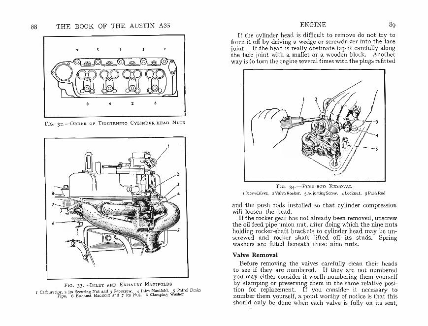
F IG. 3 3 .-INL ET AND EXHAUST MANIF OLDS
I Carbu rettor, 2 its Securing Nut and 3 Set-screw. {Inlet Manifold. 5 Petrol DrainPipe. 6 Exhaust Manifold and 7 its Nut. 8 Clamping Washer
FIG. 3 4 .-P USH- ROD REMO VAL
I Screwdr iver. 2 Valve Rocker . 3 Adj ustingScrew. { Locknut. 5 Push Rod
ENGINE 89
If the cylinder head is difficult to remove do not try toforce it off by driving a wedge or screwdri ver into the facejoint. If the head is really obstinate tap it carefully alongthe face joint with a mall et or a wooden block. Anotherway is to turn the engine several times with th e plugs refitted
and the push rods installed so that cylinder compressionwill loosen th e head.
If the rocker gear has not already been removed, unscrewthe oil feed pipe union nut, after doing which the nine nutsholding rocker-shaft brackets to cylinder head may be un screwed and rocker shaft lifted off its studs. Springwashers are fitted beneath these nine nuts.
Valve RemovalBefore removing the valves carefully clean their heads
to see if they are numbered. If they are not numberedyou may either consider it worth numbering them yourselfby stamping or preserving them in the same relative position for replacement. If you consider it necessary tonumber them yourself, a point worthy of notice is that thisshou ld only be done when each valve is fully on its seat ,
7
62..8
9
THE BOOK OF THE AUSTIN A3S
FIG. 32.-0RDER OF TIGHTENING CYLI NDER-H E AD NUTS
88

90 THE BOOK OF THE AUSTIN A3S
otherwise the stem may be bent and the valve will leaksubsequently. A convenient way of preserving theirorder is to drill eight holes in a board, the holes being 'ofsuch a size that only the valve st ems may pass through.
F IG. 3 5 .- U SI N G T OOL T O C OM P RESS V ALVE S P RI N G
They may then be kept in the same order as when in the~~. ."
The next operation, valve remo val, IS greatly facilitatedby using a valve-spring compression to ol (Fig. 35). Thereare several va riat ions of this tool but th e essential purposeis that whilst one end rests on the head of the valve, theother fits on to the valv e cotter cup. By suitable meansthe tool is then actuated to compress th e valve spring andcotter cup . so allowing ' the two split cotters at th e valvestem end to be freed from th eir location in th e groove aroundthe valve-stem end.
You will see that a spring circlip is fitted around thetwo cotters and must be detached before they in turn canbe withdrawn.
An alternative method of rem oving the valve spring isto place a suitable block of wood inside the combusti onhead so that it rest s on the valve to be removed. The
ENGI NE 91
wood should not be appreciably thicker than the depth ofthe combusti on space within th e head. By placing thiswood as direct ed, and with the cylinder head flat on theben ch , all that is th en necessary is to press down firmlyon the cotter cup, removing the cot ters as described above.The block of wood is to preve nt the valve moving downwards when the pr essure is applied. Take care not toallow the spring and cotter cup to jump out of positionbefore you are ready , otherwise they may take some finding!
Be methodical over this valve removal. Immediatelyyou have released th e two cotters and circlips place themin the box you are using for part s and repeat this wit hthe other seven va lves . This will ensure that you haveactually retained all the par ts.
E ach valve cotter cup has an upper and a lower partbet ween which is an oil seal. This seal is th ere to preventoil working downwards past the cot ters and reachin g th ecombusti on chambers by way of the valve guides. Preferabl y, renew these oil seals when reassembl ing.
By dividin g the va lve cotter cup upper and lower partsthe rubber seal will be disclosed and can then be removed.Carefully clean away any traces of the rubber should thishave adhered to the met al surfaces.
Carbon RemovalClean away all carbon from inside th e combust ion heads
and valve ports . It is as well to take care not to scratchthe va lve seats in the head for it is essent ial that theyshould form a perfect seal.
When the cylinder head has been thoroughly decarbonizedit is a good plan to remove th e carbon deposit also fromthe pistons and th e following procedure should be adopted .
Since carbon is an abrasive and usually breaks away insmall particles it is best to work on one piston at a time.Owing to the crankshaft construc t ion two pistons will beup whilst two are down. Stuff rag into the two cylinderbor es in which th e pistons are at th e bottom of their stroketo prevent carbon chips entering them. A good tip is tosmear grease around the edge of th e piston at the junctionwith the cylinder bore. This will pr event carbon enteringat this point.
Take great care not to scratch the piston heads since
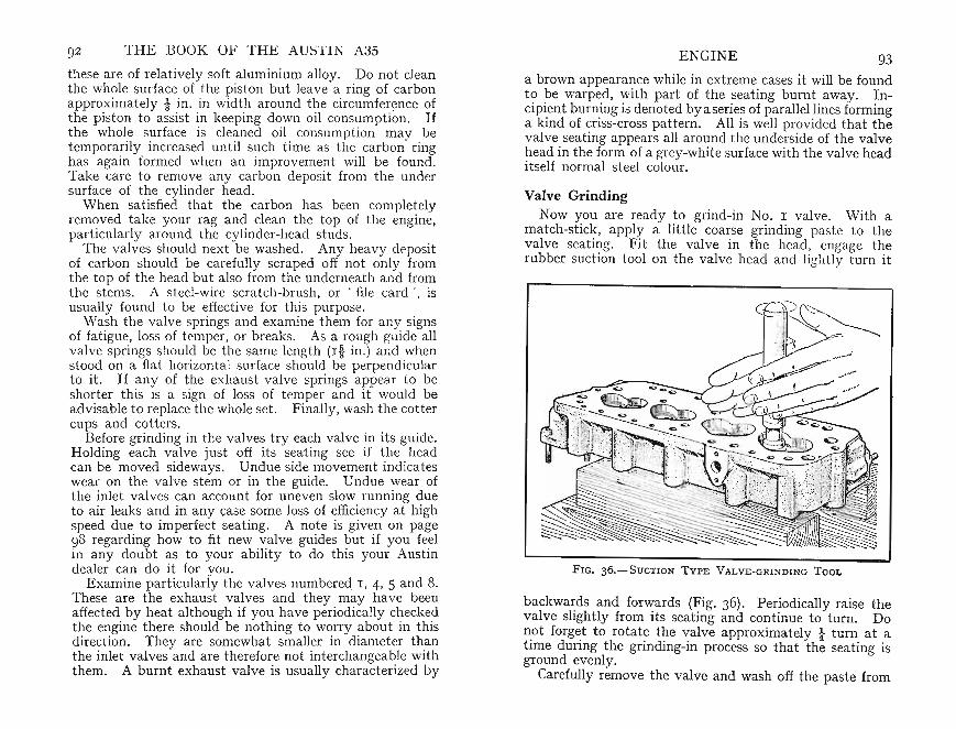
Valve GrindingNow you are read y to grind-in No. I valve. With a
match-stick, apply a little coarse grindin g paste to thevalve seating. Fit the valve in the head , engage therubber suction too l on th e valve head an d ligh tly tu rn it
backwards and forwards (Fig. 36). Periodically raise thevalve slight ly from its seating and continue to tum. Donot forget to rotate the valve approximately t turn at atime during the grinding-in process so that the seating isground evenly.
Carefully remove the valve and wash off the paste from
a brown appearance while in extreme cases it will be foundto be warped, with part of the sea t ing burnt away. Incipient burning is denoted bya series of parallel lines forminga kind of criss-cross pattern. All is well provided that thevalve sea ting appears all around the underside of the valvehead in the form of a grey-white surface with the valve headitself norm al steel colour.
93ENGINE
FIG. 36.-SuCTION TYPE VALVE-GRI NDING TOOL
92 THE BOOK OF THE A USTIN A3S
these are of relatively soft aluminium alloy . Do not cleanthe whole sur face of the pisto n but leave a ring of carbonapproximately! in. in width aro und the circumference ofthe pist on to assist in keepin g down oil consumpti on. Ifthe whole surface is cleaned oil consumption may betemporarily increased until such time as th e carbon ringhas aga in formed when an improvement will be found.Take care to remov e any carbon deposit from the undersurface of the cylinder head.
When satisfied that the carbon has been completelyremov ed tak e your rag and clean the top of th e engine,particularly around the cylinder-head studs. .
The valves should next be washed . Any heavy deposItof carbon should be carefully scraped off not only fromthe top of the head but also from the un dernea th and fromth e stems . A steel-wire scra tch-brush, or . file car d ', isusually foun d to be effective for th .is purpose. .
Wash th e valve springs and examme them for an)' signsof fatigue, loss of temper, or breaks. As a r<?ugh guide allvalve spr ings should be th e same length (I t m.) an d .whenstood on a flat horizontal surface should be perpendicularto it. If any of the exhaust valve springs appear to beshorter this is a sign of loss of temper and it would beadvisab le to replace th e whole set . Finally, wash the cot tercups and cotters. . . .
Before grinding in the valve~ try ea~h valve ~n ItS guide.Holding each va lve just off ItS s~atmg see If ~he . headcan be moved sideways. Undue Side movement indi cateswear on th e valve stem or in the guide. Und ue wear ofthe inlet valves can account for un even slow running dueto air leaks and in any case some loss of efficiency at highspeed du e to imperfect seati ng. A no.te is give.n on page98 regarding how to fit new .v:alv e guides ~)Ut If you fe.elin any doubt as to your ability to do this your Austindealer can do it for you.
Examine particularly th e valves numbered I, 4, 5 and 8.These are the exhaust valves and they may have beenaffected by heat although if you ha ve periodically c~ecke.d
the engine there should be nothing to w~rry ~bout m thisdirection. They are somewhat smaller ill diameter th.anthe inlet valves and are th erefore not interchangeable WIththem. A burnt exhaust valve is usually characterized by
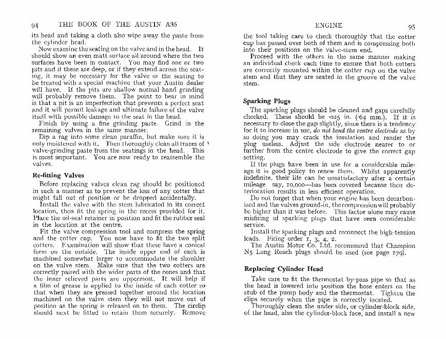
94 THE BOOK OF THE AUSTIN A3S ENGINE 95its head and taking a cloth also wipe away the paste fromthe cylinder head.
Now examine the seating on the valve and in the head. Itshould show an even matt surface all around where th e twosurfaces have been in contact . You may find one or twopits and if th ese are deep, or if they extend across the seat ing; it may be necessary for the valve or the seating tobe treat ed with a special machine t ha t your Aust in dealerwill have. If the pits are shallow normal hand grindingwill probably remove them . The point to bear in mindis tha t a pit is an imperfection that prevents a perfect seatand it will permit leakage and ultimate failure of the valveitself with possible damage to the seat in th e head.
Finish by using a fine grinding paste. Grind in theremaining va lves in the same mann er.
Dip a rag into some clean para ffin , but make sure it isonly moistened with it. Then thoroughly clean all traces of \valve-grinding past e from the seati ngs in the head . . Thisis most imp ortan t. You are now ready to reassemble theva lves.
Re-fitting ValvesBefore replacing valves clean rag should be positioned
in such a manner as to prevent the loss of any cotter thatmight fall out of position or be dropped accidentally.
In stall t he valve with the stem lubricated in it s correctlocati on, then fit th e spring in th e recess provided for it.Place the oil-seal retainer in position and fit the rubber sealin the location at th e centre.
Fit th e va lve compression t ool and compress the springand the cotter cup. You now have to fit the two splitcotters. Examination will show th at these have a conicalform on th e outside. The inside upper end of each ismachined somewhat larger to accommoda te the shoulderon the va lve stem. Make sure that the two cotters arecorrect ly paired with th e wider parts of the cones and thatth e inn er relieved parts are upperm ost. It will help ifa film of grease is applied to the inside of each cotter ~o
th at when they are pressed togeth er around th e loca tionmachined on the . val ve stem they will not move out ofposition as the spr ing is released on to th em. The circlipshould next be fitted to ret ain th em securely. Remove
the tool taking care to check thoroughly that th e cottercup has passed over both of th em and is compressing bothinto th eir 'positions on the valve-stem end.
Proceed with the others in th e same manner makin gan individual check each time to ensure that both cottersare correct ly mounted within the cotter cup on the va lvestem and th at they ar e seated in th e groove of th e valvest em.
Sparking PlugsThe sparki ng plugs should be cleaned and gaps carefully
checked. These should be '025 in. (,64 mm.). If it isnecessary to close the gap slightly, since there is a tendencyfor it to increase in use, do not bend the centre electrode as byso doin g you may crack the insulation and render theplug useless. Adjust the side elect rode nearer to orfur ther from the centre electrode to give the correct gapsetting.
If th e plugs have been in use for a considerable mileage it is good policy to renew them. Whil st apparentlyindefinit e, their life can be unsatisfactory after a certainmileage- say, ro .ooo-s-has been covered because their deterioration results in less efficient oper ation.
Do not forget that when your engine has been decarbonized and th e valves ground-in, thecompression will probablybe higher than it was before. This factor alone may causemis~ring of sparking plugs that have seen considerableservice.
In stall the sparki ng plugs and reconnect the high-tensionleads. Firing order 1, 3, 4, 2.
The Aust in Motor Co. Ltd. recommend that ChampionN5 Long Reach plugs should be used (see page 179).
Replacing Cylinder Head
Take care to fit the thermostat by-pass pipe so th at asthe head is lowered into position the hose enters on thestub of the pump body and the thermostat . Tighten theclips securely when the pipe is correctly located .
Thoroughly clean the under side, or cylinder-block side,of the head, also the cylinder-block face, and install a new
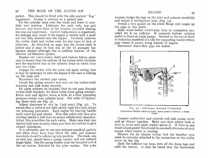
F IG. 3 7.-ADJUSTING R OCK E R C LEARANCE
I Screwdriver Bladein Adju stin g Screw. Arrow points to Locknut. 2 FeelerGauge
washers bridge the lugs on the inlet and exhaus t manifoldsand. ensure a sa t isfac tory joint (Fig. 33).
Install a new gas ket on the lower flange and couple upthe pipe at this point.
Refit wat er-heater ret urn-pipe hose to connection provided for it on radi ator. It connects bottom radi atoroutlet to block at wa ter pump. Secured to the nut at frontof induction manifold is a clip for supporting heater returnpipe where it passes along outside of engine.
Reconnect wate r-flow pipe for heater .
Connect carburettor an d controls and refit rocker coverand air clean er together. Make sure that rubber bush isnext to cover with plain washer ab ove it. If there is anydoubt about gasket this should be renewed otherwise oil mayescape when engine is running.
Replace the air cleaner noting that the breather pipemust be correctly attached to the connection on the rockercover by the clip.
Refit the radiator top hose, turn off the drain taps and. .refill the syst em. It may be found that the thermostat
97E NGINE96 THE BOOK OF THE AUSTIN A3S
gasket. This should be fitted with the side marked ' Top'uppermost. Grease is advised as a gasket seal. .
Fit the cylinder head over the studs and lower It carefully into position. Lubricate the push ro~s, top . ~ndbottom and insert them in the location -provided makingthe cup' end upp ermost. Correct replacement is important,for damage may result if the engine is t urned with a p~sh
rod not fully ente red into the tappet . Carefully exammethe rocker sha ft and rocker ends for any signs of lack oflubricant. As describ ed on page 202 , t he rocker shaft ishollow and it may be that one of the oil passages hasbecome choked although this is unlikely because of theefficient oil-filtr ation system.
Replace the valve-rocker shaft and rockers t ak ing greatcare to ensure that the bottom of the rocker-shaft bracket san d the machined face of the cylinder head on which theyseat are clean.
E ngage the rocker wit h the pus~ ro.d again n~ting t~at
it may be necessary to turn the engine If the cam IS holdingup the push rod.
Reconnect the oil-feed pipe union.Install the spring washers and nuts on the rocker-shaft
brackets and pull down securely.Fit plain washers on brackets that do not pass through
rocker-shaft brackets, for these latter have spring washers .Enter nuts and tighten down a little at a time, sp~eadingpressure evenly over cylinder head. For order of tighten-ing these nuts see Fig. 32. . .
Adjust clearance to '012 in. ('305 mm.) (FIg. 37) . Toensure that a valve is not held partly open by a cam, adopt .the followin g procedure. Turn engi~le b:f starting han?leuntil valve has just closed. Note this ~omt and then grvestarting handle a half turn to ensure satisfactory clearance.Ado pt this procedure for each valve. Make sure that ~outi ghten lock nuts securely when you have set rockers to grvecorre ct clearances.
It is advisable also to use new exhaust-manifold gasketsan d when these have been fitted the inlet and exhaustmanifolds should be offered up into position. . The st uds, oneat each end, should have a spring washer and nut enteredfinger-tight. Slip the spring washer over the thread ed end ofthe set screws . followed by the yoke washer. The yoke
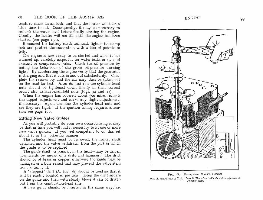
tends to cause an air lock, and that the heater will take alittle time to fill. Consequently, it may be necessary torecheck the water level before finally starting the engine .Usually, the heater will not fill until the engine has beenstarted (see page 133).
Reconnect the battery earth terminal, tighten its clampbolt and protect the connection with a film of petroleumjelly .
The engine is now ready to be started and when it haswarmed up, carefully inspect it for water leaks or signs ofexhaust or compression leaks. Check the oil pressure bynoting the behaviour ' of the green oil-pressure warninglight . By accelerating the engine verify that the generatoris charging and that it cuts in and out satisfactorily. Complete the reassembly and the car may then be taken outon the road for test. After its first run the cylinder-headnuts should be tightened down finally in their correctorder, also exhaust -manifold nuts (Figs. 32 and 33).
When the engine has covered about 500 miles recheckthe tappet adjustm ent and make any slight adjustmentsif necessary. Again examine th e cylinder-head nuts andsee they are tight. If the ignition timing requires alteration see page 176.
Fitting New Valve GuidesAs you will probably do your own decarbonizing it may
be that in time you will find it nece;;sary to fit oneor morenew valve guides. If you feel competent to do this setabout it in the following man ner: ' ,
The cylinder head must be removed, the rocker shaftdetached and the valve withdrawn from the port in whichthe guide is to be replaced.
The guide itself-a press fit in the head-may be drivendownwards by means of a drift and hammer. The driftshould be of brass or copper, otherwise the guide may bedamaged or a burr raised that may prevent the valve stemfrom entering it.
A ' stepped ' drift (A, Fig. 38) should be used so that itwill be readily located in position. Keep the drift squareon the guide and then with steady blows it can be drivenout from the combustion-head side.
A new guide should be inserted in the same way, i.e.
98 THE BOOK OF THE AUSTIN A35ENGINE
F IG. 3 8 .-RE M OVING VALVE GUIDE
Inset A. Shows form of Tool. In set B. The val ve Guide should be H in. aboveCylinder Head
99
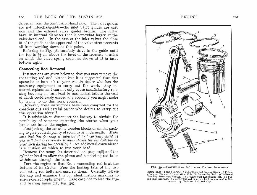
100 THE BOOK OF THE AUSTI N A3S ENGINE 101
driven in from the combustio n-head side. The valve guides.are not mterchangeable- the inlet valve guides are castiron and the exhaust valve guides bronze. The latterhave an intern al diameter that is somewhat larger at thevalve-head end. In the case of the inlet valves the closefit of the guide at the upper end of the valve st em preventsoil from working down at this point.
Referring to Fig. 38, carefully drive in the guide untilthe top is it in. above the level of the recessed locationon which the valve spri ng seats, as shown at B in insetbottom right.
Connecting Rod RemovalInstruct ions are given below so that you may remove the
connecting rod and pistons but it is suggested that thisoperation is best left to your Austin dealer who has thenecessary equipm ent to carry out the work. Any incorrect replacement can not only cause unsatisfactory running but may in turn lead to mechanical failure the costof which could easily exceed any economy you might makeby trying to do this work yourself.
However, these instructions have been compiled for theconscientious and careful owner who desires to carry outthis operat ion himself.
It is advisable to disconnect the battery to obviate thepossibility of someone operating the starter when yourhands are inside the engine !
First jack up the car using wooden blocks or similar packing to give yourself plent y of room to lie underneath. Makesure that this packing is substantial and carefully fitted as'you will find it extremely painful should the car collapse onyour chest during the operation! An additional convenienceis a cushion on which to rest your head .
Remove the sump (as described on page 198) and thecylinder head to allow the piston and connecting rod to bewithdrawn through the bore .
Turn the engine so that NO.1 connecting rod is at thebottom of its stroke. Free the locking t abs of the twoconn ecting-rod bolts and unscrew them. Carefully releasethe cap and examine this for identificat ion markings toensure correct replacement. Take care not to lose the bigend bearing liners (II , Fig. 39).
FIG. 39.-CON N ECTING ROD AND PISTON ASSE MBLY
Pis ton Rings : 1 an d 3 Parallel, 2 and 4 Taper and Scraper Rings. 5 Pis ton.7 Gudgeon Pin and 6 Lubrica tion Hole. 8 Connecting Rod . 9 Li ttle-endClamping Screw and Washer. 10 CYlinder-wall Lubricating J et . II Bigend Shell Bearings, 12 Connec ting -rod Cap. 13 Lock-wash er and 14 Set-
screws. I S Mark on Rod an d Cap

I02 THE BOOK OF THE AUSTIN A3S ENGINE I03
Push the connecting rod and piston upwards throughthe cylinder bore. If there is any accumulation of carbonat th e top of the bore remove it. .
You are now able to examine the piston rings and connectin g-rod bearings. These latter are of the non-adjustable shell type. The rings may be replaced if necessary.It will be found of help if three pieces of metal are used to
FIG. 4 o .- M E TAL S TRI PS US E D AS SLIDES FOR PIST ON RIN GS
act as ' skids ' when removing the rings to avoid breakingthem. Insert these equally around the circumference andexpand the rings gradually so that the ' skids' pass between the piston and the inside face of the ring (Fig. 40).
Make sur e that rings are not too tight in their grooves.Test with a feeler gauge. There should be not less than-oorj in. nor more than '0035 in. ('0381 to '0889 mm.)ver ticle movement (Fig. 41). If the rings conform to thesedimensions insert them in the cylinder bore approximately
F IG. 4I.- CHECK I N G S IDE C L E ARA NCE OF A PISTON I N ITS G ROOV E
one-third of the way down and truly square. Pushing thepist.o~ into the bore will position the ring. The gaps in thisposition should be between '006 and ' OIl in. ('1524 to'2794 mm.). If the gap is less than '006 in . it will be necessary to file one end of the ring very accurately with a finefile until the requisite dimension is obtained. Carefullyrem ove any burrs and the ring is ready for replacement onthe piston. .
Gudgeon Pin. Any wear at the gudg eon pm may be due to the cumula-
, t ive effect of movement between piston and pin. To remove gudgeon pin unscrew and remove clamp bolt withspring washer (9, Fig. 39) to allow pin to be pressed out ofconnecting rod in which it is a push fit.
Gudgeon-pin replacem ent is effected by pressing the pinthrough the piston boss and aligning it with the little end

104 THE BOOK OF THE AUSTIN A35
of the connecting rod so that the cut-away slot in the pinregisters with the bolt hole in the little end. Refit theclamp bolt and spring washer, and tighten up securely.
If you are fitting new connecting-rod bearings note thatthese have a small locating tongue that registers with asuitably cut location in the connecting rod and cap. Thesemust be scrupulously clean on both surfaces and the oilholes (6 and 10, Fig. 39) mu st be unobst ructed.
~lmW\~~i , !.. . . . . . l ._ •• ~
~jtiii-:~;~iUil~·r.: :. .. . .!.•••• .:. .. ... :
FIG. 4 2 .- POSITION OF OFF-SETS .AND CORRECT ORDER OFASSEM BLY OF C ONNECTING RODS
When refitting piston carefully oil the pistons ringsand piston skirt as well as the gudgeon pins.
Note that the oil holes (ro, Fig. 39) must always face away fromcamshaft side of engine.
Ensure that the holes line up with corresponding holesin shell bearings to allow free passage of oil.
Each connecting rod is numbered and each half is alsonumbered. The numbers must be towards the camshaft.These numbers appear on split sides of connecting rod smallends.
ENGINE lOS
Correct order of assembly of connecting rods is shownin Fig. 42. On all pistons split skirt must face enginecamshaft;
Position each piston-ring gap one-quarter of a turn fromthe next and the piston is ready for insertion in the cylinderbore. Piston-ring clamps are available through the variousaccessory factors and may be fitted over the piston ringsto facilitate entering them into the cylinder. If you donot possess such a tool take great care to compress eachring in turn so that it enters the bore properly. There is at endency for the rings to overlap the piston and they breakeasily.
With pistons correctly insert ed apply a film of oilto the big-end bear ings. Couple them up to the crankpinmaking sure the cap is fitte d in its original location. Install a new locking tab beneath the head of each bolt butbefore finally locking the head of the bolt with the tabturn the engine. If the engine is sti ff and if this stiffnesscan be removed by loosening these big-end bolts , then thereis some incorrect assembly and you must not proceed further until the cause has been found.
Crankshaft main bear ings are of similar type to thebig-end bearings and although it is possible to removethem if you consider these bearings need attent ion youwould be well advised to leave this to your Austin dealer.

CARBURETIOR 1°7
2
FIG. 43 ,- Z ENITH T YPE 26 VM E CARBURETTOR
I Fuel Inlet. 2 Choke Con trol Spindle Arm . 3 Air Mixtur e.4 Choke Inter-connection to Throttle. 5 Vacuum TimingContr~l. 6 Th rot tle St op Screw. 7 ' Con trol Spind le Arm ,8 Mam J et Cover, 9 Compressing J et Cover . 10 Float
Chamb er Retaining Bolt
throttle. . The slow-runnin~ jet , in operat ion only when~h~ot~le IS n~arly closed, IS responsible when engine is
ticki ng-over . . As. speed increases and main jet takesover , slow-runrung Jet cut s out automatically.
As has been explained already, when starting from cold,choke on dash board is pulled so as to close air intake.!his act ion .causes throttle to open slightly by means ofmterconnectIOn. rod (4, Fig .. 44). Most of the depressioncaused by rotation of engme ISconcent ra ted on progressionslow-rl;Innin&", and emulsi?n block outlets (I, 2, and 6):Very httle air enters at this stage and so mixture is rich asis desirable when st arting from 'cold.Whe~ the.engine fires, a heavier depression is created on
the engme SIde of strangler flap (3). As this is held closedonly by autoI?atic sprin~ t ension it now is caused to opena~d close rapidly by engrne pulsations. In consequence, amIxh:re weaker and . of greater volume is provided, thusensun ng a good engrne speed until normal working temperature is attained.
6
7
= .L.-_- 5
89
How the Zeni th Operates
The Zenith carburettor (Model No. 26 VME) (Fig. 43), asfitted to the A35, is of the down-draught type. It isso calledbecause air enters at the top, travels vertically downwardsthrough the choke , taking with it into the induction manifold a correct ly proportioned quan ti ty of petrol. Apartfrom.being an efficient type of carburettor it automa ticallyprovides a correctly propo rtioned mixture through allranges of throttle openings.
Fu~l drawn from th e tank by th e pump (Chapter IX) issupphed to the carburettor float chamber. This containsa float and needle-valve mechanism to ensure a constantpetrol level irrespective of the varying proportions of petrolthat may be used by the engine according to the part icularthrottle position.
The carbure ttor also contains main jet , compensatingjet and slow-running jet . Once engine speed has risensufficiently, main , compensating and slow-running jetssupply the necessary fuel in correct proportions up to full
106
CHAPTER VIII
CARBURETTOR
I F T~E AVERAGE OWNER has cause to complain of, e.rratIc or unsat isfactory running, without further ado orlog~cal reason he usually blames it on the carbure ttor.ThIS may be due in part to the fact that as it is relat ivelyeasy to ad just, unskilled alt erations are often the cause ofbad performance: If the complaint is analysed , however ,th~ carburettor IS rarely to blame. 'Fiddling' with theadJustn:ents can ups~t ~oth igni~ion an d valve setting.
Provided that periodic attention as described in thischapter is car ried out, unsat isfactory running is generallytraceable to some other cause than the carburettor. Itis an accurate metering instrument designed by expertsand any attempt to improve its efficiency usually resultsonly in loss of performance.

FIG. 44.- S E CTION OF 26VME C ARBURE TTO R
I Progression Outlet. 2 Slow-running O'!tl et. 3 Stran gler Flap. 4 Interconn ectionRod. 5 Air Regula ting Screw. 6 Em ulsion Block Outl et Nozzle. 7 E mulsion Tu be8 Tbrottle Stop Screw. 9 Slow-ru nning J et. 10 Needle Seat ing. II Floa t. 1 2 Well.13 Compensating J et . 14 Tube and 15 its J et . 16 Main J et an d 17 T ube
Choke may be released gradually un t il it can be returnedt o its closed position, when strangler flap will be fully open.
For normal operation when throttle is closed and engineis ' ticking-over' .petrol/air mixt ure is supplied from slowrunning jet (9). Depression will be concentrated onslow-running outlet (2) and in turn will be directed toslow-running jet (9) where there is a fall in depressioncontrolled by adjustment of air-regulating screw (5).
Petrol will be drawn from well beneath slow-running jet(12). At thro ttle edge is a further outle t (I ) where depression will be concentrate d. When throttle is opened fromidling position a progressive get-away from slow-runningis a sured. On throttle being opened fur ther, depressionwill be concentrat ed on nozzle (6) of emulsion block proj ecting into narrowest part of choke tube. The result is thatpetrol can be drawn from passages (7 and 13), because aready reserve of petrol must be available for instantacceleration.
The event ual source of petrol supply is through main andcompensating jets (15 and 16). When petrol in well (12)has been consumed, and as top of well is open to atmosphere,
108 THE BOOK OF THE AUSTIN A3S CARBURETTOR 109
jet (IS) becomes air-bled. Petrol issuing from main jet (16)will meet emulsified petrol from compensa ting jet in acommon channel (7) thus tending to break-up petrol frommain jet. Supply from both sources will then be drawninto choke tube from emulsion block nozzle.
As soon as petrol in float chamb er sinks below .a predetermined level, float will fall and permit needle to dropfrom its seating (10) and allow petrol to pass through seatinginto chamber.
AdjustmentsSlow-running adjustment, when engine is out of gear
sometimes known as 'idling '- is obtained by means oft hrottle-stop screw (6, Fig. 43) and air-regulating screw (3)·The former dete rmines degree of slow-running and enablesthrottle position for idling to be adjusted. To increaseslow-running speed this control must be turned clockwise.·If turned in opposite direction, it will give slower' ti ckover ', If engine is inclined to 'hunt ' when runningslowly, mixture is too rich and must be weakened by turningair-regulat ing screw in an anti-clockwise direction . Thiswill cause a reduced depression on slow-running jet resultingin a reduced output.
If weakness at slow-running speeds is suspecte d, then airad justment screw should be turned in a clockwise direction.This will reduce air leak at screw to give a greater depressionon slow-running jet.
If the carburettor is old, it is impossible to have goodslow-running. It must be remembered that there arefactors other than carburettor that influence slow-running.These include joints that are not air-tight,worn valveguides,valves not seating, ignition over-advanced, and incorrectsetting of sparking plug points. Once carburettor has beencorrectly adjusted, however, no attention should be necessary for many thousands of miles.
It may be here mentioned that slightly weaker carburettor settings may be found necessary on cars used inhot climates. Alternatively, slightly richer settings (largerjets) may be used in cold climates.

IIO THE BOOK OF THE AUSTIN A35 CARBURETTOR III
DismantlingNo working parts of the Zenith carburettor are subject to
derangement by wear. All.fuel is filtered, thus eliminatingany possible source of trouble. In addition, air is clean edby having passed through air filter.
Grit or water may enter the passages should filters orbowl not have been cleaned and drained often enough.
Water in pet rol can give trouble unexpectedly becauseit will not pass through the small orifices and so, beingstarved of petrol, the engine misfires or stops.
Somet imes, therefore, it may be necessary to dismant le orclean the carburettor but the design is such that those partsrequiring attention are readily accessible. Before disma ntling, ensure that your hands and bench are thoroughlyclean . If possible dismantle over a metal tray or somesimilar clear surface so that , if you are unfortu nate enoughto drop any small par t , it may be retrieved.
Float chamber (27, Fig . 45) should be disconnecte d byunscrewing secur ing bolts (3) and with float (33) removed toa safe place. Remove main and compensating jet plugs(24 and 26), both of which are located on underside of floatchamber. Main compensa ting jets may be unscrewed byusing squared end of one of the float chamber retainingbolts.
Slow-running jet (36 inset) and screw over capacity well(37) may also be removed from float chamber.
Next, unscrew the five set screws (I 8) securing emulsionblock (I g) to float chamb er, t aking care not to damage .joint washer (20).
Hold carburettor firmly in one hand and with the help ofa suitable spanner remove needle seat ing (2I) and washer (22).
Remove strangler flap (2) by unscrewing the two screws(I), allowing strangler spindle (30) to be withdrawn aft erunhooking st rangler spring (3I) .
The strangler flap is bevelled along its two rounded edges,consequently special care should be taken before removingit. It can be fitt ed correctly only one way . Correctposit ion of stra ngler spr ing should also be noted withreference to strangler lever (28).
The inter-connection rod (8) should now be disconnect edfrom its upper end.
FI G. 45.-ExPLOD ED VIEW OF 26 VME C AR BURE TTO R
I Screws Fixing and 2 Stran gler F lap. 3 Screws Bowl to Barre l. 4 Choke Tu be. 5Carb uretto r Body. 6 Air Regulating Screw. 7 Screw Fitting Choke Tu be. 8 In ter connect ion Rod. 9 Float Lever. 1 0 Throttle Lever and II Fixing Nut . 1 2 SprmgW asher. 13 Throttle Spindle. 14 Throttle F ixing Screws. 15 Throttle. 16 StopScrew Spri ng. 17 Stop Screw. 18 Set Screws Fixing. 19 Emulsion Block and 20Gas ket. 21 Needle Sea tin g and 22 Washer . 24 Compensating J et and 23 Wash er.25 Main J et Washer and 26 J et. 27 Fl oa t Chamber. 28 Strang ler Lever . 29 Retain ingClip for Strangler Lever. 30 Strangler Spindle and 31 Spring. 32 Spr ing for StranglerLever. 33 Float. 34 Gasket (bowl to barrel) . 35 Air Release Tube. 36 Slow-running
J et . 37 Screw over Capacity Well
A clip (2g) holds strangler lever in position. Undo thisand strangler lever will slip off along with its spring (32),the correct assembled position of which should be not ed.
With throttle (IS) closed, also note relative positions offloating lever (g) and interconnecting rod assembly andthrottle lever (IO). Also note the way in which the bevellededges of the throttle fit in the bore of carbure ttor body.Alternatively observe the position of dimples on the throttle.
Unscrew the two throttle fixing screws (I4) and withdrawthrottle. The spindle (I3) can then be taken out with

lIZ THE BOOK OF THE AUSTIN A35
floating lever, inter-connect ing rod assembly and throttlelever , leaving spring washer (re) and nut (II) in position.
Take out thr?ttle stoJ? screw (r7) and its spring (r6).Also remove air-regulating screw (6) together with itsspring. Wh en det ached screw (7) will allow choke tube (4)to be taken out.
Reass emblyReassembling the carburettor is straightforward if the
dismantling process is followed in reverse. If old ordamaged, change joint washer (34) between float chamberand carburettor body. Ensure that float is replaced withside marked 'TOP' uppermost .
It is best to leave emulsion block in position, for it isunlikely there will be cause to remove this at any time.
Cleaning JetsFlush chamber with petrol and clean jets by blowin g
through them- either with a tyre pump or with the mouth- in reverse direct ion to fuel flow. Do not use wire forprobing them or you may enlarge the carefully calibra tedorifices or cause a burr that will partially block them.
Having t horoughly cleaned float chamber and passages,replace jets. Before doing so, however, ensure that thefibre washers are correctly positioned and in good condit ion.Re-install float wit h the mark ' top' uppermost.
Before positioning carburettor, operate hand primer leveron pump to ascertai n that petrol passes freely throughneedle valve . If it does not, see' Petrol Supply Failure 'on page 1ZO.
Incorrect MixtureFor all positions of the throttle above that for idling the
carburettor setting is predetermined by the sizes of themain jet, compensator jet and choke tube. Own ers sometimes try to fit smaller jets in an attempt to obtain betterfuel consumption but by unduly weakening the mixturesuch experiments give rise to overheating often causingthe exhaust valves to burn. In addition, loss of power isexperienced necessitating a wider throttle opening andusually an increased fuel consumption. Standard sizes:
CARBURETTOR II3
Choke tube: 2Z mm, with third bar. Main jet: 80.Compensating jeti: 57. Slow-running jet: 50. Incidentally, all jet sizes are clearly marked on the jets-thehigher the number, the larger the jet.
An incorrect mixture is either too weak or too rich. Iftoo weak the engine runs erratically when idling and tendsto stop suddenly. 'Spitting back' through the carburettor is a symptom of a restricted jet, weak mixture, faultyignition, or sticking valves.
If the mixture is unduly rich the engine after a whilewill tend to choke itself to a stop. On accelerating it willhesit ate before clearing itself and again running evenly.
Lack of acceleration may be due to faulty slow-runningadjustment , retarded ignition or heavy carbon deposits ·incylinder head. Other causes are faulty fuel supply, dirt incarburettor, par ti ally blocked jets, engine not correctlytimed, indifferent compression, sticking or badly-seat edvalves.
High fuel consumption may be due to any one, or a combination, of the following: Over-rich mixture. Dirty aircleaner. Excessive vibrat ion on enginemountings. Flooding carburettor. Incorrect jets.' Leaks in fuel supply line.Strangler-flap partially closed.
Punctured FloatA punctured float is rare. It can be verified by shaking
the float, when the petrol inside can be heard splashingabout. It is better to replace a leaky float for any attemptto solder the leak will increase the weight thus causing thelevel to be raised giving rise to increased consumption.
If it is essent ial to effect a first -aid repair, however,immerse the float in boiling water to evaporate the petrol.This will escape from the puncture in the form of bubblesof petrol vapour . Once the petrol has been eliminated th efloat may be soldered by applying the thinnest possiblefilm of solder carefully restricted to the actual area of theleak. You can test the efficiency of the repair by againimmersing the float in boiling water and this time nobubbles should escape.
If at any time you remove the carburettor, always ensurethat the gasket between its flange and the inlet manifold
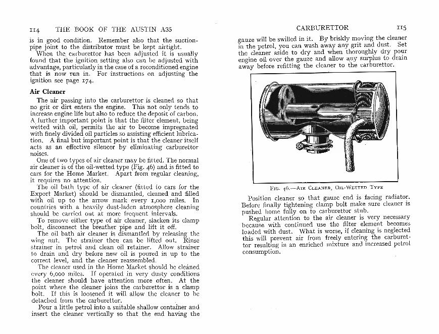
II4 THE BOOK OF THE AUSTIN A35
is in good condition. Remember also that the suctionpipe joint to the distributor must be kept airtight.
When the. carburettor has been adjusted it is usuallyfound that the ignition setting also can be adjusted withadvantage, particularly in the case of a reconditioned engine!ha~ . is now run in. For instructions on adjusting theignition see page 174.
Air CleanerThe air passing into the carburettor is cleaned so that
~o grit or d!rt ~nters the engine. This not only tends tomcrease engm e life but also to reduce the deposit of carbon.A.further.imp~rtant p~int is th~t the filter element, beingwetted with oil, permits the air to become impregnatedwith finely divided oil particles so assisting efficient lubrication. A final but important point is that the cleaner it selfac!s as an effective silencer by eliminating carburettornoises,
One of two types of air cleaner may be fitted. The normalair cleaner is of the oil-wetted type (Fig. 46) and is fitted to:ars fo~ the Home ~arket. Apart from regular cleaning,It requires no at tent ion ,
The oil bath type of air cleaner (fitt ed to cars for theExport Market ) should be dismantled, cleaned and filledwith oil up to the arrow mark every 1,000 miles. Incountries with a heavily dust-laden atmosphere cleaningshould be carried out at more frequent intervals.
To r~move either type of air cleaner, slacken it s clampbolt, disconnect the breather pipe and lift it off.
.The oil bath air cl.eaner is dism antled by releasing thewmg nut. The stramer then can be lifted out. Rinsestrainer in petrol and clean oil retainer. Allow strainerto drain and dry befor e new oil is poured in up to the
rrect level, and the cleaner reassembled.The cleaner used in the Home Market should be cleaned
every 6 ,0 0 0 miles. If operated in very dusty conditionsth e cleane r should have attention more often. At thepoint where the cleaner joins the carburettor is a clampbolt. If this is loosened it will allow the cleaner to bedetached from the carburettor.
Pour a little petrol into a suitable shallow cont~iher andinsert the cleaner vertically so that the end having the
CARBURETTOR IIS
gauze will be swilled in it. By briskly moving the cleanerin the petrol, you can wash away any grit and dust . Setthe cleaner aside to dry and when thoroughly dr y pourengine oil over the gauze and allow any surplus to drainaway before refitting the cleaner to the carbur et tor.
FIG. 46.- AIR CLEANER, OIL-W E TTED T Y PE
Position cleaner so that gauze end is facin g radi ator.Before finally tightenin g clamp bolt mak e sure cleaner ispushed home fully on to carburettor stub.
R egular attention to the air cleaner is very necessarybecause with cont inued use the filter element becomesloaded with dust. What is worse, if cleaning is neglectedthis will pr event air from freely entering the carburettor resulting in an enriched mixture and increased petrolconsumption.

CHAPTER IX
FUEL PUMP
T HE FUEL 'TANK-capacity 51 gallons-is situatedunder the floor of luggage compartment. As it is at
a lower level than the carburettor, which is mounted on nearside of engine, it is necessary that fuel should be supplied bypressure. This is effected by a mechanically operatedpump bolted on left-hand forward side of engine crankcase,with inlet pipe from rear tank. A lever is fitted to enablecarburettor to be primed by hand, should float chamb erbecome empty due to evaporation. If petrol app ears to beleaking from edge of diaphragm, tighten cover screwsalternately. Sometimes such leakage may actually comefrom one of the pipe unions causing fuel to run down topump and collect around diaphragm flange.
The pump mechanism is so arranged that when the floatchamber is full and the needle valve closed the pressureset up in the pump prevents the diaphragm from movingand supplying further petrol although the operating armmay continue working.
The pump (Fig. 47) is similar in action to an ordinaryplunger pump except for the fact that the plunger in the .latter is replaced by a flexible diaphragm of large diameter.As the cam moves the rocker arm outwards, it brings thediaphragm downwards thus creating a vacuum in the sediment chamber and drawing fuel from the tank throughthe inlet valve. As the cam turns, the rocker arm movesinwards causing a diaphragm to rise by the action of thecompression spring beneath it. This forces fuel throughthe outlet valve, since the inlet valve is now closed againstits seating to which it is held by a small compressionspring.
Before it can enter the diaphragm chamber, fuel mustpass through a fine filter gauze (I0, Fig. 47). This should beexamined and cleaned if necessary every 2,000 miles.
Access is gained by removing dome cover, after unscrewing retaining screw, when filter gauze itself may be lifted off
116
FUEL PUMP II7
its seating. Clean it with air from a tyre pump, or withpetrol. At the same time, clean out sediment chamber.On replacement do not overtighten filter-cover retainingscrew but tighten only sufficiently to ensure a fuel-tightjoint. Fit a new cork gasket under filter cover andmake certain that fibre washer has been replaced underhead of retaining screw when refitting cover. Check allpump-mounting set-screws and petrol pipe unions fortightness.
FIG. 47.-A SECTION THROUGH FUEL PUMP
I Diaphragm Pull- rod, and 2 Spring. 3 Diaphragm. 4 Pump Chamber. 5 SedimentDrain Plug and 6 Chamber. 7 Inlet Union. 8 Delivery Valv e and 9 Port . 10 GauzeFilter. II Cork Sealing Washer. 1 2 Inl et Valve. 13 Camshaft Eccentric. 14 Camshaft . 15 Anti-rattle Spring. 16 Connectin g Link. 17 Rocker Ann and 18 Pi vot
Pin
The inlet and outlet spring-loaded valves are so arrangedthat they permit fuel to pass only in one direction. Theinlet valve faces upwards, and the delivery valve downwards. Upward movement of the diaphragm can onlyforce petrol through the delivery valve, raising it to allowpetrol to escape past it on its way to the carburettor. Onthe other hand, when the diaphragm is drawn downwardsthe delivery valve moves downwards against its seatingwhilst the inlet valve opens and allows petrol to be drawnirom the tank by suction. From this it should be clear

u8 THE BOOK OF THE AUSTIN A3S
that fuel is supplied to the carburettor by an up-and-down~ovement of .the diaphragm and this alternately causes themlet and delivery valves to function.
The pump rocker arm may cont inue to operate evenw~en . the float chamb er is filled and virtually no fuel isbemg demanded. When the float chamber is filled thefloat rises to close the needle valve, thus cutting off any
FIG. 4 8.-Fu EL P UMP E X PL OD ED
I Retaining Screw, 2 ,Fibre Washer. ~ Cork Sealing Washer. 4 GauzeFil ter. 5 Dehvery Union, 6 Inlet Union . 7 Sediment Drain Plu g and
Wash erN ote: Priming lever is near NO. 7
fur ther supply of fuel. The next downward movementof the diaphrag~ draws a further supply from the t ank tothe pum p.. ThIS supply cannot be pumped into the carburettor, smce the needle valve is shut. The diaphragm ofth e fuel-pump inlet is held downwards unable to force thefuel past the needle valve of the carburettor. Thus therocker arm of the pump merely rises and falls within thelower slotted link of the diaphragm assembly. As soonas the carburettor requires more fuel, and when the needle
FUEL PUMP u9
valve opens, the diaphragm will rise thus forcing the petrolinto the float chamber.
Once the diaphragm has risen sufficiently the rocker arm,through its linkage, will again draw it down . According tothe requirement s of the float chamber so will the diaphragmrise. Thus it will be seen that the diaphragm can be helddown by back pressure in the pipe leading to the carburettor. When further supplies of fuel are required, however ,the compression spring will move the diaphragm upwardsto supply the additional fuel. The rocker arm then drawsdown the diaphragm and the pump re-charges itself fromthe fuel tank. As long as the engine is running a supplyis always available to maintain a const ant level in thefloat chamber through the medium of the needle valve.
A small compression spring holds the rocker arm in acontinuous contact with the camshaft. The rocker armcarr ies the link for the fuel-pump diaphragm.
From the above description it will be seen that the fuelpump is automatic in action and simple in operation. Aslong as the filter is kept clean and any sediment is periodically drained from the sediment bowl, the unit will functionindefinitely.
As mentioned earlier, the fuel pum p is pro vided with alever for priming purposes. If the carburettor float chamber is not full a slight pumping resistance is felt before thelever reaches its stop . Thi s resistance ceases when thechamber is full . To test the pum p in position, switch offthe engine and disconnect the fuel pump at the carburettorend leaving a free outlet from the pump. On turning overthe engine by hand there should be a well defined spurtof fuel at every working stroke of the pump-that is, onceevery two revolutions of the engine.
One important point must not be overlooked. Thehand-priming lever cannot operat e the diaphragm if it isheld down by the cam having moved the rocker arm out wards, thus drawing it down. If this is so, although thehand-primer lever can be operated, it will not be felt tomove the diaphragm downwards. Thus, it will be necessary to turn the engine approximat ely one full revolution,so bringing the cam clear of the rocker arm,and allowingthe diaphragm to return to the uppermost position.
It will be understood that the hand-primer lever will not
120 THE BOOK OF THE AUSTIN A3S FUEL PU MP 121
operate the diaphragm if the float -chamber needle valve isclosed, for the back pressure in the petrol pipe naturally willhold the ' diaphragm in the lower position.
Fuel Supply Failure
Should the engine stop because the pump has not maintained the correct level in the float chamber, ascertain thatthere is fuel in the tank. Even if the gauge indicates thatthis is so it is as well to make a positive check by dippinga clean rod or stick into the tank to ascertain that fuel isactually there. Elementary as this advice may seem it is,nevertheless, a fact that garage breakdown vehicles haveresponded to calls for help when all that was wrong wasthat the fuel t ank was empty I Sometimes fuel gaugesbecome deranged and in consequence give an incorrectleading. It is a wise precaution always to carry a sparetin of petrol in the boot- even if only to help , the otherfellow' sometimes I
If it is est ablished that -there is fuel 'in the tank, thequickest method of checking the faulty component is todisconnect the fuel pump from the carburettor at the floatchamber unit. T est the flow from the fuel pump by turning the engine as suggested on page IIg. Should fuel bereaching this point it is obvious that the stoppage mustbe in the carburettor. In this case, cleaning it with specialattention to the needle valve will probably rectify matters.
Suppose you find that the carburettor is all right andassume the fault lies somewhere else. It may be that fuel is not being discharged from the pipe you disconnectedfrom the pump. Disconnect the pipe from the pump againand turn the engine in case there is some blockage in thepipe its elf. If again there is no petrol temporarily reconnect the fuel pipe to the pump. Place your mouth overthe end and find out if you can suck fuel through . Shouldthere be an obstruction clean the filter and sediment chamber of the pump, as previously described. On the otherhand, if you can draw petrol-remembering that as it has amost unpleasant t aste you should avoid taking a mouthful- it will probably mean that one of the pump valves is notseat ing correctly.
Alternatively, the diaphragm may be punctured or-a
very rare occurrence- the diaphragm spring has broken.This can usually be noticed when the engine is turned, forthe characteristi c breathing sound will not occur at theinlet orifice because the diaphragm will not be actuatedcorrectly.
In either case, open up pump chamber (4, Fig. 43) todisclose filter screen. Wash out sedimerit bowl and cleanfilter as already instruct ed. .
A syringe may be used to force fuel to delivery and inlet(8 and 12, Fig . 47) valves to remove-any grit that may bepreventing a proper seating.
If the pump continues to refuse to function when assembled, and the diaphragm screws are tight, see if the variousunion nuts are tight . An air leak on the suction side ofthe pump could prevent the pump from working.
If you again cannot draw petrol through aft er cleaningthe filter and re-assembling the pump, disconnect the mainpipe to the pump. Apply suction to the end of it, and ifthere continues to be no response it probably is due to anaccumulation of fluff or dirt drawn into the pipe from thetank. It may be this encumbrance can be cleared byblowing down the pipe. Remember, however, that whilstyou may clear the pipe temporarily the dirt remains inthe tank so that the trouble may recur at _any time. Insuch a case the tank should be drained and cleaned at theend of your journey and any fuel remaining should befiltered.
Leaking Fuel PumpAn important point to remember is th at leakage is
usually evidenced only when the engine is running or hasstopped. It is only under these conditions that the pumpis known to be primed.
Although fuel may be seen to be dripping from the pumpthis is-not necessarily proof that the pump it self is at fault.The golden rule in diagnosis is : ' Never jump to conclusions.' First wipe the exterior of the pump carefully witha rag and see whence the fuel is coming. The leak may bedue to a loose pipe connection or-should the pump coverhave been removed-from the gasket fitt ed ' between the
-cover and body, or from 'the gasket beneath the bolt head.
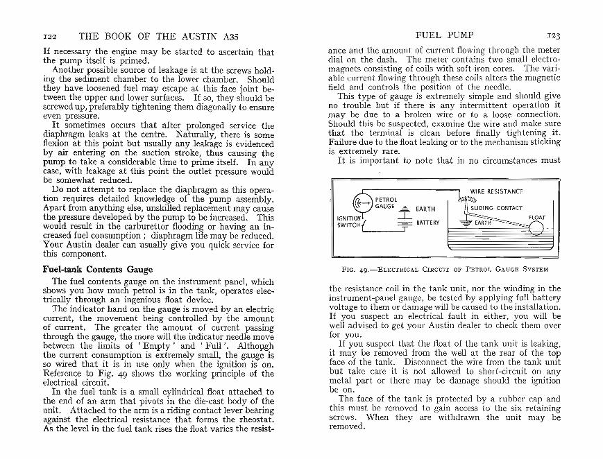
I22 THE BOOK OF THE AUSTIN A3S
If necessary the engine may be started to ascertain thatthe pump its elf is primed.
Another possible source of leakage is at the screws holding the sediment chamber to the lower chamber. Shouldthey have loosened fuel may escape at this face joint between the upper and lower surfaces. If so, they should bescrewed up, preferably tightening them diagonally to ensureeven pressure.
.It sometimes occurs that after prolonged service thediaphragm leaks at the centre. Naturally, there is someflexion at this point but usually any leakage is evidencedby air entering on the suction stroke, thus causing thepump t? take a consider.able .time to prime itself. In anycase; WIth leakage at this point the outlet pressure wouldbe somewhat reduced.
Do not attempt to replace the diaphragm as this operation requires detailed knowledge of the pump assembly.Apart from anything else, unskilled replacement may causethe pressure developed by the pump to be increased. Thiswould result in the carburettor flooding or .having an increased fuel consumption; diaphragm life may be reduced.y ~ur Austin dealer can usually give you quick service forthis component.
Fuel-tank Contents GaugeThe fuel contents gauge on the instrument pan el, which
shows you how mu ch petrol is in the tank, operates electrically through an ingenious float device.
The indicator hand on the gauge is moved by an electriccurrent, the movement being controlled by the amountof current. The greater the amount of current pas singthrough the gauge, the more will the indicator needle movebetween the limits of 'Empty' and ' Full ' . Althoughthe current consumption is extremely small, the gauge isso wired that it is in use only when the ignition is on.Reference to Fig. 49 shows the working principle of theelectrical circu it.
In the fuel tank is a small cylindrical float attached tothe end of an arm that pivots in the die-cast body of theunit. Attached to the arm is a riding contact lever bearingagainst the electrical resistance that forms the rheost at.As the level in the fuel tank rises the float varies the resist-
FUEL PUMP I 23
anc e and the amount of current flowing through the meterdial on the dash. The meter contains two small electromagnets consisting of coils with soft -iron cores. The variable current flowing through these coils alters the magneticfield and controls the position of the needle.
This t ype of gauge is ext remely simple and should giveno trouble but if there is any intermittent operation itmay be due to a broken wire or t o a loose connect ion.Should this be suspected, examine the wire and make surethat the termin al is clean before finally ti ghtening it.Failure due to the float leaking or to the mechanism stickingis extremely rare.
It is important to note that in no circumstances must
PETROLGAUGE .£:. EART H
I= BATTERYL- ~T
FIG. 4 9.-ELE CT RI CAL C IRCUIT OF P ETROL G AUGE SYSTEM
the resistance coil in the tank unit, nor the winding in theinstrument -panel gauge, be test ed by applying full batteryvolt age to them or damage will be caused to the installation.If you suspect an electrical fault in either, you will bewell advised to get your Austin dealer to check them overfor you .
If you suspect that the float of the tank unit is leaking,it may be removed from the well at the rear of the topface of the tank. Disconnect the wire from the tank unitbut take care it is not allowed to short-circuit on anymetal part or there may be dam age should the ignitionbe on.
The face of the tank is protected by a rubber cap andthis must be removed to gain access to the six retainingscrews. When they are withdrawn the unit may beremoved.

1 2 4 THE BOOK OF THE AUSTIN A3STake care not t o bend or strain the float arm other than
as it is when supplied or it s correct movement between thelimits of it s travel may be affected . The float arm is provided with t op and bot tom stops to prevent the contactarm overrunning the resistance.
?hould the gasket be damaged when replacing the tankumt fit a new one and reconnect the gauge wire t erminal.The cover plate should then be replaced and secured withthe screws around it s edge. See that the gaske t fitted tothe cover plate is in good order for this prevent s dust ordirt from working its way into the interior of the car.
CHAPTE R X
COOLING SYSTEM
rrHE ENGIN E OF THE A35 is wate r-cooled, sealedand pressuri zed . This pressure raises the. boiling
point of the coolant (water) to 224 0 F . A pressure reliefvalve, located in the radiator filler cap, opens at approximately 4 lb. per sq . in . pressure. The cooling systemincludes a centrifugal water pump driven by a triangular
FIG. sO.-COOLING S Y STE MI Thermostat. 2 Oiling Plu g for Water Pump
V belt from the generator. The spring-loaded carbon-typegland requires no ' adjustment. A therm ost at is fitted atwater outlet on cylinder head to assist rapid warming up a very desirable feature (I, Fig. 50).
A useful fitting as an extra is an interior heater for thecar. Connected to the cooling system, it is mounted on theengine bulkhead and incorp orat es a core through which hotwater from the engin e can be circulate d.
1 25

126 THE BOOK OF THE AUSTIN A3S COOLING SYSTEM 127A small elect rically-driven fan is fitted to the heat er unit
so tha t warm air can be circulated through the car body.The method of operating the heater fan is to turn thecontrol switch situated to the centre of the instrument pa nelin a clockwise direction (5, Fig. 2). The heater installati onis dealt with later in this chapter.
Any petrol engine becomes hot in use because thepetrol/air mixture when ignited develops intense heat . Unless this is dissipated norm al lubrication would becomeimpossible for the oil film would break down result ing inmetallic seizure. Cooling is effected by passing waterthrough the radiator and circulating it around the cylinders.The water passes down through the core of the radiatorto a tank at the bottom, thence through a connecting hoseto the pump. From here it circulates around the cylindersto find its way through passages into the cylinder head,then around the exhaust ports, etc ., finally to reach theheader tank at the top of the radiator by way of the upperconnecting hose.
As soon as the engine is started the pump, driven by theV belt, circula tes the water through the system assistingthe natural t endency of the water to follow the coursedescribed above, for hot water rises and cool water falls.Th e heat transferred to the water from the engine is dissipated by the curre nt of air through the radiator by theforward progress of the car , assisted by a two-bl aded fanmounted on an extension of the pump shaft and situatedimmediately behind the radiator (3, Fig. 51).
ThermostatTo ensure maximum engine efficiency it is essential to
keep the operating t emperatures of the engine within certain limit s. This is done by the thermostat , located in thewat er outlet at the front of the cylinder head (2, Fig. 51).
The thermostat consists of a metallic bellows filled with avolat il liquid that controls a mu shroom valve. Whentheengine is cold, this valve is closed, a by-pass being fitte d toallow for slight circulation. On starting the engine, theflow of wat er t o the radiator is temporarily rest ricted ,resulting in a rapid increase in the water temperature in thepower unit. The heat of the water in contact with the
9
8
7
FIG. SI.-TYPI CAL COOLI N G S YST E M
I Piller Cap. 2 Thermostat. 3 Pa n Blade. 4 Radiator Drain Tap.S Water Pu mp. 6 Cylinder Block Drain Tap . 7 Heater Tap, 8 Peed
Pipe and 9 Return Pipe
bellows causes the valve to open gradually through expansion, ult imately allowing full flow to the radiator.
The thermostat is detachable so that should occasion ariseit can be removed from it s housing and the hose reconnected. This avoids laying up the car.
If the thermostat is tight there are two holes on the topthat may be utilized to ease it from the casting .
When the system has been complet ely emptied, it isessential to wait a minute or two after refilling before finallytopping up, t o allow air t o escape through the thermostatvalve .
The thermostat is set by the manufacturers t o open at1580 to 1670F. and it cannot be alte red. When decarbonizing it is desirable to t est the thermostat by imme rsing it inwater that has been raised to the requisit e temperature. Ifthe valve fails to open a new unit should be fitt ed.
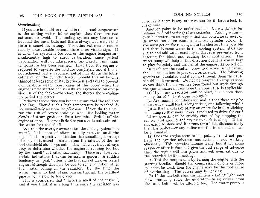
1 28 THE BOOK OF THE AUSTI N A35
OverheatingIf you are in doubt as to what is the normal temperature
of the cooling water, let us explain that there are twoextremes to avo id. The cooling system may become sohot that the water boils and this is always a sure sign thatthere is something wrong. The other ext reme is not soreadily ascertainable because there is no visible sign . Itis when the system is too cool or the engine temperatureinsufficiently high t o effect carburation, since perfectvapo rization will not take place unless a certain minimumtemperature has been reached. Heat from the engine isrequired to vaporize the mixture completely and if this isnot achieved partly vaporized petrol may dilute the lubricating oil on the cylinder bores. . Should this oil becomethinned it loses some of its effectiveness and fails to preventcylinder-bore wear. Most cases of this occur when theengine is first started and usually ar e aggravated by exces-
-sive use of the choke-therefore, the short er the warminglup period the better.
Perhaps at some time vou become aware that th e radiatoris boiling. Should such a high temperature be reached donot immediately unscrew the fi ller cap. If you do this yourun the risk of severe scalding, when the b oiling waterclouds of steam gush out like a fountain . Switch off theengine at once. There is little else you can do but wait untilthe water has cooled off.
As a rule the average owner takes the cooling system ' ontrust' . This state of affairs usually remains until theengine boils-a positive indication that something is wrong;The engine is sound-insulated from the interior of the carand the shield also keeps out smells. Thus, it is not alwayseasy to determine whether the engine is running too hotby the ' smell' of heat ed machinery. There are, however ,certain indic ations that can be used as guides. A suddentendency to ' pink ' often is the first sign of an overheat edengine, although this may be due to some condition otherthan water boiling in the radiator. By the time thewat er begins to boil, steam passing through the overflowpipe is not visible to the driver .
If it is considered that ' there's a smell of hot engine ',and if you think it is a long time since the radiator was
COOLING SYSTEM 129
filled , or if there is any other reason for it , have a look tomake sure.
Another point t o be underlined is : Do not fill up theradiator with cold water if it is overheated. Adding watereven hot water-to an engine that has boiled away most ofit s water can often cause a cracked cylinder block. Ifyou must get on the road again in the shortest time possibleand there is some water in the cooling system, start theengine and add water carefully so that it is preve nte d fromentering the block and causing local contraction. Thewater-pump will help in thi s direction but it is always bestto play for safety and wait until the engine has cooled off.
So much for the results. Now to discover what causedthe boiling and how to prevent a recurrence. The followingqueries are tabulat ed and if you go through them the causeshould be discovered. Do not be tempted to stop as soonas you think the answer has been found but work throughthe questionnaire in case more than one cause is applicable.
(I) If you use a radiat or muff or blind, has it been thoroughly furled? Is it open enough ?
(2) Are running conditioils unusual in that there may bea heat wave, a full load, a long incline, or a following wind?
(3) Is the hand-brake partly on or are the brakes stickingor binding so that more power is required to drive the car?
These queries can be quickly checked by stopping thecar on level ground and trying to push it along. If thiscan easily be done and if it runs for a little dist ance freelythen the brakes-or any st iffness in the transmission-canbe eliminated.
(4) Does the engine seem to be ' pulling'? If not, perhaps the igniti on adv ance mechanism is not workingefficiently. This operates automatically but if for somereason or other it does not give the full ran ge of advancethen the engine will lose power and will overheat due tothe retarded ignit ion setting.
(5) Test the compression by turning the engine with thestarting-handle. Should the compression of one or morecylinders be weak then the engine may be the root causeof overheating. The valves may be leaking.
(6) If the fan-belt slips the ignition warn ing light mayglow errati cally since the generator- being driven fromthe same belt- will be affected too. The 'water-pump is

FIG. 52.-V-BELT ADJUSTMENT
A Generator Rear Bracket Bolt and B i ts Adjusting Nut.C Swinging Link Locknut
also dr iven from the fan-belt so that a slack belt maythus affect both fan and pump . But do not decide toeliminate this trouble by having the belt too tight. If thisis done, not only will the belt wear quickly but the pump,dynam o bearings and fan-shaft will be heavily loaded.Increased wear will be the inevitable result. The beltshould be sufficiently t ight to allow it t o be moved laterallyabout I in . in each direction .
131COOLING SYSTEM
to test the car on the road , however, for then people otherthan the neighbours may have something to say !
(8) Front wheels that are 'to~d in ' or ' to ed out ' ~oo
much can cause considerable resistan ce to forward motionas also can any stiffness in the gearbox or rear axle. Aquick check for transmission ~tiffness is to rai se one whe~l
at the rear- with the car suitably blocked up so that Itcannot move in either dir ection-and turn the wheel withthe handbrake off. It should be quite free to turn. If itis st iff this may be due to dragging brakes or to some othermisadjustment . .
(9) The cooling sys tem ~ay be block~d in one or more ofit s passages. Where possible clean ram wat~r sh<?uld beused an d this should be filtered when the radiator IS filledso that leaves and other foreign bodies are excluded . Toa greater or lesser extent tap water possesses undesirablesalt s that form scale on the inside of the system. For thisreason it is best to use only soft water such as rain water.
Rubber hose occasionally tends to shed its inn er sur faceand can obstruct the flow of water particularly since allwater has continually to pass through hoses at the top andbottom of the radiator.
FIG. 53.- RADIATO R
I Overflow Pipe. 2 Filter Cap. 3 Bonnet Cat ch
THE BOOK OF THE AUSTIN A3S130
To make adjustment, slacken bolts and raise or lowergenerator until desired degree of tension is obtained. Thensecurely lock generator in that position (see Fig. 52).
(7) A choked silencer or exhaust pipe may cause overheat ing and loss of power. This can usually be traced bylist ening to the exhaust note. If it seems to have amuffled hiss rather than a clear' beat' then an additionalcheck would be to disconnect the silencer and ascertain ifthe engine has more power without it . Do not be tempted

132 THE BOOK OF THE AUSTIN 'A3S COOLI NG SYSTEM 133
ment panel (Fig. 54). Upper lever regulates flow of airto windscreen for demisting or defrosting whilst lower leverregulates flow to interior for heating or ventilating. Thebooster fan is controlled by a switch situa ted above heat ercontrol panel.
The accompaning Table summarizes various controlpositions available for dealing with all types of weatherconditions.
Heater and D emisterThe Smith bui lt- in heating and demisting unit (optional
extra) utilizes the cooling-system water to heat air forcircul ation in interior and to windscreen for demisting anddefrosting. The engine thermostat maintains a temperature of 1580 to 1670 F . in cylinder block and since thethermostat enables the engine to warm up very rapidlyheat is available for the interior soon after start ing.
The heater consists of elect rically driven booster fan,bolted on left-hand side of engine bulkhead. It draws airthrough front grille and forces it along a large diameterflexible pipe into heater unit also situa ted on bulkhead.
Condit ionsHe a ting/Ventil a tin g Demisting/Defrost ing
Control Lever Position Control Lever Pos ition
dID rITh DI£n0 ", "",,,Sf DI,,.,.,.Of ' OEMIIT
® w.... HOT COl.D Of 'W" __ H
HOT rfi])
IdID0" DlMIST Ol,ItOST
"" ...." HOT ®
rffh dID0" DI>o'Sf DlfOOST dfu O<fO<Sf .....,.,.Of' - @' >ocT COLD - T n
FIG. 5 4 .-THE H EATER C ONTROL POSITIONS
I. No air supply tov ehicle in t erior
2 . W arm weathercold ventilatingair, cold air t owindscree n
3. W arm weathercold v entilatingair, m aximumair to windscreen
4. Cold weatherhot ve ntilat ingair, warm air towindscreen
5. Freezin g weather- maximum hotair to windscreen
Off '
'Cold'
' Cold '
Between 'Warm'and 'Hot' ac cording t o heatrequired
' Off '
, Off '
, Demist'
'Defr ost '
'Demist'
, Defrost '
Here it passes through a water-heated radiator into adistribution chamber where shutters, operated from heatercontrol panel, regulate its flow into interior of car.
Even without the fan switched on, air will be forced intocar and on to windscreen due to car 's motion providingthat the appropriate shutter in heating and demisting unitis open. At low v ehicle speeds, and particularly if maximum heat ing or ventilation is required, the fan should beswitched on. If necessary, air supply to interior can beentirely shut off-as, for instance, when in dense trafficto prevent ent ry of exhaust fum es, dust, etc.
The heating and demisting unit is controlled by twolevers operating in a quadrant mounted beneath instru-
If the heater is switched on when the engine is firststarted, hot air will not be obtained until the engine haswarmed up. Similarly, when the engine is thoroughly hotif the heater is switched off some little time will elapsebefore the heater unit cools completely.
When refilling the cooling system-should the enginehave been drained-there may be a tendency for an air-lockto form in the heater unit.
Once the engine is started the water pump will usuallyclear this air-lock aft er which the system may then befully topped up.

134 THE BOOK OF THE AUSTIN A3S COOLING SYSTEM I35
Care of the Radiator
If the radiator is topp ed-up when necessary no par ticularcare is required except periodically to inspect the hosesand clamps to make sure that they have not become looseso allowing water to seep through.
Some owners are quite happy on inspectin g the water levelwhen the engine is hot. A different story is told , however,when they look at it with the engine cold for then the waterhas cont rac ted and the level has gone down. On refillingit to the top some misgiving is felt when next it is found thatstill more water is required . What is not realized is thatif it were checked' hot ' then the normal level would bereached, for only the surplus is lost down the overflow.
In summer it is good practice to examine the radia torgrille t o see that it has not collected myriads of insects orleaves. This state of affairs restricts the amount of airpassing and so may give rise to overheating.
Every 1 2,000 miles the system should be flushed out;Open the drain t aps and drain off the water from theradiator and cylinder head. IF ANTI-FREEZE IS USED KEEPTHE WATER. Aft er all the water has run out carefullyprobe the tap orifice with a piece of wire. If the outlethas become blocked with sediment this action will clearit. Make sure that the rad iator drains fully.
Allow a cont inuous stream of water from a hose to flushout the system keeping the radiator drain tap open. Ifthe water is discoloured continue flushing until the watercomes out clear. Do not forget to replace the ant i-freezesolut ion if this was originally in the system. If you feelthere may be some sediment or foreign matter filter thewater when you pour it back.
The capacity of the cooling system is 8t pints.
Frost Precautions
If the t emperature falls sufficiently, the cooling waterwill freeze. In doing so it may set up sufficient pressureto split the cylinder block, cylinder head or radiator. Theresult of this can be expensive and it is well worth whileto take trouble- either by draining the cylinder block andradiator or using anti -freeze- t o prevent this calamity from
occurring. The cost of anti-freeze solution is so small,compared with the repair bill that can result from a ' freezeup " that no motorist need feel that he is emb arking onan expensive precaut ion.
The effect of the anti-freeze solution is to lower the
FIG. 5 5 .-RADIATOR DRAIN T AP . T o drain , turn t apA ant i-clockwise
temperature at which the water will freeze. If you followthe ~akers'. recommendations you will have adequate protection against any normal frost .
A point to note is that when a heat er is fitted, drainingthe cooling system in frosty weather may not prevent theheater radi~tor from freezing since it will trap a proportionof the cooling water. The use of an anti-freeze solutionis the only safe precaution in such circumstances.
There are several paraffin or petrol heating lamps on themarket that operate on the principle of the miner 's lamp.These can be ~sed under the bonne t to prevent the temperature from falling und uly. Electric heating devices-either
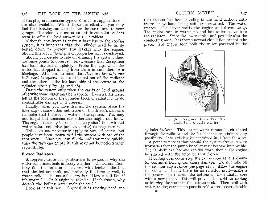
THE BOOK OF THE AUSTIN A3S COOLING SYSTEM 137
of the plug-in immersion type or direct-heat applicationsare also avail~ble. Whilst these are effective, you mayfind that freezmg can occur before the car returns to yourgarage. Therefore, the use of an anti-freeze solution doesseem to offer the best answer to the problem.
Although anti-freeze is entirely harmless to the coolingsystem, it is important that the cylinder head be firmlybolted down to prevent any leakage into the engine.Should this occur, the engine oil properties will be destroyed.
Should yo.u decide to rely on draining the system, thereare some pomts to observe. First, ensure that the systemhas been drained completely. Probe the taps when thewater has stopped issuing from them in case there is ablockage. Also bear in mind that there are two taps andboth must be opened-one at the bottom of the radiatorand the other orrthe left-hand side at the centre of thecylinder block (Figs. 55 and 56).
Drai?- the system only when the car is on level groundotherwise some water may be trapped. Even a little waterleft at the bottom of the cylinder block or radiator may doconsiderable damage if it freezes.
Finally, when you have drained the system, place thefiller cap or some other indication on the driver's seat as areminder that there is no water in the system. You maynot forg.et but someone else otherwise might not know.The engme can only be run for a very short time withoutwater before extensive (and expensive) damage results.
This does not necessarily apply to you, of course, butpeople have been known to fill the system with one of thetaps open! Since you can fill the radiator more quicklythan the taps can empty it, this may not be noticed whenreplenishing.
Frozen RadiatorsA frequent cause of mystification to owners is why the
water sometimes boils in frosty weather. On examination,they find the radiator is covered with icicles indicatingthat the bottom tank, and probably the hose as well, isfrozen solid. The natural query is: 'How can it boil ifit's frozen?' Or it might be asked : • If it's frozen, whydoesn't the boiling water melt the ice? '
Look at it this way. Suppose it is freezing hard and ,
that the car has been standing in the wind without antifreeze or without being suitably protected. The waterfreezes. The driver starts the engine and drives away.The engine rapidly warms up and hot water passes intothe radiator. Since the lower tank-and possibly also theconnecting hose-has frozen normal circulation cannot takeplace. The engine soon boils the water pocketed in the
FIG. S 6 .-CYLIKDER BLOCK TAP. Todrain, turn A ant i-clockwise
cylinder jackets. This heated water cannot be circulatedthrough the radiator and the fan blades also minimize anypossibility of the exist ing ice contained in it from thawing.
A point to note is that should the system freeze in veryfrosty weather the pump impeller may become immovable.The fan-belt can become rapidly worn should the enginebe started with the impeller thus frozen .
If boiling does occur st op the car as soon as it is knownfor continual boiling can cause damage. Do not take offthe radiator cap at once (see page 128). Allow the engineto cool and-should there be no radiator muff-make atemporary shield across the bottom of the radiator corewith a newspaper. This will prevent the cold air coolingor freezing the water in the bottom tank. Then refill withwater, taking care not to pour in cold water in considerable
K
138 THE BOOK OF THE AUSTIN A3S
volume if the engine is st ill hot for this may start adistortion crack.
Allow the engine to run at a steady ' t ick-over ' for alittle time when it is probable that sufficient heat will betransmitted through the radiator to cause the ice to melt.If it does not do so an effective method is to place ragsagainst the part of the system sti ll frozen and keep themsoaked with boiling water.
CHA PTER X I
TRANSMISSION
T HE CLUTCH OF THE A35 is simple yet robustin construction and its ad justments have been re
duced to a minimum. Provided a few elementary precautions are followed no t rouble should be encountered .If wear occurs in course of time it will be necessary toremove the engine unit. This job is best left to yourAust in dealer who has the necessary specialized tools andequipment for the work.
The clutch is of. the single dry-plate type with tworenewable facings , one each side of the disc. An ingenioussystem is used whereby the disc carrying its faced liningsis connected to its hub. Th is drives the main shaft of thegearbox through a system of thrust springs thus ensuringa smooth cushioned dr ive (Fig. 57).
This disc is mounted on, and is free t o slide on, thefirst motion shaft of the gearbox, the front end of which iscarr ied in the centre of the crankshaft flange in a bush.When the disc is rotated it also rotates the first mot ionshaft through the splines on which it is mounted . Thefront side of th e disc can be pressed into contact with themachined face of the flywheel. From this you will seethat if the disc be pushed strongly enough against the flywheel it will drive through the gearbox. If there is nopressure against it, the flywheel will turn whilst the firstmoti on shaft and the disc remain stationary. The bushcarrying the fron t end of the first motion shaft turns withthe crankshaft .
A pressure plate is used to transmit the drive from theengine to the clutch disc. This consist s of a cast plate,roughly the same size as the facing on the clutch disc. Itis mounted in a cover, with six compression springs betweenthe cover and pressure plate . When the cover is boltedto the flywheel the clutch disc is tightly gripped betweenthe flywheel face on the one side and the pressure plat e onthe other.
I39

THE BOOK OF THE AUSTIN A35
.--- - - --S?
TRANSMISSION I4I
There are three hinged levers so mounted that when theirinner ends are pressed towards the flywheel their outerends move rearwards. Hinged on suitable brackets fixedto the cover, they move the pressur e plate rearwards sofreeing the clutch disc from the flywheel and pressure plate.The clutch is then ' out'.
The three release levers are connecte d to a suitablerelease plate and when the clutch pedal is depressed itmoves forwards a release bearing. Thi s in turn forces thelevers inwards, freeing the clut ch as already described.
The three levers are accurately set with reference to oneanother. The release bearing requires no lubrication andthus, apart from lubricating the clut ch-linkage joints, theonly attention likely to be required is that of adj ustingthe free travel of the clut ch pedal.
You will remember being advised never to place the footon the clutch pedal except when using it. Continuouslyresting your foot on this pedal can have two bad results:(a) It brings into contact the release bearing with therelease plate and so causes this to wear unduly; (b) acertain definite pressure is required to be transmitted tothe clut ch disc to assure a solid drive. Foot pressure onthe clutch pedal can reduce the grip on the clutch discand thus it may slip . Any clutch slip is undesirablebecause extreme local heat is rapidly generated and theworking sur faces of the clutch disc can overheat or evenburn out. Clutch slip is easily recognizable when present.Usually, it is noticed that any sudden acceleration on thetop gear causes the engine to speed up without any corresponding rise in road speed.
In extreme cases the engine may' race ' on approachinga slight gradient. Great difficulty may occur in startingoff on bottom gear because the drive will not take up ,the engine appearing to have no connection with the transmission even when the clutch pedal is fully back. Fromthis you will see that there is considerable loss of powerand speed.
Even if some slipping has taken place and you adjustthe clutch pedal, the heat that was generated might havedistorted the working parts of the clutch so that it mayno longer give sat isfactory service.
Insistence on clut~h-pedal adjustment is made here
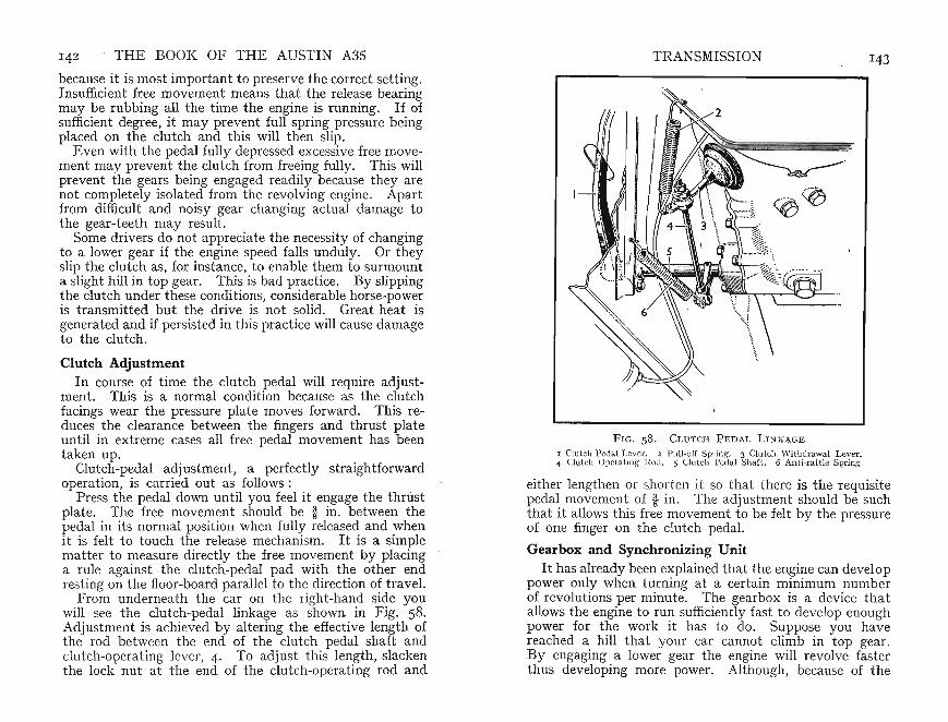
TEE BOOK OF THE AUSTIN A3S TRANSMISSION I43because it is most important to preserve the correct setting.Insufficient free movement means that the release bearingmay be rubbing all the tim e the engine is running. Ifofsufficient degree, it may prevent full spring pressure beingplaced on the clutch and this will then slip.
Even with the pedal fully depressed excessive free movement ma y prevent the clut ch from freeing fully . Thi s willprevent the gears being engaged readily because they arenot completely isolated from the revolving engine. Apartfrom difficult and noisy gear changing actual damage tothe gear-teeth may result.
Some drivers do not apprecia te the necessity of changingto a lower gear if the engine speed falls unduly. Or theyslip the clutch as, for instance, to enable them to surmounta slight hill in top gear. Thi s is bad practice. By slippingth e clut ch under these conditions, considerable horse-poweris transmitted but the drive is not solid. Great heat isgenerated and if persisted in this practice will cause damageto the clutch.
Clutch AdjustmentIn course of time the clutch pedal will require adjust
ment. This is a normal condition because as the clutchfacings wear the pressure plate moves forward. This reduces the clearance between the fingers and thrust plateuntil in extreme cases all free pedal movement has beentaken up.
Clutch-pedal adjustment, a perfectly straightforwardoperation, is carried out as follows:
Press the pedal down until you feel it engage the thrustplate. The free movement should be i in. between thepedal in its normal position when fully released and whenit is felt to touch the release mechanism. It is a simplematter to measure directly the free movement by placinga rule against the clutch-pedal pad with the other endrest ing on the floor-board parallel to the direction of travel.
From underneath the car on the right-hand side youwill see the clutch-pedal linkage as shown in Fig. 58.Adjustment is achieved by altering the effective length ofthe rod between the end of the clutch pedal shaft andclutch-operating lever, 4. To adjust this length, slackenthe lock nut at the end of the clutch-operating rod and
F I G. 5 8 .- CLUT CH PEDAL LINKAGE
I Clutch Peda l Lever. 2 Pull-off Spr ing. 3 Clutch Wi thdrawal Lever .4 Clutch Opera ting 1'0<1. 5 Clutch Pedal Sha ft. 6 Anti-rattle Spr ing
either lengthen or shorten it so that there is the requisitepedal movem ent of it in . The ad justment should be suchthat it allows this free movement to be felt by the pressureof one finger on the clutch pedal.
Gearbox and Synchronizing UnitIt has already been explained that the engine can develop
power only when turning at a certain minimum numberof revolutions per minute. The gearbox is a device thatallows the engine to run sufficiently fast to develop enoughpower for the work it has to do. Suppose you havereached a hill that your car cannot climb in top gear.By engaging a lower gear th e engine will revolve fast erthus developing mote power. Although, because of the
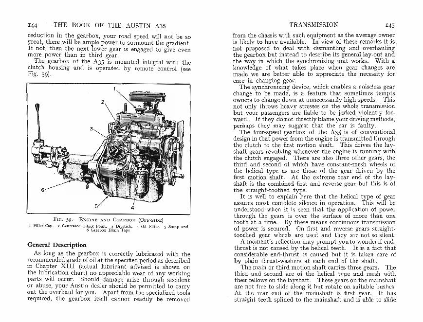
I44 THE BOOK OF THE AUSTIN A3S TRANSMISSION I45
reduction in the gearbox, your road speed will not be sogreat , there will be ample power to surmount the gradient.If not, then the next lower gear is engaged to give evenmore power than in third gear.
The gearbox of the A35 is mou nted integral with theclutch housing and is operated by remote control (seeFig. 59).
F IG. 59.- ENGINE AN D G E ARBOX (OFF-SIDE)
I Filler Cap. 2 Genera tor Oiling Poin t . 3 Dipstick. 4 Oil Filter. 5 Sum p and6 Gearbox Drain Taps
General DescriptionAs long as the gearbox is corr ectly lubricated with the
recommen ded grade of oil at the specified period as describedin Chapter X III (actual lubricant advised is shown onthe lubrication chart) no appreciable wear of any workingparts will occur. Should dam age arise through accidentor abuse, your Austin dealer should be permitted to carryout th e overhaul for you. Apart from the specialized toolsrequ ired, the gearbox itself cannot readily be removed
from the chassis with such equipment as the average owneris likely to have available. In view of these remarks it is .not proposed to deal with dismantling and overhaulingthe gearbox but instead to describe its general lay-out andthe way in which the synchronizing unit works. With aknowledge of what takes place when gear changes aremade we are better able to appreciate the necessity forcare in changing gear.
The synchronizing device, which enables a noiseless gearchange to be made, is a feature that sometimes temptsowners to change down at unnecessarily high speeds. Thisnot only throws heavy stresses on the whole transmissionbut your passengers are liable to be jerked violently forward. If th ey do not directly blame your driving methods,perhaps they may suggest th at the car is faulty.
The four-speed gearbo x of th e A35 is of conventionaldesign in that power from the engine is transmitted throughthe clutch to the first motion shaft. This drives the layshaft gears revolving whenever the engine is running withthe clutch engaged. There are also three other gears, thethird and second of which have constant -mesh wheels ofthe helical type as are those of the gear driven by thefirst motion shaf t. At the extreme rear end of the layshaft is the combined first and reverse gear but this is ofthe st raight-toothed type.
It is well to explain here tha t the helical type of gearassures most complete silence in operation. This will beunderstood when it is seen that the application of powerthrough the gears is over the surface of more than onetooth at a tim e. By these means continuous transmissionof power is secured. On first and reverse gears straighttoothed gear wheels are used an d they are not so silent.
A moment's reflection may prompt you to wonder if end..thrust is not caused by the helical teeth . It is a fact thatconsiderable end-thrus t is caused but it is taken care ofby plain thrust-washers at each end of the shaft.
The main or third motion shaft carries three gears. Thethird and second are of the helical type and mesh withtheir fellows on the layshaft. These gears on the mainshaftare not free to slide along it but rot ate on suitable bushes.At the rear end of the mainshaft is first gear. It hasstraight teeth splined to the mainshaft and is able to slide
feel a slight resistance as this clicks into neutral or intothe particular gear engaged. This is caused by ~he plungerentering the locat ion in the selector shaf t. It IS the pressure set up by the plunger that retains the particular gearin mesh. You will now appreciate the necessity for alwaysmoving the gear lever fully into posit~on , otherwise thedrive will not be taken on the whole WIdth of the engaging t eeth and these, therefore, may be damaged. Also,there will be a considerable tendency for the gears to flyout of mesh.
The gear-change lever mechanism is correctly set whenthe car is assembled at the works and should not normallyrequire any adjustment .
146 THE BOOK OF THE AUSTIN A35
along to allow first or second gear to be meshed. Therear end of the mainshaft , which is extended rearwar dsis mounted on a ball race in the gearbox and on anotherin the extension housing. The front of the mainshaft ishoused in a bushed bearing in the first motion shaft.Consequen tly, each shaft can turn independently of theother or together they can turn as may be required.
!he synchronizing device-used when engaging top,t~lrd and s~cond gear-assur es a silent engagement andwill be descnbed more fully later. At the moment it mayhelp to understand how the various changes of gear ratioare obtained.
TRANSMISSION 147
Gear Selection MechanismAt the side of the gearbox there are three shafts known as
selector shafts. Mounted on each is a selector fork theforked end of which enters an annular groove in the slidinggear or. coup ling sleeve with which it is associated. Topand third selector fork has three positions- forward toengage top gear, middle or neutral posit ion, and rearwardto engage third gear .T~efirst and second gear selector also has three positions
movmg forward to engage second gear, neutral posit ionin the middle and rearward to engage bottom gear. Thereverse gear selector has two positions: neutral and reversewhen moved forward .
Ignoring reverse for the moment , each selector fork has aspring-loaded steel plunger that can enter any one of thethree notches machined in the selector shaft along which itslides. From this you will see that once it has been movedso that the plunger enters the location or notch the springloaded plunger will retain the fork in place.
Each selector shaft is moved by the gear-lever bottomextension. This is free to move sideways and also backwards and forwards. Thus, it can engage the machi nedslot in anyone of the three selector forks.
Th e reverse gear selector fork similarly has a springl~aded plunger. Since it is merely necessary here to proVIde for neutral and reverse gear position s, however, thereare only two locations in the shaft .
As you move the gear lever into or out of neutral you
Top GearWhen top gear is engaged the drive is direct . That is
to say, the top-gear synchronizing device locks the gearboxmainshaft to the first motion shaft so that they revolve atthe same speed. The gears on the lay~haft , however, ~redriven by the constant-mesh gears and III turn rotate thirdand second gears on the mainshaft although these lattert ransmit no drive to it, merely revolving idly.
Third GearWhen the gear lever is moved into the third position
the synchronizing device moves rearwards locking the thirdgear to the mainshaft. It will be seen that when the firstmot ion shaft is turned the constant-mesh gears revolve,the drive now being taken to the layshaft gears. Theseturn somewhat more slowly because of the exist ing gearreduction. As the thir d gear is formed integral with thelayshaft it also revolves, driving the corr esponding thirdgear on the mainshaft. This is slightly larger and as hasjust been explained now turns the mainshaft due to theengagement of the dogs or coupling teeth. From this youwill see that the mainshaft is turning slightly slower thanthe first motion shaft , because of the combinat ion of gearsbrought into use. The front end of the mainshaft .is freeto turn in the first motion shaft because a beanng IS provided at this point to allow for such movement.
THE BOOK OF THE AUSTIN A3S TRANSMISSION 149
Second Gear
On the lever being moved down to the second-gearposition when moved rearwards it engages the selectorthat is connect ed to the synchronizing device for secondgear enga~ement. This similarly locks the second gearto the mamshaft so tha t when the gear is rotated it transn:it~ the drive to .th!s shaft. T~e application of power issimilar to that existing when third gear is engagedexceptthat the gear reduction is greater. So, for a given numberof revolutions of the first motion shaft the mainshaftrotates through a proportionately great er number ofrevolutions as compared with third gear.
Bottom Gear.Moving the gear lever forward to the first-gear position
shdes the bottom gear into mesh with its correspondinggear on the layshaft thus providing the lowest ratio of theforward speeds. The driv e is similar to the preceding oneexcept that gear reductions between bottom gear on layshaft , and that on mainshaft, are much greater.
Reverse GearReverse gear is engaged by lifting the knob of the gear
lever upwards against the spring pressure allowing it tobe moved through the gate, and then rearwards bodily intothe reverse-gear position. By moving it rearwards thi smoves the reverse idler gear into mesh with the bottomgear wheel splined to th e mainshaft thus turning the main- .shaft. With this difference the transmission of power is asin the previous case.
The .reyerse gear. on the layshaft drives the idler gear,and this m turn dnves the bottom gear on the mainshaft .A few moments' thought will soon show you that it is theidler gear connecting these two together that enables themto turn in the opposite direction.
You will see that on all the intermediate gears so farconsidered two pairs of gears have been used to transmitpower-the constant-mesh gears and the two third-speed,or two second-speed, or two first-speed pairs of gears, asthe case may be. This always causes the mainshaft toturn in the same direction as the first motion shaft. In
the case of reverse gear, however, the drive is taken throughthe idler gear and it is this that reverses the direction ofmovement.
Interlock MechanismA flat plate hinged at the front end is mounted above
the selector shafts and so shaped as to allow the lower endof the gear lever to pass through into the slots in theselector forks. The purpose of this device is to preventmore than one selector being moved at a time. As thegear lever is moved sideways to engage the particularselector required, the plat e also moves blocking the othertwo selectors and preventing them from moving.
For gear ratio tables see page 154.
Synchronizing UnitSo far we have not considered how this very simple, yet
effective, device operates.Let us first deal with the synchronizing device fitt ed
between top and third gear. This consists of an outer ringhaving a circumferential groove in which the selector forkfits. Internal tongues engage the corresponding outergrooves or ' splines' on a hub sliding along the mainshaftbut always keyed to it so that it will transmit the drive.This inner hub has a cone face machined in each end atsuch an angle that it fits closely a correspondingly machinedextension formed on the face of the top and third gears.The outer ring is held in ,a central position on the hub by aseries of spring-loaded balls.
As has already been explained, the selector fork is engagedin the out er ring. This, however, is free to rotate becausethe groove is continuous. When the gear lever is moved,say, to top-gear position, the fork presses the outer ringtowards the top gear on the first motion shaft. The innerhub will also move with it because the spring-loaded ballsapply sufficient frictional grip, for they rest in indentationsmachined in the outer ring.
When both hub and ring have moved a certain distance,the inner cone of the hub will be pressed into contact withthe outer cone on the first motion shaft applying a considerable braking effect. This is not only because they are agood fit but also because they are pressed into contact

150 THE BOOK OF THE AUSTI N A35
by the pressure of your hand on the gear lever throughthe medium of the spring-loaded balls. These tend tohold the inner hub and outer rin g in the same relativeposition .
This spring pressure has been carefully designed so thatthe speeds of the first motion gear and hub are synchronized. When this has been achieved-and it only takes afraction of a second- the continued pressure of your handon the gear lever overcomes the spring pressure . I t movesthe outer sleeve forward along its splines engaging theexternal splines machin ed on the top gear. This then givesa solid drive from top gear on the first motion shaft andthrough the oute r ring to the hub. As this is splined tothe mainshaft it rotates with it.
When you change down into third gear, moving the gearlever forward first slides back the outer ring to it s norm alcentral position on the hub. Here it is held by the springloaded balls and they again enter the location providedfor them.
Continued pressure on the gear lever moves the innerhub and outer ring rearwards. Here the cones in the huband on the third-speed gear are brought together by pressure applied through the friction set up by the springloaded balls in their indentations. In a similar mannerthe speeds of these two gears are synchronized, the outerring then moving further rearwards where it engagescorr esponding outer splines. They thus effectively lockthe third-speed gear to the mainshaft so that they turnas one.
Although this description makes it apparent that 'alot is going on " actually synchro nization takes place ext remely rapidly. It is this posit ive means of bringing thetwo different speeds of the gears together that enablesnoiseless gear changing to be made at the will of thedriver.
In changing gear, therefore, all that is necessary is tode-clutch and move the gear lever to the desired position .A lit tle thought will show that on being pressed togetherthe two engaging cones apply the necessary braking effectto ensure a silent change.
TRANSMISSION
Rear AxleTh e rear axle of the A35 is of sturdy const ruction
utilizing robust, well-designed parts the result of longexperience (Fig. 60). Provided it is lubricated regularlywith the correct grade of oil it will give long service. Itis unli kely that you will find it necessary for any overhaulto be carried out provided normal care is t aken. If it isnecessary for it to be dismantled for any reason, however,it is best to have this done by your Austin dealer who hasthe necessary specialized equipment for handling the job.Considerable care is necessary to obtain the correct running ad justment of the various working par ts and unskilledreassembly will probably result in a noisy rear axle with areduced life. A few notes as to it s construction andoperation may be of interest, for when its construction isunderstood the need for normal maintenance will be morereadily appreciat ed.
The housing, which carries the crown wheel and differential assembly at the centre, is mounted on top of the roadsprin gs so giving a low ridin g position to assist stability.Bolted to the front face of the axle casing is a cast -ironhou sing in which is mounted the pinion with its bearings,also the crown wheel and differential unit .
Both crown wheel and pinion are of the spiral bevel type,used because not only is the tooth form strong but thet ran smission of power is delivered through more than onetooth at a time. Thi s has the additional advantage thata silent drive results .
The differential is of the single spider type with thedifferent ial wheels splined to the axle sha fts . These cantherefore be removed without its being necessary t o dismantle the whole axle.
Each outer end of the axle housing is machined to carrythe brake-plat e and road-wheel ball-bearing. This ballbearing is pressed into the hub and held in place by asuitable lock nut. A feature is that the rear brake drumcan be removed for brake-shoe inspection without it s beingnecessary to remove the hub. Thi s point is dealt withmore fully on page 76.
All parts requiring lubrication are provided with suita bleducts and passages, oil being circulated by rotat ion of the

152 THE BOOK OF THE AUSTI N A3S TJ.<.ANSMISSION 153
crown wheel as the car runs along the road. As th e wholepower of the engine can be delivered through the crownwheel and pinion very heavy loading can be placed on theteeth. Consequently, if the oil level is allowed to fallunduly a sufficient quantity of oil will not reach thesehighly stressed parts. If the oil level is maintained at thefiller plug orifice, however, there need be no fear that theworking parts will be inadequately lubricated.
2 4 5
FIG. 6oa .-ExPLOD ED VIEW OF F RONT-E ND UNI VERSAL JOINT
I In tern al Spl ined E nd of Pro peller Shaft. 2 Dust Cover. 3 Front Half Coupling4 Spider. 5 Oil N ipple. 6 Needle-bearing Assembly. 7 Spring Ring
Universal Joints and Propeller ShaftThe axle is rigidly bolted to the rear springs. Although
these are so designed as to resist the turning effort causedby the axle drive it will be obvious that inequalities in theroad surface cause the axle to rise and fall. Thus, as it isnot possible to provide a rigid connection between gearboxand rear axle a propeller shaft is used. It has a universaljoint at each end to allow the drive to be transmitted fromthe gearbox to the bevel pinion of the rear axle despite thefact that they are not in line (3, Fig. 86).
As the axle moves up and down its distance from thegearbox varies. Provision has been made for this movement, the front end of th e propeller shaft being free toslide in splines machined on the end of the mainshaft.
Th e propeller shaft it self is tubular , a form of constructi on that is strong yet light . The universal joints are ofthe metallic needle-roller bearing type (6, Fig. 60a).
LubricationEvery 1,000 miles th e working parts of the two universal
. joints should be lubricated with oil.L

1- - - - - - ··-- ·· - - .. _ _ n • •
154 THE BOOK OF THE AUSTIN A3S
. At the front e~d there is one lubricator on the spiderItself, the other being at rear (4 and 5, Fig. 60a) . It maybe necessary to move the car a little to bring these twolubricators into view. For access to the lubricator at therear end the same remark applies if it cannot at first be seen.
It is good practice to check the bolts at the rear end ofthe universal joint and also those of the propeller shaftto ensure that none of these have worked loose. Thefitted tab washers should be bent aside when you arechecking the nuts. .
Do not forget to tap these tab washers firmly againstthe flat of the nuts after they have been tightened.
First .Second.ThirdTopReverse
Gear Ratios
Ratios
3.628 : I
2.374: I1.41 2: IDirect
4.664: I
Ove ra ll
16.5°7: 110.802: 16.425: 1
4.55 : 121.22 : I
CHAPTER XII
ELECTRICAL SYSTEM
T HE ELECTRICAL SYSTEM plays an important part. in any car. It provides the means of igniting the
petrol/air mixture, and current for the lamps, wiper, horn,trafficators, fuel gauge, oil-pressure warning light, startermotor, car heater and radio.
This electrical energy comes from a battery but-sincethis would soon become discharged- a generator drivenfrom the engine provides the means of keeping it continuously charged. The charging rat e is automati cally Controlled through a regulat or unit. Considerable care indesign relieves the owner of practically every responsibilityexcept that of periodically topping up the battery andlubricating a few accessible points.
Whilst fully prepared to carry out mechanical adjustments the average owner is apt to regard the electricalsystem as a complicated collection of wiring the mysteries
. of which he prefers to leave alone. The present-dayelectrical system is extremely reliable but if you are prepared to appreciate the working principles involved thenyou are more likely to be able to correct any fault thatmay develop. Better still, you may be able to forestalltrouble.
With the exception of the high-tension current for thesparking plugs, the lighting circuits and other accessoriesall operate on a low-tension current. There is no possibility, therefore, of the inquisitive owner receiving a shockexcept from the high-tension wires of the ignition systemand even this, disconcerting as it may be, is not harmful.It should be realized that whilst the various circuits maybe protected by fuses, damage can be caused by a shortcircuit or haphazard tinkering with the wiring. The purpose of this chapter is to give an indication of the workingprinciples of the syst em and advice on trouble-findingshould this become necessary.
The wiring system is earthed. That is to say, since155

THE BOOK OF THE AUSTIN A3S ELECTRICAL SYSTEM IS7
a circuit has to be completed before a component will work,a single wire is connected to it-through the appropriateswitch or control-and the ' earth' is through the metalparts of the car. Current is always considered to flowfrom the positive pole to the negative pole so the positi veterminal of the battery is connected to ' earth '. One ofthe advantages of this arrangement is that corrosion atthis terminal is much reduced.
There are two characteristics of any electrical systemthe voltage or 'pressure ' at which current is suppliedand the amperage or ' measure ' of the amount of currentflowing in the circuit. All electrical equipment on theAustin A3S is designed to work at I 2 volts pressure.
If the ignition warni ng light does not go out when theengine is speeded up then something is wrong and the mattershould be investigated. The fault should be traced andcorrected or the battery will be steadily discharged. Someowners fear that should thi s happen the car will be immobilized until another battery is obtained. This is notso, however, for even with a completely discharged batterya restart can be made if the car is pushed or towed at sufficient speed for the generator to ' cut-in '. Enough currentwill then be supplied for the ignition system to work , andprovided the engine is kept running above this speed fora short time the battery will soon be partially charged.It is desirable, however, to have it fully recharged by yourdealer as soon as possible.
If you are so unfortunate as to find the battery practicallydischarged one morning-perhaps because you have leftthe light s on all night-it is generally possible to start onthe handle. In such cases, using the starter motor mayexhaust the battery to such an extent that the ignitioncoil has not sufficient current to provide a spark.
These tips may prove useful to you at some awkwardmoment.
WiringWhat makes any car wm ng rather forbidding to the
average owner is the apparent multiplicity of wires boundtogether in ' looms' and appearing to have numberlessconnections. Actually, the wiring is quite st raightforwardand can be traced by studying the wiring diagram (page 2 2 0) .
As an additional help, the various wires are identified bytracers or distinguishing colours as shown in the panel,bottom left (page 22I ) . .
There is little the owner need do, so far as maintenanceis concerned, except to see that all connect ions are keptclean and tight and that wires ~o not becoIIl;e c~afed socutting the insulation and causing a short-cIr~mt . ~hevarious wiring looms are carefully secured by suitable ~hps
and trouble from this source is unlikely. If there IS ashort-circuit the fuse usually' blows '. The mere replacement of the fuse is not sufficient , however, and it will probably fail again unless the cause is found and rectified.
The cable concerned should be taped until a morepermanent repair can. be made. A. roll of insulat ing tapeis a useful stand-by III the t ool kit .
Never tolerate a fault anywhere in the electrical systemfor , apart from the inconvenience of the e~gin~ suddenlygoing , dead', the complete failure of the lighting systemat night can give you some anxious moments.
Cut-out and Regulator UnitElectricity provided by the generator is store~ in the
battery. Although it is convenient to use thi s word,
FIG. 6r.-Fu SE U N IT AND CONT R OL BoxI Auxiliary Ignition Fuse. 2 Auxiliary Fu se (50 amp). 3 Spare Fu ses.
4 Contro l Box
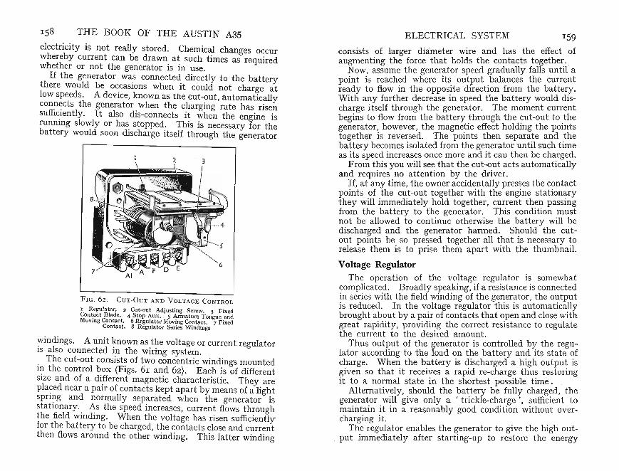
IS8 THE BOOK OF THE AUSTI N A3S
electricity is not really stored. Chemical changes occurwhereby current can be drawn at such times as requiredwhether or not the generator is in use.
If the generator was connected directly to the batterythere would be oc.casions when it could not charge atlow speeds . A device, known as the cut-out, automaticallyconn~cts the generator. when the charging ra te has risensuffi~Iently. It also dis-connects it when the engine isrunmng slowly or has stopped. This is necessary for thebattery would soon discharge itself through the generator
F IG. 62. - CUT . OUT A ND VOLTAGE C ON TROL
I Regulator. 2 Cut-out Adjusting Screw. 3 FixedContac t Blade . 4 Stop Ann. 5 Arm ature Tongue andMovmg Contact. 6 Regula tor Moving Contact. 7 Fixed
Contact. 8 Regulator Series Windings
windings, A unit known as the voltage or current regulatorIS also connected in the wiring system.. The cut-out consist~ of two concentric windings mountedm the cont rol box (FIgS. 6I and 62). Each is of differentsize and of a different magnetic characteristic. They arepla~ed near a pal l' of contacts kept apart by means of a lightspn~g and normally separated when the generator isstationary.. ~s the speed increases, current flows throughthe field winding. When the voltage has risen sufficient ly'for th e battery to be charged, the contacts close and currentthen flows around the other winding. This latter winding
ELECTRICAL SYSTEM IS9
consists of larger diameter wire and has the effect ofaugmenting the force that holds the contacts together. .
Now, assume the generator speed gradually falls until apoint is reached where its output balances the currentready to flow in the opposite direction from the battery .With any further decrease in speed the battery would discharge it self through the generator. The moment currentbegins to flow from the battery through the cut-out to thegenerator, however , the magnetic effect holding the pointstogether is reversed. The points then separate and thebattery becomes isolated from the generator until such timeas its speed increases once more and it can then be charged.
From this you will see that the cut-out acts automaticallyand requires no attention by the driver.
If, at any time, the owner accidentally presses the contactpoints of the cut-out t ogether with the engine station~ry
they will immediately hold together, current then passmgfrom the battery t o the generator. This condition mustnot be allowed to continue otherwise the battery will bedischarged and the generator harmed. Should the cutout points be so pressed together all that is necessary torelease them is to prise them apart with the thumbnail.
Voltage RegulatorThe operat ion of the voltage regulat or is somewha t
complicated. Broadly speaking, if a resistance is connectedin series with the field winding of the genera tor, the outputis reduced. In the voltage regulator this is automaticallybrought about by a pair of contacts that open and close withgreat rapidity, providing the correct resistance to regulatethe current to the desired amount.
Thus output of the generator is cont rolled by the regulator according to the load on the battery and its state ofcharge. When the battery is discharged a high outp ut isgiven so that it receives a rapid re-charge thus restoringit to a normal state in the shortest possible time.
Alternatively, should the battery be fully charged, thegenerator will give only a ' trickle-charge', sufficient t omaintain it in a reasonably good condi tion without overcharging it.
The regulator enables the generator to give the high output immediate ly after starting-up to restore the energy

160 THE BOOK OF THE AUSTIN A3S ELECTRICAL SYSTEM 161taken from the battery. After about 30 minutes' running,the output of the generator is decreased to ..the steadynormal rate of charging.
The regulator unit is extremely reliable and, in fact, issealed by the makers. It should never be altered by theowner. Should it be necessar y at any time to adjust it ,accurate inst ruments are required as well as detailed knowledge of its construction. In your own interest you will bewell advised to let your Aust in dealer attend to it in case ofneed, or take it to a Lucas Serv ice Station.
Generator
The generator is of the plain two-brush, two-pole, shunttype, its characteristics being a rising voltage with anincrease in speed. It consist s of an armat ure with commutator, field-magnet system housed in a yoke (cylin dricalframe), and brush gear (Fig. 63). Arma ture shaft is supported in a ball-race carri ed in driving-end bracket an d aplain bearing in commutator-end bracket .
F I G . 6 3 ·- T HE G E NE R ATOR I N EXPLO DED F ORM
1. Bru sh aud 2 Spr ing. 3 T hr ust Collar . ' 4 Commutator. 5 Field Coil . 6 DistanceCollar. 7 Driving End-bracket . 8 Yoke. 9 Arm ature. 1 0 Field Terminal, 1 3 Nu ts
and Washer . II Brush H older . 12 Commutator Eud-bracke t. 1 4 Terminal
Vent ilation is pro vided by circulat ing air with fan bladesincorpora ted in a pulley driven by V-section belt fromcranksha ft pulley .
The rotation of the arm ature in magnetic field producedindu ces alte rnating volt ages in armature ·windings. Theseare converted into dir ect current to be collected by twocarbon brushes pressed into cont act and passed to battery forstorage.
Output depends on st rength of magnetic. fi~ld and speedat which armature rotates. As any variation of speedcauses a change of output , and since the genera tor is drivenat varying speeds, it is necessary to provide means to control output. This is done by varying the strength of themagnetic field, current value being cont rolled by voltageregulator as already described.
Testing the Generator
The only rotating part in the generat ?r is the. armatu:e.This is a drum-shaped spindle wound WIth a senes of coils,the ends of which are connected to a number of coppercontacts in circular form and known as the commutator.All current generated in the arm ature is collected from thecommuta tor by two carbon brushes. Th ese are pres~ed
into contact with it and lead the current to the electn calsystem. .
It sometimes happens that the generator WIll not chargeeven aft er the commutator has been cleaned (see page 164).Consequently, the anxious owner will ~onder where the faultreally lies. This is where a test lamp ISof help. (See page192, • Fault-finding and Testing '.)
Disconnect the two terminals from the generator, theyellow wire being connected to the main brush tem:inaland the yellow with green tracer to the field termmal.The terminals are of different size to ensure correct replacement. (See page 1 92 for instructions regarding co~ect
refitting.) Temporarily connect together the two termmalson the generater, ear th one wire of the test lead and connectthe other to th ese two br idged terminals. Use a bulb of atleast 36 watts for this test.
Start the engine and then very gradually increase thespeed, when the lamp should light and its brillia~ce increasewith rise in speed. As the generator output IS not controlled when thus connected, take care not to burn out thelamp. If the lamp lights brightly _then the ~enerator isin order, but if only a dim light can be obtained at anyspeed then there is probably some fault in the windings andyou should let your Austin dealer handle it s repair for you.

162 THE BOOK OF THE AUSTIN A3S ELECTRICAL SYSTEM
MaintenanceIt has already been stated that the only moving part
in the generator is the armature that rotates on two bearings. The front bearing is packed with grease at theWorks and requires no further attention. The rear bearingis a porous bronze bush. The lubricator provided forthis bearing consists of a felt pad pressed into contact with'the bush by a light spring. At the rear of the bearing in thecentre, is a small hole into which a few drops of S.A.E.30engine oil should be inserted every 6,000 miles. Do notover-oil, however, for excess lubricant may find its way tothe commutator causing the brushes to stick, and then thegenerator may fail to charge (Fig. 96).
If generator refuses to cut in-:-a fault indicated byignition warning lamp remainin g , on '-the fault may bewith the commutator and brushes. It will be necessary toremov e the generator and partly dismantle it .
Disconnect one terminal of the battery and then disconnect the generator terminal connectors by pulling themout of the locations in which they area push fit.
Loosen the three bolts holding the generator to its bracketand to the adjusting link to allow the fan-belt tension tobe released. Then, remove all three bolts and lift thegenerator away from the engine.
Fully unscrew th e two bolts passing through the generatorbody; when these have been withdrawn the commutatorend-plate can be detached. When -it is removed it willbring with it the two brushes in their mounting brackets.Take care not to lose the distance-washers fitted on thearmature shaft between the commutator and the bush inthe end-plate.
The commutator surface should be bright. If it is not,it should be cleaned. Before doing so it is as well to seeif the two brushes are quite free in their holders, for if theystick the commutator begins to ' burn' due to the sparkingthat takes place.
Test the brushes by gently pulling the flexible connectorsfitted on each. It should be possible to pull them backagainst the spring tension and on releasing them they shouldreturn (Fig. 64). If they feel stiff, draw them carefully outof their holders using a piece of bent wire in the form of a
hook to hold the spring clear of the brush. Wipe them witha petrol-damped cloth.
If the commutator is dirty it may be cleaned with glasspaper. Do not use emery cloth.
When all dirt has been removed refit the brushes so theyare the same way round as originally. They' bed in' to thecommutator and if replaced half a turn round relative totheir holders they will not make efficient contact until somedistance has been covered.
F IG. 64.-GENERATOR BRUSH GEAR
Temporarily raise the brushes sufficiently in their holdersotherwise they may foul the commutator when the endplate is refitted. The brushes may be wedged most conveniently for the purpose by engaging the springs with theirsides. .
After ensuring that any washers originally fitted on thearm ature shaft are in place, enter the end-plate on to theshaft so that the generator mounting-bracket holes are inline. As the two through-bolt holes are drilled on thediameter, the end-plate could be refitt ed half a turn out.
When the commutator has entered between the two

THE BOOK OF THE AUSTIN A3S ELECTRICAL SYSTEM 165brushes fit the spr ings on top of each brush in the normalmanner, push the end-plate right home and secure it withthe two bolts.
Reassemble the generator to the engine taking care toinstall the fan-be lt over the pulley and to adjust its tensionbefore finally tightening the bracket-mounting bolts .
Rep lace the two terminal connec tors and refit thebattery cable connection.
The generator should now charge satisfactorily.If there are signs that the commutator is blackened and
despite cleaning, as described above, st ill will not charge itis best to have it checked by your Austin dealer.
BatteryThe battery, one of the most important components on
any car, is composed of six cells each of 2 voltsand connected together by lead straps so that it builds up into arz-volt unit. Each cell contains positive and negativeplates immersed in a solution of sulphuric acid and distilledwater known as the electrolyte. The plates are dividedby insulator separators (Fig. 65).
FIG . 65 .- LUCAS 12-VOLT BATTERY
Should the battery be removed at any time it is importantthat the terminals are correctly reconnected. The terminalposts are of different.sizes and are usually marked + and
. It will be found that the posit ive post (the former)is slightly larger than the negative, to prevent any incorrectconnection on replacement. A battery can be ruined byconnecting the positive cable to the negative terminal.
There is a tendency to neglect battery maintenanceprobably because • it mus t be all right for it is working' .
The prime necessity is to add distilled water to the six
FIG. 66.- TESTI NG SPECIFIC GRAVITY
I Specific Gravi ty Reading. 2 See th at F loat is clear ofTube
cells at least every month. Tap water should not beused for • topping up' for it contains iron and certaindetrimental salts . A supply of distilled water sufficient fora year's attention can be obtained for a shilling or two,therefore do not be tempted to ruin an expensive battery.Buy a bottle of distilled water from your chemist or servicestation and keep it in the garage for regular use.
A useful accessory is a hydrometer specially calibratedfor car-battery use and obtainable through your usualstockist (Fig. 66). It serves two purposes-to add wat erto the individual cells-so preventing spilling liquid on thecell tops- and to ascertain if the specific gravi ty of theelectrolyte is correct.
I66 THE BOOK OF THE AUSTIN A3S ELECTRICAL SYSTEM
Consider first the question of liquid on top of the cells.Never allow the tops of the cells to be wet. Remember thatsulphuric acid in the electrolyte will attack metal. Consequent ly, if the battery is over-filled the terminals willcorrode and the battery tray will be eaten away.
The normal specific gravity of a charged battery isapproximately I 'z80 to I '300 but as it becomes dischargedthe gravity can fall to I'IOO, when it is practically , flatout '.
Checking the gravity is not difficult. Unscrew the fillercap, insert the hydrometer and draw some of the elect rolyteinto the glass tube by compressing and releasing the rubberbulb. Allow the float to be freely suspended (z, Fig. 66)but make sure it is clear of the sides of the glass tube.Then not e the figure that is level with the liquid; this isthe specific gravity reading. It is important to ensure thatthe reading of each cell is approximately equal; alsothat the level in each cell is the same.
If one cell has a lower reading than the others, it can becorrected by drawing off as much fluid as possible andadding sulphur ic acid of I '350 s.g. If the cell cannot becorrected by several such additions it may be that thereis a short -circuit and the battery should be t ested by yourAustin dealer or local Lucas service station.
Similarly, if one cell appears to require topping up morefrequently than any of the others, examine the batterycase for it may be that there is a crack through which th eelectrolyte is leaking away.
The routine maintenance required is given below butthere is another point that should be mentioned. This isto make sure the battery is not allowed to become loosein its container. Do not overtighten the securing clamps,however, for the case may be cracked by so doing. On theother hand, if it is not sufficiently t ight the case may moveand chafe and possibly damage the cable insulation .
MaintenanceUnscrew the cell plugs monthly and examine the electro
lyte level. Top up if necessary, as instructed above.N ever hold a lighted match over the cell tops to ascertain
the level. The gases given off by a charged battery are inflammable and can explode-in some cases they have
blown out the cell tops and caused injury to the unfortunate person who received the acid in his face. If youhave no inspection lamp use a torch, although the batteryis very accessibly mounted beneath the bonnet .
The electro lyte should be level with the top edge of theseparators. Do not be tempted to ' save topping up nextmonth ' by putting in too much distilled water for whenthe battery , gasses ' the level rises. If the cells are overfilled the surp lus will find its way into the battery compartment , rusting and corroding everything it touches. , ,
Never add anything but distilled water unless It ISnecessary to correct the gravity, by adding acid as describedabove . With normal gassing the electrolyte merely becomes more concentrated but is restored to normal by theaddition of distilled water. Adding acid will progressivelyst rengthen the acid solution and becomes increasinglyharmful to the plates.
When checking the level in the cells you may find thatno liquid is visible. In thi s case, insp~ct at. more frequentintervals for it may be that the car IS bemg used to anextent that causes a greater-than-usual electrolyte loss.
Partly dry cells become damaged for two reasons : (a)the paste of which the plates are formed t ends to becomedislodged unless covered with acid; and (b) only the areaact ually immersed in acid is capable of,being charged. !hus,if the cell is half empty the chargmg rate automaticallybecomes doubled , and this is not good for the plates.
Keep the positive and negative terminals clean andprotected from corrosion with a film of petroleum jelly.If necessary, disconnect the terminals, and clean the. postsand the insides of the ter minal clamps. Securely t ightenthe bolts after replacement. As a very heavy current istaken by the starter motor, dirty terminals prevent itoperating efficiently . See that the earth connection fromthe positive terminals to the chassis is clean and that thebolt is tight . .
Owners sometimes wonder if frost can damage theirbatteries should the electrolyte freeze. In England, afully-charged battery with electrolyte of the correctgravity will not be affected by the severest frost. Incases where the battery is fully- or nearly fully- disch argedand where the frost is severe, it is possible for the
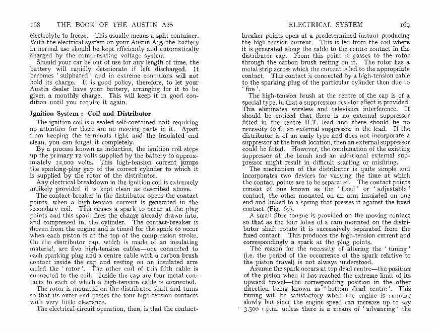
168 THE BOOK OF THE AUSTIN A3S ELECTRICAL SYSTEM 169electrolyte to freeze. This usually means a split container.Wit h the electrical syst em on your Austin A35 the batteryin normal use should be kept efficiently and automaticallycharged by the compensating voltage system.
Should your car be out of use for any length of time, theba ttery will rapidly deteriorate if left discharged. Itbecomes 'sulphated' and in extre me conditions will nothold its charge. It is good policy, therefore, to let yourAustin dealer have your battery, arranging for it to begiven a monthly charge. This will keep it in good condition until you require it again.
Ignition System: Coil and DistributorThe ignition coil is a sealed self-contained unit requiring
no attention for there are no moving parts in it. Apartfrom keeping the terminals tight and the insulated endclean, you can forget it completely.
By a process known as induction, the ignition coil stepsup the primary 12 volt s supplied by the battery to approximat ely 12,000 volts. This high-tension cur rent, jumpsthe sparking-plug gap of the correct cylinder to which itis supp lied by the rotor of the dist ributor.
Any electrical breakdown in the igni tion coil is ext remelyunlikely provided it is kept clean as described above.
The contact-breaker in the distributor opens the contactpoints, when a high-tension current is generated in thesecondary coil. This causes a spark to occur at the plugpoint s and this spark fires the charge already drawn into,and compressed in , the cylinder. The contact-breaker isdrive n from the engine and is timed for the spark to occurwhen each piston is at the top of the compression stroke.On the distributor cap, which is made of an insulat ingmaterial, are five high-tension cables-one connected toach sparking plug and a centre cable with a carbon brushontact inside the cap and resting on an insulated armall d the 'rotor' . The other end of this fifth cable is
connected to the coil. Inside the cap are four metal contacts to each of which a high-tension cable is connected.
The rotor is mounted on th e distributor shaft and turnsso that it s outer end passes the four high-tension contactswith very little clearance.
The elect rical-circuit operation, then, is that the contact-
breaker points open at a predete rmined instant producingthe high-tension.current. This is led from the coil whereit is generated along the cable to the centre contact in thedistribu tor cap. From this point it passes t o the rotorthrough the carbon brush resting on it. The rotor has ametal st rip across which th e current is led to th e appropriatecontact. This contact is connected by a high -tension cable~o th~ sparking plug of the particular cylinder then due to
fire .The high-tension brush at the centre of the cap is of a
special type, in that a suppression resistor effect is provided.This eliminates wireless and television interference. Itshould be noticed that there is no external suppressorfitted in the centre H.T. lead and th ere should be nonecessity to fit an external suppressor in the lead. If thedistributor is of an early type and does not incorporate asupp ressor at the brush location, then an external suppressorcould be fitted. However, the combination of the existingsuppressor at the brush and an additional externa l suppressor might result in difficult starting or misfiring.
The mechanism of the distributor is quite simple andincorporates two devices for var ying the t ime at whichthe contact points are to be separated. The contact pointsconsist of one known as the 'fixed' or ' adjustable 'contact, the other mounted on an arm insulat ed on oneend and linked to a spring that presses it against the fixedcontact (Fig. 67).
A small fibre tongue is provided on the moving contactso that as the four lobes of a cam mounted on the dist ributor shaft rotate it is successively separated from thefixed contact. Thi s produces the high-tension current andcorrespondingly a spark at the plug points.
The reason for the necessity of alte ring the 'timing '(i.e. the period of the occurrence of the spark relative tothe piston travel) is not always understood.
Assume the spark occurs at top dead centre-the positionof the piston when it has reached the extreme limit of itsupward travel-the corresponding position in the otherdirect ion being known as 'bottom dead centre ' . Thistiming will be satisfactory when th e engine is runningslowly but since the engine speed can increase up to say3,500 r.p.m . unless there is a means of ' advancing' the

FIG. 67.-DISTRIBUTOR TYPE DMzPH4A Contact Poin ts . B Condenser. C Contac t Adjus ting Screws. D Micrometer
Adjnst er . E . Cam and Drive-shaf t Oiling Point
t iming, the piston would be so far down its stroke atthe greater r.p.m. that much power would be lost beforethe mixture has fully ignited. Accord ingly, an ingeniousdevice, known as the centrifugal advance mech anism, isincorporated so th at with increase in engine speed thespark au tomat ically is made t o occur earlier. In actualfact, with the engine running fast the spark occurs considerably before the pistons have reached top dead centre.Owing to the limited time available, however, the mixture
THE BOOK OF THE AUSTIN A3S ELECTRICAL SYSTEM 171
is not -fully ignited and therefore is not ready to do usefulwork until the pistons just commence to descend, thusensuring efficient operation.
The advance mechanism consists of two spring-loadedweights normally held inwards. As engine speed increasesthey tend to fly outwards and this tendency is utilized bylinking them to the distributor shaft so that it turns relativeto it s driving shaft and advances the ignition.
At first sight this arrangement would appear ideal. Butso anxious a re the designers to obtain thoroughly efficientoperation that they have incorporated a vacuum timingcontrol. Under conditions of sudden acceleration fromrelatively slow engine speeds there may be a tendency forthe ignition suddenly to advance due to the change ofdepression in the manifold . The vacuum timing contro l,work ing off this depression, controls the speed of ignitionadvancement in relation to the throttle opening until thedepression is constant. Directly the engine speed hasrisen sufficiently, the timing control provides the correctrange of advance.
There is one other important component in the distributor known as the condenser but this is a self-containedunit havin g no moving parts. It is electrically connectedin parallel with the contact points and reduces any sparkingthat otherwise would occur and could soon burn the points.
MaintenanceAs with all other mechanisms, the distributor requires
regular lubrication. It is provided with suitable lubricatorsand the slight attention req uired is easily carried out.
Every 1,000 miles remove the distributor cap , by springingaside the two retaining clips. Take off the rotor arm.Apply two or three drops of thin machine oil adjacent tothe head of the screw inside the mounting carrying therotor. A small passage is provided to conduct the lubricant to the surfaces needing it (Fig . 68). Smear the camlobes with a film of petroleum jelly . .Do not apply anexcess otherwise it will be flung off the cam when theengine is running and may reach the contact points. Oilor grease on the contact points is detrimental and maycause erratic running or even complete failure.
Since the spark has to be delivered to the correct cylinder,
DcB
170

172 THE BOOK OF THE AUSTIN A35
when replacing the rotor note that there is a register toensure.it is replaced correctly. Due to its specially-designedshape the cap cannot be replaced incorrectly.
Lubricate the spindle on which the moving contact armis mounted. The contact-breaker arm must be raised to
FIG. 68.-0ILING DISTRIBUTOR
A Connection from Coil to Contact-breaker. BB PointsAdjustm ent Screws. C Condenser. D Contact-breakerPoints. E Micrometer Adjuster. F Vacuum Pipe Union
allow grease to be applied but do not finger the contactpoint or allow grease to reach it. ,
The moving contact may be freed by first unscre:vingthe nut holding the low-tension cable to the terminal.Loosen nut adjacent to insulated collar and slotted end ofspring may then be detached from bolt.
When replacing the lightly greased contact on its pivot ,insert th e slotted end of the spring between the squared .end of the bolt and the insulator . Tighten the nut andcheck that the spring and contact are correctly aligned.The flat insulated washer fitted beneath the contact onth e pivot must not be omitted.
The distributor mechanism should be lubricated. Accessis obtained through a small hole drilled in the base. Lubricate sparingly, but avoid excess oiling.
Replacing the Plug LeadsIf the plug leads are removed at any time, and if they
ELECTRICAL SYSTEM 173
are not numbered or marked to ensure correct replacement,proceed as. follows: ,.
Unscrew the sparking plug from No. I cylinder (i.e.that nearest the radiator). Press the thumb over the holeand turn the engine by the starting handle until you feelair blowing past your thumb. This shows that the pistonis rising on the compression stroke.
Another method of ascertaining approximately top deadcentre position on No. I cylinder compression stroke, is toremove the valve-chamber cover. Move the engine nearlyhalf a turn after the inlet valve has closed. The inletvalve for No. I cylinder is No.2 from the front.
To establish the exact position of the piston, insert astiff piece of wire in the sparking-plug hole and slowlyturn the engine. The wire, suitably bent to rest on thetop of the piston, will indicate when the piston is at itstopmost position.
With the engine set by either method, approximatelyon top dead centre firing position on No. I cylinder, proceedas follows.
Remove the distributor cap and ascertain to whichcontact /the rotor arm is pointing. Replace the distributorcap , noting the terminal socket concerned. Insert theplug leadconnecting No. I cylinder to th is terminal socket.Follow around the distributor cap in an anti-clockwisedirection, looking down on top of the cover, and insertthe plug lead for No. 3 cylinder. Next to this, againmoving in an anti-clockwise direction, fit NO.4 plug lead.Lastly, fit the lead to No. 2 cylinder. Since the rotorturns in an anti-clockwise direction it will be realized thatthe firing order is I, 3, 4 and 2.
If th~ distributor has been :emov~d, re-time by turningthe engine so that No. I cyhnder IS on the compressionst roke. (The method of doing this is described at the topof previous page.)
Next , check that the contact-point gap is correct. Ifnot , reset as described above.Wit~ the rotor J?ointing towards No. I cylinder contact,
the points should Just be about to open. If this is not soloosen the clamp bolt, which is on the same side as thestarter motor, so that the distributor body can be turned toobtain this setting. Lock the clamp bolt securely when set.

FIG. 7o.-TRIMMING-UP CONTACT POINTS
To adjust contact-breaker points turn engine over untilcontacts are fully open. Then slacken screw (1) and insertscrewdriver in slot (2). Move plate until gap betweencontacts is '014 to '016 in. ('356 to '406 mm.) . Whenset t ing is correct, tighten locking screw and re-check gaps.
The contact-breaker points should be cleaned every6,000 miles. It may be found that they have become dirtyor have worn unequally-usually one develops a peak; theother a corresponding hollow. The most satisfactory wayto correct this unevenness is to remove the contacts,loosening both terminal nuts on the bolt that holds thecontact spring . The spring may then be disconnectedfrom the bolt-the end is slotted- and the contact drawnoff its pivot. Take care not to lose the flat insulatedwasher fitted on the pivot between the moving contact andthe base. If required, the other contact can be removedby unscrewing its two adj acent screws and lifting it awayfrom the base .
To restore the points to their original condition use eithera fine carborundum stone (Fig. 70) or one of the special
175ELECTRICAL SYSTEM
4
FIG. 6 9 .-D I ST RI BU T OR AS FITTED TO LA TER MODELS
I Control AdjustingScrew and 2 Slot. 3 Cam and Drive ShaftOiling Points. 4 Contact Points. 5 Micrometer Adjustment
174 THE BOOK OF THE AUSTIN A3S
The outside, as well as the inside, of the distributorcap should be kept clean. An accumulation of dustand dirt can cause short-circuits particularly when .theweather is wet. The high-tension current then leaks awayto earth without causing sparking at the plug points. Forthe same reason, wipe the leads as well as the plug insulators.
Adjustments . tCheck the contact-breaker gap every 5,000 miles. .This is quite simply done by removing the distributor c~p
and turning the engine with the start ing handle until any oneof the lobes of the cam has fully separated the contactpoints. The gap, which should be '014 to '016 in . ('356 to'406 mm.), may be checked by using the appropriate feelergauge provided in .the tool kit .
Carefully inserted, the gauge should exactly slide betweenthe gap. If the gap is too wide- or if it is too narrowreadjust by loosening the two screws in the base plate.When these are loosened, the adjustable contact may bemoved nearer to or away from the other. In case theadjustment has become alt ered when the screws weretightened, recheck and correct if necessary.
Modification to DistributorOn later models a modified distributor is fitted (Fig. 69).
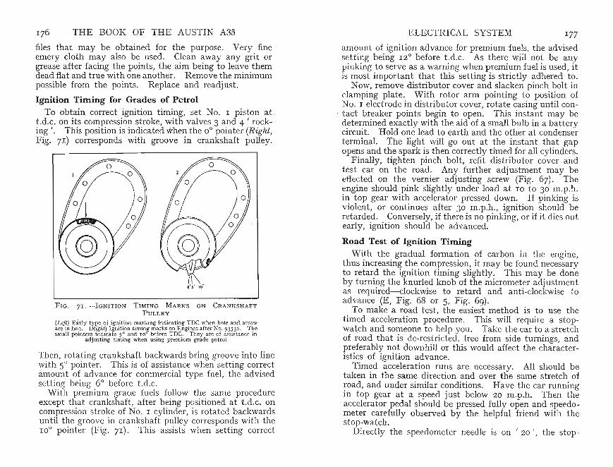
amount of ignition advance for premium fuels, the advisedsetting being 12° before t.d.c. As there will not be anypinking to serve as a warning when premium fuel is used, itis most important that this setting is strictly adhered to .
Now, remove distributor cover and slacken pinch bolt inclamping plate. With rotor arm pointing t o position ofNO.1 electrode in distributor cover, rotate casing until contact breaker points begin to open. This instant may bedetermined exactly with the aid of a small bulb in a batterycircuit. Hold one lead to earth and the other at condenserterminal. The light will go out at the instant that gapopens and the spark is then correctly timed for all cylinders.
Finally, tighten pinch bolt, refit distributor cover andtest car on the road. Any further adjustment may beeffected on the vernier adjusting screw (Fig. 67). Theengine should pink slightly under load at 10 to 30 m.p.h.in top gear with accelera tor pressed down. If pinking isviolent, or continues after 30 m.p.h., ignition should beretarded. Conversely, if there is no pinking, or if it dies outearly, ignition should be advanced.
Road Test of Ignition TimingWith the gradual formation of carbon in the engine,
thus increasing the compression, it may be found necessaryto retard the ignition timing slightly. This may be doneby turning the knurled knob of the micrometer adjustmentas required-clockwise to retard and anti-clockwise toadvance (E, Fig . 68 or S, Fig. 69).
To make a road test , the easiest method is to use thetimed acceleration procedure. This will require a stopwatch and someone to help you. Take the car t o a stretchof road that is de-restricted, free from side turnings, andpreferably not downhill or this would affect the characteristics of ignition advance.
Timed acceleration runs are necessary. All should betaken in the same direction and over the same stretch ofroad, and under similar conditions. Have the car runningin top gear at a speed just below 20 m.p .h. Then theaccelerator pedal should be pressed fully open and speedometer carefully observed by the helpful friend with thestop-watch.
Directly the speedometer needle is on ' 20 ', the stop-
176 THE BOOK OF THE AUSTIN A3S
files that may be obtained for the purpose. Very fineemery cloth may also be used. Clean away any grit orgrease aft er facing the points, the aim being to leave themdead flat and true with one another. Remove the minimumpossible from the points. Replace and readjust.
Ignition Timing for Grades of PetrolTo obtain correct ignition timing, set No. 1 piston at
t.d. c. on its compression stroke, with valves 3 and 4 • rocking '. This position is indicated when the 0° pointe r (Right,Fig. 71) corresponds with groove in crankshaft pulley.
F IG. 7 I.-IGNI TION TIMING MARKS ON CRANKSHAFTPUL LEY
(L ef t ) E arl y type of ignition marking indi cating TD C when hole and arroware in line. (Rig ht) Igni tion timing marks on Engines after No. 93~36 . Th esmall point ers indica te S O and 10° before TD C. They are of assista nce in
adjusting timing when using premium grade petrol
Then, rotating crankshaft backwards bring groove into linewith SOpointer . This is of assistance when setting correctamount of ad vance for commercial type fuel, the advisedsetting being 6° before t. d.c.
With premium grade fuels follow the same procedureexcept that crankshaft , after being positioned at t .d .c. oncompression st roke of NO. 1 cylinder, is rotated backwardsuntil the groove in crankshaft pull ey corresponds with the10° pointer (Fig. 71). This assists when setting corr ect
ELECTRICAL SYSTEM I77

178 THE BOOK OF THE AUSTIN A35 ELECTRICAL SYSTEM 179
watch should be started. and stopped at an agreed maximum speed-i.e. 50 or 60 m.p.h. Under the whole of thispart of the test the accelerator must be fully open.
On achieving the desired maximum speed reading on thespeedometer stop the stop-watch . Note the time asaccurately as possible. Go back and repeat this test withth e ignition advanced a little more. If the recorded t imeis less than previously, continue testing and advancing theignition until no improvement in acceleration time isobtained.
Obviou sly, if the ignition is further advanc ed but thetime taken to accelerate betw een the set figures increases,it mean s that the engine is over- advanced and is not givingits maximum performance.
It is not necessary to time up to speeds of 50 or 60 m.p.h .Some drivers- particularly those who own a new car- maywish to restrict road speeds. Accordingly, accelera tiont imes may be taken between 20 and 30 m.p.h. No doubtthis will commend it self within areas restricted by speedlimits. The important point t o observe is that whentesting between 20 and 30 m.p.h., the' stop ' and' start 'times must be t aken with great accur acy. When testingup to say 60 m .p.h. an error of a second will not proportionately affect the result so much as it would do when testingup to 30 m.p.h. where it could represent a large proportionof the time involved.
If by this method the car is set to run on standard fuelthen it will run equally well on a premium-grade fuel, butthe additional benefit the better-grade fuel can conferwill not be obtained. The moral is, of course, to reset theignition so that the premium-grade fuel may be utilizedto the best advantage.
Conversely , if the car has been set to use a premiumgrade fuel, but a standard grade fuel is constantly used,the engine will probably be rather over-advanced andshould be reset or somewhat harsh and possibly inefficientperformance will result.
Sparking PlugsAlthough an insignificant accessory to look at , the spark
ingplug is most important . Plugs have to operate underhigh temperat ures, mu st be of suitable reach for the plug
points to be in the best position for igni ting the mixture,and must not be so cool as to permit oil to collect on themor so hot as to cause pre-ignition. Obviously, the corre cttype of plug is necessary and you will be well advised touse the type recommended by the Austin Motor Co. Ltd.This is the Champion N5. long-reach typ e.
No plug has an indefinit e life and on an efficient engine,particularly when it is not a large one, the owner is welladvised to consider renewing plugs that have exceeded10,000 miles. Often err atic running and bad starting canbe traced to plugs, the useful life of which has been exceeded.
Periodically remove the plugs at least every 6,000 milesand clean the points of any carbon by brushing them witha type of brush known as a ' file card'. Should the plugshave to be clean ed intern ally, this is most easily doneby washing them out thoroughly in petrol. If they donot respond to this treatment let your Aust in dealer cleanthem for you on his sand-blast . This will only cost you .a few pence and the points can be set , t est ed under pressur e,and a report given on their condition.
Rememb er that a plug is vulnerable and can be damagedby over-tightening or by accidentally hitting the insulator.Finally, do not be tempted to use plugs without theirgaskets . You cannot get a perfect seal and not only willcompression be lost but also there will be an air leak sothat the mixture will be upset on the induction stroke .
Plug AdjustmentHaving cleaned the plugs, t est the gap at the points.
The gap should be '025 in. (,64 mm.) (A, Fig. 72). The pluggap is very important and any wide variation as betweenthe four plugs on the engine can make even slow runningimpossible.
If it is necessary to adjust the gap, never bend the centreelectrode. If the gap must be adjust ed, bend the elect rodefitted to the plug body. Many plugs have been ruinedby owners bending the centre electrode resulting in eitherloosening it in the insulator or cracking the insulatorIn either case the plug soon becomes faulty .
Alwayskeep the plng insulators, the leads, and the distributor cap free from dust an d dirt. In damp weathermoi sture can collect on this film of dust making starting

180 THE · BOOK OF THE AUSTIN A3S ELECTRICAL SYSTEM 181
FIG. 7 2 .-ADJUSTING PLUG GAP
The gap at inset A Top left should be .025 in.
difficult because the high-tension current tends to shortcircuit to earth rather than spark at the plug points.
Tracing Ignition TroublesIf the ignition is carefully maintained, as describ ed in
the preceding pages, you should have no unforeseen delaysdue to breakdown. But as any complicated piece ofmechanism is liable to develop some slight defect it maybe well to consider what minor difficulties may arise andhow to correct them.
Ignition trouble usually falls under two heads: completestoppage or intermittent firing.
Suppose the car, otherwise running perfectly, suddenlystops. The following test should indicate th e quickest wayof finding where the trouble lies.
Leaving the ignition switched on, disconnect the low-
tension cable at the side of the distributor. Touch thebare metal of the cylinder block with it, when sparksshould be seen. If you cannot get any sign of current onthis wire there may be a dirty or loose conn ection or, indeed, a broken wire that will have to be located. Testthe low-tension circuit generally by seeing if the headlamps will light.
If current is reaching the low-tension feed, reconnect itand make sure the rocker arm is free to move. It is rarefor it to stick but it may have stuck open. If so, removethe arm, clean the bush inside, lightly oil its pivot andreplace it. If the arm is free, check the gap, adjustingif necessary. See that the points are clean and flat.
If the points are in order, disconnect the centre wirefrom the distributor cap and hold it about i in. from thecylinder block. With the points normally touchingseparate them by pressing them apart. This should causea spark from the high-tension cable to the block. If nospark is forthcoming then the coil is probably at fault.
If a spark is produced, refit the cable to the cap, replacethe cap and test the sparking-plug leads by turning theengine and holding them one at a time about 1 in. fromthe cylind er block. Should no spark be visible from any,then there may be a short-circuit in the rotor or distributorcap.
Misfiring is not always easy to trace being generallydue to some condition such as dirty contact points, weakspring, stiff rocker-arm action, short-circuiting due to dirton the distributor cap or rotor, sticking valves, obstructedpetrol supply, or carburettor misadjustment.
A broken wire is not always easy to trace owing to manybeing bound together in the looms. If found and accessible,obviously a temporary repair may be made by baring theends of the wire and twisting them together. But, insuch a case, as the system is an ' earth return' do protectthe joint with insulation tape.
Additional causes are loose wires and connections ordirty and maladjusted plugs. Normally the high-tensioncables, although well protected, might develop a shortcircuit if the insulation has perished. This possibilityshould not be overlooked.
Remove the plugs, clean and test as already suggest ed.
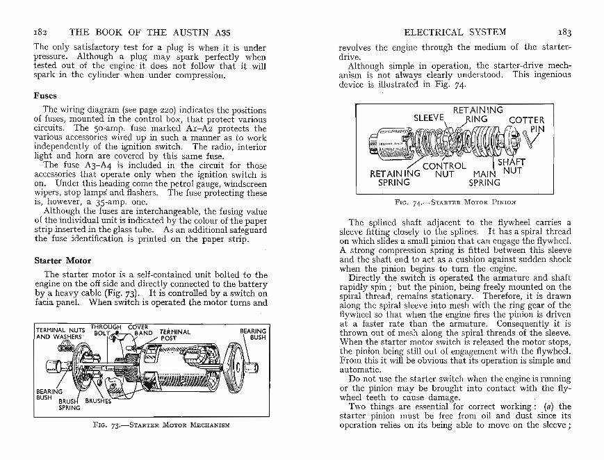
182 THE BOOK OF THE AUSTIN A3S ELECTRICAL SYSTEM
The only satisfactory test for a plug is when it is underpressure . Although a plug may spark perfectly whentested out of the engine it does not follow that it willspark in the cylinder when under compression.
Fuses
The wiring diagram (see page 220) indicates the positionsof fuses, mounted in the control box, that protect variouscircuits. The 50-amp. fuse marked A1-A2 protects thevarious accessories wired up in such a manner as to workindependently of the ignit ion swit ch. The radio, interiorlight and horn are covered by this same fuse.
The fuse A3-A4 is included in the circuit for thoseaccessories that operate only when the ignition switch ison. Under this heading come the petrol gauge, windscreenwipers, stop lamps and flashers. The fuse prot ecting theseis, however, a 35-amp. one.
Although the fuses are interchangeabl e, the fusing valueof the ind ividual unit is indicat ed by the colour of the paperst rip inserted in the glass tube. As an additional safeguardthe fuse ident ificat ion is printed on the paper strip.
Starter Motor
The starter motor is a self-contained unit bolted to theengine on the off side and directly connected to the batteryby a heavy cable (Fig. 73). It is controlled by a swit ch onfacia panel. When switch is operated the motor turns and
FIG. 73.-STARTER MOTOR MECHANISM
revolves the engine through the medium of the st arterdrive.
Although simple in operation, the starter-~riye m~ch~
anism is not always clearly understood. This mgemousdevice is illustrated in Fig . 74.
FIG. 74.- S TART E R MOTOR PINION
The splined shaft ad jacent to the flywheel carries asleeve fitt ing closely to the splines. It has a spiral threadon which slides a small pinion that can engage the flywheel.A strong compression spring is fitt ed between this sleeveand the shaft end to act as a cushion against sudden shockwhen the pinion begins to turn the engine.
Directly the switch is operated the armature and shaftrapidly spin; but the pinion, being freely mounted on thespiral thread, remains stationary. Therefore, it is drawnalong the spiral sleeve into mesh with the ring gear of theflywheelso that when the engine fires the pinion is drivenat a faster rate than the armature. Consequently it ist hrown out of mesh along the spiral threads of the sleeve.Wh en the starter motor switch is released the motor stops,the pinion being still out of engagement with the flywheel.From this it will be obv ious that its operation is simple andautomatic.
Do not use the starter switch when the engine is runningor the pinion may be brought into contact with the flywheel teeth to cause damage.
Two things are essential for correct working : (a) thestarter pinion must be free from oil and dust since itsoperation relies on its being able to move on the sleeve;
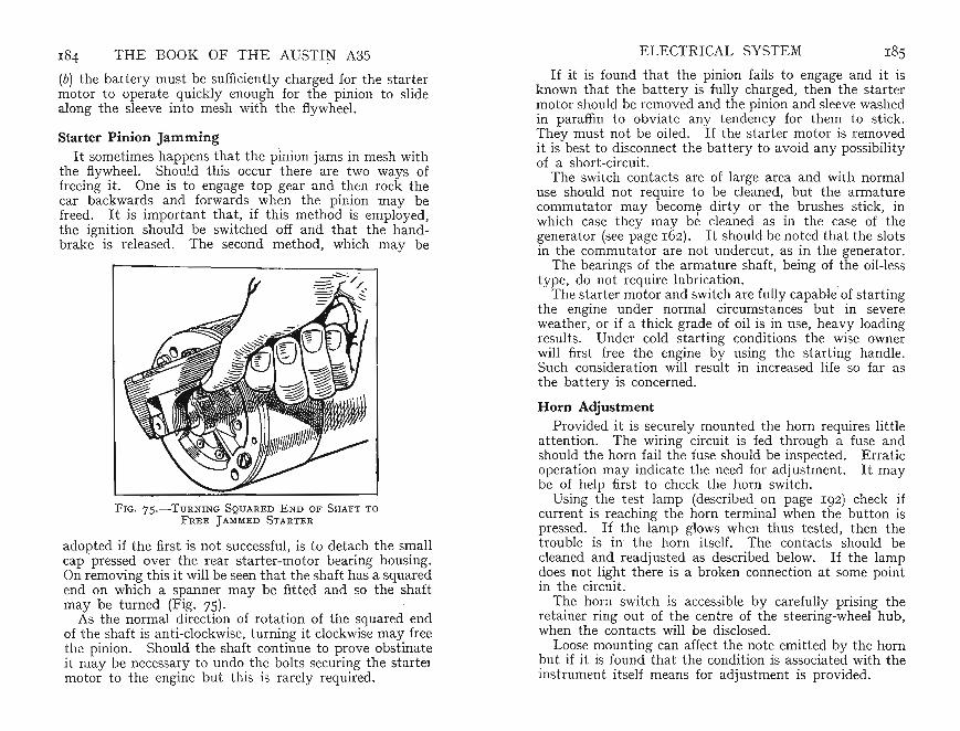
184 THE BOOK OF TH E AUSTIN A3S
(b) the battery must be sufficient ly cha rged for the startermotor to operate quickly enough for the pinion to slidealong the sleeve into mesh with the flywheel.
Starter Pinion JammingIt sometimes happens that the pini on jams in mesh with
the flywheel. Should this occur there are two ways offreeing it. One is to engage top gear and then rock thecar backwards and forward s when the pinion may befreed . It is important th at, if this method is employed,the ignition should be switched off and that the handbrake is released. The second method, which may be
FIG. 75.-TuRNI N G S QU ARED END OF SH AFT T O
FRE E J AMMED STA RTER
adopted if the first is not successful, is to detach the smallcap pressed over the rear starter-mot or bearing housing.On removing this it will be seen that the shaft has a squaredend on which a spanner may be fitted and so the shaftmay be turned (Fig. 7S).
As the norm al dir ection of rotation of the squared endof the sha ft is an ti-clockwise, turning it clockwise may freethe pinion. Should the shaft continue to prove obstinateit may be necessary t o undo the bolts securing the startermotor to the engine but this is rarely required.
ELECTRICAL SYSTEM I8S
If it is found that the pinion fails to engage and it isknown tha t the battery is fully charged, then the startermot or should be removed and the pinion and sleeve washedin paraffin to obv iate any tendency for them to stick.They must not be oiled. If the sta rter motor is removedit is best to disconnect the battery to avo id any possibilityof a shor t -circuit.
The switch contacts are of large area and with normaluse should not require to be cleaned, but the armaturecomm utator may become dirty or the brushes stick, inwhich case they may be cleaned as in th e case of thegenerator (see page 162). It should be not ed that th e slotsin the commuta tor are not undercut , as in the generator.
The bearings of the armature shaft, being of the oil-lesstype, do not require lubrication.
The starter motor and switch are fully capable'of start ingthe engine under normal circumstances but in severeweather, or if a thick grade of oil is in use, heavy loadingresults. Under cold starting conditions the wise ownerwill first free the engine by using the starting handle.Such considera t ion will result in increased life so far asthe battery is concerned.
Horn AdjustmentProvided it is securely mounted the horn requires little
attention. The wiring circuit is fed through a fuse andshould the horn fail the fuse should be inspected. Erraticopera tion may indicate the need for ad just ment. It maybe of help first to check the horn switch.
Using the test lamp (described on page 192) check ifcurrent is reachin g the horn termin al when the button ispressed. If the lamp glows when thus tested, then thetrouble is in the horn itself . The contacts should becleaned and readjusted as describ ed below. If th e lampdoes not light there is a broken connection at some pointin the circuit.T~e ho~n switch is accessible by carefully prising the
ret ainer ring out of the centre of the steering-wheel hub,when the contacts will be disclosed.L~os.e J?ounting can affect the note emitted by the horn
but If It IS found that the condition is associated with theinstrument it self means for adjustment is provided.

186 THE BOOK OF THE AUSTIN A3S
It is best to remove th e fuse when adjusting, for otherwise it may inadvertently be blown should the adjustmentbe screwed down too far. Take care to keep the terminalsof the hom from touching the chassis when disconnectedor a shor t-circuit may result. Adjust ing does not controlthe pitch or note of the horn but is pro vided as a meansof comp ensating for any wear that may arise in use.
First loosen the locknut in the centre rear of the hornbody. Then turn the adjusting serrated screw in an anticlockwise direction so that the contact points are fullyseparated. This can be checked by moving the adj ustmenta little at a time until on pr essing the horn button it willnot sound. Then turn the adjust ing screw six not ches inthe opposit e direction , to bring the contact points closertogether. Secur ely lock t he set ti ng with the locknut.
Lamps and WiringThe wiring is well insulated and firmly held by clips to
prevent it chafing but it is advisable to inspect the variousleads from time to time. Any part of the insulation thatappears to be dam aged should be bound with- insulatingtape. Points where rubbing is somet imes liable to occurare where the cables for the hea dlights and sidelights passunderneath the mudguards to the lamps. If the headlamps or sidelamps flicker take immediate steps to find thereason and put it right . The sudden failure of one or bothheadlamps when you are driving fast at night can be awkward-to say the least .
HeadlampsAs the headlamp bulbs are of the 'pre-focused' type
there is no adj ustment provided for mov ing th e bu lbrelative to the reflector. If the instruct ions are carefullyfollowed the best optical set ting will be obtained.
Double-filam ent bulbs are fitted, these having a cur rentconsump tion of 42 watts in th e stra ight-ahea d posit ion and36 watts when dipped .
Replacing Head and Sidelamp BulbsUndo the securing screw at the bottom of the rim that fit s
around the headl amp glass (Fig. 76). This rim can thenbe removed by lifting it away, det achin g it first at the
ELECTR ICAL SYSTEM 187
bottom an d disclosing a rubber dust excluder. Whenthis has been carefully det ached, the screws controllingthe ' beam direction' will be visible. Do not attempt toturn any of these screws or the adjustment will be affect ed.Adjusting the headl amps is dealt with below:
Press the light unit inwards aga inst the spn ng pressureat the same time turning it to the left, or anti-clockwise.
5F IG. 7 6 .- HEA D LA MP GLASS ASSEMB LY
I Verti cal Adjustment Screw. 2 Rubber Dust Ex cluder . 3 Fron t Rim. 4 R imSecuring Screw. 5 Horizontal Adjusting Screws
This will allow light unit to be removed from the body asthe heads of screws can then pass through th e slotted holes.
All th at is necessar y to gain access to the headlampbulb is to turn the back-shell in an anti-clockwise direction(as viewed from th e back) when it can be drawn off andth e bulb detached from the holder.
Aft er installing the replacement bulb of the requiredtype (as described on page 186) and noting that a registerensures th e bulb taking up it s correct position , refit theback-shell. Take care that th e spring-loaded screws retaining the light unit have their springs behind th e flangeand th eir head s in front.
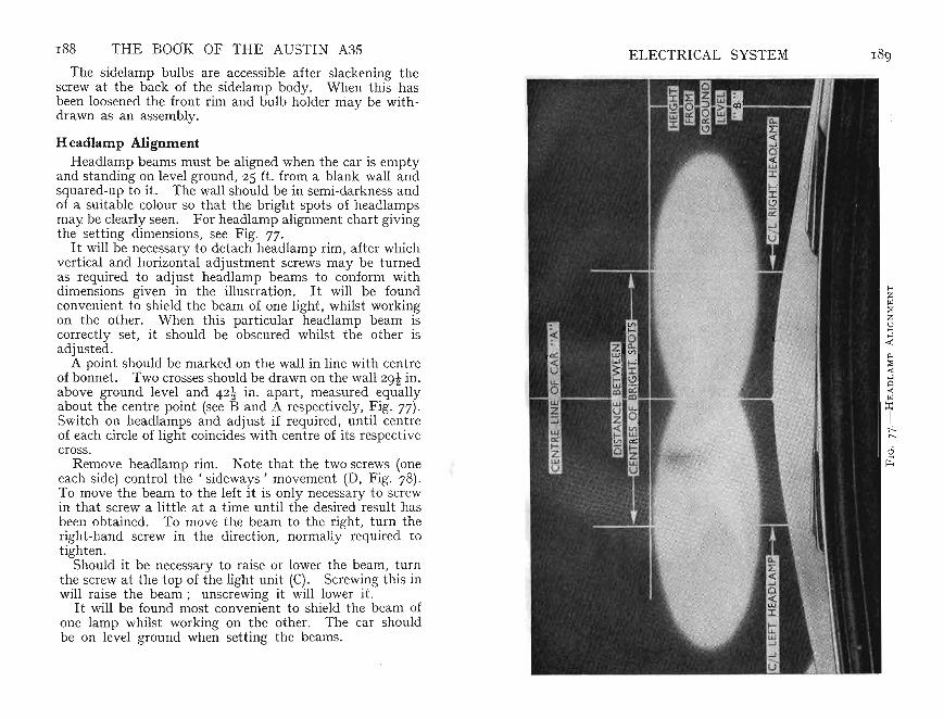
188 THE BOOK OF THE AUSTIN A35 E LECTRICAL SYSTEMThe sidelamp bulbs are accessible after slackening the
screw at the back of th e sidelamp body . When this hasbeen loosened the front rim and bulb holder niay be withdrawn as an assembly .
H eadlamp AlignmentHeadlamp beams must be aligned when the car is empty
and standing on level ground, 25 ft. from a blank wall andsquared-up to it . The wall should be in semi-darkness andof a suitable colour so that the bright spots of headlampsmay be clearly seen. For head lamp alignment chart givingthe setting dim ensions, see Fig . 77.
It will be necessary to detach headlamp rim, afte r whichvertical and horizontal adjustment screws may be turnedas required to adjust headl amp beams to conform withdimensions given in the illustration. It will be foundconvenient to shield the beam of one light , whilst workingon the other. When this particular headlamp beam iscorrectly set, it should be obscured whilst the other isadjusted .
A point shou ld be marked on the wall in line with centreof bonnet. Two crosses should be drawn on the wall 29t in .above ground level and 42t in . apart, measured equallyabout the centre point (see B and A respectively, Fig. 77).Switch on headlamps and adjust if required , until centreof each circle of light coincides with centre of it s respectivecross .
Remove headlamp rim . Not e that the two screws (oneeach side) control the' sideways ' movement (D, Fig . 78).To move the beam to the left it is only necessary to screwin that screw a little at a t ime until the desired result hasbeen obtained. To move the beam to the right, turn theright-hand screw in the direction, normally required tot ighten.
Should it be necessary to raise or lower the beam, turnthe screw at the top of the light unit (C) . Screwing this inwill raise the beam; unscrewing it will lower it.
It will be foun d most convenient to shield th e beam ofone lamp whilst working on the other. The car shouldbe on level grou nd when setting the beams.

F IG. 79.-REMOVAL OF G LASS OF . STOP L AMP
FIG. 7 8. - HEAD LAM P UNIT
A Light Unit . B Backshell, C Vertica l and D Horizonta l Adjustment. E Bulbholder. F Dust Excluder
F IG. 8 0. - NuMBE R- P LATE I LL U MI NATI ON
Flasher UnitThe flasher unit is contained in a small cylindrical metal
container, one end of which is rolled over on to an insulatedplate carrying the mechanism and three termi nals. Theunit depends for its operatio n on the linear expansion of alength of wire becoming heated by an electric curren t flowing through it. This actua ting wire controls the movementof a spring-loaded arma ture attached to a central st eel coreand carrying a moving contact.
This actua tes a warning lamp indi cating that flasher unitis fun ctioning correctly. It also gives warning of any bulbfailure occurr ing in the exte rnal dir ection-indicator lamps.The warning lamp is located on the facia and is incorpo ra ted in the indicator swit ch.
Replacing the Number-plate LampTo change the nu mber-plate lamp bulb all th at is neces
sary is to unscrew the securing screw in the middle of thecover (Fig. 80). In detaching this cover t ake care not todamage the sealing-washer fitt ed around it.
It is usually helpful to clean this lens inside and outsidewhen thus removed, permitting· maximum number-pla teilluminati on. The lamp bulb is of th e 6-watt type.
ELECT RICAL SYSTEM 191
ensure It IS fitted the correct way round. The stop / tai llamp bulb is of the double-cont act type, the cap providin gthe ear th return.
THE BOOK OF THE AUSTIN A35
Stop and Tail Bulb ReplacementShould it be necessary to replace the sto p- or tail-lamp
bulb, access is obtained by removing the lens. The ru bberring hasa double lip. By pulling back the outer lip, therim can be detached. The inn er lip, which secures thelens, will then be disclosed and can be drawn back t o freethe lens (Fig. 79). The bulb can then be detached.
It will he seen th at the bulb has offset secur ing pins to .
1 9 0

1 92 THE BOOK OF THE AUSTIN A35
Instrument-panel Lights
The instrument-pan el bulbs ar e held in a hold er. Thisis a ' push-fit' in a mounting behind the dash-boar d.When replacing these lamps do not pull the holder out ofits position by the cable or this may break. Grasp it withthe fingers and draw it out of its location .
Ignition-warning LampThe bulb is screwed into a holder to remove which all
that is necessary is to pull it gently from its mountingbehind the pan el. Do not attempt to dr aw it out by pullingt he terminal wire or t his may be damaged.
Fault Finding and TestingA useful accessory for the own er who is prepared to do
the small routine checking that is occasionally necessaryis a test lamp. This is simply a lamp holder with t wolength s of wire that may be as long as is conve nien t.
By , earthing ' one wire and touching the other on the, feed' of the suspected com ponent it can be ascertainedif cur rent is available at the point being checked . Itshould be noted , however , that the earthed wire must beplaced on bare metal and not on paint, which is an insulator.
The method of use is as follows:Suppose the horn will not work. Test by earth ing one
wire of the test lamp and connect the other to the hornterminal that has the brown and green wire connected toit. This is the 'feed '. The lamp should light showing there is current at that point. If it does not , checkthe fuse and the various connect ions for a br eak or loosecontact .
If it does light, earth the horn termina l having the singlebrown and black wire and the horn sho uld sound. If itnow works t he fault is in the switch or the lead to it fromthe horn . If it does not sound the fault lies in the horn.Possibly the contacts are dirty or requir e adjustment .
CHAPTE R X I II
LUBRICATION
T WO THINGS will probably impress th emselves onyour notice-the continual advice to use the correct
grade of a good qu ality lubricant an d the considerablediscrepan cy in pri ce as between expensive and cheap oilson th e market . A kn owledgeabl e friend ofte n shows hisadmiring audience how to test a sample of oil by dippinghis finger in it and rubbing it between finger and thumbto determine it s oiliness, body quality, etc. Such test sin the modern oil refinery require expensive instruments aswell as skilled t echni cians to ca rry out with certainty.
It is true to say that you never get 'something fornothing ' and for the sake of a sligh t saving in the initialcost of oil, considerable expe nse may be caused due to somebreakdown of the oil film under heavy-load conditions.Apart from the dam age that can occur to the engine itselfthere is also the poss ibility that there may be a breakdownon the open road necessit a tin g the ser vices of a breakdownwagon to tow the car to a service st ation.
The main difficulties that confro nt the oil refiners areth ese : (a) when the engine is cold the oil must not betoo thick to flow readily under pressure to the bearings,nor must it make the engine too sti ff to turn; (b) when theengine has warmed up the oil mu st not thin out to such adegree that it will allow the heavily st ressed working partsto come in metallic contact with one another nor, underthese conditio ns, mu st it form carbon particles or sludge ;and, finally, (c) it mu st ret ain its lubricating qualities fora considerab le length of time bearing in mind that it maybe diluted, particularly in winter, with petrol that reachesthe sump un der cold starti ng conditions. Cheap oils ar egenera lly unsatisfactory under at least one of these headings,and it should be remembered that as your Aust in A35engine will revolve at speeds in excess of 4,700 r.p .m. theoil film must not br eak down under the bearing loadsresulti ng.
193

194 THE BOOK OF THE AUSTIN A35 LUBRICATION 195Thus, it is a wise policy always to buy a good grade of
well-known branded oil and having made your choice touse always the same maker's product . Follow the instructions with regard to periods at which the oil should bechanged and conscientiously work to the rule. Lubricati onperiods have been determined after considerable researchand experience to ensure satisfactory performa nce and longlife of the working parts. It is up to you to do your shareby seeing tha t the va rious points ar e given regular attention.
Choice of Lubricants
The colour or appearance of an oil at at mospheric ternperatures gives no indication as to it s efficiency underopera ting conditions. Owners are advised to use onlyofficially recommended lub rican ts as list ed on page 2 17.
It is app reciated that in some remote areas these oils maynot be available, in which case only good qualit y oils conforming with S.A.E . numbers list ed should be used .
The letters S.A.E., followed by a number, constitute aclassification of lubricant in terms of viscosity or fluidity .For instance, a low S.A.E. nu mber, indi cating that it is oflow viscosity, means that it flows more readily than oil witha high viscosity rating. It will be appreciated, therefore,tha t oil with a low S.A.E. number is essential if easystarting is to be obtained in cold weather. On the otherhand, in hot weather a higher viscosity oil is desirable inorder to keep oil consumption within normal limits.
Even the best oils become contaminated in t ime wit hunburnt fuel, carbon, metallic particles, and moisture. It ismost importan t , therefore, that oil is changed at recommended mileages.
Upper Cylinder LubricationUse of upper cylinder lubricant is desirab le a t all t imes,
but most particularly during the running-in period of areconditioned engine. See page 2 1 7 for recommendedbrands.
Multigrade Motor OilsIn addit ion to recommended lub ricants, multigrade oils,
as produced by oil companies shown on the list, may beused for all climatic temperatures unless your engine is old
and in poor mechanical condition. Some brands are moreexpensive than recomm ended motor oils because of theirspecial properties and grea ter fluidity at low temperatures.
Engine Lubrication SystemOil for the engine is carried in the sump bolt ed to crank
case. A pump, driven by skew gears from camshaft ,delivers oil un der pressure to va rious bearing surfaces.Delivery is by way of an oil gallery ru nning along righthand side of engine t o three main bearings and thence,through drilled passages in crankshaft, to big-end bearin gs.Passages in engine block also conduct oil to the threecamshaft bearings.
As already exp lained , a warning light is connected to oilgallery so that the dri ver can readily see whether oil pumpis fun ctioning correctly. If thi s light flashes, particularlywhen rounding corners, check oil level. Never allow engineto run unless absence of warning light shows the system tobe working satisfactorily .
The cylinder walls and gudgeon pins are normally lubricated by oil flung off th e big-end bearings, but to ensurethorough lubrication there is a small jet hole in the top halfof each connect ing-rod big-end bearing (10, Fig. 39).
The camshaft timing chain is lubri cated by oil fed to it~rom th e gallery via th e front camsha ft bearing. This bearmg has a passage communicating with the forward end onwhich th e camshaft timing wheel is mounted. A numberof slots cut in the camshaft thrust washer allow oil to reachth e wheel. Centrifugal force then carr ies th e oil outward sto the chain keeping the links and rollers in a well-lubricatedcondition.
L~bric~tion for the overhead-valve gear is provided byleadmg 011at a reduced pressure from one camshaft bearin gthrough a drilled passage to the valve-rocker shaf t. Eachrocker is drilled so th at not only is each bearin g lubricatedat the point where it moves on the rocker shaft but thespherical end, which is carried in the push rod, floats on afilm of oil delivered under pressure. Not only is weararrested but quiet operation is assured by this means.Surplus oil returns to the sump.
Immediately above the gudgeon pin each piston carries anoil-control or scraper ring, slotted around it s circumference.

and the loss becomes greater as the element becomescontaminated by foreign matter removed from fuel oil.
A bal anc e-valve is provided to guard against the possibility of filter becoming complet ely choked and therebypreventing oil from reaching t h.e bear~ngs. This ~:>alance
valve is set to open when t here lS an 011 pressure differenceof IS to 20 lb. per sq. in. as between inside and outside offilter element. It is non-adjust abl e. .When the valve isopen , un-filtered oil by-passes element and reaches beari~gsat a redu ced pressure of ap prox imate ly 35 lb. per sq . m .Therefore , to ensur e that only filte red oil is supplied it isessential that element should be renewed at 6,0 0 0 miles, orwhen oil pressure gauge indicates that a change is necessaryby a fall in pressure.
196 THE BOOK OF THE AU STIN A35
The oil it collect s is free to pass through corres ponding holes in the pisto n ring groove a~d so back to th~ sump.
Points at which there could be 011 leakage are situate dat each end of crankshaft. " At front end adjacent to pulleyis a felt oil ret ainer fitted into a groove and embracing thecircumference of the cranksha ft . Immediately behind thisis a thrower , the purpose of which is to fling off by centrifugal force any oil that t ends to work it s way along t hecrankshaft. At rear end of crankshaft there is anotherthrower to prevent oil from escaping past rear main bearing.Apart from needless waste, it is impor.tan.t to keep ?il fromthe working faces of the clutch otherwise it would slip whenunder load .
LUl:$KICA"l"lUN 197
Full-Flow Oil FilterBefore reaching the engine bearings the oil is passed
through an oil filt er of the full-flow type (Fig. 8I). Its
Il
F IG. 8r.-FuLL-FLow TYPE FILTER
element consists of a st ar formation of special quality feltselected for its filtering properties. Oil is passed to thefilter from the pump at a controlled pressure of 60 lb. persq. in. Obviously, some pressure will be lost in this process
Regularity of Engine LubricationIt is imp ortant that the sump of a reconditioned engine
should be drained and refilled with new oil afte r the first500 miles. Inevitably, minute particles of foreig~ m.atter,fluff, etc. , will circulat e with the oil as the new engme is runin . Once these particles have been drain ed off and thebearings have become highly.polished, t he .c~ean new oil wi~l
keep the working surfaces m good condit ion, After thisinit ial draining period the oil should be changed after thenext 3,000 miles . Thereafter, change it every 3,000 ~iles
and replace the filter unit at approxim ately 6,000 miles,as mentioned above. The drain plug is located at rearright-hand extremity of sump (5, Fig. 59). Care should betaken to ensure that no dirt or grit enters sum p when replac-ing the plug. Capacity : 6 pints. .. .
Check oil level daily by means of dip-st ick (Fig. 6).This will give you an accurate indicati?n of it s condi~io.n
as well as it s quantity. If there are slgns that the 011 lSbecoming dirty-for instance, if water is present-thesump should be drained and refilled with clean oil. A neweleme nt should be fitted at the same time (see next page).Should you have t o replenish the sump the few shilli~gs
spent on clean oil is far more economical than attemptmgto make do with dirty oil, bearing in mind the cost of anyrepairs that might easily be caused by a breakdown in thelubricating system.

198 THE BOOK OF THE AUSTIN A35 LUBRICATION 199
Renewing Filter ElementFirst drain filter by removing centre fixing bolt from bas e
of container (Fig. 81). With bolt removed it will benecessary to sup port container by hand, until all oil hasdrained away. Withdraw container complete with element, slide out element, and-using a non-fluffy cloththoroughly clean container internally of all foreign matterthat has been trapped. Insert a new element and, holdingcentre fixing bolt in position against bottom of container,fill with new oil. Now, still holding bolt in position, locateit in filter head casting and tighten sufficiently to make anoil-tight joint. Then top-up sump with oil. Make surethat no fibres from the cleansing operation remain in thecontainer before inserting the new element .
This is the only attention likely to be required but it isimportant to note that filter container should not be removed other than for fitting a new element. To disturbit invites the hazard of added contamination from accumulated dirt on outside of filter entering container and of thisbeing carried to bearings on re-starting engine.
Start the engine and allow it to tick over steadily) at thesame time carefully examining the connection for any signsof oil leakage. Even a slight leakage of oil can accountfor considerable loss, bearing in mind that this leakage willoccur during the whole time the engine is running. It iswell worth while to make sure that the work has been donesatisfactorily before taking the car on the road again.
Make certain that all mounting bolts are tight.
Sump Removal and Oil-pump MaintenanceThe full-flow filter will keep oil clean for a considerable
time, and it is not normally necessary for sump to bedropped and oil-pump filter cleaned.
Should there be any marked decrease in oil pressure,shown by oil-pressure light glowing, it may be that oil hasbeen diluted somewhat. Refilling with correct grade of oilmay restore pressure. On the other hand, there is thepossibility that pressure-release valve is held partly opendue to intrusion of particles of foreign matter. Instructionsfor cleaning this pressure-release valve are given on page 20L
Supposing that these points have been checked and that
the pressure remains below normal, oil-pump filter mayhave become choked. To remedy this it will be necessaryto remove sump. Th ere is nothing particularly difficultin this operation but take care to refit it correctly, otherwise oil leakage may occur and besides being messy oilloss in such circumstances can be expensive.
If you decide to do the work yourself it will be helpfulfirst to raise the car at the front on suitable solid packingto give more room in which to work. Take care to chockrear wheels and also to apply handbrake to prevent carmoving off supports whilst you are underneath it.
Unscrew drain plug at rear of sump and allow oil toescape, not forgetting that there will be approximat ely6 pints in the sump (5 Fig. 59). Place a temporary support under sump it self and then undo securing bolts. Thesump is secured in position by thirteen set-screws withwashers. A nut and bolt-with flat and spring washeron left-hand side beneath fuel pump holds petrol drain pipeby means of a suitable bracket.
When all screws have been removed hold sump with onehand, remove temporary support and then carefully lowersump. If at first it will not drop downwards out ofposition, ease it away carefully at each side but take carenot to damage sump face.
Having lowered the sump, the oil st rainer or filter will bedisclosed. It can be washed without further dismantling.It will be found more convenient to unscrew and removethe bolt that passes through the cent re of the oil-strainerbody (7, Fig. 82) after which the bottom cover can be takenaway and cleaned. The gau ze on the oil-strainer body canthen more easily be cleaned for you can now get at bothsides of it . Do not use a rag, use a brush.
There are two things to watch when replacing the bottomcover. A distance piece (2, Fig. 82 is fitted between bottomcover and top of oil-strainer body, the bolt passing throughthe centre of it. The purpose of this distance piece is toprevent the oil-strainer body from being unduly compressedand distorted when the bolt is tightened up. The otherimportant point is that the bottom cover must be so fittedthat the solid segment is towards the pump body. It willbe noticed that there is a small tongue formed on the coverand that it engages with a corresponding slot machined to
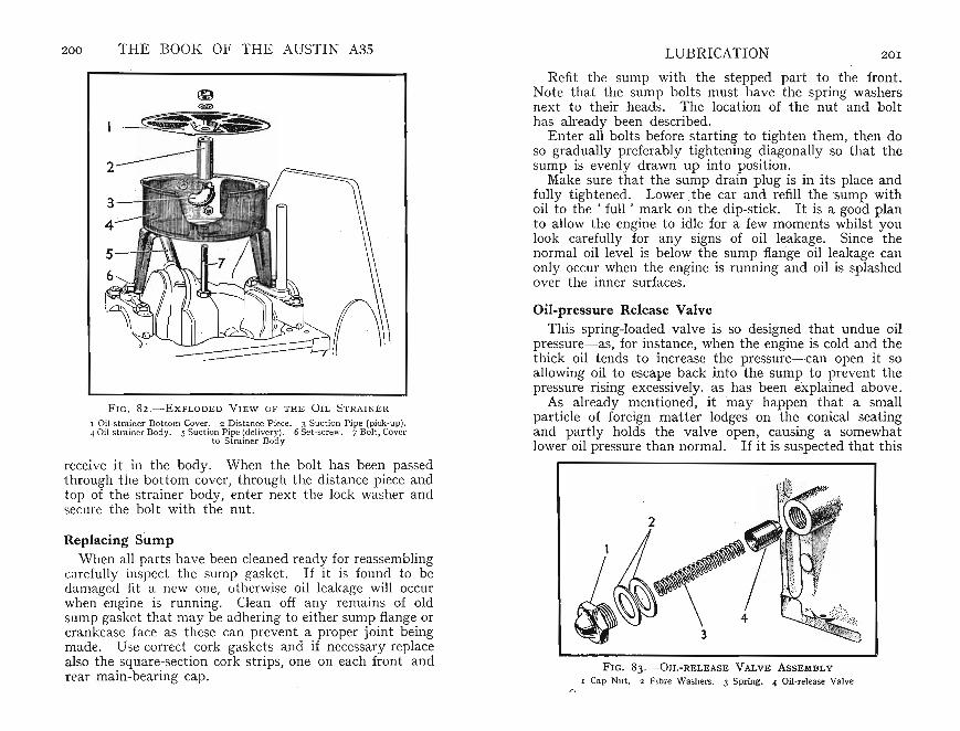
200 THE BOOK OF THE AUSTIN A3S LUBRICATION 20 1
FIG. 82 ,-ExPLODE D VIEW OF TH E OIL S TRAINER
I Oil-strainer Bottom Cover , 2 Distance Piece. 3 Suction Pi pe (pick-up).4 Oil-strainer Bod y, 5 Suct ion Pipe (delivery). 6 Set -screw. 7 Bolt, Cover
to Strainer Bod y
receive it in the body. When the bolt has been passedthrough the bottom cover, throu gh the distance piece andtop of the st rainer body, enter next the lock washer andsecure the bolt with the nut.
Replacing SumpWh n all pa rts have been cleaned ready for reassembling
',H fully inspect the sump gasket. If it is found to bedamag d fi t a new one, otherwise oil leakage will occurwhen ngine is ru nnin g. Clean off any remains of oldsump gasket that may be adhering to either sump flange orcrank case face as these can prevent a proper joint beingmade. Use correct cork gaskets and if necessary replacealso the square-section cork strips, one on each front andrear main-bearing cap .
Refit the sump with the stepped part to the front.Note that th e sump bolts must have the spring washersnext to their heads. The location of the nut and bolthas already been describ ed.
Enter all bolts before starting to tighten them, then doso gradually preferably tightening diagonally so that thesump is evenly drawn up into position.
Make sure that the sump drain plug is in its plac e andfully t ightened. Lower .the car and refill the sump withoil to th e ' full' mark on the dip-stick. It is a good planto allow the engine to idle for a few moments whilst youlook carefully for any signs of oil leakage. Since thenormal oil level is below the sump flange oil leakage canonly occur when the engine is running and oil is splashedover the inner surfaces.
Oil-pressure Release ValveThis spring-loaded valve is so designed that undue oil
pressure- as, for instance, when the engine is cold and thethick oil tends to increase the pressure-can open it soallowing oil to escape back into the sump to prevent thepressure rising excessively. as has been explained above.
As already mentioned, it may happen that a smallparticle of foreign matter lodges on the conical seatingand partly holds the valve open, causing a somewhatlower oil pressure than normal. If it is suspected that this
FIG. 83 .- 0 I L- RELEA SE VALVE ASSEMBLY
I Cap Nu t. 2 F ibre Washers. 3 Spr ing. 4 Oil-release Valve

202 THE BOOK OF THE AUSTIN A3S LUBRICATION 2 0 3
has occurred all that is necessar y is to clean it. Unscrewthe hexagonal-headed plug in the side of the cylinderblock situated t owards the rear of the right-hand side ofthe crankc ase, so releasing the spring. By inserting asuit able probe the relief valve can be withdr awn from it shousing. Carefully clean the parts and examine the seat ingof va lve and cylinder block.
When reassembling (Fig. 83) ente r the valve conicalface end first followed by the spring. Two fibre washersmust be fitted over the threads of the va lve p lug ot herwisean oil leak may occur.
Valve-rocker Shaft
Due to the oil filtr ation arrangements it is unlikely thatthere will be any deposit s to obstruct the oilways. It isworth noting that the rocker shaft , which is drilled andfed with the oil under pressure for lubricating each rocker
A
F IG . 8 4.- S H OWING S CR E W ED PLU G (A) TH AT F ACILIT AT E SI NTE R N AL C LE A N I N G OF SHAFT
bear ing, can be cleaned if desired. Each end of the shaftis plugged , one end havin g a threaded plug secur ed by acotter pin (A, F ig. 84). To clean t he shaft th e cotter canbe withdrawn and the plug unscrewed giving access to theshaft itself.
Gearbox Lubrication .The working parts of the gearbox are lubricated by
, splash '. Provided that the corr ect level of a good grade
of gear oil is maintain ed, it will give long serv ice since theoil is circulated automatically to the various parts needing lubrication. If the oil level is allowed to fall unduly,wear and consequent ial damage can result. On the otherhand, if the gearbox is overfilled, ap art from possible lossat the rear , oil may work through to the clutch giving riseto clutch slip or uneven engagement .
It is normally only necessar y to check the oil level every1 ,0 0 0 miles or at monthly intervals.
FIG. 8 S .- ENGINE A N D G E AR B OX ( TE AR - SIDE )
I Gearbox Filler Plu g. 2 Drain Plug. 3 Cylind er Block Drain Tap
Remove the rubber plug on the left side of the gearboxcover to disclose beneath it the filler plug (I , Fig. 85).Wipe away any mud or dirt around the plug and then unscrew it . Always take great care to prevent particles ofgrit from reaching the working parts.
Check the level when the gearbox is warm after a run.Not only does the oil run out qui cker when warm but it willcarry with it the fine particles of foreign matter suspended
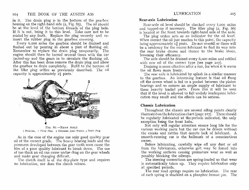
204 THE BOOK OF THE AUSTIN A35 LUB RICATION 2 0 5
in it . The drain plug is in the bottom of the gearboxhousing on the right-hand side (2, Fig. 85). The oil shouldbe at the level of the bottom threads of the plug hole.1£ it is not, bring it to this level. Take care not to bemisled by any froth. Replace the plug securely and reinsert the rubber plug in the gearbox covering.
Every 6,000 miles the gearbox should be drained andflushed out by pouring in about a pint of flushing oil.Remember to replace the dr ain plug temporarily. Theengine should then be turned severa l times with the carjacked-up and the gears in to circulate the flushing oil.After this has been done remove the drainplug and allowthe gearbox to drain completely. Refill to the bottom ofthe filler plug orifice as previously described. The oilcapacity is approximately 2t pints.
4F IG. 86.-REAR AXLE
1 Breather. 2 Filter Pl ug. 3 Universa l J oint Nipple. 4 Drain Plug
As in the case of the engine use only good quality gearoil of the corr ect grade. The heavy bearin g loads and thepressures developed between the gear teeth soon cause thefilm of a poor qualit y lubricant t o break down . The useof too thick an oil can cause un due drag on th e gear wheelsand make gear changing difficult.
The clutch itself is of the dry-plate type and requiresno lubrication, nor does the clutch release.
Rear-axle Lubri cationRear-axle oil level should be checked every 1,000 miles
and topped-up if necessary. The filler plug (2, Fig. 86)is located at the front towards right-hand side of the ax le.
The plug orifice acts as an indic ator for the oil level.When correct the oil just reaches to this point , the capacitybeing approximately I i pints. Do not overfill or there willbe a tendency for the excess lubrican t t o find its way intothe rea r brake drums and thence t o the brake shoes,lessening their efficiency.
The axle should be drained every 6,0 00 miles and refilledwith new oil of the correct type (see page 217).
Dr aining is mor e effective after a run, for when it is warmthe oil flows more freely.
The rear axle is lubricated by splash in a similar mannerto the gearbox. An int eresting feature is that oil flungoff the crown wheel is fed to a pocket between the pinionbearings and so assures an ample supply of lubricant tothese heavily loaded parts. From this it will be seenthat if th e level is allowed to fall unduly inadequate lubri cation may result and the effects can be serious .
Chassis LubricationThroughout the chassis are several oiling points clearly
illustrated on thelubrication chart (page 217). Theseshouldbe regularly lubricated at the periods indi cated, the onlyexception being the front hubs.
Not only will regular attention ensure long life for thevarious working parts but the car can be driven withoutthe creaks and rattles that denote lack of lubricant. Asmooth-running car is the hallmark of a conscientiousowner.
Before lubricating, carefully wipe off any dust or oilfrom th e lubricators, otherwise grit may be forced intothe working surfaces causing premature wear as well aspossibly blocking the oilways.
The steering conn ections are spring-loaded so that wearis automatically taken up. They require lubrication onlyat specified periods.
The rear roa d springs require no lubrication. The rearof each spring is shac kled on a ph osphor-bronze pin . The
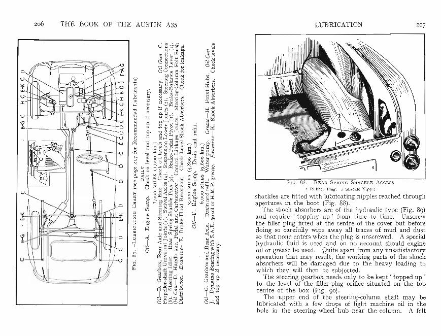
206 THE BOOK OF THE AUSTIN A35 LUBRICATION 2 07
,\
F IG. 88.-REAR SPRING S HACKL E A CCE SS
I Rubber P lug. 2 Sha ckle Nipple
shac kles are fitted wit h lubricating nipples reached throughapertures in the boot (Fig . 88).
The shock absorbers are of the hydraulic t ype (Fig. 8g)and require ' topping up ' from time to time. Unscrewthe filler plug fitted at the centre of the cover but beforedoing so carefully wipe away all traces of mud and dustso that none enters when th e plug is unscrewed. A specialhydraulic fluid is used and on no account should engineoil or grease be used. Quite apart from any unsatisfactoryoperation that may result, the work ing parts of the shockabsorbers will be damaged due to the heavy loading towhich they will then be subject ed.
The steering gearbox needs only to be kept' topped up ,to the level of the filler-plug orifice situated on the topcentre of the box (Fig. go).
The upper end of the steering-column shaft may belubricated with a few drops of light machine oil in thehole in th e steering-wheel hub near the column. A felt

208 THE BOOK OF THE AUSTIN A3S LUBRICATION 209
washer is fitted inside the column itself to retain thelubricant.
FIG. 8g.-SHOCK A BS OR BER AND STABILIZING BAR
I Stabilizing Bar . 2 Shock Absorber . 3 Shock Absorber/Axle Link
Summary
The following list gives the points requmng attentionat the various periods. Work through this list regularlyand systematically so that no detail is overlooked.
Daily: Check engine oil level and fuel tank contents.See that there is sufficient water in the radiator.
Weekly: · Tyres: Check pressures-not forgetting thespare wheel, otherwise you may find this is flat when youwant it urgently. It is advisable also to remove any flints ,nails etc., that may have become embedded in the treads.For tyre pressures see page 38.
Every 1,000 MilesRear Spring Shackles: One each side. Lubricate with
oil gun. Do not attempt to add penetrating oil or lubricat-
FIG. gO.-STEERING Box ATTENTION POINTS
I Adju stin g Screw. 2 Fill er Plug
ing oil to any of the spring eyes of shackles except thosementioned in this section.
Front Suspens ion: Lubricate with oil gun the lowerarm joints where they join the swivel axle (Fig. 21). Thereis a lubricator on each side.
Swivel Axles : If the car is jacked up when lubricating
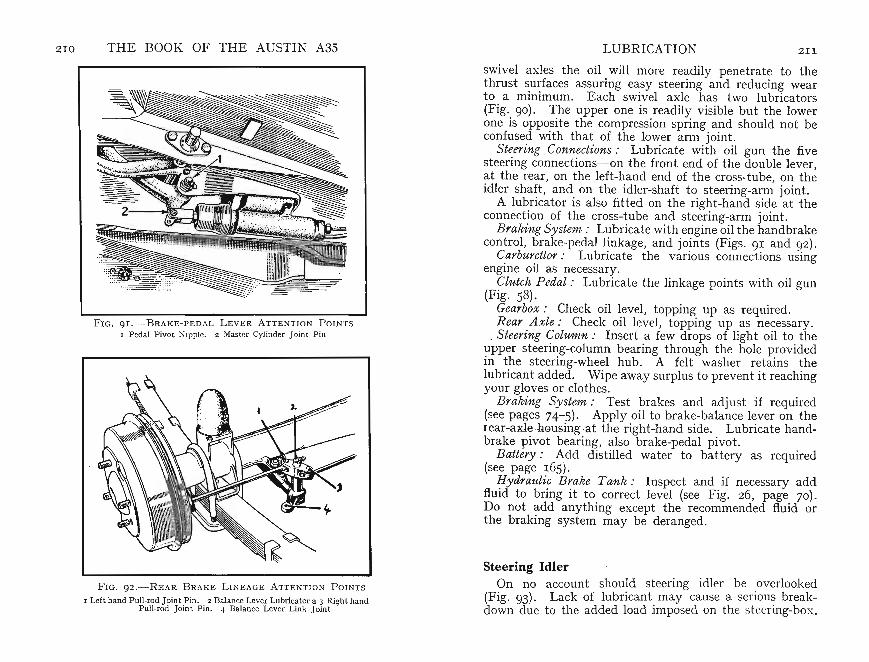
Z10 THE BOOK OF THE AUSTIN A3S LUBRICATION ZII
F IG. 9I.-BRAKE -PEDAL L EVE R ATTE N TI O N P OI N T S
I Pedal Pivot Nipp le. 2 Master Cylinder J oint P in
FIG. 92.- REAR BRAKE L I N E AGE ATTE NTION P OI N T S
I Left hand Pull-rod J oin t Pin . 2 Balance Lever Lubrica tor a 3 Right handPull- rod J oint Pin. 4 Balance Lever Lin k Joint
swivel axles the oil will more readily penetrate to thethrust surfaces assuring easy st eering and reducing weart o a minimum. Each swivel axle has two lubricators(Fig. 90). The upper one is readily visible but the lowerone is opposit e the compression spring and should not beconfused with th at of the lower arm joint.
Steering Connections: Lubricate with oil gun the fivesteering connections-on the front end of the double lever,at the rear, on the left-hand end of the cross-tube, on theidler shaft , and on the idler-shaft to steering-arm joint.
A lubricator is also fitted on the right-hand side at theconnection of the cross-tube and steering-arm joint.
Bra/ling Sy stem : Lubricat e with engine oil the handbrakecontrol, brake-pedal linkage, and joints (Figs. 91 and 9z).
Carburettor : Lubricate the va rious conn ections usingengine oil as necessary .
Clutch Pedal : Lubricate the link age points with oil gun(Fig. 58).
Gearbox: Check oil level, topping up as required.Rear Axle: Check oil level, topping up as necessary.
. Steering Column: Insert a few drops of light oil to theupper steering-column bearin g through the hole providedin the steering-wheel hub. A felt washer retains thelubricant added . Wip e away surplus to prevent it reachingyour gloves or clothes.
Braking System: Test brakes and adjust if required(see pages 74-5) . Apply oil to brake-balance lever on therear-a xlehousingat the right-hand side. Lubricate handbrake pivot bearing, also brake-pedal pivot.
Battery: Add distilled water to battery as required(see page 165).
Hydraulic Brake T ank : Inspect and if necessary addfluid to bring it to correct level (see Fig. z6, page 70).Do not add anything except the recommended fluid orthe braking system may be deranged.
Steering IdlerOn no account should steering idler be overlooked
(Fig. 93). Lack of lubricant may cause a serious breakdown due to the added load imposed on the steer ing-box .

212 THE BOOK OF THE AUSTIN A3S LUBRICATION ' 2 13
F IG . 93 .-- S TE E RING I DLE R . A : F ILLE R P LUG
Steering Connections
Apply oil gun . to s~eering cross-t ube nipples (2, Fig. 94)and ~o t~e st eenng side tube nipples (3 and 4) and top ofst eenng Idler by filler plug (A, Fig. 93).
Propeller-shaft Univ ersal Joints: Lubricate at each endo~ universal joint. .It may be necessary to move carslightly so that lubncator can be reached (5, Fig. 60a) .
Front Hu.bs. After 6,000 miles unscrew hub cap andre-charge WIth grease. It is important that hub s are notover-greased. Some models have a knock-in cap and thismust be levere~ off to enable grease to be applied.
Rear Hubs. . These do not require any attention for theyare packed WIth grease on assembly at the works.
Every 3,000 Miles or Monthly. Engine : Drain off old oil in sump and refill with new
0 11 of the correct grade.Fan-belt : Check tension and adjust if necessary as
described on page 130.Oil Sump and Pump Strainer: Remove and clean as
desc~ibe~ on page 198.Oil Filter : Replace unit as described on page 196.
F IG . 9 4.- S TEERI NG C ONN E CTI ONS : A TTEN TI ON POINTS
I Shock Abs orb er F iller P lug. 2 Cross-tube . 3 and 4 Side-tube Nip!?les
Every 6,000 MilesAir Cleaner: Remove air cleaner by loosening clamp
ing bolt and connection to valve chamber cover. Whenremoved rinse louvred end in petrol and when dry add cleanengine oil to gauze mesh. Allow any surplus oil to drain offbefore replacing (see page 114). Make sure connection tovalve chamber cover is correctly made.
Sparking Plugs : Remove and clean (for further instructions see page 178).
Distributor: Remove distributor cap and detach rotor towhich add a few drops of thin oil at the screw (Fig. 68).A duct will allow this oil to lubricate the bearings. Applya smear of engine oil to distributor cam. Test contactpoints for free movement and lubricate contact pivot , butdo not allow any lubricant to reach points. Add a few
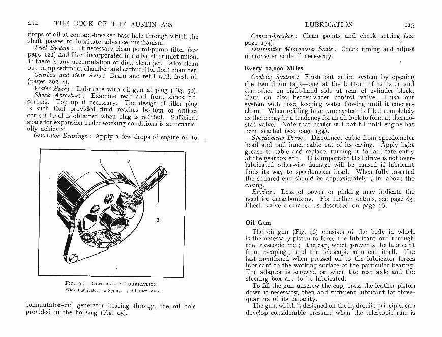
214 THE BOOK OF THE AUSTIN A3S
drops of oil at contact-breaker base hole through which thesha ft passes to lubricate advance mechanism.
Fu el System : If !1ecessary cle~n petrol-pump filter (seepage 1 21) and filter mcorporated m carburettor inlet union.If there is any accumulation of dirt, clean jet. Also cleanout pump sediment chamb er and carburettor float chamber.
Gearbox and Rear A xle : Drain and refill with fresh oil(pages 202-4).
Wat er Pump: Lubricate with oil gun at plug (Fig. 50).Shock Absorbers: Examine rear and front shock ab
~orbers . Top up i~ necessary. The design of filler pluglS such that provided fluid reaches bottom of orificescorrect level is obtained when plug is refitted. Sufficientspace for expansion under working conditi ons is automatically achieved.
Generator B earings: Apply a few drops of engine oil to
2
F I G . 9 5.- GENER ATOR LU B R IC ATION
Wick Lu bricat or. 2 Spring. 3 Adjus ter Screw
commutator-end generator bearing through the oil holeprovided in the housing (Fig. 95).
LUBRICATION 2 15
Contact-breaker: Clean points and check set t ing (seepage 174)·
Distributor Micrometer Scale : Check timing and adjustmicrometer scale if necessary.
Every 12,0 0 0 MilesCooling System : Flush out entire system by OPening
the two drain taps-one at the bottom of radiator andthe other on right-hand side at rear of cylinder block.Turn on also heater-water control va lve. Flush outsyst em with hose, keeping water flowing until it emergesclean. When refilling take care system is filled completelyas th ere may be a tendency for an air lock to form at thermostat valve. Note that heater will not fill until engine hasbeen started (see page 134).
Sp eedometer Drive : Disconnect cable from speedometerhead and pull inn er cable out of its casing. Apply lightgrease to cable and replace, turning it to facilitate entryat the gearbox end. It is important that dri ve is not overlubricated otherwise damage will be caus ed if lubricantfinds its way to speedometer head. Wh en fully insertedth e squared end should be approximately i in . above thecasing.
Engine: Loss of power or pinking may indi cate theneed for decarbonizing. For further details, see page 83.Check valve clearance as described on page 96. '
Oil GunThe oil gun (Fig. 96) consists of the bod y in which
is the necessary piston to force the lubricant out throughthe telescopic end; the cap, which prevents th e lubricantfrom escaping ; and th e telescopic ram end it self. Thelast mentioned when pressed on to the lubricator forceslubricant to the work ing surface of the particular bearing.The adaptor is screwed on when the rear axle and thesteering box are to be lubricated.
To fill the gun unscrew the cap , press the leather pistondown if necessary, then add sufficient lubricant for threequarters of its capacity.
The gun, which is designed on the hydraulic principle, candevelop considerable pressure when the telescopic ram is

>;j
~.
p.>....
>;j
NPo>
::s>
;jro
...."""
(7Q
1orl
.....Po>cj~~
0'>
CD0
::r'::4
.r.n~
.en
N'"1CD
l-+,
CD~(l)
~H
......
...0
.'1'<~
0C
C)'
O0
d?6::sS~ri::S
~~
>-J(f)
::;:
g:.
::S~
8'oS
::t:o
(f)r
o0
.....
t>l~
Qt=:
l~
(t)
.....
....
...
::r'
0'"
..i-®
,,-:::
;:o..
l--'
aC'D
"'~
to~.S~O~
'"('
)'
0'"
1:::
r'rl-
.....
~td~
/~0
n'~
ropo
"Sf
'tl
Pi':::
Po>ro
::Sro
~.
t>ll;
;'a
.....;:
l'>
0"£
~\0
6:8p
/"
0::
r't-
--I
(1
)rl-
(Erl-
(t)::;
:e;
o.g
~I
Iorl
o'<
::S~
.:-
,
0"
o(7Q
::s0
'"....
,>-J
rop.>
.....(7
Q....
..:"
'>
-j~
(!.
t'!::t:
~r;;
g"~
::S'1j~
•u>
...<'tl
rl-
b>~
9t=:
lro
(7Q0
po"
8s
r-0
.8
~....
~.
>-
o.(f
)'8
",0
~~?
::r~
0"
c:;cj
ro(')
(f)p.>
p.>!P
z(J
l
Z"po"~
....
.'<
..>-J
o::s
'<....
.0
(')
......
0-
:>;,
C"l
po
"po
";0
Z::l
.ro
rop.
>C1>
0;;
'C"
l....
.o.
::s
.....
...'"
>p.>
.....,
.....p
o":
:;.0
.~
<OC"
l~
o'ro
.....>
;j0
"~
CJl
::s>
;j0
....::l
.o
~....
~£
po"
~(7
Q~::
sPo>
(7Q...
......
....
....CD
::t."r
o_.
,.....
(f),
(f)
RE
CO
MM
EN
DE
DL
UB
RIC
AN
TS
B.P
.D
UC
KH
AM
'SV
AC
UU
MS
HE
LL
WA
KE
FIE
LD
ESS
O
Abo
ve32
0F
.E
ner
gol
Duc
kham
'sE
sso
Ext
ra(0
·C
.)SA
E30
'NO
LT
bin
y'
Mo
bilo
ilA
X-I
OO
30C
astr
clX
LM
oto
roil
20W
/30
En
gin
e3Z
·F
.(0
·C
.)E
nerg
cl
Duc
kham
'sM
ob
iJo
ilX
-IO
OC
astr
olit
eE
sso
Ext
rado
wn
to10
·F
.SA
EZ
OW
'NO
LT
wen
ty'
Arc
tic
ZO/Z
OWM
otor
oil
20W
/30
(-
J2·C
.)
Bel
ow10
·F
.E
ner
go
lD
uckh
am's
Mo
bilo
ilX
·lO
OC
astr
olZ
Ess
olub
c10
(-IZ
·C.)
SAE
lOW
'NO
LT
en'
lOW
lOW
Tra
nsm
issi
on..
..E
ner
gol
Duc
kham
'sM
obil
oiJ
AX
-IOO
30C
ast
ro!
XL
Eas
olu
be
30SA
E30
'NO
LT
bir
ty'
Rea
rA
xle,
Ste
erin
gB
ox,
and
Wat
erE
nerg
olE
PD
uck
bam
'sM
obil
ube
Spi
rax
90C
astr
o!
Ess
oB
xpee
Pum
p..
..S
AE
90H
ypo
id90
GX
90
EP
Hyp
oyC
om
po
un
d90
,O
ilN
ippl
es..
Ene
rgo
lE
PD
uck
ham
'sM
obilu
beS
pira
xC
ast
roE
sso
Exp
eeS
AE
140
NO
L.
EP
.140
GX
140
1'40
EP
Hi-
pre
ssC
om
pou
nd14
0I
Fro
ntW
beel
Hu
bs..
Ene
rgre
ase
L3
Duc
kham
'sM
ob
ilG
reas
eR
eun
axA
Cae
trol
ease
Ess
oM
ult
i-pu
rpo
seL
.B.1
0G
rea
seM
.P.
L.M
.G
reas
eH
Dis
trib
utor
and
Oil
Ca
n.E
nerg
olD
uck
ham
'sM
obi
lx
.ioo
Wak
efie
ldE
sso
Han
dy
'SA
E20
W'N
OL
Tw
enty
Han
dy
Oil
20/l
0W
Eve
rym
anO
ilO
il
:-...
..D
uckh
am's
Upp
erC
ylin
der
Lub
rica
tion
Bn
erg
ol
UC
LA
dco
idM
obi
lD
onax
UW
akef
ield
Ess
eU
ype
rL
iqu
idU
pper
Lub
eC
astr
ollo
Cyl
.L
ub
rica
nl
~ I ~ en ~ 0-3
[1] ~ g ~ ~ o :j ~
Rea
rA
xle
and
Stee
ring
:O
ilN
ippl
es:
Hyd
rau
lic
Bra
kes
:S
hock
Ab
sorb
ers:
For
tem
pera
ture
sbe
low
10°
F.
(_1
2°C
.)u
seS
AE
80H
ypoi
dL
ub
rica
nt.
Fo
rhi
gbte
mpe
ratu
recl
imat
esth
eg
reas
eas
sho
wn
(or
bu
baca
nb
eu
sed
.U
seG
en
uin
eL
ockh
eed
Bra
keF
luid
only
.U
seA
rmst
ron
g's
Sup
er
Th
inSh
ock
Abs
orb
erO
il.
FIG
.9
7.-R
EC
OM
ME
ND
ED
LU
BR
ICA
NT
S


![Christopher Cassell [1,2] (BSc, Hon) ESR 15](https://img.dokumen.tips/doc/110x75/568165f8550346895dd92377/christopher-cassell-12-bsc-hon-esr-15.jpg)