Embed Size (px)
Citation preview

1 | P a g e
CASE TOOLS AND WEB TECHNOLOGIES LAB
LAB MANUAL
Subject Code: A60591
Regulations: R13 – JNTUH
Class: III Year II Semester (CSE)
Prepared By
Mr. N Rajasekhar
Assistant Professor
Ms. Y Deepthi
Assistant Professor
Ms.S Swarajya Laxmi
Associate Professor
Department of Computer Science & Engineering
INSTITUTE OF AERONAUTICAL ENGINEERING (Autonomous)
Dundigal – 500 043, Hyderabad.
2 | P a g e
INSTITUTE OF AERONAUTICAL ENGINEERING (Autonomous)
Dundigal - 500 043, Hyderabad.
COMPUTER SCIENCE AND ENGINEERING
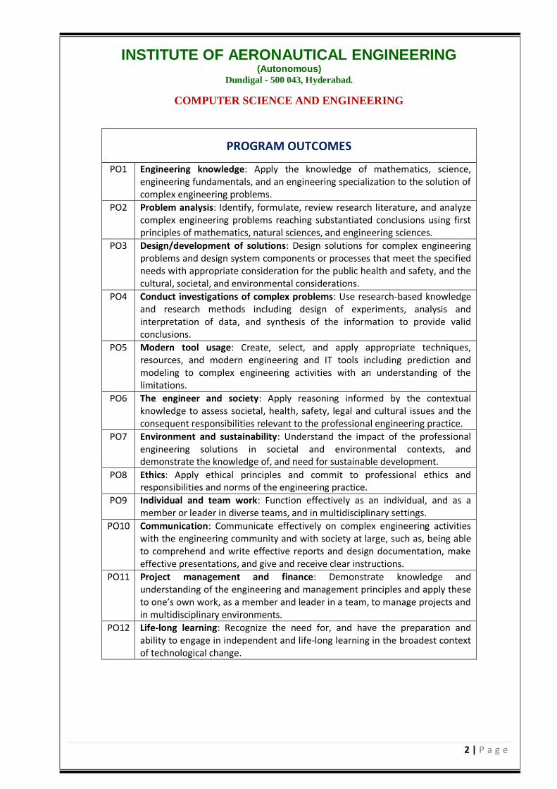
PROGRAM OUTCOMES
PO1 Engineering knowledge: Apply the knowledge of mathematics, science, engineering fundamentals, and an engineering specialization to the solution of complex engineering problems.
PO2 Problem analysis: Identify, formulate, review research literature, and analyze complex engineering problems reaching substantiated conclusions using first principles of mathematics, natural sciences, and engineering sciences.
PO3 Design/development of solutions: Design solutions for complex engineering problems and design system components or processes that meet the specified needs with appropriate consideration for the public health and safety, and the cultural, societal, and environmental considerations.
PO4 Conduct investigations of complex problems: Use research-based knowledge and research methods including design of experiments, analysis and interpretation of data, and synthesis of the information to provide valid conclusions.
PO5 Modern tool usage: Create, select, and apply appropriate techniques, resources, and modern engineering and IT tools including prediction and modeling to complex engineering activities with an understanding of the limitations.
PO6 The engineer and society: Apply reasoning informed by the contextual knowledge to assess societal, health, safety, legal and cultural issues and the consequent responsibilities relevant to the professional engineering practice.
PO7 Environment and sustainability: Understand the impact of the professional engineering solutions in societal and environmental contexts, and demonstrate the knowledge of, and need for sustainable development.
PO8 Ethics: Apply ethical principles and commit to professional ethics and responsibilities and norms of the engineering practice.
PO9 Individual and team work: Function effectively as an individual, and as a member or leader in diverse teams, and in multidisciplinary settings.
PO10 Communication: Communicate effectively on complex engineering activities with the engineering community and with society at large, such as, being able to comprehend and write effective reports and design documentation, make effective presentations, and give and receive clear instructions.
PO11 Project management and finance: Demonstrate knowledge and understanding of the engineering and management principles and apply these to one’s own work, as a member and leader in a team, to manage projects and in multidisciplinary environments.
PO12 Life-long learning: Recognize the need for, and have the preparation and ability to engage in independent and life-long learning in the broadest context of technological change.
3 | P a g e
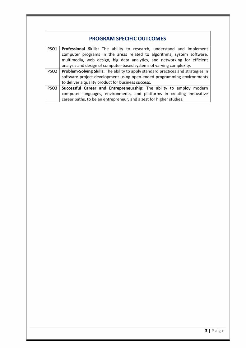
PROGRAM SPECIFIC OUTCOMES
PSO1 Professional Skills: The ability to research, understand and implement computer programs in the areas related to algorithms, system software, multimedia, web design, big data analytics, and networking for efficient analysis and design of computer-based systems of varying complexity.
PSO2 Problem-Solving Skills: The ability to apply standard practices and strategies in software project development using open-ended programming environments to deliver a quality product for business success.
PSO3 Successful Career and Entrepreneurship: The ability to employ modern computer languages, environments, and platforms in creating innovative career paths, to be an entrepreneur, and a zest for higher studies.
4 | P a g e
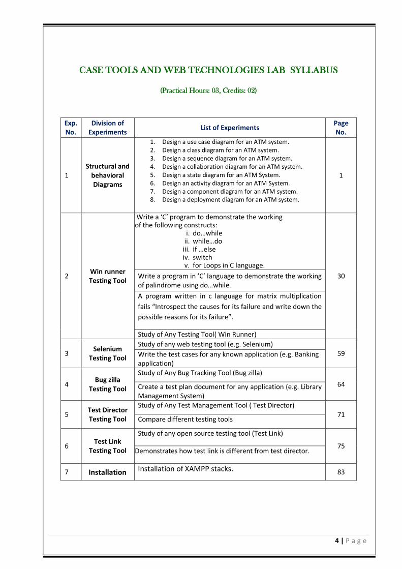
CASE TOOLS AND WEB TECHNOLOGIES LAB SYLLABUS
(Practical Hours: 03, Credits: 02)
Exp. No.
Division of Experiments
List of Experiments Page No.
1 Structural and
behavioral Diagrams
1. Design a use case diagram for an ATM system. 2. Design a class diagram for an ATM system. 3. Design a sequence diagram for an ATM system. 4. Design a collaboration diagram for an ATM system. 5. Design a state diagram for an ATM System. 6. Design an activity diagram for an ATM System. 7. Design a component diagram for an ATM system. 8. Design a deployment diagram for an ATM system.
1
2 Win runner Testing Tool
Write a ‘C’ program to demonstrate the working of the following constructs:
i. do…while ii. while…do iii. if …else iv. switch v. for Loops in C language.
30 Write a program in ’C’ language to demonstrate the working of palindrome using do…while.
A program written in c language for matrix multiplication
fails “Introspect the causes for its failure and write down the
possible reasons for its failure”.
Study of Any Testing Tool( Win Runner)
3 Selenium
Testing Tool
Study of any web testing tool (e.g. Selenium) 59 Write the test cases for any known application (e.g. Banking
application)
4 Bug zilla
Testing Tool
Study of Any Bug Tracking Tool (Bug zilla)
64 Create a test plan document for any application (e.g. Library Management System)
5 Test Director Testing Tool
Study of Any Test Management Tool ( Test Director) 71
Compare different testing tools
6 Test Link
Testing Tool
Study of any open source testing tool (Test Link)
75 Demonstrates how test link is different from test director.
7 Installation Installation of XAMPP stacks. 83
5 | P a g e
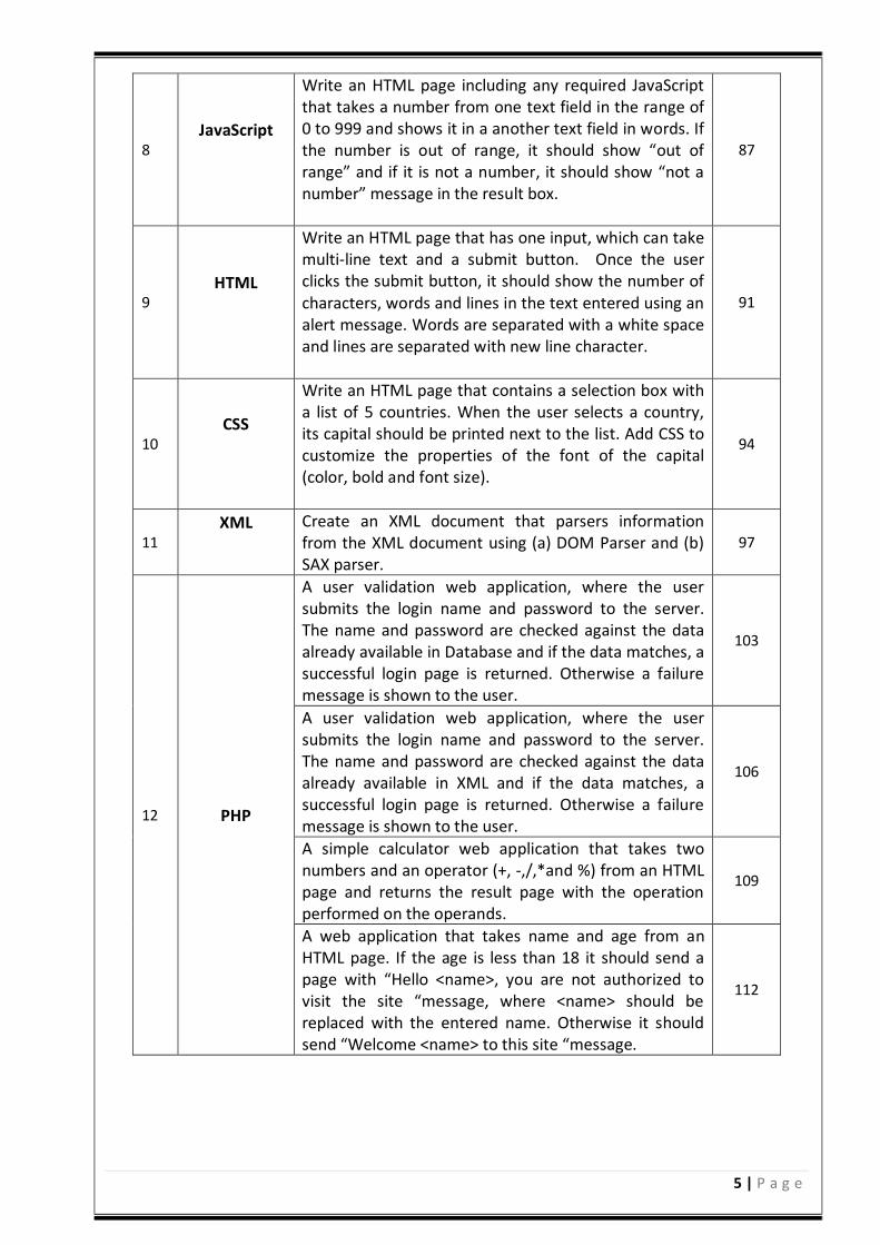
8 JavaScript
Write an HTML page including any required JavaScript that takes a number from one text field in the range of 0 to 999 and shows it in a another text field in words. If the number is out of range, it should show “out of range” and if it is not a number, it should show “not a number” message in the result box.
87
9 HTML
Write an HTML page that has one input, which can take multi-line text and a submit button. Once the user clicks the submit button, it should show the number of characters, words and lines in the text entered using an alert message. Words are separated with a white space and lines are separated with new line character.
91
10 CSS
Write an HTML page that contains a selection box with a list of 5 countries. When the user selects a country, its capital should be printed next to the list. Add CSS to customize the properties of the font of the capital (color, bold and font size).
94
11 XML
Create an XML document that parsers information from the XML document using (a) DOM Parser and (b) SAX parser.
97
12 PHP
A user validation web application, where the user submits the login name and password to the server. The name and password are checked against the data already available in Database and if the data matches, a successful login page is returned. Otherwise a failure message is shown to the user.
103
A user validation web application, where the user submits the login name and password to the server. The name and password are checked against the data already available in XML and if the data matches, a successful login page is returned. Otherwise a failure message is shown to the user.
106
A simple calculator web application that takes two numbers and an operator (+, -,/,*and %) from an HTML page and returns the result page with the operation performed on the operands.
109
A web application that takes name and age from an HTML page. If the age is less than 18 it should send a page with “Hello <name>, you are not authorized to visit the site “message, where <name> should be replaced with the entered name. Otherwise it should send “Welcome <name> to this site “message.
112
6 | P a g e
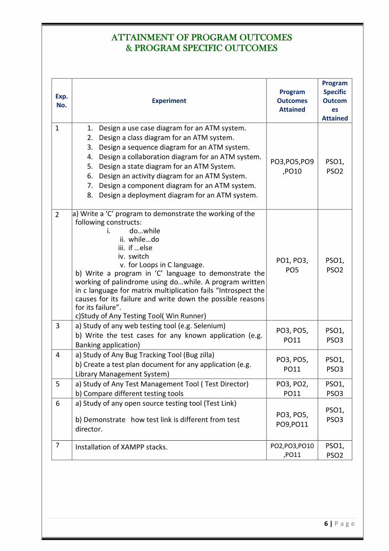
ATTAINMENT OF PROGRAM OUTCOMES
& PROGRAM SPECIFIC OUTCOMES
Exp. No.
Experiment Program
Outcomes Attained
Program Specific Outcom
es Attained
1 1. Design a use case diagram for an ATM system. 2. Design a class diagram for an ATM system. 3. Design a sequence diagram for an ATM system. 4. Design a collaboration diagram for an ATM system. 5. Design a state diagram for an ATM System. 6. Design an activity diagram for an ATM System. 7. Design a component diagram for an ATM system. 8. Design a deployment diagram for an ATM system.
PO3,PO5,PO9,PO10
PSO1, PSO2
2 a) Write a ‘C’ program to demonstrate the working of the following constructs:
i. do…while ii. while…do iii. if …else iv. switch v. for Loops in C language.
b) Write a program in ’C’ language to demonstrate the working of palindrome using do…while. A program written in c language for matrix multiplication fails “Introspect the causes for its failure and write down the possible reasons for its failure”. c)Study of Any Testing Tool( Win Runner)
PO1, PO3, PO5
PSO1, PSO2
3 a) Study of any web testing tool (e.g. Selenium) b) Write the test cases for any known application (e.g. Banking application)
PO3, PO5, PO11
PSO1, PSO3
4 a) Study of Any Bug Tracking Tool (Bug zilla) b) Create a test plan document for any application (e.g. Library Management System)
PO3, PO5, PO11
PSO1, PSO3
5 a) Study of Any Test Management Tool ( Test Director) b) Compare different testing tools
PO3, PO2, PO11
PSO1, PSO3
6 a) Study of any open source testing tool (Test Link)
b) Demonstrate how test link is different from test director.
PO3, PO5, PO9,PO11
PSO1, PSO3
7 Installation of XAMPP stacks. PO2,PO3,PO10,PO11
PSO1, PSO2
7 | P a g e
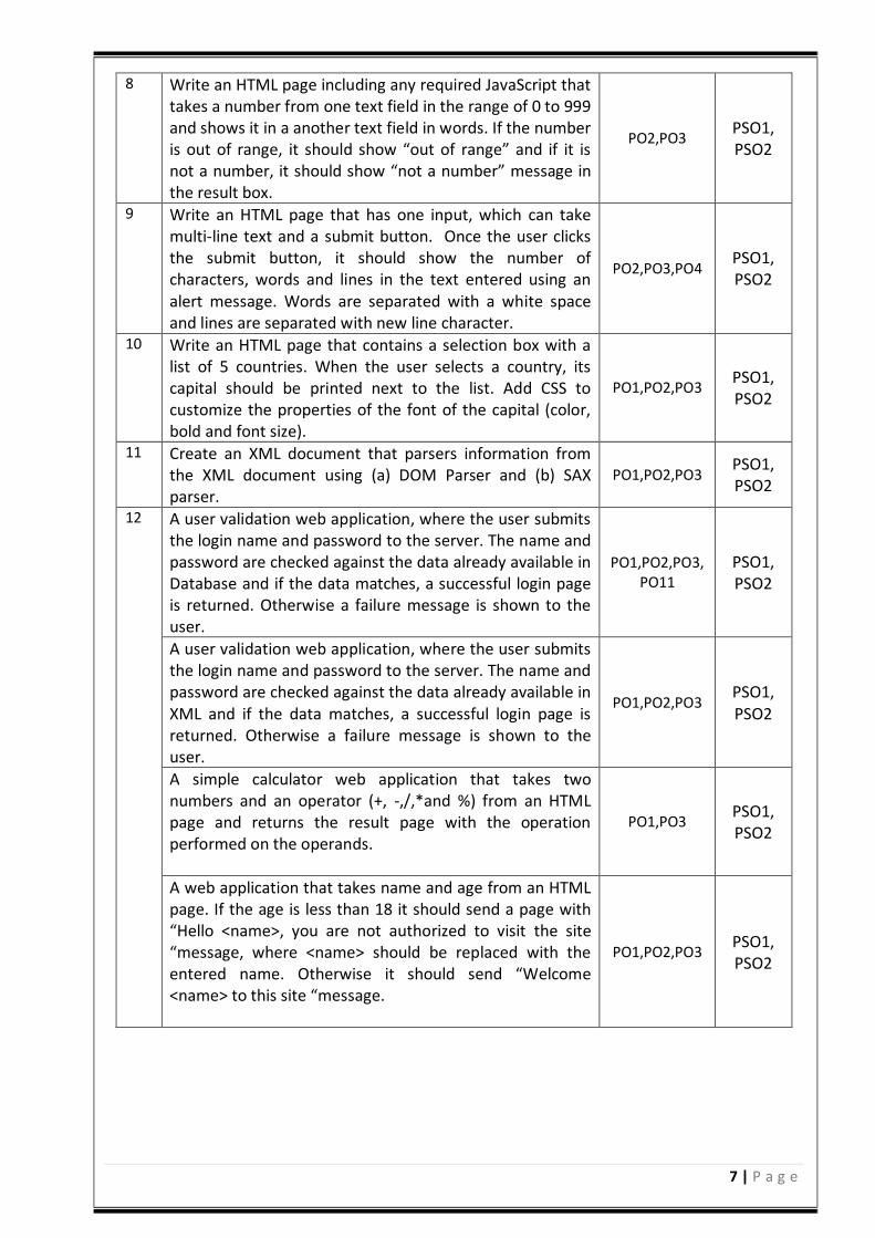
8 Write an HTML page including any required JavaScript that takes a number from one text field in the range of 0 to 999 and shows it in a another text field in words. If the number is out of range, it should show “out of range” and if it is not a number, it should show “not a number” message in the result box.
PO2,PO3 PSO1, PSO2
9 Write an HTML page that has one input, which can take multi-line text and a submit button. Once the user clicks the submit button, it should show the number of characters, words and lines in the text entered using an alert message. Words are separated with a white space and lines are separated with new line character.
PO2,PO3,PO4 PSO1, PSO2
10 Write an HTML page that contains a selection box with a list of 5 countries. When the user selects a country, its capital should be printed next to the list. Add CSS to customize the properties of the font of the capital (color, bold and font size).
PO1,PO2,PO3 PSO1, PSO2
11 Create an XML document that parsers information from the XML document using (a) DOM Parser and (b) SAX parser.
PO1,PO2,PO3 PSO1, PSO2
12 A user validation web application, where the user submits the login name and password to the server. The name and password are checked against the data already available in Database and if the data matches, a successful login page is returned. Otherwise a failure message is shown to the user.
PO1,PO2,PO3,PO11
PSO1, PSO2
A user validation web application, where the user submits the login name and password to the server. The name and password are checked against the data already available in XML and if the data matches, a successful login page is returned. Otherwise a failure message is shown to the user.
PO1,PO2,PO3 PSO1, PSO2
A simple calculator web application that takes two numbers and an operator (+, -,/,*and %) from an HTML page and returns the result page with the operation performed on the operands.
PO1,PO3 PSO1, PSO2
A web application that takes name and age from an HTML page. If the age is less than 18 it should send a page with “Hello <name>, you are not authorized to visit the site “message, where <name> should be replaced with the entered name. Otherwise it should send “Welcome <name> to this site “message.
PO1,PO2,PO3 PSO1, PSO2
8 | P a g e
CASE TOOLS LAB
9 | P a g e
CASE TOOLS LABORATORY
LABORATORY OVERVIEW:
OOAD is an essential stage of SDLC which needs to be taken up as part of the software
development process. Students practice on various methods of Diagrams in this lab through
Designing tools like Rational Rose. The objective of the Case tools lab is to gain the Modeling
skills on how to use Designing tools to support software projects.
OBJECTIVES: The objectives of this laboratory are:
1. Understand how UML supports the entire OOAD process.
2. Become familiar with all phases of OOAD.
3. Be able to understand the essential characteristics of tools used for Designing a model.
OUTCOMES: Upon the completion of practical course Case tools Lab, the student will be able to attain the following things:
1. Able to understand the history, cost of using and building CASE tools.
2. Ability to construct and evaluate hybrid CASE tools by integrating existing tools.
10 | P a g e
EXPERIMENT 1
1.1 OBJECTIVE: Generate Use case Diagram for ATM System 1.2 RESOURCES:
1. A working computer system with either Windows or Linux.
2. Rational Rose Software or Visual Paradigm Software.
1.3 DESCRIPTION:
The purpose of use case diagram is to capture the dynamic aspect of a system. But this definition is too
generic to describe the purpose. Because other four diagrams (activity, sequence, collaboration and State
chart) are also having the same purpose. So we will look into some specific purpose which will distinguish it
from other four diagrams. Use case diagrams are used to gather the requirements of a system including
internal and external influences. These requirements are mostly design requirements. So when a system is
analyzed to gather its functionalities use cases are prepared and actors are identified.
So in brief, the purposes of use case diagrams can be as follows:
Used to gather requirements of a system. Used to get an outside view of a system. Identify external and internal factors influencing the system. Show the interacting among the requirements are actors
Withdrawal Use Case:
A withdrawal transaction asks the customer to choose a type of account to withdraw from (e.g. checking)
from a menu of possible accounts, and to choose a dollar amount from a menu of possible amounts. The
system verifies that it has sufficient money on hand to satisfy the request before sending the transaction to
the bank. (If not, the customer is informed and asked to enter a different amount.) If the transaction is
approved by the bank, the appropriate amount of cash is dispensed by the machine before it issues a receipt.
A withdrawal transaction can be can-celled by the customer pressing the Cancel key any time prior to
choosing the dollar amount.
Deposit Use Case: A deposit transaction asks the customer to choose a type of account to deposit to (e.g. checking) from a
menu of possible accounts, and to type in a dollar amount on the keyboard. The transaction is initially sent to
the bank to verify that the ATM can accept a deposit from this customer to this account. If the transaction is
approved, the machine accepts an envelope from the customer containing cash and/or checks before it
issues a receipt. Once the envelope has been received, a second message is sent to the bank, to confirm that
the bank can credit the customer‘s account – contingent on manual verification of the deposit envelope
contents by an operator later. A deposit transaction can be cancelled by the customer pressing the Cancel key any time prior to inserting

11 | P a g e
the envelope containing the deposit. The transaction is automatically cancelled if the customer fails to insert
the envelope containing the deposit within a reasonable period of time after being asked to do so.
Transfer Use Case: A transfer transaction asks the customer to choose a type of account to transfer from (e.g. checking) from a
menu of possible accounts, to choose a different account to transfer to, and to type in a dollar amount on the
keyboard. No further action is required once the transaction is approved by the bank before printing the
receipt. A transfer transaction can be cancelled by the customer pressing the Cancel key any time prior to
entering a dollar amount.
Inquiry Use Case: An inquiry transaction asks the customer to choose a type of account to inquire about from a menu of
possible accounts. No further action is required once the transaction is approved by the bank before printing
the receipt. An inquiry transaction can be cancelled by the customer pressing the Cancel key any time prior to
choosing the account to inquire about.
Validate User use case: This use case is for validate the user i.e. check the pin number, when the bank reports that the customer‘s
transaction is disapproved due to an invalid PIN. The customer is required to re-enter the PIN and the original
request is sent to the bank again. If the bank now approves the transaction, or disapproves it for some other
reason, the original use case is continued; otherwise the process of re-entering the PIN is repeated. Once the
PIN is successfully re-entered.
If the customer fails three times to enter the correct PIN, the card is permanently retained, a screen is
displayed informing the customer of this and suggesting he/she contact the bank, and the entire customer
session is aborted.
Print Bill use case: This use case is for printing corresponding bill after transactions (withdraw or deposit ,or balance enquiry, transfer) are completed.
Update Account: This use case is for updating corresponding user accounts after transactions (withdraw or deposit or transfer) are completed.
1.4 PROCEDURE:
1. Open folder Use Case View. Name your use case diagram.
2. Double click on the Use Case View icon or right click on Use Case View and select Open.
3. Now click on the icon for actor and draw an actor on use case view diagram. Actor will represent your user or the client, which will interact with your system.
4. Now click on the icon for use case and draw use cases for the system.
5. Now click on the appropriate arrow for the relation between actor and use case.
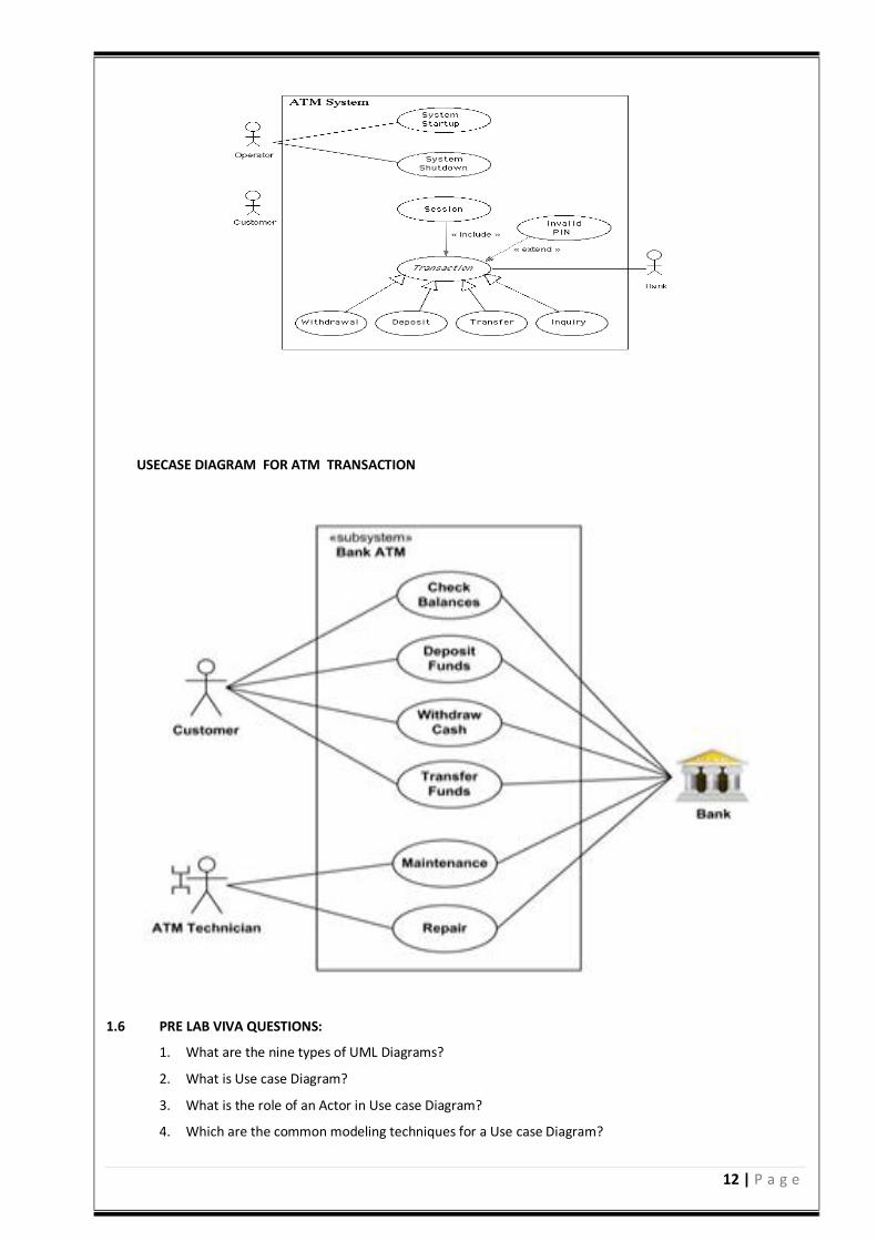
6. Click on the package and show appropriate relation among these three entities. 1.5 A. USE CASE DIAGRAM FOR ATM
12 | P a g e
USECASE DIAGRAM FOR ATM TRANSACTION
1.6 PRE LAB VIVA QUESTIONS:
1. What are the nine types of UML Diagrams?
2. What is Use case Diagram?
3. What is the role of an Actor in Use case Diagram?
4. Which are the common modeling techniques for a Use case Diagram?
13 | P a g e
5. What are the different relationships used in Use case Diagram? 1.7 LAB ASSIGNMENT:
1. Identify actors in Airport check-in and security screening business model?
2. Design a Use case diagram for restaurant?
3. Show that ticket vending machine allows from commuters to buy tickets using Use case Diagram?
4. Design Use case Diagram for e-library online public access catalog?
5. Define major Use cases for a credit card processing system?
1.8 POST LAB VIVA QUESTIONS:
1. What are main flow of events and exception flow of events in use cases ?
2. How Use cases realize collaborations?
3. What are extend and include stereotypes?
4. Can we organize use cases into packages?
5. How to forward engineering and reverse engineering in Use case Diagram?
2.1 OBJECTIVE: Generate a Class Diagram for ATM System. 2.2 RESOURCES:
1. A working computer system with either Windows or Linux. 2. Rational Rose Software or Visual Paradigm Software.
2.3 DESCRIPTION:
The purpose of the class diagram is to model the static view of an application. The class diagrams are the
only diagrams which can be directly mapped with object oriented languages and thus widely used at the
time of construction. The UML diagrams like activity diagram, sequence diagram can only give the
sequence flow of the application but class diagram is a bit different. So it is the most popular UML diagram
in the coder community. So the purpose of the class diagram can be summarized as:
Analysis and design of the static view of an application. Describe responsibilities of a system. Base for component and deployment diagrams. Forward and reverse engineering.
Contents: Class diagrams commonly contain the following things
Classes Interfaces Collaborations Dependency, generalization and association relationships
2.4 PROCEDURE:
1. The Logical View Class Diagram window may already be open. If so, skip to step 3.
2. Open the Logical View Folder. Double click on the icon next to Main. (Alternately, right click
on Main and select Open).
3. To draw a class, click on the class icon on the toolbar. Move the cross bar to the class diagram
14 | P a g e
window and click.
4. Name the class. Note that you do not want to use the same name as an Actor in your Use Case
diagram. For example, if you have a Student actor, the class should be named Student Proxy.
5. Now right click on the class to add attributes and methods to your class.
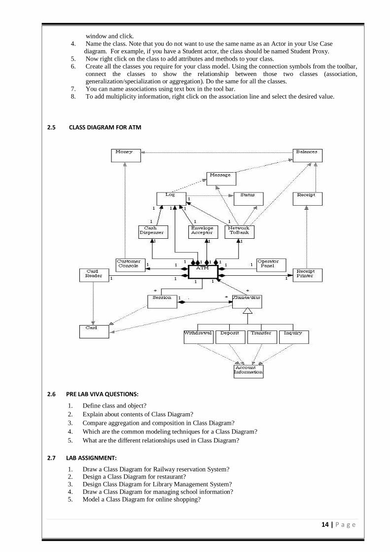
6. Create all the classes you require for your class model. Using the connection symbols from the toolbar,
connect the classes to show the relationship between those two classes (association, generalization/specialization or aggregation). Do the same for all the classes.
7. You can name associations using text box in the tool bar.
8. To add multiplicity information, right click on the association line and select the desired value.
2.5 CLASS DIAGRAM FOR ATM
2.6 PRE LAB VIVA QUESTIONS:
1. Define class and object?
2. Explain about contents of Class Diagram?
3. Compare aggregation and composition in Class Diagram?
4. Which are the common modeling techniques for a Class Diagram?
5. What are the different relationships used in Class Diagram?
2.7 LAB ASSIGNMENT:
1. Draw a Class Diagram for Railway reservation System? 2. Design a Class Diagram for restaurant?
3. Design Class Diagram for Library Management System?
4. Draw a Class Diagram for managing school information?
5. Model a Class Diagram for online shopping?
15 | P a g e
2.8 POST LAB VIVA QUESTIONS:
1. How Interfaces are implemented by classes?
2. Explain about structural diagrams?
3. How to model logical database schema?
4. Explain modeling of a distributed system using class and collaboration?
5. What is meant by responsibilities?
3.1 OBJECTIVE: Generate a Sequence Diagram for ATM System. 3.2 RESOURCES:
1. A working computer system with either Windows or Linux. 2. Rational Rose Software or Visual Paradigm Software.
3.3 DESCRIPTION:
We have two types of interaction diagrams in UML. One is sequence diagram and the other is a
collaboration diagram. The sequence diagram captures the time sequence of message flow from one object
to another and the collaboration diagram describes the organization of objects in a system taking part in
the message flow.
So the following things are to identified clearly before drawing the interaction diagram:
1. Objects taking part in the interaction. 2. Message flows among the objects. 3. The sequence in which the messages are flowing. 4. Object organization.
Purpose:
1. To capture dynamic behavior of a system. 2. To describe the message flow in the system. 3. To describe structural organization of the objects. 4. To describe interaction among objects.
Contents of a Sequence Diagram
a. Objects b. Focus of control c. Messages d. Life line e. Contents
3.4 PROCEDURE:
1. From Use Case View, Click to highlight the Use Case name. 2. Right click and select New. 3. Select Sequence Diagram and type a name for the diagram in the browser. 4. You can now double click the icon next the name to open the sequence diagram window.
16 | P a g e
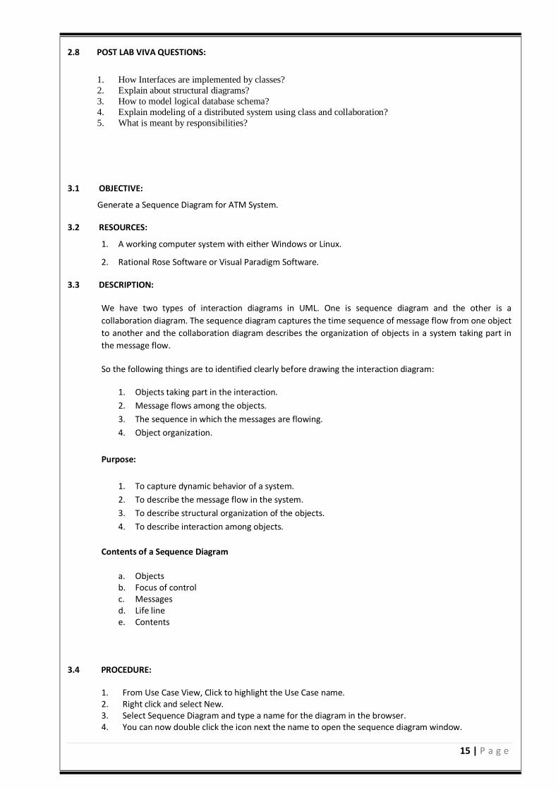
5. To put actors on the sequence diagram, in the browser, under Use Case View, click on the desired actor and drag it onto the sequence diagram window.
6. To put objects on the sequence diagram, in the browser, under Logical View, click on the desired class and drag it onto the sequence diagram window.
7. Note that if you use the toolbar to put an object on the sequence diagram, the tool will ask you for its class. If the class doesn’t exist in your Logical View, you will have to create it.
8. The tool will place your actors and objects from left to right in the order you select them. Once they are in the window, you can rearrange in the usual manner.
9. To add a message in the toolbar, select the message arrow, Click on the lifeline of the source of the message and drag to the lifeline of the destination of the message.
10. To add a message name, Right click on the message arrow. You can either select one of the existing messages, or select <new operation> to add a new message.
3.5 A. SEQUENCE DIAGRAM FOR ATM
17 | P a g e
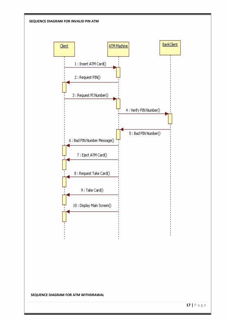
SEQUENCE DIAGRAM FOR INVALID PIN ATM
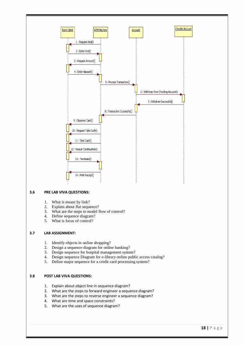
SEQUENCE DIAGRAM FOR ATM WITHDRAWAL
18 | P a g e
3.6 PRE LAB VIVA QUESTIONS:
1. What is meant by link?
2. Explain about flat sequence?
3. What are the steps to model flow of control? 4. Define sequence diagram?
5. What is focus of control?
3.7 LAB ASSIGNMENT:
1. Identify objects in online shopping?
2. Design a sequence diagram for online banking?
3. Design sequence for hospital management system?
4. Design sequence Diagram for e-library online public access catalog?
5. Define major sequence for a credit card processing system?
3.8 POST LAB VIVA QUESTIONS:
1. Explain about object line in sequence diagram? 2. What are the steps to forward engineer a sequence diagram? 3. What are the steps to reverse engineer a sequence diagram? 4. What are time and space constraints? 5. What are the uses of sequence diagram?
19 | P a g e
4.1 OBJECTIVE: Generate a Collaboration Diagram for ATM System. 4.2 RESOURCES:
1. A working computer system with either Windows or Linux.
2. Rational Rose Software or Visual Paradigm Software.
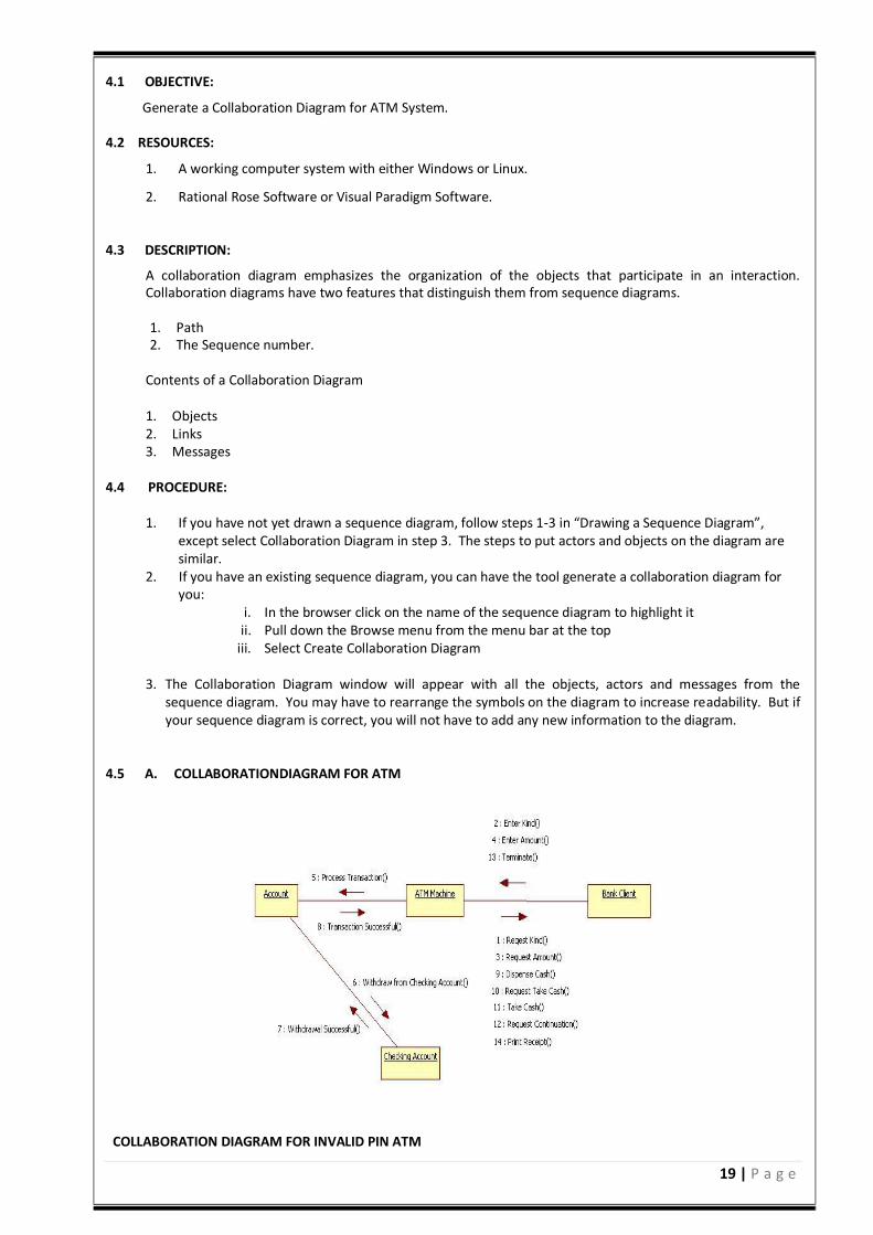
4.3 DESCRIPTION:
A collaboration diagram emphasizes the organization of the objects that participate in an interaction. Collaboration diagrams have two features that distinguish them from sequence diagrams. 1. Path 2. The Sequence number.
Contents of a Collaboration Diagram 1. Objects 2. Links 3. Messages
4.4 PROCEDURE:
1. If you have not yet drawn a sequence diagram, follow steps 1-3 in “Drawing a Sequence Diagram”, except select Collaboration Diagram in step 3. The steps to put actors and objects on the diagram are similar.
2. If you have an existing sequence diagram, you can have the tool generate a collaboration diagram for you:
i. In the browser click on the name of the sequence diagram to highlight it ii. Pull down the Browse menu from the menu bar at the top
iii. Select Create Collaboration Diagram
3. The Collaboration Diagram window will appear with all the objects, actors and messages from the sequence diagram. You may have to rearrange the symbols on the diagram to increase readability. But if your sequence diagram is correct, you will not have to add any new information to the diagram.
4.5 A. COLLABORATIONDIAGRAM FOR ATM
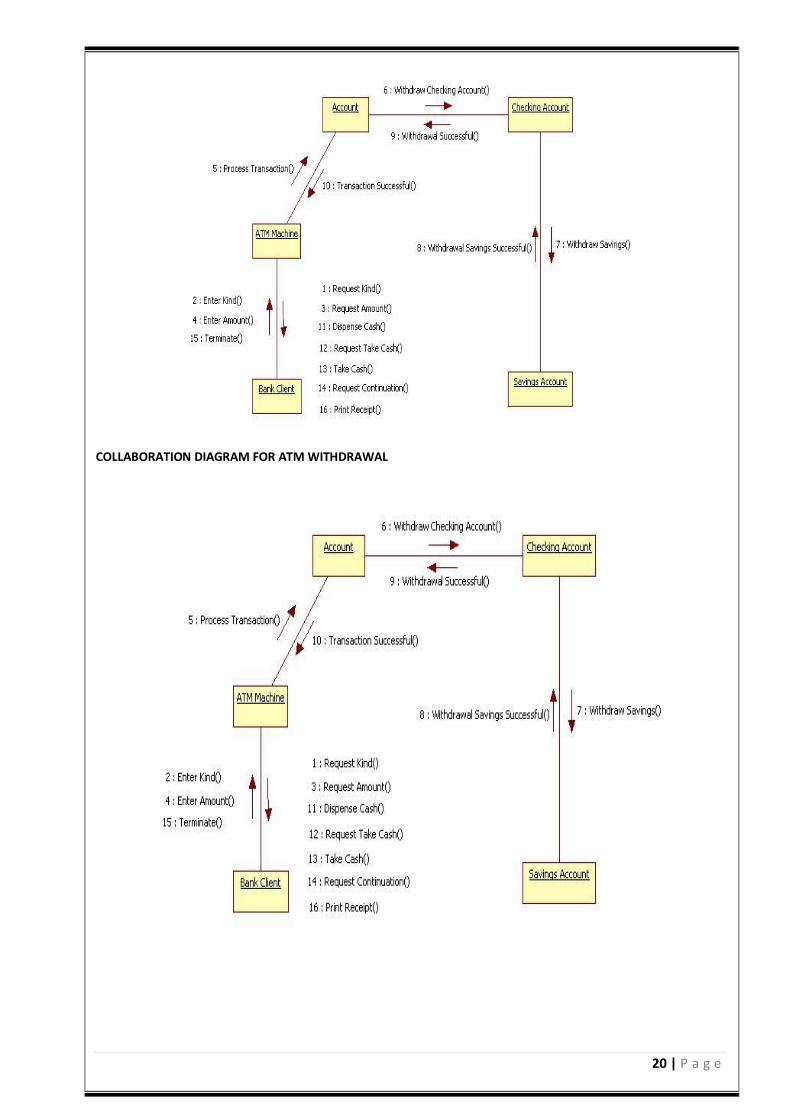
COLLABORATION DIAGRAM FOR INVALID PIN ATM
20 | P a g e
COLLABORATION DIAGRAM FOR ATM WITHDRAWAL
21 | P a g e
4.6 PRE LAB VIVA QUESTIONS:
1. Define interaction diagram? 2. Explain collaboration diagram?. 3. What are the uses of interaction diagram? 4. Explain modeling flow of organization? 5. What are the uses of collaboration diagram?
4.7 LAB ASSIGNMENT:
1. Draw a collaboration diagram for library management system? 2. Design objects in collaboration diagrams? 3. Design a collaboration diagram for hospital management system? 4. Draw a collaboration diagram for website administration system? 5. Draw a collaboration diagram for digital image communication?
4.8 POST LAB VIVA QUESTIONS:
1. How to model forward engineer a collaboration diagram? 2. What are the steps to reverse engineer a collaboration diagram? 3. Difference between sequence diagram and collaboration diagram ? 4. Compare become and copy stereotypes? 5. What are time and space constraints?
5.1 OBJECTIVE: Generate a State Diagram for ATM System. 5.2 RESOURCES:
1. A working computer system with either Windows or Linux.
2. Rational Rose Software or Visual Paradigm Software.
5.3 DESCRIPTIONS:
State chart diagram is used to model dynamic nature of a system. They define different states of an
object during its lifetime. And these states are changed by events. So State chart diagrams are useful to
model reactive systems. Reactive systems can be defined as a system that responds to external or
internal events.
State chart diagram describes the flow of control from one state to another state. States are defined as a
condition in which an object exists and it changes when some event is triggered. So the most important
purpose of State chart diagram is to model life time of an object from creation to termination.
State chart diagrams are also used for forward and reverse engineering of a system. But the main purpose is to model reactive system. Following are the main purposes of using State chart diagrams:
1. To model dynamic aspect of a system. 2. To model life time of a reactive system. 3. To describe different states of an object during its life time. 4. Define a state machine to model states of an object.
Contents
Simply state and composite states Transitions, including events and actions
Common use
They are used to model the dynamic aspects of a system. Event ordered behavior of any kind of objects, to model reactive objects.
22 | P a g e
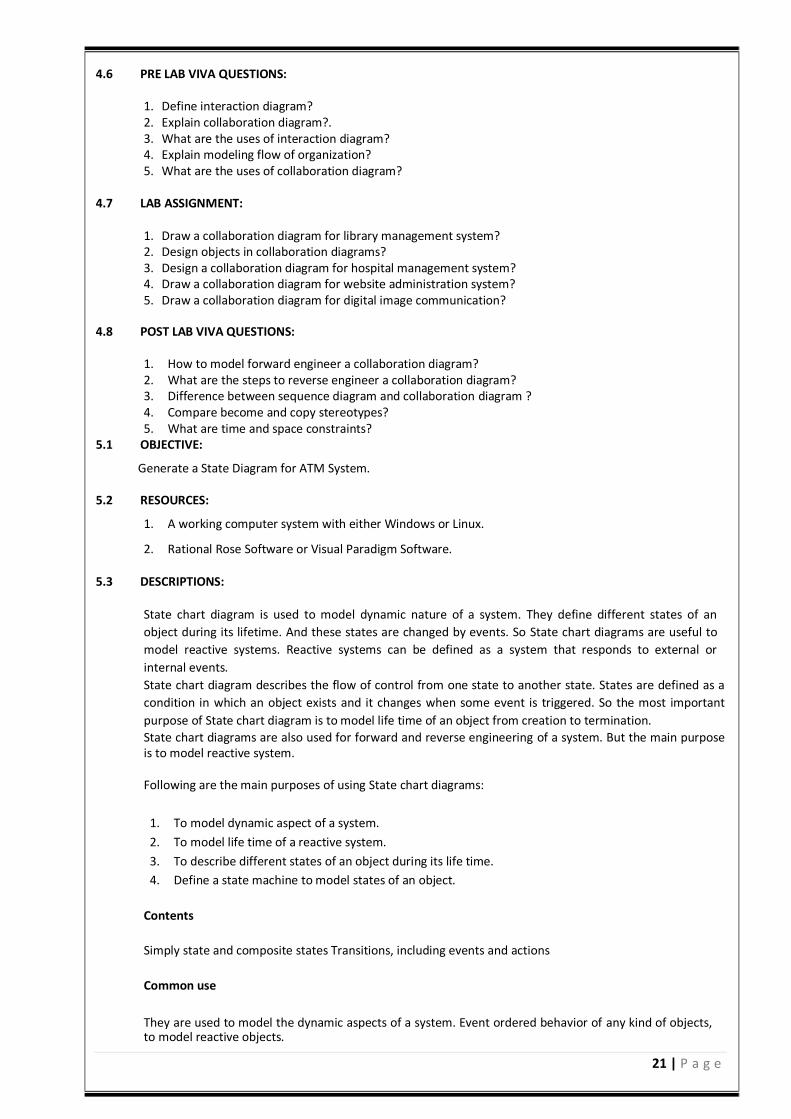
5.4 PROCEDURE:
1. Create a state machine when behavior differs based on state. a seminar object is fairly complex,
reacting to events such a enrolling a student differently depending on its current state.
2. Place the initial state in the top-left corner.
3. Place the final state in the bottom-right corner.
4. Model sub states for targeted complexity.
5.5 STATE DIAGRAM FOR ATM
23 | P a g e
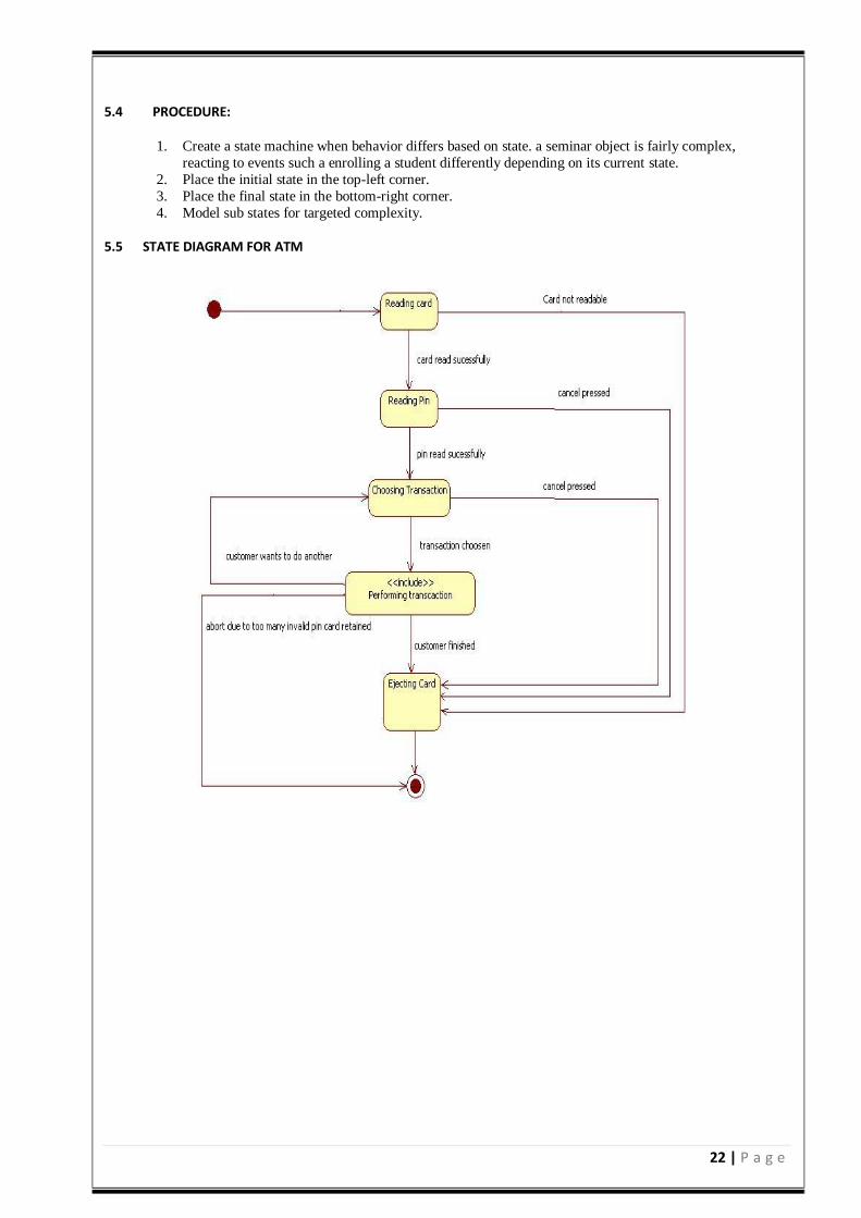
STATECHART DIAGRAM FOR VALIDATION
5.6 PRE LAB VIVA QUESTIONS:
1. Compare activity and action states? 2. Define action states? 3. What are transitions? 4. What are branches? 5. Compare fork and join?
5.7 LAB ASSIGNMENT:
1. Design water phase diagram using state chart diagram? 2. Draw state chart diagram for ATM state machine? 3. Design online shopping user account machine? 4. Draw state machine for ticket vending? 5. Design state machine for real estate business problem?
5.8 POST LAB VIVA QUESTIONS:
1. What are swim lanes? 2. How to model workflow in activity diagram? 3. How to model operations? 4. How to forward and reverse engineer an activity diagram? 5. What are the uses of an activity diagram?
6.1 OBJECTIVE: Generate an Activity Diagram for ATM System. 6.2 RESOURCES:
1. A working computer system with either Windows or Linux.
2. Rational Rose Software or Visual Paradigm Software.
24 | P a g e
6.3 DESCRIPTION:
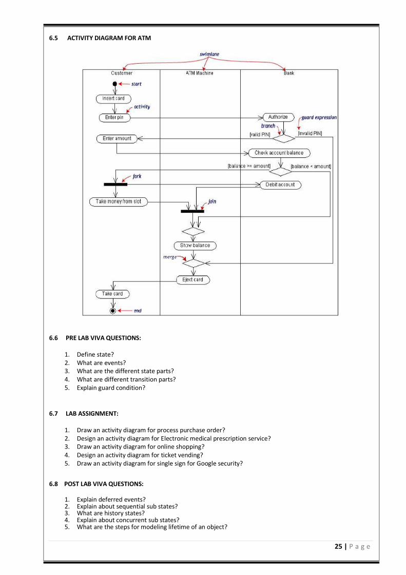
Activity diagram is basically a flow chart to represent the flow form one activity to another. The activity can
be described as an operation of the system. So the control flow is drawn from one operation to another. This
flow can be sequential, branched or concurrent. Activity diagrams deals with all type of flow by using
elements like fork join etc.
Contents
Initial/Final State, Activity , Fork & Join, Branch, Swim lanes.
Fork
A fork represents the splitting of a single flow of control into two or more concurrent flow of control. A fork
may have one incoming transition and two or more outgoing transitions, each of which represents an
independent flow of control. Below fork the activities associated with each of these path continues in
parallel.
Join
A join represents the synchronization of two or more concurrent flows of control. A join may have two or
more incoming transition and one outgoing transition. Above the join the activities associated with each of
these paths continues in parallel.
Branching
A branch specifies alternate paths takes based on some Boolean expression Branch is represented by
diamond Branch may have one incoming transition and two or more outgoing one on each outgoing
transition, you place a Boolean expression shouldn‘t overlap but they should cover all possibilities.
Swim lane:
Swim lanes are useful when we model workflows of business processes to partition the activity states on an
activity diagram into groups. Each group representing the business organization responsible for those
activities, these groups are called Swim lanes.
6.4 PROCEDURE:
1. Identify the scope of the activity diagram. 2. Add start and end points. 3. Add activities. 4. Add transitions from the activities. 5. Add decision points. 6. Identify opportunities for parallel activities.
25 | P a g e
6.5 ACTIVITY DIAGRAM FOR ATM
6.6 PRE LAB VIVA QUESTIONS:
1. Define state? 2. What are events? 3. What are the different state parts? 4. What are different transition parts? 5. Explain guard condition?
6.7 LAB ASSIGNMENT:
1. Draw an activity diagram for process purchase order? 2. Design an activity diagram for Electronic medical prescription service? 3. Draw an activity diagram for online shopping? 4. Design an activity diagram for ticket vending? 5. Draw an activity diagram for single sign for Google security?
6.8 POST LAB VIVA QUESTIONS:
1. Explain deferred events? 2. Explain about sequential sub states? 3. What are history states? 4. Explain about concurrent sub states? 5. What are the steps for modeling lifetime of an object?
26 | P a g e
7.1 OBJECTIVE: Generate a Component Diagram for ATM System. 7.2 RESOURCES:
1. A working computer system with either Windows or Linux. 2. Rational Rose Software or Visual Paradigm Software.
7.3 DESCRIPTION:
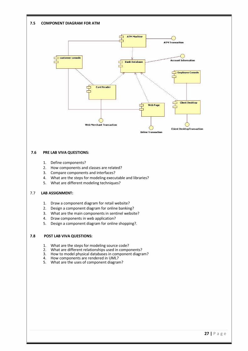
Component diagrams can be described as a static implementation view of a system. Static implementation
represents the organization of the components at a particular moment. A single component diagram cannot
represent the entire system but a collection of diagrams are used to represent the whole.
Before drawing a component diagram the following artifacts are to be identified clearly:
Files used in the system. Libraries and other artifacts relevant to the application. Relationships among the artifacts.
Now after identifying the artifacts the following points needs to be followed:
Use a meaningful name to identify the component for which the diagram is to be drawn. Prepare a mental layout before producing using tools. Use notes for clarifying important points.
Now the usage of component diagrams can be described as:
Model the components of a system. Model database schema. Model executable of an application. Model system‘s source code.
Contents
Components, Interfaces, Relationships. 7.4 PROCEDURE:
1. First component are created. 2. Packages are created. 3. Draw component s in the packages. 4. Draw the relationship between various components.
27 | P a g e
7.5 COMPONENT DIAGRAM FOR ATM
7.6 PRE LAB VIVA QUESTIONS:
1. Define components? 2. How components and classes are related? 3. Compare components and interfaces? 4. What are the steps for modeling executable and libraries? 5. What are different modeling techniques?
7.7 LAB ASSIGNMENT:
1. Draw a component diagram for retail website? 2. Design a component diagram for online banking? 3. What are the main components in sentinel website? 4. Draw components in web application? 5. Design a component diagram for online shopping?.
7.8 POST LAB VIVA QUESTIONS:
1. What are the steps for modeling source code? 2. What are different relationships used in components? 3. How to model physical databases in component diagram? 4. How components are rendered in UML? 5. What are the uses of component diagram?
28 | P a g e
8.1 OBJECTIVE: Generate a Deployment Diagram for ATM System. 8.2 RESOURCES:
1. A working computer system with either Windows or Linux.
2. Rational Rose Software or Visual Paradigm Software.
8.3 DESCRIPTION:
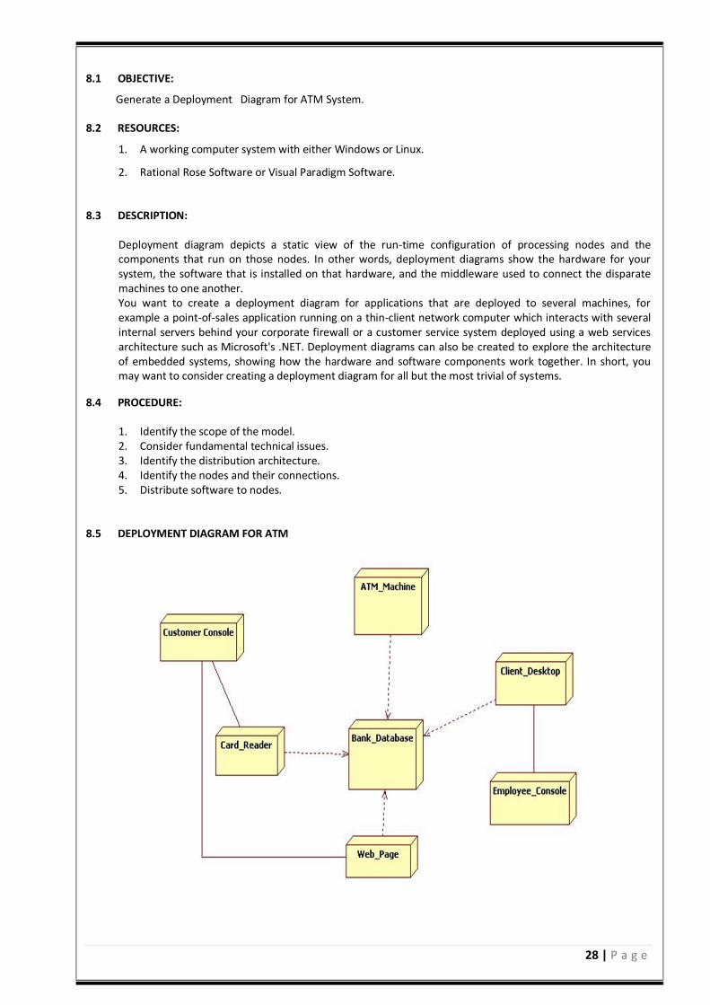
Deployment diagram depicts a static view of the run-time configuration of processing nodes and the components that run on those nodes. In other words, deployment diagrams show the hardware for your system, the software that is installed on that hardware, and the middleware used to connect the disparate machines to one another. You want to create a deployment diagram for applications that are deployed to several machines, for example a point-of-sales application running on a thin-client network computer which interacts with several internal servers behind your corporate firewall or a customer service system deployed using a web services architecture such as Microsoft's .NET. Deployment diagrams can also be created to explore the architecture of embedded systems, showing how the hardware and software components work together. In short, you may want to consider creating a deployment diagram for all but the most trivial of systems.
8.4 PROCEDURE:
1. Identify the scope of the model. 2. Consider fundamental technical issues. 3. Identify the distribution architecture. 4. Identify the nodes and their connections. 5. Distribute software to nodes.
8.5 DEPLOYMENT DIAGRAM FOR ATM
29 | P a g e
8.6 PRE LAB VIVA QUESTIONS:
1. Define node? 2. Compare node and components? 3. What are the contents of deployment diagrams? 4. How a node is rendered in UML? 5. How to model a fully distributed model?
8.7 LAB ASSIGNMENT:
1. Draw a deployment diagram for website application? 2. Design a deployment diagram for online banking? 3. What are the main nodes in clustered deployment J2ee website? 4. Draw deployment diagram in multi layered web balancing? 5. Design a deployment diagram for apple iTunes?
8.8 POST LAB VIVA QUESTIONS:
1. What are the steps to model embedded cod e? 2. What are the steps to model client server system? 3. Explain the uses of deployment diagram? 4. What are the different relationships used in deployment diagram? 5. What are modeling techniques of deployment diagrams?
30 | P a g e
SOFTWARE TESTING LAB
31 | P a g e
SOFTWARE TESTING LABORATORY
OBJECTIVE:
Testing is an essential stage of SDLC which needs to be taken up as part of the software development process. Students practice on various methods of software testing in this lab through testing tools like “Win Runner”, “Load Runner”, and QTP, in addition to the techniques of manual testing. The objective of the software testing lab is to gain the techniques and skills on how to use modern software testing tools to support software testing projects.
OUTCOMES: Upon the completion of Operating Systems practical course, the student will be able to:
1. Analyze any system and study its system specifications and report the various bugs 2. Simulate test cases for a software project using different testing and tracking tools.
3. Understand and analyze different testing tools and their mechanisms.
4. Understand the benefits of win runner, selenium and Bug zilla.
5. Analyze different testing tools like test director and test link for web testing and bug tracking.
30 | P a g e
SOFTWARE TESTING LABORATORY
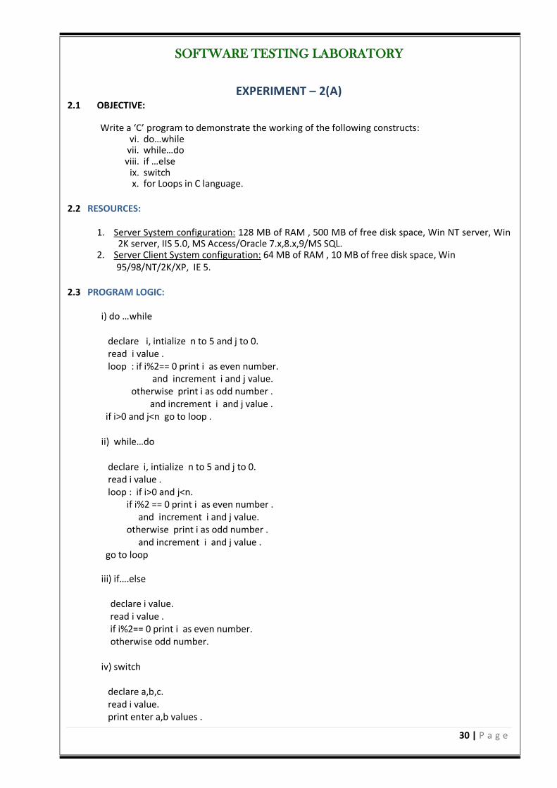
EXPERIMENT – 2(A) 2.1 OBJECTIVE:
Write a ‘C’ program to demonstrate the working of the following constructs:
vi. do…while vii. while…do viii. if …else
ix. switch x. for Loops in C language.
2.2 RESOURCES:
1. Server System configuration: 128 MB of RAM , 500 MB of free disk space, Win NT server, Win
2K server, IIS 5.0, MS Access/Oracle 7.x,8.x,9/MS SQL. 2. Server Client System configuration: 64 MB of RAM , 10 MB of free disk space, Win
95/98/NT/2K/XP, IE 5.
2.3 PROGRAM LOGIC:
i) do …while declare i, intialize n to 5 and j to 0. read i value . loop : if i%2== 0 print i as even number. and increment i and j value. otherwise print i as odd number . and increment i and j value . if i>0 and j<n go to loop . ii) while…do declare i, intialize n to 5 and j to 0. read i value . loop : if i>0 and j<n. if i%2 == 0 print i as even number . and increment i and j value. otherwise print i as odd number . and increment i and j value . go to loop iii) if….else declare i value. read i value . if i%2== 0 print i as even number. otherwise odd number. iv) switch declare a,b,c. read i value. print enter a,b values .
31 | P a g e
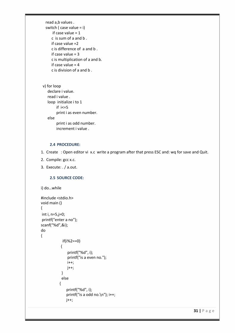
read a,b values . switch ( case value = i) if case value = 1 c is sum of a and b . if case value =2 c is difference of a and b . if case value = 3 c is multiplication of a and b. if case value = 4 c is division of a and b . v) for loop declare i value. read i value . loop initialize i to 1 if i<=5 print i as even number. else print i as odd number. increment i value .
2.4 PROCEDURE:
1. Create : Open editor vi x.c write a program after that press ESC and: wq for save and Quit. 2. Compile: gcc x.c. 3. Execute: . / a.out.
2.5 SOURCE CODE:
i) do…while #include <stdio.h> void main () int i, n=5,j=0; printf(“enter a no”); scanf(“%d”,&i); do if(i%2==0)
printf("%d", i); printf("is a even no."); i++; j++; else printf("%d", i); printf("is a odd no.\n"); i++; j++;
32 | P a g e
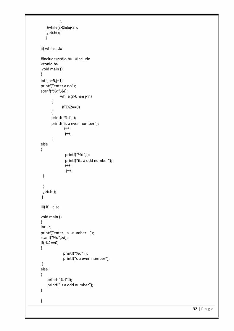
while(i>0&&j<n); getch(); ii) while…do #include<stdio.h> #include <conio.h> void main () int i,n=5,j=1; printf(“enter a no”); scanf(“%d”,&i);
while (i>0 && j<n) if(i%2==0) printf(“%d”,i); printf(“is a even number”); i++; j++;
else printf(“%d”,i); printf(“its a odd number”); i++; j++;
getch(); iii) if….else void main () int I,c; printf(“enter a number “); scanf(“%d”,&i); if(i%2==0) printf(“%d”,i); printf(“s a even number”);
else printf(“%d”,i); printf(“is a odd number”);
33 | P a g e
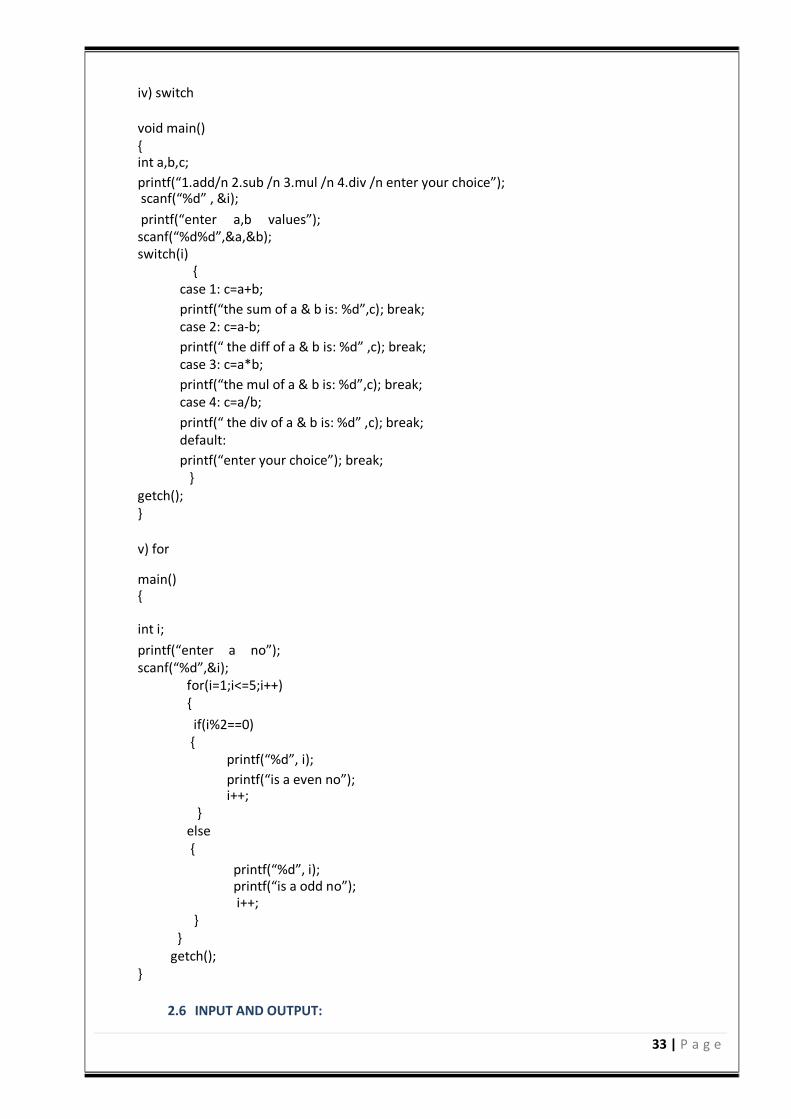
iv) switch void main() int a,b,c; printf(“1.add/n 2.sub /n 3.mul /n 4.div /n enter your choice”); scanf(“%d” , &i); printf(“enter a,b values”); scanf(“%d%d”,&a,&b); switch(i)
case 1: c=a+b; printf(“the sum of a & b is: %d”,c); break; case 2: c=a-b; printf(“ the diff of a & b is: %d” ,c); break; case 3: c=a*b; printf(“the mul of a & b is: %d”,c); break; case 4: c=a/b; printf(“ the div of a & b is: %d” ,c); break; default: printf(“enter your choice”); break;
getch(); v) for main() int i; printf(“enter a no”); scanf(“%d”,&i); for(i=1;i<=5;i++) if(i%2==0) printf(“%d”, i); printf(“is a even no”); i++; else printf(“%d”, i); printf(“is a odd no”); i++; getch();
2.6 INPUT AND OUTPUT:
34 | P a g e
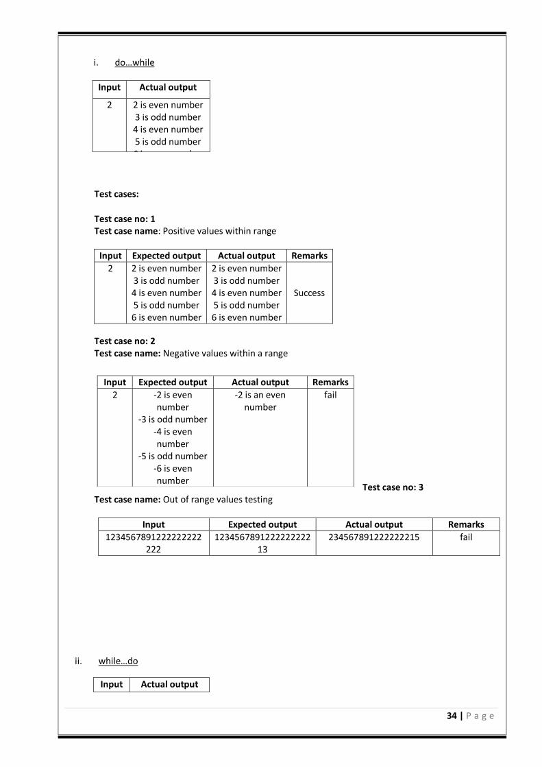
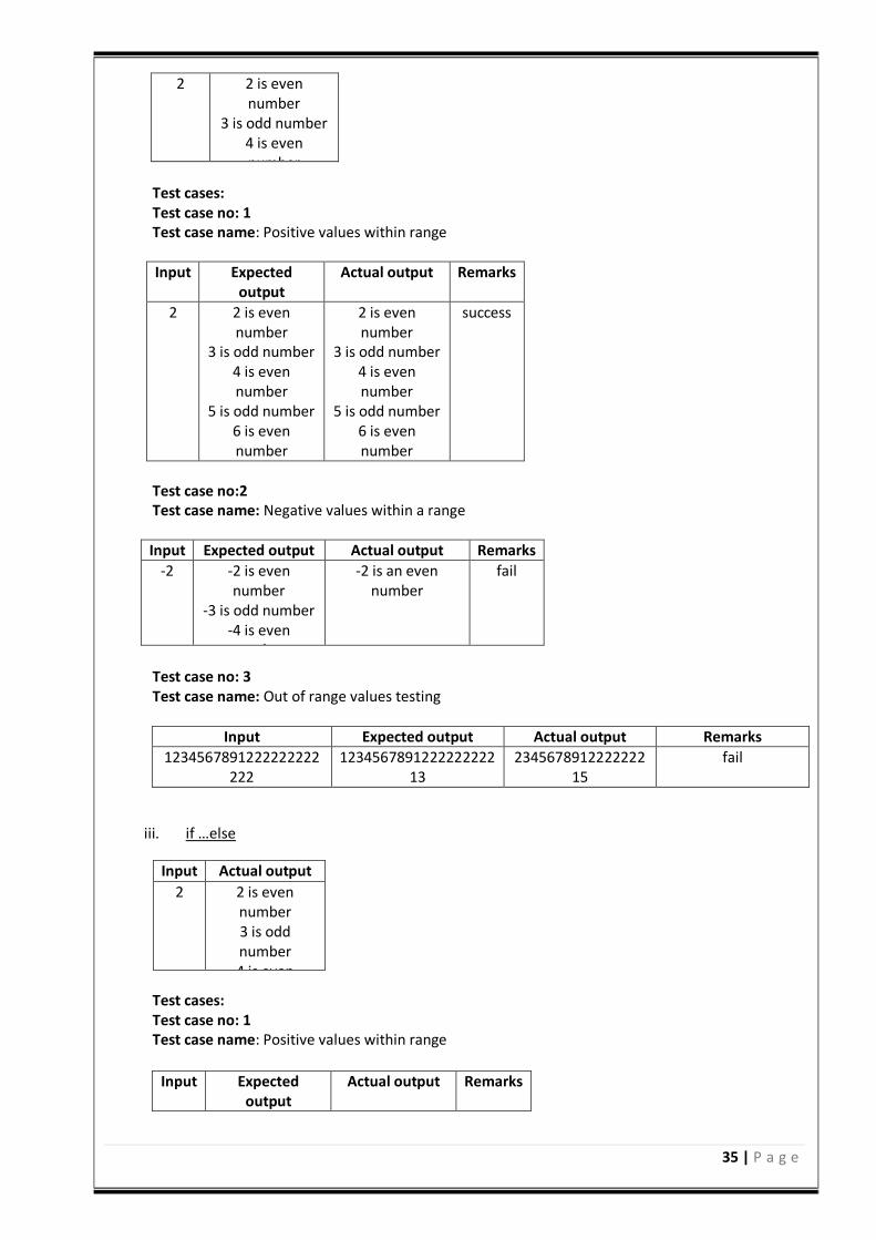
i. do…while Test cases:
Test case no: 1 Test case name: Positive values within range
Input Expected output Actual output Remarks
2 2 is even number 3 is odd number 4 is even number 5 is odd number 6 is even number
2 is even number 3 is odd number 4 is even number 5 is odd number 6 is even number
Success
Test case no: 2 Test case name: Negative values within a range
Test case no: 3 Test case name: Out of range values testing
Input Expected output Actual output Remarks
1234567891222222222222
123456789122222222213
234567891222222215 fail
ii. while…do
Input
Actual output
Input
Actual output
2 2 is even number 3 is odd number 4 is even number 5 is odd number 6 is even number
Input Expected output Actual output Remarks
2 -2 is even number
-3 is odd number -4 is even number
-5 is odd number -6 is even number
-2 is an even number
fail
35 | P a g e
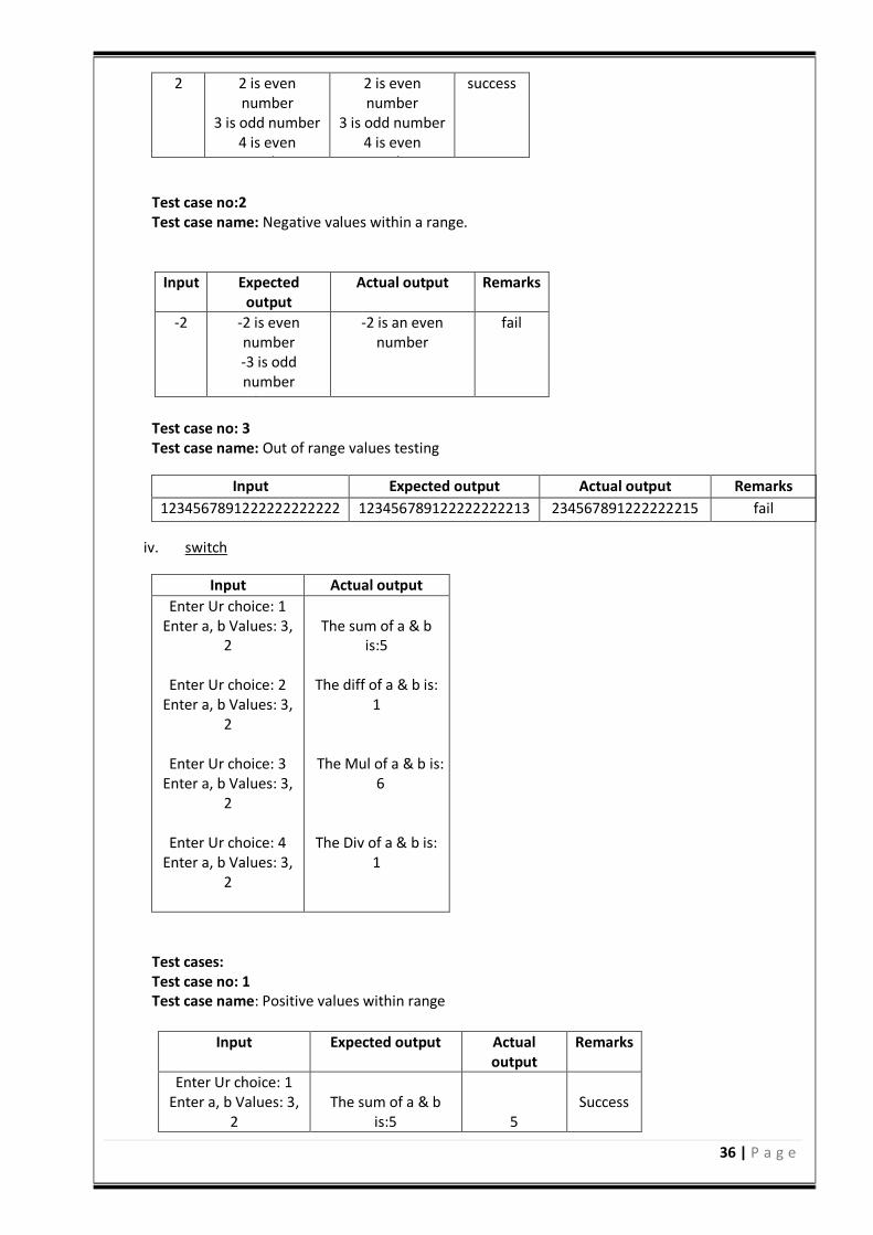
2 2 is even number
3 is odd number 4 is even number
5 is odd number 6 is even number
Test cases: Test case no: 1 Test case name: Positive values within range
Input Expected output
Actual output Remarks
2 2 is even number
3 is odd number 4 is even number
5 is odd number 6 is even number
2 is even number
3 is odd number 4 is even number
5 is odd number 6 is even number
success
Test case no:2 Test case name: Negative values within a range
Input Expected output Actual output Remarks
-2 -2 is even number
-3 is odd number -4 is even number
-5 is odd number -6 is even number
-2 is an even number
fail
Test case no: 3 Test case name: Out of range values testing
Input Expected output Actual output Remarks
1234567891222222222222
123456789122222222213
234567891222222215
fail
iii. if …else
Input
Actual output
2 2 is even number 3 is odd number 4 is even number 5 is odd number 6 is even number
Test cases: Test case no: 1 Test case name: Positive values within range
Input Expected output
Actual output Remarks
36 | P a g e
2 2 is even number
3 is odd number 4 is even number
5 is odd number 6 is even number
2 is even number
3 is odd number 4 is even number
5 is odd number 6 is even number
success
Test case no:2 Test case name: Negative values within a range.
Input Expected
output Actual output Remarks
-2 -2 is even number -3 is odd number
-4 is even number -5 is odd number
-6 is even number
-2 is an even number
fail
Test case no: 3 Test case name: Out of range values testing
Input Expected output Actual output Remarks
1234567891222222222222 123456789122222222213 234567891222222215 fail
iv. switch
Input
Actual output
Enter Ur choice: 1 Enter a, b Values: 3,
2
Enter Ur choice: 2 Enter a, b Values: 3,
2
Enter Ur choice: 3 Enter a, b Values: 3,
2
Enter Ur choice: 4 Enter a, b Values: 3,
2
The sum of a & b
is:5
The diff of a & b is: 1
The Mul of a & b is: 6
The Div of a & b is: 1
Test cases: Test case no: 1 Test case name: Positive values within range
Input Expected output Actual output
Remarks
Enter Ur choice: 1 Enter a, b Values: 3,
2 The sum of a & b
is:5 5 Success
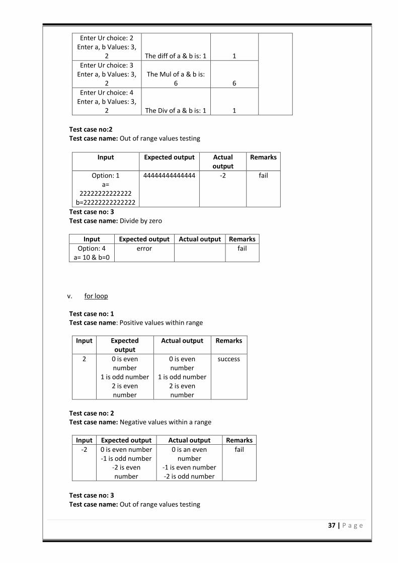
37 | P a g e
Enter Ur choice: 2 Enter a, b Values: 3,
2 The diff of a & b is: 1 1
Enter Ur choice: 3 Enter a, b Values: 3,
2 The Mul of a & b is:
6 6
Enter Ur choice: 4 Enter a, b Values: 3,
2 The Div of a & b is: 1 1
Test case no:2 Test case name: Out of range values testing
Input Expected output Actual
output Remarks
Option: 1 a=
22222222222222 b=22222222222222
44444444444444 -2 fail
Test case no: 3 Test case name: Divide by zero
Input Expected output Actual output Remarks
Option: 4 a= 10 & b=0
error fail
v. for loop Test case no: 1 Test case name: Positive values within range
Input Expected output
Actual output Remarks
2 0 is even number
1 is odd number 2 is even number
0 is even number
1 is odd number 2 is even number
success
Test case no: 2 Test case name: Negative values within a range
Input Expected output Actual output Remarks
-2 0 is even number -1 is odd number
-2 is even number
0 is an even number
-1 is even number -2 is odd number
fail
Test case no: 3 Test case name: Out of range values testing
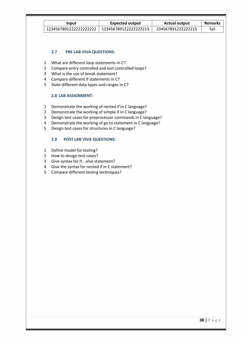
38 | P a g e
Input Expected output Actual output Remarks
1234567891222222222222 123456789122222222213 234567891222222215 fail
2.7 PRE LAB VIVA QUESTIONS:
1 What are different loop statements in C? 2 Compare entry controlled and exit controlled loops? 3 What is the use of break statement? 4 Compare different if statements in C? 5 State different data types and ranges in C?
2.8 LAB ASSIGNMENT:
1 Demonstrate the working of nested if in C language? 2 Demonstrate the working of simple if in C language? 3 Design test cases for preprocessor commands in C language? 4 Demonstrate the working of go to statement in C language? 5 Design test cases for structures in C language?
2.9 POST LAB VIVA QUESTIONS:
1 Define model for testing? 2 How to design test cases? 3 Give syntax for if …else statement? 4 Give the syntax for nested if in C statement? 5 Compare different testing techniques?

39 | P a g e
EXPERIMENT – 2(B)
2.1 OBJECTIVE:
Write a program in ’C’ language to demonstrate the working of palindrome using do…while. 2.2 RESOURCES:
1. Server System configuration: 128 MB of RAM , 500 MB of free disk space, Win NT server, Win
2K server, IIS 5.0, MS Access/Oracle 7.x,8.x,9/MS SQL. 2. Server Client System configuration: 64 MB of RAM , 10 MB of free disk space, Win
95/98/NT/2K/XP, IE 5.
2.3 PROGRAM LOGIC:
1. do …while
declare n, reverse=0, rem,temp. print “Enter an integer”. Read n value. Assign temp to n. while( temp not equal to zero) do rem=temp%10. reverse=reverse*10+rem. temp/=10.
If reverse equal to n Print n is a palindrome. else print n is not a palindrome.
2.4 PROCEDURE:
a. Create : Open editor vi x.c write a program after that press ESC and: wq for save and Quit. b. Compile: gcc x.c. c. Execute: . / a.out.
2.5 SOURCE CODE:
#include <stdio.h> int main() int n, reverse=0, rem,temp;
printf("Enter an integer: "); scanf("%d", &n);
40 | P a g e
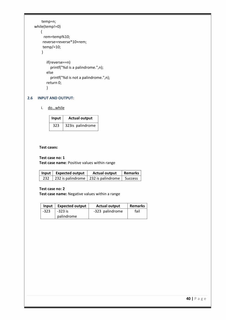
temp=n; while(temp!=0)
rem=temp%10; reverse=reverse*10+rem; temp/=10;
if(reverse==n) printf("%d is a palindrome.",n); else printf("%d is not a palindrome.",n); return 0;
2.6 INPUT AND OUTPUT:
i. do…while
Test cases:
Test case no: 1 Test case name: Positive values within range
Input Expected output Actual output Remarks
232 232 is palindrome 232 is palindrome Success
Test case no: 2 Test case name: Negative values within a range
Input
Actual output
323 323is palindrome
Input Expected output Actual output Remarks
-323 -323 is palindrome
-323 palindrome fail
41 | P a g e
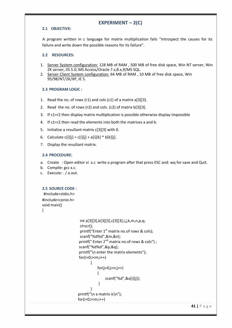
EXPERIMENT – 2(C) 2.1 OBJECTIVE:
A program written in c language for matrix multiplication fails “Introspect the causes for its
failure and write down the possible reasons for its failure”.
2.2 RESOURCES:
1. Server System configuration: 128 MB of RAM , 500 MB of free disk space, Win NT server, Win 2K server, IIS 5.0, MS Access/Oracle 7.x,8.x,9/MS SQL.
2. Server Client System configuration: 64 MB of RAM , 10 MB of free disk space, Win 95/98/NT/2K/XP, IE 5.
2.3 PROGRAM LOGIC :
1. Read the no. of rows (r1) and cols (c1) of a matrix a[3][3]. 2. Read the no. of rows (r2) and cols. (c2) of matrix b[3][3]. 3. If c1=r2 then display matrix multiplication is possible otherwise display impossible 4. If c1=r2 then read the elements into both the matrices a and b. 5. Initialize a resultant matrix c[3][3] with 0. 6. Calculate c[i][j] = c[i][j] + a[i][k] * b[k][j]. 7. Display the resultant matrix.
2.4 PROCEDURE:
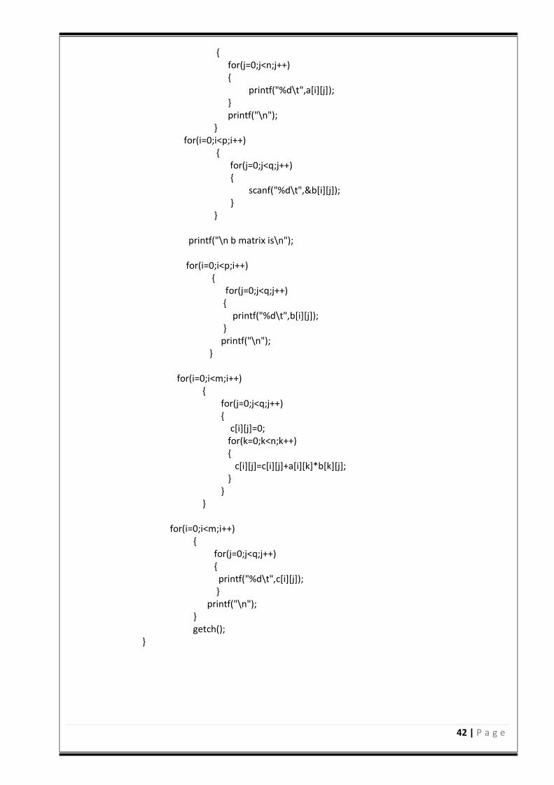
a. Create : Open editor vi x.c write a program after that press ESC and: wq for save and Quit. b. Compile: gcc x.c. c. Execute: . / a.out. 2.5 SOURCE CODE :
#include<stdio.h>
#include<conio.h> void main() int a[3][3],b[3][3],c[3][3],i,j,k,m,n,p,q; clrscr(); printf(“Enter 1st matrix no.of rows & cols); scanf(“%d%d”,&m,&n); printf(“ Enter 2nd matrix no.of rows & cols”) ; scanf(“%d%d”,&p,&q); printf("\n enter the matrix elements"); for(i=0;i<m;i++) for(j=0;j<n;j++) scanf("%d",&a[i][j]); printf("\n a matrix is\n"); for(i=0;i<m;i++)
42 | P a g e
for(j=0;j<n;j++) printf("%d\t",a[i][j]); printf("\n"); for(i=0;i<p;i++) for(j=0;j<q;j++) scanf("%d\t",&b[i][j]); printf("\n b matrix is\n"); for(i=0;i<p;i++) for(j=0;j<q;j++) printf("%d\t",b[i][j]); printf("\n"); for(i=0;i<m;i++) for(j=0;j<q;j++) c[i][j]=0; for(k=0;k<n;k++) c[i][j]=c[i][j]+a[i][k]*b[k][j]; for(i=0;i<m;i++) for(j=0;j<q;j++) printf("%d\t",c[i][j]); printf("\n"); getch();
43 | P a g e
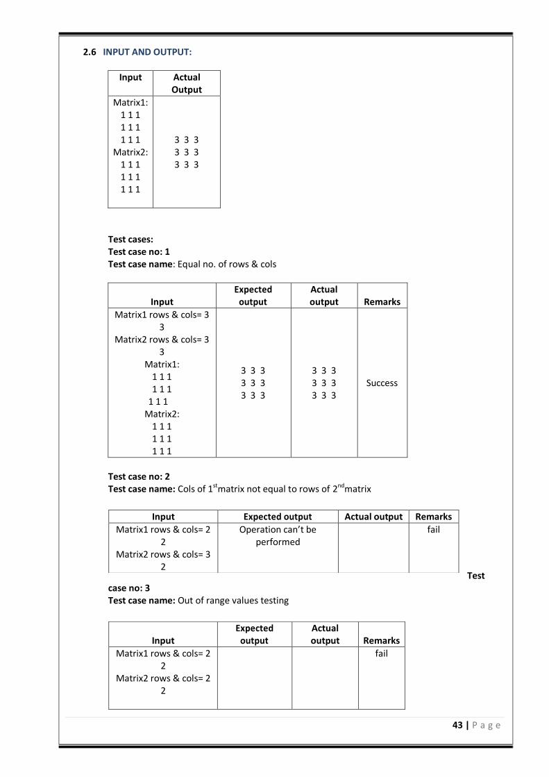
2.6 INPUT AND OUTPUT:
Input Actual Output
Matrix1: 1 1 1 1 1 1 1 1 1
Matrix2: 1 1 1 1 1 1 1 1 1
3 3 3 3 3 3 3 3 3
Test cases: Test case no: 1 Test case name: Equal no. of rows & cols
Input Expected
output Actual output Remarks
Matrix1 rows & cols= 3 3
Matrix2 rows & cols= 3 3
Matrix1: 1 1 1 1 1 1
1 1 1 Matrix2:
1 1 1 1 1 1 1 1 1
3 3 3 3 3 3 3 3 3
3 3 3 3 3 3 3 3 3
Success
Test case no: 2 Test case name: Cols of 1stmatrix not equal to rows of 2ndmatrix
Test case no: 3 Test case name: Out of range values testing
Input Expected output Actual output Remarks
Matrix1 rows & cols= 2 2
Matrix2 rows & cols= 3 2
Operation can’t be performed
fail
Input Expected
output Actual output Remarks
Matrix1 rows & cols= 2 2
Matrix2 rows & cols= 2 2
fail
44 | P a g e
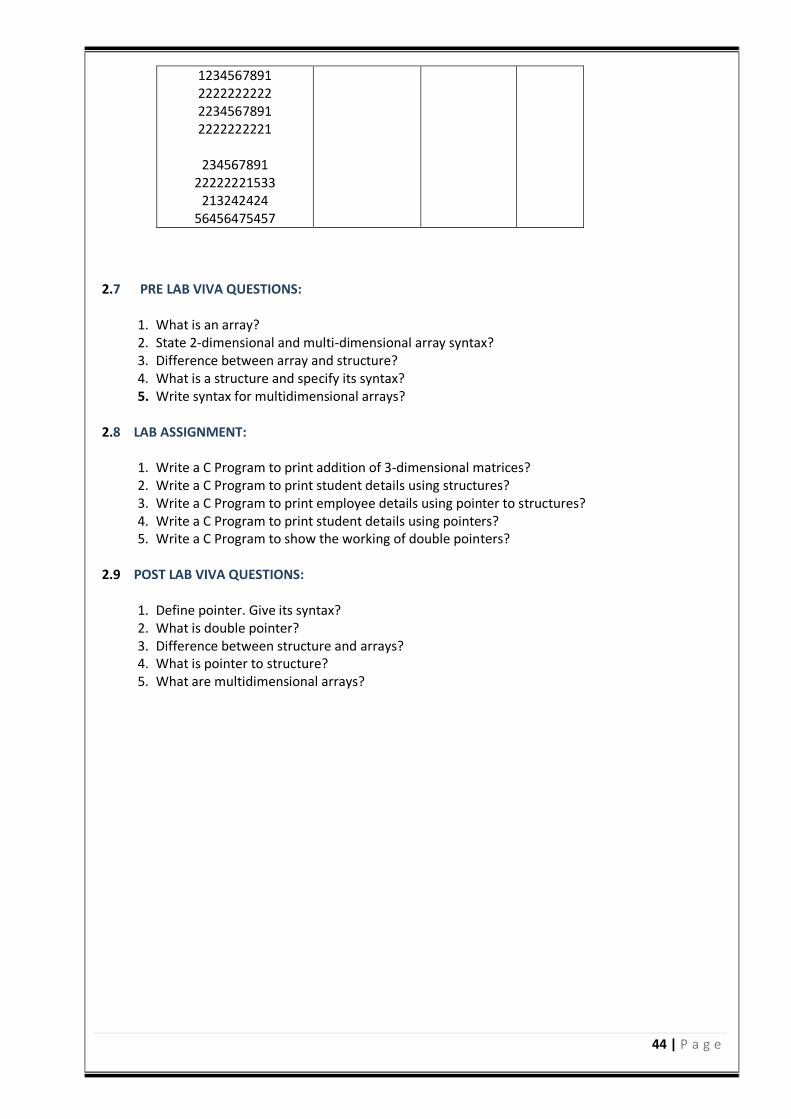
2.7 PRE LAB VIVA QUESTIONS:
1. What is an array? 2. State 2-dimensional and multi-dimensional array syntax? 3. Difference between array and structure? 4. What is a structure and specify its syntax? 5. Write syntax for multidimensional arrays?
2.8 LAB ASSIGNMENT:
1. Write a C Program to print addition of 3-dimensional matrices? 2. Write a C Program to print student details using structures? 3. Write a C Program to print employee details using pointer to structures? 4. Write a C Program to print student details using pointers? 5. Write a C Program to show the working of double pointers?
2.9 POST LAB VIVA QUESTIONS:
1. Define pointer. Give its syntax? 2. What is double pointer? 3. Difference between structure and arrays? 4. What is pointer to structure? 5. What are multidimensional arrays?
1234567891 2222222222 2234567891 2222222221
234567891
22222221533 213242424
56456475457
45 | P a g e
EXPERIMENT – 2(D)
2.1 OBJECTIVE: Study of Any Testing Tool( Win Runner) 2.2 RESOURCES:
1. Server System configuration: 128 MB of RAM , 500 MB of free disk space, Win NT server, Win 2K server, IIS 5.0, MS Access/Oracle 7.x,8.x,9/MS SQL.
2. Server Client System configuration: 64 MB of RAM , 10 MB of free disk space, Win 95/98/NT/2K/XP, IE 5.
2.3 STUDY OF WIN RUNNER TESTING TOOL:
Win Runner is a program that is responsible for the automated testing of software. Win Runner is a Mercury Interactive enterprise functional testing tool for Microsoft windows applications. Importance of Automated Testing: Reduced testing time Consistent test procedures – ensure process repeatability and resource independence. Eliminates errors of manual testing. Reduces QA cost – Upfront cost of automated testing is easily recovered over the life-time of the product .Improved testing productivity – test suites can be run earlier and more often Proof of adequate testing .For doing Tedious work – test team members can focus on quality areas. Win Runner Uses: 1. With Win Runner sophisticated automated tests can be created and run on an application. A
series of wizards will be provided to the user, and these wizards can create tests in an automated manner.
2. Another impressive aspect of Win Runner is the ability to record various interactions, and transform them into scripts. Win Runner is designed for testing graphical user interfaces. When the user make an interaction with the GUI, this interaction can be recorded. Re-cording the interactions allows determining various bugs that need to be fixed. When the test is completed, Win Runner will provide with detailed information regarding the results. It will show the errors that were found, and it will also give important information about them. The good news about these tests is that they can be reused many times.
3. Win Runner will test the computer program in a way that is very similar to normal user interactions. This is important, because it ensures a high level of accuracy and realism. Even if an engineer is not physically present, the Recover manager will troubleshoot any problems that may occur, and this will allow the tests to be completed without errors.
4. The Recover Manager is a powerful tool that can assist users with various scenarios. This is important, especially when important data needs to be recovered.
5. The goal of Win Runner is to make sure business processes are properly carried out. Win Runner uses TSL, or Test Script Language.
Win Runner Testing Modes Context Sensitive Context Sensitive mode records your actions on the application being tested in terms of the GUI objects you select (such as windows, lists, and buttons), while ignoring the physical location of the object on the screen. Every time you perform an operation on the application being tested, a TSL
46 | P a g e
statement describing the object selected and the action performed is generated in the test script. As you record, Win Runner writes a unique description of each selected object to a GUI map. The GUI map consists of files maintained separately from your test scripts. If the user interface of your application changes, you have to update only the GUI map, instead of hundreds of tests. This allows you to easily reuse your Context Sensitive test scripts on future versions of your application. To run a test, you simply play back the test script. Win Runner emulates a user by moving the mouse pointer over your application, selecting objects, and entering keyboard input. Win Runner reads the object descriptions in the GUI map and then searches in the application being tested for objects matching these descriptions. It can locate objects in a window even if their placement has changed. Analog Analog mode records mouse clicks, keyboard input, and the exact x and y coordinates traveled by the mouse. When the test is run, Win Runner retraces the mouse tracks. Use Analog mode when exact mouse coordinates are important to your test, such as when testing a drawing application. The Win Runner Testing Process Testing with Win Runner involves six main stages: 1. Create the GUI Map The first stage is to create the GUI map so Win Runner can recognize the GUI objects in the application being tested. Use the Rapid Test Script wizard to review the user interface of your application and systematically add descriptions of every GUI object to the GUI map. Alternatively, you can add descriptions of individual objects to the GUI map by clicking objects while recording a test. 2. Create Tests Next is creation of test scripts by recording, programming, or a combination of both. While recording tests, insert checkpoints where we want to check the response of the application being tested. We can insert checkpoints that check GUI objects, bitmaps, and databases. During this process, Win Runner captures data and saves it as expected results the expected response of the application being tested. 3. Debug Tests Run tests in Debug mode to make sure they run smoothly. One can set breakpoints, monitor variables, and control how tests are run to identify and isolate defects. Test results are saved in the debug folder, which can be discarded once debugging is finished. When Win Runner runs a test, it checks each script line for basic syntax errors, like incorrect syntax or missing elements in If, While, Switch, and For statements. We can use the Syntax Check options (Tools >Syntax Check) to check for these types of syntax errors before running your test. 4. Run Tests Tests can be run in Verify mode to test the application. Each time Win Runner encounters a checkpoint in the test script, it compares the current data of the application being tested to the expected data captured earlier. If any mismatches are found, Win Runner captures them as actual results. 5. View Results

47 | P a g e
Following each test run, Win Runner displays the results in a report. The report details all the major events that occurred during the run, such as checkpoints, error messages, system messages, or user messages. If mismatches are detected at checkpoints during the test run, we can view the expected results and the actual results from the Test Results window. In cases of bitmap mismatches, one can also view a bitmap that displays only the difference between the expected and actual results. We can view results in the standard Win Runner report view or in the Unified report view. The Win Runner report view displays the test results in a Windows style viewer. The Unified report view displays the results in an HTML style viewer (identical to the style used for Quick Test Professional test results). 6. Report Defects If a test run fails due to a defect in the application being tested, one can report information about the defect directly from the Test Results window .This information is sent via e-mail to the quality assurance manager, who tracks the defect until it is fixed. Using Win runner Window Before you begin creating tests, you should familiarize yourself with the Win Runner main window. To start Win Runner: Choose Programs>Win Runner>Win Runner on the Start menu. The first time you start Win Runner, the Welcome to Win Runner window and the What‘s New in Win Runner help open. From the Welcome window you can create a new test, open an existing test, or view an overview of Win Runner in your default browser. If you do not want this window to appear the next time you start Win Runner, clear the Show on Startup check box. To show the Welcome to Win Runner window upon startup from within Win Runner, choose Settings > General Options, click the Environment tab, and select the Show Welcome screen check box. The Main Win Runner Window The main Win Runner window contains the following key elements: 1. Win Runner title bar 2. Menu bar, with drop-down menus of Win Runner commands 3. Standard toolbar, with buttons of commands commonly used when running a test 4. User toolbar, with commands commonly used while creating a test 5. Status bar, with information on the current command, the line number of the insertion point
and the name of the current results folder 6. The Standard toolbar provides easy access to frequently performed tasks, such as opening,
executing, and saving tests, and viewing test results. Standard Toolbar The User toolbar displays the tools you frequently use to create test scripts. By default, the User toolbar is hidden. To display the User toolbar, choose Window>User Toolbar. When you create tests, you can minimize the Win Runner window and work exclusively from the toolbar. The User toolbar is customizable. You choose to add or remove buttons using the Settings > Customize User Toolbar menu option. When you reopen Win Runner, the User toolbar appears as it was when you
48 | P a g e
last closed it. The commands on the Standard toolbar and the User toolbar are described in detail in subsequent lessons. Note that you can also execute many commands using soft keys. Sof keys are keyboard shortcuts for carrying out menu commands. You can configure the softkey combinations for your keyboard using the Softkey Configuration utility in your Win Runner program group. For more information, see the Win Runner at a Glance chapter in your Win Runner User’s Guide. Now that you are familiar with the main Win Runner window, take a few minutes to explore these window components before proceeding to the next lesson. The Test Window You create and run Win Runner tests in the test window. It contains the following key elements: 1. Test window title bar, with the name of the open test 2. Test script, with statements generated by recording and/or programming in TSL, Mercury
Interactive‘s Test Script Language. 3. Execution arrow, which indicates the line of the test script being executed during a test run, or
the line that will next run if you select the Run from arrow option 4. Insertion point, which indicates where you can insert or edit text. Sample -1 Create a script by recording in Context Sensitive mode that tests the process of opening an order in the Flight Reservation application. You will create the script 1. Start Win Runner.
If Win Runner is not already open, choose Programs > Win Runner > Win Runner on the Start menu.
2. Open a new test.
If the Welcome window is open, click the New Test button. Otherwise, choose File > New. A new test window opens in Win Runner.
3. Start the Flight Reservation application and log in.
Choose Programs > Win Runner > Sample Applications > Flight 1A on the Start menu. In the Login window, type your name and the password mercury, and click OK. The name you type must be at least four characters long. Position the Flight Reservation application and Win Runner so that they are both clearly visible on your desktop.
4. Start recording in Context Sensitive mode.
In Win Runner, choose Create > Record—Context Sensitive or click the Record button on the toolbar. From this point on, Win Runner records all mouse clicks and keyboard input. Note that the text, “Rec” appears in blue above the recording button. This indicates that you are recording in Context Sensitive mode. The status bar also informs you of your current recording mode.
5. Open order #3.
In the Flight Reservation application, choose File > Open Order. In the Open Order dialog box, select the Order No. check box. Type 3 in the adjacent box, and click OK. Watch how Win Runner generates a test script in the test window as you work.
6. Stop recording.
In Win Runner, choose Create > Stop Recording or click the Stop button on the toolbar. 7. Save the test.
49 | P a g e
Choose File > Save or click the Save button on the toolbar. Save the test as lesson3 in a convenient location on your hard drive. Click Save to close the Save Test dialog box. Note that Win Runner saves the lesson3 test in the file system as a folder, and not as an individual file. This folder contains the test script and the results that are generated when you run the test.
Output: Win Runner Test Results window is open and displays the test results. Conclusion: Recording in Context Sensitive mode is cleared and test results are also seen. Sample -2 Aim: Purpose of this exercise is to Study Synchronizing test Synchronizing test When you run tests, your application may not always respond to input with the same speed. For example, it might take a few seconds: 1. To retrieve information from a database 2. For a window to pop up 3. For a progress bar to reach 100% 4. For a status message to appear Win Runner waits a set time interval for an application to respond to input. The default wait interval is up to 10 seconds. If the application responds slowly during a test run, Win Runner’s default wait time may not be sufficient, and the test run may unexpectedly fail. If you discover a synchronization problem between the test and your application, you can either: • Increase the default time that Win Runner waits. To do so, you change the value of the Timeout for Checkpoints and CS Statements option in the Run tab of the General Options dialog box(Settings > General Options). This method affects all your tests and slows down many other Context Sensitive operations. Insert a synchronization point into the test script at the exact point where the problem occurs. A synchronization point tells Win Runner to pause the test run in order to wait for a specified response in the application. This is the recommended method for synchronizing a test with your application. In the following exercises you will: 1. Create a test that opens a new order in the Flight Reservation application and inserts the order
into the database 2. Change the synchronization settings 3. Identify a synchronization problem 4. Synchronize the test 5. Run the synchronized test Input: Creating a Test
In this first exercise you will create a test that opens a new order in the Flight Reservation application and inserts the order into a database. 1. Start Win Runner and open a new test.
If Win Runner is not already open, choose Programs > Win Runner > Win Runner on the Start menu. If the Welcome window is open, click the New Test button. Otherwise, choose File > New. A new test window opens.
2. Start the Flight Reservation application and log in.
50 | P a g e
Choose Programs > Win Runner > Sample Applications > Flight 1A on the Start menu. In the Login window, type your name and the password mercury, and click OK. Reposition the Flight Reservation application and Win Runner so that they are both clearly visible on your desktop.
3. Start recording in Context Sensitive mode.
Choose Create > Record Context Sensitive or click the Record button on the tool bar.Win Runner will start recording the test.
4. Create a new order.
Choose File > New Order in the Flight Reservation application. 5. Fill in flight and passenger information.
6. Insert the order into the database.
Click the Insert Order button. When the insertion is complete, the “Insert Done” message appears in the status bar.
7. Delete the order.
Click the Delete Order button and click Yes in the message window to confirm the deletion. 8. Stop recording.
Choose Create > Stop Recording or click the Stop button. 9. Save the test.
Choose File > Save. Save the test as lesson4 in a convenient location on your hard drive. Click Save to close the Save Test dialog box.
Output: Win Runner Test Results window is open and displays the test results. Conclusion: Importance of Synchronizing test is cleared and test results are also seen. Sample -3 Aim: When working with an application, you can determine whether it is functioning properly according to the behavior of its GUI objects. Checking GUI Objects Input: Adding GUI Checkpoints to a Test Script
In this exercise you will check that objects in the Flight Reservation Open Order dialog box function properly when you open an existing order.
d. Start Win Runner and open a new test.
If Win Runner is not already open, choose Programs > Win Runner > Win Runner on the Start menu. If the Welcome window is open, click the New Test button. Otherwise, choose File > New. A new test window opens.
2 .Start the Flight Reservation application and log in.
Choose Programs > Win Runner > Sample Applications > Flight 1A on the Start menu. In the Login window, type your name and the password mercury, and click OK. Reposition the Flight Reservation application and Win Runner so that they are both clearly visible on your desktop.
51 | P a g e
3 Start recording in Context Sensitive mode.
Choose Create > Record Context Sensitive or click the Record button on the toolbar. 4 Open the Open Order dialog box.
Choose File > Open Order in the Flight Reservation application. 6. Create a GUI checkpoint for the Order No. check box.
Choose Create > GUI Checkpoint > For Object/Window, or click the GUI Checkpoint for Object/Window button on the User toolbar .Use the pointer to double click the Order No. check box. The Check GUI dialog box opens and displays the available checks. Note that this dialog box does not open if you only single clicked the Order No. check box. Accept the default check, “State.” This check captures the current state (off) of the check box and stores it as expected results. Click OK in the Check GUI dialog box to insert the checkpoint into the test script. The checkpoint appears as an obj check gui statement.
7. Enter “4” as the Order No. Select the Order No. check box and type in 4 in the Order No. text box. 8. Create another GUI checkpoint for the Order No. check box.
Choose Create > GUI Checkpoint > For Object/Window or click the GUI Checkpoint for Object/Window button on the User toolbar. Use the pointer to single click the Order No. check box. Win Runner immediately inserts a checkpoint into the test script (an obj_check_gui statement) that checks the default check “State.” (Use this shortcut when you want to use only the default check for an object.) This check captures the current state (on) of the check box and stores it as expected results.
9. Create a GUI checkpoint for the Customer Name check box.
Choose Create > GUI Checkpoint > For Object/Window or click the GUI Checkpoint for Object/Window button on the User toolbar. Use the pointer to double click the Customer Name check box. The Check GUI dialog box opens and displays the available checks. Accept the default check “State” and select “Enabled” as an additional check. The State check captures the current state (off) of the check box; the Enabled check captures the current condition (off) of the check box. Click OK in the Check GUI dialog box to insert the checkpoint into the test script. The checkpoint appears as an obj_check_gui statement.
10. Click OK in the Open Order dialog box to open the order. 11. Stop recording. Choose Create > Stop Recording or click the Stop button. 12. Save the test.
Choose File > Save or click the Save button. Save the test as lesson5 in a convenient location on your hard drive. Click Save to close the Save Test dialog box.
13. If you are working in the Global GUI Map File mode, save the new objects to the GUI map.
Choose Tools > GUI Map Editor. Choose View > GUI Files. Choose File > Save. Click Yes or OK to add the new object or new window to your GUI map. Choose File > Exit to close the GUI Map Editor.
In Running the Test you will now run the lesson5 test in order to verify that the test runs smoothly. 1. Make sure that the Flight Reservation application is open on your desktop.
52 | P a g e
2. In Win Runner, check that Verify mode is selected in the Standard toolbar. 3. Choose Run from Top.
Choose Run > Run from Top, or click the Run from Top button. The Run Test dialog box opens. Accept the default test run name “res1.” Make sure that the Display test results at end of run check box is selected.
4. Run the test. Click OK in the Run Test dialog box. 5. Review the results.
When the test run is completed, the test results appear in the Win Runner Test Results window. In the test log section all “end GUI checkpoint” events should appear in green (indicating success).Double click an end GUI checkpoint event to view detailed results of that GUI checkpoint. The GUI Checkpoint Results dialog box opens. Select Customer Name to display the dialog box as follows:
Output: Win Runner Test Results window is open and displays the test results. Conclusion: Explains how to check the behavior of GUI objects and shows you how to create a test that checks GUI objects. Sample -4 Aim: Purpose of these exercises to study a bitmap checkpoint compares captured bitmap images pixel by pixel. Input: Checking Bitmap Objects Adding Bitmap Checkpoints to a Test Script In this exercise you will test the Agent Signature box in the Fax Order dialog boxYou will use a bitmap checkpoint to check that you can sign your name in the box Then you will use another bitmap checkpoint to check that the box clears when you click the Clear Signature button. 1. Start Win Runner and open a new test.
If Win Runner is not already open, choose Programs > WinRunner > WinRunner on the Start menu. If the Welcome window is open, click the New Test button. Otherwise, choose File > New. A new test window opens.
2. Start the Flight Reservation application and log in.
Choose Programs > Win Runner > Sample Applications > Flight 1A on the Start menu. In the Login window, type your name and the password mercury, and click OK. Reposition the Flight Reservation application and Win Runner so that they are both clearly visible on your desktop.
3. Start recording in Context Sensitive mode.
Choose Create > Record—Context Sensitive or click the Record button on the toolbar.
4. Open order #6. In the Flight Reservation application, choose File > Open Order. In the Open Order dialog box, select the Order No. check box and type “6” in the adjacent box. Click OK to open the order.
5. Open the Fax Order dialog box.
Choose File > Fax Order.
53 | P a g e
6. Enter a 10digit fax number in the Fax Number box. You do not need to type in parentheses or dashes.
7. Move the Fax Order dialog box.
Position the dialog box so that it least obscures the Flight Reservation window. 8. Switch to Analog mode.
Press F2 on your keyboard or click the Record button to switch to Analog mode.
9. Sign your name in the Agent Signature box. 10. Switch back to Context Sensitive mode.
Press F2 on your keyboard or click the Record button to switch back to Context Sensitive mode.
11. Insert a bitmap checkpoint that checks your signature. Choose Create > Bitmap Checkpoint > For Object/Window or click the Bitmap Checkpoint for Object/Window button on the User toolbar.Use the pointer to click the Agent Signature box. Win Runner captures the bitmap and inserts an obj_check_bitmap statement into the test script.
12. Click the Clear Signature button.
The signature is cleared from the Agent Signature box. 13. Insert another bitmap checkpoint that checks the Agent Signature box.
Choose Create > Bitmap Checkpoint > For Object/Window or click the Bitmap Checkpoint for Object/Window button on the User toolbar.Use the pointer to click the Agent Signature box. Win Runner captures a bitmap and inserts an obj_check_bitmap statement into the test script.
14. Click the Cancel button on the Fax Order dialog box. 15. Stop recording.
Choose Create > Stop Recording or click the Stop button.
16. Save the test. Choose File > Save or click the Save button. Save the test as lesson6 in a convenient location on your hard drive. Click Save to close the Save Test dialog box.
17. If you are working in the Global GUI Map File mode, save the new objects to the GUI map.
Choose Tools > GUI Map Editor. Choose View > GUI Files. Choose File >Save. Click Yes or OK to add the new object or new window to your GUI map. Choose File > Exit to close the GUI Map Editor.
Output: Viewing Expected Results You can now view the expected results of the test. 1. Open the Win Runner Test Results window.
Choose Tools > Test Results or click the Test Results button. The Test Results window opens. 2. View the captured bitmaps.
54 | P a g e
In the test log section, double click the first “capture bitmap” event, or select it and click the Display button.Next, doubleclick the second “capture bitmap” event, or select it and click the Display button.
3. Close the Test Results window.
Close the bitmaps and choose File > Exit to close the Test Results window. Conclusion: Bitmap checkpoint compares captured bitmap images captured bitmap images pixel by pixel. Checking Bitmaps Sample -5 Aim: Purpose of these exercises to study shows you how to use the Data Driver Wizard to create a data driven test Input: Creating data driven test Converting Your Test to a Data Driven Test Start by opening the test you already created and using the Data Driver Wizard to parameterize the test. 1. Create a new test from the lesson7 test.
If WinRunner is not already open, choose Programs > WinRunner > WinRunner on the Start menu. If the Welcome window is open, click the Open Test button. Otherwise, choose File > Open and select the test you created previously. The test opens. Choose File > Save As and save the test as lesson8 in a convenient location on your hard drive.
2. Run the Data Driver Wizard. Choose Tools > Data Driver Wizard. The Data Driver Wizard welcome window opens. Click Next to begin the parameterization process.
3. Create a data table for the test. In the Use a new or existing Excel table box, type “lesson8”. The Data Driver Wizard creates an Excel table with this name and saves it the test folder.
4. Assign a table variable name.
Accept the default table variable name, “table”. At the beginning of a data driven test, the Excel data table you wish to use is assigned as the value of the table variable. Throughout the script, only the table variable name is used. This makes it easy for you to assign a different data table to the script at a later time without making changes throughout the script.
5. Select global parameterization options.
Select Add statements to create a data driven test. This adds TSL statements to the test that define the table variable name, open and close the data table, and run the appropriate script selection in a loop for each row in the data table. Select parameterize the test and choose the Line by line option. When you select Parameterize the test, you instruct Win Runner to find fixed values in recorded statements and selected checkpoints and to replace them with parameters. The Line by line option instructs the wizard to open a screen for each line of the selected test that can be parameterized so that you can choose whether or not to parameterize that line. Click Next.
6. Select the data to parameterize.
55 | P a g e
The first line byline screen opens. It refers to the Order Number radio button. Adding Data to the Data Table Now that you have parameterized your test, you are ready to add the data the parameterized test will use. 1. Open the data table.
Choose Tools > Data Table. The lesson8.xls table opens. Note that there is one column named “Order_Num”, and that the first row in the column contains value “4”.
2. Add data to the table. In rows 2, 3, 4, and 5 of the Order_Num column, enter the values, “1”, “6”, and “10” respectively.
3. Save and close the table.
Click an empty cell and choose File > Save from the data table menu. Then choose File > Close to close the table.
4. Save the test. Choose File > Save or click the Save button. Click Save to close the Save Test dialog box.
Output: Review the results. When the test run is completed, the test results appear in the Win Runner Test Results window. Note that the tl_step event is listed five times and that the details for each iteration include the actual number of tickets, price and total cost that was checked. Conclusion: Use Data Driver Wizard to create a data driven test. Sample-6 Aim: Explains how the GUI map enables you to continue using your existing test scripts after the user interface changes in your application. Input: Maintaining test script Editing Object Descriptions in the GUI Map Suppose that in a new version of the Flight Reservation application, the Insert Order button is changed to an Insert button. In order to continue running tests that use the Insert Order button, you must edit the label in the button’s physical description in the GUI map. You can change the physical description using regular expressions. 1. Start Win Runner and open a new test.
If Win Runner is not already open, choose Programs > Win Runner > Win Runner on the Start menu. If the Welcome window is open, click the New Test button. Otherwise, choose File > New. A new test window opens. If you are working in the GUI Map File per Test mode, open the lesson4 test.
2. Open the GUI Map Editor. Choose Tools > GUI Map Editor. The GUI Map Editor opens. Make sure that View > GUI Map is selected. The Windows/Object list displays the current contents of the GUI Map. (If you are working in the GUI Map File per Test Mode, the GUI Map Editor will contain fewer objects than as shown below).The GUI Map Editor displays the object names in a tree. Preceding each
56 | P a g e
name is an icon representing the object’s type. The objects are grouped according to the window in which they are located. You can double click a window icon to collapse or expand the view of its objects.
3. Find the Insert Order button in the tree.
In the GUI Map Editor, choose View > Collapse Objects Tree to view only the window titles.(If you are working in the GUI Map File per Test Mode, the GUI Map Editor will contain fewer objects than as shown below. Double click the Flight Reservation window to view its objects. If necessary, scroll down the alphabetical object list until you locate the Insert Order button.
4. View the Insert Order button’s physical description.
Click the Insert Order button in the tree. (If you are working in the GUI Map File per Test Mode, the GUI Map Editor will contain fewer objects than as shown below.)The physical description object is displayed in the bottom pane of the GUI Map Editor.
5. Modify the Insert Order button’s physical description.
Click the Modify button or double click the Insert Order button. The Modify dialog box opens and displays the button’s logical name and physical description. In the Physical Description box, change the label property from Insert Order to Insert. Click OK to apply the change and close the dialog box.
6. Close the GUI Map Editor.
In the GUI Map Editor, choose File > Save to save your changes and then choose File > Exit. If you are working in the GUI Map File per Test Mode, choose File > Exit in the GUI Map Editor and then File > Save in Win Runner. The next time you run a test that contains the logical name “Insert Order”, WinRunner will locate the Insert button in the Flight Reservation window. If you are working in the GUI Map File per Test Mode, go back and perform steps1 through 6 for the lesson9 test. In practice, all maps containing the modified object/window must be changed.
Maintaining Your Test Scripts Adding GUI Objects to the GUI Map Note: If you are working in the GUI Map File per Test mode, skip this exercise,since new objects are saved in your test’s GUI map automatically when you save your test.If your application contains new objects, you can add them to the GUI map without running the RapidTest Script wizard again. You simply use the Learn button in the GUI Map Editor to learn descriptions of the objects. You can learn the description of a single object or all the objects in a window. In this exercise you will add the objects in the Flight Reservation Login window to the GUI map. 1. Open the Flight Reservation Login window.
Choose Programs > Win Runner > Sample Applications > Flight 1A on the Start menu.
2. Open the GUI map. In Win Runner, choose Tools > GUI Map Editor. The GUI Map Editor opens.
3 Learn all the objects in the Login window.
Click the Learn button. Use the pointer to click the title bar of the Login window. A message prompts you to learn all the objects in the window. Click Yes. Watch as Win Runner learns a description of each object in the Login window and adds it to the temporary GUI Map.
4. Save the new objects in the GUI map.
57 | P a g e
Choose Tools > GUI Map Editor. Choose View > GUI Files. Choose File >Save. Click Yes or OK to add the new object or new window to your GUI map. Choose File > Exit to close the GUI Map Editor. 5 Close the Login window. Click Cancel.
Updating the Map with the Run GUI Wizard Note: If you are working in the GUI Map File per Test mode, skip this exercise,since new objects are automatically saved in your test’s GUI map when you save your test.During a test run, if Win Runner cannot locate an object mentioned in the test script, the Run wizard opens. The Run wizard helps you update the GUI map so that your tests can run smoothly. It prompts you to point to the object in our application, determines why it could not find the object, and then offers a solution. In most cases the Run wizard will automatically modify the object description in the GUI map or add a new object description. For example, suppose you run a test that clicks the Insert Order button in the Flight Reservation window: button_press ("Insert Order");If the Insert Order button is changed to an Insert button, the Run wizard opens during a test run and describes the problem.You click the hand button in the wizard and click the Insert button in the Flight Reservation program. The Run wizard then offers a solution: When you click OK, Win Runner automatically modifies the object’s physical description in the GUI map and then resumes the test run.
If you would like to see for yourself how the Run wizard works:
1. Open the GUI map. a. Choose Tools > GUI Map Editor. Choose View > GUI Files.
2. Delete the “Fly From” list object from the GUI Map Editor tree. a. The Fly From object is listed under the Flight Reservation window. Select this object and click the Delete button in the GUI Map Editor.
3. Open Flight Reservation 1A. a. Choose Programs > Win Runner > Sample Applications > Flight 1A on the Start menu. In the Login window, type your name and the password mercury, and click OK. Reposition the Flight Reservation application and Win Runner so that they are both clearly visible on your desktop.
4. In Win Runner, open the lesson4 test and run it. a. Watch what happens when WinRunner reaches the statement list_select_item ("Fly From:", "Los Angeles")
5. Follow the Run wizard instructions. a. The Run wizard asks you to point to the Fly From object and then adds the object description to the GUI map. Win Runner then continues the test run.
6. Find the object description in the GUI map. a. When Win Runner completes the test run, return to the GUI Map Editor and look for the Fly From object description. You can see that the Run wizard has added the object to the tree.
7. Close the GUI Map. a. In the GUI Map Editor, choose File > Exit.
8. Close the Flight Reservation application. a. Choose File > Exit. b. Conclusion: GUI map enables using existing test scripts after the user interface changes in application.
2.4 PRE LAB VIVA QUESTIONS:
1. Define win runner? 2. Explain uses of win runner? 3. What are different modes of win runner?

58 | P a g e
4. Explain win runner testing process? 5. How to test a module using win runner?
2.5 LAB ASSIGNMENT:
1. Create a script in win runner in context sensitive mode? 2. What are the steps for synchronizing test in win runner? 3. Generate test cases for library application using win runner? 4. Generate test cases for online shopping? 5. Generate test cases for bank application?
2.6 POST LAB VIVA QUESTIONS: 1. Define context sensitive mode? 2. What is test script? 3. What is data driver wizard? 4. How to create test in win runner? 5. How to debug test in win runner?
59 | P a g e
EXPERIMENT – 3 (A)
3.1 OBJECTIVE:
Study of any web testing tool (e.g. Selenium)
3.2 RESOURCES:
1. Server System configuration: 128 MB of RAM , 500 MB of free disk space, Win NT server, Win 2K server, IIS 5.0, MS Access/Oracle 7.x,8.x,9/MS SQL.
2. Server Client System configuration: 64 MB of RAM , 10 MB of free disk space, Win 95/98/NT/2K/XP, IE 5.
3.3 STUDY OF SELENIUM WEB TESTING TOOL:
1. Selenium is a robust set of tools that supports rapid development of test automation for web-based applications. Selenium provides a rich set of testing functions specifically geared to the needs of testing of a web application. These operations are highly flexible, allowing many options for locating UI elements and comparing expected test results against actual application behavior.
2. One of Selenium‘s key features is the support for executing one‘s tests on multiple browser platforms.
3. Selenium Components 4. Selenium is composed of three major tools. Each one has a specific role in aiding the
development of web application test automation.
Selenium-RC provides an API (Application Programming Interface) and library for each of its supported languages: HTML, Java, C#, Perl, PHP, Python, and Ruby. This ability to use Selenium-RC with a high level programming language to develop test cases also allows the automated testing to be integrated with a project‘s automated build environment. Selenium-Grid Selenium-Grid allows the Selenium-RC solution to scale for large test suites or test suites that must be run in multiple environments. With Selenium-Grid, multiple instances of Selenium-RC are running on various operating system and browser configurations; Each of these when launching register with a hub. When tests are sent to the hub they are then redirected to an available Selenium-RC, which will launch the browser and run the test. This allows for running tests in parallel, with the entire test suite theoretically taking only as long to run as the longest individual test. 1. Tests developed on Firefox via Selenium-IDE can be executed on any other supported browser via a simple Selenium-RC command line. 2. Selenium-RC server can start any executable, but depending on browser security set-tings there may be technical limitations that would limit certain features. Flexibility and Extensibility
Selenium is highly flexible. There are multiple ways in which one can add functionality to Selenium‘s framework to customize test automation for one‘s specific testing needs. This is, perhaps, Selenium‘s strongest characteristic when compared with proprietary test automation tools and other open source solutions. Selenium-RC support for multiple programming and scripting languages allows the test writer to build any logic they need into their automated testing and to use a preferred programming or scripting language of one‘s choice. Selenium-IDE allows for the addition of user-defined user extensions for creating additional commands customized to the user‘s needs. Also, it is possible to re-configure how the Selenium-IDE generates its Selenium-RC code. This allows users to customize the generated code to fit in with their own test frameworks. Finally, Selenium is an Open Source project where code can be modified and enhancements can be submitted for contribution.
60 | P a g e
Test Suites A test suite is a collection of tests. Often one will run all the tests in a test suite as one continuous batch job. When using Selenium-IDE, test suites also can be defined using a simple HTML file. The syntax again is simple. An HTML table defines a list of tests where each row defines the file system path to each test. An example tells it all. <html> <head> <title>Test Suite Function Tests – Priority 1</title></head> <body> <table> <tr><td><b>Suite Of Tests</b></td></tr> <tr><td><a href=‖./Login.html‖>Login</a></td></tr> <tr><td><a href=‖./SearchValues.html‖>Test Searching for Values</a></td></tr> <tr><td><a href=‖./SaveValues.html‖>Test Save</a></td></tr> </table></body> </html> A file similar to this would allow running the tests all at once, one after another, from the Selenium-IDE. Test suites can also be maintained when using Selenium-RC. This is done via programming and can be done a number of ways. Commonly Junit is used to maintain a test suite if one is using Selenium-RC with Java. Additionally, if C# is the chosen language, Nunit could be employed. If using an interpreted language like Python with Selenium-RC than some simple programming would be involved in setting up a test suite. Since the whole reason for using Sel-RC is to make use of programming logic for your testing this usually isn‘t a problem. Few typical Selenium commands. 1. open – opens a page using a URL. 2. click/clickAndWait – performs a click operation, and optionally waits for a new page to load. 3. verifyTitle/assertTitle – verifies an expected page title. 4. verifyTextPresent – verifies expected text is somewhere on the page. 5. verifyElementPresent – verifies an expected UI element, as defined by its HTML tag, is present
on the page. 6. verifyText – verifies expected text and it‘s corresponding HTML tag are present on the page. 7. verifyTable – verifies a table‘s expected contents. 8. waitForPageToLoad – pauses execution until an expected new page loads. Called automatically
when clickAndWait is used. 9. waitForElementPresent – pauses execution until an expected UI element, as defined by its
HTML tag, is present on the page.
3.4 PRE LAB VIVA QUESTIONS:
1. Explain about selenium tool? 2. Compare win runner and selenium tool? 3. What are the components of selenium tool? 4. What are test suits for selenium tool? 5. Define selenium grid?
61 | P a g e
3.5 LAB ASSIGNMENT:
1. Generate test cases using selenium tool for library application? 2. Generate test cases using selenium tool for online shopping? 3. Generate test cases using selenium tool for bank application? 4. Generate test cases using selenium tool for ATM application? 5. Generate test cases using selenium tool for Google advance search?
3.6 POST LAB VIVA QUESTIONS:
1. Define selenium IDE? 2. What is an html file? 3. Define the use of html file in selenium tool? 4. What are the features of selenium tool? 5. What is selenium RC code?
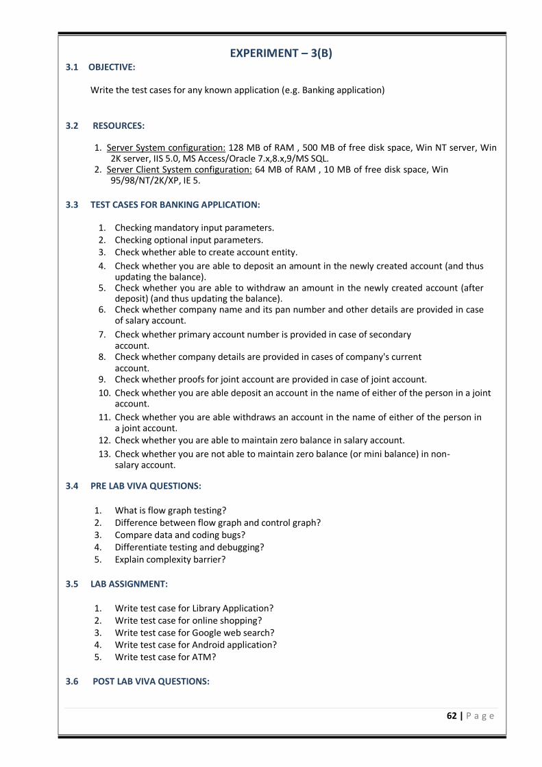
62 | P a g e
EXPERIMENT – 3(B) 3.1 OBJECTIVE:
Write the test cases for any known application (e.g. Banking application)
3.2 RESOURCES:
1. Server System configuration: 128 MB of RAM , 500 MB of free disk space, Win NT server, Win 2K server, IIS 5.0, MS Access/Oracle 7.x,8.x,9/MS SQL.
2. Server Client System configuration: 64 MB of RAM , 10 MB of free disk space, Win 95/98/NT/2K/XP, IE 5.
3.3 TEST CASES FOR BANKING APPLICATION:
1. Checking mandatory input parameters. 2. Checking optional input parameters. 3. Check whether able to create account entity. 4. Check whether you are able to deposit an amount in the newly created account (and thus
updating the balance). 5. Check whether you are able to withdraw an amount in the newly created account (after
deposit) (and thus updating the balance). 6. Check whether company name and its pan number and other details are provided in case
of salary account. 7. Check whether primary account number is provided in case of secondary
account. 8. Check whether company details are provided in cases of company's current
account. 9. Check whether proofs for joint account are provided in case of joint account. 10. Check whether you are able deposit an account in the name of either of the person in a joint
account. 11. Check whether you are able withdraws an account in the name of either of the person in
a joint account. 12. Check whether you are able to maintain zero balance in salary account. 13. Check whether you are not able to maintain zero balance (or mini balance) in non-
salary account.
3.4 PRE LAB VIVA QUESTIONS:
1. What is flow graph testing? 2. Difference between flow graph and control graph? 3. Compare data and coding bugs? 4. Differentiate testing and debugging? 5. Explain complexity barrier?
3.5 LAB ASSIGNMENT:
1. Write test case for Library Application? 2. Write test case for online shopping? 3. Write test case for Google web search? 4. Write test case for Android application? 5. Write test case for ATM?
3.6 POST LAB VIVA QUESTIONS:
63 | P a g e
1. Write about design test cases? 2. What are integration bugs? 3. Define system bugs? 4. What are design specifications? 5. What is path testing?
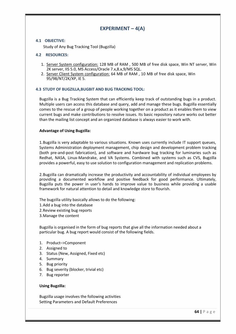
64 | P a g e
EXPERIMENT – 4(A)
4.1 OBJECTIVE:
Study of Any Bug Tracking Tool (Bugzilla)
4.2 RESOURCES:
1. Server System configuration: 128 MB of RAM , 500 MB of free disk space, Win NT server, Win 2K server, IIS 5.0, MS Access/Oracle 7.x,8.x,9/MS SQL.
2. Server Client System configuration: 64 MB of RAM , 10 MB of free disk space, Win 95/98/NT/2K/XP, IE 5.
4.3 STUDY OF BUGZILLA,BUGBIT AND BUG TRACKING TOOL:
Bugzilla is a Bug Tracking System that can efficiently keep track of outstanding bugs in a product. Multiple users can access this database and query, add and manage these bugs. Bugzilla essentially comes to the rescue of a group of people working together on a product as it enables them to view current bugs and make contributions to resolve issues. Its basic repository nature works out better than the mailing list concept and an organized database is always easier to work with.
Advantage of Using Bugzilla:
1. Bugzilla is very adaptable to various situations. Known uses currently include IT support queues, Systems Administration deployment management, chip design and development problem tracking (both pre-and-post fabrication), and software and hardware bug tracking for luminaries such as Redhat, NASA, Linux-Mandrake, and VA Systems. Combined with systems such as CVS, Bugzilla provides a powerful, easy to use solution to configuration management and replication problems.
2. Bugzilla can dramatically increase the productivity and accountability of individual employees by providing a documented workflow and positive feedback for good performance. Ultimately, Bugzilla puts the power in user‘s hands to improve value to business while providing a usable framework for natural attention to detail and knowledge store to flourish.
The bugzilla utility basically allows to do the following: 1. Add a bug into the database 2. Review existing bug reports 3. Manage the content
Bugzilla is organised in the form of bug reports that give all the information needed about a particular bug. A bug report would consist of the following fields.
1. Product–>Component 2. Assigned to 3. Status (New, Assigned, Fixed etc) 4. Summary 5. Bug priority 6. Bug severity (blocker, trivial etc) 7. Bug reporter
Using Bugzilla: Bugzilla usage involves the following activities Setting Parameters and Default Preferences
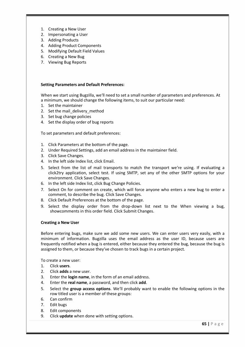
65 | P a g e
1. Creating a New User 2. Impersonating a User 3. Adding Products 4. Adding Product Components 5. Modifying Default Field Values 6. Creating a New Bug 7. Viewing Bug Reports
Setting Parameters and Default Preferences: When we start using Bugzilla, we‘ll need to set a small number of parameters and preferences. At a minimum, we should change the following items, to suit our particular need: 1. Set the maintainer 2. Set the mail_delivery_method 3. Set bug change policies 4. Set the display order of bug reports To set parameters and default preferences:
1. Click Parameters at the bottom of the page. 2. Under Required Settings, add an email address in the maintainer field. 3. Click Save Changes. 4. In the left side Index list, click Email. 5. Select from the list of mail transports to match the transport we‘re using. If evaluating a
click2try application, select test. If using SMTP, set any of the other SMTP options for your environment. Click Save Changes.
6. In the left side Index list, click Bug Change Policies. 7. Select On for comment on create, which will force anyone who enters a new bug to enter a
comment, to describe the bug. Click Save Changes. 8. Click Default Preferences at the bottom of the page. 9. Select the display order from the drop-down list next to the When viewing a bug,
showcomments in this order field. Click Submit Changes.
Creating a New User Before entering bugs, make sure we add some new users. We can enter users very easily, with a minimum of information. Bugzilla uses the email address as the user ID, because users are frequently notified when a bug is entered, either because they entered the bug, because the bug is assigned to them, or because they‘ve chosen to track bugs in a certain project.
To create a new user: 1. Click users. 2. Click adds a new user. 3. Enter the login name, in the form of an email address. 4. Enter the real name, a password, and then click add. 5. Select the group access options. We‘ll probably want to enable the following options in the
row titled user is a member of these groups: 6. Can confirm 7. Edit bugs
8. Edit components 9. Click update when done with setting options.
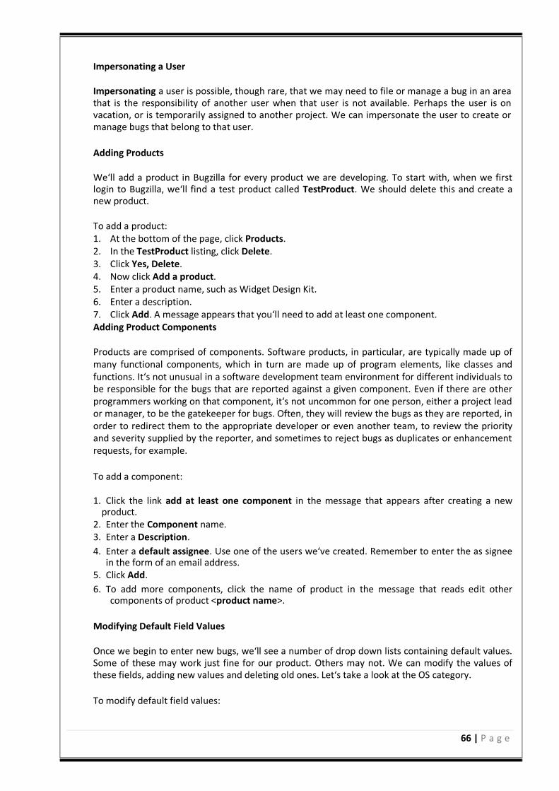
66 | P a g e
Impersonating a User Impersonating a user is possible, though rare, that we may need to file or manage a bug in an area that is the responsibility of another user when that user is not available. Perhaps the user is on vacation, or is temporarily assigned to another project. We can impersonate the user to create or manage bugs that belong to that user.
Adding Products We‘ll add a product in Bugzilla for every product we are developing. To start with, when we first login to Bugzilla, we‘ll find a test product called TestProduct. We should delete this and create a new product. To add a product: 1. At the bottom of the page, click Products. 2. In the TestProduct listing, click Delete. 3. Click Yes, Delete. 4. Now click Add a product. 5. Enter a product name, such as Widget Design Kit. 6. Enter a description. 7. Click Add. A message appears that you‘ll need to add at least one component. Adding Product Components Products are comprised of components. Software products, in particular, are typically made up of many functional components, which in turn are made up of program elements, like classes and functions. It‘s not unusual in a software development team environment for different individuals to be responsible for the bugs that are reported against a given component. Even if there are other programmers working on that component, it‘s not uncommon for one person, either a project lead or manager, to be the gatekeeper for bugs. Often, they will review the bugs as they are reported, in order to redirect them to the appropriate developer or even another team, to review the priority and severity supplied by the reporter, and sometimes to reject bugs as duplicates or enhancement requests, for example.
To add a component: 1. Click the link add at least one component in the message that appears after creating a new
product. 2. Enter the Component name. 3. Enter a Description. 4. Enter a default assignee. Use one of the users we‘ve created. Remember to enter the as signee
in the form of an email address. 5. Click Add. 6. To add more components, click the name of product in the message that reads edit other
components of product <product name>.
Modifying Default Field Values Once we begin to enter new bugs, we‘ll see a number of drop down lists containing default values. Some of these may work just fine for our product. Others may not. We can modify the values of these fields, adding new values and deleting old ones. Let‘s take a look at the OS category.
To modify default field values:
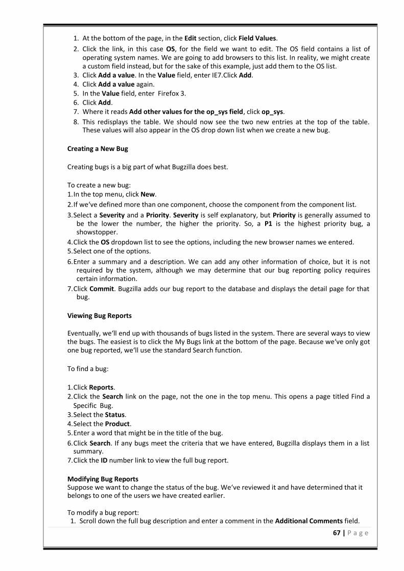
67 | P a g e
1. At the bottom of the page, in the Edit section, click Field Values. 2. Click the link, in this case OS, for the field we want to edit. The OS field contains a list of
operating system names. We are going to add browsers to this list. In reality, we might create a custom field instead, but for the sake of this example, just add them to the OS list.
3. Click Add a value. In the Value field, enter IE7.Click Add. 4. Click Add a value again. 5. In the Value field, enter Firefox 3. 6. Click Add. 7. Where it reads Add other values for the op_sys field, click op_sys. 8. This redisplays the table. We should now see the two new entries at the top of the table.
These values will also appear in the OS drop down list when we create a new bug.
Creating a New Bug Creating bugs is a big part of what Bugzilla does best. To create a new bug: 1. In the top menu, click New. 2. If we‘ve defined more than one component, choose the component from the component list. 3. Select a Severity and a Priority. Severity is self explanatory, but Priority is generally assumed to
be the lower the number, the higher the priority. So, a P1 is the highest priority bug, a showstopper.
4. Click the OS dropdown list to see the options, including the new browser names we entered. 5. Select one of the options. 6. Enter a summary and a description. We can add any other information of choice, but it is not
required by the system, although we may determine that our bug reporting policy requires certain information.
7. Click Commit. Bugzilla adds our bug report to the database and displays the detail page for that bug.
Viewing Bug Reports Eventually, we‘ll end up with thousands of bugs listed in the system. There are several ways to view the bugs. The easiest is to click the My Bugs link at the bottom of the page. Because we‘ve only got one bug reported, we‘ll use the standard Search function.
To find a bug:
1. Click Reports. 2. Click the Search link on the page, not the one in the top menu. This opens a page titled Find a
Specific Bug. 3. Select the Status. 4. Select the Product. 5. Enter a word that might be in the title of the bug. 6. Click Search. If any bugs meet the criteria that we have entered, Bugzilla displays them in a list
summary. 7. Click the ID number link to view the full bug report.
Modifying Bug Reports Suppose we want to change the status of the bug. We‘ve reviewed it and have determined that it belongs to one of the users we have created earlier. To modify a bug report: 1. Scroll down the full bug description and enter a comment in the Additional Comments field.
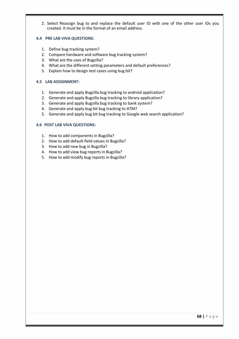
68 | P a g e
2. Select Reassign bug to and replace the default user ID with one of the other user IDs you
created. It must be in the format of an email address.
4.4 PRE LAB VIVA QUESTIONS:
1. Define bug tracking system? 2. Compare hardware and software bug tracking system? 3. What are the uses of Bugzilla? 4. What are the different setting parameters and default preferences? 5. Explain how to design test cases using bug bit?
4.5 LAB ASSIGNMENT:
1. Generate and apply Bugzilla bug tracking to android application? 2. Generate and apply Bugzilla bug tracking to library application? 3. Generate and apply Bugzilla bug tracking to bank system? 4. Generate and apply bug bit bug tracking to ATM? 5. Generate and apply bug bit bug tracking to Google web search application?
4.6 POST LAB VIVA QUESTIONS:
1. How to add components in Bugzilla? 2. How to add default field values in Bugzilla? 3. How to add new bug in Bugzilla? 4. How to add view bug reports in Bugzilla? 5. How to add modify bug reports in Bugzilla?
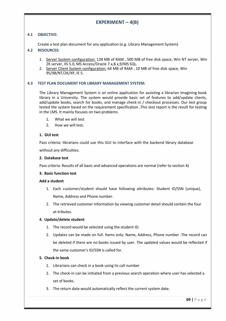
69 | P a g e
EXPERIMENT – 4(B)
4.1 OBJECTIVE:
Create a test plan document for any application (e.g. Library Management System)
4.2 RESOURCES:
1. Server System configuration: 128 MB of RAM , 500 MB of free disk space, Win NT server, Win 2K server, IIS 5.0, MS Access/Oracle 7.x,8.x,9/MS SQL.
2. Server Client System configuration: 64 MB of RAM , 10 MB of free disk space, Win 95/98/NT/2K/XP, IE 5.
4.3 TEST PLAN DOCUMENT FOR LIBRARY MANAGEMENT SYSTEM:
The Library Management System is an online application for assisting a librarian imagining book library in a University. The system would provide basic set of features to add/update clients, add/update books, search for books, and manage check-in / checkout processes. Our test group tested the system based on the requirement specification .This test report is the result for testing in the LMS. It mainly focuses on two problems
1. What we will test 2. How we will test.
1. GUI test
Pass criteria: librarians could use this GUI to interface with the backend library database
without any difficulties.
2. Database test
Pass criteria: Results of all basic and advanced operations are normal (refer to section 4)
3. Basic function test
Add a student
1. Each customer/student should have following attributes: Student ID/SSN (unique),
Name, Address and Phone number.
2. The retrieved customer information by viewing customer detail should contain the four
at-tributes.
4. Update/delete student
1. The record would be selected using the student ID.
2. Updates can be made on full. Items only: Name, Address, Phone number .The record can
be deleted if there are no books issued by user. The updated values would be reflected if
the same customer's ID/SSN is called for.
5. Check-in book
1. Librarians can check in a book using its call number
2. The check-in can be initiated from a previous search operation where user has selected a
set of books.
3. The return date would automatically reflect the current system date.
70 | P a g e
4. Any late fees would be computed as difference between due date and return date at rate
of 10 cents a day.
4.4 PRE LAB VIVA QUESTIONS:
1. Difference between domain and path testing? 2. What is testing blindness? 3. What is path instrumentation? 4. What are graph matrices? 5. Define slice and dice?
4.5 LAB ASSIGNMENT:
1. Design test plan document for e-library? 2. Design test plan document for credit card processing? 3. Design test plan document for ticket vending machine? 4. Design test plan document for Airport check-in business model? 5. Design test plan document for school management system?
4.6 POST LAB VIVA QUESTIONS:
1. What are domain bugs? 2. What is meant by predicate coverage? 3. Define path sensitization? 4. What C1, C2 Coverage? 5. Define Link marks and Link counters?
71 | P a g e
EXPERIMENT – 5 (A)
5.1 OBJECTIVE:
Study of Any Test Management Tool ( Test Director)
5.2 RESOURCES:
1. Server System configuration: 128 MB of RAM , 500 MB of free disk space, Win NT server, Win 2K server, IIS 5.0, MS Access/Oracle 7.x,8.x,9/MS SQL.
2. Server Client System configuration: 64 MB of RAM , 10 MB of free disk space, Win 95/98/NT/2K/XP, IE 5.
5.3 STUDY OF TEST DIRECTOR AND TEST MANAGEMENT TOOL:
Test Director is a global test management solution which provides communication, organization, documentation and structure to the testing project.
Test Director is used for
1. Mapping Requirements to User acceptance test cases 2. Test Planning by placing all the test cases and scripts in it. 3. Manual testing by defining test steps and procedures 4. Test Execution status 5. Defect Management
The Test Director Testing Process
Test Director offers an organized framework for testing applications before they are deployed. Since test plans evolve with new or modified application requirements, you need a central data repository for organizing and managing the testing process. TestDirector guides through the requirements specification, test planning, test execution, and defect tracking phases of the testing process.The Test Director testing process includes four phases:
Specifying Requirements
1. Requirements are linked to tests and defects to provide complete traceability and aid the decision-making process
2. See what percent of requirements are covered by tests 3. Each requirement in the tree is described in detail, and can include any relevant attachments.
The QA tester assigns the requirement a priority level which is taken into consideration when the test team creates the test plan
4. Import from Microsoft Word or third party RM tool
Planning Tests
1. The Test Plan Manager enables to divide application according to functionality. Application can be divided into units, or subjects, by creating a test plan tree.
2. Define subjects according to: Application functionality-such as editing, file operations, and reporting Type of testing-such as functional, user interface, performance, and load
3. As the tests are also linked to defects, this helps ensure compliance with testing requirements throughout the testing process.
Running Tests
72 | P a g e
As the application constantly changes, using test lab, run manual and automated tests in the project in order to locate defects and assess quality.
1. By creating test sets and choosing which tests to include in each set, test suite can be created.
A test set is a group of tests in a Test Director project database designed to achieve specific testing goals.
2. Tests can be run manually or scheduled to run automatically based on application
dependencies.
Tracking Defects Locating and repairing application defects efficiently is essential to the testing process. Defects can be detected and added during all stages of the testing process. In this phase you per-form the following tasks:
1. This tool features a sophisticated mechanism for tracking software defects, enabling Testing
Team and the project Team to monitor defects closely from initial detection until resolution
2. By linking Test Director to e-mail system, defect tracking information can be shared by all
Development and Management Teams, Testing and Wipro Software Quality Assurance personnel
System Requirements for Test Director Server System configuration : 128 MB of RAM , 500 MB of free disk space, Win NT server, Win 2K server, IIS 5.0, MS Access/Oracle 7.x,8.x,9/MS SQL Server Client System con-figuration : 64 MB of RAM , 10 MB of free disk space, Win 95/98/NT/2K/XP, IE 5 , Netscape 4.7
5.4 PRE LAB VIVA QUESTIONS:
1. Define test director? 2. What are the uses of test director? 3. What is testing process for test director? 4. What are the specification requirements for test director? 5. What are the test plans for test director?
5.5 LAB ASSIGNMENT:
1. Generate test cases using test director for web application? 2. Generate test cases using test director for online shopping? 3. Generate test cases using test director for ATM? 4. Generate test cases using test director for library application? 5. Generate test cases using test director for hospital management system?
5.6 POST LAB VIVA QUESTIONS:
1. Can we link test director to email system? 2. How can we track defects using test director? 3. Define defect management? 4. Explain test planning in test cases and scripts? 5. What is meant by global test management?
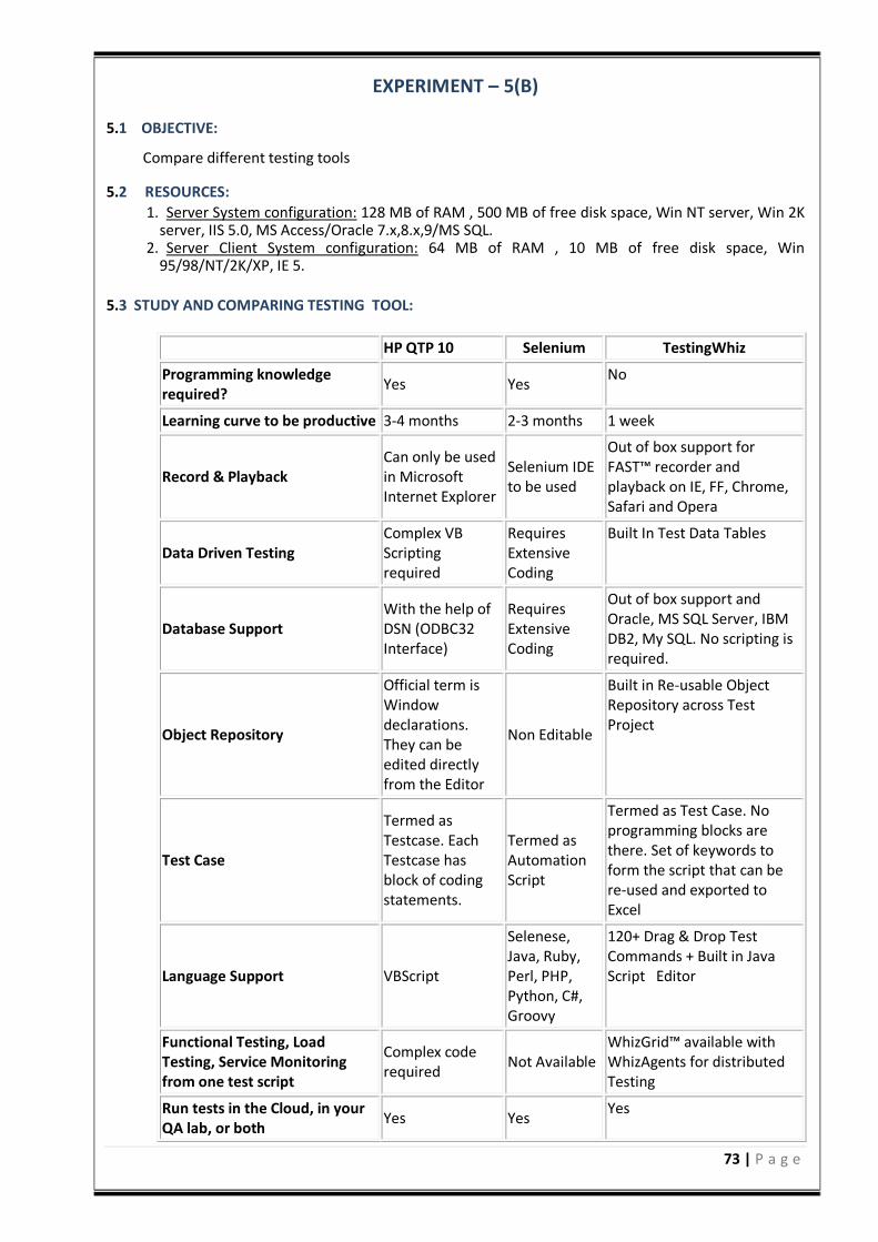
73 | P a g e
EXPERIMENT – 5(B) 5.1 OBJECTIVE:
Compare different testing tools 5.2 RESOURCES:
1. Server System configuration: 128 MB of RAM , 500 MB of free disk space, Win NT server, Win 2K server, IIS 5.0, MS Access/Oracle 7.x,8.x,9/MS SQL.
2. Server Client System configuration: 64 MB of RAM , 10 MB of free disk space, Win 95/98/NT/2K/XP, IE 5.
5.3 STUDY AND COMPARING TESTING TOOL:
HP QTP 10 Selenium TestingWhiz
Programming knowledge required?
Yes Yes No
Learning curve to be productive 3-4 months 2-3 months 1 week
Record & Playback Can only be used in Microsoft Internet Explorer
Selenium IDE to be used
Out of box support for FAST™ recorder and playback on IE, FF, Chrome, Safari and Opera
Data Driven Testing Complex VB Scripting required
Requires Extensive Coding
Built In Test Data Tables
Database Support With the help of DSN (ODBC32 Interface)
Requires Extensive Coding
Out of box support and Oracle, MS SQL Server, IBM DB2, My SQL. No scripting is required.
Object Repository
Official term is Window declarations. They can be edited directly from the Editor
Non Editable
Built in Re-usable Object Repository across Test Project
Test Case
Termed as Testcase. Each Testcase has block of coding statements.
Termed as Automation Script
Termed as Test Case. No programming blocks are there. Set of keywords to form the script that can be re-used and exported to Excel
Language Support VBScript
Selenese, Java, Ruby, Perl, PHP, Python, C#, Groovy
120+ Drag & Drop Test Commands + Built in Java Script Editor
Functional Testing, Load Testing, Service Monitoring from one test script
Complex code required
Not Available WhizGrid™ available with WhizAgents for distributed Testing
Run tests in the Cloud, in your QA lab, or both
Yes Yes Yes
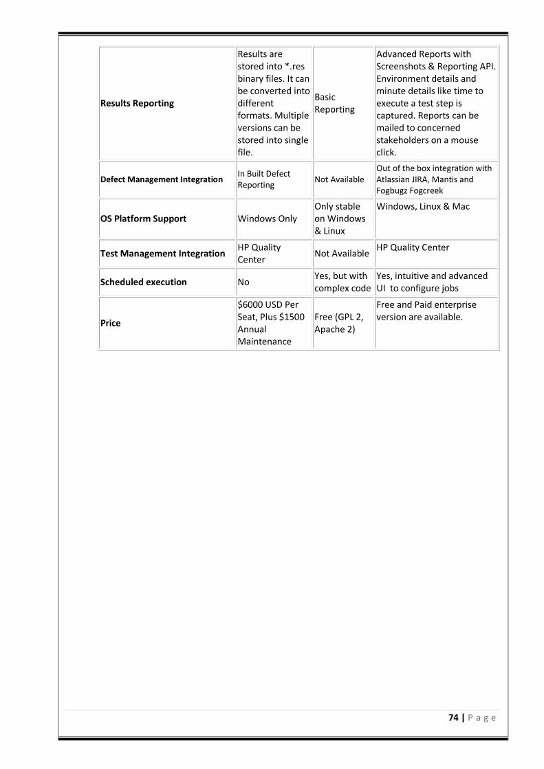
74 | P a g e
Results Reporting
Results are stored into *.res binary files. It can be converted into different formats. Multiple versions can be stored into single file.
Basic Reporting
Advanced Reports with Screenshots & Reporting API. Environment details and minute details like time to execute a test step is captured. Reports can be mailed to concerned stakeholders on a mouse click.
Defect Management Integration In Built Defect Reporting
Not Available Out of the box integration with Atlassian JIRA, Mantis and Fogbugz Fogcreek
OS Platform Support Windows Only Only stable on Windows & Linux
Windows, Linux & Mac
Test Management Integration HP Quality Center
Not Available HP Quality Center
Scheduled execution No Yes, but with complex code
Yes, intuitive and advanced UI to configure jobs
Price
$6000 USD Per Seat, Plus $1500 Annual Maintenance
Free (GPL 2, Apache 2)
Free and Paid enterprise version are available.
75 | P a g e
EXPERIMENT – 6(A) 6.1 OBJECTIVE:
Study of any open source testing tool (Test Link)
6.2 RESOURCES:
1. Server System configuration: 128 MB of RAM , 500 MB of free disk space, Win NT server, Win 2K server, IIS 5.0, MS Access/Oracle 7.x,8.x,9/MS SQL.
2. Server Client System configuration: 64 MB of RAM , 10 MB of free disk space, Win 95/98/NT/2K/XP, IE 5.
6.3 STUDY OF TEST LINK OPEN SOURCE TESTING TOOL:
Test link is an open source test management tool. It enables creation and organization of test cases and helps manage into test plan. Allows execution of test cases from test link itself. One can easily track test results dynamically, generate reports, generate test metrics, prioritize test cases and assign unfinished tasks. Its a web based tool with GUI, which provides an ease to develop test cases, organize test cases into test plans, execute these test cases and generate re-ports. Test link exposes API, written in PHP, can help generate quality assurance dashboards. The functions like AddTestCase ToTestPlan, Assign Requirements,Create TestCase etc. helps create and organize test cases per test plan. Functions like GetTestCasesForTestPlan, GetLastExecutionResult allows one to create quality assurance dashboard. TestLink enables easily to create and manage Test cases as well as organize them into Test plans. These Test plans allow team members to execute Test cases and track test results dynamically, generate reports, trace software requirements, prioritize and assign tasks. Read more about implemented features and try demo pages. Overall structure There are three cornerstones: Product, Test Plan and User. All other data are relations or attributes for this base. First, definition of a couple of terms that are used throughout the documentation. Products and Test Plans 1. Product: A Product is something that will exist forever in TestLink. Products will under-go many different versions throughout their lifetimes. Product includes Test Specification with Test Cases and should be sorted via Keywords. 2. Test Plan: Test Plans are created when you‘d like to execute test cases. Test plans can be made up of the test cases of one or many Products. Test Plan includes Builds, Test Case Suite and Test Results. 3. User: An User has a Role, that defines available TestLink features. Test Case Categorization TestLink breaks down the test case structure into three levels Components, Categories, and test cases. These levels are persisted throughout the application. 1. Component: Components are the parents of Categories. Each Component can have many 2. Categories. 3. Category: Categories are the parents of test cases. Each Category can have many test cases. 4. Test Case: Test cases are the fundamental piece of TestLink. 5. Test Specification: All Components, Categories and test cases within Product.
76 | P a g e
6. Test Case Suite: All Components, Categories and test cases within Test Plan. Test Specification Creating Test Cases Tester must follow this structure: Component, Category and test case. At first you create Component(s) for your Product. Component includes Categories. Category has the similar meaning but is second level of Test Specification and includes just Test Cases.User can also copy or move Test Cases. Test Cases have following parts: 1. Title: could include either short description or abbreviation (e.g. TL-USER-LOGIN) 2. Summary: should be really short; just for overview. 3. Steps: describe test scenario (input actions); can also include precondition and cleanup
information here. 4. Expected results: describe checkpoints and expected behavior a tested Product or system. Deleting Test Cases Test cases, Categories, and Components may be deleted from a test plan by users with lead permissions from the delete test cases screen. Deleting data may be useful when first creating a test plan since there are no results. However, Deleting test cases will cause the loss of all results associated with them. Therefore, extreme caution is recommended when using this functionality. Requirements relation Test cases could be related with software/system requirements as n to n. The functionality must be enabled for a Product. User can assign Test Cases and Requirements via link Assign Requirements in the main screen. Test Plans Test plan contains name, description, collection a chosen test cases, builds, test results, milestones, tester assignment and priority definition. Creating a new Test Plan Test Plans may be deleted from the Create test plan page (link Create Test Plan) by users with lead privileges. Test plans are the basis for test case execution. Test plans are made up of test cases imported from Products at a specific point of time. Test plans can only be created by users with lead privileges. Test plans may be created from other test plans. This allows users to create test plans from test cases that at a desired point in time. This may be necessary when creating a test plan for a patch. In order for a user to see a test plan they must have the proper rights. Rights may be assigned (by leads) in the define User/Project Rights section. This is an important thing to remember when users tell you they can‘t see the project they are working on. Test Execution Test execution is available when: 1. A Test Specification is written. 2. A Test Plan is created. 3. Test Case Suite (for the Test Plan) is defined.
77 | P a g e
4. A Build is created. 5. The Test plan is assigned to testers (otherwise they cannot navigate to this Test Plan). 6. Select a required Test Plan in main page and navigate to the Execute testlink. Left pane serves for navigation in Test Case Suite via tree menu, filtering and define a tested build. Test Status Execution is the process of assigning a result (pass, fail, blocked) to a test case for a specific build. Blocked‘ test case is not possible to test for some reason (e.g. a problem in configuration disallows to run a tested functionality). Insert Test results Test Results screen is shown via click on an appropriate Component, Category or test case in navigation pane. The title shows the current build and owner. The colored bar indicate status of the test case. Yellow box includes test scenario of the test case. Updated Test Cases: If users have the proper rights they can go to the Update modified testcase page through the link on main page. It is not necessary for users to update test cases if there has been a change (newer version or deleted). Advantages: 1. Easy in tracking test cases(search with keyword, test case id, version etc) 2. We can add our custom fields to test cases. 3. Allocating the work either test case creation/execution any kind of documents is easy 4. when a test cases is updated the previous version also can be tracked 5. We can generate results build wise 6. Test plans are created for builds and work allocations can be done. Report, is one of the awesome functionality present in the Test link, it generates reports in desired format like HTML/ CSV /Excel and we can create graphs too. And the above all is done on the privileges based which is an art of the testlink and i liked this feature much Example of TestLink workflow: 1. Administrator create a Product Fast Food‖ and a user Adam with rights leader and Bela with
rights Senior tester. 2. Adam imports Software Requirements and for part of these requirements generates empty Test cases. 3. Bela describe test scenario of these Test cases that are organized according to Components and
Categories. 4. Adam creates Keyword: Regression‖ and assigns this keyword to ten of these test cases. 5. Adam creates a Test Plan Fish & Chips, Build Fish 0.1 and add Test Cases with keywords Regression. 6. Adam and Bela execute and record the testing with result: 5 passed, 1 failed and 4 are blocked. 7. Developers make a new build Fish 0.2 and Bela tests the failed and blocked test cases only.
Exceptionally all these five Test cases passed. 8. Manager would like to see results. Administrator explains him that he can create account himself
on the login page. Manager does it. He has Guestrights and could see results and Test cases. He can see that everything passed in overall report and problems in build Fish 0.1 in a report for particular Build. But he can change nothing.
6.4 PRE LAB VIVA QUESTIONS:
78 | P a g e
1. Define test link? 2. Difference between product and test plan? 3. Explain test case categorization? 4. What is test case specification? 5. How to delete test case in Test Link?
6.5 LAB ASSIGNMENT: 1. Generate test cases for library application using Test Link? 2. Generate test cases for ATM application using Test Link? 3. Generate test cases for bank application using Test Link? 4. Generate test cases for online shopping using Test Link? 5. Generate test cases for online credit card processing using Test Link?
6.6 POST LAB VIVA QUESTIONS:
1. When a test execution is available in Test Link? 2. Explain about test status 3. What are the advantages of Test Link? 4. How to create test cases in Test Link? 5. Difference between Test Link and other test techniques?
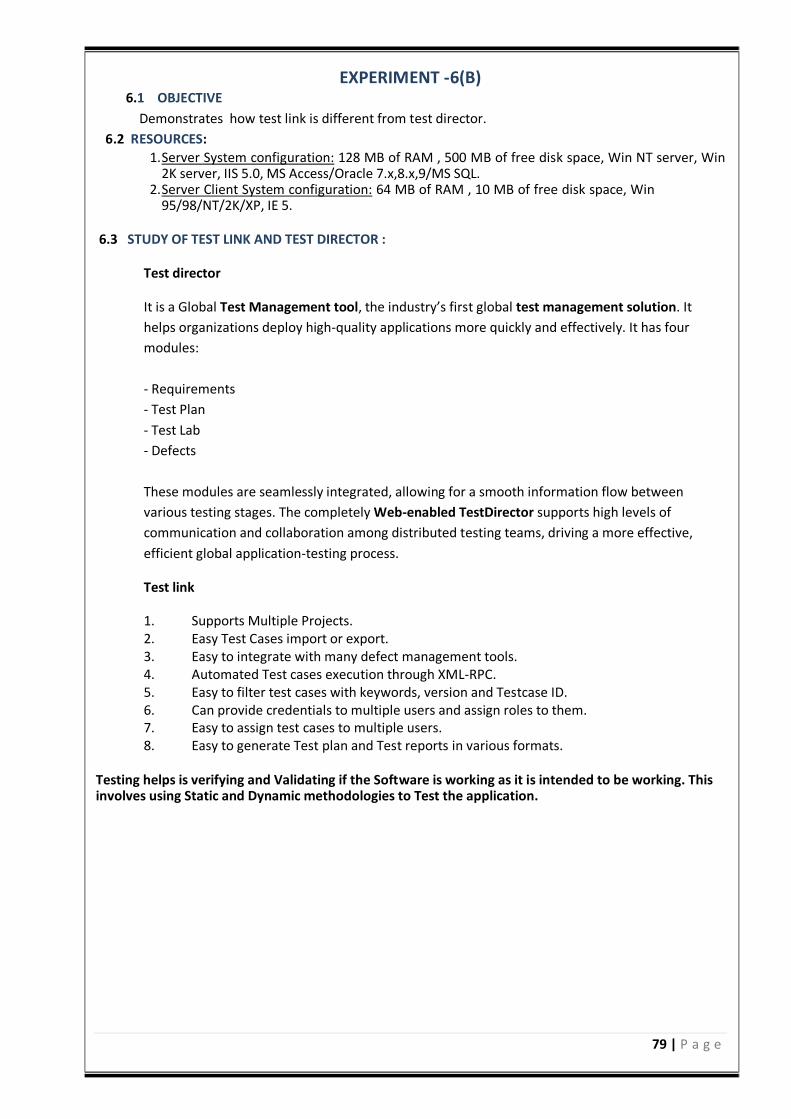
79 | P a g e
EXPERIMENT -6(B) 6.1 OBJECTIVE
Demonstrates how test link is different from test director.
6.2 RESOURCES:
1. Server System configuration: 128 MB of RAM , 500 MB of free disk space, Win NT server, Win 2K server, IIS 5.0, MS Access/Oracle 7.x,8.x,9/MS SQL.
2. Server Client System configuration: 64 MB of RAM , 10 MB of free disk space, Win 95/98/NT/2K/XP, IE 5.
6.3 STUDY OF TEST LINK AND TEST DIRECTOR :
Test director
It is a Global Test Management tool, the industry’s first global test management solution. It
helps organizations deploy high-quality applications more quickly and effectively. It has four
modules:
- Requirements
- Test Plan
- Test Lab
- Defects
These modules are seamlessly integrated, allowing for a smooth information flow between
various testing stages. The completely Web-enabled TestDirector supports high levels of
communication and collaboration among distributed testing teams, driving a more effective,
efficient global application-testing process.
Test link
1. Supports Multiple Projects. 2. Easy Test Cases import or export. 3. Easy to integrate with many defect management tools. 4. Automated Test cases execution through XML-RPC. 5. Easy to filter test cases with keywords, version and Testcase ID. 6. Can provide credentials to multiple users and assign roles to them. 7. Easy to assign test cases to multiple users. 8. Easy to generate Test plan and Test reports in various formats.
Testing helps is verifying and Validating if the Software is working as it is intended to be working. This involves using Static and Dynamic methodologies to Test the application.
80 | P a g e
REFERENCES 1. Testing Computer Software, 2nd Edition by Cem Kaner, Jack Falk and Hung 2. Effective Software Testing Methodology by Willian E.Perry 3. Software Testing Foundations: A Study Guide for the Certified Tester Exam (Rockynook Computing) by Andreas Spillner, Tilo Linz and Hans Schaefe. 4. Software Testing: A Craftsman's Approach, Third Edition by Paul Jorgensen

81 | P a g e
WEB TECHNOLOGIES LAB
82 | P a g e
WEB TECHNOLOGIES LABORATORY
OBJECTIVE:
Presenting information over internet in form of web pages is the best way of reaching to
all corners of world. This laboratory aims at giving knowledge about creating web pages and also
about different web programming concepts, technologies.
OUTCOMES: Upon the completion of Operating Systems practical course, the student will be able to:
1. Demonstrate the ability to retrieve data from a database and present it in a web page.
2. Demonstrate competency in the use of common HTML code.
3. Demonstrate competency using FTP to transfer web pages to a server.
4. Construct pages that meet guidelines for efficient download.
5. Construct pages that meet the needs of an identified audience.
6. Construct efficient file structure for web sites.
7. Evaluate the functions of specific types of web pages in relationship to an entire web site.
8. Design electronic text and web pages that include the standard textual components needed
on web pages.
9. Create web pages that meet accessibility needs of those with physical disabilities.
10. Understand how CSS will affect web page creation.
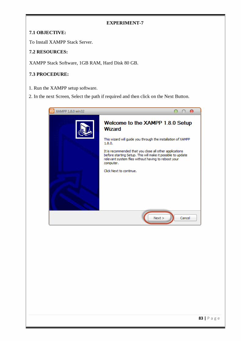
83 | P a g e
EXPERIMENT-7
7.1 OBJECTIVE:
To Install XAMPP Stack Server.
7.2 RESOURCES:
XAMPP Stack Software, 1GB RAM, Hard Disk 80 GB.
7.3 PROCEDURE:
1. Run the XAMPP setup software.
2. In the next Screen, Select the path if required and then click on the Next Button.
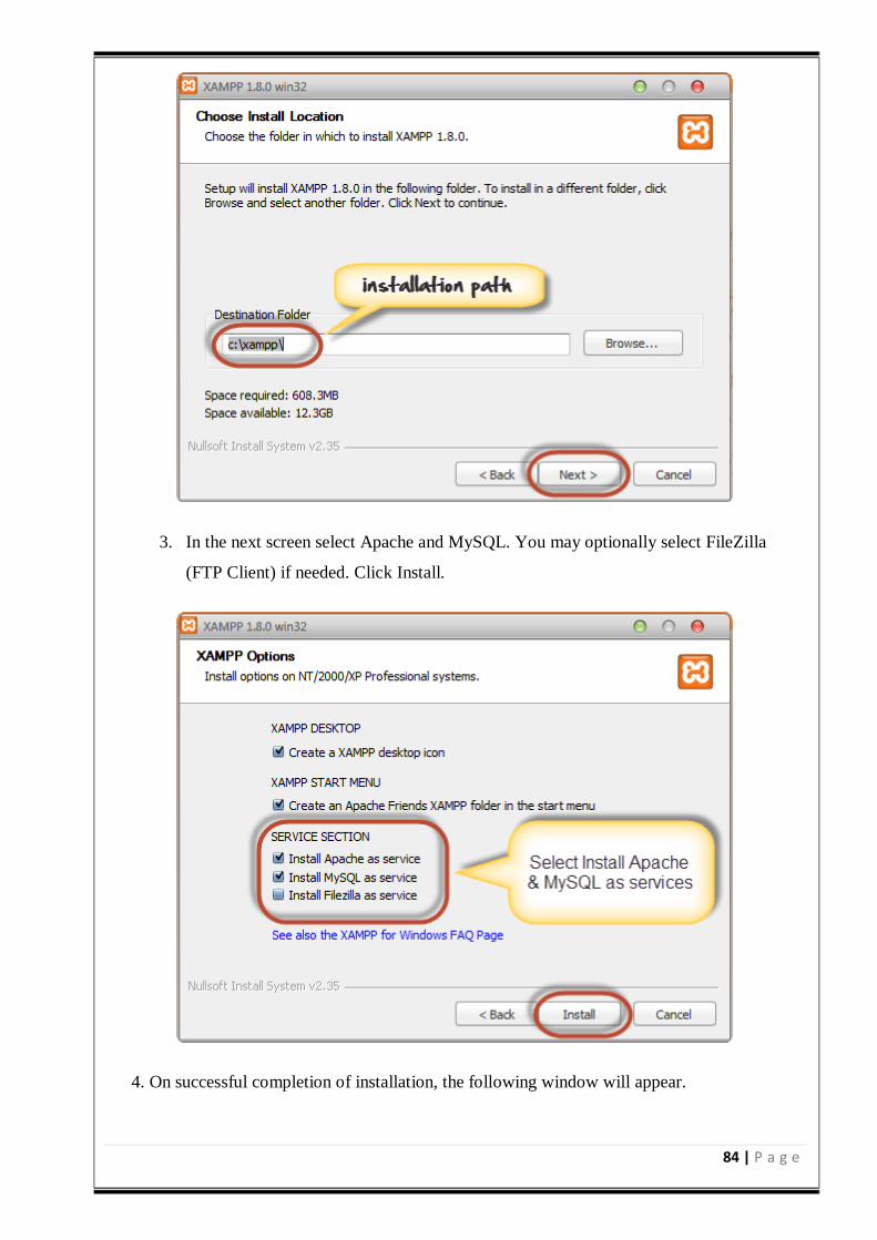
84 | P a g e
3. In the next screen select Apache and MySQL. You may optionally select FileZilla
(FTP Client) if needed. Click Install.
4. On successful completion of installation, the following window will appear.
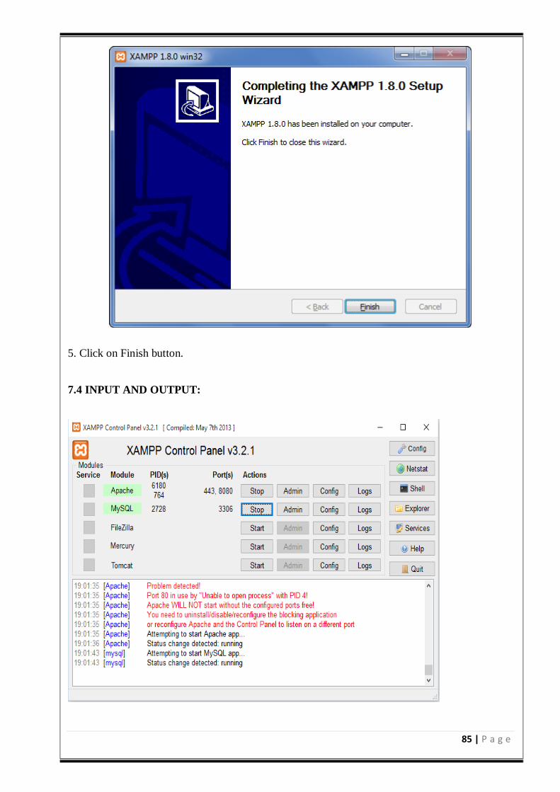
85 | P a g e
5. Click on Finish button.
7.4 INPUT AND OUTPUT:
86 | P a g e
7.5 PRE LAB VIVA QUESTIONS:
1. What is XAMPP stack?
2. What is setup file?
3. What is client side scripting?
4. What is server side scripting?
7.6 LAB ASSIGNMENT:
1. Install WAMP Stack Server?
2. Install LAMP Stack Server?
7.7 POST LAB VIVA QUESTIONS:
1. What is Mysql?
2. Why is the name as Mysql?
3. What is the usage of apache tomcat server?
4. How to run the PHP file?
87 | P a g e
EXPERIMENT-8
8.1 OBJECTIVE:
To accept a number from one text field in the range of 0 to 999 and shows it in another text field
in words. If the number is out of range, it should show “out of range” and if it is not a number, it
should show “not a number” message in the result box.
8.2 RESOURCES: XAMPP Stack, 1GB RAM, Hard Disk 80 GB
8.3 PROGRAM LOGIC:
1. Create a HTML file.
2. Read a number in one text field and display that number name in another text field.
3. Include the JavaScript to convert number into words.
8.4 PROCEDURE:
To execute a PHP program:
1. Open XAMPP control Panel then start Apache Server and Mysql.
2. Open Notepad++ and Save the php program in htdocs folder of XAMPP.
3. To run the php file open the browser and type the following URL
localhost:90/directory name/filename
8.5 SOURCE CODE:
<html>
<head>
<script type="text/javascript">
var th = ['','thousand','million', 'billion','trillion'];
var dg=['zero','one','two','three','four','five','six','seven','eight','nine'];
var tn=['ten','eleven','twelve','thirteen','fourteen','fifteen','sixteen','seventeen','eighteen','nineteen'];
var tw=['twenty','thirty','forty','fifty','sixty','seventy','eighty','ninety'];
function change()
var numString=document.getElementById('anumber').value;
var output=towords(numString);
88 | P a g e
document.getElementById('aresult').value=output;
function towords(s)
s = s.toString();
if (s != parseFloat(s)) return 'not a number';
var x = s.indexOf('.');
if (x == -1) x = s.length;
if (x > 3) return 'too big';
var n = s.split('');
var str = '';
var sk = 0;
for (var i=0; i < x; i++)
if ((x-i)%3==2)
if (n[i] == '1')
str += tn[Number(n[i+1])] + ' ';
i++;
sk=1;
else if (n[i]!=0)
str += tw[n[i]-2] + ' ';
sk=1;
else if (n[i]!=0)
str += dg[n[i]] +' ';
if ((x-i)%3==0) str += 'hundred ';
sk=1;
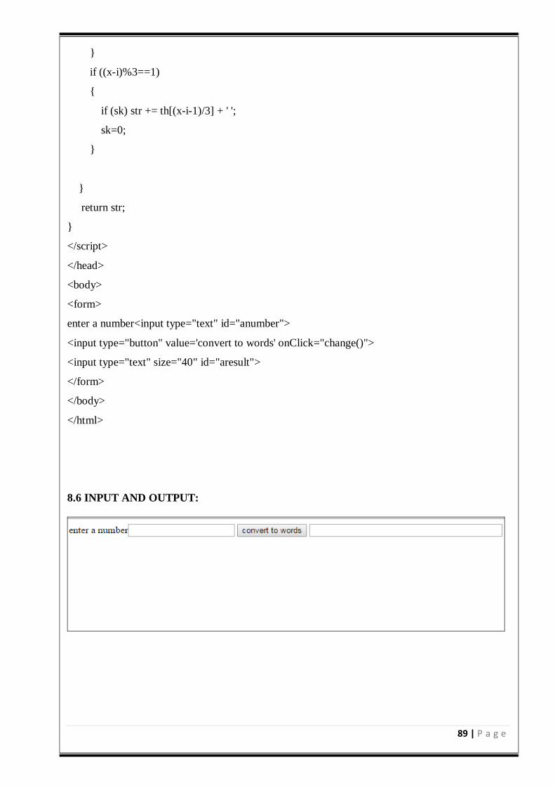
89 | P a g e
if ((x-i)%3==1)
if (sk) str += th[(x-i-1)/3] + ' ';
sk=0;
return str;
</script>
</head>
<body>
<form>
enter a number<input type="text" id="anumber">
<input type="button" value='convert to words' onClick="change()">
<input type="text" size="40" id="aresult">
</form>
</body>
</html>
8.6 INPUT AND OUTPUT:
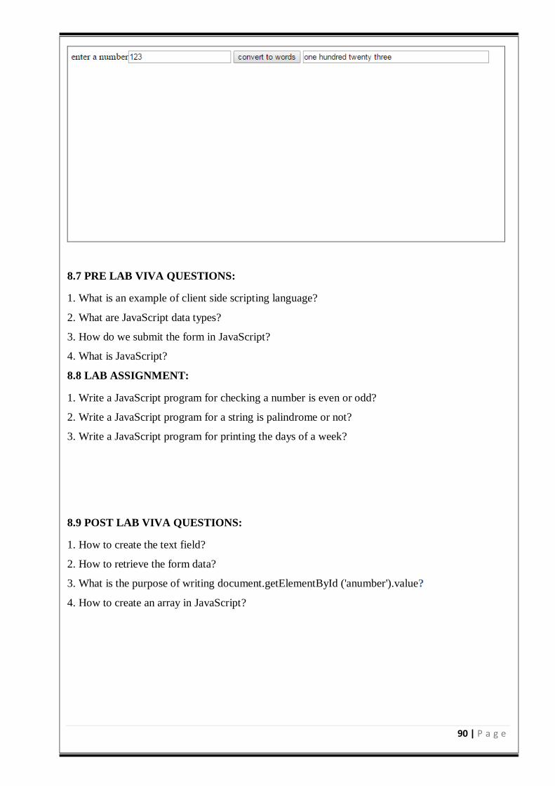
90 | P a g e
8.7 PRE LAB VIVA QUESTIONS:
1. What is an example of client side scripting language?
2. What are JavaScript data types?
3. How do we submit the form in JavaScript?
4. What is JavaScript?
8.8 LAB ASSIGNMENT:
1. Write a JavaScript program for checking a number is even or odd?
2. Write a JavaScript program for a string is palindrome or not?
3. Write a JavaScript program for printing the days of a week?
8.9 POST LAB VIVA QUESTIONS:
1. How to create the text field?
2. How to retrieve the form data?
3. What is the purpose of writing document.getElementById ('anumber').value?
4. How to create an array in JavaScript?
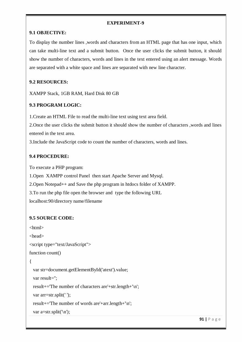
91 | P a g e
EXPERIMENT-9
9.1 OBJECTIVE:
To display the number lines ,words and characters from an HTML page that has one input, which
can take multi-line text and a submit button. Once the user clicks the submit button, it should
show the number of characters, words and lines in the text entered using an alert message. Words
are separated with a white space and lines are separated with new line character.
9.2 RESOURCES: XAMPP Stack, 1GB RAM, Hard Disk 80 GB
9.3 PROGRAM LOGIC:
1.Create an HTML File to read the multi-line text using text area field.
2.Once the user clicks the submit button it should show the number of characters ,words and lines
entered in the text area.
3.Include the JavaScript code to count the number of characters, words and lines.
9.4 PROCEDURE:
To execute a PHP program:
1.Open XAMPP control Panel then start Apache Server and Mysql.
2.Open Notepad++ and Save the php program in htdocs folder of XAMPP.
3.To run the php file open the browser and type the following URL
localhost:90/directory name/filename
9.5 SOURCE CODE:
<html>
<head>
<script type="text/JavaScript">
function count()
var str=document.getElementById('atext').value;
var result='';
result+='The number of characters are'+str.length+'\n';
var arr=str.split(' ');
result+='The number of words are'+arr.length+'\n';
var a=str.split('\n');
92 | P a g e
result+='The number of lines are'+a.length;
alert(result);
</script>
</head>
<body>
<form>
<textarea rows='40' cols='70' id='atext'>
</textarea>
<input type="submit" value="submit" onclick="count()">
</form>
</body>
</html>
9.6 INPUT AND OUTPUT:
9.7 PRE LAB VIVA QUESTIONS:
1. How to create the HTML document?
2. How to create the text area in an HTML document?
3. How to create the submit button in an HTML document?
93 | P a g e
4. How to create function in an HTML document?
9.8 LAB ASSIGNMENT:
1. Write an HTML program for creating two frames?
2. Write a HTML program for adding images with HTML.
3. Write a HTML Program to demonstrate Cell Spacing and Cell Padding in a XHTML Table?
9.9 POST LAB VIVA QUESTIONS:
1. What is the purpose of str.split(' ')?
2. What is the purpose of str.split('\n')?
3. How to find the length of the array?
4. How to create the alert message?

94 | P a g e
EXPERIMENT-10
10.1 OBJECTIVE:
To print the capital of country from HTML page that contains a selection box with a list of 5
countries. When the user selects a country, its capital should be printed next to the list. Add CSS
to customize the properties of the font of the capital (color, bold and font size)
10.2 RESOURCES:
XAMPP Stack, 1GB RAM, Hard Disk 80 GB
10.3 PROGRAM LOGIC:
1. Create an HTML file from which select the country from the selection box.
2. Once the user selects the country it should display the selected country’s capital.
3. Include the JavaScript display the capital for selected country.
4. Create the CSS file which includes the properties like color, bold and font size.
10.4 PROCEDURE:
To execute a PHP program:
1.Open XAMPP control Panel then start Apache Server and Mysql.
2.Open Notepad++ and Save the php program in htdocs folder of XAMPP.
3.To run the php file open the browser and type the following URL
localhost:90/directory name/filename
10.5 SOURCE CODE:
<html>
<title>Fourth Program</title>
<head>
<script type="text/JavaScript">
function OnDropDownChange(dropDown)
var selectedValue = dropDown.options[dropDown.selectedIndex].value;
document.getElementById("txtSelectedCapital").innerHTML = selectedValue;
</script>
</head>
<body>
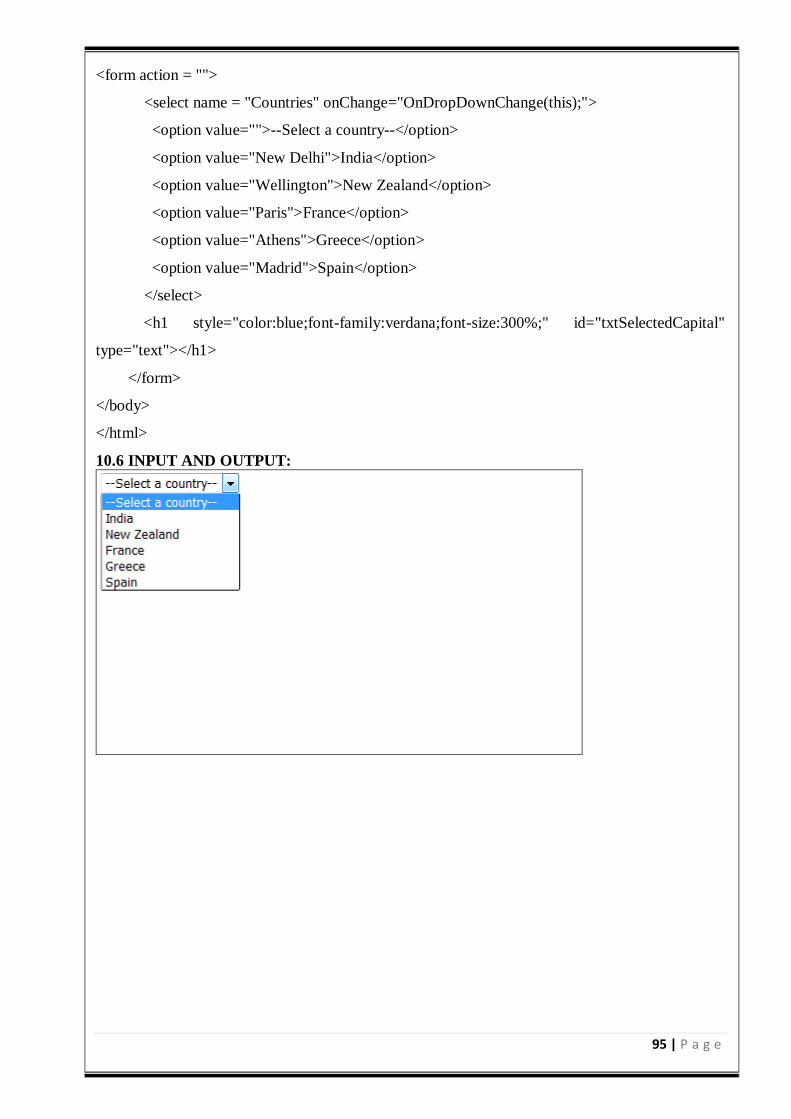
95 | P a g e
<form action = "">
<select name = "Countries" onChange="OnDropDownChange(this);">
<option value="">--Select a country--</option>
<option value="New Delhi">India</option>
<option value="Wellington">New Zealand</option>
<option value="Paris">France</option>
<option value="Athens">Greece</option>
<option value="Madrid">Spain</option>
</select>
<h1 style="color:blue;font-family:verdana;font-size:300%;" id="txtSelectedCapital"
type="text"></h1>
</form>
</body>
</html>
10.6 INPUT AND OUTPUT:
96 | P a g e
10.7 PRE LAB VIVA QUESTIONS:
1. How do you insert a comment in html?
2. What are some of the common lists that can be used when designing a page?
3. How do you create links to sections within the same page?
4. Does a hyperlink apply to text only?
10.8 LAB ASSIGNMENT:
1. Write a HTML Program to demonstrate Form Fields.
2. Write a HTML Demonstration of Navigation through various frames
3. To create a php program to demonstrate the different file handling methods.
10.9 POST LAB VIVA QUESTIONS:
1. If the user’s operating system does not support the needed character, how can the symbol be
represented?
2. How do you change the number type in the middle of a list?
3. Is it possible to set specific colors for table borders?
4. How do you create a link that will connect to another web page when clicked?
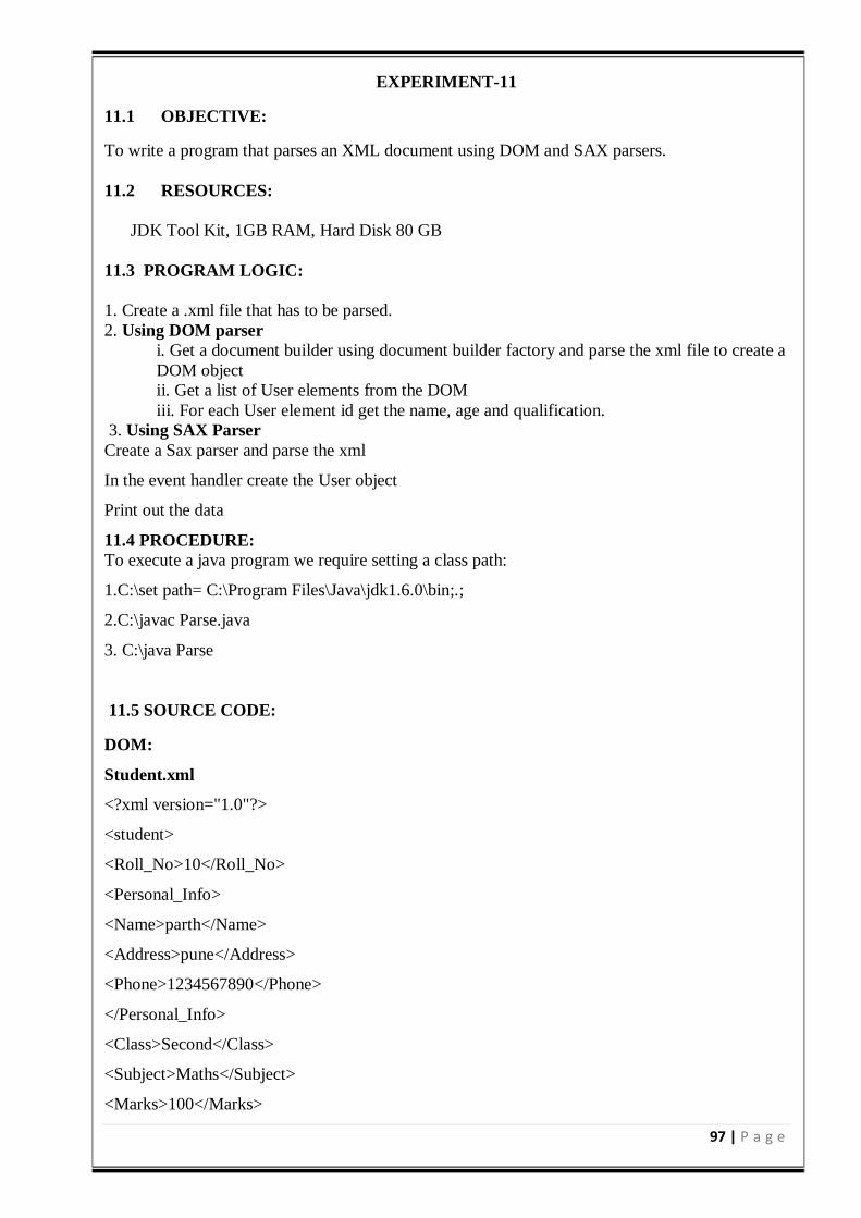
97 | P a g e
EXPERIMENT-11
11.1 OBJECTIVE:
To write a program that parses an XML document using DOM and SAX parsers.
11.2 RESOURCES:
JDK Tool Kit, 1GB RAM, Hard Disk 80 GB
11.3 PROGRAM LOGIC:
1. Create a .xml file that has to be parsed.
2. Using DOM parser
i. Get a document builder using document builder factory and parse the xml file to create a
DOM object
ii. Get a list of User elements from the DOM
iii. For each User element id get the name, age and qualification.
3. Using SAX Parser
Create a Sax parser and parse the xml
In the event handler create the User object
Print out the data
11.4 PROCEDURE:
To execute a java program we require setting a class path:
1.C:\set path= C:\Program Files\Java\jdk1.6.0\bin;.;
2.C:\javac Parse.java
3. C:\java Parse
11.5 SOURCE CODE:
DOM:
Student.xml
<?xml version="1.0"?>
<student>
<Roll_No>10</Roll_No>
<Personal_Info>
<Name>parth</Name>
<Address>pune</Address>
<Phone>1234567890</Phone>
</Personal_Info>
<Class>Second</Class>
<Subject>Maths</Subject>
<Marks>100</Marks>
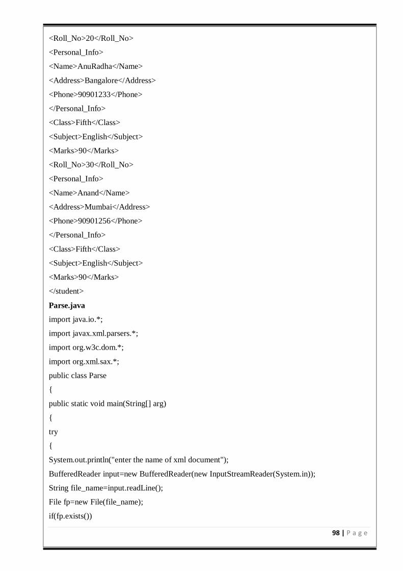
98 | P a g e
<Roll_No>20</Roll_No>
<Personal_Info>
<Name>AnuRadha</Name>
<Address>Bangalore</Address>
<Phone>90901233</Phone>
</Personal_Info>
<Class>Fifth</Class>
<Subject>English</Subject>
<Marks>90</Marks>
<Roll_No>30</Roll_No>
<Personal_Info>
<Name>Anand</Name>
<Address>Mumbai</Address>
<Phone>90901256</Phone>
</Personal_Info>
<Class>Fifth</Class>
<Subject>English</Subject>
<Marks>90</Marks>
</student>
Parse.java
import java.io.*;
import javax.xml.parsers.*;
import org.w3c.dom.*;
import org.xml.sax.*;
public class Parse
public static void main(String[] arg)
try
System.out.println("enter the name of xml document");
BufferedReader input=new BufferedReader(new InputStreamReader(System.in));
String file_name=input.readLine();
File fp=new File(file_name);
if(fp.exists())
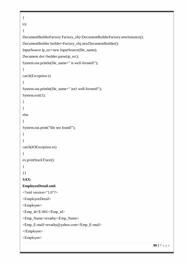
99 | P a g e
try
DocumentBuilderFactory Factory_obj=DocumentBuilderFactory.newInstance();
DocumentBuilder builder=Factory_obj.newDocumentBuilder();
InputSource ip_src=new InputSource(file_name);
Document doc=builder.parse(ip_src);
System.out.println(file_name+" is well-formed!");
catch(Exception e)
System.out.println(file_name+" isn't well-formed!");
System.exit(1);
else
System.out.print("file not found!");
catch(IOException ex)
ex.printStackTrace();
SAX:
EmployeeDetail.xml:
<?xml version="1.0"?>
<EmployeeDetail>
<Employee>
<Emp_id>E-001</Emp_id>
<Emp_Name>revathy</Emp_Name>
<Emp_E-mail>[email protected]</Emp_E-mail>
</Employee>
<Employee>
100 | P a g e
<Emp_id>E-002</Emp_id>
<Emp_Name>vinod</Emp_Name>
<Emp_E-mail>[email protected]</Emp_E-mail>
</Employee>
<Employee>
<Emp_id>E-001</Emp_id>
<Emp_Name>deepak</Emp_Name>
<Emp_E-mail>[email protected]</Emp_E-mail>
</Employee>
</EmployeeDetail>
SAXParserCheck.java:
import org.xml.sax.*;
import org.xml.sax.helpers.*;
import java.io.*;
public class SAXParserCheck
public static void main(String[]args)throws IOException
BufferedReader bf=new BufferedReader(new InputStreamReader(System.in));
System.out.print("enter XML file name :");
String xmlfile=bf.readLine();
SAXParserCheck par=new SAXParserCheck(xmlfile);
public SAXParserCheck(String str)
try
File file=new File(str);
if(file.exists())
XMLReader reader=XMLReaderFactory.createXMLReader();
reader.parse(str);
System.out.println(str+" is well-formed!");
else
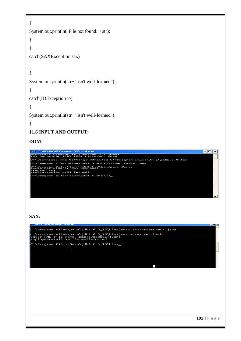
101 | P a g e
System.out.println("File not found:"+str);
catch(SAXException sax)
System.out.println(str+" isn't well-formed");
catch(IOException io)
System.out.println(str+" isn't well-formed");
11.6 INPUT AND OUTPUT:
DOM:
SAX:
102 | P a g e
11.7 PRE LAB VIVA QUESTIONS:
1. Is Java purely object oriented language?
2. How to create an object in java language?
3. How to display the string in java language?
4. What is the purpose of java.io.* package?
11.8 LAB ASSIGNMENT:
1. Write a program to reverse a number using Java language?
2. Write a program for linear search using Java language?
3. Write a program to check a number is even or odd using Java language?
11.9 POST LAB VIVA QUESTIONS:
1. How to handle the exceptions in java?
2. How to catch exceptions using java language?
3. How to read the XML file using java language?
4. How many types of parsers we have in XML?
103 | P a g e
EXPERIMENT-12(i)
12.1 OBJECTIVE:
To validate the user login using PHP and database.
12.2 RESOURCES:
XAMPP Stack, 1GB RAM, Hard Disk 80 GB
12.3 PROGRAM LOGIC:
1. Create the user database and table along with the user name and password as the attributes.
2. Create an HTML File to retrieve user name and password.
3. Create PHP file to retrieve the data from the database and HTML File.
4. Authenticate the user name and password if it is the valid user the display as successful login
otherwise display failure message.
12.4 PROCEDURE:
To execute a PHP program:
1. Open XAMPP control Panel then start Apache Server and Mysql.
2. Open Notepad++ and Save the php program in htdocs folder of XAMPP.
3. To run the php file open the browser and type the following URL
localhost:90/directory name/filename
12.5 SOURCE CODE:
<html>
<body>
<form enctype="multipart/form-data" action="database.php" method="post">
username:
<input type="text" name="username">
<br>
password:
<input type="password" name="password" maxlength="10">
<br>
<input type="submit" name="submit">
</form>
</body>
</html>
database.php

104 | P a g e
<?php
$name=$_REQUEST['username'];
$pass=$_REQUEST['password'];
$dbhost = 'localhost';
$dbuser = 'root';
$dbpass = 'santosh';
$conn = mysql_connect($dbhost, $dbuser, $dbpass);
if(! $conn )
die('Could not connect: ' . mysql_error());
$sql = 'SELECT username, password FROM user_detail';
mysql_select_db('user_login');
$retval = mysql_query( $sql, $conn );
if(! $retval )
die('Could not get data: ' . mysql_error());
while($row = mysql_fetch_array($retval, MYSQL_ASSOC))
if($name==$row['username'] && $pass==$row['password'])
echo("login sucesses");
return true;
else
echo("invalid username and paasword ");
return false;
?>
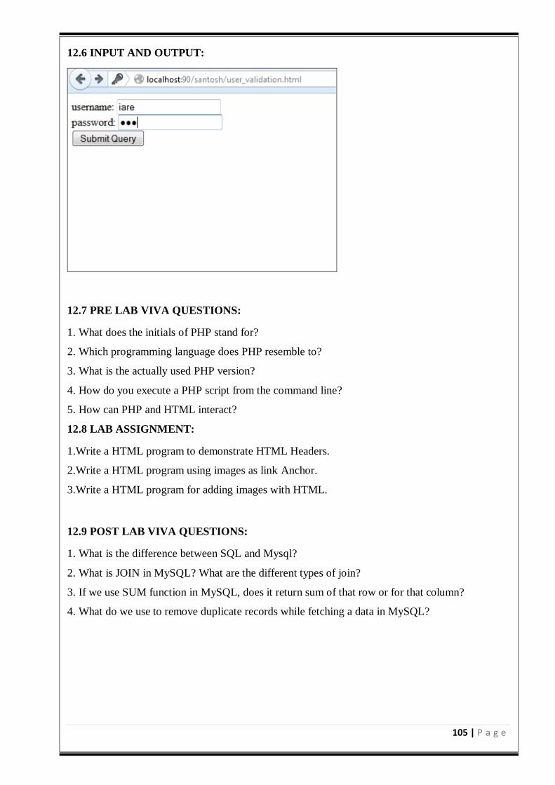
105 | P a g e
12.6 INPUT AND OUTPUT:
12.7 PRE LAB VIVA QUESTIONS:
1. What does the initials of PHP stand for?
2. Which programming language does PHP resemble to?
3. What is the actually used PHP version?
4. How do you execute a PHP script from the command line?
5. How can PHP and HTML interact?
12.8 LAB ASSIGNMENT:
1.Write a HTML program to demonstrate HTML Headers.
2.Write a HTML program using images as link Anchor.
3.Write a HTML program for adding images with HTML.
12.9 POST LAB VIVA QUESTIONS:
1. What is the difference between SQL and Mysql?
2. What is JOIN in MySQL? What are the different types of join?
3. If we use SUM function in MySQL, does it return sum of that row or for that column?
4. What do we use to remove duplicate records while fetching a data in MySQL?
106 | P a g e
EXPERIMENT-12(ii)
12.1 OBJECTIVE:
To validate the user login using PHP and XML.
12.2 RESOURCES:
XAMPP Stack, 1GB RAM, Hard Disk 80 GB
12.3 PROGRAM LOGIC:
1. Create the XML file with the tags user name and password.
2. Create an HTML File to retrieve user name and password.
3. Create PHP file to retrieve the data from the XML and HTML File.
4. Authenticate the user name and password if it is the valid user the display as successful login
otherwise display failure message.
12.4 PROCEDURE:
To execute a PHP program:
1. Open XAMPP control Panel then start Apache Server and Mysql.
2. Open Notepad++ and Save the php program in htdocs folder of XAMPP.
3. To run the php file open the browser and type the following URL
localhost:90/directory name/filename
12.5 SOURCE CODE:
html file
<html>
<body>
<form action="database.php" method="post">
username:
<input type="text" name="username">
<br>
password:
<input type="password" name="password" maxlength="10">
<br>
<input type="submit" name="submit">
</form>
</body>
</html>
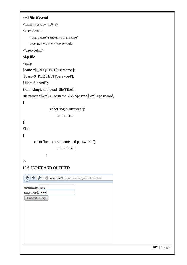
107 | P a g e
xml file-file.xml
<?xml version=”1.0”?>
<user-detail>
<username>santosh</username>
<password>iare</password>
</user-detail>
php file
<?php
$name=$_REQUEST['username'];
$pass=$_REQUEST['password'];
$file=”file.xml”;
$xml=simplexml_load_file($file);
If($name==$xml->username && $pass==$xml->password)
echo("login sucesses");
return true;
Else
echo("invalid username and paasword ");
return false;
?>
12.6 INPUT AND OUTPUT:
108 | P a g e
12.7 PRE LAB VIVA QUESTIONS:
1. Whether root element is required for XML? If so, how many root elements are required?
2. What are the disadvantages of xml?
3. Is there a way to describe XML data?
4. What is well formed XML document?
12.8 LAB ASSIGNMENT:
1. Write a program to create a CD catalog using XML file.
2. To create an XSL style sheet to display the data in the xml using html table.
3. Write an XML file which will display the Book information.
It includes the following:
1) Title of the book
2) Author Name
3) ISBN number
4) Publisher name
5) Edition
6) Price
Write an Internal Document Type Definition (DTD) to validate the above XML file.
12.9 POST LAB VIVA QUESTIONS:
1. How to read the data from the controls.
2. Why do we use multipart/form-data in html form?
3. What function do we use to find length of string, and length of array?
4. How to display the form data in php?
109 | P a g e
EXPERIMENT-12(iii)
12.1 OBJECTIVE:
To develop simple calculator web application.
12.2 RESOURCES:
XAMPP Stack, 1GB RAM, Hard Disk 80 GB
12.3 PROGRAM LOGIC:
1.Create an HTML file to read two variables and operator.
2.Create an PHP file to compute the arithmetic operation.
3.Dispaly the result.
12.4 PROCEDURE:
To execute a PHP program:
1. Open XAMPP control Panel then start Apache Server and Mysql.
2. Open Notepad++ and Save the php program in htdocs folder of XAMPP.
3. To run the php file open the browser and type the following URL
localhost:90/directory name/filename
12.5 SOURCE CODE:
cal.html
<html>
<body>
<form method="POST" action="process.php">
NO1:
<input type="text" name="num1" id="num1">
<br>
NO2:
<input type="text" name="num2" id="num2">
<br>
<select name = "func">
<option value="+">Add [+]</option>
<option value="-">Subtract[-]</option>
<option value="*">Multiple[*]</option>
<option value="/">Divide[/]</option>
110 | P a g e
<option value=”%”>modulus</option>
</select>
<input type="submit" name="submit" value="Submit" >
</form
</body>
</html>
process.php
<?php
$num1 = ($_POST['num1']);
$num2 = ($_POST['num2']);
$func= ($_POST['func']);
if(is_numeric($num1) &&is_numeric($num2) )
if($func != null)
switch($func)
case "+" : $result= $num1 + $num2; break;
case "-" : $result= $num1 - $num2; break;
case "*" : $result= $num1 * $num2; break;
case "/" : $result= $num1 / $num2; break;
case "%" : $result= $num1 % $num2; break;
echo("calculation result: ". $result);
?>
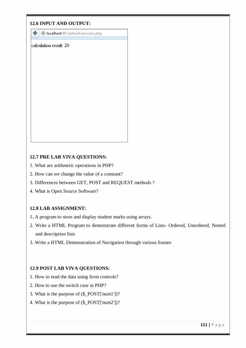
111 | P a g e
12.6 INPUT AND OUTPUT:
12.7 PRE LAB VIVA QUESTIONS:
1. What are arithmetic operations in PHP?
2. How can we change the value of a constant?
3. Differences between GET, POST and REQUEST methods ?
4. What is Open Source Software?
12.8 LAB ASSIGNMENT:
1. A program to store and display student marks using arrays.
2. Write a HTML Program to demonstrate different forms of Lists- Ordered, Unordered, Nested
and description lists
3. Write a HTML Demonstration of Navigation through various frames
12.9 POST LAB VIVA QUESTIONS:
1. How to read the data using form controls?
2. How to use the switch case in PHP?
3. What is the purpose of ($_POST['num1'])?
4. What is the purpose of ($_POST['num2'])?
112 | P a g e
EXPERIMENT-12(iv)
12.1 OBJECTIVE:
To validate age attribute, if age is less than 18 then display a message the user is not authorized to
visit this site otherwise a welcome message should be displayed using PHP.
12.2 RESOURCES:
XAMPP Stack, 1GB RAM, Hard Disk 80 GB
12.3 PROGRAM LOGIC:
1Create an HTML file to read the age and username.
2. Create a PHP file to check the user age.
3. If age>18 then display a message, welcome to the site otherwise display not authorized to this
site.
12.4 PROCEDURE:
To execute a PHP program:
1.Open XAMPP control Panel then start Apache Server and Mysql.
2.Open Notepad++ and Save the php program in htdocs folder of XAMPP.
3.To run the php file open the browser and type the following URL
localhost:90/directory name/filename
12.5 SOURCE CODE:
age checking
<html>
<body>
<form action="age.php" method="post">
username:
<input type="text" name="username">
<br>
password:
<input type="number" name="age" maxlength="10">
<br>
<input type="submit" name="submit">
</form>
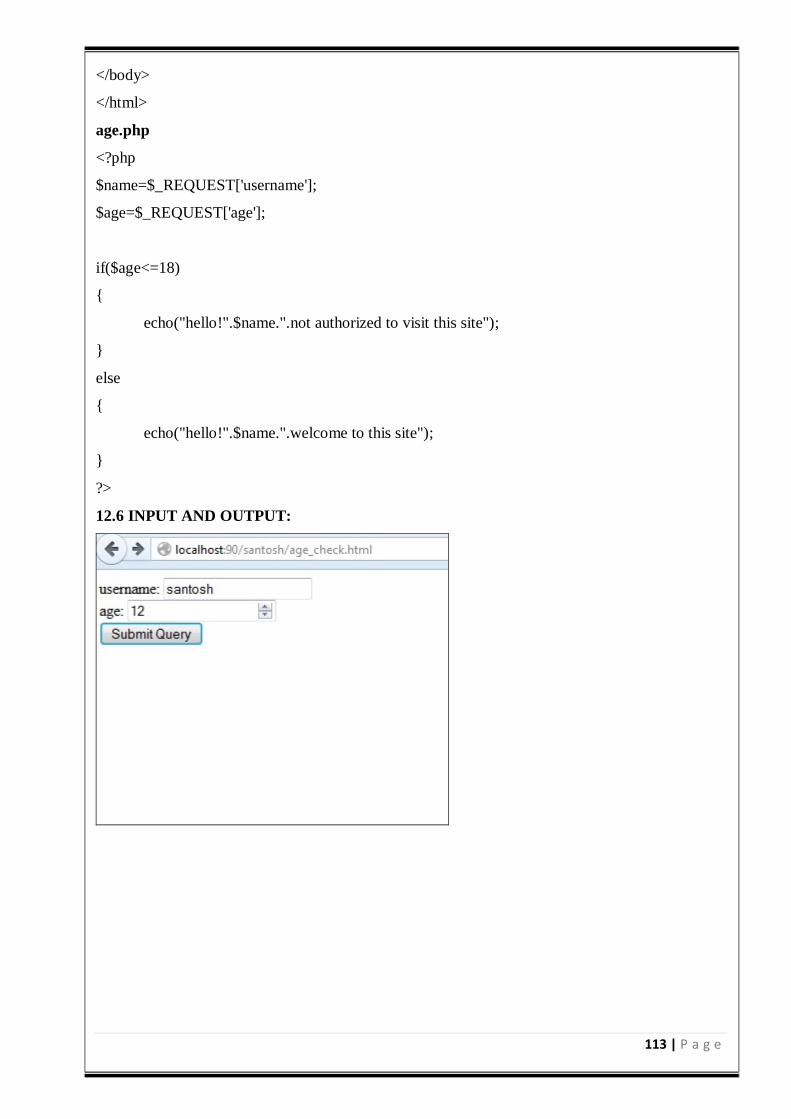
113 | P a g e
</body>
</html>
age.php
<?php
$name=$_REQUEST['username'];
$age=$_REQUEST['age'];
if($age<=18)
echo("hello!".$name.".not authorized to visit this site");
else
echo("hello!".$name.".welcome to this site");
?>
12.6 INPUT AND OUTPUT:
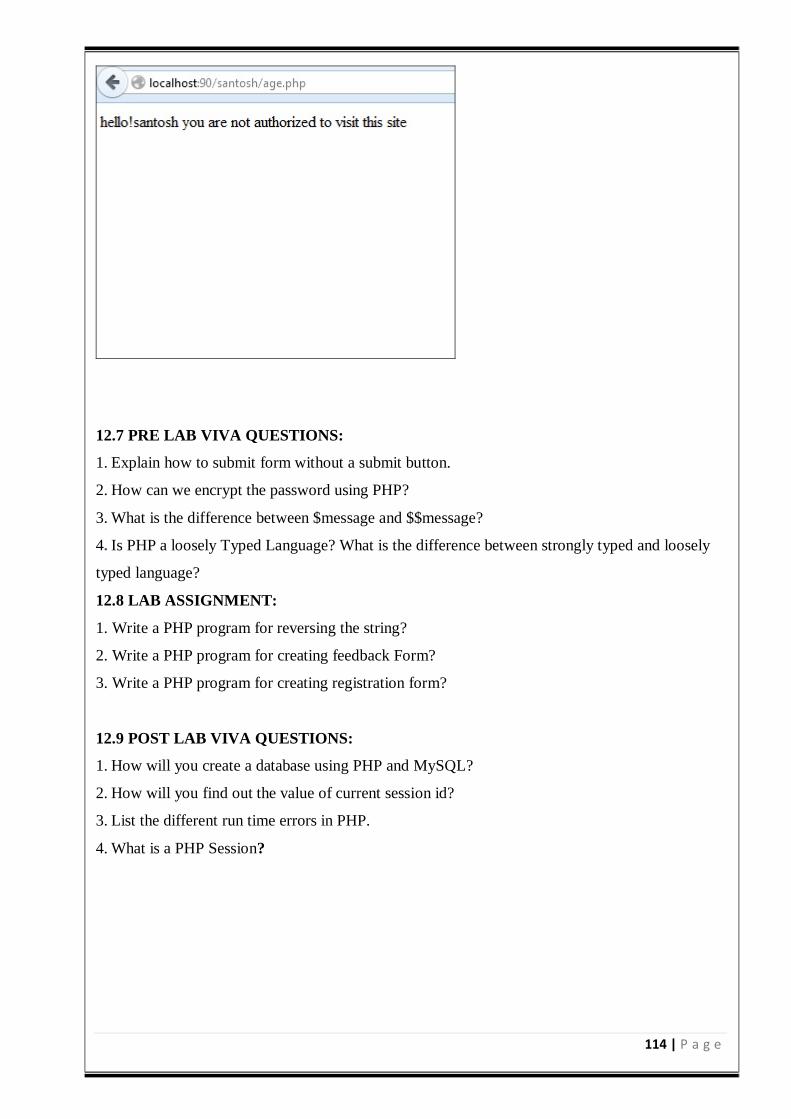
114 | P a g e
12.7 PRE LAB VIVA QUESTIONS:
1. Explain how to submit form without a submit button.
2. How can we encrypt the password using PHP?
3. What is the difference between $message and $$message?
4. Is PHP a loosely Typed Language? What is the difference between strongly typed and loosely
typed language?
12.8 LAB ASSIGNMENT:
1. Write a PHP program for reversing the string?
2. Write a PHP program for creating feedback Form?
3. Write a PHP program for creating registration form?
12.9 POST LAB VIVA QUESTIONS:
1. How will you create a database using PHP and MySQL?
2. How will you find out the value of current session id?
3. List the different run time errors in PHP.
4. What is a PHP Session?