Embed Size (px)
Citation preview
Case Study: Stratified Gas Hydrate Reservoir with Associated Free Gas
Group Project
PETE 680: Horizontal well Technology
Presented By,
Namit Jaiswal,
Adejoke M Ibironke
Objective
1. Gas Hydrates
2. Overview of horizontal well and designer well
3. Case description
4. Results
5. Conclusion
6. Recommendation
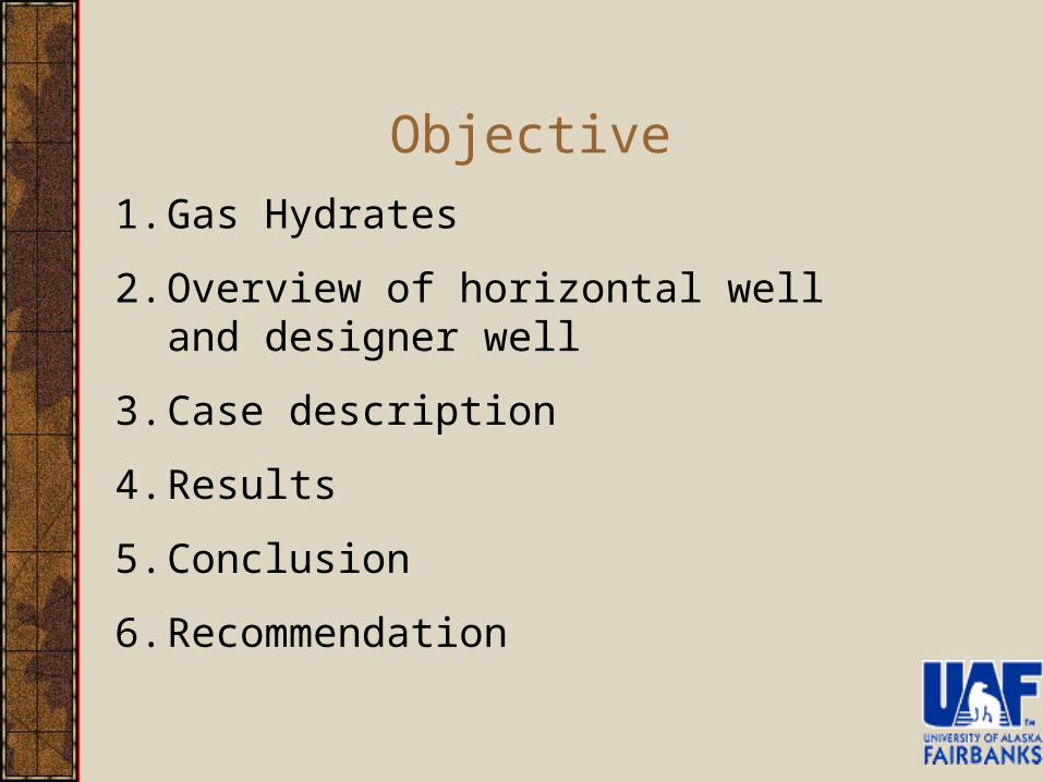
Alaska Methane Hydrate Alaska Methane Hydrate Estimated ResourceEstimated Resource
TARN TREND
FREE GAS?
PBU26%
KRU39%
MPU100%
DIU
EILEEN TREND
44 TCF
60 TCF?
GAS HYDRATE& FREE GAS
GAS HYDRATE
(After Collett, 1993)
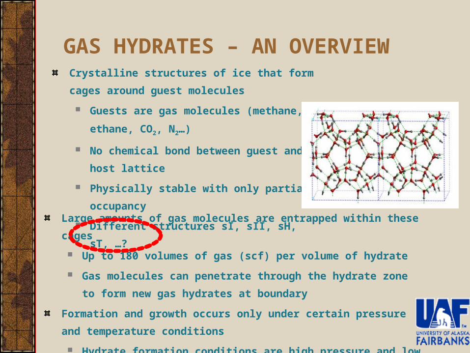
GAS HYDRATES – AN OVERVIEWCrystalline structures of ice that form cages around
guest molecules
Guests are gas molecules (methane, ethane, CO2,
N2…)
No chemical bond between guest and host lattice
Physically stable with only partial occupancy
Different structures sI, sII, sH, sT, …?
Large amounts of gas molecules are entrapped within these cages
Up to 180 volumes of gas (scf) per volume of hydrate
Gas molecules can penetrate through the hydrate zone to form new gas
hydrates at boundary
Formation and growth occurs only under certain pressure and temperature
conditions
Hydrate formation conditions are high pressure and low temperature
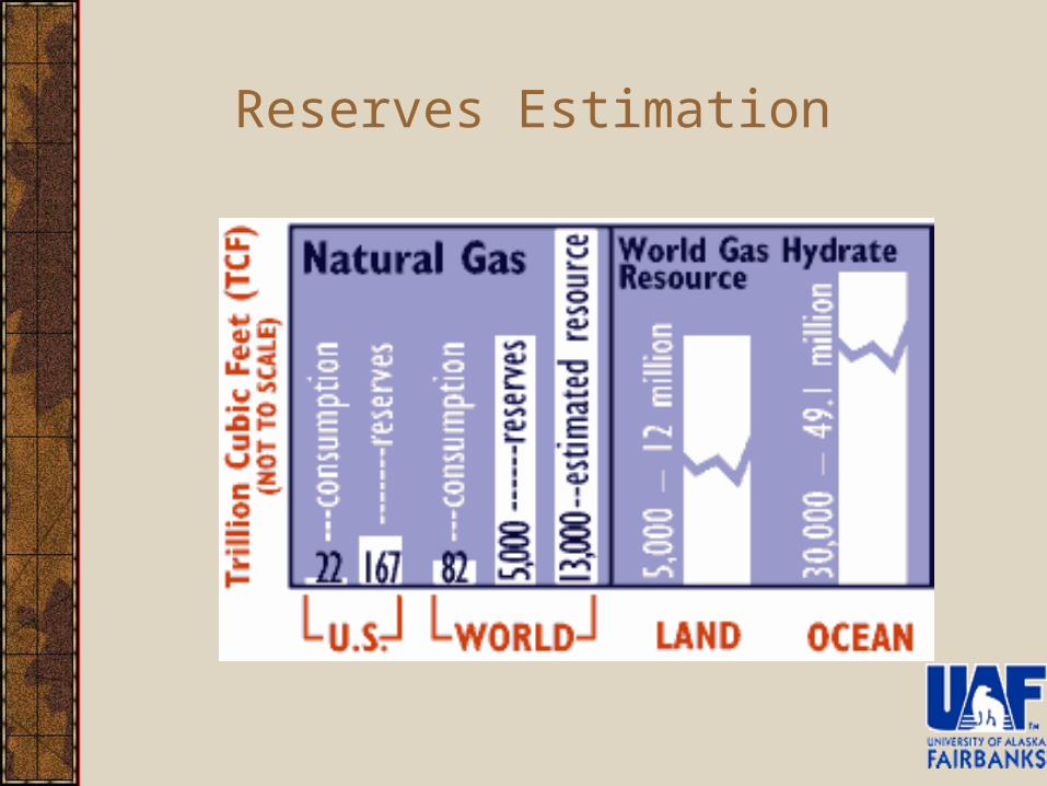
Reserves Estimation
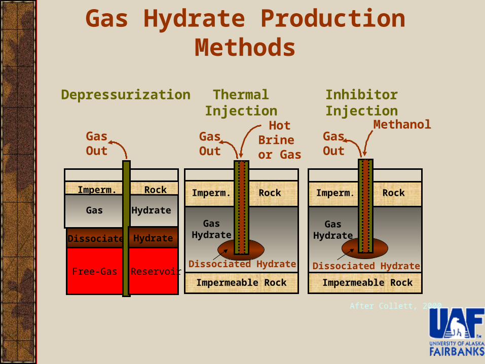
Gas Hydrate Production Methods
Methanol
Dissociated
Thermal Injection
Gas Out
Imperm. Rock
Impermeable Rock
Gas Hydrate
Inhibitor Injection
Gas Out
Imperm. Rock
Impermeable Rock
Depressurization
Free-Gas
Gas Out
Gas Hydrate
Hydrate
Reservoir Dissociated HydrateDissociated Hydrate
Imperm. Rock
Hot Brine or Gas
Gas Hydrate
After Collett, 2000
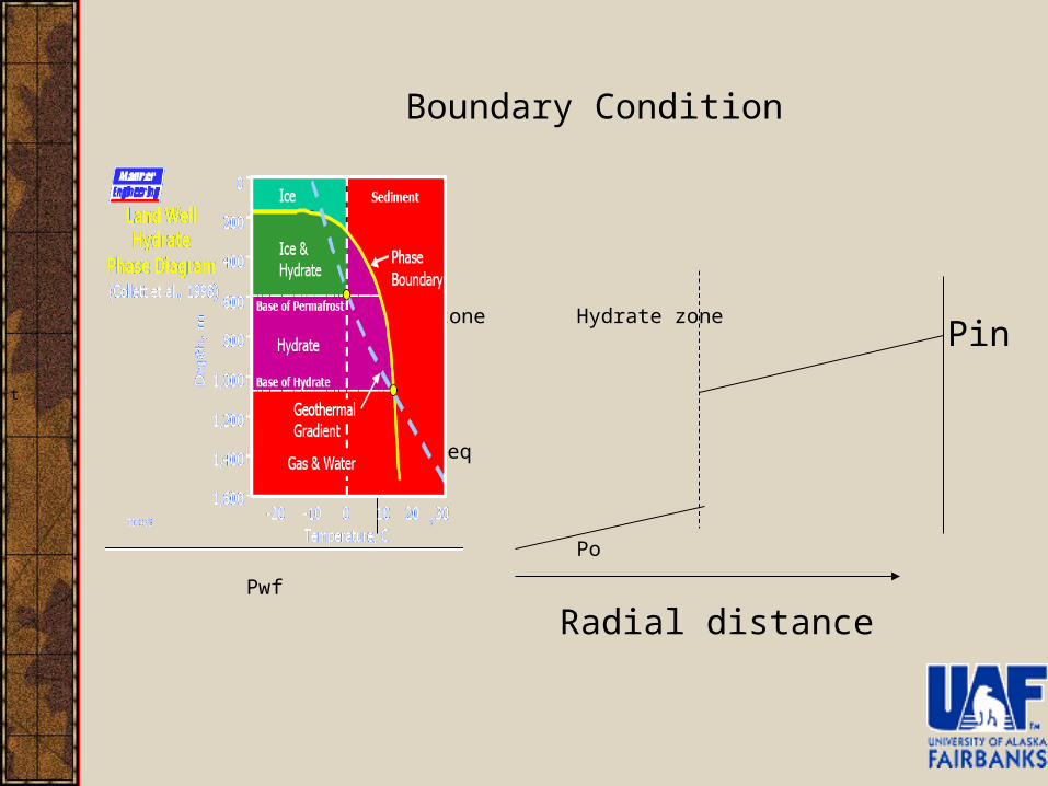
Gas zone Hydrate zone
Pwf
Peq
Po
t
Radial distance
Pin
Boundary Condition
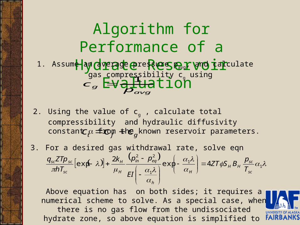
Algorithm for Performance of a Hydrate Reservoir Evaluation
1. Assume an average pressure pavg, and calculate gas compressibility cg
using
avgg p
c1
2. Using the value of cg , calculate total compressibility and hydraulic
diffusivity constant from the known reservoir parameters.
gft ccc
3. For a desired gas withdrawal rate, solve eqn
1
1
1
22
4exp2
expsc
scHH
H
h
eqin
H
H
sc
scsc
T
pBSZT
EI
ppk
hT
ZTpq
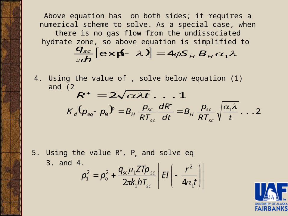
Above equation has on both sides; it requires a numerical scheme to solve. As a special case, when there is no gas flow from the undissociated
hydrate zone, so above equation is simplified to
14exp HH
sc BSh
q
Above equation has on both sides; it requires a numerical scheme to solve. As a special case, when there is no gas flow from the undissociated
hydrate zone, so above equation is simplified to
4. Using the value of , solve below equation (1) and (2
1.......2 tR
2.......10 tRT
pB
dt
dR
RT
pBppK
sc
scH
sc
scH
neqd
5. Using the value R*, Po and solve eq 3. and 4.
t
rEI
hTk
ZTpqpp
sc
scsco
1
2
1
1221 42
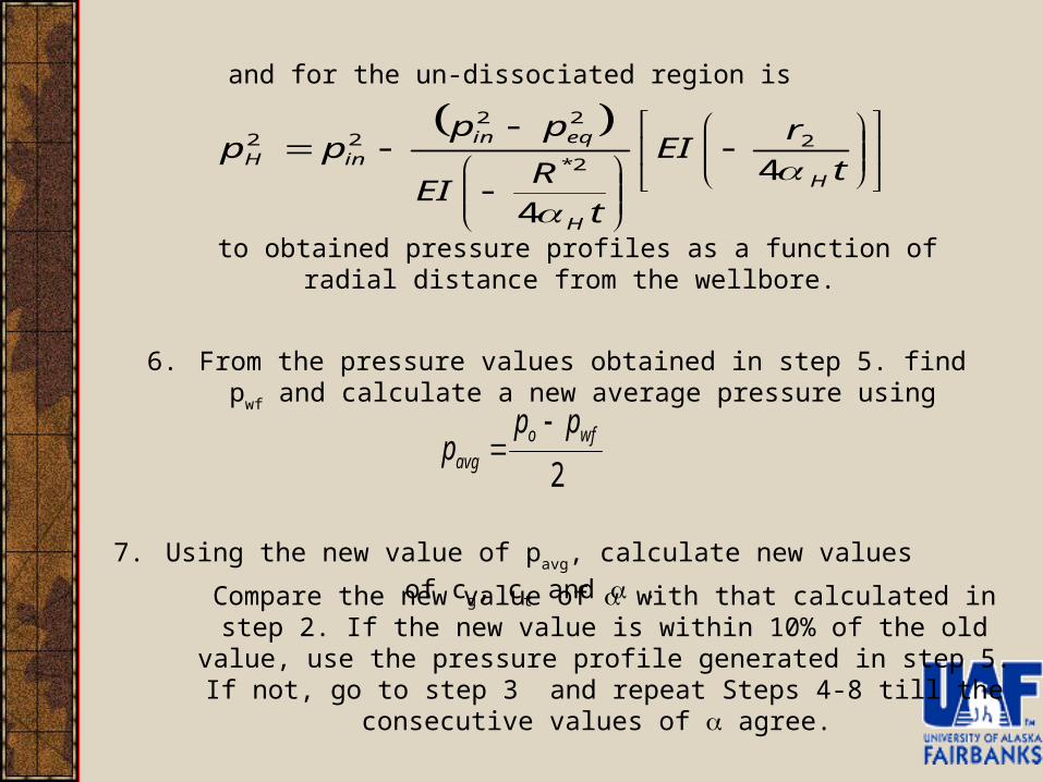
and for the un-dissociated region is
t
rEI
t
REI
pppp
H
H
eqininH
4
4
2
2*
2222
to obtained pressure profiles as a function of radial distance from the wellbore.
6. From the pressure values obtained in step 5. find pwf and calculate a new
average pressure using
2wfo
avg
ppp
7. Using the new value of pavg, calculate new values of cg, ct and .
Compare the new value of with that calculated in step 2. If the new value is within 10% of the old value, use the pressure profile generated in step 5. If not,
go to step 3 and repeat Steps 4-8 till the consecutive values of agree.
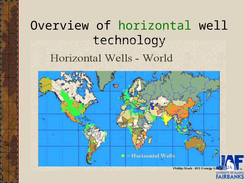
Overview of horizontal well technology
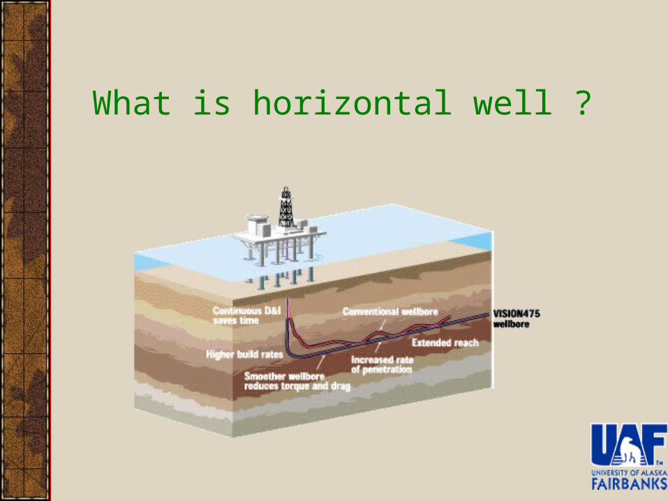
What is horizontal well ?
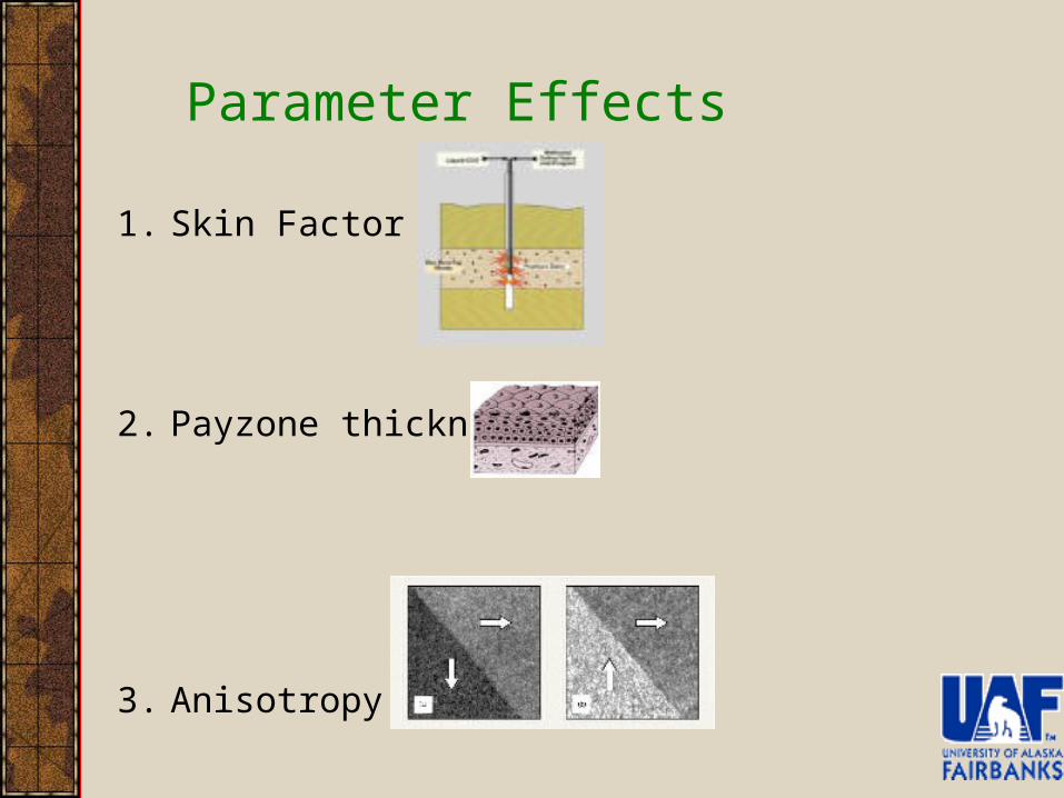
Parameter Effects
1. Skin Factor
2. Payzone thickness
3. Anisotropy
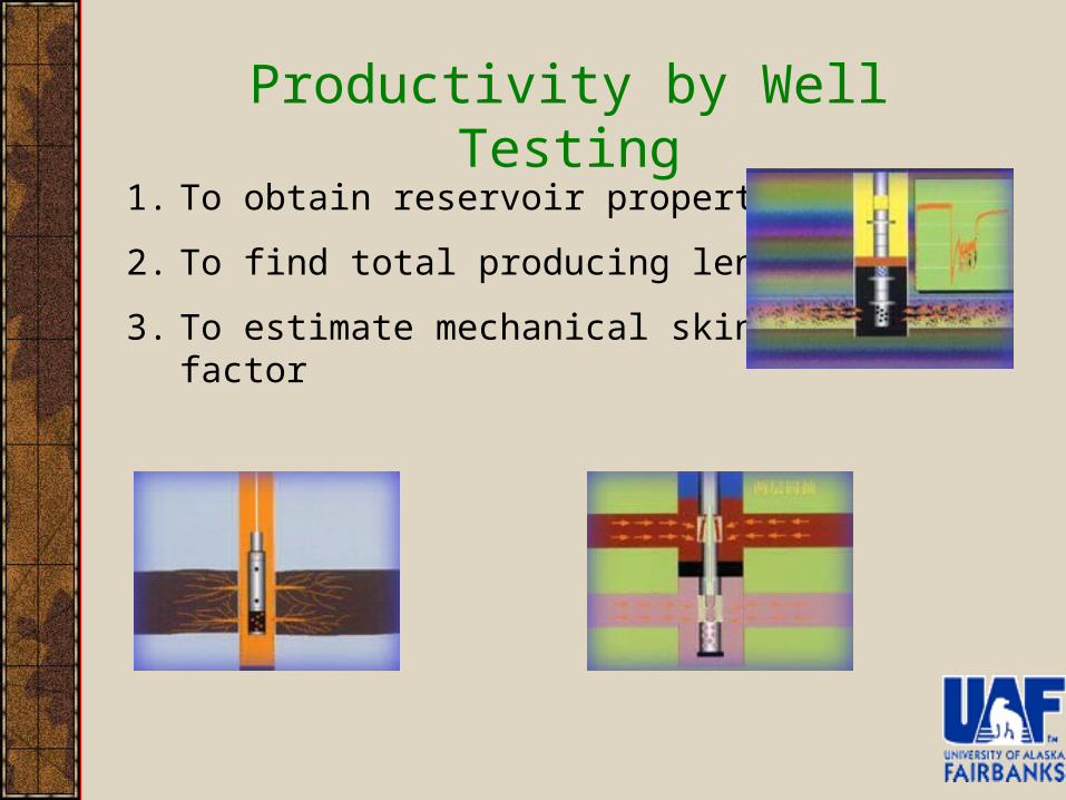
Productivity by Well Testing
1. To obtain reservoir properties
2. To find total producing length
3. To estimate mechanical skin factor
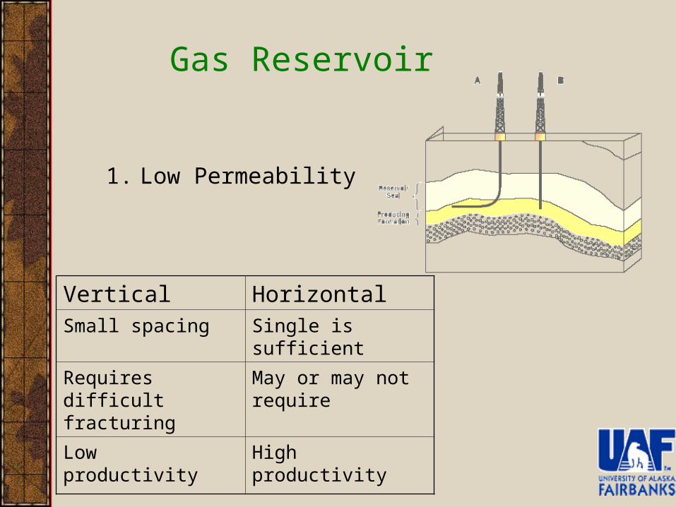
Gas Reservoir
1. Low Permeability
Vertical HorizontalSmall spacing Single is sufficient
Requires difficult fracturing
May or may not require
Low productivity High productivity
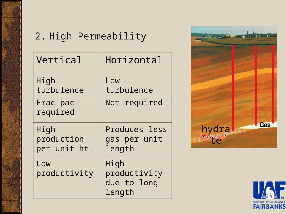
2. High Permeability
Vertical Horizontal
High turbulence Low turbulence
Frac-pac required Not required
High production per unit ht.
Produces less gas per unit length
Low productivity High productivity due to long length
hydrate
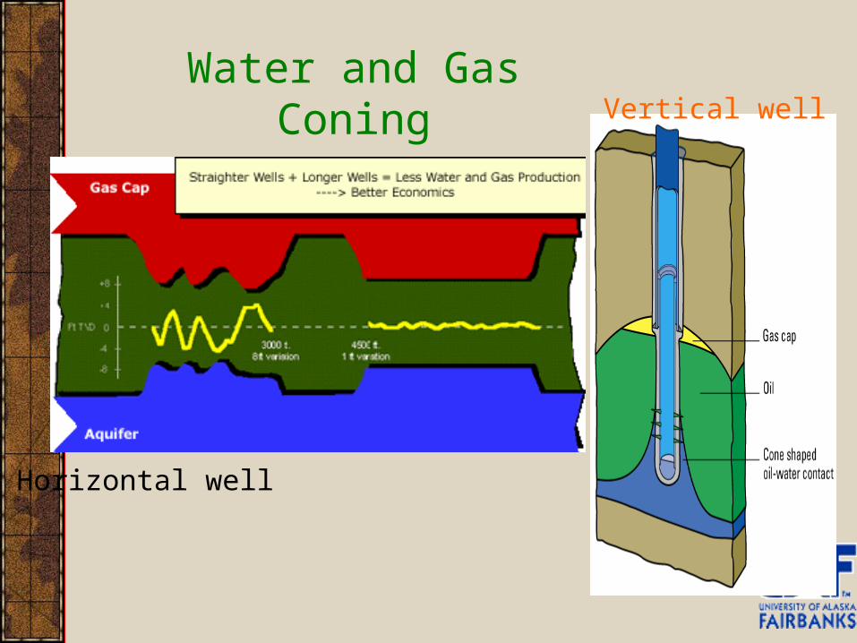
Water and Gas Coning
Horizontal well
Vertical well
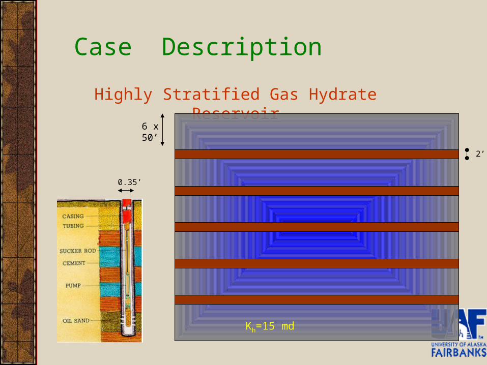
Case Description
Highly Stratified Gas Hydrate Reservoir
0.35’
2’
6 x 50’
Kh=15 md
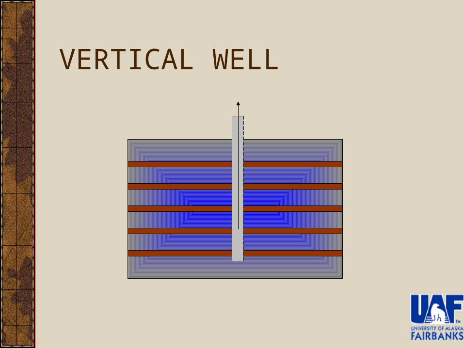
VERTICAL WELL
ASSUMPTIONS FOR VERTICAL WELL RESERVOIR
• Temperature for free gas zone is constant.
• Average viscosity is used for calculation.
• Individual well bore pressure are assumed taken from literature.
• Pressure drop across tubing is negligible.
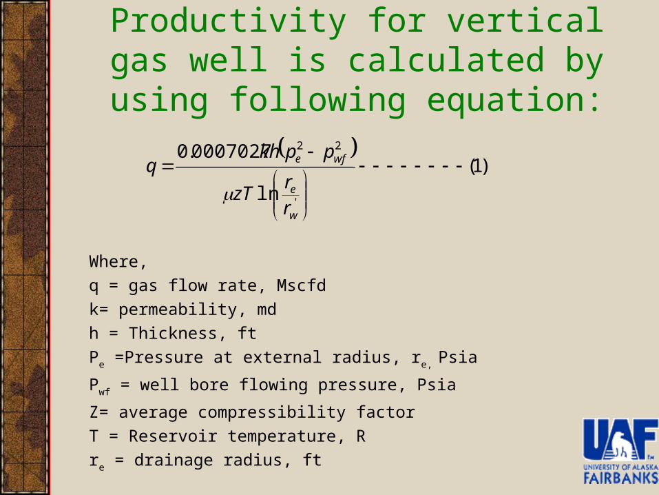
Productivity for vertical gas well is calculated by using following equation:
Where,
q = gas flow rate, Mscfd
k= permeability, md
h = Thickness, ft
Pe =Pressure at external radius, re, Psia
Pwf = well bore flowing pressure, Psia
Z= average compressibility factor
T = Reservoir temperature, R
re = drainage radius, ft
)1(
ln
0007027.0
'
22
w
e
wfe
rr
zT
ppkhq
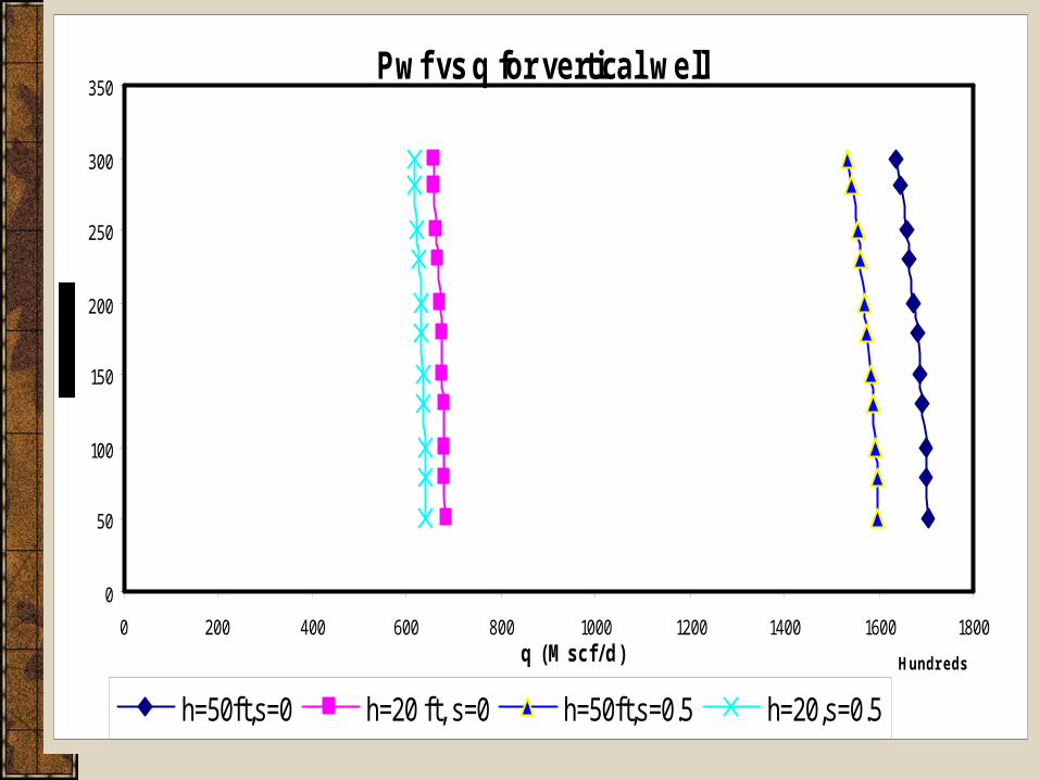
Graph of Pressure Vs production from vertical well
Pwf vs q for vertical well
0
50
100
150
200
250
300
350
0 200 400 600 800 1000 1200 1400 1600 1800
Hundredsq (Mscf/d)
h=50ft,s=0 h=20 ft, s=0 h=50ft,s=0.5 h=20,s=0.5
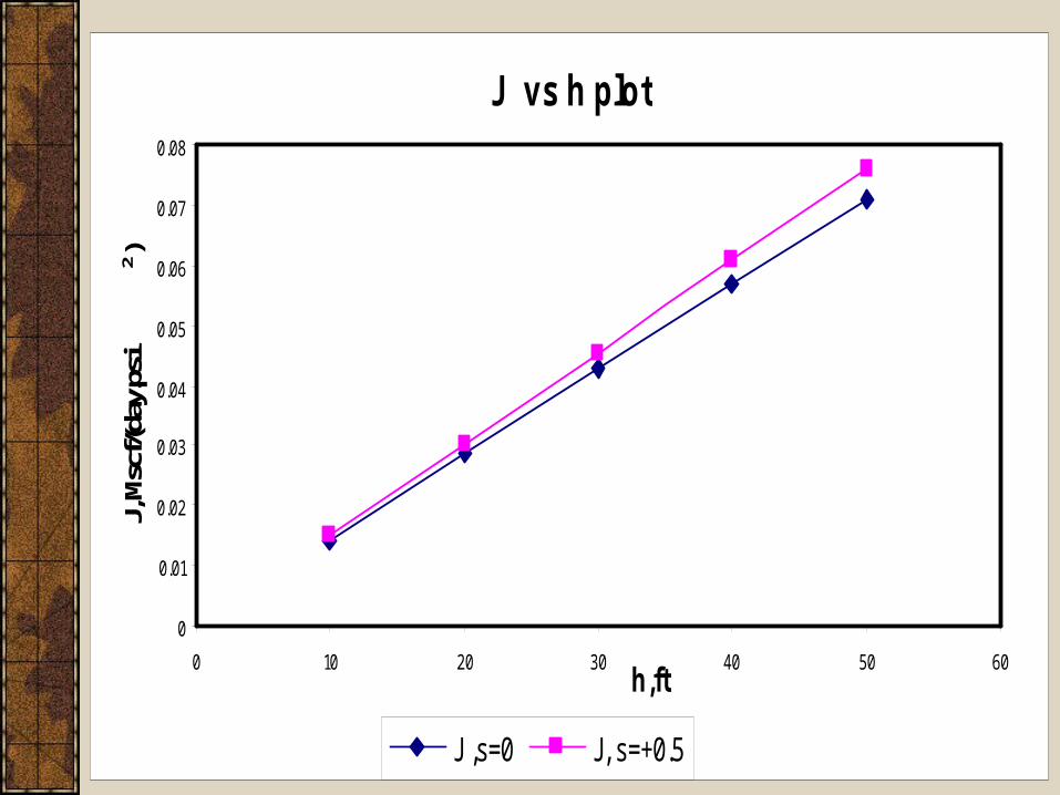
Variation of productivity with payzone thickness.
J vs h plot
0
0.01
0.02
0.03
0.04
0.05
0.06
0.07
0.08
0 10 20 30 40 50 60h,ft
J, M
scf/(
day.
psi
2)
J ,s=0 J, s=+0.5
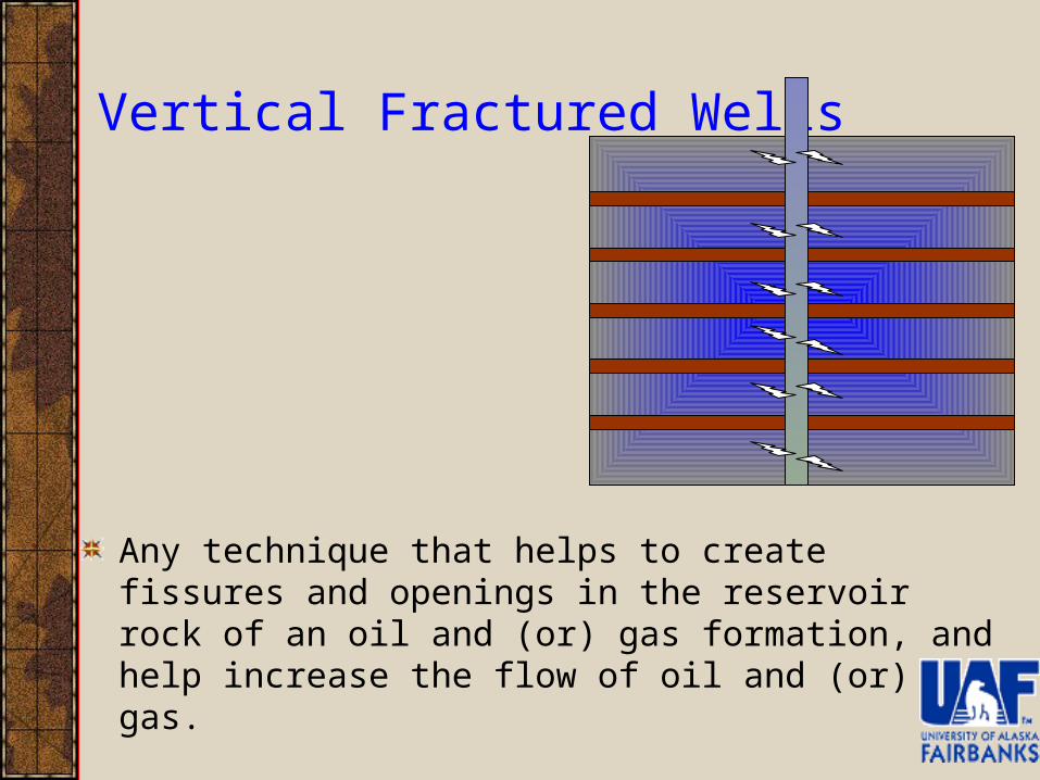
Vertical Fractured Wells
Any technique that helps to create fissures and openings in the reservoir rock of an oil and (or) gas formation, and help increase the flow of oil and (or) gas.
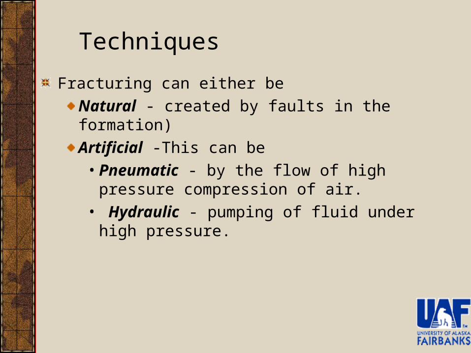
Fracturing can either be
Natural - created by faults in the formation)
Artificial -This can be
• Pneumatic - by the flow of high pressure compression of air.
• Hydraulic - pumping of fluid under high pressure.
Techniques
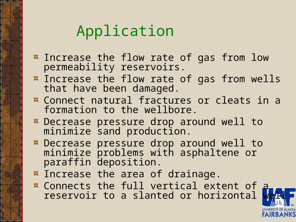
Increase the flow rate of gas from low permeability reservoirs.Increase the flow rate of gas from wells that have been damaged.Connect natural fractures or cleats in a formation to the wellbore.Decrease pressure drop around well to minimize sand production.Decrease pressure drop around well to minimize problems with asphaltene or paraffin deposition.Increase the area of drainage.Connects the full vertical extent of a reservoir to a slanted or horizontal well.
Application

Must have a need to increase the productivity index.
A thick pay zone.
Medium to high pressure.
In-situ stress barriers to minimize vertical height growth.
It will either be a low permeability zone or a zone that has been damaged (high skin factor).
Must have a substantial volume of gas in place.
Candidate Selection
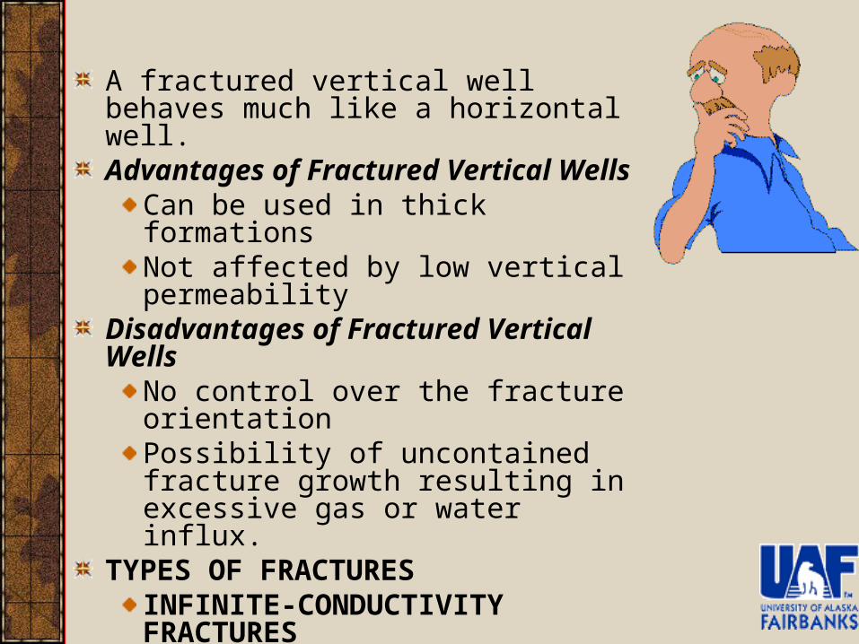
A fractured vertical well behaves much like a horizontal well.Advantages of Fractured Vertical Wells
Can be used in thick formationsNot affected by low vertical permeability
Disadvantages of Fractured Vertical WellsNo control over the fracture orientationPossibility of uncontained fracture growth resulting in excessive gas or water influx.
TYPES OF FRACTURESINFINITE-CONDUCTIVITY FRACTURESUNIFORM FLUX FRACTURESFINITE-CONDUCTIVITY FRACTURES
Assumptions
Drainage volume is box shaped
The well fully penetrates the formation
There is no restricted entry to flow
The production is predominantly stabilized flow for all layers
The effect of non-Darcy flow is ignored
The rock property in each layer is the same
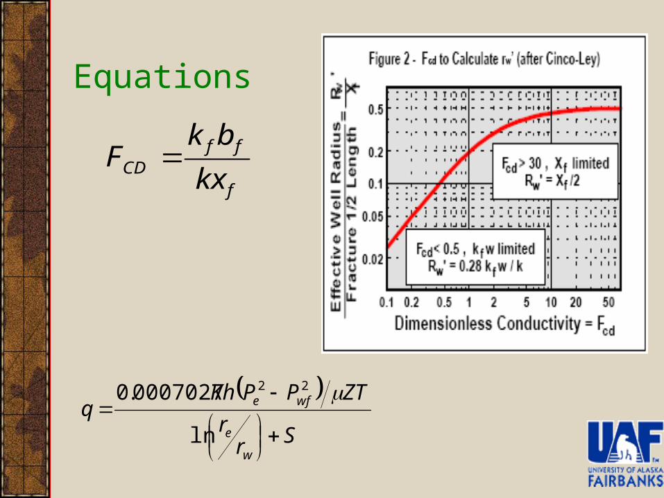
Equations
Sr
r
ZTPPKhq
w
e
wfe
ln
0007027.0 22
f
ffCD kx
bkF
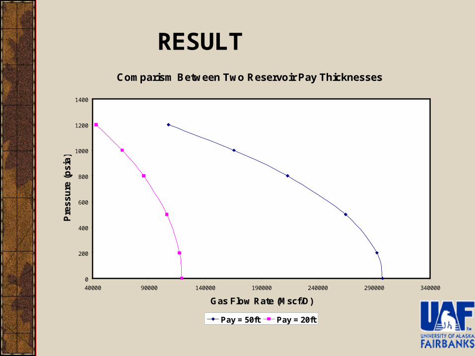
RESULTComparism Between Two Reservoir Pay Thicknesses
0
200
400
600
800
1000
1200
1400
40000 90000 140000 190000 240000 290000 340000
Gas Flow Rate (Mscf/D)
Pre
ss
ure
(p
sia
)
Pay = 50ft Pay = 20ft
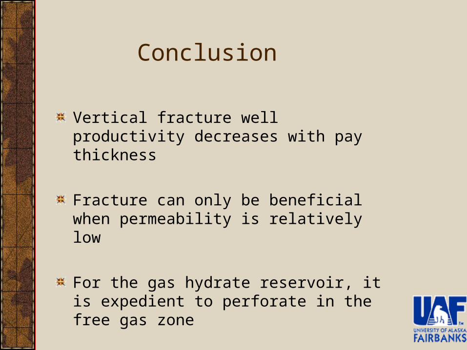
Vertical fracture well productivity decreases with pay thickness
Fracture can only be beneficial when permeability is relatively low
For the gas hydrate reservoir, it is expedient to perforate in the free gas zone
Conclusion
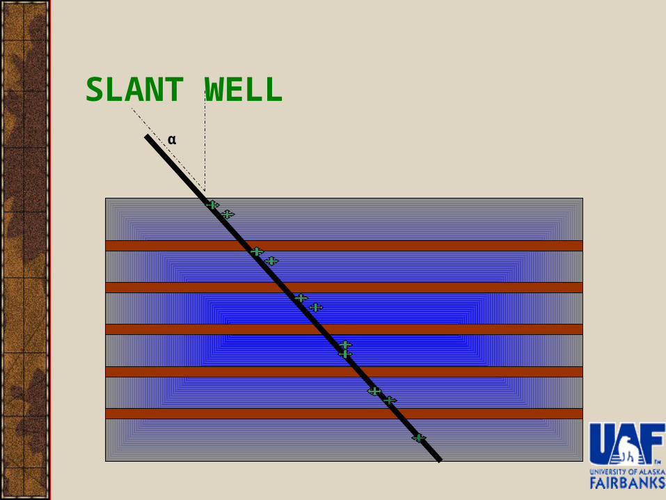
SLANT WELLα
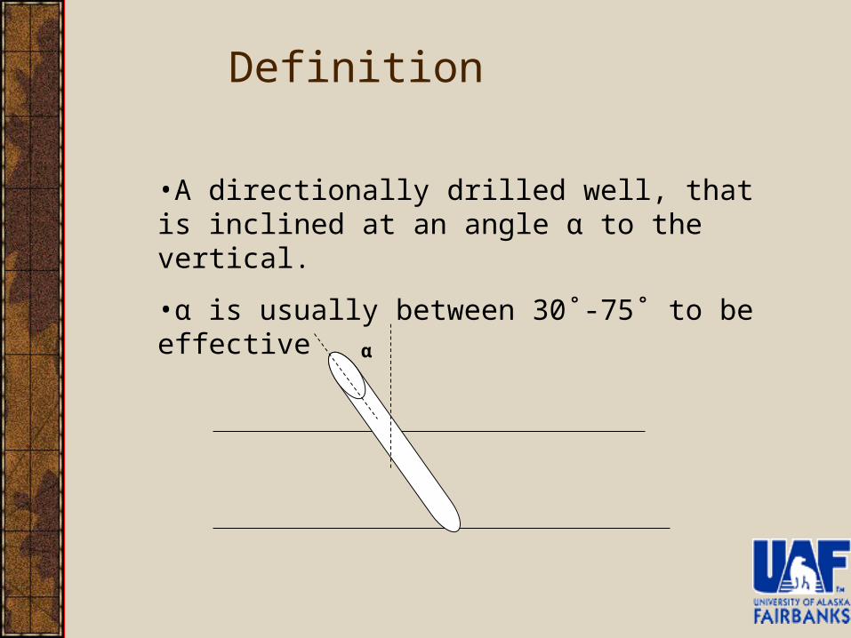
•A directionally drilled well, that is inclined at an angle α to the vertical.
•α is usually between 30˚-75˚ to be effective
Definition
α
Reason for use & Areas of Practical Application
To reduce the cost of drilling several wells from a single platformTo allow extraction of oil/gas from areas unreachable conventionallyIn reservoir with down-dipFor formation with low permeability to gas
The Great Lakes, along the shores of Lake Michigan and HuronIn the Coalbed Methane field of Valencia Canyon in Northern San Juan basin of Colorado.In the Greater Green River Basin of Colorado.
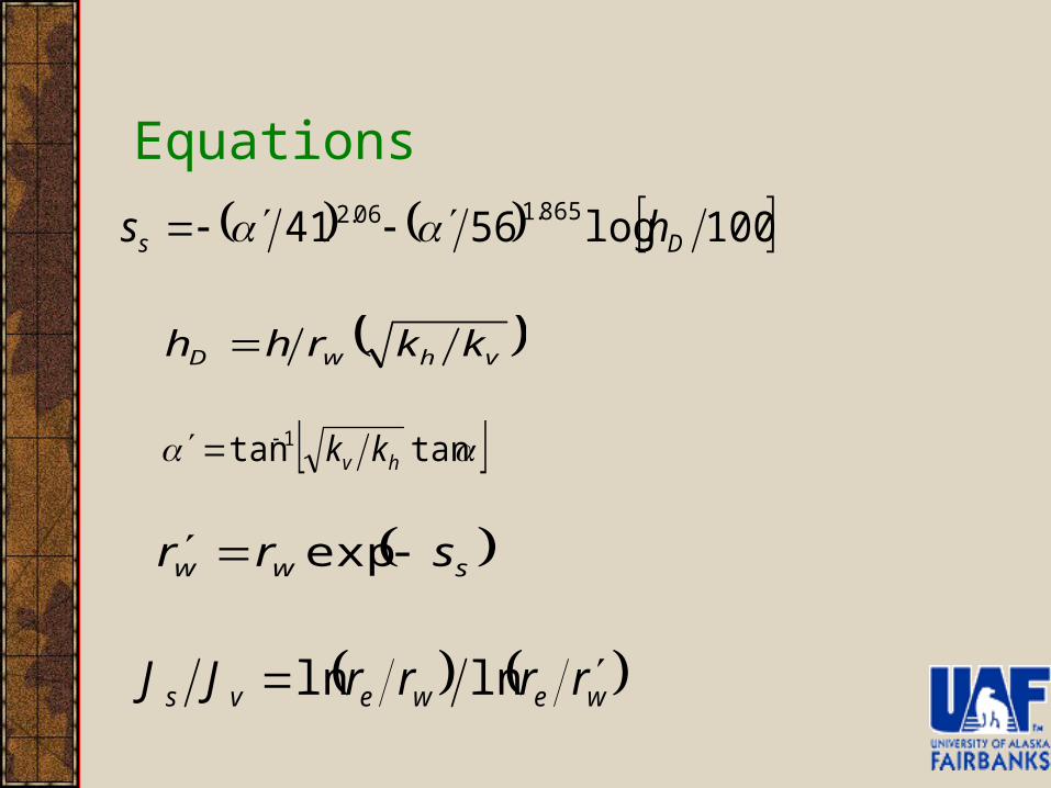
Equations
100log5641 865.106.2Ds hs
vhwD kkrhh
tantan 1hv kk
sww srr exp
wewevs rrrrJJ lnln
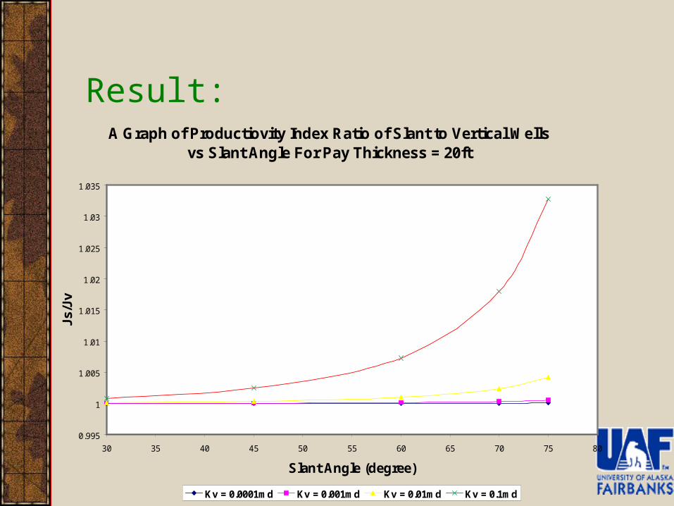
Result:A Graph of Productiovity Index Ratio of Slant to Vertical Wells
vs Slant Angle For Pay Thickness = 20ft
0.995
1
1.005
1.01
1.015
1.02
1.025
1.03
1.035
30 35 40 45 50 55 60 65 70 75 80
Slant Angle (degree)
Js/J
v
Kv = 0.0001md Kv = 0.001md Kv = 0.01md Kv = 0.1md
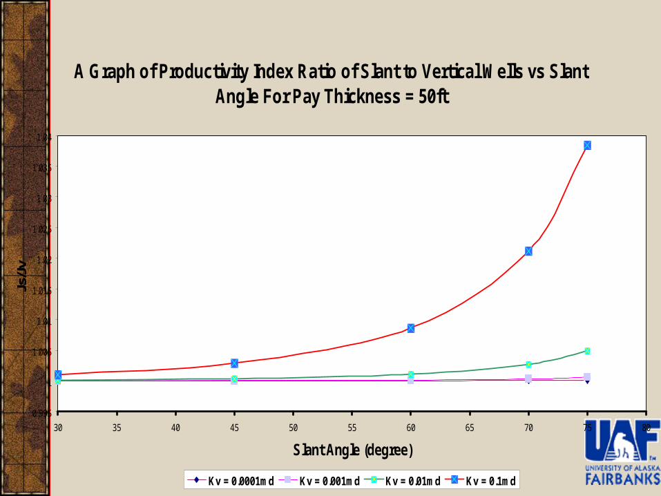
A Graph of Productivity Index Ratio of Slant to Vertical Wells vs Slant Angle For Pay Thickness = 50ft
0.995
1
1.005
1.01
1.015
1.02
1.025
1.03
1.035
1.04
30 35 40 45 50 55 60 65 70 75 80
Slant Angle (degree)
Js/J
v
Kv = 0.0001md Kv = 0.001md Kv = 0.01md Kv = 0.1md
Conclusion
The slant well is highly dependent on the vertical permeability
When the kv is low, then productivity will be low
Gas migrates vertically upward and because the kv is very low the productivity turned out low
The result shows that the slant well has a higher productivity than the vertical well
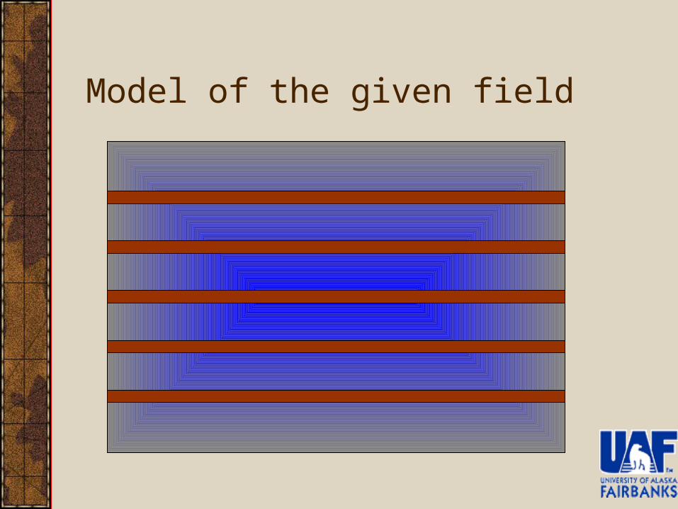
Model of the given field
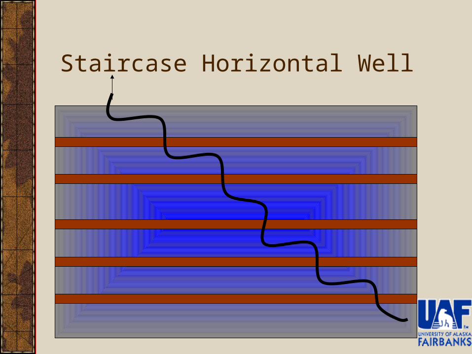
Staircase Horizontal Well
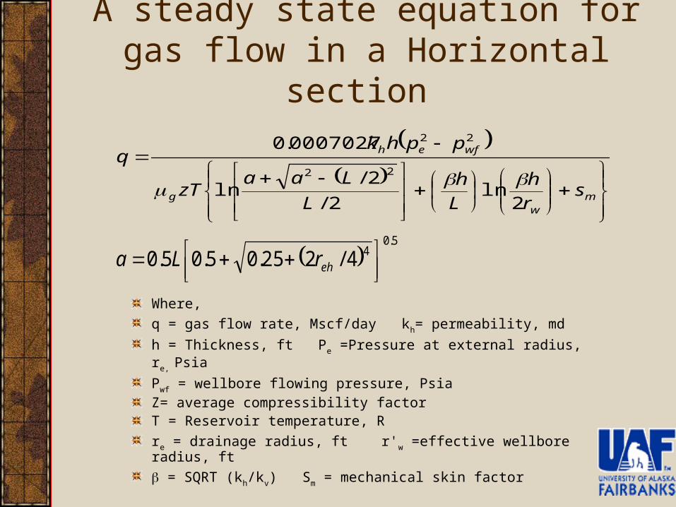
A steady state equation for gas flow in a Horizontal section
Where,
q = gas flow rate, Mscf/day kh= permeability, md
h = Thickness, ft Pe =Pressure at external radius, re, Psia
Pwf = wellbore flowing pressure, PsiaZ= average compressibility factorT = Reservoir temperature, R
re = drainage radius, ft r'w =effective wellbore radius, ft
= SQRT (kh/kv) Sm = mechanical skin factor
5.0
44/225.05.05.0
ehrLa
mw
g
wfeh
sr
h
L
h
L
LaazT
pphkq
2ln
2/
2/ln
0007027.0
22
22
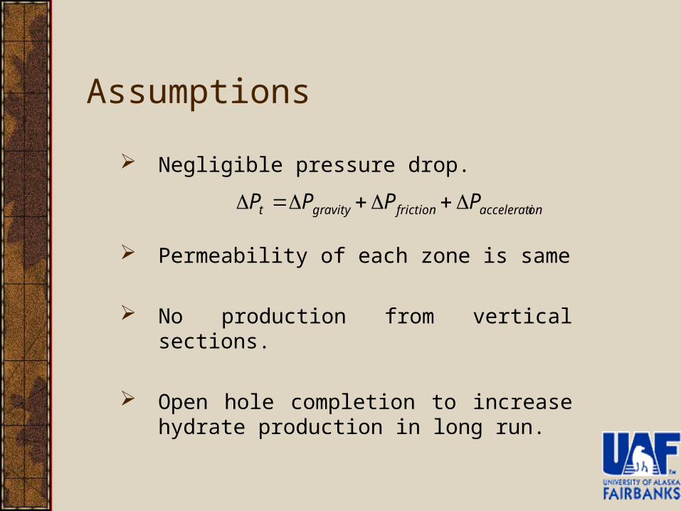
Assumptions
Negligible pressure drop.
Permeability of each zone is same
No production from vertical sections.
Open hole completion to increase hydrate production in long run.
onacceleratifrictiongravityt PPPP
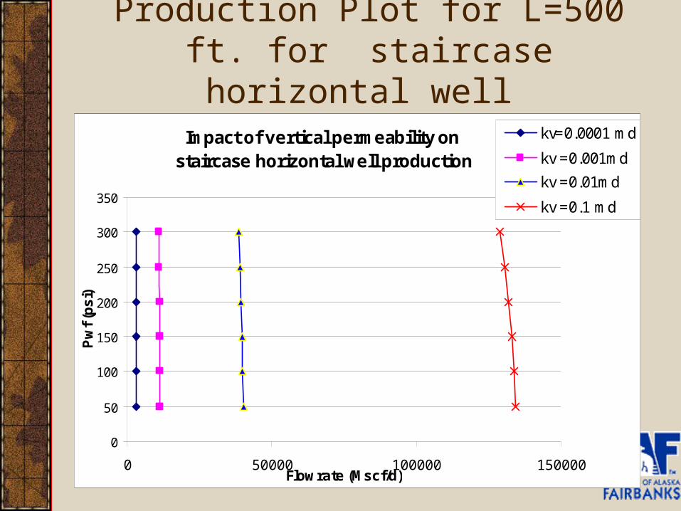
Production Plot for L=500 ft. for staircase horizontal well
Impact of vertical permeability on staircase horizontal well production
0
50
100
150
200
250
300
350
0 50000 100000 150000Flowrate (Mscf/d)
Pw
f (p
si)
kv=0.0001 md
kv =0.001md
kv =0.01md
kv =0.1 md
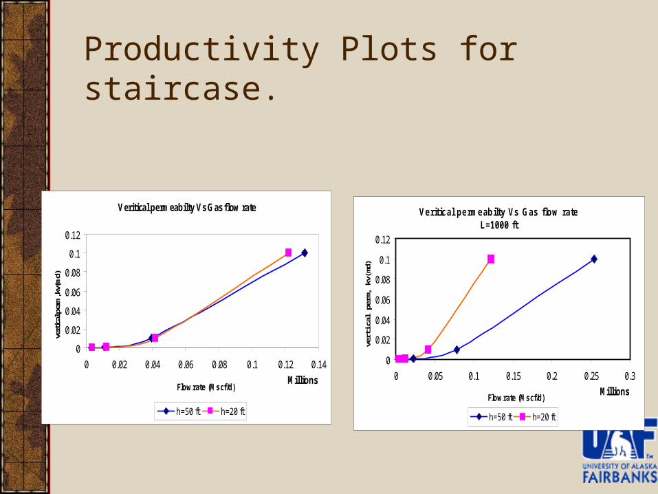
Productivity Plots for staircase.
Veritical permeabilty Vs Gas flow rate
0
0.02
0.04
0.06
0.08
0.1
0.12
0 0.02 0.04 0.06 0.08 0.1 0.12 0.14
MillionsFlowrate (Mscf/d)
verti
cal p
erm
, kv(
md)
h=50 ft h=20 ft
Veritical permeabilty Vs Gas flow rateL=1000 ft
0
0.02
0.04
0.06
0.08
0.1
0.12
0 0.05 0.1 0.15 0.2 0.25 0.3
MillionsFlowrate (Mscf/d)
verti
cal p
erm
, kv(
md)
h=50 ft h=20 ft
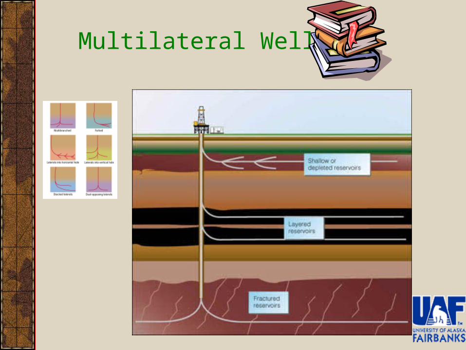
Multilateral Wells
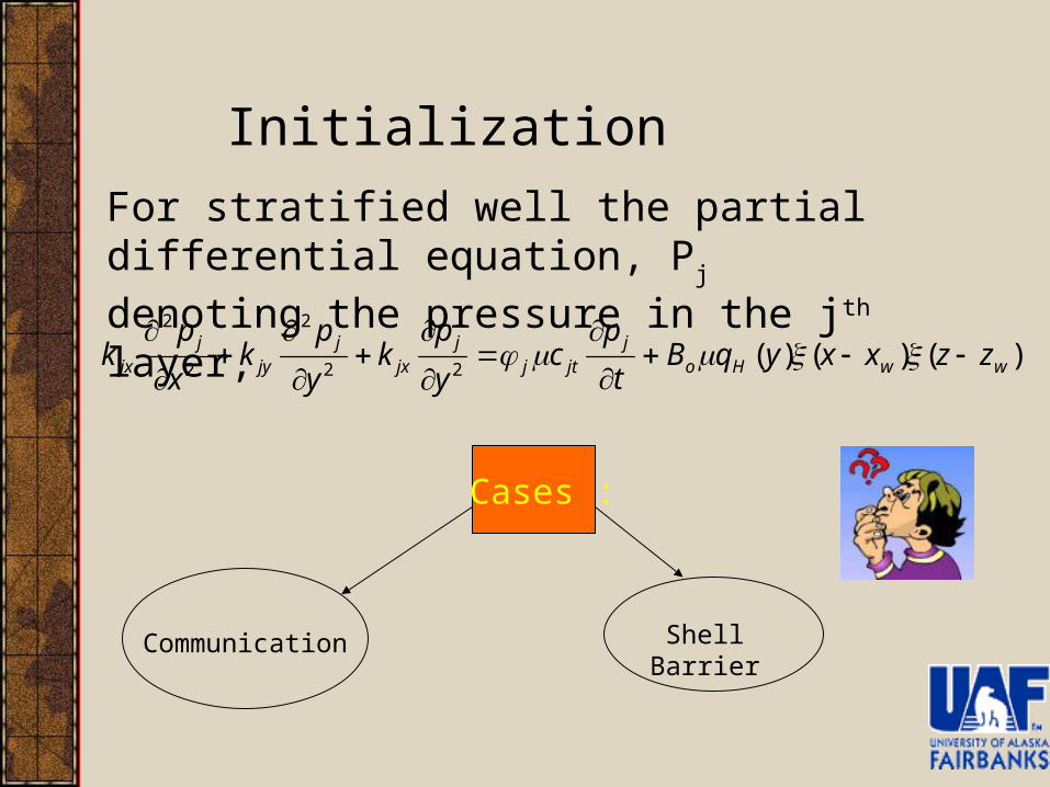
Initialization
For stratified well the partial differential equation, Pj denoting the pressure in the jth layer,
)()()(22
2
2
2
wwHoj
jtjj
jxj
jyj
jx zzxxyqBt
pc
y
pk
y
pk
x
pk
Cases :
Communication Shell Barrier
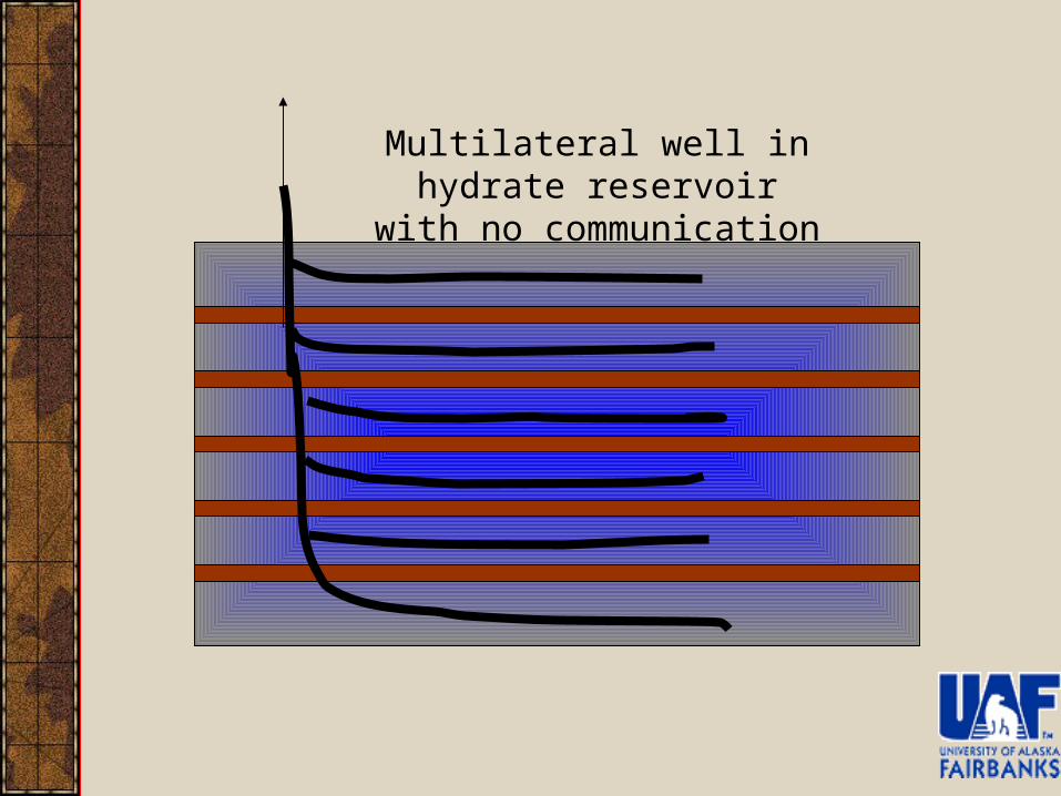
Multilateral well in hydrate reservoir with no communication
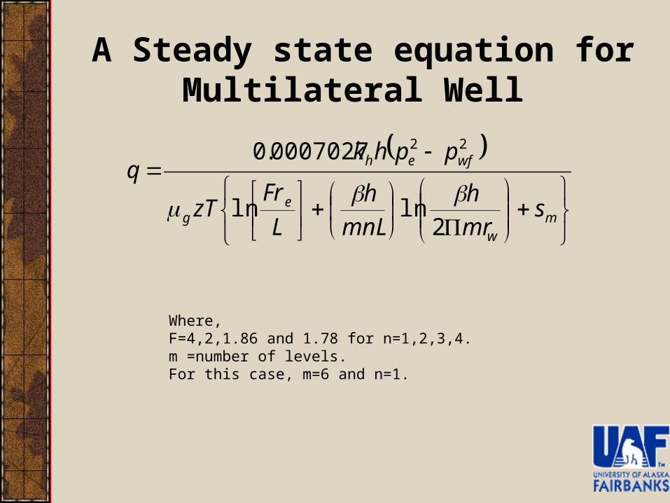
Where,F=4,2,1.86 and 1.78 for n=1,2,3,4.m =number of levels.For this case, m=6 and n=1.
A Steady state equation for Multilateral Well
mw
eg
wfeh
smr
h
mnL
h
L
FrzT
pphkq
2lnln
0007027.0 22
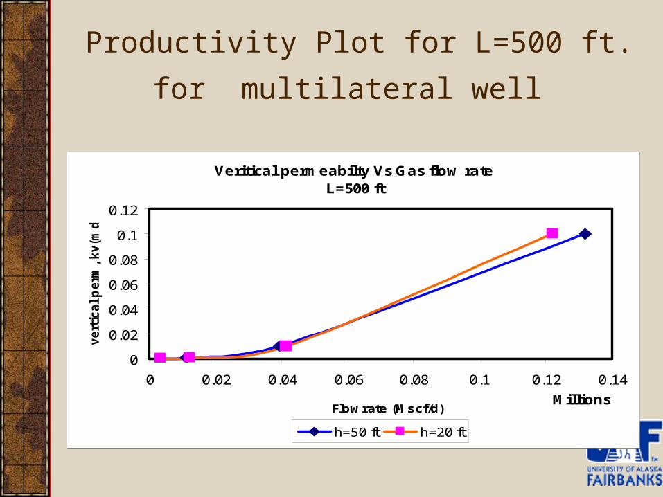
Productivity Plot for L=500 ft. for
multilateral well
Veritical permeabilty Vs Gas flow rateL=500 ft
0
0.02
0.04
0.06
0.08
0.1
0.12
0 0.02 0.04 0.06 0.08 0.1 0.12 0.14
MillionsFlowrate (Mscf/d)
vert
ical p
erm
, kv(m
d)
h=50 ft h=20 ft
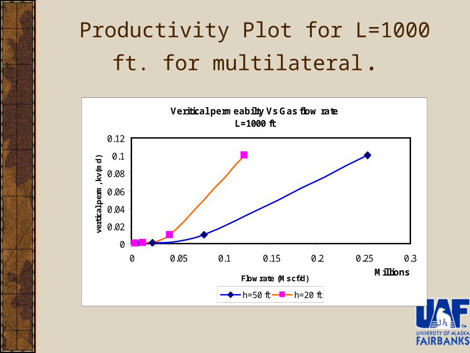
Productivity Plot for L=1000 ft. for
multilateral.
Veritical permeabilty Vs Gas flow rateL=1000 ft
0
0.02
0.04
0.06
0.08
0.1
0.12
0 0.05 0.1 0.15 0.2 0.25 0.3
MillionsFlowrate (Mscf/d)
vert
ical
per
m, k
v(m
d)
h=50 ft h=20 ft
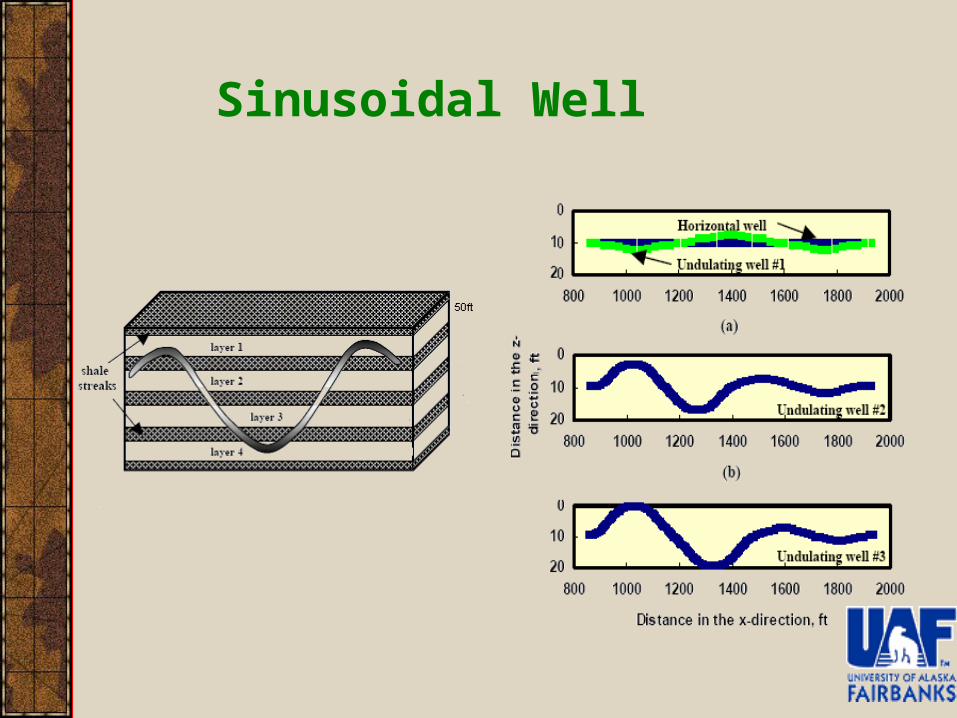
Sinusoidal Well
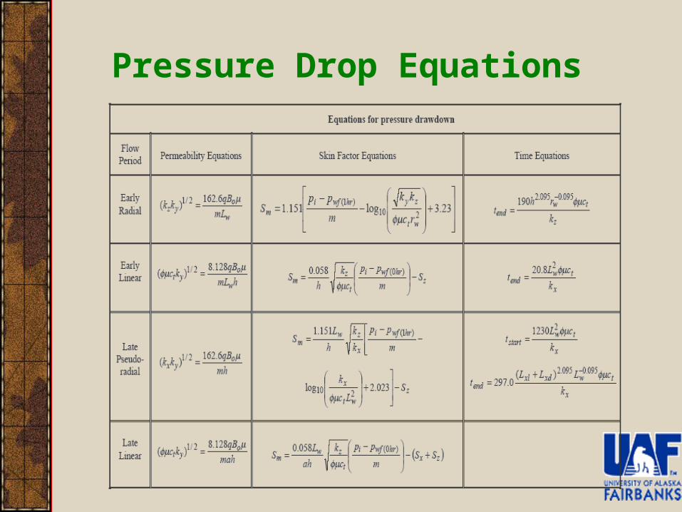
Pressure Drop Equations
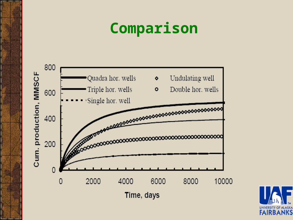
Comparison
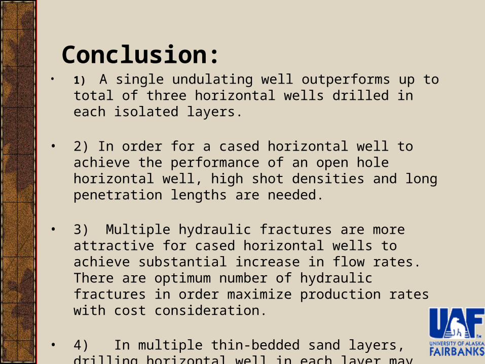
• 1) A single undulating well outperforms up to total of three horizontal wells drilled in each isolated layers.
• 2) In order for a cased horizontal well to achieve the performance of an open hole horizontal well, high shot densities and long penetration lengths are needed.
• 3) Multiple hydraulic fractures are more attractive for cased horizontal wells to achieve substantial increase in flow rates. There are optimum number of hydraulic fractures in order maximize production rates with cost consideration.
• 4) In multiple thin-bedded sand layers, drilling horizontal well in each layer may not be feasible. Hydraulic fracturing of horizontal well to reach out to remaining sand layer may not easily achievable either. In such reservoir, drilling an undulating well seems to be more suitable completion technique.
Conclusion:
Conclusion
Recommendation
Productivity per unit length is highest in vertical well\
Overall productivity is highest for multilateral well
Incorporating in some way to productivity equation

Namit
![[XLS]hsbte.org.inhsbte.org.in/pdf/Total UMC case Decision Sr.No. 1-1206.xlsx · Web viewDevender S/O Sh. Ishwar Singh, VPO- Dhigal Beri, Jhajjar 0806707014 Namit Yadav S/O Sh. Dayanand](https://img.dokumen.tips/doc/110x75/5aa40fa67f8b9a2f048bb866/xlshsbteorg-umc-case-decision-srno-1-1206xlsxweb-viewdevender-so-sh-ishwar.jpg)