Embed Size (px)
Citation preview

1
CASE STUDY:
FIBER LASER CUTTING OF 3D STAMPINGS,
DEEP DRAW AND METAL SPINNING PARTS
Brian Petersen – Kryton Engineered Metals
Robert Kloczkowski – Rofin-Sinar, Inc
ABSTRACT
The subject of this paper examines a case study of the fiber laser cutting of three-dimensional
parts, specifically; parts produced by stamping and deep draw presses as well as metal
spinning lathes. Because the raw material is formed, pressed or stretched during the shaping
of the part, the cutting of accurate holes, slots and flanges mandates a secondary operation.
During this process, it is important that cutting or drilling is completed without the risk of
deforming the part.
Typically, sheet metal fabricators and manufacturers perform this secondary operation by
utilizing one or more of the following methods: custom drilling fixtures, machining equipment,
custom dies, hand tools, 5-axis water-jet or laser systems.
The latter method has proven to provide the greatest benefits, especially with the recent
development of 5 and 6-axis workstations utilizing new high power fiber laser technology. This
new technology offers the reliability and efficiency of solid state electronics as well as the
flexibility of fiber optic beam delivery to the cutting head. In addition, other technologies have
enhanced multi-axis fiber laser workstations including precision linear drives, powerful control
and CADCAM software systems.
This case study will explore the machine design, processing benefits, applications and ROI of
a fiber laser cutting system that is processing three dimensional parts at Kryton Engineered
Metals, Cedar Falls, Iowa. The company recently installed a Rofin-Sinar, Inc. UW505 2000
Watt 5-Axis Fiber Laser Workstation.
Introduction: Kryton Engineered Metals
o Applications, Process Challenges and Descriptions
UW505 Workstation Design
o 5-Axis Drives, Fiber Laser and Beam Delivery
o Controls and CENIT 3D CADCAM Software
Application Examples
o Description of Parts
o Performance Improvements and Cost Reductions
ROI and Project Payback
Conclusion
2
INTRODUCTION
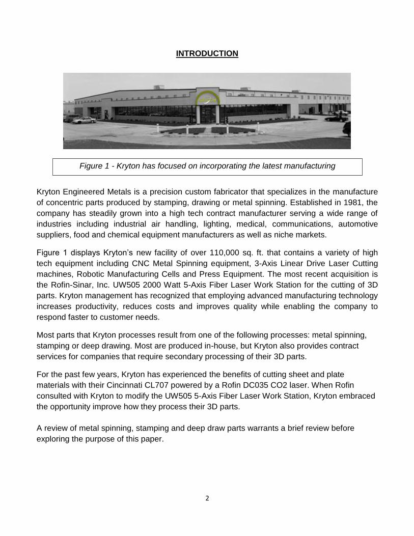
Kryton Engineered Metals is a precision custom fabricator that specializes in the manufacture
of concentric parts produced by stamping, drawing or metal spinning. Established in 1981, the
company has steadily grown into a high tech contract manufacturer serving a wide range of
industries including industrial air handling, lighting, medical, communications, automotive
suppliers, food and chemical equipment manufacturers as well as niche markets.
Figure 1 displays Kryton’s new facility of over 110,000 sq. ft. that contains a variety of high
tech equipment including CNC Metal Spinning equipment, 3-Axis Linear Drive Laser Cutting
machines, Robotic Manufacturing Cells and Press Equipment. The most recent acquisition is
the Rofin-Sinar, Inc. UW505 2000 Watt 5-Axis Fiber Laser Work Station for the cutting of 3D
parts. Kryton management has recognized that employing advanced manufacturing technology
increases productivity, reduces costs and improves quality while enabling the company to
respond faster to customer needs.
Most parts that Kryton processes result from one of the following processes: metal spinning,
stamping or deep drawing. Most are produced in-house, but Kryton also provides contract
services for companies that require secondary processing of their 3D parts.
For the past few years, Kryton has experienced the benefits of cutting sheet and plate
materials with their Cincinnati CL707 powered by a Rofin DC035 CO2 laser. When Rofin
consulted with Kryton to modify the UW505 5-Axis Fiber Laser Work Station, Kryton embraced
the opportunity improve how they process their 3D parts.
A review of metal spinning, stamping and deep draw parts warrants a brief review before
exploring the purpose of this paper.
Figure 1 - Kryton has focused on incorporating the latest manufacturing
technology.
3
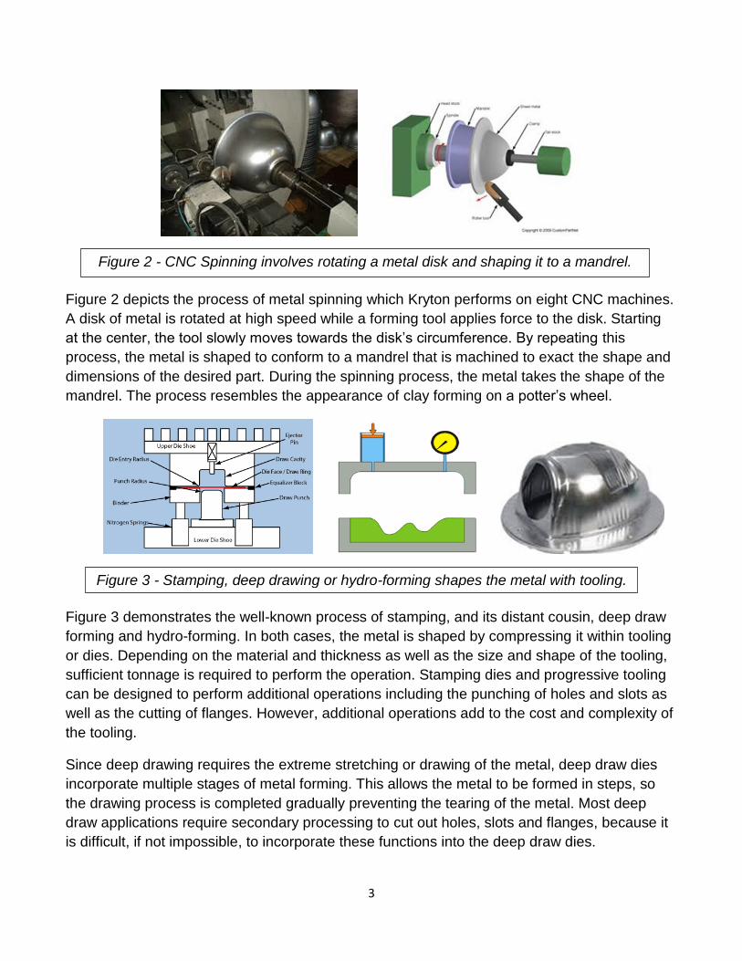
Figure 2 depicts the process of metal spinning which Kryton performs on eight CNC machines.
A disk of metal is rotated at high speed while a forming tool applies force to the disk. Starting
at the center, the tool slowly moves towards the disk’s circumference. By repeating this
process, the metal is shaped to conform to a mandrel that is machined to exact the shape and
dimensions of the desired part. During the spinning process, the metal takes the shape of the
mandrel. The process resembles the appearance of clay forming on a potter’s wheel.
Figure 3 demonstrates the well-known process of stamping, and its distant cousin, deep draw
forming and hydro-forming. In both cases, the metal is shaped by compressing it within tooling
or dies. Depending on the material and thickness as well as the size and shape of the tooling,
sufficient tonnage is required to perform the operation. Stamping dies and progressive tooling
can be designed to perform additional operations including the punching of holes and slots as
well as the cutting of flanges. However, additional operations add to the cost and complexity of
the tooling.
Since deep drawing requires the extreme stretching or drawing of the metal, deep draw dies
incorporate multiple stages of metal forming. This allows the metal to be formed in steps, so
the drawing process is completed gradually preventing the tearing of the metal. Most deep
draw applications require secondary processing to cut out holes, slots and flanges, because it
is difficult, if not impossible, to incorporate these functions into the deep draw dies.
Figure 2 - CNC Spinning involves rotating a metal disk and shaping it to a mandrel.
Figure 3 - Stamping, deep drawing or hydro-forming shapes the metal with tooling.

4
KRYTON APPLICATIONS:
Kryton processes a wide range of materials including steel, stainless steel, aluminum, copper,
brass and other specialty alloys. Raw material thicknesses range from .010” up to .500” and
part diameters from 3” to 120”. Most customer parts mandate dimensional and hole accuracies
of + .010” or greater; however, some jobs require over 50% tighter tolerances. Lot sizes are
generally small to medium volumes, thereby requiring fast setup and changeover capability.
Since each 3D part represents a costly investment including material costs, labor and
equipment burden rates, it is critical that the secondary processing is achieved without
deformation of the part that would result in scrapped parts. Therefore, the cutting of holes,
slots and flanges requires accuracy and edge quality while maintaining the part shape integrity.
The majority of Kryton’s parts exhibit the following characteristics:
Material: steel, stainless steel, aluminum, brass, copper
Thickness: 0.030” to .250”
Diameter: 6.0” to 40.0”
Accuracy: + .005” or greater
Lot size: prototype to 2000 pieces:
Primary Part Shapes: hemispheres, cones, rings, dishes, bowls
Secondary Part Features:
Holes: 0.135” to 5” diameters
Slot cutouts: 0.500” to 5” lengths
Flange cuts: straight, repetitive, irregular
Manufacturing Steps:
2D laser cutting of material into disks
Metal spinning or deep draw press
Drilling holes
Punching of holes, slots and notches
Flange cutting
De-burring
Other operations

5
Figure 4 reveals a large collection of typical parts, most of which are concentric, because they
are produced on CNC metal spinning lathes or formed in stamping dies or deep draw tooling.
During the processing of the material, the original material thickness can be reduced
dramatically as the metal is stretched and formed. Typical part shapes include hemispheres,
cones, rings, dishes, bowls and other concentric shapes.
KRYTON PROCESS CHALLENGES AND DESCRIPTIONS:
Kryton’s challenge in processing 3D parts always needed to answer the question:
How to efficiently and accurately position the part, and then, perform a precision, high quality
cut in a thin-walled metal alloy without deforming the edge or contour of the 3-dimensional
surface?
The question usually required an answer that involved several complex steps:
1. Making a fixture that conforms to the part geometry.
2. Securing the part in a fixture that guarantees repeatable positioning.
3. Accurately locating the position of holes, cutouts and flanges according to the 3D
part print.
4. Preparing and utilizing a machine tool, die, punch, drill, saw or hand tool to process
the part.
5. Processing the part without deforming the part.
6. De-burring or rework to insure high quality edge condition and contour.
7. Repeating the process in the future when customer orders more parts.
8. Modifying the process 1-7 when design changes occur in the part.
For Kryton, the steps 1 through 7 represented a labor and/or equipment components, each of
which had costly burden rates. More importantly, each step added handling to the overall
manufacturing time of the part thereby limiting production throughput.
Figure 4 - Kryton’s 3D parts are typically concentric: cones, rings, dishes and bowls.

6
Kryton addressed the processing challenges by developing part fixtures, custom die punches
and drilling fixtures. Utilizing CNC lathes and machining equipment represented additional
solutions. Often manual operations using hand tools were employed to solve hard to access
material removal or perform de-burring. Frequently, complex parts required multiple setups
and secondary processing such as drilling, die punching, flange trimming and de-burring.
Figure 5 depicts examples of a custom drilling fixture and a punching die for the secondary
processing of parts. It should be noted the design, construction and inventory of fixtures and
dies also contributed to the manufacturing costs and burden rates.
As an alternative to in-house secondary processing of 3D parts, Kryton outsourced some of
the work to a local custom fabricator. Of course, this solution involved additional costs and
created lead times.
Kryton investigated a variety of CNC solutions to improve 3D part processing, and found that
the different systems had pros and cons.
Feature Machining Water-Jet CO2 Laser Robot Laser UW505 Fiber Laser
5 or 6-Axis yes yes yes yes yes
Non-Contact no yes yes yes yes
Work Zone medium medium large medium medium
Foot Print medium medium large medium small
Accuracy + .0005” + .015” + .005” + .025” + .002”
Rotary Table optional optional optional optional standard
3D CADCAM optional optional optional optional standard
Cost of Operation medium high high low low
Purchase Price high low high medium medium
Other Issues: tooling abrasives beam align accuracy none
Figure 5 - Custom fixtures facilitate accurate drilling and punching operations,
while insuring that the 3D part contour is not distorted.
Figure 6 - The chart of Multiple Axis CNC Systems summarize their general strengths and weaknesses.

7
Figure 6 provides a chart of CNC solutions that represented possible solutions for Kryton’s
application; however, further examination of each option revealed strengths as well as
shortcomings. It should be noted that all the CNC solutions are currently being used in
manufacturing plants to perform cutting operations on 3D parts. Some solutions may be
required for specific part applications: however, the chart assumes that the CNC work station
needs to provide the best solution for the Kryton job shop environment.
Machining centers provide multi-axis capabilities as well as exceptional accuracy and
repeatability; however, there are two significant shortcomings: 1) precision fixtures are
necessary to locate and also secure the part during machining, and 2) the cutting tool makes
contact with the delicate part mandating the proper selection and use to prevent part
deformation. Often a secondary process of de-burring or finishing of the part is needed.
Purchase price and operational costs are generally in the medium to high range for machining
centers.
Water-jet machines offer multiple axis operation and good quality cutting performance;
however, there are three major weaknesses: 1) the high pressure mixture of water and
abrasive additives cleanly cuts all alloys, but precision fixtures are needed to locate and also
secure to prevent part movement during cutting, 2) water-jet kerf widths and tolerances may
not meet accuracy requirements, and 3) the use of a Rotary Table is restricted, because of
potential water and abrasive contamination. Purchase price is relatively low compared to other
alternatives, but operational and maintenance costs are high because of the abrasive material,
consumables, nozzle tips and maintenance expenses.
Multi-axis CO2 lasers provide accurate as well as high quality 3D cutting performance. They
have been used successfully to process metal spinning, stamping and deep drawn parts;
however, there are three important drawbacks: 1) CO2 lasers have only 10% efficiency wall
plug as well as high operating and maintenance costs, 2) Complex optical beam delivery
systems are needed to transport the beam from laser to cutting head, and 3) most CO2 Laser
systems feature large footprints. Purchase price is high because of the cost of the large work
station and laser components. Laser gases, optics and maintenance drive up operational
costs.
Robotic Fiber Laser Cells offer 3D cutting capabilities and all the benefits of fiber laser
technology; however, there are three limitations: 1) robot motion lacks accuracy, so extensive
offset adjustments and teaching are needed for each part configuration, 2) accuracy and
repeatability holes are limited, and 3) the footprint and Class 1 enclosure need to be larger to
accommodate the robot and part fixture. Purchase prices are in the medium range because
robots are less expensive than machine tool gantry designs. Operating costs are low because
fiber lasers have 30% efficiency and maintenance free beam delivery components.

8
UW505 WORKSTATION DESIGN
The core business of Rofin-Sinar, Inc. is the design and manufacture of lasers for a wide range
of industrial applications including power levels from 10 watts to over 8,000 watts as well as a
large selection of wavelengths. Laser types include: Femto, NdYag, Diode, Fiber and CO2.
When unique system opportunities arise, Rofin will design and build a family of workstations to
address specific applications. Kryton’s application was identified as such an opportunity, so the
UW505 design and construction were modified to meet Kryton’s job shop environment.
Figure 7 displays Kryton’s UW505 installation and Rofin’s design criteria of a compact foot
print, a Class I Enclosure for safety; fork truck mobile frame construction and quick disconnect
features for ancillary components including laser, chiller and controls. These features made for
an easy installation and startup as well as mobility in the event of plant reorganization.
Construction and Drives:
Figure 7 - The UW505 required 5 hours to install in Kryton’s Laser Department.
Figure 8 - Welded steel frame and linear motors insure fast and accurate positioning.

9
Figure 8 displays the stress-relieved, welded steel construction which is precisely machined to
accept the linear drives and rotary table as well as adjustable mounting feet and the removable
2D cutting table with scrap draw and fume box assembly. No special foundation requirements
and the ability to easily move the UW505 with a fork lift represent additional benefits of the
heavy duty steel frame. Anorad Linear drives are employed for the x, y and z-axis, while
IntelLiDrives, Inc. rotary drives complete the 5-axis capability. The advantages of linear drives
include high speed positioning of 1,600 IPM, + .001” accuracy, + .0005” repeatability, inboard-
outboard linear guiding and wear-free performance.
Figure 9 demonstrates the horizontal rotary table that facilitates the easy mounting and
centering of part fixtures in the workstation. In addition, by rotating the part to locate hole
cutting positions or to perform flange cuts, the efficiency and accuracy of the system is greatly
enhanced. Finally, the vertical rotary drive of the laser cutting head represents the 5th axis and
allows the cutting head to maintain perpendicularity of the laser beam to the material’s surface.
Fiber Laser and Beam Delivery:
Since the 1980’s, CO2 gas lasers have been used for cutting sheet metal, plate and tubing as
well as some 3D parts, and they continue to be used today. The laser beam is generated by
energizing a mixture of laser gases within glassware or a cavity and utilizing precision mirrors
to intensify the beam. Wall plug efficiencies of 10% are typical for CO2 lasers. Delivering the
laser beam to the cutting head requires a complex system of precision mirrors held in
alignment by the machine tool.
During the past five years, the use of high power fiber laser technology has revolutionized
laser cutting in the fabrication industry. Unlike CO2 gas lasers, fiber lasers utilize solid state
electronics and optical fibers to generate a high quality laser beam. As a result, fiber lasers
offer higher wall plug efficiencies of over 30%, less maintenance and a simple, flexible fiber
optic beam delivery system.
Figure 9 - Rotary Table improves tool path efficiency while referencing the part position.

10
The Rofin FL020 2000 watt was selected for the Kryton UW505 machine because it can
effectively process all the materials and thicknesses.
Figure 10 represents a schematic of Rofin’s unique fiber laser design. Instead of hundreds of
single, hard-spliced diode emitters, Rofin packages the single diode emitters into fiber coupled
modules to simplify the components and facilitate easy serviceability.
The individual diode modules are coupled together to pump energy into the active fiber which
consists of silica glass that has been impregnated or doped with ytterbium. The Fiber Bragg
Grating (FBG) plays the role of mirrors that reflect the laser beam and intensify it within the
active fiber. Finally, the laser beam is delivered from the fiber laser to the cutting head via a
flexible fiber optic beam delivery.
Figure 11 depicts the key components of the Kryton’s machine: Rofin FL020 2000 watt fiber
laser, Optoskand 100 micron fiber optic beam delivery and LaserMech Fibercut Capacitance
Sensing Cutting Head with 125 mm focus lens and 250 PSI maximum assist gas pressure.
The fiber laser system provided Kryton with the ability to easily process all alloy materials and
thicknesses that are generally encountered in their job shop setting. The 10 mm focusing lens
adjustment and precision capacitance sensing standoff settings insures that all materials can
be processed with high quality, dross-free kerf cuts of .005” width. It should be noted that fiber
Figure 10 - Rofin Diode Modules pump energy into an active fiber producing the laser beam.
Figure 11 - A 100 micron fiber delivers the beam from laser to the cutting head.

11
lasers produce a laser beam with a 1 micron wavelength. It can effectively couple with most
metals; however, organic materials, plastics and non-metals are transmissive and cannot
absorb the fiber laser beam properly. This explains why 1 micron energy is harmful to the eye;
it can be transmitted through and focused by the cornea on to the retina thereby burning it. As
a result, fiber laser workstations are required to be “light tight” with a Class I Enclosure.
Controls and CENIT Software:
The UW505 is equipped with the Siemens 840 control which controls all aspects of machine
operation: cutting parameters including dynamic power control, feed rates and assist gas
pressures, tool paths, axis motions and related functions.
The machine and control are configured to recognize the surface and center of the Rotary
Table as the absolute point (0, 0, 0) of the work zone. This design feature facilitates the simple
referencing of the part and fixture in the work zone. In addition, the absolute point aids in the
design of the part fixture as well as the CADCAM programming of the tool path.
CENIT Software represents the final ingredient to the Kryton’s solution. CENIT is well-known in
the world of multi-axis machine tools and robotic systems having provided powerful solutions
for aerospace and automotive applications. Because the small to medium lot quantities of
Kryton’s applications require fast setup and changeover, CENIT FASTRIM Software was
selected to provide the post processor and CADCAM programing for the UW505. Using CATIA
Software as a 3D CAD platform, CENIT can import 3D part models and quickly generate part
fixture design, machine simulations and CADCAM programs for part processing.
Figure 12 displays a unique feature of CENIT; the ability to easily create the part fixture from
the 3D model. The part fixture with its intersecting blades which conform perfectly to the part
Figure 12 - CENIT Software imports the 3D part model creating
the fixture and CADCAM program.

12
shape is center-mounted to the Rotary Table. This is because the CENIT Software is
configured to reference the absolute point on the Rotary Table. Using this input and the part
contour, the CENIT Software prepares a 2D nest program of the fixture base and intersecting
blades. The nest is laser cut out of 11 gauge steel and assembled using precision tab and slot
features generated by CENIT. The part fixture is then bolted to the Rotary Table via precision
location holes in the fixture base that were also generated by CENIT.
Figure 13 displays examples of part fixtures that were generated by CENIT Software, cut on a
laser and assembled to process parts in the UW505. Note that because the part is accurately
positioned and secured in relation to the absolute point of the Rotary Table, the CENIT
CADCAM part program can initiate the UW505 to cut the part with minimal adjustment.
Because the parts are processed by a non-contact laser beam, clamping is often not needed.
In addition, CENIT can create UW505 machine simulations from the 3D part models providing
time studies as well as predicting potential head crash interferences.
Once the CENIT CADCAM part program tool path is verified and the material cutting
parameters are assigned, the program is downloaded to the UW505. Test cuts are completed
to confirm accuracy and position, offset adjustments are made if needed, and part production
is initiated for the job.
The efficiency of the process allows for fast setup and changeover of numerous jobs in a shift.
To date, Kryton has processed up to five new jobs in a single shift. In the past, one complex
job requiring multiple setups could require two or more shifts. In addition, repeat jobs are cut in
a fraction of the time, because the programs and fixtures have already been completed.
Figure 13 - Examples of Kryton part fixtures programmed by
CENIT Software and fabricated from 11 gauge steel.

13
APPLICATION EXAMPLES:
Kryton has entered and processed over (70) different part numbers with the UW505 and
CENIT Software. Three examples were selected that represented a cross-section of Kryton
applications. The parts represent different shapes, materials and operations.
Part 1: 12 gauge steel can Part 2: .120” stainless tank Part 3: .090” aluminum dish
Figure 14 depicts the three parts that were selected to conduct an analysis of the UW505
processing benefits and ROI. In addition to representing different physical characteristics, the
parts represent secondary features that required unique processing steps prior to the UW505.
Part 1 is a metal spinning part which appears to be a simple .109” steel can with a 10”
diameter transitioning to 6”; however, the part requires the cutting of two slots, top and bottom
flanges and a perpendicular longitudinal cut to create two identical halves. Accuracies are not
critical with + .015”, but symmetry of features is crucial. The production required multiple part
handlings and machine setups. Processing of (100) parts is summarized in the chart:
Description Setup Time: hours Rate: parts/hour Total process time
Punch slots 0.25 60 1.92 hours
Cut flanges 0.25 45 2.47 hours
De-burring 0.00 200 0.50 hours
Band Saw 0.25 6 16.92 hours
10 Blade Changes 2.50 2.50 hours
De-burring 0.00 200 0.50 hours
TOTALS 3.75 24.81 hours
Figure 14 - Three parts were selected to analyze the processing benefits of the UW505.
Figure 15 - The processing (100) pieces of Part 1 required 24.81 hours of multiple steps.

14
Figure 15 demonstrates the challenge of performing secondary cutting operations in Part 1.
Each part required five handlings and three machine setups as well as a costly replacement of
consumable saw blades. A new saw blade was needed at a cost of $29.00 per blade and 0.25
hours per blade setup, after cutting ten saw blades
Description Setup Time: hours Rate: parts/hour Total process time
UW505 laser cutting 0.25 60 1.92 hours
TOTALS 0.25 1.92 hours
In comparison, the UW505 processed the (100) parts in (1) part handing and (1) machine
setup while eliminating de-burring and costly consumables. Nearly (23) hours of labor and
machinery burden rate was saved by processing the (100) parts in the UW505. The savings
translated to over $13.00 per part.
Part 2 is a metal spinning part which is a .120” stainless steel tank with (19) holes located on
the top flange and side walls. The hole diameters range from 1.5” to 0.375” with an accuracy
specification of + .005”. The hole locations require dimensional and angular placement
precision. The tank has a diameter of 20.50” and a height of 24.75”. To insure part accuracies
and eliminate the risk of part deformation during the secondary processing, Kryton outsourced
this part to a laser job shop. The chart details the processing steps for outsourcing (100) parts
to a laser job shop:
Description Setup Time: hours Rate: parts/hour Total process time
Pack and Ship 2.00 2.00 hours
Job shop Programming 1.00 1.00 hours
Job shop Fixture 1.00 1.00 hours
Job shop Laser Cutting 0.50 20 5.50 hours
Pack and Ship 2.00 2.00 hours
TOTALS 6.50 11.50 hours
Figure 16 summarizes the time and expense of outsourcing the job for laser cutting. The job
shop’s CADCAM software and multi-axis laser capability were not disclosed, but the extra
handling, preparations and production required approximately 11.50 hours for (100) parts.
Description Setup Time: hours Rate: parts/hour Total process time
UW505 laser cutting 1 0.25 30 3.58 hours
UW505 laser cutting 2 75 1.30
TOTALS 0.25 4.88 hours
Figure16 - Outsourcing Part 2 was time consuming and costly with a three week lead time.

15
In comparison, the UW505 processed Part 2 in two simple setups: 1) cut (16) holes in tank
walls and 2) cut three holes in top flange. The total laser cutting time for (100) pieces on the
UW505 was 4.88 hours; approximately 42% less time than outsourcing and a savings of over
$20.00 per part. In addition, the turnaround time to the customer was reduced from over three
weeks to less than one week. By eliminating costly factors such as packing and shipping of
parts, paying for outsourcing and long lead times, Kryton saved time and money.
Part 3 is manufactured either by a metal spinning or a press operation. It is a dish made from
.090” aluminum with (16) precision holes ranging in diameter from 1.010” to .166”. All of the
holes require diameter tolerances of + .005” and accurate dimensional placement on the disk
of + .015”. Because of the accuracy requirements and the critical part contour of the dish part,
Kryton created a drilling fixture to locate and drill the holes. In addition, a .300” x .300” slot
required a custom die and punching operation. Outsourcing Part 3 represented another
alternative. The chart shows the in-house processing time for (100) pieces of Part 3 using the
drilling fixture and punching die:
Description Setup Time: hours Rate: parts/hour Total process time
Drill holes 0.25 10 10.25 hours
Punch slot 0.25 200 0.75 hours
De-burring/finishing 0.00 100 1.00 hours
TOTALS 0.50 12.00 hours
Figure 17 outlines the three separate material handlings and two setups that are needed
resulting in a low processing rate. Outsourcing to a laser job shop was quoted at more than
$7.00 per part not including the time and expense of packing and shipping.
The UW505 dramatically reduced the production time for processing Part 3 while achieving the
specifications of part accuracy and quality.
Description Setup Time: hours Rate: parts/hour Total process time
UW505 laser cutting 0.25 73 1.62 hours
TOTALS 0.25 1.62 hours
Processing (100) pieces of Part 3 on the UW505 equated to major savings in comparison to
in-house drilling and punching, approximately $5.00 per part. Considering that the Part 3
involves large volumes per month, the savings provided by the UW505 represents thousands
of dollars per month.
Figure 17 - Processing (100) pieces of Part 3 required a slow drilling process with a fixture.
16
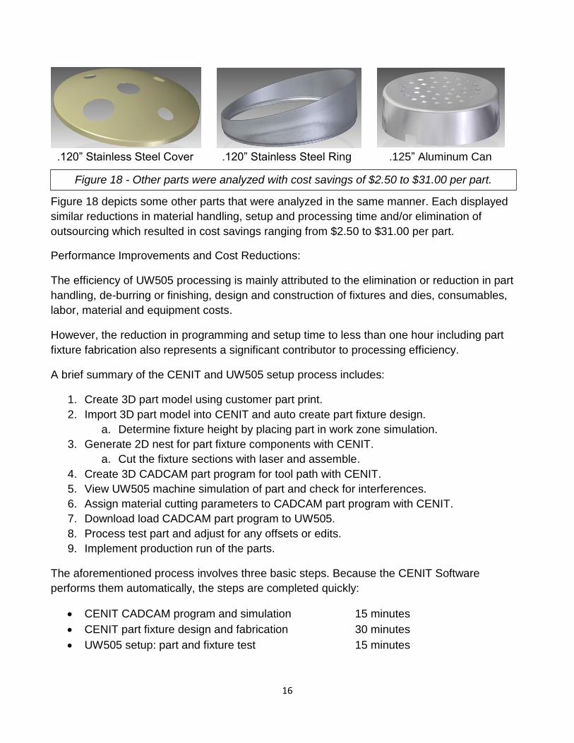
.120” Stainless Steel Cover .120” Stainless Steel Ring .125” Aluminum Can
Figure 18 depicts some other parts that were analyzed in the same manner. Each displayed
similar reductions in material handling, setup and processing time and/or elimination of
outsourcing which resulted in cost savings ranging from $2.50 to $31.00 per part.
Performance Improvements and Cost Reductions:
The efficiency of UW505 processing is mainly attributed to the elimination or reduction in part
handling, de-burring or finishing, design and construction of fixtures and dies, consumables,
labor, material and equipment costs.
However, the reduction in programming and setup time to less than one hour including part
fixture fabrication also represents a significant contributor to processing efficiency.
A brief summary of the CENIT and UW505 setup process includes:
1. Create 3D part model using customer part print.
2. Import 3D part model into CENIT and auto create part fixture design.
a. Determine fixture height by placing part in work zone simulation.
3. Generate 2D nest for part fixture components with CENIT.
a. Cut the fixture sections with laser and assemble.
4. Create 3D CADCAM part program for tool path with CENIT.
5. View UW505 machine simulation of part and check for interferences.
6. Assign material cutting parameters to CADCAM part program with CENIT.
7. Download load CADCAM part program to UW505.
8. Process test part and adjust for any offsets or edits.
9. Implement production run of the parts.
The aforementioned process involves three basic steps. Because the CENIT Software
performs them automatically, the steps are completed quickly:
CENIT CADCAM program and simulation 15 minutes
CENIT part fixture design and fabrication 30 minutes
UW505 setup: part and fixture test 15 minutes
Figure 18 - Other parts were analyzed with cost savings of $2.50 to $31.00 per part.

17
ROI AND PROJECT PAYBACK
The ROI and Project Payback are estimated to be approximately 1.5 years before tax
incentives and depreciation considerations. The calculation is based on an extrapolation of
actual per part cost savings and estimated profits from new business. The first nine months of
operation was one shift/day, and the next three months was projected to be two shifts per day.
The 2nd year assumed two shift per operation or 4,000 hours per year operation. The chart
reflects actual and estimated data:
Assumptions:
1. Average savings for current in-house jobs: $ 5.00 per part
2. Average costs for outsourcing: $10.00 per part
3. Projected new jobs: 30,000 parts/year
4. Project UW505 Job Shop Work: 800 hours of cutting/year
5. UW505 Job Shop Rate: $155/hour
Description Annual Savings and Profits
Part Production:
In-house Part Savings (46,000 parts x $5.00/part savings) $230,000
Eliminate Outsourcing (12,500 parts x $10.00/part savings) $125,000
New Job Profits (30,000 parts x $5.00/part savings) $150,000
Job Shop Work for UW505 (800 hours x $155/hour) $124,000
TOTALS: $629,000
Assumptions:
1. Operating costs for electricity, assist gas, etc: $10.00/hour
2. R&M expenses: $ 2.00/hour
3. Interest rate on capital investment: 5.5%
Description UW505 Project Costs:
Operating Expenses (average $10.00 per hour) $ 40,000
Misc. Repair and Maintenance (average $2.00 per hour) $ 8,000
Capital Costs over five years: $136,900
Shipping, Rigging, Utilities, Preparations, etc.: $ 19,000
TOTALS: $203,900

18
CONCLUSION
Secondary cutting operations of precision 3D parts can best be achieved with the use of a 5 or
6-axis fiber laser cutting machine. Considering all factors including initial cost, operating
expenses, programming, ease of setup/changeover, cutting performance, accuracy, cut quality
and reliability, a multi-axis fiber laser work station represents the most effective manufacturing
solution. After completing nine months of operation including the learning curve, Kryton
summarized the benefits of the Rofin UW505 Fiber Laser Work Station:
1. Multiple production runs of over (70) different parts have been successfully performed.
2. Machine operation has expanded from one shift per day to two shifts per day.
3. Processing flexibility has been realized.
a. Higher quotation rate
b. Faster prototyping of 3D parts.
c. Ability to efficiently process alloys: stainless, aluminum, copper, brass.
4. Multiple processing steps have been reduced to one laser cutting step.
a. Reduction in lead times and more production output.
b. Elimination of drills, blades and consumable expenditures.
c. Lower handling and labor content
5. Efficient fixture generation has reduced tooling production costs and expenses.
6. Reduction of re-work has been realized for many jobs.
a. Major reduction in de-burring and secondary finishing.
b. Elimination hand tool re-work.
7. Better part accuracy and repeatability has been achieved on all parts.
a. Hole and cutouts display tighter tolerances.
b. Position referencing of holes and cutouts demonstrate better accuracy.
8. Operator safety has been enhanced by reducing part handling and hazards.
a. No sharp edges.
b. Elimination of hazardous secondary operations.
9. Outsourcing has been dramatically reduced for challenging parts.
a. Increase in profitability.
b. Better control of production lead times.