Embed Size (px)
Citation preview

1
Case of the Mock Trial
1 Case Summary
Pony Corp. (P) filed a patent application for an invention relating to a piston
compressor. The patent based on this application was registered on 21 Nov. 2007
(JP/US/EP 35811710. Patented Invention, Patent).
Donkey Corp. (D) started to produce and sell piston compressor Y (Product Y) from 30
Mar. 2010. Upon research and development, D launched piston compressor X (Product
X) on 5 May 2015. Since then, Product X has become the main product of D.
P sent a cease and desist letter to D on 16 Sep. 2017, asserting that Products X and Y
fell within the technical scope of the Patented Invention.
However, D refuted that Product Y does not fall within the technical scope of the
Patented Invention. D also refuted that although Product X does fall within the technical
scope of the Patented Invention, Patent should be invalidated because the Patented
Invention lacks an inventive step (non-obviousness) based on the invention pertaining
to Patent Gazette 34085 (Gazette 085, Main Cited Invention) and the invention
pertaining to Patent Gazette 63165 (Gazette 165, Sub Cited Invention).
P filed the infringement lawsuit against D on 4 Jul. 2018, in which P seeks [i] an
injunction against the act of producing and assigning Product X, Y and [ii] a payment of
450M Yen (4.5M US Dollars, 4.5M Euro) for Product X, 50M Yen (0.5M US Dollars, 0.5M
Euro) for Product Y, 500M Yen (5M US Dollars, 5M Euro) in total.
2 Brief illustration on a piston compressor
(1) Piston compressor
A piston compressor can be used as a refrigerant compressor for an automobile air
conditioning system.
In a piston compressor, the swash plate(1) is supported by the rotary shaft(2) and

2
rotates with it integrally. The piston(4)
makes reciprocal motion through this
swash plate(1) in accordance with the
rotation of the rotary shaft(2). This
reciprocal motion of the piston(4) makes
refrigerant be taken into the cylinder(3),
compressed in it, then exhausted from it.
(Abr. General editor; Kenichi Fujiwara, Author and
editor; A study group for car air-con “Car air-con”
(Sankaidou, 1996) p113)
(2) Reed valve compressor / Rotary valve compressor
In a piston compressor, refrigerant shall be taken into compression chambers(3) from
suction chambers(10), and its one-way current shall be controlled by suction valves.
Piston compressor is classified into reed valve compressor and rotary valve
compressor according to the differences in suction valves structures.
Reed valve compressor uses one-way flap valves (reed valve) as such suction valves.
The Main Cited Invention corresponds to a reed valve compressor.
Rotary valve compressor is rather complex. In a rotary valve compressor, rotary
valves are integrated with a rotary shaft(2). Rotary valves have, on the outer
peripheral surfaces, the outlets of introduction passages(12). Shaft hole(5) has, on the
inner peripheral surface, the inlets of suction passages(13). The outlet of introduction
passages(12) intermittently communicate with the inlets of the suction passages(13) in
accordance with the rotation of the rotary shaft(2). This intermittent communication is
equivalent to the openings and closings of valves. The Patented Invention and the Sub
Cited Invention correspond to a rotary valve compressor.
Concerning exhaust valves(7) structure, same structures are adopted in both reed
valve compressor and rotary valve compressor.
(3) Problems in a piston compressor

3
In a piston compressor,
the compression reaction
force is generated on the
piston(4) at the time of
compressing motion. As the
piston(4) is being
synchronized with the
swash plate(1), the
compression reaction force
acts on the swash plate(1)
as the reaction force (P).
Since the reaction force (P)
acts on a position away from the
center of the rotary shafts(2), the
reaction force (P) generates
moment(M) which may cause the tilt of the
rotary shaft(2).
The tilt of the rotary shaft(2) disturbs the
smooth rotation of the rotary shaft(2).
Furthermore, in a rotary valve compressor,
due to the tilt of the rotary shaft(2), clearance
between the outer peripheral surfaces of rotary valves(6) and the inner peripheral
surface of a shaft hole(5) tends to become wide. It causes refrigerant to leak into the
clearance through the inlets of suction passages(13).
(4) Means adopted in a prior art
In a conventional piston compressor, rolling bearings(9) were used between the outer
peripheral surfaces of rotary valves(6) and the inner peripheral surface of a shaft
hole(5). Those rolling bearings(9) held the rotary shaft(2) so firmly that they could
prevent the tilt of the rotary shaft(2) and mitigate the expansion of the clearance even
when the reaction force (P) generates moment(M) which may cause the tilt of the
rotary shaft(2).
However, rolling bearings(9) were obstacles for cost reduction of compressors because
they were expensive and assembly procedures became complex by using them.
The Sub Cited Invention adopts such rolling bearings(9) in prior art in order to
mitigate the tilt of the rotary shaft(2).
Enlarged view of the clearance between the rotary shaft(2) and the shaft hole(5)

4
Components other than rolling bearings(9) are adopted in the Patented Invention
and the Main Cited Invention respectively for mitigating the tilt of the rotary shaft(2).
3 Patented Invention
(1) Claim No.1
A: A piston compressor,
B: which has rotary
valves(6), has rotary
shafts(2) that are integrated
with said rotary valves(6)
and has a shaft hole(5) that
accommodates said rotary
valves(6) in a rotatable
manner,
C: which causes
pistons(4) to make
reciprocal motions through
swash plates(1) in
accordance with the rotation Drawing of the Patented Invention
of said rotary shaft(2),
D: said shaft hole(5) has, on the inner peripheral surface, the inlets of suction
passages(13) to intake refrigerant into compression chambers(3),
E: said rotary valves(6) have, on the outer peripheral surfaces, the outlets of
introduction passages(12) that intermittently communicate with the inlets of said
suction passages(13) in accordance with the rotation of said rotary shafts(2),
F: the inner peripheral surface of said shaft hole(5) directly supports the outer
peripheral surfaces of said rotary valves(6) and the clearance between them is set as
less than 20μm.
(2) Corrected claim or dependent claim
The claim can be corrected during the litigation procedure. In the country in which
claim correction is unrealistic in this procedure, a dependent claim(Claim No.2) can be
set beforehand. While correcting the claim or setting the dependent claim, each country
is only allowed to add the following underlined elements to the abovementioned
Element E.
E’ : said rotary valves(6) have, on the outer peripheral surfaces, the outlets of

5
introduction passages(12) that intermittently communicate with the inlets of said
suction passages(13) in accordance with the rotation of said rotary shafts(2), the outer
peripheral surfaces of said rotary valves(6) are cylindrically-shaped, except for the
outlets of said introduction passages(12),
(3) Description
[0001] This invention relates to a rotary valve compressor.
[0002] Rotary valve compressor is superior to reed valve compressor in terms of
energy conversion efficiency.
[0003] In a rotary valve compressor, the compression reaction force generates
moment(M) which may cause the tilt of the rotary shaft(2). The tilt of the rotary
shaft(2) tends to make clearance between the outer peripheral surfaces of rotary
valves(6) and the inner peripheral surface of shaft hole(5) wider. It causes the problem
that refrigerant leaks into the clearance through the inlets of suction passages(13).
[0004] In the conventional rotary valve compressor, rolling bearings were used to
hold the rotary shaft(2) firmly, between the outer peripheral surfaces of rotary
valves(6) and the inner peripheral surface of shaft hole(5). However, rolling bearings
were obstacles for cost reduction of compressors because they were expensive and
assembly procedures became complex by using them.
[0005] Inventors recognized it crucial that the clearance between the inner
peripheral surface of the shaft hole(5) and the outer peripheral surfaces of the rotary
valves(6) should be adjusted precisely. Surprisingly, inventors found that the clearance
being set as less than 20μm mitigates the expansion of it drastically without using
rolling bearings.
[0030] This invention can reduce production costs because it does not have to use
rolling bearings.
(4) Drawings
Above “Drawing of the Patented Invention” is shown as description of one of the
embodiments. In all drawings to describe embodiments, the outer peripheral surfaces
of rotary valves(6) are being cylindrically-shaped except for the outlets of introduction
passages(12).
(5) Prosecution history
Initial claim did not mention “the clearance between them is set as less than 20μm”,
therefore, there was no limitation on the width of the clearance between the inner
6
peripheral surface of the shaft hole(5) and the outer peripheral surfaces of the rotary
valves(6).
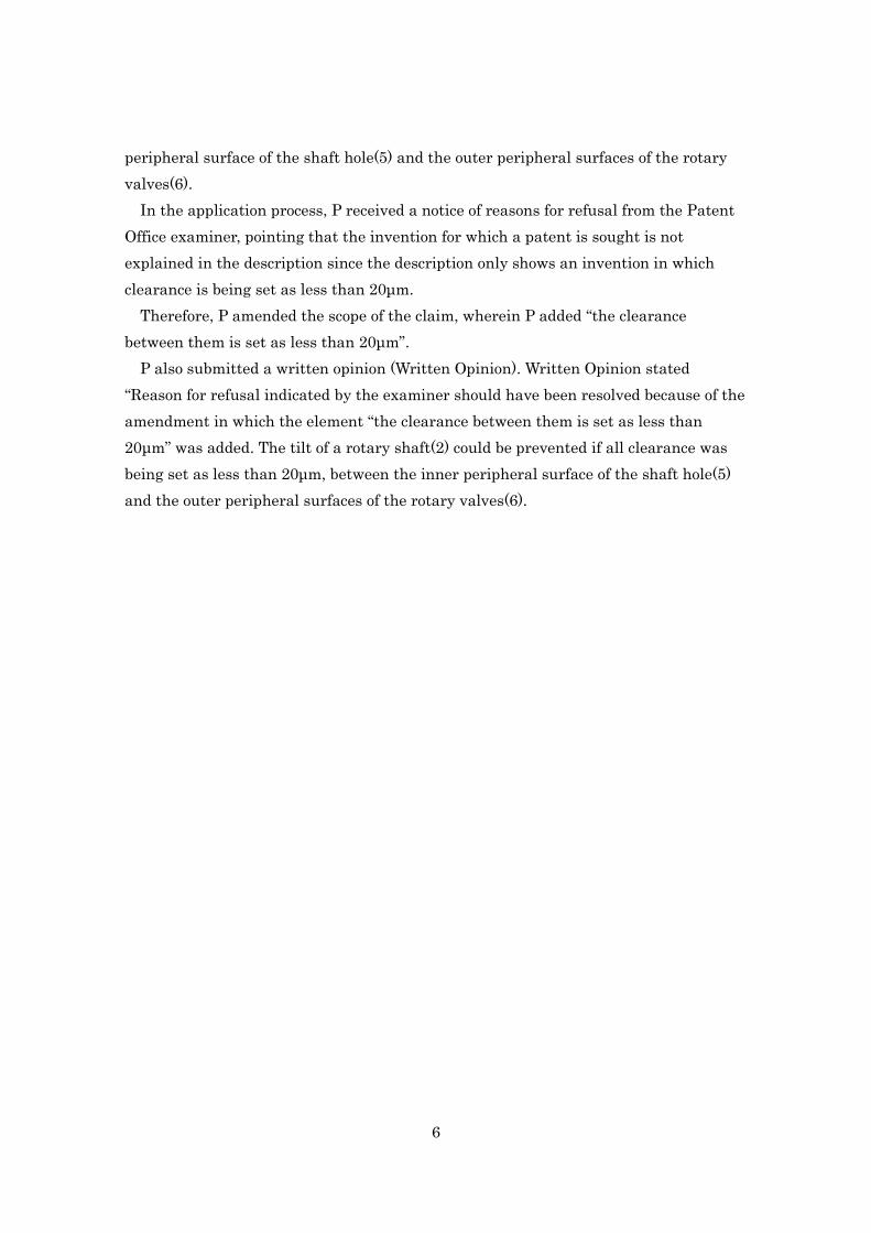
In the application process, P received a notice of reasons for refusal from the Patent
Office examiner, pointing that the invention for which a patent is sought is not
explained in the description since the description only shows an invention in which
clearance is being set as less than 20μm.
Therefore, P amended the scope of the claim, wherein P added “the clearance
between them is set as less than 20μm”.
P also submitted a written opinion (Written Opinion). Written Opinion stated
“Reason for refusal indicated by the examiner should have been resolved because of the
amendment in which the element “the clearance between them is set as less than
20μm” was added. The tilt of a rotary shaft(2) could be prevented if all clearance was
being set as less than 20μm, between the inner peripheral surface of the shaft hole(5)
and the outer peripheral surfaces of the rotary valves(6).

7
4 Products X and Y
In Product X, the outer peripheral Overall structure of D’s product
surface of the rotary valve(6) is
cylindrically-shaped. All other
components fall within the
technical scope of the Patented
Invention.
In Product Y, the outer
peripheral surface of the rotary
valve(6) has concave portions,
which high-pressure gas is
introduced into, although most
of it is cylindrically-shaped. All
other components fall within
the technical scope of the
Patented Invention.
Product X Product Y
5 Main Cited Invention
(1) Distinctive Features
Gazette 085 describes the Main Cited Invention. The Main Cited Invention
corresponds to a reed valve compressor.
One of the embodiments shows; a shaft hole(5) accommodates a rotary shaft(2) in a
rotatable manner, and pistons(4) make reciprocal motion through swash plates(1) in
accordance with the rotation of the rotary shaft(2).
8
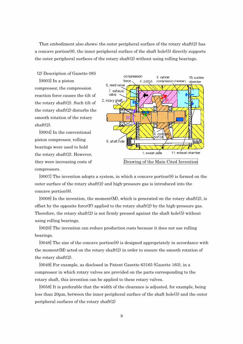
That embodiment also shows; the outer peripheral surface of the rotary shaft(2) has
a concave portion(8), the inner peripheral surface of the shaft hole(5) directly supports
the outer peripheral surfaces of the rotary shaft(2) without using rolling bearings.
(2) Description of Gazette 085
[0003] In a piston
compressor, the compression
reaction force causes the tilt of
the rotary shaft(2). Such tilt of
the rotary shaft(2) disturbs the
smooth rotation of the rotary
shaft(2).
[0004] In the conventional
piston compressor, rolling
bearings were used to hold
the rotary shaft(2). However,
they were increasing costs of Drawing of the Main Cited Invention
compressors.
[0007] The invention adopts a system, in which a concave portion(8) is formed on the
outer surface of the rotary shaft(2) and high-pressure gas is introduced into the
concave portion(8).
[0008] In the invention, the moment(M), which is generated on the rotary shaft(2), is
offset by the opposite force(F) applied to the rotary shaft(2) by the high-pressure gas.
Therefore, the rotary shaft(2) is not firmly pressed against the shaft hole(5) without
using rolling bearings.
[0020] The invention can reduce production costs because it does not use rolling
bearings.
[0048] The size of the concave portion(8) is designed appropriately in accordance with
the moment(M) acted on the rotary shaft(2) in order to ensure the smooth rotation of
the rotary shaft(2).
[0049] For example, as disclosed in Patent Gazette 63165 (Gazette 165), in a
compressor in which rotary valves are provided on the parts corresponding to the
rotary shaft, this invention can be applied to these rotary valves.
[0058] It is preferable that the width of the clearance is adjusted, for example, being
less than 20μm, between the inner peripheral surface of the shaft hole(5) and the outer
peripheral surfaces of the rotary shaft(2)

9
(3) Drawings of Gazette 085
Above “Drawing of the Main Cited Invention” is shown as description of one of the
embodiments. In all drawings to describe embodiments, suction valves(6) are one-way
flap valves (reed valve) .
6 Sub Cited Invention
(1) Distinctive Features
Gazette 165 describes the
Sub Cited Invention. The Sub
Cited Invention corresponds to
a rotary valve compressor in a
piston compressor.
One of the embodiments
shows; rotary valves(6) and a
rotary shaft(2) are integrated,
a shaft hole(5) accommodates
rotary valves(6) in a rotatable
manner, rotary valves(6) have,
on the outer peripheral
surfaces, the outlets of introduction Drawing of the Sub Cited Invention
passages(12) to introduce refrigerant
into compression chambers(3), a shaft hole(5) has, on the inner peripheral surface, the
inlets of suction passages(13) to take refrigerant into compression chambers(3), the
outlets of introduction passages(12) and the inlets of suction passages(13) are
intermittently communicated in accordance with the rotation of a rotary shaft(2),
pistons(4) make reciprocal motion through swash plates(1) in accordance with the
rotation of the rotary shaft(2). That embodiment also shows; the outer peripheral
surfaces of rotary valves(6) are cylindrically-shaped, and the inner peripheral surface
of a shaft hole(5) supports the outer peripheral surfaces of rotary shaft(2) through
rolling bearings(9).
(2) Drawing of Gazette 165
Above “Drawing of the Sub Cited Invention” is shown as description of one of the
embodiments.

Within the scope Within the scope?
Patented Invention
Corrected Invention
(or Claim No.2)
Fall within the technical scope
Patented Invention(Claim No.1) X Y
A A piston compressor, ✓ ✓
B which has rotary valves(6), has a rotary shaft(2) that is integrated with said rotary valves(6)
and has a shaft hole(5) that accommodates said rotary valves(6) in a rotatable manner, ✓ ✓
C which causes pistons(4) to make reciprocal motions through swash plates(1) in accordance
with the rotation of said rotary shaft(2), ✓ ✓
D said shaft hole(5) has, on the inner peripheral surface, the inlets of suction passages(13) to
intake refrigerant into compression chambers(3), ✓ ✓
E said rotary valves(6) have, on the outer peripheral surfaces, the outlets of introduction
passages(12) that intermittently communicate with the inlets of said suction passages(13) in
accordance with the rotation of said rotary shafts(2),
✓ ✓
F the inner peripheral surface of said shaft hole(5) directly supports the outer peripheral
surfaces of said rotary valves(6) and the clearance between them is set as less than 20μm. ✓ ?
Corrected Invention(or Claim No.2) X Y
A~D,F Same as above Same as above
E´ said rotary valves(6) have, on the outer peripheral surfaces, the outlets of introduction
passages(12) that intermittently communicate with the inlets of said suction passages(13) in
accordance with the rotation of said rotary shafts(2), the outer peripheral surfaces of said rotary
valves(6) are cylindrically-shaped, except for the outlets of said introduction passages(12),
✓ ✘
Product X Product Y
Inventive /
Obvious?
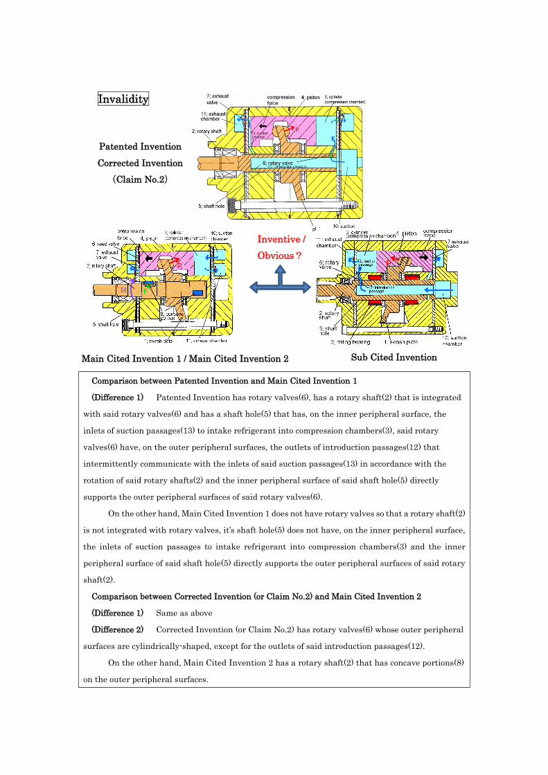
Invalidity
Comparison between Patented Invention and Main Cited Invention 1
(Difference 1) Patented Invention has rotary valves(6), has a rotary shaft(2) that is integrated
with said rotary valves(6) and has a shaft hole(5) that has, on the inner peripheral surface, the
inlets of suction passages(13) to intake refrigerant into compression chambers(3), said rotary
valves(6) have, on the outer peripheral surfaces, the outlets of introduction passages(12) that
intermittently communicate with the inlets of said suction passages(13) in accordance with the
rotation of said rotary shafts(2) and the inner peripheral surface of said shaft hole(5) directly
supports the outer peripheral surfaces of said rotary valves(6).
On the other hand, Main Cited Invention 1 does not have rotary valves so that a rotary shaft(2)
is not integrated with rotary valves, it’s shaft hole(5) does not have, on the inner peripheral surface,
the inlets of suction passages to intake refrigerant into compression chambers(3) and the inner
peripheral surface of said shaft hole(5) directly supports the outer peripheral surfaces of said rotary
shaft(2).
Comparison between Corrected Invention (or Claim No.2) and Main Cited Invention 2
(Difference 1) Same as above
(Difference 2) Corrected Invention (or Claim No.2) has rotary valves(6) whose outer peripheral
surfaces are cylindrically-shaped, except for the outlets of said introduction passages(12).
On the other hand, Main Cited Invention 2 has a rotary shaft(2) that has concave portions(8)
on the outer peripheral surfaces.
Main Cited Invention 1 / Main Cited Invention 2
Patented Invention
Corrected Invention
(Claim No.2)
Sub Cited Invention