Embed Size (px)
Citation preview

US Army Corps of Engineers Waterways Experiment Station
Technical Report ITL-95-10 September 1995
CASE Environments: A Survey of Methodologies, Capabilities, and Trends
by Rhonda J. Vickery, William A. Ward, Jr., University of South Alabama
Approved For Public Release; Distribution Is Unlimited
1995111? 063 ^WAIXKWSFECmSD 8
Prepared for U.S. Army Environmental Center

The contents of this report are not to be used for advertising, publication, or promotional purposes. Citation of trade names does not constitute an official endorsement or approval of the use of such commercial products.
O PRINTED ON RECYCLED PAPER

Technical Report ITL-95-10 September 1995
CASE Environments: A Survey of Methodologies, Capabilities, and Trends by Rhonda A. Vickery, William A. Ward, Jr.
Faculty Court West 20 School of Computer and Information Sciences University of South Alabama Mobile, AL 36688
Final report Approved for public release; distribution is unlimited
Prepared for U.S. Army Environmental Center Building E4435, Edgewood Area Aberdeen Proving Ground, MS 21010
Under Contract No. DACA39-93-K-0016
Monitored by U.S. Army Engineer Waterways Experiment Station 3909 Halls Ferry Road, Vicksburg, MS 39180-6199

ik'Jii
US Army Corps of Engineers Waterways Experiment Station
HEADQUARTERS BUILDING
FOR «FORMATION CONTACT :
PUBUC AFFAIRS OFFICE
U. S. ARMY ENGINEER
WATERWAYS EXPERIMENT STATION
3909 HALLS FERRY ROAD
VICKSBURG, MISSISSIPPI 39180-6199
PHONE: (601)634-2502
AREA OF RESERVATION. £7 »q km
Waterways Experiment Station Cataloging-in-Publication Data
Vickery, Rhonda A. CASE environments : a survey of methodologies, capabilities, and trends / by Rhonda A.
Vickery, William A. Ward, Jr.; prepared for U.S. Army Environmental Center; monitored by U.S. Army Engineer Waterways Experiment Station.
97 p. : ill.; 28 cm. - (Technical report ; ITL-95-10) Includes bibliographic references. 1. Computer-aided software engineering. 2. Computer software - Development. I. Ward,
William A. II. United States. Army. Corps of Engineers. HI. U.S. Army Engineer Waterways Experiment Station. IV. Information Technology Laboratory (U.S. Army Engineer Waterways Experiment Station) V. U.S. Army Environmental Center. VI. Title. VH. Title: A Survey of methodologies, capabilities and trends. VUI. Series: Technical report (U.S. Army Engineer Waterways Experiment Station) ; ITL-95-10. TA7W34no.ITL-95-10

Contents
iooessloQ For ;<^?^l
MIS ORAfcl 1* DTIC TAB a Unannounced a Justification
Bv Distribution/
Availability Co ÖSS
Avail and/or list $p&® i&i
A
Preface vi
1—Introduction 1
2—History of Software Development Tools 3
3—Life Cycle Models '. 7
Waterfall Model 7 Evolutionary Prototyping Model H Transformation Model 12 Spiral Model 13 Cleanroom Model 17
4—Software Specification and Design Methodologies 18
Requirements Specification 18 Design 18 Common Methodologies 19 Software Domain Methodology Considerations 26
5—CASE Tool Considerations 28
Integrated CASE, Repositories, and MetaCASE 28 Configuration Management 33 Reengineering 33 Artificial Intelligence and Reusability 36
Hypertext 37 Client-Server CASE 38 Other Considerations 38
6—CASE Tool Selection Criteria 40
Methodology 41 Utility 41
Organizational Acceptance 42 Implementation Cost 43 CASE Tool Vendor Overview 44
in

7—Conclusions 45
References 46
Appendix A: Common Methodology Tool Descriptions Al
Appendix B: CASE Vendor Descriptions Bl
Teamwork by CADRE B1 Industrial-Strength CASE Solutions by CGI B3 COHESION by Digital Equipment Corp B3 Ada Software Engineering Products by EVB B4 OMTool by General Electric B4 001 by Hamilton Technologies B5 SoftBench by Hewlett-Packard B5 PowerTools by Iconix B6 Software through Pictures by IDE B6 STATEMATE by I-Logix B7 CASE Products by KnowledgeWare, Inc B7 ERwin/ERX and BPwin by Logic Works B8 ObjectMaker by Mark V Systems B9 PRIDE Information Factory by M. Bryce & Associates B9 ObjectCraft by Object Oriented Technologies BIO Database Management Tools by ONTOS BIO System Architect by Popkin Software & Systems, Inc B11 Paradigm Plus by Protosoft B11 CASE Products by Rational B12 Reengineering Products by Scandura B13 Exchange by Software One B14 Software Development Products by Software Systems Design B14 G++ by SYCO B14 Information Engineering Facility by Texas Instruments B15 CASE Products by Verflog B15 Virtual Software Factory by VSF Ltd B16 Visible Analyst Workbench by Visible Systems Corp B17 ICASE Tools by Westmount B17 CASE Products by York Software Engineering B18 DesignAid II by Yourdon B18
Appendix C: Software Technology Support Center Reports Cl
Appendix D: List of Acronyms Dl
Report Documentation Page End
IV
List of Figures
Figure 1. CASE historical development 4
Figure 2. The waterfall model 9
Figure 3. The waterfall model with feedback 10
Figure 4. The transformational model 13
Figure 5. The spiral model 15
Figure 6. Common analysis methodologies 20
Figure 7. Common design methodologies 22
Figure 8. The NIST/ECMA tool integration framework 30
Figure 9. The NIST organizational framework 34
Figure 10. Steps in the reverse engineering process 34
Figure 11. The learning curve 43

Preface
This report is published in the interest of scientific and technical information exchange; the ideas and findings contained herein should not be construed as an official position of the U.S. Army Corps of Engineers. Use of any trademarks in this report is not intended in any way to infringe on the rights of the trademark holder.
The authors thank Dr. Windell F. Ingram and Mr. Scott Smith for reviewing this report. The production of this report was sponsored by the U.S. Army Environmental Center (AEC) and funded through the U.S. Army Engineer Waterways Experiment Station (WES) Information Technology Laboratory (ITL) under Contract No. DACW39-93-K-0016 from March 3,1993 to December 31, 1993.
Mr. Mark N. Bovelsky was Chief of the Information Management Branch, AEC, during the preparation of this report. The contract was monitored by Dr. Windell F. Ingram, Chief, Computer Sciences Division, ITL. Dr. N. Radhakrish- nan was Director, ITL, Dr. Robert W. Whalin was Director of WES, and COL Bruce K. Howard, EN, was Commander.
VI

1 Introduction
Computer programming has evolved from a single person activity of develop- ing smaller straightforward applications to an organized discipline involving a team of programmers developing large complex software systems. With the realization in the late 1960s that programming well was simply not enough to build better software, researchers began to formalize the activity of software development by applying principles of good engineering practice (Ghezzi, Jazayeri, and Mandrioli 1991). Since then, the software engineering discipline has continued to mature, similar to the historical trends in other engineering dis- ciplines. The development of large complex systems is significantly different from the development of smaller systems, and requires a change in the funda- mental approach. This new engineering approach includes better management, organization, tools, theories, methodologies, and techniques (Ghezzi, Jazayeri, and Mandrioli 1991).
A large part of coping with the development of large software projects is being able to provide a quality product that can be maintained. In order to better accomplish this, automation of as much of the process as possible is desired to alleviate human errors. Initially this was accomplished with programming tools such as compilers and debuggers. Then computer aided software engineering (CASE) tools were developed to aid the specification and design stages of development, which came to be known as upper CASE tools. Likewise the pro- gramming development tools are known as lower CASE tools. Now the trend is towards CASE tools that encompass the entire development cycle and work together to give the software engineer a common interface with shared data exchanged between tools. In other words, to achieve the desired levels of quality while properly managing the development effort, these integrated CASE tools must automate the entire process.
The future success of software engineering is inextricably woven with the success of CASE tools. The complexity of the systems is such that the first can no longer exist without the second. Two important trends have made this more important than ever (Ghezzi, Jazayeri, and Mandrioli 1991). The first is the increase in cost for developing software. Years ago, software costs were insignificant compared to the hardware costs for a system. Today, the roles are reversed, and the rising costs of software development make it more economical
Chapter 1 Introduction

to invest in and use CASE tools for development. A second contributing trend is that software development is no longer just a matter of coding; it is an integrated and complex task involving an entire life cycle. The main goals for software using CASE are the same as those for software engineering:
• Automation of software development tasks
• Quality
• Maintainability
• Correctness and Reliability
• Reusability
• Performance
Other important considerations include: user friendliness, portability, understan- dability, verifiability, interoperability, timeliness, and visibility.
The goals of this paper are to provide some background on the development of CASE tools and how they enhance the software development process. A presentation of the major considerations behind the use of different CASE tools is made, along with a cross-section of the CASE products currently available on the market.
Chapter 1 Introduction
2 History of Software Development Tools
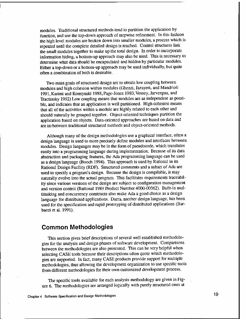
The evolution of software development tools depended heavily on the types of applications being developed, which in turn determined which methods were used (Norman and Chen 1992). These complex methods required more sophisti- cated tools to assist in the development process. The timeline illustrating the relationships between applications, methods, and tool development is shown in Figure 1.
In the early 1970s applications were written with third generation languages for batch-oriented processing systems (Norman and Chen 1992). By the late 1970s online interactive processing with rapidly maturing database management systems and decision support systems became common. High-level language compilers supported the early structured programming methods, and code gen- erators were introduced by the end of the decade to accelerate the implementa- tion process in areas where performance was not an issue. Interactive program- ming environments and text-based upper CASE tools enhanced the latest metho- dologies of information systems planning, structured analysis, and structured design. Since distributed systems were not yet available, these first generation CASE tools were also mainframe based.
The set of UNIX1 utilities known as the Programmer's Workbench is one of the most apparent examples of first generation software development tools (Dolotta and Mashey 1976,Dolotta, Haight, and Mashey 1978). These utilities include the Source Code Control System (SCCS), the Modification Request Con- trol System (MRCS), and make. SCCS is used to manage version control of modules. Source code, data, and any other type of textual information can be stored as modules and managed by the SCCS such that all changes are recorded. A module can then be recreated as it existed at any point during its development. A Modification Request Control System (MRCS) utility is available to track change requests, error reports, and modifications to the application being developed.
1 UNIX is a trademark of X/Open.
Chapter 2 History of Software Development Tools

1970-
1975-
1980-
• High Level Language Compilers
• Interactive Programming Environments
• Structured Text Based Upper CASE
Code Generators
• 4th Generation Languages
• Structured Method & Graphics Based CASE
Structured Programming
1990-
1985- , . „ . • Integrated Project
Support Environments
• Information Engineering Based CASE
• Reverse Engineering CASE
• CASE Shells
• Repository Based CASE
• Intelligent CASE
• Collaborative CASE
1995H . Integrated CASE Environments
Structured Design
Structured Analysis
Information Systems Planning
Software Metrics
Prototyping
Information Engineering
Participatory Design
Formal Methods
Object-oriented Methods
Software Process Management
Integrated Methods
Batch Transaction Processing Methods
On-line Transaction Processing Systems
Decision Support Systems
• Real-time Systems
• Expert Systems
• Strategic Information Systems
• Executive Information Systems
Multimedia Systems
Integrated Systems
Figure 1. CASE historical development (adapted from (Norman and Chen 1992, p. 14); © 1992 IEEE, reprinted by permission)
Chapter 2 History of Software Development Tools

Perhaps the most widely used component of the workbench is make. It is used to automate the updating of object files, libraries, and executable programs in projects of all sizes. Those files which are older than the files from which they are constructed, may be automatically rebuilt using make. The former files are referred to as targets while the latter are termed prerequisites or dependents. For instance, if an object module in a library is older than its corresponding source module, make may be used to automate the recompilation of the source module and update the object module. Unfortunately, use of make requires the construc- tion of often complicated and arcane makefiles which specify the targets, prere- quisites, and update activities. Furthermore, make determines whether or not a target is out of date merely by checking the time stamp on the target file, and not by examining the file's contents. Various attempts have been made to improve make; see (Oram and Talbot 1991).
The Programmer's Workbench also provides extensive documentation facili- ties to assist the developers in their activities. Information is passed between the tools using textual byte streams called pipes, thus providing a simple means of integration. Many vendors have modernized the workbench by providing X interfaces to the various tools. These utilities help automate the code generation process and still play a valuable part in many UNIX software development environments.
Rising maintenance costs for real-time software systems written for the Department of Defense (DoD) motivated the introduction of Ada as a program- ming language in the early 1980s. Because of the complexity of these systems, more fully integrated project support tool sets such as the Rational environment were introduced (Long 1992). Second generation CASE tools were primarily designed to support the structured design methods developed in the 1980s, and differed from first generation tools because they were graphics based. Dataflow diagrams and structure charts were two methodologies commonly included. Expert systems, higher level business applications, and multimedia applications were also in demand. A proliferation of software development tools such as 4th generation languages, graphics based CASE, information engineering based CASE, and reverse engineering CASE emerged. The development of these tools was impacted by several new methodologies including: prototyping, information engineering, and participatory design. Software performance issues were addressed by the introduction of software metrics. By 1990, object-oriented (00) methodologies had been developed to amend shortcomings found in struc- tured analysis and design techniques. Integrated tools developed in this decade tended to use proprietary interfaces and data dictionary storage. Rarely could tools offered by other vendors be integrated. A case study of one company's experience during this period regarding the implementation of a software development environment is given by (Penedo and Stuckle 1990); a broad histor- ical perspective of CASE enviroments up to 1992 is given by (Brown, Earl, and McDermid 1992).
The 1990s should be the decade of integration in that an organization will find CASE tools to implement every aspect of the software development environment, from high level project management tasks to low level code
Chapter 2 History of Software Development Tools

generation. The concept of shared data resources means that information will only have to be entered once (theoretically) and can then be manipulated and used at all levels of the organization. CASE tools will be collaborative, reposi- tory based, and incorporate artificial intelligence. Hypertext and databases will also be extensively used. Vendors will design their tools based on open system standards so that they will work with products supplied from other vendors. Although many companies will provide a comprehensive CASE solution as one tool, buyers will not be limited to one vendor, but will be able to construct their own customized multivendor integrated environment. As software project management features are incorporated, people from all levels of the organization will be able to access project data and participate in the application being developed. These CASE tools will include the best of the analysis and design methods, providing an integrated methodology tailored to the specific organiza- tion. As more applications are developed for the increasing number of distri- buted systems, the applications themselves will become more integrated. All of these trends will be discussed in greater detail in subsequent chapters. Further information on the current state of the practice with respect to CASE may be found in a variety of sources; see, for instance (Spun and Layzell 1992),
In essence, the third generation of CASE tools must meet the new challenges facing information systems organizations to automate the production of software for ever more complex systems. CASE must be not only cost-effective and flexi- ble for current methods, but adaptable to future methods. The ability to integrate with other software development tools will be the main characteristic of this gen- eration of CASE tools.
Chapter 2 History of Software Development Tools

When software development required only a single person, typically they were the users of their own products. That person designed the application in their own style, coded it in some language, and tested it. Bugs and enhance- ments were easily managed without a formal process. This code-and-fix model was adequate when the software could be well understood by one person and was straightforward to implement (Ghezzi, Jazayeri, and Mandrioli 1991). The recognition that this model could not be used for the production process of com- plex applications led to the concept of a software development life cycle.
Several structured models have been created to precisely describe this life cycle in order to better control and predict the process. They all represent a series of stages with some criteria to determine when to progress to another stage. The most common models are presented in this paper with implications for CASE tools:
• Waterfall Model
Waterfall Model with Feedback
Evolutionary Prototyping Model
• Transformation Model
Spiral Model
• Cleanroom Model
Waterfall Model
The waterfall software life cycle model naturally supports the structured analysis and design techniques which originated in the 1970s. These techniques were implemented without the aid of modern CASE tools. The manual process tended to progress through distinct phases, with specific documentation require- ments for the completion of each phase. The customer may also require periodic
Chapter 3 Life Cycle Models
•
•
•

generation. The concept of shared data resources means that information will only have to be entered once (theoretically) and can then be manipulated and used at all levels of the organization. CASE tools will be collaborative, reposi- tory based, and incorporate artificial intelligence. Hypertext and databases will also be extensively used. Vendors will design their tools based on open system standards so that they will work with products supplied from other vendors. Although many companies will provide a comprehensive CASE solution as one tool, buyers will not be limited to one vendor, but will be able to construct their own customized multivendor integrated environment. As software project management features are incorporated, people from all levels of the organization will be able to access project data and participate in the application being developed. These CASE tools will include the best of the analysis and design methods, providing an integrated methodology tailored to the specific organiza- tion. As more applications are developed for the increasing number of distri- buted systems, the applications themselves will become more integrated. All of these trends will be discussed in greater detail in subsequent chapters. Further information on the current state of the practice with respect to CASE may be found in a variety of sources; see, for instance (Spurr and Layzell 1992),
In essence, the third generation of CASE tools must meet the new challenges facing information systems organizations to automate the production of software for ever more complex systems. CASE must be not only cost-effective and flexi- ble for current methods, but adaptable to future methods. The ability to integrate with other software development tools will be the main characteristic of this gen- eration of CASE tools.
Chapter 2 History of Software Development Tools

3 Life Cycle Models
When software development required only a single person, typically they were the users of their own products. That person designed the application in their own style, coded it in some language, and tested it. Bugs and enhance- ments were easily managed without a formal process. This code-and-fix model was adequate when the software could be well understood by one person and was straightforward to implement (Ghezzi, Jazayeri, and Mandrioli 1991). The recognition that this model could not be used for the production process of com- plex applications led to the concept of a software development life cycle.
Several structured models have been created to precisely describe this life cycle in order to better control and predict the process. They all represent a series of stages with some criteria to determine when to progress to another stage. The most common models are presented in this paper with implications for CASE tools:
• Waterfall Model
• Waterfall Model with Feedback
• Evolutionary Prototyping Model
• Transformation Model
• Spiral Model
• Cleanroom Model
Waterfall Model
The waterfall software life cycle model naturally supports the structured analysis and design techniques which originated in the 1970s. These techniques were implemented without the aid of modern CASE tools. The manual process tended to progress through distinct phases, with specific documentation require- ments for the completion of each phase. The customer may also require periodic
Chapter 3 Life Cycle Models

reviews at critical points in the process. Although the exact definition of the specific phases can vary, the basic flow of the model is shown in Figure 2. The cascade of phases represents a disciplined software methodology followed throughout application development. Each phase naturally flows into the next, with specific documents required for each (Ghezzi, Jazayeri, and Mandrioli 1991):
• Feasibility Study - The problem is defined, alternate solutions considered, and resources, costs, and dates determined. A feasibility study document is pro- duced.
Requirements Analysis and Specification - The requirements for the applica- tion, as well as for the development and maintenance process are determined. These may include quality control and system test procedures. A require- ments specification document is produced; optionally a user manual and sys- tem test plan are also produced.
Design and Specification - The software architecture, including a high level description of how the application will implement the system requirements, is specified. The software is separated into modules and intermodule relation- ships are described. This phase may be further broken down into high-level and detailed design, but the functions performed at each level varies consid- erably. One or more design specification documents are produced.
Coding and Module Testing - The application is written in a programming language and testing of individual modules is done. Coding inspections are conducted to check for quality control criteria such as structured program- ming practices and performance issues. Actual code and possibly module testing results are produced.
Integration and System Testing - Application modules are incrementally added and tested with the larger components as part of integration testing. System level testing of application requirements is then performed. Test result documentation is produced.
Delivery - The application is officially released to customers. Selected custo- mers may have performed beta testing on the product before its official release to determine product readiness. If the application is developed for one particular customer, a sign-off document may be required for its official release.
• Maintenance - Changes are made to the released application to correct any remaining errors (corrective maintenance), adapt it to changes in the environ- ment (adaptive maintenance), and add enhancements (perfective mainte- nance). Depending on the impact of a change, several of the previous phases may be revisited.
The waterfall life cycle model has been implemented by the DoD in the development of real-time software (Ghezzi, Jazayeri, and Mandrioli 1991). The
•
Chapter 3 Life Cycle Models

Feasibility Study
V Requirements Analysis and Specification V
Design and Specification
V
Coding and Module Testing V
Integration and System
Testing v
Delivery
V
Maintenance
J
Figure 2. The waterfall model (adapted from (Ghezzi, Jazayeri, and Mandrioli 1991, p. 361); © 1991, reproduced by permission of Prentice-Hall, Inc., Englewood Cliffs, NJ)
military standard MIL-STD-2167A has been used to specify the process stages and the documentation standards for each phase. The actual stages are easily mapped to the ones described above.
A major problem with this type of development process is that many errors are not discovered until the later stages, making it more costly to correct, espe- cially if they result from problems in the high level requirements specification. What is not apparent from this model is how changes are implemented in the process (i.e. at what stage), or even whether high level documentation is ade- quately updated for changes. The description of the waterfall model depicts the development process as being linear, always progressing forward into the next phase, after the current phase is complete. In actuality, each later stage of imple- mentation must provide feedback to the previous phases as errors are found and the design is revised. A more realistic version of this model is illustrated in Fig- ure 3, which shows the waterfall model with feedback to previous stages of development.
Although maintenance is shown as only one of seven phases, at least 60% of the total development cost is attributed to this phase (Ghezzi, Jazayeri, and Man- drioli 1991). About 40% of this maintenance cost is divided equally between
Chapter 3 Life Cycle Models

Feasibility Study
V Requirements
- Analysis and Specification
1 i
V
Design and Specification
1 ,.
V Coding and
Module Testing
i\
V Integration
- and System Testing
A
V
Delivery h
V
A
Figure 3. The waterfall model with feedback (adapted from (Ghezzi, Jazayeri, and Man- drioli 1991, p. 372); © 1991, reproduced by permission of Prentice-Hall, Inc., Englewood Cliffs, NJ)
corrective and adaptive maintenance, while perfective maintenance is responsi- ble for over 50%. In fact maintenance has taken on such importance that Acly (Acly 1988) revises the traditional CASE definition to be CADME, computer- aided development and maintenance environments. The waterfall model does not accurately represent the maintenance phase, since it is oriented towards one delivery date. The model must be revised to allow for multiple separate water- falls representing incremental versions. This is described more fully under the evolutionary prototyping model.
Since most of the CASE tools are not limited to any particular life cycle model, they can be used with the waterfall model despite its shortcomings. However, because the latest CASE environments offer extensive process support features, many companies have chosen other life cycle models to more accu- rately represent their actual development process.
10 Chapter 3 Life Cycle Models

Evolutionary Prototyping Model
The evolutionary life cycle model addresses some of the shortcomings of the waterfall model by formally introducing the concept of prototyping (Connell and Shafer 1989,Ghezzi, Jazayeri, and Mandrioli 1991, Luqi and Ketabchi 1988). The rationale for this approach is that often the actual requirements for operation of the application are only determined after the product is developed. In other words, the customer may not really know what they want until after a working application is presented to them. At that time, the customer may realize that what was developed is not what they really wanted, and major redesign is required.
One simplistic version of the evolutionary model involves the quick-and-dirty creation of a throwaway prototype to determine what the actual application requirements should be. Once enough customer feedback is gathered, the real application is developed from scratch using the waterfall model. However, this approach still does not allow for feedback during the development process, nor does it eliminate the long time lag between the specification of the requirements at an early stage, and the actual application delivery date.
A better approach would be to use an incremental implementation model (Ghezzi, Jazayeri, and Mandrioli 1991). The waterfall model is followed through the analysis and design phase, to identify useful subsets and necessary interfaces of the application. Then various software components can be imple- mented, tested, and delivered to the customer incrementally, based on priorities. This process may be further extended to each individual phase in the life cycle by defining each increment as part of the system objectives and architecture. For each increment, a distinct waterfall process is followed through all design phases, resulting in a multiple waterfall model. As each is developed, feedback is provided back to earlier stages, to be incorporated into successive versions. In essence, the maintenance phase disappears, since all changes are implemented into a specific version with its own waterfall process. The concept of an evolu- tionary prototype describes the progressive transformation of the initial proto- type into the final desired application. This approach alleviates the time lag between requirements specification and product delivery, and allows errors discovered in later phases to be incorporated into the next scheduled version.
Although the evolutionary life cycle model provides several distinct advan- tages over the waterfall model, it also has some disadvantages. If discipline is not consistently enforced, it may be difficult to distinguish it from the code-and- fix model, which is often associated with poor planning and spaghetti code (Boehm 1988). The evolutionary approach is also based on the assumption that the target operating environment can accommodate application development in an incremental and predictable fashion. A good example of this is a situation in which new software is to replace a large existing system one section at a time (Boehm 1988). Temporary "bridges" between the new incrementally evolving application and the old application may be difficult to implement if the old software is poorly modularized. Much effort may be wasted on hard-to-change code, when a long range architectural and usage approach may be better.
Chapter 3 Life Cycle Models 11

The most important feature of the evolutionary approach that CASE tools must support is version control. In order for the process to be successfully automated, separate versions of the documentation, code, and any other miscel- laneous files must be kept. In more general terms this is known as configuration management. Not only is it desirable to keep older versions of the application, but doing so may be a contractual requirement. This allows regression back to an earlier version if the latest one is tested and found to be defective. Configuration management also supports the concept of software families. For example, different versions may be required for different hardware platforms. Several vendors support configuration management as an integral part of their CASE toolset, while others provide a separate tool which may be integrated with other vendor's products. See Appendix B for a complete description of CASE tool capabilities by vendor.
Transformation Model
The transformation life cycle model is based on the formalization of specification requirements (Ghezzi, Jazayeri, and Mandrioli 1991). The initial requirements are specified using an abstract formal representation, and are then successively transformed into less abstract representations, until an executable application is derived. If the first abstract formal representation can be executed or "animated" to show how the application will operate, then it can be viewed as a prototype. The final application is the optimized version, derived from the pro- totype, that is actually be delivered to the customer. Figure 4 illustrates the steps involved in the transformation process (Ghezzi, Jazayeri, and Mandrioli 1991).
The abstract formal specification of the requirements may be expressed in any high level language. However, a language such as Prolog which is a natural expression of predicate calculus may be the most appropriate (Ghezzi, Jazayeri, and Mandrioli 1991,Symonds 1988). High level rules may be used to help describe the behavior of the system, making the automation of the process con- ducive to the use of artificial intelligence. Although many CASE tools have been developed around some sort of automated assistant or knowledge base (Karimi and Konsynski 1988, Luqi and Ketabchi 1988,Puncello et al. 1988,Symonds 1988) they tend to be based more on the evolutionary rather than the transformation approach. Some researchers believe that all successful CASE tools will eventually incorporate artificial intelligence to help manage the enor- mous amount of information and provide the type of assistance that a software engineer requires to build an application (Baiser 1983, Forte and Norman 1992, Norman and Chen 1992).
Since the transformation model is mathematically based, it has been used for small applications as an alternate method for proving program correctness (Ghezzi, Jazayeri, and Mandrioli 1991). This approach is a constructive means of proving a program is correct by starting with formal specifications and succes- sively transforming them into an executable program. This method is fundamen- tally different from the use of program correctness proofs, which is an analytic approach done after the program is completed.
•j p Chapter 3 Life Cycle Models

Requirements Requirements
Analysis and Specification
Formal
Specifications
Reusable Components
Optimization
Verification
Recording of
Developmental History
Lower Level Specifications
Tuning
Figure 4. The transformational model (adapted from (Ghezzi, Jazayeri, and Mandrioli 1991, p. 378); © 1991, reproduced by permission of Prentice-Hall, Inc., Engle- wood Cliffs, NJ)
The transformation model addresses some of the deficiencies of the waterfall and evolutionary models, but still has some disadvantages. The main advantage is that, since the specifications are transformed into code, modifications are made directly to the requirements, and the code is regenerated. This avoids the prob- lem of maintaining code that has become poorly structured through repeated changes, and documentation is insured at the early requirements phase of development. A disadvantage of the transformation model is that, like the evolu- tionary model, it may not be appropriate for environments where an old system must be replaced in stages. Also, designs based on this approach have not been successfully scaled up to larger projects (Boehm 1988). Although there have been CASE tools developed based on the transformation model (Symonds 1988), they are primarily used in research environments to design small systems.
Spiral Model
The spiral life cycle model is viewed as a metamodel because it can accom- modate any other type of life cycle or process model (Boehm 1988, Ghezzi, Jazayeri, and Mandrioli 1991). This model provides a development framework based on the risk levels for a project. In Figure 5, the spiral model illustrates
Chapter 3 Life Cycle Models 13

how the principles of risk management guide the development process of an application (Boehm 1988). Each of the four quadrants represents a stage of the risk analysis process:
•
•
Stage 1: Determine objectives, alternatives, and constraints of the product under development (upper left quadrant of figure).
Stage 2: Evaluate the alternatives, identify and resolve risks (upper right qua- drant).
• Stage 3: Develop and verify next-level product (lower right quadrant).
• Stage 4: Plan subsequent phases (lower left quadrant).
The radius of the spiral depicts the accumulated cost. The angular dimension represents the progress through each quadrant of the model. The spiral model is a higher-level project management representation that can easily accommodate any combination of the previously discussed life cycle models. In this case the figure shows a project which uses prototyping in combination with the waterfall life cycle model. Each turn of the spiral represents the completion of a phase where evaluation of progress to date must be performed (lower right quadrant) before planning can begin for the next phase (lower left). The determination of objectives, alternatives, and constraints (upper left) must be addressed as well as the evaluation of alternatives, and identification and resolution of risks (upper right).
The spiral for an application under development would start in the upper left quadrant of Figure 5 which determines the objectives, alternatives, and con- straints for the initial phase of development. The innermost spiral considers requirements and application problems which may not yet be clearly defined. Alternatives identified in the first phase are evaluated as part of the risk analysis in the next phase of the spiral (represented by the upper right quadrant of Figure 5). Major areas of uncertainty are identified, and strategies for resolving the areas of project risk are formulated. Prototyping is one method of investigating uncertainties during this phase. Other methods include: analytic modeling, simulation, and benchmarking. The initial prototype is the basis for future evolu- tions of the product, and verification of its operation is performed in the phase represented by the lower right quadrant of Figure 5. Planning for the next itera- tion of the project development is done in the phase shown by the lower left qua- drant of Figure 5.
In succeeding turns of the spiral the risks and their associated resolution stra- tegies become more clearly defined during the risk analysis and prototyping stages. As the product becomes more mature, the conventional phases of the waterfall model are also performed (shown in the lower right quadrant). The combined model results in a more complete project plan.
Regardless of the underlying models involved, the main objective of the spiral model is to minimize and manage the overall risk during application
■| 4 Chapter 3 Life Cycle Models

Determine Objectives, Alternatives, and Constraints
Evaluate Alternatives; Identify, Resolve
Risks
Plan Next Phases
Develop and Verify
Next-Level Product
Figure 5. The spiral model (adapted from (Boehm 1988, p. 64); © 1988 IEEE, reprinted by permission)
Chapter 3 Ufe Cycle Models 15

development. Thus, while the spiral model incorporates the good features of other software process models, this risk driven approach avoids many of their problems. Examples of applications developed using the spiral model are given in (Boehm 1988, Jarke 1992)
Although using the spiral model has many advantages, there are several prob- lem areas which must be resolved before it can be successfully implemented. The spiral model has been applied to internal software developments that tend to be flexible in their commitment to specific objectives during each turn of the spiral (Boehm 1988). Contract software may not have this flexibility, and requirements may dictate what software products are delivered at specific stages during development. Therefore, risk management may be more constrained for contract software development. Other problems may arise from the lack of experience of developers who must assess and manage the areas of risk on a pro- ject. If a poorly understood area of risk is not properly managed, a project thought to be under control may actually be headed for disaster. Finally, the intermediate detail during each turn of the spiral must be supplied by the under- lying process model to insure that adequate elaboration of steps is applied at each stage and project milestones are met.
The Software Engineering Institute (SEI) has introduced a variation of the spiral model which provides a detailed description of the Taxonomy-Based Risk Identification Paradigm (Carr et al. 1993, Van Scoy 1992). This model uses an extensive questionnaire to help assess the elements of project risk. The SEI risk management model consists of five different activities:
• Risk Identification
• Analysis for the conversion of the risk identification information into decision making information.
• Planning the implementation of the decisions and actions required from the analysis stage.
• Tracking the status of risks and the actions taken to alleviate those risks.
• Controlling the risks according to plan and not allowing deviations.
• Communicating throughout the entire process.
A thorough and disciplined approach to identification and management of risks is outlined which covers the full breadth of the software development pro- cess. The SEI model extends the spiral model by providing a detailed, sys- tematic method of project risk management that can be generally applied.
1 ß Chapter 3 Life Cycle Models

Cleanroom Model
One of the major problems with conventional software process models is that many errors are not detected until the implementation and maintenance phases of development. The cleanroom model addresses this problem by emphasizing defect prevention instead of defect removal (although any defects found are removed) (Hevner 1992, Mills 1987). Instead of using standard debugging tech- niques to discover errors during the implementation stage, a human mathemati- cal verification methodology is applied. Formal analysis specification and design processes establish a rigorous mathematical foundation for verification. Testing at the system level is accomplished using statistical certification criteria from a reliability model based on the mean time between failures after a number of software changes. The overall life cycle process is incremental, with changes scheduled for specific releases.
By combining formal methods with statistical verification, the cleanroom approach has resulted in over 90% of product defects being found before the application is executed for the first time (Mills 1987). The total number of defects is about half of the industry average, highlighting the focus on error prevention, instead of error detection. Several smaller projects Oess than 100,000 lines of code) have been successfully developed using the cleanroom model (Hevner 1992, Mills 1987), and integrated CASE tools have been intro- duced to support this approach (Hevner 1992). However, more information is required to determine the model's applicability to the development of larger, more complex systems.
Chapter 3 Life Cycle Models 17

4 Software Specification and Design Methodologies
Software specification and design are considered to be two distinct phases of the development cycle. This section gives a general description of each phase with emphasis on important considerations for each. Several popular methodolo- gies are presented and comparisons are drawn between them. The final section describes methodology considerations for specialized software domains.
Requirements Specification
Requirements specification is simply the high level description of what the application is supposed to do and what customer needs the application is to fulfill. The method to accomplish this may only include informal English descriptions, or may require additional detailed drawings, or perhaps be formally expressed with a specification language. Regardless of the technique used, the resulting description of the requirements must be understandable, consistent, unambiguous, and complete (Ghezzi, Jazayeri, and Mandrioli 1991). Specification methods may further be categorized as either operational or descriptive. Operational specifications describe the desired behavior of the sys- tem, and descriptive specifications describe the desired properties of the system in a declarative fashion. Process oriented applications often use a traditional structured methodology, whereas information based applications may use a data oriented methodology. Object-oriented techniques are a significantly different alternative to traditional methods. Several different analysis methods are described below.
Design
The design phase of software development is a more detailed description of the requirement specifications, and takes into account the architecture of the application (Ghezzi, Jazayeri, and Mandrioli 1991). Interface, implementation, and information hiding issues are considered as the application is partitioned into
18 Chapter 4 Software Specification and Design Methodologies
modules. Traditional structured methods tend to partition the application by function, and use the top-down approach of stepwise refinement. In this fashion the high level modules are broken down into smaller modules, a process which is repeated until the complete detailed design is reached. Control structures link the small modules together to make up the total design. In order to incorporate information hiding, a bottom-up approach may also be used. This is necessary to determine what data should be encapsulated and hidden by particular modules. Either a top-down or a bottom-up approach may be used individually, but quite often a combination of both is desirable.
Two main goals of structured design are to obtain low coupling between modules and high cohesion within modules (Ghezzi, Jazayeri, and Mandrioli 1991,Karimi and Konsynski 1988.Page-Jones 1980, Vessey, Jarvenpaa, and Tractinsky 1992) Low coupling means that modules are as independent as possi- ble, and indicates that an application is well partitioned. High cohesion means that all of the activities within a module are highly related to each other and should naturally be grouped together. Object-oriented techniques partition the application based on objects. Data-oriented approaches are based on data and are in-between traditional structured methods and object-oriented methods.
Although many of the design methodologies use a graphical interface, often a design language is used to more precisely define modules and interfaces between modules. Design languages may be in the form of pseudocode, which translates easily into a programming language during implementation. Because of its data abstraction and packaging features, the Ada programming language can be used as a design language (Booch 1994). This approach is used by Rational in its Rational Design Facility (RDF). Structured comments and a subset of Ada are used to specify a program's design. Because the design is compilable, it may naturally evolve into the actual program. This facilitates requirements traceabil- ity since various versions of the design are subject to configuration management and version control (Rational 1989 Product Number 4000-00362). Built-in mul- titasking and concurrency constructs also make Ada a good choice as a design language for distributed applications. Durra, another design language, has been used for the specification and rapid prototyping of distributed applications (Bar- bacci et al. 1991).
Common Methodologies
This section gives brief descriptions of several well established methodolo- gies for the analysis and design phases of software development. Comparisons between the methodologies are also presented. This can be very helpful when selecting CASE tools because their descriptions often quote which methodolo- gies are supported. In fact, many CASE products provide support for multiple methodologies, thus allowing the development organization to use specific tools from different methodologies for their own customized development process.
The specific tools available for each analysis methodology are given in Fig- ure 6. The methodologies are arranged logically with purely structured ones at
Chapter 4 Software Specification and Design Methodologies 'y

1
f Mc I Struc
/""Mc ( Obj \Orie
>re \ tured J
>re^N. ect- ) nted J
DeMarco Structured Analysis Dataflow Diagram Data Dictionary Mini-specification
Yourdon Modern Structured Analysis Dataflow Diagram Data Dictionary Entity Relationship Diagram Event Partitioned Dataflow Diagram Mini-specification State Transition Diagram
Martin Information Engineering Bubble Chart Data Model Diagram Process Decomposition Diagram Process Dependency Diagram Subject Database
Bailin Object-Oriented Requirements Specification Domain Partitioned Entity Relationship Diagram Entity Dataflow Diagram Entity Relationship Diagram
Coad and Yourdon Object-Oriented Analysis Class and Object Diagram Object State Diagram Service Chart
Rumbaugh et al. Object Modeling Technique Object Diagram Event Flow Diagram State Diagram Dataflow Diagram
Shlaer and Mellor Object-Oriented Analysis
Action-dataflow Diagram Domain Chart Information Structure Diagram Object Access Model Object and Attribute Description Object Communication Model Process Description Relationship Specification State Model Subsystem Access Model Subsystem Communication Model Subsystem Relationship Model
Figure 6. Common analysis methodologies
20 Chapter 4 Software Specification and Design Methodologies
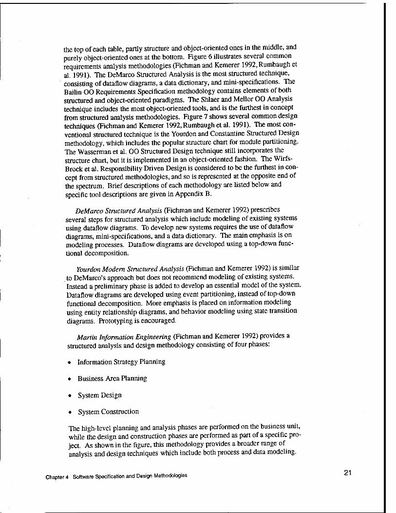
the top of each table, partly structure and object-oriented ones in the middle, and purely object-oriented ones at the bottom. Figure 6 illustrates several common requirements analysis methodologies (Fichman and Kemerer 1992,Rumbaugh et al. 1991). The DeMarco Structured Analysis is the most structured technique, consisting of dataflow diagrams, a data dictionary, and mini-specifications. The Bailin 00 Requirements Specification methodology contains elements of both structured and object-oriented paradigms. The Shlaer and Mellor 00 Analysis technique includes the most object-oriented tools, and is the furthest in concept from structured analysis methodologies. Figure 7 shows several common design techniques (Fichman and Kemerer 1992, Rumbaugh et al. 1991). The most con- ventional structured technique is the Yourdon and Constantine Structured Design methodology, which includes the popular structure chart for module partitioning. The Wasserman et al. 00 Structured Design technique still incorporates the structure chart, but it is implemented in an object-oriented fashion. The Wirfs- Brock et al. Responsibility Driven Design is considered to be the furthest in con- cept from structured methodologies, and so is represented at the opposite end of the spectrum. Brief descriptions of each methodology are listed below and specific tool descriptions are given in Appendix B.
DeMarco Structured Analysis (Fichman and Kemerer 1992) prescribes several steps for structured analysis which include modeling of existing systems using dataflow diagrams. To develop new systems requires the use of dataflow diagrams, mini-specifications, and a data dictionary. The main emphasis is on modeling processes. Dataflow diagrams are developed using a top-down func- tional decomposition.
Yourdon Modern Structured Analysis (Fichman and Kemerer 1992) is similar to DeMarco's approach but does not recommend modeling of existing systems. Instead a preliminary phase is added to develop an essential model of the system. Dataflow diagrams are developed using event partitioning, instead of top-down functional decomposition. More emphasis is placed on information modeling using entity relationship diagrams, and behavior modeling using state transition diagrams. Prototyping is encouraged.
Martin Information Engineering (Fichman and Kemerer 1992) provides a structured analysis and design methodology consisting of four phases:
• Information Strategy Planning
• Business Area Planning
• System Design
• System Construction
The high-level planning and analysis phases are performed on the business unit, while the design and construction phases are performed as part of a specific pro- ject. As shown in the figure, this methodology provides a broader range of analysis and design techniques which include both process and data modeling.
Chapter 4 Software Specification and Design Methodologies 21

More Object-
Oriented
Yourdon and Constantine Structured Design
Dataflow Diagram Hierarchy Diagram Structure Chart
Martin Information Engineering Action Diagram Dataflow Diagram Data Model Diagram Data Structure Diagram Process Decomposition Diagram Process Dependency Diagram
Wasserman et al. Object-Oriented Structured Design Object-Oriented Structure Chart
Booch Object-Oriented Design Class Diagram/Template Module Diagram/Template Object Diagram/Template Operation Template Process Diagram/Template State Transition Diagram Timing Diagram
Rumbaugh et al. Object Modeling Technique System Architecture Diagram
Wirfs-Brock et al. Responsibility Driven Design
Class Cards Class Specification Collaborations Graph Hierarchy Diagram Subsystem Card Subsystem Specification Venn Diagram
Figure 7. Common design methodologies
Bail-in Object-Oriented Requirements Specification (Fichman and Kemerer 1992) retains the structured concept of functions, although this methodology is object-oriented. However, functions are grouped together only if they operate on the same data entity. Entities have underlying states, and functions transform inputs to outputs (and have no states). Active entities are integral to the analysis phase and must therefore be considered in detail, whereas passive entities are less important and can wait until the design phase for definition. The seven step process starts by identifying entities using dataflow diagrams and an entity rela- tionship diagram. An entity dataflow diagram is constructed to show dataflows between entities, describe functions, and decompose entities into subentities. Checking for new entities, regrouping functions, and assigning entities to appropriate domains are also part of the process.
22 Chapter 4 Software Specification and Design Methodologies

Coad and Yourdon Object-Oriented Analysis (Fichman and Kemerer 1992) provides a rive step procedure for defining objects, classes, structures, hierar- chies of subject areas, attributes, and services. The process emphasizes informa- tion modeling, but also provides tools for modeling services and message con- nections. The main tools are a five layer class and object diagram which becomes more detailed as the design process progresses. The internal logic of services is represented by a service chart, which is much like a flow chart.
DeMarco Structured Analysis (Fichman and Kemerer 1992) prescribes several steps for structured analysis which include modeling of existing systems using dataflow diagrams. Development of a new system requires the use of dataflow diagrams, mini-specifications, and a data dictionary. The main emphasis is on modeling processes. Dataflow diagrams are developed using a top-down functional decomposition.
Rumbaugh Object Modeling Technique (Rumbaugh et al. 1991) is a relatively new technique based on a three model 00 view of the system.1 The object model represents the data aspect of the system and is formalized by an object diagram that represents the classes with their attributes and associations. The dynamic model incorporates the timing and control aspects of the system. Event scenarios are represented by state and event flow diagrams. The functional model shows the transformational aspects of the system using dataflow diagrams. System design involves partitioning of the application into subsystems and gen- erating a basic system architecture diagram. Object design is the last stage before coding, and where the detailed design is accomplished. Classes and their appropriate attributes are separated into modules, algorithms are designed, and software sequencing is finalized. Operations from the object model, dynamic model, and functional model are prepared for implementation in code.
Shlaer and Mellor Object-Oriented Analysis (Fichman and Kemerer 1992) provides a six step procedure to develop a three-way view of the system which includes an information model, a process model, and a state model. During this process, object life cycles, relationships, and system dynamics are also defined. Large projects benefit from the definition of distinct domains and subsystems. These domains can be: application, service, architectural, or service types. A plethora of tools are available (see Table 1) to completely describe the system.
Yourdon and Constantine Structured Design (Fichman and Kemerer 1992) provides a method for designing a system architecture based on modularity, loosely coupled modules, and high module cohesion. The structure chart is the main tool for accomplishing this. Processes are modeled using dataflow diagrams, and data structures are defined using hierarchy diagrams.
1 Interestingly, James Rumbaugh has recently been hired by Rational Software Corporation. He and fellow Rational employee Grady Booch are cooperating in the development of a new OO design approach which combines the best features of their respective methodologies.
Chapter 4 Software Specification and Design Methodologies "

Wassennan, Pircher, and Midler Object-Oriented Structured Design (Fich- man and Kemerer 1992) provides a detailed notation for describing the architec- tural design that can support either object-oriented or conventional design approaches. This high-level design does not define the internal representation of identified modules and does not provide a sequence of steps for developing the design. This process incorporates concepts from several other approaches, including: hierarchy and inheritance from object-orientation, structure charts from structured design, Ada notation for packages and tasks, and monitors from concurrent programming. Although the only tool available is a structure chart, it incorporates extended notations and symbols to support features from other suc- cessful methodology tools. Similar to the traditional structure chart, the object- oriented structure chart (OOSC) can describe modules, data parameters, and con- trol parameters. As in other object-oriented methodologies, the OOSC supports objects, classes, methods, and inheritance. Ada constructs include exception handling, generic definitions, and concurrency. Design decisions associated with the physical system can also be represented with this approach.
Booch Object-Oriented Design (Fichman and Kemerer 1992) provides an alternative to structured design and identifies four major steps that must be accomplished. During this process classes and objects along with their seman- tics and relationships must be identified. They are then implemented as part of the design. Class diagrams and templates are used to define classes and their inheritance characteristics. Object and timing diagrams define messages, visibil- ities, and threads of control. Object states and transitions are modeled with state transition diagrams. Services are defined using operation templates; module diagrams and templates define module design decisions. In multiprocessor configurations process diagrams and templates partition modules to appropriate processors.
Wirfs-Brock, Wilkerson, and Wiener Responsibility Driven Design (Fichman and Kemerer 1992) is based on the client-server approach to software design. Clients and servers represent different types of objects, and methods are imple- mented as either responsibilities or services. Contracts and collaborations between clients and servers determine each object's actions and shared data. Rather than being data-driven, which emphasizes classes and inheritance, this approach is responsibility driven, which emphasizes encapsulation and object interactions (behavior oriented). A six step approach covering two phases is recommended. The exploration phase uses class cards to 1) identify classes, 2) establish responsibilities, and 3) identify collaborations. The analysis phase defines: 4) class hierarchies using hierarchy and Venn diagrams, 5) subsystems using collaboration graphs and subsystem cards, and 6) protocols using class specifications and subsystem specifications.
When comparing structured versus object-oriented methodologies, several important issues should be considered. The main differences are based on three inherent principles of object-oriented approaches (Loy 1990):
• Encapsulation of attributes, operations, and services within objects.
24 Chapter 4 Software Specification and Design Methodologies

• Classification of object abstractions.
• Inheritance of common attributes between classes.
The primary issue is encapsulation of operations, which is based on the grouping of operations by data objects. The operations are subordinate to the data objects, whereas with functional decomposition, an integral part of struc- tured analysis, operations can access many different entities. In this approach procedures are primary, and data is secondary. One area where object-oriented strategies are lacking is in providing end-to-end processing sequences, or a view of system operations, which indicate process dependencies (Fichman and Kemerer 1992). They are either not available or cumbersome to use. Of the object-oriented methodologies, the Bailin analysis approach and the Wasserman et al. design approach are most like the traditional structured approaches. The Shlaer and Mellor analysis approach and the Wirfs-Brock et al. design approach are the most radically different from structured approaches. Object-oriented methodologies promote reusability more readily through encapsulation. They also provide a smoother transition between the analysis and design phases.
The Martin Information Engineering methodology incorporates more organi- zational and strategic business considerations than any of the other methodolo- gies, and is often used for the development of database information systems. It is data driven but not object-oriented.
Whether a specific methodology means a major change in the development organization depends on the approach currently in use. For instance, a major shift would be required for an organization to use a CASE tool based on the Wirfs-Brock et al. design approach if the Yourdon and Constantine design approach is already in use. However, the change would only be incremental if the Booch design approach is in use. This is discussed in more detail in the sec- tion on CASE tool selection criteria.
Other specification tools used in software development include the following.
• Petri Nets (Ghezzi, Jazayeri, and Mandrioli 1991, Shepard, Sibbald, and Wortley 1992) are extensions of state transition diagrams that allow for tim- ing constraints, although they still have limitations.
• Box structure (Hevner 1992, Mills 1987) is used in cleanroom software development, which is a methodology based on stringent quality control and error prevention.
• Logic and Algebraic Specifications (Ghezzi, Jazayeri, and Mandrioli 1991) are formal methods for specification of requirements.
Chapter 4 Software Specification and Design Methodologies 25

Software Domain Methodology Considerations
Consideration of which methodology to use in the development of applica- tion software should account for special techniques that may be necessary for the particular target domain. This research considers four specific software domains:
• General Purpose
• Distributed
• Real-time
• Management Information
Each domain is described and appropriate methodology capabilities are defined.
General purpose software does not have any of the special requirements of the other software domains. Any of the previously described methodologies can be used. Alternatively, several methodologies incorporating formal specifications may be used for smaller applications (Ghezzi, Jazayeri, and Man- drioli 1991). CASE tools of this type are often based on an artificial intelligence language such as Prolog, and provide extensive activity specific online help. Program correctness criteria are inherent in these tools.
Distributed system applications may be developed for multiple computers with some communications between them, or multiple processors within the same computer. Either the processing or the data may be distributed, or both. There may be a master-slave or peer-to-peer relationship between the processors, and usually there is some special processing if one of them fails. The methodol- ogy for this software domain must have constructs to support processor commun- ications, which may be synchronous or asynchronous. Subsystem constructs must also be available. The subsystem communication model from the Shlaer and Mellor analysis approach is one example of the tools available to support distributed system applications.
Real-time systems are control oriented and have a scheduler, which is respon- sible for the time constraints on the system. Scheduling may be based on dead- lines for time responses, or activity priorities. The methodology used for real- time development must support these concepts by including tools such as entity relationship diagrams, state transition diagrams, or other timing constructs (Fich- man and Kemerer 1992, Ghezzi, Jazayeri, and Mandrioli 1991). Real-time sys- tems may be embedded, which means that they typically must have interfaces to external sensors. In this case, the design methodology must adequately represent inputs of this type (especially if it is tied to code generation software). If mul- tiprocessors are involved, then tools for distributed processes must be available.
Management information systems (MIS) depend primarily on the ability to store, retrieve, and manipulate data stored in a database. The data may be
26 Chapter 4 Software Specification and Design Methodologies

analyzed and presented as a report, table, or graph. If the system is integrated with other systems (such as a manufacturing production system), then actions may be taken when the data being stored satisfies certain criteria. The software methodology used to develop such applications must be compatible with the database being used and the application objectives. As a result, database ven- dors have developed CASE tools, such as application generators, to accompany their products.
97 Chapter 4 Software Specification and Design Methodologies £-'

5 CASE Tool Considerations
Purchase of a CASE tool is a major step for most organizations, especially if automated software development techniques have not been used before. If there were only a handful of good CASE tools, then selection would be relatively easy. Unfortunately, every software productivity aid available is in some sense a CASE tool. In fact, one article lists over 400 CASE products (Lindholm 1992), but does not contain enough detail to draw any specific conclusions. This sec- tion describes some of the most important considerations and features of CASE tools to help classify currently available products.
Integrated CASE, Repositories, and MetaCASE
Integration of CASE products with other productivity tools is one of the most important challenges to be overcome in the 1990s. There are two aspects to con- sider: integration between tools offered by the same vendor, and integration between tools offered by different vendors. Products meant to be used together and offered by the same vendor have been sharing data using a common format for several years (Davis 1992, Forte and Norman 1992). Typically the data for- mat and interfacing is proprietary, and is not compatible with tools from other vendors unless some previous contractual agreement exists. Now the challenge is to provide tools which will conform to a common set of standards, allowing customers to choose a variety of tools from different vendors, and create their own customized software development environment. Open system standards currently under development will play the largest role in directing CASE tool vendors towards compatible products. This section presents the evolving frame- work for integrated CASE (ICASE) products and the different approaches ven- dors are taking to make their products compatible (Acly 1988, Brown and McDermid 1992, Chen and Norman 1992, Forte and Norman 1992,Jarke 1992, Mi and Scacchi 1992, Norman and Chen 1992,Thomas and Nejmeh 1992)
It has been recognized that the potential of CASE is limited by the difficulties of integrating tools into a common environment. One initial effort in defining an integration standard is with the development of the Information Resource Dic- tionary Systems (IRDS) by the American National Standards Institute (ANSI)
28 Chapter 5 CASE Tool Considerations

(Acly 1988). This standard attempts to define guidelines for common user inter- faces and information data passing between tools. Although a good start, this standard does not define a comprehensive ICASE framework which must include organizational considerations. Chen and Norman (Chen and Norman 1992) pro- pose such a model based on the efforts of the National Institute of Standards and Technology (NIST), the European Computer Manufacturers Association (ECMA), and Wasserman's work on CASE tool integration (Wasserman 1990). This flexible NIST/ECMA framework allows users to mix and match suitable tools that support their specific methods and is shown in Figure 8. The tools layer provides both vertical and horizontal integration. Vertical integration involves the accuracy and completeness of the information generated during all phases of the life cycle. Included are mechanisms such as forward and reverse engineering, configuration management, and requirements tracing tools. Hor- izontal integration means that the integrity of the design information remains intact when different tools and methodologies are used. Mechanisms such as a repository metamodel, integrity-checking rules, and browsing schemes are part of horizontal integration. In general, there are three forms of integration support:
• Data - provided by repository and data integration services.
• Control - provided by process management and message services.
• Presentation - provided by user interface services.
A general discussion of each of these follows, along with emerging tool stan- dards such as the Portable Common Tool Environment (PCTE). Thomas and Nejmeh give a much more detailed view of tool integration in software develop- ment environments in (Thomas and Nejmeh 1992). Further discussion of creat- ing integrated project support environments (IPSEs) as well as cameo descrip- tions of a number of IPSE products are given in (Sharon and Bell 1995).
Data Integration
Data integration can be accomplished by several different methods. It can be performed by direct transfer methods between tools, which can be difficult when many tools are involved. File based transfer is the simplest method and is quite common. The CASE Data Interchange Format (CDIF) developed by the Elec- tronic Industries Association (EIA) is a standard for file based transfer methods. A communication based transfer method is used in distributed environments and open systems. A recent innovation is the use of a repository based transfer method, which is a tightly integrated environment shared by all of the tools.
A repository provides basic services necessary for the management of the data including: entity and relationships management, configuration and version control, security, and transaction management. Additional high level services that must be provided by the repository in support of data integration include (Chen and Norman 1992):
Chapter 5 CASE Tool Considerations 29

Repository Services
Data Integration Services
A Process Management Services
User Interface Services
Message Services
Figure 8. The NIST/ECMA tool integration framework (Adapted from (Chen and Nor- man 1992, p. 19); © 1992 IEEE, reprinted by permission)
• Metamodel Service - to support the definition and management of a metamo- del such as the IRDS standard or the information model of an integrated pro- duct such as Digital Equipment Corporation's (DEC) Cohesion (Digital Equipment Corporation 1993).
• Query Service - to access information in the repository.
• Subenvironment Service - to define a view consisting of subsets of entities and operations that is consistent with the outer environment.
• Data Interchange Service - to translate data between the repository format and another format such as a file based format.
30 Chapter 5 CASE Tool Considerations

Many CASE vendors support the IRDS standard for their repositories, but many others use their own proprietary standard, which makes them difficult to integrate with other vendors' tools. Yet other repositories are based on commer- cially available databases, but these cannot easily convey the depth of semantics required by CASE applications (such as complex derivation dependencies), which means that code must convey the semantics and may have to be dupli- cated between tools (Fernstrom, Narfelt, and Ohlsson 1992). Since agreement on standards for repositories has still not been reached (Ricciuti 15 August 1992), it is likely that tool compatibility in this area will require more effort. However, IBM has provided its Repository Manager/MVS product (RM/MVS) which some suspect will eventually become a de facto standard (Davis 1992). The goal of RM/MVS is to not only provide all of the desired repository services, but to also include the ability to integrate all existing proprietary repositories. Although the product is still in its infancy, many other CASE vendors are plan- ning to provide bridges to the RM/MVS central store. CASE vendors are also providing bridges to DEC'S Common Data Dictionary/Repository (CDD/Repository). Some third party vendors are separating their CASE tools from their own proprietary repositories, so they can sell their tools to users com- mitted to other repositories.
Control Integration
Ideally control integration allows tools to activate other tools, notify other tools of specific events, and share functions. To achieve these goals the message services must provide communication from: tool-to-tool, tool-to-service, and service-to-service. The process management services can support the entire pro- cess, including project level task management, and tool invocation sequences. This allows the software engineer to concentrate on the application development rather than the specific details of the operation of each tool.
Early types of control integration included electronic mail between project team members, configuration control of the application components, and simple context management of the information and tools available to each user. A few vendors have built configurable process management CASE tools that allow an organization to customize the product to their own development process (Mi and Scacchi 1992, Shepard, Sibbald, and Wortley 1992). This is an example of Meta- CASE, in which a CASE product is provided with all of the necessary tools, but the environment may be customized to conform to the way an organization does software development, instead of the organization having to conform to the CASE environment (Forte and Norman 1992,Sorensen, Tremblay, and McAllis- ter 1988). A company may configure the CASE tool to follow a hybrid life cycle process which is unique to their software development organization. The docu- mentation of project related tasks, such as design approval meetings, may also be added to the custom development environment.
One tool interface standard that has been adopted by the ECMA is the Port- able Common Tool Environment (PCTE). The PCTE is not itself a software development environment, rather, it specifies a standardized framework around
Chapter 5 CASE Tool Considerations ^

which a development environment may be built (Bremeau 1990). An examples of this is presented in (Bremeau 1990). Although it appears to include many desirable features, PCTE does not explicitly support software engineering and has not yet achieved wide acceptance (Brown and McDermid 1992).
Presentation Integration
This level of integration requires all tools to have a common interface to the user. The first generation CASE tools of the 1970's were text based, mainframe applications accessed by terminals (Norman and Chen 1992). Since then graphi- cal user interfaces (GUI) have become an integral part of the development plat- form. A workstation for each developer which can support high resolution graphics has replaced the multiuser mainframe environment. There are several evolving de facto standards in this area: X/Motif on UNIX and DEC platforms, and Microsoft Windows and Presentation Manager on IBM PC platforms (Forte and Norman 1992). The main consideration is whether a dedicated hardware platform should be purchased for application development using the CASE tool, or whether an existing platform (such as workstations or mainframes already owned) can be used. Support for a pointing device such as a mouse is a neces- sity for modern CASE products.
Tool Integrators
A recent approach taken to provide an integrated CASE environment is through the use of tool integrators (Brown and McDermid 1992,Ricciuti 15 August 1992). These products have the ability to allow third party vendor CASE and software development tools to communicate with each other using a com- mon communications protocol to provide an integrated environment. Although not the only tool integrator available, Hewlett-Packard's SoftBench has so much third party support that it has become a de facto UNIX CASE tool integration standard (Ricciuti 15 August 1992). However, SoftBench does not include a repository since a standard for UNIX in this area has not been developed. Another product, DEC'S COHESION (Digital Equipment Corporation 1993), supposedly provides integration at all three levels: data, control, and presenta- tion. COHESION has a repository based on a proprietary protocol which is shared by all tools, including a number of third party vendor tools, to support data and control integration. The standard X Window System interface provides the presentation integration. In order to make all of the CASE tools more com- patible, agreement must be reached on standards for data repositories, and com- munications between tools.
Organizational Framework
Quite often the largest stumbling block in the adoption of a CASE tool is management's perspective on how integral it is to the organization. The NIST/ECMA model proposes a framework to help place integrated CASE in an
32 Chapter 5 CASE Tool Considerations

organizational context as shown in Figure 9 (Chen and Norman 1992). The CASE tools and services are arranged in three levels on the left side of the figure. Components at each level support the corresponding information systems (IS) development and management activities on the right side. This framework gives management a key role in the development and deployment of integrated CASE environments.
Configuration Management
Configuration management (CM) became a necessity when programming toolkit environments had to support large scale software development (Dart et al. 1987). The UNIX Programmer's Workbench included the SCCS to manage ver- sion control of modules of any type of textual information. An MRCS utility was used to track change requests, error reports, and modifications to the appli- cation being developed (Dolotta and Mashey 1976,Dolotta, Haight, and Mashey 1978). Other CM tools include Revision Control System (RCS) for UNIX and PVCS and TLIB for DOS. A CM tool that merits special mention is Rational's highly sophisticated Configuration Management and Version Control (CMVC) which is a component of their Apex development environment for Ada. It pro- vides version and change control for individual objects during development, configuration control for defining a consistent set of objects for a particular sub- system view, configuration control for defining a consistent set of views for all subsystems in a program, and support for testing, integration, and maintenance of deliverable baseline versions of a program.
With the introduction of CASE tools, documentation requirements continued to increase, and configuration management is considered an integral component of any CASE tool used for large projects. Configuration management in modern CASE tools is part of the repository services, which stores project information of all types, including documents and diagrams. Future systems may be able to handle animated images and audio (Forte and Norman 1992). Configuration management includes not only version control of all types of information, but also multi-user access control to that information. This is necessary to prevent a developer from independently modifying the same information that another developer is changing, and then destructively overwriting the same file in the repository.
Reengineering
As major applications age, they become virtually impossible to maintain. At some point these applications must be redesigned, and quite often organizations start from scratch because of inadequate documentation for the original system. Although this method may still need to be used in some cases, another combined automated/manual approach is in use. Figure 10 illustrates this three step pro- cess (McCabe and Williamson 1992).
Chapter 5 CASE Tool Considerations 33

Integrated CASE IS Development
and Management Activities
Framework for Data, Tool and Process
Integration
Corporate Standards, Methods, Tools, and
Process Models
Enterprise
Planning and Design of IS Infrastructures
Evaluation of Methods, Tools, and Processes
Software Process, Project Management,
and Measurement Techniques and Tools
Project Level Procedures, Policies,
Constraints, and Resource Allocation Decisions
Estimation and Measurement of Cost, Time, Personnel,
and Quality
Project
Management of Systems Projects
Systems Development Techniques and Tools
Elicitation, Representation, Storage, Analysis, and
Transformation of Development Information
Team and Individual
Execution of Software Processes
Figure 9. The NIST organizational framework (adapted from (Chen and Norman 1992, p. 21); © 1992 IEEE, reprinted by permission)
34 Chapter 5 CASE Tool Considerations

Reverse Original Source Code
Low-level Design Specs Engineer
Additions
Reverse Engineer
V
New or Updated Reqmts.
Reqmts. Specs
Forward Detailed Design
Generate New Code Changes Engineer
Figure 10. Steps in the reverse engineering process
Step one is to reverse engineer the application code using any of several tools available for this purpose. The main goal of this step is to capture the functional capability of the existing system in a simplified form, which can then be updated to form a new system. In essence, these automated reverse engineering tools provide the missing design level documentation which is critical to the develop- ment of a replacement system, often in the form of a specification model. If this step is skipped, then most likely some capability will be missing that was present in the original application. A number of reverse engineering tools are available as either individual tools, or as a separate component of a CASE environment suite.
Step two of the reengineering process is the revision of the specification model to include new capability and technology enhancements. By the time the application is scheduled for reengineering, there is a long list of enhancements that must be added in order to bring the application up to date. Necessary tech- nology enhancements may include the use of updated database, networking, or distributed processing functionality. This is also the time to identify redundant sections of code which may have crept into the design because of scheduling or performance constraints. These modules are properly categorized as candidates for reuse, and may be collected into a common library.
The third step is to generate structured code for the replacement application. This forward engineering process is better accomplished with integrated CASE environments available commercially. However, if the development process is not changed to conform to quality driven software changes, then maintenance of the new application will rapidly become a nightmare. Naturally, good software engineering practices that include initiating changes at the specification level and propagating them through the entire system documentation to the final code
Chapter 5 CASE Tool Considerations 35

will accomplish this (Wilde, Mathews, and Huitt 1993).
Artificial Intelligence and Reusability
Artificial intelligence in the form of knowledge based expert systems has been successfully used in several upper CASE tools (Karimi and Konsynski 1988, Luqi and Ketabchi 1988, Maiden and Sutcliffe 1992,Puncello et al. 1988, Symonds 1988). The main uses involve use of automated tools to assist the inexperienced developer in the current task, prototyping of an application at the specification level, and providing methods to reuse specifications. Each of these is discussed in the following paragraphs.
Some CASE tool implementations use automated assistants in the analysis and design phases that contain domain specific information about the application being developed and methodology specific information about the task being per- formed (Puncello et al. 1988). In this way the assistant can check the syntax and completeness of the current task, and prompt with tailored help menus for inex- perienced developers. The assistant can also use domain specific information within the knowledge base to verify the overall adequacy of analysis informa- tion.
These features are illustrated in the implementation of a process organization CASE environment developed to assist a software engineer in systematically organizing the design process of an application (Karimi and Konsynski 1988). The CASE tool uses artificial intelligence to take a flowchart representation of the software and create a series of six matrices showing detailed relationships between processes, and between modules. Timing relationships are also represented, and after some analysis, a weighted directed graph is created. The tool performs sophisticated analysis to group subgraphs decomposed from the main graph into different configurations, and gives an indication of how "good" each one is based on accepted software engineering practices. This gives the software engineer an idea of which configurations are logical choices for the final application. This CASE process organization tool not only assists the developer during the process of entering the flowchart (methodology assistance), but also performs sophisticated analysis to aid the developer in the overall appli- cation design (domain specific assistance).
One of the main goals for using automated assistants is to provide an opera- tional specification that can be "animated" as an initial prototype of the applica- tion being developed. This has been done using a formal specification language based on Prolog (Symonds 1988), and using a combination of entity relationship diagrams with an additional structural analysis language (Puncello et al. 1988). For these packages, the animated specifications in the form of rules and facts are typical of many knowledge based expert systems. The result provides a rapid prototyping environment to support an evolutionary life cycle development pro- cess.
3ß Chapter 5 CASE Tool Considerations

Naturally, support for specification development and storage in a knowledge base leads to the desire to reuse those specifications for other applications. Researchers have debated the usefulness of reusing specific code modules, since they typically incorporate details specific to that application, and must be drasti- cally changed before they can be reused (Maiden and Sutcliffe 1992). An intelli- gent CASE tool could assist the developer in selecting an appropriate high level specification that could subsequently have the code regenerated for it based on documented implementation details captured in the knowledge base of the appli- cation (Baiser 1983, Luqi and Ketabchi 1988, Maiden and Sutcliffe 1992,Symonds 1988).
Several CASE tools have been discussed with artificial intelligence as their primary thrust, but a much more integrated role for artificial intelligence is evolving in the sophisticated CASE tools of the 1990s. In fact, Balzer stated that the software development paradigm must undergo a radical shift to an automated prototyping environment designed to support more limited personnel resources (Baiser 1983). In order for these less experienced developers to be more produc- tive, the CASE tools must incorporate a knowledge based support environment that also promotes specification reuse. To accomplish this, the requirements and design phase must be formalized so that these phases can be automated. Code optimization decisions should be documented as part of the development frame- work to be implemented during code generation. Since the specifications are stored instead of specific code implementations, modules can be reused for other applications, which may have different code optimization criteria.
Hypertext
One of the goals of a comprehensive CASE tool is to provide an efficient way of navigating through the various documents and diagrams which make up a development application. A browsing or hypertext based method is often used and can be the major focus of a CASE environment (Bigelow 1988, Cybulski and Reed 1992, Mi and Scacchi 1992). Browsing can also be a supplemental feature for a programming environment, such as the Rational Environment, or a CASE environment (Forte and Norman 1992, Horowitz and Williamson 1986). By using hypertext, information fragments can be linked together to allow a user to navigate through them in a nonsequential way. In other words, a document referencing a diagram can have a dynamic link to the diagram such that it can be viewed without having to be contained in the document. This feature works especially well with windowing interfaces because they allow the document to be viewed in one window, and the diagram to be simultaneously viewed in another window. Hypertext works well when combined with a knowledge based repository to provide a powerful, user-friendly development platform that can be customized (Cybulski and Reed 1992). Hypertext capability will continue to be a valued feature in CASE tool technology, and will expand to include all aspects of multimedia (Forte and Norman 1992). Supplemental documentation will include not only graphics and animation, but also verbal annotations. Access of information in large projects will benefit from browsing technology, since accessing information only stored in a structured hierarchy can be difficult and
Chapter 5 CASE Tool Considerations 37

confusing. Search and link features make finding related information much more quickly than conventional information storage methods.
Client-Server CASE
Probably the largest shift in computing resources in the past few years has been away from large mainframe computers and towards distributed graphics based workstations in a client-server network (Pinella 1992,Ricciuti 1 April 1993). Many of these are PC based systems in use by smaller organizations. There are two major needs resulting from this shift:
• CASE tools are needed that operate in a client-server environment.
• Organizations want to develop applications that run in a client-server environment.
Many of the applications being developed are reengineered versions of main- frame applications that have become too unwieldy to use and maintain. All of the major CASE tool vendors have either released products that meet these needs or will within a very short time. These include object-oriented and database CASE vendors, as well as traditional CASE vendors. A common approach is to leave the main repository on the server computer and perform most of the software development on client computers, which are typically PCs or worksta- tions. With these new versions many of the larger CASE vendors are trying to incorporate emerging tool integration standards such as CDIF, IRDS, and PCTE.
The second need is being met in a variety of ways, one of which is the development of interface generators. These allow the GUI for an application to be painted on the screen to the specifications of the application user. The gen- erator then produces code to display and control the application GUI. This stubs in this code must then be filled in with procedures to actually accomplish the user-specified action. Examples of such generators include Screen Machine and Visual C++.
Other Considerations
The current state of CASE tool development has been presented, and still there are important features which are only just now being considered for imple- mentation. With integrated tools, more of the entire process, including strategic project management planning, can become part of the total documentation for the target application. Scheduling, organizational goals, and other high level planning techniques will be commonly included in CASE environments during the next few years (Forte and Norman 1992). Automated methods for better software metrics will be possible because all timing information and documenta- tion will be controlled through CASE (Täte, Verner, and Jeffrey 1992). This in turn will make information used in development schedules more accurate. As
QQ Chapter 5 CASE Tool Considerations

CASE tools for the distributed computing environment reach all levels of the organization, participatory design on a broader scale can be implemented. The related class of "groupware" tools is already expanding with a larger number net- work based project management and planning applications. Quite logically, this technology will also be integrated with the CASE environment (Forte and Nor- man 1992).
Standards continue to be developed to ease compatibility problems between vendor products. One such standard, POSIX, is being adopted by the major operating system vendors to provide a collection of programming interfaces for consistent access to operating system level systems. Although originally associ- ated only with UNIX, now IBM's MVS, DEC'S VMS, and Microsoft's Windows NT are moving towards open operating systems based on POSIX (Moad 1993).
39 Chapters CASE Tool Considerations Wv^

6 CASE Tool Selection Criteria
Evaluating and selecting a CASE environment can be a challenging task, especially if an organization is selecting a CASE tool for the first time. Many articles and technical reports have been written on the process of selecting software engineering tools (Dart et al. 1987), (Davis 1992), (Fersko-Weiss 1990), (Lindholm 1992), (McCabe and Williamson 1992), (Pinella 1992), (Ricciuti 15 August 1992), (Ricciuti 1 April 1993), (Ricciuti 1 March 1992), (Vessey, Jarvenpaa, and Tractinsky 1992), but good information that can be used is more difficult to find. Often the report is too specific to a situation to be help- ful generally, or it pertains to a company experience report that has been made into a "white" paper that is missing all of the important information. Chikofsky et al. describes the current state of tools assessment (Chikofsky, Martin, and Chang 1992): (© 1992 IEEE, by permission of IEEE)
It can be particularly disappointing to find a promising article on tool-selection criteria, only to realize that it reads the same if you substitute "refrigerator" for "software tool" or "CASE." We clearly need more work on what constitutes an effective assessment...
Despite the difficulties associated with the CASE tool selection task, there are resources available that can aid this process. The Software Technology Sup- port Center (STSC) at Hill Air Force Base publishes numerous reports on all aspects of software engineering and is the DoD's main facility for tool evalua- tion and classification. Information on some of the CASE tools available is given in Appendix B. The reports available from the STSC are listed in Appen- dix C. This section presents several areas of attention in CASE tool selection and provides reference points for each:
• Methodology
• Utility
• Organizational Acceptance
• Implementation Cost
40 Chapter 6 CASE Tool Selection Criteria

Methodology
Choosing the methodology to use for application development may be an easy or difficult decision, depending on the experience of the software engineers and the business organization. A thorough understanding of the target applica- tion domain is also needed. An organization that is choosing a CASE tool or environment for the first time and has not previously used any analysis/design modeling techniques may find that a conventional structured methodology is easiest to implement. Also, many of the products are available that support several methodologies. A thorough source of comparison information between specific conventional and object-oriented methodologies is given in (Fichman and Kemerer 1992).
A systematic approach for comparing different design methods is given in (Song and Osterweil 1992). They suggest creating a list of important features available from all the methods, and then comparing each method against this list. They use an evolutionary approach to develop a base framework to classify com- ponent types. Eventually this leads to a design process model which is used to select a design methodology. Another survey by (Vessey, Jarvenpaa, and Trac- tinsky 1992) evaluates how well different CASE tools support the Yourdon methodology. The tools are rated by the number and type of process, internal consistency, and hierarchical consistency checks done. They are also categor- ized as restrictive, guided, or flexible methodology companions. Restrictive tools tend to provide more checks and are better for inexperienced engineers, while flexible tools contain the fewest checks and are preferred by experienced engineers.
Utility
Evaluating a CASE tool on its ease of use is usually done by an organization before adopting it. However, quite often the evaluation is limited, and the final decision is based only on look and feel attributes or documentation, instead of on how well the tool supports a specific methodology (Chikofsky, Martin, and Chang 1992). The IEEE has published standard 1209-1992, "IEEE Recom- mended Practice for the Evaluation and Selection of CASE Tools" to assist organizations in this difficult process. Another evaluation process has been developed by the Westinghouse Software Tools Evaluation Committee (STEC) in conjunction with the SEI at Carnegie Mellon (Mosley 1992). Their evaluation criteria is based on a five step process:
• Classification - Information is gathered.
• Brief Evaluation - Identifies how well the tool performs. If it performs well enough, then the next step is performed.
• Quantitative Assessment - A detailed evaluation based on 170 to 240 weighted questions done by three evaluators.
Chapter 6 CASE Tool Selection Criteria 41

• Tailored Summary - The results are scored and the critical information is extracted as to what the scores represent.
• Consultation Service - The evaluator takes the results and recommends the top tools to potential users.
The STEC has classified more than 500 tools, briefly evaluated 25%, and quantitatively assessed the best 10%. For them it has proven to be an effective assessment scheme.
A number of surveys and studies have been performed on the capabilities of CASE tools for different operating systems (Fersko-Weiss 1990,Ricciuti 1 March 1992, The 1992, Vessey, Jarvenpaa, and Tractinsky 1992). Although these resources should not be used exclusively to evaluate CASE tools, they can help provide insight and familiarity with the various options available.
Organizational Acceptance
Ultimately how dedicated the organization is to the adoption of CASE tech- nology to improve their software engineering environment determines how suc- cessful the effort will be. All too often the adjustment is considered just a matter of purchasing the tools (Huff 1992). However, one study shows that after one year 70% of CASE tools purchased have never been used (Kemerer 1992). Yet, with the increasing complexity of software development tasks, it is obvious that more organizations will need to automate the process. Why are so many of these businesses unsuccessful in the incorporation of CASE technology? A large part of the answer lies in the misinterpretation of the learning curve required for software engineers and its affect on productivity (Kemerer 1992). One reason why the integration fails is that companies often try to use a CASE tool for the first time on a project that is behind schedule in hopes that the tool will provide a "miracle cure." What management optimistically expects is a short time period during the introduction period when no gains in productivity are realized fol- lowed by a rise that eventually levels off. What actually happens is that there is a period of time varying between six months and two years when productivity actually decreases (and subsequently project cost increases) before an improved performance of between 30 and 50% is gradually realized (Kemerer 1992). This is because integrated CASE tools cover the entire life cycle, and therefore require more time to learn. Figure 11 illustrates this relationship (Kemerer 1992). Naturally, an organization that has never used modeling design or analysis methods will require much more time to master a CASE tool than one that is simply upgrading to a more sophisticated tool. In order for CASE tool adoption to be successful, all levels of the business must understand the invest- ment in human resources that must be made to master the CASE environment. For some companies this may actually require a cultural change that must be not just supported, but encouraged by management.
42 Chapter 6 CASE Tool Selection Criteria

A Relative Performance
Improved Performance
Time >•
Figure 11. The learning curve (adapted from (Kemerer 1992, p. 24); © 1992 IEEE, reprinted by permission)
Implementation Cost
Companies adopting a CASE tool for the first time may not realize the total cost required. Huff provides a good summary of the total CASE tool costs which is derived from an SEI CASE adoption Workshop (Huff 1992). The article identifies several phases for an adoption life cycle:
• Awareness and analysis
• Commitment and acquisition
• Implementation
• Operations
All of the objectives, comparisons, and economic assessments are performed during the awareness and analysis phase. A tool champion is usually required to initiate an analysis of potential CASE tools and methodologies, and to start edu- cating management on the costs involved. All of the issues including hardware platform, operating system, methodology, and particular CASE tool are deter- mined during this phase. During the commitment and acquisition stage, manage- ment actually commits to an implementation proposal, and necessary resources are purchased. A pilot study may be conducted to test the success of the adop- tion strategy on a smaller scale. Once the plan is proven, the remaining resources are purchased and installed. Software engineers using the tools must be trained on their use, and people at all levels of the organization affected must
Chapter 6 CASE Tool Selection Criteria 43

also obtain appropriate education. The biggest challenge is often in the opera- tions stage of CASE tool adoption. The technical and organizational changes brought about in previous stages must be maintained into the future in order for CASE tools to succeed. It has been reported that two years after implementation, 70% of the CASE tools are no longer used, and only 10% of those still in use are used properly (Huff 1992). Education and management support continue to be critical to maintaining the proper level of software development expertise. Only then can the CASE adoption strategy be considered successful.
CASE Tool Vendor Overview
A comprehensive listing of over 400 CASE tools available on the market today can be found in (Lindholm 1992). Specific references to vendor tools were avoided in the text to avoid biasing potential purchasers, except where de facto standards are emerging based on specific vendor tools. This paper is meant to be a starting point for CASE tool selection, and the vendors described for each category in Appendix B are only a cross-section.
The CASE products are listed alphabetically by vendor instead of by name because often there is not just one product represented, but a suite of tools. It is impossible to put each vendor in only one category since the capabilities pro- vided overlap considerably. However, a general category listing is given at the top of each description to separate tool integrators from CASE tools, etc. The primary supported operating system platforms include UNIX, DEC VMS, PC DOS/Windows, and Macintosh. The product types listed in Appendix B span the following categories:
• Database CASE
• Upper CASE
• Integrated CASE
• Object-oriented CASE
• MetaCASE
• Tool Integrators
44 Chapter 6 CASE Tool Selection Criteria

7 Conclusions
Because the amount of CASE tool information available in the literature can be overwhelming, it is important to develop a plan for the selection and imple- mentation of a set of CASE tools. Being able to identify the expectations and requirements of an integrated software engineering environment will make the process more manageable. Certainly the availability of using tool integrators that can fashion an environment out of individual vendor tools is a viable alter- native to the purchase of the entire product from one vendor. Emerging stan- dards will continue to improve the compatibility between tools. Many of the products available can be purchased as a basic configuration for less cost, and then scaled up as requirements change and more sophistication is desired. With the spectrum of choices available, a custom configuration to fit every organiza- tion is possible. The process begins with a careful analysis of the organizational and engineering practices, and the desire to automate the software development life cycle process.
Chapter 7 Conclusions 45

References
Acly, E. (March 1988). "Looking beyond CASE," IEEE Software, 39-43.
Acly states that in order for CASE tools to evolve, they must address the user's needs for stability and integration. The total solution is to provide a Computer-aided development and maintenance environment (CADME), which is integrated and stable. If standard interfaces are developed, then CADME tools can interface with each other, with third and fourth generation languages, and different database architectures. The author presents two different architectures which address these needs: the three-schema architec- ture and the information-resource dictionary system (IRDS) architecture.
Baiser, R. (November 1983). "Software technology in the 1990's: using a new paradigm," Computer, 38-45.
This article proposes that a radical approach to software development will need to be implemented in order to make increasingly complex software maintainable. This approach should be based on an automated software para- digm designed to support more limited personnel resources. This knowledge-based environment would be integral to every phase of develop- ment, by recording, analyzing, and performing different activities. Require- ment specifications would be formally entered, and the prototype executed to determine if the behavior of the system is as expected. Code optimization strategies would also be entered such that the environment would perform the specified optimizations on the generated code. These activities would reduce the testing involved at later stages of development, and the clerical errors introduced in the current labor-intensive development paradigm. The target software would be maintainable over a much longer lifetime and at a lower cost
Barbacci, M. R., Doubleday, D., Weinstock, C. B., and Lichota, R. W. (Sep- tember 1991). "Durra: an integrated approach to software specification, modeling, and rapid prototyping," SEI Technical Report CMU/SEI-91-TR- 21.
Software specification, modeling, and prototyping activities are often per- formed at different stages in a software development project by individuals
46 References

who use different specialized notations. The need to manually interpret and transform information passed between stages can significantly decrease pro- ductivity and can serve as a potential source of error. Durra is a nonpro- cedural language designed to support the development of distributed applica- tions consisting of multiple, concurrent, large-grained tasks executing in a heterogeneous network. Durra provides a framework through which one can specify the structure of an application in conjunction with its behavior, tim- ing, and implementation dependencies. These specifications may be vali- dated by passing behavioral and timing information associated with each Durra task description to a run-time interpreter. Similarly, software proto- types may be constructed by directing this information to a suitable source code generator. We have already developed an interpreter and source code translator for a language-based on simple timing expressions. We are presently constructing a source code generator for a more complex language defined by SMARTS (the Specification Methodology for Adaptive Real-Time systems developed by Hughes Aircraft Company). (From Barbacci et al. 1991, © 1991 SEI, reprinted by permission).
Baxter, I.D. (April 1992). "Design maintenance systems," Communications of the ACM 35(4), 73-89.
Four major projects are described that failed because they could not be suc- cessfully maintained. A transformation control language model is described which provides mechanisms for maintenance. The method incorporates design maintenance deltas which are iteratively transformed into code.
Bigelow, J. (March 1988). "Hypertext and CASE," IEEE Software, 23-27.
Tektronix has developed a comprehensive CASE environment based on a hypertext data model in which to develop software applications. The tool uses a layered architecture which can be organized to include all of the specification, design, and user documentation as well as the actual code for a project. Bigelow describes the context concept, which allows partitioning modules into different versions for configuration control, and local user development workspaces. Other features of the hypertext CASE tool allow it to be integrated with other development tools to make the environment more complete.
Boehm, B. W. (May 1988). "A spiral model of software development and enhancement," Computer, 61-72.
The author introduces a new spiral life cycle process model for software development which is based on project risk management. This is a metamo- del because it accommodates other life cycle models within its structure. The existing process models are described along with their disadvantages. The details of the new spiral model are presented and a systematic approach for using it to manage risk is outlined. The author finishes by describing areas for improvement of the new model.
Booch, G. (1994). Software engineering with Ada. Benjamin/Cummings Pub-
References 47

lishing Company, Menlo Park.
This is a highly readable book which is both an advanced introduction to Ada as well as an introduction to software engineering using an object-oriented approach for design and Ada as the coding vehicle. Data structures, algo- rithms and control, Ada packages, and eal-time processing are all addressed. Of particular interest is the last section on systems development which covers the software life cycle and programming in the large.
Bremeau, C. (1990). "The PCTE contribution to Ada programming support environments (APSE)." Software engineering environments: international workshop on environments. F. Long, ed., Lecture notes in computer science, 467,, 151-166.
The PCTE is not, in and of itself, a software development environment. Rather, it may be viewed as a framework, or perhaps a kernel APSE (KAPSE), to support such an environment. The distributed architecture of the PCTE allows networked workstations to share software, data, and other resources. The PCTE includes an Object Management System (OMS). This OMS is based on an entity-relationship model and serves as the interface to the PCTE's database; this database may itself be distributed. The OMS is perhaps the PCTE's most significant contribution to APSEs. It allows representation of Ada libraries and compilation units and specification of objects, links, and attributes. Additionally it provides support for composite objects, software versions, and multiple inheritance.
Brown, A. W., Earl, A. N., and McDermid, J. A. (1992). Software engineering environments: automated support for software engineering. McGraw-Hill, London.
This book provides an introduction to software engineering environments (SEEs) including a historical perspective on their evolution. The reference model for frameworks of SEEs is presented, followed by descriptions of PCTE, Hewlett-Packard's SoftBench, Digital's Case Interface Services, and IBM's AD/Cycle. The final three chapters review reported experience with SEEs, discuss the concept of integration, and summarize possible future directions for SEEs.
Brown, A. W. and McDermid, J. A. (March 1992). "Learning from IPSE's mis- takes," IEEE Software, 23-28.
This article describes important issues of tool integration from an open sys- tems viewpoint The authors contend that standards such as the PCTE focus too much attention on integration at the syntactic or lexical levels for Integrated Project-Support Environments (IPSEs), instead of at the higher semantic and method levels. The shortcomings of IPSEs are examined in terms of five different levels of integration: carrier, lexical, syntactic, seman- tic, and method. The carrier level is the most basic type of integration, requiring only a common file format or byte stream. The method level is the highest because tools integrated at this level fulfill specific roles in the development process. The tools already agree on common data structures
48 References

(syntactic level) and the operations on them (semantic level). The authors believe that efforts should be redirected to achieve the method level integra- tion for IPSEs.
Carr, M. J., Konda, S. L., Monarch, I., Ulrich, F. C, and Walker, C. F. (June 1993). "Taxonomy-based risk identification," SEI technical report CMU/SEI-93-TR-6.
This report describes a method for facilitating the systematic and repeatable identification of risks associated with the development of a software- dependent project This method, derived from published literature and previ- ous experience in developing software, was tested in active government- funded defense and civilian software development projects for both its use- fulness and for improving the method itself. Results of the field tests encouraged the claim that the described method is useful, usable, and efficient. The report concludes with some macro-level lessons learned from the field tests and a brief overview of future work in establishing risk management on a firm footing in software development projects. (From Carr et al. 1993, © 1993 SEI, reprinted by permission).
Chen, M. and Norman, R. J. (March 1992). "A framework for integrated CASE," IEEE Software, 18-22..
Difficulties have been encountered in the development of integrated CASE products. The authors introduce a development framework based on NIST, ECMA, and Wasserman reference models. The technical framework describes three forms of integration: data, control, and presentation. The data integration must define how data can be passed between tools, and often becomes part of repository requirements. Metamodels are described as a means of achieving a higher level of data integration. Other elements in the model are plug-in tools, process management services, and user interface ser- vices. An organizational model is presented which describes planning and design of IS infrastructures, project management, and software process exe- cution.
Chikofsky, E. J., Martin, D. E., and Chang, H. (May 1992). "Assessing the state of tools assessment," IEEE Software, 18-21.
Tools assessment is becoming more of a concern because of the vast number and complexity of software engineering tools that are available on the market. CASE tools especially are quite often evaluated based on the suc- cess of a specific project Since the entire process is becoming automated, proper assessment of tools before they are purchased may ultimately deter- mine how successful a project may be. The authors stress that more attention is needed in this area.
Chikofsky, E. and Rubenstein, B. (March 1988). "CASE: reliability engineer- ing for information systems," IEEE Software, 11-16.
This is an introductory article about what CASE tools are, how they can improve productivity in the software development life cycle, and what
References 49

specific components they can have.
Connell, J. L. and Shafer, L.B. (1989). Structured rapid prototyping, an evolu- tionary approach to software development. Yourdon Press, Englewood Cliffs.
Cureton, B. (March 1988). "The future of UNIX in the CASE renaissance," IEEE Software, 18-22.
Cureton provides his views on CASE development for the UNIX operating system environment. Because UNIX is open, extensible, and widely used, CASE tools must be developed for it in order for them to be successful. Cureton also sees the areas of windows development, databases, and network communications as being the future areas of development for UNIX and CASE.
Cybulski, J. L. and Reed, K. (March 1992). IEEE Software, 62-68.
A specific hypertext environment, called HyperCASE, has been developed to integrate a collection of CASE tools into a broader information management and presentation scheme, This product includes such features as: authoring tools, a reporting system, and specification animation. A knowledge base implemented using the INGRES database is an integral part of the system. ER diagrams and hierarchy diagrams are two specification tools used. The main architecture includes HyperEdit, consisting of an interface manager and authoring tools, HyperBase, consisting of CASE tools and project base tools, and HyperDict, consisting of query and reporting systems. The system is a marriage between a hypertext-based user interface and a document-based knowledge repository. To date, the authors have focused primarily on front- end issues, so they have not added ability for code generation or support for specific methodologies.
Dart, S., Ellison, R., Feiler, P., and Habermann, A. (November 1987). "Software development environments," Computer, 18-28.
The authors describe the four major categories of software development environments: language-centered, structure-oriented, toolkit, and method- based. They discuss the features and limitations of each, using specific examples of tools currently available. They conclude that the major issues that need to be addressed before these environments can be made more integrated are data management and project management.
Davis, D. (March 11,1992). "Safe deposit for enterprise data," Datamation, 67-70.
Repositories are becoming an integral part of the CASE tool set, and their main features include: version control, access control, documentation sup- port, organization of all aspects of the application, and potential for code reuse. Discussion of repository-based products developed by IBM, DEC, UNISYS, and others is also provided.
50 References

Digital Equipment Corporation. (1993). COHESION environment for CASE: realizing competitive advantages from software engineering. Digital Equip- ment Corporation.
This handbook presents Digital Equipment Corporation's (DEC) vision for COHESION, DEC'S integrated CASE environment. COHESION includes products and services which span the software development life cycle. These include tools for embedded systems, information systems maintenance and reengineering, rapid application development, as well as third-part CASE tools. The COHESION repository, CDD/Repository, is also described.
Dolotta, T. A. and Mashey, J. R. (1976). "An introduction to the Programmer's Workbench," Proceedings - Second International Conference on Software Engineering, 164-168.
The Programmer's Workbench (PWB) is introduced in terms of the general concept, disadvantages, advantages, and facilities provided. The Remote Job Entry, Source Code Control System, Modification Request Control System, document preparation, and test drivers are briefly described. A short history of the PWB is also included.
Dolotta, T. A, Haight, R. C, and Mashey, J. R. (July-August 1978). "UNK time-sharing system: the Programmer's Workbench," Tlie Bell System Techn- ical Journal 57(6), 2177-2200.
The Programmer's Workbench (PWB/UNIX) is a collection of utilities designed to support large software development projects. Although one com- puter system can be used for the software development and production, PWB/UNIX was intended to be used on a separate dedicated development computer system with a separate target production system. The background and design approach are described and the facilities for the Remote Job Entry, Source Code Control System, Text Processing and document prepara- tion, and Test Drivers are presented. Modifications to the UNIX operating system were carefully considered in terms of reliability, operations, user environment, and shell extensions, before being implemented.
Fernstrom, C, Narfelt, K., and Ohlsson, L. (March 1992). "Software factory principles, architecture, and experiments," IEEE Software, 38-44.
Making CASE tools flexible and configurable is the main goal of this article. The concept of a software factory is introduced as a way to achieve this. One implementation is the Eureka Software Factory project which has a communication-centered CASE architecture. This project includes 13 Euro- pean vendors who each produce a component of the project. Like a conven- tional factory, each vendor focuses on the niche product they do best, and factory vendors are responsible for putting the pieces together to form a spe- cially configured, integrated CASE environment. Each component plugs into a software bus, which provides the seamless integration appearance to the user. The concept is based on an application model, rather than a repository- based model, so that specific Schemas can be defined. The application layer is placed on top of the data model, and that way the implementation of an
References 51

object is transparent to the application using it. Advocates believe that build- ing tools in this manner reduces their interdependence. Two generator tools have been developed to automate the creation of user interfaces. The project has created several experimental environments, and is now at the stage of actually building environments for the needs of specific customer organiza- tions.
Fersko-Weiss, H. (January 30,1990). "CASE tools for designing your applica- tions," PC Magazine, 213-251.
The author describes the capabilities of the PC-based CASE tools available on the market. A brief outline of the types of methodologies supported is also given. The CASE products compared are: Analyst/Designer Toolkit by Your- don, Auto-mate Plus by LBMS, DesignAid by Nastec, Excelerator by Index Technology, EW Workstation products by Knowledge Ware, POSE by Com- puter Systems Advisors, ProKit Workbench by McDonnell Douglas, Team- work by Cadre Technologies, Visible Analyst Workbench by Visible Systems Corporation, and vsDesigner by Visual Software. Visible Analyst Work- bench was picked as the best low priced product, but higher priced products should be chosen based on specific needs.
Fichman, R. G. and Kemerer, C. F. (October 1992). "Object-oriented and con- ventional analysis and design methodologies," Computer, 22-39.
This article presents and compares several popular conventional and object- oriented methodologies for the analysis and design phases of software development. The analysis methodologies are: DeMarco Structured Analysis, Yourdon Modern Structured Analysis, Martin Information Engineering, Bailin 00 Requirements Specification, Coad and Yourdon 00 Analysis, and Shlaer and Mellor 00 Analysis. The design methodologies are: Yourdon and Constantine Structured Design, Martin Information Engineering, Wasserman et al. 00 Structured Design, Booch 00 Design, and Wirfs-Brock et al. Responsibility-Driven Design. The different components available in each methodology and their relative weaknesses are presented.
Forte, G. and Norman, R. J. (April 1992). "A self-assessment by the software engineering community," Communications of the ACM 35(4), 28-32.
The findings of the last International Workshop on CASE are summarized. They represent a cross section of opinions of over 200 experts about the state of developing CASE technology. The article represents a self-assessment of how well the methodologies and tools are bringing software engineering closer to a respectable engineering discipline.
Georges, M. and Koemmerer, C. (1990). "Use and extension of PCTE: the SPMMS information system." Software engineering environments: interna- tional worksiiop on environments. F Long, ed., Lecture notes in computer science, 467,, 272-282.
The objective of the Software Production and Maintenance Management Support (SPMMS) was to provide a project management support system
52 References

which could fit into various environments and accommodate a wide variety of management practices. The SPMMS is implemented on top of both the Emeraude and Olivetti versions of PCTE. Conventional database systems could not provide the support for management practices required in a software development project. SPMMS filled this gap in functionality by providing object inheritance, user-defined rules and triggers for information updating, and customization governed by a conceptual database schema. An integrated Lisp interpreter was instrumental in providing these features.
Ghezzi, C, Jazayeri, M., and Mandrioli, D. (1991). Fundamentals of software engineering. Prentice Hall, Englewood Cliffs.
Hevner, A. R. (March 1992). "Integrated CASE for cleanroom development," IEEE Software, 69-76.
Complex systems are solved more efficiently with integrated CASE products based on cleanroom development techniques. The CASE product featured in this article uses a formal object-oriented methodology that covers the entire life cycle, a central repository, and an integrated set of automated tools. The box structure analysis and design tool uses a black box component to describe system requirements in terms of a mathematical function. A state box component provides information about the systems state, and a clear box component describes system procedures. A usage hierarchy represents the relationship between different boxes. This methodology can be used to design systems of any size and complexity. Several successful IBM clean- room projects are presented.
Horowitz, E. and Williamson, R. (November 1986). "SODOS: a software docu- mentation support environment - its use," IEEE transactions on software engineering 12(11), 1076-1087.
This paper describes a computerized environment, SODOS (Software Docu- mentation Support), which supports the definition and manipulation of docu- ments used in developing software. An object oriented environment is used as a basis for the SODOS interface. SODOS is built around a Software Life Cycle (SLC) Model that structures all access to the documents stored in the environment. One advantage of this model is that it supports software independent of any methodology that the developers may be using. The main advantage of the system is that it permits traceability through each phase of the Life Cycle, thus facilitating the test and maintenance phases. Finally the effort involved in learning and using SODOS is simplified due to a sophisti- cated user-friendly interface. (From Horowitz and Williamson 1986, © 1986 IEEE, by permission of IEEE).
Huff, C. C. (April 1992). "Elements of a realistic CASE tool adoption budget," Communications of the ACM 35(4), 45-54.
Companies adopting a CASE tool for the first time may not realize the total cost required. Huff provides a good summary of the total CASE tool costs which is derived from an SEI CASE adoption Workshop. The article identifies several phases for an adoption life cycle: awareness and analysis,
References 53

commitment and acquisition, implementation, and operations. All of the objectives, comparisons, and economic assessments are performed during the awareness and analysis phase. A tool champion is usually required to initiate an analysis of potential CASE tools and methodologies, and to start educating management on the costs involved. All of the issues including hardware plat- form, operating system, methodology, and particular CASE tool are deter- mined during this phase. During the commitment and acquisition stage, management actually commits to an implementation proposal, and necessary resources are purchased. A pilot study may be conducted to test the success of the adoption strategy on a smaller scale. Once the plan is proven, the remaining resources are purchased and installed. Software engineers using the tools must be trained on their use, and people at all levels of the organiza- tion affected must also obtain appropriate education.
Jarke.M. (March, 1992). "Strategies for integrating CASE environments," IEEE Software, 54-61.
The problem of integrating CASE environments for data intensive systems is addressed with the introduction of the Development Assistance for Integrated Database Applications (DAIDA) environment. This framework incorporates a process model to achieve a conceptual level of integration with the aid of knowledge-based mapping assistants. This environment also uses hypertext features to navigate through information and includes requirements anima- tion. Validation can be done through the use of prototyping in Prolog. Although the spiral model is currently supported by the knowledge-based assistants, other software life cycles can be supported.
Jones, M. C. and Arnett, K. P. (May 1,1992). "CASE use is growing, but in surprising ways," Datamation, 108-109.
A brief description is given on the main uses of CASE tools. Surveys are described which show that CASE tools are used, but not to their full extent. The main uses for CASE are program management, data dictionary manage- ment, documentation, prototyping, and graphics capabilities.
Karimi, J. and Konsynski, B. (February 1988). "An automated software design assistant," IEEE transactions on software engineering 14(2), 194-210.
An automated software design assistant was implemented as part of a long term project, with the objective of applying the computer-aided technique to the tools in a software engineering environment. A set of quantitative meas- ures are derived based on the degree to which a particular design satisfied the attributes associated with a structured software design. The measures are then used as a set of decision rules for a computer-aided methodology for structured design. The feasibility of the approach is also demonstrated by a case study using a small application system design problem. (From Karimi and Konsynski 1988, © 1988 IEEE, by permission of IEEE).
Kemerer, C. F. (May 1992). "How the learning curve affects CASE tool adop- tion," IEEE Software, 23-28.
54 References

One of the main reasons why organizations buy CASE tools and then leave them on the shelf is because they misjudge the amount of time it takes to properly train software engineers. What actually happens when a new CASE tool is adopted is that there is a period of time from six months to two years when productivity will actually decrease (and project costs increase) while the engineers learn to effectively apply CASE technology to application pro- jects. The author presents the issues involved in adapting a learning curve model to the integrated CASE problem. These issues include knowledge- work sensitivities, task diversity, the amount of learning required for the tool versus the underlying methodology, and implementation issues.
Lempp, P. and Lauber, R. (June 1988). "What productivity increases to expect from a CASE environment: results of a user survey," Productivity: progress, prospects, and payoff, 13-19.
The authors conducted a survey of the CASE environment EPPOS to deter- mine how much productivity improved using different features of the tool. The group of projects studied was quite small, 22 projects at 14 different companies. Because the range of the study covered five years, the features for code generation and the conceptual design phase were not available in the tool. Consequently productivity increases were not improved in these areas. The greatest increases were in the area of project management and control. This task was considered to be much easier with the CASE tool. Although more time was spent in the earlier specification and analysis phases, docu- mentation of the system was much improved, allowing almost 75% to be gen- erated automatically by the EPOS environment. The incidence of specification and design errors detected in the later phases of development was also improved by 70%. The result was overall improvement in quality control of the final product. The cost associated with a project tended to be higher during the initial stages of development due to the increased documen- tation efforts, but the maintenance phase cost was reduced by almost 70%, with a decrease of 9% over the entire development effort. The improvements to the development of target software using EPOS is considered to be evolu- tionary rather than revolutionary. If additional support for the coding and design phases were implemented in the tool, the cost decrease is expected to be 30%. Although these improvements are not dramatic, the main benefits are in the area of quality, in terms of improved documentation done automati- cally, and better management and visibility of programs assets.
Lindholm, E. (March 1,1992). "A world of CASE tools," Datamation, 75-81.
This article presents over 400 CASE products for a variety of operating sys- tem platforms. The information is listed by company name, product, product type, and platform. No addresses or phone numbers are given.
Long, F. ed. (1992). ADA yearbook 1992. Chapman and Hall, London.
This is truly a yearbook, providing general information on Ada as well as specific descriptions of corporations and groups with an interest in the furth- erance of Ada. Lists of Ada suppliers and validated Ada compilers and reports on the status of Ada 9X, and Ada bindings to POSIX, SQL, and X are
References 55

included. Software engineering issues relevant to Ada are also discussed.
Loy.P. H. (January 1990). "A comparison of object-oriented and structured development methodologies," ACM SIGSoft software engineering notes 15(1), 44-48.
The author describes what is meant by object-oriented development and why there is disagreement among researchers about which languages and tech- niques are included. The history of 00 development is presented and con- cise definitions are given. A comparison between 00 methods and structured methods is also described, with emphasis on eventual integration of tech- niques from both methodologies that support fundamental principles.
Luqi, and Ketabchi, M. (March 1988). "A computer-aided prototyping sys- tem," IEEE Software, 66-72.
This article describes a prototyping system which executes specifications via reusable components. The traditional software life cycle is replaced by one based on two phases: rapid prototyping and automatic program generation. The developer uses dataflow diagrams that allow nonprocedural control infor- mation to be added, providing a complete specification for a component. Reusable components stored in a specification library are used to execute the prototype. Individual components are stored in the library for the VMS and UNIX operating systems, with implementation language support for Ada and C. Extensive software tools are available to help the developer with informa- tion entry and prototype execution analysis.
Maiden, N. A. and Sutcliffe, A.G. (April, 1992). "Exploiting reusable specifications through analogy,'' Communications of the ACM 35(4), 55-64.
The possibility of reusing specifications by analogy is investigated using a knowledge-based set of tools. Instead of trying to reuse actual software code, the authors suggest that a more general specification for a given function could be more easily reused for another application. Recognition and selec- tion of potential candidates for reuse is accomplished using an analogy approach. An environment that supports this ability employs an Intelligent Reuse Advisor, Problem Identifier, Analogy Engine, and Specification Advi- sor. The authors present the results of several case studies using their approach and support environment. Inexperienced software engineers tended to copy and use the existing specifications without really understanding how they should be modified to work in a new application. Experienced software engineers were much more successful in correctly reusing specifications in a new application, but still had some trouble completely understanding the entire analogy being applied. The authors suggest that CASE tools can and should support this process with knowledge-based assistance.
McCabe, T J. and Williamson, E. S. (April 15,1992). "Tips on reengineering redundant software," Datamation, 71-74.
Reengineering software is becoming a major activity of IS organizations. The authors present a three step approach to effectively reengineer major
56 References

applications. The first step involves using an automated reverse engineering tool to convert existing code into process logic that usually includes diagrams. In the second step, the specification model is updated to include new capabilities, eliminate redundancy, and take advantage of new techno- logical advances. The third step is to forward engineer the new design to code. Using CASE tools during these steps can make the new code easier to maintain by properly incorporating changes at the specification level, and then propagating them through to the code level. To successfully maintain the software, the organization must make the transition from schedule driven software to quality driven software. The authors discuss several vendors who provide reengineering tools and discuss their areas of use.
Mi, P. and Scacchi, W. (March 1992). "Process integration in CASE environ- ments,' ' IEEE Software, 45-53.
Process integration is a higher level of integration than tool or object integra- tion and explicitly defines the development process. In order for tools to be effective at this level, they must make the execution process flexible and reusable. Software managers have the ability to monitor project progression, manage workspaces, and control tool invocations. Process integration allows an organization to customize the life cycle model. An experiment at the University of Southern California to make the integrated Softman CASE pro- duct process driven is described.
Mills, H. D. (September 1987). "Cleanroom software engineering," IEEE Software, 19-25.
Software quality can be built into an application using a process similar in concept to the manufacture of computer chips. This cleanroom methodology is based on statistical quality control which stresses error prevention rather than error detection. A combination of formal design methods and mathemat- ics based verification resulted in finding over 90% of product defects before execution. The functional verification method uses ordinary mathematical reasoning about sets and functions to replace debugging.
Moad, J. (April 1,1993). "POSIX cracks the lock on MVS," Datamation, 47- 50.
POSIX represents a collection of standard programming interfaces which allow access to operating system services. These standards are under development through the IEEE, and apply to any operating system. IBM is taking steps to open its MVS operating system to comply with POSIX, which will allow applications greater portability and interoperability between UNIX and other systems. Many agencies, including the military, are taking steps to make compliance with POSIX an important part of application development.
Mosley, V. (May 1992). "How to assess tools efficiently and quantitatively," IEEE Software, 29-32.
An evaluation process for software tools has been developed by the Westing- house Software Tools Evaluation Committee (STEC) in conjunction with the
References 57

Software Engineering Institute (SEI) at Carnegie Mellon. Their evaluation criteria is based on a five step process of classification, brief evaluation, quantitative assessment, tailored summary, and consultation service. The STEC has classified more than 500 tools, briefly evaluated 25%, and quanti- tatively assessed the best 10%. For them it has proven to be an effective assessment scheme.
Norman, R. J. and Chen, M. (March 1992). "Working together to integrate CASE," IEEE Software, 12-16.
This article introduces an entire issue of IEEE Software dedicated to the issues involved with integrated CASE. The authors present an evolution of CASE, focusing on tools, methods, and applications. This started around 1970 with structured programming methods on batch transaction systems using high level compilers. By 1995 integrated methods, systems, and CASE will be able to develop applications in a distributed environment.
Oram, A. and Talbot, S. (1991). Managing projects with make. O'Reilly and Associates, Sebastopol, California.
This book provides an introduction to and a complete reference on make. Interaction with the shell, writing macros, suffix rules, project management, special targets, and troubleshooting are all covered. Two appendices cover popular extensions to make and differences between various versions.
Page-Jones, M. (1980). The practical guide to structured systems design. Your- don Press, Englewood Cliffs.
Penedo, M. H. and Stuckle, E. D. (1990). "TRW's SEE Saga." Software engineering environments: international workshop on environments. F. Long, ed„ Lecture notes in computer science, 467,, 25-55.
Software productivity has become a concern for all defense contractors. TRW, cited as the second largest software producer in the world, is no excep- tion. This paper describes how TRW addressed this issue through a number of internal projects, including their Software Productivity System, the Project Master Data Base, the Quantum Leap Initial Operating Capability, and the TRW Integrated Support Environment. The architecture of these systems is described, and future work at TRW is discussed.
Pinella,P. (March 1,1992). "The race for client/server CASE," Datamation, 51-54.
The author describes the issues involved with client/server CASE tools across multiple hardware and operating system platforms. Not only must the tool be able to be developed on distributed platforms, but must also be able to gen- erate applications that run on these platforms. A discussion of UNIX net- working support versus PC networking support is presented.
Puncello, P., Torrigiani, P., Pietri, F, Burlon, R., Cardile, B., and Conti, M. (March 1988). "APSIS: a knowledge-based CASE environment," IEEE
eg References

Software, 58-65.
This paper describes a project that seeks to improve the quality and produc- tivity of the first phases of the life cycle by combining artificial intelligence with software engineering techniques. The Application Software Prototype Implementation System (APSIS) is based on the evolutionary life cycle and uses a logic-based formal specification language. It consists of four knowledge-based assistants to support the requirements analysis and design stages of the life cycle. An analysis and a design assistant each provide methodical and domain specific user support during development. The proto- type assistant translates the informal specifications created by the analysis assistant into executable Prolog, thereby allowing animation of the opera- tional specifications. The reuse assistant is being developed to support module reuse efforts. The underlying knowledge base representation is in the form of three integrated semantic networks and production systems.
Rational. (September 1989). "Rational design facility: DOD-STD-2167A user's manual," Product Number 4000-00362, Santa Clara, California.
This describes the Rational Design Facility (RDF). The RDF uses a subset of Ada as a program design language (PDL). Structured Ada comments are used to describe various aspects of the design, while Ada unit specifications are used to define interfaces. Because the PDL is compilable Ada source code, it may naturally evolve into the actual program. RDF may be used in conjunction with other Rational tools, including the source browser and configuration manager.
Ricciuti, M. (15 August 1992). "A stronger CASE for UNIX," Datamation, 71-74.
The UNIX environment offers better support for tool integration than its PC counterparts. TCP/IP, NFS, and multitasking capabilities provide an ideal environment for the distributed development and targeting of applications. The tool integrators of several vendors are discussed, including Hewlett Packard's SoftBench and Atherton Technologies' Software Backplane.
(1 April 1993). "Client/server tools revive CASE," Datamation, 38-44.
An update is provided on the current development efforts of major CASE tool vendors for client/server support products.
(1 March 1992). "Database vendors make their CASE," Data- mation, 59-60.
Several vendors are developing CASE tools specifically for database applica- tions. Cadre, Intersolv, and KnowledgeWare are adding special tools to sup- port database applications, while major database vendors such as Oracle are creating their own CASE tools. Reengineering tools for database applica- tions are also being developed.
References 59

Rumbaugh, J., Blaha, M., Premerlani, W., Eddy, F., and Lorensen, W. (1991). Object-Oriented Modeling and Design. Prentice Hall, Englewood Cuffs.
Scheffer, P. A., Stone, A. H. Ill, and Rzepka, W. E. (April 1985). "A case study ofSREM," Computer, 47-54.
The Software Requirements Engineering Methodology (SREM) is a formal tool used to support the specification requirements phase of software development. Although originally designed for use with single-computer missile defense systems, the authors determined that SREM can be success- fully applied to Command, Control, Communications, and Intelligence (C3I) systems. Since it has a narrow scope of applicability, it can best be used in the software requirements phase of the life cycle process. The authors recommend several improvements to SREM before it should be released for public use.
Sharon, D. and Bell, R. (March 1995). "Tools that bind: creating integrated environments," IEEE Software 12(2), 76-85.
CASE tools fail to deliver the increases in developer productivity that they promise. The reasons for this failure are not just the lack of a technical framework for data and control integration, but the absence of a process or organizational framework for engineering management of software develop- ment activities. What is needed are integrated project support environments (IPSEs). The various components of an IPSE are described, specifically those for project management, requirements management, configuration manage- ment, document management, team coordination and information sharing (the repository), and project verification and validation. The article closes with cameo descriptions of a number of tools, metatools, and environments, including Digital's Cohesion, Logicon's I-CASE Environment, Hewlett- Packard's SoftBench, Atherton's Software Backplane, and IBM's Software Development Environment.
Shepard, T, Sibbald, S., and Wortley, C. (April 1992). "A visual software pro- cess language," Communications of the ACM 35(4), 37-44.
This article describes a graphical process programming language which is used to create an internal, customized model of the software development process. This flexible environment automates portions of the process, includ- ing administrative tasks. The object-based language include nine types of nodes that represent basic tasks and procedures, and also incorporate branch- ing, splitting, and merging of processes. Future refinement needs to be done to make this tool a better configuration manager for maintenance of large pro- jects.
Song, X. and Osterweil, L. J. (May 1992). "Toward objective, systematic design-method comparisons," IEEE Software, 43-53.
The authors describe a method for comparing different design methodologies for software development. Their approach suggests creating a list of impor- tant features available from all the methods, and then comparing each method
gO References

against this list. They use an evolutionary approach to develop a base frame- work to classify component types which eventually leads to a design process model, which is used to select a design methodology.
Sorensen, P. G., Tremblay, J. P., and McAllister, A. J. (March 1988). "The metaview system for many specification environments," IEEE Software, 30- 38.
This article describes a metasystem as a tool that can generate the major parts of a software development environment. One of these systems, called Meta- view, is being developed to fulfill this role.
Spurr, K. and Layzell, P. (1992). CASE, current practice, future prospects. John Wiley & Sons, Chichester.
This book is a collection of papers on various aspects of current CASE prac- tice and projected CASE progress. Topics covered include user interface development, software quality measurement, introduction of CASE into the undergraduate curriculum, CASE support for real-time systems, reviews of various CASE frameworks, formulating a methodology for evaluating software methods and tools, and knowledge-based CASE tools.
Symonds.A. (March 1988). "Creating a software-engineering knowledge base," IEEE Software, 50-56.
This paper presents the beginnings of a knowledge-based software engineer- ing CASE tool created to manage the large IBM MVS/XA operating system development project The software production cycle is based on the waterfall life cycle model, which is not very flexible for incorporating continuous changes to optimized code. The ideal paradigm would be an operational paradigm that allows continuous refinement of the software operational model, resulting in optimized code. Commercially, knowledge-based sys- tems can provide this type of environment. Since the waterfall development model does not fully support complete automation of the software life cycle, the solution is to provide a computerized software development assistant to support the automated implementation effort. The details of the initial proto- type version of the CASE tool is described.
Täte, G., Verner, J., and Jeffrey, R. (April 1992). "CASE: a testbed for model- ing, measurement, and management," Communications of the ACM 35(4), 65-72.
Quality in the software development process is getting more attention as larger application projects become difficult to manage and maintain. The Software Engineering Institute's (SEI) Capability Maturity Model (CMM) and the University of Maryland's Tailoring a Measurement Environment (TAME) are presented.
The, L. (March 1,1992). "Bridging the CASE/OOP gap," Datamation, 63-64.
This article briefly introduces the Rational Rose object-oriented CASE tool based on the Booch methodology.
References 61

Thomas, I. and Nejmeh, B. A. (March 1992). "Definitions of tool integration for environments," IEEE Software, 29-35.
The authors propose a framework for precisely defining the different levels of tool integration for software development environments. The environment user's and environment builder's viewpoints are both considered. An initial framework by Wasserman is expanded to include more discussion of the different types of integration: presentation, data, control, and process.
Scoy, R. L. Van (September 1992). "Software development risk: opportunity, not problem," SEI technical report SMU/SEI-92-TR-30,18.
What is risk? What is risk management? What does risk management have to do with software? Noted software expert Tom Gilb says: If you don't actively attack the risks, they will actively attack you. (Gilb 1988, p.72)
But what does it mean to actively attack risks? We answer these questions by examining the problems that exist in software development today and presenting the SEI Risk Program approach to turning risk into opportunity.
We begin by reviewing the fundamental concepts of risk and elaborating on how these basic concepts apply to the development of large, software- intensive systems. We then develop our strategy for seeing a systematic approach to risk management in software development be routinely practiced.
There are two key activities we are using to implement our strategy. The first is our risk management paradigm. The paradigm defines a set of continuous activities that must be undertaken to resolve technical risk in a systematic and structured way. The second is our risk assessment process for collaborat- ing with clients to identify their technical risks.
We end with our ultimate goal: establishing an effective risk management ethic as standard practice in the software engineering industry. (From Van Scoy 1992, © 1992 SEI, reprinted by permission).
Vessey, I., Jarvenpaa, S. L., and Tractinsky, N. (April 1992). "Evaluation of vendor products: CASE tools as methodology companions," Communica- tions of the ACM 35(4), 91-105.
This article investigates the effectiveness of CASE tools as methodology companions. The authors focus on the structured analysis approach, and pro- vide guidelines on evaluation of twelve CASE tools in this category. Three tool philosophies are considered: restrictive, guided, and flexible. Results are presented on tools covering all three philosophies. The issue of whether CASE tools improve productivity is also addressed.
Wasserman, A. I. (1981). "The ecology of software development environ- ments," Software Development Environments, 47-52.
The author presents a broad brush view of a general environment needed for software development. He describes the components of a software develop- ment environment, software development methodology factors, and the characteristics of the chosen methodology. He also considers the ecological
ß2 References
considerations in the development environment, automated development environments, and the evaluation of software development environments.
Wasserman, A. I. (1990). "Tool integration in software engineering environ- ments." Software engineering environments: international workshop on environments. F. Long, ed., Lecture notes in computer science, 467,, 137- 149.
The author discusses five types of tool integration, levels of integration, and standards for his overall framework of tool integration for CASE environ- ments. The types of tool integration discussed are: platform, presentation, data, control, and process. A discussion of horizontal tools and vertical tools is presented in terms of how they fit into the author's model of an overall framework for tool integration. The level and form of integration for a set of tools is described for the model, and how the different types of integration are related is illustrated. The author briefly discusses the possible standards for compilers, windowing environments, and repositories. A layered structure for tools is presented as part of the overall framework. Finally, the author uses his CASE product Software through Pictures to illustrate the concepts discussed.
Wilde, N., Mathews, P., and Huitt, R. (January 1993). "Maintaining object- oriented software," IEEE Software, 75-80.
This article discusses the special issues involved in the maintenance of object-oriented software. Although 00 is designed to support changes and reusability, maintainers may have more trouble understanding the software. Emphasis is placed on good design practices and support tools to make the maintenance process easier.
References 63

64 References

Appendix A Common Methodology Tool Descriptions
Action Dataflow Diagram (ADFD). Similar to a DFD except it is used to show action processes. Also shows control flows and conditions.
Action Diagram. Shows procedural logic at a specific level of detail. Similar to structured English with additional graphical constructs.
Bubble Cliart. Shows attributes as bubbles and functional dependencies between them as directed arcs. A low-level diagram to assist with database normali- zation.
Class and Object Diagram. A 5-layer complex diagram where each level shows increasing detail. The layers are: class and objects layer, structures layer, subjects layer, attributes layer, and service layer.
Class Cards. A textual description of a class on a physical card.
Class Diagram/Template. Shows classes as clouds and the relationships between them as arcs in the logical design of the system.
Class Specification. An expanded version of the class card including documen- tation on methods and contracts.
Collaborations Graph. A system diagram of classes, subsystems, contracts, and paths of collaboration between them.
Dataflow Diagram (DFD). Shows processes as bubbles and the data flow between them as directed arcs. Diagrams can be nested.
Data Dictionary. A repository of data element, file, and process definitions.
Appendix A Common Methodology Tool Descriptions Al

Data Model Diagram. Similar to an Entity Relationship Diagram.
Data Structure Diagram. Shows data structures used for the implementation of the database management system.
Domain Chart. Shows all relevant domains as bubbles and bridges between them as directed arcs. The 4 domain types are application, service, architec- tural, and implementation.
Encyclopedia. An expanded Data Dictionary repository for modeling informa- tion covering all phases of the development cycle. Includes goals, factors, strategies, and rules. Incorporates data models and definitions, process models and definitions, and any other design related information. Automated support is required.
Enterprise Model. Defines the functional areas of an organization and relation- ships between them.
Entity Dataflow Diagram (EDFD). A DFD showing active entities and functions related to active entities as bubbles, with relationships between them shown as labeled arcs. Dataflows and stores are represented differently as passive entities.
Entity Dictionary. A repository of entity names and descriptions (similar to a Data Dictionary).
Entity Process Matrix. A cross reference between entities and processes.
Entity Relationship Diagram (ERD). Shows entities as boxes and the relation- ships between them as arcs with various terminators to indicate cardinality relationships. Entities are people, places, concepts, things, etc.
Hierarchy Diagram. Shows a top to bottom hierarchical relationship of data files and items as boxes connected by undirected arcs.
Hierarchy Diagram (Wirfs-Brock). A lattice-like diagram showing inheritance relationships between classes.
Information Structure Chart. Similar to an ERD.
Mini-specification. Structured English representation of detailed process logic (similar to a flow chart). They are used with DFDs.
Module Diagram/Template. Documents the allocation of objects and classes to modules for languages such as Ada that can represent modules distinct from objects and classes.
Object Access Model. Shows state models as ovals and the connections between them as directed arcs. Describes synchronous interactions between state models at the system level.
A2 Appendix A Common Methodology Tool Descriptions
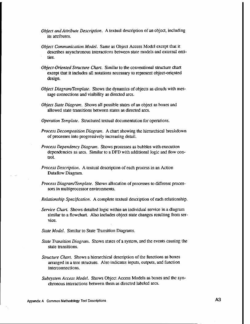
Object and Attribute Description. A textual description of an object, including its attributes.
Object Communication Model. Same as Object Access Model except that it describes asynchronous interactions between state models and external enti- ties.
Object-Oriented Structure Chart. Similar to the conventional structure chart except that it includes all notations necessary to represent object-oriented design.
Object Diagram/Template. Shows the dynamics of objects as clouds with mes- sage connections and visibility as directed arcs.
Object State Diagram. Shows all possible states of an object as boxes and allowed state transitions between states as directed arcs.
Operation Template. Structured textual documentation for operations.
Process Decomposition Diagram. A chart showing the hierarchical breakdown of processes into progressively increasing detail.
Process Dependency Diagram. Shows processes as bubbles with execution dependencies as arcs. Similar to a DFD with additional logic and flow con- trol.
Process Description. A textual description of each process in an Action Dataflow Diagram.
Process Diagram/Template. Shows allocation of processes to different proces- sors in multiprocessor environments.
Relationship Specification. A complete textual description of each relationship.
Service Chart. Shows detailed logic within an individual service in a diagram similar to a flowchart. Also includes object state changes resulting from ser- vice.
State Model. Similar to State Transition Diagrams.
State Transition Diagram. Shows states of a system, and the events causing the state transitions.
Structure Chart. Shows a hierarchical description of the functions as boxes arranged in a tree structure. Also indicates inputs, outputs, and function interconnections.
Subsystem Access Model. Shows Object Access Models as boxes and the syn- chronous interactions between them as directed labeled arcs.
Appendix A Common Methodology Tool Descriptions A3

Subsystem Card. A textual description of a subsystem on a physical card.
Subsystem Communication Model. Shows Object Communication Models as boxes and the asynchronous interactions between them as directed labeled arcs.
Subsystem Relationship Model. Shows information models for each subsystem as boxes and the relationships between them as undirected labeled arcs.
Subsystem Specification. Similar to a class specification but for a subsystem.
System Architecture Diagram. A design level diagram showing the partitioning of the application into subsystems and modules.
Timing Diagram. Shows control flow and event ordering for a group of colla- borating objects.
Venn Diagram. Shows overlapping of responsibilities between classes.
A4 Appendix A Common Methodology Tool Descriptions

Appendix B CASE Vendor Descriptions
The CASE products are listed alphabetically by vendor instead of by name because often there is not just one product represented, but a suite of tools. It is impossible to put each vendor in only one category since the capabilities pro- vided overlap considerably. However, a general category listing is given at the top of each description to separate tool integrators from CASE tools, etc. The product types listed in Appendix B span the following categories:
• Database CASE
• Upper CASE
• Integrated CASE
• Object-oriented CASE
• MetaCASE
• Tool Integrators
The specific software domains and platforms supported are also listed.
Teamwork by CADRE
Category: ICASE Address: 222 Richmond Street, Providence, RI 02903,401-351-5950 Price: Varies significantly Platforms: Most Languages: Ada,C Applications: All types
Appendix B CASE Vendor Descriptions ° '

Cadre provides an integrated suite of tools to support language independent development (upper CASE), and the language dependent environments for Ada and C. Systems analysis tools include modules which can be purchased separately for:
• Static Systems Analysis - DFDs, process specifications, and data dictionary management.
• Real-time Extensions - for modeling control, sequencing, and timing.
• Information Modeling - for modeling of entities, relationships, and attributes for database applications.
• Object-oriented Analysis - support for the Shlaer/Mellor methodology.
• Architecture Design and Assessment - for system level simulation of hardware and software.
• Dynamic Modeling - for simulation of structured analysis and real-time models to understand behavioral characteristics and performance.
• Rapid Application Prototyping - for use with prototype user interfaces to demonstrate the software operation from the specifications.
Cadre has a set of tools to support software design:
• Structured Design - based on standard structured design techniques using structure charts, module specifications, and data dictionary entries.
• Ada Design - direct support for the Ada development environment using Ada structure graphs for Buhr's graphical notation.
• Object-oriented Design - support for the Shlaer/Mellor methodology.
Additional tools are available for C development including reverse engineer- ing, test case generation, and test verification tools. Additional tools for Ada development include a language sensitive editor for adding Ada code to the structure graphs, code generation, and test case generation tools. Other special- ized tools include tools for: reverse engineering of FORTRAN applications, pro- ject management, document generation (including DOD-STD-2167A), and an integration of Teamwork with tools from other vendors.
A 10-seat license is available from Cadre for educational use for the $1,000 annual maintenance fee (with some other requirements).
B2 Appendix B CASE Vendor Descriptions
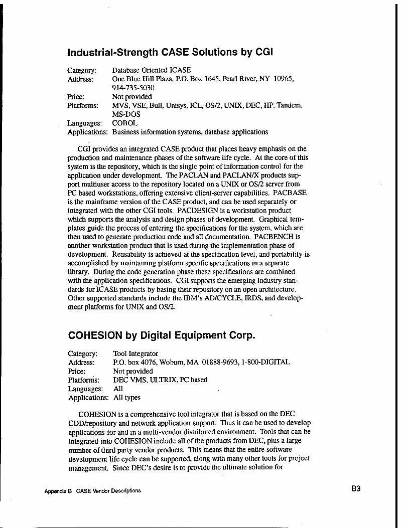
Industrial-Strength CASE Solutions by CGI
Category: Database Oriented ICASE Address: One Blue Hill Plaza, P.O. Box 1645, Pearl River, NY 10965,
914-735-5030 Price: Not provided Platforms: MVS, VSE, Bull, Unisys, ICL, OS/2, UNIX, DEC, HP, Tandem,
MS-DOS Languages: COBOL Applications: Business information systems, database applications
CGI provides an integrated CASE product that places heavy emphasis on the production and maintenance phases of the software life cycle. At the core of this system is the repository, which is the single point of information control for the application under development. The PACLAN and PACLAN/X products sup- port multiuser access to the repository located on a UNK or OS/2 server from PC based workstations, offering extensive client-server capabilities. PACBASE is the mainframe version of the CASE product, and can be used separately or integrated with the other CGI tools. PACDESIGN is a workstation product which supports the analysis and design phases of development. Graphical tem- plates guide the process of entering the specifications for the system, which are then used to generate production code and all documentation. PACBENCH is another workstation product that is used during the implementation phase of development. Reusability is achieved at the specification level, and portability is accomplished by maintaining platform specific specifications in a separate library. During the code generation phase these specifications are combined with the application specifications. CGI supports the emerging industry stan- dards for ICASE products by basing their repository on an open architecture. Other supported standards include the IBM's AD/CYCLE, IRDS, and develop- ment platforms for UNIX and OS/2.
COHESION by Digital Equipment Corp.
Category: Tool Integrator Address: P.O. box 4076, Woburn, MA 01888-9693,1-800-DIGITAL Price: Not provided Platforms: DEC VMS, ULTRIX, PC based Languages: All Applications: All types
COHESION is a comprehensive tool integrator that is based on the DEC CDD/repository and network application support. Thus it can be used to develop applications for and in a multi-vendor distributed environment. Tools that can be integrated into COHESION include all of the products from DEC, plus a large number of third party vendor products. This means that the entire software development life cycle can be supported, along with many other tools for project management. Since DEC'S desire is to provide the ultimate solution for
Appendix B CASE Vendor Descriptions B3

everybody, they are using open standards and architectures to allow other ven- dors to make their tools compatible.
Ada Software Engineering Products by EVB
Category: Ada Applications Address: 5303 Spectrum Drive, Frederick, MD 21701,1-800-877-1815 Price: Not provided Platforms: DOS, Windows, OS/2, SUN, HP, IBM RS6000 Languages: Ada Applications: Any Ada applications, specialize in high-performance interactive
graphical applications
EVB provides several specialized graphical tools for the development of high-performance interactive graphics applications. A database contains an extensive set of two and three dimensional graphical objects and hypertext based online help. An Ada user interface toolkit can be used to design user interfaces and generate the Ada code for these. A reuse library tool set is available for maintaining large repositories of reusable software. These tools are used in con- junction with a special version of the object-oriented CASE tool called Paradigm Plus, from Protosoft. This version supports EVB's own Ada object-oriented development method which can be customized.
OMTool by General Electric
Category: Object-Oriented CASE Address: General Electric Advanced Concepts Center, 640 Freedom Busi
ness Center, P.O. Box 1561, King of Prussia, PA 19406, 800-438-7246
Price: $2,500 per seat Platforms: Sun UNIX Workstation Languages: C++ Applications: All types
OMTool implements General Electric's Object Modeling Technique (OMT), developed by Rumbaugh et al. The tool supports OO analysis, design, database design, and code generation in C++. An extensive GUI enables developers to create 00 diagrams representing classes, attributes, and methods. Convenient drag and drop features along with pop-up forms make entering information intui- tive. Diagrams can be exported in PostScript, or in formats suitable for Interleaf and FrameMaker.
B4 Appendix B CASE Vendor Descriptions

001 by Hamilton Technologies
Category: ICASE Address: 17 Inman Street, Cambridge, MA 02139,617-492-0058 Price: Not Provided Platforms: HP, UNIX, DEC VMS (advertised can be used with anyplatform) Languages: C, Ada Applications: All types
Although Hamilton Technologies has its origins in the defense industry, applications from any software domain can be developed with this integrated CASE tool. 001 is based on the Development Before the Fact™ paradigm which emphasizes error detection and module reuse. Although the product is object- oriented, it does not support any specific standard methodologies. Instead 001 uses FMaps (functional maps) and TMaps (transition maps) to completely specify and design a system. From these, code for any hardware platform can be generated. The 001 AXES™ specification language is able to capture data flows, timing, priority, ordering, and parallelism which may be inherent in the system. The Analyzer™ tool uses mathematically based rules to help eliminate errors that are not normally found until the testing stage. The Resource Allocation Tool™ comes with the C and Ada languages, but has an open architecture that can be programmed to add new language primitives for COBOL, Fortran, graph- ics, or any other language desired. If code generation is not desired, then the system can be executed directly with the Xecutor™. Other tools to support debugging and team management include an object map editor and requirements traceability metrics. Documentation for DOD-STD-2167 can also be generated.
SoftBench by Hewlett-Packard
Category: Tool Integrator Address: 3404 East Harmony Road, Fort Collins, CO 80525,800-637-7740 Price: Not provided Platforms: UNIX, HP-UX, Sun Solaris Languages: C, C++, FORTRAN, Pascal Applications: All types
SoftBench provides extensive capabilities to integrate over 70 tools from 40 different vendors and offer a common user interface. The Encapsulator integrates third party tools into a flexible environment where they communicate transparently. The Message Connector is used to customize how the tools interact and can automate complicated steps that would otherwise have to be performed manually among several different tools. SoftBench has a complete set of tools to support software code development. These include: a version control interface, static analyzer, code browser, code editor, program builder, file com- pare and combine tool, and integrated debugger. Sophisticated graphics enhance the capabilities of all tools, and SoftBench can optionally support UIM/X, HP's GUI interface builder. HPP offers other tightly integrated tools that can be
Appendix B CASE Vendor Descriptions B5

purchased to use with SoftBench such as SynerVision, a process management environment, and ChangeVision, a change request management environment. SoftBench supports distributed environment development and database SQL.
PowerTools by Iconix
Category: Upper CASE Address: Iconix Software Engineering, Inc., 2800 Twenty Eighth Street,
Suite 320, Santa Monica, CA 90406,310-458-0092 Price: $1,000-$7,500, average $5,000 Platforms: Microsoft Windows, OSF/Motif, X Windows, Macintosh Languages: C++, Ada Applications: All types
Iconix PowerTools provide separate modules which can be combined with a multi-user repository to create any type of development environment. The modules may be purchased separately, or combined in lower priced packages to support a particular target application environment. The modules can be com- bined to support all popular types of structure and object-oriented methodolo- gies, including Buhr's methodology for Ada development. A CoCoMo module is available for software project cost estimation. This tool suite supports the entire upper CASE environment but does not generate code.
A PC based demo disk was provided with the documentation for this product.
Software through Pictures by IDE
Category: ICASE Address: 595 Market Street, 10th Floor, San Francisco, CA 94105,1-800-
888-IDE1 Price: Not provided Platforms: UNIX, DEC VMS, HP, Sun Languages: C, Ada Applications: All types
IDE was founded by its current president, A.I. Wasserman, who has made numerous contributions to the development of software engineering techniques. IDE supports an integrated CASE solution by providing a large selection of language independent and language dependent tools which can be mixed and matched with other vendor's tools. The Software Through Pictures family of products is based on the Visible Connections™ open architecture. The products can be used for object-oriented and/or structured design approaches, and have graphical editors that support all of the most popular techniques (including real- time techniques). The shared repository is based on a relational database management system, with a published, extensible schema. The tools can also be integrated with configuration management products native to the particular
gg Appendix B CASE Vendor Descriptions

operating system, such as the CMS for DEC, and SCCS for UNIX. The IDE pro- ducts can be integrated with other integration frameworks such as: HP Soft- Bench, DEC Cohesion, IBM AIX SDE Workbench/6000, and SunSoft ToolTalk. Other features include browsers, knowledge based design and language specific support, DOD-STD-2167A documentation generation, code generation, and reengineering tools.
STATEMATE by l-Logix
Category: Special Purpose ICASE Address: 22 Third Avenue, Burlington, MA 01803,617-272-8090 Price: Not Provided Platforms: DEC VMS, SUNOS, HP UX, Apollo/HP Domain/OS, IBM ADC Languages: C, Ada, Verilog, VHDL Applications: Complex reactive systems such as real-time embedded systems
This tool allows an analyst to build a comprehensive system model that cov- ers the behavioral aspects of the system as well as the usual functional and data flow aspects. This specification model can then be tested and debugged with Statemate analysis tools. Information can be retrieved with Statemate retrieval tools. Activity charts (DFDs), state transition charts, and module charts are simi- lar to their conventional counterparts, but have extra features to capture the behavioral information of a dynamic system. Statemate can be used in conjunc- tion with most structured analysis or object-oriented approaches. There are nota- tional differences, but mapping the related features is straightforward. Basic syntax checking is provided, and simulations of different scenarios at the specification level are supported. The information gathered can be used for debugging, or making further decisions before the design stage. A hierarchical breakdown of high level specifications to low level design can be accomplished with Statemate, and prototyping with a mock-up of the intended user interface can be done. A code generator is available that can produce C or Ada code. A documenter is available for automatically producing DOD-STD-2167A system documentation.
CASE Products by KnowledgeWare, Inc.
Category:. ICASE Address: 3340 Peachtree Road N.E., Atlanta, GA 30326,404-231-8575 Price: $10,750 - $26,500 for various products Platforms: Target: MVS, AS/400, Development: MS-DOS, PC-DOS, OS/2 Languages: Cobol, C/C++, 4GL Applications: Business
The primary products include the Information Engineering Workbench (IEW) for development on MS-/PC-DOS based operating systems, and the Application Development Workbench for OS/2 systems. The integrated products store all
Appendix B CASE Vendor Descriptions B7

information in the proprietary encyclopedia and support most of the software development methodologies including Martin Information Engineering, Yourdon/DeMarco, Gane/Sarson, IDEF, and several others. Optional products provide interfaces to numerous third party CASE tools and publishing applica- tions.
Individual components include the Planning Workstation for high level pro- ject planning and object identification, the Analysis Workstation for developing system specifications, the Design Workstation for low level design from the specifications, and the Construction Workstation for Cobol code generation. The Rapid Development Workstation is used for incorporating end user requirements and operational prototyping. The Documentation Workstation assists with crea- tion of the application documentation derived from information in the encyclo- pedia. All components make extensive use of graphical aids to assist in the development process.
KnowledgeWare is marketing a new product called ObjectView that supports rapid development of client server applications. This Microsoft Windows based tool uses SQL queries to access commercial databases in a distributed environ- ment. Applications can be developed using visual programming, an extended form of BASIC, or C/C++ programming languages. Extensive graphical support is also provided.
ERwin/ERX and BPwin by Logic Works
Category: Database oriented ICASE Address: 214 Carnegie Center, Princeton, NJ 08540,609-243-0088 Price: Not available Platforms: Microsoft Windows, UNIX Languages: SQL Applications: All types
ERwin/ERX is a design tool used for both forward and reverse engineering of client/server database applications. It is used to produce entity-relationship (ER) models of the business rules governing data manipulation in an organization. A point-and-click GUI is used during this phase of development. After the user is satisfied with the ER diagrams, ERwin will automatically generate SQL data definition language statements for tables, indexes, triggers, defaults, and domain constraints. Reports may be produced via interfaces with Microsoft Word, Excel, and Wordperfect.
BPwin provides automated modeling support for business process reengineer- ing. It supports activity modeling using the IDEF0 modeling notation and activity based costing. Helpful display features include automatic ICOM arrow layout, automatic model numbering, user-selectable fonts, and a model zoom capability.
gg Appendix B CASE Vendor Descriptions

ObjectMaker by Mark V Systems
Category: ICASE Address: 16400 Ventura Blvd., Suite 303, Encino, CA 91436,
818-995-7671 Price: $3,000 - $25,000 Platforms: HP/Apollo, Sun, Motorola, DEC, MIPS, Microsoft Windows,
Microsoft Windows NT, Macintosh Languages: C, C++, Ada Applications: All types
ObjectMaker is an object-oriented integrated CASE tool which can support all phases of the software development life cycle. The product provides support for over 20 of the most common object-oriented, behavior-oriented, and struc- tured methods. With separate language modules code can be generated as well as reverse engineered. A shared repository links all methods. Diagram export to several popular word processors and technical publishing products is supported. The unique feature about this product is that it is customizable through the use of an extension language based on rules. This allows the tool to be tailored to specific project needs and may incorporate software metrics.
PRIDE Information Factory by M. Bryce & Associates
Category: Tool Integrator Address: 777 Alderman Road, Palm Harbor, FL 34683, 813-786-4567 Price: $15,000 -$25,000 Platforms: OS/2 Languages: Any Applications: Any
This is a tool integrator based on the information factory concept of software development. This concept includes more than just computer software; it includes the management of all types of information resources. These are the business, system, and data resources within an organization. The PRIDE product uses an information manager which contains a repository based system that binds all tools and information together in a proprietary database. The architec- ture consists of three methodologies:
• Enterprise Engineering Methodology - for defining business resources and strategy.
• Information Systems Engineering Methodology - for building total informa- tion systems, not just the software portions.
• Database Engineering Methodology - for designing the corporate database.
Appendix B CASE Vendor Descriptions "9

The production management system provides planning, estimating, schedul- ing, reporting, and control, all at the project level. Graphics facilities support all types of project planning diagrams and charts including: hierarchy, flowchart, scheduling, structure, and matrix.
ObjectCraft by Object Oriented Technologies
Category: Low Cost PC based Visual Programming Tool Address: 2124 Kittredge Street, Suite 118, Berkeley, CA 94704,
415-759-6270 Price: $200 - $400 Platforms: DOS, Windows (1 st quarter 1994) Languages: C++, Turbo Pascal Applications: General Purpose Programming
ObjectCraft is a low-cost graphical programming tool for object-oriented applications. The applications are created visually using ovals to represent objects and classes with lines between to show relationships. All of the object- oriented properties are supported. The applications can be run iteratively within the tool, or code can be generated for compilation (compiler not included). ObjectCraft was developed by Paul Harmon, the creator of AI Expert, which is a popular low-cost expert system shell.
Database Management Tools by ONTOS
Category: Database Oriented Address: Three Burlington Woods, Burlington, MA 01803,617-272-7110 Price: $5000 Platforms: IBM, DEC, Sun, HP Languages: C++ Applications: Database
ONTOS is an object-oriented database management system. It can be used in a distributed client-server environment, and offers several tools for C++ pro- gramming development. The product is based on IBM's System Object Model technology which allows interoperability between application written in different object-oriented languages. Since applications are based on a consistent object-oriented model, applications written in one language can invoke object methods written in another language. The available tools include a C++ applica- tion programmer interface, a graphical database design tool and browser, an interactive front-end development tool, an object-oriented data manipulation language, and a structured query language. The ONTOS database system can be used with a product called ObjectCenter from Centerline Software, which is a database software development environment.
g4Q Appendix B CASE Vendor Descriptions

System Architect by Popkin Software & Systems, Inc.
Category: Upper CASE, Database Oriented ICASE Address: 11 Park Place, New York, NY 10007-2801,212-571-3434 Price: $895 - $ 1,995 per seat Platforms: Microsoft Windows, OS/2 Languages: 4GL and SQL (optional) Applications: All types
Like more expensive CASE tools System Architect provides an integrated environment for software development. Multiple structured analysis and design methodologies are supported including DeMarco/Yourdon, Ward & Mellor real- time, and Gane/Sarson. If the Object-Oriented Analysis and Design Module is purchased, then Booch91, Coad/Yourdon, and Shlaer/Mellor methodologies are also supported. Structure charts, entity-relationship diagrams, flow charts, and decomposition diagrams are available. Automated reporting and documentation facilities, along with tracking capabilities at each stage of the software life cycle, provide the necessary project management functions. The proprietary data dic- tionary supports concurrent developer access in the network version of the pro- duct. A spreadsheet interface is provided, as well as the general ascii import/export interface. Multiple windows, GUI support, and online help is pro- vided.
Two optional products extend the capabilities of the base product. The first is the Schema Generator, which is used to generate 4GL code and SQL queries in support of 14 commercial database environments. The Screen Painter is avail- able for creating both GUI and character based screens.
Paradigm Plus by Protosoft
Category: MetaCASE, ICASE Address: 17629 El Camino Real, Suite 202, Houston, TX 77058,
713-480-3233 Price: Not available Platforms: DOS/Windows, OS/2, SunOS, HP9000, IBM RS6000 Languages: C, C++, Ada, Smalltalk Applications: All types
Paradigm Plus is described as an object-oriented MetaCASE tool and pro- vides support for the entire software development life cycle. Multiple users can access its object based repository. Full automation for the Rumbaugh, Booch, HP Fusion, and other object-oriented methodologies is provided. It is configurable and has a script language available for customization of reports, checking, and code generation. Additional modeling is provided for project management tasks and multi-processor allocation. Powerful graphics capabili- ties are augmented by capture, view, and browsing tools along with hypertext
Appendix B CASE Vendor Descriptions B11

online help. Standard analysis and design reports can be automatically gen- erated. Security restrictions can be implemented if desired. The product may be distributed across a network and can develop applications based on the client- server model. The Paradigm Plus open architecture allows it to be integrated with other vendor's tools.
A PC compatible demonstration disk was shipped with the overview docu- mentation for this product.
CASE Products by Rational
Category: Ada Programming and CASE Address: 3320 Scott Boulevard, Santa Clara, CA 95054-3197,
408-496-3600 Price: Not provided Platforms: Sun SPARC, IBM RS/6000 Languages: Ada Applications: All types
The next generation of Rational products provides the same tightly integrated compatibility between tools, but is not tied to dedicated hardware. The open sys- tems family of products covers the entire software life cycle. The main product, Rational Apex, is the successor to the original Rational Environment, a powerful Ada programming development environment. Rational Apex, like its predeces- sor, is based on a persistent intermediate representation, which allows developers to manage information about the software, as well as the software, in an object based repository. This representation is based on DIANA, an industry standard for Ada program development. In addition to managing code, the Apex environ- ment also manages other programming details including requirements and design. Another feature, optimal recompilation, is the next step up from the Rational Environment's incremental recompilation model. With optimal recom- pilation, only individual lines that depend on the changes made will be recom- piled, rather than entire modules, and is invoked automatically. The Rational Apex package includes the configuration management and version control (CMVC) to manage the complexity of a multi-user environment and multiple versions of software. The subsystem architecture complexity can be easily managed with Rational's Subsystems component of the Apex package. If the Ada code is to be used on an RS/6000 or Sun SPARC system, then Rational's Compilation Integrator can be used to generate the code. However, the environ- ment is also designed to work with all Ada compilers and target processors. Another product called Testmate is available to automate the testing process and evaluate results.
The Rational Insight product provides reverse engineering capability for Ada applications and is based on the Booch methodology. Additional browsing capa- bility augments the tool to better understand and reengineer software.
Q-J2 Appendix B CASE Vendor Descriptions
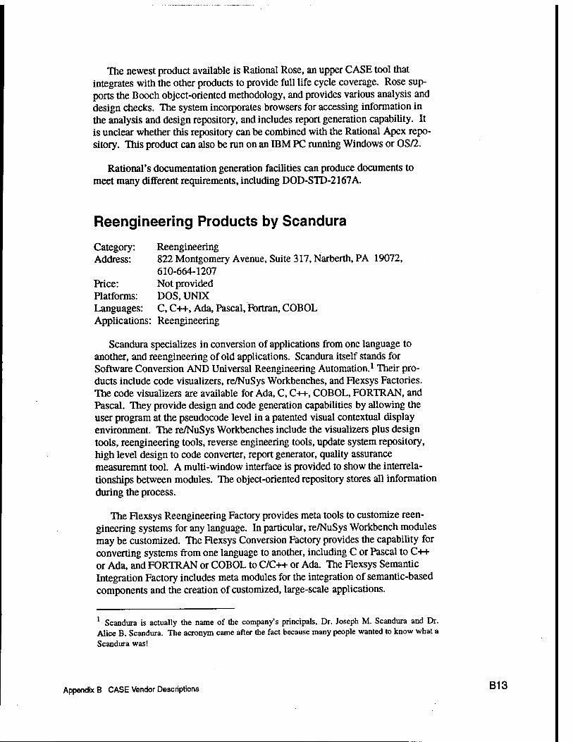
The newest product available is Rational Rose, an upper CASE tool that integrates with the other products to provide full life cycle coverage. Rose sup- ports the Booch object-oriented methodology, and provides various analysis and design checks. The system incorporates browsers for accessing information in the analysis and design repository, and includes report generation capability. It is unclear whether this repository can be combined with the Rational Apex repo- sitory. This product can also be run on an IBM PC running Windows or OS/2.
Rational's documentation generation facilities can produce documents to meet many different requirements, including DOD-STD-2167A.
Reengineering Products by Scandura
Category: Reengineering Address: 822 Montgomery Avenue, Suite 317, Narberth, PA 19072,
610-664-1207 Price: Not provided Platforms: DOS, UNIX Languages: C, C++, Ada, Pascal, Fortran, COBOL Applications: Reengineering
Scandura specializes in conversion of applications from one language to another, and reengineering of old applications. Scandura itself stands for Software Conversion AND Universal Reengineering Automation.1 Their pro- ducts include code visualizers, re/NuSys Workbenches, and Flexsys Factories. The code visualizers are available for Ada, C, C++, COBOL, FORTRAN, and Pascal. They provide design and code generation capabilities by allowing the user program at the pseudocode level in a patented visual contextual display environment. The re/NuSys Workbenches include the visualizers plus design tools, reengineering tools, reverse engineering tools, update system repository, high level design to code converter, report generator, quality assurance measuremnt tool. A multi-window interface is provided to show the interrela- tionships between modules. The object-oriented repository stores all information during the process.
The Flexsys Reengineering Factory provides meta tools to customize reen- gineering systems for any language. In particular, re/NuSys Workbench modules may be customized. The Flexsys Conversion Factory provides the capability for converting systems from one language to another, including C or Pascal to C++ or Ada, and FORTRAN or COBOL to C/C++ or Ada. The Flexsys Semantic Integration Factory includes meta modules for the integration of semantic-based components and the creation of customized, large-scale applications.
1 Scandura is actually the name of the company's principals. Dr. Joseph M. Scandura and Dr. Alice B. Scandura. The acronym came after the fact because many people wanted to know what a Scandura was!
Appendix B CASE Vendor Descriptions B13

Exchange by Software One
Category: Tool Integrator Address: Mere Park, Marlow, Bucks SL7 1FJ, +44-628-891891 Price: Not provided Platforms: Microsoft Windows Languages: Not applicable Applications: Not applicable
Exchange is a tool integrator for the IBM PC environment. Instead of using a collection of binary bridges between tools, Exchange provides a universal inter- face based on a generic metamodel. Encode/decode rules are used to transfer information from a supported vendor's tools into the Exchange database and is represented as a generic model. Exchange then performs consistency and valida- tion checks. The information can then be recoded and transferred to any other target tool or platform. Exchange uses its own control database to support this process.
Software Development Products by Software Systems Design
Category: ICASE Address: 3627 Padua Avenue, Claremont, CA 91711,714-625-6147 Price: $2,000 - $9,000 Platforms: SUN, DEC, HP, Apollo, UNIX Languages: C, Ada Applications: All types
Software Systems Design provides an integrated suite of tools for C or Ada. Basically this includes tools for: analysis, design, code generation, testing, and document generatioa An interface system allows all the tools to work together with a data dictionary. This product makes extensive use of knowledge based expert technology to assist the software engineer throughout the entire process. The modules and code generated is object-oriented, and DOD-STD-2167A docu- mentation standards are supported.
A demonstration version is available for $150.
G++ by SYCO
Category: Special Purpose ICASE Address: V. Morghen n. 4,10143 Turin ITALY, 39-11-74 8347 Price: Not provided Platforms: UNIX, soon on OS/2 and Windows Languages: C++
g-j 4 Appendix B CASE Vendor Descriptions

Applications: Computer Integrated Manufacturing (CIM) systems
G++ is specifically designed for object-oriented modeling and software development of concurrent distributed applications in the CIM environment. It is based on a framework of reusable classes and an evolutionary development process supporting the spiral life cycle model. This integrated CASE tool suite includes graphical tools for analysis, design, prototyping, and code generation. Analysis and high level design is accomplished using entity relationship diagrams with a specialized graphical editor. Class design is accomplished using the ESA-HOOD modeling technique, which uses the high level design information and can produce source code. The object-oriented extension of the specification and design language (SDL) standardized by the CCITT is used to specify concurrent dynamic behavior characteristics. It can also be used as a prototyping tool.
Information Engineering Facility by Texas Instruments
Category: Database Oriented ICASE Address: 13532 N. Central Expressway, P.O. Box 655012, Dallas, TX
75265,214-995-6611 Price: Not provided Platforms: IBM MVS, DEC VMS, HP, Tandem, Microsoft Windows, OS/2 Languages: C, COBOL Applications: Business information systems, database applications
IEF is an integrated CASE product that includes tool sets for the highest level business planning needs to the lowest level implementation needs. It has an extensive encyclopedia (repository) containing all of the high level, analysis, and design information. This main repository resides on an IBM MVS host computer with network access through design workstations. Code can be generated for any of the listed platforms (above). Database applications using commercial databases are the primary use of this product. The standard structured and infor- mation modeling methodologies are supported. An added facility for executing and testing the target application is provided, and interactive testing at the diagram level can also be performed. IEF documentation advertises that 100% of the application can be generated using the tools provided (no patching).
CASE Products by Verilog
Category: ICASE Address: Verilog, Inc., 3010 LBJ Freeway, Suite 900, Dallas, TX 75234,
214-241-6595 Price: Not provided Platforms: UNDC, VMS
Appendix B CASE Vendor Descriptions B15
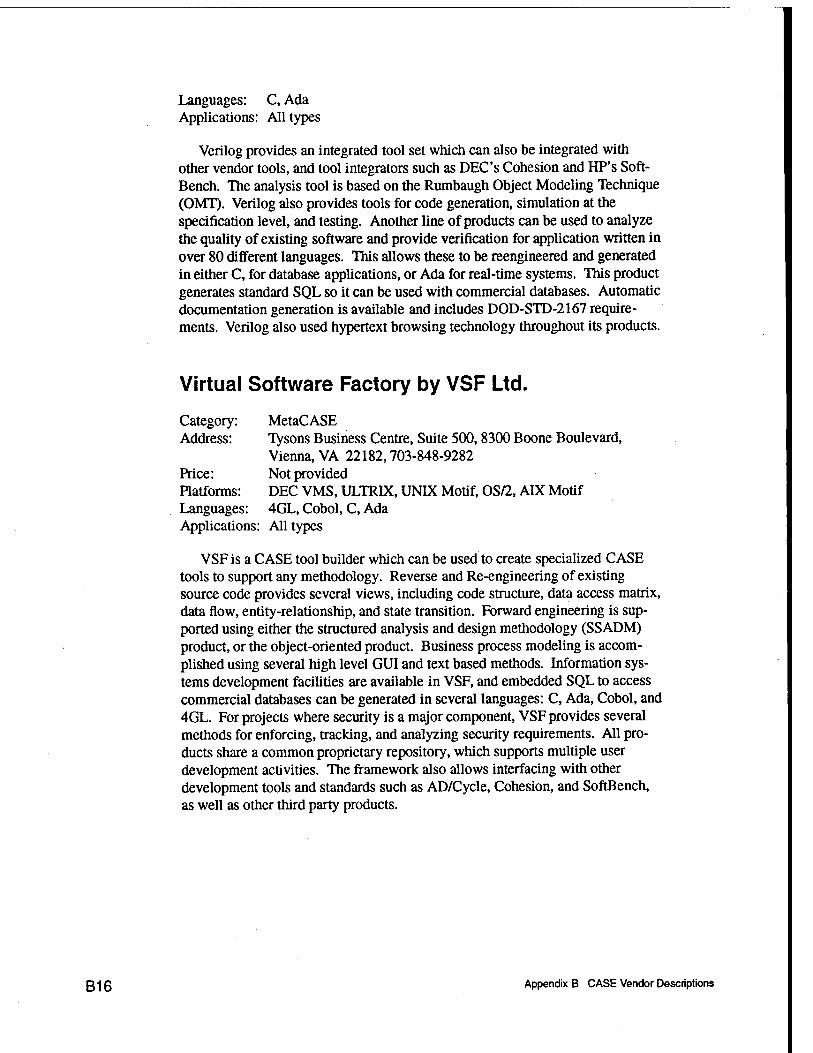
Languages: C, Ada Applications: All types
Verilog provides an integrated tool set which can also be integrated with other vendor tools, and tool integrators such as DEC'S Cohesion and HP's Soft- Bench. The analysis tool is based on the Rumbaugh Object Modeling Technique (OMT). Verilog also provides tools for code generation, simulation at the specification level, and testing. Another line of products can be used to analyze the quality of existing software and provide verification for application written in over 80 different languages. This allows these to be reengineered and generated in either C, for database applications, or Ada for real-time systems. This product generates standard SQL so it can be used with commercial databases. Automatic documentation generation is available and includes DOD-STD-2167 require- ments. Verilog also used hypertext browsing technology throughout its products.
Virtual Software Factory by VSF Ltd.
Category: MetaCASE Address: Tysons Business Centre, Suite 500,8300 Boone Boulevard,
Vienna, VA 22182,703-848-9282 Price: Not provided Platforms: DEC VMS, ULTRIX, UNFX Motif, OS/2, ADC Motif Languages: 4GL, Cobol, C, Ada Applications: All types
VSF is a CASE tool builder which can be used to create specialized CASE tools to support any methodology. Reverse and Re-engineering of existing source code provides several views, including code structure, data access matrix, data flow, entity-relationship, and state transition. Forward engineering is sup- ported using either the structured analysis and design methodology (SSADM) product, or the object-oriented product. Business process modeling is accom- plished using several high level GUI and text based methods. Information sys- tems development facilities are available in VSF, and embedded SQL to access commercial databases can be generated in several languages: C, Ada, Cobol, and 4GL. For projects where security is a major component, VSF provides several methods for enforcing, tracking, and analyzing security requirements. All pro- ducts share a common proprietary repository, which supports multiple user development activities. The framework also allows interfacing with other development tools and standards such as AD/Cycle, Cohesion, and SoftBench, as well as other third party products.
g-j g Appendix B CASE Vendor Descriptions

Visible Analyst Workbench by Visible Systems Corp.
Category: Database Oriented Address: 950 Winter Street, Waltham, MA 02154,617-890-CASE Price: Not provided Platforms: DOS/Windows, many others not specifically mentioned Languages: C, COBOL Applications: General purpose and business information systems
VAW provides an integrated full life cycle CASE solution. It supports all of the popular structured methodologies for: functional decomposition modeling, entity relationship modeling, data flow modeling, and structure chart modeling. C, COBOL, and various SQL schema can be generated. A comprehensive repo- sitory is automatically populated from the graphical interfaces. Syntax and com- pleteness checks are performed, and design complexity can be measured. VAW supports SQL reverse engineering and client-server technology. Integration with a number of other vendor's products is also possible.
A scaled down student software version of this product for the IBM PC is available for about $250. Special pricing on university editions is also available.
ICASE Tools by Westmount
Category: Database Oriented ICASE Address: 1555 Wilson Blvd., Suite 300, Arlington, VA 22209,
703-875-8799 Price: Not provided Platforms: Apollo, Data General, DEC, HP, IBM RS 600, Sun Languages: Westmount 4GL, SQL Applications: Database, Business information systems
Westmount supplies tools for application development in a database environ- ment. The tools support the structured analysis and design techniques of Your- don and include DFDs, E-R diagrams, data structure design diagrams, structure charts, and state transition diagrams. The system generates 4GL code with stan- dard SQL, which can be used with most commercial databases. The program- ming environment also provides testing support. A document writing workbench integrated with the FrameMaker desktop publishing package can be used to develop system documentation with graphics. A project management tool is under development.
Appendix B CASE Vendor Descriptions B17

CASE Products by York Software Engineering
Category: Upper CASE, Ada Development Address: University of York, York YOl 5DD, England, +44 (0)904 433741 Price: Not provided Platforms: MS-DOS Languages: Ada Applications: All types
York Software Engineering provides several tools to aid in the development of software. The PC based SELECT product is an upper CASE tool which sup- ports the analysis and design phases of the software life cycle. The Yourdon methodology with Ward-Mellor and Hatley extensions is supported, as well as the HOOD and SSADM methodologies. A central repository captures all design information and supports multiple concurrent users (with most popular network configurations). Smaller projects with their own repositories can be merged into one large project Other DOS programs can be integrated with SELECT.
For Ada program development on a UNIX system, York offers the Ada Com- piler Environment (ACE), with accompanying debugger, library management tools, and other utilities.
If the requirements for a project are to be specified formally using the language Z, York offers their Computer Aided Design in Z (CADiZ) tool. This UNDC based product helps manage, preview, and check the requirements specified in Z.
DesignAid II by Yourdon
Category: PC based Upper CASE Address: 8521 Six Forks Road, Suite 400, Raleigh, NC 27615,
919-847-9508 Price: Not provided. Platforms: IBM PC Languages: Not applicable Applications: All types
DesignAid II is an upper CASE PC based tool with an interactive multi-user repository. The analysis techniques supported include: data-information model- ing, Yourdon/DeMarco process modeling, and Ward/Mellor and Hatley real-time modeling. Automatic data normalization can be performed to the third normal form. Diagrams can be automatically generated from textual input. Rule based analysis and balancing is used to validate models created in Design Aid II. An SQL like language can be used to access the repository. Reverse engineering tools are available for COBOL.
o-tQ Appendix B CASE Vendor Descriptions
Appendix C Software Technology Support Center Reports
Project Management Tools Report, March 1992 Requirements Analysis & Design Tools Report, April 1992 Software Documentation Tool Report, March 1993 Software Engineering Environment Report, March 1992 Software Estimation Technology Report, March 1993 Software Management Guide, Third Printing, April 1992 Source Code Static Analysis Technologies Report (Volumes I & II),
March 1993 Test Preparation, Execution, & Evaluation Software Technologies
Report, February 1993
These reports are available from:
Software Technology Support Center (STSC) Attn: Customer Service OO-ALC/TISE Hill AFB, Utah 84056 Phone: 801-777-7703 Fax: 801-777-8069
C1 Appendix C Software Technology Support Center Reports
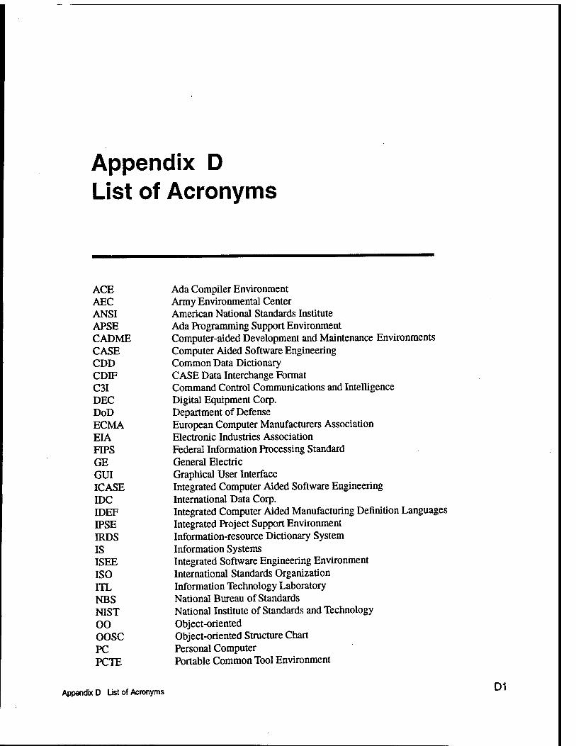
Appendix D List of Acronyms
ACE Ada Compiler Environment AEC Army Environmental Center ANSI American National Standards Institute APSE Ada Programming Support Environment CADME Computer-aided Development and Maintenance Environments CASE Computer Aided Software Engineering CDD Common Data Dictionary CDIF CASE Data Interchange Format C3I Command Control Communications and Intelligence DEC Digital Equipment Corp. DoD Department of Defense ECMA European Computer Manufacturers Association EIA Electronic Industries Association FIPS Federal Information Processing Standard GE General Electric GUI Graphical User Interface ICASE Integrated Computer Aided Software Engineering IDC International Data Corp. IDEF Integrated Computer Aided Manufacturing Definition Languages IPSE Integrated Project Support Environment IRDS Information-resource Dictionary System IS Information Systems ISEE Integrated Software Engineering Environment ISO International Standards Organization ITL Information Technology Laboratory NBS National Bureau of Standards NIST National Institute of Standards and Technology 00 Object-oriented OOSC Object-oriented Structure Chart PC Personal Computer PCTE Portable Common Tool Environment
Appendix D List of Acronyms D1

RAD Rapid Application Development RM/MVS Repository Manager/MVS SDE Software Development Environment SDL Specification and Description Language standardized by CCIT SDM Software Design Methodology SEE Software Engineering Environment SEI Software Engineering Institute at Carnegie Mellon SREM Software Requirements Engineering Methodology SSADM Structured Systems Analysis and Design Methodology STEC Software Tools Evaluation Committee at Westinghouse Corp. STS Software Technology Service STSC Software Technology Support Service WES Waterways Experiment Station
D2 Appendix D List of Acronyms

REPORT DOCUMENTATION PAGE Form Approved
OMBNo. 074-0188
Public „porting burd.n for Ihl. coH.ctlon of Inform.tlon I. ..tlm.t.d lo .«...,. 1 hou, p.c ...pon... Inctudlnfl th. Um. lo, r.vl.wln, l™*™*™-™^**'^"^™™ o.Th.rlno.no m.int.lning th. d.t. n..d.d. .nd competing .nd r.vl.wlng Ih. eoll.cllon of Inform.tlon. S.nd comm.nt. r.g.rdlng Ihl. burd.n ..tm.t. or «ny oth.r ..p.ot of Ihl. JA ^»Sl».'^'.«», ........... for r.ducln, thl. burd.n. to W..h,n,,on H..d,u.r,.,. S.rvlc... ™<'«°"»<°<^^^ *-"" eoll.cllon D.vl. Highway, Suit. 1204, Arlington, VA 22202-4302. .nd to th. Olfic. of M.n.g.m.nt «nd Budg.t, P.p.rwork R.duetlon Pro).ct (0704-016«), W«»hln.ton, DC 20508.
1. AGENCY USE ONLY (Leave blank) 2. REPORT DATE September 1995
3. REPORT TYPE AND DATES COVERED Final Report
4. TITLE AND SUBTITLE CASE Environments: A Survey of
Methodologies, Capabilities, and Trends
6. AUTHOR(S)
Rhonda J. Vickery, William A. Ward, Jr.
7. PERFORMING ORGANIZATION NAME(S) AND ADDRESS(ES)
Faculty Court West 20 School of Computer and Information Sciences University of South Alabama Mobile, AL 36688
9. SPONSORING/MONITORING AGENCY NAME(S) AND ADDRESS(ES)
Information Technology Laboratory U.S. Army Engineer Waterways Experiment Station 3909 Halls Ferry Road, Vicksburg, MS 39180-6199
5. FUNDING NUMBERS
8. PERFORMING ORGANIZATION REPORT NUMBER
Technical Report USA/CIS-94-TR-03
10. SPONSORING/MONITORING AGENCY REPORT NUMBER
Technical Report ITL-95-10
11. SUPPLEMENTARY NOTES
12a. DISTRIBUTION/AVAILABILITY STATEMENT
Approved for public release; distribution is unlimited
12b. DISTRIBUTION CODE
13. ABSTRACT (Maximum 200 words)
Software development has evolved to be an organized discipline involving a team of programmers developing large complex systems. The future success of software engineering is inextricably woven with the success of Integrated Computer Aided Software Engineering (ICASE) tools, which automate the entire life cycle process. ICASE tools allow standardized processes to be put in place to reduce costs, and large projects to be main- tained with a high level of quality. This study provides background on the development of ICASE tools and how they enhance the software development process. A presentation of the major considerations behind the use of different ICASE tools is made, along with a cross-section of the ICASE products currently available on
the market
14. SUBJECT TERMS
CASE environments, software engineering, software development tools
17. SECURITY CLASSIFICATION OF REPORT
UNCLASSIFIED
18. SECURITY CLASSIFICATION OF THIS PAGE
UNCLASSIFIED
19. SECURITY CLASSIFICATION OF ABSTRACT
15. NUMBER OF PAGES 97
16. PRICE CODE
20. LIMITATION OF ABSTRACT
NSN 7540-01-280-5500 Standard Form 298 (Rev. 2-89) Prescribed by ANSI Std. 23S-18 298-102