Embed Size (px)
Citation preview

1
2
3
4
5
6
7
8
9
10
11
12
13
14
15
16
17
18
19
20
21
22
23
24
25
26
27
28
WEST\277551502 DEFENDANTS’ MOTION FOR SUMMARY JUDGMENT Case Nos.: 3:12-CV-03865; -03876; -03877; -03880; -03881
(Counsel listed on signature page)
UNITED STATES DISTRICT COURT
NORTHERN DISTRICT OF CALIFORNIA
SAN FRANCISCO DIVISION
TECHNOLOGY PROPERTIES LIMITED LLC, et al., Plaintiffs, v. HUAWEI TECHNOLOGIES CO., LTD., et al., Defendants.
Case No. 3:12-cv-03865-VC DEFENDANTS’ MOTION FOR SUMMARY JUDGMENT DATE: November 30, 2017 TIME: 10:00 AM PLACE: Courtroom 4, 17th floor JUDGE: Hon. Vince Chhabria
TECHNOLOGY PROPERTIES LIMITED LLC, et al.,
Plaintiffs,
v.
ZTE CORPORATION, et al., Defendants.
Case No. 3:12-cv-03876-VC
REDACTED VERSION OF DOCUMENT SOUGHT TO BE SEALED
TECHNOLOGY PROPERTIES LIMITED LLC, et al., Plaintiffs, v. SAMSUNG ELECTRONICS CO., LTD., et al., Defendants.
Case No. 3:12-cv-03877-VC
Case 3:12-cv-03880-VC Document 157 Filed 09/29/17 Page 1 of 47
1
2
3
4
5
6
7
8
9
10
11
12
13
14
15
16
17
18
19
20
21
22
23
24
25
26
27
28
WEST\277551502 DEFENDANTS’ MOTION FOR SUMMARY JUDGMENT Case Nos.: 3:12-CV-03865; -03876; -03877; -03880; -03881
TECHNOLOGY PROPERTIES LIMITED LLC, et al., Plaintiffs, v. LG ELECTRONICS, INC., et al., Defendants.
Case No. 3:12-cv-03880-VC
TECHNOLOGY PROPERTIES LIMITED LLC, et al., Plaintiffs, v. NINTENDO CO., LTD, et al. Defendants.
Case No. 3:12-cv-03881-VC
Case 3:12-cv-03880-VC Document 157 Filed 09/29/17 Page 2 of 47

1
2
3
4
5
6
7
8
9
10
11
12
13
14
15
16
17
18
19
20
21
22
23
24
25
26
27
28
TABLE OF CONTENTS
Page
WEST\277551502 -i- DEFENDANTS’ MOTION FOR SUMMARY JUDGMENT Case Nos.: 3:12-CV-03865; -03876; -03877; -03880; -03881
I. INTRODUCTION .............................................................................................................. 1
II. PROCEDURAL AND FACTUAL BACKGROUND ........................................................ 3
A. Procedural History .................................................................................................. 3
B. Overview Of The ’336 Patent ................................................................................. 5
C. The Accused Products ............................................................................................. 6
III. LEGAL STANDARD FOR SUMMARY JUDGMENT .................................................. 13
IV. SUMMARY JUDGMENT SHOULD BE GRANTED IN THIS CASE .......................... 13
A. Disclaimer Based On Sheets ................................................................................. 14
1. The accused oscillators require a command input to change frequency ................................................................................................... 15
a. The accused oscillators output a fixed frequency ......................... 15
b. Empirical evidence confirms the PLL’s frequency is fixed .......... 16
c. A command input is required to change the output frequency value of the PLL in the accused products .................... 20
2. Each of TPL’s four theoretical infringement theories is meritless ........... 22
a. TPL’s theory regarding frequency variations when the PLL is “locked” lacks merit .................................................................. 23
b. TPL’s infringement theory regarding pre-phase lock frequency variations lacks merit ................................................... 25
c. TPL’s additional infringement theories regarding variation during phase lock lack merit ......................................................... 26
d. TPL’s “thermal throttling” infringement theory lacks merit......... 27
B. Disclaimer Based On Magar ................................................................................. 29
1. The frequency of the accused oscillators is fixed by an external crystal ........................................................................................................ 30
2. TPL’s infringement theories are meritless ................................................ 31
a. TPL’s theory that the accused oscillators are “inherently variable” is incorrect ..................................................................... 31
b. TPL is incorrect that the PLL’s controlled frequency changes satisfy the Court’s claim construction ............................. 32
(1) TPL’s contention regarding intentional frequency changes by the PLL is incorrect ........................................ 32
(2) TPL’s interpretation of “fixed” is incorrect ...................... 34
(a) TPL’s interpretation of “fixed” is inconsistent with the specification ........................ 34
(b) TPL’s interpretation of “fixed” is inconsistent with its statements during prosecution ............................................................ 35
Case 3:12-cv-03880-VC Document 157 Filed 09/29/17 Page 3 of 47

1
2
3
4
5
6
7
8
9
10
11
12
13
14
15
16
17
18
19
20
21
22
23
24
25
26
27
28
TABLE OF CONTENTS (continued)
Page
WEST\277551502 -ii- DEFENDANTS’ MOTION FOR SUMMARY JUDGMENT Case Nos.: 3:12-CV-03865; -03876; -03877; -03880; -03881
(c) TPL’s reading of “fixed” is inconsistent with this Court’s and the Federal Circuit’s rulings ....... 37
V. CONCLUSION ................................................................................................................. 38
Case 3:12-cv-03880-VC Document 157 Filed 09/29/17 Page 4 of 47

1
2
3
4
5
6
7
8
9
10
11
12
13
14
15
16
17
18
19
20
21
22
23
24
25
26
27
28
WEST\277551502 -iii- DEFENDANTS’ MOTION FOR SUMMARY JUDGMENT Case Nos.: 3:12-CV-03865; -03876; -03877; -03880; -03881
TABLE OF AUTHORITIES
Page(s)
Cases
Anderson v. Liberty Lobby, Inc., 477 U.S. 242 (1986) ..................................................................................................................13
Celotex Corp. v. Catrett, 477 U.S. 317 (1986) ..................................................................................................................13
Computer Docking Station Corp. v. Dell, Inc., 519 F.3d 1366 (Fed. Cir. 2008) .................................................................................................37
Southwall Techs., Inc. v. Cardinal IG Co., 54 F.3d 1570 (Fed. Cir. 1995) ...................................................................................................37
Tech. Props. Ltd., et al. v. Samsung Elecs. Co., Ltd. et al., Case No. 12-cv-03877-VC ..........................................................................................................2
Tech. Props. Ltd. LLC v. Huawei Techs. Co., 849 F.3d 1349 (Fed. Cir. 2017) ......................................................................................... passim
Other Authorities
Fed. R. Civ. P. 56(a) ........................................................................................................................13
Case 3:12-cv-03880-VC Document 157 Filed 09/29/17 Page 5 of 47

1
2
3
4
5
6
7
8
9
10
11
12
13
14
15
16
17
18
19
20
21
22
23
24
25
26
27
28
WEST\277551502 -1- DEFENDANTS’ MOTION FOR SUMMARY JUDGMENT Case Nos.: 3:12-CV-03865; -03876; -03877; -03880; -03881
NOTICE OF MOTION
TO ALL PARTIES AND THEIR ATTORNEYS OF RECORD:
PLEASE TAKE NOTICE that on November 30, 2017 at 10:00 a.m., in Courtroom 4 of
this Court, located at 450 Golden Gate Avenue, 17th floor, San Francisco, California, 94102,
Defendants Huawei Technologies Co., Ltd., Huawei Device Co., Ltd., Huawei Device USA, Inc.,
Futurewei Technologies, Inc., Huawei Technologies USA, Inc., ZTE Corporation, ZTE (USA)
Inc., Samsung Electronics Co., Ltd., Samsung Electronics America, Inc., LG Electronics, Inc.,
LG Electronics U.S.A., Inc., Nintendo Co., Ltd., and Nintendo of America Inc. (collectively,
“Defendants”) will move for summary judgment that they do not infringe claims 6, 7, 9, 13, 14
and 15 (the “asserted claims”) of U.S. Patent No. 5,809,336 (the “’336 patent”).
This motion is based on this Notice of Motion, the attached memorandum of points and
authorities in support thereof, the pleadings and documents on file in this case, the declarations of
Erik Fuehrer (“Fuehrer Decl.”), Dr. Vivek Subramanian (“Subramanian Decl.”), Marzio Pedrali-
Noy (“Pedrali-Noy Decl.”), Dr. Jaegon Lee (“Lee Decl.”) and their respective exhibits, and such
other evidence and argument as may be presented at the hearing on this motion.
STATEMENT OF ISSUES TO BE DECIDED
1. Whether Defendants infringe the asserted claims of the ’336 patent.
MEMORANDUM OF POINTS AND AUTHORITIES
I. INTRODUCTION
This case effectively ended with the Federal Circuit’s recent opinion. The Federal Circuit
affirmed this Court’s prior construction with only a “minor modification” that the Federal Circuit
noted “likely does not affect the outcome of this case.” Tech. Props. Ltd. LLC v. Huawei Techs.
Co., 849 F.3d 1349, 1358-60 (Fed. Cir. 2017). The outcome of this case has not changed: the
accused products do not infringe.
Following this Court’s claim construction, Plaintiffs (collectively “TPL”) stipulated that
Case 3:12-cv-03880-VC Document 157 Filed 09/29/17 Page 6 of 47

1
2
3
4
5
6
7
8
9
10
11
12
13
14
15
16
17
18
19
20
21
22
23
24
25
26
27
28
WEST\277551502 -2- DEFENDANTS’ MOTION FOR SUMMARY JUDGMENT Case Nos.: 3:12-CV-03865; -03876; -03877; -03880; -03881
Defendants’ accused products do not infringe any asserted claim of the ’336 patent under this
Court’s prior claim construction. Plaintiffs acknowledged that if a court did not reject or
“materially modify” the Court’s construction this case could not proceed. Dkt. No. 1051 at ¶ 5.
The Federal Circuit did neither. The Federal Circuit’s “minor” modification does not change the
conclusion that the International Trade Commission, as well as Plaintiffs and its prior counsel,
reached years ago -- the accused products do not infringe.
Yet, Plaintiffs now seek to improperly prolong this litigation (through a third-set of new
attorneys). TPL recently served Second Amended Infringement Contentions (“SAIC”) that
contain an array of newly concocted, factually unsupported infringement theories. The SAICs are
a last ditch and meritless attempt to circumvent an adverse judgment. TPL never explains how
the “minor modification” of this Court’s claim construction that “likely does not affect the
outcome of this case” now provides a basis to allege new infringement theories regarding the
exact same product designs it previously conceded do not infringe.
As established below, the accused products are, and have always been, the antithesis of
the claimed invention. The ’336 patent claims a variable speed oscillator whose frequency
automatically varies in real time based upon its environmental conditions (including temperature
and voltage) without any command input. In contrast, the accused products specifically are
designed and operate to avoid such variations by using an oscillator (1) that operates at a selected
one of a limited number of fixed frequencies that are multiples of the fixed frequency of an
external crystal and (2) whose selected fixed frequency only can be changed only by using
command inputs. Each of the two reasons provides an independent basis for summary judgment.
The accused products did not infringe under the Court’s original construction and do not
infringe under the Federal Circuit’s “minor modification”. Based on their failure to show any
material change in the claim construction, Plaintiffs should be estopped from continuing to pursue
1 Unless otherwise indicated, all docket numbers cited in this brief refer to Tech. Props. Ltd., et al. v. Samsung Elecs. Co., Ltd. et al., Case No. 12-cv-03877-VC.
Case 3:12-cv-03880-VC Document 157 Filed 09/29/17 Page 7 of 47

1
2
3
4
5
6
7
8
9
10
11
12
13
14
15
16
17
18
19
20
21
22
23
24
25
26
27
28
WEST\277551502 -3- DEFENDANTS’ MOTION FOR SUMMARY JUDGMENT Case Nos.: 3:12-CV-03865; -03876; -03877; -03880; -03881
its infringement allegations.
II. PROCEDURAL AND FACTUAL BACKGROUND
A. Procedural History
On July 24, 2012, TPL filed complaints in this Court against each Defendant alleging
infringement of United States Patent Nos. 5,440,749 (the “’749 patent”), 5,530,890 (the “’890
patent”) and 5,809,336 (the “’336 patent”). Dkt. No. 1.2 On September 27, 2012, the Court
stayed these cases pending resolution of the then co-pending U.S. International Trade
Commission (“ITC”) investigation initiated by TPL against Defendants alleging infringement of
the ’336 patent (Inv. No. 337-TA-853, the “853 Investigation”). Dkt. No. 12. On September 6,
2013, the Administrative Law Judge (“ALJ”) in the 853 Investigation issued his Initial
Determination finding non-infringement of the asserted claims of the ’336 patent. Dkt. No. 20 at
5-6. The full Commission then issued a notice affirming the non-infringement findings and
terminating the 853 Investigation. Id. TPL did not appeal the Commission’s final determination
to the Federal Circuit. Id.
Following the conclusion of the 853 Investigation, this Court set a schedule for these
cases, pursuant to which the parties filed claim construction briefs and Judge Grewal held a
technology tutorial and claim construction hearing. Dkt. Nos. 22-23, 94-97, 103. On September
22, 2015, Judge Grewal issued a Claim Construction Report and Recommendation (the
“Recommendation”) construing the ’336 patent claim term “an entire oscillator disposed upon
said integrated circuit substrate” (the “entire oscillator” claim limitation) to mean “an [oscillator]
located entirely on the same semiconductor substrate as the [central processing unit] that does not
require a control signal and whose frequency is not fixed by any external crystal.” Dkt. No. 104.
This construction was based on prosecution history disclaimers in light of a Sheets prior art
reference (the “does not require a control signal” phrase) and a Magar prior art reference (the
2 On July 27, 2015, the parties filed a stipulation dismissing with prejudice TPL’s meritless claims as to the ’749 and ’890 patents, leaving the ’336 patent the only patent-in-suit. Dkt. No. 91.
Case 3:12-cv-03880-VC Document 157 Filed 09/29/17 Page 8 of 47

1
2
3
4
5
6
7
8
9
10
11
12
13
14
15
16
17
18
19
20
21
22
23
24
25
26
27
28
WEST\277551502 -4- DEFENDANTS’ MOTION FOR SUMMARY JUDGMENT Case Nos.: 3:12-CV-03865; -03876; -03877; -03880; -03881
“whose frequency is not fixed by any external crystal” phrase).
In light of this construction, which confirmed that Defendants did not infringe the ’336
patent, the parties moved to stay the litigation pending TPL’s anticipated objection to the
Recommendation. Dkt. No. 105. In that motion, TPL agreed that if it filed an objection to the
Recommendation and this Court did “not reject or materially modify the construction of the term
‘an entire oscillator disposed upon said integrated circuit substrate,’ and thereby accepts the
Entire Oscillator Construction,” then the parties would request that the Court enter final judgment
of non-infringement for Defendants. Dkt. No. 105 at ¶ 5.
TPL thereafter filed a motion seeking de novo review of the Recommendation’s proposed
claim construction, which Defendants opposed. Dkt. Nos. 107, 109. The Court’s order on the
motion adopted Judge Grewal’s recommended claim construction without modification. Dkt. No.
111. As a direct result, TPL and Defendants stipulated that “all of the accused products of all
Defendants in this Action do not infringe the asserted claims of the ’336 patent” under the Court’s
claim construction, and requested that the Court enter final judgment of non-infringement in favor
of Defendants. Dkt. No. 112. The Court entered final judgment on November 13, 2015, and TPL
appealed the Court’s claim construction to the Federal Circuit. Dkt. Nos. 113, 115.
On March 3, 2017, the Federal Circuit issued its Opinion. Tech. Props. Ltd. LLC v.
Huawei Techs. Co., 849 F.3d 1349 (Fed. Cir. 2017). The Federal Circuit affirmed most of this
Court’s claim construction, making only one “minor modification to the district court’s
construction,” which the Federal Circuit correctly stated “likely does not affect the outcome of
this case.” Id. at 1358-60. The Federal Circuit’s construction of the “entire oscillator” claim
limitation is “an oscillator located entirely on the same semiconductor substrate as the central
processing unit that does not require a command input to change the clock frequency and whose
frequency is not fixed by any external crystal.” Id. at 1360. In other words, the Federal Circuit
left unchanged the part of the construction based on the Magar disclaimer and made a “minor
modification” to the part based on the Sheets disclaimer, changing “control signal” to “command
input to change the clock frequency.”
Case 3:12-cv-03880-VC Document 157 Filed 09/29/17 Page 9 of 47
1
2
3
4
5
6
7
8
9
10
11
12
13
14
15
16
17
18
19
20
21
22
23
24
25
26
27
28
WEST\277551502 -5- DEFENDANTS’ MOTION FOR SUMMARY JUDGMENT Case Nos.: 3:12-CV-03865; -03876; -03877; -03880; -03881
B. Overview Of The ’336 Patent
The ’336 patent is directed to a microprocessor with a variable-frequency system clock
(the “entire oscillator”) that controls the speed of a CPU and is incorporated on the same silicon
substrate as the CPU. Tech. Props, 849 F.3d at 1352-53; Ex. 1 (’336 patent) at cover, 3:26-35,
16:54-17:10.3 The variable-speed oscillator’s frequency automatically adjusts in real time based
upon the microprocessor’s physical and environmental characteristics, including temperature,
voltage and semiconductor manufacturing process quality (referred to as “PVT” parameters), to
track the then-existing processing capabilities of the CPU. Id. Thus, the oscillator’s frequency
varies together with the CPU’s frequency.4 Id.
The patent specification explains that a high speed microprocessor must “operate over
wide temperature ranges, wide voltage swings, and wide variations in semiconductor processing”
that “all affect transistor gate propagation delays.” Ex. 1 at 16:44-48. As the specification
explains, traditional prior art microprocessor systems are designed with a single fixed-speed clock
for all parts of the system. Id. at 16:48-50, 17:12-13. By design, this conventional fixed-speed
clock always operates at a fixed speed that is slow enough to ensure error-free operation during
worst-case PVT parameter conditions. Id. As a result, the traditional prior art microprocessor
systems “must be clocked a factor of two slower than their maximum theoretical performance, so
they will operate properly in worse [sic] case conditions” to ensure that a user always experiences
error-free operation. Id. at 16:48-53.
To avoid the constrained speed of the prior art and to always operate “at the maximum
frequency possible, but never too fast” for the existing PVT parameter conditions, the ’336 patent
uses an on-chip “ring counter” (also referred to as a “ring oscillator”) variable speed system
clock. Id. at 16:54-17:2. Unlike a fixed-speed crystal clock, the speed of the ring oscillator clock
3 Unless otherwise specified, the exhibits cited in this brief are attached to the Fuehrer Decl. 4 The applicants described this automatic frequency variation as crucial to the invention of the ’336 patent. “Crucial to the present invention is that . . . when fabrication and environmental parameters vary, the oscillation or clock frequency and the frequency capability of the driven device will automatically vary together.” Ex. 2 (File History, July 3, 1997 Amendment) at 5.
Case 3:12-cv-03880-VC Document 157 Filed 09/29/17 Page 10 of 47
1
2
3
4
5
6
7
8
9
10
11
12
13
14
15
16
17
18
19
20
21
22
23
24
25
26
27
28
WEST\277551502 -6- DEFENDANTS’ MOTION FOR SUMMARY JUDGMENT Case Nos.: 3:12-CV-03865; -03876; -03877; -03880; -03881
adjusts automatically in real time as a function of existing PVT parameters to match the CPU’s
maximum frequency capability under those parameters because the ring oscillator and the CPU
are made from the same transistors on the same silicon die. Id. at 3:26-34, 16:54-17:10.
Unlike the frequency of a fixed-speed clock, the frequency of the claimed on-chip variable
speed oscillator varies significantly as a function of PVT parameters. Id. at 16:59-60 (“The ring
oscillator frequency is determined by the parameters of temperature, voltage, and process.”). For
example, the patent specification discloses that the speed of the variable speed clock will be 100
MHz at room temperature, but will slow to 50 MHz if the temperature rises to 70°C (i.e., 158° F).
Id. at 16:59-63. The oscillator’s speed may vary, according to the patent, by as much as a factor
of four (i.e., by as much as 400%) depending on all three PVT parameters. Id. at 17:21-22.
TPL is asserting independent claims 6 and 13 and dependent claims 7, 9, 14 and 15 of the
’336 patent against Defendants’ accused products. See, e.g., Ex. 4, TPL’s First Amended
Infringement Contentions to Samsung (“FAIC”) at 1. Claims 6 and 13 each recite the “entire
oscillator” claim limitation that was construed by the Federal Circuit. Ex. 1 at Ex Parte
Reexamination Certificate at 2:18-19, 3:34-35.
C. The Accused Products
TPL accuses a variety of Defendants’ consumer electronic devices of infringing the ’336
patent. The accused products are identified by TPL in its Infringment Contentions. Case No.
3:12-cv-03865-VC, Dkt. No. 127 (SAIC), Ex. A; Case No. 3:12-cv-03876-VC, Dkt. No. 131
(SAIC), Ex. A; Case No. 3:12-cv-03877-VC, Dkt. No. 127 (SAIC), Ex. A; Case No. 3:12-cv-
03880-VC, Dkt. No. 144 (SAIC), Ex. A; Case No. 3:12-cv-03881-VC, Dkt. No. 128 (SAIC), Ex.
A. Each accused product includes a microprocessor. The accused microprocessor for each
accused product is also identified in TPL’s Second Infringment Contentions. Id. Each
microprocessor was developed by one of the following six companies: Qualcomm; Samsung;
Texas Instruments; nVidia; IBM; and Sharp. TPL contends these microprocessors comprise the
“central processing unit” (“CPU”) and “entire oscillator” required by the asserted claims. See,
e.g., Ex. 4 (FAIC), Ex. 1 at 1-3 (identifying the Qualcomm Snapdragon 400 MSM8930AB chip
in the accused Samsung i257 Galaxy S4 Mini as comprising a CPU and an “entire oscillator”).
Case 3:12-cv-03880-VC Document 157 Filed 09/29/17 Page 11 of 47

1
2
3
4
5
6
7
8
9
10
11
12
13
14
15
16
17
18
19
20
21
22
23
24
25
26
27
28
WEST\277551502 -7- DEFENDANTS’ MOTION FOR SUMMARY JUDGMENT Case Nos.: 3:12-CV-03865; -03876; -03877; -03880; -03881
Each accused microprocessor includes one or more processor cores, which TPL contends
are the claimed CPU. See, e.g., Ex. 4 (FAIC), Ex. 1 at 1. The accused microprocessors also
include one or more phase-locked loops (“PLLs”) that are used to generate the clock for the CPU.
TPL contends the PLLs include an oscillator that is the claimed “entire oscillator.” See, e.g,. id.
at 2-3.
Although the microprocessors in the various accused products use different types of PLLs,
and although the detailed operation of the PLLs is complex, there is no factual dispute regarding
the basic operation of the PLLs in the accused products. First and foremost, as TPL itself stated
in its opening appeal brief to the Federal Circuit, a PLL is a device that generates a “clock signal
at a relatively fixed frequency.” Ex. 5 (TPL Appeal Br.) at 20 (emphasis added); see also Ex. 6
(Subramanian Tr.) at 1212:17-1214:25. TPL and Defendants also agree – at least at a high level –
as to the key components that comprise a PLL, as shown in Exhibit B to TPL’s SAIC:
Dkt. No. 127 (SAIC), Ex. B (excerpted); see also, e.g., Pedrali-Noy Decl., ¶¶ 4-5; Lee Decl. ¶ 15.
In the TPL diagram above, the components of the PLL are within the blue box labeled “PLL
system.” These components include (1) either a voltage controlled oscillator (“VCO”) or a
Case 3:12-cv-03880-VC Document 157 Filed 09/29/17 Page 12 of 47
1
2
3
4
5
6
7
8
9
10
11
12
13
14
15
16
17
18
19
20
21
22
23
24
25
26
27
28
WEST\277551502 -8- DEFENDANTS’ MOTION FOR SUMMARY JUDGMENT Case Nos.: 3:12-CV-03865; -03876; -03877; -03880; -03881
current-controlled oscillator (“ICO”),5 which TPL refers to as a “ring oscillator,”6 (2) PLL control
circuitry for controlling the frequency of the VCO, and (3) at least one programmable divider,
which TPL refers to as a “programmable divisor.”
As TPL concedes, the oscillator in the PLL in the accused products “is not a free running
oscillator, as described in column 17 of the ’336 Patent.” Ex. 5 (TPL Appeal Br.) at 20. Rather,
it is an oscillator whose frequency is tightly controlled by the PLL control circuitry to provide a
stable fixed frequency output. Id; see also Ex. 6 (Subramanian Tr.) at 1212:17-1214:25.
The VCO in most of the accused products also is fundamentally different than the
oscillator described in the ’336 patent because the VCO includes two separate voltage inputs.7
Subramanian Decl., ¶¶ 48-51. The first voltage input is the “operating voltage input,” sometimes
referred to as the “supply voltage input.” Id. at ¶ 48. Any semiconductor device must have an
operating voltage in order to operate. Id. The existence of the operating voltage input is so
commonly understood that it often is not shown in logic circuit diagrams. Id. For example, no
operating voltage input is shown in either the ring oscillator in Fig. 18 of the ’336 patent or in
TPL’s PLL diagram, but that operating voltage input is necessarily present. Id. In this regard, the
’336 patent specification’s discussion of changes in voltage causing frequency variation relates to
changes in the operating voltage input. Id.
The second VCO voltage input in the accused devices – an input which is not present in
5 Although the PLLs in some accused product use VCOs while others use ICOs, and while differences exist in the operation of these two types of oscillators, these differences are not material to the issues in this motion. See Dkt. No. 127 (SAIC) at 3 (“this difference is not believed to be important”). For simplicity, Defendants hereafter refer to the controlled oscillator in each accused PLL as a “VCO.” 6 Defendants dispute that the oscillators in each accused PLL are “ring oscillators,” as that term is used in the ’336 patent. However, this motion assumes, in arguendo and only for purposes of this motion, that the oscillators are ring oscillators as TPL contends. 7 Some of the OMAP chips
Case 3:12-cv-03880-VC Document 157 Filed 09/29/17 Page 13 of 47
1
2
3
4
5
6
7
8
9
10
11
12
13
14
15
16
17
18
19
20
21
22
23
24
25
26
27
28
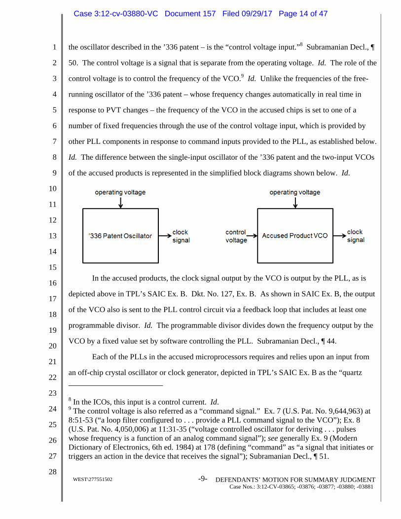
WEST\277551502 -9- DEFENDANTS’ MOTION FOR SUMMARY JUDGMENT Case Nos.: 3:12-CV-03865; -03876; -03877; -03880; -03881
the oscillator described in the ’336 patent – is the “control voltage input.”8 Subramanian Decl., 
50. The control voltage is a signal that is separate from the operating voltage. Id. The role of the
control voltage is to control the frequency of the VCO.9 Id. Unlike the frequencies of the free-
running oscillator of the ’336 patent – whose frequency changes automatically in real time in
response to PVT changes – the frequency of the VCO in the accused chips is set to one of a
number of fixed frequencies through the use of the control voltage input, which is provided by
other PLL components in response to command inputs provided to the PLL, as established below.
Id. The difference between the single-input oscillator of the ’336 patent and the two-input VCOs
of the accused products is represented in the simplified block diagrams shown below. Id.
In the accused products, the clock signal output by the VCO is output by the PLL, as is
depicted above in TPL’s SAIC Ex. B. Dkt. No. 127, Ex. B. As shown in SAIC Ex. B, the output
of the VCO also is sent to the PLL control circuit via a feedback loop that includes at least one
programmable divisor. Id. The programmable divisor divides down the frequency output by the
VCO by a fixed value set by software controlling the PLL. Subramanian Decl., ¶ 44.
Each of the PLLs in the accused microprocessors requires and relies upon an input from
an off-chip crystal oscillator or clock generator, depicted in TPL’s SAIC Ex. B as the “quartz
8 In the ICOs, this input is a control current. Id. 9 The control voltage is also referred as a “command signal.” Ex. 7 (U.S. Pat. No. 9,644,963) at 8:51-53 (“a loop filter configured to . . . provide a PLL command signal to the VCO”); Ex. 8 (U.S. Pat. No. 4,050,006) at 11:31-35 (“voltage controlled oscillator for deriving . . . pulses whose frequency is a function of an analog command signal”); see generally Ex. 9 (Modern Dictionary of Electronics, 6th ed. 1984) at 178 (defining “command” as “a signal that initiates or triggers an action in the device that receives the signal”); Subramanian Decl., ¶ 51.
Case 3:12-cv-03880-VC Document 157 Filed 09/29/17 Page 14 of 47
1
2
3
4
5
6
7
8
9
10
11
12
13
14
15
16
17
18
19
20
21
22
23
24
25
26
27
28
WEST\277551502 -10- DEFENDANTS’ MOTION FOR SUMMARY JUDGMENT Case Nos.: 3:12-CV-03865; -03876; -03877; -03880; -03881
crystal” providing a “reference signal” to the PLL control circuit. See Dkt. No. 127 (SAIC) at 2
(“Plaintiffs contend that each component and signal shown in the Representative Clocking
System is present in each of the Accused Products.”). As TPL explained in its opening appeal
brief to the Federal Circuit, the PLL control circuit “uses this reference signal to set the output of
the oscillator to a specific frequency.” Ex. 5 (TPL Appeal Br.) at 20-21 (emphasis added); see
also Subramanian Decl., ¶ 45. In this regard, to set the output frequency of the VCO that is
output by the PLL, the PLL control circuit performs a “phase checking” function by comparing
the phase of the fixed-frequency reference signal that it receives from the external crystal with the
phase of the divided-down signal that it receives through the PLL’s feedback loop. Ex. 6
(Subramanian Tr.) at 1152:11-1153:3; Ex. 10 (RDX-4.46C). Based upon this comparison, the
PLL control circuit determines whether the PLL’s output frequency must be increased or
decreased so that the phase of the divided-down feedback signal received from the programmable
divisor remains locked to the phase of the fixed-frequency external crystal.10 Id. The PLL
control circuit then adjusts a command signal that is output to the control voltage input of the
VCO to control the VCO’s output frequency to maintain that phase lock. Id. In this way, the
PLL feedback loop compensates for PVT variations to ensure the VCO output frequency is
“locked” to a multiple of the fixed-frequency reference signal from the crystal oscillator.
Subramanian Decl., ¶ 40.
The multiplier by which the PLL multiplies the crystal oscillator fixed-frequency is
defined by the values of the one or more programmable divisors in the PLL. Id. at ¶ 45. For
example, if the crystal oscillator operates at 20 MHz, and the programmable divisor is set to 100,
the PLL control circuity sets the fixed output frequency of the VCO, and thus the fixed output
frequency of the PLL, to the value of 100 times the frequency of the crystal, i.e. 2 GHz (so that
when the 2GHz signal is divided by 100, the resulting divided-down signal of 20 MHz matches
10 For two signals to remain in phase with each other, they must have the same frequency. Thus, ensuring that the phase of one signal remains locked to the phase of another signal ensures that the two signals have the same frequency. Subramanian Decl., ¶ 25.
Case 3:12-cv-03880-VC Document 157 Filed 09/29/17 Page 15 of 47
1
2
3
4
5
6
7
8
9
10
11
12
13
14
15
16
17
18
19
20
21
22
23
24
25
26
27
28
WEST\277551502 -11- DEFENDANTS’ MOTION FOR SUMMARY JUDGMENT Case Nos.: 3:12-CV-03865; -03876; -03877; -03880; -03881
the 20 MHz frequency of the crystal oscillator). Subramanian Decl., ¶ 45; see also Ex. 5 (TPL
Appeal Br.) at 20-21. Accordingly, for any given PLL, the fixed output frequency of the VCO is
a direct mathematical function of the frequency of the crystal oscillator and the values of the
programmable divisors.
For example, in the 65 nm GP2 PLLs used in certain accused Qualcomm chips, the fixed
VCO frequency is defined in Qualcomm documentation by the following mathematical formula:
Fout = FVCO / P, where FVCO = 19.2 MHz * (L+M/N)/R. Ex. 6 (Subramanian Tr.) at 1305:6-
1307:19; Ex. 11 (RX-626C) at QTPL 23688-700, 23703; Ex. 12 (RX-1093C) at LGE800ITC
92239-45; Ex. 10 (RDX-4.119C). In this equation, “Fout” is the PLL’s output frequency,
“FVCO” is the VCO’s output frequency, 19.2 MHz is the frequency of the off-chip crystal, and L,
M, N, R and P are software configurable values for the programmable divisors in the PLL. Id.
Thus, the VCO fixed output frequency is literally a function of the fixed off-chip crystal
frequency and the values of the programmable divisor(s). Similar mathematical formulas define
the relationship between the fixed frequency of the external crystal reference and fixed output
frequency of the VCO in the other accused Qualcomm chips. Ex. 6 (Subramanian Tr.) at 1304:6-
1307:19; see also, e.g., Ex. 13 (RX-618C) at QTPL 13892-93 (45 nm HF PLLs); Ex. 14 (RX-
1051C) at QTPL 13830, 13831-33, Ex. 18 (RX-625C) at QTPL 23325, 23345-50, Ex. 19 (RX-
790C) at LGE800ITC 305019-23, Ex. 20 (RX-796C) at ZTE853TPL 763449, 763366-67 (45 nm
NT PLLs); Ex. 21 (RX-791C) at 853SAMSUNG00065622-23, 65628, Ex. 22 (RX-619C) at
QTPL 14386-87, 14393, 14397-98, Ex. 23 (RX-1007C) at LGE800ITC 307019-20 (28 nm HF
PLLs); Ex. 24 (RX-602C); Ex. 14 (RX-1051C); Ex. 10 (RDX-4.118).11
Similarly, the fixed output frequency of the VCO in the
11 Similar mathematical relationships can also be seen in documentation describing accused products by other manufacturers. See, e.g., Ex. 26 (NINTPLD000000977) at NINTPLD000001016 et seq.; Ex. 28 (NINTPL00032980) at NINTPL00033023; Ex. 27 (NINTPL00033308) at NINTPL00033341.
Case 3:12-cv-03880-VC Document 157 Filed 09/29/17 Page 16 of 47

1
2
3
4
5
6
7
8
9
10
11
12
13
14
15
16
17
18
19
20
21
22
23
24
25
26
27
28
WEST\277551502 -12- DEFENDANTS’ MOTION FOR SUMMARY JUDGMENT Case Nos.: 3:12-CV-03865; -03876; -03877; -03880; -03881
Ex. 25 (RX-693C) at
853SAMSUNG00167077; Ex. 6 (Subramanian Tr.) at 1329:25-1331:2; Ex. 6 (Oklobdzija Tr.) at
966:13-969:17; Ex. 16 (RX-690C) at 853SAMSUNG00167113; Ex. 10 (RDX-4.141C); see also
Ex. 15 (RX-696C) at 853SAMSUNG00167799; Ex. 29 (RX-699C) at 853SAMSUNG0042502;
Ex. 30 (RX-694C) at 853SAMSUNG167095-97; Ex. 53 (RX-702C) at 853SAMSUNG00020160.
. Id. Accordingly, the VCO’s fixed output frequency is
literally a function of the fixed off-chip crystal frequency and the value of the programmable
divisors. Similar formulas define the relationship between the external crystal’s fixed frequency
and the VCO’s fixed frequency in the other accused Samsung chips. Ex. 6 (Subramanian Tr.) at
1329:25-1331:2; Ex. 16 (RX-690C) at 853SAMSUNG00167113; Ex. 30 (RX-694C) at
SAMSUNG00167095; Ex. 6 (Oklobdzija Tr.) at 966:13-969:17.
Because the VCO output frequency in the PLL is a function of the fixed frequency of the
crystal oscillator and the values of the one or more programmable divisors in the PLL, the VCO
output frequency only can be changed to a different fixed frequency by changing the values of the
programmable divisors. Subramanian Decl., ¶ 46; see also Ex. 6 (Subramanian Tr.) at 1329:25-
1331:2; Ex. 6 (Oklobdzija Tr.) at 967:22-970:3. In the accused chips, the value of the
programmable divisor(s) are changed via hardware or software command inputs to set the values
of registers associated with the programmable divisors. For example, the Qualcomm 65nm GP2
PLL may receive command inputs that change the value of registers L, M, N, R and P identified
in the mathematical equation governing the relationship between the VCO and the crystal’s fixed
frequency, thus changing the output frequency to a new fixed frequency. Ex. 6 (Subramanian Tr.)
at 1322:20-1324:4; Ex. 11 (RX-626C) at QTPL 23689; see also Pedrali-Noy Decl., ¶¶ 5-6.
Similarly, the PLLs in the accused Samsung chips
Lee Decl., ¶¶ 15-19; Ex. 6 (Subramanian Tr.) at 1329:25-
Case 3:12-cv-03880-VC Document 157 Filed 09/29/17 Page 17 of 47

1
2
3
4
5
6
7
8
9
10
11
12
13
14
15
16
17
18
19
20
21
22
23
24
25
26
27
28
WEST\277551502 -13- DEFENDANTS’ MOTION FOR SUMMARY JUDGMENT Case Nos.: 3:12-CV-03865; -03876; -03877; -03880; -03881
1331:2; Ex. 6 (Oklobdzija Tr.) at 967:22-970:3; Ex. 16 (RX-690C) at 853SAMSUNG00167120.
Output frequency of the PLLs in other accused chips, such as the accused IBM and Sharp chips,
is similarly fixed unless changed by hardware or software command inputs. Ex. 26
(NINTPLD000000977) at NINTPLD000001016 et seq.; Ex. 28 (NINTPL00032980) at
NINTPL00033023; Ex. 27 (NINTPL00033308) at NINTPL00033341. Other than changes
resulting from such command inputs, the output frequency of the PLL will not change.
Subramanian Decl., ¶ 46; see also Pedrali-Noy Decl., ¶ 10.
III. LEGAL STANDARD FOR SUMMARY JUDGMENT
“The court shall grant summary judgment if the movant shows that there is no genuine
dispute as to any material fact and the movant is entitled to judgment as a matter of law.” Fed. R.
Civ. P. 56(a). The moving party bears the burden of demonstrating the absence of a genuine issue
of material fact. Celotex Corp. v. Catrett, 477 U.S. 317, 323 (1986). Upon such a showing, the
nonmovant must then “come forward with specific facts showing that there is a genuine issue for
trial.” Matsushita Elec. Indus. Co. v. Zenith Radio Corp., 477 U.S. 317, 587(1986).
To defeat a motion for summary judgment, the nonmovant must “do more than simply
show that there is some metaphysical doubt as to the material facts.” Id. at 586. The “mere
existence of some alleged factual dispute between the parties will not defeat an otherwise
properly supported motion for summary judgment,” and a factual dispute is genuine only where
“the evidence is such that a reasonable jury could return a verdict for the nonmoving party.”
Anderson v. Liberty Lobby, Inc., 477 U.S. 242, 247-48 (1986).
IV. SUMMARY JUDGMENT SHOULD BE GRANTED IN THIS CASE
Summary judgment of non-infringement should be granted because two independent and
undisputed facts establish that Defendants’ accused products do not practice the “entire
oscillator” claim limitation. Indeed, TPL stipulated to non-infringement under this Court’s prior
claim construction, to which the Federal Circuit made only a “minor modification” to one aspect
of the construction. The unchanged portion of the construction (based on the Magar disclaimer)
on its own leads to a reaffirmation of TPL’s stipulation of noninfringement and TPL has not
explained how the minor modification to the other aspect of the claim construction (based on the
Case 3:12-cv-03880-VC Document 157 Filed 09/29/17 Page 18 of 47

1
2
3
4
5
6
7
8
9
10
11
12
13
14
15
16
17
18
19
20
21
22
23
24
25
26
27
28
WEST\277551502 -14- DEFENDANTS’ MOTION FOR SUMMARY JUDGMENT Case Nos.: 3:12-CV-03865; -03876; -03877; -03880; -03881
Sheets disclaimer) somehow opens the door to any of its newly hatched, poorly conceived
infringement theories. This is because the accused products’ tightly controlled fixed speed PLL
clocks are precisely the opposite of the variable speed “entire oscillator” clocks of the ’336 patent
that automatically change frequencies in real time as PVT conditions change.12
The Federal Circuit’s claim construction, like this Court’s prior construction, properly
incorporates two distinct negative claim limitations that are based upon TPL’s clear and
unambiguous disclaimers during prosecution to distinguish the Magar and Sheets prior art
references. Tech. Props., 849 F.3d at 1354-60. Specifically, to satisfy the Federal Circuit’s
construction, the accused products must include an oscillator that: (1) “does not require a
command input to change the clock frequency,” and (2) “whose frequency is not fixed by any
external crystal.” Id. at 1360. Neither of these limitations is satisfied by the accused products.
Notably, TPL’s amended infringement contentions against all Defendants are
substantively identical. See Case No. 3:12-cv-03865-VC, Dkt. No. 127 (SAIC); Case No. 3:12-
cv-03876-VC, Dkt. No. 131 (SAIC); Case No. 3:12-cv-03877-VC, Dkt. No. 127 (SAIC); Case
No. 3:12-cv-03880-VC, Dkt. No. 144 (SAIC); Case No. 3:12-cv-03881-VC, Dkt. No. 128
(SAIC). In particular, TPL’s amended contentions are based on its high-level, generalized theory
of operation of PLLs, and not on evidence of the actual operation of any Defendant’s individual
accused products, the accused microprocessors or their PLLs. Id. As a result, TPL’s amended
contentions are not Defendant-specific, product-specific, microprocessor-specific, or PLL-
specific. Id.
A. Disclaimer Based On Sheets
The first disclaimer recited in the Federal Circuit’s construction is that the entire oscillator
“does not require a command input to change the clock frequency.” Tech. Props., 849 F.3d at
1360. This phrase was a “minor modification” to the prior constructions’ use of the phrase
12 Indeed, in the prior ITC Investigation, both the ALJ and the Commission found that the accused products do not practice the “entire oscillator” claim limitation. Ex. 31 (Initial Determination) at 118-132; Ex. 32 (Final Determination) at 27-34.
Case 3:12-cv-03880-VC Document 157 Filed 09/29/17 Page 19 of 47

1
2
3
4
5
6
7
8
9
10
11
12
13
14
15
16
17
18
19
20
21
22
23
24
25
26
27
28
WEST\277551502 -15- DEFENDANTS’ MOTION FOR SUMMARY JUDGMENT Case Nos.: 3:12-CV-03865; -03876; -03877; -03880; -03881
“control signal” to capture the prosecution history disclaimer based on the Sheets prior art
reference. The difference between these two phrases, however, is immaterial.
In the accused products, the alleged “entire oscillators” – i.e., the VCOs incorporated
within PLLs – require a command input to change the clock frequency. As discussed above and
as further established below, PLLs are by design fixed-frequency devices whose VCOs output a
stable and fixed frequency. As TPL conceded in its briefing to the Federal Circuit, the oscillator
in a PLL “is not a free running oscillator, as described in column 17 of the ’336 Patent.” Ex. 5
(TPL Appeal Br.) at 20. Rather, as TPL acknowledged, a PLL generates a “clock signal at a
relatively fixed frequency.” Id. at 20. As established below, while the VCO output frequency
may be changed by changing the values of the programmable dividers within the PLL, a
command input is required to do so.
1. The accused oscillators require a command input to change frequency
a. The accused oscillators output a fixed frequency
TPL’s amended contentions ignore an important and indisputable point: a PLL is the
antithesis of a variable speed clock. By its very nature and design, a PLL outputs a very stable
fixed frequency. Ex. 6 (Subramanian Tr.) at 1213:5-10; Ex. 10 (RDX-4.94C). To achieve this
stability, the PLL precisely controls and fixes its output frequency by continuously comparing
this output against an accurate and fixed reference signal provided by an external crystal or clock
generator. Ex. 6 (Subramanian Tr.) at 1212:23-1213:14; Ex. 10 (RDX-4.94C).
As Defendants’ expert Dr. Subramanian explains, a PLL’s ability to provide a stable fixed
output frequency is analogous to a car’s cruise control, which maintains a car’s speed regardless
of environmental conditions. Ex. 6 (Subramanian Tr.) at 1214:14-19; Ex. 10 (RDX-4.95C). For
example, a cruise control set to maintain a car’s speed at 55 miles per hour will maintain this
fixed speed regardless of whether the car is going uphill, downhill, or on a flat surface. Ex. 6
(Subramanian Tr.) at 1214:21-25. Like a cruise control, the PLL compensates for any PVT
effects on its transistors and circuitry, resulting in a fixed-speed clock like the fixed-speed prior
art discussed in the patent. Id. at 1212:17-1214:25.
Mr. Fish, one of the two named co-inventors on the ’336 patent, confirmed that a fixed-
Case 3:12-cv-03880-VC Document 157 Filed 09/29/17 Page 20 of 47

1
2
3
4
5
6
7
8
9
10
11
12
13
14
15
16
17
18
19
20
21
22
23
24
25
26
27
28
WEST\277551502 -16- DEFENDANTS’ MOTION FOR SUMMARY JUDGMENT Case Nos.: 3:12-CV-03865; -03876; -03877; -03880; -03881
speed PLL
Ex. 33 (RX-167C (Fish Depo.)) at 237:5-14. Leaving no doubt on this issue, Mr. Fish further
confirmed that
Id. at 231:24-232:7; see also id. at 231:12-23
b. Empirical evidence confirms the PLL’s frequency is fixed
To confirm the well-known fact that PLLs output a stable fixed frequency, Dr.
Subramanian oversaw testing that measured the clock speed in some accused microprocessors.
Ex. 6 (Subramanian Tr.) at 1252:1-14; Ex. 10 (RDX-4.103C). These measurements confirm the
PLLs in the accused products do not vary as a function of PVT parameters, but rather output a
stable fixed frequency.
First, with respect to the accused Samsung Exynos 4412 chip, Dr. Subramanian
empirically measured the clock output frequency over a large temperature range, as well as over a
substantial operating voltage range. Ex. 6 (Subramanian Tr.) at 1215:6-23; Ex. 34 (RX-1179C);
Ex. 35 (RX-1181C).13 His results appear in the figure below, where the graph on the left shows
13 Dr. Subramanian mounted the chip on a development board, which was available on the open market and which implemented basic phone functionalities. Ex. 6 (Subramanian Tr.) at 1215:6-17. He used a high-precision and well-calibrated Agilent 53131A frequency counter to characterize the frequency behavior of the chip as a function of temperature or voltage. Id. at 1215:17-1216:8, 1219:8-19 (discussing temperature measurement set-up), 1219:20-25 (same for
Case 3:12-cv-03880-VC Document 157 Filed 09/29/17 Page 21 of 47
1
2
3
4
5
6
7
8
9
10
11
12
13
14
15
16
17
18
19
20
21
22
23
24
25
26
27
28
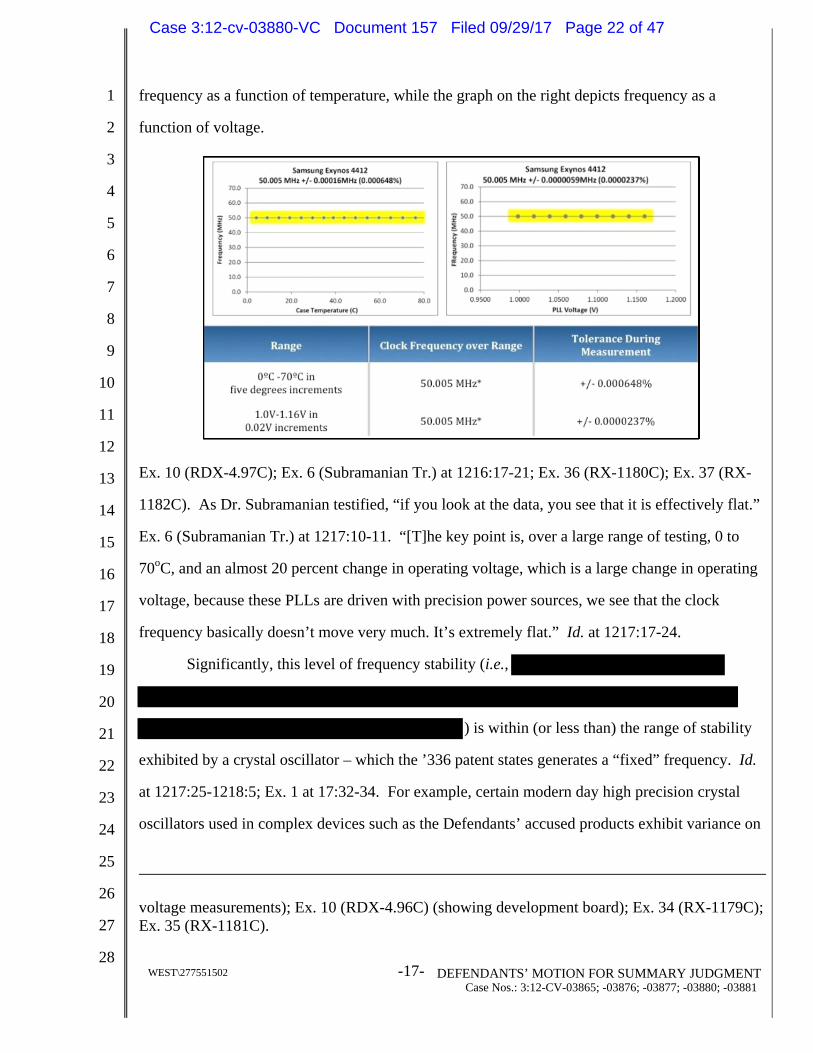
WEST\277551502 -17- DEFENDANTS’ MOTION FOR SUMMARY JUDGMENT Case Nos.: 3:12-CV-03865; -03876; -03877; -03880; -03881
frequency as a function of temperature, while the graph on the right depicts frequency as a
function of voltage.
Ex. 10 (RDX-4.97C); Ex. 6 (Subramanian Tr.) at 1216:17-21; Ex. 36 (RX-1180C); Ex. 37 (RX-
1182C). As Dr. Subramanian testified, “if you look at the data, you see that it is effectively flat.”
Ex. 6 (Subramanian Tr.) at 1217:10-11. “[T]he key point is, over a large range of testing, 0 to
70oC, and an almost 20 percent change in operating voltage, which is a large change in operating
voltage, because these PLLs are driven with precision power sources, we see that the clock
frequency basically doesn’t move very much. It’s extremely flat.” Id. at 1217:17-24.
Significantly, this level of frequency stability (i.e.,
) is within (or less than) the range of stability
exhibited by a crystal oscillator – which the ’336 patent states generates a “fixed” frequency. Id.
at 1217:25-1218:5; Ex. 1 at 17:32-34. For example, certain modern day high precision crystal
oscillators used in complex devices such as the Defendants’ accused products exhibit variance on
voltage measurements); Ex. 10 (RDX-4.96C) (showing development board); Ex. 34 (RX-1179C); Ex. 35 (RX-1181C).
Case 3:12-cv-03880-VC Document 157 Filed 09/29/17 Page 22 of 47

1
2
3
4
5
6
7
8
9
10
11
12
13
14
15
16
17
18
19
20
21
22
23
24
25
26
27
28
WEST\277551502 -18- DEFENDANTS’ MOTION FOR SUMMARY JUDGMENT Case Nos.: 3:12-CV-03865; -03876; -03877; -03880; -03881
the order of 5-10 ppm. Ex. 6 (Subramanian Tr.) at 1483:14-25, 1244:14-1246:21; see also Ex. 6
(Oklobdzija Tr.) at 765:7-12 (describing crystal oscillator variance on the order of 12 ppm).
These modern crystal oscillators produce much more stable frequencies than the crystals available
in 1989, when the ’336 patent was effectively filed, which typically exhibited a variance of 100
ppm. Ex. 6 (Subramanian Tr.) at 1483:14-25. Yet, the ’336 patent described those crystals’
frequencies as “fixed.” Id. For example, the patent contrasts the variable speed oscillator used to
clock the CPU with the “fixed” speed crystal clock used to clock the I/O interface. Ex. 1 at
17:29-34 (describing the “fixed speed” I/O interface), 17:25-27 (describing the I/O interface
speed as being “controlled by a conventional crystal clock 434”). Similarly, during prosecution
of the ’336 patent, the applicants acknowledged that while crystals exhibit minor frequency
variation, they nonetheless are “fixed-frequency” clocks:
Crystals are by design fixed-frequency devices whose oscillation speed is designed to be tightly controlled and to vary minimally due to variations in manufacturing, operating voltage and temperature.
Ex. 3 (’336 patent prosecution history, April 15, 1996 Amendment) at 4; see also Ex. 33 (RX-
167C (Fish Depo.)) at 145:21-24
.
Dr. Subramanian further confirmed the stability of the PLL’s frequency by calculating
tolerance (i.e., the variability associated with the measurements). Ex. 6 (Subramanian Tr.) at
1218:8-10. As shown in the table on RDX-4.97,
Id. at 1218:16-18; Ex. 10 (RDX-4.97C); Ex. 36 (RX-1180C); Ex. 37 (RX-
1182C). Thus, Dr. Subramanian’s measurements demonstrate that the PLL outputs an extremely
stable frequency that is, according to the teaching of the ’336 patent and the understanding of the
’336 patent inventors, fixed.
Second, Dr. Subramanian empirically measured the PLL frequency of the accused
Samsung S5PC210 chip as a function of voltage or temperature by using the same procedure and
set-up used for the Exynos chip. Ex. 6 (Subramanian Tr.) at 1218:22-1219:5, 1220:24-1221:4;
Ex. 10 (RDX-4.98C); Ex. 38 (RX-1183C); Ex. 39 (RX-1185C). As with the Exynos chip, the test
Case 3:12-cv-03880-VC Document 157 Filed 09/29/17 Page 23 of 47

1
2
3
4
5
6
7
8
9
10
11
12
13
14
15
16
17
18
19
20
21
22
23
24
25
26
27
28
WEST\277551502 -19- DEFENDANTS’ MOTION FOR SUMMARY JUDGMENT Case Nos.: 3:12-CV-03865; -03876; -03877; -03880; -03881
data for the S5PC210 chip, as shown in Exhibit 10 (RDX-4.98C), shows no variation over a
temperature range of 0 to 80 degrees Celsius or over a voltage range of 0.95V to 1.20V. Ex. 6
(Subramanian Tr.) at 1220:10-1221:7; Ex. 40 (RX-1184C); Ex. 41 (RX-1186C); Ex. 10 (RDX-
4.99C). And, as with the testing of the Exynos chip, the tolerance for the temperature
measurement was a tiny +/- 0.000592% (
). Id. As Dr.
Subramanian noted, the data “shows that the frequency is essentially flat as a function of
temperature” and “similarly, the frequency is essentially flat as a function of voltage.” Ex. 6
(Subramanian Tr.) at 1220:19-22.
Third, Dr. Subramanian performed measurements on the accused Qualcomm QSC6055
chip as used in an actual phone. This testing, the results of which are depicted in Exhibit 10
(RDX-4.100C), established that the clock frequency was flat as a function of temperature. Ex. 6
(Subramanian Tr.) at 1221:8-1224:2; Ex. 10 (RDX-4.100C); Ex. 42 (RX-1187C); Ex. 43 (RX-
1188C). Because this chip was inside an operating mobile phone, Dr. Subramanian measured the
camera clock frequency as a proxy for the PLL’s output, because this frequency originates from
the same PLL associated with the ARM core. Ex. 6 (Subramanian Tr.) at 1221:22-1222:4; Ex. 24
(RX-602C) at LGE800ITC 1914-16, 1918. The measured camera clock frequency – which is a
fixed fraction of the actual on-chip PLL frequency – was “incredibly flat” over the temperature
range of 0-50 degrees Celsius, with a tolerance of +/-0.000015% (or less than 1 ppm over the
measured temperature range). Ex. 6 (Subramanian Tr.) at1222:25-1223:8; Ex. 42 (RX-1187C);
Ex. 43 (RX-1188C); Ex. 10 (RDX-4.100C).
Finally, Dr. Subramanian measured the frequency output of the PLL in the Qualcomm
MSM8960 chip by using a development board from Qualcomm. Ex. 6 (Subramanian Tr.) at
1224:3-1225:19; Ex. 10 (RDX-4.101C); Ex. 44 (RX-1189C); Ex. 45 (RX-1190C). This
Qualcomm development board provides a terminated output that allows direct measurement of
the PLL frequency without needing a fixed-ratio division as was needed with the other chips. Ex.
6 (Subramanian Tr.) at 1224:13-24. As a result, Dr. Subramanian was able to measure the PLL’s
Case 3:12-cv-03880-VC Document 157 Filed 09/29/17 Page 24 of 47

1
2
3
4
5
6
7
8
9
10
11
12
13
14
15
16
17
18
19
20
21
22
23
24
25
26
27
28
WEST\277551502 -20- DEFENDANTS’ MOTION FOR SUMMARY JUDGMENT Case Nos.: 3:12-CV-03865; -03876; -03877; -03880; -03881
full 1.5 GHz frequency over a large temperature range from 0 to 50 degrees Celsius with a
tolerance of +/- 0.000619% (approximately 6 ppm variation over the measured temperature
range). Id. at 1225:1-10; Ex. 44 (RX-1189C); Ex. 45 (RX-1190C). As shown by the test data
(depicted in RDX-4.101), the PLL’s output was “completely flat” and was “incredibly stable over
the temperature range that we could do.” Ex. 6 (Subramanian Tr.) at 1225:2-4. Indeed, the data
shows that any possible fluctuation was “basically in the range of what the crystal can provide,”
in other words, within what the ’336 patent considers a “fixed” frequency. Id. at 1225:18-19; Ex.
10 (RDX-4.101C); Ex. 44 (RX-1189C); Ex. 45 (RX-1190C). Thus, as the empirical evidence
clearly demonstrates, “the PLL does exactly what it should,” namely, it outputs a frequency that
“does not vary” and “is extremely stable.” Ex. 6 (Subramanian Tr.) at 1226:6-14 see also
Subramanian Decl. ¶¶ 54-69.
In contrast with the fixed frequency output by the PLLs in the accused products, the ’336
patent teaches that the frequency of its claimed variable speed clock will change by as much as
400% due to changes in PVT conditions. Ex. 1 at 17:21-22 (“factor of four”). The ’336 patent
also teaches that the frequency of its claimed clock changes by 100% with changes in temperature
alone, varying from 50 MHz at 70oC to 100 MHz at room temperature (~22oC). Id. at 16:60-63,
17:21-22; Ex. 10 (RDX-4.93C). By contrast, over this same temperature range, Dr.
Subramanian’s empirical measurements showed no detectable variation. Ex. 10 (RDX-4.97-
101C).
In summary, Dr. Subramanian’s empirical testing confirmed that the frequencies output by
the PLLs in the accused products are fixed. TPL never has offered any empirical testing to the
contrary.
c. A command input is required to change the output frequency value of the PLL in the accused products
As established above in Section II.C, the output frequency of the PLL is a function of
frequency of the crystal oscillator and the values of one or more programmable divisors. The
programmable divisors can be programmed to change the output frequency of the PLL.
However, contrary to the Federal Circuit’s construction, the PLL requires a command input to do
Case 3:12-cv-03880-VC Document 157 Filed 09/29/17 Page 25 of 47
1
2
3
4
5
6
7
8
9
10
11
12
13
14
15
16
17
18
19
20
21
22
23
24
25
26
27
28
WEST\277551502 -21- DEFENDANTS’ MOTION FOR SUMMARY JUDGMENT Case Nos.: 3:12-CV-03865; -03876; -03877; -03880; -03881
so.
In the microprocessors in the accused products, the value of the programmable divisor(s)
are changed via commands to set the values of registers associated with the programmable
dividers. Subramanian Decl., ¶¶ 44-46; see also Ex. 6 (Subramanian Tr.) at 1329:25-1331:2; Ex.
6 (Oklobdzija Tr.) at 967:22-970:3. For example, the Qualcomm 65nm GP2 PLL discussed
above receives command inputs that set the value of registers L, M, N, R and P identified in the
mathematical equation governing the relationship between the VCO and the crystal’s frequency,
and the output frequency is changed when those values are changed. Ex. 6 (Subramanian Tr.) at
1322:20-1324:4; Ex. 11 (RX-626C) at QTPL 23689; Ex. 13 (RX-618C) at QTPL 13872-76,
13892-93, 13899-902; Ex. 10 (RDX-4.133C); Ex. 10 (RDX-4.134C) see also Pedrali-Noy Decl.,
¶¶ 5-6. Similarly, the PLLs in the accused Samsung chips receive command inputs
Lee Decl., ¶¶ 15-19; Ex. 6 (Subramanian Tr.) at 1329:25-1331:2;
Ex. 6 (Oklobdzija Tr.) at 967:22-970:3; Ex. 16 (RX-690C) at 853SAMSUNG00167120. Output
frequency of the PLLs in other accused chips, such as the accused IBM and Sharp chips, is
similarly fixed unless changed by hardware or software command inputs. Ex. 26
(NINTPLD000000977) at NINTPLD000001016 et seq.; Ex. 28 (NINTPL00032980) at
NINTPL00033023; Ex. 27 (NINTPL00033308) at NINTPL00033341.
TPL does not appear to dispute that a command input is required to set the value of the
programmable divisors in a PLL. See, e.g., Dkt. No. 127 (SAIC) at 5 (assuming arguendo that
“the writing of a value to the Programmable Divisor on the Feedback Loop of the PLL System is
a ‘command input’…”), 9 (contending that thermal throttling in the accused products infringes
“to the extent that [it] is accomplished by some means other than altering the value of the
Programmable Divisor.”). Indeed, the prior art Sheets reference TPL distinguished during
prosecution of the ’336 patent – on the grounds that the Sheets device required a command input
to change the clock frequency – utilized the same type of command input to control its voltage-
controlled oscillator as do the PLLs in the accused products. Subramanian Decl., ¶ 44.
Case 3:12-cv-03880-VC Document 157 Filed 09/29/17 Page 26 of 47
1
2
3
4
5
6
7
8
9
10
11
12
13
14
15
16
17
18
19
20
21
22
23
24
25
26
27
28
WEST\277551502 -22- DEFENDANTS’ MOTION FOR SUMMARY JUDGMENT Case Nos.: 3:12-CV-03865; -03876; -03877; -03880; -03881
Specifically, Sheets discloses changing frequency of the VCO by writing a “digital word defined
by that frequency… to a register 601.” Ex. 47 (Sheets) at 3:58-61; 4:43-48 (same); Subramanian
Decl., ¶ 44 (a “digital word” is simply a digital value that corresponds to the desired frequency).
In short, a command input in the form of a digital value written to one or more registers in
the accused PLLs is required to change the values of the programmable divisors, which changes
the frequency of the VCO, the alleged “entire oscillator.”
The control voltage signal connected to the control voltage input of the VCO is another
command input required to change the frequency of the VCO. As established above, this signal
directly controls the frequency of the VCO. Section II.C, supra; Subramanian Decl., ¶ 50.
Because the control voltage signal directly controls the frequency of the VCO, this signal must
change in order for the frequency of the VCO to change from one fixed frequency to another
fixed frequency in response to a change in the programmable divider. Id. Additionally, because
the control voltage signal is a command signal, it is a command input. See Ex. 9 (Modern
Dictionary of Electronics, 6th ed. 1984) at 495 (defining “input” as “the current, voltage, power or
other driving force applied to a circuit or device.”); Subramanian Decl., ¶ 51. Thus, the control
voltage is another “command input” that is required to change the frequency of the VCO.
TPL cites no evidence that the frequency of the PLL’s VCO can be changed in any way
other than as decribed above. Accordingly, because the PLL’s VCO requires command inputs to
change the clock frequency, it does not satisfy the Federal Circuit’s construction, which requires
that the entire oscillator “does not require a command input to change the clock frequency.”
2. Each of TPL’s four theoretical infringement theories is meritless
Rather than dismissing its infringement claims in light of the Federal Circuit’s claim
construction and the undisputed operation of the accused products, TPL’s SAIC offers four purely
theoretical contentions regarding how the accused products allegedly might fail to satisfy the
requirement that the entire oscillator “does not require a command input to change the clock
frequency.” Dkt. No. 127 (SAIC) at 4-8. None of these contentions has merit.
Case 3:12-cv-03880-VC Document 157 Filed 09/29/17 Page 27 of 47
1
2
3
4
5
6
7
8
9
10
11
12
13
14
15
16
17
18
19
20
21
22
23
24
25
26
27
28
WEST\277551502 -23- DEFENDANTS’ MOTION FOR SUMMARY JUDGMENT Case Nos.: 3:12-CV-03865; -03876; -03877; -03880; -03881
a. TPL’s theory regarding frequency variations when the PLL is “locked” lacks merit
TPL first contends that changes to the supply voltage, or to the temperature of the chip on
which the PLL is located, will cause the frequency to vary when the PLL is “locked,” and that the
PLL control circuitry will compensate for that variation in order to force the frequency of the PLL
back to the desired frequency. Dkt. No. 127 (SAIC) at 5-7. TPL contends these alleged changes
in frequency do not result from a command input. Id. This argument, however, wholly ignores
the above-cited uncontradicted evidence that any such alleged variations in the frequency of the
VCO in the actual accused products would: (1) be extremely small; (2) fall well within the range
that the ’336 patent and its inventors consider to be a “fixed-frequency”; and (3) bear no
relationship whatsoever to the frequency changes that the ’336 patent describes as occurring in
the claimed variable speed clock as the result of changes in PVT factors. See Section IV.A.1.b,
supra.
Moreover, the tiny variations seen in Dr. Subramanian’s testing are at the precision limit
of the Agilent frequency counter used to conduct these tests. Ex. 6 (Subramanian Tr.) at 1482:14-
15. As Dr. Subramanian explained, “[t]his is all at the precision limit of the instrument. This is
flat.” Id.; see also id. at 1243:1-1244:10, 1481:4-9, 1482:16-23. In light of the instrument’s
detection limit and the microscopic nature of the fluctuations, what appears as a possible variation
of 5-10 ppm for the tested chip may actually reflect no variation at all. Accordingly, as Dr.
Subramanian established, there is no statistically significant variation in the measured PLL output
frequency: “This is statistically flat.” Id. at 1481:4-9. Because there is in fact no meaningful
variation in PLL output frequency as a result of changes in supply voltage or temperature, TPL’s
contention that the frequency output by the PLL varies as a function of these factors lacks merit.
Notably, TPL’s SAIC cites no evidence showing that the frequency output by the VCOs in
the accused products actually varies as a result of operating voltage or operating temperature
changes. Dkt. No. 127 (SAIC) at 5-7. Instead, TPL relies upon a “hypothetical example”
describing the alleged operation of a hypothetical PLL. Id. at 5. While TPL’s “hypothetical
example” accurately describes the manner in which PLL circuitry controls the frequency of its
Case 3:12-cv-03880-VC Document 157 Filed 09/29/17 Page 28 of 47

1
2
3
4
5
6
7
8
9
10
11
12
13
14
15
16
17
18
19
20
21
22
23
24
25
26
27
28
WEST\277551502 -24- DEFENDANTS’ MOTION FOR SUMMARY JUDGMENT Case Nos.: 3:12-CV-03865; -03876; -03877; -03880; -03881
VCO, it greatly overstates (without any support) the magnitude of any alleged VCO frequency
changes in an actual PLL. Subramanian Decl., ¶ 70. Indeed, in its contentions, TPL concedes
that “[i]n actuality, the adjustments [in the hypothetical example]… occur nearly in real time and
may be much smaller in magnitude than described.” Dkt. No. 127 (SAIC) at 6 (emphasis added).
In fact, as established above, Dr. Subramanian’s testing (of which TPL was well aware when it
authored its SAIC) confirms that there is no statistically significant frequency variation in the
accused products. And, to the extent the frequency of the VCO in the accused PLLs may exhibit
tiny frequency variations, these variations are well within the range of the frequency of crystal
oscillators, which the ’336 patent and its inventors consider a “fixed-frequency.”
TPL’s SAIC also contends that the “cumulative adjustments made to the frequency of the
PLL . . . may be in the tens or hundreds of megahertz as the temperature of the Ring Oscillator
changes.” Dkt. No. 127 (SAIC) at 6 (emphasis added). Again, TPL cites no evidence to support
this contention. Id. Moreover, TPL cites no support in either the ’336 patent or the Federal
Circuit’s claim construction that would permit TPL to aggregate any minute frequency changes
that might occur over time to arrive at a “cumulative” total that bears no relationship to any actual
alleged frequency change. In this regard, there is no teaching in the ’336 patent that any tiny
frequency variations that accumulate over a long period of time somehow cumulatively constitute
a frequency variation in response to voltage or temperature changes. See also Subramanian Decl.,
¶¶ 71-74 (confirming that the notion of “cumulative adjustments” is not supported by the ’336
patent or by the understanding of one skilled in the art). In this regard, if one were to accumulate
the frequency variations of a crystal over a long enough time period, one could obtain a
cumulative value in the tens or hundreds of megahertz, but, as established above, the ’336 patent
considers the frequency of a crystal to be fixed within the meaning of the claimed invention. Id.
at ¶ 74.
TPL also relies upon two articles, which TPL contends demonstrate that a VCO in a PLL
necessarily varies in response to changes in supply voltage and temperature. Dkt. No. 127
(SAIC) at 6 (citing SAIC, Ex. D (“Kos article”) and SAIC, Ex. E (“Marin article”)). However,
these articles establish nothing more than that the frequency of the particular VCOs that were the
Case 3:12-cv-03880-VC Document 157 Filed 09/29/17 Page 29 of 47

1
2
3
4
5
6
7
8
9
10
11
12
13
14
15
16
17
18
19
20
21
22
23
24
25
26
27
28
WEST\277551502 -25- DEFENDANTS’ MOTION FOR SUMMARY JUDGMENT Case Nos.: 3:12-CV-03865; -03876; -03877; -03880; -03881
subject of the articles (which are not present in the accused products) varied when there was
nothing in place (such as a PLL) to control the frequency, i.e., “when the control voltage is held
steady” or “without any compensation scheme.” Dkt. No. 127 (SAIC) at 6. These articles are
irrelevant to the application of the asserted patent claims to the accused products. As established
above, the frequency of the VCOs in the accused products is controlled by control circuitry in the
PLLs. See Section II.C, supra; Subramanian Decl., ¶ 76. In rejecting this same argument raised
by TPL, the ALJ in the prior ITC Investigation astutely noted that “[b]y focusing on a theoretical
paper using statistical modeling, Dr. Oklobdzija misses a simple truth, which is that a PLL
compensates for any PVT effects on transistors in order to keep the output frequency stable and
fixed.” Ex. 31 (Initial Determination) at 205 (citing Subramanian Tr. at 1255).
TPL further contends that a PLL “first detects that the frequency has moved outside the
predetermined range, then corrects it.” Dkt. No. 127 (SAIC) at 6. However, TPL offers no
evidence that the PLLs in the accused products actually function by determining whether the
VCO frequency is within a “predetermined range.” Id. And the evidence establishes that they do
not. See, e.g., Pedrali-Noy Decl. ¶¶ 7-9
Lee Decl. ¶¶23-27 (
; Ex. 17 (PLL Manual) at 2-3. Moreover, as established
above, even if TPL were correct, any alleged tiny variation in frequency resulting from any such
“predetermined range” is the type of insignificant variation that the ’336 patent and its inventors
consider fixed.
b. TPL’s infringement theory regarding pre-phase lock frequency variations lacks merit
TPL next contends that frequency variations may occur in a PLL before it is locked to a
desired frequency, either during power up or during a state change (i.e., a change in the value of a
programmable divisor), and that these frequency variations do not require a command input to
change the clock frequency. Dkt. No. 127 (SAIC) at 7. However, any frequency variations
Case 3:12-cv-03880-VC Document 157 Filed 09/29/17 Page 30 of 47

1
2
3
4
5
6
7
8
9
10
11
12
13
14
15
16
17
18
19
20
21
22
23
24
25
26
27
28
WEST\277551502 -26- DEFENDANTS’ MOTION FOR SUMMARY JUDGMENT Case Nos.: 3:12-CV-03865; -03876; -03877; -03880; -03881
during an unlocked state are irrelevant, because in order for such frequency variations to occur, a
command input is required. Start-up does not occur unless a user presses a button, which
necessarily results in a command input to the accused products’ power supply. Subramanian
Decl., ¶ 75. State change also requires a command input be written to a programmable divisor in
the PLL, as established above. See Sections II.C and IV.A.1.c, supra. Because a command input
is required for these alleged frequency variations, they are within the scope of the Sheets
disclaimer.
Furthermore, there is no evidence that the PLLs in accused products are connected to the
CPU or clock the CPU at a clock rate (i.e., a clock frequency) when in an unlocked state. Claims
6 and 13 each recite:
an entire oscillator disposed upon said integrated circuit substrate and connected to said central processing unit, said oscillator clocking said central processing unit at a clock rate
Ex. 1 at claims 6, 13 (emphasis added). TPL offers no evidence that the PLLs in the accused
products are connected to provide clocking signals to the CPU when they are not locked. SAIC at
7. To the contrary, the evidence establishes that the PLLs in at least the Samsung accused
processors . See, e.g., Lee Decl.
¶¶ 20-22; Ex. 15 (RX-696C) at 853SAMSUNG001676 (
.”). Unless a PLL in an unlocked state
is connected to the CPU in the accused products, any frequency variation in an unlocked state is
irrelevant in analyzing whether the claims are practiced because the independent claims expressly
require the entire oscillator to clock the CPU. Ex. 1 at claims 6, 13.
c. TPL’s additional infringement theories regarding variation during phase lock lack merit
TPL next asserts two additional infringement theories regarding alleged variation in VCO
frequency when the PLL is locked. Dkt. No. 127 (SAIC) at 7-8. Neither contention has merit.
First, TPL asserts the frequency of the VCO in a PLL inherently changes in response to
Case 3:12-cv-03880-VC Document 157 Filed 09/29/17 Page 31 of 47

1
2
3
4
5
6
7
8
9
10
11
12
13
14
15
16
17
18
19
20
21
22
23
24
25
26
27
28
WEST\277551502 -27- DEFENDANTS’ MOTION FOR SUMMARY JUDGMENT Case Nos.: 3:12-CV-03865; -03876; -03877; -03880; -03881
changes in PVT, without citing any evidence of the actual operation of the VCOs and PLLs in the
accused products. Id. As established above, the VCO/PLL output frequency in the accused
products does not vary with changes in PVT parameters. See Sections II.C and IV.A.1.a and b,
supra. TPL’s first theory thus lacks merit.
Second, TPL asserts that as a result of the difference between the frequency of the crystal
and the VCO frequency, the VCO in the PLL is “free running” (i.e., not frequency-controlled by
the PLL) for every N-1 clock cycles, where N is the multiplication factor applied by the PLL.
Dkt. No. 127 (SAIC) at 8. TPL further asserts that during these allegedly “free running” periods
of time, the VCO frequency “can change” in response to changes in supply voltage and
temperature. Id.
TPL cites no evidence, empirical or otherwise, in support of this second argument. Id.
The argument is wrong because the control signal from the PLL is being applied to the VCO
during each of the N clock cycles, so the VCO is not “free running” during any of the N clock
cycles. Subramanian Decl. ¶ 76. Moreover, as established above, empirical evidence of the
accused chips in actual operation confirms that the frequency output by the VCO does not change
as a result of voltage and temperature variations. See Sections II.C and IV.A.1.a and b, supra; see
also Subramanian Decl. ¶¶ 54-69. In summary, no evidence supports TPL’s second theory, while
undisputed evidence disproves it.
d. TPL’s “thermal throttling” infringement theory lacks merit
Finally, TPL advances the unfounded theory that the accused products may implement
thermal throttling and that this thermal throttling may be implemented without a command input.
Dkt. No. 127 (SAIC) at 8-9. Specifically, TPL contends that “to the extent that this thermal
throttling is accomplished by some means other than altering the value of the Programmable
Divisor in the PLL,” it falls outside the Sheets disclaimer in the claim construction. Id. at 8. This
speculative theory fails in the first instance because TPL cites no evidence that such thermal
throttling would be implemented using any method other than by command input (i.e., modifying
the values of the programmable divisors in the accused PLLs, which TPL acknowledges would be
non-infringing). Dkt. No. 127 (SAIC) at 8-9.
Case 3:12-cv-03880-VC Document 157 Filed 09/29/17 Page 32 of 47
1
2
3
4
5
6
7
8
9
10
11
12
13
14
15
16
17
18
19
20
21
22
23
24
25
26
27
28
WEST\277551502 DEFENDANTS’ MOTION FOR SUMMARY JUDGMENT Case Nos.: 3:12-CV-03865; -03876; -03877; -03880; -03881
TPL’s contention relies solely on an article describing a Qualcomm smartphone that was
modified to include a thermal throttling algorithm. Id. (citing SAIC, Ex. F (“Coskun article”));
Coskun article at 4 (“Our target experimental platform is a state-of-the-art Qualcomm Snapdagon
MSM8974 smartphone…”), 5 (describing implementation of thermal throttling as a “user-level
[software] program”); Subramanian Decl., ¶ 77. However, the Coskun article provides no basis
to conclude that thermal throttling would be implemented in any way other than by the command
input. Subramanian Decl., ¶ 77. Indeed, the Coskun article describes implementing thermal
throttling by using dynamic voltage frequency scaling (“DVFS”) to change the CPU clock
frequency between several fixed frequencies. See, e.g., Dkt. No. 127 (SAIC), Ex. F (Coskun
article) at 3 (“the CPU can only support discrete DVFS level. We propose a DVFS state
scheduler which … switches between two neighbor frequency levels …”); Subramanian Decl., 
77. Using DVFS to switch between fixed frequency levels is entirely consistent with an
implementation in which the frequency levels are selected by changing the values of a PLLs
programmable dividers. Id. For example, DVFS is a software feature that allows a chip to
“choose what frequency it should run at.” Ex. 6 (Subramanian Tr.) at 1267:11-1270:10; Ex. 10
(RDX-4.110C); Ex. 46 (RX-1817C) at Garmin068424. Because there is a mathematical formula
that defines the output frequency of a PLL as a function of the crystal reference frequency and the
values of programmable dividers, “one can change the frequencies of course by changing the
crystal, but that’s not relevant here. The other way you can change it is by changing the equation
on the PLL … because that has those values L, M, N. You can change those values or any other
dividers values to set the frequency at which a chip runs.” Id. All of these changes require
command inputs, and no evidence suggests DVFS (or thermal throttling) would be implemented
in any other manner.
Furthermore, evidence of the operation of the Qualcomm and Samsung chips confirms
that thermal throttling is implemented by changing the values of programmable dividers. For
example,
Case 3:12-cv-03880-VC Document 157 Filed 09/29/17 Page 33 of 47

1
2
3
4
5
6
7
8
9
10
11
12
13
14
15
16
17
18
19
20
21
22
23
24
25
26
27
28
WEST\277551502 -29- DEFENDANTS’ MOTION FOR SUMMARY JUDGMENT Case Nos.: 3:12-CV-03865; -03876; -03877; -03880; -03881
.14 Pedrali-Noy Decl., ¶ 10. Thermal throttling may also be
implemented by adjusting the values of dividers or pulse swallowers between the PLL and the
CPU in the accused Qualcomm chips, however, adjusting the values of these components does
not result in any change to the frequency of the VCOs within the PLLs (i.e. the alleged entire
oscillators) in the accused Qualcomm chips. Id., ¶ 11. Similarly, in the Samsung accused chips,
thermal throttling is implemented in one of two ways. Lee Decl., ¶¶ 28-31. The frequency of the
clock signal supplied to the CPU may be changed by
. Id., 
29. Alternatively, the frequency of the clock signal may be changed
. Id.; see also Subramanian
Decl., ¶ 43.
B. Disclaimer Based On Magar
The second disclaimer recited in the Federal Circuit’s construction, adopted without
modification from this Court’s construction, is that the entire oscillator is one “whose frequency
is not fixed by any external crystal.” Tech. Props., 849 F.3d at 1359.15 This disclaimer provides
an independent basis for summary judgment. TPL stipulated to noninfringement under this
construction and nothing has changed. As established above, the undisputed design and operation
of the accused products establishes that the frequency of the VCOs within the PLLs in the
accused products is “fixed by an[] external crystal” and, therefore, does not meet the “entire
oscillator” limitation. TPL’s infringement theories to the contrary are both inconsistent with the
14
Pedrali-Noy Decl., ¶ 10. Id.; see also Subramanian Decl. ¶ 46 n. 2.
1 This part of the construction arose from a prosecution history disclaimer in light of a prior art reference to Magar.
Case 3:12-cv-03880-VC Document 157 Filed 09/29/17 Page 34 of 47
1
2
3
4
5
6
7
8
9
10
11
12
13
14
15
16
17
18
19
20
21
22
23
24
25
26
27
28
WEST\277551502 -30- DEFENDANTS’ MOTION FOR SUMMARY JUDGMENT Case Nos.: 3:12-CV-03865; -03876; -03877; -03880; -03881
express language of the claims, and premised upon an erroneous reading of the word “fixed” in
the claim construction, a reading which is inconsistent with (1) the ’336 patent’s specification, (2)
the ’336 patent prosecution history and (3) this Court’s and the Federal Circuit’s rulings.
1. The frequency of the accused oscillators is fixed by an external crystal
As established above, the undisputed operation of PLLs generally and the empirical
evidence of the operation of PLLs in the accused products both confirm that the alleged “entire
oscillators” – i.e. the VCOs within PLLs in the accused products – output a stable fixed
frequency. See Sections II.C and IV.A.1.a and b, supra. This stable output frequency is fixed by
an external crystal used as a reference signal for the PLL. In this regard, it is undisputed that the
PLLs in the accused products require and rely upon an input from an off-chip crystal oscillator or
clock generator. See Dkt. No. 127 (SAIC), Ex. B; see also id. at 10 (“Plaintiffs agree that the
frequency range of Ring Oscillator is determined, in part, by the frequency of the external
crystal.”) . Indeed, as TPL explained in its opening appeal brief to the Federal Circuit, the PLL
control circuit “uses this reference signal to set the output of the oscillator to a specific
frequency.” Ex. 5 (TPL Appeal Br.) at 20-21 (emphasis added); see also Ex. 6 (Subramanian Tr.)
at 1150:4-9, 1151:8-13.
As established above, PLL control circuitry compensates for variations in PVT parameters
to ensure that the VCO output frequency is “locked” to a fixed multiple of the reference signal
from the crystal oscillator. See Sections II.C and IV.A.1.c, supra. The VCO output frequency is
a direct mathematical function of the frequency of the crystal oscillator and programmable
divisors within the PLL. Id. For example, if the crystal oscillator operates at 20 MHz, and the
programmable divisor is set to 100, the PLL control circuity sets the fixed output frequency of the
VCO, and thus the fixed output frequency of the PLL, to the fixed value of 100 times the
frequency of the crystal, i.e. 2 GHz. Id.; Subramanian Decl., ¶ 45.
Because the VCO output frequency is fixed to a predetermined multiple of the external
crystal oscillator frequency used as a reference signal, the VCO output frequency is fixed by the
crystal oscillator. Indeed, both parties’ experts agree that a change in the crystal oscillator
frequency will necessarily result in a change in the VCO output frequency. For example,
Case 3:12-cv-03880-VC Document 157 Filed 09/29/17 Page 35 of 47

1
2
3
4
5
6
7
8
9
10
11
12
13
14
15
16
17
18
19
20
21
22
23
24
25
26
27
28
WEST\277551502 -31- DEFENDANTS’ MOTION FOR SUMMARY JUDGMENT Case Nos.: 3:12-CV-03865; -03876; -03877; -03880; -03881
Defendants’ expert, Dr. Subramanian, explained that because there is a mathematical formula that
defines the output frequency of a PLL as a function of the crystal reference frequency and the
values of programmable dividers, “one can change the frequencies of course by changing the
crystal” or by changing the value of the programmable dividers. Ex. 6 (Subramanian Tr.) at
1267:11-1270:10. Similarly, TPL’s expert, Dr. Oklobdzija, conceded that there is a clear
relationship between the VCO’s output frequency and the crystal’s reference frequency:
Q. Now, you understand that there’s a relationship between the frequency of the reference signal from the crystal and the frequency at the output of the VCO?
A. Yes, there is a relationship, which is established by the divider. So if it divides by 100, the relationship is 1 to 100.
Ex. 6 (Oklobdzija Tr.) at 834:12-18; see also id. 835:20-21. Specifically, if the external crystal’s
frequency goes up, the VCO’s frequency will also go up by a fixed ratio. Id. at 836:1-8. If the
reference frequency goes down, so will the VCO’s frequency. Id. at 836:9-19. As Dr. Oklobdzija
explained, “the output frequency would be changed if the input frequency changes. That’s what
PLL does.” Id. at 967:18-21; see also id. 953:17-25.
2. TPL’s infringement theories are meritless
Ignoring all of the above-described evidence establishing non-infringement, TPL’s SAIC
proffers vaguely worded contentions as to how the accused products allegedly meet the claim
construction’s requirement that the entire oscillator is one “whose frequency is not fixed by any
external crystal.” Dkt. No. 127 (SAIC) at 9-10. Both arguments are wrong.
a. TPL’s theory that the accused oscillators are “inherently variable” is incorrect
TPL first contends, without citation to any evidence, that the frequency of the VCOs in the
accused products is “inherently variable” and is “never fixed (by anything).” Dkt. No. 127
(SAIC) at 9 (emphasis in original); see also id. at 10 (at lines 16-20) (ring oscillators “are by
nature, inherently variable in response to PVT and are never fixed”). TPL further argues that “a
Ring Oscillator requires only a supply voltage to oscillate, and thus adjustments are made by
regulating voltage” (id. at lines 19-20). However, as established above, the frequency output by
Case 3:12-cv-03880-VC Document 157 Filed 09/29/17 Page 36 of 47

1
2
3
4
5
6
7
8
9
10
11
12
13
14
15
16
17
18
19
20
21
22
23
24
25
26
27
28
WEST\277551502 -32- DEFENDANTS’ MOTION FOR SUMMARY JUDGMENT Case Nos.: 3:12-CV-03865; -03876; -03877; -03880; -03881
the VCOs in the PLLs of the accused products are stable and fixed, and do not change in response
to changes in supply voltage (as distinct from the control voltage) as TPL alleges. See Sections
II.C and IV.A.1, supra. Thus, to the extent that TPL is contending that ring oscillators, in
isolation, are in theory free-running, that is not the case in the accused products, in which the
VCOs are a tightly integrated part of a PLL system that precludes such frequency variation. Id.
b. TPL is incorrect that the PLL’s controlled frequency changes satisfy the Court’s claim construction
TPL correctly notes that the accused products can operate at different frequencies. Dkt.
No. 127 (SAIC) at 9-10. TPL also correctly notes that a change in frequency is accomplished in
part by changing the values of the programmable divisors in the PLL. Id. at 10 (at lines 13-15);
see also Sections II.C and IV.A.1.c, supra. TPL also vaguely points to the alleged (and
unproven) minute frequency fluctuations that are discussed above in connection with the Sheets
disclaimer. Dkt. No. 127 (SAIC) at 10 (at lines 21-22). TPL concludes from this that the PLL
oscillator frequencies are not “fixed” and, therefore, that they satisfy the claim construction. Dkt.
No. 127 (SAIC) at 10 (at lines 4-10). This assertion is wrong for at least two fundamental
reasons.
(1) TPL’s contention regarding intentional frequency changes by the PLL is incorrect
TPL contends that the VCO output frequency in the accused products is not “fixed” within
the meaning of the claim construction because the frequency may be switched from one fixed
frequency to another fixed frequency by “altering the value of the Programmable Divisor.” Dkt.
No. 127 (SAIC) at 10. This contention is without merit because it is at odds with the asserted
claims, which are not directed to just any kind of changes in oscillator frequency, but rather are
specifically directed to an oscillator whose frequency varies as a function of PVT parameters.
Intentional changes to the oscillator frequency from one fixed frequency to another fixed
frequency that are caused by a command input that changes the values of the Programmable
Divisor rather than changes in PVT parameters falls outside the asserted claims, both because it is
within the Sheets disclaimer and because it does not satisfy the limitation requiring frequency
variation that is a function of PVT parameters.
Case 3:12-cv-03880-VC Document 157 Filed 09/29/17 Page 37 of 47

1
2
3
4
5
6
7
8
9
10
11
12
13
14
15
16
17
18
19
20
21
22
23
24
25
26
27
28
WEST\277551502 -33- DEFENDANTS’ MOTION FOR SUMMARY JUDGMENT Case Nos.: 3:12-CV-03865; -03876; -03877; -03880; -03881
As established in Section II.B above, the purported invention of the ’336 patent is a
variable speed oscillator whose frequency is “determined by the parameters of temperature,
voltage, and process” so that “its performance tracks the parameters which similarly affect all
other transistors on the same silicon die.” Ex. 1 (’336 patent) at 16:59-67; see Section II.B,
supra. The requirement that the frequency of the “entire oscillator” vary with and be caused by
changes in PVT parameters is embodied in the express language of the asserted independent
claims. Ex. 1 at claim 6 (claiming “varying” the “clock rate” of the entire oscillator “as a
function of parameter variation in one or more fabrication or operational parameters associated
with said integrated circuit substrate, thereby enabling said [CPU] processing frequency to track
said [entire oscillator] clock rate in response to said parameter variation”), claim 13 (same).
In contrast, altering the value of programmable dividers in the accused products is an
intentional change in the clock frequency from one fixed frequency to another fixed frequency
and is unrelated to changes in PVT parameters. Subramanian Decl., ¶ 44; see also Section II.C
and IV.A.1.a, b and c, supra. In this regard, Dr. Subramanian has explained that the PLL’s use of
the crystal oscillator in the accused products is similar to a car’s cruise control. Ex. 6
(Subramanian Tr.) at 1212:17-1214:25. The cruise control can, for example, keep the car’s speed
fixed at 55 miles per hour, despite (and not as a result of) variations in environmental conditions
(e.g., going uphill or downhill) that otherwise would alter the speed. Id. But, nothing prevents
the cruise control from then being used to change the speed of the car intentionally from 55 to 65
miles per hour, and then to maintain that second fixed speed. Subramanian Decl., ¶¶ 52-53.
Similarly, the crystal oscillator in the accused products is used in conjunction with the PLL to fix
the output frequency of the VCO at a selected one of a number of fixed frequencies that is a
multiple of the fixed frequency of the external crystal oscillator, and any change from one such
fixed frequency to another fixed frequency is not a variance in oscillator frequency that is a
function of PVT variation as the claims require. See Sections II.C and IV.A.1.a, b and c, supra.
Accordingly, the alleged “entire oscillators” in the accused products have a “fixed” frequency
within the meaning of the disclaimer in the Court’s claim construction and, therefore, do not
satisfy the “entire oscillator” limitation.
Case 3:12-cv-03880-VC Document 157 Filed 09/29/17 Page 38 of 47
1
2
3
4
5
6
7
8
9
10
11
12
13
14
15
16
17
18
19
20
21
22
23
24
25
26
27
28
WEST\277551502 -34- DEFENDANTS’ MOTION FOR SUMMARY JUDGMENT Case Nos.: 3:12-CV-03865; -03876; -03877; -03880; -03881
(2) TPL’s interpretation of “fixed” is incorrect
TPL’s arguments also are premised on its “interpretation” of the word “fixed” in the claim
construction as meaning the oscillator frequency never can change or fluctuate. Dkt. No. 127
(SAIC) at 10 (defining “fixed” as “‘not fluctuating or varying,’ ‘definite,’ or ‘predetermined and
not subject to or able to be changed.’”). This “interpretation” of “fixed” is indisputably wrong.
Specifically, in the patentee’s own words, a fixed frequency is one “designed to be tightly
controlled and to vary minimally due to variations in manufacturing, operating voltage and
temperature.” Ex. 2 (File History, July 3, 1997 Amendment) at 4 (emphasis added). The VCOs
within PLLs in the accused products – which TPL contends satisfy the “entire oscillator”
limitation – are tightly controlled and vary minimally due to variations in manufacturing,
operating voltage and temperature. See Sections II.C and IV.A.1. and b, supra. These accused
devices are thus “fixed” frequency devices under the patentee’s own definition. TPL’s newly-
concocted contrary interpretation of “fixed” must be rejected as it contradicts the ’336 patent
specification, the prosecution history, and this Court’s claim construction order and the Federal
Circuit’s opinion.
(a) TPL’s interpretation of “fixed” is inconsistent with the specification
TPL’s newly-concocted interpretation of “fixed” is antithetical to the very point of the
’336 patent claims. As established in Section II.B above, the stated purpose of the claimed
invention is to do away with any external influence on clock frequency – such as the use of an
external crystal. Instead, the ’336 patent would allow the oscillation frequency be “determined by
the parameters of temperature, voltage, and process” so that “its performance tracks the
parameters which similarly affect all other transistors on the same silicon die.” Ex. 1 (’336
patent) at 16:59-67; see Section II.B, supra. For that reason, the ITC soundly rejected TPL’s
argument that the VCOs in the accused products are “variable” as opposed to “fixed”:
The teaching of the specification is antithetical to allowing outside influences to affect the clock rate of the on-chip oscillator, which is how prior art microprocessors operated. Rather, the specification explicitly teaches precisely the opposite, that the use of external sources for timing was inefficient and that the solution is to allow the clock rate of the oscillator to vary solely due to the same parameters that are affecting the operational efficiency of the remainder of the on-
Case 3:12-cv-03880-VC Document 157 Filed 09/29/17 Page 39 of 47

1
2
3
4
5
6
7
8
9
10
11
12
13
14
15
16
17
18
19
20
21
22
23
24
25
26
27
28
WEST\277551502 -35- DEFENDANTS’ MOTION FOR SUMMARY JUDGMENT Case Nos.: 3:12-CV-03865; -03876; -03877; -03880; -03881
chip components, e.g., the CPU. As such, the specification of the ’336 patent does not allow for the on-chip oscillator to be influenced by some outside source, e.g., an external crystal such as is used in a PLL, which, by definition, isolates the clock rate of the on-chip oscillator from the effects of the chip’s PVT parameters.
Ex. 32 (Commission Opinion) at 18-19 (emphasis added).
Having lost at the ITC, TPL now seeks a do-over. But, just as the ITC concluded, the use
of an external crystal in a PLL – such as in the accused products – “by definition, isolates the
clock rate of the on-chip oscillator from the effect of the chip’s PVT parameters.” (Id.) Thus, the
accused products are precisely the kinds of devices with which the ’336 patent contrasted its
invention. In fact, rather than being isolated from the effects of PVT variations, the ’336 patent
specification teaches that the speed of the claimed variable speed clock “may vary by a factor of
four depending upon temperature, voltage, and process.” Ex. 1 at 17:21-22. The ’336 patent
specification also teaches that, although an external crystal clock should be used to control the
speed of the I/O interface, it should be “decoupl[ed]” from “the variable speed of the CPU” in
order to achieve “optimum performance.” Id. at 17:25-34. This is opposite to the operation of
the accused products. The external crystal in defendants’ products is not “decoupled” from the
CPU and there is no variation in clock speed due to variations in PVT.
(b) TPL’s interpretation of “fixed” is inconsistent with its statements during prosecution
TPL’s interpretation of “fixed” also contradicts numerous statements made by the
applicants during prosecution to obtain the ’336 patent. For example, in response to the
examiner’s rejection over Magar, the patentee distinguished its application by asserting that “the
clock disclosed in the Magar reference is in fact driven by a fixed frequency crystal, which is
external to the Magar integrated circuit.” Ex. 2 (File History, July 3, 1997 Amendment) at 2.
Yet, TPL’s interpretation of “fixed” would exclude the minor frequency variations exhibited by a
Case 3:12-cv-03880-VC Document 157 Filed 09/29/17 Page 40 of 47
1
2
3
4
5
6
7
8
9
10
11
12
13
14
15
16
17
18
19
20
21
22
23
24
25
26
27
28
WEST\277551502 -36- DEFENDANTS’ MOTION FOR SUMMARY JUDGMENT Case Nos.: 3:12-CV-03865; -03876; -03877; -03880; -03881
“fixed frequency” crystal.16 Thus, TPL’s new interpretation of “fixed” would now expand the
claims to encompass the disclaimed device disclosed in Magar because—according to TPL—the
minor frequency variations exhibited by Magar’s external crystal would mean that the Magar
fixed-frequency crystal is somehow not a fixed-frequency device.
Similarly, during prosecution, the applicants asserted that even if the crystal in Magar
were entirely on the chip it still would not practice the claimed invention because, although the
frequency of the crystal would “vary minimally due to variations in manufacturing operating
voltage and temperature,” the variations would be “tightly controlled” and would “not vary due to
variations in manufacturing, operating voltage and temperature in the same way as the frequency
capability of the microprocessor on the same underlying substrate.” Ex. 2 (File History, July 3,
1997 Amendment) at 4 (emphasis added). TPL therefore clearly disclaimed any chip for which
the clock frequency “var[ied] minimally,” but where the variance was “tightly controlled” and
was not due to PVT variations. Id. Here, other than the intentional changes in PLL frequency
that are discussed above and fall outside of the scope of the claims, any alleged variances in the
frequency of the VCO in the PLLs in the accused products would be “minimal,” and all frequency
changes in the PLL are “tightly controlled” and do not arise from variations in PVT parameters.
See Sections II.C and IV.A.1. b and c, supra. Thus, TPL now seeks to redefine “fixed” in a
manner that is directly inconsistent with the manner in which it described a “fixed” frequency
device during prosecution.
Finally, the applicants distinguished Magar by asserting that in the ’336 patent “the speed
of the CPU and the clock vary together due to manufacturing variation, operating voltage and
temperature of the IC,” whereas in Magar “the speed of the CPU and the clock do not vary
together due to manufacturing variation, operating voltage and temperature of the IC.” Ex. 2
(File History, July 3, 1997 Amendment) at 3 (emphasis in original). Yet, TPL now contorts the
16 As established above, the minor frequency variations that TPL asserts exist in the VCOs in the accused products are equal to or less than the frequency variations exhibits by crystal oscillators. See Section IV.A.1.b, supra.
Case 3:12-cv-03880-VC Document 157 Filed 09/29/17 Page 41 of 47

1
2
3
4
5
6
7
8
9
10
11
12
13
14
15
16
17
18
19
20
21
22
23
24
25
26
27
28
WEST\277551502 -37- DEFENDANTS’ MOTION FOR SUMMARY JUDGMENT Case Nos.: 3:12-CV-03865; -03876; -03877; -03880; -03881
meaning of “fixed” to assert the claims cover chips for which TPL concedes that an external
crystal “keep[s] the frequency of the Ring Oscillator within a predetermined range as conditions
surrounding the Ring Oscillator change.” Dkt. No. 127 (SAIC) at 5. Contrary to the claims and
teachings of the ’336 patent, TPL now seeks to cover chips in which “the speed of the CPU and
the clock do not vary together due to manufacturing variation, operating voltage and temperature
of the IC,” despite distinguishing Magar on that very ground. Ex. 2 (File History, July 3, 1997
Amendment) at 3 (emphasis in original).
Because TPL’s interpretation of “fixed” in the claim construction is inconsistent with
what it told the PTO during prosecution to distinguish the Magar prior art reference, it cannot be
correct. Southwall Techs., Inc. v. Cardinal IG Co., 54 F.3d 1570, 1576 (Fed. Cir. 1995) (“Claims
may not be construed one way in order to obtain their allowance and in a different way against
accused infringers.”); Computer Docking Station Corp. v. Dell, Inc., 519 F.3d 1366, 1379 (Fed.
Cir. 2008) (a patentee “cannot recapture claim scope disavowed during prosecution to prove
infringement”).
(c) TPL’s reading of “fixed” is inconsistent with this Court’s and the Federal Circuit’s rulings
TPL’s interpretation of “fixed” is also inconsistent with the part of this Court’s claim
construction order that addressed the Magar disclaimer, in which the Court construed “entire
oscillator” as including the disclaimer “whose frequency is not fixed by any external crystal.”
Dkt. No. 104 at 2, 4-6, 10. The Federal Circuit adopted this portion of the claim construction
without modification. Dkt. No. 111; Tech. Props., 849 F.3d at 1359.
Judge Grewal’s Recommendation supported the inclusion of this disclaimer in the claim
construction by explaining that the applicants had “disclaimed use of an external crystal to cause
clock signal oscillation.” Dkt. No. 104 at 5. Similarly, Judge Grewal explained that the patentee
had emphasized “that the claimed invention did not rely on an external crystal’s fixed frequency
to set the clock’s frequency rate.” Id. The Federal Circuit’s opinion likewise states that one
aspect of the applicants’ Magar disclaimer was “that the ‘entire oscillator’ cannot require an
external crystal,” and that, among their many disclaiming statements about Magar, applicants said
Case 3:12-cv-03880-VC Document 157 Filed 09/29/17 Page 42 of 47
1
2
3
4
5
6
7
8
9
10
11
12
13
14
15
16
17
18
19
20
21
22
23
24
25
26
27
28
WEST\277551502 -38- DEFENDANTS’ MOTION FOR SUMMARY JUDGMENT Case Nos.: 3:12-CV-03865; -03876; -03877; -03880; -03881
Magar taught a frequency controlled by an external crystal, and that Magar relied on an external
crystal to oscillate. Tech. Props., 849 F.3d at 1359. Thus, the disclaimer “whose frequency is not
fixed by any external crystal” should exclude products that make use of an external crystal to
oscillate or to set the clock’s frequency.
In its SAIC, TPL concedes that “the frequency range of” the oscillators in the accused
products “is determined, in part, by the frequency of an external crystal.” Dkt. No. 127 (SAIC) at
10. This is confirmed by the above-described, undisputed operation of the PLLs in the accused
products. See Sections II.C and IV.A.1. b and c, supra. Thus, the accused “entire oscillators”
require an external crystal and rely on an external crystal’s fixed frequency to set the clock
frequency’s rate. The frequency of the alleged “entire oscillators” is, therefore, “fixed by an
external crystal,” and, accordingly, the “entire oscillator” limitation is not satisfied.
V. CONCLUSION
There is no genuine dispute that Defendants’ products produce clock signals at a
frequency that is fixed by an external crystal and can be changed only by command inputs. For
each of these independent reasons, Defendants request that the Court grant summary judgment of
non-infringement as to all asserted claims. Dated: September 29, 2017 DLA PIPER LLP (US)
/s/ Mark D. Fowler Mark D. Fowler (SBN 124235) Aaron Wainscoat (SBN 218337) Erik R. Fuehrer (SBN 252578) 2000 University Avenue East Palo Alto, CA 94303 Tel. (650) 833-2000 Fax (650) 833-2001 James M. Heintz (pro hac vice) 11911 Freedom Dr. Reston, VA 20190 Tel. (703) 733-4000 Fax (703)733-5000 Robert C. Williams (SBN 246990) 401 B Street, Suite 1700
Case 3:12-cv-03880-VC Document 157 Filed 09/29/17 Page 43 of 47

1
2
3
4
5
6
7
8
9
10
11
12
13
14
15
16
17
18
19
20
21
22
23
24
25
26
27
28
WEST\277551502 -39- DEFENDANTS’ MOTION FOR SUMMARY JUDGMENT Case Nos.: 3:12-CV-03865; -03876; -03877; -03880; -03881
San Diego, California 92101 Tel. (619) 699-2700 Fax (619) 699-2701 Attorneys for Defendants SAMSUNG ELECTRONICS CO., LTD. and SAMSUNG ELECTRONICS AMERICA, INC. MCDERMOTT WILL & EMERY LLP /s/ Charles M. McMahon MCDERMOTT WILL & EMERY LLP Charles M. McMahon (pro hac vice) [email protected] Hersh H. Mehta (pro hac vice) [email protected] 444 West Lake Street Chicago, IL 60606 [Tel.] (312) 372-2000 [Fax] (312) 984-7700 Fabio E. Marino (SBN 183825) [email protected] L. Kieran Kieckhefer (SBN 251978) [email protected] 275 Middlefield Road, Ste. 100 Menlo Park, CA 94025 [Tel.] (650) 815-7400 [Fax] (650) 815-7401 Attorneys for Defendants, ZTE CORPORATION and ZTE (USA) INC.
STEPTOE & JOHNSON LLP
/s/ Timothy C. Bickham Timothy C. Bickham Steptoe & Johnson LLP 1330 Connecticut Avenue, NW Washington, DC 20036 Telephone: (202) 429-5517 Facsimile: (202) 429-3902 Attorneys for Defendants HUAWEI TECHNOLOGIES CO., LTD., HUAWEI DEVICE CO., LTD., HUAWEI DEVICE USA INC., FUTUREWEI TECHNOLOGIES, INC., and HUAWEI TECHNOLOGIES USA INC.
Case 3:12-cv-03880-VC Document 157 Filed 09/29/17 Page 44 of 47

1
2
3
4
5
6
7
8
9
10
11
12
13
14
15
16
17
18
19
20
21
22
23
24
25
26
27
28 WEST\277551502 -40- DEFENDANTS’ MOTION FOR SUMMARY JUDGMENT
Case Nos.: 3:12-CV-03865; -03876; -03877; -03880; -03881
FISH & RICHARDSON P.C.
/s/ Scott A. Elengold Michael J. McKeon, pro hac vice [email protected] Christian A. Chu (CA SBN 218336) [email protected] Richard A. Sterba, pro hac vice [email protected] Scott A. Elengold, pro hac vice [email protected] FISH & RICHARDSON P.C. McPherson Building 901 15th Street, N.W., 7th Floor Washington, D.C. 20005 Tel. (202) 783-5070 Fax: (202) 783-2331
Olga I. May (CA SBN 232012) [email protected] FISH & RICHARDSON P.C. 12390 El Camino Real San Diego, CA 92130 Tel. (858) 678-4745 Fax: (858) 678-5099
Attorneys for Defendants LG ELECTRONICS, INC. and LG ELECTRONICS USA. INC.
COOLEY LLP
/s/Matthey J. Brigham Cooley LLP Matthew J. Brigham (SBN 191428) [email protected] 3175 Hanover Street Palo Alto, CA 94304-1130 Tel.: (650) 843-5000 Fax: (650) 849-7400
Stephen R. Smith (pro hac vice) [email protected] 1299 Pennsylvania Ave., NW Suite 700 Washington, DC 20004 COOLEY LLP Tel.: (703) 456-8000 Fax: (703) 456-8100
Attorneys for Defendants
Case 3:12-cv-03880-VC Document 157 Filed 09/29/17 Page 45 of 47
1
2
3
4
5
6
7
8
9
10
11
12
13
14
15
16
17
18
19
20
21
22
23
24
25
26
27
28 WEST\277551502 -41- DEFENDANTS’ MOTION FOR SUMMARY JUDGMENT
Case Nos.: 3:12-CV-03865; -03876; -03877; -03880; -03881
NINTENDO CO., LTD and NINTENDO OF AMERICA INC.
Case 3:12-cv-03880-VC Document 157 Filed 09/29/17 Page 46 of 47

1
2
3
4
5
6
7
8
9
10
11
12
13
14
15
16
17
18
19
20
21
22
23
24
25
26
27
28 WEST\277551502 -42- DEFENDANTS’ MOTION FOR SUMMARY JUDGMENT
Case Nos.: 3:12-CV-03865; -03876; -03877; -03880; -03881
ATTESTATION
I, Scott A. Elengold, am the ECF User whose ID and password are being used to file
Defendants’ Case Management Statement. In compliance with Civil Local Rule 5-1(i)(3), I
hereby attest that the signatories listed above have read and approved the filing of this brief.
/s/ Scott A. Elengold Scott A. Elengold, pro hac [email protected] & RICHARDSON P.C.McPherson Building901 15th Street, N.W., 7th FloorWashington, D.C. 20005Tel. (202) 783-5070Fax: (202) 783-2331
Case 3:12-cv-03880-VC Document 157 Filed 09/29/17 Page 47 of 47


![[vc 1037 - listing.archiviolocation.com · [vc 1037] ARCHIVIOLOCATION.COM [vc 1037] ARCHIVIOLOCATION.COM [vc 1037] ARCHIVIOLOCATION.COM [vc 1037] ARCHIVIOLOCATION.COM. archivio location](https://img.dokumen.tips/doc/110x75/5fcd99d1df347e1ae154645c/vc-1037-vc-1037-archiviolocationcom-vc-1037-archiviolocationcom-vc-1037.jpg)