Embed Size (px)
Citation preview
Advanced Controller for Robot Manipulator
Jwu-Sheng HuProfessor, Dept. of Electrical and Computer Engineering, NCTU, TaiwanTechnical Director, MSL, ITRI, TaiwanDirector, Intelligent Robotics Division, MSL, ITRI, Taiwan

Outline
• Advanced Robot Arm• Real-time OS• EtherCat Protocol • Robotic Arm Dynamic Control Technology• 3D Objects Pose Estimation • Intelligent Graphic User Interface System• Advanced Hand-Eye-Workspace Calibration

Advanced Robot Arm• Designed and assembled by Industrial
Technology Research Institute.• Small and compact size• Seven degree of freedom

Advanced Robot Arm
• EtherCAT communication• No control box, and the motor
driver is embedded in each link.• Hollow shaft design for routing
Outline
• Advanced Robot Arm• Real-time OS• EtherCat Protocol • Robotic Arm Dynamic Control Technology• 3D Objects Pose Estimation • Intelligent Graphic User Interface System• Advanced Hand-Eye-Workspace Calibration

Real-time OSIntroduction
• Growing penetration of Linux• OSS EtherCAT has been developed• Control applications in user space is possible
– IgH version 1.5.0 or above
• However,– IgH can’t guarantee RT capability– Even RTAI is adopted

Real-time OSIgH EtherCAT
• IgH EtherCAT is composed of– master module
• Provide functions and data structures to allow applicationsaccessing the master functionalities via API
– control application• Interface with the master modules by means of API• For the cyclic exchange of process data with EC slaves• Can be implemented with IgH EC libraries

Real-time OSCereia’s Work
• “A user space EtherCAT master architecturefor hard real-time control systems ”• 2012 IEEE ETFA Conference
• Implementation• Linux kernel 2.6.32.11 + RTAI 3.8.1• IgH 1.5.0
• Improve the user space control application• Modify the control application to be RTAI tasks• Make it to reach real-time capability

Real-time OSDrive via Character Device

Real-time OSJitter: Kernel vs. User Space

Real-time OSCharacter Device vs. Shared Memory

Real-time OSJitter: User Space/Cereia’s Design
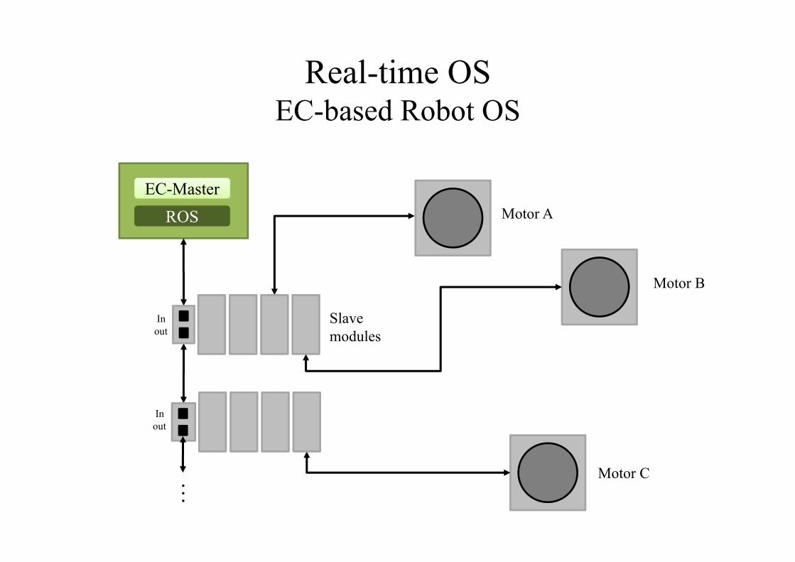
Real-time OSEC-based Robot OS
ROSEC-Master
Inout
Inout
Motor A
Motor B
Motor C
Slavemodules
…

Real-time OSConclusion
• Control application can be implemented at user space based on RTAI• Real time guaranteed
• Cereia’s Design can be used to realize a Robot OS• For real-time control

Outline
• Advanced Robot Arm• Real-time OS• EtherCat Protocol • Robotic Arm Dynamic Control Technology• 3D Objects Pose Estimation • Intelligent Graphic User Interface System• Advanced Hand-Eye-Workspace Calibration
EtherCat ProtocolOutline
• Industrial Communication Technique Comparison• COE Communication Structure
• Cyclic Data Transmission• Acyclic Data Transmission
• EtherCAT Master Processing Procedure• Device Description File
• Device Description File Analysis• Package Analysis• Establish Motion Control Parameters
• EtherCAT Master User Interface Demo
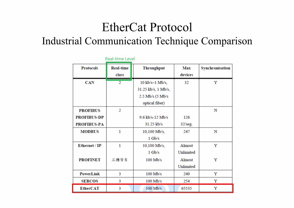
EtherCat ProtocolIndustrial Communication Technique Comparison

EtherCat ProtocolCOE Communication Structure
COE(CANopen Over EtherCAT) includes the followingcommunication mode:(1) Mailbox mode – Use SDO (Service Data Object) for acyclictransmission.(2) Buffer mode – Use PDO (Process Data Object) for cyclictransmission.

EtherCat ProtocolCOE Communication Structure
• Acyclic Data Transmission(Mailbox mode)When the sender writes the buffer, the buffer is locked for writing until the receiver has read it out.

EtherCat ProtocolCOE Communication Structure
• Cyclic Data Transmission(Buffer mode)The sender can always update the content of the buffer. If the buffer iswritten faster than it is read out by the receiver, old data is dropped.Thus, the receiver always gets the latest consistent buffer contentwhich was written by the sender.

EtherCat ProtocolEtherCAT Master Processing Procedure
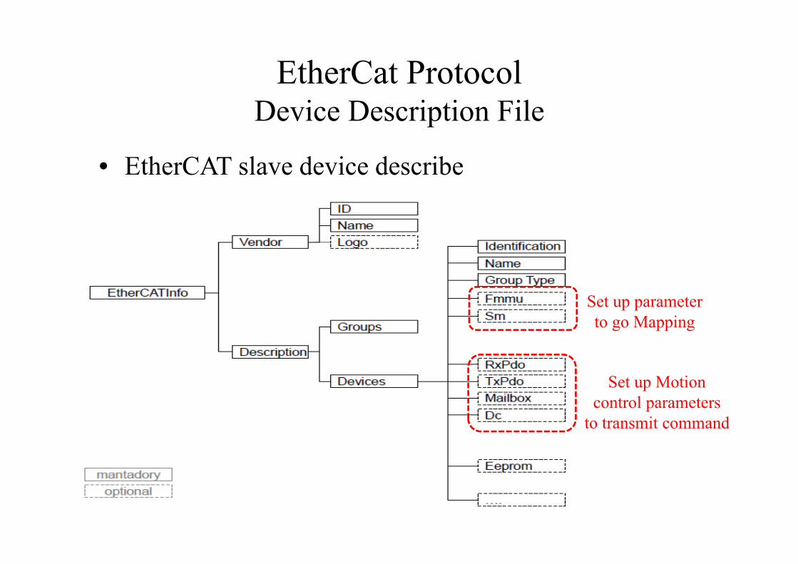
EtherCat ProtocolDevice Description File
• EtherCAT slave device describe
Set up parameter to go Mapping
Set up Motion control parameters
to transmit command

EtherCat ProtocolDevice Description File
• Device description file analysis
Mapping physical address

EtherCat ProtocolDevice Description File
• Package analysis
Master Logical Address
Slave Physical Address
9 μs
2.002ms

EtherCat ProtocolDevice Description File
• Establish motion control parameters• When controller parameter is used, it musts set up.• Using handshake mechanism makes sure whether
National Chiao Tung University
Slave addr : Slave node , offset addr : Physical address
CANopen over EtherCAT
EtherCat ProtocolEtherCAT Master User Interface Demo
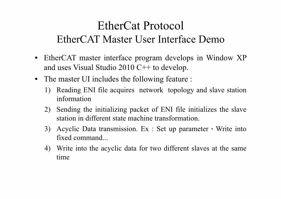
• EtherCAT master interface program develops in Window XPand uses Visual Studio 2010 C++ to develop.
• The master UI includes the following feature :1) Reading ENI file acquires network topology and slave station
information2) Sending the initializing packet of ENI file initializes the slave
station in different state machine transformation.3) Acyclic Data transmission. Ex : Set up parameter、Write into
fixed command...4) Write into the acyclic data for two different slaves at the same
time

EtherCat ProtocolEtherCAT Master User Interface Demo

Outline
• Advanced Robot Arm• Real-time OS• EtherCat Protocol • Robotic Arm Dynamic Control Technology• 3D Objects Pose Estimation • Intelligent Graphic User Interface System• Advanced Hand-Eye-Workspace Calibration

Robotic Arm Dynamic Control TechnologyIntroduction
• We develop high-precision, high-response-speedmulti-axis control laws for 7-dof robotic arm. Thecontrol laws are robust, not affected by the change ofthe load arm. We regulate the control parameters withsystematic rule.

Robotic Arm Dynamic Control TechnologyKinematics
• Forward kinematics:We use D-H model to get the end-effector pose correspondingto angle of each axis. We transfer joint-space coordinate intoCartesian coordinate.
Joint θ (degree)
a d
1 θ1 -90 0 D12 θ2 90 0 03 θ3 -90 0 D3 4 θ4 90 0 D4 5 θ5 -90 0 D5 6 θ6 90 0 07 θ7 0 0 D7
DH Parameters

Robotic Arm Dynamic Control TechnologyKinematics
X0, X1 , X2
X5 , X6 , Xt
X3
X4
Z1
Z0,Z2
Z3
Z4
Z5
Z6 , Zt
D1
D3
D5
D7
D4
GND

Robotic Arm Dynamic Control TechnologyKinematics
• Inverse kinematics: We calculate angle of each axis by the position of end-effector.We transfer Cartesian coordinate into joint-space coordinate.The verification through 3D simulation are shown as follow:

Robotic Arm Dynamic Control TechnologyDynamic Equations
Robotic arm robot arm dynamic equations describe therelationship between position, velocity, acceleration andtorque, which can be expressed as the following formula:
where θ is the rotation angle of each axis, M( ) is themass inertia matrix, C( , ) is the centripetal force andthe Coriolis force matrix, the above two matrices are 7 ×7 matrix, G( ) is the 7×1 gravity vector, τ is the torqueof each axis from the actuator.

Robotic Arm Dynamic Control TechnologyDynamic Equations
• Newton-Euler equation and the Euler-Lagrangeequation are common methods to derive dynamicequations. We represent length, mass, inertia andcentroid location of robotic arm as symbols throughMATLAB symbolic toolbox, and then derive thedynamic equations by the Newton-Euler equation andEuler-Lagrange equation, respectively, to get M ,C , G . After verification, the τ derived by theNewton-Euler equation and by the Euler-Lagrangeequation are matched.

Robotic Arm Dynamic Control TechnologyCurrent Loop System Identification
• Accelnet Plus driver provides position, velocity andcurrent mode. Due to that current is proportional totorque, the dynamic control is implemented using thecurrent mode. In order to determine whether we need tocompensate or not, we have to get the frequency responseof the current loop of the servo motor.
The driver control loop block diagram

Robotic Arm Dynamic Control TechnologyCurrent Loop System Identification
• The process of the system identification is as follows: 1) Set the parameters of current loop controller (PI controller's Kp,
Ki)2) Input different frequency of sinusoidal current command to
motor by CME2, respectively, and record the magnitude andphase of input and output current to plot bode plot.
3) Combine the input current command and output current in stepb, and identify the system by using MATLAB identificationtoolbox.
4) Input the test sinusoidal command to the model from step 3,and then compare the model output with the actual modeloutput to verify the result of identification.

Robotic Arm Dynamic Control TechnologyExperimental Result
• DC brushless motor: KBM-10H01-C00• Digital servo drive: Accelnet Plus Module EtherCAT
AEM-090-14• Absolute encoder: DS-58[20] (18 bits Angular resolution)
• Obtained model:

Robotic Arm Dynamic Control TechnologyExperimental Result
• Comparing the bode plot of models and servo motoras follows:
-2
0
2
Mag
nitu
de (d
B)
100
101
102
103
-30-25-20-15-10
-505
Pha
se (d
eg)
Bode Diagram
Frequency (Hz)
modelmotor
motormodel
Bode plot of models and servo motor

Robotic Arm Dynamic Control TechnologyExperimental Result
• Input the sinusoidal test command and compare theoutputs of the model and the motor.
0 0.01 0.02 0.03-1
-0.5
0
0.5
1
Time
Measured and simulated model output
modelmotor
6 8 10
x 10-3
0.6
0.8
1
Time
0 0.002 0.004 0.006 0.008 0.01-1
-0.5
0
0.5
1
Time
Measured and simulated model output
modelmotor
1.5 2 2.5 3 3.5
x 10-3
0.5
0.6
0.7
0.8
0.9
1
Time
100HZ 300HZ

Robotic Arm Dynamic Control TechnologyFuture Work
• Solve the singularity problem of 7-axis JacobianMatrix.
• Build the process of robot arm system identificationto identify the parameters of dynamic model.
• Develop high efficiency motion control law of robotarm.

Outline
• Advanced Robot Arm• Real-time OS• EtherCat Protocol • Robotic Arm Dynamic Control Technology• 3D Objects Pose Estimation • Intelligent Graphic User Interface System• Advanced Hand-Eye-Workspace Calibration

3D Objects Pose Estimation Outline
• Introduction• Problem Statement• CAD Database system• Hand-Eye Calibration• Experimental Result• Conclusion and Feature Work

3D Objects Pose Estimation Introduction
• With the advent of new-generation depth sensors,using 3D data is becoming increasingly popular. Asthese sensors are commodity hardware and sold atlow cost, a rapidly growing group of people canacquire 3-D data cheaply and in real time.
• For a texture-less object like a mechanical part,conventional visual feature matching usually failsdue to the absence of rich texture features.
• The vision system is easily set up to recognizedifferent objects by using CAD models database.

3D Objects Pose Estimation Problem Statement
• How to carefully chosen feature descriptorencode more information compactly andthereby provide higher accuracy 6-DOF poseestimation and enable faster computation.
• How to use CAD data to establish the CAD-model database, so that the system not onlywork even in highly cluttered environment, butalso to accurately estimate 6-DOF pose of theworkpieces.

System Architecture

3D Objects Pose Estimation 6-DOF Pose Estimation System
• The system can convert scene depth image to point cloud format,and estimate the 6-DOF pose of object by using CAD Databasewhich has been established in offline phase.
Scene Depth Image
Convert to Scene Point Cloud
Boundary Estimation Voxel Grid Filter Random Sample
Filter
Compute B2B pair feature descriptor
ClusteringPose Refinement Using ICP Matching
6-DOF Pose Estimation System
6-DOF Pose of objectCAD
Database
3D Objects Pose Estimation 6-DOF Pose Estimation System
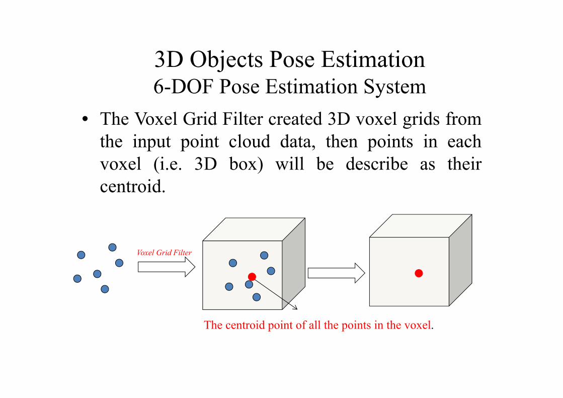
• The Voxel Grid Filter created 3D voxel grids fromthe input point cloud data, then points in eachvoxel (i.e. 3D box) will be describe as theircentroid.
The centroid point of all the points in the voxel.
Voxel Grid Filter

3D Objects Pose Estimation Voting-Scheme Matching
,
Hash Table
+1
+1
Accumulator Space
(1) Reference point Sr is paired with every other point Si, and their point pair feature F iscalculated.(2) Feature F is matched to the hash table, which returns a set of point pairs on the modelthat have similar distance and orientation.(3) For each point pair on the model matched to the point pair in the scene, the localcoordinate is calculated by solving .(4) After is calculated, a vote is cast for the local coordinate

3D Objects Pose Estimation Pose Clustering
• The retrieved poses are clustered such that allposes in one cluster do not differ in translation androtation for more than a predefined threshold.
• The score of a cluster is the sum of the scores ofthe contained poses, after finding the cluster whichvote is bigger than threshold, the resulting pose iscalculated by averaging the poses contained in thecluster.
_ _ _ _
=> pose_n is put in cluster_n
_
=> cluster_n is final pose estimation

3D Objects Pose Estimation Eye-in-Hand Calibration
• We set up an eye-in-handconfiguration using the Kuka6-DOF robot arm installedwith a Kinect camera.
• We first calibrated the eye-in-hand configuration byusing the DLR CameraCalibration Toolbox.

3D Objects Pose Estimation Calibration Result
• We took 15 images of the calibration pattern withvarying orientations and translation. The errormeans are 2.54 mm, 7.99mm and 2.74mm in x-coordinate, y-coordinate and z-coordinate,respectively.

3D Objects Pose Estimation Experimental Result

3D Objects Pose Estimation Conclusion and Feature Work
• The 6-DOF object pose estimation based onCAD-model database has been proposed.
• We have implemented the 6-DOF poseestimation system in kuka robot. Theexperimental result shown that the proposedmethod can pick 3-4 bins in one minute.
• In the feature, we will speed up the cycle timeof the method.
Outline
• Advanced Robot Arm• Real-time OS• EtherCat Protocol • Robotic Arm Dynamic Control Technology• 3D Objects Pose Estimation • Intelligent Graphic User Interface System• Advanced Hand-Eye-Workspace Calibration

Intelligent Graphic User Interface SystemGoal
• The graphic user interface system is developedfor operating an industrial robotic arm, withthe implementation on the tablet of an Androidbased application.
• The graphic user interface system:
• Providing a more ease-to-use virtual interface forthe operator to execute the task.
• Providing a platform to realize the remote control.
Intelligent Graphic User Interface SystemCommunication
• The WiFi technology makes it possible for usto control robot remotely, while tablet makes itpossible for us to control the robot in the visualinterface.
• The programming based on TCP WindowsSockets is used to realize the communication.– TCP Windows Sockets:
• A reliable transport protocol• Ordered• Streaming
Intelligent Graphic User Interface SystemCommunication
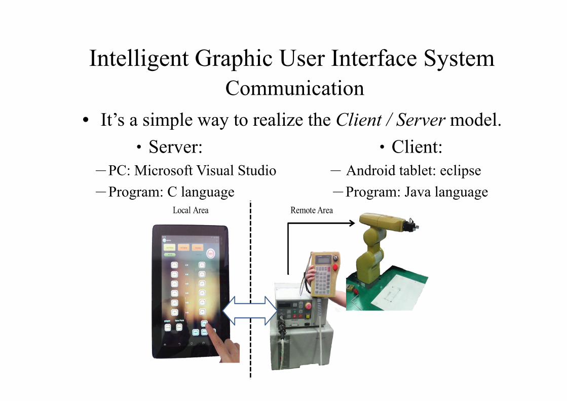
• It’s a simple way to realize the Client / Server model.‧Server: ‧Client:
-PC: Microsoft Visual Studio - Android tablet: eclipse-Program: C language -Program: Java language

Intelligent Graphic User Interface SystemCommunication
PC:The program uses multi-threads.
Multi-thread is the ability of a program to manage multiple requests at one time in the computer.
send data
Tablet PC
send data
send data
Tablet PC
send data
receive data
receive data
Multi-ThreadSingle-Thread

Intelligent Graphic User Interface SystemSpecifications
• Tablet– ASUS Memo Pad FHD ME302KL-1B024A– Qualcomm 8064 Quad-core 1.5GHz– OS:Android4.2– Size:264 x 182 x 9.5mm– LCD size:10.1-inch IPS– WiFi、Bluetooth

Intelligent Graphic User Interface SystemOperation Interface
• Tablet– Joint Mode
Connection button
Mode-selected button
Joint buttons
Joint information
Viewing angle buttonsGripper button
Save points button
Intelligent Graphic User Interface SystemOperation Interface
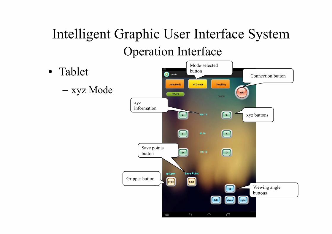
• Tablet– xyz Mode
Connection button
Mode-selected button
xyz buttons
xyz information
Viewing angle buttons
Gripper button
Save points button

Intelligent Graphic User Interface SystemOperation Interface
• Tablet– Teach Mode Menu of Points
Run buttons

Intelligent Graphic User Interface SystemOperation Interface
• Tablet– Knob Mode
Joint buttons
Knob
Seekbar to adjust the scale of the knob

Intelligent Graphic User Interface SystemDemo

Outline
• Advanced Robot Arm• Real-time OS• EtherCat Protocol • Robotic Arm Dynamic Control Technology• 3D Objects Pose Estimation • Intelligent Graphic User Interface System• Advanced Hand-Eye-Workspace Calibration
Advanced Hand-Eye-Workspace CalibrationIntroduction
• The proposed Hand-Eye-Workspace calibrationsystem including a laser pointer installed on therobot arm, a stationary camera, and a planarsurface. The laser pointer beams to the surface,and the camera observes the projected laser spot.It is not necessary for robot arm to enter the viewscope of the camera for calibration. Theconfiguration of camera is more flexible.

• CHB: The transformation matrixbetween the fixed camera andthe robot base. It represents thecamera extrinsic matrix.
• BHE: The transformation matrixbetween the robot base and theend-effector. It represents therobot kinematics.
• The relationship between thelaser pointer and the end-effector.
• Plane equation• Camera intrinsic parameters
Advanced Hand-Eye-Workspace CalibrationDefinition

Advanced Hand-Eye-Workspace CalibrationDefinition
The laser line is defined in theend-effector coordinate with twoposition parameters (y, z) and twoEuler angles (, ). The values offour parameters are unique. Thedirection of line is computed with(, ) as
,
cos sin sin sin cos
E E EL L L
TE E E E EL L L L L
u

Advanced Hand-Eye-Workspace CalibrationLine-Plane Intersection
• Laser lineThe laser line in the camera coordinate can be obtainedusing CHB , BHE and . The direction isdenoted as Czlaser . The position is denoted as Cplaser.
• Plane definitionA plane is generally described by the normal vector nand the position vector p of any point on the plane, but itcan be simply defined by the unique position vectorwhose direction is the normal vector as
, if 0( ) otherwise
n n pa
n p n
, , ,E E E EL L L Ly z
Advanced Hand-Eye-Workspace CalibrationLine-Plane Intersection
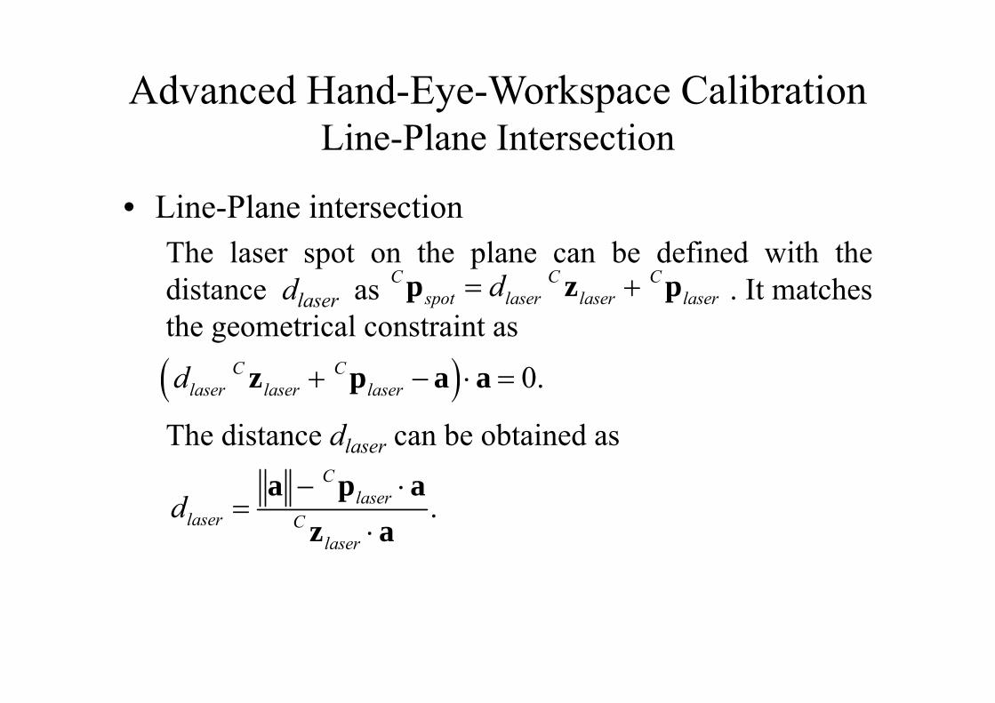
• Line-Plane intersectionThe laser spot on the plane can be defined with thedistance dlaser as . It matchesthe geometrical constraint as
The distance dlaser can be obtained as
C C Cspot laser laser laserd p z p
.C
laserlaser C
laser
d
a p az a
0.C Claser laser laserd z p a a

Advanced Hand-Eye-Workspace CalibrationCamera Model
• The camera model is a pin-hole type including lensdistortion. The 2D position (u ,v) in an image of a 3Dpoint Cp =[Cx, Cy, Cz]T can be obtained with theintrinsic matrix K and the lens distortion parameters(1, 2, 1, 2) as
0
0 with 01 1 0 0 1
d u c u
d v
u x f f uv y f v
K K

Advanced Hand-Eye-Workspace CalibrationCamera Model
• The camera model is a pin-hole type including lensdistortion. The 2D position (u ,v) in an image of a 3Dpoint Cp =[Cx, Cy, Cz]T can be obtained with theintrinsic matrix K and the lens distortion parameters(1, 2, 1, 2) as
where is the raydirection from the camera.
2 2
2 4 1 21 2 2 2
1 2
2 ( 2 )1
( 2 ) 2r r r rd
r r rd r r r r
x y xxy y x y
xx x x
x
TT C C C Cr r rx y x z y z x

Advanced Hand-Eye-Workspace CalibrationAll Parameters
• CHB: The transformation matrix between the fixed cameraand the robot base. It is defined with the Euler angles
and the position .• BHE: The transformation matrix between the robot base
and the end-effector. The robot kinematic parameters.• The relationship between the laser pointer and the end-
effector is defined with Euler angles and theposition .
• Plane equation : a• Camera intrinsic matrix K and the lens distortion parameters
(1, 2, 1, 2)
, ,B B BC C C B
Ct
,E EL L
ELt

Advanced Hand-Eye-Workspace CalibrationExperiment
• For Hand-Eye-Workspace calibration, the goal is toestimate the relationship between the robot arm, thecamera and the workspace plane. Assuming the robotarm and the camera are pre-calibrated. The estimatedparameters include– and : the transformation matrix
between the fixed camera and the robot base.– and : the relationship between the laser
pointer and the end-effector.– a : the plane parameters.
, ,B B BC C C B
Ct
,E EL L E
Lt

Advanced Hand-Eye-Workspace CalibrationExperiment
Experiment Configuration

Advanced Hand-Eye-Workspace CalibrationExperiment
• The robot arm, Stäubli TX60, is operated to generatemultiple laser spots on the plane in the view of camera.The measurement is the (u ,v) position of laser spot. Theoptimal solution is obtained by minimizing the totalposition errors using nonlinear optimization method (theLevenberg-Marquardt method).
• The laser spot position in the image is obtained by twosteps. First, the grey image converts to binary imageusing the simple threshold method. It can reject the imagenoise. Second, the average position of light pixels is thelaser spot position.

Advanced Hand-Eye-Workspace CalibrationExperiment
Parameter 30 samples 50 samples
Unit Initialized Refined Refined
( BC , B
C , BC ) (-100.14, -3.29, -172.69) (-102.55, -6.15, -174.22) (-102.60, -5.88, -173.53) degree
B TCt [1343.73, -4.34, 319.28] [965.56, -47.41, 440.90] [976.59, -38.35, 436.62] mm
( EL , E
L ) (-89.93, 80.21) (-91.15, 84.45) (-91.13, 84.36) degree E TL t [0, -30.14, 423.31] [0, 8.55, 135.06] [0, 7.49, 140.77] mm
Ta [-70.39, 55.95, 690.76] [-50.57, 35.52, 705.07] [-61.34, 33.18, 702.78] mm
RMS 30.32 1.0626 1.1494 pixel
Calibration Result

Advanced Hand-Eye-Workspace CalibrationConclusion
• The proposed calibration system is cost-efficient andflexible for any manipulator. It can be extended tocalibrate the camera intrinsic parameters and thekinematic parameters of robot arm.