Embed Size (px)
Citation preview

CARPENTER'SAND
JOINER'SHAND-BOOK.


THE
CAEPEUTEE'S AND JOINER'S
HAND-BOOK:CONTAININCr
A COMPLETE TREATISE ON FRAMINGHIP AND VALLEY ROOFS.
TOGETHER WITS
MUCH VALUABLE INSTRUCTION FOR ALL MECHANICS ANDAMATEURS, USEFUL RULES, TABLES, ETC.,
. NEVER BEFORE PUBLISHED.
REVISED EDITION WITH ADDITIOm.
BY
PRACTICAL ARCHITECT AND BUILDER,
AUTHOR OF
«'THE ART OF SAW-FILING."
ILLUSTRATED BY FORTY-THREE ENGRAVINGS.
NEW YORK :
JOHN WILEY & SONS,15 AsTOR Place.
1882,

Entered according to Act of Congress, ih the year 1863,
By H. W. holly,
the Clerk's Office of the District Court of the United States for
the District of Connecticut.
PEEFACE.
This work has been undertaken by tbe
antlior to supply a want long felt by tlie
trade : that is, a cheap and convenient
"Pocket Guide/' containing the most use-
ful and necessary rules for the carpenter.
The writer, in his progress " through the
mill," has often felt that such a work as this
would have been of great value, and some
one principle here demonstrated been worth
many times the cost of the book.
It is believed, therefore, that this book will
commend itself to those interested, for the
reason that it is cheap, that it is plain and
easily understood, and that it is useful.

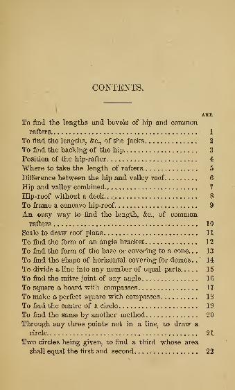
CONTENTS.
ART.
To find the lengths and bevels of hip and commonrafters 1
To find the lengths, &c., of the jacks 2
To find the backing of the hip , 3
Position of the hip-rafter 4
"Where to take the length of rafters 5
Difference between the hip and valley roof 6
Hip and vaUey combined 7
Hip-roof without a deck. . .-^ 8
To frame a concave hip-roof 9
An easy way to find the length, &c., of commonrafters 10
Scale to draw roof plans 11
To find the form of an angle bracket 12
To find the form of the base or covering to a cone. . . 13
To find the shape of horizontal covering for domes .
.
' 14
To divide a line into any number of equal parts 15
To find the mitre joint of any angle 16
To square a board with compasses lY
To make a perfect square with compasses 18
To find the centre of a circle 19
To find the same by another method 20
Through any three points not in a line, to draw a
circle 21
Two circles being given, to find a third whose area
shall equal the first and second 22

6 CONTENTS.
ART.
To find the form of a raking crown moulding 23
To lay out an octagon from a square 24
To draw a hexagon from a circle 25
To describe a curve by a set triangle 26
To describe a curve by intersections 2t
To describe an elliptical curve by intersection of
lines 28
To describe the parabolic curve 29
To find the joints for splayed work 30
Stairs 31
To make the pitch-board 32
To lay out the string 33
To file the fleam-tooth saw 34
To dovetail two pieces of wood on four sides 35
To splice a stick without shortening 36
The difference between large and small files 3t
Piling wood on a side-hill 38
Another mysterious splice 39
To find the height of a tree 40
To cut bridging to fit 41
Building fence over a hill 42
To draw an oval with a string 43
To find the speed of shafting 44
To glue mitre and butt joints 45
To find the number of gallons in a tank 46
To find the area of a circle 47
Capacity of wells and cisterns 48
Weights of various materials 49
THE CARPENTER'S AND JOINER'S
HAND-BOOK-
HIP AND YALLEY EOOES.
The framing of liip and valley roofs, being
of a different nature from common square
rule framing, seems to be understood by
very few. It need scarcely be said, that it is
very desirable tbat this important part of a
carpenter's work should be familiar to
every one who expects to bes.rated as a first-
class workman. The system here shown is
proved, by an experience of several years,
to be perfectly correct and practicable;and,
as it is simple and easily understood, it is
believed to be the best in use. Care has
been taken to extend the plates so as to de-

THE carpenter's
monstrate eacli position or principle by it-
self, so that the inconvenience and confusion
of many lines and letters mixed np with
each other may be avoided.
Article 1.
—
Tofind the lengths andhevels
of hijp and common rafters.
'hetppp (Fig. 1) represent the face of the
plates of the building;d^ the deck-frame
:
HAND-BOOK. 9
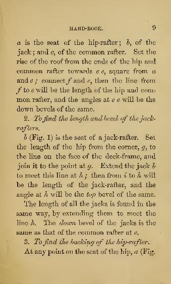
a is the seat of the hip-rafter; 5, of the
jack ; and of the common rafter. Set the
rise of the roof from the ends of the hip and
common rafter towards e square from a
and G / connect/* and then the line from
ftoe will be tlie length of the hip and com-
mon rafter, and the angles at ^ ^ will be the
down bevels of the same.
2. Tojmd the length and hevel of thejaclc-
raftei's,
h (Fig. 1) is the seat of a jack-rafter. Set
the length of the hip from the corner, to
the line on the face of the deck-frame, and
join it to the point at g. Extend the jack h
to meet this line at h / then from i to h will
be the length of the jack-rafter, and the
angle at h will be the top bevel of the same.
The length of all the jacks is found in the
same way, by extending them to meet the
line A. The dovm bevel of the jacks is the
same as that of the common rafter at e.
3. Tofind the hacking of the hip-rafter.
At any point on the seat of the hip, a (Fig.

10 THE carpenter's
1), draw a line at right angles to extending
to the face of the plates ^thh j upon the
points where the lines cross, draw the half
circle, just touching the Ymefej connect the
point aty, where the half circle cuts the line
a, with the points hh j the angle formed at^'
will be the proper backing of the hip-rafter.
It is not worth while to back the hip-raf-
ter unless the roof is one-quarter pitch or
. more.
4. It is always desirable to have the hip-
rafters on a mitre line, so that the roof will
all be the same pitch ; but when for some
reason this cannot be done, the same rule is
employed, but the jacks on each side of the
hip are different lengths and bevels.

HAND-BOOK. 11
Fig. 2.
The heavy line from d (Fig. 2), shows the
seat of the hip-rafter ; a and the jacks. Set
the rise of the roof at e / set the length of
the hip d from d to/* on one side of the
deck, and from 6? to ^ on the other side ; ex-
tend the jack J, and all the jacks on that
side, to the line df^ for the length and top
bevels ; extend the jack and all on that
side, to the line d for the length and bevels
on that side of the hip. The down bevels
of the jacks will be the same as that of the
common rafters on the same side of the
roof.

12 THE carpenter's
5. The lengths of hips, jacks, and valley-
rafters should be taken on the centre line, and
the thickness or half thickness allowed for.
(See Fig. 3.)
Fig. 3.
6. The valley-roof is the same as the hip-
roof inverted. The principle of construction
is the same, with a little different applica-
tion.

HAND-BOOK. 13
Fig. 4.
Let a h (Fig. 4) represent the valley-rafter;
jj are corresponding jack-rafters. Set the
rise of the roof from a to c / connect h and
c : from 5 to ^ is the length of the valley-
rafter, and the angle at g the bevel of the
same ; set the length h c on the line from
extend the jack^ to meet the line b d at e ;
then from etof is the length of the jack,
and the angle at e the top bevel of the same.
7. When the hip and valley are combined^

14 THE carpenter's
SO that one end of the jack is on the hip^ and
the other on the valley.
Fig. 5.
a h (Fig. 5) is the hip, and c d the valley-
rafters. Find the length of each according
to the previous directions ; find the lines e
andf as before.
Extend the jacks j j to the line e^ for the
top bevel on the hip : extend the same on
the other end to the line/*, for the top bevel
on the valley ; the whole lengths of the jacks

HAND-BOOK. 15
is from the line/* to the line e. If the hip
and valley rafters lie parallel, the bevel will
be the same on each end of the jack.
8. In framing a hip-roof without a deck-
ing or observatory, a ridge-pole is nsed, and
of such a length as to bring the hip on a
mitre line ; but this ridge-pole must be cut
half its thickness longer at each end, or the
hip will be thrown out of place and the
whole job be disarranged.
This is illustrated by the figure. Suppose
the building to be 16 by 20, the ridge would
require to be four feet long ; but if the stick
is four inches thick, for instance, then it
7

i
16 THE carpenter's
should be cut four feet four inches long, so|
that the centre line on the hip, will point'
to the centre of the end of the ridge-pole,\
J, at four feet long. This simple fact is often\
overlooked. •
9. To frame a concave hip-roof,—(This]
is much used for verandas, balconies, sum-;
mer-houses, &c.) •
P
Fig. T. J
To find the curve of the hip.\ \
Let a (Fig. 7) be the common rafter in its\
true position, the line h being level. Draw the|
i
i

HAiSTD-BOOK. 17
line c on the angle the hip-rafter is to lie,
generally a mitre line ; draw the small lines
0^ parallel to the plate The more ofthese
lines, the easier to trace the cnrve ; continue
the lines o o where they strike the line c
square from that line ; set the distances 1, 2,
3, 4, &c. (on (2, from the line h) on the line
G Gj towards at right angles from c g ;
through these points, 2, 4, 6, 8, e%c., trace
the curve, which will give the form of the
hip-rafter.*
To get the joints of the jack-rafters, take
a piece of plank (Fig. 7), the thickness
required, wide enough to cut a common
rafter; mark out the common rafter the
full size. Then ni-et the len.g!:ths and bevels,
the same as a straight raftered roof, which
this will be, looking down upon it from
above ; then lay out your joints from the
top edge of the plank, as/y/ cut these joints
first, saw out the curves afterwards, and you
will have your jacks all ready to put up.
Cut one jack of each length by this method,
* Do not attempt to £ret the form of a curved hip-rafter, or an-jrle bracket, by sweeping it from a centre. It cannot be done,for it is a part of an ellipse and not a part of circle. It can onlybe found by tracing it through the points as shown.

18 THE carpenter's
then nse this for a pattern for the others, so
as not to waste stuff. It will be seen that
the down bevel is different on each jack,
from the curve^ but the same from a straight
line, from point to point of a whole rafter.*
10. A quick and easy way to find the
lengths and hevels of common rafters.
Suppose a building is 40 feet wide, and
the roof is to rise seven feet. Place your
steel square on a board (Fig. 8), twenty
inches from the corner one way, and seven
inches the other. The angle at c will be
the bevel of the upper end, and the angle
at d^ the bevel of the lower end of the rafter.
Fig. S.
11. The length of the rafter will be from
a to 5, on the edge of the board. Always buy
a square with the inches on one side divided
* Of courpe a convex roof is framed on the same plan. Thesame thing precisely, reversed.

hand-book:. 19
into twelfths, then you have a convenient
scale always at hand for such work as this.
The twenty inches shows the twenty feet,
half the width of the building ; the seven
inches, the seven foot rise. Now the distance
from a to 5, on the edge of the board, is
twenty-one inches, two-twelfths, and one-
quarter of a twelfth, therefore this rafter will
be 21 feet 2|- inches long.
12. To find theform of an angle hracket
for a cornice.
Let a (Fig. 9) be the common bracket
;
draw the parallel lines o o o^io meet the

20 THE carpenter's
mitre line c ; square tip on eacli line at
and set the distances 1, 2, 3, 4, (fee, on the
common bracket, from the line on the
small lines from c ; through these points, 2,
4, 6, &c., trace the form of the bracket.
This is the same principle illustrated at Fig.
7 and Fig. 20.
13. To find theform of a hase or covering
for a cone.
i^lg. 10.
Ler a (Fig. 10) be the width of the base
to the cone. Draw the line h through the
centre of the cone ; extend the line of the
side c till it meets the line & at <^ / on 6? for
a centre, with 1 and 2 for a radius, describe

HAND-BOOK. 21
which will be the shape of the base re-
quired; /*will be the joint required for the
same.
14. To find the shape of horizontal cover-
ing for circular domes.
The principle is the same as that employed
at Fig. 10, supposing the surface of the dome
to be composed of many plane surfaces.
Therefore, the narrower the pieces are, the
more accurately they will fit the dome.
Fig. 11.
Draw the line a through the centre of the
dome (Fig. 11); divide the height from h to

22 THE carpenter's
G into as many parts as there are to be
courses of boards, or tin. Through 1 and 2
draw a line meeting the centre line at dj
that point will be the centre for sweeping
the edges of the board g. Through 2 and
3, draw the line meeting the centre line at
e ; that will be the centre for sweeping the
edges of the board and so on for the other
courses.
15. To divide a line into any nuinber of
equal jparts.
Fig. 12.
Let a h (Fig. 12) be the given line. Draw
the line a at any convenient angle, to ah ;
set the dividers any distance, as from 1 to 2,
and run off on a as many points as you
wish to divide the line a l into;say Y parts
;

HAND-BOOK. 23
connect the point Y with 5, and draw the
lines at 6, 5^ 4, (fee, parallel to the line 7
J, and the line a h will be divided as desired.
16. To find the mitre joint ofany angle.
Fig. 13.
Let a and h (Fig. 13) be the given angles
;
set off from the points of the angles equals
distances each way, and from those points
sweep the parts of circles, as shown in the
figure. Then a line from the point of the
angle through where the circles cross each
other, will be the mitre line.

24: THE CARPENTEe's
17. To square a loard with compasses.
1
Fig. 14.
Let a (Fig, 14) be the board, and h the
point from which fo square. Set the com-
passes from the point h any distance less
than the middle of tlie board, in the direc-
tion of G, Upon G for a centre sweep the
circle, as shown. Then draw a straight line
from where the circle tenches the lower edge
of the board, through the centre c^ cutting
the circle at d. Then a line from h through
will be perfectly square from the lower
edge of the board. This is a very useful
problem, and will be found valuable for lay-
ing out walks and foundations, by using a
line or long rod in place of compasses.

HAND-BOOK. 25
18. To make a j^erfect sq;uaTe with a pair
of compasses.
Fig. 15.
Let a l (Fig. 15) be the lengtli of a
side of the proposed square;upon a and 5,
with the whole length for radius, sweep
the parts of circles a d and 5 c. Find half
the distance from a to e 2it f ; then upon e
for a centre sweep the circle cutting/l Drawthe lines from a and through where the
circles intersect at c and d ; connect them
at the top and it will, form a perfect square.
3

26 THE carpenter's
19. To find the centre of a circle.
Fig. 16.
Upon two points nearly opposite each
other, as J (Fig. 16), draw the two parts
of circles, cutting each other at c d ; repeat
the same at the points e f ; draw the two
straight lines intersecting at which will
be the centre required.

HAND-BOOK.
20. Another method.
27
Fig. 17.
Lay a square upon the circle (Fig. 17),
with the corner just touching the outer edge
of the circle. Draw the line a i across the
circle where the outside edges of the square
touch it. Then half the length of the line a
1) will be the centre required. No matter
what is the position of the square, if the cor-
ner touches the outside of the circle, the re-
sult is the same, as shown by the dotted
lines.

28 THE carpenter's
21. Through any three points not in a line^
to draw a circle.
Fig. 18.
Let a h c (Fig 18) be the given points. i
Upon each of these points sweep the parts|
of circles, cutting each otlier, as shown in the \
figure ; draw the straight lines d d^ and where*
they intersect each other will be the centre
required. This method may be employed ^
to find the centre of a circle w^here but part;
of the circle is given, as from aio c.
22. Two circles leing given^ tofind a third I
whose surface or area shall equal the firstj
and second.

HAND-BOOK. 29
rig. 19.
Let a and h (Fig. 19) be tlie given circles.
Place tlie diameter of each at right angles to
the other as at 3, connect the ends at c and
then c d will be the diameter of the
circle required.
23. To find theform of a raking crown
moulding.
Fig. 20.

so THE carpenter's
m (Fig. 20) is tlie form of the level crown
moulding; r c \% the pitch of the roof.
Draw the line Z, which shows the thickness
of the moulding. Draw the lines o o par-
allel to the rake. Where these lines strike
the face of the level moulding, draw the hor-
izontal lines 1, 2, 3, &c. Draw the line fsquare from the rake : set the same distances
from this line that you find on the level
moulding 1, 2, 3, &c. Trace the curve
through these points 1, 2, 3, &c., and you
have the form of the raking moulding.
Hold the raking moulding in the mitre
I)ox, on the same pitch that it is on the roof,
the box being level, and cut the mitre in
that position.
24. To mahe an octagon^ or eight-sided
figure^from a square.

HAND-BOOK. 31
F?g. 21.
Let Fig. 2 i be the square ; find the centre
a J set the compasses from the corner J, to
a ; describe the circle cutting the outside line
at c and 6?; repeat the same at each corner,
and draw lines c f h and ij. These
lines will form the octagon desired
25, To draw a hexagon or six-sided Jtg-
nre on a circle.
Each side of a hexao^on drawn within a
circle is just half the diameter of that circle.
Therefore in describing the hexagon (Fig. 22),
first sweep the circle ; then without altering
the compasses, set off from cc to 5, from h to c^
and so on. Join all these points, J, c^

32 THE carpenter's
Fig. 22.
&C.5 and you tiave an exact hexagon. Join
J, andy, and yon have an equilateral tri-
angle;join and the centre, ^nd you
have another triangle, just one-sixth of the
hexagon described.
26. To describe a curve hy a set triangle.
Fig. 23.
Let a I (Fig. 23) be the length, and c d
the height of the curve desired ; drive two

HAND-BOOK. 33
pins or awls at e and e ; take two strips s
tack them together at bring the edges out
to the pins at e ; tack on the brace to
keep them in place ; hold a pencil at the
point d J then move the point 6?, towards
both ways, keeping the strips hard against
the pins at and the pencil will describe
the curve, which is a portion of an exact cir-
cle. If the strips are placed at right angles,
the curve will be a half circle.
This is a quick and convenient way to get
the form of flat centres, for brick arches,
window and door heads, &c.
Fig. 24.
27. Fig. 24 shows the method of forming
a curve by intersection of lines. If the
points 1, 2, 3, &c., are equal on both sides,
the curve will be part of a circle.
3-

34c THE carpenter's
28. Fig. 25 sliows how to form an ellipti-
cal curve by intersections. Divide the dis-
tance a by into as many points as from i to
Fig. 25.
and proceed as in Fig. 24. The closer the
points 1, 2, 3, &c., are together, the more
accurate and clearly defined will be the
curve, as at d.
29. Fig. 26 shows the jparaholiG curve.
Fig. 26.

HAND-BOOK. 35
This is the form of the curve of the Gothic
arch or groin.
30. To find the joints for splayed work^
such as hoppers^ trays^ &g.
Fig. 2T.
Take a separate piece of stuff to find the
joints for the hopper, Fig. 27. Strike the
bevel/ the bevel of the hopper, on the
1c
1 /

36 THE carpenter's
end of the piece (Fig. 28) ; ran tlie gange-
mark c fromy ; then square on the edge from
or where you want the outside joint, to 5/
then square down from 5 to the gauge-mark
c / strike the bevel of the work f from i
to through the point at e. From a to d
will be the joint, the inside corner the
longest. If a mitre joint is wanted, set the
thickness of the stuff, measuring onfg^ from
d to h ; the line a h will be the mitre joint.
31. Stairs,"^—It is not practicable in a
work of this size to go into all the details of
stair-building, hand-railing, &c., but a few
leading ideas on plain stairs may be intro-
duced.
First, measure the height of the story from
the top of one floor to the top of the next
;
also the run or distance horizontally from
the landing to where the first riser is placed.
* For a thorough treatise on stair-building in all its de-
tails, and many other subjects of interest to the builder,
I would recommend " The American House Carpenter,"
by E. G. Hatfield, New York.

HAND-BOOK. 37
Suppose the height to be 10 ft. 4 in., or 124:
inches. As the rise to be easy should not
be over 8 inches, divide 124 by 8 to get the
number of risers : result, 15^. As it does
not come out even, we must make the num-
ber of risers 16, and divide it into 124 inches
for the width of the risers: result, 7f, the
width of the risers. If there is plenty of
room for the run, the steps should be made
10 inches wide besides the nosing or projec-
tion ; but suppose the run to be limited, on
account of a door or something else, to 10
ft. 5 in., or 125 inches : divide the distance
in inches by the number of steps, which is
one less than the number of risers, because
the upper floor forms a step for the last riser.
Divide 125 by 15, which gives 8^ or 8^^^
inches, the neat width of the step, which
with the nosing, will mseke about a 9J step.
32. To make a pitch-hoard.
4

38 THE carpenter's
Fig. 29.
Take a piece of tliin clear stuff (Fig. 29),
and lay the square on tlie face edge, as
shown in the figure, and mark out the pitch-
board j9 with a sharp knife.
33. To lay out the string,
JSTail a piece across the longest edge of the
pitch-board, as at 5, so as to hold it up to
the string more conveniently. Then begin
at the bottom, sliding the pitch-board along
the upper edge of the string, and marking it
out, as shown at Fig. 30.
p
Fig. SO.

IIAND-BOOK. 39
The bottom riser must scribe down to the
. thickness of the step narrower than the
"Others.
34. To file the fleam-tooth saw.
Fig. 31.
Fig. 31 shows the manner of filing the
fleam, or lancet toothed saw. a shows the
form of the teeth, full size ; and 5, the position
of holding the saw. The saw is held flat on
the bench, and one side is finished before it
is turned over. No setting is needed, and
the plate should be thin and of the very
best quality and temper.

40 THE carpenter's
These saws cut at an astonisliing rate, cut-
ting equally botli ways, and cut as smooth
as if the work were finished with the keenest
plane.
35. To dovetail two pieces of wood show-
ing the dovetail onfour sides.
Fig. 82.
a (Fig. 32) shows two blocks joined to-
gether with a dovetail on four sides. This

HAND-BOOK.
looks at first like an impossibility, but h
shows it to be a very simple matter. This
is not of miicli practical nse except as a
pnzzle. I liave seen one of these at a fairJ.
attract great attention; nobody could tell
how it was done. The two pieces should be
of different colored wood and glued to-
gether.
36. To mend or splice a Ijrolien stick loitJi-
ont mahing it any shorter or using any new
stuff,
A vessel at sea had the misfortune to
break a mast, and there was no timber of
any kind to mend it. The carpenter ingeni-
ously overcame the difficulty, without short-
ening the mast.
1 —I. -
z \
}
Fig. 33.
4*

42 THE carpenter's
e ail (Fig. 33) sliows where the mast was
broken. Out the piece a say three feet
long, and the piece c six feet long, half
way through the stick. Take ont these two
pieces, keeping the two broken ends to-
gether, turn them end for end, and put themback in place, as shown at 2.
This arrangement not only brought the
vessel safe home, but was considered by the
owners good for another voyage.
By putting hoops around each joint, the
stick would be about as strong as ever.
37. Is there any difference in the angle
of a large or small three-corneredfZe ?
Certainly not : for the file is an equilateral
triangle, equal on all sides.
Fig. 34.
Fig. 34 proves this. is a file measuring

HAND-BOOK. 43
one incli on all sides ; cut off J, making a
file i inch, on the sides, it will readily be seen
that the angle is exactly the same.
Simple as this fact is, it is unknown to
many.
38. Does a pile of wood on a side hill
2>iledperpendicularly^ eight feet long^four
wide^ andfour high^ contain a cord f
It does not.
8
4
F4g. 35.
To illustrate, let us make a frame (Fig.
35) just 4 by 8 in the clear. When this
frame stands level it will hold just a cord.

4:4 THE carpenter's
Fig. 86.
Place tliis frame on a side hill, so as to give
it the position in Fig. it will be seen that
the 8 ft. sides are brought nearer together,
thus lessening its capacity. Continue to in-
crease the steepness of the ground, as at Fig.
37, or more, the 8 ft. sides would finally

HAND-BOOK. 45
come together, and the frame contain noth-
ing at all. It therefore becomes careful
buyers of wood to consider where it is piled.
39. Another mysterious splice or puzzle
joint, on the same principle as Fig. 32, is
shown at Fig. 38.
Fig. 38.
The pieces slide together diagonally, as
will be seen by Fig. 39. This shows one
Fig. 39.
piece and the way it is cut ont. The other

46 THE carpenter's
piece is cut just like it, only it must^a^V
with this one.
40. Tofind the height of a tree.
'I.
\ Fig. 40.
Suppose you want a stick of timber 30 feet
long, and want to know if a certain tree will
make it. Measure o£E from tlie tree (Fig. 40),

HAND-BOOK. 47
thirty feet on a level from where you will
cut it down, ten feet back at set up
your ten-foot pole; let some one hold it
plumb while you put your eye at e. Then
looking over the top of the pole where
the eye strikes the tree at will be 30 feet
from if the pole is held right.
41. To cut bridging to fit exactly the first
time.
Let etc. (Fig. 41), show the floor beams,
being different distances apart. Snap a line
at G to nail the bridging by, then snap an-
other line at &, the distance from the

48 THE CAKPENTER'&
deptli of the timber. Lay a piece of bridg-
ing stuff (d) on the timber, and mark it on
the under side by the timber as shown by
the short dotted lines ; saw it correctly, and
it will fit exactly when in place, no matter
what distance apart the timber is.
42. Does it take more pickets to htdld a
fence over a hill than on a level f
This question has often been asked, and
even published in some newspapers, and an-
swered in the aflirmative by some very wise
persons. At first thought it would appear
that it would take more, but a look at Fig. 42
settles the question at once. In building a
fence level from A to i?, we have a certain
number of pickets as shown. Now suppose
the curved lines ^ ^ to represent the rise and
fall of a hill, we see, if the pickets from A to
' B are carried up by the dotted lines, they
make the same fence over the hill and are no
farther apart than on the level.

HAKB-BOOK, 49
Fig. 4:2.
>
>A.
w w
3
:^__r£:±i::>

50 THE CAKPEKTEE'S
43. To draw a regular oval with a string.
Fig. 43.
b
Drive two pins at a a (Fig. 43), as far
apart as half the length you want the oval
;
put the string around the pins, and tie at 5,
the same distance from a as from a to a.
Place your pencil at J, and move it along,
keeping it taut ; in the direction of a^ both
ways letting the string slide on the pins, and
not on the pencil.
A regular oval is a cylinder cut at an
angle of forty-five degrees. Savv^ a piece
of lead pipe in a mitre box, and the end
is a regular oval.
44. To find the sjpeed of shafting and
pulleys.

HAKD-BOOK. 51
Rule, Multiply tlie revolutions of the
main or driving shaft by the diameter of
the driving pulley, and divide by the diam-
eter of the driven pulley.
Example. Suppose the main line of shaft-
ing through the shop is running at the rate
of one hundred turns a minute. Tou wish
to get a speed on another shaft of 400
revolutions. Put a 24 inch pulley on the
main line, and belt on to a 6 inch pulley,
thus 100 X 24 = 2,400 6 = 400. l^ow
from this shaft running 400, you want a
farther speed of 1,500. Put a 15 in. pulley
and belt on to a 4 in. Thus 400 x 15 =6,000 -T- 4 1,500. On this shaft running
1,500, put a 9 in. pulley and belt on to a 3 in.,
and you have 1,500 x 9 = 13,500 -f- 3=4,500. Forty-five hundred revolutions a min-
ute. To save pulleys and belts, you could put
a 48 in. pulley on your main shaft, and belt-
ing on to a 3 in. pulley, you would get 100 x
48 = 4,800 3 = 1,600. Sixteen hundred
revolutions with only one belt.

52 THE carpenter's
This rule, like all good rules, will work
both ways. For instance, take the first ex-
ample : our last shaft was running at forty-
five hundred ; now call this the driving-
shaft.
4,500 X 3 = 13,500 - 9 = 1,500
1,500 X 4t= 6,000 -5- 15 = 400
400 X 6 = 2,400 ~ 24 = 100
bringing us back to our original one hun-
dred revolutions.
45. To glue mitre and hutt joints.
It is considered a valuable secret by some
that if mitre and butt joints are chalked be-
fore gluing they will hold as well as any
other joint. It is worth trying.
46. To find the number of gallons in a
tank or hoXj multiply the number of cubic
. feet in the tank by 7f
.

HAND-BOOK. 53
How many gallons in a tank 8 feet long,
4 feet wide, and 3 feet liigh ?
8
4^
32
3
96 cubic feet.
672
72
Ans. 744 gallons.
54 THE carpenter's
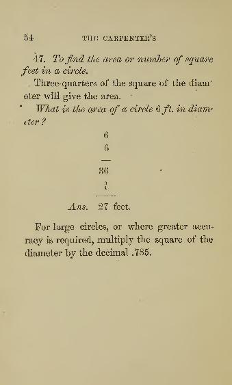
47. To find the area or number of square
feet in a cirele.
Three-quarters of the square of the diam'
eter will give the area.
What is the area of a circle &fL in diam'
eter ?
6
6
36
34
Ans, 27 feet.
For large circles, or where greater accu-
racy is required, multiply the square of the
diameter by the decimal .785.

\
HAKD-BOOK. 55
48. Capacity of wells and cisterns.
One foot in depth of a cistern :
3 feet in diameter contains 55^ gallons.
3i u u a /jrg a
4 " " " 98 "
^ u u u 1241 "
5 " " 153i"
51 feet in diameter contains 185^ "
6 " 220| "
7 " " 300i"
8 " " " 392i"
9 " " 497 "
10 " " " 6131 a
A gallon is required by law to contain
eight pounds of pure water.

56 THE CARPEl^TEK'S
49. Weights of vdvious materials :
Lbs. in acubic foot.
Cast-iron - - - - - 460
Cast-lead - - - - Y09
Gold - - 1,210
Platina - - - - 1,345
Steel - - 488
Pewter - - 453
Brass - 506
Copper - - 549
Granite -. - - - 166
Marble - - 170
Blue stone - 160
Pnmice-stone - 56
Glass - 160
Chalk - - - 150
Brick - - 103
Brickwork laid - - - 95
Clean sand - 100
Beech-wood - - 40
Ash . 45
Birch - - - - - 45
Cedar - - 28

HAITD-BOOK. 57Lbs. in acubic foot.
Hickory 52
Ebony 83
Lignuin-vitae - - - - 83
Pine, yellow - - - . . 38
Cork ...... 15
Pine, white - - - - 25
Bircli charcoal - - - - 34
Pine "... - 18
Beeswax 60
"Water - - - - 62^


i
i
i