Embed Size (px)
Citation preview
Software Engineering InstituteCarnegie Mellon UniversityPittsburgh, PA 15213-3890
Sponsored by the U.S. Department of Defense© 1998 by Carnegie Mellon University
Carnegie Mellon UniversitySoftware Engineering Institute
Chapter 3 - page 1Version 1.0
Software Architecture inPracticeChapter 3: A-7E Avionics System - ACase Study in Architectural Structures
© 1998 by Carnegie Mellon University
Carnegie Mellon UniversitySoftware Engineering Institute
Version 1.0 Chapter 3 - page 2
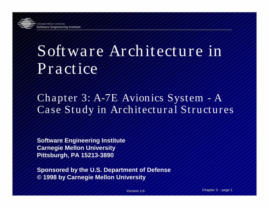
Lecture Objectives
This lecture will enable students to• see examples of architectural structures used
in a real system• understand how these structures were
engineered to achieve architectural qualityattributes
• understand how information hiding came to beaccepted as an important architectural principle

© 1998 by Carnegie Mellon University
Carnegie Mellon UniversitySoftware Engineering Institute
Version 1.0 Chapter 3 - page 3
A-7E Corsair II AircraftU. S. carrier-based, light attack aircraft
Used from the 1960s through the 1980s
Small computer on board for navigation, weaponsdelivery

© 1998 by Carnegie Mellon University
Carnegie Mellon UniversitySoftware Engineering Institute
Version 1.0 Chapter 3 - page 4
Background of Old System
Fit into 32K of memory
Written in Assembler
Had to be optimized for efficiency
Brittle, hard to modify

© 1998 by Carnegie Mellon University
Carnegie Mellon UniversitySoftware Engineering Institute
Version 1.0 Chapter 3 - page 5
ABC for the A-7E II
Architect’s influencesCustomer and end userNaval aviators
Developing organizationUS Naval Research Lab
Technical environmentInformation hidingCooperating sequential processesArchitect’s experienceAcademicAccess to other systems
Requirements(Qualities)ModifiabilityPerformance
ArchitectureModule structureUses structureProcess structure
SystemA-7E avionics
Architect(s)
© 1998 by Carnegie Mellon University
Carnegie Mellon UniversitySoftware Engineering Institute
Version 1.0 Chapter 3 - page 6
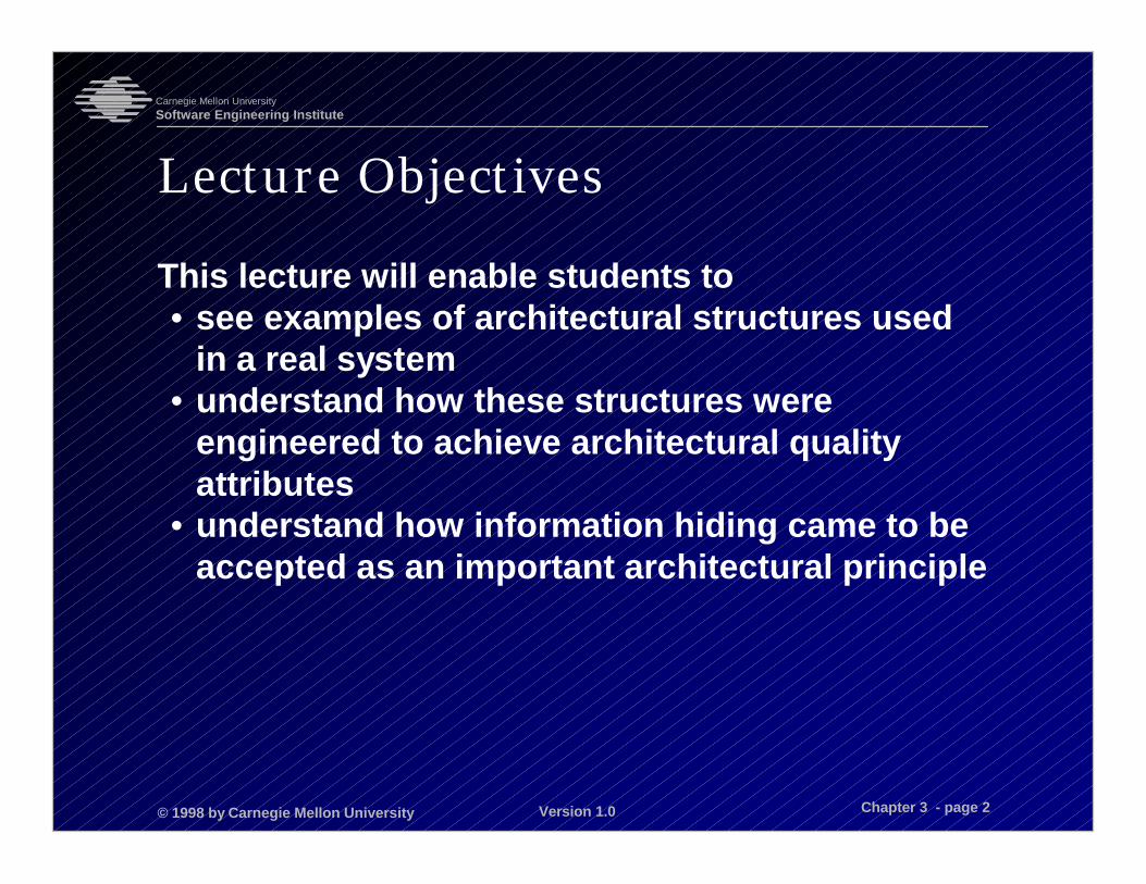
Behavioral Requirements -1
Program
Data in from• sensors• pilot controls
Data out to• cockpit display• weapon release hardware

© 1998 by Carnegie Mellon University
Carnegie Mellon UniversitySoftware Engineering Institute
Version 1.0 Chapter 3 - page 7
Behavioral Requirements -2
Read data from sensors such as• air probe• aimable forward-looking radar• Doppler radar• inertial measurement set• type of weapon loaded on each wing station• dozens of switches in the cockpit

© 1998 by Carnegie Mellon University
Carnegie Mellon UniversitySoftware Engineering Institute
Version 1.0 Chapter 3 - page 8
Behavioral Requirements -3
Release wing-mounted weapons.
Manage cockpit displays such as• heads-up display (HUD)• moving map display• keypad and alpha-numeric display• warning lights• cockpit dials

© 1998 by Carnegie Mellon University
Carnegie Mellon UniversitySoftware Engineering Institute
Version 1.0 Chapter 3 - page 9
Behavioral Requirements -4
The pilot could communicate the location of aground target to the software by• moving a cursor on the HUD over it, and
pressing a “designate” button• moving a cursor on the map over it, and
pressing a “designate” button• manually aiming the forward-looking radar to
the point and pressing the “designate” button• entering its latitude/longitude via the keypad
The software then computed the time to target,heading, and other values.
© 1998 by Carnegie Mellon University
Carnegie Mellon UniversitySoftware Engineering Institute
Version 1.0 Chapter 3 - page 10
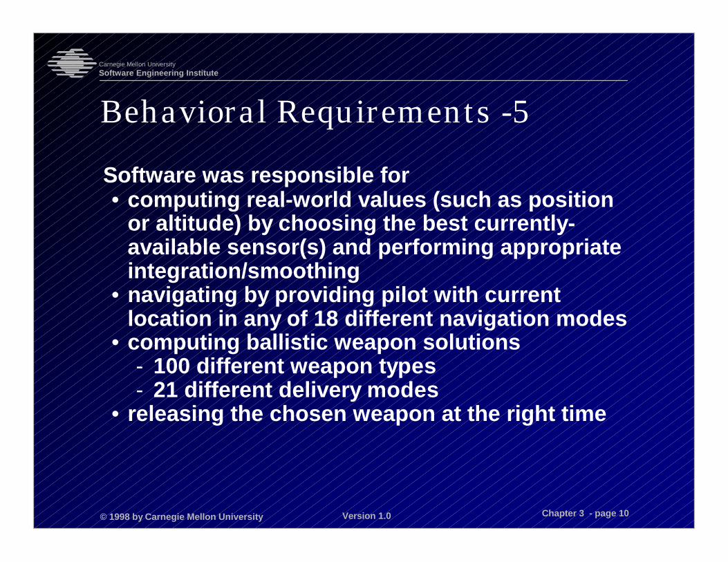
Behavioral Requirements -5
Software was responsible for• computing real-world values (such as position
or altitude) by choosing the best currently-available sensor(s) and performing appropriateintegration/smoothing
• navigating by providing pilot with currentlocation in any of 18 different navigation modes
• computing ballistic weapon solutions- 100 different weapon types- 21 different delivery modes
• releasing the chosen weapon at the right time
© 1998 by Carnegie Mellon University
Carnegie Mellon UniversitySoftware Engineering Institute
Version 1.0 Chapter 3 - page 11
Quality Requirements
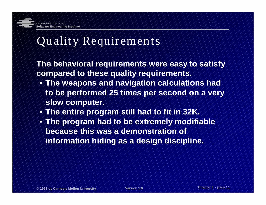
The behavioral requirements were easy to satisfycompared to these quality requirements.• The weapons and navigation calculations had
to be performed 25 times per second on a veryslow computer.
• The entire program still had to fit in 32K.• The program had to be extremely modifiable
because this was a demonstration ofinformation hiding as a design discipline.

© 1998 by Carnegie Mellon University
Carnegie Mellon UniversitySoftware Engineering Institute
Version 1.0 Chapter 3 - page 12
Architectural Approach
Concentrated on three architectural structures• module structure
- to achieve modifiability- to achieve flexibility of producing subsets- to allocate expertise
• uses structure: to ease production of subsets• process structure: to achieve portability,
performance tuning

© 1998 by Carnegie Mellon University
Carnegie Mellon UniversitySoftware Engineering Institute
Version 1.0 Chapter 3 - page 13
A-7E Architectural Structures
Module structure
Uses structure
Process structure
© 1998 by Carnegie Mellon University
Carnegie Mellon UniversitySoftware Engineering Institute
Version 1.0 Chapter 3 - page 14
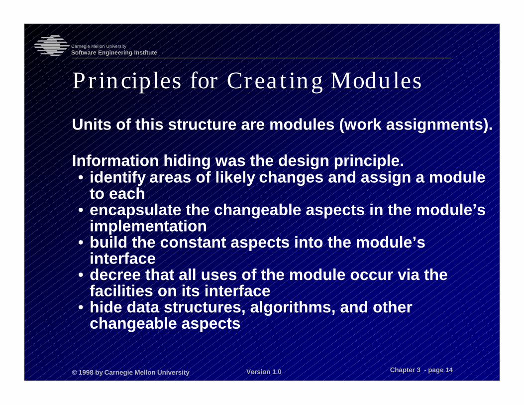
Principles for Creating ModulesUnits of this structure are modules (work assignments).
Information hiding was the design principle.• identify areas of likely changes and assign a module
to each• encapsulate the changeable aspects in the module’s
implementation• build the constant aspects into the module’s
interface• decree that all uses of the module occur via the
facilities on its interface• hide data structures, algorithms, and other
changeable aspects

© 1998 by Carnegie Mellon University
Carnegie Mellon UniversitySoftware Engineering Institute
Version 1.0 Chapter 3 - page 15
Classifying Changes
Three classes of change• hardware
- new devices- new computer
• required behavior- new functions- new rules of computing cockpit displays- new modes
• software decisions- new ways to schedule processes- new ways to represent data types- new ways to keep data current
© 1998 by Carnegie Mellon University
Carnegie Mellon UniversitySoftware Engineering Institute
Version 1.0 Chapter 3 - page 16
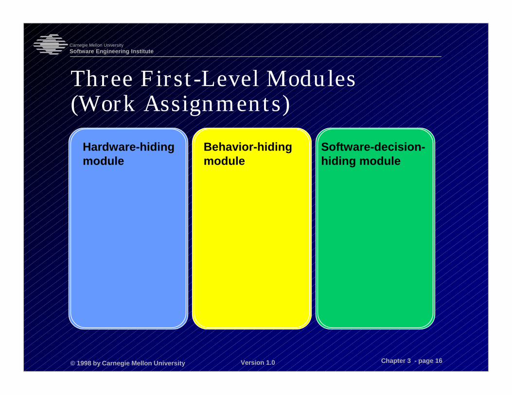
Three First-Level Modules(Work Assignments)
Hardware-hiding module
Behavior-hiding module
Software-decision-hiding module
© 1998 by Carnegie Mellon University
Carnegie Mellon UniversitySoftware Engineering Institute
Version 1.0 Chapter 3 - page 17
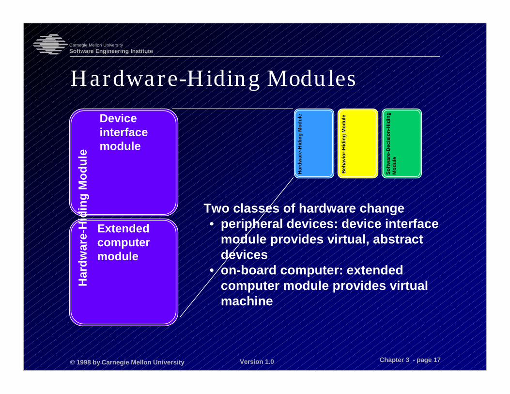
Hardware-Hiding Modules
Two classes of hardware change• peripheral devices: device interface
module provides virtual, abstractdevices
• on-board computer: extendedcomputer module provides virtualmachine
Har
dwar
e-H
idin
g M
odul
e
Deviceinterfacemodule
Extendedcomputermodule
Sof
twar
e-D
ecis
ion-
Hid
ing
Mod
ule
Beh
avio
r-H
idin
g M
odul
e
Har
dwar
e-H
idin
g M
odul
e
© 1998 by Carnegie Mellon University
Carnegie Mellon UniversitySoftware Engineering Institute
Version 1.0 Chapter 3 - page 18
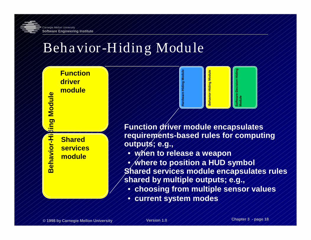
Behavior-Hiding Module
Function driver module encapsulatesrequirements-based rules for computingoutputs; e.g.,• when to release a weapon• where to position a HUD symbol
Shared services module encapsulates rulesshared by multiple outputs; e.g.,• choosing from multiple sensor values• current system modes
Beh
avio
r-H
idin
g M
odul
e
Functiondrivermodule
Sharedservicesmodule
Sof
twar
e-D
ecis
ion-
Hid
ing
Mod
ule
Beh
avio
r-H
idin
g M
odul
e
Har
dwar
e-H
idin
g M
odul
e
© 1998 by Carnegie Mellon University
Carnegie Mellon UniversitySoftware Engineering Institute
Version 1.0 Chapter 3 - page 19
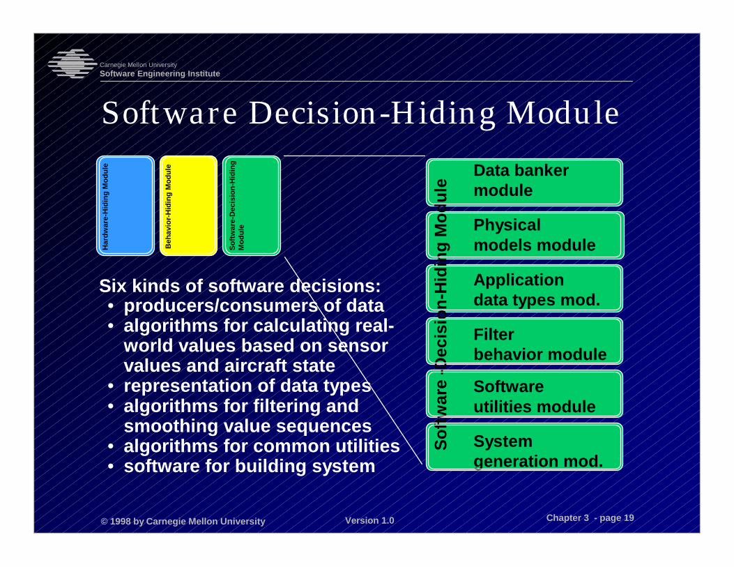
Software Decision-Hiding Module
Six kinds of software decisions:• producers/consumers of data• algorithms for calculating real-
world values based on sensorvalues and aircraft state
• representation of data types• algorithms for filtering and
smoothing value sequences• algorithms for common utilities• software for building system
Data bankermodule
Physicalmodels module
Applicationdata types mod.
Filterbehavior module
Softwareutilities module
Systemgeneration mod.
Sof
twar
e -D
ecis
ion-
Hid
ing
Mod
ule
Sof
twar
e-D
ecis
ion-
Hid
ing
Mod
ule
Beh
avio
r-H
idin
g M
odul
e
Har
dwar
e-H
idin
g M
odul
e
© 1998 by Carnegie Mellon University
Carnegie Mellon UniversitySoftware Engineering Institute
Version 1.0 Chapter 3 - page 20
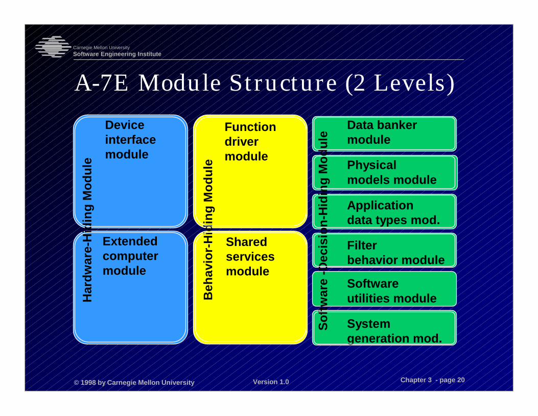
A-7E Module Structure (2 Levels)H
ardw
are-
Hid
ing
Mod
ule
Deviceinterfacemodule
Extendedcomputermodule
Beh
avio
r-H
idin
g M
odul
e
Functiondrivermodule
Sharedservicesmodule
Data bankermodule
Physicalmodels module
Applicationdata types mod.
Filterbehavior module
Softwareutilities module
Systemgeneration mod.
Sof
twar
e -D
ecis
ion-
Hid
ing
Mod
ule
© 1998 by Carnegie Mellon University
Carnegie Mellon UniversitySoftware Engineering Institute
Version 1.0 Chapter 3 - page 21
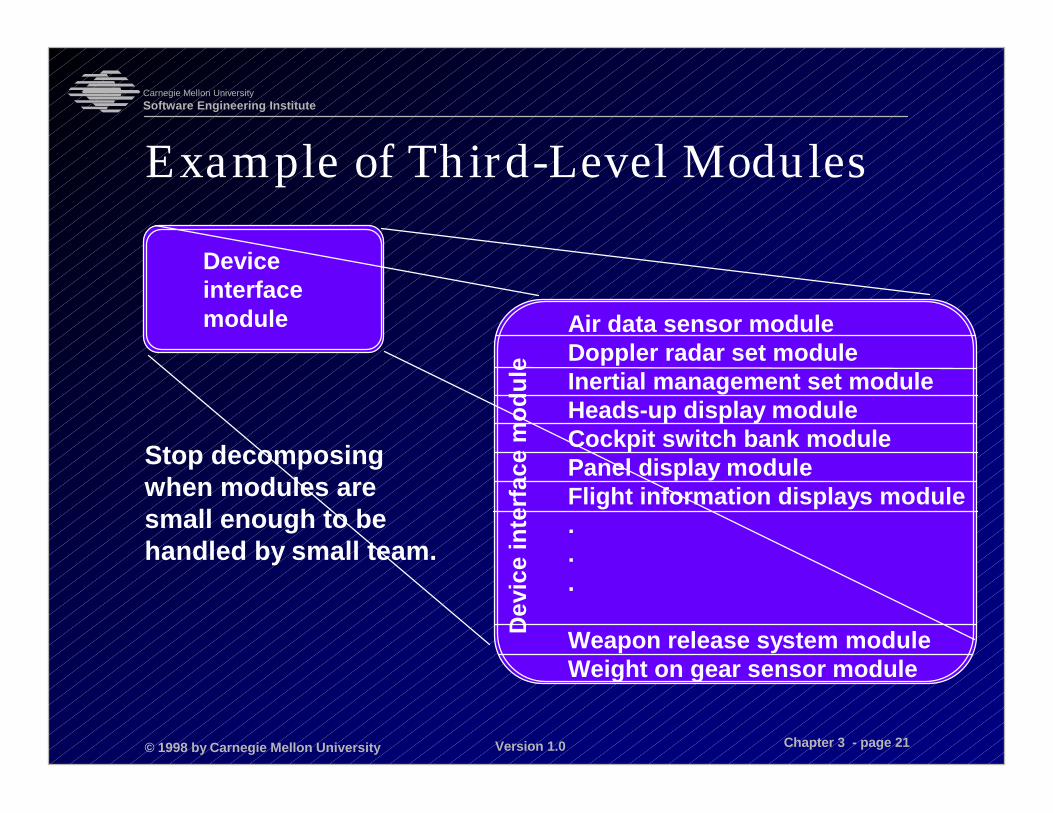
Example of Third-Level Modules
Stop decomposingwhen modules aresmall enough to behandled by small team.
Dev
ice
inte
rfac
e m
odul
e
Air data sensor moduleDoppler radar set moduleInertial management set moduleHeads-up display moduleCockpit switch bank modulePanel display moduleFlight information displays module...
Weapon release system moduleWeight on gear sensor module
Deviceinterfacemodule

© 1998 by Carnegie Mellon University
Carnegie Mellon UniversitySoftware Engineering Institute
Version 1.0 Chapter 3 - page 22
Module Structure As Team Structure
Basis for team assignment: One team was formedfor each second-level module.
Basis for document organization: The bulk of thedocument corresponded to modules, althoughother structures were documented separately.
© 1998 by Carnegie Mellon University
Carnegie Mellon UniversitySoftware Engineering Institute
Version 1.0 Chapter 3 - page 23
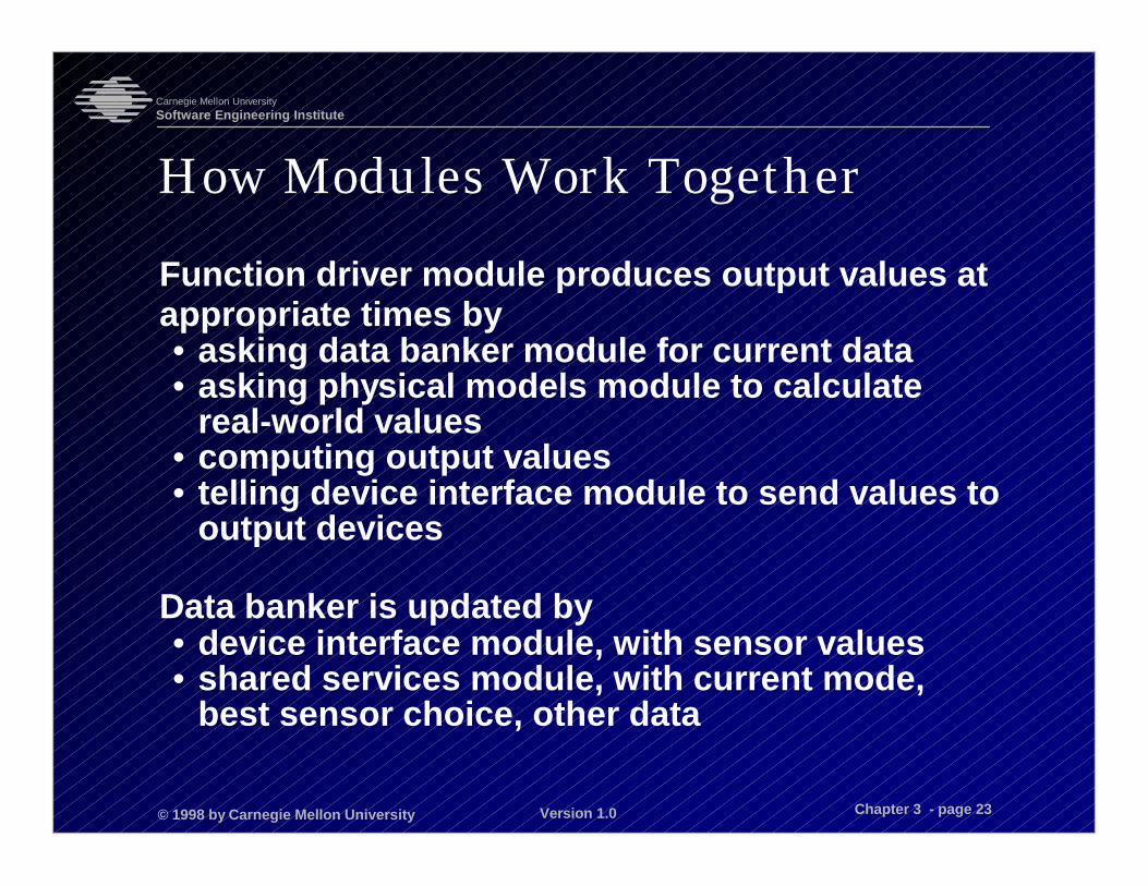
How Modules Work Together
Function driver module produces output values atappropriate times by• asking data banker module for current data• asking physical models module to calculate
real-world values• computing output values• telling device interface module to send values to
output devices
Data banker is updated by• device interface module, with sensor values• shared services module, with current mode,
best sensor choice, other data
© 1998 by Carnegie Mellon University
Carnegie Mellon UniversitySoftware Engineering Institute
Version 1.0 Chapter 3 - page 24
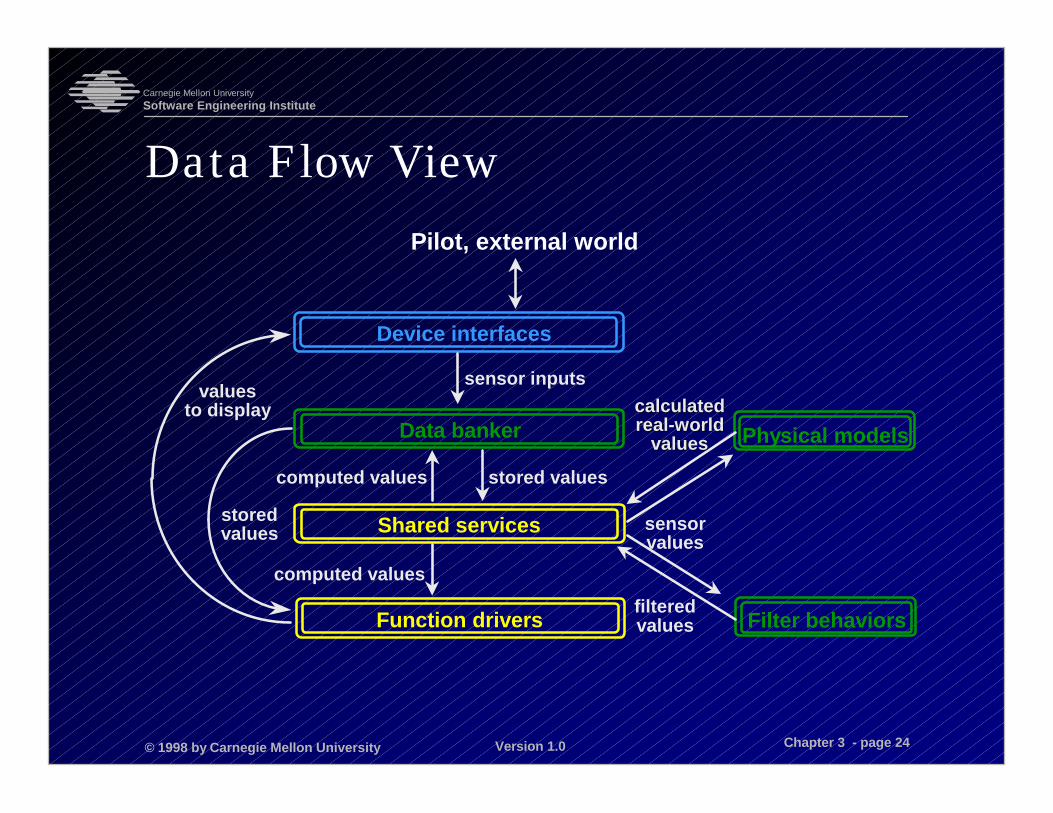
Data Flow View
Device interfaces
Data banker
Shared services
Function drivers Filter behaviors
Physical models
sensor inputs
computed values stored values
computed values
storedvalues
valuesto display
filteredvalues
sensorvalues
calculatedcalculatedreal-worldreal-world
valuesvalues
Pilot, external world

© 1998 by Carnegie Mellon University
Carnegie Mellon UniversitySoftware Engineering Institute
Version 1.0 Chapter 3 - page 25
A-7E Architectural Structures
Module structure
Uses structure
Process structure

© 1998 by Carnegie Mellon University
Carnegie Mellon UniversitySoftware Engineering Institute
Version 1.0 Chapter 3 - page 26
Definition of Uses RelationUnits of this structure are programs.
Program A uses program B if a correctlyfunctioning B must be present for A to meet itsrequirements.
Similar to calls, but not quite the same• A might call B, but not use it (e.g., if B is an
exception handler, A’s correctness does notdepend on anything that B computes).
• A might use B even if it doesn’t call it (e.g.,assumption that B has left some computedvalue in an accessible place).
© 1998 by Carnegie Mellon University
Carnegie Mellon UniversitySoftware Engineering Institute
Version 1.0 Chapter 3 - page 27
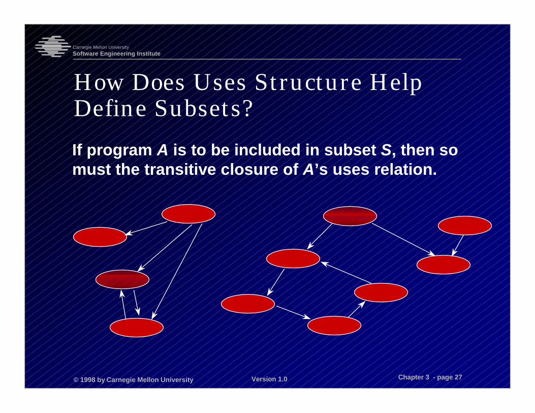
How Does Uses Structure HelpDefine Subsets?If program A is to be included in subset S, then somust the transitive closure of A’s uses relation.
© 1998 by Carnegie Mellon University
Carnegie Mellon UniversitySoftware Engineering Institute
Version 1.0 Chapter 3 - page 28
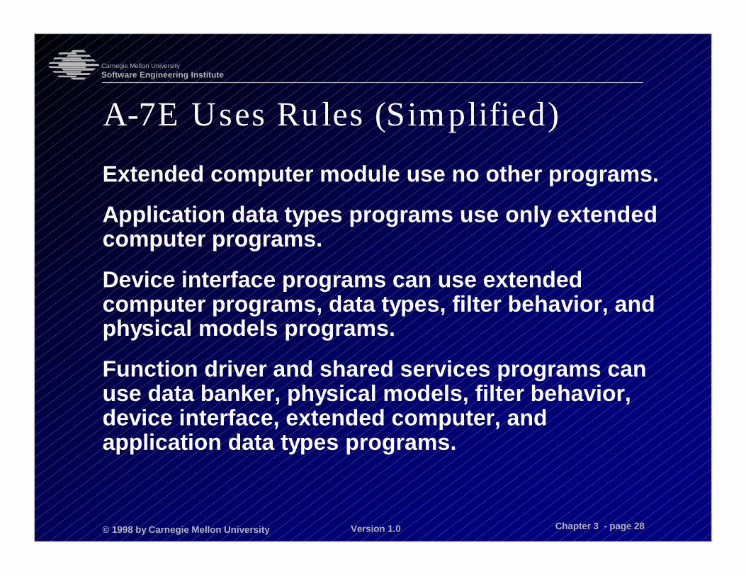
A-7E Uses Rules (Simplified)Extended computer module use no other programs.
Application data types programs use only extendedcomputer programs.
Device interface programs can use extendedcomputer programs, data types, filter behavior, andphysical models programs.
Function driver and shared services programs canuse data banker, physical models, filter behavior,device interface, extended computer, andapplication data types programs.
© 1998 by Carnegie Mellon University
Carnegie Mellon UniversitySoftware Engineering Institute
Version 1.0 Chapter 3 - page 29
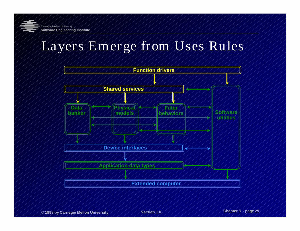
Layers Emerge from Uses RulesFunction drivers
Extended computer
Application data types
Device interfaces
Databanker
Physicalmodels
Filterbehaviors
Shared services
Softwareutilities

© 1998 by Carnegie Mellon University
Carnegie Mellon UniversitySoftware Engineering Institute
Version 1.0 Chapter 3 - page 30
Layering
Layering is a well-known style that can provideportability across computing platforms and quickreimplementation of applications.
Layering is not clean. There are often “short-cuts”for performance or other reasons.
The uses structure suggests a layering, but theyare not interchangeable. The layered structureallows only a very restrictive definition of subsets.
© 1998 by Carnegie Mellon University
Carnegie Mellon UniversitySoftware Engineering Institute
Version 1.0 Chapter 3 - page 31
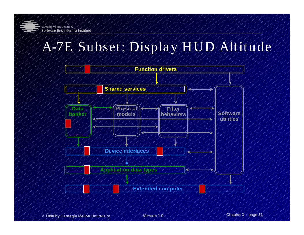
A-7E Subset: Display HUD AltitudeFunction drivers
Extended computer
Application data types
Device interfaces
Databanker
Physicalmodels
Filterbehaviors
Shared services
Softwareutilities

© 1998 by Carnegie Mellon University
Carnegie Mellon UniversitySoftware Engineering Institute
Version 1.0 Chapter 3 - page 32
A-7E Architectural Structures
Module structure
Uses structure
Process structure
© 1998 by Carnegie Mellon University
Carnegie Mellon UniversitySoftware Engineering Institute
Version 1.0 Chapter 3 - page 33
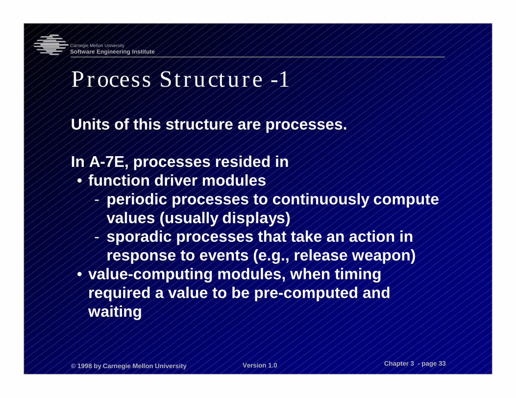
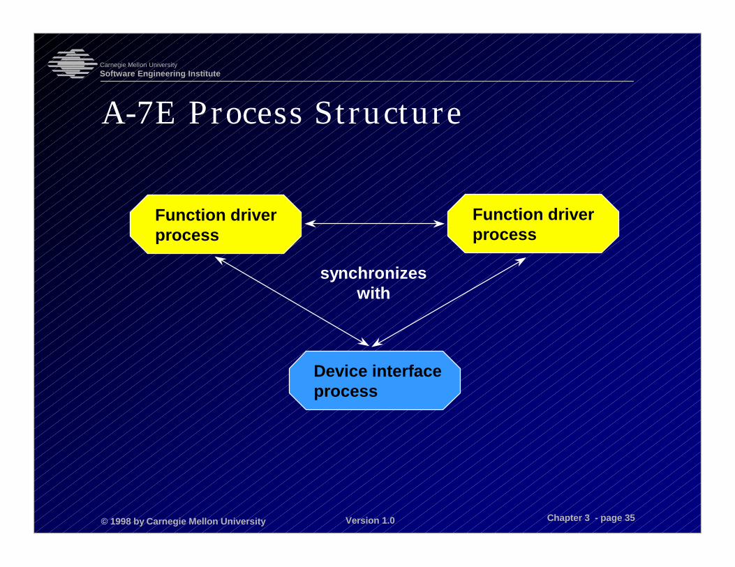
Process Structure -1
Units of this structure are processes.
In A-7E, processes resided in• function driver modules
- periodic processes to continuously computevalues (usually displays)
- sporadic processes that take an action inresponse to events (e.g., release weapon)
• value-computing modules, when timingrequired a value to be pre-computed andwaiting
© 1998 by Carnegie Mellon University
Carnegie Mellon UniversitySoftware Engineering Institute
Version 1.0 Chapter 3 - page 34
Process Structure -2
The computer had only one processor.
Off-line scheduling was used to build a schedulewithout the expense of a runtime executive.
The primary relation was “synchronizes with” or“excludes” (in the case of using sharedresources). The scheduler used these relations togenerate a schedule.
Processes could be merged by the scheduler forperformance gains.
© 1998 by Carnegie Mellon University
Carnegie Mellon UniversitySoftware Engineering Institute
Version 1.0 Chapter 3 - page 35
A-7E Process Structure
synchronizeswith
Function driverprocess
Function driverprocess
Device interfaceprocess
© 1998 by Carnegie Mellon University
Carnegie Mellon UniversitySoftware Engineering Institute
Version 1.0 Chapter 3 - page 36
Case Study Summary -1
Three distinct structures (uses, module, andprocess) were used to design this system. Thosestructures (and others) are its architecture.
Each structure was engineered to achieveparticular quality attributes. Structures were notallowed simply to happen on their own.
Information hiding was new and untested at thetime of the A-7. It was shown to be a viabledesign strategy for building hard-real-timeembedded computer software.
© 1998 by Carnegie Mellon University
Carnegie Mellon UniversitySoftware Engineering Institute
Version 1.0 Chapter 3 - page 37
Case Study Summary -2
Information hiding has come to be accepted as astandard structuring technique for softwarearchitectures.
The requirement of fitting the program into 32Kwas not met.
© 1998 by Carnegie Mellon University
Carnegie Mellon UniversitySoftware Engineering Institute
Version 1.0 Chapter 3 - page 38
Discussion Questions -1
1. Suppose a version of the A-7E software were tobe developed for installation on a flight trainerversion of the aircraft. This aircraft would carryno weapons, but it would teach pilots how tonavigate using the on-board avionics. Whatstructures of the architecture would have tochange, and why?

© 1998 by Carnegie Mellon University
Carnegie Mellon UniversitySoftware Engineering Institute
Version 1.0 Chapter 3 - page 39
Discussion Questions -22. Later in the course, we will discuss using
architecture as a basis for incrementaldevelopment: starting small and growing thesystems, but having a working subset at all times.Propose the smallest subset of the A-7E softwarethat you can think of that still does something(correctly, in accordance with requirements) that isobservable by the pilot. (A good candidate isdisplaying a value such as current heading on somecockpit display.) Which modules would you needand which could you do without? Now proposethree incremental additions to that subset andspecify the development plan (i.e., which modulesyou need) for those.
© 1998 by Carnegie Mellon University
Carnegie Mellon UniversitySoftware Engineering Institute
Version 1.0 Chapter 3 - page 40
Discussion Questions -3
3. Suppose that monitors were added to ensurethat correct values were being stored in thedata banker and computed by the functiondrivers. If the monitors detected a disparitybetween the stored or computed values, andwhat they computed as the correct values, theywould signal an error. Show how each of theA-7E’s architectural structures would changeto accommodate this design. If you addmodules, state the information-hiding criteriafor placing it in the module hierarchy.