Embed Size (px)
DESCRIPTION
Energy costs are becoming a significant expense in most processes. With increased energy unit costs, decreased generating capacity, and the environmental concerns with the burning of fossil fuels, it is important that companies reduce their electrical consumption.Carlo Gavazzi offers a broad range of energy meters and power quality meters and transducers for monitoring energy consumption as well as problems with power quality.In addition, with the move towards renewable energy, monitoring of photo-voltaic strings is becoming important in order to maximize generating capacity. Our EOS Array system allows you to monitor the current, voltage, power, temperature, and irradiation levels of your entire solar installation.In order to interface with external systems, output options include :RelaysAnalogueRS232RS485Ethernet (Modbus and BacNet)In addition to our broad range of energy meters and power quality meters, Carlo Gavazzi also offers a number of software products for monitoring of a network of meters and transducers. This allows at-a-glance viewing of your complete power system.
Citation preview

A Lifetime of Commitment to AutomationA Lifetime of Commitment to Automation
EGYPTIAN INDUSTRIAL SOLUTIONS
SMART SOLUTIONS
Block 37- Section 14063 - 6th Zone - Oboor City - Qalyoubia –Egypt , Zip Code :11828
Tel:+(202)46105972- Fax: +(202)46105972 – Mobile: +20101809409
Email :[email protected]
16Copyright 2010 EGYPTIAN INDUSTRIAL SOLUTIONS Co. All Rights Reserved.


What is and Why use theEnergy Management ComponentsGreen levies, tighter operating margins and profits area few economic drivers forcing operators to use moreintelligent power management strategies.Real-time measurements of electrical parameters, such asvoltage variations or distortions, can be transmitted vianetworks to operators, warning of breaches in thresholdlimits. And, the power quality information improveson-site efficiency and eases negotiation with utilitycompanies and energy authorities.For starters, several utility meters or power analysersshould be located at the service entrance and at strategicpoints throughout the site. Data can be transmitted to ahost PC over a serial link. Meanwhile, an energy mana-gement software improves real-time data from severalnetworked nodes so to work out a power profile.Large commercial or industrial electricity consumershave to deal with fixed energy charges related to thepower demand of one or more sites as well as the chargeper unit of energy consumed. If the business exceeds
the agreed power demand or “installed power” then itis forced to pay extra costs. To matters worse, utilitiescan also impose higher installed power tariffs that canoften represent up to 60% of a commercial consumer’stotal utility charge. So clearly, a small mistake thatleads to a brief excess power demand can cost manythousands of euro.Carlo Gavazzi supplies EM systems that provide infor-mation so that operators can identify consumptiontrends and take corrective actions. Analysing the powerprofile operators can also aggregate loads and sonegotiate more favourable terms with the utility com-pany. Real time power consumption monitoring alsoallows a site manager to anticipate overloads conditionsthat would, for example, trip a circuit breaker.Alarm thresholds can be set to warn managers if presetlimits are reached, and armed with the adequatesystem loading and status information having time toorganise remedial actions.
2
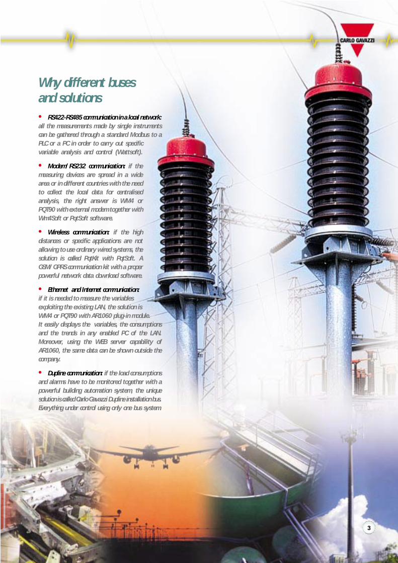
Why different busesand solutions• RS422-RS485 communication in a local network:all the measurements made by single instrumentscan be gathered through a standard Modbus to aPLC or a PC in order to carry out specificvariable analysis and control (Wattsoft).
• Modem/RS232 communication: if themeasuring devices are spread in a widearea or in different countries with the needto collect the local data for centralisedanalysis, the right answer is WM4 orPQT90 with external modem together withWm4Soft or PqtSoft software.
• Wireless communication: if the highdistances or specific applications are notallowing to use ordinary wired systems, thesolution is called PqtKit with PqtSoft. AGSM/GPRS communication kit with a properpowerful network data download software.
• Ethernet and Internet communication:if it is needed to measure the variablesexploiting the existing LAN, the solution isWM4 or PQT90 with AR1060 plug-in module.It easily displays the variables, the consumptionsand the trends in any enabled PC of the LAN.Moreover, using the WEB server capability ofAR1060, the same data can be shown outside thecompany.
• Dupline communication: if the load consumptionsand alarms have to be monitored together with apowerful building automation system, the uniquesolution is called Carlo Gavazzi Dupline installation bus.Everything under control using only one bus system.
3

When an idea becomes a great idea …The introduction of the Climate Change Levy is affect-ing consumers of energy in one way or another. Thebasic outcome is that users who are inefficient in theiruse of energy will pay more than efficient users. Thereare several ways to avoid or reduce the extra costs ofthe CCL but most of them involve some major invest-ments in plants or new technologies such as CHP, windpower or other renewable energy sources. The easiestway to offset these extra costs is to control your con-sumption of energy.
Energy Management and Dupline Field Bus . . .making energy metering easy in very noisy plants
The fundamental questions you have to askin order to find a solution to save energyand money• How much energy is consumed?• Is there any energy waste?
… and the answers?• Find an easy way to measure it• For sure, there are loads that are running even
if it is not necessary. For instance, lights andextractor fans when the building is empty.Therefore a smart system to turn the loads ONand OFF is needed.
The unlimited efficient solution possibilitiesprovided by the Dupline Field Bus• Light control, switching ON/OFF and dimming lights;• Temperature control, detecting signals from infrared
remote controls or PIR sensors and acting on heatingelements and/or valves;
• Ventilation control, measure of room and outdoortemperature;
• Monitoring of doors, locks and windows;• Monitoring of fire alarms from smoke detectors;• Water leakage detection using proper sensors;• And many others …
Main application advantages• Free topology for a fast, flexible and easy to build
step-by-step installation; the system can be easilyadapted to new unexpected requirements.
• User friendly: easy to code addresses and test, easilyaccessible data from a PC/PLC.
• High electrical noise immunity, no shielded cablesare needed therefore existing cable/conduit/pipecan be exploited.
• Data communication up to 10 km, no signal repeatersare needed.
• Integration of the metering system with the Duplinedoor-light-intrusion-remote controls and load switching.
• Cost-effective solution when compared with theordinary systems.
Du line®
Fieldbus Installationbus
4

Energy ManagementThe other Fieldbuscompatible instruments:DIN-rail mounting:EM1-WM1-SPT-PQTFlush mounting:WM2-WM3-WM24-WM4.
The main Bus devicesIndividual counterG 4420 74014 inputs for: 4*kWh meters;2*kWh + 2*kvarh meters. Reset feature.Data retention in case of power failure.
Master channel generatorG 3890 0014 G 3800 0015 Power supply:115V, 230VAC or 10 to 30VDC
The data acquisition systemThe Dupline DDE Server toacquire the information ofthe Energy meters throughthe Dupline field Bus system.
Displays and accessoriesLCD text display, LED display,coding units, repeater.
Bus-Powered SensorsInductive-magnetic proximity switches,PIR-sensors, temperature sensors.
Analogue I/O Modules1or 4*20mA/10VDC inputs,1or 4*20mA/10VDC outputs.
Digital I/O Modules1 to 8 contact inputs, 1 to 8outputs, combined I/O modules.
Gateways and InterfacesProfibus-DP, Devicenet, LonWork,Interbus-S, ModBus.PLC direct interfaces, Modem.
5

The Energy Management components for . . .
Commercial Buildings: Shopping Centres, Resorts,Supermarkets, Restaurants
Services and Infrastructures: Schools, Hospitals,Stadiums
In many commercial buildings as a matter of fact the need tocontrol and measure the energy consumption by single user isbecoming more and more important because of the need tosave money or issue the energy bill when needed.Since the criterion is “the higher the energy consumption thelower the price” instead of having a supply contract for everyshop/owner with a low consumption (higher energy cost),there is only one contract with high consumption (lower energycost) whose sub-metering can be easily carried out using ourenergy meters and power analysers.Moreover the intelligent installationsbus Dupline can be commonto our energy metering system and our Building Automationsystem. It allows, using proper Dupline sensors (temperature,light) and I/O modules, to manage the lighting system as wellas the heating and air conditioning system so to achievefurther energy cost savings.In the services and infrastructures, in addition to the buildingautomation system already mentioned above, there is alsothe need to have a full electrical parameters control. In thoseplaces the reliability of power supply and therefore the safetyconditions are of vital importance. Dupline can be exploitedto gather and manage the alarms coming from our poweranalysers so to notify abnormal conditions in order to let themaintenance personnel act in a due time.
Lighting Heating Conditioning Alarms Billing
Commercial Buildings Services and Infrastructures
6

Production Facilities: Cost Allocation Light and Medium Industry: Loads Control
Since the cost pressure on pro-duction is becoming higherand higher, the energy con-sumption measured by type ofproduction allows to allocateand control the costs in aproper and more accurat way.Our Building Automationsystem based on Dupline busand relevant modules in com-bination with our energy mete-ring system allows to managethe lighting system as well asother loads so to achieve furtherenergy cost savings.
In the past just simple measu-ring systems like current-voltage-power and power factor wereavailable to keep the mainsunder control. More complexsolutions were available aswell but in many cases reque-sted higher investments.Nowadays more and moresophisticated machines andloads are used in the productionfacilities like computers, swit-ching-mode power suppliesand drives thus increasingsignificantly the complexity ofloads and of problems. CarloGavazzi is capable to providedifferent levels of solution:• WM12, a powerfuland compact unitreplacing the ordinaryset of three ammeters,one voltmeter and onerotary-switch;• a more advancedsystem which includes in addition to the power analysers alsoa powerful supervision software with the aim to build-up aninstallation and load history so to prevent with a plannedmaintenance scheme load failures and production stops.
Light and Medium Industry
Lighting Heating Ventilation Cost
Production Facility
7
The Energy Management components for . . .
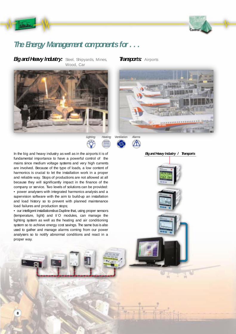
Transports: AirportsBig and Heavy Industry: Steel, Shipyards, Mines,Wood, Car
In the big and heavy industry as well as in the airports it is offundamental importance to have a powerful control of themains since medium voltage systems and very high currentsare involved. Because of the type of loads, a low content ofharmonics is crucial to let the installation work in a properand reliable way. Stops of productions are not allowed at allbecause they will significantly impact in the finance of thecompany or service. Two levels of solutions can be provided:• power analysers with integrated harmonics analysis and asupervision software with the aim to build-up an installationand load history so to prevent with planned maintenanceload failures and production stops;• our intelligent installationsbus Dupline that, using proper sensors(temperature, light) and I/O modules, can manage thelighting system as well as the heating and air conditioningsystem so to achieve energy cost savings. The same bus is alsoused to gather and manage alarms coming from our poweranalysers so to notify abnormal conditions and react in aproper way.
Lighting Heating Ventilation Alarms
Big and Heavy Industry / Transports
8

Telecom: TelecommunicationsWater: Potable Water Plants, Water Distribution Plants
A water treatment and distri-bution system is, because ofdimensions of plants, distancesamong the various pumpingstations and parameters to beinvolved, very hard to manage.The Carlo Gavazzi Duplineinstallationsbus with its up to10 km transmission distance,its free topology and thevariety of analogue and digi-tal I/O modules is capable togather all the level, flow andalarm signals and the pumpsstart and stop in order tomanage the whole system in areliable and cost effective way.Last but not least, the monito-ring of mains and working ofpumps with local power analy-sers and fully integrated datalogging system is crucial togrant a continuous load con-trol that with GSM modem andSMS transmission capability,alerts service staff on theirmobile phones as soon as anabnormal condition occurs.
Everybody knows how impor-tant the mobile telecommunica-tion is nowadays and will beeven more in the future.The relevant antennas areinstalled in the field and haveto grant the communicationwithout problems.Since field telecommunicationsystems are not attended at all,it is needed to provide to themobile phone company infor-mation related to the voltage,current, power and in somecases also energy consumptions.Carlo Gavazzi is able, withdifferent level of instrumentcomplexity, to provide therequested electrical parame-ters using, according to theinstallation needs, compact ormodular power analysers.
Pump Level Flow Alarms
Water treatment and Distribution Telecom
9

Energy meter
Power Analyzer
Multi Function Meter
Power Quality Analyzer
Universal Utility Meter
Transducer
Power Quality Transducer
Modular
Graphic Display
Digital Inputs
Pulse outputs
Analogue Outputs
Alarm Outputs
Serial Communication
Internet-Ethernet Communication
GSM/SMS Management
Energy
Gas and H2O Metering
Instantaneous Variables
EM1 DINPage 16
EM2 DINPage 16
EM2 96Page 16
EM3 DINPage 17
EM4 DINPage 18
WM1 DINPage 19
WM12 DIN/96Page 20
10

WM14 DIN/96Page 21
WM2 DINPage 19
WM2 96Page 19
WM22 DINPage 22
WM23 96Page 23
WM24 96Page 24
WM3 96Page 26/27
WM4 96Page 28/29
SPT 90Page 25
PQT 90Page 30/31
CVT DINPage 33
11

The Product Advantages
EM1 DIN• Direct connection up to 22.5 A, no CT is needed• TRMS measurement• Self power supply, easy connection
EM2 DIN, EM2 DIN• Large display• Compact housing, only 107mm wide• User friendly
EM3 DIN, EM4 DIN, WM22 DIN• Plug and play modules• Maximum in-field flexibility• Possibility to add any outputs only when really needed
by the application
WM1 DIN• Compact Power Analyzer
WM12 DIN, WM12 96, WM14 DIN, WM14 96• Replacement of ordinary “DPMs and analogue
instrumentation combined by rotary switches”• Status of system power supply and neutral current available
at a glance• 96x96 version with only 46 mm housing behind panel,
suitable for all switch and control gears
EM2 96, WM2 96,• Plug and play modules• Maximum in-field flexibility• Possibility to add any outputs only when really needed
by the application
WM23 96, WM3 96• Powerful performances• Plug and play modules• Maximum in-field flexibility• Possibility to add any outputs only when really
needed by the application
WM24 96, WM4 96• Energy, gas and water metering• Event and data stamping• Maximum in-field flexibility given by plug and play modules• Possibility to add any outputs only when really needed
by the application
CVT DIN• Compact Transducer• Simple measurement of voltage, current and frequency
SPT 90• Smart power Transducer• Modularity available for the power supply and for the
output modules• Wide scaling capability• Combination of analogue and serial outputs
PQT 90• Harmonic analysis and utility metering• Event and data stamping• Maximum in-field flexibility given by plug and play modules• Possibility to add any outputs only when really needed
by the application
PQA700• Measurement of single phase and system variables• Complete Harmonic analysis up to the 50th harmonic• 20ms continuous signal sampling• Automatic storage of MIN, MAX and AVG values• Time-based curve distribution of variable and load• Statistic management of stored variables• Oscilloscope functions• Built-in printer
12

EM3 DIN, EM4 DIN, WM22 DIN
The screw terminalsConnections for cables withcross-section area from 6to 35mm2 instead of pas-sing-by types assuring a“contactor type” wiringand connection protection.
The sealing capabilityThe new housing conceptgrants a full sealing capa-bility and connectionprotection.
WM22 DINExample of variablesdisplayed with serialcommunication diag-nostics: r.t (Rx/Tx).
Example of 7 1/2 digitenergy displaying.
WM23 96
The two SPT 90 programming systemsThis power quality analyzeris able to show any singlecurrent and voltage harmon-ics and the THD on which itis possible to connect analarm output.The wide LCD display withhigh contrast features is able to show all the meas-urements and in addition the recording of the MAXactive powers: WL1, WL2, WL3, Wsys, Wdmdand the MIN power factors: PF1, PF2, PF3, PFsys.
WM24 96This universal utility meter isable to measure and displaythe total energies in the fourq u a d r a n t s ( + k v a r - L ,-kvar-L, +kvar-C, -kvar-C).The access to the program-ming parameters can belocked in order to avoid undesired modifications.Furthermore the measured energies can be man-aged by time period/tariff: t1-t2-t3-t4 by means ofthree input contacts. Those contacts can be used, inalternative, as counter inputs to measure m3 of gasand water.
RS232communication Programmableport key-pad
13

A new concept of ModularityIn addition to the obvious need to improve the perform-ances of the measuring instruments in order to keepthem up-to-date with the state-of-the-art technology, itis more and more important to offer user-friendlyinstruments being easily and quickly adaptable to theapplication and management needs of the customers.These needs have resulted in a new and modern rangeof instruments which, according to various criteria ofsignal processing and displaying, can beturned into:• transducers (only 96 series)• indicators• controllers.
14

Technical Advantagesand Cost Benefits• PLUG and PLAY modules common to all models;
Maximum in-field flexibility;• Possibility to expand the number and the kind of
outputs according to new application needs withoutreplacement of the instruments in-field.
• Small number of models in-house, with a high offerof possible combinations at the same time.
• Investments in the instrumentation are only limited tothe present needs with the possibility to expand it inthe future for any additional requirements.
15

Hardware Functions In-Out
Perf
orm
ance
s
The best to suit your needs!
Modular Energy Meter EM3 DIN
90x162.5 (9 DIN modules)MechanicalYESN.A.6+1 DGTClass 2 (EN61036)Class 3 (EN61268)≤250ppm/°C2 samples/sUnbalanced: 3-phase120/208VAC, 230/400VAC, 380/660VACIb: 20A, Imax: 90AACN.A.N.A.TRMS methodkWh or kvarh (selectable)N.A.2 (open collector type)N.A.N.A.N.A.N.A.Start-up current: 80mAACSelf power supply 115VAC, 230VACCEIP40
Housing (H x W)Display typeVariables on displayInstantaneous variablesEnergy variablesAccuracy
Temperature driftSampling rateSystem typeVoltage inputs (Un)Current inputs (In)Digital inputsPrimary of CT/VTMeasurements:
VariablesHarmonic distortionOutputs: Pulse
AlarmAnalogueSerial
Digital filterOther characteristicsPower supplyApprovalsProtection degree
EM3 DIN is an energy meter that has been developed tomeet the requirements of those applications where a verysimple and reliable instrument is needed.
The main advantages• Electromechanical display allowing the user to read the
consumed energy even when the load or the meter is notpower supplied.
• Easy installation avoiding any programming set-up.• Self power supply making the installation easier and
more reliable.• Direct connection up to 90A allowing the user to save the
costs of external current transformers and relevantwiring.
• Dual pulse output transmitting to a PLC or otherequipment the active and reactive energy simultaneously.
• Wall mounting avoiding any other protection enclosure.• Measurements in full compliance with both EN61036
(active energy) and EN61268 (reactive energy) grantingmore reliable and accurate measurements.
Comm
EM3 DIN
17

Hardware Functions In-Out
Perf
orm
ance
s
The best to suit your needs!
Energy Meter EM4 DIN
90x162.5 (9 DIN modules)LCD (back lighted)YES3 1/2 DGT8 DGT + 7 1/2 DGTClass 1 (EN61036)Class 2 (EN61268)≤200ppm°/C2 samples/sBal.: 3-phase, Unbal.: 3-phase57/100V, 120/208VAC, 230/400V,380/660VACIn: 5A, Imax: 10AACIb: 20A, Imax: 90AAC2 indep. (H2O/gas counter or 4-timeperiod selection)Prog: CT up to 5000A; VT up to 20kVTRMS methodTotal: kWh, kvarh, H2O, gas; t1-t2-t3-t4:kWh, kvarh; t1-t2: gas; WL1, WL2,WL3,Wdmd
N.A.2 (open collector type)1 (open collector or relay)N.A.RS422/485 (Modbus)kWh and kvarh data transmission,water and gas inputs and datatransmissionN.A.Modular concept, Plug-in modulesSelf power supply, 24, 48, 115, 230VAC,18-60 73-143VDCCEIP40
Housing (H x W)Display typeVariables on displayInstantaneous variablesEnergy variablesAccuracy
Temperature driftSampling rateSystem typeVoltage inputs (Un)
Current inputs (In)
Digital inputs
Primary of CT/VTMeasurements:
Variables
Harmonic distortionOutputs: Pulse
AlarmAnalogueSerialDupline
Digital filterOther characteristicsPower supply
ApprovalsProtection degree
EM4 DIN is an advanced utility meter capable to measurenot only the usual consumed energies but also gas andwater by means of the optional dual contact inputs module.
The main advantages• High accuracy and resolution for a fine cost calculation.• Simultaneous indication of both active and reactive energy
allowing the user to read the variables at a glance.
• Displaying of the active power demand with manual or exter-nal synchronisation. The fixed power supply costs are calcu-lated with the same system used by the electricity board.
• Management of the pulses from gas and water metersbased on single or dual tariff calculation and energy multi-tariff management (by means of two selection contact inputs)giving more flexibility and meeting the application needs.
• Metering of energy, water and gas in the same instrumentallowing the data transmission by means of the samecommunication port. Now available also via Dupline.
• Effective control of phase sequence, serial communicationand wrong connection of the current inputs statuts makingthe instrument installation: easy, fast and free of wiring errors.
• Self power supply working even in case of one phase linefailure granting continuous metering of energy.
EM4 DIN
Comm
18

Hardware Functions In-Out
Perf
orm
ance
s
The best to suit your needs!
Housing (H x W)Display type Var. on displayInstantaneous variablesEnergy variablesAccuracyTemp. drift Sampling rateSystem type
Voltage inputs (Un)Current inputs (In)
Digital inputsPrimary of CT/VTMeasurements:
Variables
Harmonic distortionOutputs: Pulse
AlarmAnalogueSerial
Digital filterOther characteristics
ApprovalsPower supply Protection degree
WM1 DIN, WM2 DIN, WM2 96 are general purpose analy-zers capable to measure all the electrical parameters of anelectrical line or load. Their user friendliness allows it to bemounted in the switch and control gears as local indicatorsinstead of the classical single function instruments.WM1 DIN is suitable for 1-phase and 3-phase balancedload applications where the direct connection up to 27Asimplifies the connections and allows to save money since
Comm
Hardware Functions In-Out
Perf
orm
ance
s
Comm
WM1 DIN
WM2 DIN/WM2 96
89x71.5mmLED YES3 DGT3 DGTV-A: ±2% F.S.≤250ppm/°C 1Bal: 1-3-phase
250/430VAC5AAC27AAC1 (key pad enabling)CT: prog. up to 5000ASTDV, A, VA, var, PF,Wh, VAh, varh.Max: VA, W, var
N.A.1 (open collector)1 (TRIAC type)N.A.RS485N.A.Display scrollingof all the variablesby means of thefront key-pad.CE115, IP40230VAC
89x107/96x96mmLCD bk. lighted YES3 DGT6 DGTV-A: ±2% F.S.≤200ppm/°C 3Bal: 1-3-phaseUnbal: 3-phase250/433VAC5AAC
N.A.CT: prog. up to 5000ATRMS methodSys: VLL, VLN, A, W,var, PF; Total: Wh,varh; Partial: Wh,varh; single-ph:VLL, VLN, A, W, var, PFN.A.1 (open collector)N.A.N.A.N.A.N.A.Only WM2 96:modular concept,plug-in modulesDC power supplyCE-cURus, CSA (96)-24, 48, IP40115, 230VAC (DIN)96 only: 18 to IP6560, 90 to (96)260VAC/DC
Energy Meters WM1 DIN WM2 DIN/96
the CT is not needed.WM2 96 and WM2 DIN can also be used as a remote unitto transmit both the measured energy to a PLC by meansof the pulse output.
96
DIN
WM1/WM2 DIN WM2 96
19

Hardware Functions In-Out
Perf
orm
ance
s
The best to suit your needs!
Power Analyzers WM12 DIN WM12 96
107.5x90mm (WM12 DIN) (6 DIN mod.)96x96mm (WM12 96)LEDYES3 DGTN.A.W-VA:±(1% F.S.+1DGT)var:±(2% F.S. +1DGT)VLL: ±(1.5% F.S. +1DGT)VLN-A:±(0.5% F.S. +1DGT)≤200ppm/°C1.5 sample/sunbalanced: 1-2-3-phase100/208VAC, 400/660VAC5AACN.A.Prog.: CT up to 5000A, VT up to 10kVTRMS methodSys:VLL, VLN,An,VA,VAdmd,Wdmd,Wdmd peak, Hzsingle-phase: VLL, VLN, A, VA, W, var, PFN.A.N.A.N.A.N.A.RS422/485 (Modbus)Action: on variables and outputsOver neutral current or under and overvoltage indication (warning signal)24, 48,115, 230VAC; 18 to 60VDCCE, cURus (cCSAus only WM2 96)IP40 (WM12 DIN) IP65 (WM12 96)
Housing (H x W)
Display typeVariables on displayInstantaneous variablesEnergy variablesAccuracy
Temperature driftSampling rateSystem typeVoltage inputs (Un)Current inputs (In)Digital inputsPrimary of CT/VTMeasurements:
Variables
Harmonic distortionOutputs: Pulse
AlarmAnalogueSerial
Digital filterOther characteristics
Power supplyApprovalsProtection degree
WM12 DIN and WM12 96 are general purpose multi func-tion meters that allow to monitor all the mains parametersof an electrical line or load. The compact housings com-bined with a complete selection of measurements allow theinstruments to be mounted in all the switch and controlgears as local indicators, instead of the classical singlefunction analogue or digital panel meters.
The unit is provided with some unique installation visualstatus functions like:• the window control of the mains 3-phase voltage
notifying the user at a glance if the mains is suppliedout of the requested power supply tolerance,
• the neutral current control showing immediately anyloador installation anomaly due to high harmonic distortionor load insulation loss (high earth leakage current).
Comm
96
DIN
WM12 96 WM12 DIN
20

Hardware Functions In-Out
Perf
orm
ance
s
The best to suit your needs!
107.5x90mm (WM14 DIN) (9 DIN mod.)96x96mm (WM14 96)LEDYES3 DGT8+1 DGT5+2W-VA:±(1% F.S.+1DGT)var:±(2% F.S. +1DGT)VLL: ±(1.5% F.S. +1DGT)VLN-A:±(0.5% F.S. +1DGT)kWh: class 2, kvarh: class 3≤200ppm/°C1.5 sample/sunbalanced: 1-2-3-phase; bal.: 3-ph100/208VAC, 400/660VAC5AACN.A.Prog.: CT up to 5000A, VT up to 10kVTRMS methodSys:VLL, VLN,An,VA,VAdmd,Wdmd,Wdmd max, HzWh, varh, h; single-phase: VLL, VLN, A,VA, W, var, PF, Admd, Admd max,N.A.N.A.N.A.N.A.RS422/485 (Modbus)Action: on variables and outputsOver neutral current or under andovervoltage indication (warning signal)24, 48,115, 230VAC 18 to 60VDCCE, cURus, cCSAusIP40 (WM14 DIN) IP65 (WM14 96)
Housing (H x W)
Display typeVariables on displayInstantaneous variablesEnergy variablesHoursAccuracy
Temperature driftSampling rateSystem typeVoltage inputs (Un)Current inputs (In)Digital inputsPrimary of CT/VTMeasurements:
Variables
Harmonic distortionOutputs: Pulse
AlarmAnalogueSerial
Digital filterOther characteristics
Power supplyApprovalsProtection degree
WM14 DIN and WM14 96 are basic power analyzers thatcan be used in all the applications where it is needed tomeasure the main electrical parameters and to transmitthem to a PC. WM14 is cheap, compact and is availableeither for panel mounting or DIN-rail mounting.
WM14 is the natural evolution of WM12. It maintains thesame advantages and measurement capabilities of the
multi function meter providing the following additional fea-tures and benefits:• metering of both active and reactive energy in order to
survey not only the typical load parameters but alsothe consumptions;
• measurement of the thermal current, by single phase,and recording of the maximum demands. The integrationtime is programmable. This information will let themaintenance people know if the over current protections(fuses, automatic switches, etc.) are adequately presetand in case of trip which is their real current;
• hour counter meter function. If the instrument is used onboard of a machine or a generating-set, in addition to thealready mentioned data, it is also possible to know forhow long those machines are being used.A proper “machine usage” cost and/or mechanical main-tenance can be estimated and planned.Furthermore, the extra cost of an external classicalhour counter meter can be avoided.
Comm
Power Analyzers WM14 DIN WM14 96
WM14 96 WM14 DIN
96
DIN
21

Hardware Functions In-Out
Perf
orm
ance
s
The best to suit your needs!
90x162.5mm (9 DIN modules)LCD (bk lighted)YES4x3 1/2 DGT7 1/2 DGTVLN-A:±(0.5 RDG+1DGT)W-VA:±(1% RDG+1DGT)Class 1 (EN61036)Class 2 (EN61268)≤200ppm/°C2 samples/sBal.: 3-phase, Unbal: 3-phase57/100VAC, 120/208VAC230/400VAC, 380/660VACIb: 5A, Imax: 10AACIb: 20A, Imax 90AACN.A.Prog.: CT up to 5000A, VT up to 10kVTRMS methodSys:VLN,VLL,VA,W,Wdmd,VAdmd, var, PF, Hz,total Wh, total varh, partial Wh, partial varh.single-phase:VLN,A VA,W, var, PF,THD.THD up to the 7th H (V and A)2 (open collector)1 (open collector or relay)1 (20mA, 10V)RS422/485 (Modbus)kWh and kvarh data transmission,water and gas inputs and datatransmissionAction: on variables and outputsModular concept, plug-in modules.Phase asymmetry controlSelf power supply, 24, 48 115, 230VAC,18-60 73-143VDCCEIP40
Housing (H x W)Display typeVariables on displayInstantaneous variablesEnergy variablesAccuracy
Temperature driftSampling rateSystem typeVoltage inputs (Un)
Current inputs (In)
Digital inputsPrimary of CT/VTMeasurements:
Variables
Harmonic distortionOutputs: Pulse
AlarmAnalogueSerialDupline
Digital filterOther characteristics
Power supply
ApprovalsProtection degree
• Simultaneous display of four variables. Information avai-lable at a glance.
• A full rangeofmeasurementsavailable.Everythingundercontrol.• Plug and play output modules. Easy interfacing to external
devices.The main advantages• Total harmonic analysis of both current and voltage notifying
potential load failures.• Phase asymmetry control notifying line failures.• Dual pulse output, analogue output, RS485 or Dupline port
providing the communication to PLC’s, to PC’s and toDupline building automation system.
• Serial communication and wrong connection of the currentinputs status indications making the instrument installation:easy, fast and out of wiring errors.
• Self power supply working even in case of one phase line fai-lure granting the measurement of all the variables all the time.
Comm
Modular Power Analyzer WM22 DIN
WM22 DIN is a modular power analyzer that allows to mon-itor all the mains parameters of an electrical line or load andto control one of them. The amazing design of the housingcombined with outstanding performances makesWM22 DIN an instrument to be used in all the applicationsup to 5000A and up to 200kVL-L.The four remarkable features of WM22 DIN• Direct measurement of up to 90A. No external current
transformer needed.
WM22 DIN
22
Hardware Functions In-Out
Perf
orm
ance
s
The best to suit your needs!
Housing (H x W x D)Display typeVariables on displayInstantaneous variablesEnergy variablesAccuracy
Temperature driftSampling rateSystem typeVoltage inputs (Un)
Current inputs (In)Digital inputs
Primary of CT/VTMeasurements:
Variables
Harmonic distortionOutputs: Pulse
AlarmAnalogueSerial
Digital filterOther characteristics
Power supply
ApprovalsProtection degree
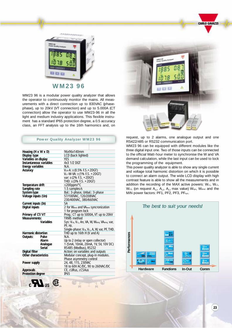
WM23 96 is a modular power quality analyzer that allowsthe operator to continuously monitor the mains. All meas-urements with a direct connection up to 830VAC (phase-phase), up to 20kV (VT connection) and up to 5.000A (CTconnection) allow the operator to use WM23-96 in all thelight and medium industry applications. This flexible instru-ment has a standard IP65 protection degree, a 0.5 accuracyclass, an FFT analysis up to the 16th harmonics and, on
request, up to 2 alarms, one analogue output and oneRS422/485 or RS232 communication port.WM23 96 can be equipped with different modules like thethree digital input one. Two of those inputs can be connectedto the official Watt-hour meter to synchronise the W and VAdemand calculation, while the last input can be used to lockthe programming of the equipment.This power quality analyzer is able to show any single currentand voltage total harmonic distortion on which it is possibleto connect an alarm output. The wide LCD display with highcontrast feature is able to show all the measurements and inaddition the recording of the MAX active powers: WL1, WL2,WL3, (on request AL1, AL2, AL3 max value) Wsys, Wdmd and theMIN power factors: PF1, PF2, PF3, PFsys.
Comm
Power Quality Analyzer WM23 96
96x96x140mmLCD (back lighted)YES4x3 1/2 DGTN.A.VLN-A: ±(0.5% F.S.+2DGT)VLL-W-VA: ±(1% F.S. +2DGT)var: ±(2% F.S. +2DGT)THD: ±(3% F.S. +2DGT)≤200ppm/°C1.5 samples/sBal.: 3-phase, Unbal.: 3-phase57/100VAC, 120/208VAC230/400VAC, 380/660VAC5A2 for Wdmd and VAdmd syncronization1 for program lockProg.: CT up to 5000A, VT up to 20kVTRMS methodSys: VLN, VLL, An, VA, W, Wdmd, VAdmd, var,PF, Hz.Single-phase: VLN, VLL, A, W, var, PF, THD.THD up to 16th H (V and A)N.A.Up to 2 (relay or open collector)1 (5mA, 10mA, 20mA, 1V, 5V, 10V DC)RS485 (Modbus), RS232Action: on variables and outputsModular concept, plug-in modules.Phase asymmetry control24, 48, 115, 230VAC18 to 60V AC/DC, 90 to 260VAC/DCCE, cURus, cCSAusIP65
WM23 96
23

Hardware Functions In-Out
Perf
orm
ance
s
The best to suit your needs!
96x96x140mmLCD (back lighted)YES4x3 1/2 DGT7 1/2 DGTVLN-A: ±(0.5% RDG+1DGT)W-VA: ±(1% RDG+1DGT)Class 1 (EN61036)Class 2 (EN61268)≤200ppm/°C1.5 samples/sBal.: 3-phase, Unbal.: 3-phase57/100VAC, 120/208VAC, 230/400VAC,380/660VAC5A3 for time period management1 for program lockProg.: CT up to 5000A, VT up to 20kVTRMS methodSys: VLN, VLL, VA, W, Wdmd, VAdmd, var, PF, Hz,total varh, partial Wh, partial varh, gas,H2O. Single-phase: VLN, A, VA, W, var, PF.N.A.Up to 2 (open collector or relay)Up to 2 (relay or open collector)N.A.RS485 (Modbus), RS232Action: on variables and outputsModular concept, plug-in modules,phase asymmetry control, energy timeperiod management24, 48, 115, 230VAC18 to 60V AC/DC, 90 to 260VAC/DCCE, cURus, cCSAusIP65
Housing (H x W x D)Display typeVariables on displayInstantaneous variablesEnergy variablesAccuracy
Temperature driftSampling rateSystem typeVoltage inputs (Un)
Current inputs (In)Digital inputs
Primary of CT/VTMeasurements:
Variables
Harmonic distortionOutputs: Pulse
AlarmAnalogueSerial
Digital filterOther characteristics
Power supply
ApprovalsProtection degree
WM24 96 is a modular universal utility meter that allows theoperator to continuously monitor the mains and measureenergy, gas and water by total or partial metering. All meas-urements with a direct connection up to 830VAC (phase-phase), up to 20kV (VT connection) and up to 5.000A (CTconnection) allow the operator to use WM24 96 in all thelight and medium industry applications. This universal utili-ty meter has a standard IP65 protection degree and the
metering of energy is in compliance with class 1 “EN61036”and class 2 “EN61268”.WM24 96 is capable to measure and control, by means ofthe two optional alarm outputs, all the main variables andthe maximum demanded power.It is able to measure and display the total energies in thefour quadrants (+kvar-L, -kvar-L, +kvar-C, -kvar-C). Theaccess to the programming parameters can be locked inorder to avoid undesired modifications.Furthermore the measured energies can be managed bytime period/tariff: t1-t2-t3-t4 by means of two input con-tacts. Those contacts can be used, in alternative, as count-er inputs to measure m3 of gas and water.
Comm
Universal Utility Meter WM24 96
WM24 96
24

Hardware Functions In-Out
Perf
orm
ance
s
The best to suit your needs!
Housing (H x W x D)Display typeVariables on displayInstantantaneous variablesEnergy variablesAccuracyTemperature driftSampling rateSystem typeVoltage inputs (Un)Current inputs (In)Digital inputsPrimary of CT/VTMeasurements:
Variables
Harmonic distortionOutputs: Pulse
AlarmAnalogueSerial
Digital filterOther characteristics
Power supply
ApprovalsProtection degree
Comm
Smart Power Transducer SPT 90
90x90x140mmLEDN.A.N.A.N.A.VLN, A, Hz: 0.5% F.S.≤300ppm/°CResponse time: ≤200msBal.: 1-3-phase Unbal.: 3-phase57/100VAC, 250/433VAC1AAC, 5AACN.A.Prog.: CT up to 5000A, VT up to 100kVTRMS methodSys: V, Amax, VA, W, Wdmd, var, PF, Hz, Wh,varh. Single-phase: VN.A.1 (open collector type or relay)1 (open collector or relay)Up to 2 (5mA, 10mA, 20mA,1V, 5V, 10V DC)RS232N.A.W integration time programming.Parameter programming by means ofremovable key-pad or by RS232,port (with proper Software)18 to 60VAC/DC90 to 260VAC/DCCE, cURus, CSAIP20
SPT 90 is a generation of programmable “smart” trans-ducers, for the measurement of all major characteristics ofan electrical system including power, energy, voltage,current and frequency.The SPT 90 series has a large number of functions availableto the user.Configuration and control can be done in field, interfacingthe transducer at high levels as a remote unit.
SPT 90/SptSoftis a software tool thatcan be used to easilydown-load or upload theprogramming parametersfrom an SPT 90 to a PCand from a PC to a singleSPT.
The advantagesCompared to a traditional transducer SPT 90 offers:• TRMS measurement, that means reliable and true
measurement not affected by distortion• Selection among many types of measurements without
changing the transducer• Wide scaling capability solving the major field application
problems• Combination of analogue and pulse outputs• One integrated transducer with dual analogue output
SPT 90
25
Hardware Functions In-Out
Perf
orm
ance
s
The best to suit your needs!
96x96x140mmGraph LCD back lightedYESSel: 4x3 1/2 DGT or 4x4 DGT4x9 DGT, 4x6 DGTVLN-A:±(0.5 RDG+1DGT)Hz:±0.1% F.S. THD: ±1% F.S.Class 1 (EN61036)Class 2 (EN61268)≤200ppm/°C10 samples/sBal.: 1-3 phase Unbal.: 3-phaseAutoranging 240/415VAC, 400/690VACAutoranging 1/5AAC3 independent for time period synchro.Prog.: CT up to 30000A VT up to 600kVTRMS methodSys:VLN, VLL,An,VA,W,Wdmd, VAdmd, Andmd,PFdmd, var, PF, Hz,Wh, varh.Single-phase: VLN, VLL, A, W, var, PF, THD.THD and single H up to the 50th H (V, A)Up to 4 (open collector type or relay)Up to 4 (open collector or relay)Up to 4 (5mA, 10mA, 20mA, 1V, 5V, 10V DC)RS485 (Modbus), RS232Action: on variables and outputsReal time clock with alarms andMin/Max variable recording. W, VA, PFand An integration time programming.Energy time period management.18 to 60VAC/DC, 90 to 260VAC/DCCE, cURus, CSAIP65
Housing (H x W x D)Display typeVariables on displayInstantaneous variablesEnergy variablesAccuracy
Temperature driftSampling rateSystem typeVoltage inputs (Un)Current inputs (In)Digital inputsPrimary of CT/VTMeasurements:
Variables
Harmonic distortionOutputs: Pulse
AlarmAnalogueSerial
Digital filterOther characteristics
Power supplyApprovalsProtection degree
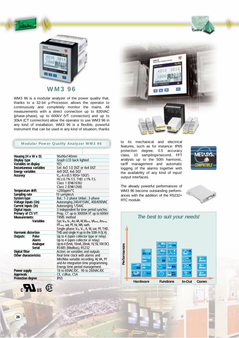
WM3 96 is a modular analyzer of the power quality that,thanks to a 32-bit µ-Processor, allows the operator tocontinuously and completely monitor the mains. Allmeasurements with a direct connection up to 830VAC(phase-phase), up to 600kV (VT connection) and up to30kA (CT connection) allow the operator to use WM3 96 inany kind of installation. WM3 96 is a flexible, powerfulinstrument that can be used in any kind of situation, thanks
to its mechanical and electricalfeatures, such as for instance: IP65protection degree, 0.5 accuracyclass, 10 samplings/second, FFTanalysis up to the 50th harmonic,tariff management and automaticlogging of the alarms together withthe availability of any kind of input/output interfaces.
The already powerful performances ofWM3 96 become outstanding perform-ances with the addition of the RS232+RTC module.
Comm
Modular Power Quality Analyzer WM3 96
WM3 96
26

Main variables
Variables that can be monitored and displayed
System Average Min RS485 Analogue out
VLL, VLN
V asymmetryAAnHzVAvarWPF+kWh (*)-kWh (*)+kvarh (*)-kvarh (*)THD (A-V)THD even (A-V)THD odd (A-V)Single harmonic
Single ph Max Alarm Out Pulse
(*) Total and time-period energies
Analysis of the power quality and control of the electrical parameters
The problems that more frequently occur in electrical systems with:• inverters and power converters;• switching power supplies for computer and communication
system applications;are the following:
• failures on compensation capacitors;• blowing of capacitor fuses;• overheating of power supply transformers with a load
current below the rated value;• overheating of motors and frequent failures;• high neutral conductor currents;• problems on electronic motor controls.
They are mainly due to the harmonic contents of currentsand voltages.The best solution is WM3 96 that allows to continuouslymonitor the harmonic contents of currents and voltagestogether with all other electrical parameters. The control ofmore than one electrical parameter by means of alarm set-points and the automatic recording of events allow theoperator to monitor any anomaly of the installation and ofthe loads in real time, so as to promptly decide and planany maintenance actions, thus avoiding possible damagesto the loads and/or expensive stopping of the machinery.
• Histogram displaying of the harmonic contents relating to every single phase for A and V• Complete harmonic analysis up to the 50th harmonic• Numerical displaying as an absolute and percentage value of the single harmonic• Four-quadrant displaying of the harmonic phase with source detection (generated
harmonics and imported harmonics)
• It’s possible to record up to 480 events that can be the combination of alarms, diagnostics,minimum and maximum value, with reference to: date, time and variable being controlled.
• Energy consumption storage. The RS232+RTC module allows the storage of the energyconsumption of the previous two months.
27

Hardware Functions In-Out
Perf
orm
ance
s
The best to suit your needs!
96x96x140mmGraph LCD back lightedYESSel: 4x3 1/2 DGT or 4x4 DGT4x9 DGT, 4x6 DGTVLN-A: ±(0.5 RDG+1DGT)Hz: ±0.1% F.S. THD: ±1% F.S.Class 1 (EN61036)Class 2 (EN61268)≤200ppm/°C10 samples/sBal.: 1-3 phase Unbal.: 3-phaseAutoranging 240/415VAC, 400/690VACAutoranging 1/5AACUp to 6 independent for time periodsynchronization, Gas and H2O metersProg.: CT up to 30000A VT up to 600kVTRMS methodSys:VLN, VLL,An,VA,W, Wdmd, VAdmd, vardmd,PFdmd, var, PF, Hz,Wh, varh, gas, H2O.Single-phase: VLN, VLL, A, W, var, PF, THD.THD and single H up to the 50th H (V, A)Up to 4 (open collector type)Up to 4 (open collector or relay)N.A.RS485 (Modbus), RS232, EthernetModem-GSM managementAction: on variables and outputsReal time clock with alarms and Min/Max variable recording (2Mb memory).Energy time period and gas, H2Omanagement. Official watt-hour meterinterface.18 to 60VAC/DC, 90 to 260VAC/DCCE, cURus, CSAIP65
Housing (H x W x D)Display typeVariables on displayInstantaneous variablesEnergy variablesAccuracy
Temperature driftSampling rateSystem typeVoltage inputs (Un)Current inputs (In)Digital inputs
Primary of CT/VTMeasurements:
Variables
Harmonic distortionOutputs: Pulse
AlarmAnalogueSerial
Digital filterOther characteristics
Power supplyApprovalsProtection degree
WM4 96 is a Universal Utility meter and Power QualityAnalyzer. This high-tech instrument has been developed tomeet the most advanced application needs. WM4 96 offersto the user many advantages and solutions that can besummarised in:• Load failure prevention by:
quick assembly and maintenance using Plug and Playmodules
harmonic analysis (A/V) with source detection andcontrol; up to 4 alarms for a powerful variable control;alarms logging and data stamping.
• Remote control facilities: up to 4 pulse outputs, RS485port (Modbus RTU), RS232 port.
• Load profile display to keep supply costs under control.• Energy cost allocations with independent import/export
kWh/kvarh and kWh/kvarh multi-tariff management• Water and gas metering and communication using the
same instrument.
Comm
Modular Universal Utility Meter WM4 96
WM4 96
RS232 serial communicationport provided with a 2Mb datamemory.
28

Main variables
Variables that can be monitored and displayed
System Average Min RS485
VLL, VLN
V asymmetryAAnHzVAvarWPF+kWh (*)-kWh (*)+kvarh (*)-kvarh (*)GAS (*)H2OTHD (A-V)THD even (A-V)THD odd (A-V)Single harmonic
Single ph Max Alarm Out Pulse
(*) Total and time-period energies
Powerful variable analysis and great communication capabilities: this is the strength of WM4 96
Official watt-hour meter interface. The 3 interfacing methods of WM4 96 are:• Direct measurement for the power quality analysis (LV or MV/HV connection).• Indirect energy and power measurements by means of official Watt-hour meters
(LV or MV/HV connection).• Direct measurements of the instantaneous variables (LV connection) and indirect
measurements of the energy variables (LV or MV/HV connection).
• Energies-water-gas and instantaneous variables readable on the display of your GSM mobilephone giving you maximum control freedom, saving time and money.
• Alarms transmitted as soon as they occur via GSM or analogue modem notifying the plantabnormal conditions.
• Data logging and stamping of up to 8 programmable instantaneous variables for a time durationup to 90 weeks with date and time references to build up the history of your electrical installation.
• Wm4Soft network communication software to download, manually or automatically (via RS485-analogue modem-GSM modem) up to 2Mb data stored in the WM4 96. This information can besimply plotted in an Excel spreadsheet.
• Continuous data stamping and communication: RS232, RS485, modem, GSM.• Powerful data acquisition by means of Wm4Soft and mobile phones wherever you are.
Mains quality analysis becausethe harmonics are cause ofload failures and productionstop.
Load profile display withalarms to keep the energy con-sumption and power costunder full control.
29
Hardware Functions In-Out
Perf
orm
ance
s
The best to suit your needs!
Housing (H x W x D)Display typeVariables on displayInstantaneous variablesEnergy variablesAccuracy
Temperature driftSampling rateSystem typeVoltage inputs (Un)Current inputs (In)Digital inputs
Primary of CT/VTMeasurements:
Variables
Harmonic distortionOutputs: Pulse
AlarmAnalogueSerial
Digital filterOther characteristics
Power supplyApprovalsProtection degree
Comm
Power Quality Transducer PQT 90
90x90x140mmN.A.N.A.N.A.N.A.VLN-A: ±(0.5%RDG+1DGT)Hz: ±0.1% F.S. THD: ±1%F.S.Class1 (EN61036) Class2 (EN61268)≤200ppm/°Cresponse time:≤200msBal.: 1-3-phase Unbal.: 3-phaseAutoranging: 240/415VAC, 400/690VACAutoranging: 1/5AACUp to 6 independent for synchroand gas, H2O metersProg to: CT 30000A, VT 600kVTRMS methodSys: VLN, VLL, VA, W, Wdmd, VAdmd, vardmd,PFdmd, var, PF, Hz, Wh, varh, gas, H2OSingle phase:VLN, VLL,A,VA,W, var, PF,THD.Up to the 50th H (V and A)Up to 4 (open collector or relay)Up to 4 (open collector or relay)Up to 4 (5mA, 10mA, 20mA, 1V, 5V, 10V DC)RS485 (modbus), RS232, EthernetModem-GSM managementAction: on variables and outputsReal time clock with alarms andMin/Max variable continuos recording(2Mb memory). Energy time period andgas, H2O management. Official watt-hours meter interface.18 to 60VAC/DC, 90 to 260VAC/DCCE, cURus, CSAIP20
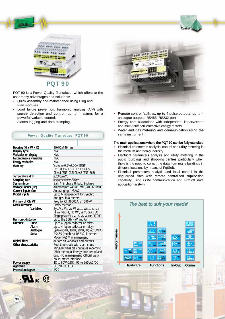
PQT 90 is a Power Quality Transducer which offers to theuser many advantages and solutions:• Quick assembly and maintenance using Plug and
Play modules.• Load failure prevention: harmonic analysis (A/V) with
source detection and control; up to 4 alarms for apowerful variable control;Alarms logging and data stamping.
• Remote control facilities: up to 4 pulse outputs, up to 4analogue outputs, RS485, RS232 port
• Energy cost allocations with independent import/exportand multi-tariff active/reactive energy meters
• Water and gas metering and communication using thesame instrument.
The main applications where the PQT 90 can be fully exploited• Electrical parameters analysis, control and utility metering in
the medium and heavy industry.• Electrical parameters analysis and utility metering in the
public buildings and shopping centres particularly whenthere is the need to collect the data from many buildings indifferent locations by means of PqtSoft.
• Electrical parameters analysis and local control in theunguarded sites with remote centralised supervisioncapability using GSM communication and PqtSoft dataacquisition system.
PQT 90
30
Power variable analysis and great communication capabilities: this is the strength of PQT 90
• Energies-water-gas and instantaneous variables readableon the display of your GSM mobile phone giving youmaximum control freedom, saving time and money.
• Alarms transmitted as soon as they occur via GSM or ana-logue modem, notifying the plant abnormal conditions.
• Data logging and stamping of up to 8 programmable instan-taneous variables for a time duration up to 90 weeks w i t hdate and time references to build up the history of yourelectrical installation.
• PqtSoft Network communication software to download,manually or automatically (via RS485-analogue modemGSM modem), up to 2Mb data stored in the PQT 90.This information can be plotted simply in an Excelspreadsheet.
• Pqt Soft Remote to easily download or upload theprogramming parameters from a PQT 90 to a PC and viceversa.
• Continuous data stamping and communication: RS232,RS485, modem, GSM.
• Powerful data acquisition by means of PqtSoft and mobilephones wherever you are.
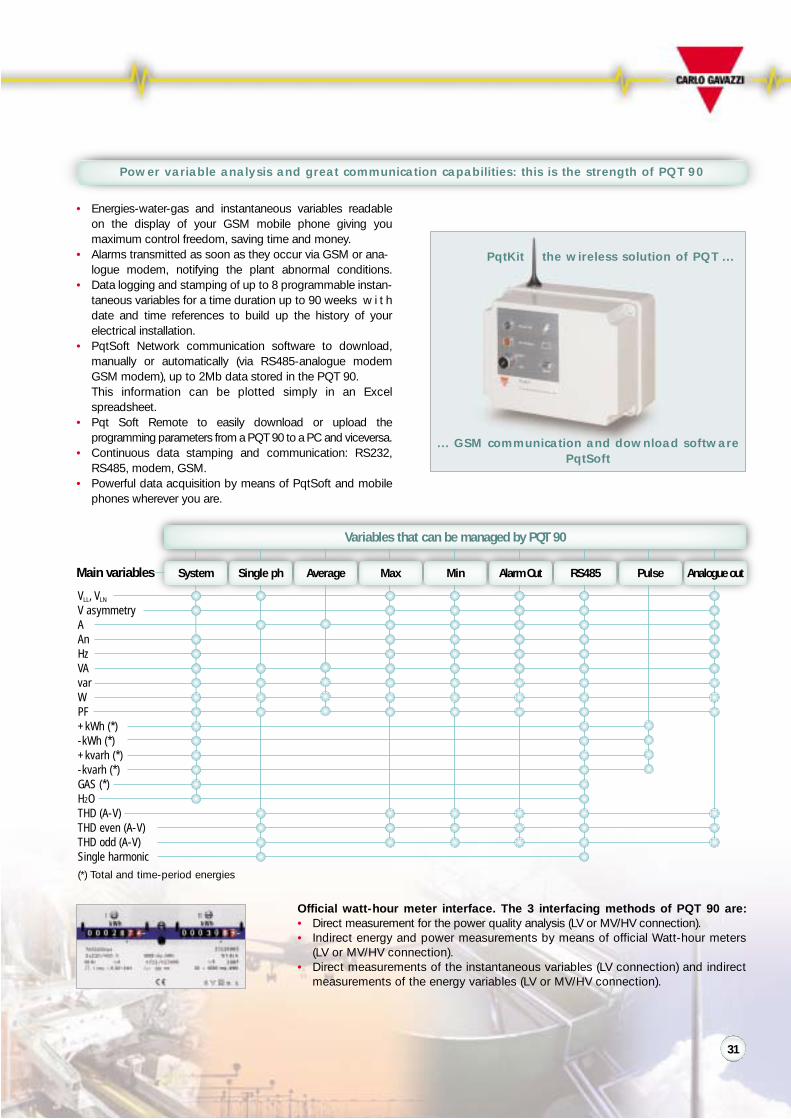
Main variables
Variables that can be managed by PQT 90
System Average Min RS485 Analogue out
VLL, VLN
V asymmetryAAnHzVAvarWPF+kWh (*)-kWh (*)+kvarh (*)-kvarh (*)GAS (*)H2OTHD (A-V)THD even (A-V)THD odd (A-V)Single harmonic
Single ph Max Alarm Out Pulse
Official watt-hour meter interface. The 3 interfacing methods of PQT 90 are:• Direct measurement for the power quality analysis (LV or MV/HV connection).• Indirect energy and power measurements by means of official Watt-hour meters
(LV or MV/HV connection).• Direct measurements of the instantaneous variables (LV connection) and indirect
measurements of the energy variables (LV or MV/HV connection).
(*) Total and time-period energies
PqtKit the wireless solution of PQT ...
... GSM communication and download softwarePqtSoft
31
Ethernet/Internet communicator modulewith WEB server capability. Compatiblewith WM4 and PQTAll the instantaneous single phase andsystem variables of WM4 and PQT exceptfor the harmonics. All the 8 logged variables are displayed in numeric format or,one at a time, as a graph.All the 8 logged variable of WM4 andPQT to TXT format (Excel spread-sheet)IP/ TCP/ HTTP/ TFTP512kbyteRJ45 10 Base TCE, cURus, CSAThe module firmware can be upgradedby LAN or Point to Point connection
Description
Displayable variables
Downloadable variables
ProtocolsWEB page memoryConnectionApprovalsOther characteristics
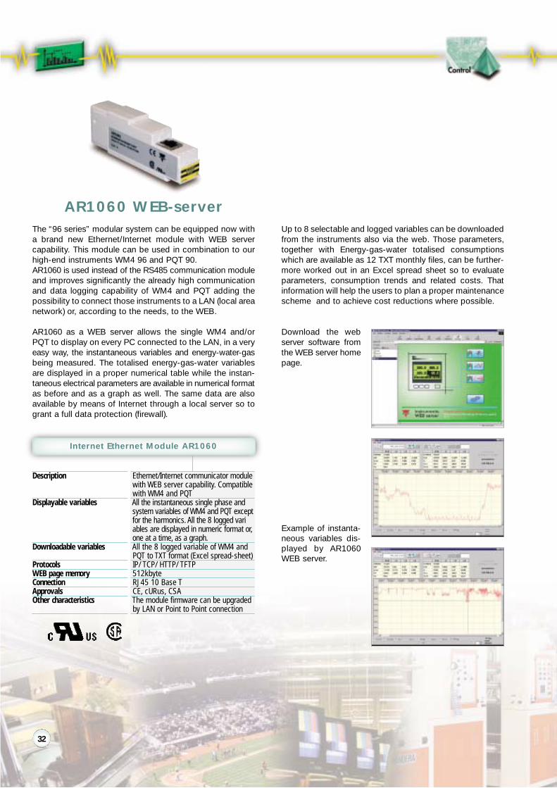
The “96 series” modular system can be equipped now witha brand new Ethernet/Internet module with WEB servercapability. This module can be used in combination to ourhigh-end instruments WM4 96 and PQT 90.AR1060 is used instead of the RS485 communication moduleand improves significantly the already high communicationand data logging capability of WM4 and PQT adding thepossibility to connect those instruments to a LAN (local areanetwork) or, according to the needs, to the WEB.
AR1060 as a WEB server allows the single WM4 and/orPQT to display on every PC connected to the LAN, in a veryeasy way, the instantaneous variables and energy-water-gasbeing measured. The totalised energy-gas-water variablesare displayed in a proper numerical table while the instan-taneous electrical parameters are available in numerical formatas before and as a graph as well. The same data are alsoavailable by means of Internet through a local server so togrant a full data protection (firewall).
Up to 8 selectable and logged variables can be downloadedfrom the instruments also via the web. Those parameters,together with Energy-gas-water totalised consumptionswhich are available as 12 TXT monthly files, can be further-more worked out in an Excel spread sheet so to evaluateparameters, consumption trends and related costs. Thatinformation will help the users to plan a proper maintenancescheme and to achieve cost reductions where possible.
Internet Ethernet Module AR1060
AR1060 WEB-server
Download the webserver software fromthe WEB server homepage.
Example of instanta-neous variables dis-played by AR1060WEB server.
32
89x71.5mmN.A.N.A.N.A.N.A.V, I, Hz: 0.5% F.S.≤200ppm/°CResponse time:≤300ms1-phase100VAC, 500VAC, 60mVDC, 10VDC200VDC1AAC, 5AAC, 1ADCN.A.AllSTDVAC, VDC, AAC, ADC,Hz (45-55Hz, 55-65Hz, 350-450Hz)N.A.N.A.N.A.0-20, 4-20mA; ±1V, 0-10VN.A.N.A.Current or voltage input in the sametransducer. Field adjustment from 50to 130% of the A/V input24VAC, 48VAC, 115VAC, 230VACCEIP40
Housing (H x W)Display typeVariables on displayInstantaneous variablesEnergy variablesAccuracyTemperature driftSampling rateSystem typeVoltage inputs (Un)
Current inputs (In)Digital inputsPrimary of CT/VTMeasurements:
Variables
Harmonic distortionOutputs: Pulse
AlarmAnalogueSerial
Digital filterOther characteristics
Power supplyApprovalsProtection degree
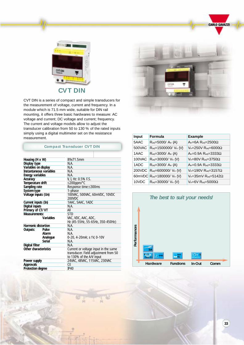
Compact Transducer CVT DIN
CVT DIN is a series of compact and simple transducers forthe measurement of voltage, current and frequency. In amodule which is 71.5 mm wide, suitable for DIN railmounting, it offers three basic hardwares to measure: ACvoltage and current; DC voltage and current; frequency.The current and voltage models allow to adjust thetransducer calibration from 50 to 130 % of the rated inputssimply using a digital multimeter set on the resistancemeasurement.
CVT DIN
Hardware Functions In-Out
Perf
orm
ance
s
The best to suit your needs!
Comm
Input Formula Example
5AAC Radj=5000/ Ain (A) Ain=6A Radj=2500Ω500VAC Radj=1500000/ Vin (V) Vin=250V Radj=6000Ω1AAC Radj=3000/ Ain (A) Ain=0.9A Radj=3333Ω100VAC Radj=30000/ Vin (V) Vin=80V Radj=3750Ω1ADC Radj=3000/ Ain (A) Ain=0.9A Radj=3333Ω200VDC Radj=600000/ Vin (V) Vin=190V Radj=3157Ω60mVDC Radj=180000/ Vin (V) Vin=35mV Radj=5142Ω10VDC Radj=30000/ Vin (V) Vin=6V Radj=5000Ω
33
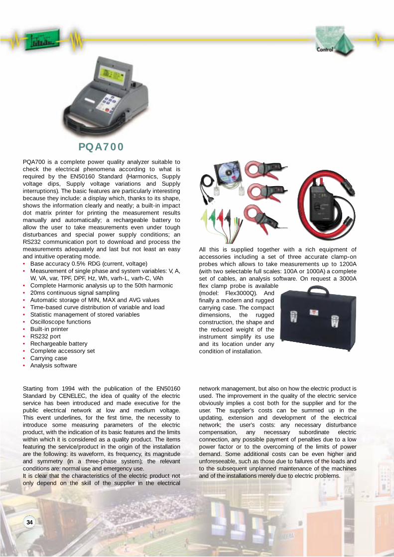
PQA700 is a complete power quality analyzer suitable tocheck the electrical phenomena according to what isrequired by the EN50160 Standard (Harmonics, Supplyvoltage dips, Supply voltage variations and Supplyinterruptions). The basic features are particularly interestingbecause they include: a display which, thanks to its shape,shows the information clearly and neatly; a built-in impactdot matrix printer for printing the measurement resultsmanually and automatically; a rechargeable battery toallow the user to take measurements even under toughdisturbances and special power supply conditions; anRS232 communication port to download and process themeasurements adequately and last but not least an easyand intuitive operating mode.• Base accuracy 0.5% RDG (current, voltage)• Measurement of single phase and system variables: V, A,
W, VA, var, TPF, DPF, Hz, Wh, varh-L, varh-C, VAh• Complete Harmonic analysis up to the 50th harmonic• 20ms continuous signal sampling• Automatic storage of MIN, MAX and AVG values• Time-based curve distribution of variable and load• Statistic management of stored variables• Oscilloscope functions• Built-in printer• RS232 port• Rechargeable battery• Complete accessory set• Carrying case• Analysis software
All this is supplied together with a rich equipment ofaccessories including a set of three accurate clamp-onprobes which allows to take measurements up to 1200A(with two selectable full scales: 100A or 1000A) a completeset of cables, an analysis software. On request a 3000Aflex clamp probe is available(model: Flex3000Q). Andfinally a modern and ruggedcarrying case. The compactdimensions, the ruggedconstruction, the shape andthe reduced weight of theinstrument simplify its useand its location under anycondition of installation.
PQA700
Starting from 1994 with the publication of the EN50160Standard by CENELEC, the idea of quality of the electricservice has been introduced and made executive for thepublic electrical network at low and medium voltage.This event underlines, for the first time, the necessity tointroduce some measuring parameters of the electricproduct, with the indication of its basic features and the limitswithin which it is considered as a quality product. The itemsfeaturing the service/product in the origin of the installationare the following: its waveform, its frequency, its magnitudeand symmetry (in a three-phase system); the relevantconditions are: normal use and emergency use.It is clear that the characteristics of the electric product notonly depend on the skill of the supplier in the electrical
network management, but also on how the electric product isused. The improvement in the quality of the electric serviceobviously implies a cost both for the supplier and for theuser. The supplier’s costs can be summed up in theupdating, extension and development of the electricalnetwork; the user’s costs: any necessary disturbancecompensation, any necessary subordinate electricconnection, any possible payment of penalties due to a lowpower factor or to the overcoming of the limits of powerdemand. Some additional costs can be even higher andunforeseeable, such as those due to failures of the loads andto the subsequent unplanned maintenance of the machinesand of the installations merely due to electric problems.
34

Electrical phenomena
If we briefly go back to thecharacteristics of electric voltage inthe origin of the installation and inorder to closely examine this matter,the Regulation divides these featuresinto two groups;The first one for which somequantitative information are supplied:• Frequency• Harmonic distortion• Phase Asymmetry
The second one for which a fewapproximate data are supplied:• Quick voltage variations• Voltage dips• Supply interruptions• OvervoltagesAll these variables have a directconsequence on the service quality,but also on lines and loads.
The problems The solution
The direct consequences of these phenomena on lines andloads can be underlined as follows:• Failures on compensation capacitors• Blowing of capacitor fuses• Overheating of power supply transformers with load cur-
rent below the rated value• Overheating of motors and frequent failures• High neutral conductor currents• Problems on electronic motor controls• Frequent activation of UPS.
In this case the solution to the monitoring of these electricvariables can have two different proposals depending on theapplication needs:• The first one refers to the occasional analysis and
monitoring of the lines and of some critical charges bymeans of the right instrument, such as PQA700.This analyzer represents therefore the solution accordingto what is required by EN50160.
• The second and more complete proposal refers to thecontinuous monitoring and to the automatic recording ofvarious conditions; these are due either to basicphenomena such as the harmonic contents of currentsand voltages or to the measurements connected toconsumption (current, power, energy, etc.). The latter canbe taken with a flush-mounting instrument, like WM3-96,and can be followed by the subsequent research andlocation of the anomalies by means of a proper measuringand analysis instrument such as PQA700.
The Main Menu
The selection menu of the measuring functions isimmediately available by means of a keypad commandand allows the operator to:• Display the instantaneous measurements• Display the energies• Enable the oscilloscope function• Enable the harmonic analysis• Enable the recording of supply voltage dips• Enable the MIN / AVG/ MAX recording• Set the clock• Program the basic parameters of the instrument
How to order PQA700
PQA70[Clamp type: 2= CA1002, 3X= Flex 3000Q][Language: I, E, F, D, UK][Power Supply: 115V, 230V]See next page: “Accessories”.e.g.: PQA702 UK 230V
PQA702 D 230VPQA703X UK 115V
35

The instantaneous variables are displayed clearly and neatly; moreover they are displayedwith characters at various heights, according to their importance, and they are grouped perpage, by system variables and phase variables so that they can be easily compared amongthem.
Particular attention has been given to the way of displaying the variables: in case of TPFand DPF the values of each phase are displayed together with the FRESNEL diagram.
The energies are displayed: by consumed and exported active, reactive and apparentenergy and by time period.
The behaviour of the current and voltage variables is displayed comparing the relevantwaveforms for each phase. Moreover, also the main instantaneous variables aredisplayed in a numeric form: V-A-TPF-Hz.
The FFT analysis displays the harmonic content in various pages: by phase, current andvoltage. A pointer allows the operator to display for each harmonic the percentage value,the absolute value as a current or voltage and the corresponding harmonic order.
PqaSoft This Windows 95/ 98/ 2000/ XP based software allows the user to downloadall the data acquired by PQA700 during the measuring phase. PqaSoft allows the user, bymeans of icon buttons, to display simply and intuitively the data stored in the memory ofthe instrument; it also allows a graph processing of current and voltage (oscilloscope func-tion) and the displaying of histograms relating to the FFT (harmonic analysis). Other avail-able functions are: management of energy meters by time periods, export of the dataacquired as TXT format files readable by different Windows programs, possibility of instru-ment configuration from the PqaSoft, data logging of up to 20 variables in TXT format filesdirectly on the hard disk of the PC. All the PqaSoft functions are available connectingPQA700 and the PC directly. Furthemore PQA700 allows the user to download the storeddata and to program it by analogue modem.
Display of current andvoltage for each phasewith indication of theharmonic contents.
Display of MIN andMAX values with timereference to the phasevoltage and current, tothe active and apparentpower, to the systempower factor togetherwith the average power.
Real time display of themain variables.
Display of all the ener-gies with reference tothe consumed and tothe exported energies.
36

Portable Power Quality Analyzer PQA700 MAIN FEATURES
DisplayDisplay languageOther indicationsAccuracy
Sampling frequencySampling timeMeasuring inputs
Type of connectionsMeasuring methodAvailable measurements
Data recording
Archives function(by means of PqaSoft)Other functions(by means of PqaSoft)Oscilloscope functionMeasurementsaccording to EN50160Outputs (insulated)PrinterPower supplyApprovalsInstallation CategoryEMC
Operating temperatureStorage temperatureCarrying case / weightStandard accessories
Accessories on request
Type: Graph, 240 x 64 dots (back lighted) Refresh time:500msSelectable: English, Italian, Spanish, German, FrenchBattery recharging by means of a red LED0.5% RDG + 0.15% F.S. (5 to 120% of the voltage range, resolution: 0.1V), 45 to 65Hz0.5% RDG + 0.15% F.S. (5 to 120% of the current range), minimum measurable current: 1A (1mV) , 45 to 65Hz0.05% RDG (frequency). 1% RDG all the other measurements6400Hz @ 50HzFor instantaneous variables: 20ms / continuous. For dips: 10msVoltage measurements: 4 (non-insulated), max. 700VLL RMS. Max peak value: 1600Vp for 1sCurrent measurements: 3 (non-insulated, the insulation is achieved by the clamp-on probes) max. 1.4VACequivalent to 1400A1-phase, 3-phase balanced load, 3-phase unbalanced load, ARON typeTRMS type, crest factor ≤ 3Instantaneous single and system variables:W,VA, var,V,A,TPF, DPF, Hz,THD (voltage, current), odd THD, even THDMaximum demand calculation: W, VA, A (system variables), calculation period: programmable from 1 to 60minutes. Automatic calculation of kvar necessary to compensate low PF FRESNEL diagram indicationMaximum and minimum calculations (single phase and system variables): W, VA, var, V, A, DPF, TPF, Hz,THD (THD is considered for both current and voltage), odd THD, even THD.Energies: + Wh, - Wh, + varh, - varh, +VAh, -VAh (also by time period). FFT analysis (harmonic distortion):histogram indication up to the 50th harmonic, numerical and percentage indication of harmonic contents, ofboth voltage and current. THD (total, odd, even) and single harmonic measurement.FFT voltage range: 2 to 100% F.S.; FFT current range: 5 to 100% F.S.THD calculation according to EN61000-4-7Type: FIFO or stackStart measuring delay: programmable from 00:00h to 23:59hData integration time interval (10ms sampling) : programmable from 1 to 999s (15 min.)Type of recording: minimum, maximum and average value or voltage DIPSData references: date and time (hh:mm:ss)Total available memory: 1MbyteType: stack. Measuring period: fully programmble. Data sampling time: programmable from 10 to 999 s.Type of recording: data sampling of up to 20 selectable variables. Data references: date and time (hh:mm:ss)Statistic management of the stored variablesTime-based curve distribution of variables and loadsCurrent and voltage (current and voltage of single phase available in the same display page) with automatic triggerSupply voltage dips, slow and fast supply voltage variations, supply interruptions
RS232: 9-pole connector, programmable baud rate up to 38400Impact dot matrix type, paper width: 54mm (numerical and graph data printing)230VAC ±15% (115VAC ±15% on request) and internal rechargeable battery power supply (battery life: 1h)CEIII / 600V (according to EN61010-1), double insulationEN61000-4-2 discharge: 8kV “air” level 3, 4kV “contact” level 2; EN61000-4-3 radiated field: 10V/m level 3;EN61000-4-4 transients: 2kV level 3; EN61000-4-5 surge: 2kV; EN50011 conducted emission, class A0 to 55°C (R.H. < 90% non-condensing)-10 to 60°C (R.H. < 90% non-condensing)160 x 340 x 510mm / Instrument: 3.7Kg, the whole set: 10Kg4 voltage measuring cables, length 3m1 RS232 cable1 power supply cable1 analysis software (PqaSoft)1 instruction manual (English, Italian, Spanish, German or French)CA 1002: current clamp probe 100-1000AAC, jaw opening 52mm, cable length 2maccuracy: 0.7% @ 100A, 0.5% @ 1000AFlex3000Q: current clamp probe 3000AAC, flexible type, sensor length 400mm, measuring range: 0,5A to3000A, cable length 2m; accuracy: 1.5% @ 150A, 0.75% @ 1600A, 0.5% @ 3000A
37

Instantaneous variables
All the instantaneous (basic plus additional) variables of all the instruments are dis-played in numerical format with a visual indication of the active alarms and a usefulhour meter function for cost management or maintenance planning purposes. Thealarms are logged in a dedicated and printable page.
Simplified working mode
A limited set of variables is shown for 18 instruments by page. The ON/OFF switchallows to enable or disable the load, resetting the energy values and printing a sim-plified “energy bill” relevant to the selected user.
The graphs
The instantaneous variables are available in a graphical format.Furthermore the demanded power (Wdmd) trend can be alsoshown as a histogram with different colours according to thecurrent tariff. A powerful set of tools is available for a detailedanalysis of the stored information.
Energy ManagementSoftware
The set-up menus
WattSoft can be configured according to the particular needs required by the mon-itored network. Different variables from different instruments can be controlled set-ting the alarms; additional monitored variables can be added to the default ones;automatic data printing can be enabled. All the parameters of the contract can beimplemented for a full energy cost management (single or dual tariff).
WattSoft2 and WattSoft3 combined with our hardware, are the most updated answer to all the power and energy param-eters control needs. WattSoft3 is able to figure-out two basic problems: the management of up to 255 energy meters or poweranalyzers by means of a MODBUS (RS485) linking system; the supervision and control of all the electrical variables beingmeasured in order to optimize the energy consumption and therefore to save money. WattSoft2 is a lighter software packageaddressed to those applications where a limited network (up to 12 instruments) is installed.
38

SMS setting
Up to 8 different SMS can be sent from the instrument in case of alarm activation ordeactivation to up to 5 phone numbers.
Real-time variables
The real-time function allows the display of all the instantaneous vari-ables measured by the instrument and of the total and partial energy,gas and water .
Data download
It is possible to manually or automatically download the logged data from up to 100remote networks composed by maximum 10 WM4 96 or 255 PQT 90 each. The timeperiod between two consecutive automatic downloads is fully configurable from 1day to 1 month. The downloaded data are available for the users in a TXT format soto be used in an Excel spread-sheet for a full analysis .
Instrument configuration
All the working parameters of the instrument can be uploadedaccording to its module composition and to the system to bemonitored. A configuration archive is available in order to storedifferent situations and it is possible to download the currentconfiguration in order to modify it.
Wm4Soft and PqtSoft Remote allow in a very intuitive and fully guided way to configure the instrument, to choose the SMS alarmsand to select the 8 variables to be logged in the 2Mb memory. A real-time table showing all the variables is available too. The PC wherethe software runs can be connected to the instrument by RS232, RS485 (also multi-drop), analogue or GSM modems.
Wm4Soft and PqtSoft Network allow the manual or automatic data download from the 2Mb memory module inserted in theinstrument and the selection of the alarm SMS. A real-time table showing all the variables is available too.The PC where the software runs can be connected to the instrument by RS232, RS485 (also multi-drop), analogue or GSM modems.A phone book is available to call up to 100 instruments allocated in different places.
39
Description
HousingSignal inputWorking modeLine BiasLine terminationConnectionsOutput
Working modeLine BiasLine terminationConnectionsBaud rateProtectionIndication(by means of LEDs)
Insulation
Operating temperature
Storage temperature
Included set
Other characteristics
Power supply input
ApprovalsProtection degree
Accessories
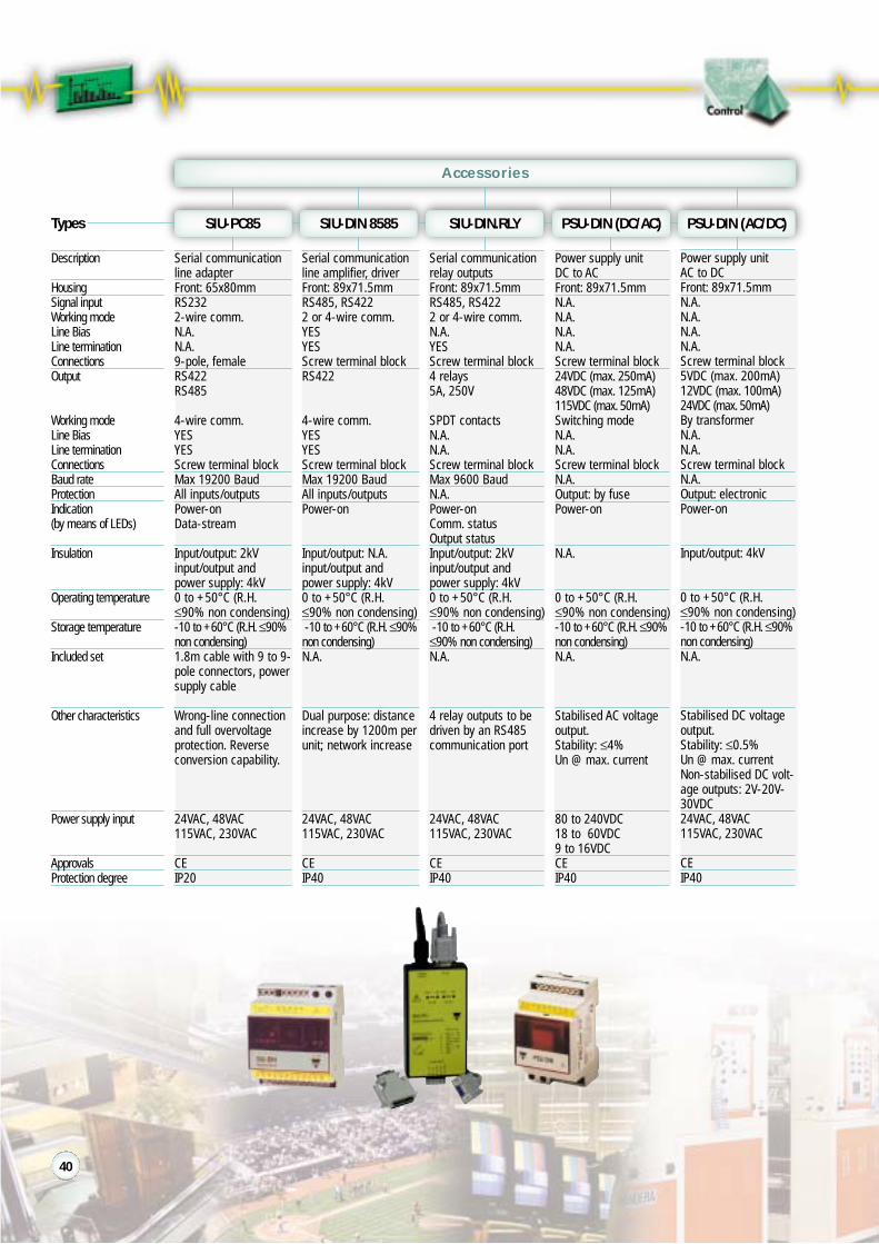
Serial communicationrelay outputsFront: 89x71.5mmRS485, RS4222 or 4-wire comm.N.A.YESScrew terminal block4 relays5A, 250V
SPDT contactsN.A.N.A.Screw terminal blockMax 9600 BaudN.A.Power-onComm. statusOutput statusInput/output: 2kVinput/output andpower supply: 4kV0 to +50°C (R.H.≤90% non condensing)-10 to +60°C (R.H.≤90% non condensing)N.A.
4 relay outputs to bedriven by an RS485communication port
24VAC, 48VAC115VAC, 230VAC
CEIP40
Power supply unitDC to ACFront: 89x71.5mmN.A.N.A.N.A.N.A.Screw terminal block24VDC (max. 250mA)48VDC (max. 125mA)115VDC (max. 50mA)Switching modeN.A.N.A.Screw terminal blockN.A.Output: by fusePower-on
N.A.
0 to +50°C (R.H.≤90% non condensing)-10 to +60°C (R.H.≤90%non condensing)N.A.
Stabilised AC voltageoutput.Stability: ≤4%Un @ max. current
80 to 240VDC18 to 60VDC9 to 16VDCCEIP40
Serial communicationline adapterFront: 65x80mmRS2322-wire comm.N.A.N.A.9-pole, femaleRS422RS485
4-wire comm.YESYESScrew terminal blockMax 19200 BaudAll inputs/outputsPower-onData-stream
Input/output: 2kVinput/output andpower supply: 4kV0 to +50°C (R.H.≤90% non condensing)-10 to +60°C (R.H.≤90%non condensing)1.8m cable with 9 to 9-pole connectors, powersupply cable
Wrong-line connectionand full overvoltageprotection. Reverseconversion capability.
24VAC, 48VAC115VAC, 230VAC
CEIP20
Serial communicationline amplifier, driverFront: 89x71.5mmRS485, RS4222 or 4-wire comm.YESYESScrew terminal blockRS422
4-wire comm.YESYESScrew terminal blockMax 19200 BaudAll inputs/outputsPower-on
Input/output: N.A.input/output andpower supply: 4kV0 to +50°C (R.H.≤90% non condensing)-10 to +60°C (R.H.≤90%non condensing)N.A.
Dual purpose: distanceincrease by 1200m perunit; network increase
24VAC, 48VAC115VAC, 230VAC
CEIP40
Power supply unitAC to DCFront: 89x71.5mmN.A.N.A.N.A.N.A.Screw terminal block5VDC (max. 200mA)12VDC (max. 100mA)24VDC (max. 50mA)By transformerN.A.N.A.Screw terminal blockN.A.Output: electronicPower-on
Input/output: 4kV
0 to +50°C (R.H.≤90% non condensing)-10 to +60°C (R.H.≤90%non condensing)N.A.
Stabilised DC voltageoutput.Stability: ≤0.5%Un @ max. currentNon-stabilised DC volt-age outputs: 2V-20V-30VDC24VAC, 48VAC115VAC, 230VAC
CEIP40
Types SIU-PC85 SIU-DIN 8585 SIU-DIN.RLY PSU-DIN (DC/AC) PSU-DIN (AC/DC)
40

ClassBus–bar sizeDimensions (HxWxD)StandardsPrimary current
ClassBus–bar sizeDimensions (HxWxD)StandardsPrimary current
Types
Split Core Current Transformer
1/ 3/ 0.5 (on request)81 x 51mm155 x 53 x 140 mmBS3938, EN60044-1, DIN42600Burden (VA)Class 0.5 1 3400 A - - 5500 A - 2.5 5600 A 1.5 3.75 7.5750 A 2.5 5/7.5 10800 A 3.75 5/7.5 101000A 5 5 201200A 5/10 5/10/15 201250A 5/10 5/10/15 201500A 5/10/15 10/15/20 301600A 5/10/15 5/10/15/20 30
E.g.: 5/10 5= standard10= on request
1/ 3/ 0.5 (on request)62 x 205mm328 x 50 x 166 mmBS3938, EN60044-1, DIN42600Burden (VA)Class 0.5 1 31000A - 5 7.51200A 1.5 5/7.5 101250A 1.5 1.5/2.5/10 5/151500A 2.5 5/10 152000A 5 5/10/15 202500A 5 5/10/15 203000A 5/10/15 5/10/15/20 304000A 5/10/15 5/10/15/20 305000A 5/10/15/ 5/10/15/ -
30 306000A 5/10/15/ 5/10/15/ -
30 30
E.g.: 5/10 5= standard10= on request
1/ 3/ 0.5 (on request)31 x 26mm100 x 61 x 74 mmBS3938, EN60044-1, DIN42600Burden (VA)Class 0.5 1 3100 A - - 1.5125 A - 1.5 -150 A - - 2.5200 A - 1.5 5250 A - 1.5 5300 A - 1.5 7.5400 A 1.5 5 10
1/ 3/ 0.5 (on request)62 x 127mm248 x 50 x 166 mmBS3938, EN60044-1, DIN42600Burden (VA)Class 0.5 1 3500 A - 2.5 5600 A - 2.5 5/7.5800 A 1.5 5 101000A 2.5 5/10 151200A 5 5/10/15 201250A 5 5/10/15 201500A 5/10 5/10/15 201600A 5/10 5/10/15 202000A 5/10/15 5/10/ -
15/202500A 5/10/ 5/10/ -
15/20 15/303000A 5/10/ 5/10/ -
15/30 15/30
E.g.: 5/10 5= standard10= on request
1/ 3/ 0.5 (on request)51 x 51mm128 x 56 x 104 mmBS3938, EN60044-1, DIN42600Burden (VA)Class 0.5 1 3150 A - - 1.5200 A - 1.5 -250 A - 1.5 3.75300 A - 1.5 5400 A 1.5 2.5 5500 A 2.5 5 10600 A 2.5 5/7.5 15750 A 3.75 5/7.5 -800 A 5 5/10 151000A 5/10 5/10 10
E.g.: 5/10 5= standard10= on request
1/ 3/ 0.5 (on request)62 x 167mm288 x 50 x 166 mmBS3938, EN60044-1, DIN42600Burden (VA)Class 0.5 1 3800 A - 5 7.51000A - 5/7.5 101250A 1.5 5/10 151500A 2.5 5/10/15 201600A 5 5/10/15 302000A 5/10/15 5/10/15/20 302500A - 5/10/15/20 303000A 5/10/15/ 5/10/15/30 -
304000A 5/10/15/ 5/10/15/30 -
30
E.g.: 5/10 5= standard10= on request
SCT74/30 SCT104/50 SCT140/80
Types SCT166/125 SCT166/165 SCT166/205
41
Note: all the products are CE approved.

Cable/Bus–bar type current transformers. Standard output 5A (1A on request). Rated primary currents from 40A to 6000A. DIN–rail or panel mounting. Current trans-former 1-phase AC; operating frequency: 40 to 60 Hz; max system voltage: 0.72 kV; rated insulation level: 3kV/1min @ 50Hz; security factor: ≤5; rated secondary cur-rent: 5A standard (1A on request). All the products are CE approved.
ClassBus–bar sizeDimensions (HxWxD)StandardsAccuracy classdepending on theburden outputPrimary current atrated outputcurrent of 1A/5A
ClassBus–bar sizeDimensions (H xW x D)StandardsAccuracy classdepending on theburden outputPrimary current atrated outputcurrent of 1A/5A
Types
Current Transformer
0.5/ 1/ 320x8 mm98.5x58x44 mmIEC 60185/EN 60185Class 0.5 1 3
BurdenVA VA VA
40A 350A 360A 380A 3100A 3 4150A 3 4 6200A 3 4 6250A 5 8 10300A 5 8 10
0.5/1/5P10127x51 or 102x53 mm183x170x65 mmIEC 60185/EN 60185Class 0.5 1 5P10
BurdenVA VA VA
800A 15 30 101000A 20 40 101200A 30 60 101500A 40 80 102000A 50 100 102500A 60 120 103000A 80 160 104000A 100 200 10
0.5/ 121x14 or 31x11 mm98.5x58x44 mmIEC 60185/EN 60185Class 0.5 1
BurdenVA VA
100A 3150A 3 4200A 3 4250A 5 8300A 5 8400A 6 10500A 6 10600A 6 10
0.5/1/5P10Max 110 mm183x170x 65 mmIEC 60185/EN 60185Class 0.5 1 5P10
BurdenVA VA VA
800A 15 30 101000A 20 40 101500A 40 80 102000A 50 100 102500A 60 120 103000A 80 160 104000A 100 200 10
0.5
115.5x75x44 mmIEC 60185/EN 60185Class 0.5
BurdenVA
1 A 105 A 1010 A 1015 A 1025 A 1040 A 10
0.5/155x24 or 65x20 mm105x145x44 mmIEC 60185/EN 60185Class 0.5 1
BurdenVA VA
400A 6 12500A 6 12600A 10 20800A 10 201000A 20 401200A 20 401500A 30 602000A 30 60
0.525x5 mm115.5x75x44 mmIEC 60185/EN 60185Class 0.5
BurdenVA
1 A 105 A 1010 A 1015 A 1025 A 1040 A 1050A 1060A 1080A 10100A 10150A 10200A 10250A 10
0.5/1/5P1082x32 or 65x34 mm140x120x55 mmIEC 60185/EN 60185Class 0.5 1 5P10
BurdenVA VA VA
400A 4 8 5500A 6 12 5600A 10 20 5800A 15 30 51000A 20 40 51200A 30 50 51500A 40 60 52000A 50 80 52500A 60 100 5
0.5/132x16 or 41x11 mm75x115.5x44 mmIEC 60185/EN 60185Class 0.5 1
BurdenVA VA
100A 3150A 3200A 4250A 6300A 6400A 10500A 10600A 10800A 10
0.5/1/5P10Max 200 mm295x280x45 mmIEC 60185/EN 60185Class 0.5 1 5P10
BurdenVA VA VA
1000A 15 30 101500A 15 30 102000A 15 30 102500A 40 80 103000A 40 80 104000A 50 100 105000A 50 100 106000A 50 100 10
TADK TADK2 TAD 2 TAD 3 TAD 4
Types TAD 6 TAD 8 TAD 12 TACO 110 TACO 200
42

Hardware Functions In-Out
Perf
orm
ance
s
The best to suit your needs!Energy Meters EM1 DIN EM2 DIN/96
89x35mmMechanicalYESN.A5+1 DGT (0.1kW)Class 2 (EN6036)≤200ppm/°C21-phase
230VACIb:15A,Imax: 22.5AACN.A.N.A.
TRMS methodkWh
N.A.1 (open collector)N.A.N.A.N.A.N.A.Start up current50mAAC
Self power supply
CEIP40
Housing (H x W)Display typeVariables on displayInstantaneous variablesEnergy variablesAccuracyTemperature driftSample/sSystem type
Voltage inputs (Un)Current inputs (In)
Digital inputsPrimary of CT/VT
Measurements:Variables
Harmonic distortionOutputs: Pulse
AlarmAnalogueSerial
Digital filter (action)Other characteristics
Power supply
ApprovalsProtection degree
EM1 DIN, EM2 DIN, EM2 96, are energy meters suitable tomeasure the consumed energy in various services andlight/medium industries. These instruments are normallyconnected downstream the official watthours meter tomeasure the energy consumed by machines or depart-ments, in order to split the costs accordingly.EM1 DIN is the electromechanical space-saving solution: inonly 2-DIN module housing there is a reliable active energymeter with optional pulse output.
EM1/EM2 DIN EM2 96
Comm
Hardware Functions In-Out
Perf
orm
ance
s
Comm
EM1 DIN
EM2 DIN/96
EM2 96 and EM2 DIN display the total and partial activeand reactive energy.
89x107/96x96mmLCD back lightedYESN.A.6 DGTClass 1≤200ppm/°C3Bal: 1-3-phaseUnbal: 3-phase250/433VAC5AAC
N.A.CT: progr. up to5000ATRMS methodTotal: kWh, kvarhPartial: kWh, kvarhN.A.N.A.Driven by RS485N.A.N.A.N.A.Only EM2 96:modular concept,plug-in modulesDC power supply24, 48,115, 230VAC96 only: 18 to 60,90 to 260VAC/DCCE, -cURus,CSA (96)-IP40 (DIN)IP65 (96)
96
DIN
16
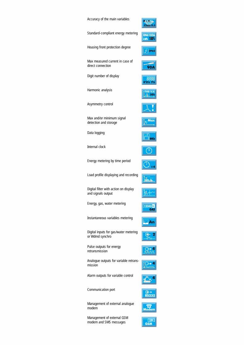
Accuracy of the main variables
Standard-compliant energy metering
Housing front protection degree
Max measured current in case of
direct connection
Digit number of display
Harmonic analysis
Asymmetry control
Max and/or minimum signal
detection and storage
Data logging
Internal clock
Energy metering by time period
Load profile displaying and recording
Digital filter with action on display
and signals output
Energy, gas, water metering
Instantaneous variables metering
Digital inputs for gas/water metering
or Wdmd synchro
Pulse outputs for energy
retransmission
Analogue outputs for variable retrans-
mission
Alarm outputs for variable control
Communication port
Management of external analogue
modem
Management of external GSM
modem and SMS messages