Embed Size (px)
Citation preview

DRAFT
CROSQ Standard
Caribbean Application Document
for the
2018 International Energy Conservation Code
Draft 2018 IECC:REEBC 1
Notice
This draft is subject to change without notice. Recipients of this draft are invited to submit their comments during the designated public comment period.

Copyright Notice
Portions of this document reproduce sections from the 2018 International Codes, International Code Council, Falls Church, Virginia. Reproduced with permission. All rights reserved.
Draft 2018 IECC:REEBC 2

Draft 2018 IECC:REEBC 3

CROSQ Standard
Caribbean Application Document
for the
2018 International Energy Conservation Code
CARICOM Regional Organisation for Standards and Quality2nd Floor Baobab TowersWarrens, St. MichaelBarbadosTel: +1-246-622-7670 / +1-246-622-7677Website: www.crosq.orgE-mail: [email protected]
Month 20xx
Draft 2018 IECC:REEBC iv

20xx CROSQAll rights reserved. Unless otherwise specified, no part of this publication may be reproduced or utilized in any form or by any means, electronic or mechanical, including photocopying and microfilm, without permission in writing from CROQ.
ISBN xxxx-xxxx-xxx
First published Month 20xx
First revision Month 20xx
CROSQ establishes requirements in relation to commodities, processes and practices, but do not purport to include all the necessary provisions of a contract.
The attention of those using this standard specification is called to the necessity of complying with any relevant legislation.
Amendments
Draft 2018 IECC:REEBC ii

COMMERCIAL PROVISIONS.............................................................................................................15CHAPTER 1[CE] SCOPE AND ADMINISTRATION............................................................................15
SECTION C101 SCOPE AND GENERAL REQUIREMENTS..................................................................15C101.1 Title...............................................................................................................................15C101.2 Scope............................................................................................................................ 16C101.3 Intent............................................................................................................................16C101.4 Applicability..................................................................................................................16C101.5 Compliance...................................................................................................................16
SECTION C102 ALTERNATE MATERIALS METHOD OF CONSTRUCTION, DESIGN OR INSULATING SYSTEMS........................................................................................................................................16
C102.1 General.........................................................................................................................16C102.1.1 Above code program.................................................................................................16
SECTION C103 CONSTRUCTION DOCUMENTS...............................................................................16C103.1 General.........................................................................................................................16C103.2 Information on construction documents......................................................................16C103.2.1 Building thermal envelope depiction.........................................................................16C103.3 Examination of documents...........................................................................................16C103.3.1 Approval of construction documents........................................................................16C103.3.2 Previous approvals.....................................................................................................16C103.3.3 Phased approval........................................................................................................16C103.4 Amended construction documents..............................................................................16C103.5 Retention of construction documents..........................................................................16C103.6 Building documentation and closeout submittal requirements...................................16
SECTION C104 FEES...................................................................................................................... 16C104.1 Fees.............................................................................................................................. 16C104.2 Schedule of permit fees................................................................................................16C104.3 Work commencing before permit issuance..................................................................16C104.4 Related fees..................................................................................................................16C104.5 Refunds.........................................................................................................................16
SECTION C105 INSPECTIONS.........................................................................................................16C105.1 General.........................................................................................................................16C105.2 Required inspections....................................................................................................16C105.3 Reinspection.................................................................................................................16C105.4 Approved inspection agencies......................................................................................17C105.5 Inspection requests......................................................................................................17C105.6 Reinspection and testing..............................................................................................17C105.7 Approval....................................................................................................................... 17
SECTION C106 VALIDITY................................................................................................................17C106.1 General.........................................................................................................................17
SECTION C107 REFERENCED STANDARDS.....................................................................................17C107.1 Referenced codes and standards..................................................................................17C107.2 Application of references..............................................................................................17C107.3 Other laws.................................................................................................................... 17
SECTION C108 STOP WORK ORDER...............................................................................................17
Draft 2018 IECC:REEBC iii

C108.1 Authority.......................................................................................................................17C108.2 Issuance........................................................................................................................17C108.3 Emergencies................................................................................................................. 17C108.4 Failure to comply..........................................................................................................17
CHAPTER 2[CE] DEFINITIONS........................................................................................................18SECTION C201 GENERAL................................................................................................................18
C201.1 Scope............................................................................................................................ 18C201.2 Interchangeability.........................................................................................................18C201.3 Terms defined in other codes.......................................................................................18C201.4 Terms not defined........................................................................................................18
SECTION C202 GENERAL DEFINITIONS..........................................................................................18C-FACTOR (THERMAL CONDUCTANCE).....................................................................................18F-FACTOR..................................................................................................................................18COMPUTER ROOM....................................................................................................................18ENERGY USE INTENSITY............................................................................................................18HIGH SPEED DOOR....................................................................................................................18REFRIGERATED WAREHOUSE COOLER...............................................................................18REFRIGERATED WAREHOUSE FREEZER................................................................................18R-VALUE (THERMAL RESISTANCE)............................................................................................18U-FACTOR (THERMAL TRANSMITTANCE)..................................................................................18WALK-IN COOLER......................................................................................................................18WALK-IN FREEZER.....................................................................................................................18
CHAPTER 3[CE] GENERAL REQUIREMENTS...................................................................................19SECTION C301 CLIMATE ZONES.....................................................................................................19
C301.1 General.........................................................................................................................19C301.2 Warm humid locations.................................................................................................19C301.3 Unstated climate zones................................................................................................19
SECTION C302 DESIGN CONDITIONS............................................................................................23C302.1 Interior design conditions.............................................................................................23
SECTION C303 MATERIALS, SYSTEMS AND EQUIPMENT.............................................................23C303.1 Identification.................................................................................................................23C303.1.4 Insulation product rating...........................................................................................23C303.2 Installation....................................................................................................................24C303.3 Maintenance information.............................................................................................24
CHAPTER 4[CE] COMMERCIAL ENERGY EFFICIENCY......................................................................25SECTION C401 GENERAL...............................................................................................................25
C401.1 Scope............................................................................................................................ 25C401.2 Application....................................................................................................................25C401.2.1 Application to replacement fenestration products....................................................25
SECTION C402 Building Envelope Requirements...........................................................................25C402.1 General (Prescriptive)...................................................................................................25C402.1.4.1 Thermal resistance of cold-formed steel walls.......................................................25C402.1.5 Component performance alternative........................................................................25C402.3 Roof solar reflectance and thermal emittance.............................................................29
Draft 2018 IECC:REEBC iv

C402.4 Fenestration (Prescriptive)...........................................................................................30SECTION C403 BUILDING MECHANICAL SYSTEMS.........................................................................33
C403.1 General.........................................................................................................................33C403.1.1 Calculation of heating and cooling loads...................................................................33C403.2 System design (Mandatory)..........................................................................................34C403.3 Heating and cooling equipment efficiencies (Mandatory)............................................35C403.4 Heating and cooling system controls............................................................................36C403.5 Economizers (Prescriptive)...........................................................................................39C403.6 Requirements for complex mechanical systems serving multiple zones......................42C403.7 Ventilation and exhaust systems..................................................................................43C403.8 Fans and fan controls....................................................................................................46C403.9 Heat rejection equipment.............................................................................................49C403.10 Refrigeration equipment performance.......................................................................50C403.11 Construction of HVAC system elements.....................................................................53C403.12 Mechanical systems located outside of the building thermal envelope (Mandatory).56
SECTION C404 SERVICE WATER HEATING (MANDATORY).............................................................68C404.1 General.........................................................................................................................68C404.2 Service water-heating equipment performance efficiency...........................................68C404.3 Heat traps.....................................................................................................................68C404.4 Insulation of piping.......................................................................................................68C404.5 Efficient heated water supply piping............................................................................70C404.5.1 Maximum allowable pipe length method..................................................................70C404.5.2 Maximum allowable pipe volume method................................................................72C404.6 Heated-water circulating and temperature maintenance systems..............................72C404.7 Demand recirculation controls.....................................................................................72C404.8 Drain water heat recovery units...................................................................................72C404.9 Energy consumption of pools and permanent spas. (Mandatory)................................72C404.10 Energy consumption of portable spas (Mandatory)...................................................73C404.11 Service water-heating system commissioning and completion requirements...........73
SECTION C405 ELECTRICAL POWER AND LIGHTING SYSTEMS.......................................................73C405.1 General (Mandatory)....................................................................................................73C405.2 Lighting controls (Mandatory)......................................................................................73C405.3 Interior lighting power requirements (Prescriptive).....................................................74C405.4 Exterior lighting power requirements (Mandatory)......................................................79C405.5 Dwelling electrical meter (Mandatory).........................................................................80C405.6 Electrical transformers (Mandatory)............................................................................80C405.7 Electrical motors (Mandatory)......................................................................................80C405.8 Vertical and horizontal transportation systems and equipment..................................80C405.8.1 Elevator cabs..............................................................................................................80C405.9 Voltage drop in feeders and branch circuits.................................................................80C405.10 Sub-metering (Mandatory).........................................................................................80
SECTION C406 ADDITIONAL EFFICIENCY PACKAGE OPTIONS........................................................84C406.1 Requirements...............................................................................................................84C406.3 Reduced lighting power density...................................................................................84
Draft 2018 IECC:REEBC v

C406.4 Enhanced digital lighting controls.................................................................................84C406.5 On-site renewable energy............................................................................................84C406.6 Dedicated outdoor air system......................................................................................84C406.7 Reduced energy use in service water heating..............................................................84C406.7.1 Load fraction..............................................................................................................84C406.8 Enhanced envelope performance.................................................................................84C406.9 Reduced air infiltration.................................................................................................84
SECTION C407 TOTAL BUILDING PERFORMANCE..........................................................................85C407.1 Scope............................................................................................................................ 85C407.2 Mandatory requirements.............................................................................................85C407.3 Performance-based compliance...................................................................................85C407.4 Documentation.............................................................................................................85C407.6 Calculation software tools............................................................................................86
SECTION C408 SYSTEM COMMISSIONING....................................................................................90C408.1 General.........................................................................................................................90C408.2 Mechanical systems and service water-heating systems commissioning and completion requirements............................................................................................................................90C408.3 Functional testing of lighting controls..........................................................................91
CHAPTER 5 [CE] EXISTING BUILDINGS..........................................................................................92SECTION C501 GENERAL................................................................................................................92
C501.1 Scope............................................................................................................................ 92C501.2 Existing buildings..........................................................................................................92C501.3 Maintenance.................................................................................................................92C501.4 Compliance...................................................................................................................92C501.5 New and replacement materials...................................................................................92C501.6 Historic buildings..........................................................................................................92
SECTION C502 ADDITIONS.............................................................................................................92C502.1 General.........................................................................................................................92C502.2 Prescriptive compliance................................................................................................92C502.2.6 Lighting power and systems......................................................................................92
SECTION C503 ALTERATIONS.........................................................................................................92C503.1 General.........................................................................................................................92C503.2 Change in space conditioning.......................................................................................92C503.3 Building envelope.........................................................................................................92C503.3.1 Roof replacement......................................................................................................92C503.4 Heating and cooling systems........................................................................................92C503.5 Service hot water systems............................................................................................92C503.6 Lighting systems........................................................................................................... 92
SECTION C504 REPAIRS................................................................................................................. 92C504.1 General.........................................................................................................................92C504.2 Application....................................................................................................................92
SECTION C505 CHANGE OF OCCUPANCY OR USE..........................................................................92C505.1 General.........................................................................................................................92
CHAPTER 6 REFERENCED STANDARDS..........................................................................................93
Draft 2018 IECC:REEBC vi
RESIDENTIAL PROVISIONS...............................................................................................................94CHAPTER 1[RE] Scope and Administration...................................................................................94
SECTION R101 SCOPE AND GENERAL REQUIREMENTS..................................................................94R101.1 Title...............................................................................................................................94R101.2 Scope............................................................................................................................94R101.3 Intent............................................................................................................................94R101.4 Applicability..................................................................................................................94R101.4.1 Mixed occupancy.......................................................................................................94R101.5 Compliance...................................................................................................................94R101.5.1 Compliance materials................................................................................................94
SECTION R102 ALTERNATIVE MATERIALS, DESIGN AND METHODS OF CONSTRUCTION AND EQUIPMENT...................................................................................................................................95
R102.1 General.........................................................................................................................95R102.1.1 Above code programs................................................................................................95
SECTION R103 CONSTRUCTION DOCUMENTS...............................................................................95R103.1 General.........................................................................................................................95R103.2 Information on construction documents......................................................................95R103.2.1 Building thermal envelope depiction.........................................................................95R103.3 Examination of documents...........................................................................................95R103.3.1 Approval of construction documents........................................................................95R103.3.2 Previous approvals.....................................................................................................95R103.3.3 Phased approval........................................................................................................95R103.4 Amended construction documents..............................................................................95R103.5 Retention of construction documents..........................................................................95
SECTION R104 INSPECTIONS.........................................................................................................95R104.1 General.........................................................................................................................95R104.2 Required inspections....................................................................................................95R104.2.1 Footing and foundation inspection............................................................................95R104.2.2 Framing and rough-in inspection...............................................................................95R104.2.3 Plumbing rough-in inspection....................................................................................95R104.2.4 Mechanical rough-in inspection................................................................................95R104.2.5 Final inspection..........................................................................................................95R104.3 Reinspection.................................................................................................................95R104.4 Approved inspection agencies......................................................................................95R104.5 Inspection requests......................................................................................................95R104.6 Reinspection and testing..............................................................................................95R104.7 Approval....................................................................................................................... 95
SECTION R105 VALIDITY................................................................................................................95R105.1 General.........................................................................................................................95
SECTION R106 REFERENCED STANDARDS....................................................................................95R106.1 Referenced codes and standards..................................................................................95R106.2 Application of references..............................................................................................95R106.3 Other laws....................................................................................................................95
SECTION R107 FEES...................................................................................................................... 96
Draft 2018 IECC:REEBC vii

R107.1 Fees.............................................................................................................................. 96R107.2 Schedule of permit fees................................................................................................96R107.3 Work commencing before permit issuance..................................................................96R107.4 Related fees..................................................................................................................96R107.5 Refunds.........................................................................................................................96
SECTION R108 STOP WORK ORDER.............................................................................................96R108.1 Authority.......................................................................................................................96R108.2 Issuance........................................................................................................................96R108.3 Emergencies.................................................................................................................96R108.4 Failure to comply..........................................................................................................96
SECTION R109 BOARD OF APPEALS..............................................................................................96R109.1 General.........................................................................................................................96R109.2 Limitations on authority...............................................................................................96R109.3 Qualifications................................................................................................................96
CHAPTER 2[RE] DEFINITIONS.......................................................................................................96SECTION R201 GENERAL................................................................................................................96
R201.1 Scope............................................................................................................................96R201.2 Interchangeability.........................................................................................................96R201.3 Terms defined in other codes.......................................................................................96R201.4 Terms not defined........................................................................................................96
SECTION R202 GENERAL DEFINITIONS..........................................................................................96ENERGY USE INTENSITY............................................................................................................96
CHAPTER 3[RE] General Requirements........................................................................................97SECTION R301 CLIMATE ZONES.....................................................................................................97
R301.1 General.........................................................................................................................97R301.2 Warm humid locations.................................................................................................97R301.3 Unstated climate zones................................................................................................97R301.4 Tropical climate zone....................................................................................................97
SECTION R303 MATERIALS, SYSTEMS AND EQUIPMENT.............................................................97R303.1 Identification................................................................................................................ 97R303.2 Installation....................................................................................................................98R303.3 Maintenance information.............................................................................................98
CHAPTER 4 [RE] RESIDENTIAL ENERGY EFFICIENCY.....................................................................102SECTION R401 GENERAL.............................................................................................................102
R401.1 Scope..........................................................................................................................102R401.2 Compliance.................................................................................................................102
SECTION R402 BUILDING THERMAL ENVELOPE..........................................................................103R402.1 General (Prescriptive).................................................................................................103R402.2 Specific insulation requirements (Prescriptive)..........................................................103R402.3 Fenestration (Prescriptive).........................................................................................106R402.4 Air leakage (Mandatory).............................................................................................107R402.5 Maximum fenestration U-factor and SHGC (Mandatory)...........................................108
SECTION R403 SYSTEMS.............................................................................................................108R403.1 Controls (Mandatory).................................................................................................108
Draft 2018 IECC:REEBC viii

R403.2 Hot water boiler outdoor temperature setback.........................................................108R403.3 Ducts...........................................................................................................................108R403.4 Mechanical system piping insulation (Mandatory).....................................................110R403.5 Service hot water systems..........................................................................................110R403.6 Mechanical ventilation (Mandatory)..........................................................................112R403.7 Cooling equipment (Mandatory)................................................................................112R403.9 Snow melt and ice system controls (Mandatory). Omit section.................................113R403.10 Pools and permanent spa energy consumption.......................................................113R403.11 Portable spas (Mandatory).......................................................................................113R403.12 Residential pools and permanent residential spas...................................................113
SECTION R404 ELECTRICAL POWER AND LIGHTING SYSTEMS.....................................................113RR404.1 Lighting equipment (Mandatory).............................................................................113R404.1.1 Lighting equipment (Mandatory).............................................................................113R404.2 Ceiling fans (mandatory).............................................................................................114
SECTION R405 SIMULATED PERFORMANCE ALTERNATIVE (PERFORMANCE).............................114R405.1 Scope..........................................................................................................................114R405.2 Mandatory requirements...........................................................................................114R405.3 Performance-based compliance.................................................................................114R405.4 Documentation...........................................................................................................114R405.4.2.1 Compliance report for permit application............................................................114R405.5 Calculation procedure................................................................................................114R405.6 Calculation software tools..........................................................................................117
SECTION R406 ENERGY RATING INDEX COMPLIANCE ALTERNATIVE..........................................117R406.1 Scope..........................................................................................................................118R406.2 Mandatory requirements...........................................................................................118R406.3 Energy Rating Index....................................................................................................118R406.4 ERI-based compliance.................................................................................................118R406.5 Verification by approved agency................................................................................118R406.6 Documentation...........................................................................................................118R406.6.1 Compliance software tools......................................................................................118
CHAPTER 5 (RE) EXISTING BUILDINGS........................................................................................119SECTION R501 GENERAL.............................................................................................................120
R501.1 Scope..........................................................................................................................120R501.2 Existing buildings........................................................................................................120R501.3 Maintenance...............................................................................................................120R501.4 Compliance.................................................................................................................120R501.5 New and replacement materials.................................................................................120R501.6 Historic buildings........................................................................................................120
SECTION R502 ADDITIONS..........................................................................................................120R502.1 General.......................................................................................................................120
SECTION R503 ALTERATIONS......................................................................................................120R503.1 General.......................................................................................................................120R503.2 Change in space conditioning.....................................................................................120
SECTION R504 REPAIRS..............................................................................................................120
Draft 2018 IECC:REEBC ix

R504.1 General.......................................................................................................................120R504.2 Application..................................................................................................................120
SECTION R505 CHANGE OF OCCUPANCY OR USE........................................................................120R505.1 General.......................................................................................................................120R505.2 General.......................................................................................................................120
SECTION RA101 SCOPE...............................................................................................................121RA101.1 General.....................................................................................................................121
SECTION RA102 GENERAL DEFINITION.......................................................................................121SOLAR-READY ZONE................................................................................................................121
SECTION RA103 SOLAR-READY ZONE.........................................................................................121RA103.1 General.....................................................................................................................121RA103.2 Construction document requirements for solar- ready zone...................................121RA103.3 Solar-ready zone area...............................................................................................121RA103.4 Obstructions.............................................................................................................121RA103.5 Roof load documentation.........................................................................................121RA103.6 Interconnection pathway.........................................................................................121RA103.7 Electrical service reserved space..............................................................................121RA103.8 Construction documentation certificate..................................................................121
UNITS CONVERSION TABLE........................................................................................................122
Draft 2018 IECC:REEBC x

FOREWORD
Draft 2018 IECC:REEBC 11

INTRODUCTION
The 2018 International Energy Conservation Code (IECC) Caribbean Application Document was developed to promote building efficiency in the Caribbean and other countries in the tropical environment by establishing requirements in the Regional Energy Efficiency Building Code (REEBC) for: Building envelope, cooling system, ventilation, pumping, lighting, and the service water heating systems in buildings. The content of this document is a compendium of technical requirements product of decades of experts working in the Caribbean and other tropical environments around the world.
The climatic conditions of the tropics present many challenges to the built environment, mostly associated to the combined impact of continued exposure to solar ultraviolet radiation and salty moist air. The later promotes the accelerated failure of materials and structures from rebar buried deep inside building walls to exterior roof coatings exposed to outdoor conditions every day. The ultraviolet radiation speeds the breakdown process by evaporating surface moisture and concentrating the salt deposited. As global temperature rises, the tropics stand to be affected by rising sea levels, warmer oceans, and more unpredictable weather patterns. The higher temperatures are associated with growing energy demand from increased air conditioning use.
The Regional Project Team (RPT) came to the decision to move forward with the implementation of the 2018 IECC given the timing advantage of the code review cycle plus some technical updates from the new language that allow for: the use of daylighting, improved room air conditioning requirements, additional maintenance practices, and other benefits.
Draft 2018 IECC:REEBC 12

APPLICABLE VERSION OF THE IECC
This Application Document is based on the 2018 version of the International Energy Conservation Code (IECC). It shall be read in conjunction with this version of the IECC.
Subsequent versions of the IECC may require subsequent versions of this Application Document.
Use and Structure
Users wishing to apply the IECC in CARICOM must first consult this Application Document to get guidance on what applies, alternate compliance paths, additional data and information that applies only to CARICOM.
The structure of this Caribbean application document references only the sections of the IECC which have been amended. The numbering system of the chapters is also maintained as far as is practicable.
Section and sub-section titles and numbering system are maintained according to the following rules:
1. Where there are national requirements, the section and/or sub-section number and title along with the appropriate clause are included in this Application Document. The number and title of sections and sub-sections follow the numbering sequence of the IECC;
DEVELOPMENT
A Regional Project Team (RPT) comprising stakeholders from the CARICOM Member States was first put in place to manage the code development process. The RPT was tasked in in March 2017 to perform the following duties:
1. Review with a view of adopting/adapting/revising the Minimum Energy Performance Standards for Buildings as proposed by the consultant, Solar Dynamics, in their final report of the consultancy Development of Minimum Energy Performance Standard (MEPS) for Public and Commercial Buildings in CARICOM Countries; and
2. Review the International Energy Conservation Code (IECC) with a view of adopting/adapting an appropriate version; and
3. Manage the development of the necessary IECC Application Documents accordingly
4. Develop implementation options for the REEBC.
Draft 2018 IECC:REEBC 13

Draft 2018 IECC:REEBC 14

Figure 1 CROSQ STANDARDS PROJECT WORK PLAN - Regional Energy Efficiency Building Code (REEBC)
Draft 2018 IECC:REEBC 15
ID Task Name Start Finish Duration2017 2018
DecJun Sep MarFeb OctMarJan May FebJanJul AugApr Nov
1 141d8/16/20172/1/2017Committee stage - 30
2 44d4/3/20172/1/2017Review of code by consultant and RPT
3 24d4/3/20173/1/2017Consultant presents findings and recommendations to RPT at first meeting of the RPT
4 3d3/31/20173/29/2017Host first meeting of RPT (face-to-face
5 15d4/21/20174/3/2017Consultant develops Application Documents as necessary
6 45d6/23/20174/24/2017RPT discusses Application Documents and submits comments to consultant as necessary
7 20d7/21/20176/26/2017Consultant amends Application Documents as necessary
8 18d8/16/20177/24/2017Second meeting of RPT to reach consensus (online)
9 120d2/15/20189/1/2017Enquiry stage - 40
10 65d11/30/20179/1/2017Draft Application Document is circulated to MS for public comments
11 33d1/16/201812/1/2017Received comments submitted to consultant for disposition and revises as necessary
12 6d1/24/20181/17/2018Third meeting of RPT (face-to-face validation) to consider revised document RPT accepts
13 5d1/31/20181/25/2018DCRS is finalised and submitted to Crosq secretariat
14 11d2/15/20182/1/2018Editorial Review
15 67d5/4/20182/1/2018Approval stage - 50
16 50d4/11/20182/1/2018FDREEBC is sent to MS for acceptance (VOTING)
17 22d3/30/20183/1/2018TMC considers and recommends to council
21 22d7/31/20187/2/2018Savingram is received FROM caricom Sec.
20
19
18
Apr May
22
15d4/20/20184/2/2018Council decides and recommends to COTED
17d5/4/20184/12/2018COTED decides (report prepared for COTED)
35d8/17/20187/2/2018Publication stage - 60
13d8/17/20188/1/2018Notification is prepared and sent to MS
Jun Jul Aug

List of AbbreviationsCD - Committee DraftCouncil - decision making arm of CROSQ which comprises the directors of the national bureauxDCRS - Draft CARICOM Regional StandardFDCRS - Final Draft CARICOM Regional StandardMS - CARICOM Member StatesNWIP - New Work Item ProposalRTC - Regional Technical Committee - Technical Committee which is made up of stakeholders’ subject experts that are responsible for the development of the draft standardRTC Secretariat - Member State which hosts and coordinates the RTCTMC - Technical Management Committee - this is the technical committee which is made up of technical officers from the various National Bureaux who oversee the standards development processTOS - Technical Officer - responsible for standards at the CROSQ SecretariatWD - Working Draft
ADOPTION
In CARICOM, adoption by Ordinance is not practiced, as Ordinance is considered subsidiary legislation; adoption can only be by Act of Parliament and Regulations. This Caribbean Application Document for the IECC and the associated International Code is legally binding through the enactment of the Building Laws of each CARICOM member state.
MAINTENANCE
The Caribbean Application Documents is intended to be updated no later than 5 years after the completion of the document. CROSQ will participate in the ICC Standards Development and Maintenance programme.
TEXT FORMATTING MODIFICATIONS
The CAD language will be inserted in the language for the IECC sections to be modified. The modified sections will be highlighted with a black bar on the margin side of the text. In the case of the insertion of new section language, said language will be underlined to highlight the code amendment.
REGIONAL PROJECT TEAM REPRESENTATION
The preparation of the Caribbean Application Document for CROSQ, established under CROSQ under Article 67 of the Revised Treaty of Chaguaramas that was signed by the Heads of Government of CARICOM on 5 July 2001, was carried out under the supervision of the Regional Project Team which at the time comprised the following members:
Draft 2018 IECC:REEBC 16
Regional Project Team Members:
Representative Role Member StateMr. Churchill Norbert ChairmanMr. Gurvan Piggott Antigua and BarbudaMr. Mali Barnes Antigua and BarbudaMr. Craig Delancy BahamasMr. Jonathan Platt BarbadosMr. Fabian Scott BarbadosMr. Ryan Cobb BelizeMr. Fred Esprit DominicaMr. Whyme Cox GrenadaMr. Brian Constantine GuyanaMr Nicolas Darius Allien HaitiMrs Kathleen Gregory-Jackson
Jamaica
Mr. Shane Slater JamaicaMr Richard Lawrence JamaicaMr. Stanley Smelie Jamaica
MontserratMr. Vern Emmanuel Saint LuciaMr. David Hird Saint LuciaMr. Rhon Boddie St Kitts and NevisMr. Ellsworth Dacon St Vincent and the GrenadinesMr. Lance Peters St Vincent and the Grenadines
SurinameMs. Nadita Ramachala Trinidad and TobagoMr. Devanand Ragbir Trinidad and Tobago
Representative Role Associate Member StateAnguillaBermudaBritish Virgin IslandsCayman IslandsTurks and Caicos Islands
APPLICATION DOCUMENT UNITS OF MEASUREMENT
Draft 2018 IECC:REEBC 17

This Application Document must use SI measurements
Draft 2018 IECC:REEBC 18

COMMERCIAL PROVISIONS
CHAPTER 1[CE]SCOPE AND ADMINISTRATION
PART 1 - SCOPE AND APPLICATION SECTION C101Draft 2018 IECC:REEBC 19

SCOPE AND GENERAL REQUIREMENTSC101.1 Title. This code shall be known as the 20XX Regional Energy Efficiency Building Code, and shall be cited as such. It is referred to herein as “this code.”
C101.2 Scope.
2018 IECC shall apply.
C101.3 Intent.
2018 IECC shall apply.C101.4 Applicability. 2018 IECC shall apply.
C101.4.1 Mixed occupancy.2018 IECC shall apply.C101.5 Compliance. 2018 IECC shall apply.
C101.5.1 Compliance materials. 2018 IECC shall apply.
SECTION C102 ALTERNATE MATERIALS METHODOF CONSTRUCTION, DESIGN OR
INSULATING SYSTEMSC102.1 General. 2018 IECC shall apply.
C102.1.1 Above code program.
2018 IECC shall apply.
PART 2 - ADMINISTRATION AND ENFORCEMENT
SECTION C103CONSTRUCTION DOCUMENTS
C103.1 General. Construction documents, technical reports and other supporting data shall be submitted in one or more sets with each application for a permit. The construction documents and technical reports shall be prepared by a registered design professional as prescribed by the local jurisdiction or national regulatory authority.
Exception: The code official is
authorized to waive the requirements for construction documents or other supporting data if the code official determines they are not necessary to confirm compliance with this code.
C103.2 Information on construction documents.
2018 IECC shall apply.
C103.2.1 Building thermal envelope depiction.
2018 IECC shall apply.
C103.3 Examination of documents.
2018 IECC shall apply.
C103.3.1 Approval of construction documents.
2018 IECC shall apply.
C103.3.2 Previous approvals.
2018 IECC shall apply.
C103.3.3 Phased approval.
2018 IECC shall apply.
C103.4 Amended construction documents.
2018 IECC shall apply.C103.5 Retention of construction documents. 2018 IECC shall apply.C103.6 Building documentation and closeout submittal requirements. 2018 IECC shall apply.
C103.6.1 Record documents. 2018 IECC shall apply.
C103.6.2 Compliance documentation.
2018 IECC shall apply.
C103.6.3 Systems operation control. 2018 IECC shall apply.
SECTION C104 FEES
Draft 2018 IECC:REEBC 20

C104.1 Fees. 2018 IECC shall apply.C104.2 Schedule of permit fees. 2018 IECC shall apply.C104.3 Work commencing before permit issuance. 2018 IECC shall apply.C104.4 Related fees. 2018 IECC shall apply.C104.5 Refunds. 2018 IECC shall apply.
SECTION C105INSPECTIONS
C105.1 General. 2018 IECC shall apply.C105.2 Required inspections. 2018 IECC shall apply.
C105.2.1 Footing and foundation inspection. 2018 IECC shall apply. C105.2.2 Thermal envelope. 2018 IECC shall apply.C105.2.3 Plumbing system. 2018 IECC shall apply.C105.2.4 Mechanical system. 2018 IECC shall apply.C105.2.5 Electrical system. 2018 IECC shall apply.C105.2.6 Final inspection. 2018 IECC shall apply.
C105.3 Reinspection. 2018 IECC shall apply.C105.4 Approved inspection agencies. 2018 IECC shall apply.C105.5 Inspection requests. 2018 IECC shall apply.C105.6 Reinspection and testing. 2018 IECC shall apply.
C105.7 Approval. 2018 IECC shall apply.C105.7.1 Revocation. 2018 IECC shall apply.
SECTION C106VALIDITY
C106.1 General. 2018 IECC shall apply.
SECTION C107REFERENCED STANDARDS
C107.1 Referenced codes and standards.2018 IECC shall apply.
C107.1.1 Conflicts. 2018 IECC shall apply.C107.1.2 Provisions in referenced codes and standards. 2018 IECC shall apply.
C107.2 Application of references. 2018 IECC shall apply.C107.3 Other laws. The provisions of this code shall not be deemed to nullify any provisions of local, state or national law. If local codes or requirements exceed the requirements set forth in this code, the most current provisions shall apply.
SECTION C108STOP WORK ORDER
C108.1 Authority. 2018 IECC shall apply. C108.2 Issuance. 2018 IECC shall apply.C108.3 Emergencies. 2018 IECC shall apply.C108.4 Failure to comply. 2018 IECC shall apply.
Draft 2018 IECC:REEBC 21

CHAPTER 2[CE]DEFINITIONS
SECTION C201GENERAL
C201.1 Scope. 2018 IECC shall apply. C201.2 Interchangeability. 2018 IECC shall apply.C201.3 Terms defined in other codes.Terms that are not defined in this code but are defined in the International Building Code, International Fire Code, International Fuel Gas Code, International Mechanical Code, International Plumbing Code or the International Residential Code shall have the meanings ascribed to them in those codes.C201.4 Terms not defined. 2018 IECC shall apply.
SECTION C202GENERAL DEFINITIONS
In addition to the definitions provided by IECC, the following shall be included.C-FACTOR (THERMAL CONDUCTANCE).The coefficient of heat transmission (surface to surface) through a build- ing component or assembly, equal to the time rate of heat flow per unit area and the unit temperature difference between the warm side and cold side surfaces (W/(m² · K)) [Btu/h · ft² · °F].F-FACTOR. The perimeter heat loss factor for slab-on-grade floors (W/(m² · K)) [Btu/h · ft² · °F].COMPUTER ROOM. A room whose primary function is to house equipment for the processing and storage of electronic data and that has a design electronic data equipment power density of less than 20 watts per 0.092 m² (20 watts per square foot) of conditioned floor area or a connected design electronic data equipment load of less
than 10 kW.ENERGY USE INTENSITY. Energy-use intensity (EUI): an expression of building energy use per year in terms of net energy divided by gross floorHIGH SPEED DOOR. A non-swinging door used primarily to facilitate vehicular access or material transportation, with a minimum opening rate of 813 mm (32 inches) per second, a minimum closing rate of 610 mm (24 inches) per second and that includes an automatic-closing device.REFRIGERATED WAREHOUSE COOLER. An enclosed storage space capable of being refrigerated to temperatures above 0°C (32°F), that can be walked into and has a total chilled storage area of not less than 279 m² (3,000 square feet).REFRIGERATED WAREHOUSE FREEZER. Anenclosed storage space capable of being refrigerated to temperatures at or below 0°C (32°F) that can be walked into and has a total chilled storage area of not less than 279 m² (3,000 square feet).R-VALUE (THERMAL RESISTANCE). The inverse of the time rate of heat flow through a body from one of its bounding surfaces to the other surface for a unit temperature difference between the two surfaces, under steady state conditions, per unit area ((m² · K)/W) [h · ft² · °F/Btu].U-FACTOR (THERMAL TRANSMITTANCE).The coefficient of heat transmission (air to air) through a building component or assembly, equal to the time rate of heat flow per unit area and unit temperature difference between the warm side and cold side air films (W/(m² · K)) [Btu/h · ft² · °F].
Draft 2018 IECC:REEBC 22

WALK-IN COOLER. An enclosed storage space capable of being refrigerated to temperatures above 0°C (32°F) and less than 12.8°C (55°F) that can be walked into, has a ceiling height of not less than 2 m ( 79 inches ) and has a total chilled storage area of less than 279 m² (3,000 square feet).
WALK-IN FREEZER. An enclosed storage space capable of being refrigerated to temperatures at or below 0°C (32°F) that can be walked into, has a ceiling height of not less than 2 m (79 inches) and has a total chilled storage area of less than 279 m² (3,000 square feet).
CHAPTER 3[CE]GENERAL REQUIREMENTS
SECTION C301CLIMATE ZONES
C301.1 General. Climate zones from Table C301.1 shall be used in determining the applicable requirements from Chapter 4 [CE]. Locations not in Table C301.1 shall be assigned a climate zone based on Section C301.3.C301.2 Warm humid locations. Warm humid locations are identified in Table C301.1 by an asterisk.C301.3 Unstated climate zones. The climate zone for any location not listed in Table C301.1 shall be determined by applying Table C301.3(1) and then Table C301.3(2).C301.4 Tropical climate zone. The tropical climate zone shall be defined as:
1. Anguilla, Antigua and Barbuda, Bahamas, Barbados, Belize, Bermuda, British Virgin Islands, Cayman Islands, Dominica, Grenada, Guyana, Haiti, Jamaica, Montserrat, Saint Lucia, St. Kitts and Nevis, St. Vincent and the Grenadines, Suriname, Trinidad and Tobago, Turks and Caicos Islands; and
2. Islands in the area between the Tropic of Cancer and the Tropic of Capricorn.
Draft 2018 IECC:REEBC 23

TABLE C301.1 CLIMATE ZONES, MOISTURE REGIMES, AND WARM-HUMID DESIGNATIONS BY COUNTRY AND TERRITORY
Key: A – Moist, B – Dry, C – Marine. Absence of moisture designation indicates moisture regime is irrelevant.
CZSI I-P
LOCATION WMO# Elev (m) CDD10 HDD18 Precip (mm) Elev (ft) CDD50 HDD65WALLBLAKE 0A 6691
Antigua and Barbuda (ATG)b VC BIRD INTL AIRPORT 788620 0A 10 6249 0 883 33 11248 0b LYNDEN PINDLING INTL
AIRPORT 780730 1A 7 5643 9 1334 23 10157 16SETTLEMENT POINT 994390 1A 3 5322 19 1281 10 9580 34
Barbados (BRB)b GRANTLEY ADAMS 789540 0A 56 6308 0 1155 184 11354 0BELIZE/PHILLIP GOLD 785830 0A 5 6145 0 1944 16 11061 0
Bermuda (BMU)b BERMUDA INTL 780160 2A 6 4596 88 1456 20 8273 158British Virgin Islands (VGB)a TERRANCE B. LETTSOME INTL AIRPORT 0A 6453 Cayman Islands (CYM)a OWEN ROBERTS AIRPORT 0A 6620 Dominica (DMA)a MELVILLE HALL AIRPORT 0A 6288
b MAURICE BISHOP INTL AIRPORT 789580 0A 7 6378 0 1197 23 11480 0TIMEHRI\CHEDDI JAG 810020 0A 29 6136 0 2234 95 11045 0Port-Au-Prince Aeroport Intl 0A 6848 KINGSTON/NORMAN MAN 783970 0A 14 6608 0 730 46 11894 0MONTEGO BAY/SANGSTE 783880 0A 8 6336 0 1184 26 11405 0
Montserrat (MSR)a JOHN OSBORNE AIRPORT 1A 5946 Saint Lucia (LCA)b HEWANORRA INTL AIRP 789480 0A 10 6429 0 1128 33 11572 0St. Kitts and Nevis (KNA)a 0A 6388 St. Vincent and the Grenadines
ARNOS VALE AIRPORT 0A 6647 Suriname (SUR)b ZANDERIJ 812250 0A 9 6264 0 2249 30 11275 0Trinidad and Tobago (TTO)b ARTHUR NAPOLEON
RAYMOND ROBINSON INTL AIRPORT 789620 0A 6 6307 0 1452 20 11353 0PIARCO INT. AIRPORT 789700 0A 15 6274 0 1781 49 11293 0
Turks and Caicos Islands (TCA)a 0A 6439 a. Calculated CARICOM Member State or Associateb. CARICOM Member State or Associate
(continued)
TABLE C301.1 continuedCLIMATE ZONES, MOISTURE REGIMES, AND WARM-HUMID DESIGNATIONS BY COUNTRY AND TERRITORY
Degree-day: the difference in temperature between the out- door mean temperature over a 24-hour period and a given base temperature. For the purposes of determining building envelope requirements, the classifications are defined as follows:Cooling degree-day base 10°C, CDD10 (50°F, CDD50): for any one day, when the mean temperature is more than10°C (50°F), there are as many degree-days as degrees Fahrenheit or Celsius temperature difference between the mean temperature for the day and 10°C (50°F) (mean temperature 10°C (50°F)). Annual cooling degree- days (CDDs) are the sum of the degree-days over a calendar year.Heating degree-day base 18°C, HDD18 (65°F, HDD65): for any one day, when the mean temperature is less than 18°C (65°F), there are as many degree-days as degrees Fahrenheit or Celsius temperature difference between and 18°C (65°F) and the mean temperature for the day (18°C (65°F) minus the mean temperature). Annual heating degree-days (HDDs) are the sum of the degree-days over a calendar year.
Draft 2018 IECC:REEBC 24

Table 301.3(1)
UNSTATED CLIMATE ZONE DEFINITIONS
MAJOR CLIMATE TYPE DEFINITIONSMarine (C) Definition—Locations meeting all four criteria:1. Mean temperature of coldest month between –3°C (27°F) and 18°C (65°F)2. Warmest month mean < 22°C (72°F)3. At least four months with mean temperatures over 10°C (50°F)4. Dry season in summer. The month with the heaviest precipitation in the cold season has at least
three times as much precipitation as the month with the least precipitation in the rest of the year. The cold season is October through March in the Northern Hemisphere and April through September in the Southern Hemisphere.
Dry (B) Definition—Locations meeting the following criteria:1. Not Marine (C)2. If 70% or more of the precipitation, P, occurs during the high sun period, then the dry/humid
threshold is Pmm < 20.0 × (T + 14) (SI) [Pin < 0.44 × (T – 7) (I-P)]3. If between 30% and 70% of the precipitation, P, occurs during the high sun period, then the
dry/humid threshold is Pmm < 20.0 × (T + 7) (SI) [Pin < 0.44 × (T – 19.5) (I-P)]4. If 30% or less of the precipitation, P, occurs during the high sun period, then the dry/humid
threshold is Pmm < 20 × T (SI) [Pin < 0.44 × (T – 32) (I-P)] where:P = annual precipitation, in. (mm)T = annual mean temperature, °F (°C)
Summer or high sun = April through September in the Northern Hemisphere and October through March period in the Southern Hemisphere
Winter or cold season = October through March in the Northern Hemisphere and April through September in the Southern Hemisphere
Humid (A) Definition—Locations that are not marine and not dry.Warm-humid Definition—Humid (A) locations where either of the following wet-bulb temperature conditions shall occur during the warmestsix consecutive months of the year:1. 19.4°C (67°F ) or higher for 3,000 or more hours; or2. 22.8°C (73°F) or higher for 1,500 or more hours.For IP: °F = [(°F - 32) x 5/9 ], 1 mm = 0.03937 in.
Table 301.3(2)UNSTATED CLIMATE ZONE DEFINITIONS [Source: ASHRAE STANDARD 169-2013]
Thermal Zone
Name SI Units I-P Units
0 Extremely hot 6000 < CDD10°C 10,800 < CDD50°F1 Very hot 5000 < CDD10°C ≤ 6000 9000 < CDD50°F ≤ 10,8002 Hot 3500 < CDD10°C ≤ 5000 6300 < CDD50°F ≤ 90003 Warm CDD10°C ≤3500
and HDD18°C ≤ 2000CDD50°F ≤ 6300and HDD65°F ≤ 3600
Draft 2018 IECC:REEBC 25

Draft 2018 IECC:REEBC 26

SECTION C302 DESIGN CONDITIONS
C302.1 Interior design conditions. The interior design temperatures used for heating and cooling load calculations shall be a maximum of 72°F (22°C) for heating and minimum of 75°F (24°C) for cooling.
SECTION C303 MATERIALS, SYSTEMS AND EQUIPMENT
C303.1 Identification. Materials, systems and equipment shall be identified in a manner that will allow a determination of compliance with the applicable provisions of this code.
C303.1.1 Building thermal envelope insulation. An R- value identification mark shall be applied by the manufacturer to each piece of building thermal envelope insulation 305 mm (12 inches) or greater in width. Alternately, the insulation installers shall provide a certification listing the type, manufacturer and R-value of insulation installed in each element of the building thermal envelope. For blown or sprayed insulation (fiberglass and cellulose), the initial installed thickness, settled thickness, settled R-value, installed density, coverage area and number of bags installed shall be listed on the certification. For sprayed polyurethane foam (SPF) insulation, the installed thickness of the areas covered and R-value of installed thick- ness shall be listed on the certification. For insulated siding, the R-value shall be labelled on the product’s pack- age and shall be listed on the certification. The insulation installer shall sign, date and post the certification in a conspicuous location on the job site.
Exception: For roof insulation installed above the deck, the R-value shall be labeled as required by the material standards specified in Table 1508.2 of the International Building Code.
C303.1.1.1 Blown or sprayed roof/ceiling insulation.
The thickness of blown-in or sprayed roof/ceiling insulation (fiberglass or cellulose) shall be written in mm (inches) on markers that are installed at least one for every 28 m² (300 square feet) throughout the attic space. The markers shall be affixed to the trusses or joists and marked with the minimum initial installed thickness with numbers not less than 25 mm (1 inch) in height.
Each marker shall face the attic access opening. Spray polyurethane foam thickness and installed R-value shall be listed on certification provided by the insulation installer.
C303.1.2 Insulation mark installation. 2018 IECC shall apply.C303.1.3 Fenestration product rating. 2018 IECC shall apply.
TABLE C303.1.3(1)DEFAULT OPAQUE DOOR U-FACTORS
FRAME TYPE
SINGLE PANE
DOUBLE PANE
SKYLIGHTSingle Double
Metal
6.81 W/m²·K
4.54 W/m²·K
11.36 W/m²·K
7.38 W/m²·K
(1.20Btu/h·ft²
·°F)
(0.80Btu/h·ft²
·°F)
(2.00Btu/h·ft²
·°F)
(1.30Btu/h·ft²
·°F)Metal with
Thermal
Break
6.25 W/m²·K
3.69 W/m²·K
10.79 W/m²·K
6.25 W/m²·K
(1.10Btu/h·ft²
·°F)
(0.65Btu/h·ft²
·°F)
(1.90Btu/h·ft²
·°F)
(1.10Btu/h·ft²
·°F)
Nonmetal or Metal Clad
5.39 W/m²·K
3.12 W/m²·K
9.94 W/m²·K
5.96 W/m²·K
(0.95Btu/h·ft²
·°F)
(0.55Btu/h·ft²
·°F)
(1.75Btu/h·ft²
·°F)
(1.05Btu/h·ft²
·°F)Glazed Block
3.41 W/m²·K(0.60 Btu/h·ft²·°F)
C303.1.4 Insulation product rating. The thermal resistance (R-value) of insulation
Draft 2018 IECC:REEBC 27

shall be determined in accordance with the U.S. Federal Trade Commission R-value rule (CFR Title 16, Part 460) in units of h · ft² · °F/Btu at a mean temperature of 24°C (75°F).
TABLE C303.1.3(2) DEFAULT DOOR U-FACTORS
DOOR TYPE U-FACTOR
Uninsulated Metal6.81 W/m²·K
(1.20 Btu/h·ft²·°F)
Insulated Metal (Rolling)5.11 W/m²·K
(0.90 Btu/h·ft²·°F)
Insulated Metal (Other)3.41 W/m²·K
(0.60 Btu/h·ft²·°F)
Wood2.84 W/m²·K
(0.50 Btu/h·ft²·°F)
Insulated, nonmetal edge, max 45% glazing, any glazing double pane
1.99 W/m²·K
(0.35 Btu/h·ft²·°F)
TABLE C303.1.3(3)DEFAULT GLAZED FENESTRATION SHGC AND VT
2018 IECC shall apply.
C303.1.4.1 Insulated siding. 2018 IECC shall apply.
C303.2 Installation. 2018 IECC shall apply.C303.2.1 Protection of exposed foundation insulation. Insulation applied to the exterior of basement walls, crawlspace walls and the perimeter of slab-on-grade floors shall have a rigid, opaque and weather-resistant protective covering to prevent the degradation of the insulation’s thermal performance. The protective covering shall cover the exposed exterior insulation and extend not less than 153 mm (6 inches) below grade.
C303.2.2 Multiple layers of continuous
insulation board. 2018 IECC shall apply.C303.3 Maintenance information. 2018 IECC shall apply.
Draft 2018 IECC:REEBC 28

Draft 2018 IECC:REEBC 29

CHAPTER 4[CE]COMMERCIAL ENERGY EFFICIENCY
SECTION C401 GENERAL
C401.1 Scope. 2018 IECC shall apply.C401.2 Application. 2018 IECC shall apply.
C401.2.1 Application to replacement fenestration products.
2018 IECC shall apply.
SECTION C402BUILDING ENVELOPE REQUIREMENTS
C402.1 General (Prescriptive). 2018 IECC shall apply.
C402.1.1 Low energy use intensity buildings. The following low-energy buildings, or portions thereof separated from the remainder of the building by building thermal envelope assemblies complying with this section, shall be exempt from the building thermal envelope provisions of Section C402.
1. Those with a peak design rate of energy usage less than 10.7 W/m² (3.4 Btu/h ·ft²) or 10.7 W/m² (1.0 watt per square foot) of floor area for space conditioning purposes.
2. Unconditioned space that does not contain habitable space.
3. Greenhouses.C402.1.2 Equipment buildings. Buildings that comply with the following shall be exempt from the building thermal envelope provisions of this code:
1. Are separate buildings with floor area not more than 46.5 m² (500 square feet).
2. Are intended to house electronic equipment with installed equipment power totalling not less than 75 W/m² (7 watts per square foot ) and not intended for human occupancy.
3. Have a heating system capacity not greater than 5 kW (17,000 Btu/hr) and a heating thermostat set point that is restricted to not more than 10°C (50°F).
4. Have an average wall and roof U-factor less than 1.14 W/m²·K (U-0.200 Btu/h·ft²·°F) in Climate Zones 0 through 5 and less than 0.68 W/m²·K (U-0.120 Btu/h·ft²·°F) in Climate Zones 6 through 8.
5. Comply with the roof solar reflectance and thermal emittance provisions for Climate Zones 0 and 1.
C402.1.3 Insulation component R-value-based method. 2018 IECC shall apply.C402.1.4 Assembly U-factor, C-factor or F-factor-based method. Building thermal envelope opaque assemblies shall meet the requirements of Sections C402.2 and C402.4 based on the climate zone specified in Chapter 3. Building thermal envelope opaque assemblies intended to comply on an assembly U-, C- or F-factor basis shall have a U-, C- or F-factor not greater than that specified in Table C402.1.3. Commercial buildings or portions of commercial buildings enclosing Group R occupancies shall use the U-, C- or F-factor from the “Group R” column of Table C402.1.3. Commercial buildings or portions of commercial buildings enclosing occupancies other than Group R shall use
Draft 2018 IECC:REEBC 30

the U-, C- or F-factor.C402.1.4.1 Thermal resistance of cold-formed steel walls. 2018 IECC shall apply.
C402.1.5 Component performance alternative. 2018 IECC shall apply.C402.2 Specific building thermal envelope insulation requirements (Prescriptive). 2018 IECC shall apply.
C402.2.1 Roof assembly. The minimum thermal resistance (R-value) of the insulating material installed either between the roof framing or continuously
Draft 2018 IECC:REEBC 31

Table C402.1.3Building Envelope Requirements for the Tropical Climate Zones*
All other Group R
Opaque Elements Assembly Maximum Insulation Min. R-Value Assembly Maximum Insulation Min. R-Value
Insulation entirely U-0.220 W/m²·K (U-0.039 Btu/h·ft²·°F)
R-4.4 c.i. m²·K/W (R-25 c.i. h·ft²·°F/Btu )
U-0.184 W/m²·K (U-0.032 Btu/h·ft²·°F)
R-4.4 c.i. m²·K/W (R-25 c.i. h·ft²·°F/Btu )
Metal buildinga U-0.233 W/m²·K (U-0.041 Btu/h·ft²·°F)
R-1.8 + R-3.3 FC m²·K/W (R-10 + R-19 FC h·ft²·°F/Btu )
U-0.233 W/m²·K (U-0.041 Btu/h·ft²·°F)
R-1.8 + R-3.3 FC m²·K/W (R-10 + R-19 FC h·ft²·°F/Btu )
Attic and other U-0.153 W/m²·K (U-0.027 Btu/h·ft²·°F)
R-6.7 m²·K/W (R-38 c.i. h·ft²·°F/Btu )
U-0.153 W/m²·K (U-0.027 Btu/h·ft²·°F)
R-6.7 m²·K/W (R-38 c.i. h·ft²·°F/Btu )
Walls, above Grade
U-3.293 W/m²·K (U-0.151 Btu/h·ft²·°F)
NR U-0.857 W/m²·K (U-0.151 Btu/h·ft²·°F)
R-1.0 c.i. m²·K/W (R-5.7 c.i. h·ft²·°F/Btu )
Metal building U-0.533 W/m²·K (U-0.094 Btu/h·ft²·°F)
R-0 + R-1.7 c.i. m²·K/W (R-0 + R-9.8 c.i. h·ft²·°F/Btu )
U-0.533 W/m²·K (U-0.094 Btu/h·ft²·°F)
R-0 + R-1.7 c.i. m²·K/W (R-0 + R-9.8 c.i. h·ft²·°F/Btu )
U-0.705 W/m²·K (U-0.124 Btu/h·ft²·°F)
R-2.3 m²·K/W (R-13 c.i. h·ft²·°F/Btu )
U-0.705 W/m²·K (U-0.124 Btu/h·ft²·°F)
R-2.3 m²·K/W (R-13 c.i. h·ft²·°F/Btu )
Wood-framed and U-0.504 W/m²·K (U-0.089 Btu/h·ft²·°F)
R-2.3 m²·K/W (R-13 c.i. h·ft²·°F/Btu )
U-0.504 W/m²·K (U-0.089 Btu/h·ft²·°F)
R-2.3 m²·K/W (R-13 c.i. h·ft²·°F/Btu )
Wall, below Grade
Below-grade wall C-6.473 W/m²·K (C-1.140 Btu/h·ft²·°F)
NR C-6.473 W/m²·K (C-1.140 Btu/h·ft²·°F)
NR
U-1.825 W/m²·K (U-0.322 Btu/h·ft²·°F)
NR U-1.825 W/m²·K (U-0.322 Btu/h·ft²·°F)
NR
U-1.986 W/m²·K (U-0.350 Btu/h·ft²·°F)
NR U-1.986 W/m²·K (U-0.350 Btu/h·ft²·°F)
NR
Wood-framed and U-1.599 W/m²·K (U-0.282 Btu/h·ft²·°F)
NR U-1.599 W/m²·K (U-0.282 Btu/h·ft²·°F)
NR
Slab-on-Grade Floors
F-1.264 W/m²·K (F-0.730 Btu/h·ft²·°F)
NR F-1.264 W/m²·K (F-0.730 Btu/h·ft²·°F)
NR
F-1.766 W/m²·K (F-1.020 Btu/h·ft²·°F)
R-1.3 m²·K/W (R-7.5 h·ft²·°F/Btu ) for 300 mm (12in.)
F-1.766 W/m²·K (F-1.020 Btu/h·ft²·°F)
R-1.3 m²·K/W (R-7.5 h·ft²·°F/Btu ) for 300 mm (12in.)
Opaque Doors
U-2.101 W/m²·K (U-0.370 Btu/h·ft²·°F)
U-2.101 W/m²·K (U-0.370 Btu/h·ft²·°F)
U-1.760 W/m²·K (U-0.310 Btu/h·ft²·°F)
U-1.760 W/m²·K (U-0.310 Btu/h·ft²·°F)
(continued)
Draft 2018 IECC:REEBC 32
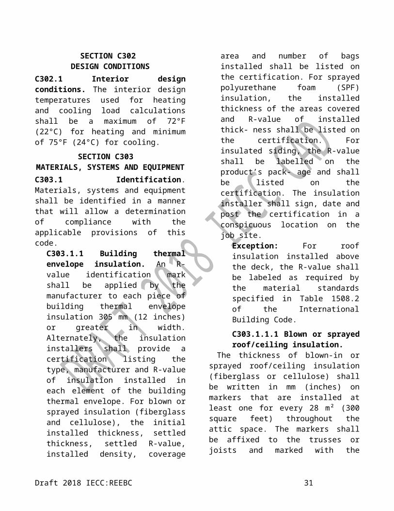
Table C402.1.3 continuedBuilding Envelope Requirements for the Tropical Climate Zone
All other Group R
FenestrationAssembly Max.U
Assembly Max.SHGC
Assembly Min.VT/SHGC
Assembly Max.U
Assembly Max.SHGC
Assembly Min.VT/SHGC
Vertical Fenestration, 0% to 40% of Wall
(for all frame types) (for all frame types)
Nonmetal framing, all U-1.82 W/m²·K (U-0.32 Btu/h·ft²·°F)
0.22 1.1 U-1.82 W/m²·K (U-0.32 Btu/h·ft²·°F)
0.22 1.10
Metal framing, fixed U-2.84 W/m²·K (U-0.50 Btu/h·ft²·°F)
U-2.84 W/m²·K (U-0.50 Btu/h·ft²·°F)
Metal framing, operable U-3.69 W/m²·K (U-0.65 Btu/h·ft²·°F)
U-3.69 W/m²·K (U-0.65 Btu/h·ft²·°F)
Metal framing, entrance door
U-4.71 W/m²·K (U-0.83 Btu/h·ft²·°F)
U-4.71 W/m²·K (U-0.83 Btu/h·ft²·°F)
Skylight, 0% to 3% of Roof
All types U-4.26 W/m²·K (U-0.75 Btu/h·ft²·°F)
0.35 NR U-4.26 W/m²·K (U-0.75 Btu/h·ft²·°F)
0.35 NR
* The following definitions apply: c.i. = insulating material that is continuous across all structural members without thermal bridges other than fasteners and service openings. It is installed on the interior or exterior or is integral to any opaque surface of the building envelope.FC = The first rated R-value of insulation represents faced or unfaced insulation installed between the purlins. The second rated R-value of insulation represents unfaced insulation installed above the first layer, perpendicular to the purlins and compressed when the metal roof panels are attached. A supporting structure retains the bottom of the first layer at the prescribed depth required for the full thickness of insulation. A minimum R-0.9 m²·K/W (R-5.1 h·ft²·°F/Btu) thermal spacer block between the purlins and the metal roof panels is required unless compliance is shown by the overall assembly U-factor.NR = no (insulation) requirement.a. The two R-values are for the separate layers of insulation which must be installed. When using the R-value compliance method for metal building roofs, a thermal spacer block is required.
Table C402.1.4.1EFFECTIVE R-VALUES FOR STEEL STUD WALL ASSEMBLIES
SPACING OF FRAMING
NOMINAL STUD DEPTH
CAVITY R-VALUE (insulation) CORRECTION
FACTOR (Fc)
EFFECTIVE R-VALUE (ER) (Cavity R-Value x
Fc)mm inches mm inches m²·K/W h·ft²·°F/Btu m²·K/W h·ft²·°F/Btu
406 16
89 3.5 2.3 13 0.46 4.98 5.982.6 15 0.43 1.14 6.45
152 6 3.3 19 0.37 1.24 7.033.7 21 0.35 1.29 7.35
203 8 4.4 25 0.31 1.36 7.75
610 24
89 3.5 2.3 13 0.55 1.26 7.152.6 15 0.52 1.37 7.80
152 6 3.3 19 0.45 1.51 8.553.7 21 0.43 1.59 9.03
203 8 4.4 25 0.38 1.67 9.50
Draft 2018 IECC:REEBC 33

on the roof assembly shall be as specified in Table C402.1.3, based on construction materials used in the roof assembly. Insulation installed on a suspended ceiling having removable ceiling tiles shall not be considered as part of the mini- mum thermal resistance of the roof insulation. Continuous insulation board shall be installed in not less than 2 layers and the edge joints between each layer of insulation shall be staggered.
Exceptions:1. Continuously insulated roof assemblies where the thickness of insulation 25 mm (1 inch) or less and where the area-weighted U-factor is equivalent to the same assembly with the R-value specified in Table C402.1.3.2. Where tapered insulation is used with insulation entirely above deck, the R-value where the insulation thickness varies 25 mm (1 inch) or less from the minimum thickness of tapered insulation shall comply with the R-value specified in Table C402.1.3.3. Two layers of insulation are not required where insulation tapers to the roof deck, such as at roof drains.
C402.2.1.1 Skylight curbs. Skylight curbs shall be insulated to the level of roofs with insulation entirely above the deck or R-0.88 (m²·K)/W (R-5 ft²·h·°F/Btu), whichever is less.
Exception: Unit skylight curbs included as a component of a skylight listed and labeled in accordance with NFRC 100 shall not be required to be insulated.
C402.2.2 Above-grade walls. The minimum thermal resistance (R-value) of materials installed in the wall cavity between framing members and continuously on the walls shall be as specified in Table C402.1.3, based on framing type and construction materials used in the wall assembly. The R-value of integral insulation installed in concrete masonry units shall not be used in determining compliance with Table C402.1.3 except as otherwise noted in the table. In determining compliance with Table C402.1.4, the use of the U-factor of concrete masonry units with integral insulation shall be permitted.
“Mass walls” where used as a component in the thermal envelope of a building shall comply with one of the following:
1. Weigh not less than 171 kg/m² (35 pounds per square foot) of wall surface area.2. Weigh not less than 122 kg/m² (25 pounds per square foot) of wall surface area where the material weight is not more than 1900 kg/m3 (120 pcf).3. Have a heat capacity exceeding 144 kJ/m² · K (7 Btu/ft² · °F).4. Have a heat capacity exceeding 103 kJ/m² · K (5 Btu/ft² · °F), where the material weight is not more than 1900 kg/m3 (120 pcf).
C402.2.3 Floors. The thermal properties (component R- values or assembly U-, C- or F-factors) of floor assemblies over outdoor air or unconditioned space shall be as specified in Table C402.1.3 or C402.1.4 based on the construction materials used in the floor assembly. Floor framing cavity insulation or structural slab insulation shall be installed to maintain permanent contact with the underside of the subfloor decking or
Draft 2018 IECC:REEBC 34
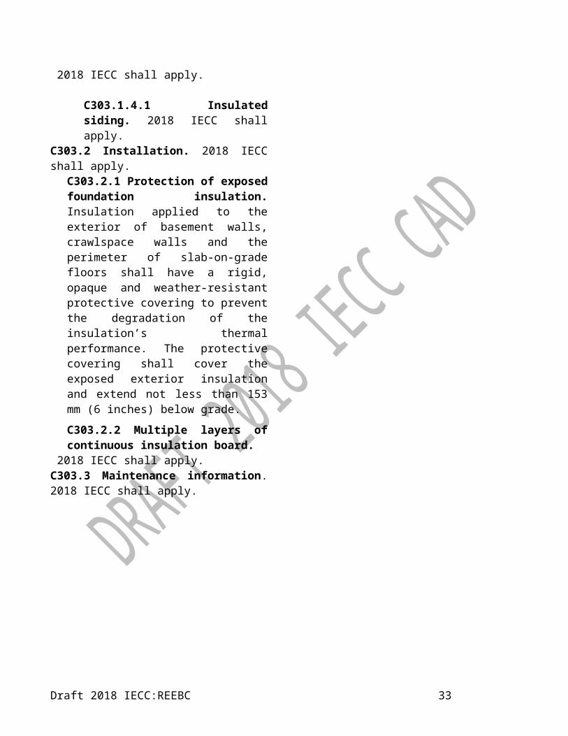
structural slabs.“Mass floors” where used as a component of the thermal envelope of a building shall provide one of the following weights:
1. 171 kg/m² (35 psf) of floor surface area.2. 122 kg/m² (25 psf) of floor surface area where the material weight is not more than 1923 kg/m3 (120 pounds per cubic foot).
Exceptions:1. The floor framing cavity insulation or structural slab insulation shall be permitted to be in contact with the top side of sheathing or continuous insulation installed on the bottom side of floor assemblies where combined with insulation that meets or exceeds the minimum R-value in Table C402.1.3 for “Metal framed” or “Wood framed and other” values for “Walls, Above Grade” and extends from the bottom to the top of all perimeter floor framing or floor assembly members.2. Insulation applied to the underside of concrete floor slabs shall be permitted an airspace of not more than 25 mm (1 inch) where it turns up and is in contact with the underside of the floor under walls associated with the building thermal envelope.
C402.2.4 Slabs-on-grade perimeter insulation. Where the slab on grade is in contact with the ground, the minimum thermal resistance (R-value) of the insulation around the perimeter of unheated or heated slab-on-grade floors designed in accordance with the R-value
method of Section C402.1.3 shall be as specified in Table C402.1.3. The perimeter insulation shall be placed on the outside of the foundation or on the inside of the foundation wall. The perimeter insulation shall extend downward from the top of the slab for the minimum distance shown in the table or to the top of the footing, whichever is less, or downward to not less than the bottom of the slab and then horizontally to the interior or exterior for the total distance shown in the table. Insulation extending away from the building shall be protected by pavement or by not less than of 254 mm (10 inches) of soil.
Exception: Where the slab-on-grade floor is greater than 61 mm (24 inches) below the finished exterior grade, perimeter insulation is not required.
C402.2.5 Below-grade walls. The C-factor for the below- grade exterior walls shall be in accordance with Table C402.1.4. The R-value of the insulating material installed continuously within or on the below-grade exterior walls of the building envelope shall be in accordance with Table C402.1.3. The C-factor or R-value required shall extend to a depth of not less than 3048 mm (10 feet) below the outside finished ground level, or to the level of the lowest floor of the conditioned space enclosed by the below- grade wall, whichever is less.
C402.2.6 Insulation of radiant heating systems. Radiant heating system panels, and their associated components that are installed in interior or exterior assemblies shall be insulated with a minimum of R-0.62 m²/K·W (R-3.5 h·ft²·°F/Btu) on all surfaces not facing the space being heated. Radiant heating system panels that are installed in the building thermal envelope shall be separated from the exterior of the building or unconditioned or exempt spaces by not
Draft 2018 IECC:REEBC 35

less than the R-value of insulation installed in the opaque assembly in which they are installed or the assembly shall comply with Section C402.1.4.
Exception: Heated slabs on grade insulated in accordance with Section C402.2.5.
C402.2.7 Airspaces. 2018 IECC shall apply.C402.3 Roof solar reflectance and thermal emittance. Low-sloped roofs directly above cooled conditioned spaces in Climate Zones 0 through 3 shall comply with one or more of the options in Table C402.3.
Exceptions: The following roofs and portions of roofs are exempt from the requirements of Table C402.3:1. Portions of the roof that include or
are covered by the following:1.1. Photovoltaic systems or
components.1.2. Solar air or water-heating
systems or components.1.3. Roof gardens or landscaped
roofs. 1.4. Above-roof decks or walkways. 1.5. Skylights. 1.6. HVAC systems and components,
and other opaque objects mounted above the roof.
2. Portions of the roof shaded during the peak sun angle on the summer solstice by permanent features of the building or by permanent features of adjacent buildings.
3. Portions of roofs that are ballasted with a minimum stone ballast of 74 kg/m² (17 psf) or 23 psf (117 kg/m² pavers.
4. Roofs where not less than 75 percent of the roof area complies with one or more of the exceptions to this section.
C402.3.1 Aged roof solar reflectance. Where an aged solar
TABLE C402.4BUILDING ENVELOPE FENESTRATION MAXIMUM
U-FACTOR AND SHGC REQUIREMENTS
CLIMATE ZONES 0 AND 1Vertical fenestration
U-factorFixed fenestration 2.84 W/m²·K
(0.50 Btu/h·ft²·°F)Operable fenestration 3.69 W/m²·K
(0.65 Btu/h·ft²·°F)Entrance doors 6.25 W/m²·K
(1.10 Btu/h·ft²·°F)SHGC
Orientationa SEW NPF < 0.2 0.25 0.33
0.2 ≤ PF ≤ 0.5 0.30 0.370.5 ≤ PF 0.40 0.40
SkylightsU-factor 4.26 W/m²·K
(0.75 Btu/h·ft²·°F)SHGC 0.35
NR = No requirement, PF = Projection factor.a. “N” indicates vertical fenestration oriented within 45 degrees of true north. “SEW” indicates orientations other than “N.” For buildings in the southern hemisphere, reverse south and north. Buildings located at less than 23.5 degrees latitude shall use SEW for all orientations.
C402.3.1 Aged roof solar reflectance. 2018 IECC shall apply.
TABLE C402.3MINIMUM ROOF REFLECTANCE AND EMITTANCE
OPTIONS
2018 shall applyC402.4 Fenestration (Prescriptive). 2018 IECC shall apply.
C402.4.1 Maximum area. 2018 IECC shall apply.
C402.4.1.1 Increased vertical fenestration area with daylight responsive controls. In Climate Zones 0 through 4, not more than 40 percent of
Draft 2018 IECC:REEBC 36

the gross above-grade wall area shall be permitted to be vertical fenestration, provided all of the following requirements are met:1. In buildings not greater than two
stories above grade, not less than 50 percent of the net floor area is within a daylight zone.
2. In buildings three or more stories above grade, not less than 25 percent of the net floor area is within a daylight zone.
3. Daylight responsive controls complying with Section C405.2.3.1 are installed in daylight zones.
4. Visible transmittance (VT) of vertical fenestration is not less than 1.1 times solar heat gain coefficient (SHGC).Exception: Fenestration that is outside the scope of NFRC 200 is not required to comply with Item 4.
C402.4.1.2 Increased skylight area with daylight responsive controls. 2018 IECC shall apply.
C402.4.2 Minimum skylight fenestration area. In an enclosed space greater than 232 m² (2,500 square feet) in floor area, directly under a roof with not less than 75 per-cent of the ceiling area with a ceiling height greater than 4572 mm (15 feet), and used as an office, lobby, atrium, concourse, corridor, storage space, gymnasium/exercise centre, convention centre, automotive service area, space where manufacturing occurs, nonrefrigerated warehouse, retail store, distribution/sorting area, transportation depot or workshop, the toplit daylight zone under skylights shall be not less than half the floor area and shall provide one of the following:
1. A minimum skylight area to toplit daylight zone under skylights of
not less than 3 percent where all sky- lights have a VT of at least 0.40 as determined in accordance with Section C303.1.3.2. A minimum skylight effective aperture of at least 1 percent, determined in accordance with Equation 4-4.
Skylight Effective Aperture =0 .85 ⋅Skylight Area⋅Skylight VT⋅WFDaylight zone under skylight
Equation 4-4where:Skylight area = Total fenestration area of skylights.Skylight VT = Area weighted average visible transmittance of skylights.WF = Area weighted average well factor, where well factor is 0.9 if light well depth is less than 610 mm (2 feet), or 0.7 if light well depth is 610 mm (2 feet) or greater.Light well depth = Measure vertically from the underside of the lowest point of the skylight glazing to the ceiling plane under the skylight.
Exception: Skylights above daylight zones of enclosed spaces are not required in:
1. Spaces where the designed general lighting power densities are less than 5.4 W/m² (0.5 W/ft²).2. Areas where it is documented that existing structures or natural objects block direct beam sun- light on at least half of the roof over the enclosed area for more than 1,500 daytime hours per year between 8 a.m. and 4 p.m.3. Spaces where the daylight zone under rooftop monitors is greater than 50 percent of the enclosed
Draft 2018 IECC:REEBC 37

space floor area.4. Spaces where the total area minus the area of daylight zones adjacent to vertical fenestration is less than 232 m² (2,500 square feet), and where the lighting is controlled according to Section C405.2.5.
C402.4.2.1 Lighting controls in daylight zones under skylights. 2018 IECC shall apply.C402.4.2.2 Haze factor. 2018 IECC shall apply.
C402.4.3 Maximum U-factor and SHGC. 2018 IECC shall apply.
C402.4.3.1 Increased skylight SHGC. In Climate Zones 0 through 6, skylights shall be permitted a maximum SHGC of 0.60 where located above daylight zones provided with daylight responsive controls.C402.4.3.2 Increased skylight U-factor. Where skylights are installed above daylight zones provided with daylight responsive controls, a maximum U-factor of 0.9 shall be permitted in Climate Zones 0 through 3 and a maximum U-factor of 4.26 W/m²·K (0.75 Btu/h·ft²·°F) shall be permitted in Climate Zones 4 through 8.C402.4.3.3 Dynamic glazing. 2018 IECC shall apply.C402.4.3.4 Area-weighted U-factor. 2018 IECC shall apply.
C402.4.4 Daylight zones. 2018 IECC shall apply.
C02.4.5 Doors. 2018 IECC shall apply.C402.5 Air leakage—thermal envelope (Mandatory). The thermal envelope of buildings shall comply with Sections C402.5.1 through C402.5.8, or the building thermal envelope shall be tested in accordance with ASTM E 779 at a pressure differential of 75 Pa (0.3 inch water gauge) or an equivalent method
approved by the code official and deemed to comply with the provisions of this section when the tested air leakage rate of the building thermal envelope is not greater than 0.2 L/s · m² (0.40 cfm/ft²). Where compliance is based on such testing, the building shall also comply with Sections C402.5.5, C402.5.6 and C402.5.7.
C402.5.1 Air barriers. 2018 IECC shall apply.C402.5.1.1 Air barrier construction. 2018 IECC shall apply.C402.5.1.2 Air barrier compliance options. 2018 IECC shall apply.
C402.5.1.2.1 Materials. Materials with an air permeability not greater than 0.02 L/s · m² (0.004 cfm/ft²) under a pressure differential of 75 Pa (0.3 inch water gauge) when tested in accordance with ASTM E 2178 shall comply with this section. Materials in Items 1 through 16 shall be deemed to comply with this section, provided joints are sealed and materials are installed as air barriers in accordance with the manufacturer’s instructions.
1. Plywood with a thickness of not less than 10 mm (3/8 inch).2. Oriented strand board having a thickness of not less than 10 mm (3/8 inch). 3. Extruded polystyrene insulation board having a thickness of not less than 12.7 mm (1/2 inch). 4. Foil-back polyisocyanurate insulation board having a thickness of not less than 12.7 mm (1/2 inch).5. Closed-cell spray foam a minimum density of 2.4 kg/m3
(1.5 pcf) having a thickness of not less than 38 mm (11/2 inches).
Draft 2018 IECC:REEBC 38

6. Open-cell spray foam with a density between 0.4 and 1.5 pcf (0.6 and 2.4 kg/m3) and having a thickness of not less than 113 mm (4.5 inches).7. Exterior or interior gypsum board having a thickness of not less than 12.7 mm (1/2 inch).8. Cement board having a thickness of not less than 12.7 mm (1/2 inch).9. Built-up roofing membrane.10. Modified bituminous roof membrane.11. Fully adhered single-ply roof membrane.12. A Portland cement/sand parge, or gypsum plaster having a thickness of not less than 15.9 mm (5/8 inch).13. Cast-in-place and precast concrete.14. Fully grouted concrete block masonry.15. Sheet steel or aluminium.16. Solid or hollow masonry constructed of clay or shale masonry units.
C402.5.1.2.2 Assemblies. Assemblies of materials and components with an average air leakage not greater than 0.2 L/s · m² (0.04 cfm/ft²) under a pressuredifferential of 75 Pa (0.3 inch of water gauge (w.g.)) when tested in accordance with ASTM E 2357,ASTM E 1677 or ASTM E 283 shall comply with this section. Assemblies listed in Items 1 through 3 shall be deemed to comply, provided joints are sealed and the requirements of Section C402.5.1.1 are met.
1. Concrete masonry walls
coated with either one application of block filler or two applications of a paint or sealer coating.2. Masonry walls constructed of clay or shale masonry units with a nominal width of 4 inches (102 mm) or more.3. A Portland cement/sand parge, stucco or plaster not less than 12.7 mm (1/2 inch) in thickness.
C402.5.2 Air leakage of fenestration. 2018 IECC shall apply.C402.5.3 Rooms containing fuel-burning appliances. 2018 IECC shall apply.C402.5.4 Doors and access openings to shafts, chutes, stairways and elevator lobbies. 2018 IECC shall apply.C402.5.5 Air intakes, exhaust openings, stairways and shafts. 2018 IECC shall apply.C402.5.6 Loading dock weatherseals. 2018 IECC shall apply.C402.5.7 Vestibules. Building entrances shall be protected with an enclosed vestibule, with all doors opening into and out of the vestibule equipped with self-closing devices. Vestibules shall be designed so that in passing through the vestibule it is not necessary for the interior and exterior doors to open at the same time. The installation of one or more revolving doors in the building entrance shall not eliminate the requirement that a vestibule be provided on any doors adjacent to revolving doors.
Exceptions: Vestibules are not required for the following:
1. Buildings in Climate Zone 2.2. Doors not intended to be used by
the public, such as doors to mechanical or electrical equipment rooms, or intended solely for employee use.
Draft 2018 IECC:REEBC 39

3. Doors opening directly from a sleeping unit or dwelling unit.
4. Doors that open directly from a space less than 298 m² (3,000 square feet) in area.
5. Revolving doors.6. Doors that have an air curtain with a
velocity of not less than 6.56 feet per second (2 m/s) at the floor that have been tested in accordance with ANSI/AMCA 220 and installed in accordance with the manufacturer’s instructions. Manual or automatic controls shall be provided that will operate the air curtain with the opening and closing of the door. Air curtains and their controls shall comply with Section C408.2.3.
C402.5.8 Recessed lighting. Recessed luminaires installed in the building thermal envelope shall be all of the following:
1. IC-rated.2. Labeled as having an air leakage rate of not more 0.944 L/s (2.0 cfm) when tested in accordance with ASTM E 283 at a 75 Pa (1.57 psf) pressure differential.3. Sealed with a gasket or caulk between the housing and interior wall or ceiling covering.
SECTION C403BUILDING MECHANICAL SYSTEMS
C403.1 General. 2018 IECC shall apply.
C403.1.1 Calculation of heating and cooling loads.
Design loads associated with heating, ventilating and air conditioning of the building shall be determined in accordance with ANSI/ASHRAE/ACCA Standard 183, ACCA Manual N, or by an approved equivalent computational procedure using the design parameters specified in Chapter 3. Heating and
cooling loads shall be adjusted to account for load reductions that are achieved where energy recovery systems are utilized in the HVAC system in accordance with the ASHRAE HVAC Systems and Equipment Handbook by an approved equivalent computational procedure.
Design loads shall be attached to the code compliance form submitted to the building department when the building is permitted or, in the event the mechanical permit is obtained at a later time, the sizing calculation shall be submitted with the application for the mechanical permit.
Exception: Where mechanical systems are designed by a registered engineer, the engineer has the option of submitting a signed and sealed summary sheet to the building department in lieu of the complete sizing calculation(s). Such summary sheet shall include the following (by zone):1. Project name/owner2. Project address3. Area in meters4. Sizing method used5. Indoor dry bulb6. Relative humidity7. Outdoor wet bulb used8. Outdoor dry bulb used9. Grains water (difference)10. Total sensible gain11. Total latent gain12. Total cooling required with outside
air13. Total heating required with outside
airC403.2 System design (Mandatory). 2018 IECC shall apply.
Draft 2018 IECC:REEBC 40

TABLE C402.5.2MAXIMUM AIR LEAKAGE RATE
FOR FENESTRATION ASSEMBLIES
FENESTRATION ASSEMBLY
MAXIMUM RATE a TEST PROCEDURE
L/s (CFM/FT²)
Windows 0.09ª 0.20ª
AAMA/WDMA/ CSA101/I.S.2/A440
or NFRC 400
Sliding doors 0.09ª 0.20 ª
Swinging doors 0.09ª 0.20 ªSkylights – with condensation weepage openings
0.14 0.30
Skylights – all other 0.09ª 0.20 ª
Curtain walls 0.03 0.06
NFRC 400 or ASTM E 283 at 75 Pa
(1.57 psf)
Storefront glazing 0.03 0.06
Commercial glazed swinging entrance doors
0.47 1.00
Power-operated sliding doors and power-operated folding doors
0.47 1.00
Revolving doors 0.47 1.00
Garage doors 0.19 0.40 ANSI/DASMA 105, NFRC 400 or ASTM
E 283 at 75 Pa (1.57 psf)
Rolling doors 0.47 1.00High-speed doors 0.61 1.3
a. The maximum rate for windows, sliding and swinging doors, and skylights is permitted to be 0.14 L/s (0.3 cfm) per 0.093 m² (square foot) of fenestration or door area when tested in accordance with AAMA/WDMA/CSA101/I.S.2/A440 at 300 Pa (6.24 psf).
C403.2.1 Zone isolation required (Mandatory).
HVAC systems serving zones that are over 2323 m² square feet (25,000) in floor area or that span more than one floor and are designed to operate or be occupied non-simultaneously shall be divided into isolation areas. Each isolation area shall be equipped with isolation devices and controls configured to automatically shut off the supply of conditioned air and outdoor air to and exhaust air from the isolation area. Each isolation area shall be
controlled independently by a device meeting the requirements of Section C403.4.2.2. Central systems and plants shall be provided with controls and devices that will allow system and equipment operation for any length of time while serving only the smallest isolation area served by the system or plant.
Exceptions:1. Exhaust air and outdoor air connections to isolation areas where the fan system to which they connect is not greater than 2360 L/s (5,000 cfm).2. Exhaust airflow from a single isolation area of less than 10 percent of the design airflow of the exhaust system to which it connects.3. Isolation areas intended to operate continuously or intended to be inoperative only when all other isolation areas in a zone are inoperative.
C403.2.2 Ventilation (Mandatory). 2018 IECC shall apply.C403.3 Heating and cooling equipment efficiencies (Mandatory). 2018 IECC shall apply.
C403.3.1 Equipment sizing. 2018 IECC shall apply.
C403.3.2 HVAC equipment performance requirements (Mandatory).
Equipment shall meet the minimum efficiency requirements of Tables C403.2.3(1) through C403.2.3(11) when tested and rated in accordance with the applicable test procedure. Plate-type liquid-to-liquid heat exchangers shall meet the minimum requirements of Table C403.2.3(10). The efficiency shall be verified through certification under an approved certification program or, where a certification program does not exist, the equipment efficiency ratings shall be supported by data furnished by the manufacturer.
performance requirements are provided,
Draft 2018 IECC:REEBC 41

the equipment shall satisfy all stated requirements. Where components, such as indoor or outdoor coils, from different manufacturers are used, calculations and supporting data shall be furnished by the designer that demonstrates that the combined efficiency of the specified components meets the requirements herein.
C403.3.2.1 Water-cooled centrifugal chilling packages (Mandatory). Equipment not designed for operation at AHRI Standard 550/590 test conditions of 7°C (44°F) leaving chilled-water temperature and 0.04 mL/J (2.4 gpm/ton) evaporator fluid flow and 29°C (85°F) entering condenser water temperature with 0.054 L/s • kW (3 gpm/ton) condenser water flow shall have maximum full-load kW/ton (FL) and part-load ratings requirements adjusted using Equations 4-6 and 4-7.FLadj = FL/Kadj
Equation 4-6
PLVadj = IPLV/Kadj
Equation 4-7
where:
Kadj = A × BFL = Full-load kW/ton value as
specified in Table C403.2.3(7).FLadj = Maximum full-load kW/ton
rating, adjusted for nonstandard conditions.
IPLV = Value as specified in Table C403.2.3(7).
PLVadj = Maximum NPLV rating, adjusted for non-standard conditions.
A = 0.00000014592 · (LIFT)4 – 0.0000346496 · (LIFT)3 + 0.00314196 · (LIFT)2 –
0.147199 · (LIFT) + 3.9302B = 0.0015 · LvgEvap + 0.934LIFT = LvgCond – LvgEvapLvgCond = Full-load condenser
leaving fluid temperature (°F).
LvgEvap = Full-load evaporator leaving temperature (°F).
The FLadj and PLVadj values are only applicable for centrifugal chillers meeting all of the following full- load design ranges:
1. Minimum evaporator leaving temperature: 2°C (36°F).2. Maximum condenser
leaving temperature: 46°C (115°F).3. -7°C (20°F) ≤ LIFT ≤ 27°C (80°F).
C403.3.2.2 Positive displacement (air- and water-cooled) chilling packages. Equipment with a leaving fluid temperature higher than 0°C (32°F) and water-cooled positive displacement chilling packages with a condenser leaving fluid temperature below 46°C (115°F) shall meet the requirements of Table C403.2.3(7) when tested or certified with water at standard rating conditions, in accordance with the referenced test procedure.
C403.3.3 Hot gas bypass limitation. 2018 IECC shall apply.
TABLE C403.3.3MAXIMUM HOT GAS BYPASS CAPACITY
RATED CAPACITYkW (Btu/h)
MAXIMUM HOT GAS BYPASS CAPACITY
(% of total capacity)≤ 70kW (240,000 Btu/h) 50> 70 kW (240,000 Btu/h) 25
C403.3.4 Boiler turndown. Boiler systems with design input of greater
Draft 2018 IECC:REEBC 42

than 293 kW (1,000,000 Btu/h) shall comply with the turndown ratio specified in Table C403.3.4.
The system turndown requirement shall be met through the use of multiple single-input boilers, one or more modulating boilers or a combination of single-input and modulating boilers.
TABLE C403.3.4 BOILER TURNDOWN
BOILER SYSTEM DESIGN INPUTMINIMUM
TURNDOWN RATIO
≤ 293 kW (1,000,000 Btu/h) and less than or equal to 5,000,000
3 to 1> 1,465 kW (5,000,000 Btu/h) and less than
or equal to 10,000,0004 to 1
> 2,931 kW (10,000,000 Btu/h) 5 to 1
C403.4 Heating and cooling system controls.2018 IECC shall apply.
C403.4.1 Thermostatic controls. The supply of heating and cooling energy to each zone shall be controlled by individual thermostatic controls capable of responding to temperature within the zone. Where humidification or dehumidification or both is provided, at least one humidity control device shall be provided for each humidity control system.
Exception: Independent perimeter systems that are designed to offset only building envelope heat losses, gains or both serving one or more perimeter zones also served by an interior system provided:
1. The perimeter system includes at least one thermo- static control zone for each building exposure having exterior walls facing only one orientation (within +/-45 degrees) (0.8 rad) for more than 15 m (50 contiguous feet); and2. The perimeter system heating and cooling sup- ply is controlled by
thermostats located within the zones served by the system.
C403.4.1.1 Heat pump supplementary heat.
2018 IECC shall apply.
C403.4.1.2 Deadband. Where used to control both heating and cooling, zone thermostatic controls shall be configured to provide a temperature range or deadband of not less than 2.8°C (5°F) within which the supply of heating and cooling energy to the zone is shut off or reduced to a minimum.
Exceptions:1. Thermostats requiring manual changeover between heating and cooling modes.2. Occupancies or applications requiring precision in indoor temperature control as approved by the code official.
C403.4.1.3 Set point overlap restriction (Mandatory).
2018 IECC shall apply.
C403.4.1.4 Cooled vestibules (Mandatory).
Vestibule cooling systems shall be controlled by a thermostat located in the vestibule configured to limit cooling to a temperature not less than 29°C (85°F).
Exception: Control of heating or cooling provided by site-recovered energy or transfer air that would otherwise be exhausted.
C403.4.1.5 Hot water boiler outdoor temperature setback control (Mandatory).
2018 IECC shall apply.
C403.4.2 Off-hour controls (Mandatory). Each zone shall be provided with thermostatic setback controls that are controlled by either
Draft 2018 IECC:REEBC 43

an automatic time clock or programmable control system.
Exceptions:1. Zones that will be operated continuously.2. Zones with a full HVAC load demand not exceeding 2 kW (6,800 Btu/h) and having a readily accessible manual shutoff switch.
C403.4.2.1 Thermostatic setback (Mandatory).
Thermostatic setback controls shall be configured to set back or temporarily operate the system to maintain zone temperatures up to 29°C (85°F).
C403.4.2.2 Automatic setback and shutdown (Mandatory).
2018 IECC shall apply.
C403.2.4.2.3 Automatic start (Mandatory).
2018 IECC shall apply.
C403.4.3 Hydronic systems controls. The heating of fluids that have been previously mechanically cooled and the cool- ing of fluids that have been previously mechanically heated shall be limited in accordance with Sections C403.4.3.1 through C403.4.3.3. Hydronic heating systems comprised of multiple-packaged boilers and designed to deliver conditioned water or steam into a common distribution system shall include automatic controls configured to sequence operation of the boilers. Hydronic heating systems composed of a single boiler and greater than 146.5 kW (500,000 Btu/h) input design capacity shall include either a multistaged or modulating burner.
C403.4.3.1 Three-pipe system. 2018 IECC shall apply.
C403.4.3.2 Two-pipe changeover system.
Systems that use a common distribution system to supply both heated and chilled water shall be designed to allow a deadband between changeover from one mode to the other of not less than 8.3°C (15°F) outside air temperatures; be designed to and provided with controls that will allow operation in one mode for not less than 4 hours before changing over to the other mode; and be provided with controls that allow heating and cooling supply temperatures at the changeover point to be not more than 16.7°C (30°F) apart.
C403.4.3.3 Hydronic (water loop) heat pump systems.
Hydronic heat pump systems shall comply with Sections C403.4.3.3.1 through C403.4.3.3.3.
C403.4.3.3.1 Temperature deadband. Hydronic heat pumps connected to a common heat pump water loop with central devices for heat rejection and heat addition shall have controls that are configured to provide a heat pump water supply temperature deadband of not less than 11°C (20°F) between initiation of heat rejection and heat addition by the central devices.
Exception: Where a system loop temperature optimization controller is installed and can deter- mine the most efficient operating temperature based on real-time conditions of demand and capacity, deadbands of less than 11°C (20°F) shall be permitted.
C403.4.3.3.2 Heat rejection. The following shall apply to hydronic water loop heat pump systems in Climate Zones 3 and 4:
1. Where a closed-circuit cooling tower is used directly in
Draft 2018 IECC:REEBC 44

the heat pump loop, either an automatic valve shall be installed to bypass the flow of water around the closed-circuit cooling tower, except for any flow necessary for freeze protection, or low-leakage positive-closure dampers shall be provided.2. Where an open-circuit cooling tower is used directly in the heat pump loop, an automatic valve shall be installed to bypass all heat pump water flow around the open-circuit cool- ing tower.3. Where an open-circuit cooling tower is used in conjunction with a separate heat exchanger to isolate the open-circuit cooling tower from the heat pump loop, heat loss shall be controlled by shutting down the circulation pump on the cooling tower loop.
Exception: Where it can be demonstrated that a heat pump system will be required to reject heat throughout the year.
C403.4.3.3.3 Two-position valve. Each hydronic heat pump on the hydronic system having a total pump system power exceeding 7.5 kW (10 hp) shall have a two-position valve.
C403.4.4 Part-load controls. Hydronic systems greater than or equal to 146.5 kW (300,000 Btu/h) in design output capacity supplying heated or chilled water to comfort conditioning systems shall include controls that are configured to do all of the following:
1. Automatically reset the supply-
water temperatures in response to varying building heating and cooling demand using coil valve position, zone-return water temperature, building-return water temperature or outside air temperature. The temperature shall be reset by not less than 25 percent of the design supply-to-return water temperature difference.2. Automatically vary fluid flow for hydronic systems with a combined pump motor capacity of 2 hp (1.5 kW) or larger with three or more control valves or other devices by reducing the system design flow rate by not less than 50 percent or the maximum reduction allowed by the equipment manufacturer for proper operation of equipment by valves that modulate or step open and close, or pumps that modulate or turn on and off as a function of load.3. Automatically vary pump flow on heating-water systems, chilled-water systems and heat rejection loops serving water-cooled unitary air conditioners as follows:
3.1. Where pumps operate continuously or operate based on a time schedule, pumps with nominal output motor power of 1.49 kW (2 hp) or more shall have a variable speed drive.3.2. Where pumps have automatic direct digital control configured to operate pumps only when zone heating or cooling is required, a variable speed drive shall be provided for pumps with motors having the same or greater nominal output power indicated in Table C403.4.4 based on the climate zone and system served.
4. Where a variable speed drive is required by Item 3 of this Section, pump
Draft 2018 IECC:REEBC 45

motor power input shall be not more than 30 percent of design wattage at 50 percent of the design water flow. Pump flow shall be con- trolled to maintain one control valve nearly wide open or to satisfy the minimum differential pressure.Exceptions:
1. Supply-water temperature reset is not required for chilled-water systems supplied by off-site district chilled water or chilled water from ice storage systems.2. Variable pump flow is not required on dedicated coil circulation pumps where needed for freeze protection.3. Variable pump flow is not required on dedicated equipment circulation pumps where configured in primary/secondary design to provide the minimum flow
requirements of the equipment manufacturer for proper operation of equipment.4. Variable speed drives are not required on heating water pumps where more than 50 percent of annual heat is generated by an electric boiler.
C403.4.5 Pump isolation. 2018 IECC shall apply.
C403.5 Economizers (Prescriptive).
Economizers shall comply with Sections C403.5.1 through C403.5.5.An air or water economizer shall be provided for the following cooling systems:
1. Chilled water systems with a total cooling capacity, less cooling capacity provided with air economizers, as specified in Table C403.5(1).2. Individual fan systems with cooling
TABLE C403.4.4VARIABLE SPEED DRIVE (VSD) REQUIREMENTS FOR DEMAND-CONTROLLED PUMPS
CHILLED WATER AND HEAT REJECTION LOOP PUMPS IN THESE CLIMATE ZONES
HEATING WATER PUMPS IN THESE CLIMATE ZONES
VSD REQUIRED FOR MOTORS WITH RATED OUTPUT OF:
0a, 1a, 1b, 2b ≥ 1.5 kW (2 hp)2a, 3b ≥ 2.2 kW (3 hp)
3a, 3c, 4a, 4b 7, 8 ≥ 3.7 kW (5 hp)4c, 5a, 5b, 5c, 6a, 6b 3c, 5a, 5c, 6a, 6b ≥ 5.6 kW (7.5 hp)
4a, 4c, 5b ≥ 7.5 (10 hp)7, 8 4b ≥ 11.2 kW (15 hp)
2a, 2b, 3a, 3b ≥ 18.6 kW (25 hp)1b ≥ 74.6 kW (100 hp)
0a, 1a ≥ 149.1 kW (200 hp)
capacity greater than or equal to 15.8 kW (54,000 Btu/h) in buildings having other than a Group R occupancy,The total supply capacity of all fan cooling units not provided with economizers shall not exceed 20 percent of the total supply capacity of all fan cooling units in the
building or 88 kW (300,000 Btu/h), whichever is greater.3. Individual fan systems with cooling capacity greater than or equal to 79.1 kW (270,000 Btu/h) in buildings having a Group R occupancy.
Draft 2018 IECC:REEBC 46

The total supply capacity of all fan cooling units not provided with economizers shall not exceed 20 percent of the total supply capacity of all fan cooling units in the building or 440 kW (1,500,000 Btu/h), whichever is greater.Exceptions: Economizers are not required for the following systems.
1. Individual fan systems not served by chilled water for buildings located in Climate Zones 0A, 1A and 1B.2. Where more than 25 percent of the air designed to be supplied by the system is to spaces that are designed to be humidified above 1.7°C (35°F) dew- point temperature to satisfy process needs.3. Systems expected to operate less than 20 hours per week.4. Systems serving supermarket areas with open refrigerated casework.5. Where the cooling efficiency is greater than or equal to the efficiency requirements in Table C403.5(2).6. Systems that include a heat recovery system in accordance with Section C403.9.5.
TABLE C403.5(2) EQUIPMENT EFFICIENCY PERFORMANCE
EXCEPTION FOR ECONOMIZERS
2018 IECC shall apply.
C403.5.1 Integrated economizer control. Economizer systems shall be integrated with the mechanical cooling system and be configured to provide partial cooling even where additional mechanical cooling is required to provide the remainder of the cooling load. Controls shall not be capable of creating a false load in the mechanical cooling systems by limiting or disabling the economizer or any other means, such as hot gas bypass, except at the lowest stage
of mechanical cooling. Units that include an air economizer shall comply with the following:
1. Unit controls shall have the mechanical cooling capacity control interlocked with the air economizer controls such that the outdoor air damper is at the 100-percent open position when mechanical cooling is on and the outdoor air damper does not begin to close to prevent coil freezing due to minimum com- pressor run time until the leaving air temperature is less than 7°C (45°F).2. Direct expansion (DX) units that control 22 kW (75,000 Btu/h) or greater of rated capacity of the capacity of the mechanical cooling directly based on occupied space temperature shall have not fewer than two stages of mechanical cooling capacity3. Other DX units, including those that control space temperature by modulating the airflow to the space, shall be in accordance with Table C403.5.1.
C403.5.2 Economizer heating system impact. 2018 IECC shall apply.
C403.5.3 Air economizers. 2018 IECC shall apply.
C403.5.3.1 Design capacity. 2018 IECC shall apply.
C403.5.3.2 Control signal. 2018 IECC shall apply.
C403.5.3.3 High-limit shutoff. 2018 IECC shall apply.
C403.5.3.4 Relief of excess outdoor air. 2018 IECC shall apply.
C403.5.3.5 Economizer dampers. 2018 IECC shall apply.
C403.5.4 Water-side economizers.
Draft 2018 IECC:REEBC 47

2018 IECC shall apply.
C403.5.4.1 Design capacity. Water economizer systems shall be capable of cooling supply air by indirect evaporation and providing up to 100 percent of the expected system cooling load at outdoor air temperatures of not greater than 10°C (50°F) dry bulb/7°C (45°F) wet bulb.
Exceptions:1. Systems primarily serving computer rooms in which 100 percent of the expected system cooling load at 4°C (40°F) dry bulb/1.7°C (35°F) wet bulb is met with evaporative water economizers.2. Systems primarily serving computer rooms with dry cooler water economizers which satisfy 100 percent of the expected system cooling load at 1.7°C (35°F) dry bulb.3. Systems where dehumidification requirements cannot be met using outdoor air temperatures of 10°C (50°F) dry bulb/7°C (45°F) wet bulb and where 100 percent of the expected system cooling load at 7°C (45°F) dry bulb/4°C (40°F) wet bulb is met with evaporative water economizers.
C403.5.4.2 Maximum pressure drop. Precooling coils and water-to-water heat exchangers used as part of a water economizer system shall either have a waterside pressure drop of less than 45 kPa (15 feet) of water or a secondary loop shall be created so that the coil or heat exchanger pressure drop is not seen by the circulating pumps when the system is in the normal cooling (noneconomizer) mode.
C403.5.4.7 Economizer fault detection and diagnostics (Mandatory). Air-cooled unitary direct-expansion units listed in Tables C403.2.3(1) through C403.2.3(3) and variable refrigerant flow (VRF) units listed in Tables C403.2.3(11) that are equipped with an economizer in accordance with Sections C403.5 through C403.5.4 shall include a fault detection and diagnostics (FDD) system complying with the following:
1. The following temperature sensors shall be permanently installed to monitor system operation:
1.1. Outside air.1.2. Supply air.1.3. Return air.
2. Temperature sensors shall have an accuracy of 1.1°C (±2°F) over the range of 4°C to 26.7°C (40°F to 80°F).3. Refrigerant pressure sensors, where used, shall have an accuracy of ±3 percent of full scale.4. The unit controller shall be configured to provide system status by indicating the following:
4.1. Free cooling available.4.2. Economizer enabled.4.3. Compressor enabled.4.4. Heating enabled.4.5. Mixed air low limit cycle active.4.6. The current value of each sensor.
5. The unit controller shall be capable of manually initiating each operating mode so that the operation of compressors, economizers, fans and the heating system can be independently tested and verified.6. The unit shall be configured to
Draft 2018 IECC:REEBC 48

report faults to a fault management application available for access by day to day operating or service personnel, or annunciated locally on zone thermostats.7. The fault detection diagnostics system shall be capable of detecting the following faults:
7.1. Air temperature sensor failure/fault.7.2. Not economizing when the unit shouldbe economizing.7.3. Economizing when the unit should not be economizing.7.4. Damper not modulating.7.5. Excess outdoor air.
C403.6 Requirements for complex mechanical systems serving multiple zones. Sections C403.6.1 through C403.6.9 shall apply to mechanical systems serving multiple zones.
C403.6.1 Variable air volume and multiple-zone systems.
Supply air systems serving multiple zones shall be variable air volume (VAV) systems that have zone controls configured to reduce the volume of air that is reheated, recooled or mixed in each zone to one of the following:
1. Twenty percent of the zone design peak supply for systems with DDC and 30 percent for other systems.2. Systems with DDC where all of the following apply:
2.1. The airflow rate in the deadband between heating and cooling does not exceed 20 percent of the zone design peak supply rate or higher allowed rates under Items 3, 4 and 5 of this section.2.2. The first stage of heating modulates the zone supply air temperature setpoint up to a maximum setpoint while the airflow
is maintained at the deadband flow rate.2.3. The second stage of heating modulates the airflow rate from the deadband flow rate up to the heating maximum flow rate that is less than 50 percent of the zone design peak supply rate.
3. The outdoor airflow rate required to meet the mini- mum ventilation requirements of Chapter 4 of the International Mechanical Code.4. Any higher rate that can be demonstrated to reduce overall system annual energy use by offsetting reheat/recool energy losses through a reduction in out- door air intake for the system as approved by the code official.5. The airflow rate required to comply with applicable codes or accreditation standards such as pressure relationships or minimum air change rates.Exception: The following individual zones or entire air distribution systems are exempted from the requirement for VAV control:
1. Zones or supply air systems where not less than 75 percent of the energy for reheating or for providing warm air in mixing systems is provided from a site-recovered, including condenser heat, or site-solar energy source.2. Systems that prevent reheating, recooling, mixing or simultaneous supply of air that has been previously cooled, either mechanically or through the use of economizer systems, and air that has been previously mechanically heated.
C403.6.2 Single-duct VAV systems, terminal devices. 2018 IECC shall apply.C403.6.3 Dual-duct and mixing VAV
Draft 2018 IECC:REEBC 49

systems, terminal devices. 2018 IECC shall apply.C403.6.4 Single-fan dual-duct and mixing VAV systems, economizers. Individual dual-duct or mixing heating and cooling systems with a single fan and with total capacities greater than 26.4 kW (90,000 Btu/h) shall not be equipped with air economizers.C403.6.5 Supply-air temperature reset controls. Multiple-zone HVAC systems shall include controls that automatically reset the supply-air temperature in response to representative building loads, or to outdoor air temperature. The controls shall be configured to reset the supply air temperature not less than 25 percent of the difference between the design supply-air temperature and the design room air temperature.
Exceptions:1. Systems that prevent reheating, recooling or mixing of heated and cooled supply air.2. Seventy-five percent of the energy for reheat- ing is from site-recovered or site-solar energy sources.3. Zones with peak supply air quantities of 142 L/s (300 cfm) or less.
C403.6.6 Multiple-zone VAV system ventilation optimization control. 2018 IECC shall apply.
C403.6.7 Parallel-flow fan-powered VAV air terminal control.
IECC shall apply.
C403.6.8 Set points for direct digital control.
2018 IECC shall apply.
C403.6.9 Static pressure sensor location. Static pressure sensors used to control VAV fans shall be located such that the controller set point is not greater than 299 Pa (1.2 inches
w.c.). Where this results in one or more sensors being located downstream of major duct splits, not less than one sensor shall be located on each major branch to ensure that static pressure can be maintained in each branch.C403.7 Ventilation and exhaust systems. 2018 IECC shall apply.
C403.7.1 Demand control ventilation (Mandatory).
Demand control ventilation (DCV) shall be provided for spaces larger than 46.5 m² (500 square feet) and with an average occupant load of 25 people or greater per 93 m² (1,000 square feet) of floor area, as established in Table 403.3.1.1 of the International Mechanical Code, and served by systems with one or more of the following:
1. An air-side economizer.2. Automatic modulating control of the outdoor air damper.3. A design outdoor airflow greater than 1416 L/s (3,000 cfm).Exceptions:
1. Systems with energy recovery complying with Section C403.7.4.2. Multiple-zone systems without direct digital control of individual zones communicating with a central control panel.3. Systems with a design outdoor airflow less than 566 L/s (1,200 cfm).4. Spaces where the supply airflow rate minus any makeup or outgoing transfer air requirement is less than 566 L/s (1,200 cfm).5. Ventilation provided only for process loads.
C403.7.2 Enclosed parking garage ventilation controls.
Enclosed parking garages used for storing or handling automobiles operating under their own power shall employ contamination-sensing devices and automatic controls configured to
Draft 2018 IECC:REEBC 50

stage fans or modulate fan average airflow rates to 50 percent or less of design capacity, or intermittently operate fans less than 20 percent of the occupied time or as required to maintain acceptable contaminant levels in accordance with International Mechanical Code provisions. Failure of contamination sensing devices shall cause the exhaust fans to operate continuously at design airflow.
Exceptions:1. Garages with a total exhaust capacity less than 10,620 L/s (22,500 cfm) with ventilation systems that do not utilize heating or mechanical cooling.2. Garages that have a garage area to ventilation system motor nameplate power ratio that exceeds 710 L/(s·kW) (1125 cfm/hp) and do not utilize heating or mechanical cooling.
C403.7.4 Energy recovery ventilation systems (Mandatory). Where the supply airflow rate of a fan system exceeds the values specified in Tables C403.2.7(1) and C403.2.7(2), the system shall include an energy recovery system. The energy recovery system shall be configured to provide a change in the enthalpy of the outdoor air supply of not less than 50 percent of the difference between the outdoor air and return air enthalpies, at design conditions. Where an air economizer is required, the energy recovery system shall include a bypass or controls that permit operation of the economizer as required by Section C403.5.
Exception: An energy recovery ventilation system shall not be required in any of the following conditions:
1. Where energy recovery systems are prohibited by the International
Mechanical Code or standards approved by the Authority having Jurisdiction.
2. Laboratory fume hood systems that include not fewer than one of the following features:2.1. Variable-air-volume hood
exhaust and room supply systems configured to reduce exhaust and makeup air volume to 50 percent or less of design values.
2.2. Direct makeup (auxiliary) air supply equal to or greater than 75 percent of the exhaust rate, heated not warmer than 1.1°C (2°F) above room setpoint, cooled to not cooler than 1.7°C (3°F) below room setpoint, no humidification added, and no simultaneous heating and cooling used for dehumidification control.
3. Systems serving spaces that are heated to less than 15.5°C (60°F) and are not cooled.
4. Where more than 60 percent of the outdoor heating energy is provided from site-recovered or site solar energy.
5. Heating energy recovery in Climate Zones 0, 1, and 2.
6. Cooling energy recovery in Climate Zones 3C, 4C, 5B, 5C, 6B, 7 and 8.
7. Systems requiring dehumidification that employ energy recovery in series with the cooling coil.
8. Where the largest source of air exhausted at a single location at the building exterior is less than 75 percent of the design outdoor air flow rate.
9. Systems expected to operate less than 20 hours per week at the
Draft 2018 IECC:REEBC 51

outdoor air percentage covered by Table C403.7.4(1).
10. Systems exhausting toxic, flammable, paint or corrosive fumes or dust.
11. Commercial kitchen hoods used for collecting and removing grease vapours and smoke.
C403.7.5 Kitchen exhaust systems (Mandatory). Replacement air introduced directly into the exhaust hood cavity shall not be greater than 10 percent of the hood exhaust airflow rate. Conditioned supply air delivered to any space shall not exceed the greater of the following:
1. The ventilation rate required to meet the space heating or cooling load.2. The hood exhaust flow minus the available transfer air from adjacent space where available transfer air is considered that portion of outdoor ventilation air not required to satisfy other exhaust needs, such as restrooms, and not required to maintain pressurization of adjacent spaces.Where total kitchen hood exhaust
airflow rate is greater than 2360 L/s (5,000 cfm), each hood shall be a factory built commercial exhaust hood listed by a nationally recognized testing laboratory in compliance with UL 710. Each hood shall have a maximum exhaust rate as specified in Table C403.7.5 and shall comply with one of the following:
1. Not less than 50 percent of all replacement air shall be transfer air that would otherwise be exhausted.2. Demand ventilation systems on not less than 75 percent of the exhaust air that are configured to provide not less than a 50-percent reduction in exhaust and replacement air system airflow rates, including controls necessary to modulate airflow in response to
appliance operation and to maintain full capture and containment of smoke, effluent and combustion products during cooking and idle.3. Listed energy recovery devices with a sensible heat recovery effectiveness of not less than 40 percent on not less than 50 percent of the total exhaust airflow.
Where a single hood, or hood section, is installed over appliances with different duty ratings, the maximum allowable flow rate for the hood or hood section shall be based on the requirements for the highest appliance duty rating under the hood or hood section.
Exception: Where not less than 75 percent of all the replacement air is transfer air that would otherwise be exhausted
C403.7.6 Automatic control of HVAC systems serving guestrooms (Mandatory).
2018 IECC shall apply.
C403.7.6.1 Temperature setpoint controls.
Controls shall be provided on each HVAC system that are capable of and configured to automatically raise the cooling setpoint and lower the heating setpoint by not less than 2°C (4°F) from the occupant setpoint within 5 minutes after the occupants have left the guestroom and/or have left an exterior door open. The controls shall be capable of and configured to automatically raise the cooling setpoint to not lower than 32°C (90°F) and lower the heating setpoint to not higher than 16°C (60°F) when the guestroom is unrented or has not been continuously occupied for more than 16 hours or a networked guestroom control system indicates that the guestroom is unrented and the guestroom is unoccupied for more than 30 minutes. A networked guestroom
Draft 2018 IECC:REEBC 52

control system that is configured to return the thermostat setpoints to default occupied setpoints 60 minutes prior to the time a guestroom is scheduled to be occupied is not precluded by this section. Cooling that is configured to limit the relative humidity with a setpoint not lower than 65-percent relative humidity during unoccupied periods is not precluded by this section.
C403.7.6.2 Ventilation controls. Controls shall be provided on each HVAC system that are capable of and configured to automatically turn off the ventilation and
exhaust fans within 30 minutes of the occupants leaving the guestroom, or isolation devices shall be provided to each guestroom that are capable of automatically shutting off the supply of outdoor air to and exhaust air from the guestroom.Exception: Guestroom ventilation systems are not precluded from having an automatic daily pre-occupancy purge cycle that provides daily outdoor air ventilation during unrented periods at the design ventilation rate for 60 minutes, or at a rate and duration equivalent to one air change.
TABLE C403.7.5MAXIMUM NET EXHAUST FLOW RATE, CFM PER LINEAR FOOT OF HOOD LENGTH
TYPE OF HOOD LIGHT-DUTY EQUIPMENT
MEDIUM-DUTY EQUIPMENT
HEAVY-DUTY EQUIPMENT
EXTRA-HEAVY-DUTY EQUIPMENT
L/s (CFM) L/s (CFM) L/s (CFM) L/s (CFM)Wall-mounted canopy 66 (140) 99 (210) 132 (280) 182 (385)
Single island 132 (280) 165 (350) 198 (420) 231 (490)Double island (per side) 83 (175) 99 (210) 132 (280) 182 (385)
Eyebrow 83 (175) 83 (175) NA (NA) NA (NA)Backshelf/Pass-over 99 (210) 99 (210) 132 (280) NA (NA)
NA = Not Allowed.
C403.7.7 Shutoff dampers (Mandatory). Outdoor air intake and exhaust openings and stairway and shaft vents shall be provided with Class I motorized dampers. The dampers shall have an air leakage rate not greater than 20.3 L/s · m² (4 cfm/ft²) of damper surface area at 249 Pa (1.0 inch water gauge ) and shall be labeled by an approved agency when tested in accordance with AMCA 500D for such purpose.
Outdoor air intake and exhaust dampers shall be installed with automatic controls configured to close when the systems or spaces served are not in use or during unoccupied period warm-up and setback operation, unless the systems served require outdoor or exhaust air in accordance with the International Mechanical Code, standards approved by
the Authority having Jurisdiction, or the dampers are opened to provide intentional economizer cooling.Stairway and shaft vent dampers shall be installed with automatic controls configured to open upon the activation of any fire alarm initiating device of the building’s fire alarm system or the interruption of power to the damper.
Exception: Gravity (nonmotorized) dampers shall be permitted to be used as follows:1. In buildings less than three stories in
height above grade plane.2. In buildings of any height located in
Climate Zones 0 through 3.3. Where the design exhaust capacity
is not greater than 142 L/s (300 cfm).Gravity (nonmotorized) dampers
Draft 2018 IECC:REEBC 53

shall have an air leakage rate not greater than 101.6 L/s ·m² (20 cfm/ft²) where not less than 610 mm (24 inches) in either dimension and 203.2 L/s · m² (40 cfm/ft²) where less than 610 mm (24 inches) in either dimension. The rate of air leakage shall be determined at 249 Pa (1.0 inch water gauge) when tested in accordance with AMCA 500D for such purpose. The dampers shall be labelled by an approved agency.
C403.8 Fans and fan controls.2018 IECC shall apply.
C403.8.1 Allowable fan floor horsepower (Mandatory).
Each HVAC system having a total fan system motor nameplate horsepower exceeding 3.7 kW (5 hp) at fan system design conditions shall not exceed the allowable fan system motor nameplate kW (hp) [Option 1] or fan system kW (bhp) [Option 2] as shown in Table C403.8.1(1). This includes supply fans, exhaust fans, return/relief fans, and fan-powered terminal units associated with systems providing heating or cooling capability. Single-zone variable air volume systems
TABLE C403.8.1(1) FAN POWER LIMITATIONLIMIT CONSTANT VOLUME VARIABLE VOLUME
Option 1: Fan system motor nameplate kW Allowable nameplate motor kW kW≤ L/SS x 0.0017 kW≤ L/SS x 0.0024
Option 2: Fan system kW Allowable fan system kW kWi≤ L/SS x 0.0015 + A kWi≤ L/SS x 0.0032
For IP: 1kW = 1.34 bhp, 1 kW = 1.36 hp, 1 L/s = 2.12 cfm.where:
L/SS = The maximum design supply airflow rate to conditioned spaces served by the system in cubic feet per minute. hp = The maximum combined motor nameplate horsepower.kW = The maximum combined motor nameplate horsepower.kWi = The maximum combined fan brake horsepower.A = Sum of [PD × L L/SS / 65,0000]
where:PD = Each applicable pressure drop adjustment from Table C403.2.12.1(2) in Pa.L/SD = The design airflow through each applicable device from Table C403.2.12.1(2) in litres per second.
shall comply with the constant volume fan power limitation.
Exceptions:1. Hospital, vivarium and laboratory systems that utilize flow control devices on exhaust or return to maintain space pressure relationships necessary for occupant health and safety or environmental control shall be permitted to use variable volume fan power limitation.2. Individual exhaust fans with motor nameplate horsepower of 0.746 kW (1 hp) or less are exempt from the allowable fan horsepower requirement.
C403.8.2 Motor nameplate horsepower (Mandatory).
For each fan, the fan brake horsepower shall be indicated on the construction documents and the selected motor shall be not larger than the first available motor size greater than the following:
1. For fans less than 4.4 kW (6 bhp), 1.5 times the fan brake horsepower.2. For fans 4.4 kW (6 bhp), and larger, 1.3 times the fan brake horsepower.3. Systems complying with Section C403.2.12.1 fan system motor nameplate kW (hp) [Option 1].
C403.8.3 Fan efficiency. Fans shall have a fan efficiency grade (FEG) of
Draft 2018 IECC:REEBC 54

not less than 67 when determined in accordance with AMCA 205 by an approved,
independent
TABLE C403.8.1(2)FAN POWER LIMITATION PRESSURE DROP ADJUSTMENT
DEVICE ADJUSTMENT
Credits
Fully ducted return and/or exhaust air systems 125 Pa (535 Pa for laboratory and vivarium systems)Return and/or exhaust airflow control devices 125 Pa
Exhaust filters, scrubbers or other exhaust treatment The pressure drop of device calculated at fan system design conditionParticulate filtration credit: MERV 9 thru 12 125 Pa
Particulate filtration credit: MERV 13 thru 15 225 PaParticulate filtration credit: MERV 16 and greater and electronically enhanced filters
Pressure drop calculated at 2x clean filter pressure drop at fan system design condition.
Carbon and other gas-phase air cleaners Clean filter pressure drop at fan system design condition.Biosafety cabinet Pressure drop of device at fan system design condition.
Energy recovery device, other than coil runaround loop
(2.2 × energy recovery effectiveness) – 125 Pa for each airstream.
Coil runaround loop 150 PaEvaporative humidifier/cooler in series with
another cooling coil Pressure drop of device at fan system design conditions.Sound attenuation section (fans serving spaces
with design background noise goals below NC35)
38 Pa
Exhaust system serving fume hoods 85 PaLaboratory and vivarium exhaust systems in high-rise
buildings60 Pa/100 feet of vertical duct exceeding 25 m.
DeductionsSystems without central cooling device 150 Pa.Systems without central heating device 75 Pa
Systems with central electric resistance heat 50 PaFor IP: 1 Pa. = 1 inch w.c./ 249 Pa, 1 mm = 0.039.w.c. = water column, NC = Noise criterion.
testing laboratory and labelled by the manufacturer. The total efficiency of the fan at the design point of operation shall be within 15 percentage points of the maximum total efficiency of the fan.
Exception: The following fans are not required to have a fan efficiency grade:
1. Fans of 3.7 kW (5 hp) or less as follows:
1.1. Individual fans with a motor nameplate horsepower of 3.7 kW (5 hp) or less, unless
Exception 1.2 applies.1.2. Multiple fans in series or parallel that have a combined motor nameplate horsepower of 3.7 kW (5 hp) or less and are operated as the functional equivalent of a single fan.
2. Fans that are part of equipment covered under Section C403.3.2.3. Fans included in an equipment package certified by an approved agency for air or energy
Draft 2018 IECC:REEBC 55

performance.4. Powered wall/roof ventilators.5. Fans outside the scope of AMCA 205.6. Fans that are intended to operate only during emergency conditions.
C403.8.4 Fractional hp fan motors. Motors for fans that are not less than 0.082 kW (1/12 hp) and less than 0.746 kW (1 hp) shall be electronically commutated motors or shall have a minimum motor efficiency of 70 percent, rated in accordance with DOE 10 CFR 431. These motors shall also have the means to adjust motor speed for either balancing or remote control. The use of belt- driven fans to sheave adjustments for airflow balancing instead of a varying motor speed shall be permitted.
Exceptions: The following motors are not required to comply with this section:
1. Motors in the airstream within fan coils and terminal units that only provide heating to the space served.2. Motors in space-conditioning equipment that comply with Section 403.3.2 or C403.8.1 through C403.8.3.3. Motors that comply with Section C405.7.
C403.8.5 Fan control. 2018 IECC shall apply.C403.8.5.1 Fan airflow control. Each cooling system listed in Table C403.8.5.1 shall be designed to vary the indoor fan airflow as a function of load and shall comply with the following requirements:
1. Direct expansion (DX) and chilled water cooling units that control the capacity of the mechanical cooling directly based on space temperature shall have not fewer than two stages
of fan control. Low or minimum speed shall not be greater than 66 percent of full speed. At low or minimum speed, the fan system shall draw not more than 40 percent of the fan power at full fan speed. Low or minimum speed shall be used during periods of low cooling load and ventilation-only operation.2. Other units including DX cooling units and chilled water units that control the space temperature by modulating the airflow to the space shall have modulating fan control. Minimum speed shall be not greater than 50 percent of full speed. At minimum speed the fan system shall draw not more than 30 percent of the power at full fan speed. Low or minimum speed shall be used during periods of low cooling load and ventilation- only operation.3. Units that include an airside economizer in accordance with Section C403.5 shall have not fewer than two speeds of fan control during economizer operation.
Exceptions:1. Modulating fan control is not required for chilled water and evaporative cooling units with fan motors of less than 0.746 kW (1 hp) where the units are not used to provide ventilation air and the indoor fan cycles with the load.2. Where the volume of outdoor air required to comply with the ventilation requirements of the International Mechanical Code at low speed exceeds
Draft 2018 IECC:REEBC 56

the air that would be delivered at the speed defined in Section C403.8.5, the minimum speed shall be selected to provide the required ventilation air.
C403.9 Heat rejection equipment. 2018 IECC shall apply.
C403.9.1 Fan speed control. Each fan system powered by an individual motor or array of motors with connected power, including the motor service factor, totaling 3.7 kW (5 hp) or more shall have controls and devices configured to automatically modulate the fan speed to control the leaving fluid temperature or condensing temperature and pressure of the heat rejection device. Fan motor power input shall be not more than 30 percent of design wattage or 50 percent of the design airflow.
Exceptions:1. Fans serving multiple refrigerant or fluid cooling circuits.2. Condenser fans serving flooded condensers.
C403.9.2 Multiple-cell heat rejection equipment.
2018 IECC shall apply. C403.9.3 Limitation on centrifugal fan open-circuit cooling towers. Centrifugal fan open-circuit cooling towers with a combined rated capacity of 4164 L/m (1,100 gpm) or greater at 35°C (95°F) condenser water return, 29°C (85°F)
condenser water supply, and 24°C (75°F) outdoor air wet-bulb temperature shall meet the energy efficiency requirement for axial fan open-circuit cooling towers listed in Table C403.3.2(8).axial fan open-circuit cooling towers listed in Table C403.3.2(8).
Exception: Centrifugal open-circuit cooling towers that are designed with inlet or discharge ducts or require external sound attenuation.
C403.9.4 Tower flow turndown. 2018 IECC shall apply.
C403.9.5 Heat recovery for service water heating. Condenser heat recovery shall be installed for heating or reheating of service hot water provided that the facility operates 24 hours a day, the total installed heat capacity of water-cooled systems exceeds 1,758 kW (6,000,000 Btu/h) of heat rejection, and the design service water heating load exceeds 293 kW (1,000,000 Btu/h).The required heat recovery system shall have the capacity to provide the smaller of the following:
1. Sixty percent of the peak heat rejection load at design conditions.2. The preheating required to raise the peak service hot water draw to 29°C (85°F).
Exceptions:1. Facilities that employ condenser heat recovery for space heating or reheat purposes with a heat recovery design exceeding 30 percent of the peak water-cooled condenser load at design conditions.2. Facilities that provide 60 percent of their service water heating from site solar or site recovered energy or from other sources.
C403.10 Refrigeration equipment performance.
Draft 2018 IECC:REEBC 57
TABLE C403.8.5.1 COOLING SYSTEMS
COOLING SYSTEM TYPE FAN MOTOR SIZE MECHANICAL
COOLING CAPACITY
DX cooling Any ≥19 kW (65,000 Btu/h)
Chilled water and
evaporative cooling
> 3,728 W (5 hp) Any
≥186 W (¼ hp) Any

2018 IECC shall apply.
C403.10.1 Walk-in coolers, walk-in freezers, refrigerated warehouse coolers and refrigerated warehouse freezers (Mandatory).
Refrigerated warehouse coolers and refrigerated warehouse freezers shall comply with this section. Walk-in coolers and walk-in freezers that are not either site assembled or site constructed shall comply with the following:
1. Be equipped with automatic door-closers that firmly close walk-in doors that have been closed to within 1 inch (25 mm) of full closure.
Exception: Automatic closers are not required for doors more than 1143 mm (45 inches) in width or more than 2134 mm (7 feet) in height.
2. Doorways shall have strip doors, curtains, spring- hinged doors or other method of minimizing infiltration when doors are open.3. Walk-in coolers and refrigerated warehouse coolers shall contain wall, ceiling, and door insulation of not less than R-4 m²·K/W (R-25 h·ft²·°F/Btu) and walk-in freezers and refrigerated warehouse freezers shall contain wall, ceiling and door insulation of not less than R-6 m²·K/W (R-32 h·ft²·°F/Btu).
Exception: Glazed portions of doors or structural members need not be insulated.
4. Walk-in freezers shall contain floor insulation of not less than R-5 m²·K/W (R-28 h·ft²·°F/Btu).5. Transparent reach-in doors for walk-in freezers and windows in walk-in freezer doors shall be of triple-pane glass, either filled with inert gas or with heat-reflective treated glass.
6. Windows and transparent reach-in doors for walk- in coolers doors shall be of double-pane or triple- pane, inert gas-filled, heat-reflective treated glass.7. Evaporator fan motors that are less than 0.746 kW (1 hp) and less than 460 volts shall use electronically commutated motors, brushless direct-
Draft 2018 IECC:REEBC 58
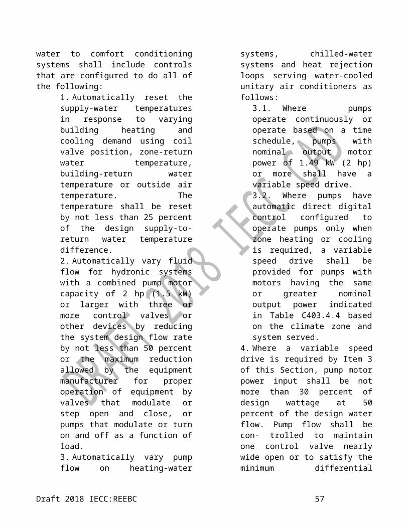
current motors, or 3-phase motors.8. Condenser fan motors that are less than 0.746 kW (1 hp) shall use electronically commutated motors, permanent split capacitor-type motors or 3-phase motors.9. Where antisweat heaters without antisweat heater controls are provided, they shall have a total door rail, glass and frame heater power draw of not more than 76 W/m² (7.1 W/ft²) of door opening for walk-in freezers and 32 W/m² (3.0 W/ft²) of door opening for walk-in coolers.10. Where antisweat heater controls are provided, they shall reduce the energy use of the antisweat heater as a function of the relative humidity in the air outside the door or to the condensation on the inner glass pane.11. Lights in walk-in coolers, walk-in freezers, refrigerated warehouse coolers and refrigerated ware- house freezers shall either use light sources with an efficacy of not less than 40 lumens per watt, including ballast losses, or shall use light sources with an efficacy of not less than 40 lumens per watt, including ballast losses, in conjunction with a device that turns off the lights within 15 minutes when the space is not occupied.
TABLE C403.10.1(1)MINIMUM EFFICIENCY REQUIREMENTS:
COMMERCIAL REFRIGERATION
2018 IECC shall apply.
TABLE C403.10.1(2)MINIMUM EFFICIENCY REQUIREMENTS:
COMMERCIAL REFRIGERATORS AND FREEZERS
2018 IECC shall apply.
TABLE C403.10.1(2)—continuedINIMUM EFFICIENCY REQUIREMENTS:
COMMERCIAL REFRIGERATORS AND FREEZERS
2018 IECC shall apply.
C403.10.2 Walk-in coolers and walk-in freezers (Mandatory).
Site- assembled or site-constructed walk-in coolers and walk-in freezers shall comply with the following:
1. Automatic door closers shall be provided that fully close walk-in doors that have been closed to within 25 mm (1 inch) of full closure.
Exception: Closers are not required for doors more than 1143 mm (45 inches) in width or more than 2134 mm (7 feet) in height.
2. Doorways shall be provided with strip doors, curtains, spring-hinged doors or other method of minimizing infiltration when the doors are open.3. Walls shall be provided with insulation having a thermal resistance of not less than R-4 m²·K/W (R-25 h·ft²·°F/Btu), ceilings shall be provided with insulation having a thermal resistance of not less than R-4 m²·K/W (R-25 h·ft²·°F/Btu) and doors of walk- in coolers and walk-in freezers shall be provided with insulation having a thermal resistance of not less than R-6 m²·K/W (R-25 h·ft²·°F/Btu).
Exception: Insulation is not required for glazed portions of doors or at structural members associated with the walls, ceiling or door frame.
4. The floor of walk-in freezers shall be provided with insulation having a thermal resistance of not less than R-5 m²·K/W (R-28 h·ft²·°F/Btu).5. Transparent reach-in doors for and windows in opaque walk-in freezer doors shall be provided with triple-pane
Draft 2018 IECC:REEBC 59

glass having the interstitial spaces filled with inert gas or provided with heat-reflective treated glass.6. Transparent reach-in doors for and windows in opaque walk-in cooler doors shall be double-pane heat-reflective treated glass having the interstitial space gas filled.7. Evaporator fan motors that are less than 0.746 kW (1 hp) and less than 460 volts shall be electronically commutated motors or 3-phase motors.8. Condenser fan motors that are less than 0.746 kW (1 hp) in capacity shall be of the electronically commutated or permanent split capacitor- type or shall be 3-phase motors.
Exception: Fan motors in walk-in coolers and walk-in freezers combined in a single enclosure greater than 279 m² (3,000 square feet) in floor area are exempt.
9. Antisweat heaters that are not provided with anti- sweat heater controls shall have a total door rail, glass and frame heater power draw not greater than 76 W/m² (7.1 W/ft²) of door opening for walk-in freezers, and not greater than 32 W/m² (3.0 W/ft²) of door opening for walk-in coolers.10. Antisweat heater controls shall be configured to reduce the energy use of the antisweat heater as a function of the relative humidity in the air outside the door or to the condensation on the inner glass pane.11. Light sources shall have an efficacy of not less than 40 lumens per Watt, including any ballast losses, or shall be provided with a device that automatically turns off the lights within 15 minutes of when the walk-in cooler or walk-in freezer was last occupied.
C403.10.2.1 Performance standards (Mandatory).
Walk-in coolers and walk-in freezers shall meet the requirements of Tables C403.10.2.1(1), C403.10.2.1(2) and C403.2.10.2.1(3).
C403.10.3 Refrigerated display cases. 2018 IECC shall apply.
C403.10.4 Refrigeration systems. 2018 IECC shall apply.
C403.10.4.1 Condensers serving refrigeration systems. Fan-powered condensers shall comply with the following:
1. The design saturated condensing temperatures for air-cooled condensers shall not exceed the design dry-bulb temperature plus 5.6°C (10°F) for low-temperature refrigeration systems, and the design dry- bulb temperature plus 8°C (15°F) for medium temperature refrigeration systems where the saturated condensing temperature for blend refrigerants shall be determined using the average of liquid and vapor temperatures as converted from the condenser drain pressure.2. Condenser fan motors that are less than 0.75 kW (1 hp) shall use electronically commutated motors, permanent split-capacitor-type motors or 3-phase motors.3. Condenser fans for air-cooled condensers, evaporatively cooled condensers, air- or water-cooled fluid coolers or cooling towers shall reduce fan motor demand to not more than 30 percent of design watt- age at 50 percent of design air volume, and incorporate one of the following continuous variable speed fan control approaches:
Draft 2018 IECC:REEBC 60

3.1. Refrigeration system condenser control for air-cooled condensers shall use variable setpoint control logic to reset the condensing temperature setpoint in response to ambient dry-bulb temperature.3.2. Refrigeration system condenser control for evaporatively cooled condensers shall use variable setpoint control logic to reset the condensing temperature setpoint in response to ambient wet-bulb temperature.
4. Multiple fan condensers shall be controlled in unison.5. The minimum condensing temperature setpoint shall be not greater than 21˚C (70˚F).
C403.10.4.2 Compressor systems. Refrigeration compressor systems shall comply with the following:
1. Compressors and multiple-compressor system suction groups shall include control systems that use floating suction pressure control logic to reset the target suction pressure temperature based on the temperature requirements of the attached refrigeration display cases or walk-ins.
Exception: Controls are not required for the following:
1. Single-compressor systems that do not have variable capacity capability.2. Suction groups that have a design saturated suction temperature of -1.1˚C (30˚F) or higher, suction groups that comprise the high stage of a two-stage or cascade
system, or suction groups that primarily serve chillers for secondary cooling fluids.
2. Liquid subcooling shall be provided for all low-temperature compressor systems with a design cooling capacity equal to or greater than 29.3 kW (100,000 Btu/h) with a design-saturated suction temperature of -23˚C (-10˚F) or lower. The sub-cooled liquid temperature shall be controlled at a maximum temperature setpoint of 10˚C (50˚F) at the exit of the subcooler using either compressor economizer (interstage) ports or a separate compressor suction group operating at a saturated suction temperature of-7.8˚C (18˚F) or higher.
2.1. Insulation for liquid lines with a fluid operating temperature less than 15.6˚C (60˚F) shall comply with Table C403.2.10.
3. Compressors that incorporate internal or external crankcase heaters shall provide a means to cycle the heaters off during compressor operation.
C403.11 Construction of HVAC system elements.
2018 IECC shall apply.
C403.11.1 Duct and plenum insulation and sealing (Mandatory).
Supply and return air ducts and plenums shall be insulated with not less than R-1.1 (m²·K)/W (R-6 ft²·h·°F/Btu) insulation where located in unconditioned spaces and where located outside the building with not less than R-1.4 (m²·K)/W (R-8 ft²·h·°F/Btu) insulation in Climate Zones 0 through 4. Where located within a building envelope assembly, the duct or
Draft 2018 IECC:REEBC 61

plenum shall be separated from the building exterior or unconditioned or exempt spaces by not less than R-1.4 (m²·K)/W (R-8 ft²·h·°F/Btu) insulation in Climate Zones 0 through 4. Insulation shall be protected from damage, including that due to sunlight, moisture, equipment maintenance and wind, but not limited to the following:
1. Insulation exposed to weather shall be suitable for outdoor service, e.g., protected by aluminium, sheet metal, painted canvas or plastic cover. Cellular foam insulation shall be protected as above or painted with a coating that is water retardant and provides shielding from solar radiation that can cause
degradation of the material.2. Insulation covering cooling ducts
located outside the conditioned space shall include a vapor retardant located outside the insulation (unless the insulation is inherently vapor retardant), all penetrations and joints of which shall be sealed.
Exceptions:1. Where located within equipment.
Ducts, air handlers and filter boxes shall be sealed. Joints and seams shall comply with Section 603.9 of the International Mechanical Code or standards approved by the Authority having Jurisdiction.
TABLE C403.10.2.1(1)WALK-IN COOLER AND FREEZER DISPLAY DOOR EFFICIENCY REQUIREMENTS
2018 IECC shall apply.
TABLE C403.10.2.1(2)WALK-IN COOLER AND FREEZER NONDISPLAY DOOR EFFICIENCY REQUIREMENTS
2018 IECC shall apply.
TABLE C403.10.2.1(3)WALK-IN COOLER AND FREEZER REFRIGERATION SYSTEM EFFICIENCY REQUIREMENTS
CLASS DESCRIPTOR CLASSMINIMUM ANNUAL WALK-IN ENERGY
FACTOR AWEFW (Btu/W-h)
Dedicated condensing, medium temperature, indoor system DC.M.I 1.64 (5.61)Dedicated condensing, medium temperature, indoor system, DC.M.I,
1.64 (5.61)> 2.6 kW (9,000 Btu/h) capacity > 2.6 kW
(9,000 Btu/h)Dedicated condensing, medium temperature, outdoor system DC.M.I 2.23 (7.6)
Dedicated condensing, medium temperature, outdoor system, DC.M.I,2.23 (7.6)
> 2.6 kW (9,000 Btu/h) capacity > 2.6 kW (9,000 Btu/h)
C403.11.2 Duct construction (Mandatory). 2018 IECC shall apply.
C403.11.2.2 Low-pressure duct systems
(Mandatory). Longitudinal and transverse joints, seams and connections of supply and return ducts operating at a static pressure less than or equal
Draft 2018 IECC:REEBC 62

to 2°C (35°F) 498 Pa (2 inches water gauge (w.g.)) shall be securely fastened and sealed with welds, gaskets, mastics (adhesives), mastic-plus-embedded- fabric systems or tapes installed in accordance with the manufacturer’s instructions. Pressure classifications specific to the duct system shall be clearly indicated on the construction documents in accordance with the International Mechanical Code.
Exception: Locking-type longitudinal joints and seams, other than the snap-lock and button-lock types, need not be sealed as specified in this section.
C403.11.2.3 Medium-pressure duct systems.
Ducts and plenums designed to operate at a static pressure greater than 498 Pa (2 inches water gauge (w.g.)) but less than 747 Pa (3 inches w.g) shall be insulated and sealed in accordance with Section C403.11.1. Pressure classifications specific to the duct system shall be clearly indicated on the construction documents in accordance with the International Mechanical Code.
C403.11.2.4 High-pressure duct systems (Mandatory).
Ducts and plenums designed to operate at static pressures greater than 747 Pa (3 inches water gauge) shall be insulated and sealed in accordance with Section C403.11.1. In addition, ducts and plenums shall be leak tested in accordance with the SMACNA HVAC Air Duct Leakage Test Manual and shown to have a rate of air leakage (CL) less than or equal to 4.0 as determined in accordance with Equation 4-8.
CL = F/P0.65Equation 4-8
where:F = The measured leakage rate in cfm per
100 square feet of duct surface.P = The static pressure of the test.
Documentation shall be furnished by the designer demonstrating that representative sections totalling at least 25 percent of the duct area have been tested and that all tested sections comply with the requirements of this section.
C403.11.3 Piping insulation (Mandatory). Piping serving as part of a heating or cooling system shall be thermally insulated in accordance with Table C403.11.3 and when piping and equipment operate at temperatures lower than the ambient air, the pipe system insulation shall include a vapor retardant located outside the insulation (unless the insulation is inherently vapor retardant), and all penetrations and joints of which shall be sealed.
Exceptions:1. Factory-installed piping within
HVAC equipment tested and rated in accordance with a test procedure referenced by this code.
2. Factory-installed piping within room fan-coils and unit ventilators tested and rated according to AHRI 440 (except that the sampling and variation provisions of Section 6.5 shall not apply) and AHRI 840, respectively.
3. Piping that conveys fluids that have a design operating temperature range between 15°C (60°F) and 41°C (105°F).
4. Piping that conveys fluids that have not been heated or cooled through the use of fossil fuels or electric power.
5. Strainers, control valves, and balancing valves associated with piping 25 mm (1 inch) or less in diameter.
Draft 2018 IECC:REEBC 63

6. Direct buried piping that conveys fluids at or below 15°C (60°F).
C403.11.3.1 Protection of piping insulation (Mandatory).
Piping insulation exposed to the weather shall be protected from damage, including that caused by sunlight, moisture, equipment maintenance and wind, and shall provide shielding from solar radiation that can cause degradation of the material. Adhesive tape shall not be permitted.
C403.12 Mechanical systems located outside of the building thermal envelope (Mandatory).2018 IECC shall apply.
C403.12.1 Heating outside a building.Omitted section
C403.12.2 Snow-and ice-melt system controls.
Omit section
C403.12.3 Freeze protection system controls.
Omit section
TABLE C403.11.3c
MINIMUM PIPE INSULATION THICKNESS mm (inches)a
FLUID OPERATING TEMPERATURE RANGE
AND USAGE ° C
INSULATION CONDUCTIVITY NOMINAL PIPE OR TUBE SIZE mm (inches)
Conductivity W/(m · K)b
Mean Rating Temperature,
°C<25 (1) 25 (1) to
<40 (1½)40 (1½) to <100 (4)
100 (4) to <200 (8) ≤200 (8)
> 177 0.046 – 0.049 121 115 125 125 125 125122 – 177 0.042 – 0.046 93 80 100 115 115 11594 – 121 0.039 – 0.043 66 65 65 80 80 8061 – 93 0.036 – 0.042 52 40 50 50 50 5041 – 60 0.032 – 0.040 38 25 25 40 40 404 – 16 0.030 – 0.039 24 13 13 25 25 25
< 4 0.029 – 0.037 10 0.5 13 25 25 38
For IP: 1 mm = 0.04 in, °F = (°C)·1.8 + 32.1. For piping smaller than 38 mm (1½ inches) and located in partitions within conditioned spaces, reduction of these thicknesses by 25.4 mm
(1 inch) shall be permitted (before thickness adjustment required in footnote b) but not to a thickness less than 25.4 mm (1 inch).For insulation outside the stated conductivity range, the minimum thickness (T) shall be determined as follows:
T = r{(1 + t/r)K/k – 1} where:T = minimum insulation thickness,r = actual outside radius of pipe,t = insulation thickness listed in the table for applicable fluid temperature and pipe size,K = conductivity of alternate material at mean rating temperature indicated for the applicable fluid temperature W/( m · K ) and
k = the upper value of the conductivity range listed in the table for the applicable fluid temperature.For direct-buried heating and hot water system piping, reduction of these thicknesses by 11/ inches (38 mm) shall be permitted (before thickness adjustment required in footnote b but not to thicknesses less than 1 inch (25 mm).
Draft 2018 IECC:REEBC 64

TABLE C403.2.3(1)MINIMUM EFFICIENCY REQUIREMENTS:
ELECTRICALLY OPERATED UNITARY AIR CONDITIONERS AND CONDENSING UNITSEQUIPMENT TYPE SIZE CATEGORY HEATING SECTION
TYPESUBCATEGORY
OR RATING CONDITION
MINIMUM EFFICIENCY TEST
PROCEDUREa
Air conditioners, air cooled
<19 kWb All Split system 3.81 SCOPC AHRI 210/240Single package 4.10 SCOPC
Through the wall,air cooled
≤9 kWb All Split system 3.51 SCOPC AHRI 210/240 Single package 3.51 SCOPC
Small duct, high velocity, air cooled
≤19 kWb All Split system 2.93 SCOPC AHRI 210/240
Air conditioners, air cooled
≥19 kW and <40 kW
Electric resistance (or none)
Split system and single package
3.28 COPC3.78 ICOPC
AHRI 340/360
All other 3.22 COPC3.76 ICOPC
≥40 kW and<70 kW
Electric resistance(or none)
3.22 COPC3.75 ICOPC
All other 3.16 COPC3.72 ICOPC
≥70 kW and<223 kW
Electric resistance(or none)
2.93 COPC3.40 ICOPC
All other 2.87 COPC3.34 ICOPC
≥223 kW Electric resistance(or none)
2.84 COPC3.28 ICOPC
All other 2.78 COPC3.22 ICOPC
Air conditioners, water cooled
<19 kW All
Split system and single package
3.54 COPC3.60 ICOPC
AHRI 210/240
≥19 kW and<40 kW
Electric resistance(or none)
3.54 COPC4.07 ICOPC
AHRI 340/360
All other 3.48 COPC4.02 ICOPC
≥40 kW and<70 kW
Electric resistance(or none)
3.66 COPC4.07 ICOPC
All other 3.60 COPC4.02 ICOPC
≥70 kW and<223 kW
Electric resistance(or none)
3.63 COPC3.99 ICOPC
All other 3.57 COPC3.93 ICOPC
≥223 kW Electric resistance(or none)
3.57 COPC3.96 ICOPC
All other 3.51 COPC3.90 ICOPC
(continued)
Draft 2018 IECC:REEBC 65

TABLE C403.2.3(1)—continuedMINIMUM EFFICIENCY REQUIREMENTS:
ELECTRICALLY OPERATED UNITARY AIR CONDITIONERS AND CONDENSING UNITS
EQUIPMENT TYPE SIZE CATEGORY
HEATING SECTION TYPE
SUB-CATEGORY OR RATING CONDITION
MINIMUM EFFICIENCY
TEST PROCEDUREa
Air conditioners, evaporatively cooled
<19 kWb All Split System and Single Package
3.54 COPC AHRI 210/2403.60 ICOPC
≥19 kW and <40 kW
Electric Resistance (or None)
Split System and Single Package
3.54 COPC
AHRI 340/360
3.60 ICOPC
All other Split System and Single Package
3.48 COPC3.54 ICOPC
≥40 kW and <70 kW
Electric Resistance (or None)
Split System and Single Package
3.51 COPC3.57 ICOPC
All other Split System and Single Package
3.46 COPC3.51 ICOPC
≥70 kW and <223 kW
Electric Resistance (or None)
Split System and Single Package
3.48 COPC3.54 ICOPC
All other Split System and Single Package
3.43 COPC3.48 ICOPC
≥223 kW
Electric Resistance (or None)
Split System and Single Package
3.43 COPC3.48 ICOPC
All other Split System and Single Package
3.37 COPC3.43 ICOPC
Condensing units, air cooled ≥40 kW
3.07 COPC
AHRI 365
3.46 ICOPCCondensing units, water
cooled ≥40 kW 3.95 COPC 4.10 ICOPC
Condensing units, evaporatively cooled ≥40 kW
3.95 COPC 4.10 ICOPC
For IP: 1 kW = 3,412 Btu/h.a. Chapter 6 contains a complete specification of the referenced test procedure, including the reference year version of the test procedure.b. Single-phase, air-cooled air conditioners less than 19 kW (65,000 Btu/h) are regulated by NAECA. SEER values are those set by NAECA.
Draft 2018 IECC:REEBC 66

TABLE C403.2.3(2)MINIMUM EFFICIENCY REQUIREMENTS: ELECTRICALLY OPERATED UNITARY AND APPLIED HEAT PUMPS
EQUIPMENT TYPE SIZE CATEGORY
HEATING SECTION TYPE
SUBCATEGORY OR RATING CONDITION
MINIMUM EFFICIENCY
TEST PROCEDUREa
Air cooled (cooling mode)
<19 kWbAll
Split system 4.10 SCOPC
AHRI 210/240
Single package 4.10 SCOPCThrough the wall,
air cooled ≤9 kWb AllSplit system 3.52 SCOPC
Single package 3.52 SCOPCSmall duct, high
velocity, air cooled≤19 kWb
All Split System 2.93 SCOPC
Air cooled (cooling mode)
≥19 kW and <40 kW
Electric Resistance (or None)
Split System and Single Package
3.22 COPC
AHRI340/360
3.57 ICOPC
All other Split System and Single Package
3.17 COPC3.52 ICOPC
≥40 kW and<70 kW
Electric Resistance (or None)
Split System and Single Package
3.11 COPC3.40 ICOPC
All other Split System and Single Package
3.05 COPC3.34 ICOPC
≥70 kW
Electric Resistance (or None)
Split System and Single Package
2.78 COPC3.11 ICOPC
All other Split System and Single Package
2.72 COPC3.05 ICOPC
Water to air, water loop (cooling mode)
<5 kW All 30°C entering water 3.57 COPC
ISO 13256-1
≥5 kW and <19 kW All 30°C entering water 3.81 COPC
≥19 kW and <40 kW All 30°C entering water 3.81 COPC
Water to air, groundwater (cooling
mode)<40 kW All 15°C entering water 5.27 COPC
Brine to air, ground loop (cooling mode) <40 kW All 25°C entering water 4.13 COPC
Water to water, water loop (cooling mode) <40 kW All 30°C entering water 3.10 COPC
ISO 13256-2Water to water,
groundwater (cooling mode)
<40 kW All 15°C entering water 4.77 COPC
Brine to water, ground loop (cooling mode) <40 kW All 25°C entering water 3.55 COPC
(continued)
Draft 2018 IECC:REEBC 67

TABLE C403.2.3(2)—continued MINIMUM EFFICIENCY REQUIREMENTS:
ELECTRICALLY OPERATED UNITARY AND APPLIED HEAT PUMPS
EQUIPMENT TYPE SIZE CATEGORY
HEATING SECTION
TYPE
SUBCATEGORY OR RATING CONDITION
MINIMUM EFFICIENCY
TEST PROCEDUREa
Air cooled (heating mode) <19 kWb
— Split system 2.26 SCOPH
AHRI 210/240
— Single package 2.40 SCOPHThrough-the-wall,
(air cooled, heating mode) ≤9 kWb— Split system 3.34 SCOPH— Single package 2.17 SCOPH
Small-duct high velocity (air cooled, heating mode) <19 kWb — Split system 2.17 SCOPH
Air cooled (heating mode)
≥40 kW and
<70 kW
— 8.3°C db/6.1°C wb outdoor air 3.3 COPH
AHRI 340/360
— –8.3°C db/–9.4°C wb outdoor air 2.25 COPH
≥70 kW— 8.3°C db/6.1°C wb
outdoor air 3.2 COPH
— 8.3°C db/–9.4°C wb outdoor air 2.05 COPH
Water to Air: Water Loop (heating mode) <40 kW — 20°C entering
water 4.3 COPH
ISO 13256-1Water to Air: Ground Water (heating mode) <40 kW — 10°C entering
water 3.7 COPH
Brine to Air: Ground Loop (heating mode) <40 kW — 0°C entering fluid 3.2 COPH
Water to Water: Water Loop (heating mode) <40 kW — 20°C entering
water 3.7 COPH
ISO 13256-2Water to Water: Ground Water (heating mode) <40 kW — 10°C entering
water 3.1 COPH
Brine to Water: Ground Loop (heating mode) <40 kW — 0°C entering fluid 2.5 COPH
For IP: 1 kW = 3,412 Btu/hr.a. Chapter 6 contains a complete specification of the referenced test procedure, including the reference year version of the test procedure.b. Single-phase, air-cooled air conditioners less than 19 kW (65,000 Btu/h) are regulated by NAECA. SEER values are those set by NAECA.
Draft 2018 IECC:REEBC 68

TABLE C403.2.3(3)MINIMUM EFFICIENCY REQUIREMENTS:
ELECTRICALLY OPERATED PACKAGED TERMINAL AIR CONDITIONERS,PACKAGED TERMINAL HEAT PUMPS, SINGLE-PACKAGE VERTICAL AIR CONDITIONERS,
SINGLE VERTICAL HEAT PUMPS, ROOM AIR CONDITIONERS AND ROOM AIR-CONDITIONER HEAT PUMPS
EQUIPMENT TYPE SIZE CATEGORY SUBCATEGORY OR RATING CONDITION
MINIMUM EFFICIENCY
TEST PROCEDUREa
PTAC (cooling mode) new construction All capacities 35.0°C db outdoor air 4.10 – (0.300 ×
Cap/1000) COPC
AHRI 310/380
PTAC (cooling mode) replacementsb All capacities 35.0°C db outdoor air 3.19 – (0.213 ×
Cap/1000) COPCPTHP (cooling mode)
new construction All capacities 35.0°C db outdoor air 4.10 – (0.300 × Cap/1000) COPC
PTHP (cooling mode) replacementsb All capacities 35.0°C db outdoor air 3.16 – (0.213 ×
Cap/1000) COPCPTHP (heating mode)
new construction All capacities — 3.7 – (0.052 × Cap/1000) COPH
PTHP (heating mode) replacementsb All capacities — 2.9 – (0.026 ×
Cap/1000) COPH
SPVAC (cooling mode)
<19 kW 35.0°C db/23.9°C wb outdoor air 2.64 COPC
AHRI 390
≥40 kW and<70 kW 35.0°C db/23.9°C wb outdoor air 2.61 COPC
≥70 kW 35.0°C db/23.9°C wb outdoor air 2.52 COPC
SPVHP (cooling mode)
<19 kW 35.0°C db/23.9°C wb outdoor air 2.64 COPC≥40 kW and
<70 kW 35.0°C db/23.9°C wb outdoor air 2.61 COPC
≥70 kW 35.0°C db/23.9°C wb outdoor air 2.52 COPC
SPVHP (heating mode)
<19 kW 8.3°C db/6.1°C wb outdoor air 3.0 COPH≥40 kW and
<70 kW 8.3°C db/6.1°C wb outdoor air 3.0 COPH
≥70 kW 8.3°C db/6.1°C wb outdoor air 2.9 COPH
Room air conditioners, with louvered sides
<1.8 kW — 2.84 COPC
ANSI/AHAM RAC-1
≥1.8 kW and <2.3 kW — 2.84 COPC
≥2.3 kW and <4.1 kW — 2.87 COPC
≥4.1 kW and <5.9 kW — 2.84 COPC
≥5.9 kW — 2.49 COPC
Room air conditioners, without louvered sides
<2.3 kW — 2.64 COPC≥2.3 kW
and <5.9 kW — 2.49 COPC
≥5.9 kW — 2.49 COPCRoom air conditioners,
with louvered sides<5.9 kW — 2.64 COPC≥5.9 kW — 2.49 COPC
Room air conditioners, without louvered sides
<5.9 kW — 2.49 COPC
≥5.9 kW — 2.34 COPC
Draft 2018 IECC:REEBC 69

(continued)
TABLE C403.2.3(3)—continued MINIMUM EFFICIENCY REQUIREMENTS:
ELECTRICALLY OPERATED PACKAGED TERMINAL AIR CONDITIONERS, PACKAGED TERMINAL HEAT PUMPS, SINGLE-PACKAGE VERTICAL AIR CONDITIONERS,
SINGLE VERTICAL HEAT PUMPS, ROOM AIR CONDITIONERS AND ROOM AIR-CONDITIONER HEAT PUMPS
EQUIPMENT TYPE SIZE CATEGORY
SUBCATEGORY OR RATING CONDITION
MINIMUM EFFICIENCY
TEST PROCEDUREa
Room air conditioner casement only All capacities — 2.55 COPCANSI/
AHAM RAC-1Room air conditioner casement-slider All capacities — 2.78 COPC
For IP: °F = 1.8 · °C + 32, kW = (Btu/h) · 3,412, EER [Btu/W] = COP [W/W] · 3.412“Cap” = The rated cooling capacity of the project in Btu/h. Where the unit’s capacity is less than 2 kW (7000 Btu/h), use 2 kW (7000 Btu/h) in the calculation. Where the unit’s capacity is greater than 4 kW (15,000 Btu/h), use 4 kW (15,000 Btu/h) in the calculations.a. Chapter 6 contains a complete specification of the referenced test procedure, including the referenced year version of the test procedure.
b. Replacement unit shall be factory labeled as follows: “MANUFACTURED FOR REPLACEMENT APPLICATIONS ONLY: NOT TO BE INSTALLED IN NEW CONSTRUCTION PROJECTS.” Replacement efficiencies apply only to units with existing sleeves less than 406 mm (16 inches) in height and less than 1067 mm (42 inches) in width.
TABLE 403.2.3(4)WARM-AIR FURNACES AND COMBINATION WARM-AIR FURNACES/AIR-CONDITIONING UNITS,
WARM-AIR DUCT FURNACES AND UNIT HEATERS, MINIMUM EFFICIENCY REQUIREMENTS
EQUIPMENT TYPE SIZE CATEGORY (INPUT)
SUBCATEGORY OR RATING CONDITION
MINIMUM EFFICIENCYd, e TEST PROCEDUREa
Warm-air furnaces, gas fired
< 66 kW — 78% AFUE or 80%Et
cDOE 10 CFR Part
430 or ANSI Z21.47≥ 66 kW Maximum capacityc 80%Et
f ANSI Z21.47
Warm-air furnaces, oil fired
< 66 kW — 78% AFUE or DOE 10 CFR Part 430 or
≥ 66 kW Maximum capacityb 81%Etg UL 727
Warm-air duct furnaces, gas fired All capacities Maximum capacityb 80%Ec ANSI Z83.8
Warm-air unit heaters, gas fired All capacities Maximum capacityb 80%Ec ANSI Z83.8
Warm-air unit heaters, oil fired All capacities Maximum capacityb 80%Ec UL 731
For IP: 1 kW = 3,412 Btu/h.a. Chapter 6 contains a complete specification of the referenced test procedure, including the referenced year version of the test procedure.b. Minimum and maximum ratings as provided for and allowed by the unit’s controls.c. Combination units not covered by the National Appliance Energy Conservation Act of 1987 (NAECA) (3-phase power or cooling capacity greater than or equal to 19 kW [65,000 Btu/h]) shall comply with either rating.d. Et = Thermal efficiency. See test procedure for detailed discussion.e. Ec = Combustion efficiency (100% less flue losses). See test procedure for detailed discussion.f. Ec = Combustion efficiency. Units shall also include an IID, have jackets not exceeding 0.75 percent of the input rating, and have either power venting or a flue damper. A vent damper is an acceptable alternative to a flue damper for those furnaces where combustion air is drawn from the
Draft 2018 IECC:REEBC 70

conditioned space.g. Et = Thermal efficiency. Units shall also include an IID, have jacket losses not exceeding 0.75 percent of the input rating, and have either power venting or a flue damper. A vent damper is an acceptable alternative to a flue damper for those furnaces where combustion air is drawn from the conditioned space.
TABLE C403.2.3(5)MINIMUM EFFICIENCY REQUIREMENTS: GAS- AND OIL-FIRED BOILERS
EQUIPMENT TYPE SUBCATEGORY OR RATING CONDITION
SIZE CATEGORY (INPUT)
MINIMUM EFFICIENCYd, e
TEST PROCEDURE
Boilers, hot water
Gas-fired
< 87 kW 80% AFUE 10 CFR Part 430≥ 87 kW and
≤ 733 kWb80% Et
10 CFR Part 431> 733 kWa 82% Ec
Oil-firedc
< 87 kW 80% AFUE 10 CFR Part 430≥ 87 kW and
≤ 733 kWb82% Et
10 CFR Part 431> 733 kWa 84% Ec
Boilers, steam
Gas-fired < 87 kW 75% AFUE 10 CFR Part 430
Gas-fired- all, except natural draft
≥ 87 kW and ≤ 733 kWb
79% Et
10 CFR Part 431> 733 kWa 79% Et
Gas-fired, natural draft≥ 87 kW and
≤ 733 kWb 77% Et
> 733 kWa 77% Et
Oil-firedc
< 87 kW 80% AFUE 10 CFR Part 430≥ 87 kW and
≤ 733 kWb 81% Et 10 CFR Part 431> 733 kWa 81% Et
For IP: 1 kW = 3,412 Btu/h.a. Chapter 6 contains a complete specification of the referenced test procedure, including the referenced year version of the test procedure.b. Minimum and maximum ratings as provided for and allowed by the unit’s controls.
c. Combination units not covered by the National Appliance Energy Conservation Act of 1987 (NAECA) (3-phase power or cooling capacity greater than or equal to 19 kW [65,000 Btu/h]) shall comply with either rating.d. Et = Thermal efficiency. See test procedure for detailed discussion.e. Ec = Combustion efficiency (100% less flue losses). See test procedure for detailed discussion.
f. Ec = Combustion efficiency. Units shall also include an IID, have jackets not exceeding 0.75 percent of the input rating, and have either power venting or a flue damper. A vent damper is an acceptable alternative to a flue damper for those furnaces where combustion air is drawn from the conditioned space.g. Et = Thermal efficiency. Units shall also include an IID, have jacket losses not exceeding 0.75 percent of the input rating, and have either power venting or a flue damper. A vent damper is an acceptable alternative to a flue damper for those furnaces where combustion air is drawn from the conditioned space.
TABLE C403.2.3(6)MINIMUM EFFICIENCY REQUIREMENTS: CONDENSING UNITS, ELECTRICALLY OPERATED
EQUIPMENT TYPE SIZE CATEGORY
MINIMUM EFFICIENCYb
TEST PROCEDUREa
Condensing units, air cooled ≥ 40 kW10.1 EER
AHRI 36511.2 IPLV
Draft 2018 IECC:REEBC 71
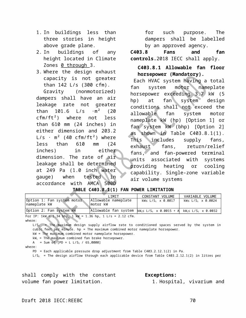
Condensing units, water or evaporatively cooled ≥ 40 kW13.1 EER13.1 IPLV
For IP: 1 kW = 3,412 Btu/h.a. Chapter 6 contains a complete specification of the referenced test procedure, including the referenced year version of the test procedure.b. IPLVs are only applicable to equipment with capacity modulation.
TABLE C403.2.3(7)WATER CHILLING PACKAGES – EFFICIENCY REQUIREMENTSa, b, d
EQUIPMENT TYPE SIZE CATEGORY UNITS Path A Path B TEST PROCEDUREc
Air-cooled chillers<528 kW
COP (W/W)
≥2.985 FL ≥2.866 FL
AHRI 551/591
≥4.048 IPLV.SI ≥4.669 IPLV.SI
≥528 kW≥2.985 FL ≥2.866 FL
≥4.137 IPLV.SI ≥4.758 IPLV.SI
Air cooled without condenser, electrically operated
All capacities COP (W/W)
Air-cooled chillers without condenser shall be rated with matching condensers
and complying with air-cooled chiller efficiency requirements.
Water cooled, electrically
operated positive displacement
<264 Kw
COP (W/W)
≥4.694 FL ≥4.513 FL≥5.867 IPLV.SI ≥7.041 IPLV.SI
≥264 Kw and <528 kW≥4.889 FL ≥4.694 FL
≥6.286 IPLV.SI ≥7.184 IPLV.SI≥528 KW and <1055
kW≥5.334 FL ≥5.177 FL
≥6.519 IPLV.SI ≥8.001 IPLV.SI≥1055 KW and <2110
kW≥5.771 FL ≥5.633 FL
≥6.770 IPLV.SI ≥8.586 IPLV.SI
≥2110 KW ≥6.286 FL ≥6.018 FL≥7.041 IPLV.SI ≥9.264 IPLV.SI
Water cooled, electrically operated
centrifugal
≥528 KW and <1055 kW
COP (W/W)
≥5.771 FL ≥5.065 FL≥6.401 IPLV.SI ≥8.001 IPLV.SI
≥528 KW and <1055 kW
≥5.771 FL ≥5.544 FL≥6.401 IPLV.SI ≥8.001 IPLV.SI
≥528 KW and <1055 kW
≥6.286 FL ≥6.018 FL≥6.770 IPLV.SI ≥8.586 IPLV.SI
≥528 KW and <1055 kW
≥6.286 FL ≥6.018 FL≥7.041 IPLV.SI ≥9.264 IPLV.SI
≥528 KW and <1055 kW
≥6.286 FL ≥6.018 FL≥7.041 IPLV.SI ≥9.264 IPLV.SI
Air cooled, absorption, single
effectAll capacities COP ≥0.600 FL NAc
AHRI 560Water cooled absorption, single
effectAll capacities COP ≥0.700 FL NAc
Absorption, double All capacities COP ≥1.000 FL NAc
Draft 2018 IECC:REEBC 72

effect, indirect fired ≥1.050 IPLV.SIAbsorption double effect direct fired All capacities COP
≥1.000 FLNAc
≥1.050 IPLV.SIFor IP: °F = 1.8 · °C + 32, kW/ton = 12/(COP · 3.412), Ton = 3.517 · kW, EER [Btu/W] = COP [W/W] / 3.412a. The requirements for centrifugal chiller shall be adjusted for nonstandard rating conditions in accordance with Section C403.2.3.1 and are only applicable for the range of conditions listed in Section C403.2.3.1. The requirements for air-cooled, water-cooled positive displacement and absorption chillers are at standard rating conditions defined in the reference test procedure.b. Both the full-load and IPLV requirements shall be met or exceeded to comply with this standard. Where there is a Path B, compliance can be with either Path A or Path B for any application.c. NA means the requirements are not applicable for Path B and only Path A can be used for compliance.d. FL represents the full-load performance requirements and IPLV the part-load performance requirements.
TABLE C403.2.3(8)MINIMUM EFFICIENCY REQUIREMENTS: HEAT REJECTION EQUIPMENT
EQUIPMENT TYPEa
TOTAL SYSTEM HEAT REJECTION
CAPACITY AT RATED
CONDITIONS
SUBCATEGORY OR RATING CONDITIONi
PERFORMANCE REQUIRED b, c,
d, g, h
TEST PROCEDURE e, f
Propeller or axial fan open-circuit cooling towers
All35.0°C entering water 29.4°C leaving water 23.9°C entering wb
≥3.40 L/s·kW CTI ATC-105 and CTI STD-201 RS
Centrifugal fan open-circuit cooling
towersAll
35.0°C entering water≥1.7 L/s·kW CTI ATC-105 and
CTI STD-201 RS29.4°C leaving water23.9°C entering wb
Propeller or axial fan closed-circuit
cooling towersAll
38.9°C entering water≥1.36 L/s·kW CTI ATC-105S and
CTI STD-201 RS32.2°C leaving water23.9°C entering wb
Centrifugal closed-circuit cooling
towersAll
38.9°C entering water≥0.59 L/s·kW CTI ATC-105S and
CTI STD-201 RS32.2°C leaving water23.9°C entering wb
Propeller or axial fan evaporative
condensersAll
Ammonia test fluid
≥52.6 COPC CTI ATC-10660°C entering gas temperature35.7°C condensing temperature
23.9°C entering wb
Propeller or axial fan evaporative
condensersAll
R-507A test fluid
≥61.6 COPC CTI ATC-10673.9°C entering gas temperature40.6°C condensing temperature
23.9°F entering wb
Centrifugal fan evaporative condensers
All
Ammonia test fluid
≥43.2 COPC CTI ATC-10660°C entering gas temperature35.7°C condensing temperature
23.9°C entering wb
Centrifugal fan evaporative condensers
All
R-507A test fluid
≥53.0 COPC CTI ATC-10673.9°C entering gas temperature40.6°C condensing temperature
23.9°F entering wbAir cooled
condensersAll 52°C condensing temperature
88°C entering gas temperature≥69 COPC AHRI 460
8°C subcooling
Draft 2018 IECC:REEBC 73

35°C entering dbFor IP: °F = 1.8 · °C + 32, gpm/hp = (L/(s · kW))·(11.83), Btu/(h · hp) = COP·2550.7, db = dry bulb temperature, °C, wb = wet bulb temperature, °C.a. The efficiencies and test procedures for both open- and closed-circuit cooling towers are not applicable to hybrid cooling towers that contain a combination of wet and dry heat exchange sections.b. For purposes of this table, open circuit cooling tower performance is defined as the water flow rating of the tower at the thermal rating condition listed in Table 403.2.3(8) divided by the fan nameplate-rated motor power.c. For purposes of this table, closed-circuit cooling tower performance is defined as the water flow rating of the tower at the thermal rating condition listed in Table 403.2.3(8) divided by the sum of the fan nameplate-rated motor power and the spray pump nameplate-rated motor power.d. For purposes of this table, air-cooled condenser performance is defined as the heat rejected from the refrigerant divided by the fan nameplate-rated motor power.e. Chapter 6 contains a complete specification of the referenced test procedure, including the referenced year version of the test procedure. The certification requirements do not apply to field-erected cooling towers.f. Where a certification program exists for a covered product and it includes provisions for verification and challenge of equipment efficiency ratings, then the product shall be listed in the certification program; or, where a certification program exists for a covered product, and it includes provisions for verification and challenge of equipment efficiency ratings, but the product is not listed in the existing certification program, the ratings shall be verified by an independent laboratory test report.g. Cooling towers shall comply with the minimum efficiency listed in the table for that specific type of tower with the capacity effect of any project-specific accessories and/or options included in the capacity of the cooling tower.h. For purposes of this table, evaporative condenser performance is defined as the heat rejected at the specified rating condition in the table divided by the sum of the fan motor nameplate power and the integral spray pump nameplate power.i. Requirements for evaporative condensers are listed with ammonia (R-717) and R-507A as test fluids in the table. Evaporative condensers intended for use with halocarbon refrigerants other than R-507A shall meet the minimum efficiency requirements listed in this table with R-507A as the test fluid.
TABLE C403.2.3(9)MINIMUM EFFICIENCY AIR CONDITIONERS AND CONDENSING UNITS SERVING COMPUTER ROOMS
EQUIPMENT TYPE NET SENSIBLE COOLING CAPACITYa
MINIMUM SCOP-127b EFFICIENCY DOWNFLOW UNITS / UPFLOW
UNITSTEST PROCEDURE
Air conditioners, air cooled<19 Kw 2.20 / 2.09
ANSI/ASHRAE 127
≥19 kW and < 70 kW 2.10 / 1.99≥70 kW 1.90 / 1.79
Air conditioners, water cooled<19 kW 2.60 / 2.49
≥19 kW and < 70 kW 2.50 / 2.39≥70 kW 2.40 /2.29
Air conditioners, water cooled with fluid economizer
<19 kW 2.55 /2.44≥19 kW and < 70 kW 2.45 / 2.34
≥70 kW 2.35 / 2.24
Air conditioners, glycol cooled (rated at 40% propylene glycol)
<19 kW 2.50 / 2.39≥19 kW and < 70 kW 2.15 / 2.04
≥70 kW 2.10 / 1.99Air conditioners, glycol cooled
(rated at 40% propylene glycol) with fluid economizer
<19 kW 2.45 / 2.34≥19 kW and < 70 kW 2.10 / 1.99
≥70 kW 2.05 / 1.94For IP: 1 kW = 3,412 Btu/ha. Net sensible cooling capacity: the total gross cooling capacity less the latent cooling less the energy to the air movement system. (Total Gross – latent – Fan Power).
b. Sensible coefficient of performance (SCOP-127): a ratio calculated by dividing the net sensible cooling capacity in watts by the total power input in watts (excluding reheaters and humidifiers) at conditions defined in ASHRAE Standard 127. The net sensible cooling capacity is the gross sensible capacity minus the energy dissipated into the cooled space by the fan system.
Draft 2018 IECC:REEBC 74

TABLE C403.2.3(10)HEAT TRANSFER EQUIPMENT
2018 IECC shall apply.
Draft 2018 IECC:REEBC 75

TABLE C403.2.3(11)MINIMUM EFFICIENCY REQUIREMENTS:
VARIABLE REFRIGERANT FLOW MULTI-SPLIT AIR CONDITIONERS AND HEAT PUMPS
EQUIPMENT TYPE SIZE CATEGORY HEATING TYPE MINIMUM EFFICIENCY
TEST PROCEDURE
VRF Multi-Split Air Conditioners (Air-cooled)
≤19 kW All 3.81 SCOPc
AHRI 1230
≥19 kW and <40 kWElectric Resistance
(or none) 4.54 ICOP
All other 4.37 ICOP
≥40 kW and<70 kW
Electric Resistance (or none) 4.37 ICOP
All other 4.07 ICOP
≥70 kW and<223 kW
Electric Resistance (or none) 4.07 ICOP
All other 3.52 ICOP
VRF Multi-Split Heat Pumps (Air-cooled)
≤19 kW All 3.81 SCOP
≥19 kW and <40 kWElectric Resistance
(or none) 4.37 ICOP
All other 4.22 ICOP
≥40 kW and<70 kW
Electric Resistance (or none) 4.07 ICOP
All other 4.01 ICOP
≥70 kW and<223 kW
Electric Resistance (or none) 3.72 ICOP
All other 3.52 ICOP
VRF Multi-Split Air Conditioners
(Water-Source)
≤5 kW Without heat recovery 4.69 ICOPWith heat recovery 4.63 ICOP
≥5 kW and <19 kW All 4.69 ICOP
≥19 kW and <40 kW All 4.69 ICOP
≥40 kW and<223 kW
Without heat recovery 4.07 ICOPWith heat recovery 3.46 ICOP
For IP: 1 kW = 3,412 Btu/h, IEER = ICOP · 3.412
Table C403.2.7(1) ENERGY RECOVERY REQUIREMENT
(Ventilation systems operating less than 8,000 hours per year)
CLIMATE ZONE
PERCENT (%) OUTDOOR AIR AT FULL DESIGN AIRFLOW RATE≥10% and <
20%≥20% and <
30%≥30% and <
40%≥40% and <
50%≥50% and <
60%≥60% and <
70%≥70% and <
80%≥80%
DESIGN SUPPLY FAN AIRFLOW RATE 0A, 1A, 2A ≥ 12,271 L/s
(26,000 cfm)≥ 7,551 L/s
(16,000 cfm)≥ 2,596 L/s(5,500 cfm)
≥ 2,124 L/s(4,500 cfm)
≥ 1,652 L/s(3,500 cfm)
≥ 944 L/s(2,000 cfm)
≥ 472 L/s(1,000 cfm)
> 0
0B, 1B, 2B NR NR NR NR ≥ 1,652 L/s(3,500 cfm)
≥ 944 L/s(2,000 cfm)
≥ 472 L/s(1,000 cfm)
> 0
For IP: 1 L/s = 2.119 cfm.
Draft 2018 IECC:REEBC 76

Table C403.2.7(2) ENERGY RECOVERY REQUIREMENT
(Ventilation systems operating not less than 8,000 hours per year)
CLIMATE ZONE
PERCENT (%) OUTDOOR AIR AT FULL DESIGN AIRFLOW RATE≥10% and <
20%≥20% and <
30%≥30% and <
40%≥40% and <
50%≥50% and <
60%≥60% and <
70%≥70% and <
80%≥80%
DESIGN SUPPLY FAN AIRFLOW RATE 0A, 1A, 2A ≥ 1,180 L/s
(2,500 cfm)≥ 944 L/s
(2,000 cfm)≥ 472 L/s
(1,000 cfm)≥ 500 L/s (236 cfm)
> 0 > 0 > 0 > 0
0B, 1B, 2B NR ≥ 8,967 L/s (19,000 cfm)
≥ 4,248 L/s (9,000 cfm)
≥ 2,360 L/s (5,000 cfm)
≥ 1,888 L/s (4,000 cfm)
≥ 1,416 L/s (3,000 cfm)
≥ 472 L/s (1,000 cfm)
> 0
For IP: 1 L/s = 2.119 cfm.
Table C403.3(1)MINIMUM CHILLED-WATER SYSTEM COOLING CAPACITY FOR DETERMINING ECONOMIZER COOLING
REQUIREMENTS
CLIMATE ZONES(COOLING)
TOTAL CHILLED-WATER SYSTEM CAPACITY LESS CAPACITY OF COOLING UNITS WITH AIR ECONOMIZERS
Local Water-cooled Chilled-water Systems
Air-cooled Chilled-water Systems or District Chilled-Water Systems
0A, 1A No economizer requirement No economizer requirement1B, 2A, 2B 281 kW 366 kW
For IP: 1 kW = 3,412 Btu/h.
SECTION C404SERVICE WATER HEATING (MANDATORY)
C404.1 General. 2018 IECC shall apply.C404.2 Service water-heating equipment performance efficiency. 2018 IECC shall apply.
C404.2.1 High input-rated service water-heating systems. Gas-fired water-heating equipment installed in new buildings shall be in compliance with this section. Where a singular piece of water-heating equipment serves the entire building and the input rating of the equipment is 293 kW (1,000,000 Btu/h) or greater, such equipment shall have a thermal efficiency, Et, of not less than 90 percent. Where multiple pieces of water-heating equipment serve the building and the combined input rating of the water-heating equipment is 293 kW (1,000,000 Btu/h) or greater, the
combined input-capacity-weighted-average thermal efficiency, Et, shall be not less than 90 percent.
Exceptions:1. Where not less than 25 percent of the annual service water-heating requirement is provided by on- site renewable energy or site-recovered energy, the minimum thermal efficiency requirements of this section shall not apply.2. The input rating of water heaters installed in individual dwelling units shall not be required to be included in the total input rating of service water- heating equipment for a building.3. The input rating of water heaters with an input rating of not
Draft 2018 IECC:REEBC 77

greater than 29.3 kW (100,000 Btu/h) shall not be required to be included in the total input rating of service water-heating equipment for a building.
C404.3 Heat traps. 2018 IECC shall apply.C404.4 Insulation of piping. Piping from a water heater to the termination of the heated water fixture supply pipe shall be insulated in accordance with Table C403.2.10. On both the inlet and outlet piping of a storage water heater or heated water storage tank, the piping
to a heat trap or the first 2438 mm (8 feet) of piping, whichever is less, shall be insulated. Piping that is heat traced shall be insulated in accordance with Table C403.2.10 or the heat trace manufacturer’s instructions. Tubular pipe insulation shall be installed in accordance with the insulation manufacturer’s instructions. Pipe insulation shall be continuous except where the piping passes through a framing member. The minimum insulation thickness requirements of this section shall not supersede any greater insulation thickness requirements necessary
TABLE C404.2MINIMUM PERFORMANCE OF WATER-HEATING EQUIPMENT
EQUIPMENT TYPE SIZE CATEGORY(input)
SUBCATEGORY OR RATING CONDITION
PERFORMANCE REQUIREDa, b
TEST PROCEDURE
Water heaters, electric
≤12 kWd
Tabletope, ≥ 76 L and ≤ 454 L 0.93 − 0.00035V, EF
DOE 10 CFR Part 430
Resistance 0.960 - 0.0008V, EF
Grid-enabledf > 284 and ≤ 454 L 1.061 - 0.00044V, EF
> 12 kW Resistance (0.3 + 27/Vm), %/h ANSI Z21.10.3≤24 amps and Heat pump > 208 L
and ≤ 454L 2.057 - 0.0003V, EF DOE 10 CFR Part 430≤250 volts
Storage water heaters, gas
≥58.62 kW
≥ 75 L and≤ 208 L 0.675 - 0.0004V, EF
DOE 10 CFR Part 430> 208 L and
≤ 379 L 0.8012 - 0.00021V, EF
> 23 kW and< 310 W/L
80% Et
ANSI Z21.10.3≤45 kW
>45 kW < 310 W/L80% Et
Instantaneous water heaters, gas
>14.66 kW and ≥310 W/L and <7.6 L 0.82 - 0.0005V, EF DOE 10 CFR
Part 430<58.62 kWc
≥58.62 kW ≥310 W/L and <38 L 80% Et
ANSI Z21.10.3≥58.62 kW ≥310 W/L and ≥38 L
80% Et
Storage water heaters, oil≤30.78 kW ≥76 L 0.68 - 0.0005V, EF DOE 10 CFR
Part 430> 30.78 kW <310 W/L
80% Et ANSI Z21.10.3
Instantaneous water heaters, oil
≤61.55 kW ≥310 W/L and <7.6 L 0.59 - 0.0005V, EF DOE 10 CFR Part 430>61.55 kW ≥310 W/L and <38 L 80% Et
ANSI Z21.10.3>61.55 kW ≥310 W/L and ≥38 L
78% Et
Hot water supply boilers, gas and oil
≥58.62 kW and≥310 W/L and <38 L 80% Et
ANSI Z21.10.3
<3663.8 kW
Hot water supply boilers, gas ≥58.62 kW and ≥310 W/L and ≥38 L 80% Et
<3664 kW
Draft 2018 IECC:REEBC 78

Hot water supply boilers, oil≥58.62 kW and
≥310 W/L and ≥38 L78% Et
<3664 kW
Pool heaters, gas and oil All — 82% Et ASHRAE 146
(continued)
TABLE C404.2—continuedMINIMUM PERFORMANCE OF WATER-HEATING EQUIPMENT
EQUIPMENT TYPE SIZE CATEGORY(input)
SUBCATEGORY OR RATING CONDITION
PERFORMANCE REQUIREDa, b
TEST PROCEDURE
Heat pump pool heaters All — 4.0 COP AHRI 1160
Unfired storage tanks All —
Minimum insulation requirement R-2.2 W/(m·K) (R-12.5 (h · ft² · °F)/Btu)
(none)
For IP: °F = [°C · 1.8] + 32, 1 kW = 3,412 Btu/h, 1 L = 0.2642, 1 W/L = 5,076 Btu/gal.
a. Energy factor (EF) and thermal efficiency (Et) are minimum requirements. In the EF equation, V is the rated volume in litres.
b. Standby loss (SL) is the maximum Btu/h based on a nominal 21°C (70°F) temperature difference between stored water and ambient requirements. In the SL equation, Q is the nameplate input rate in Btu/h. In the equations for electric water heaters, V is the rated volume in litres and Vm is the measured volume in litres. In the SL equation for oil and gas water heaters and boilers, V is the rated volume in litres.
c. Instantaneous water heaters with input rates below 59 kW (200,000 Btu/h) shall comply with these requirements where the water heater is designed to heat water to temperatures 82°C (180°F) or higher.d. Electric water heaters with an input rating of 12 kW (40,950 Btu/hr) or less that are designed to heat water to temperatures of 82°C (180°F) or greater shall comply with the requirements for electric water heaters that have an input rating greater than 12 kW (40,950 Btu/h).e A tabletop water heater is a water heater that is enclosed in a rectangular cabinet with a flat top surface not more than 3 feet in height.f. A grid-enabled water heater is an electric resistance water heater that meets all of the following:
1. Has a rated storage tank volume of more than 284 L (75 gallons).2. Was manufactured on or after April 16, 2015.3. Is equipped at the point of manufacture with an activation lock.4. Bears a permanent label applied by the manufacturer that complies with all of the following:
4.1. Is made of material not adversely affected by water.4.2. Is attached by means of nonwater-soluble adhesive.4.3. Advises purchasers and end users of the intended and appropriate use of the product with the following notice printed in 16.5 point
Arial Narrow Bold font: “IMPORTANT INFORMATION: This water heater is intended only for use as part of an electric thermal storage or demand response program. It will not provide adequate hot water unless enrolled in such a program and activated by your utility company or another program operator. Confirm the availability of a program in your local area before purchasing or installing this product.”
against external surface temperatures on the insulation.
Exception: Tubular pipe insulation shall not be required on the following:
1. The tubing from the connection at the termination of the fixture supply piping to a plumbing fixture or plumbing appliance.2. Valves, pumps, strainers and threaded unions in piping that is 25 mm (1 inch) or less in nominal diameter.3. Piping from user-controlled shower and bath mixing valves to the water
outlets.4. Cold-water piping of a demand recirculation water system.5. Tubing from a hot drinking-water heating unit to the water outlet.6. Piping at locations where a vertical support of the piping is installed.7. Piping surrounded by building insulation with a thermal resistance (R-value) of not less than R-0.5 m²·K/W (R-3 h·ft²·°F/Btu.
C404.5 Efficient heated water supply piping.Heated water supply piping shall be in
Draft 2018 IECC:REEBC 79

accordance with Section C404.5.1 or C404.5.2. The flow rate through 6.4 mm (1/4-inch) pipingshall be not greater than 1.9 L/m (0.5 gpm). The flow rate through 7.9 mm (5/16-inch) piping shall be not greater than 3.8 L/m (1 gpm). The
flow rate through 9.5 mm (3/8-inch) piping shall be not greater than 5.7 L/m (1.5 gpm).C404.5.1 Maximum allowable pipe length method. 2018 IECC shall apply.
TABLE C404.5.1PIPING VOLUME AND MAXIMUM PIPING LENGTHS
NOMINAL PIPE SIZE VOLUME MAXIMUM PIPING LENGTH
litres per meter length
(liquid ounces per foot length)
Public lavatory faucets
Other fixtures and appliances
mm (inches) m (feet) m (feet)6.35 (1/4) 0.03 (0.33) 6 (1.83) 50 (15.24)7.94 (5/16) 0.05 (0.50) 4 (1.22) 50 (15.24)9.53 (3/8) 0.07 (0.75) 3 (0.91) 50 (15.24)12.7 (1/2) 0.15 (1.50) 2 (0.61) 43 (13.11)15.9 (5/8) 0.19 (2.00) 1 (0.30) 32 (9.75)19.1 (3/4) 0.29 (3.00) 0.5 (0.15) 21 (6.40)22.2 (7/8) 0.39 (4.00) 0.5 (0.15) 16 (4.88)25.4 (1) 0.49 (5.00) 0.5 (0.15) 13 (3.96)31.8 (1 ¼) 0.78 (8.00) 0.5 (0.15) 8 (2.44)38.1 (1 ½) 1.07 (11.00) 0.5 (0.15) 6 (1.83)50.8 (2) or larger 1.75 (18.00) 0.5 (0.15) 4 (1.22)
Draft 2018 IECC:REEBC 80

C404.5.2 Maximum allowable pipe volume method. The water volume in the piping shall be calculated in accordance with Section C404.5.2.1. Water heaters, circulating water systems and heat trace temperature maintenance systems shall be considered sources of heated water.
The volume from the nearest source of heated water to the termination of the fixture supply pipe shall be as follows:
1. For a public lavatory faucet: not more than 0.06 L (2 ounces).2. For other plumbing fixtures or plumbing appliances; not more than 1.89 L (0.5 gallon).C404.5.2.1 Water volume determination. The volume shall be the sum of the internal volumes of pipe, fittings, valves, meters and manifolds between the nearest source of heated water and the termination of thefixture supply pipe. The volume in the piping shall be determined from the “Volume” column in Table C404.5.1. The volume contained within fixture shutoff valves, within flexible water supply connectors to a fixture fitting and within a fixture fitting shall not be included in the water volume determination. Where heated water is supplied by a recirculating system or heat-traced piping, the volume shall include the portion of the fitting on the branch pipe that supplies water to the fixture.
C404.6 Heated-water circulating and temperature maintenance systems. 2018 IECC shall apply.
C404.6.1 Circulation systems. 2018 IECC shall apply.C404.6.2 Heat trace systems. 2018 IECC shall apply.C404.6.3 Controls for hot water storage. 2018 IECC shall apply.
C404.7 Demand recirculation controls. Demand recirculation water systems shall have controls that comply with both of the following:
1. The control shall start the pump upon receiving a signal from the action of a user of
a fixture or appliance, sensing the presence of a user of a fixture or sensing the flow of hot or tempered water to a fixture fitting or appliance.2. The controls shall limit the temperature of the water entering the cold-water piping to not greater than 104°F (40°C).
C404.8 Drain water heat recovery units. Drain water heat recovery units shall comply with CSA B55.2. Potable waterside pressure loss shall be less than 69 kPa (10 psi) at maximum design flow. For Group R occupancies, the efficiency of drain water heat recovery unit efficiency shall be in accordance with CSA B55.1.C404.9 Energy consumption of pools and permanent spas. (Mandatory). The energy consumption of pools and permanent spas shall be controlled by the requirements in Sections C404.9.1 through C404.9.5.C404.9.1 Heaters. The electric power to all heaters shall be controlled by an on-off switch that is an integral part of the heater, mounted on the exterior of the heater, or external to and within 914 mm (3 feet) of the heater in a location with ready access. Operation of such switch shall not change the setting of the heater thermostat. Such switches shall be in addition to a circuit breaker for the power to the heater. Gas-fired heaters shall not be equipped with continuously burning ignition pilotsC404.9.2 Time switches. 2018 IECC shall apply.
C404.9.3 Covers. 2018 IECC shall apply.
C404.9.4 Pump Motors. Pump Motors with a pool pump motor capacity of 0.75 kW (1 HP) or greater, shall have the capability of operating at two or more speeds with a low speed having a rotation rate that is no more than one-half of the motor's maximum rotation rate. The pump motor must be operated with a pump control that complies with Section C404.9.5.
Draft 2018 IECC:REEBC 81

C404.9.5 Pump Controls. Pool pump motor controls shall have the capability of operating the pool pump at least at two speeds. The control's default circulation speed setting shall be no more than one-half of the motor's maximum rotation rate. Any high speed override capability shall be for a temporary period not to exceed one 24-hour cycle without resetting to default settings.
C404.10 Energy consumption of portable spas (Mandatory). 2018 IECC shall apply.C404.11 Service water-heating system commissioning and completion requirements. 2018 IECC shall apply.
SECTION C405ELECTRICAL POWER AND LIGHTING SYSTEMS
C405.1 General (Mandatory). 2018 IECC shall apply.C405.2 Lighting controls (Mandatory). 2018 IECC shall apply.
C405.2.1 Occupant sensor controls. Occupant sensor controls shall be installed to control lights in the following space types:
1. Classrooms/lecture/training rooms.2. Conference/meeting/multipurpose rooms.3. Copy/print rooms.4. Lounges/breakrooms.5. Enclosed offices.6. Open plan office areas.7. Restrooms.8. Storage rooms.9. Locker rooms.10. Other spaces 28 m² (300 square feet) or less that are enclosed by floor-to-ceiling height partitions.11. Warehouse storage areas.
C405.2.1.1 Occupant sensor control function. 2018 2018 IECC shall apply.
C405.2.1.2 Occupant sensor control function in warehouses. 2018 IECC shall apply.
C405.2.1.3 Occupant sensor control function in open plan office areas.
Occupant sensor controls in open plan office spaces less than 28 m² (300 square feet) in area shall comply with Section C405.2.1.1. Occupant sensor controls in all other open plan office spaces shall comply with all of the following:
1. The controls shall be configured so that general lighting can be controlled separately in control zones with floor areas not greater than 55 m² (600 square feet) within the open plan office space.2. The controls shall automatically turn off general lighting in all control zones within 20 minutes after all occupants have left the open plan office space.3. The controls shall be configured so that general lighting power in each control zone is reduced by not less than 80 percent of the full zone general lighting power in a reasonably uniform illumination pattern within 20 minutes of all occupants leaving that control zone. Control functions that switch control zone lights completely off when the zone is vacant meet this requirement.4. The controls shall be configured such that any daylight responsive control will activate open plan office space general lighting or control zone general lighting only when occupancy for the same area is detected.
C405.2.2 Time-switch controls. 2018 IECC shall apply.
C405.2.2.1 Time-switch control function. Each space provided with time-switch controls shall also be provided with a manual control for light reduction in accordance with Section C405.2.2.2. Time-switch controls shall include an override switching device that complies
Draft 2018 IECC:REEBC 82

with the following:1. Have a minimum 7-day clock.2. Be capable of being set for seven different day types per week.3. Incorporate an automatic holiday “shutoff” feature, which turns off all controlled lighting loads for at least 24 hours and then resumes normally scheduled operations.4. Have program backup capabilities, which prevent the loss of program and time settings for at least 10 hours, if power is interrupted.5. Include an override switch that complies with the following:
5.1. The override switch shall be a manual control.5.2. The override switch, when initiated, shall permit the controlled lighting to remain on for not more than 2 hours.5.3. Any individual override switch shall control the lighting for an area not larger than 465 m² (5,000 square feet).Exceptions:
1. Within mall concourses, auditoriums, sales areas, manufacturing facilities and sports arenas:1.1. The time limit shall be
permitted to be greater than 2 hours, provided that the switch is a captive key device.
1.2. The area controlled by the override switch shall not be limited to 465 m² (5,000 square feet) provided that such area is less than 1860 m² (20,000 square feet).
2. Where provided with manual control, the following areas are not required to have light reduction control:
1.3. Spaces that have only one luminaire with a rated power of less than 100 watts.
1.4. Spaces that use less than 6.5 W/m² (0.6 watts per square foot).
1.5. Corridors, lobbies, electrical rooms and or mechanical rooms.
C405.2.2.2 Light-reduction controls. 2018 IECC shall apply.
C405.2.3 Daylight-responsive controls. 2018 IECC shall apply.
C405.2.3.1 Daylight-responsive control function. 2018 IECC shall apply.
C405.2.3.2 Sidelit zone. The sidelit zone is the floor area adjacent to vertical fenestration that complies with all of the following:
1. Where the fenestration is located in a wall, the sidelit zone shall extend laterally to the nearest full- height wall, or up to 1.0 times the height from the floor to the top of the fenestration, and longitudinally from the edge of the fenestration to the nearest full-height wall, or up to 610 mm (2 feet), which- ever is less, as indicated in Figure C405.2.3.2.
2. The area of the fenestration is not less than 2.23 m2 (24 square feet).
3. The distance from the fenestration to any build- ing or geological formation that would block access to daylight is greater than the height from the bottom of the fenestration to the top of the building or geologic formation.
4. The visible transmittance of the fenestration is not less than 0.20.
C405.2.3.3 Toplit zone. 2018 IECC shall apply.
C405.2.4 Specific application controls. 2018 IECC shall apply.
Draft 2018 IECC:REEBC 83

C405.2.5 Manual controls. 2018 IECC shall apply.
C405.2.6 Exterior lighting controls. 2018 IECC shall apply.
C405.2.6.1 Daylight shutoff. 2018 IECC shall apply.
C405.2.6.2 Decorative lighting shutoff. 2018 IECC shall apply.
C405.2.6.3 Lighting setback. 2018 IECC shall apply.
C405.2.6.4 Exterior time-switch control function. 2018 IECC shall apply.
C405.3 Interior lighting power requirements (Prescriptive).
2018 IECC shall apply.
C405.3.1 Total connected interior lighting power.
The total connected interior lighting power shall be determined in accordance with Equation 4-9.
TCLP = [LVL + BLL + LED + TRK + Other]Equation 4-9
where:TCLP = Total connected lighting power
(watts).LVL = For luminaires with lamps
connected directly to building power, such as line voltage lamps, the rated wattage of the lamp.
BLL = For luminaires incorporating a ballast or transformer, the rated input wattage of the ballast or transformer when operating that lamp.
LED = For light-emitting diode luminaires with either integral or remote drivers, the rated wattage of the luminaire.
TRK = For lighting track, cable conductor, rail conductor, and plug-in busway systems that allow the addition
and relocation of luminaires without rewiring, the wattage shall be one of the following:
1. The specified wattage of the luminaires, but not less than 8 W per 25 W/ lin m (linear foot).2. The wattage limit of the permanent current- limiting devices protecting the system.3. The wattage limit of the transformer supplying the system.
Other = The wattage of all other luminaires and lighting sources not covered previously and associated with interior lighting verified by data supplied by the manufacturer or other approved sources.
The connected power associated with the following lighting equipment and applications is not included in calculating total connected lighting power.
1. Television broadcast lighting for playing areas in sports arenas.2. Emergency lighting automatically off during nor-mal building operation.3. Lighting in spaces specifically designed for use by occupants with special lighting needs, including those with visual impairment and other medical and age-related issues.4. Casino gaming areas.5. Mirror lighting in dressing rooms.6. Task lighting for medical and dental purposes that is in addition to general lighting and controlled by an independent control device.7. Display lighting for exhibits in galleries, museums and monuments that is in addition to general light- ing and controlled by an independent control device.
Draft 2018 IECC:REEBC 84
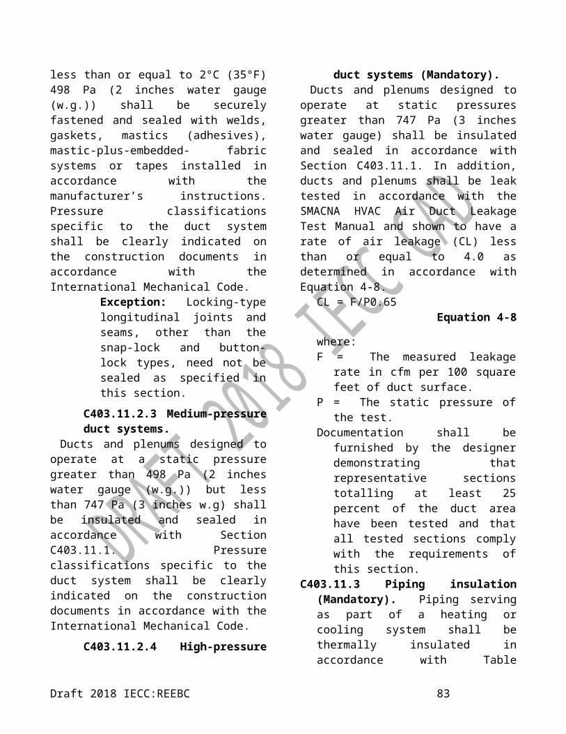
8. Lighting for theatrical purposes, including performance, stage, film production and video production.9. Lighting for photographic processes.10. Lighting integral to equipment or instrumentation and installed by the manufacturer.11. Task lighting for plant growth or maintenance.12. Advertising signage or directional signage.13. Lighting for food warming.14. Lighting equipment that is for sale.15. Lighting demonstration equipment in lighting education facilities.16. Lighting approved because of safety considerations.17. Lighting in retail display windows, provided that the display area is enclosed by ceiling-height partitions.18. Furniture-mounted supplemental task lighting that is controlled by automatic shutoff.19. Exit signs.
C405.3.2 Interior lighting power allowance. 2018 IECC shall apply.
C405.3.2.1 Building Area Method. 2018 IECC shall apply.C405.3.2.2 Space-by-Space Method. 2018 IECC shall apply.
C405.3.2.2.1 Additional interior lighting power. Where using the Space-by-Space Method, an increase in the interior lighting power allowance is permitted for specific lighting functions. Additional power shall be permitted only where the specified lighting is installed and automatically controlled separately from the general lighting, to be turned off during nonbusiness hours. This additional power shall be used only for the specified luminaires and shall not be used for any other
purpose. An increase in the interior lighting power allowance is permitted in the following cases:1. For lighting equipment to be installed in sales areas specifically to highlight merchandise, the additional lighting power shall be determined in accordance with Equation 4-10.Additional interior lighting power allowance = 1000 W + (Retail Area 1 × 4.8 W/m²) + (Retail Area 2 × 4.84 W/m²) + (Retail Area 3× 11 W/m²) + (Retail Area 4 × 20 W/m²)For IP units:Additional interior lighting power allowance = 1000 W + (Retail Area 1 × 0.45 W/ft²) + (Retail Area 2 × 0.45W/ft²) + (Retail Area 3 ×1.05 W/ft²) + (Retail Area 4 × 1.87 W/ft²)
Equation 4-10
where:Retail Area 1 = The floor area
for all products not listed in Retail Area 2, 3 or 4.
Retail Area 2 = The floor area used for the sale of vehicles, sporting goods and small electronics.
Retail Area 3 = The floor area used for the sale of furniture, clothing, cosmetics and artwork.
Retail Area 4 = The floor area used for the sale of jewelry,
Draft 2018 IECC:REEBC 85

crystal and china.
Exception: Other merchandise categories are permitted to be included in Retail Areas 2 through 4, provided that justification documenting the need for additional lighting power based on visual inspection, contrast, or other critical display is approved by the code official.
2. For spaces in which lighting is specified to be installed in addition to the general lighting for the purpose of decorative appearance or for highlighting art or exhibits, provided that the additional lighting power shall be not more than 9.7 W/m² (0.9 W/ft²) in lobbies and not more than 8.1 W/m² (0.75 W/ft²) in other spaces.
TABLE C405.4.2(1)INTERIOR LIGHTING POWER ALLOWANCES:
BUILDING AREA METHOD
BUILDING AREA TYPELPD
W/m² (W/ft²)Automotive facility 7.60 (0.71)Convention center 8.20 (0.76)Courthouse 9.70 (0.90)Dining: bar lounge/leisure 9.70 (0.90)Dining: cafeteria/fast food 8.50 (0.79)Dining: family 8.40 (0.78)Dormitorya, b 6.60 (0.61)Exercise center 7.00 (0.65)Fire stationa 5.70 (0.53)Gymnasium 7.30 (0.68)Health care clinic 8.80 (0.82)Hospitala 11.30 (1.05)Hotel/Motela, b 8.10 (0.75)Library 8.40 (0.78)Manufacturing facility 9.70 (0.90)Motion picture theater 8.90 (0.83)Multifamilyc 7.30 (0.68)Museum 11.40 (1.06)Office 8.50 (0.79)Parking garage 1.60 (0.15)Penitentiary 8.10 (0.75)Performing arts theater 12.70 (1.18)Police station 8.60 (0.80)Post office 7.20 (0.67)Religious building 10.10 (0.94)Retail 11.40 (1.06)School/university 8.70 (0.81)Sports arena 9.40 (0.87)Town hall 8.60 (0.80)Transportation 6.60 (0.61)Warehouse 5.20 (0.48)Workshop 9.70 (0.90)a. Where sleeping units are excluded from lighting power calculations by application of Section R405.1, neither the area of the sleeping units nor the wattage of lighting in the sleeping units is counted.b. Where dwelling units are excluded from lighting power calculations by application of Section R405.1, neither the area of the dwelling units nor the wattage of lighting in the dwelling units is counted.c. Dwelling units are excluded. Neither the area of the dwelling units nor the wattage of lighting in the dwelling units is counted.
Draft 2018 IECC:REEBC 86

TABLE C405.4.2(2)INTERIOR LIGHTING POWER ALLOWANCES:
SPACE-BY-SPACE METHOD
COMMON SPACE TYPESa LPDW/m² (W/ft²)
Atrium
Less than 12.2 m (40 feet) in height
0.10 per mtotal height
(0.03 per foot in total height)
Greater than 12.2 m (40 feet) in height
0.40 + 0.07 per m total height
(0.40 + 0.02 per foot in total height)
Audience seating areaIn an auditorium 6.8 (0.63)In a convention center 8.9 (0.82)In a gymnasium 7.1 (0.65)In a motion picture theater 12.3 (1.14)In a penitentiary 3.1 (0.28)In a performing arts theater 21.8 (2.03)In a religious building 16.5 (1.53)In a sports arena 4.7 (0.43)Otherwise 4.7 (0.43)
Banking activity area 9.26 (0.86)Breakroom (See Lounge/Breakroom)Classroom/lecture hall/training room
In a penitentiary 14.5 (1.34)Otherwise 10.3 (0.96)
Computer Room 14.3 (1.33)Conference/meeting/multipurpose room 10.3 (1.07)
Copy/print room 6 (0.56)Corridor
In a facility for the visually impaired (and not used primarily by the staff)b
9.9 (0.92)
In a hospital 9.9 (0.92)In a manufacturing facility 3.1 (0.29)Otherwise 7.1 (0.66)
Courtroom 18.51 (1.39)Dining area
In a penitentiary 10.3 (0.93)In a facility for the visually
impaired (and not used primarily by the staff)b
21.5 (0.63)
In bar/lounge or leisure dining 10 (2.00)
In cafeteria or fast food dining 6.8 (0.71)
In family dining 7.6 (0.96)Otherwise 6.8 (0.63)
Electrical/mechanical room 4.6 (0.43)Emergency vehicle garage 4.4 (0.41)
(continued)
TABLE C405.4.2(2)—continuedINTERIOR LIGHTING POWER ALLOWANCES:
SPACE-BY-SPACE METHOD
COMMON SPACE TYPESa LPDW/m² (W/ft²)
Food preparation area 11.40 (1.06)Guest room 8.30 (0.77)LaboratoryIn or as a classroom 12.90 (1.20)Otherwise 15.60 (1.45)Laundry/washing area 4.60 (0.43)Loading dock, interior 6.20 (0.58)Lobby
In a facility for the visually impaired (and not used primarily by the staff)b 21.80 (0.68)
For an elevator 7.30 (2.03)In a hotel 11.50 (1.06)In a motion picture theater 4.80 (0.45)In a performing arts theater 18.30 (1.70)Otherwise 10.80 (1.00)Locker room 5.20 (0.48)
Lounge/breakroomIn a healthcare facility 8.40 (0.78)Otherwise 6.70 (0.62)
OfficeEnclosed 10.00 (0.93)Open plan 10.00 (0.81)Parking area, interior 1.50 (0.14)Pharmacy area 14.40 (1.34)
RestroomIn a facility for the visually impaired
(and not used primarily by the staffb 10.30 (0.96)
Otherwise 9.10 (0.85)Sales area 13.10 (1.22)Seating area, general 15.30 (0.42)
Stairway (See space containing stairway)Stairwell 6.20 (0.58)Storage room 4.90 (0.46)Vehicular maintenance area 6.00 (0.56)Workshop 12.30 (1.14)
BUILDING TYPE SPECIFIC SPACE TYPESa W/m² (W/ft²)Automotive (See Vehicular Maintenance Area above)
Convention Center—exhibit space 9.50 (0.88)Dormitory—living quarters 5.80 (0.54)
Facility for the visually impairedb
In a chapel (and not used primarily by the staff) 11.40 (1.06)
Draft 2018 IECC:REEBC 87

In a recreation room (and not used primarily by the staff)
19.40 (1.80)
Fire Station—sleeping quarters 2.20 (0.20)Gymnasium/fitness center
In an exercise area 5.40 -0.5In a playing area 8.80 (0.82)
(continued)
TABLE C405.4.2(2)—continuedINTERIOR LIGHTING POWER ALLOWANCES:
SPACE-BY-SPACE METHODBUILDING TYPE SPECIFIC SPACE
TYPESaLPD
W/m² (W/ft²)Healthcare facility
In an exam/treatment room 18.1 (1.68)In an imaging room 11.4 (1.06)In a medical supply room 5.8 (0.54)In a nursery 10.8 (1.00)In a nurse’s station 8.7 (0.81)In an operating room 23.4 (2.17)In a patient room 6.7 (0.62)In a physical therapy room 9 (0.84)In a recovery room 11.1 (1.03)
LibraryIn a reading area 8.8 (0.82)In the stacks 12.9 (1.20)
Manufacturing facilityIn a detailed manufacturing area 10 (0.93)In an equipment room 7 (0.65)In an extra high bay area (greater
than 15.2 m [50 ft] floor-to-ceiling height)
11.3 (1.05)
In a high bay area (7.6 to 15.2 m [25-50 ft] floor-to-ceiling height) 8.1 (0.75)
In a low bay area (less than 7.6 m [25 ft] floor-to- ceiling height) 10.3 (0.96)
MuseumIn a general exhibition area 11.3 (1.05)In a restoration room 9.2 (0.85)
Performing arts theater—dressing room 3.9 (0.36)
Post Office—Sorting Area 7.3 (0.68)Religious buildings
In a fellowship hall 5.9 (0.55)In a worship/pulpit/choir area 16.5 (1.53)
Retail facilitiesIn a dressing/fitting room 5.4 (0.5)In a mall concourse 9.7 (0.9)
Sports arena—playing areaFor a Class I facility 26.6 (2.47)For a Class II facility 21.1 (1.96)For a Class III facility 18.3 (1.7)For a Class IV facility 12.2 (1.13)
(continued)
C405.4 Exterior lighting power requirements (Mandatory). 2018 IECC shall apply.
C405.4.1 Total connected exterior building exterior lighting power. 2018 IECC shall apply.
TABLE C405.4.2(2)—continuedINTERIOR LIGHTING POWER ALLOWANCES:
SPACE-BY-SPACE METHODBUILDING TYPE SPECIFIC
SPACE TYPESaLPD
W/m² (W/ft²)Transportation facility
In a baggage/carousel area 4.8 (0.45)In an airport concourse 3.3 (0.31)At a terminal ticket
counter 6.7 (0.62)
Warehouse—storage areaFor medium to bulky,
palletized items 3.8 (0.35)
For smaller, hand-carried items 7.4 (0.69)
a. In cases where both a common space type and a building area specific space type are listed, the building area specific space type shall applyb. A ‘Facility for the Visually Impaired’ is a facility that is licensed or will be licensed by local or state authorities for senior long-term care, adult daycare, senior support or people with special visual needs.
c. Where sleeping units are excluded from lighting power calculations by application of Section R405.1, neither the area of the sleeping units nor the wattage of lighting in the sleeping units is counted.
d. Where dwelling units are excluded from lighting power calculations by application of Section R405.1, neither the area of the dwelling units nor the wattage of lighting in the dwelling units is counted.
e. Class I facilities consist of professional facilities; and semiprofessional, collegiate, or club facilities with seating for 5,000 or more spectators.
f. Class II facilities consist of collegiate and semiprofessional facilities with seating for fewer than 5,000 spectators; club facilities with seating for between 2,000 and 5,000 spectators; and amateur league and high-school facilities with seating for more than 2,000 spectators.
g. Class III facilities consist of club, amateur league and high-school facilities with seating for 2,000 or fewer spectators.
h. Class IV facilities consist of elementary school and recreational facilities; and amateur league and high-school facilities without provision for spectators.
Draft 2018 IECC:REEBC 88

TABLE C405.5.2(1) EXTERIOR LIGHTING ZONES
2018 IECC shall apply.
C405.4.2 Exterior lighting power allowance. 2018 IECC shall apply.
C405.4.2.1 Additional exterior lighting power.
2018 IECC shall apply.
C405.4.3 Gas lighting (Mandatory). 2018 IECC shall apply.
C405.5 Dwelling electrical meter (Mandatory).
2018 IECC shall apply.
C405.6 Electrical transformers (Mandatory).
2018 IECC shall apply.TABLE C405.6
MINIMUM NOMINAL EFFICIENCY LEVELS FOR 10 CFR 431 LOW-VOLTAGE DRY-TYPE DISTRIBUTION
TRANSFORMERS
2018 IECC shall apply.
C405.7 Electrical motors (Mandatory).
2018 IECC shall apply.
C405.8 Vertical and horizontal transportation systems and equipment.
2018 IECC shall apply.C405.8.1 Elevator cabs. For the luminaires in each elevator cab, not including signals and displays, the sum of the lumens divided by the sum of the watts shall be not less than 35 lumens per watt. Ventilation fans in elevators that do not have their own air-conditioning system shall not consume more than 0.70 W·s/L (0.33 watts/cfm) at the maximum rated speed of the fan. Controls shall be provided that will de-energize
ventilation fans and lighting systems when the elevator is stopped, unoccupied and with its doors closed for over 15 minutes.C405.8.2 Escalators and moving walks. 2018 IECC shall apply.
C405.8.2.1 Regenerative drive. An escalator designed either for one-way down operation only or for reversible operation shall have a variable frequency regenerative drive that supplies electrical energy to the building electrical system when the escalator is loaded with passengers whose combined weight exceeds 340 kg (750 pounds).
C405.9 Voltage drop in feeders and branch circuits.
2018 IECC shall apply.C405.10 Sub-metering (Mandatory). In new buildings with tenants, metering shall be provided for the entire building and individually for each tenant occupying 93 m² (total enclosed and unenclosed) (1,000 ft²) or more. Tenants shall have access to data collected for their space. A tenant is defined as “one who rents or leases from a landlord.”
Draft 2018 IECC:REEBC 89

TABLE C405.5.2(2)INDIVIDUAL LIGHTING POWER ALLOWANCES FOR BUILDING EXTERIORS
LIGHTING ZONESZone 1 Zone 2 Zone 3 Zone 4
Base Site Allowance 350W 400W 500W 900W
Uncovered Parking AreasParking areas and
drives 0.32 W/m2 0.43 W/m2 0.65 W/m2 0.86 W/m2
Building Grounds Building Grounds
Walkways less than 10 feet wide
1.6 1.6 2.0 2.3W/linear
metreW/linear
metreW/linear
metreW/linear
metreWalkways 10 feet
wide or greater, plaza areas special feature
areas
1.1 W/m2 1.1 W/m2 1.2 W/m2 1.5 W/m2
Dining areas 7.00 W/m2 7.00 W/m2 8.07 W/m2 10.23 W/m2Stairways 6.46 W/m2 7.53 W/m2 7.53 W/m2 7.53 W/m2
Pedestrian tunnels 1.29 W/m2 1.29 W/m2 1.51 W/m2 2.26 W/m2Landscaping 0.32 W/m2 0.43 W/m2 0.43 W/m2 0.43 W/m2
Building Entrances and Exits
Main entries46 46 69 69
W/linear metre of door width
W/linear metre of door width
W/linear metre of door width
W/linear metre of door width
Entry canopies 0.22 W/m2 2.69 W/m2 4.31 W/m2 4.31 W/m2Loading docks 3.77 W/m2 3.77 W/m2 3.77 W/m2 3.77 W/m2
Sales CanopiesFree-standing and
attached 0.43 W/m2 0.43 W/m2 6.46 W/m2 7.53 W/m2
Outdoor SalesOpen areas (including
vehicle sales lots) 0.07 W/m2 0.07 W/m2 1.15 W/m2 0.16 W/m2
Street frontage for vehicle sales lots in addition to “open area” allowance
23 23 69
No allowance W/linear metre
W/linear metre
W/linear metre
For IP: 1m = 3.28 ft., 1 W/m2 = 10.76 watt per square foot, 1 W/lin m = 3.28 watt per linear foot, W =watts
Draft 2018 IECC:REEBC 90

TABLE C405.5.2(3)INDIVIDUAL LIGHTING POWER ALLOWANCES FOR BUILDING EXTERIORS
LIGHTING ZONES
Zone 1 Zone 2 Zone 3 Zone 4
Building facades No allowance 0.81 W/m2 of grossabove-grade wall area
1.22 W/m2 of grossabove-grade wall area
1.61 W/m2 of grossabove-grade wall area
Automated teller machines (ATM) and night depositories 135 W per location plus 45 W per additional ATM per location
Uncovered entrances and gatehouse inspection stations at
guarded facilities1.6 W/m2 of area
Uncovered loading areas for law enforcement, fire, ambulance and other emergency service vehicles
3.77 W/m2 of area
Drive-up windows/doors 200 W per drive-through
Parking near 24-hour retail entrances 400 W per main entry
For IP: 1m = 3.28 ft., 1 W/m2 = 10.76 watt per square foot, 1 W/lin m = 3.28 watt per linear foot, W =watts
TABLE C405.6MINIMUM NOMINAL EFFICIENCY LEVELS FOR 10 CFR 431 LOW-VOLTAGE DRY-TYPE DISTRIBUTION
TRANSFORMERSkVAa Efficiency (%)b kVAa Efficiency (%)b
15 97.70 15 97.8925 98.00 30 98.23
37.5 98.20 45 98.4050 98.30 75 98.6075 98.50 112.5 98.74
100 98.60 150 98.83167 98.70 225 98.94250 98.80 300 99.02333 98.90 500 99.14
750 99.231000 99.28
a. kiloVolt-Amp rating.b. Nominal efficiencies shall be established in accordance with the DOE 10 CFR 431 test procedure for low-voltage dry-type transformers.
Draft 2018 IECC:REEBC 91

TABLE C405.7(2)MINIMUM NOMINAL FULL-LOAD EFFICIENCY FOR NEMA DESIGN C AND IEC DESIGN H MOTORS AT 60
HZa, b
MOTOR HORSEPOWER (STANDARD KILOWATT EQUIVALENT)
NOMINAL FULL-LOAD EFFICIENCY (%) AS OF JUNE 1, 2016
4 Pole 6 Pole 8 Pole
Enclosed Open Enclosed Open Enclosed Open
0.75 (1) 85.5 85.5 82.5 82.5 75.5 75.51.1 (1.5) 86.5 86.5 87.5 86.5 78.5 77.01.5 (2) 86.5 86.5 88.5 87.5 84.0 86.52.2 (3) 89.5 89.5 89.5 88.5 85.5 87.53.7 (5) 89.5 89.5 89.5 89.5 86.5 88.55.5 (7.5) 91.7 91.0 91.0 90.2 86.5 89.57.5 (10) 91.7 91.7 91.0 91.7 89.5 90.211 (15) 92.4 93.0 91.7 91.7 89.5 90.215 (20) 93.0 93.0 91.7 92.4 90.2 91.018.5 (25) 93.6 93.6 93.0 93.0 90.2 91.022 (30) 93.6 94.1 93.0 93.6 91.7 91.730 (40) 94.1 94.1 94.1 94.1 91.7 91.737 (50) 94.5 94.5 94.1 94.1 92.4 92.445 (60) 95.0 95.0 94.5 94.5 92.4 93.055 (75) 95.4 95.0 94.5 94.5 93.6 94.175 (100) 95.4 95.4 95.0 95.0 93.6 94.190 (125) 95.4 95.4 95.0 95.0 94.1 94.1110 (150) 95.8 95.8 95.8 95.4 94.1 94.1150 (200) 96.2 95.8 95.8 95.4 94.5 94.1a. Nominal efficiencies shall be established in accordance with DOE 10 CFR 431.b. For purposes of determining the required minimum nominal full-load efficiency of an electric motor that has a horsepower or kilowatt rating between two horsepower or two kilowatt ratings listed in this table, each such motor shall be deemed to have a listed horsepower or kilowatt rating, determined as follows:
1. A kW at or above the midpoint between the two consecutive kW shall be rounded up to the higher of the two kW.
2. A kW below the midpoint between the two consecutive kW shall be rounded down to the lower of the two kW.
3. A horsepower rating shall be directly converted from horsepower to kilowatts using the formula: 1 horsepower = 1.341 kilowatt. The conversion should be calculated to three significant decimal places, and the resulting horsepower shall be rounded in accordance with No. 1 or No. 2 above, as applicable.
TABLE C405.7(3)MINIMUM AVERAGE FULL LOAD EFICIENCY POLYPHASE SMALL ELECTRIC MOTORSa
MOTOR HORSEPOWERkW (hp)
OPEN MOTORSNumber of Poles 2 4 6
Synchronous Speed (RPM) 3600 1800 12000.19 (0.25) 65.6 69.5 67.50.25 (0.33) 69.5 73.4 71.40.37 (0.50) 73.4 78.2 75.30.56 (0.75) 76.8 81.1 81.7
0.75 (1) 77.0 83.5 82.51.1 (1.5) 84.0 86.5 83.8
Draft 2018 IECC:REEBC 92

1.5 (2) 85.5 86.5 N/A2.2 (3) 85.5 86.9 N/A
a. Average full load efficiencies shall be established in accordance with 10 CFR 431.
TABLE C405.7(4)MINIMUM AVERAGE FULL LOAD EFFICIENCY FOR
CAPACITOR-START CAPACITOR-RUN AND CAPACITOR-START INDUCTION-RUN SMALL ELECTRIC MOTORSa
MOTOR HORSEPOWERkW (hp)
OPEN MOTORSNumber of Poles 2 4 6
Synchronous Speed (RPM) 3600 1800 12000.19 (0.25) 66.6 68.5 62.20.25 (0.33) 70.5 72.4 66.60.37 (0.50) 72.4 76.2 76.20.56 (0.75) 76.2 81.8 80.2
0.75 (1) 80.4 82.6 81.11.1 (1.5) 81.5 83.8 N/A1.5 (2) 82.9 84.5 N/A2.2 (3) 84.1 N/A N/A
a. Average full load efficiencies shall be established in accordance with 10 CFR 431.
SECTION C406ADDITIONAL EFFICIENCY PACKAGE OPTIONS
C406.1 Requirements. 2018 IECC shall apply.C406.1.1 Tenant spaces. 2018 IECC shall apply.C406.2 More efficient HVAC equipment performance. 2018 IECC shall apply.
C406.3 Reduced lighting power density. 2018 IECC shall apply.C406.4 Enhanced digital lighting controls. 2018 IECC shall apply.C406.5 On-site renewable energy. The total minimum ratings of on-site renewable energy systems shall be one of the following:
1. Not less than 5.4 W/ m2 (1.71 Btu/h per square foot or 0.50 watts per square foot) of conditioned floor area.2. Not less than 3 percent of the energy used within the building for building mechanical and service water heating equipment and lighting regulated in Chapter 4.
C406.6 Dedicated outdoor air system. 2018 IECC shall apply.
C406.7 Reduced energy use in service water heating. 2018 IECC shall apply.
C406.7.1 Load fraction. The building service water-heating system shall have one or more of the following that are sized to provide not less than 60 percent of the building's annual hot water requirements, or sized to provide 100 percent of the building's annual hot water requirements if the building shall otherwise comply with Section C403.9.5:
1. Waste heat recovery from service hot water, heat- recovery chillers, building equipment, or process equipment.
2. On site renewable energy water-heating systems.
3. Heat pump water heating systems.C406.8 Enhanced envelope performance. 2018 IECC shall apply.C406.9 Reduced air infiltration. Air infiltration shall be verified by whole-building pressurization testing conducted in accordance with ASTM E779 or ASTM E1827 by an independent third party. The measured air-leakage rate of the building
Draft 2018 IECC:REEBC 93

envelope shall not exceed 2.0 L/s × m2 (0.25 cfm/ft2) under a pressure differential of 75 Pa (0.3 inches water column), with the calculated surface area being the sum of the above- and below-grade building envelope. A report that includes the tested surface area, floor area, air by volume, stories above grade, and leakage rates shall be submitted to the code official and the building owner.
Exception: For buildings having over 25 000 m2 (250,000 square feet) of conditioned floor area, air leakage testing need not be conducted on the whole building where testing is conducted on representative above-grade sections of the building. Tested areas shall total not less than 25 percent of the conditioned floor area and shall be tested in accordance with this section.
SECTION C407TOTAL BUILDING PERFORMANCE
C407.1 Scope. 2018 IECC shall apply.C407.2 Mandatory requirements. 2018 IECC shall apply.C407.3 Performance-based compliance. 2018 IECC shall apply.C407.4 Documentation. 2018 IECC shall apply.
C407.4.1 Compliance report. 2018 IECC shall apply.C407.4.2 Additional documentation. 2018 IECC shall apply.
C407.5 Calculation procedure. 2018 IECC shall apply.
C407.5.1 Building specifications. 2018 IECC shall apply.C407.5.2 Thermal blocks. 2018 IECC shall apply.
C407.5.2.1 HVAC zones designed. 2018 IECC shall apply.
C407.5.2.2 HVAC zones not designed. Where HVAC zones have not yet been designed, thermal blocks shall be defined based on similar internal load densities, occupancy, lighting,
thermal and temperature schedules, and in combination with the following guidelines:
1. Separate thermal blocks shall be assumed for interior and perimeter spaces. Interior spaces shall be those located more than 4.6 m (15 feet) from an exterior wall. Perimeter spaces shall be those located closer than 4.6 m (15 feet) from an exterior wall.2. Separate thermal blocks shall be assumed for spaces adjacent to glazed exterior walls: a separate zone shall be provided for each orientation, except orientations that differ by not more than 45 degrees (0.79 rad) shall be permitted to be considered to be the same orientation. Each zone shall include floor area that is 4.6 m (15 feet) or less from a glazed perimeter wall, except that floor area within 4.6 m (15 feet) of glazed perimeter walls having more than one orientation shall be divided proportionately between zones.3. Separate thermal blocks shall be assumed for spaces having floors that are in contact with the ground or exposed to ambient conditions from zones that do not share these features.4. Separate thermal blocks shall be assumed for spaces having exterior ceiling or roof assemblies from zones that do not share these features.
C407.5.2.3 Group R-2 occupancy buildings.
2018 IECC shall apply.
C407.5.2.4 Enthalpy Recovery Ventilation systems (ERVs).
An annual energy cost reduction may be claimed in the whole building performance method calculations for Enthalpy Recovery
Draft 2018 IECC:REEBC 94

Ventilation systems used in the proposed building. This annual energy cost reduction is applicable for buildings in which every HVAC system has a design supply airflow of less than 2.36 m 3 /s (5,000 cfm ). The annual energy cost reduction shall also be applicable to buildings where one or more HVAC systems in the building have a design supply flow equal to 2.36 m 3 /s (5,000 cfm) or greater but shall have minimum outdoor air supply less than 70 percent of the design supply airflow for that HVAC system. The annual energy cost shall be reduced by 6 percent of total HVAC annual energy use for buildings located in Climate Zones 0 and 1 and 4 percent of total HVAC annual energy use for buildings located in Climate Zone 2.
C407.6 Calculation software tools.
2018 IECC shall apply.
C407.6.1 Specific approval. 2018 IECC shall apply.
C407.6.2 Input values. 2018 IECC shall apply.
Draft 2018 IECC:REEBC 95

TABLE C407.5.1(1)SPECIFICATIONS FOR THE STANDARD REFERENCE AND PROPOSED DESIGNS
BUILDING COMPONENT CHARACTERISTICS STANDARD REFERENCE DESIGN PROPOSED DESIGN
Space use classification Same as proposed
The space use classification shall be chosen in accordance with Table C405.5.2 for all areas of the building covered by this permit. Where the
space use classification for a building is not known, the building shall be categorized as an
office building.
Roofs
Type: Insulation entirely above deck As proposed
Gross area: same as proposed As proposed
U-factor: as specified in Table C402.1.3 As proposed
Solar absorptance: 0.75 As proposed
Emittance: 0.90 As proposed
Walls, above-grade
Type: Mass wall where proposed wall is mass; otherwise steel-framed wall
As proposed
Gross area: same as proposed As proposed
U-factor: as specified in Table C402.1.3 As proposed
Solar absorptance: 0.75 As proposed
Emittance: 0.90 As proposed
Walls, below-grade
Type: Mass wall As proposed
Gross area: same as proposed As proposed
U-Factor: as specified in Table C402.1.3 with insulation layer on interior side of walls
As proposed
Floors, above-grade
Type: joist/framed floor As proposed
Gross area: same as proposed As proposed
U-factor: as specified in Table C402.1.3 As proposed
Floors, slab-on-gradeType: Unheated As proposed
F-factor: as specified in Table C402.1.3 As proposed
Opaque doors
Type: Swinging As proposed
Area: Same as proposed As proposed
U-factor: as specified in Table C402.1.3 As proposed
Vertical fenestration other than opaque doors
Area1. The proposed glazing area; where the proposed glazing area is less
than 40 percent of above-grade wall area.2. 40 percent of above-grade wall area; where the proposed glazing
area is 40 percent or more of the above-grade wall area.
As proposed
U-factor: as specified in Table C402.1.3 As proposed
SHGC: as specified in Table C402.1.3 except that for climates with no requirement (NR) SHGC = 0.40 shall be used As proposed
External shading and PF: None As proposed
Skylights
Area1. The proposed skylight area; where the proposed skylight area is
less than that permitted by Section C402.1.2. The area permitted by Section C402.1; where the proposed skylight
area exceeds that permitted by Section C402.1
As proposed
U-factor: as specified in Table C402.4 As proposedSHGC: as specified in Table C402.4 except that for climates with no requirement (NR) SHGC = 0.40 shall be used. As proposed
Lighting, interior
The interior lighting power shall be determined in accordance with Section C405.3.2. Where the occupancy of the building is not known, the lighting power density shall be 10.7 W/m² (1.0 Watt per square foot) based on the categorization of buildings with unknown space classification as offices.
As proposed
Draft 2018 IECC:REEBC 96

Lighting, exteriorThe lighting power shall be determined in accordance with Table C405.5.2(2) and C405.4.2(3). Areas and dimensions of surfaces shall be the same as proposed.
As proposed
(continued)TABLE C407.5.1(1)—continued
SPECIFICATIONS FOR THE STANDARD REFERENCE AND PROPOSED DESIGNS
2018 IECC shall apply.
TABLE C407.5.1(2)HVAC SYSTEMS MAP
2018 IECC shall apply.
Draft 2018 IECC:REEBC 97

TABLE C407.5.1(3)SPECIFICATIONS FOR THE STANDARD REFERENCE DESIGN HVAC SYSTEM DESCRIPTIONS
SYSTEM NO. SYSTEM TYPE FAN CONTROL COOLING TYPE HEATING TYPE
1 Variable air volume with parallel fan-powered
boxesaVAVd Chilled watere Electric resistance
2 Variable air volume with reheatb VAVd Chilled watere Hot water fossil fuel boilerf
3Packaged variable air volume with parallel fan-
powered boxesa VAVd Direct expansionc Electric resistance
4 Packaged variable air volume with reheatb VAVd Direct expansionc Hot water fossil fuel boilerf
5 Two-pipe fan coil Constant volumei Chilled watere Electric resistance
6 Water-source heat pump Constant volumei Direct expansionc Electric heat pump and boilerg
7 Four-pipe fan coil Constant volumei Chilled watere Hot water fossil fuel boilerf
8 Packaged terminal heat pump Constant volumei Direct expansionc Electric heat pumph
9 Packaged rooftop heat pump Constant volumei Direct expansionc Electric heat pumph
10 Packaged terminal air conditioner Constant volumei Direct expansion Hot water fossil fuel boilerf
11 Packaged rooftop air conditioner Constant volumei Direct expansion Fossil fuel furnace
Draft 2018 IECC:REEBC 98

For IP: 1 m = 3.28 ft, 1 L/s = 2.13 cfm/ft², 1 W = 3,412 Btu/h, °C = [(°F) -32/1.8].a. VAV with parallel boxes: Fans in parallel VAV fan-powered boxes shall be sized for 50 percent of the peak design flow rate and shall be modeled with
0.35 W/cfm fan power. Minimum volume setpoints for fan-powered boxes shall be equal to the minimum rate for the space required for ventilation consistent with Section C403.4.5, Exception 4. Supply air temperature setpoint shall be constant at the design condition.
b. VAV with reheat: Minimum volume setpoints for VAV reheat boxes shall be 0.19 L/s (0.4 cfm/ft²) of floor area. Supply air temperature shall be reset based on zone demand from the design temperature difference to a -12°C (10°F) temperature difference under minimum load conditions. Design airflow rates shall be sized for the reset supply air temperature, i.e., a -12°C (10°F) temperature difference.
c. Direct expansion: The fuel type for the cooling system shall match that of the cooling system in the proposed design.d. VAV: Where the proposed design system has a supply, return or relief fan motor 18.6 kW (25 hp) or larger, the corresponding fan in the VAV system of
the standard reference design shall be modeled assuming a variable-speed drive. For smaller fans, a forward-curved centrifugal fan with inlet vanes shall be modeled. Where the proposed design’s system has a direct digital control system at the zone level, static pressure setpoint reset based on zone requirements in accordance with Section C403.8.5 shall be modeled.
e. Chilled water: For systems using purchased chilled water, the chillers are not explicitly modeled and chilled water costs shall be based as determined in Sections C407.3 and C407.5.2. Otherwise, the standard reference design’s chiller plant shall be modeled with chillers having the number as indicated in Table C407.5.1(4) as a function of standard reference building chiller plant load and type as indicated in Table C407.5.1(5) as a function of individual chiller load. Where chiller fuel source is mixed, the system in the standard reference design shall have chillers with the same fuel types and with capacities having the same proportional capacity as the proposed design’s chillers for each fuel type. Chilled water supply temperature shall be modeled at 7°C (44°F) design supply temperature and 13°C (56°F) return temperature. Piping losses shall not be modeled in either building model. Chilled water supply water temperature shall be reset in accordance with Section C403.9.3. Pump system power for each pumping system shall be the same as the proposed design; where the proposed design has no chilled water pumps, the standard reference design pump power shall be 1.4 W·s/L (22 W/gpm) (equal to a pump operating against a 22.9 m (75-foot) head, 65-percent combined impeller and motor efficiency). The chilled water system shall be modeled as primary-only variable flow with flow maintained at the design rate through each chiller using a bypass. Chilled water pumps shall be modeled as riding the pump curve or with variable-speed drives where required in Section C403.9.3. The heat rejection device shall be an axial fan cooling tower with two-speed fans where required in Section C403.9. Condenser water design supply temperature shall be 29°C (85°F) or -12°C (10°F) approach to design wet-bulb temperature, whichever is lower, with a design temperature rise of -12°C (10°F). The tower shall be controlled to maintain a 21°C (70°F) leaving water temperature where weather permits, floating up to leaving water temperature at design conditions. Pump system power for each pumping system shall be the same as the proposed design; where the proposed design has no condenser water pumps, the standard reference design pump power shall be 1.2·s/L (19 W/gpm) (equal to a pump operating against a 18.3 m (60-foot) head, 60-percent combined impeller and motor efficiency). Each chiller shall be modeled with separate condenser water and chilled water pumps interlocked to operate with the associated chiller.
f. Fossil fuel boiler: For systems using purchased hot water or steam, the boilers are not explicitly modeled and hot water or steam costs shall be based on actual utility rates. Otherwise, the boiler plant shall use the same fuel as the proposed design and shall be natural draft. The standard reference design boiler plant shall be modeled with a single boiler where the standard reference design plant load is 176 kW (600,000 Btu/h) and less and with two equally sized boilers for plant capacities exceeding 176 kW (600,000 Btu/h). Boilers shall be staged as required by the load. Hot water supply temperature shall be modeled at 82°C (180°F) design supply temperature and 54°C (130°F) return temperature. Piping losses shall not be modeled in either building model. Hot water supply water temperature shall be reset in accordance with Section C403.9.3. Pump system power for each pumping system shall be the same as the proposed design; where the proposed design has no hot water pumps, the standard reference design pump power shall be 1.2·s/L (19 W/gpm) (equal to a pump operating against a 18.3 m (60-foot) head, 60-percent combined impeller and motor efficiency). The hot water system shall be modeled as primary only with continuous variable flow. Hot water pumps shall be modeled as riding the pump curve or with variable speed drives where required by Section C403.9.3.
g. Electric heat pump and boiler: Water-source heat pumps shall be connected to a common heat pump water loop controlled to maintain temperatures between 16°C (60°F) and 32°C (90°F). Heat rejection from the loop shall be provided by an axial fan closed-circuit evaporative fluid cooler with two-speed fans where required in Section C403.8.5. Heat addition to the loop shall be provided by a boiler that uses the same fuel as the proposed design and shall be natural draft. Where no boilers exist in the proposed design, the standard reference building boilers shall be fossil fuel. The standard reference design boiler plant shall be modeled with a single boiler where the standard reference design plant load is 176 kW (600,000 Btu/h) or less and with two equally sized boilers for plant capacities exceeding 176 kW (600,000 Btu/h). Boilers shall be staged as required by the load. Piping losses shall not be modeled in either building model. Pump system power shall be the same as the proposed design; where the proposed design has no pumps, the standard reference design pump power shall be 1.4 W·s/L (22 W/gpm), which is equal to a pump operating against a 22.9 m (75-foot) head, with a 65-percent combined impeller and motor efficiency. Loop flow shall be variable with flow shutoff at each heat pump when its compressor cycles off as required by Section C403.9.3. Loop pumps shall be modeled as riding the pump curve or with variable speed drives where required by Section C403.9.3.
h. Electric heat pump: Electric air-source heat pumps shall be modeled with electric auxiliary heat. The system shall be controlled with a multistage space thermostat and an outdoor air thermostat wired to energize auxiliary heat only on the last thermostat stage and when outdoor air temperature is less than 4°C (40°F).
i. Constant volume: Fans shall be controlled in the same manner as in the proposed design; i.e., fan operation whenever the space is occupied or fan operation cycled on calls for heating and cooling. Where the fan is modeled as cycling and the fan energy is included in the energy efficiency rating of the equipment, fan energy shall not be modeled explicitly.
SECTION C408 SYSTEM COMMISSIONING
C408.1 General. 2018 IECC shall apply.
C408.1.1 Building operations and maintenance information.
2018 IECC shall apply.C408.2 Mechanical systems and service water-
heating systems commissioning and completion requirements. Prior to the final mechanical and plumbing inspections, the registered design professional or approved agency shall pro- vide evidence of mechanical systems commissioning and completion in accordance with the provisions of this section.
Draft 2018 IECC:REEBC 99

Construction document notes shall clearly indicate provisions for commissioning and completion requirements in accordance with this section and are permitted to refer to specifications for further requirements. Copies of all documentation shall be given to the owner or owner’s authorized agent and made available to the code official upon request in accordance with Sections C408.2.4 and C408.2.5.
Exceptions: The following systems are exempt:
1. Mechanical systems and service water heater systems in buildings where the total mechanical equipment capacity is less than 141 kW (480,000 Btu/h) cooling capacity and 176 kW (600,000 Btu/h) combined service water-heating and space-heating capacity.2. Systems included in Section C403.5 that serve individual dwelling units and sleeping units.
C408.2.1 Commissioning plan. 2018 IECC shall apply.C408.2.2 Air distribution system testing, adjusting and balancing. Construction documents shall require that a written balance report be provided to the owner or the designated representative of the building owner for HVAC systems serving zones with a total conditioned area exceeding 465 m² (5000 square feet ). Air distribution systems shall be tested, adjusted and balanced by a licensed engineer or an individual who holds a current certification from a recognized testing and balancing agency organization in accordance with generally accepted engineering standards.
Exceptions: 1. Buildings with cooling or heating
system capacities of 53 kW (15 tons) or less per system may be tested and balanced by a mechanical contractor licensed to design and install such system(s).
2. Buildings with cooling or heating system capacities of 19 kW (65,000 Btu/h) or less per system are exempt from the requirements of this section.
C408.2.2.1 Air systems balancing.Air system balancing shall be accomplished in a manner to first minimize throttling losses; then for fans with fan system power greater than 0.75 kW (1 hp), fan speeds shall be adjusted to meet design flow conditions. Balancing procedures shall be in accordance with the National Environmental Balancing Bureau (NEBB) Procedural Standards, the Associated Air Balance Council (AABC) National Standards, or equivalent procedures.
Exception: Damper throttling may be used for air system balancing with fan motors of 0.75 kW (1 hp) or less, or if throttling results in no greater than 0.25 kW (1/3 hp) fan horsepower draw above that required if the fan speed were adjusted. Notes:
1. Building envelope pressurization should be either neutral or positive to prevent infiltration of excess latent load.
2. Commercial kitchen hood exhaust L/s (cfm) shall be sized to prevent depressurization. Discharge dampers are prohibited on constant volume fans and variable volume fans with motors 7.5 kW (10 hp ) and larger.
C408.2.2.2 Hydronic systems balancing. Individual hydronic heating and cooling coils shall be equipped with means for balancing and measuring flow. Hydronic systems shall be proportionately balanced in a manner to first minimize throttling losses, then the pump impeller shall be trimmed or pump speed shall be adjusted to meet design
Draft 2018 IECC:REEBC 100

flow conditions. Each hydronic system shall have either the capability to measure pressure across the pump, or test ports at each side of each pump.
Exceptions: The following equipment is not required to be equipped with a means for balancing or measuring flow:
1. Pumps with pump motors of 3.7 kW (5 hp) or less.2. Where throttling results in no greater than 5 percent of the nameplate horsepower draw above that required if the impeller were trimmed.
C408.2.3 Functional performance testing. 2018 IECC shall apply.
C408.2.3.1 Equipment. 2018 IECC shall apply.C408.2.3.2 Controls. 2018 IECC shall apply.
C408.2.3.3 Economizers. 2018 IECC shall apply.
C408.2.4 Preliminary commissioning report. 2018 IECC shall apply.
C408.2.4.1 Acceptance of report. 2018 IECC shall apply.C408.2.4.2 Copy of report. 2018 IECC shall apply.
C408.2.5 Documentation requirements. 2018 IECC shall apply.
C408.2.5.1 System balancing report. 2018 IECC shall apply.
C408.2.5.2 Final commissioning report. 2018 IECC shall apply.
C408.3 Functional testing of lighting controls.2018 IECC shall apply.
C408.3.1 Functional testing. 2018 IECC shall apply.
C408.3.1.1 Occupant sensor controls. 2018 IECC shall apply. C408.3.1.2 Time-switch controls. 2018 IECC shall apply.C408.3.1.3 Daylight responsive controls. 2018 IECC shall apply.
C408.3.2 Documentation requirements.
2018 IECC shall apply.
C408.3.2.1 Drawings. 2018 IECC shall apply.
C408.3.2.2 Manuals. 2018 IECC shall apply.
C408.3.2.3 Report. 2018 IECC shall apply.
Draft 2018 IECC:REEBC 101

CHAPTER 5 [CE]EXISTING BUILDINGS
SECTION C501GENERAL
C501.1 Scope. 2018 IECC shall apply.C501.2 Existing buildings. 2018 IECC shall apply.C501.3 Maintenance. 2018 IECC shall apply.
C501.4 Compliance.
Alterations, repairs, additions and changes of occupancy to, or relocation of, existing buildings and structures shall comply with the provisions for alterations, repairs, additions and changes of occupancy or relocation, respectively, in this code and in the International Building Code, International Existing Building Code, Inter- national Fire Code, International Fuel Gas Code, International Mechanical Code, International Plumbing Code, International Property Maintenance Code, International Private Sewage Disposal Code, NFPA 70 and standards approved by the Authority having Jurisdiction.C501.5 New and replacement materials. 2018 IECC shall apply.C501.6 Historic buildings. 2018 IECC shall apply.
SECTION C502ADDITIONS
C502.1 General. 2018 IECC shall apply.C502.2 Prescriptive compliance. 2018 IECC shall apply.
C502.2.1 Vertical fenestration. 2018 IECC shall apply.C502.2.2 Skylight area. 2018 IECC shall apply.C502.2.3 Building mechanical systems. 2018 IECC shall apply.C502.2.4 Service water-heating systems.
2018 IECC shall apply.C502.2.5 Pools and inground permanently installed spas. 2018 IECC shall apply.C502.2.6 Lighting power and systems. 2018 IECC shall apply.
C502.2.6.1 Interior lighting power. 2018 IECC shall apply.C502.2.6.2 Exterior lighting power. 2018 IECC shall apply.
SECTION C503ALTERATIONS
C503.1 General. 2018 IECC shall apply. C503.2 Change in space conditioning. Any nonconditioned or low energy intensity space that is altered to become conditioned space shall be required to be brought into full compliance with this code.C503.3 Building envelope. 2018 IECC shall apply.
C503.3.1 Roof replacement. Roof replacements shall comply with Section C402.1.3, C402.1.4, C402.1.5 or C407 where the existing roof assembly is part of the building thermal envelope.C503.3.2 Vertical fenestration 2018 IECC shall apply.C503.3.3 Skylight area. 2018 IECC shall apply.
C503.4 Heating and cooling systems.
2018 IECC shall apply.C503.4.1 Economizers. 2018 IECC shall apply.
C503.5 Service hot water systems.
2018 IECC shall apply.
C503.6 Lighting systems.
2018 IECC shall apply.
Draft 2018 IECC:REEBC 102

SECTION C504REPAIRS
C504.1 General. 2018 IECC shall apply. C504.2 Application. 2018 IECC shall apply.
SECTION C505CHANGE OF OCCUPANCY OR USE
C505.1 General. 2018 IECC shall apply.
Draft 2018 IECC:REEBC 103
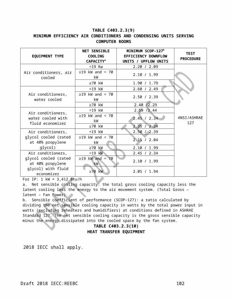
CHAPTER 6REFERENCED STANDARDS
2018 IECC shall apply.
Draft 2018 IECC:REEBC 104

RESIDENTIAL PROVISIONS
CHAPTER 1[RE]SCOPE AND ADMINISTRATION
PART 1 - SCOPE AND APPLICATION
SECTION R101SCOPE AND GENERAL REQUIREMENTS
R101.1 Title. This code shall be known as the 20XX Regional Energy Efficiency Building Code,
and shall be cited as such. It is referred to herein as “this code.”R101.2 Scope. 2018 IECC shall apply.R101.3 Intent. 2018 IECC shall apply.R101.4 Applicability. 2018 IECC shall apply.
Draft 2018 IECC:REEBC 105

R101.4.1 Mixed occupancy.
2018 IECC shall apply.R101.5 Compliance. 2018 IECC shall apply.
R101.5.1 Compliance materials.
2018 IECC shall apply.
SECTION R102ALTERNATIVE MATERIALS, DESIGN AND
METHODS OF CONSTRUCTION AND EQUIPMENT
R102.1 General. 2018 IECC shall apply.
R102.1.1 Above code programs.
2018 IECC shall apply.PART 2 - ADMINISTRATION AND ENFORCEMENT
SECTION R103CONSTRUCTION DOCUMENTS
R103.1 General. Construction documents, technical reports and other supporting data shall be submitted in one or more sets with each application for a permit. The construction documents and technical reports shall be prepared by a registered design professional as prescribed by the local jurisdiction or national regulatory authority.
Exception: The code official is authorized to waive the requirements for construction documents or other supporting data if the code official determines they are not necessary to confirm compliance with this code.
R103.2 Information on construction documents. 2018 IECC shall apply.
R103.2.1 Building thermal envelope depiction.
2018 IECC shall apply.R103.3 Examination of documents. 2018 IECC shall apply.
R103.3.1 Approval of construction documents.
2018 IECC shall apply.
R103.3.2 Previous approvals. 2018 IECC shall apply.
R103.3.3 Phased approval. 2018 IECC shall apply.R103.4 Amended construction documents.2018 IECC shall apply.R103.5 Retention of construction documents.2018 IECC shall apply.
SECTION R104INSPECTIONS
R104.1 General. 2018 IECC shall apply.R104.2 Required inspections. 2018 IECC shall apply.
R104.2.1 Footing and foundation inspection.
2018 IECC shall apply.
R104.2.2 Framing and rough-in inspection. 2018 IECC shall apply.
R104.2.3 Plumbing rough-in inspection. 2018 IECC shall apply.
R104.2.4 Mechanical rough-in inspection. 2018 IECC shall apply.
Exception: Systems serving multiple dwelling units shall be inspected in accordance with Section C104.2.4.
R104.2.5 Final inspection. 2018 IECC shall apply.R104.3 Reinspection. 2018 IECC shall apply.R104.4 Approved inspection agencies. 2018 IECC shall apply.R104.5 Inspection requests. 2018 IECC shall apply.R104.6 Reinspection and testing. 2018 IECC shall apply.R104.7 Approval. 2018 IECC shall apply.
R104.7.1 Revocation. 2018 IECC shall apply.
Draft 2018 IECC:REEBC 106

SECTION R105VALIDITY
R105.1 General. 2018 IECC shall apply.
SECTION R106 REFERENCED STANDARDS
R106.1 Referenced codes and standards. 2018 IECC shall apply.
R106.1.1 Conflicts. 2018 IECC shall apply.
R106.1.2 Provisions in referenced codes and standards.
2018 IECC shall apply.R106.2 Application of references. 2018 IECC shall apply.
R106.3 Other laws.
The provisions of this code shall not be deemed to nullify any provisions of local, state or national law. If local codes or requirements exceed the requirements set forth in this code, the most current provisions shall apply.
SECTION R107 FEES
R107.1 Fees. 2018 IECC shall apply.R107.2 Schedule of permit fees. 2018 IECC shall apply.R107.3 Work commencing before permit issuance. 2018 IECC shall apply.R107.4 Related fees. 2018 IECC shall apply.R107.5 Refunds. 2018 IECC shall apply.
SECTION R108 STOP WORK ORDER
R108.1 Authority. 2018 IECC shall apply.R108.2 Issuance. 2018 IECC shall apply.R108.3 Emergencies. 2018 IECC shall apply.R108.4 Failure to comply. 2018 IECC shall apply.
SECTION R109 BOARD OF APPEALS
R109.1 General. 2018 IECC shall apply.
R109.2 Limitations on authority. 2018 IECC shall apply.R109.3 Qualifications. 2018 IECC shall apply.
Draft 2018 IECC:REEBC 107

CHAPTER 2[RE]DEFINITIONS
SECTION R201 GENERALR201.1 Scope. 2018 IECC shall apply.R201.2 Interchangeability. 2018 IECC shall apply.R201.3 Terms defined in other codes. 2018 IECC shall apply.R201.4 Terms not defined. 2018 IECC shall apply.
SECTION R202GENERAL DEFINITIONS
ENERGY USE INTENSITY. Energy-use intensity (EUI): an expression of building energyuse per year in terms of net energy divided by gross floor
Draft 2018 IECC:REEBC 108

CHAPTER 3[RE]GENERAL REQUIREMENTS
SECTION R301CLIMATE ZONES
R301.1 General. Climate zones from Table R301.1 shall be used in determining the applicable requirements from Chapter 4 [RE]. Locations not in Table R301.1 shall be assigned a climate zone based on Section R301.3.R301.2 Warm humid locations. Warm humid locations are identified in Table R301.1 by an asterisk.R301.3 Unstated climate zones. The climate zone for any location not listed in Table R301.1 shall be determined by applying Table R301.3(1) and then Table R301.3(2).R301.4 Tropical climate zone. The tropical climate zone shall be defined as:1. Anguilla, Antigua and Barbuda, Bahamas,
Barbados, Belize, Bermuda, British Virgin Islands, Cayman Islands, Dominica, Grenada, Guyana, Haiti, Jamaica, Montserrat, Saint Lucia, St. Kitts and Nevis, St. Vincent and the Grenadines, Suriname, Trinidad and Tobago, Turks and Caicos Islands;
2. Islands in the area between the Tropic of Cancer and the Tropic of Capricorn.
SECTION R303 MATERIALS, SYSTEMS AND EQUIPMENT
R303.1 Identification. 2018 IECC shall apply.R303.1.1 Building thermal envelope insulation. An R- value identification mark shall be applied by the manufacturer to each piece of building thermal envelope insulation 305 mm (12 inches) or greater in width. Alternately, the insulation installers shall provide a certification listing the type, manufacturer and R-value of insulation installed in each element of the building thermal envelope. For blown or sprayed insulation (fiberglass and cellulose), the initial
installed thickness, settled thickness, settled R-value, installed density, coverage area and number of bags installed shall be listed on the certification. For sprayed polyurethane foam (SPF) insulation, the installed thick- ness of the areas covered and R-value of installed thick- ness shall be listed on the certification. For insulated siding, the R-value shall be labelled on the product’s pack- age and shall be listed on the certification. The insulation installer shall sign, date and post the certification in a conspicuous location on the job site.
R303.1.1.1 Blown or sprayed roof/ceiling insulation. The thickness of blown-in or sprayed roof/ceiling insulation (fiberglass or cellulose) shall be written in mm (inches) on markers that are installed at least one for every 28 m² (300 square feet) throughout the attic space. The markers shall be affixed to the trusses or joists and marked with the minimum initial installed thickness with numbers not less than 25 mm (1 inch) in height. Each marker shall face the attic access opening. Spray polyurethane foam thickness and installed R-value shall be listed on certification provided by the insulation installer.
R303.1.2 Insulation mark installation. 2018 IECC shall apply.
R303.1.3 Fenestration product rating. 2018 IECC shall apply.
R303.1.4 Insulation product rating. The thermal resistance (R-value) of insulation shall be determined in accordance with the U.S. Federal Trade Commission R-value rule (CFR Title 16, Part 460) in units of m²·K/W (h·ft²·°F/Btu) at a mean temperature of 24°C (75°F).
Draft 2018 IECC:REEBC 109

TABLE R303.1.3(1)DEFAULT GLAZED FENESTRATION U-FACTORS
FRAME TYPE
SINGLE PANE
DOUBLE PANE
SKYLIGHT
Single Double
Metal
6.81 W/m²·K
4.54 W/m²·K
11.36 W/m²·K
7.38 W/m²·K
(1.20Btu/h·ft²·°
F)
(0.80Btu/h·ft²·°
F)
(2.00Btu/h·ft²·°
F)
(1.30Btu/h·ft²·°
F)
Metal with
Thermal Break
6.25 W/m²·K
3.69 W/m²·K
10.79 W/m²·K
6.25 W/m²·K
(1.10Btu/h·ft²·°
F)
(0.65Btu/h·ft²·°
F)
(1.90Btu/h·ft²·°
F)
(1.10Btu/h·ft²·°
F)
Nonmetal or
Metal Clad
5.39 W/m²·K
3.12 W/m²·K
9.94 W/m²·K
5.96 W/m²·K
(0.95Btu/h·ft²·°
F)
(0.55Btu/h·ft²·°
F)
(1.75Btu/h·ft²·°
F)
(1.05Btu/h·ft²·°
F)
Glazed Block
3.41 W/m²·K
(0.60 Btu/h·ft²·°F)
TABLE R303.1.3(2) DEFAULT DOOR U-FACTORS
DOOR TYPE U-FACTOR
Uninsulated Metal6.81 W/m²·K
(1.20 Btu/h·ft²·°F)
Insulated Metal3.41 W/m²·K
(0.60 Btu/h·ft²·°F)
Wood2.84 W/m²·K
(0.50 Btu/h·ft²·°F)
Insulated, nonmetal edge, max 45% glazing, any glazing double
pane
1.99 W/m²·K
(0.35 Btu/h·ft²·°F)
TABLE R303.1.3(3)DEFAULT GLAZED FENESTRATION SHGC AND VT
2018 IECC shall apply.
R303.1.4 Insulation product rating. The thermal resistance (R-value) of insulation shall be determined in accordance with the
U.S. Federal Trade Commission R-value rule (CFR Title 16, Part 460) in units of m²·K/W (h·ft²·°F/Btu) at a mean temperature of 24°C (75°F).
R303.1.4.1 Insulated siding. 2018 IECC shall apply.
R303.2 Installation. 2018 IECC shall apply.R303.2.1 Protection of exposed foundation insulation. Insulation applied to the exterior of basement walls, crawl- space walls and the perimeter of slab-on-grade floors shall have a rigid, opaque and weather-resistant protective covering to prevent the degradation of the insulation’s thermal performance. The protective covering shall cover the exposed exterior insulation and extend not less than 153 mm (6 inches) below grade.
R303.3 Maintenance information. 2018 IECC shall apply.
Draft 2018 IECC:REEBC 110

TABLE R301.1 CLIMATE ZONES, MOISTURE REGIMES, AND WARM-HUMID DESIGNATIONS BY COUNTRY AND TERRITORY
Key: A – Moist, B – Dry, C – Marine. Absence of moisture designation indicates moisture regime is irrelevant.
CZSI I-P
COUNTRY LOCATION WMO# Elev (m) CDD10 HDD18 Precip (mm) Elev (ft) CDD50 HDD65 Precip (in)Anguilla (AIA)a WALLBLAKE 0A 6691 Antigua and Barbuda (ATG)b VC BIRD INTL AIRPORT 788620 0A 10 6249 0 883 33 11248 0 35Bahamas (BHS)b LYNDEN PINDLING INTL
AIRPORT 780730 1A 7 5643 9 1334 23 10157 16 53 SETTLEMENT POINT 994390 1A 3 5322 19 1281 10 9580 34 50Barbados (BRB)b GRANTLEY ADAMS 789540 0A 56 6308 0 1155 184 11354 0 45Belize (BLZ)b BELIZE/PHILLIP GOLD 785830 0A 5 6145 0 1944 16 11061 0 77Bermuda (BMU)b BERMUDA INTL 780160 2A 6 4596 88 1456 20 8273 158 57British Virgin Islands (VGB)a TERRANCE B. LETTSOME INTL AIRPORT 0A 6453 Cayman Islands (CYM)a OWEN ROBERTS AIRPORT 0A 6620 Dominica (DMA)a MELVILLE HALL AIRPORT 0A 6288 Grenada (GRD)b MAURICE BISHOP INTL
AIRPORT 789580 0A 7 6378 0 1197 23 11480 0 47Guyana (GUY)b
TIMEHRI\CHEDDI JAG 810020 0A 29 6136 0 2234 95 11045 0 88Haiti (HTI)a
Port-Au-Prince Aeroport Intl 0A 6848 Jamaica (JAM)b KINGSTON/NORMAN MAN 783970 0A 14 6608 0 730 46 11894 0 29 MONTEGO BAY/SANGSTE 783880 0A 8 6336 0 1184 26 11405 0 47Montserrat (MSR)a JOHN OSBORNE AIRPORT 1A 5946 Saint Lucia (LCA)b HEWANORRA INTL AIRP 789480 0A 10 6429 0 1128 33 11572 0 44St. Kitts and Nevis (KNA)a 0A 6388 St. Vincent and the Grenadines (VCT)a ARNOS VALE AIRPORT 0A 6647 Suriname (SUR)b ZANDERIJ 812250 0A 9 6264 0 2249 30 11275 0 89Trinidad and Tobago (TTO)b ARTHUR NAPOLEON
RAYMOND ROBINSON INTL AIRPORT 789620 0A 6 6307 0 1452 20 11353 0 57
PIARCO INT. AIRPORT 789700 0A 15 6274 0 1781 49 11293 0 70Turks and Caicos Islands (TCA)a 0A 6439 a. Calculated CARICOM Member State or Associateb. CARICOM Member State or Associate
(continued)
Draft 2018 IECC:REEBC 111
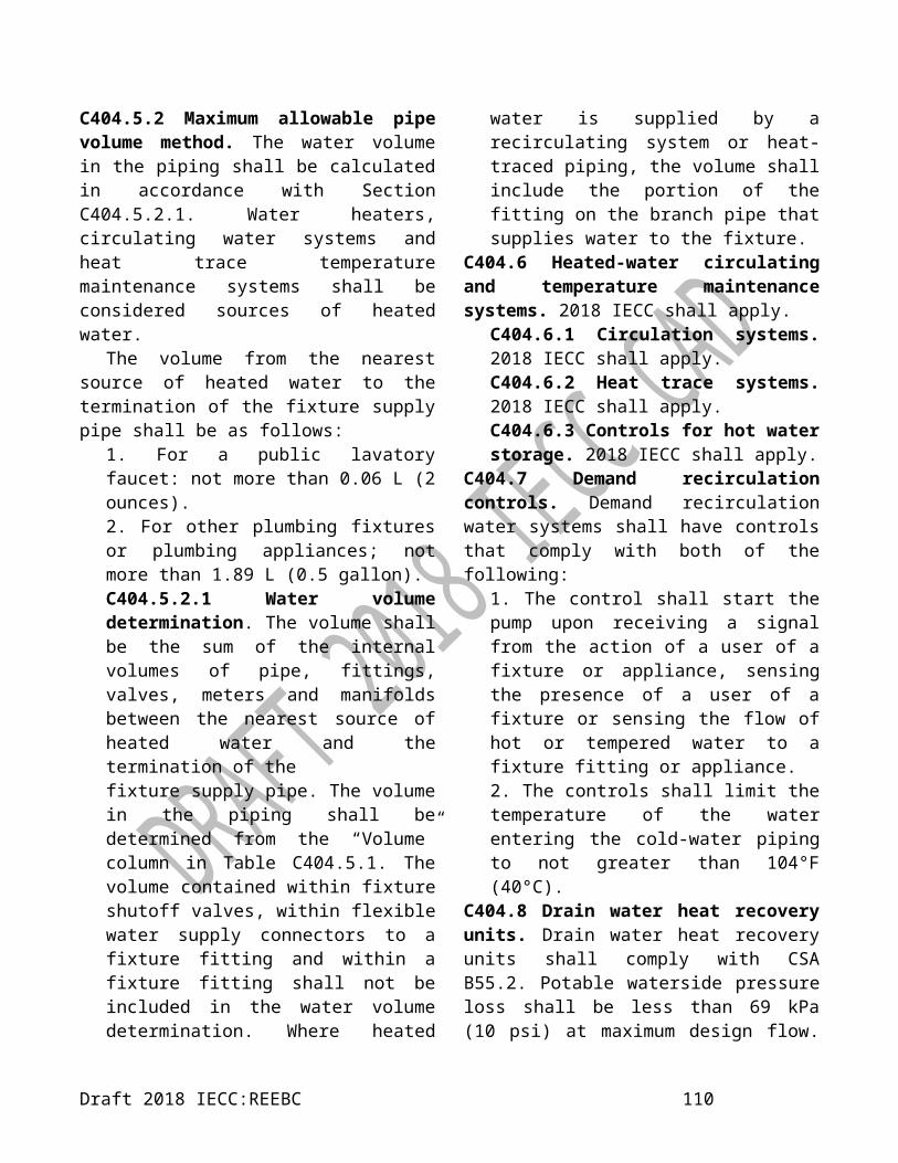
TABLE R301.1 continuedCLIMATE ZONES, MOISTURE REGIMES, AND WARM-HUMID DESIGNATIONS BY COUNTRY AND
TERRITORY
Degree-day: the difference in temperature between the out- door mean temperature over a 24-hour period and a given base temperature. For the purposes of determining building envelope requirements, the classifications are defined as follows:Cooling degree-day base 10°C, CDD10 (50°F, CDD50): for any one day, when the mean temperature is more than10°C (50°F), there are as many degree-days as degrees Fahrenheit or Celsius temperature difference between the mean temperature for the day and 10°C (50°F) (mean temperature 10°C (50°F)). Annual cooling degree- days (CDDs) are the sum of the degree-days over a calendar year.Heating degree-day base 18°C, HDD18 (65°F, HDD65): for any one day, when the mean temperature is less than 18°C (65°F), there are as many degree-days as degrees Fahrenheit or Celsius temperature difference between and 18°C (65°F) and the mean temperature for the day (18°C (65°F) minus the mean temperature). Annual heating degree-days (HDDs) are the sum of the degree-days over a calendar year.
Draft 2018 IECC:REEBC 112

TABLE R 301.3(1)UNSTATED CLIMATE ZONE DEFINITIONS
MAJOR CLIMATE TYPE DEFINITIONSMarine (C) Definition—Locations meeting all four criteria:5. Mean temperature of coldest month between 27°F (–3°C) and 65°F (18°C)6. Warmest month mean < 72°F (22°C)7. At least four months with mean temperatures over 50°F (10°C)8. Dry season in summer. The month with the heaviest precipitation in the cold season has at least
three times as much precipitation as the month with the least precipitation in the rest of the year. The cold season is October through March in the Northern Hemisphere and April through September in the Southern Hemisphere.
Dry (B) Definition—Locations meeting the following criteria:5. Not Marine (C)6. If 70% or more of the precipitation, P, occurs during the high sun period, then the dry/humid
threshold is Pin < 0.44 × (T – 7) (I-P) [Pmm < 20.0 × (T + 14) (SI)]7. If between 30% and 70% of the precipitation, P, occurs during the high sun period, then the
dry/humid threshold is Pin < 0.44 × (T – 19.5) (I-P) [Pmm < 20.0 × (T + 7) (SI)]8. If 30% or less of the precipitation, P, occurs during the high sun period, then the dry/humid
threshold is Pin < 0.44 × (T – 32) (I-P) [Pmm < 20 × T (SI)] where:P = annual precipitation, in. (mm)T = annual mean temperature, °F (°C)
Summer or high sun = April through September in the Northern Hemisphere and October through March period in the Southern Hemisphere
Winter or cold season = October through March in the Northern Hemisphere and April through September in the Southern Hemisphere
Humid (A) Definition—Locations that are not marine and not dry.Warm-humid Definition—Humid (A) locations where either of the following wet-bulb temperature conditions shall occur during the warmestsix consecutive months of the year:1. 67°F (19.4°C) or higher for 3,000 or more hours; or2. 73°F (22.8°C) or higher for 1,500 or more hours.For SI: °C = [(°F)-32]/1.8, 1 inch = 2.54 cm.
TABLE R301.3(2) UNSTATED CLIMATE ZONE DEFINITIONS [Source: ASHRAE STANDARD 169-2013]
Thermal Zone
Name I-P Units SI Units
0 Extremely hot 10,800 < CDD50°F 6000 < CDD10°C1 Very hot 9000 < CDD50°F ≤ 10,800 5000 < CDD10°C ≤ 60002 Hot 6300 < CDD50°F ≤ 9000 3500 < CDD10°C ≤ 50003 Warm CDD50°F ≤ 6300 CDD10°C ≤3500
Draft 2018 IECC:REEBC 113

and HDD65°F ≤ 3600 and HDD18°C ≤ 2000CHAPTER 4 [RE]
RESIDENTIAL ENERGY EFFICIENCY
SECTION R401 GENERAL
R401.1 Scope. 2018 IECC shall apply.R401.2 Compliance. Projects shall comply with one of the following:
1. Sections R401 through R404.2. Section R405 and the provisions of Sections R401 through R404 labelled “Mandatory.”3. An energy rating index (ERI) approach in Section R406.4. The Tropical zone requirements in Section R401.2.1.R401.2.1 Tropical zone. Residential buildings in the tropical zone at elevations below 2,400 feet (731.5 m) above sea level shall be deemed to comply with this chapter where the following conditions are met:
1. Not more than one-half of the occupied space is air conditioned.
2. The dwelling unit is not heated.3. Solar, wind or other renewable energy
source supplies not less than 90 percent of the energy for service water heating.
4. Glazing in dwelling units shall have a maximum solar heat gain coefficient as specified in Table R401.2.1.
5. Skylights in dwelling units shall have a maximum U-factor as specified in Table R401.2.1.
6. Permanently installed lighting is in accordance with Section R404.
7. The roof/ceiling complies with one of the following options: 1. Comply with one of the roof surface options in Table C402.3 and install R-2.3 (m²·K)/W (R-13 h·ft²·°F/Btu) insulation or greater.2. Install R-3.3 (m²·K)/W (R-19
h·ft²·°F/Btu) insulation or greater.If present, attics above the insulation are vented and attics below the insulation are unvented.
Exception: The roof/ceiling assembly is permitted to comply with Section R407.
TABLE R401.2.1BUILDING ENVELOPE FENESTRATION MAXIMUM U-
FACTOR AND SHGC REQUIREMENTS
CLIMATE ZONES 0 AND 1Vertical fenestration
U-factorFixed fenestration 2.84 W/m²·K (0.50
Btu/h·ft²·°F)Operable fenestration 3.69 W/m²·K (0.65
Btu/h·ft²·°F)Entrance doors 6.25 W/m²·K (1.10
Btu/h·ft²·°F)SHGC
Orientationa SEW NPF < 0.2 0.25 0.33
0.2 ≤ PF ≤ 0.5 0.30 0.370.5 ≤ PF 0.40 0.40
SkylightsU-factor 4.26 W/m²·K (0.75
Btu/h·ft²·°F)SHGC 0.35
NR = No requirement, PF = Projection factor.a. “N” indicates vertical fenestration oriented within 45 degrees of true north. “SEW” indicates orientations other than “N.” For buildings in the southern hemisphere, reverse south and north. Buildings located at less than 23.5 degrees latitude shall use SEW for all orientations.
8. Roof surfaces have a minimum slope of 21 millimetre per meter (¼ inch per foot) of run. The finished roof does not have water accumulation areas.
9. Operable fenestration provides ventilation area equal to not less than 14 percent of the floor area in each room.
Alternatively, equivalent ventilation is provided by a ventilation fan.
10. Bedrooms with exterior walls facing two different directions have operable
Draft 2018 IECC:REEBC 114

fenestration on exterior walls facing different directions.
11. Interior doors to bedrooms are capable of being secured in the open position.
12. A ceiling fan or ceiling fan rough-in is provided for bedrooms and the largest space that is not used as bedroom.
13. Jalousie windows shall have an air infiltration rate of no more than 6.1 L/s· m² (1.2 cfm per square foot ).
14. Walls, floors and ceilings separating air conditioned spaces from non-air conditioned spaces shall be constructed to limit air leakage in accordance with the requirements in Table R402.4.1.1.
SECTION R402 BUILDING THERMAL ENVELOPE
R402.1 General (Prescriptive). The building thermal envelope shall meet the requirements of Sections R402.1.1 through R402.1.5.
Exception: The following low energy use intensity buildings, or portions thereof, separated from the remainder of the building by building thermal envelope assemblies complying with this section shall be exempt from the building thermal envelope provisions of Section R402.
1. Those with a peak design rate of energy usage less than 3.4 Btu/h-ft² (10.7 W/m²) or 1.0 watt per square foot (10.7 W/m²) of floor area for space conditioning purposes.
2. Unconditioned space that does not contain habitable space.
R402.1.1 Vapor retarder. 2018 IECC shall apply.R402.1.2 Insulation and fenestration criteria. 2018 IECC shall apply.R402.1.3 R-value computation. 2018 IECC shall apply.
R402.1.4 U-factor alternative. An assembly with a U-factor equal to or less than that specified in Table R402.1.2 shall be permitted as an alternative to the R-value in Table R402.1.2.R402.1.5 Total UA alternative. If the total building thermal envelope UA (sum of U-factor times assembly area) is less than or equal to the total UA resulting from using the U-factors in Table R402.1.2 (multiplied by the same assembly area as in the proposed building), the building shall be considered in compliance with Table R402.1.2. The UA calculation shall be done using a method consistent with the ASHRAE Handbook of Fundamentals and shall include the thermal bridging effects of framing materials. The SHGC requirements shall be met in addition to UA compliance.
R402.2 Specific insulation requirements (Prescriptive). In addition to the requirements of Section R402.1, insulation shall meet the specific requirements of Sections R402.2.1 through R402.2.13.
Exception:Above-grade walls and ceilings shall be permitted to comply with Section R407.R402.2.1 Ceilings with attic spaces. Where Section R402.1.2 would require R-6.7 (m²·K)/W (R-38 h·ft²·°F/Btu) insulation in the ceiling, installing R-5.3 (m²·K)/W (R-30 h·ft²·°F/Btu) over 100 percent of the ceiling area requiring insulation shall be deemed to satisfy the requirement for R-6.7 (m²·K)/W (R-38 h·ft²·°F/Btu) wherever the full height of uncompressed R-5.3 (m²·K)/W (R-30 h·ft²·°F/Btu) insulation extends over the wall top plate at the eaves. This reduction shall not apply to the U-factor alternative approach in Section R402.1.4 and the total UA alternative in Section R402.1.5.
TABLE R402.1.2INSULATION AND FENESTRATION REQUIREMENTS BY COMPONENTa
Opaque Elements Assembly Maximum Insulation Min. R-ValueCeiling U-0.184 W/m²·K (U-0.032 Btu/h·ft²·°F) R-5.3 c.i. m²·K/W (R-30 c.i h·ft²·°F/Btu )
Walls, above Grade
Draft 2018 IECC:REEBC 115

Mass U-0.857 W/m²·K (U-0.151 Btu/h·ft²·°F) R-1.0 m²·K/W (R-5.7 c.i. h·ft²·°F/Btu)Wall, below Grade
Below-grade wall U-6.473 W/m²·K (U-1.140 Btu/h·ft²·°F) NRFloors
Mass U-1.825 W/m²·K (U-0.322 Btu/h·ft²·°F) NRWood-framed and
other U-1.599 W/m²·K (U-0.282 Btu/h·ft²·°F) NR
Crawl Space U-1.264 W/m²·K (U-0.730 Btu/h·ft²·°F) NRSlab-on-Grade Floors U-1.599 W/m²·K (U-0.282 Btu/h·ft²·°F) NR
Fenestration Assembly Max.U
Assembly Max.SHGC
Assembly Min.VT/SHGC
Fenestration U-1.84 W/m²·K Btu/h·ft²·°F)Glazed Fenestration U-2.84 W/m²·K Btu/h·ft²·°F) 0.25 1.10
Skylights U-4.26 W/m²·K Btu/h·ft²·°F) 0.35 NR
R402.2.1 Ceilings with attic spaces. Where Section R402.1.2 would require insulation levels above R-5.3 (m²·K)/W (R-30 h·ft²·°F/Btu) and the design of the roof/ceiling assembly does not allow sufficient space for the required insulation, the minimum required insulation for such roof/ceiling assemblies shall be R-5.3 (m²·K)/W (R-30 h·ft²·°F/Btu). This reduction of insulation from the requirements of Section R402.1.2 shall be limited to 46 m² (500 square feet) or 20 percent of the total insulated ceiling area, whichever is less. This reduction shall not apply to the U-factor alternative approach in Section R402.1.4 and the total UA alternative in Section R402.1.5.R402.2.3 Eave baffle. 2018 IECC shall apply.R402.2.4 Access hatches and doors. 2018 IECC shall apply.R402.2.5 Mass walls. Mass walls for the purposes of this chapter shall be considered above-grade walls of concrete block, concrete, insulated concrete form (ICF), masonry cavity, brick (other than brick veneer), earth (adobe, com- pressed earth block, rammed earth) and solid timber/logs, or any other walls having a heat capacity greater than or equal to 123 kJ/m² × K (6 Btu/ft² × °F).R402.2.6 (N1102.2.6) Steel-frame ceilings, walls and floors.
Steel-frame ceilings, walls, and floors shall comply with the insulation requirements of Table R402.2.6 or the U--factor requirements of Table R402.1.2. The calculation of the U--factor for a steel-frame envelope assembly shall use a series-parallel path calculation method.
R402.2.7 Walls with partial structural sheathing. Where Section R402.1.2 would require continuous insulation on exterior walls and structural sheathing covers 40 percent or less of the gross area of all
Draft 2018 IECC:REEBC 116

TABLE R402.2.6STEEL-FRAME CEILING, WALL AND FLOOR INSULATION (R-VALUE)
WOOD FRAME R-VALUE REQUIREMENT COLD-FORMED STEEL EQUIVALENT R-VALUEa
(m²·K)/W (ft²·h·°F/Btu) (m²·K)/W (ft²·h·°F/Btu)
Steel Truss Ceilingsb
R-5.3 R-30 R-6.7 or R-5.3 + 0.5 or R-4.6 + 0.9 R-38 or R-30 + 3 or R-26 + 5
R-6.7 R-38 R-8.6 or R-6.7 + 0.5 R-49 or R-38 + 3
R-8.6 R-49 R-6.7 + 0.9 R-38 + 5
Steel Joist Ceilingsb
R-5.3 R-30R-6.7 in 51 × 102 or 51 × 152 or
51 × 203 R-8.6 R-38 in 2 × 4 or 2 × 6 or 2 × 8 R-49
in any framing in any framing
R-6.7 R-38 R-8.6 in 51 × 102 or 51 × 152 or 51 × 203 or 51 × 254 R-49 in 2 × 4 or 2 × 6 or 2 × 8 or 2 × 10
Steel-Framed Wall, 406 mm (16") on center
R-2.3 R-13 R-2.3 + 0.7 or R-3.3 + 0.4 or R-3.7 + 0.5 or R-0 + 1.6 or R-2.6 + 0.7 or R-3.7 + 0.5
R-13 + 4.2 or R-19 + 2.1 or R-21 + 2.8 or R-0 + 9.3 or R-15 + 3.8 or R-21 + 3.1
R-2.3 + 0.5 R-13 + 3 R-0 + 2.0 or R-2.3 + 1.1 or R-2.6 + 1.0 or R-3.3 + 0.9 or R-3.7 + 0.8
R-0 + 11.2 or R-13 + 6.1 or R-15 + 5.7 or R-19 + 5.0 or R-21 + 4.7
R-3.5 R-20 R-0 + 2.5 or R-2.3 + 1.6 or R-2.6 + 1.5 or R-3.3 + 1.4 or R-3.3 + 1.1 or R-3.7 + 1.3
R-0 + 14.0 or R-13 + 8.9 or R-15 + 8.5 or R-19 + 7.8 or R-19 + 6.2 or R-21 + 7.5
R-3.5 + 0.9 R-20 + 5 R-2.3 + 2.2 or R-2.6 + 2.2 or R-3.3 + 2.0 or R-3.7 + 2.0 or R-4.4 + 1.9
R-13 + 12.7 or R-15 + 12.3 or R-19 + 11.6 or R-21 + 11.3 or R-25 + 10.9
R-3.7 R-21 R-0 + 2.6 or R-2.3 + 1.7 or R-2.6 + 1.6 or R-3.3 + 1.5 or R-3.7 + 1.4 or R-4.4 + 1.4
R-0 + 14.6 or R-13 + 9.5 or R-15 + 9.1 or R-19 + 8.4 or R-21 + 8.1 or R-25 + 7.7
Steel Framed Wall, 601 mm (24") on center
R-2.3 R-13 R-0 + 1.6 or R-2.3 + 0.5 or R-2.6 + 0.4 R-0 + 9.3 or R-13 + 3.0 or R-15 + 2.4
R-2.3 + 0.5 R-13 + 3 R-0 + 2.0 or R-2.3 + 0.9 or R-2.6 + 0.8 or R-3.3 + 0.6 or R-3.7 + 0.5
R-0 + 11.2 or R-13 + 4.9 or R-15 + 4.3 or R-19 + 3.5 or R-21 + 3.1
R-3.5 R-20 R-0 + 2.5 or R-2.3 + 1.4 or R-2.6 + 1.3 or R-3.3 + 1.1 or R-3.7 + 1.1
R-0 + 14.0 or R-13 + 7.7 or R-15 + 7.1 or R-19 + 6.3 or R-21 + 5.9
R-3.5 + 0.9 R-20 + 5 R-2.3 + 2.0 or R-2.6 + 1.9 or R-3.3 + 1.8 or R-3.7 + 1.7 or R-4.4 + 1.6
R-13 + 11.5 or R-15 + 10.9 or R-19 + 10.1 or R-21 + 9.7 or R-25 + 9.1
R-3.7 R-21 R-0 + 2.6 or R-2.3 + 2.6 or R-2.6 + 1.4 or R-3.3 + 1.2 or R-3.7 + 1.1 or R-4.4 + 1.0
R-0 + 14.6 or R-13 + 8.3 or R-15 + 7.7 or R-19 + 6.9 or R-21 + 6.5 or R-25 + 5.9
Steel Joist Floor
R-2.3 R-13 R-3.3 in 51 × 152, or R-3.3 + 1 in 51 × 203 or 51 × 254
R-19 in 2 × 6, or R-19 + 6 in 2 × 8 or 2 × 10
R-3.3 R-19 R-3.3 + 1.1 in 51 × 152, or R-3.3 + 2.1 in 51 × 203 or 51 × 254
R-19 + 6 in 2 × 6, or R-19 + 12 in 2 × 8 or 2 × 10
a Cavity insulation R-value is listed first, followed by continuous insulation R-value.b. Insulation exceeding the height of the framing shall cover the framing.
Draft 2018 IECC:REEBC 117

Draft 2018 IECC:REEBC 118

exterior walls, the continuous insulation R-value shall be permitted to be reduced by an amount necessary to result in a consistent total sheathing thickness, but not more than R-0.5 (m²·K)/W (R-3 h·ft²·°F/Btu), on areas of the walls covered by structural sheathing. This reduction shall not apply to the U-factor alternative approach in Section R402.1.4 and the total UA alternative in Section R402.1.5.R402.2.8 Floors. 2018 IECC shall apply.R402.2.9 Basement walls. 2018 IECC shall apply.R402.2.10 Slab-on-grade floors. Slab-on-grade floors with a floor surface less than 305 mm (12 inches) below grade shall be insulated in accordance with Table R402.1.2. The insulation shall extend downward from the top of the slab on the outside or inside of the foundation wall. Insulation located below grade shall be extended the distance provided in Table R402.1.2 by any combination of vertical insulation, insulation extending under the slab or insulation extending out from the building. Insulation extending away from the building shall be protected by pavement or by not less than 254 mm (10 inches) of soil. The top edge of the insulation installed between the exterior wall and the edge of the interior slab shall be permitted to be cut at a 45-degree (0.79 rad) angle away from the exterior wall. Slab-edge insulation is not required in jurisdictions designated by the code official as having a very heavy termite infestation.R402.2.11 Crawl space walls. As an alternative to insulating floors over crawl spaces, crawl space walls shall be permitted to be insulated when the crawl space is not vented to the outside. Crawl space wall insulation shall be permanently fastened to the wall and extend downward from the floor to the finished grade level and then vertically
and/or horizontally for at least an additional 610 mm (24 inches). Exposed earth in unvented crawl space foundations shall be covered with a continuous Class I vapor retarder in accordance with the International Building Code or International Residential Code, as applicable. All joints of the vapor retarder shall overlap by 153 mm (6 inches) and be sealed or taped. The edges of the vapor retarder shall extend not less than 153 mm (6 inches) up the stem wall and shall be attached to the stem wall.R402.2.12 Masonry veneer. 2018 IECC shall apply.R402.2.13 Sunroom insulation.
Sunrooms enclosing conditioned space shall meet the insulation requirements of this code.
Exception: For sunrooms with thermal isolation, and enclosing conditioned space, the following exceptions to the insulation requirements of this code shall apply:
1. The minimum ceiling insulation R-values shall be R-3.3 (m²·K)/W (R-19 h·ft²·°F/Btu) in Climate Zones 0 through 4.2. The minimum wall R-value shall be R-2.3 (m²·K)/W (R-13 h·ft²·°F/Btu) in all climate zones. Walls separating a sunroom with a thermal isolation from conditioned space shall meet the building thermal envelope requirements of this code.
R402.3 Fenestration (Prescriptive). 2018 IECC shall apply.
R402.3.1 U-factor. 2018 IECC shall apply.R402.3.2 Glazed fenestration SHGC. Fenestration shall have a maximum solar heat gain coefficient as specified in Table R402.1.2. An area-weighted average of fenestration products more than 50-percent glazed shall be permitted to satisfy the SHGC
Draft 2018 IECC:REEBC 119

requirements.Dynamic glazing shall be permitted to
satisfy the SHGC requirements of Table R402.1.2 provided the ratio of the higher to lower labelled SHGC is greater than the or equal to 2.4 and the dynamic glazing is automatically controlled to modulate the amount of solar gain into the space in multiple steps. Dynamic glazing shall be considered separately from other fenestration, and area- weighted averaging with other fenestration that is not dynamic glazing shall not be permitted.
Exception: Dynamic glazing is not required to comply with this section when both the lower and higher labelled SHGC already comply with the requirements of Table R402.1.1.
R402.3.3 Glazed fenestration exemption. Up to 1.4 m² (15 square feet) of glazed fenestration per dwelling unit shall be permitted to be exempt from U-factor and SHGC requirements in Section R402.1.2. This exemption shall not apply to the U-factor alternative approach in Section R402.1.4 and the Total UA alternative in Section R402.1.5.
R402.3.4 Opaque door exemption. One side-hinged opaque door assembly up to 2.22 m² (24 square feet) in area is exempted from the U-factor requirement in Section R402.1.4. This exemption shall not apply to the U-factor alternative approach in Section R402.1.4 and the total UA alternative in Section R402.1.5.
R402.3.5 Sunroom fenestration. Sunrooms enclosing conditioned space shall meet the fenestration requirements of this code.
Exception: For sunrooms with thermal isolation and enclosing conditioned space in Climate Zones 2 through 4, the maximum fenestration U-factor shall be 0.45 and the maximum skylight U-factor shall be 0.70.
New fenestration separating the sunroom
with thermal isolation from conditioned space shall meet the building thermal envelope requirements of this code.
R402.4 Air leakage (Mandatory). 2018 IECC shall apply.
R402.4.1 Building thermal envelope. 2018 IECC shall apply.
R402.4.1.1 Installation. 2018 IECC shall apply.
R402.4.1.2 (N1102.4.1.2) Testing. The building or dwelling unit shall be tested and verified as having an air leakage rate not exceeding five air changes per hour in Climate Zones 0, 1 and 2, and three air changes per hour in Climate Zones 3 through 8. Testing shall be conducted in accordance with BRS/RESNET/ICC 380 and reported at a pressure of 50 Pascals (0.2 inch w.g.). Where required by the code official, testing shall be conducted by an approved third party. A written report of the results of the test shall be signed by the party conducting the test and provided to the code official. Testing shall be performed at any time after creation of all penetrations of the building thermal envelope.
R402.4.2 Fireplaces. 2018 IECC shall apply.
R402.4.3 Fenestration air leakage. Windows, skylights and sliding glass doors shall have an air infiltration rate of no more than 1.5 L/s·m² (0.3 cfm per square foot), and swinging doors no more than 2.6 L/s·m² (0.5 cfm per square foot), when tested according to NFRC 400 or AAMA/ WDMA/CSA 101/I.S.2/A440 by an accredited, independent laboratory and listed and labeled by the manufacturer.
Exception: Site-built windows, skylights and doors.
R402.4.4 Rooms containing fuel-burning appliances. In Climate Zones 3 and 4, where open combustion air ducts provide combustion air to open combustion fuel burning appliances, the appliances and
Draft 2018 IECC:REEBC 120

combustion air opening shall be located outside the building thermal envelope or enclosed in a room, isolated from inside the thermal envelope. Such rooms shall be sealed and insulated in accordance with the envelope requirements of Table R402.1.2, where the walls, floors and ceilings shall meet not less than the basement wall R-value requirement. The door into the room shall be fully gasketed and any water lines and ducts in the room insulated in accordance with Section R403. The combustion air duct shall be insulated where it passes through conditioned space to a minimum of R-8.
Exceptions:1. Direct vent appliances with both intake and exhaust pipes installed continuous to the outside.2. Fireplaces and stoves complying with Section R402.4.2 and Section R1006 of the International Residential Code.
R402.4.5 Recessed lighting. Recessed luminaires installed in the building thermal envelope shall be sealed to limit air leakage between conditioned and unconditioned spaces. All recessed luminaires shall be IC-rated and labelled as having an air leakage rate not more than 0.944 L/s (2.0 cfm) when tested in accordance with ASTM E 283 at a 75 Pa (1.57 psf) pressure differential. All recessed luminaires shall be sealed with a gasket or caulk between the housing and the interior wall or ceiling covering.R402.5 Maximum fenestration U-factor and SHGC (Mandatory). The area-weighted average maximum fenestration U-factor permitted using tradeoffs from Section R402.1.5 or R405 shall be 0.48 in Climate Zones 4 for vertical fenestration, and 0.75 in Climate Zones 4 for skylights. The area-weighted average maximum fenestration SHGC permitted using tradeoffs from Section R405 in Climate Zones 0 through 3 shall be 0.50.
SECTION R403
SYSTEMSR403.1 Controls (Mandatory). 2018 IECC shall apply.
R403.1.1 Programmable thermostat. The thermostat controlling the primary heating or cooling system of the dwelling unit shall be capable of controlling the heating and cooling system on a daily schedule to maintain different temperature set points at different times of the day. This thermostat shall include the capability to set back or temporarily operate the system to maintain zone temperatures down to 13°C (55°F) or up to 29°C (85°F). The thermostat shall initially be programmed by the manufacturer with a heating temperature set point no higher than 21°C (70°F) and a cooling temperature set point no lower than 26°C (78°F).R403.1.2 Heat pump supplementary heat (Mandatory). 2018 IECC shall apply.
R403.2 Hot water boiler outdoor temperature setback. 2018 IECC shall apply.R403.3 Ducts. 2018 IECC shall apply.
R403.3.1 Insulation (Prescriptive). Supply and return ducts in attics shall be insulated to a minimum of R-1.4 (m²·K)/W (R-8 h·ft²·°F/Btu) where 76 mm (3 inches) in diameter and greater and R-1.1 (m²·K)/W (R-6 h·ft²·°F/Btu) where less than 76 mm (3 inches) in diameter. Supply and return ducts in other portions of the building shall be insulated to a minimum of R-1.1 (m²·K)/W (R-6 h·ft²·°F/Btu) where 76 mm (3 inches) in diameter or greater and R-0.7 (m²·K)/W (R-4.2 h·ft²·°F/Btu) where less than 76 mm (3 inches) in diameter.
Exception: Ducts or portions thereof located completely inside the building thermal envelope.
R403.3.2 Sealing (Mandatory). Ducts, air handlers and filter boxes shall be sealed. Joints and seams shall comply with either the International Mechanical Code or International Residential Code, as applicable.
Draft 2018 IECC:REEBC 121

Exceptions:1. Air-impermeable spray foam products shall be permitted to be applied without additional joint seals.2 For ducts having a static pressure classification of less than 500 Pa (2 inches of water column), additional
closure systems shall not be required for continuously welded joints and seams, and locking-type joints and seams of other than the snap-lock and button-lock types.
R403.3.2.1 Sealed air handler. 2018 IECC shall apply.
TABLE R402.4.1.1AIR BARRIER AND INSULATION INSTALLATION
COMPONENT AIR BARRIER CRITERIA INSULATION INSTALLATION CRITERIA
General requirements
A continuous air barrier shall be installed in the building envelope. The exterior thermal envelope contains a continuous air barrier. Breaks or joints in the air barrier shall be sealed.
Air-permeable insulation shall not be used as a sealing material.
Ceiling/attic
The air barrier in any dropped ceiling/soffit shall be aligned with the insulation and any gaps in the air barrier shall be sealed. Access openings, drop down stairs or knee wall doors to unconditioned attic spaces shall be sealed.
The insulation in any dropped ceiling/soffit shall be aligned with the air barrier.
Walls
The junction of the foundation and sill plate shall be sealed. The junction of the top plate and the top of exterior walls shall be sealed. Knee walls shall be sealed.
Cavities within corners and headers of frame walls shall be insulated by completely filling the cavity with a material having a thermal resistance of R-0.5 (m²·K)/W (R-3 h·ft²·°F/Btu) per 25.4 mm (1 inch) minimum. Exterior thermal envelope insulation for framed walls shall be installed in substantial contact and continuous alignment with the air barrier.
Windows, skylights and doors
The space between window/door jambs and framing, and skylights and framing shall be sealed.
Rim joists Rim joists shall include the air barrier. Rim joists shall be insulated.
Floors (including above garage and cantilevered floors)
The air barrier shall be installed at any exposed edge of insulation.
Floor framing cavity insulation shall be installed to maintain permanent contact with the underside of subfloor decking, or floor framing cavity insulation shall be permitted to be in contact with the top side of sheathing, or continuous insulation installed on the underside of floor framing and extends from the bottom to the top of all perimeter floor framing members.
Crawl space walls Exposed earth in unvented crawl spaces shall be covered with a Class I vapor retarder with overlapping joints taped.
Where provided instead of floor insulation, insulation shall be permanently attached to the crawlspace walls.
Shafts, penetrations Duct shafts, utility penetrations, and flue shafts opening to exterior or unconditioned space shall be sealed.
Narrow cavitiesBatts in narrow cavities shall be cut to fit, or narrow cavities shall be filled by insulation that on installation readily conforms to the available cavity space.
Garage separation Air sealing shall be provided between the garage and conditioned spaces.
Recessed lighting Recessed light fixtures installed in the building thermal envelope shall be sealed to the drywall.
Recessed light fixtures installed in the building thermal envelope shall be air tight and IC rated.
Plumbing and wiring
Batt insulation shall be cut neatly to fit around wiring and plumbing in exterior walls, or insulation that on installation readily conforms to available space shall extend behind piping and wiring.
Draft 2018 IECC:REEBC 122

Shower/tub on exterior wall
The air barrier installed at exterior walls adjacent to showers and tubs shall separate them from the showers and tubs.
Exterior walls adjacent to showers and tubs shall be insulated.
Electrical/phone box on exterior walls
The air barrier shall be installed behind electrical or communication boxes or air-sealed boxes shall be installed.
HVAC register boots HVAC register boots that penetrate building thermal envelope shall be sealed to the subfloor or drywall.
Concealed sprinklers
When required to be sealed, concealed fire sprinklers shall only be sealed in a manner that is recommended by the manufacturer. Caulking or other adhesive sealants shall not be used to fill voids between fire sprinkler cover plates and walls or ceilings.
a. In addition, inspection of log walls shall be in accordance with the provisions of ICC-400.
R403.3.3 Duct testing (Mandatory). Ducts shall be pressure tested to determine air leakage by one of the following methods:
1. Rough-in test: Total leakage shall be measured with a pressure differential of 25 Pa (0.1 inch w.g.) across the system, including the manufacturer’s air handler enclosure if installed at the time of the test. All registers shall be taped or otherwise sealed during the test.2. Postconstruction test: Total leakage shall be measured with a pressure differential of 25 Pa (0.1 inch w.g.) across the entire system, including the manufacturer’s air handler enclosure. Registers shall be taped or otherwise sealed during the test.
Exception: A duct air leakage test shall not be required where the ducts and air handlers are located entirely within the building thermal envelope.
A written report of the results of the test shall be signed by the party conducting the test and provided to the code official.
R403.3.4 Duct leakage (Prescriptive). The total leakage of the ducts, where measured in accordance with Section R403.3.3, shall be as follows:
1. Rough-in test: The total leakage shall be less than or equal to 113.3 L/min (4 cubic feet per minute) per 9.29 m² (100 square feet) of conditioned floor area
where the air handler is installed at the time of the test. Where the air handler is not installed at the time of the test, the total leakage shall be less than or equal to 85 L/min (3 cubic feet per minute) per 100 square feet (9.29 m²) of conditioned floor area.2. Postconstruction test: Total leakage shall be less than or equal to 113.3 L/ min (4 cubic feet per minute) per 9.29 m² (100 square feet) of conditioned floor area.
R403.3.5 Building cavities (Mandatory). Building framing cavities shall not be used as ducts or plenums.
R403.3.6 Ducts buried within ceiling insulation.
Supply and return ducts shall be permitted to be installed partially, or fully buried within ceiling insulation provided the ducts comply with all of the following:
1. Supply and return ducts shall be insulated with an R-value of not less than R-8.
At all points along the duct, the sum of the ceiling insulation R-values above the top of the duct and below the bottom of the duct shall be not less than R-18 excluding the duct R-value.In Climate Zones 0A, 1A, 2A, 3A, where supply ducts are completely covered with ceiling insulation, the supply ducts shall be insulated to an R-value of not less than R-
Draft 2018 IECC:REEBC 123

18 and the ducts shall be in accordance with the vapor retarder requirements in Section 604.11 of the International Mechanical Code, Section M1601.4.6 of the International Residential Code, or standards approved by the Authority having Jurisdiction. as applicable.
Exception : Sections of supply ducts less than 3 feet from the supply outlet.
R403.4 Mechanical system piping insulation (Mandatory). Mechanical system piping capable of carrying fluids above 41°C (105°F) or below 13°C (55°F) shall be insulated to a minimum of R-0.5 (m²·K)/W (R-3 h·ft²·°F/Btu).
R403.4.1 Protection of piping insulation. 2018 IECC shall apply.R403.5 Service hot water systems. 2018 IECC shall apply.
R403.5.1 Heated water circulation and temperature maintenance systems (Mandatory).
2018 IECC shall apply.
R403.5.1.1 Circulation systems. 2018 IECC shall apply.
R403.5.1.2 Heat trace systems. 2018 IECC shall apply.
R403.5.2 Demand recirculation systems. A water distribution system having one or more recirculation pumps that pump water from a heated water supply pipe back to the heated water source through a cold water supply pipe shall be a demand recirculation water system. Pumps shall have controls that comply with both of the following:
1. The control shall start the pump upon receiving a signal from the action of a user of a fixture or appliance, sensing the presence of a user of a fixture or sensing the flow of hot or tempered water to a fixture fitting or appliance.2. The control shall limit the temperature of the water entering the
cold water piping to 40ºC (104ºF).
R403.5.3 Hot water pipe insulation (Prescriptive).
Insulation for hot water pipe with a minimum thermal resistance (R-value) of 0.5 (m²·K)/W (R-3 h·ft²·°F/Btu) shall be applied to the following:
1. Piping 19.1 mm (¾ inch) and larger in nominal.2. Piping serving more than one dwelling unit.3. Piping located outside the conditioned space.4. Piping from the water heater to a distribution manifold.5. Piping located under a floor slab.6. Buried piping.7. Supply and return piping in recirculation systems other than demand recirculation systems.
R403.5.4 Drain water heat recovery units. Drain water heat recovery units shall comply with CSA B55.2. Drain water heat recovery units shall be tested in accordance with CSA B55.1. Potable water-side pressure loss of drain water heat recovery units shall be less than 20.7 kPa (3 psi) for individual units connected to one or two showers. Potable water-side pressure loss of drain water heat recovery units shall be less than 13.8 kPa (2 psi) for individual units connected to three or more showers.R403.5.5 Heat traps (Mandatory). Storage water heaters not equipped with integral heat traps and having vertical pipe risers shall have heat traps installed on both the inlets and outlets. External heat traps shall consist of either a commercially available heat trap or a downward and upward bend of at least 89 mm (3 ½ inches) in the hot water distribution line and cold water line located as close as possible to the storage tank. R403.5.6 Water heater efficiencies (Mandatory).
Draft 2018 IECC:REEBC 124

R403.5.6.1 Storage water heater temperature controls .
R403.5.6.1.1 Automatic controls. Service water-heating systems shall be equipped with automatic temperature controls capable of adjustment from the lowest to the highest acceptable temperature settings for the intended use. The minimum temperature setting range shall be from 38°C to 60°C (100°F to 140°F). R403.5.6.1.2 Shut down. A separate switch or a clearly marked circuit breaker shall be provided to permit the power supplied to electric service systems to be turned off. A separate valve shall be provided to permit the energy supplied to the main burner(s) of combustion types of service water-heating systems to be turned off.
R403.5.6.2 Water-heating equipment. Water-heating equipment installed in residential units shall meet the minimum efficiencies of Table C404.2 in Chapter 4 of the Commercial Provisions, for the type of equipment installed. Equipment used to provide heating functions as part of a combination system shall satisfy all stated requirements for the appropriate water-heating category. Solar water heaters shall meet the criteria of Section R403.5.6.2.1. R403.5.6.2.1 Solar water-heating systems. Solar systems for domestic hot water production are rated by the annual solar energy factor of the system. The solar energy factor of a system shall be determined from the ICC-SRCC OG-300 Directory of Certified Solar Systems or standards approved by the Authority having Jurisdiction.Solar collectors shall be tested in accordance with ISO Standard 9806, Test Methods for Solar Collectors, and SRCC
Standard TM-1, Solar Domestic Hot Water System and Component Test Protocol. Collectors in installed solar water-heating systems shall be installed with a tilt angle between 10 degrees and 40.
R403.6 Mechanical ventilation (Mandatory). 2018 IECC shall apply.
R403.7 Cooling equipment (Mandatory).
R403.7.1 Equipment sizing and efficiency rating. Heating and cooling equipment shall be sized in accordance with ACCA Manual S based on building loads calculated in accordance with ACCA Manual J or other approved heating and cooling calculation methodologies, based on building loads for the directional orientation of the building. The manufacturer and model number of the outdoor and indoor units (if split system) shall be submitted along with the sensible and total cooling capacities at the design conditions described in Section R302.1. This Code does not allow designer safety factors, provisions for future expansion or other factors that affect equipment sizing. System sizing calculations shall not include loads created by local intermittent mechanical ventilation such as standard kitchen and bathroom exhaust systems. New or replacement heating and cooling equipment shall have an efficiency rating equal to or greater than the minimum required by applicable laws of CARICOM Member States for the geographic location where the equipment is installed.
R403.7.1.1 Cooling equipment capacity. Cooling only equipment shall be selected so that its total capacity is not less than the calculated total load but not more than 1.15 times greater than the total load calculated according to the procedure selected in Section 403.7, or the closest available size provided by the manufacturer’s product lines. The
Draft 2018 IECC:REEBC 125

corresponding latent capacity of the equipment shall not be less than the calculated latent load.
The published value for AHRI total capacity is a nominal, rating-test value and shall not be used for equipment sizing. Manufacturer’s expanded performance data shall be used to select cooling-only equipment. This selection shall be based on the outdoor design dry-bulb temperature for the load calculation (or entering water temperature for water-source equipment), the blower CFM (m3/s) provided by the expanded performance data, the design value for entering wet-bulb temperature and the design value for entering dry-bulb temperature.
Design values for entering wet-bulb and dry-bulb temperatures shall be for the indoor dry bulb and relative humidity used for the load calculation and shall be adjusted for return side gains if the return duct(s) is installed in an unconditioned space.
Exceptions: 1. Attached single and multiple-family
residential equipment sizing may be selected so that its cooling capacity is less than the calculated total sensible load but not less than 80 percent of that load.
2. When signed and sealed by a registered engineer, in attached single and multiple-family units, the capacity of equipment may be sized in accordance with good design practice.
R403.8 Systems serving multiple dwelling units (Mandatory). 2018 IECC shall apply.R403.9 Snow melt and ice system controls (Mandatory). Omit section.R403.10 Pools and permanent spa energy consumption. The energy consumption of pools and permanent spas shall be in accordance with
Sections R403.10.1 through R403.10.6.
R403.10.1 Heaters. The electric power to heaters shall be controlled by a readily accessible on-off switch that is an integral part of the heater mounted on the exterior of the heater, or external to and within 914 mm (3 feet) of the heater. Operation of such switch shall not change the set- ting of the heater thermostat. Such switches shall be in addition to a circuit breaker for the power to the heater. Gas-fired heaters shall not be equipped with continuously burning ignition pilots.
R403.10.2 Time switches. Time switches or other control methods that can automatically turn off and on according to a preset schedule shall be installed for heaters and pump motors. Heaters and pump motors that have built-in time switches shall be in compliance with this section.
Exceptions:1. Where public health standards require 24-hour pump operation.2. Pumps that operate solar- and waste-heat-recovery pool heating systems.
R403.10.3 Covers. 2018 IECC shall apply.R403.10.4 Pump Motors. Pump Motors with a pool pump motor capacity of 1 HP or greater, shall have the capability of operating at two or more speeds with a low speed having a rotation rate that is no more than one-half of the motor's maximum rotation rate. The pump motor must be operated with a pump control that complies with Section R403.10.6. R403.10.5 Pump Controls. Pool pump motor controls shall have the capability of operating the pool pump at least at two speeds. The control's default circulation speed setting shall be no more than one-half of the motor's maximum rotation rate. Any high speed override capability shall be for a temporary
Draft 2018 IECC:REEBC 126

period not to exceed one 24-hour cycle without resetting to default settings.
R403.11 Portable spas (Mandatory). 2018 IECC shall apply.
R403.12 Residential pools and permanent residential spas. 2018 IECC shall apply.
TABLE R403.6.1WHOLE-HOUSE MECHANICAL VENTILATION SYSTEM FAN EFFICACYa
FAN LOCATION AIR FLOW RATE MINIMUM (CFM)
MINIMUM EFFICACY L/W·s (CFM/WATT)
AIR FLOW RATE MAXIMUM (CFM)
HRV or ERV Any 0.57 L/W·s (1.2 cfm/watt) AnyRange hoods Any 1.32 L/W·s (2.8 cfm/watt) Any
In-line fan Any 1.32 L/W·s (2.8 cfm/watt) AnyBathroom, utility room 10 0.66 L/W·s (1.4 cfm/watt) < 90Bathroom, utility room 90 1.32 L/W·s (2.8 cfm/watt) Any
a. When tested in accordance with HVI Standard 916.
SECTION R404ELECTRICAL POWER AND LIGHTING SYSTEMS
RR404.1 Lighting equipment (Mandatory). 2018 IECC shall apply.
R404.1.1 Lighting equipment (Mandatory). 2018 IECC shall apply.R404.2 Ceiling fans (mandatory). A ceiling fan or ceiling fan rough-in is provided for bedrooms and the largest space that is not used as bedroom.
SECTION R405SIMULATED PERFORMANCE ALTERNATIVE
(PERFORMANCE)R405.1 Scope. 2018 IECC shall apply.R405.2 Mandatory requirements. Compliance with this section requires that the mandatory provisions identified in Section R401.2 be met. Supply and return ducts not completely inside the building thermal envelope shall be insulated to an R-value of not less than 1.1 (m²·K)/W (R-6 h·ft²·°F/Btu).R405.3 Performance-based compliance. 2018 IECC shall apply.R405.4 Documentation. 2018 IECC shall apply.
R405.4.1 Compliance software tools. 2018 IECC shall apply.R405.4.2 Compliance report. 2018 IECC shall apply.
R405.4.2.1 Compliance report for permit application.
2018 IECC shall apply.
R405.4.2.2 Compliance report for certificate of occupancy.
2018 IECC shall apply.
R405.4.3 Additional documentation. 2018 IECC shall apply.R405.5 Calculation procedure. 2018 IECC shall apply.
R405.5.1 General. 2018 IECC shall apply.
R405.5.2 Residence specifications. 2018 IECC shall apply.
Draft 2018 IECC:REEBC 127

TABLE R405.5.2(1)SPECIFICATIONS FOR THE STANDARD REFERENCE AND PROPOSED DESIGNS
BUILDING COMPONENT STANDARD REFERENCE DESIGN PROPOSED DESIGN
Above-grade walls
Type: mass, where the proposed wall is a mass wall; otherwise, wood frame. As proposedGross area: same as proposed. As proposedU-factor: as specified in Table R402.1.2. As proposedSolar absorptance = 0.75. As proposedEmittance = 0.90. As proposed
Basement and crawl space walls
Type: same as proposed. As proposedGross area: same as proposed. As proposedU-factor: as specified in Table R402.1.2, with the insulation layer on the interior side of the walls. As proposed
Above-grade floorsType: wood frame. As proposedGross area: same as proposed. As proposedU-factor: as specified in Table R402.1.2. As proposed
CeilingsType: wood frame. As proposedGross area: same as proposed. As proposedU-factor: as specified in Table R402.1.2. As proposed
Roofs
Type: composition shingle on wood sheathing. As proposedGross area: same as proposed. As proposedSolar absorptance = 0.75. As proposedEmittance = 0.90. As proposed
Attics Type: vented with an aperture of 0.09 m² (1 ft²) per 27.9 m² (300 ft²) of ceiling area.
As proposed
FoundationsType: same as proposed. As proposedFoundation wall area above and below grade and soil characteristics: same as proposed. As proposed
Opaque doorsArea: 3.7 m² (40 ft²) . As proposedOrientation: North. As proposedU-factor: same as fenestration as specified Table R402.1.2. As proposed
Vertical fenestration other than opaque doors
Total areah =(a) The proposed glazing area, where the proposed glazing area is less than 15
percent of the conditioned floor area(b)15 percent of the conditioned floor area, where the proposed glazing area
is 15 percent or more of the conditioned floor area.
As proposed
Orientation: equally distributed to four cardinal compass orientations (N, E, S & W). As proposed
U-factor: as specified in Table R402.1.2. As proposedSHGC: as specified in Table R402.1.2 except for climate zones without a SHGC requirement, the SHGC shall be equal to 0.40. As proposed
Interior shade fraction: 0.92-(0.21 × SHGC for the standard reference design). Interior shade fraction:0.92-(0.21 × SHGC as proposed)
External shading: none. As proposed
Skylights None. As proposed
Thermally isolated sunrooms None. As proposedAir exchange rate The air leakage rate at a pressure of 50 Pa (0.2 inches w.g.) shall be
Climate Zones 0 through 2: 5 air changes per hour.Climate Zones 3 through 4: 3 air changes per hour.
The measured air exchange ratea.
Draft 2018 IECC:REEBC 128

The mechanical ventilation rate shall be in addition to the air leakage rate and shall be the same as in the proposed design, but not greater than
0.01 × CFA + 7.5 × (Nbr + 1)where:
CFA = conditioned floor area, m² (ft²).Nbr = number of bedrooms.
Energy recovery shall not be assumed for mechanical ventilation.
The mechanical ventilation rateb
shall be in addition to the air leakage rate and shall be as pro- posed.
(continued)
Draft 2018 IECC:REEBC 129

TABLE R405.5.2(1)—continuedSPECIFICATIONS FOR THE STANDARD REFERENCE AND PROPOSED DESIGNS
BUILDING COMPONENT STANDARD REFERENCE DESIGN PROPOSED DESIGN
Mechanical ventilation
Where mechanical ventilation is not specified in the proposed design: NoneWhere mechanical ventilation is specified in the proposed design, the
annual vent fan energy use, in units of kWh/yr, shall equal:(1/ef) × [0.0876 × CFA + 65.7 × (Nbr + 1)]
where:ef = the minimum exhaust fan efficacy, as specified in Table
R403.6.1, corresponding to a flow rate of 0.01 × CFA + 7.5 × (Nbr+1)CFA = conditioned floor area, m² (ft²).
Nbr = number of bedrooms.
As proposed
Internal gains
IGain, in units of kW/day per dwelling unit, shall equal:
(17,900 + 23.8 × CFA + 4,104 × Nbr)/3412where:
CFA = conditioned floor area, m² (ft²).Nbr = number of bedrooms.
Same as standard reference design.
Internal mass Internal mass for furniture and contents: 383 Pa (8 pounds per square foot) of floor area.
Same as standard reference design, plus any additional mass
specifically designed as a thermal storage elementc but not integral
to the building envelope or structure.
Structural mass
For masonry floor slabs: 80 percent of floor area covered by R-2 carpet and pad, and 20 percent of floor directly exposed to room air.
As proposed
For masonry basement walls: as proposed, but with insulation as specified in Table R402.1.4, located on the interior side of the walls.
As proposed
For other walls, ceilings, floors, and interior walls: wood frame construction. As proposed
Heating systemsd, e
For other than electric heating without a heat pump: as proposed.Where the proposed design utilizes electric heating without a heat pump, the standard reference design shall be an air source heat pump meeting the requirements of Section C403 of the IECC—Commercial Provisions.
Capacity: sized in accordance with Section R403.7.
As proposed
Cooling systemsd, fAs proposed.
Capacity: sized in accordance with Section R403.7.As proposed
Service water heatingd, e, f, g
As proposed.Use: same as proposed design.
As proposed Use, in units of L/day = (30 + (10 × Nbr))/3.8
where:Nbr = number of bedrooms.
Thermal distribution systems
Duct insulation: in accordance with Section R403.3.1.
A thermal distribution system efficiency (DSE) of 0.88 shall be applied to both the heating and cooling system efficiencies for all systems other
than tested duct systems.
Duct insulation: as proposed.
Exception: For nonducted heating and cooling systems that do not have a fan, the standard reference design thermal distribution system
efficiency (DSE) shall be 1.For tested duct systems, the leakage rate shall be 113.3 L/min (4 cfm) per
9.29 m² (100 ft²) of conditioned floor area at a pressure of differential of 25 Pa (0.1 inches w.g.).
As tested or, where not tested, as specified in Table R405.5.2(2)
ThermostatType: Manual, cooling temperature setpoint = 24°C
(75°F); Heating temperature setpoint = 22°C (72°F).Same as standard reference design.
Draft 2018 IECC:REEBC 130

(continued)
Draft 2018 IECC:REEBC 131

TABLE R405.5.2(1)—continuedSPECIFICATIONS FOR THE STANDARD REFERENCE AND PROPOSED DESIGNS
For IP: 1 m² = 10.8 square feet, 1 J = 0.0009 Btu, 1 kg/m² = 0.20 pound per square foot, 1 L = 0.26 gallon (US),°F = (°F · 1.8) + 32. 1 rad = 57.2 degrees.a. Where required by the code official, testing shall be conducted by an approved party. Hourly calculations as specified in the
ASHRAE Handbook of Fundamentals, or the equivalent shall be used to determine the energy loads resulting from infiltration.b. The combined air exchange rate for infiltration and mechanical ventilation shall be determined in accordance with Equation 43 of
2001 ASHRAE Handbook of Fundamentals, page 26.24 and the “Whole-house Ventilation” provisions of 2001 ASHRAE Handbook of Fundamentals, page 26.19 for intermittent mechanical ventilation.
c. Thermal storage element shall mean a component that is not part of the floors, walls or ceilings that is part of a passive solar system, and that provides thermal storage such as enclosed water columns, rock beds, or phase-change containers. A thermal storage element shall be in the same room as fenestration that faces within 0.26 rad (15 degrees) of true south, or shall be connected to such a room with pipes or ducts that allow the element to be actively charged.
d. For a proposed design with multiple heating, cooling or water heating systems using different fuel types, the applicable standard reference design system capacities and fuel types shall be weighted in accordance with their respective loads as calculated by accepted engineering practice for each equipment and fuel type present.
e. For a proposed design without a proposed heating system, a heating system having the prevailing federal minimum efficiency shall be assumed for both the standard reference design and proposed design.
f. For a proposed design home without a proposed cooling system, an electric air conditioner having the prevailing federal minimum efficiency shall be assumed for both the standard reference design and the proposed design.
g. For a proposed design with a nonstorage-type water heater, a 151 L (40-gallon) storage-type water heater having the prevailing federal minimum energy factor for the same fuel as the predominant heating fuel type shall be assumed. For a proposed design without a proposed water heater, a 151 L (40-gallon) storage-type water heater having the prevailing federal minimum efficiency for the same fuel as the predominant heating fuel type shall be assumed for both the proposed design and standard reference design.
h. For residences with conditioned basements, R-2 and R-4 residences, and townhouses, the following formula shall be used to determine glazing area:AF = As × FA × Fwhere:AF = Total glazing area.As = Standard reference design total glazing area.FA = (Above-grade thermal boundary gross wall area)/(above-grade boundary wall area + 0.5 × below-grade boundary wall area).F = (above-grade thermal boundary wall area)/(above-grade thermal boundary wall area + common wall area) or 0.56, whichever is greater. and where:Thermal boundary wall is any wall that separates conditioned space from unconditioned space or ambient conditions. Above-grade thermal boundary wall is any thermal boundary wall component not in contact with soil.Below-grade boundary wall is any thermal boundary wall in soil contact.Common wall area is the area of walls shared with an adjoining dwelling unit. L and CFA are in the same units.
TABLE R405.5.2(2)DEFAULT DISTRIBUTION SYSTEM EFFICIENCIES FOR PROPOSED DESIGNSa
DISTRIBUTION SYSTEM CONFIGURATION AND CONDITION FORCED AIR SYSTEMS HYDRONIC SYSTEMSb
Distribution system components located in unconditioned space — 0.95
Untested distribution systems entirely located in conditioned spacec 0.88 1
“Ductless” systemsd 1 —
For IP: 1 L/s = 2.12 cubic foot per minute, 1 m² = 10,76 square foot, 1 Pa = 0.00045 psi, 1 Pa = 0.004 inch water gauge.a. Default values in this table are for untested distribution systems, which must still meet minimum requirements for duct system insulation.b. Hydronic systems shall mean those systems that distribute heating and cooling energy directly to individual spaces using liquids
pumped through closed-loop piping and that do not depend on ducted, forced airflow to maintain space temperatures.c. Entire system in conditioned space shall mean that no component of the distribution system, including the air-handler unit, is
located outside of the conditioned space.d. Ductless systems shall be allowed to have forced airflow across a coil but shall not have any ducted airflow external to the
manufacturer’s air-handler enclosure.
R405.6 Calculation software tools. 2018 IECC shall apply.
R405.6.1 Minimum capabilities.
2018 IECC shall apply.
R405.6.2 Specific approval. 2018 IECC shall apply.
Draft 2018 IECC:REEBC 132

R405.6.3 Input values. 2018 IECC shall apply.
SECTION R406 ENERGY RATING INDEX
COMPLIANCE ALTERNATIVER406.1 Scope. 2018 IECC shall apply.R406.2 Mandatory requirements. 2018 IECC shall apply.R406.3 Energy Rating Index. The Energy Rating Index (ERI) shall be determined in accordance with RESNET/ICC 301 except for buildings covered by the International Residential Code, the ERI Reference Design Ventilation rate shall be in accordance with Equation 4-1.Ventilation rate, L/s = (0.01 × total square meter area of house) + [7.5 × (number of bedrooms + 1)]
Equation 4-1
Energy used to recharge or refuel a vehicle used for transportation on roads that are not on the building site shall not be included in the ERI reference design or the rated design.R406.4 ERI-based compliance. 2018 IECC shall apply.
TABLE R406.4 MAXIMUM ENERGY RATING INDEX
CLIMATE ZONE ENERGY RATING INDEXa
1 572 573 574 62
a. Where on-site renewable energy is included for compliance using the ERI analysis of Section R406.4, the building shall meet the mandatory requirements of Section R406.2, and the building thermal envelope shall be greater than or equal to the levels of efficiency and SHGC in Table R402.1.2 or Table R402.1.4 of the 2015 International Energy Conservation Code.
R406.5 Verification by approved agency. 2018 IECC shall apply.R406.6 Documentation. 2018 IECC shall apply.
R406.6.1 Compliance software tools. 2018 IECC shall apply.R406.6.2 Compliance report. 2018 IECC shall apply. R406.6.3 Additional documentation. 2018 IECC shall apply.R406.6.4 Specific approval. 2018 IECC shall apply.R406.6.5 Input values. 2018 IECC shall apply.
Draft 2018 IECC:REEBC 133

CHAPTER 5 (RE)EXISTING BUILDINGS
Draft 2018 IECC:REEBC 134

SECTION R501 GENERAL
R501.1 Scope. 2018 IECC shall apply.
R501.1.1 Additions, alterations, or repairs: General.
2018 IECC shall apply.R501.2 Existing buildings. 2018 IECC shall apply.R501.3 Maintenance. 2018 IECC shall apply.R501.4 Compliance. 2018 IECC shall apply.R501.5 New and replacement materials. 2018 IECC shall apply.R501.6 Historic buildings. 2018 IECC shall apply.
SECTION R502 ADDITIONS
R502.1 General. 2018 IECC shall apply.
R502.1.1 Prescriptive compliance. 2018 IECC shall apply.
R502.1.1.1 Building envelope. 2018 IECC shall apply.
R502.1.1.2 Heating and cooling systems. New heating, cooling and duct systems that are part of the addition shall comply with Section R403.
Exception: Where ducts from an existing heating and cooling system are extended to an addition, duct systems with less than 12.19 m (40 linear feet) in unconditioned spaces shall not be required to be tested in accordance with Section R403.3.3.
R502.1.1.3 Service hot water systems. 2018 IECC shall apply.
R502.1.1.4 Lighting. 2018 IECC shall apply.
R502.1.2 Existing plus addition compliance (Simulated Performance Alternative).
2018 IECC shall apply.
SECTION R503 ALTERATIONS
R503.1 General. 2018 IECC shall apply.
R503.1.1 Building envelope. 2018 IECC shall apply.
R503.1.1.1 Replacement fenestration. 2018 IECC shall apply.
R503.1.2 Heating and cooling systems. New heating, cooling and duct systems that are part of the alteration shall comply with Section R403.
Exception: Where ducts from an existing heating and cooling system are extended, duct systems with less than 12.19 m (40 linear feet) in unconditioned spaces shall not be required to be tested in accordance with Section R403.3.3.
R503.1.3 Service hot water systems. 2018 IECC shall apply.
R503.1.4 Lighting. 2018 IECC shall apply.R503.2 Change in space conditioning. 2018 IECC shall apply.
SECTION R504 REPAIRS
R504.1 General. 2018 IECC shall apply.R504.2 Application. 2018 IECC shall apply.
SECTION R505CHANGE OF OCCUPANCY OR USE
R505.1 General. 2018 IECC shall apply.R505.2 General. 2018 IECC shall apply.
Draft 2018 IECC:REEBC 135
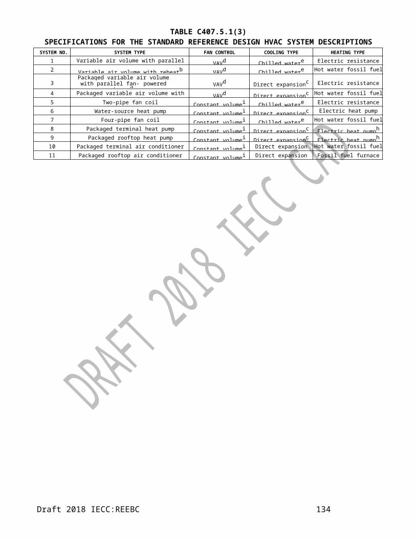
APPENDIX RASOLAR-READY PROVISIONS—DETACHED
ONE- AND TWO-FAMILY DWELLINGS AND TOWNHOUSES
SECTION RA101 SCOPE
RA101.1 General. These provisions shall be applicable for new construction.
SECTION RA102 GENERAL DEFINITION
SOLAR-READY ZONE. 2018 IECC shall apply.
SECTION RA103 SOLAR-READY ZONE
RA103.1 General. New detached one- and two-family dwellings, and townhouses with not less than 55.74 m² (600 square feet) of roof area oriented between 110 degrees and 270 degrees of true north shall comply with Sections RA103.2 through RA103.8.
Exceptions:1. New residential buildings with a permanently installed on-site renewable energy system.2. A building with a solar-ready zone that is shaded for more than 70 percent of daylight hours annually.
RA103.2 Construction document requirements for solar- ready zone. 2018 IECC shall apply.
RA103.3 Solar-ready zone area.
The total solar-ready zone area shall be not less than 27.87 m² (300 square feet) exclusive of mandatory access or set back areas as required by the International Fire Code. New townhouses three stories or less in height above grade plane and with a total floor area less than or equal to 185.8 m² (2,000 square feet) per dwelling shall have a solar-ready zone area of not less than 13.94 m² (150 square
feet). The solar-ready zone shall be composed of areas not less than 1524 mm (5 feet) in width and not less than 7.44 m² (80 square feet) exclusive of access or set back areas as required by the International Fire Code.RA103.4 Obstructions. 2018 IECC shall apply.RA103.5 Roof load documentation. The structural design loads for roof dead load and roof live load shall be clearly indicated on the construction documents.RA103.6 Interconnection pathway. 2018 IECC shall apply.RA103.7 Electrical service reserved space.2018 IECC shall apply.RA103.8 Construction documentation certificate. 2018 IECC shall apply.
Draft 2018 IECC:REEBC 136

UNITS CONVERSION TABLESI Unit I-P Unit Conversio
n Factor1 COP = 3.412969283 EER 0.2931 EJ = 0.947867299 quad (1015 Btu) 1.0551 g = 15.43209877 grain (1/7000 lb) 0.06481 g = 0.035273369 ounce (mass, avoirdupois) 28.351 g = 0.002204624 lb (avoirdupois, mass) 453.5921 g/kg = 6.993006993 gr/lb 0.1431 g/m3 = 0.058479532 gr/gal 17.11 ha = 2.470966148 acre (43,560 ft²) 0.40471 J = 0.000947817 Btu (International Table) 1055.0561 J = 0.000948452 Btu (thermochemical) 1054.351 J = 0.239005736 calorie (thermochemical) 4.1841 J = 0.737463127 ft·lbf (work) 1.356
1 J/kg = 0.334448161 ft·lbf/lb (specific energy) 2.99
1 J/m² = 8.80551E-05 Btu/ft² (International Table) 11,356.531 J/m3 = 2.68392E-05 Btu/ft3 (International Table) 37,258.951 J/m3 = 3.58787E-06 Btu/gal 278,717.181 kg = 2.20462442 lb (avoirdupois, mass) 0.4535921 kg/(Pa·s·m) = 6.87938E+11 perm inch (permeability at 32°F) 1.45E-121 kg/(Pa·s·m²) = 1747839233
7perm (permeance at 32°F) 5.7214E-
111 kg/m² = 0.204918033 lb/ft² 4.881 kg/m3 = 0.133526466 ounce (avoirdupois) per gallon 7.4891521 kg/m3 = 0.0625 lb/ft3 (density r) 161 kg/m3 = 0.008333333 lb/gallon 1201 kg/s = 7936.507937 lb/h 0.0001261 kg/s = 132.2926313 lb/min 0.0075591 kJ/(kg·K) = 0.238845897 Btu/lb·°F (specific heat cp) 4.1868
1 kJ/kg = 0.429922614 Btu/lb 2.3261 kJ/m3 = 0.471947444 kW/1000 cfm 2.118881 km = 0.62150404 mile 1.6091 km = 0.539956803 mile, nautical 1.8521 km/h = 0.621371192 mile per hour (mph) 1.6093441 kN = 0.224719101 kip (1000 lbf) 4.45
1 kPa = 0.009869233 atmosphere (standard) 101.3251 kPa = 0.01 bar 1001 kPa = 0.295298842 in. of mercury (60°F) 3.38641 kPa = 10 millibar 0.1
Draft 2018 IECC:REEBC 137

1 kPa = 7.518796992 mm of mercury (60°F) 0.1331 kPa = 0.145032632 psi 6.8951 kW = 0.101936799 horsepower (boiler) (33, 470 Btu/h) 9.811 kW = 1.341021859 horsepower (550 ft·lbf/s) 0.7457
1 kW = 3.517411185 lb/h [steam at 212°F (100°C)] 0.28431 kW = 0.284333239 ton, refrigeration (12,000 Btu/h) 3.5171 L = 0.006289308 barrel (42 U.S. gal, petroleum) 1591 L = 0.035314667 ft3 28.3168461 L = 0.264172037 gallon (U.S., 231 in3) 3.7854121 L = 1.056747332 quart (liquid, U.S.) 0.94631 L/(s·m²) = 1.472537182 gpm/ft² 0.67911 L/s = 2.118881993 ft3/min, cfm 0.4719471 L/s = 0.035314669 ft3/s, cfs 28.3168451 L/s = 15.84786054 gpm 0.06311 lx = 0.092903044 footcandle 10.763911 m = 3.280839895 ft 0.30481 m = 1.093613298 yd 0.91441 m/s = 196.8503937 ft/min, fpm 0.005081 m/s = 3.280839895 ft/s, fps 0.30481 m/s = 2.237136465 mile per hour (mph) 0.4471 m² = 10.76391505 ft² 0.0929031 m² = 0.107639151 square (100 ft²) 9.29031 m² = 1.196029183 yd2 0.83611 m² = 0.000247104 acre (43,560 ft²) 4046.8731 (m²·K)/W = 6.451612903 clo 0.1551 (m²·K)/W = 5.678269264 ft²·h·°F/Btu (thermal resistance R) 0.176111 m3 = 6.325162699 barrel (42 U.S. gal, petroleum) 0.15809871 m3 = 28.37732765 bushel (dry, U.S.) 0.03523941 m3 = 35.31073446 ft3 0.028321 m3 = 1000 litre 0.0011 m3 = 2113.378531 pint (liquid, U.S.) 4.73E-041 m3 = 1.307873398 yd3 0.76461 Mg = 0.984207408 ton, long (2240 lb) 1.0160461 mg/kg = 1 ppm (by mass) 11 Mg; t (tonne) = 1.10231221 ton, short (2000 lb) 0.9071841 MJ = 0.277777778 kWh 3.61 MJ = 0.009478673 therm (U.S.) 105.51 mL = 0.061022493 in3 (volume) 16.38741 mL = 0.033783784 ounce (liquid, U.S.) 29.61 mL = 0.066666667 tablespoon (approximately) 15
Draft 2018 IECC:REEBC 138

1 mL = 0.2 teaspoon (approximately) 51 mL/J = 55.86592179 gpm/ton refrigeration 0.01791 mL/s = 0.952380952 gph 1.051 mL/s = 3.661434477 in3/min (SCIM) 0.2731171 mm = 0.00328084 ft 304.81 mm = 0.039370079 inch 25.41 mm/m = 1.200480192 in/100 ft, thermal expansion coefficient 0.8331 mm² = 0.001550003 in2 645.161 mm²/s = 1 centistokes (kinematic viscosity n) 11 mm²/s = 1.07643E-05 ft²/s (kinematic viscosity n) 92,9001 mm3 = 6.1024E-05 in3 (section modulus) 16,3871 mm4 = 2.40251E-06 in4 (section moment) 416,2311 mN·m = 0.008849558 in·lbf (torque or moment) 113
1 mN·m = 0.141643059 ounce inch (torque, moment) 7.061 MPa = 0.145032632 kip/in2 (ksi) 6.8951 mPa = 0.007518797 micron (mm) of mercury (60°F) 1331 mPa·s = 1 centipoise (dynamic viscosity m) 11 mPa·s = 2.418964683 lb/ft·h (dynamic viscosity m) 0.41341 mPa·s = 0.000671141 lb/ft·s (dynamic viscosity m) 14901 N = 100000 dyne 1.00E-051 N = 0.101936799 kilopond (kg force) 9.811 N = 3.597122302 ounce (force or thrust) 0.2781 N = 0.224808924 lbf (force or thrust) 4.448222
1 N/m = 0.06852178 lbf/ft (uniform load) 14.5939
1 N·m = 0.737562121 ft·lbf (torque or moment) 1.355818
1 Pa = 10 dyne/cm² 0.11 Pa = 0.00033456 ft of water 29891 Pa = 0.004018647 in. of water (60°F) 248.841 Pa = 0.102040816 mm of water (60°F) 9.81 Pa = 0.020876827 lbf/ft² 47.9
1 Pa = 0.007518797 torr (1 mm Hg at 0°C) 1331 Pa/m = 0.01019368 ft of water per 100 ft pipe 98.11 Pa·s = 0.020885434 lbf·s/ft² (dynamic viscosity m) 47.88026
1 W = 3.412141286 Btu/h 0.29307111 W = 0.022747642 EDR hot water (150 Btu/h) 43.96061 W = 0.014217256 EDR steam (240 Btu/h) 70.337061 W = 44.24778761 ft·lbf/min (power) 0.0226
1 W/(m·K) = 0.577789205 Btu·ft/h·ft²·°F 1.7307351 W/(m·K) = 6.933471263 Btu·in/h·ft²·°F (thermal conductivity k) . 0.14422791 W/(m²·K) = 0.176110194 Btu/h·ft²·°F (overall heat transfer coefficient U) 5.678263
Draft 2018 IECC:REEBC 139

1 W/m² = 0.316998305 Btu/h·ft² 3.1545911 W/m² = 0.017196905 met 58.151 W/m² = 0.092936803 watt per square foot 10.76
Draft 2018 IECC:REEBC 140