Embed Size (px)
Citation preview

CARGOXRT 8-57 Ma
Xtreme Rugged Technology With Ultra Body TM
TM
Assembly InstructIons
1. 3/4” Wrenches (2)2. 13/16” Socket
5. #2 & #3 Phillips Screwdrivers
6. Torque Wrench7. Cordless Drill
TOOLS REQUIRED3. 7/16” Wrench4. 7/8” Wrench
8. T-27 Torx Drive
650-70006-01 All material copyright © 2015 FLOE International, Inc. Unauthorized reproduction is strictly prohibited. Specifications subject to change without notice. 4/10/15rev 4/19

1. Bed & frame 150-01557-01
(wired w/side, clearance, tail lights) ASSEMBLED
2. Axle & hubs ASSEMBLED 550-07277-00
3. Tongue ASSEMBLED (WITH WIRE FISH) 150-01556-01
4. Tongue clamp ASSEMBLED 150-01558-00
5. Limiter strap ASSEMBLED 149-01702-01
6. Tongue jack ASSEMBLED 551-09901-00
7. Tailgate ramp ASSEMBLED 149-00523-01
8. Fenders (2) 005-55810-00
9. Tires (2) 550-00007-00
10. Tailgate ramp latch brackets (2) 005-70022-00
11. Corner supports (2) PS: 150-70003-00 DS: 150-70004-00
12. Teflon isolation strips (2) 005-05910-00
13. Grommet 003-40000-00
14. License plate bracket 008-83207-00
15. Shrinkwrapped hardware card (not shown) 001-70026-01
1
2
3
4
5
6
7
8
8
9
9
10
10
11
11
1212
14
2
13

1. Bed & frame 150-01557-01
(wired w/side, clearance, tail lights) ASSEMBLED
2. Axle & hubs ASSEMBLED 550-07277-00
3. Tongue ASSEMBLED (WITH WIRE FISH) 150-01556-01
4. Tongue clamp ASSEMBLED 150-01558-00
5. Limiter strap ASSEMBLED 149-01702-01
6. Tongue jack ASSEMBLED 551-09901-00
7. Tailgate ramp ASSEMBLED 149-00523-01
8. Fenders (2) 005-55810-00
9. Tires (2) 550-00007-00
10. Tailgate ramp latch brackets (2) 005-70022-00
11. Corner supports (2) PS: 150-70003-00 DS: 150-70004-00
12. Teflon isolation strips (2) 005-05910-00
13. Grommet 003-40000-00
14. License plate bracket 008-83207-00
15. Shrinkwrapped hardware card (not shown) 001-70026-01
CargoMax Assembly - Step 1ASSEMBLING THE AXLES & TIRES - PART ONE
1. Locate the axle isolation strips packed in the assembly components kit.2. Place an isolation strip on the two inside surfaces of the axle mount as shown in FIG. 1A.
TIP: Tape will aid in holding the strips in place.
3. Place the trailer frame on the axle mounts, aligning the holes in the axle mount with the front two holes in the frame. Note: the orientation of the torsion arms in FIG. 1B.4. Next, insert (2) 1/2-13 x 3-1/4” bolts through the bottom holes on the fender support brackets as shown in FIG. 1B. 5. Fasten with (2) flat washers and (2) nylock nuts. Make sure that the axle mount, teflon strip, and axle beam are tight together with no gap before tightening.
Torque to 80 FT/LBS.3

Cargo Max Assembly - Step 2ASSEMBLING THE AXLES & TIRES - PART TWO
1. Attach (1) tire w/rim to each axle hub w/valve stem toward the outside of the trailer frame (see FIG. 2). 2. Secure with (5) 1/2-20 lug nuts per rim. 3. Start all lug nuts by hand to prevent cross threading with the beveled side of the nut toward the wheel – and to ensure proper nut to rim contact. 4. Tighten the lug nuts in sequence (see FIG. 3) in stages. • For steel rims – tighten to 50-75 ft/lbs. • For aluminum rims – tighten to 90-120 ft/lbs.
Inflate tires to 80 PSI. maximum.
4
LUG NUTS ON NEW WHEELS MUST BE RE-TORQUED AFTER THE FIRST 10-25 AND 50 DRIVING MILES. CHECK PERIODICALLY THEREAFTER.THIS SHOULD BE DONE AS CLAMPING LOADS CAN CHANGE FOLLOWING THE INITIAL INSTALLATION DUE TO THE METAL COMPRESSION/ELONGATION OR THERMAL STRESSES AFFECTING THE WHEELS AS THEY ARE BREAKING IN, AS WELL AS TO VERIFY THE ACCURACY OF THE ORIGINAL INSTALLATION.
5
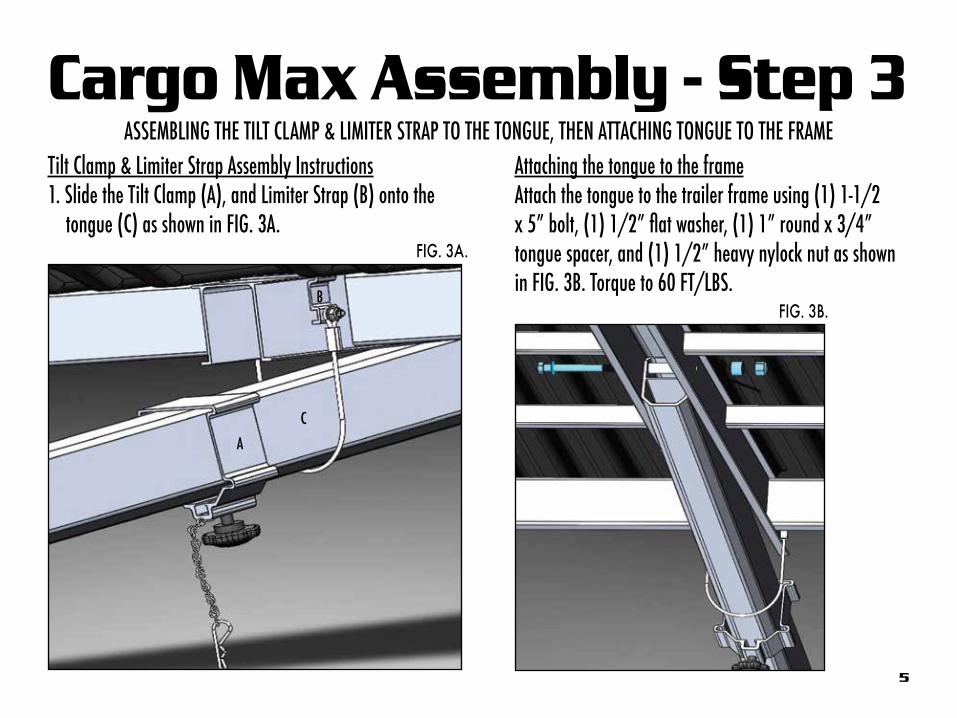
Cargo Max Assembly - Step 3ASSEMBLING THE TILT CLAMP & LIMITER STRAP TO THE TONGUE, THEN ATTACHING TONGUE TO THE FRAME
Attaching the tongue to the frameAttach the tongue to the trailer frame using (1) 1-1/2 x 5” bolt, (1) 1/2” flat washer, (1) 1” round x 3/4” tongue spacer, and (1) 1/2” heavy nylock nut as shown in FIG. 3B. Torque to 60 FT/LBS.
Tilt Clamp & Limiter Strap Assembly Instructions1. Slide the Tilt Clamp (A), and Limiter Strap (B) onto the tongue (C) as shown in FIG. 3A.
A
B
C
FIG. 3B.
FIG. 3A.

6
Cargo Max Assembly - Step 4ELECTRICAL ASSEMBLY
The majority of the wiring is already pre-installed within the frame. The following steps outline how to run the last of the wiring through the tongue using the pre-installed “wire fish”.
1. Attach the flat four prong end of the wire harness to the fish at the rear end of the tongue under the trailer.
2. Locate the end of the wire fish on the coupler end of the tongue and pull the flat plug up through the hole until the strain relief is just inside the grommet hole, and place the grommet over the wire harness and insert into the hole in the tongue with the slit toward the trailer.
HINT: Wetting the grommet with water will make for easier installation.
WARNING! DO NOT OVER-PULL!

7
Cargo Max Assembly - Step 5
Attach the rear corner supports by tipping the top end of the trailer bed in – and sliding it under the upper lip of the trailer bed and inserting the lower tab into the rear frame tube, mak-ing sure that the lip of the bed inserts into the channel of the supports as shown in FIG 5A. • Fasten the bottom using (4) 1/4 x 1” bolts and (4) 1/4” flat washers. See FIG 5B.
Torque to 2 FT/LBS (24 IN/LBS). NOTE: There is a corner riser on each side of the bed – one on the driver’s side and one on the passenger’s side.
ASSEMBLING CORNER RISERS
1/4” FLAT WASHERS
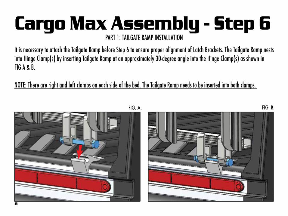
Cargo Max Assembly - Step 6PART 1: TAILGATE RAMP INSTALLATION
It is necessary to attach the Tailgate Ramp before Step 6 to ensure proper alignment of Latch Brackets. The Tailgate Ramp nests into Hinge Clamp(s) by inserting Tailgate Ramp at an approximately 30-degree angle into the Hinge Clamp(s) as shown in FIG A & B.
NOTE: There are right and left clamps on each side of the bed. The Tailgate Ramp needs to be inserted into both clamps.
8
FIG. A. FIG. B.
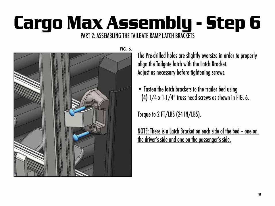
Cargo Max Assembly - Step 6PART 2: ASSEMBLING THE TAILGATE RAMP LATCH BRACKETS
FIG. 6.
The Pre-drilled holes are slightly oversize in order to properly align the Tailgate latch with the Latch Bracket. Adjust as necessary before tightening screws.
• Fasten the latch brackets to the trailer bed using (4) 1/4 x 1-1/4” truss head screws as shown in FIG. 6.
Torque to 2 FT/LBS (24 IN/LBS).
NOTE: There is a Latch Bracket on each side of the bed – one on the driver’s side and one on the passenger’s side.
9
10
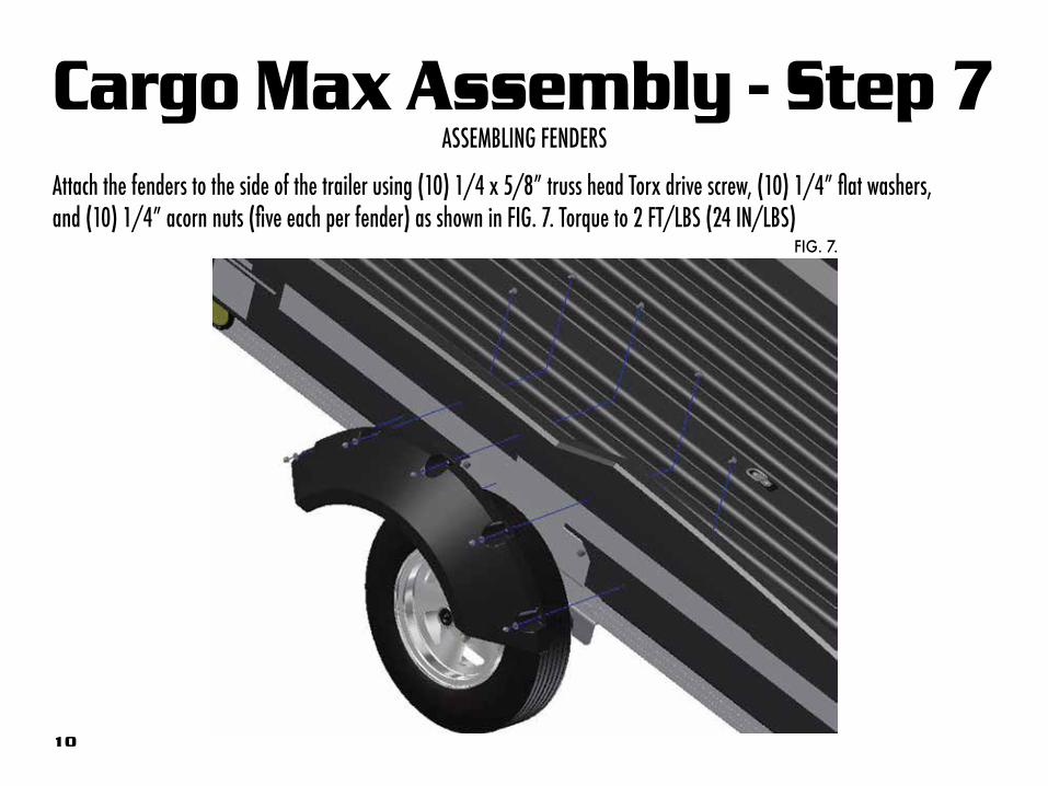
Cargo Max Assembly - Step 7ASSEMBLING FENDERS
Attach the fenders to the side of the trailer using (10) 1/4 x 5/8” truss head Torx drive screw, (10) 1/4” flat washers, and (10) 1/4” acorn nuts (five each per fender) as shown in FIG. 7. Torque to 2 FT/LBS (24 IN/LBS)
FIG. 7.

Cargo Max Assembly - Step 8TONGUE JACK ASSEMBLY
Attach the Tongue Jack to the driver’s side of the tongue using (4) 3/8 x 3-3/4” bolts and (4) 3/8 nylock nuts as shown in FIG. 8A & 8B. Torque to 35 FT/LBS
11
FIG. 8A. FIG. 8B.

Cargo Max Assembly - Step 91. Attach the license plate bracket to the trailer frame using the (2) #10 x ¾” SS self-drilling, self-tapping Phillips screws & (2) fender washers located in the components kit. 2. Locate the bracket 5-1/8” from the inside of the driver’s side axle beam on the first cross member in from the rear (see FIG. 9A & 9B).
FIG. 9A.
ASSEMBLING THE LICENSE PLATE BRACKET*
FIG. 9B.
*May not be needed in states that do not require a license plate on a utility trailer.
#10 X 3/4” SS SCREWS & FENDER WASHERS
#10 X 3/4” SS SCREWS
FENDER WASH-