Embed Size (px)
Citation preview

School of Medicine DIVISION OF MEDICAL PHYSICS
© Copyright, Andrew Davies/The University of Leeds, 2012 Do not reproduce this material without permission
Cardiac X-ray Imaging
Andrew Davies Lecturer in Medical Imaging Division of Medical Physics

Contents
1. X-ray imaging fundamentals
2. X-rays cardiac imaging and the cardiac catheterisation laboratory
3. Characteristics of cardiac X-ray images
4. Example image sequences
5. X-ray dose
6. Summary
7. Bibliography

Why image with X-rays?
X-ray imaging can be used to detect soft tissue abnormalities, image bone, and with the use of contrast agents image the cadiovascular, GI and other internal structures.
It can also be used to visualise devices within the body as they are manipulated during interventions.
In cardiac imaging X-ray imaging plays a key role in both the diagnosis and treatment of coronary heart disease, and other cardiac conditions.

X-RAY PRODUCTION

Producing X-rays
X-rays are produced by colliding electrons into a metal target in an evacuated X-ray tube.
Electrons are produced by passing a current through a filament, heating the filament, resulting in electron emission.
The electrons are accelerated towards a metal target anode by the application of a potential difference typically 40 – 120 kV for cardiac imaging.
Anode
Filament coil & focussing cup
Cathode
+ -
e-
X-ray photons

Producing X-rays
Interaction between the electrons and the target produce X-rays as Bremsstrahlung and characteristic radiation.
A polyenergetic radiation beam is produced.
An X-ray generator is responsible for producing the electrical supply to the X-ray tube.
X-ray production is very inefficient (0.9 x 10⁻⁹ZV).
0 10 20 30 40 50 60 70 80 90 1000
2
4
6
8
10
12x 10
4
Energy (keV)
N p
hoto
ns p
er m
m2
per m
As
50 kVp
70 kVp
90 kVp
Tungsten anode X-ray tube output with
3.5 mm Al inherent filtration

X-RAY INTERACTIONS

X-ray interactions with matter
1. Photoelectric Absorption An X-ray photon interacts with an inner electron of an atom, transferring all of its energy to the electron.
The electron is ejected from the atom and the electron hole is normally filled by a series of electron cascades from outer shell electrons, resulting in auger electron and characteristic photon emissions. The X-ray photon is effectively removed from the beam.
Chance of photoelectric absorption proportional to (Z/Ep)3.
Incident X-ray photon
Ejected electron
Characteristic X-ray and/or Auger electron

X-ray interactions with matter
2. Compton (Incoherent) Scatter An X-ray photon interacts with a loosely bound or free electron, transferring part of its energy to the electron.
The X-ray photon is deflected, but is not removed from the beam.
Scattered X-ray photons can: • further interact with the patient, or
• escape the patient and interact with other objects such as the X-ray image receptor (degrading image quality) or members of staff.
Incident X-ray photon
Ejected electron

IMAGE FORMATION

Image formation in
tens
ity
distance
Modern X-ray image receptors are highly efficient solid state (“flat panel”) devices.
X-rays
Polished Al coating
CsI scintillator converts x-ray photons to light
a-Si TFT photodiode array

Projection images
X-ray images are radiographic shadowgrams- three dimensional objects are projected onto a two dimensional image.

X-RAY CARDIAC IMAGING AND THE CATH LAB

The cath lab
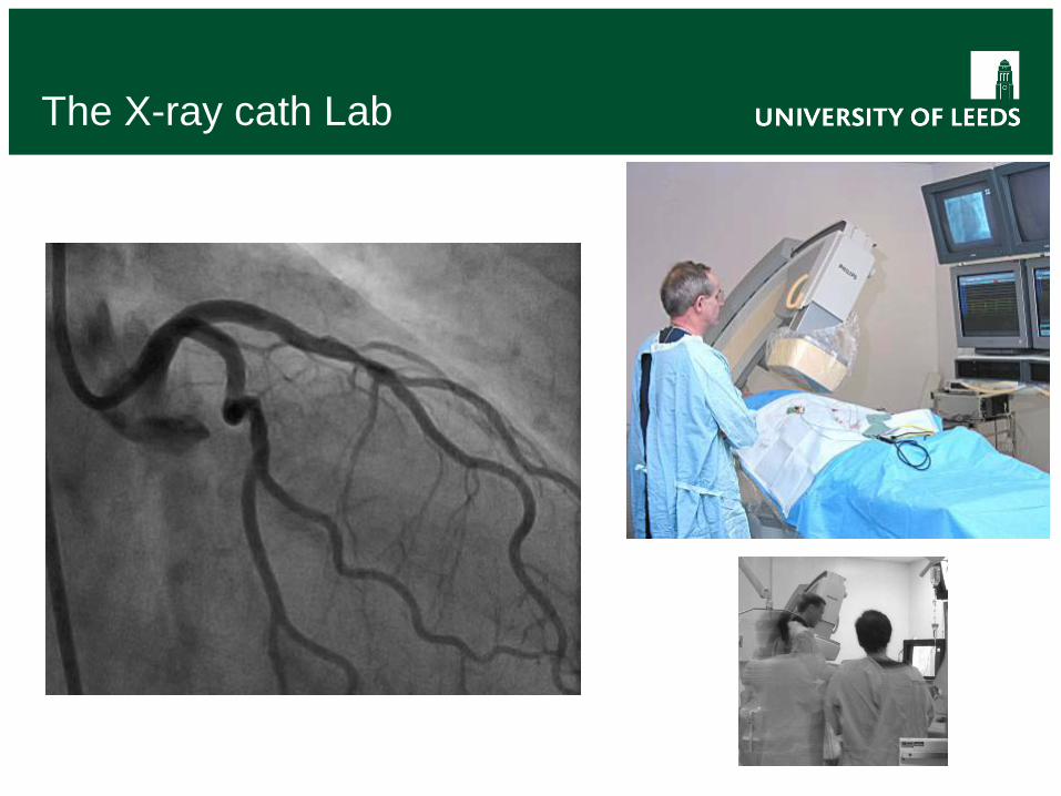
The X-ray cath Lab

Coronary X-ray image sequences
Feature Typical Optional Temporal resolution 15 x 5 ms pulses per
second 30 fps also common clinically, but both higher and lower frame rates possible
Spatial resolution 1024 x 1024 pixels 20 x 20 cm receptor area (200 µm pixel pitch; 100 µm effective pixel size in object plane)
Specialist image receptors can have smaller pixel pitch
Imaging mode Fluoroscopy & acquisition User selectable Field of view 25, 20 & 15 cm C-arm motion ±45° C-C, ±120° Lat
18° - 25°/s motorised motion

EXAMPLE IMAGES

Percutaneous Coronary Intervention
Blood has a very similar linear attenuation co-efficient to soft tissue, and therefore is very difficult to directly discriminate using X-ray imaging.
Blood is therefore temporarily replaced by an iodinated contrast medium with a much greater attenuation than blood for imaging.
A catheter is inserted into radial or femoral artery and advanced over the aortic arch to the aortic root. It is then selectively engaged with the ostium of the right or left coronary artery, allowing the injection of contrast medium or placement of interventional devices into the artery.

Stenting
A stent is a metal mesh support structure placed in the artery to reduce the rate of restenosis.
The stent is positioned under fluoroscopic guidance…
… and inflated to expand the stent. The balloon is then withdrawn.

Post intervention angio
Post intervention angiograms are then acquired in order to confirm proper deployment, and restoration of vessel lumen.
More than one stent can be placed in the same artery, or further arteries treated as necessary.

Fluoroscopy (EP)
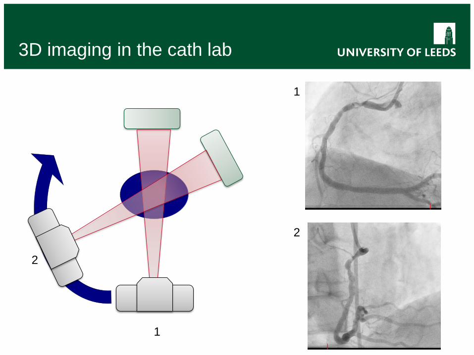
3D imaging in the cath lab
1
2
1
2

3D model

Radiation Dose
Dose rates on the image receptor dictate the level of noise within the image (noise ∝ √dose).
X-rays have two main detrimental effects to humans: • Deterministic effects, mainly damage to the skin
• Threshold (2 Gy) before any effect seen
• Severity increases with dose
• Stochastic effects, fatal cancer and birth defects
• Severity not affected by dose
• Likelihood of occurrence is related to dose

Radiographic imaging of the heart
Feature Notes High temporal and spatial resolution possible
Limited in humans to acceptable patient radiation dose levels
Projection geometry Projection information does not resolve 3D information directly, but requires less X-ray dose than cardiac CT.
Anatomy: accurate assessment of morphology
Aterial, veneous and ventrical lumen all possible. Morphological information of vessel lumen stenotic severity does not necessarily correlate with functional severity.
Function: assessment of blood flow / perfusion
Blood flow is normally measured via another device (e.g. intra-arterial doppler). Has been demonstrated directly from imaging, but is not routine (or straightforward). Assessment of perfusion currently rudimentary, but remains an area of active research.

Perfusion assessment
Pre intervention Post intervention

Bibliography
Radiological Physics • Bushberg JT, Siebert JA, Leidholdt E, Boone JA. 2012. The Essential
Physics of Medical Imaging. 3rd Edition. Lippincott Williams & Wilkins.
• Huda W. 2009. Review of Radiological Physics. 3rd Edition. Lippincott Williams and Wilkins.
Clinical Applications • Lanzer P (Ed.) 2012. Catheter Based Cardiovascular Interventions: a
Knowledge based approach. 2012 Edition. Springer.
Questions • [email protected]