Embed Size (px)
Citation preview

Interlocking Stabilised Soil Block
CONSTRUCTION HANDBOOK Double Interlocking Rectangular Blocks for House Construction
_ _ _ _ Complete Version _ _ _ _
By: Dan Andabati
(BEng Civil and Building Engineering)
May 2010
ISSB

Good Earth Trust ISSB Construction Handbook May 2010 i
CONTENTS
A. PREFACE .................................................................................................... ii
B. DISCLAIMER .............................................................................................. iii
C. ACKNOWLEDGEMENTS ................................................................................ iv
D. INTRODUCTION............................................................................................ 1
D.1 Technology Overview .................................................................................................................... 1
D.2 Building Plans................................................................................................................................. 2
E. MASONRY PRINCIPLES .................................................................................. 4
E.2 Mortar .............................................................................................................................................. 5
E.3 Bonding Patterns and Coursing .................................................................................................... 6
E.4 ISSB Parts ...................................................................................................................................... 6
F. SUBSTRUCTURE .......................................................................................... 7
F.1 Introduction ..................................................................................................................................... 7
F.2 Site Clearance ................................................................................................................................ 7
F.3 Setting-out ....................................................................................................................................... 8
F.4 Excavations..................................................................................................................................... 9
F.5 Foundation Strip ............................................................................................................................. 9
F.6 Plinth Wall ....................................................................................................................................... 9
F.7 Ground Slab ...................................................................................................................................10
G. SUPERSTRUCTURE WALLING ....................................................................... 11
G.1 Introduction....................................................................................................................................11
G.2 the “L” Junction .............................................................................................................................11
G.3 the “T” Junction .............................................................................................................................12
G.4 the “X” Junction .............................................................................................................................13
G.5 Stopped Ends, Door and Window Openings ..............................................................................14
G.6 Raising the Walls ..........................................................................................................................14
G.7 Ring Beam / Bond Beam and Formwork ....................................................................................15
G.8 Finishing the Wall .........................................................................................................................16
H. ROOFING .................................................................................................. 17
H.1 Introduction ....................................................................................................................................17
H.2 Roof Structure and Connections .................................................................................................17
H.3 Roof Cover and Rainwater Harvesting .......................................................................................18
I. FINISHES ................................................................................................... 19
I.1 Introduction .....................................................................................................................................19
I.2 Rendering / Plastering ....................................................................................................................19
I.3 Cement Shurry ................................................................................................................................20
I.4 Paints ...............................................................................................................................................20
J. INSTALLING TECHNICAL SYSTEMS ................................................................. 21
J.1 Introduction .....................................................................................................................................21
J.2 Electricity ........................................................................................................................................21
J.3 Plumbing .........................................................................................................................................21
K. SCAFFOLDING / PLATFORMS ........................................................................ 23
L. FURTHER READING ..................................................................................... 25
M. APPENDIX ................................................................................................ 26
M.1 Some Design Considerations for a low-cost house ...................................................................26
M.2 Typical Low-Cost Home Plans ....................................................................................................27
M.3 Sample Building of Costs .............................................................................................................29

Good Earth Trust ISSB Construction Handbook May 2010 ii
A. PREFACE
Compressed earth block technology (often referred to as ISSB - interlocking stabilized soil block –
in Uganda, courtesy of Dr. Moses Musaazi of Makerere University’s Appropriate Technology
Centre) provides a renewed, economically and socially as well as environmentally relevant
response to building construction across all walks of life. This simple building material, made from
a mixture of marrum (lateritic soil) with a small proportion of cement (usually between 5 – 10 % by
volume) and compressed in a suitable mould under optimum moisture condition, has adequate
capacity for adaptation to a broad spectrum of factors – physical, ecological, social, economic, and
technical – which influence the production of the built environment. ISSB has proven success for a
wide range of applications from simple non-load bearing walling to framed structures.
Whereas the ISSB building technology is firmly backed by scientific body of knowledge, its huge
potential for local production and use to ably generate a wide range of jobs from quarrying to block-
making, and from builder to entrepreneur, and its foreign currency and energy saving abilities have
not been adequately exploited in Uganda and greater East Africa where the technology has been
in use for over twenty years now. This is partly attributed to the lack of artisan knowledge and
skills, and it is against this background that this Construction Guide has been prepared by Good
Earth Trust primarily targeting the informal and small-scale formal builders in the region; larger
building companies will also find it useful.
The main objective of this Handbook is to provide trainees and potential users of the ISSB
technology with simple but sufficiently detailed and well illustrated guidelines for easy application of
the technology on any construction project without the need for further information. Detailed
sketches and lists of relevant tools/equipment which may be manufactured or available locally are
provided. In the few instances where the available information is not sufficient, the reader may
obtain additional guidelines from a qualified source.

Good Earth Trust ISSB Construction Handbook May 2010 iii
B. DISCLAIMER
The construction techniques presented here are derived from the best practices in Uganda where
the initial target audience is based. It is also assumed that the potential users of this Manual are
trained persons who already are familiar with conventional building practices. Therefore, Good
Earth Trust reserves the right not to be responsible for the topicality, correctness, completeness or
quality of the information provided in this Handbook. Liability claims regarding damage caused by
the use of any information provided, including any kind of information which is incomplete or
incorrect, will thus be rejected. Information in this document might be extended, changed or partly
or completely deleted without prior notice. Views expressed in this Handbook do not necessarily
reflect those of the Good Earth Trust or its management. Excerpts may be reproduced without
authorization, on condition that the source is indicated.

Good Earth Trust ISSB Construction Handbook May 2010 iv
C. ACKNOWLEDGEMENTS
Thanks to the Good Earth Trust teams in Uganda, Kenya and the UK for moral support and
facilitation – Gordon Browne of Southampton Solent University, also GET Trustee read through the
Draft document and offered such incredible advice and comments that have helped in preparing
the final version. Credit also goes to Dr. Moses Musaazi of Makerere University and Technology
for Tomorrow (T4T) team (Uganda) for the invaluable expertise in compressed earth technology,
which underpins most of the discussions presented in this book. Last (but not least), thanks to
Makiga Engineering Services Ltd. (Kenya) – the manufacturer of the block press described in this
Construction Guide.
Good Earth Trust ISSB Construction Handbook May 2010 1
D. INTRODUCTION
D.1 Technology Overview
Compressed earth / ISSB building technology has not only achieved a level of industrial potential
with production methods suited to the formal construction sector, but also the ability to remain on
the scale of craft production relevant to informal sector application. This implies that compressed
earth building technology can be used in rural as well as urban contexts and can meet very widely
differing needs, means and objectives. The various dimensions of earth blocks available on the
market also lend themselves to great flexibility of use in different building solutions, as load-bearing
masonry or as in-fill.
However, compressed earth technology presents with some constraints that can pose significant
challenges to its application if not adequately resolved. For instance, the quality of compressed
earth blocks greatly depends on good soil selection and preparation of constituents, and on the
correct choice and use of the production equipment.
On the other hand, the wide-range benefits and potential of compressed earth technology speak
for themselves and yet thus far, its profile is very low in Uganda and rest of East Africa. The full
scope of benefits offered by this technology includes:
Environmental – The blocks are cured rather than fired, which eliminates the need for
firewood and charcoal. This helps to reduce the destruction of fragile ecosystems such as
wetlands and forests associated with traditional methods of producing of fired bricks – thus
energy saving and reduction of greenhouse gases.
Economy and Versatility – Construction costs are considerably less than building with fired
bricks (traditional method) due to less mortar requirement, on-site production of blocks
using local soil thereby minimizing bulk material transportation (costs), the interlocking
feature speeds-up construction and results in stronger walls. The blocks are also suitable
for use in construction of water and sanitation facilities such as latrines and water storage
tanks at dramatically reduced cost.
Accessibility and Sustainability – The block presses are readily available and affordable to
small informal builders. These machines are robust, portable and require only basic
maintenance skills that are readily transferable.
Community Empowerment and Livelihoods – It offers pro-active and self-help opportunities
to low-cost, community-level shelter provision: a simple technology requiring lower-level
artisanal skills; thus the potential to train and use local construction manpower will reduce
the overall cost of house delivery. The techniques are also labour-intensive with the
potential to generate local skills, employment, and income.
Thus, ISSBs should be produced while carefully considering the following points (for best results):

Good Earth Trust ISSB Construction Handbook May 2010 2
Testing the soil and adoption of optimum proportions of soil, stabiliser (usually ordinary
Portland cement (OPC)), and water, taking into consideration the characteristics of the soil
in question.
Careful and thorough mixing of the various components (soil, cement and water). Soil and
cement are first mixed dry to a homogeneous mass then water is added in small amounts
and mixed in until it is uniformly distributed throughout the soil-cement mass up to a point
where a lump squeezed hard in the hand just sticks together into a ball (optimum moisture
content).
Application of an adequate compaction pressure to the mixture in order to obtain dense and
strong building blocks with well-shaped surfaces and edges – by the correct use of the
block press as detailed in its Operational Manual.
Curing the blocks sufficiently (by keeping them under cover and regularly sprinkling with
water) for at least seven days before usage to minimise the risk of damage to the blocks
and cracks in the finished structure as well as give an excellent finish to the wall. Obtaining
a smooth block surface can further permit their use without rendering or with a minimum
use of rendering materials if required.
The Kenya Standard Specification (KS 02-1070: 1993) and Draft Uganda Standard (DUS 849:
2009) provide the following (minimum) physical characteristics of cement stabilized soil blocks
necessary for good building construction:
Dry Compressive Strength of blocks at 28 days ≥ 2.5 N/mm2;
Wet Compressive Strength of blocks at 28 days ≥ 1.5 N/mm2;
Rapture Strength of blocks at 28 days ≥ 0.5 N/mm2;
Water Absorption of blocks ≤ 15 per cent of the original [dry] mass;
[Dry] Density of blocks ≥ 1600 Kg/m3;
Weathering loss of mass ≤ 15 per cent of the original [dry] mass;
Shrinkage cracks ≤ 0.5 mm wide and ≤ 50 percent of the parallel block dimension; and
Visibly free of broken edges, honeycombing, and other defects that would impair quality.
Note that determinations of the above parameters are beyond the scope of this Manual therefore
the reader is advised to refer to standard documents for detailed procedures.
D.2 Building Plans
All building projects must have relevant drawings (of sorts). As this Handbook is based on building
construction using the straight double interlocking stabilized soil block, a simple 2-bedroom
building plan is provided below for illustrations (Fig. D.2b). Note that the building dimensions are
ISSB-specific (see Fig. D.2a below for the block dimensions). Some planning aspects and typical
architectural models of low-cost homes are also included in the Appendix to this Handbook.

Good Earth Trust ISSB Construction Handbook May 2010 3
Fig D.2a ISSB Dimensions
STRAIGHT DOUBLE INTERLOCKING BLOCK
Format Size: 290 x 140 x 115 mm
Coordinating Dimensions: 265 x 140 x 100 mm
(Order: Length x Breadth x Height)
Courtesy of Makiga Engineering Services-2009
115 mm 100 mm
265 mm 140 mm
290 mm
SIDE
PLAN
END
Fig D.2b 2-Bedroom House Plan
REAR
SID
E (
2)
FRONT
SID
E (
1)
STORE
BEDROOM
PORCH
BEDROOM
LIVING ROOM
7.82 m
6.7
5 m

Good Earth Trust ISSB Construction Handbook May 2010 4
E. MASONRY PRINCIPLES
E.1 Introduction
Tools and Equipment:
Hoe, spade, pick axe, wheelbarrow, axe, rake, machete, bow-saw, pegs & profiles, building line,
claw hammer, long tape measure, steel tape measure, water level, spirit level, wire nails, plumb bob,
sledge hammer, mortar pan, 20L jerry-can, wooden rammer, water reservoir, gauge box, gauge rod,
trowel, building square, metal saw, personal safety gear (overall, boots, helmet, gloves, etc).
These can readily be obtained from the local hardware shops and the specific types and numbers
will depend on the nature of the proposed building project and the number of operatives to be
deployed on the job – depending on the availability and cost of labour at the project site. Note that
block production is separately treated under ISSB Machine Operation Manual, which must be
referred to for detailed guidelines (here, it is assumed the blocks have already been made).
Materials:
Local materials: Sand (both coarse and fine if available), 20mm stone aggregate (ballast), water
(clean), hardcore (Stone boulders), soil (marrum), timber boards (275mm x 25mm), 100mm
diameter eucalyptus poles.
Hardware materials: Cement, wire mesh, damp proofing material (bituminous felt), 12 mm steel
bars, 6 mm round bars, Door/Window frames, sawn timber, roofing sheets and matching ridges /
valleys, wire nails (assorted sizes), roofing nails, rubber washers, hoop iron, etc.
A compressed earth masonry structure consists of small building blocks placed one on top of the
other following a designated bonding pattern and often bound together with mortar. Note that when
Gauge Box
Bucket
Wheelbarrow
Sand Screen
Fig E.1 Some Masonry Equipment

Good Earth Trust ISSB Construction Handbook May 2010 5
using the narrow ISSB (265 x 140 x 100mm), it is recommended to always use a thin layer of
mortar (approx. 6mm) in every horizontal joint. This improves the bond and cohesion between the
blocks against lateral forces on the wall and facilitates vertical alignment by compensating for any
small variations in dimensions that would cause blocks to rock and tilt under load (prevents
buckling of tall walls).
Thus, the earth blocks form a building system, which has compressive strength and stability
dependent on the interaction of several factors:
The quality of the block itself;
The quality of the mortar used;
The quality of the bonding pattern adopted; and
Overall workmanship – which enhances the interaction or compatibility between the block,
mortar & bonding pattern
ISSB masonry can be used for any kind of structure required by compressive forces such as load-
bearing walls, partitions, pillars, arches, vaults and domes.
E.2 Mortar
A mortar is a mixture of sand with cement (as a binding agent) to which water is added in
controlled amounts. Used in a plastic state, mortar ensures good mechanical bonding between the
blocks making up a wall or other building system. Mortar also allows vertical forces due to the
weight of the weight of the blocks to effectively be transmitted down to the bearing surfaces and
foundations. When freshly mixed, mortar for ISSB construction should be fairly fluid and made from
sand passed through a 6mm screen (Fig E.1). It should display good cohesion and consistency as
well as the capacity to retain water against the suction of the blocks. The mixing water of the
mortar should be clean and surfaces to which mortar is applied should be free of dirt and
moistened so the blocks do not dehydrate the mortar instantly.
In principle, mortar should have mechanical properties which are compatible with that of the
building blocks. Thus, the proportion of cement used should be increased by a factor of 1.5 or 2 to
achieve the same strength as the blocks. Note that too low a strength mortar carries the risk of
water infiltration and eventually deterioration of the masonry. Meanwhile, too high a strength mortar
can cause shrinkage cracks and deterioration of the masonry. Care should always be taken to
prevent the mortar drying out too quickly by sprinkling the wall during hot weather.
For ISSB construction, cement/sand mortars of different mixes are normally used for different
strength requirements. Two types of sand are normally used to achieve good results; these are soft
(plaster/pit) sand with very fine particles and sharp (lake/river) sand having coarse grains. More of
soft sand to sharp sand is used (say 2:1 in a 3-part mortar sand, and 2.5:1.5 in a 4-part mortar
sand) for improved workability and bonding characteristics of mortar. The oversize material in the
sand for mortar must always be removed by sieving as a separate operation, and just enough
mortar to last for a maximum of 1 hour at a time should be mixed.

Good Earth Trust ISSB Construction Handbook May 2010 6
Once the block has been laid, it should be pushed firmly into place – never tap or hit the block as
this could destroy the adherence between the block and the mortar. If required, the joints should be
smoothed as soon as the blocks have been laid using a suitably sized piece of plastic tubing or
wood.
E.3 Bonding Patterns and Coursing
The term ‘bonding pattern’ refers to the way in which the building blocks are arranged, assembled
and therefore bonded together in all directions of a masonry structure. The bonding pattern
determines the position of each block from one course to another and notably prevents vertical
joints occurring one immediately above the other, which would entail the risk of cracks spreading
through the structure. Bonding patterns therefore play an essential part in ensuring the cohesion,
stability and strength of masonry structures built from ISSBs.
‘Coursing’ is the link between the dimensions of the ISSB, the dimensioning of the building and
their architectural representation in plan, elevation, section or detail. Coursing ensures good
project control by enabling correct height management and precise quantitative data to be
obtained. For instance, determining the right number of blocks required and monitoring losses due
to excessive block cutting, as well as determining the exact dimensions of openings in the wall for
doors and windows, the exact position of a ring-beam etc – all this precision will enhance the
quality of the finished structure.
Coursing the working plan (usually ‘first’ and ‘second’ courses) must be done ‘globally’ for the
whole building and not in a fragmented way, which could result in confusion when trying to bring
together the different fragments of the quantified plan.
E.4 ISSB Parts
The ISSB parts are shown in Fig E.4 below. The orientation of the block is as it comes out of the
block press and the various parts are: (1) “top” – the depressed longitudinal bed; (2) “tail” – the
protruded cross-sectional end; (3) “head” – the depressed cross-sectional end; and (4) “bottom” -
the protruded longitudinal bed. For dimensions of the ISSB block, refer to Figure D.2a above.
Fig E.4 ISSB Parts (side elevation)
(1) "Top" (depression)
(4) "Bottom" (protrusion)
(3) "Head" (depression)
(2) "Tail" (protrusion)

Good Earth Trust ISSB Construction Handbook May 2010 7
F. SUBSTRUCTURE
F.1 Introduction
Sub-structure generally includes all the components of a building that bear directly onto the ground
(see Fig F.1 above). The usual sequence of activities for construction is: (1) Site Clearance, (2)
Setting-out, (3) Excavations, (4) Foundation Strip (600mm x 100mm plain concrete), (5)
Foundation Plinth (full-length ISSB wall – 10% cement content), and (6) Ground Slab (usually a
composite structure consisting of 25mm cement/sand screed on 100mm mass over-site concrete
(plain or reinforced) on rubbles or “hardcore” on well compacted formation (ground)). Each
operation is described in more detail hereafter.
Note also that stone foundation in cement mortar (1:4) with 100mm C20 reinforced concrete
topping (2 re-bars) can be used where stones are readily available. This technique is useful where
the slab, not sitting directly on the foundation wall, is constructed after the superstructure walls
have been built.
F.2 Site Clearance
Clear the site of any obstacles and remove the top soil for the footprint to an average depth of 150
mm from the existing ground level. Vegetative soil is not good for use in construction, so remove
and deposit the spoil away from the building area but in a place where it can eventually be used for
gardening purposes.
Fig F.1 Typical Substructure Detail
Stripped ground level
Foundation strip
Plinth wall: ISSB (8-10% cement) header-bond & bedded in 15mm mortar
Ground slab
Finished floor level
Super wall: ISSB (5-8% cement) stretcher-bond & bedded in thin mortar
Back-fill & compact in layers not exceeding 200mm

Good Earth Trust ISSB Construction Handbook May 2010 8
F.3 Setting-out
The building is set-out for excavation of foundation trenches by use of profiles fixed clear of the
trenches by at least 1 m so as not to disturb or bury the profiles in the heap of excavated soil. All
profiles should be established to a fair level (using a water level) and set off the ground by at least
0.5 m (Fig F.3b).
Fig F.3a Setting-out Plan
7 m
6 m
FRONT
REAR
SID
E (
1)
SID
E (
2)
Profiles
Lines/Strings
Keep profiles clear of excavation
(≥1m)
0.6
m
0.6
m
0.6 m
0.6 m
2.7 m
0.7 m
2 m
2.5 m
Fig F.3b Profile Set-up
Peg: 50x50mm timber or 60mm pole sharpened on one end
≤750 mm
Profile: 50x50mm timber or 60mm pole ≥1m long nailed to fair level on pegs
≥500 m
m
Ground level

Good Earth Trust ISSB Construction Handbook May 2010 9
F.4 Excavations
Excavate strip foundation trenches to the required width using the simple hand tools listed above,
to a depth usually determined on site where uniform and stable soil is encountered, but ≥600mm
from the stripped ground. Heap the excavated soil within the building area (but clear of the
trenches) to be eventually used for backfilling. Always ensure that the sides of the trenches are
safe for the operatives – in loose soils, the sides of the excavation need to be adequately
supported. Level the trench bottom and compact with a hand-held rammer and if required, apply
anti-termite treatment to the bottom and sides of the trenches by sprinkling the solution with a
watering jar.
F.5 Foundation Strip
The footing is usually plain concrete of class C15 commonly associated with a volume mix ratio of
1:3:6 (cement: sand: stone aggregate). Use the same gauge box or bucket to measure all the
ingredients including cement and mix concrete on clean platform using clean water; pour 50-100
mm thick in trenches. Compact concrete with a poker vibrator or manually using a wooden tamper
to a fairly level finish and cure by wetting the strip twice daily for at least 3-7 days to allow concrete
to harden reasonably well before constructing the plinth wall
F.6 Plinth Wall
Plinth wall is the block-work that is usually buried in the ground and on which the ground slab or
the superstructure rests. It is therefore the means of permanently fixing a building to the Earth's
surface as such it should be made sufficiently stable to be effective. For this reason, it is
recommended that plinth walls underlying load-bearing walls of low-rise buildings be made of full-
length ISSB block-work mortared in the horizontal joints.
Raise the plinth wall to a height such that the finished floor level is at least 200 mm above the
stripped ground so that storm water cannot run into the house. Backfill the excavated subsoil
around the plinth wall in layers not exceeding 200 mm ensuring that both sides of the walls at any
Fig F.6 Plinth Wall
Backfill & compact in layers ≤ 200mm up to stripped ground level Stripped ground level
Part of plinth wall above stripped ground level ≥150 mm
Foundation concrete
Mortar horizontal joints

Good Earth Trust ISSB Construction Handbook May 2010 10
point are filled up to the same level every time. This ensures balanced earth pressures on either
side of the wall thereby eliminating the risk of buckling or cracks in the plinth during compaction of
the backfill – if the backfilled soil is not moist (especially during very dry weather), sprinkle some water
onto the soil. Compact both layers of soil on either side of the wall at just about the same time (it is
recommended to have at least two people compacting at the same time, one on each side of the wall).
Repeat the backfilling and compacting operations, each time in layers not exceeding 200 mm, up to the
level of the stripped ground. Once done, your foundation is then ready to receive the ground slab.
F.7 Ground Slab
The ground slab is usually a composite load-bearing structure comprising two or more layers of
different materials. The most common detail includes 25 mm cement/sand screed; on 75 mm plain
concrete; on 150 mm stone base (hardcore); on well compacted earth-fill. For economic reasons,
rendering of 600mm high above the finished floor level can be applied to protect the walls from the
abrasive effects of driving rain or water splashing off the ground. Alternatively, where stone
masonry plinth wall bonded in cement/sand mortar (1:4) has been used instead of ISSBs,
rendering can be applied only above the damp proof membrane (DPM). Generally, the ground
around building should be sloped outward to direct run-off water away from the building. Big roof
overhangs should also be deployed to further protect the walls from the effects of driving rain.
In constructing the slab, it is always important to bear in mind the final or finished floor level and
the materials and thicknesses to be used. It is good practice to always mark the various depths of
the flooring materials on all sides of the slab against the corresponding plinth walls before
commencing with the slab construction. These levels should be coordinated with a water level and
always referred to when laying the floor materials. Figure F.7 below shows a typical slab
construction detail and associated weathering or drainage features. Always cure concrete
adequately by pouring water onto the slab at least three times a day (morning, noon, and evening)
for a minimum of seven consecutive days before proceeding to construct the superstructure walls.
Fig F.7 Typical Ground Slab and Drainage Detail
Gro
un
d s
lab
Super-wall & part of plinth wall to be rendered externally to at least 600mm above floor level to be rendered for protection against driving rain & water splashing off the ground
100mm Backfill
150mm Hardcore
25mm Blinding
25mm Screed
Compact back-fill & slope the ground away from the plinth wall to direct run-off water away from the building
75mm Concrete
Finished floor level DPM

Good Earth Trust ISSB Construction Handbook May 2010 11
G. SUPERSTRUCTURE WALLING
G.1 Introduction
Whereas ISSBs are self interlocking, it is recommended that walls be mortared in every course
when using the narrow block (265 x 140 x 100mm). Given the relatively small wall thickness,
mortar improves the bond and cohesion between the blocks against lateral forces on the wall and
facilitates vertical alignment by compensating for any small variations in dimensions that would
cause blocks to rock and tilt under load (prevents buckling of tall walls).
However, for economic reasons and to achieve greater benefits of the interlocks, the mortar should
be limited to just about 6 mm. Note that ISSB vertical joints are not normally mortared and the
blocks should always be laid stretcher half bond (with each course overlying the course below it by
nearly half a block) so as to avoid the vertical joints in adjacent courses coinciding or being too
close to each other.
The blocks are often laid on their bottom face and running tail-wise from a corner towards the
middle of the wall. For the first course, the protrusion is usually removed using a machete (panga
knife) so the blocks can stably bed in mortar; a level base also helps to control the amount of
mortar used at that level. The first course must be carefully set to good level using water and spirit
levels and building lines as subsequent courses will generally base on this level. The overlying
courses can be controlled using a gauge rod, building line and plumb bob and levelling tools to
ensure uniform levels and verticality of the wall. A builder’s square must always be used to check
right angles.
Corners or wall intersections are structurally important sections of walls as they provide the lateral
stability and load carrying capacity of the walls. In ISSB construction, the key principle in laying
blocks is to avoid vertical joints. Five different scenarios of wall intersections or junctions often
encountered in ISSB construction will be considered:
The “L” junction;
The “T” junction;
The “X” junction; and
The stopped end
The following diagrams illustrate how corners and wall intersections are constructed.
G.2 the “L” Junction
These are usually found at the extreme ends of a rectangular shaped house. Note that an ISSB
crossed over the top of another should have the bottom protrusion removed carefully with a
machete prior to laying the block.
Good Earth Trust ISSB Construction Handbook May 2010 12
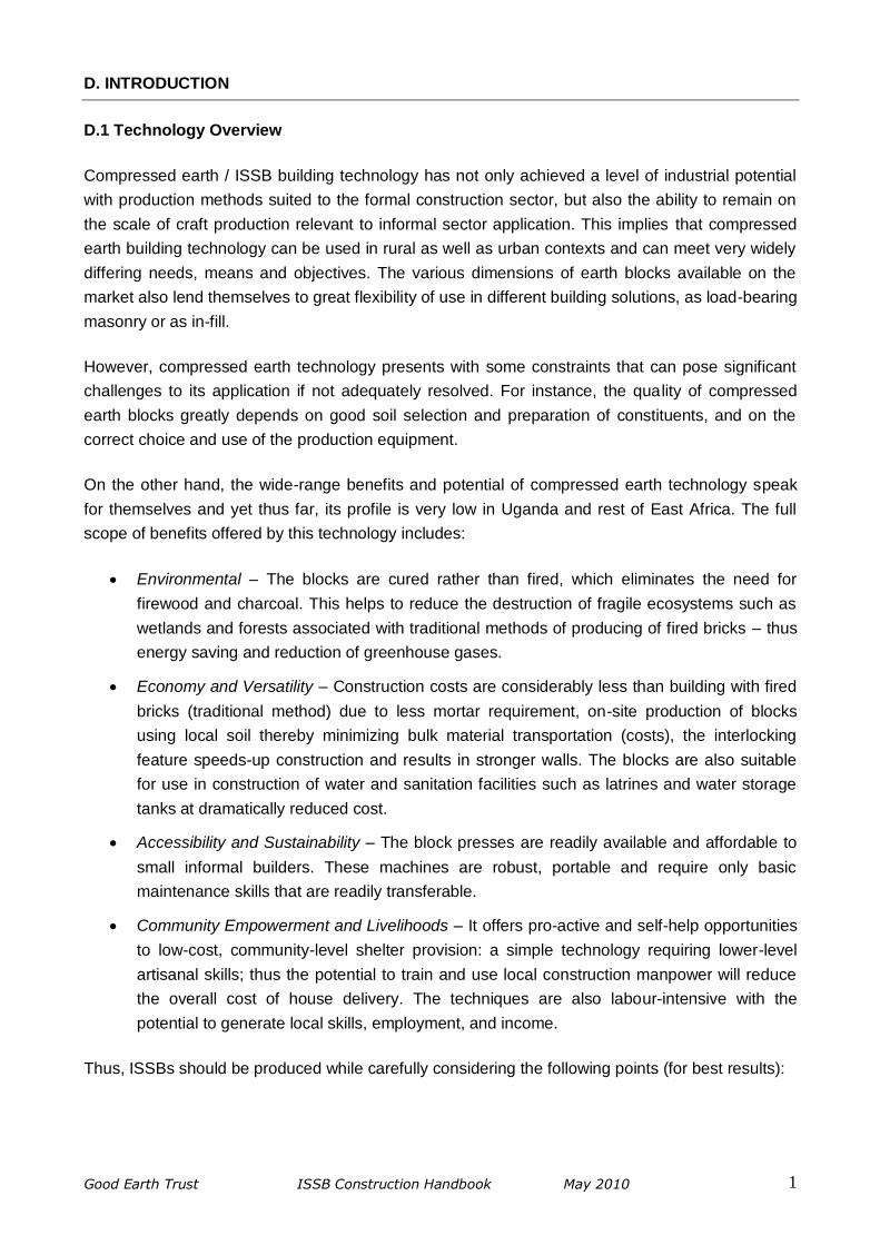
G.3 the “T” Junction
Fig G.2 Typical ISSB ‘L’ Junction
Use mortar here
(b) Even Courses
Use mortar here
(a) Odd Courses 1
st
(c) Elevated Wall
2nd
Mortar on DPC
Trim dotted portions
3rd
5th
4th
6th
7th
8th
3rd
5th
1st
2nd
4th
Mortar
(a) Odd Courses & Wall Elevation
Mortar
70mm
Cut tail
70mm
Cut head Use mortar here
(b) Even Courses & Wall Elevation
Full blocks
Fig G.3a Typical ISSB ‘T’ Junction

Good Earth Trust ISSB Construction Handbook May 2010 13
The “T” is an extension of the “L” corner and must always be made to coincide with a vertical joint
of the running wall. In order to avoid straight joints, the adjoining blocks (i.e. the blocks forming the
cross on the “T” in the running wall must be cut so that the block bond is not interrupted. When
laying corner blocks, always remember to remove portions of the bottom protrusion to
accommodate the corrugations.
A further extension of the “T” junction is a pier, which is a buttress-like section of a very long wall –
usually of more than 3m – commonly found in perimeter walls and large institutional buildings such
as classroom blocks, halls, dormitories, etc. As there are usually no close returns in such walls,
piers are introduced at intervals not exceeding 3m so as to stiffen the walls and enhance their
structural integrity.
G.4 the “X” Junction
(a) Odd Courses
Mortar
(b) Even Courses
Mortar
Maximum 3 meters
Fig G.3b Typical ISSB Pier
Pier Wall
Use mortar here
(b) Even Courses
Tie block
Main wall
Mortar
(a) Odd Courses
Mortar
70mm
Cut head
Mortar
Fig G.4 Typical ISSB ‘X’ Junction
Mortar

Good Earth Trust ISSB Construction Handbook May 2010 14
The “X” or cross Junction is similar to the “T” junction where blocks in the main wall have to be cut
to reduce their lengths so that the established block patterns are not altered to avoid vertical joints.
Note that all four centre blocks in the odd-course are cut to 195mm and they should always tie at
the centre of the cross.
G.5 Stopped Ends, Door and Window Openings
Walls are usually stopped to create openings such as doors and windows. Given that vertical joints
are always staggered for succeeding courses in a wall, cutting of the blocks to create a regular
vertical edge is inevitable. It is recommended that an opening or a stopped end be introduced just
after full blocks in alternate courses. This implies that doors or window frames to be used in ISSB
construction should have breadths in multiples of a unit ISSB length (i.e. 265 mm) so the frames
can fit in place and the blocks can maintain the half-bond.
G.6 Raising the Walls
The entire house should be laid out on the first course including the door openings to ensure that
the blocks tie up above the door lintels. Before continuing with the second course, check that the
base or first course is level and that all corners are square. Once this is completed the blocks of
the door areas should then be removed. Note that the first course is always laid in mortar with the
ISSB top upwards and the bottom protrusion removed as described before. The corners are first
(a) Odd Courses
Fig G.5 Typical ISSB Wall Opening
Cut Cut
Mortar Mortar
(b) Even Courses
1st
Remove dotted
portions
1st
8th
9th
11th
10th
12th
Cut block Cut block
Window Opening in ISSB Wall
Mortar on DPC
Mortar Mortar

Good Earth Trust ISSB Construction Handbook May 2010 15
raised to about five courses high at a time and every corner levelled using a water level. A string is
then fixed along a given course and blocks are laid from the corners towards the middle of the wall.
Note that if the layout on the first course was correct, the blocks should fit into the wall without
trimming.
G.7 Ring Beam / Bond Beam and Formwork
The bond beam (commonly referred to as “ring beam”) is an important part of the structure as it
ties the walls together and bridges window and door openings. 150 – 200 mm in-situ (cast-in-
place) reinforced concrete of mix 1:2:4 (cement: sand: stone aggregates) is used for this purpose.
This normally requires formwork to be fixed over the walls and the openings. The formwork in ISSB
construction can be pre-fabricated and assembled on the ground and lifted into place to avoid
damaging the blocks by hammering nails into them. Reinforcement steel is then fixed and concrete
cast and carefully compacted using tamping rods. Separate stirrups or metal straps should be
secured to the reinforcement cages and allowed to stick out of the bond beam concrete with
sufficient lengths to hoop around the wall plates at strategic locations to ultimately tie the roof
structure firmly onto the walls. It is important to run through the re-bar cages at junctions and tie
them together.
Fig G.7a ISSB Ring Beam Formwork in Cross-section
200 mm
100 mm
140 mm
50x25x140 mm timber struts, 600 mm apart
ISSB Wall
Use 3" nail here
300x25 mm (12"x1") timber board
Reinforcement wire (Y10 & R5)
50x25 mm timber ties, 600 mm apart
Tying wire/bar protruding out of beam
Use 3" nail here
Fig G.6 Raising the Walls
1st 1
st
2nd
3rd
5th
4th
Mortar on DPC
Use a line (string) to keep blocks level
Use a water level to set opposite corners
Check verticality of wall using plumb bob
Blocks are laid towards middle of wall
Use a water level to set opposite corners

Good Earth Trust ISSB Construction Handbook May 2010 16
ALTERNATIVELY, in small (≤45 m2) single-rise low-cost housing having lightly loaded roofs, the
door and window frames are structural and need no lintel. The walls can be tied just above the
openings with 12 mm re-bars placed in the ISSB channels in pairs secured in 1:2 (Cement: sand)
mortar. In this case, any overlying block should have the bottom protrusion removed to create
room for the reinforcement/mortar matrix.
G.8 Finishing the Wall
Where trusses are to be used as the main load-bearing roof components, it is recommended that
the house is roofed when all the walls are at the level of the wall plate for easy installation of the
roof trusses. Once the roof cover is installed, the walls should then be extended up to the cladding
in gable-ended buildings. Appropriate vents must be provided in these walls to allow for proper air
circulation across the house.
Where a simple roof structure that sits directly on the walls is employed, the walls should be fully
raised before roofing the house. In this case, it is important to follow the correct slope of the roof
when finishing off the walls and all walls at the same level must be coordinated using a water level.
Fig G.7b Alternative ISSB Bond / Ring-beam
140 mm
Pair of reinforcement wire (Y12) in mortar & sitting on the R5 bars as spacers
Tying wire/bar protruding out of joint for tying the wall plates
(≥900 mm on either side)
Note that the bottom protrusion of this block has been removed
Maintain a regular joint & key-in neatly if wall is not plastered
Fig G.8 Finishing the Wall
Wall finished following the roof
slope
Roof truss
Wall plate
(4"x3" timber)
Wall plate level
Proper ventilation in party wall
Good Earth Trust ISSB Construction Handbook May 2010 17
H. ROOFING
H.1 Introduction
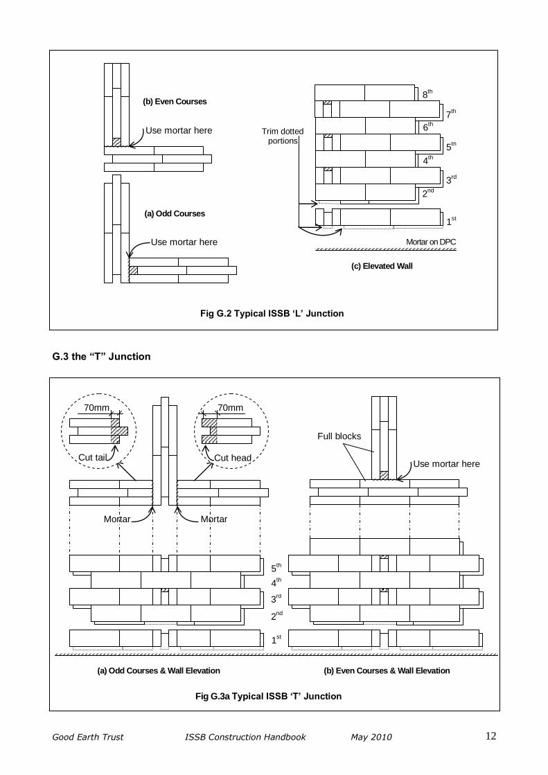
In ISSB construction where external walls are not rendered fully, the roof has an additional function
of protecting the exterior wall surfaces from scouring effects of driving rain. This can be achieved
by providing a sufficient roof over-hang ≥ 600 mm on plan. Where rainwater is to be harvested,
then most claddings are suitable except grass thatch. The adopted roof design must therefore be
able to fulfil these requirements using locally available materials.
H.2 Roof Structure and Connections
There are several designs and techniques of constructing roof structures ranging from single
spanning girders bearing on the walls and carrying the purlins, to roof trusses in larger buildings.
Often 100x75 mm timber wall plates serve as load transmission facility between the roof trusses or
rafters and the bearing walls; the wall plate also facilitates easy connection between the roof and
bearing walls of a house. Timbers must be joined to the required lengths using suitable connection
details.
The length of construction wood in Uganda is anywhere between 3000 mm to 4200 mm. If there is
need to join timber for roof elements, steel straps (hoop iron) can be used to splice together timber
members. These bands should be well secured with 50 mm wire nails.
Metallic roof anchors or straps must have been connected to the ring beam at convenient locations
where the roof trusses or rafters are to sit on the wall. The wall plate is then fastened to the wall
using the straps as shown in Fig H.2b below. Note that the channel in the last ISSB course is filled
with mortar to flush with the top of the blocks to provide a uniform base for the wall plates.
Fig H.1 ISSB Roof Requirements
Sufficient roof over-hang
600 mm
Window
Rendered wall section
Roof
Un-rendered ISSB wall
Incident rain
≥600 mm Ground level

Good Earth Trust ISSB Construction Handbook May 2010 18
H.3 Roof Cover and Rainwater Harvesting
The main rainwater harvesting elements of a roof are the roof cover and gutters. Most roof
covering materials in Uganda are suitable for rainwater harvesting with the exception of thatch and
asbestos. The gutter should be installed with a slight slope towards the collection point. Water can
either be drawn directly from the tank or by plumbing to serve the kitchen, toilet, and washroom.
Please refer to the section on Installing Technical Systems for guidelines on plumbing.
ISSB water tanks can be built both above and below ground: above ground ranging f rom 2,000L to
30,000L and below ground up to 100,000L. Compared to plastic tanks, ISSB tanks can generate
significant cost savings. Please refer to the Rainwater Harvesting Water Tank Manual for
guidelines.
Fig H.2b Roof Construction and Wall Connection Detail
ROOF TRUSS
Rafter
Tie Beam
Tying wire wound around wall plate & truss / rafter
Wall plate
ISSB wall
Tying wire flat on wall
Mortar here
Roofing nail
Roof cover (Iron sheet)
Rain gutter
Fascia board
Sheeting rail
Fig H.2a Wall Plate Connection
X
Wall plate (side elevation)
DETAIL AT X 100 mm
75 mm
3" Nails
100 mm

Good Earth Trust ISSB Construction Handbook May 2010 19
I. FINISHES
I.1 Introduction
When protecting the walls of an ISSB structure is required, the solution should be suited to the
local economy of the project context. One should therefore start by making sure it really is
necessary to protect the wall surfaces. An earth wall must never be rendered before the shrinkage
of the masonry during drying out has stabilized and the wall has been allowed to settle. This
means waiting for all structural work to be complete, including all the loads of floors and roofs.
I.2 Rendering / Plastering
The wall to which a render is to be applied must be free of all loose crumbly or dusty material. The
wall surface should therefore be carefully brushed, the wall must then me moistened by sprinkling
lightly with water in order to avoid capillary suction occurring – it should not be too wet as a film of
water at the surface would limit the adherence of the render. Note that the wall must not absorb the
water contained in the render or it will not set so well.
Application Conditions:
Do not render in very cold or very hot weather. Avoid driving rain, direct sun, violent winds
or very dry conditions. Slightly humid weather is ideal.
Apply the render in panels of 10-20 m2 at a time and complete each façade the same day.
Take care with the edges / corners and reveals.
On mixed support (e.g. earth and wood), incorporate wire mesh nailed on.
Do not render right down to ground level to avoid capillary suction.
Avoid the render drying out too quickly by sprinkling water onto the surface twice a day
(morning / evening) for the first seven consecutive days.
Renders are generally applied in two or three layers. The first layer, known as the rough coat or
‘primer’, is made up of a fairly fluid mortar which is thrown with force onto the wall using a trowel.
Between 3mm and 5mm thick, the surface of this layer is so rough so the next layer will stick more
easily. The second layer, known as the ‘coating’ or the ‘body’ is applied a-few days after the primer
(minimum 3 days) in one or two passes. This layer is 8mm to 20mm thick and is carefully
smoothed using a ruler and it should display no cracks. The third layer, known as ‘finishing’,
completes the rendering process and fills any shrinkage cracks which might have appeared in the
coating. The finishing render is usually 1mm to 3mm thick and normally applied onto the coating
immediately after it has been levelled-out and finished with a steel float. Where only two layers of
render are to be applied, the coating constitutes the final layer and must be adequately smoothed
with steel or wooden float when fresh and allowed to cure.
In proportioning the constituents of cement / lime render, one should limit the composition to
something in the order of 1 part of binder to 4 to 8 parts of sand. Note that stiff renders often fail to
adhere well to earth walls and the render must remain supple and moisture permeable to avoid the
risk of it peeling off or separating

Good Earth Trust ISSB Construction Handbook May 2010 20
The table below shows typical composition of lime-cement-sand renders by volume.
Render Vol. of Lime Vol. of Cement Vol. of Sand
1st Layer 2 1 4
2nd Layer 2 1 6
3rd Layer 2 1 8
I.3 Cement Shurry
Made up of 2 to 3 parts of sandy or clayey soil maxed with 1 part of cement, very diluted in water,
these are brushed on in at least 2 coats 24 hours apart. They should be used within 2 hours of
being mixed. Colouring can be added (mineral oxides) or water–repellents (2% calcium stearin)
I.4 Paints
These are generally fairly efficient but they must be able to breathe and be elastic (latex or acrylic).
Rigid paints must not be used on compressed earth masonry walls.

Good Earth Trust ISSB Construction Handbook May 2010 21
J. INSTALLING TECHNICAL SYSTEMS
J.1 Introduction
The design of the technical electrical or plumbing systems should be specifically suited to earth-
built constructions. Generally, there are three guiding principles:
The systems must be as centralized as possible.
Any incorporation of pipe-lines for supplying and removing fluids into the walls must be
avoided.
Cutting into the walls to make grooves for service conduits should be avoided.
It then follows from above that the technical installations must be designed in advance and not on
site or as an afterthought.
J.2 Electricity
Electrical systems are either visible or integrated into the masonry. Visible systems include cables,
casings, and electrical skirting boards; the main problem being how to attach them to the wall.
There are several solutions and maximum use can be made of materials incorporated in the
masonry system other than earth, such as wood or cement. For example, wires can be run along
skirting boards, then up alongside wooden frames, along the ring-beam or ceiling. Alternatively,
suitably sized wooden blocks can be carefully inserted into the masonry where cables are to be run
during block-laying. Then all that needs to be done is attach collars or pins to them. One can also
mould cement-sand blocks using the ISSB machine, integrate these blocks into the wall where
cables are to be run and then fix the cables to these using rawl-plugs.
Meanwhile, the cables can also be run through casings which are integrated into the thickness of
the wall during construction, and the junction boxes are integrated into the surface of the walls. The
casings can be run horizontally in special blocks made with deeper depressions or behind grooved
skirting boards. Gaps can also be left in the ring-beam and these then covered up using a joint-
cover on the façade. Maximum use must be made of wooden frames to run casings vertically.
The integration of plug sockets, light switches, and junction boxes can be done by carefully cutting
into the blocks and then fixing them with cement-rich mortar or using special blocks moulded in
sand-cement.
J.3 Plumbing
Water supply pipe-works should be integrated into the thickness of the floor to the maximum extent
possible. Where pipes pass through the walls, a protective pipe-sleeve should be used. Any other
pipes, horizontal or vertical, should remain visible and the same principle as for electrical cables
can be used for attaching them to the surface of the walls.

Good Earth Trust ISSB Construction Handbook May 2010 22
The principle for water removal is the same as for water supply but inspection hatches must be
included with very long pipes and where there are bends or junctions. Meanwhile, the walls close
to the bathroom and kitchen fittings (sink, hand-wash basin, shower, and bathtub) must without fail
be rendered or tiled. A floor drain should also be fitted to make it easier to clean the floor and to
evacuate water in the event of a leak. Good ventilation is also recommended to avoid
condensation.

Good Earth Trust ISSB Construction Handbook May 2010 23
K. SCAFFOLDING / PLATFORMS
When constructing walls at levels above the chest (normally between 1.0 – 1.5 m from a standing
position), it becomes increasingly strenuous to lay the blocks and difficult to level and plumb the
wall. Therefore, the block layers should always keep elevating their working positions by using
appropriate scaffolding systems or platforms. Simple, low-cost and safe scaffolds can be
constructed at the site using lower-grade timber and poles. For elevations up to 300 mm and
where the ground is stable and fairly level around the walls, two 300 x 25 mm timber boards sitting
directly on dry-stacked ISSB blocks at intervals not exceeding 1 m is a safe and inexpensive
accessibility means.
For elevations between 300 mm and 1 m, another inexpensive platform similar to the one above
uses ≥60 mm poles (eucalyptus or bush type) instead of the ISSB stacks. Two poles are buried in
the ground adjacent to each other about 400 mm apart and a cross-pole nailed onto them; bracing
poles may be required across the supports when the elevation is above 600 mm from the ground.
The platform should be clear of the wall.
Fig K.1 ISSB-stack Platform
≤1000 mm
Ground level
≤1000 mm ≤1000 mm
≥200 mm ≥200 mm
≤300 mm ISSB stacks 2 Pieces of 12"x1" timber
Stick this block firmly into the ground
Fig K.2 Pole-framed Platform
≤1000 mm
Ground level
≤1000 mm ≤1000 mm
≥200 mm ≥200 mm
≤1000 mm
≥60 mm poles
2 Pieces of 12"x1" timber Plant poles firmly
into the ground
END VIEW SIDE VIEW
Use 4" nails here
Bracing
≥400 mm
Wall
Platform clear of wall
Good Earth Trust ISSB Construction Handbook May 2010 24
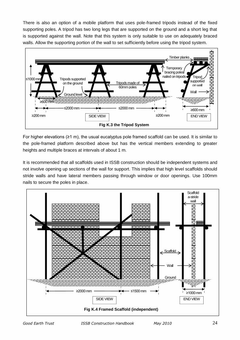
There is also an option of a mobile platform that uses pole-framed tripods instead of the fixed
supporting poles. A tripod has two long legs that are supported on the ground and a short leg that
is supported against the wall. Note that this system is only suitable to use on adequately braced
walls. Allow the supporting portion of the wall to set sufficiently before using the tripod system.
For higher elevations (≥1 m), the usual eucalyptus pole framed scaffold can be used. It is similar to
the pole-framed platform described above but has the vertical members extending to greater
heights and multiple braces at intervals of about 1 m.
It is recommended that all scaffolds used in ISSB construction should be independent systems and
not involve opening up sections of the wall for support. This implies that high level scaffolds should
stride walls and have lateral members passing through window or door openings. Use 100mm
nails to secure the poles in place.
Fig K.3 the Tripod System
≤2000 mm
Ground level
≤2000 mm
≥200 mm ≥200 mm
≤1000 mm
END VIEW SIDE VIEW
Tripods made of 60mm poles
≥600 mm
Wall
Tripod supported
on wall
≥600 mm
Temporary bracing poles
nailed on tripods Tripods supported
on the ground
Timber planks
Fig K.4 Framed Scaffold (independent)
≥2000 mm ≤1500 mm
END VIEW SIDE VIEW
≥1000 mm
Ground
Scaffold a-stride
wall
Wall
Scaffold

Good Earth Trust ISSB Construction Handbook May 2010 25
L. FURTHER READING
Operation Manual - “Ground Breaker” Block Press; Makiga Engineering Services Ltd., Nairobi
ISSB Machine Operation Manual; Technology for Tomorrow; Kampala 2008
Antje Ilberg, Chris Rollins; Low Cost House – Construction Manual; RISD (Rwanda Initiative for
Sustainable Development) Kigali City, 2007
Dr. E. A. Adam, Prof. A. R. A. Agib; Compressed Stabilised Earth Block Manufacture in Sudan;
United Nations Educational, Scientific and Cultural Organization (UNESCO), Paris 2001
Hubert Guilland, Thierry Joffroy, Pascal Odul; Compressed Earth Blocks Volume III – Manual of
Design and Construction; CRATerre-EAG (The International Centre for Earth Construction –
School of Architecture of Grenoble), 1995
Kenya Standard (KS 02-1070: 1993); Specification for stabilized Soil Blocks; Kenya Bureau of
Standards (KEBS), Nairobi 1993
TECHNOLOGY SERIES: Technical Memorandum No. 12; Small-Scale Manufacture of Stabilised
Soil Blocks; ILO – WEP (International Labour Office and the United Nations Industrial Development
Organisation), 1987

Good Earth Trust ISSB Construction Handbook May 2010 26
M. APPENDIX
M.1 Some Design Considerations for a low-cost house
While making design choices, keep in mind that “more”, “bigger” or “stronger” mean “more cost” but not
necessarily “better!”
The following are some of the architectural design aspects to be considered when developing ISSB building
plans:
1. How many rooms required? Therefore, how big should the house be? Note that room layouts should
maximize the functional use of the house with minimum redundant spaces.
2. Do you want to construct a separated kitchen? (And washroom / toilets?) Or would you like these in
the main house? The concept of having an open kitchen within the main house (as presented in both
home plans in this Section) is relatively cheaper than a closed-in (within the main house) or separated
kitchen.
3. Do you want to include in-built fuel efficient cooking devices in the kitchen? Options are for “rocket”
and equivalent stoves, bio-gas systems, etc.
4. Do you need a rainwater harvesting tank? If so, then suitable roof cover should be used to collect the
rainwater. We recommend a 5,000 litres tank for a typical home (Uganda).
5. What roof shape do you prefer: gable-ended or hipped roof? – consider the roof span; single Vs
double pitch
6. What door/window materials to use? The choice is usually between metal and timber, the latter being
relatively cheaper and more adaptive for use with ISSB construction.
7. Do you require roof ceiling? This is greatly influenced by cost and the type of roof cover – a tin (iron
sheet) roofed house without a ceiling can be hot in summer so make use of appropriate vents. Noise
due to rain impact can also be such an inconvenience.
8. What finishes (both internal including floor and external) to deploy?
9. Do you need to install building services (plumbing, sewerage, electricity, etc)?
The following are some of the structural aspects to be considered when developing adequate and durable
ISSB buildings:
1. Interlocking stabilized soil blocks are a recommended permanent building material, although they may
take proper training and experience to use properly.
2. Structurally sound blocks must be produced in accordance with the Block Making Manual and training
guidelines – where appropriate soils are chosen and recommended quality measures maintained
throughout the block production process.
3. No vertical joint should be positioned above another vertical joint.
4. Appropriate and strong ties or ring beams around the entire perimeter of the house at the top of the
major wall openings (windows and doors) which will prevent collapse at these locations.
5. A light-weight roof relative to the entire structure and adequately secured to the tie or ring beams.
6. Relatively small and uniform openings such as windows and doors that are no more than 30 percent the
wall length, and these openings should not be too close to or at corners if not necessary.
7. Good quality materials and workmanship, including plumb walls for guaranteed structural integrity.
8. Uniform thin mortar joints – 5 mm is sufficient and use a suitable gauging device.
9. Good external protection of the wall: sufficient roof overhang, and good drainage around the house.

Good Earth Trust ISSB Construction Handbook May 2010 27
M.2 Typical Low-Cost Home Plans
Fig M.2a 1-Bedroom ISSB Model Home

Good Earth Trust ISSB Construction Handbook May 2010 28
Fig M.2b 2-Bedroom ISSB Model Home

Good Earth Trust ISSB Construction Handbook May 2010 29
M.3 Sample Building of Costs
PROJECT : PROPOSED 57SQM LOW-COST ISSB MODEL HOME [2 beds + kitchen]
ISSB DEMAND : 6,360 BLOCKS [foundation - 1,320; super wall - 5,040]
CLIENT : FOUNDATION FOR RURAL HOUSING - UGANDA
SUBJECT : ITEMISED COSTING
DATE : MAR. '09
COMPILED BY : DAN A.; CHECKED BY : LISA B.
Item Description Unit Quantity Rate Amount Comments
A Preliminaries 281,500
1 Tools and equipment required Item 1 150,000 150,000 provisional sum
2 Site clearance m2 75 500 37,500 do
3 Setting-out facilitation Item 1 50,000 50,000 do
4 Trench excavations m3 11 4,000 44,000 do
B Cement 2,599,000
1 Cement for concrete (foundation strip) Bag 5 23,000 115,000 100mm thick, mix 1:3:6
2 Cement for concrete (ground slab) Bag 10 23,000 230,000 50mm thick, mix 1:3:6
3 Cement for mortar Bag 15 23,000 345,000 approx. 5mm, mix 1:3
4 Cement for internal plastering Bag 10 23,000 230,000 approx. 10mm, mix 1:4
5 Cement for rendering (external plastering) Bag 8 23,000 184,000 approx. 10mm, mix 1:5
6 Cement for screed & other finishes Bag 12 23,000 276,000 approx. 20mm, mix 1:4
7 Cement for block making (6,360 blocks) Bag 53 23,000 1,219,000 120 blocks per 50kg bag
C Stones and Aggregates 1,060,000
1 1/4" Agg. for concrete (foundation strip & floor top) Trip 2 120,000 240,000 50mm blinding on hardcore
2 3" (75mm) crushed stones for slab conc. base Trip 2 100,000 200,000 placed on compacted fill
3 Hardcore Trip 2 100,000 200,000 300mm wide around plinth
4 Coarse sand (concrete, mortar, plaster) Trip 2 120,000 240,000
5 Pit sand (concrete, mortar, plaster) Trip 2 90,000 180,000
D Reinforcements 365,000
1 Y12mm m/s (for tying wall) Bar 9 20,000 180,000 (no ring beam in the wall)
2 R5mm m/s for tying roof to wall Bar 0 6,000 0
3 1.2mm Flat bar (for tying roof to wall) No. 5 15,000 75,000 1 ring halfway in the wall
4 1.2mm Flat bar (in plinth wall) No. 0 15,001 0 2 ring halfway in the wall
5 Binding wire Kg 5 5,000 25,000
6 8'x4' Weld mesh (on top of plinth wall) No. 5 17,000 85,000
E Roofings 2,307,000
1 Wall plates (4"x3"x14' timber) No. 10 10,000 100,000 (hardwood timber)
2 Ridge Rafters (4"x3"x14' timber) No. 10 10,000 100,000 do
3 Under-purlin (4"x3"x14' timber) No. 6 10,000 60,000 do
4 Valley Rafters (4"x2"x14' timber) No. 2 6,000 12,000 do
5 Girders / Secondary Rafters (4"x2"x14' timber) No. 15 6,000 90,000 do
6 Purlins (3"x2"x14' timber) No. 36 4,500 162,000 do
7 Fascia boards (8"x1"x14' timber) No. 10 10,000 100,000 do
8 10 Ft long G30 iron sheets No. 54 21,000 1,134,000
9 6 Ft long G30 ridges No. 13 8,000 104,000
10 Valley Gutters No. 2 8,000 16,000
11 Wire nails (assorted) Kg 10 4,000 40,000
12 Roofing nails Kg 25 6,000 150,000
13 Rubber washers Pkt 3 8,000 24,000
14 Rain gutters (complete with accessories) m 15 10,000 150,000
15 Hoop iron for connecting timber Roll 1 65,000 65,000
F Scaffolding 60,000
1 12"x1" timber ("kirundu" ) for platforms
2 2"-3" Eucalyptus poles Item 1 60,000 60,000
3 Assorted wire nails
G Doors & Windows 1,335,000
1 Standard solid timber door No. 4 150,000 600,000
2 Standard solid timber window No. 5 120,000 600,000
3 Vents No. 3 45,000 135,000
H Miscellaneous Items 550,000
1 DPC (bituminous felt) Roll 2 10,000 20,000
2 Lime for plastering Bag 5 20,000 100,000
3 Hollow steel pipes (60x2mm) No. 2 40,000 80,000
4 Painting m2 140 2,500 350,000
I TOTAL 8,557,500
1 Labour (20% of Total less preliminaries) Item 0.2 8,276,000 1,655,200 2 General Contigency (5% of Total less prelim.) Item 0.05 8,276,000 413,800
J GRAND TOTAL 10,626,500
5,000Lts ISSB Water Tank Item 1 750,000 750,000 750,000
1-Stance VIP Latrine Item 1 1,770,000 1,770,000 1,770,000
OVERALL COST 13,146,500


![ISSB Water Tank Consruction Manual 120908 FINAL[1]](https://img.dokumen.tips/doc/110x75/543d24b8afaf9fa00a8b4569/issb-water-tank-consruction-manual-120908-final1.jpg)