Embed Size (px)
Citation preview

CARBON OAK, INC. THUNDER OAKS MINE, P-3976
DIVERSION DITCH No. 1
DRAINAGE CONTROL BERM DIVERSION DITCH No. 2
CULVERT C-1 DIVERSION DITCH No. 3
DETAILED DESIGN PLANS
Submitted by: TASK Engineering Management Inc.
P. O. Box 660548 Birmingham, Alabama 35266
Telephone: (205) 978-5070 Email: [email protected]

TASK ENGINEERING MANAGEMENT INC. PO Box 660548
BUUOMGHAM,ALABAMA35266 (205) 978-5070
March 23, 2014
Mr. Gary J. Heaton, P.E. Alabama Surface Mining Commission PO Box 2390 Jasper, Alabama 35502-2390
Re: Carbon Oak, Inc. Thunder Oaks Mine - P-3976
Dear Mr. Heaton:
I hereby certifY the enclosed detailed design plans for Diversion No. 1, Diversion No. 2 and Drainage Control Berm, Culvert C-I and Diversion No. 3 for the above referenced mine are in accordance with the Regulations of the Alabama Surface Mining Commission as adopted by Act 81-435 of December 18, 1981 and as amended to date and that the information used in the enclosed diversion berm design plans is true and correct to the best of my knowledge and belief.
If you have any questions or need additional information, please do not hesitate to call us at (205) 978-5070 or email [email protected].
Sincerely,
",,,n,,,,,, , ..." I'\. B A III"
"", r Il? '" Chjkv~~ \0. & • • •••••• , ... " 'V._ T -.$ A!7 .,~~ _-,-.\5 ~.o.e. T ~ ~ .... erv'V' ·T(':·. .. .. :./'J..:. <:) -. :. Jerry W. Williams, P.E. .... ' -l;l 411:: *: No. 12739 : :. Alabama Reg. No. 12739 = :• PROF£SSION ,\L : v;_ • , ,.. .:~ :.~.. : ~.; ... A\. "" "'- • 00::: ... ... \.: • ,.", "- '<' • ~ •
~ , -PI'j)••••-.GINS"".••••, " ...;l -., I.. • ••••• ~ \..V .. '"'' r W \t.I\ ........
"1 • '4'1 , .. " 11"1111'''''\

Carbon Oak, Inc. Thunder Oaks Mine, P-3976
INTRODUCTION
For Thunder Oaks Mine, P-3976, drainage control during the mining of Increments No. 1 and No. 2 will be accomplished by the construction of a drainage control berm, three (3) drainage diversion ditches and two (2) sedimentation basins. Drainage to the north of Dekalb County Road 683 will be conveyed to Sediment Basin 001 via natural existing drainage channels and drainage to the south of Dekalb 683 will be convey via the following proposed drainage control berm and drainage ditch.
Presently within the reclaimed area of previous mining operations in the NE/SW of Section 3, there are two (2) existing ponds left from these operations labeled Pond #1 and Pond #2 as shown on the map entitled Drainage Diversions - Plan/Profile. Both ponds are incised and are approximately forty (40') feet deep and were left at the request of the landowner during reclamation operations. Diversion No. 1 will be constructed to convey drainage from the northwest area of the NE/SW of Section 3 where a topsoil storage area is proposed into the existing drainage channel and hence into Pond #2. Diversion No. 1 will extend from Station 0+00 to Station 3+15.15 where it will intersect with the existing drainage channel.
Presently drainage flows to the northeast from Pond #1 to Pond #2 and then discharges from Pond #2 to the south into the existing drainage channel of an unnamed tributary of Bengis Creek. At the point of entry to the drainage channel there exists a wetland area present on both sides of the tributary extending due east then south/southeasterly to where the tributary is conveyed under Dekalb County Road 681 via two (2) forty-two (42") inch bituminous coated corrugated drainage culverts. As part of the Compensatory Mitigation Plan with the Army Corp of Engineers (ACOE), these wetland areas will be avoided and left intact per the mining plan of operations at the site. This will be accomplished by the construction of a diversion berm and the construction of a riprap lined diversion ditch that will convey and isolate the drainage from the proposed mining operations to Sediment Basin 009 due south of Dekalb County 681 in the SW/SE of Section 3. To minimize the impact to the existing drainage channel of the unnamed tributary a new drainage culvert will be installed under Dekalb 681 to convey flow from the proposed mining operations to Sediment Basin 009.
The diversion berm and diversion ditch are labeled Diversion No. 2 on the map entitled Drainage Diversions - Plan/Profile and along with Basins 001 and 009 will be designed, approved, constructed and certified to the Regulatory Authority prior to any active mining within Increments No. 1 and No. 2 of the Thunder Oaks Permit.
The Drainage Control Berm will be constructed by first re-establishing the outflow from Pond #1 to the natural stream channel of the unnamed tributary due east of the embankment of Pond #1 and tying the berm to existing ground between Pond #1 and Pond #2. The berm commences at natural ground level in the NE/SW of Section 3 at Station 0+04.56 and will be constructed on top of the existing embankment of Pond #2, will cut-off the flow of the existing outlet channel to the
Carbon Oak, Inc. Thunder Oaks Mine, P-3976
south from the pond and will channel the pond discharge into the constructed rip-rap lined diversion ditch at Station 3+64.79. From this point the diversion will flow along the proposed permit boundary in the NW/SE into SW/SE of Section 3, will tie into the existing road embankment of Dekalb Road 681at Station 17+28.65, under the roadway via the proposed drainage culvert and into Basin 009. (See the attached Drainage Diversions Plan/Profile for the location/orientation of the drainage berm structure.)
This configuration will remain until completion of mining in Increments No. 1 and No. 2. Upon activation of Increment No. 3 and prior to any mining operations, Basin 008 will be will be designed, approved, constructed and certified to the Regulatory Authority prior to any active mining within Increment No. 3 of the Thunder Oaks Permit and Basin 009 will be pumped dry and a new drainage channel will be constructed by placing spoil material within the storage area of Basin 009 and lining the channel with 1.0 foot of clay and certified as reconstructed to the Regulatory Authority. Diversion No. 2 and the corresponding drainage culvert will remain as permanent fixtures to isolate the existing wetland area.
CONSTRUCTION AND CERTIFICATION REQUIREMENTS
Due to low inherent surface slopes at the Thunder Oaks mine site, the Drainage Control Berm and Sedimentation Basins 001P and 009P will be constructed prior to any surface coal mining operations are commenced. These facilities will allow for the protection of the existing wetland areas from the proposed surface coal mining operations and will insure that all drainage resulting from natural flows and storm water will be routed through approved sedimentation basins for treatment prior to discharge into Bengis Creek.
The Drainage Control Berm will be built, stabilized and certified in five hundred (500') foot sections and the previously referenced Sedimentation Basins 001P and 009P will be built and certified to the Regulatory Authority prior to any mining disturbance within their corresponding watersheds.
The Drainage Control Berm will be constructed of the best non-toxic, non-acid material resulting from the excavation of the proposed incised sedimentation Basin 009 and compacted to 95%, based on standard proctor as outlined by ASTM. The construction materials will be free of sod, stones, roots, limbs, etc. over six (6") inches in diameter and spread in layers no greater that twelve (12") inches in thickness.
The foundation area of the berm structure will be cleared and grubbed of all organic matter such as tree and large bushes prior to construction and will be constructed at a maximum height of seven (7') feet above existing ground, will be ten (10') in width at the top and the sides will be

Carbon Oak, Inc. Thunder Oaks Mine, P-3976
sloped at two (2') feet horizontal to one (1') foot vertical. (See the attached Typical Drainage Control Berm Section for a typical details of the drainage berm structure and see the attached Drainage Diversions - Plan/Profile, Cross-Sections 0+04.56 to 12+50 and Cross-Sections 13+00 to 17+00 for the general plan view, top of berm and ground profiles and cross-sections showing ground elevation and top of berm elevations at the centerline of the proposed Drainage Control Berm.)
All areas disturbed in the construction of the berm structure will be seeded with a mixture of perennial and annual grasses, fertilized and mulched to prevent erosion and ensure restabilization. Silt fence will be installed where toe of the slope of the berm structure intersects natural ground. (See the attached Silt Fence Detail and Silt Fence Specifications).
The Drainage Control Berm will be constructed, stabilized and certified in intervals of five hundred (500') feet. Inspections will be conducted regularly during construction of the berm structure by a qualified registered engineer or other qualified person under the direction of a professional engineer. Upon completion of construction, the interval will be certified, by a qualified Registered Professional Engineer, to the Regulatory Authority as being constructed in accordance with the approved Detailed Design Plans.

Carbon Oak, Inc. Thunder Oaks Mine, P-3976
DIVERSION DITCH AND DIVERSION BERM DESIGN AND CONSTRUCTION SPECIFICATIONS
1) Temporary diversions will be designed and constructed to adequately carry the runoff from a two (2) year - six (6) hour precipitation event. 2) Permanent diversions will be designed and constructed to adequately carry the runoff from a ten (10) year - six (6) hour precipitation event.
3) Permanent diversions will be designed and constructed with gently sloping banks stabilized with appropriate vegetation.
4) All diversions will be designed, constructed and maintained, using the best technology currently available, whereas additional contribution of suspended solids to stream-flow and to runoff outside the permit area is prevented.
5) Maintenance of appropriate gradient, channel lining, revegetation, roughness structures, detention basins, etc. will be used, when necessary, as sediment control measures for these diversions.
6) Diversions will not be constructed on existing landslides nor be located so as to increase the potential for landslides.
7) Temporary diversions will be removed and the affected area regraded, topsoiled (if required) and revegetated in accordance with Rules 880-X-10C-.10, 880-X-10C-.11, 880- X-10C-.52 thru 880-X-10C-.57 and 880-X-10C-.58, 880-X-10C-.60 and 880-X-10C-.62, when no longer needed.
8) Channel linings, for diversions with slopes of three (3%) percent or less, will consist of a mixture of both annual and perennial grasses being predominantly fescue and bermuda. Channel linings, for diversions with slopes greater than three (3%) percent, will consist of rip-rap or other non-erodible material or cut into non-erodible material.
9) Adequate freeboard will be provided for protection for transition of flows and critical areas such as swales and curves along the entire diversion length.
10) At discharge points where diversions intersect with natural streams or exit velocities of the diversion are greater than that of the receiving streams, energy dissipaters will be installed when deemed necessary.
11) Topsoil removed from the diversion area (if required) will be handled in accordance with Rules 880-X-10C-.07 thru 880-X-10C-.11.
12) Excess material excavated in the construction of the diversion, not needed for diversion channel geometry or the regrading of the channel, will be disposed of in accordance with Rule 880-X-10C-.36.
13) Diversions will not be designed or constructed to divert water into underground mines without written approval from the Regulatory Authority.

Carbon Oak, Inc. Thunder Oaks Mine, P-3976
14) The entire area in which a diversion berm is proposed will be cleared and grubbed of all organic material, scarified and no surface slopes will be left steeper than one (1) Vertical to one (1) Horizontal.
15) Diversion berms will be constructed with desirable material, free of sod, stones, roots, limbs, etc. over six (6) inches in diameter. This material will be spread in layers no greater than twelve (12) inches in thickness and compacted to ninety-five (95%) percent of the standard proctor density, as outlined in ASTM, until the design height is reached.
16) Upon completion of diversion ditches or diversion berms, all disturbed areas will be seeded with a mixture of both annual and perennial grasses, fertilized and mulched in order to minimize erosion and ensure restabilization.
17) All diversions (berms or ditches) will be examined quarterly for erosion, instability, structural weakness or other hazardous conditions and maintenance performed as necessary.
18) The diversion will be constructed and stabilized in 500 feet sections.

Carbon Oak, Inc. Thunder Oaks Mine, P-3976
REMOVAL PLAN FOR DRAINAGE CONTROL BERM
Berms associated with Diversion Ditches No. 1, and No. 3 will be removed after a Phase II bond release for the area draining to the diversions.
Prior to removal, silt fences will be installed along the outside edge of the berm to control runoff from the area disturbed. See Silt Fence Design and Construction Specifications and drawings for silt fence placement.
The berm will be removed by grading the material into the adjacent permit area that has been surface mined. The area will be sloped to comply with Part IV of the permit. As soon as grading is complete, the area will be scarified, seeded and mulched in accordance with the approved Part IV of the permit.
Diversion No. 2 is to be permanent to isolate the existing wetland areas to the south of the berm structure and will not be removed.

Carbon Oak, Inc. Thunder Oaks Mine, P-3976
DETAILED DESIGN PLANS DIVERSION DITCH No.1
Submitted by:
TASK Engineering Management Inc. P. O. Box 660548
Birmingham, Alabama 35266 Telephone: (205) 978-5070 Email: [email protected]


Carbon Oak, Inc.Thunder Oaks Mine
Diversion No. 1
SCS - 6 HR2 Year-6 Hour Event, 2.63 In.
Jerry W. Williams, P.E.
TASK Engineering Management Inc.P.O. Box 660548
Birmingham, Alabama 35226
Phone: 205-978-5070Email: [email protected]
Filename: DIVERSION No. 1.sc4 Printed 03-23-2014
SEDCAD 4 for WindowsCopyright 1998 -2010 Pamela J. SchwabCivil Software Design, LLC 1

General Information
Storm Information:Storm Type: SCS-6 HOUR
Design Storm: 2 yr - 6 hr
Rainfall Depth: 2.630 inches
Filename: DIVERSION No. 1.sc4 Printed 03-23-2014
SEDCAD 4 for WindowsCopyright 1998 -2010 Pamela J. SchwabCivil Software Design, LLC 2

Structure Networking:Type Stru # (flows
into) Stru # Musk. K(hrs) Musk. X Description
Channel #1 ==> End 0.000 0.000 DIVERSION No. 1 - GRASS LINEDCHANNEL
#1
Chan'l
Filename: DIVERSION No. 1.sc4 Printed 03-23-2014
SEDCAD 4 for WindowsCopyright 1998 -2010 Pamela J. SchwabCivil Software Design, LLC 3

Structure Summary:Immediate
ContributingArea
(ac)
TotalContributing
Area
(ac)
PeakDischarge
(cfs)
TotalRunoffVolume
(ac-ft)
#1 2.410 2.410 2.54 0.21
Filename: DIVERSION No. 1.sc4 Printed 03-23-2014
SEDCAD 4 for WindowsCopyright 1998 -2010 Pamela J. SchwabCivil Software Design, LLC 4

Structure Detail:Structure #1 (Vegetated Channel)
DIVERSION No. 1 - GRASS LINED CHANNEL
Triangular Vegetated Channel Inputs:
Material: Tall fescue
LeftSideslope
Ratio
RightSideslope
RatioSlope (%) Retardance
ClassesFreeboard
Depth (ft)
Freeboard
% of Depth
Freeboard
Mult. x (VxD)
LimitingVelocity (fps)
2.0:1 2.0:1 1.5 D, B 1.00 7.0
Vegetated Channel Results:
Stability
Class D w/oFreeboard
Stability
Class D w/Freeboard
Capacity
Class B w/oFreeboard
Capacity
Class B w/Freeboard
Design Discharge: 2.54 cfs 2.54 cfs
Depth: 0.92 ft 1.92 ft 1.51 ft 2.51 ft
Top Width: 3.68 ft 7.68 ft 6.04 ft 10.04 ft
Velocity: 1.50 fps 0.56 fps
X-Section Area: 1.70 sq ft 4.56 sq ft
Hydraulic Radius: 0.412 ft 0.675 ft
Froude Number: 0.39 0.11
Roughness Coefficient: 0.0676 0.2529
Filename: DIVERSION No. 1.sc4 Printed 03-23-2014
SEDCAD 4 for WindowsCopyright 1998 -2010 Pamela J. SchwabCivil Software Design, LLC 5

Subwatershed Hydrology Detail:
Stru # SWS#
SWS Area
(ac)
Time of Conc
(hrs)
Musk K
(hrs)Musk X
Curve
NumberUHS
PeakDischarge
(cfs)
RunoffVolume
(ac-ft)
#1 1 2.410 0.098 0.000 0.000 81.000 F 2.54 0.208
2.410 2.54 0.208
Subwatershed Time of Concentration Details:Stru # SWS
# Land Flow Condition Slope (%) Vert. Dist.(ft)
Horiz. Dist.(ft) Velocity (fps) Time (hrs)
#1 1 5. Nearly bare and untilled, and alluvialvalley fans 2.17 8.64 397.38 1.470 0.075
8. Large gullies, diversions, and lowflowing streams 1.51 4.77 315.16 3.690 0.023
#1 1 Time of Concentration: 0.098
Filename: DIVERSION No. 1.sc4 Printed 03-23-2014
SEDCAD 4 for WindowsCopyright 1998 -2010 Pamela J. SchwabCivil Software Design, LLC 6

Carbon Oak, Inc. Thunder Oaks Mine, P-3976
DETAILED DESIGN PLANS DIVERSION DITCH No.2
DRAINAGE CONTROL BERM
Submitted by:
TASK Engineering Management Inc. P. O. Box 660548
Birmingham, Alabama 35266 Telephone: (205) 978-5070 Email: [email protected]


Carbon Oak, Inc.Thunder Oaks Mine
Diversion No. 2
SCS - 6 HR10 Year-6 Hour Event, 3.67 In.
Jerry W. Williams, P.E.
TASK Engineering Management Inc.P.O. Box 660548
Birmingham, Alabama 35226
Phone: 205-978-5070Email: [email protected]
Filename: DIVERSION No. 2.sc4 Printed 03-23-2014
SEDCAD 4 for WindowsCopyright 1998 -2010 Pamela J. SchwabCivil Software Design, LLC 1

General Information
Storm Information:Storm Type: SCS-6 HOUR
Design Storm: 10 yr - 6 hr
Rainfall Depth: 3.670 inches
Filename: DIVERSION No. 2.sc4 Printed 03-23-2014
SEDCAD 4 for WindowsCopyright 1998 -2010 Pamela J. SchwabCivil Software Design, LLC 2
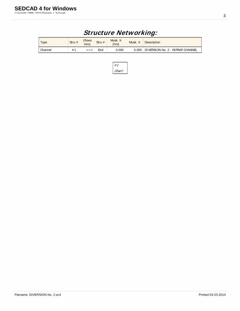
Structure Networking:Type Stru # (flows
into) Stru # Musk. K(hrs) Musk. X Description
Channel #1 ==> End 0.000 0.000 DIVERSION No. 2 - RIPRAP CHANNEL
#1
Chan'l
Filename: DIVERSION No. 2.sc4 Printed 03-23-2014
SEDCAD 4 for WindowsCopyright 1998 -2010 Pamela J. SchwabCivil Software Design, LLC 3

Structure Summary:Immediate
ContributingArea
(ac)
TotalContributing
Area
(ac)
PeakDischarge
(cfs)
TotalRunoffVolume
(ac-ft)
#1 85.000 85.000 105.20 11.19
Filename: DIVERSION No. 2.sc4 Printed 03-23-2014
SEDCAD 4 for WindowsCopyright 1998 -2010 Pamela J. SchwabCivil Software Design, LLC 4

Structure Detail:Structure #1 (Riprap Channel)
DIVERSION No. 2 - RIPRAP CHANNEL
Trapezoidal Riprap Channel Inputs:
Material: Riprap
BottomWidth (ft)
LeftSideslope
Ratio
RightSideslope
RatioSlope (%)
Freeboard
Depth (ft)
Freeboard
% of Depth
Freeboard
Mult. x (VxD)
10.00 2.0:1 2.0:1 0.9 1.00
Riprap Channel Results:
PADER Method - Mild Slope Design
w/o Freeboard w/ Freeboard
Design Discharge: 105.20 cfs
Depth: 1.68 ft 2.68 ft
Top Width: 16.70 ft 20.70 ft
Velocity: 4.70 fps
X-Section Area: 22.36 sq ft
Hydraulic Radius: 1.279 ft
Froude Number: 0.72
Manning's n: 0.0350
Dmin: 2.00 in
D50: 3.00 in
Dmax: 4.50 in
Filename: DIVERSION No. 2.sc4 Printed 03-23-2014
SEDCAD 4 for WindowsCopyright 1998 -2010 Pamela J. SchwabCivil Software Design, LLC 5

Subwatershed Hydrology Detail:
Stru # SWS#
SWS Area
(ac)
Time of Conc
(hrs)
Musk K
(hrs)Musk X
Curve
NumberUHS
PeakDischarge
(cfs)
RunoffVolume
(ac-ft)
#1 1 32.650 0.066 0.150 0.365 74.000 M 44.31 3.696
2 2.680 0.010 0.148 0.307 100.000 F 9.42 0.819
3 15.220 0.145 0.028 0.330 79.000 M 15.82 1.751
4 30.210 0.244 0.000 0.000 81.000 F 41.24 4.423
5 4.240 0.103 0.000 0.000 75.000 S 6.11 0.503
85.000 105.20 11.192
Subwatershed Time of Concentration Details:Stru # SWS
# Land Flow Condition Slope (%) Vert. Dist.(ft)
Horiz. Dist.(ft) Velocity (fps) Time (hrs)
#1 1 3. Short grass pasture 3.42 12.09 353.58 1.470 0.066
#1 1 Time of Concentration: 0.066
#1 3 3. Short grass pasture 2.99 8.92 298.46 1.380 0.060
8. Large gullies, diversions, and lowflowing streams 2.39 34.30 1,433.14 4.640 0.085
#1 3 Time of Concentration: 0.145
#1 4 5. Nearly bare and untilled, and alluvialvalley fans 0.89 4.14 467.61 0.940 0.138
8. Large gullies, diversions, and lowflowing streams 3.07 61.90 2,018.01 5.250 0.106
#1 4 Time of Concentration: 0.244
#1 5 3. Short grass pasture 4.24 17.01 400.76 1.640 0.067
8. Large gullies, diversions, and lowflowing streams 3.58 26.40 736.50 5.670 0.036
#1 5 Time of Concentration: 0.103
Subwatershed Muskingum Routing Details:Stru # SWS
# Land Flow Condition Slope (%) Vert. Dist.(ft)
Horiz. Dist.(ft) Velocity (fps) Time (hrs)
#1 2 8. Large gullies, diversions, and lowflowing streams 0.82 11.84 1,444.47 2.710 0.148
#1 2 Muskingum K: 0.148
#1 3 8. Large gullies, diversions, and lowflowing streams 1.21 4.13 342.27 3.290 0.028
#1 3 Muskingum K: 0.028
Filename: DIVERSION No. 2.sc4 Printed 03-23-2014
SEDCAD 4 for WindowsCopyright 1998 -2010 Pamela J. SchwabCivil Software Design, LLC 6

Carbon Oak, Inc. Thunder Oaks Mine, P-3976
DETAILED DESIGN PLANS CULVERT C-1
Submitted by:
TASK Engineering Management Inc. P. O. Box 660548
Birmingham, Alabama 35266 Telephone: (205) 978-5070 Email: [email protected]
Carbon Oak, Inc. Thunder Oaks Mine, P-3976
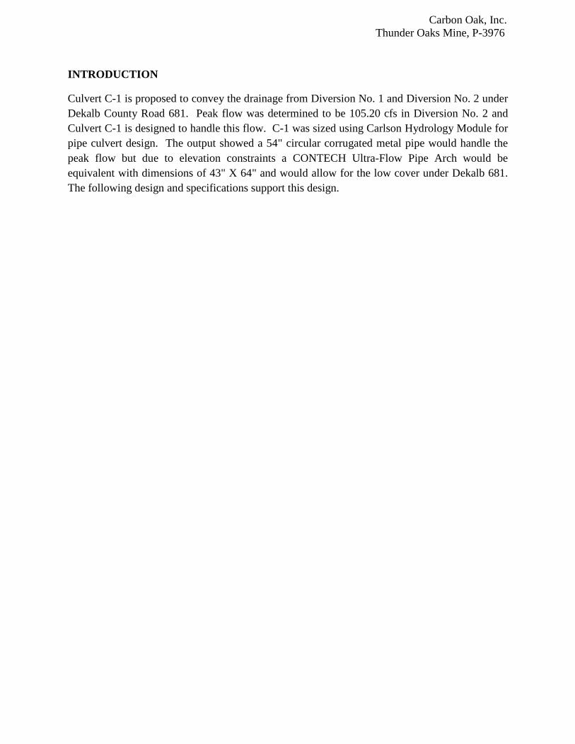
INTRODUCTION
Culvert C-1 is proposed to convey the drainage from Diversion No. 1 and Diversion No. 2 under Dekalb County Road 681. Peak flow was determined to be 105.20 cfs in Diversion No. 2 and Culvert C-1 is designed to handle this flow. C-1 was sized using Carlson Hydrology Module for pipe culvert design. The output showed a 54" circular corrugated metal pipe would handle the peak flow but due to elevation constraints a CONTECH Ultra-Flow Pipe Arch would be equivalent with dimensions of 43" X 64" and would allow for the low cover under Dekalb 681. The following design and specifications support this design.

C-1 Culvert Design (Carlson Hydrology Routine) Sat Mar 22 12:15:23 2014
File: C:\Users\JERRY61\Desktop\ARCH PIPE DESIGN\TO PIPE3.clt
Design Parameters Section Shape: Circular Material: CONTECH Ultra-Flow Diameter: 54.00 in Equivalent (43" X 64" PIPE ARCH)* Manning's n: 0.0120 Number of Barrels: 1 Inlet Inlet Type: Mitered to Slope Ke: 0.70 Inverts Inlet Invert Elevation: 1255.660 ft Outlet Invert Elevation: 1254.510 ft Length: 115.000 ft Slope: 1.00 %
Culvert Calculation Discharge: 106.34 cfs Headwater Elevation: 1259.720 ft Tailwater Elevation: 1256.510 ft Downstream Velocity: 13.41 ft/s Downstream Flow Depth: 2.245 ft Flow Control Type: Inlet Control, Unsubmerged *SEE FOLLOWING DETAILS


11
Diameter Minimum or Span Cover (In.) (In.) 18 16 14 12 10 8(5)
6 (4) 12 197 247
8 (4) 147 185
10 (4) 119 148
12 125 157
15 100 125
18 83 104
21 71 89
24 62 78 109
27 69 97
30 62 87
36 51 73 94
42 62 80
48 12 54 70 85
54 15 48 62 76
60 15 52 64
66 18 52
72 18 43
Equiv. Standard Gage
2-2/3” X 1/2” Height-of-Cover Limits for Corrugated Aluminum Pipe
HL 93 Live LoadMaximum Cover, (Ft.)(2)
Corrugated Aluminum PipeHeights-of-Cover
Heights-of-Cover
3” x 1” Height-of-Cover Limits for Corrugated Aluminum Pipe
HL 93 Live Load
Diameter Minimum(3) or Span Cover (In.) (In.) 16 14 12 10 8(6) 30 12 57 72 101 135 159
36 47 60 84 112 132
42 40 51 72 96 113
48 12 35 44 62 84 99
54 15 31 39 55 74 88
60 15 28 35 50 67 79
66 18 25 32 45 61 72
72 18 23 29 41 56 66
78 21 27 38 51 61
84 21 35 48 56
90 24 33 44 52
96 24 31 41 49
102 24 39 46
108 24 37 43
114 24 39
120 24 36
Equiv. Standard GageMaximum Cover, (Ft.) (2)
3” x 1” Height-of-Cover Limits for Corrugated Aluminum Pipe-Arch
2 2/3" x 1/2" Height-of-Cover Limits for Corrugated Aluminum Pipe-Arch
Notes:1. Height-of-cover is measured to top of rigid pavement or to bottom of flexible pavement.2. Maximum cover meets AASHTO LRFD design criteria.3. Minimum cover meets AASHTO and ASTM B 790 design criteria.4. 1 1/2” x 1/4” corrugation.5. 8-gage pipe has limited availability.6. For construction loads, see page 15.
Notes:1. Height-of-cover is measured to top of rigid pavement or to bottom of flexible pavement.2. Maximum cover meets AASHTO LRFD design criteria.3. Minimum cover meets ASTM B 790 design criteria.4. Limited availability on these sizes.5. 8-gage pipe has limited availability.6. For construction loads, see page 15.
HL 93 Live Load
Round PipeDia. (Inches)
Size, (In.)Span x
RiseMinimum
Gage
Minimum(3)
Cover(Inches)
Maximum Cover, (Ft.)Aluminum Pipe-Arch(2)
2 Tons/Ft.2 for Corner Bearing
Pressures
15 17x13 16 12 1318 21x15 16 12 1221 24x18 16 12 1224 28x20 14 12 1230 35x24 14 12 1236 42x29 12 12 1242 49x33 12 15 1248 57x38 10 15 1254 64x43 10 18 1260 71x47 8(5) 18 12
HL 93 Live Load
Round PipeDia. (Inches)
Size, (In.)Span x
RiseMinimum
Gage
Minimum(3)
Cover(Inches)
Maximum Cover, (Ft.)Aluminum Pipe-Arch(2)
2 Tons/Ft.2 for Corner Bearing
Pressures
54 60x46 14 15 20
60 66x51 14 18 20
66 73x55 14 21 20
72 81x59 12 21 16
78(4) 87x63 12 24 16
84(4) 95x67 12 24 16
90(4) 103x71 10 24 16
96(4) 112x75 8(5) 24 16
Carbon Oak, Inc. Thunder Oaks Mine, P-3976
DETAILED DESIGN PLANS DIVERSION DITCH No.3
Submitted by:
TASK Engineering Management Inc. P. O. Box 660548
Birmingham, Alabama 35266 Telephone: (205) 978-5070 Email: [email protected]


Carbon Oak, Inc.Thunder Oaks Mine
Diversion No. 3
SCS - 6 HR10 Year-6 Hour Event, 3.67 In.
Jerry W. Williams, P.E.
TASK Engineering Management Inc.P.O. Box 660548
Birmingham, Alabama 35226
Phone: 205-978-5070Email: [email protected]
Filename: DIVERSION No. 3.sc4 Printed 03-23-2014
SEDCAD 4 for WindowsCopyright 1998 -2010 Pamela J. SchwabCivil Software Design, LLC 1

General Information
Storm Information:Storm Type: SCS-6 HOUR
Design Storm: 10 yr - 6 hr
Rainfall Depth: 3.670 inches
Filename: DIVERSION No. 3.sc4 Printed 03-23-2014
SEDCAD 4 for WindowsCopyright 1998 -2010 Pamela J. SchwabCivil Software Design, LLC 2

Structure Networking:Type Stru # (flows
into) Stru # Musk. K(hrs) Musk. X Description
Channel #1 ==> End 0.000 0.000 DIVERSION No. 3 - RIPRAP CHANNEL
#1
Chan'l
Filename: DIVERSION No. 3.sc4 Printed 03-23-2014
SEDCAD 4 for WindowsCopyright 1998 -2010 Pamela J. SchwabCivil Software Design, LLC 3

Structure Summary:Immediate
ContributingArea
(ac)
TotalContributing
Area
(ac)
PeakDischarge
(cfs)
TotalRunoffVolume
(ac-ft)
#1 90.310 90.310 107.57 11.82
Filename: DIVERSION No. 3.sc4 Printed 03-23-2014
SEDCAD 4 for WindowsCopyright 1998 -2010 Pamela J. SchwabCivil Software Design, LLC 4

Structure Detail:Structure #1 (Riprap Channel)
DIVERSION No. 3 - RIPRAP CHANNEL
Trapezoidal Riprap Channel Inputs:
Material: Riprap
BottomWidth (ft)
LeftSideslope
Ratio
RightSideslope
RatioSlope (%)
Freeboard
Depth (ft)
Freeboard
% of Depth
Freeboard
Mult. x (VxD)
10.00 2.0:1 2.0:1 1.0 1.00
Riprap Channel Results:
PADER Method - Mild Slope Design
w/o Freeboard w/ Freeboard
Design Discharge: 107.57 cfs
Depth: 1.64 ft 2.64 ft
Top Width: 16.55 ft 20.55 ft
Velocity: 4.95 fps
X-Section Area: 21.73 sq ft
Hydraulic Radius: 1.254 ft
Froude Number: 0.76
Manning's n: 0.0350
Dmin: 2.00 in
D50: 3.00 in
Dmax: 4.50 in
Filename: DIVERSION No. 3.sc4 Printed 03-23-2014
SEDCAD 4 for WindowsCopyright 1998 -2010 Pamela J. SchwabCivil Software Design, LLC 5

Subwatershed Hydrology Detail:
Stru # SWS#
SWS Area
(ac)
Time of Conc
(hrs)
Musk K
(hrs)Musk X
Curve
NumberUHS
PeakDischarge
(cfs)
RunoffVolume
(ac-ft)
#1 1 32.650 0.066 0.150 0.365 74.000 M 44.31 3.696
2 2.680 0.010 0.148 0.307 100.000 F 9.42 0.819
3 15.220 0.145 0.028 0.330 79.000 M 15.82 1.751
4 30.210 0.244 0.000 0.000 81.000 F 41.24 4.423
5 4.240 0.103 0.000 0.000 75.000 S 6.11 0.503
6 5.310 0.107 0.000 0.000 75.000 S 7.66 0.629
90.310 107.57 11.821
Subwatershed Time of Concentration Details:Stru # SWS
# Land Flow Condition Slope (%) Vert. Dist.(ft)
Horiz. Dist.(ft) Velocity (fps) Time (hrs)
#1 1 3. Short grass pasture 3.42 12.09 353.58 1.470 0.066
#1 1 Time of Concentration: 0.066
#1 3 3. Short grass pasture 2.99 8.92 298.46 1.380 0.060
8. Large gullies, diversions, and lowflowing streams 2.39 34.30 1,433.14 4.640 0.085
#1 3 Time of Concentration: 0.145
#1 4 5. Nearly bare and untilled, and alluvialvalley fans 0.89 4.14 467.61 0.940 0.138
8. Large gullies, diversions, and lowflowing streams 3.07 61.90 2,018.01 5.250 0.106
#1 4 Time of Concentration: 0.244
#1 5 3. Short grass pasture 4.24 17.01 400.76 1.640 0.067
8. Large gullies, diversions, and lowflowing streams 3.58 26.40 736.50 5.670 0.036
#1 5 Time of Concentration: 0.103
#1 6 3. Short grass pasture 3.12 11.00 352.84 1.410 0.069
8. Large gullies, diversions, and lowflowing streams 3.58 28.32 790.42 5.670 0.038
#1 6 Time of Concentration: 0.107
Subwatershed Muskingum Routing Details:Stru # SWS
# Land Flow Condition Slope (%) Vert. Dist.(ft)
Horiz. Dist.(ft) Velocity (fps) Time (hrs)
#1 2 8. Large gullies, diversions, and lowflowing streams 0.82 11.84 1,444.47 2.710 0.148
#1 2 Muskingum K: 0.148
#1 3 8. Large gullies, diversions, and lowflowing streams 1.21 4.13 342.27 3.290 0.028
Filename: DIVERSION No. 3.sc4 Printed 03-23-2014
SEDCAD 4 for WindowsCopyright 1998 -2010 Pamela J. SchwabCivil Software Design, LLC 6

Stru # SWS# Land Flow Condition Slope (%) Vert. Dist.
(ft)Horiz. Dist.
(ft) Velocity (fps) Time (hrs)
#1 3 Muskingum K: 0.028
Filename: DIVERSION No. 3.sc4 Printed 03-23-2014
SEDCAD 4 for WindowsCopyright 1998 -2010 Pamela J. SchwabCivil Software Design, LLC 7