Embed Size (px)
DESCRIPTION
Describe el proceso de caracterizacion de los compositos
Citation preview

415
Processes and Characterizations of Metal Matrix Composites
Alokesh Pramanik and L.C. Zhang
8.1 INTRODUCTION
Proper selection of high-performance materials is crucial in engineering. From the beginning of industrialization and with the advancement of technology, scientists have made enormous efforts for the development of materials which will satisfy specific technical requirements.
The higher machinability index of aluminum alloys and their enormous use in manufactur-ing aerospace and automobile structures is well recognized today. This is due to some superior properties of aluminum alloys such as higher strength-to-weight ratio, excellent low-temperature
8
CONTENTS
8.1 Introduction .......................................................................................................................... 4158.2 Fabrication ............................................................................................................................ 417
8.2.1 Casting ...................................................................................................................... 4178.2.2 Powder Metallurgy ................................................................................................... 4188.2.3 Metal Injection Molding ........................................................................................... 4208.2.4 In Situ Method .......................................................................................................... 420
8.2.4.1 Solid–Liquid Reaction Process .................................................................. 4218.2.4.2 Vapor–Liquid–Solid Reaction Method ...................................................... 4218.2.4.3 Solid–Solid Reaction Process ....................................................................4248.2.4.4 Liquid–Liquid Reaction Process ................................................................424
8.2.5 Other Methods ..........................................................................................................4248.2.5.1 Foil–Fiber–Foil ..........................................................................................4248.2.5.2 Plasma Spray Coating ................................................................................4248.2.5.3 PVD Coating ..............................................................................................424
8.3 Mechanical Properties .......................................................................................................... 4268.3.1 Compression ............................................................................................................. 4278.3.2 Tension ...................................................................................................................... 4308.3.3 Indentation ................................................................................................................ 433
8.4 Machinability ........................................................................................................................ 4418.4.1 Turning...................................................................................................................... 441
8.4.1.1 Evolution of Stress Field ............................................................................4468.4.1.2 Development of the Plastic Zone ...............................................................4498.4.1.3 Cutting Tools and Wear .............................................................................449
8.4.2 Milling ...................................................................................................................... 4528.4.3 Grinding .................................................................................................................... 454
References ...................................................................................................................................... 455

416 Aerospace Materials Handbook
performance, exceptional corrosion resistance, chemical inertness to commonly used cutting tools, and so on (Rashad and El-Hossainy, 2006). However, aluminum alloys cannot meet all the engineer-ing requirements of the advanced fields of science and technology. The main weaknesses of these alloys in meeting extreme engineering conditions are their poor high-temperature performance and wear resistance. To overcome these problems, new engineering materials are developed by rein-forcing ductile materials such as aluminum alloys with ceramic materials. The combination of a high strength ceramic reinforcement in a ductile matrix metal is named a metal matrix composite (MMC), which has improved mechanical properties and has attracted great attention. The effect of temperature on tensile strength of an MMC and corresponding matrix material is given in Figure 8.1, which shows influence of the reinforcement on high-temperature properties of MMCs. Researchers have been investigating these advanced materials for about three decades, but MMCs have been introduced only gradually in engineering components (Degischer et al., 2001). Initially, the struc-tural aluminum matrix sheet, reinforced with larger fibers, was developed and in the last few years, research has specially focused on MMCs with discontinuous reinforcements (Davim and Baptista, 2000) because this type of MMC has relatively low manufacturing cost, ease of production, and mac-roscopically isotropic mechanical properties (Shi and Arsenault, 1991, Wang et al., 1993, Huda et al., 1994). Based on the variation in the shapes of the reinforcements, discontinuously reinforced MMCs can be divided into two main categories: particle-reinforced composites and whisker-reinforced com-posites. The latter has a higher elastic modulus and strength, but the former has better characteristics such as light weight, high-specific strength, stiffness, lower thermal expansion coefficient, high ther-mal conductivity coefficient, and excellent resistance to abrasion and corrosion (Zhao et al., 2002). Commonly used matrix metals such as aluminum and magnesium are mostly of light weight, high ductility, and corrosion resistant. Frequently used ceramic reinforcement particles are SiC and Al2O3 in different shapes and sizes. Those based on aluminum alloy matrix and reinforced with either silicon carbide or alumina are currently attracting most attention because of their abundant avail-ability and better mechanical properties over the others (Chambers, 1996, Heath, 2001, Pedersen and Ramulu, 2006). Owing to their superior characteristics, these MMCs have become key materials
00
100
200
300
Ulti
mat
e str
engt
h (M
Pa)
400606170156061 B4C7015 B4C
100 200 300Temperature (°C)
400 500 600
FIGURE 8.1 Effect of temperature on the ultimate tensile strength of the sintered MMCs (reinforced by 5 wt% B4C) and corresponding aluminum alloys. (Adapted from Oñoro, J., M. D. Salvadorb, and L. E. G. Cambroneroc. 2009. Materials Science and Engineering A 499:421–426.)
Dow
nloa
ded
by [
Cen
tro
de I
nves
tigac
ion
y de
Est
udio
s A
vanz
ados
del
Ins
titut
o Po
litec
nico
Nac
iona
l] a
t 13:
50 1
8 Fe
brua
ry 2
015

417Processes and Characterizations of Metal Matrix Composites
in some high technical fields, including nuclear power stations, aerospace, aviation, and defence industry. They are also used in the automotive industry for engine-connecting rods, propeller shafts, brake discs, and in the leisure industry for items such as tennis racquets. Whatever the applications, efficiency in use is improved by higher strength to weight ratio (Heath, 2001). There is no doubt that the presence of reinforcement makes MMCs different from monolithic materials and induces supe-rior physical properties. However, these reinforcement particles bring about complex deformation behavior, high tool wear and inferior surface integrity when machining MMCs. Thus, the application of these materials has been severely restrained in many fields because MMCs are costly, difficult to fabricate, and difficult to machine compared to monolithic materials.
8.2 FABRICATION
MMCs with a lower melting point matrix (e.g., an aluminum alloy) are processed via liquid state routes. On the other hand, MMCs with a high melting point matrix (e.g., a titanium alloy) are pro-cessed via solid state routes (Vassel, 1999). The reinforcement materials should be treated (e.g., cleaning, refining, and coating) before they are used for making MMCs to achieve the best results.
8.2.1 Casting
This process is widely used for applications that require high production volumes at low cost (Miracle, 2005). In casting, the matrix alloys are first melted in a furnace at a temperature well above the melting point. Then the melted matrix is refined and skimmed, and poured into a cru-cible where a propeller mixer is used to agitate the material at a particular temperature. Nitrogen can be used to protect the molten metal from being oxidized. The reinforcements are prepared by ultrasonic cleaning in acetone, and then heated at a certain temperature for a certain time (e.g., SiC, Si3N4, B4C, Al2O3 particles are kept at 900°C for 6 h). This treatment improves the wettability of the reinforcements with the matrices to increase the strength of the interface. Further mechanical agitation is introduced when the treated reinforcements are added into the molten matrix to form uniformly mixed slurry which results in uniformly distributed reinforcement in the composites. During mixing, the particles are slowly added into the melt in a certain flow rate (around 15–50 g/min). After adding the particles, the mixing agitation is continued for a certain time. Metal matrix composite components are then made by casting the slurry into mold (Xiandong et al., 1997).
Continuous fiber-reinforced MMCs can also be manufactured by casting techniques (Vassel, 1999). Molten matrix material is infiltrated into fiber preform in this case. Uniform infiltration is very important to confirm even distribution of fibers without defects (e.g., porosity and misalign-ment of fibers), and the formation of reaction products at fiber−matrix interface. Generally, pres-sure is applied to improve the wettability of the fibers preform and proper infiltration (Leng et al., 2008). A minimum pressure of 10 MPa is necessary to avoid infiltration defects (Mortensen and Cornie, 1991). Squeeze casting (high-pressure casting) where a pressure of 50–100 MPa is applied to infiltrate melt through the preform of fibers, whiskers or a porous bed of loose particulates, can produce composites of very good quality with a simple shape (Vassel, 1999). The main advantages of squeeze-casting process are: (i) minimum interfacial reaction that leads to higher strength of the composite by reducing contact time; (ii) eliminates coating requirement of the reinforcement; and (iii) reduced gas porosity (Assar, 1999). Porosity is found at the end region of the composite part, its percentage increases with the decrease in the applied pressure and particle size (Assar, 1999). For a magnesium alloy MMC (reinforced by 14 vol% Saffil fiber), the optimum pressure and temperature are 80 MPa and 600°C respectively to ensure successful preform infiltration, eliminate porosity, and reduce fiber clustering and breakage (Yong and Clegg, 2005). Squeeze casting is not suitable for components with a more complex geometry as the fiber preform may deform at high pressure. Liquid infiltration at reduced pressure (10–20 MPa) helps to eliminate the disadvantage of high-pressure techniques (Vassel, 1999).
Dow
nloa
ded
by [
Cen
tro
de I
nves
tigac
ion
y de
Est
udio
s A
vanz
ados
del
Ins
titut
o Po
litec
nico
Nac
iona
l] a
t 13:
50 1
8 Fe
brua
ry 2
015

418 Aerospace Materials Handbook
Continuous pressure infiltration process is used to produce continuous-fiber-reinforced MMC wires (Blucher et al., 2001). The process employs pressure infiltration of melt into moving fiber bundles, thus making it possible to control production parameters, such as the production speed, the fiber volume fraction, and the MMC wire diameter. This method is proven to be applicable to the production of MMC wires of various fiber−metal combinations.
The application of Ohno continuous casting (OCC) technology is an effective method to produce net-shape welding rods of any desired shape from aluminum-based hard surfacing alloys (McLean et al., 1997). The OCC process uses a heated mold held just above the solidification temperature of the metal to be cast as opposed to the conventional water-cooled mold within which solidification takes place. In the conventional system, crystals nucleate on the mold surface and grow toward the inner part of the casting. This mode of solidification produces strand-mold friction, making it difficult or impossible to produce small cast products. In the OCC process, due to the external heat applied to the mold, there is no nucleation on the mold surface, and heat is only extracted through the strand being cast. As a result, crystal growth occurs parallel to the casting direction. By controlling the position of the solidification front at or near the mold exit, friction between the cast product and the mold wall can be reduced or eliminated. Thus, small products can be cast without breakage (McLean et al., 1997). When the casting speed (0.2 m/min) is slower, impeller stirring in the mold cavity is essential in order to obtain uniform incorporation of particles within the cast products. The OCC process for fabricating net-shape MMC welding rods and wires has been examined by McLean and co researchers (McLean et al., 1997) using Al-Si and Al-Cu-Si alloys containing 8–l1 vol% SiC particles. MMC rods and wires of 4 and 2 mm diameter respectively can be produced by the OCC process with relatively uniform dis-tribution of SiC particles. Angle-entry channel indicates that the diameter at the entry of the channel decreases gradually at an angle in the direction of the material flow. It was found that a mould with a sharp-edged channel inlet was not suitable for casting MMC materials due to clogging of the inlet with Particles, that is, with a 90°-entry channel, blockages occurred at the channel inlet. Faster casting speeds ensure better particle incorporation into the wire (McLean et al., 1997).
Mechanical stirring is necessary to promote wettability in casting method (Hashim et al., 2001). The particles tend to float to the top of the molten alloy in a fully liquid condition of matrix materi-als. Thus, it does not help to incorporate particles into the matrix regardless of the speed of stirring. Stirring improves incorporation of the particles into the matrix alloy while the slurry is solidifying. Wettability of matrix materials increases if the time of solidification is increased. For aluminum, this can be done by adding little amount (1 wt.%) of magnesium. Higher volume percentage of rein-forcement particles in the matrix alloy decreases the wettability (Hashim et al., 2001). Metal (e.g., nickel, copper, etc.) coating of reinforcements is another approach to improve wetting of ceram-ics by liquid metals (due to the increase of the overall surface energy of the solid). Application of coating facilitates pressureless infiltration for three-dimensional network-reinforced MMCs (Chen et al., 2006). Many of the reinforcement phases are thermodynamically unstable in a chosen matrix at a certain temperature. Table 8.1 lists a number of examples of the type of interactions encoun-tered. Coatings protect the reinforcements from interacting with the matrix. It also reduces the residual stresses generated because of the differences in thermal expansion coefficients between ceramics and metals (Ralph et al., 1997).
8.2.2 Powder Metallurgy
Powder metallurgy, a conventional method of metal processing, is a common method for making MMCs. Powder metallurgy is particularly attractive for composites with matrix of a higher melt-ing point. This method does not require melting of matrix which is more expensive and difficult for high melting point matrix. Powder metallurgy processes are also used to produce continuously reinforced MMCs. Ti alloys can be combined with continuous SiC fibers by powder metallurgy method to produce MMCs that are currently used in the aerospace industry (Miracle, 2005). Powder metallurgical fabrication of an MMC conventionally involves combining the powder
Dow
nloa
ded
by [
Cen
tro
de I
nves
tigac
ion
y de
Est
udio
s A
vanz
ados
del
Ins
titut
o Po
litec
nico
Nac
iona
l] a
t 13:
50 1
8 Fe
brua
ry 2
015

419Processes and Characterizations of Metal Matrix Composites
metal matrix with an appropriate amount of the desired reinforcement and, in many cases, a pro-cess control agent is added to improve dispersion (Yih and Chung, 1997). Matrix metal powder and reinforcement particles are mixed together maybe by ball milling for extended time. Powder mixing is followed by outgassing, sintering, and hot compaction (Miracle, 2005). Ingots are fabricated by the vacuum hot pressing process. Hot isostatic pressing is used to achieve full den-sification in this method (Ralph et al., 1997). The pressure, time, and temperature of hot pressing depend on the constituent materials. For example, SiCp/Al-10wt.%SiC and SiCp/Al-20 wt.%SiC MMCs are hot presses at a pressure of 30 MPa at 540-570°C for 10 min under 10−5 Torr (Lee et al., 2001). The resulting billets can be as large as 450 kg (Miracle, 2005). Precoated rein-forcement by matrix material is also used for fabricating MMCs by powder metallurgy which is called coated filler method. The coated filler method can provide composites with a cleaner reinforcement−matrix interface, better reinforcement−matrix bonding, and less reinforcement clustering (associated with direct particle−particle contact). Therefore, the composites made by the coated filler method have lower porosity, improved microstructure, superior mechanical properties (higher hardness and compressive yield strength), and improved physical properties (higher thermal conductivity, lower CTE, and lower electrical resistivity) than the composites made by the noncoated reinforcement (Yih and Chung, 1997). The coated filler method is more effective in reducing the porosity of the composites, especially at high reinforcement content, compared to the admixture method. This is because the matrix coating separates the reinforce-ment units from one another. Even at a high reinforcement content, a small amount of metal matrix is sufficient to join the reinforcement units together to form a dense composite (Yih and Chung, 1997). The coated filler method is suitable for the fabrication of high-performance dis-continuously reinforced copper−matrix composites with various types of reinforcement, such as metal (Mo) and ceramics (SiC and TiB2) with different morphologies (particles, whiskers, and platelets) (Yih and Chung, 1997).
TABLE 8.1Temperature and Interactions in Different Fiber Matrix Systems
System Interaction Approx. Temp. (°C)
C-Al Formation of Al4C3 550
C-Ni Fiber recrystallization activated by Ni 800–1300
B-Al Formation of borides 500
B-Ti Formation of TiB2 750
SiC-Al No significant reaction below melting point (Melting point 660)
SiC-Ti TiSi2, Ti5Si3, and TiC form 700
SiC-Ni Formation of nickel silicides 800
Al2O3–Al No significant reaction (Melting point 660)
Al2O3–Ni Al,O dissolution (very little) gives pits 1100
In air, NiAl2O4 formation 1100
W-Cu No interaction up to melting point (Melting point 1083)
W-Ni Recrystallization of fiber 1000
Degradation of creep properties 900
W-Fe Formation of Fe7W6; dissolution of fiber 1000
Steel-Al Fe2Al5 formation 500
TaC-Co Dissolution (dissolution/reprecipitation) 1200
Source: Adapted from Warren, R. 1988. Proc. 9th Risø Int. Sym. (Risø Press, Denmark): 233; Ralph, B., H. C. Yuen, and W. B. Lee. 1997. Journal of Materials Processing Technology 63:339–353.
Dow
nloa
ded
by [
Cen
tro
de I
nves
tigac
ion
y de
Est
udio
s A
vanz
ados
del
Ins
titut
o Po
litec
nico
Nac
iona
l] a
t 13:
50 1
8 Fe
brua
ry 2
015

420 Aerospace Materials Handbook
Improved strength and attractive balance of fracture properties of MMCs including ductility, toughness, and fatigue are available from commercial powder metallurgy process. This is achieved through the control of reinforcement content (which is typically limited to <20%) and/or particulate size, along with proper distribution or reinforcement via initial blending and subsequent thermo-mechanical deformation (Ralph et al., 1997). Discontinuously reinforced aluminum produced by powder metallurgy is an important commercial product for the aerospace and motorsports indus-tries due to a superior balance of properties, modest cost, and commercial availability in a range of semifinished product forms (Miracle, 2005).
8.2.3 Metal injeCtion Molding
This method resulted from powder metallurgy and plastic injection molding technologies. The injection molding approach is used for forming plastics, but some additional steps, such as remov-ing the binder and densifying and strengthening the part, are required to complete the metal injec-tion molding (MIM) process. MIM is a near net-shape manufacturing technology that is capable of mass production of complex parts cost-effectively (Loh et al., 2001). The MIM route has enabled the fabrication of MMCs containing ingredient materials that are not compatible in molten state and difficult to fabricate by conventional routes (Diehl and Detlev, 1990). This process can be applied advantageously to the fabrication of MMC or ceramic matrix composite parts. Although the reinforcements in a composite can take either continuous (typically long fibers) or discontinu-ous (particles and short fibers/whiskers) form, this process is most applicable to the manufacture of composites containing particles or short fibers. The four typical processing steps are mixing, injec-tion molding, debinding, and sintering. Initially, a suitable binder is mixed with the matrix metal and reinforced particle. The mixture is granulated into suitable size (known as feedstock) for the injection molding process. During molding, the part is formed into the required shape by heat and pressure. This is accomplished by heating the feedstock to a temperature above which it can flow but below the degradation temperature of the binder. The part then undergoes debinding to remove the binder, and is subjected to sintering to solidify the part to give the required mechanical properties. Many variations in properties of final product can be induced by varying different combinations of powders, binders, molding techniques, debinding routes, and sintering practices as well as process parameters such as temperature, pressure, and time. The parameters, processes, and reinforcement materials are very much dependent on the matrix metals.
This method is capable of manipulating the orientation of the fibers in fabricating short-fiber-reinforced composites. By controlling the contraction or expansion of the feedstock flow during injection molding, the mechanical properties along a certain direction can be modified. Figure 8.2 demonstrates the fiber aligning process in an MMC. The contracting flow will produce a fiber alignment parallel to the flow direction, but on the other hand, the expanding flow of the feedstock will line the fibers perpendicular to the flow direction (German and Bose, 1989, Yea et al., 2008).
8.2.4 in situ Method
Traditionally, discontinuously reinforced MMCs are produced by several processing routes where ceramic reinforcements are added to the matrix materials which are in molten or powder form. The conventional MMCs can be termed as ex situ MMCs as the reinforcing phases are prepared sepa-rately prior to the composite fabrication (Tjong and Ma, 2000). MMCs can be produced directly from their components by mechanical alloying (MA) and by using the hot isostatic pressing for consolidation (Pelleg et al., 1995). This process is called in situ method, in which the reinforce-ments are formed in situ by exothermal reactions between elements or between elements and com-pounds (Tjong and Ma, 2000). A wide range of matrix materials (including aluminum, titanium, copper, nickel, and iron) and reinforcement materials (including borides, carbides, nitrides, oxides, and their mixtures) have been used in this approach. MMCs produced by in situ exhibit several
Dow
nloa
ded
by [
Cen
tro
de I
nves
tigac
ion
y de
Est
udio
s A
vanz
ados
del
Ins
titut
o Po
litec
nico
Nac
iona
l] a
t 13:
50 1
8 Fe
brua
ry 2
015

421Processes and Characterizations of Metal Matrix Composites
advantages over those produced by ex situ methods: (a) the formed reinforcements are thermody-namically stable at the matrix, leading to less degradation in elevated-temperature services; (b) the reinforcement−matrix interfaces are clean, resulting in a strong interfacial bonding; (c) the formed reinforcing particles are finer, and their distribution in the matrix is more uniform, yielding better mechanical properties (Tjong and Ma, 2000). Tjong and Ma (2000) classified the in situ process routes into four categories based on the temperature of the metallic matrix and reactants during processing. These are (a) solid−liquid reaction process; (b) vapor−liquid−solid reaction process; (c) solid−solid reaction process; and (d) liquid−liquid reaction process.
8.2.4.1 Solid–Liquid Reaction ProcessThis is a common process to fabricate in situ MMCs. In this process, the reinforcing particles are generated in the solvent medium (liquid metallic phase/the matrix) via diffusion of the components. There are several process groups under this category (Tjong and Ma, 2000), such as (a) self-propa-gating high-temperature synthesis (SHS), (b) exothermic dispersion (XD), (c) reactive hot pressing (RHP), (d) combustion-assisted cast (CAC) or combustion-assisted synthesis (CAS), (e) direct reac-tion synthesis (DRS), (f) flux-assisted synthesis (FAS), (g) reactive spontaneous infiltration (RSI), (h) directed melt/metal oxidation (DIMOX), (i) rapid solidification processing (RSP), and (j) reac-tive squeeze casting (RSC). All these processes are summarized in Table 8.2.
8.2.4.2 Vapor–Liquid–Solid Reaction MethodTiC/Al, AlN/Al, TiN/Al, SiC/Al-Si, TiC/Cu, TiC/Ni, as well as HfC/Al, TaC/Al, and NbC/Al com-posites have been processed successfully through vapor−liquid−solid (VLS) reaction method (Tjong and Ma, 2000). In this method, a suitable metal alloy is melted under certain conditions. At a certain processing temperature, a suitable gas is bubbled through the melt via a gas diffusion system. During the bubbling, a component of the gas reacts with a component of the melt and produces the in situ reinforcement. The melt is then solidified as composite material. For example, in case of produc-ing TiC-reinforced Al matrix composite, Al-Ti alloy is melted under vacuum, and subsequently, the chamber is back-filled with purified argon gas. At the right processing temperature, a mixture of argon and CH4 gas is bubbled through the Al-Ti melt via a gas diffusion system. It is recom-mended that the carbon released from the injected gas reacts with Ti in the melt to form TiC. The processing conditions depend on the gas pressure and alloy chemistry (Sahoo and Koczak, 1991a,b).
Expanding flowContracting flow
FIGURE 8.2 Alignment of the fibers during injection molding. (Adapted from Yea, H., X. Y. Liu, and H. Hong. 2008. Journal of Materials Processing Technology 200:12–24.)
Dow
nloa
ded
by [
Cen
tro
de I
nves
tigac
ion
y de
Est
udio
s A
vanz
ados
del
Ins
titut
o Po
litec
nico
Nac
iona
l] a
t 13:
50 1
8 Fe
brua
ry 2
015

422A
erosp
ace Materials H
and
bo
ok
TABLE 8.2Mechanism, Raw Materials, and Products for Different Solid–Liquid Reaction Processes
Methods Mechanisms Raw Materials Products
SHS Raw materials with sufficiently high heat of formation are produced in a combustion wave. This generates a self-sustaining reaction front. After ignition, the combustion wave/reaction front spontaneously propagates throughout the raw materials (input) and converts them into the products.
1. Al and Ti powders and carbon fibers.2. Blends of Al-Ti-C, Al-Ti-B, Al-Ti-B4C, and
Al-Ti-C-B powder prepared by ball milling.
1. Al-based MMCs reinforced with fibrous TiC (Choi et al., 1992).
2. Al-based MMC reinforced with 30 vol% TiC, TiB2 and TiC+ TiB2 (Gotman et al., 1994).
XD Powders of suitable (high-temperature phase, i.e., ceramic) elemental components are heated in the presence of a third metallic phase. The third phase constitutes all or part of the matrix of the final product. The ceramic component elements interact exothermally and form submicron hard particles in the metallic phase.
Powder blends of Ti, Al, and B. TiB2-reinforced Al matrix composite (Kuruvilla et al., 1990).
RHP This process includes: (a) exothermic transfer of reactants to in situ reinforcements and (b) subsequent hot compaction of the porous product.
1. Proper amount of Al, Ti, and B powders.2. Proper amount of TiO2, Al, and B powder.3. Proper amount of TiO2, CuO, Al, and B
powder.
1. TiB2 particulates-reinforced Al matrix composites (Tjong and Ma, 2000).
2. Al2O3 and TiB2 particulate-reinforced Al matrix composites (Ma et al., 1996, Ma and Tjong, 1997).
3. Al2O3 and TiB2 particulate-reinforced Al-Cu alloy matrix composites (Ma and Tjong, 1997).
CAC/CAS
Combustion synthesis and traditional ingot metallurgy are combined in this process. The ingredient powders of reinforcement are first blended thoroughly and then compacted into pellets. These pellets and proper amount of matrix are then melted and casted into a graphite mold. Exothermic reactions takes place during melting and in situ ceramic reinforcements are formed.
1. Ti, C, and Al powders.2. Compacted pellets of Ti and B4C and a
required amount of titanium sponge.
1. TiC particulate-reinforced Ti matrix composites (Lin et al., 1991).
2. TiB and TiC Ti-reinforced Ti matrix composites (Ranganath et al., 1992).
Dow
nloa
ded
by [
Cen
tro
de I
nves
tigac
ion
y de
Est
udio
s A
vanz
ados
del
Ins
titut
o Po
litec
nico
Nac
iona
l] a
t 13:
50 1
8 Fe
brua
ry 2
015
423Pro
cesses and
Ch
aracterization
s of M
etal Matrix C
om
po
sites
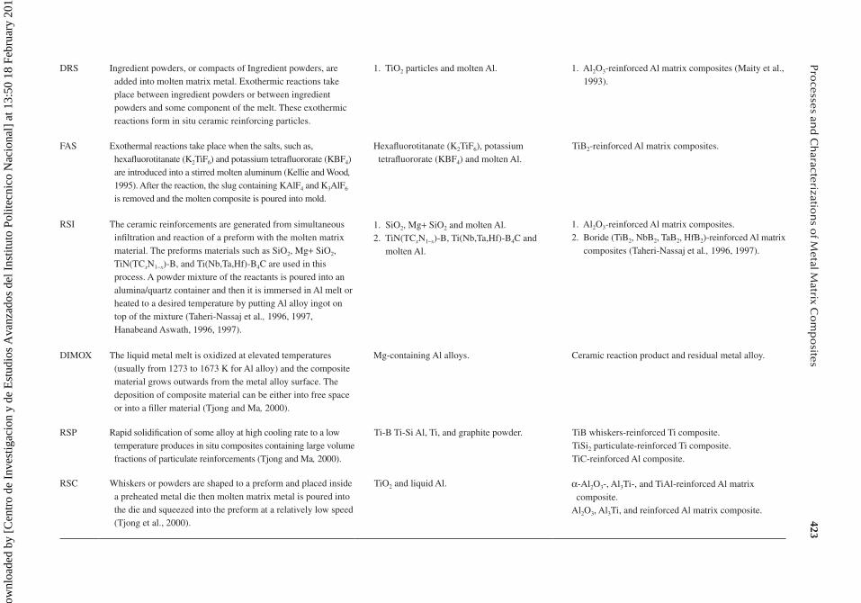
DRS Ingredient powders, or compacts of Ingredient powders, are added into molten matrix metal. Exothermic reactions take place between ingredient powders or between ingredient powders and some component of the melt. These exothermic reactions form in situ ceramic reinforcing particles.
1. TiO2 particles and molten Al. 1. Al2O3-reinforced Al matrix composites (Maity et al., 1993).
FAS Exothermal reactions take place when the salts, such as, hexafluorotitanate (K2TiF6) and potassium tetrafluororate (KBF4) are introduced into a stirred molten aluminum (Kellie and Wood, 1995). After the reaction, the slug containing KAlF4 and K3AlF6 is removed and the molten composite is poured into mold.
Hexafluorotitanate (K2TiF6), potassium tetrafluororate (KBF4) and molten Al.
TiB2-reinforced Al matrix composites.
RSI The ceramic reinforcements are generated from simultaneous infiltration and reaction of a preform with the molten matrix material. The preforms materials such as SiO2, Mg+ SiO2, TiN(TCxN1−x)-B, and Ti(Nb,Ta,Hf)-B4C are used in this process. A powder mixture of the reactants is poured into an alumina/quartz container and then it is immersed in Al melt or heated to a desired temperature by putting Al alloy ingot on top of the mixture (Taheri-Nassaj et al., 1996, 1997, Hanabeand Aswath, 1996, 1997).
1. SiO2, Mg+ SiO2 and molten Al.2. TiN(TCxN1–x)-B, Ti(Nb,Ta,Hf)-B4C and
molten Al.
1. Al2O3-reinforced Al matrix composites.2. Boride (TiB2, NbB2, TaB2, HfB2)-reinforced Al matrix
composites (Taheri-Nassaj et al., 1996, 1997).
DIMOX The liquid metal melt is oxidized at elevated temperatures (usually from 1273 to 1673 K for Al alloy) and the composite material grows outwards from the metal alloy surface. The deposition of composite material can be either into free space or into a filler material (Tjong and Ma, 2000).
Mg-containing Al alloys. Ceramic reaction product and residual metal alloy.
RSP Rapid solidification of some alloy at high cooling rate to a low temperature produces in situ composites containing large volume fractions of particulate reinforcements (Tjong and Ma, 2000).
Ti-B Ti-Si Al, Ti, and graphite powder. TiB whiskers-reinforced Ti composite.TiSi2 particulate-reinforced Ti composite.TiC-reinforced Al composite.
RSC Whiskers or powders are shaped to a preform and placed inside a preheated metal die then molten matrix metal is poured into the die and squeezed into the preform at a relatively low speed (Tjong et al., 2000).
TiO2 and liquid Al. α-Al2O3-, Al3Ti-, and TiAl-reinforced Al matrix composite.
Al2O3, Al3Ti, and reinforced Al matrix composite.
Dow
nloa
ded
by [
Cen
tro
de I
nves
tigac
ion
y de
Est
udio
s A
vanz
ados
del
Ins
titut
o Po
litec
nico
Nac
iona
l] a
t 13:
50 1
8 Fe
brua
ry 2
015

424 Aerospace Materials Handbook
Similarly, Al-Mg alloy matrix composite reinforced with in situ AlN particulates and TiN whiskers can be produced through VLS reaction process. In that case, Al-4.5 Mg-6.2 Ti (in wt.%) alloy is melted in an induction furnace. Then the chamber is back-filled with purified argon. At a suitable processing temperature, clean N2 gas is introduced into the Al alloy melt. It is believed that an inten-sive exothermic reaction takes place and Ti atoms in the Al liquid react with the N atoms to form TiN crystal nuclei (Tjong and Ma, 2000).
8.2.4.3 Solid–Solid Reaction ProcessAs the name indicates, this method involves mixing the ingredients in solid state. This has simi-larities with powder metallurgy though reinforcements are generated through reactions among raw materials in solid–solid reaction process. Tjong and Ma (2000) divided this process into three cat-egories such as MA, reactive hot pressing (RHP), and isothermal heat treatment (IHT).
8.2.4.4 Liquid–Liquid Reaction ProcessIn this process, molten-metal streams at high speed and turbulence interact between each other and form refractory particles from chemical reactions. For example, molten streams of Cu-Ti and Cu-B are made to impinge upon one another where chemical reactions take place and TiB2 nano-particulates (50 nm) are produced in copper matrix (Lee et al., 1992).
8.2.5 other Methods
For fiber-reinforced MMCs, different processes are applied depending on the properties of matrix materials, arrangement of fibers, and requirements of the final products.
8.2.5.1 Foil–Fiber–FoilAlternately stacked layers of alloy foil (80–120 mm thick) and fiber mat are fused in foil−fiber−foil method. The fiber mat is produced either by weaving with a wire or ribbon, or the fibers are held in place with an organic binder which is outgassed before the final consolidation (Vassel, 1999). This process is most suitable for the matrix material that has a good formability and that can be obtained in the form of foil at a reasonable cost. However, this method is inappropriate for brittle matrix materials because of difficulties in fabrication of matrix foil (Subramanian et al., 1998). Another disadvantage is the existence of fibers touching, which has a detrimental effect on mechanical properties, especially fatigue crack initiation (Loh et al., 2001). Alternate to the matrix foil, thin tape caste from slurry made from the mixture of a powder matrix and organic binder may be used in this method (Loh et al., 2001).
8.2.5.2 Plasma Spray CoatingIn this method, metallic powders of matrix material are fed continuously into the plasma where they are melted and propelled at high velocity onto a single layer of reinforcement fibers wound on a drum. The matrix-coated fibers are then subsequently cut, stacked, and hot pressed to form a fully dense MMC component (Vassel, 1999). This technique requires the matrix material to be in powder form and high deposition temperatures. This may result in unacceptable levels of interstitial contamination. The crack and shrinkage-induced porosity are the natural results of this process (Subramanian et al., 1998). The presence of contaminated gas (oxygen, nitrogen) and fiber damage further deteriorate the quality of the composites. The fiber distribution in plasma-sprayed MMCs is better than the one produced by the foil−fiber−foil process.
8.2.5.3 PVD CoatingReinforcement fibers are coated with a thick layer of matrix before consolidation into a bulk com-posite in this process (Vassel, 1999). The physical vapor deposition processes by electron beam evaporation deposition (EBED) (Ward-Close and Partridge, 1990, Partridge and Ward-Close, 1993) and sputter techniques (Leucht and Dudek, 1994) are used to coat the fibers. Thus expensive alloy
Dow
nloa
ded
by [
Cen
tro
de I
nves
tigac
ion
y de
Est
udio
s A
vanz
ados
del
Ins
titut
o Po
litec
nico
Nac
iona
l] a
t 13:
50 1
8 Fe
brua
ry 2
015

425Processes and Characterizations of Metal Matrix Composites
products such as foil or powder are not required. Very uniform fiber distribution with no fibers touching can be achieved in this method. The variation of coating thickness can be used to vary the fiber volume fraction in the finished composite. Handling and consolidation are less damaging to the reinforcement in this process as each fiber is surrounded by matrix material.
When an electron beam (EB) gun is used, the rate of evaporation depends on EB gun power, source temperature, and vapor pressure of the element (Vassel, 1999). This process is attractive because of the high coating rate on the substrate (300−600 mm/h) though the metal utilization efficiency (i.e., the percentage of the metal evaporated which is collected on the fibers) is low (10%) (Partridge and Ward-Close, 1993). If the vapor pressures of elements in matrix material are very different, the com-position of the coating on the fiber may be difficult to control with a single source. At the moment, only Ti−6Al−4V alloy can be deposited with success by this method (Vassel, 1999). Among the dif-ferent sputter techniques, the triode (Leucht and Dudek, 1994) and magnetron (Subramanian et al., 1998) sputtering route have been developed for the manufacture of Ti–MMCs. Triode sputtering offers the possibility to use any matrix alloy with a precise control over the chemical composition of the coating on the fiber. Different alloys such as Ti-6-4, Ti-6-2-4-2, and IMI 834 have been deposited with success. This method has a lower deposition rate but a higher utilization efficiency if compared to the electron beam deposition process. On the other hand, magnetron sputtering shows almost simi-lar performance to that of electron beam deposition method (Subramanian et al., 1998).
The fabrication processes are chosen based on the constituents and properties of MMCs. Table 8.3 summarizes different fabrication processes, constituents, and properties of MMCs.
TABLE 8.3Fabrication Processes and MMCs
Processes Reinforcements/Matrix Main Features
Powder formingSintered aluminum
Long or short fibers or particulate incorporated by powder metallurgy
Hard metals
Mechanical alloying
Al2O3 particulate/Al matrix Moderate strength and stiffness to around 300°C
Low densityGood stiffness/strength to modest temperatures
Low densityLow thermal expansionWell-developed class of material for cutting applications
High-performance alloyHigh strength at high temperature
Al2O3, SiC in Al alloy matrix
WC particulate in Co matrix
Oxide particles in superalloy matrix
In situ forming Al2O3, SiO2, BeO particulate in Cu or Ag
Modest strength improvementGood electrical conductivity
Molten metal mix processing/casting SiC or Al2O3/light alloy matrices Modest improvements in properties
Infiltration of performs/squeeze casting
SiC whisker, Al2O3 fibers/Al alloys C/Al, and Mg alloys
SiC/Ti alloys B/Al alloys
Good stiffness and strength to 200°C (Mg), 300°C (Al), and 600°C (Ti)
Low densityLow thermal conductivity
OCC SiC particulate/in Al alloy Suitable for near net shape welding wire
Spraying Particulate/short or long fibers in alloy matrices, for example, SiC or Al2O3/in Al alloy
Good stiffness and strengthLow density low thermal expansion coefficient
Source: Adapted from Warren, R. 1988. Proc. 9th Risø Int. Sym. (Risø Press, Denmark), 233; Ralph, B., H. C. Yuen, and W. B. Lee. 1997. Journal of Materials Processing Technology 63:339–353.
Dow
nloa
ded
by [
Cen
tro
de I
nves
tigac
ion
y de
Est
udio
s A
vanz
ados
del
Ins
titut
o Po
litec
nico
Nac
iona
l] a
t 13:
50 1
8 Fe
brua
ry 2
015

426 Aerospace Materials Handbook
8.3 MECHANICAL PROPERTIES
The difference in thermal expansion coefficients between matrix and reinforcements gener-ates tensile thermal residual stresses in the metal matrix during the cooling of the fabrica-tion process and the consequent heat treatment (Fiori et al., 2000). Dislocations in the matrix unavoidably appear due to stress relaxation and matrix deformation during cooling. Stress concentration occurs near the interfaces or the tips of reinforcements. Thus, plastic deforma-tion usually begins in these regions (Peng et al., 2008). The residual stress, dislocation density, and deformation in the neighborhood of the interfaces have a great influence on the mechanical behavior of the MMCs (Hu et al., 2002, Zhang et al., 2001, Fei et al., 2003). The properties of composites are mainly dependent on the properties and percentage of reinforcement and matrix material as well as fabrication process and other treatments. Table 8.4 presents the properties and manufacturing processes of different fiber reinforcements used in MMCs. The effects of volume fraction and reinforcement direction on physical and mechanical properties of MMCs are given in Table 8.5.
The properties of particle-reinforced MMCs are generally considered to be yield strength, ulti-mate tensile strength, and ductility (McDaniels, 1985; Doel and Bowen, 1996). For a constant par-ticle volume fraction, the tensile strength tends to increase with decreasing particle size (Stephens
TABLE 8.4Properties Variation with Different Reinforcement at Room Temperature
Material and Form
Method of Preparation
Diameter (µm)
Specific Gravity
Mean Fracture
Stress (MPa)
Axial Young’s Modulus
(GPa)
Coeff. of Thermal Expansion K–1 × 10⁶
Tungsten Drawn 10–500 19.2 2500 400 5
Steel (mono/multifilament)
Drawn 10–250 7.8 2500 210 15
Boron (monofilament)
CVD 150 2.6 3500 400 8
SiC (monofilament) CVD 150 3.4 3800 450 4.5
SiC (multifilament) 2e
Pyrolysis 12 ± 3 2.6 2500 200 4.5
SiC (whisker) Pyrolysis 0.1–2 3.2 10,000 700 4.5
α-Al3O2 (multifilament)
Pyrolysis or sintering
20 ± 5 3.9 1500 380 7
δ-Al3O2 (whisker) Pyrolysis or sintering
3 ± 1 3.5 2000 300 7
Carbon (multifilament): high modulus med. strength
Pyrolysis Pyrolysis
108
21.9
30004200
600300
——
Al2O3/27%SiO2 (whisker)
Pyrolysis or sintering
3 3 850 150 —
Al2O3/27%SiO2 (whisker)
Melt 3 2.7 1750 105 —
S-glass (multifilament)
Melt 3–20 2.5 4000 90 3
Source: Adapted from Warren, R. 1988. Proc. 9th Risø Int. Sym. (Risø Press, Denmark): 233; Ralph, B., H. C. Yuen, and W. B. Lee. 1997. Journal of Materials Processing Technology 63:339–353.
Dow
nloa
ded
by [
Cen
tro
de I
nves
tigac
ion
y de
Est
udio
s A
vanz
ados
del
Ins
titut
o Po
litec
nico
Nac
iona
l] a
t 13:
50 1
8 Fe
brua
ry 2
015

427Processes and Characterizations of Metal Matrix Composites
et al., 1988, Arsenault et al., 1991). However, the relationship between particle size and other prop-erties, such as fracture toughness and fatigue resistance, does not seem to be simple (Flom and Arsenault, 1989). Some common behaviors such as the response of MMCs under compression, ten-sion, and indentation are described below.
8.3.1 CoMPression
MMCs are found more capable under compression than tension because of void initiation at the matrix−reinforcement interface under tension (Table 8.6).
The elastic modulus is almost the same in tension and compression (for short fiber-reinforced titanium). The compressive strength is much higher than the tensile strength. The onset of nonlinear deformation or the proportional limit on stress−strain curves in compression is significantly higher than in tension (Gooder and Mall, 1995). This is due to the residual tensile stress generated from the mismatch of the thermal expansion coefficients between fiber and matrix due to cooling down
TABLE 8.5Effect of Volume Fraction and Reinforcement Direction on the Physical and Mechanical Properties of MMCs (Al2O3 Fiber Reinforced in Pure Al)
Volume Fraction
Sample Condition Direction
Tensile Strength (MPa)
Young’s Modulus
Hardness (Hv)
Resistivity (10–9 Ω m)
0.08 Cold rolled LongitudinalTransverse
97108
72.378
40.7 33.035.9
Annealed LongitudinalTransverse
85.294
7387
31.8 36.835.6
0.11 Cold rolled LongitudinalTransverse
99.7116
99.4108.5
49.2 39.639.6
Annealed LongitudinalTransverse
97.3101.3
83.198.2
32.6 35.936
0.14 Cold rolled LongitudinalTransverse
90.7121
78120
51.1 40.139.9
Annealed LongitudinalTransverse
88.898
82.8103
35.8 36.839.7
Source: Adapted from Yuen, H. C., W. B. Lee, and B. Ralph. 1995. Journal of Materials Science 30:843–848.
TABLE 8.6Mechanical Properties of SCS-6/Ti-β21-S in Tension and Compression at Different Temperatures
Room Temperature 650°C
Loading Condition
Young’s Modulus (GPa)
Proportional Limit (MPa)
Ultimate Strength (MPa)
Young’s Modulus (GPa)
Proportional Limit (MPa)
Ultimate Strength (MPa)
Tension 140 65 840 80 45 400
Compression 139 850 2080 81 310 1220
Source: Adapted from Gooder, J. L. and S. Mall. 1995. Composite Structures 31:315–324.
Dow
nloa
ded
by [
Cen
tro
de I
nves
tigac
ion
y de
Est
udio
s A
vanz
ados
del
Ins
titut
o Po
litec
nico
Nac
iona
l] a
t 13:
50 1
8 Fe
brua
ry 2
015

428 Aerospace Materials Handbook
while processing MMCs (Robertson and Mall, 1994). The stress−strain curves of an MMC under compression at different temperatures are given in Figure 8.3.
Particles begin to redistribute themselves within the matrix and then realign along intense shear bands under compression with increasing levels of strain. Only a small-to-moderate realignment of particles takes place along the directions of maximum shear. Their original orientation along the as-extruded axis does not change at 25% and 50% of fracture strain (for Al alloy 2618 reinforced with 14 vol% SiCp). But at a higher strain (75% of fracture strain), a significant realignment of the reinforcement occurs, achieved mainly by the fracture of large particles (Xu and Palmiere, 1999). Figures 8.4 through 8.6 demonstrate the deformation of an MMC under compression at different temperature and strain.
The fracture of particles, specifically those having larger diameter, at elevated temperatures is not as severe as particle fracture at room temperature. This is attributed to the flow soften-ing mechanisms, such as dynamic recovery and recrystallization, that are operative at elevated temperatures. These processes effectively lower the localized stress state around the hard rein-forcement particles in the matrix. As these large particles are fractured, structural integrity is maintained by the subsequent flow of the alloy matrix in and around the newly created interface (Humphreys, 1991). The significant realignment of particles occurs when the deformation takes
20
25%εf
25%εf
25%εf
50%εf
50%εf
50%εf
75%εf
75%εf
75%εf
25°C
200°C
400°C
εf
εf
εf
40
Strain rate = 0.1 s–1
Matrix-Al alloy 2618: 2.5 wt%Cu, 1.5%Mg, 1.1%Ni, 1.1%FeReinforcement: 17 vol% SiCp
60 80True strain (%)
100 120 140 16000
100
200True
stre
ss (M
Pa)
300
400
500
600
FIGURE 8.3 Flow curves of the MMC during axisymmetric compression at 25, 200, and 400°C, where εf indicates fracture strain. (Adapted from Xu, H. and E. J. Palmiere. 1999. Composites: Part A 30:203–211.)
FIGURE 8.4 Micrograph of 14 vol% SiCp reinforced 2618Al MMC prior to deformation. (Adapted from Xu, H. and E. J. Palmiere. 1999. Composites: Part A 30:203–211.)
Dow
nloa
ded
by [
Cen
tro
de I
nves
tigac
ion
y de
Est
udio
s A
vanz
ados
del
Ins
titut
o Po
litec
nico
Nac
iona
l] a
t 13:
50 1
8 Fe
brua
ry 2
015

429Processes and Characterizations of Metal Matrix Composites
place at a strain where there is flow softening within the alloy matrix. The onset of flow soften-ing occurs at a lower level of strain with increasing temperature, thus the particle redistribution is more pronounced at a given level of strain with increasing deformation temperature, such as 50% of fracture strain at 200°C and 25% of fracture strain at 400°C (Xu and Palmiere, 1999). The extent to which the reinforcement particle diameter changes depends on the level of applied strain and deformation temperature. Particle fracturing takes place predominately around the peak flow stress. But it becomes significantly less when the alloy matrix undergoes dynamic recovery and/or recrystallization. Thus the propensity of particle fracture is related to the macroscopic flow behav-ior of the alloy matrix, initial diameter of reinforcement, flow stress of the alloy matrix, tempera-ture, and the applied strain (Xu and Palmiere, 1999). The damage mechanisms of fiber-reinforced MMCs (titanium matrix) involve the debonding of fibers in the off-axis plies, cracks in fibers, and matrix plasticity. The final failure occurs due to fracture of fibers followed by failure of matrix due to its extensive yielding (Gooder and Mall, 1995).
Similar to conventional ductile materials, linear fracture lines are obtained in MMCs (Al alloy 2124 and A1-Li 8090 reinforced with 20 wt% of particulate SiC) under compression (Jiang and Dodd, 1995). Most of the surface fractures of these materials are oblique cracks, although longitu-dinal and mixed cracks were also found on some specimens with special geometries. The fracture of the specimen starts from the free surface while shear bands forms inside the material. The plastic
FIGURE 8.5 Micrograph of 14 vol% SiCp reinforced 2618Al MMC after axisymmetric compression at room temperature at 75% of fracture strain. The fracture strain at room temperature is 0.80. (Adapted from Xu, H. and E. J. Palmiere. 1999. Composites: Part A 30:203–211.)
FIGURE 8.6 Micrograph of 14 vol% SiCp reinforced 2618Al MMC after axisymmetric compression at 400°C at 75% of fracture strain. The fracture strain at 400°C is 1.28. (Adapted from Xu, H. and E. J. Palmiere. 1999. Composites: Part A 30:203–211.)
Dow
nloa
ded
by [
Cen
tro
de I
nves
tigac
ion
y de
Est
udio
s A
vanz
ados
del
Ins
titut
o Po
litec
nico
Nac
iona
l] a
t 13:
50 1
8 Fe
brua
ry 2
015

430 Aerospace Materials Handbook
flow in MMCs with larger particle size is quite different than that in MMCs reinforced with small particles. The flow of particles with the matrix in the larger particle-reinforced MMCs is not as obvious as in those with smaller particle reinforcement. The localized flow of the matrix between particles is significant in this case. These localized flows form the macroscale shear band (45° to vertical axis), similar to that in MMCs with smaller reinforcements. The fracture in MMCs under compression is predominantly controlled by the matrix shear failure (Jiang and Dodd, 1995). A proper heat treatment can resume the original structure if the deformation is not large enough to cause any localized shear in the matrix.
8.3.2 tension
The shape of stress−strain curves for fiber-reinforced MMCs is dissimilar to that of the monolithic matrix material (Brendel et al., 2009). The tensile strength increases significantly by reinforcement with 10–20% fibers but the nature of fracture becomes brittle and it occurs at very low strain com-pared to that of matrix material (Figures 8.6 and 8.7).
The Young’s modulus also increases for such composites (Thomas and Winstone, 1999). The yield stress and the Young’s modulus of short fiber (Al2O3–SiO2 reinforced in Al–Si matrix) as well as particle (Ozben et al., 2008, Xiandong et al., 1997)-reinforced composites increase with the increase of volume percentage of reinforcement (Table 8.7). When the interface between reinforcing short fiber and metal matrix is strong, the load applied on matrix could be transferred to the short fibers through interface. The length and alignment of reinforcements affect the yield stress. MMCs with longer and properly arranged reinforcements exhibit a higher yield stress (compared to random distribution) (Peng et al., 2008). It is natural that the heat treatment will influence the property of MMCs as it does to the reference matrix material.
The increase of reinforcement particle size leads to almost a linear reduction of elongation, ultimate strength, and yield strength (Slipenyuk et al., 2004, Prasad et al., 2002). The most uniform reinforcement distribution without reinforcement clusters can be obtained at an optimum ratio of matrix to reinforcement particle size for which best tensile properties are noted. The optimum ratio depends on the properties of constituents. In cases of nonuniform particle distribution, the occur-rence of the reinforcement clusters is expected which introduce some form of initial microstructural damage. For example, the SiC clusters in the material may be considered as preexisting cracks which can support only compressive stresses (Slipenyuk et al., 2004). Particle size ratio affects
00
100
200
300
400
Stre
ss (M
Pa)
500
600
700
MMC with 20% fiber volume fraction
MMC with 10% fiber volume fraction
Copper
3 6 9Strain (%)
12 15 18
FIGURE 8.7 The stress−strain diagram of pure copper and composite material with 10% and 20% of fiber volume fraction. (Adapted from Brendel, A. et al. 2009. Journal of Nuclear Materials 386–388:837–840.)
Dow
nloa
ded
by [
Cen
tro
de I
nves
tigac
ion
y de
Est
udio
s A
vanz
ados
del
Ins
titut
o Po
litec
nico
Nac
iona
l] a
t 13:
50 1
8 Fe
brua
ry 2
015

431Processes and Characterizations of Metal Matrix Composites
tensile elongation more sensitively than tensile strength or yield strength. The response of the com-posite mechanical properties related to reinforcement clustering does not depend strongly on matrix ductility (Slipenyuk et al., 2004).
Shear band patterns similar to that of a reference matrix material in MMCs are observed when deformed under uniaxial tension, provided that reinforcements are smaller in size and in volume percentage (e.g., 10% SiC particles and 10 µm diameter in Al-6061) (Kolednik and Unterweger, 2008). Similar to a compression test, the shear bands are oriented 45° to the loading axis or the direction of maximum shear stress. But this happens only in the large particle-free regions. The deformation pattern, that is, the spacing of the shear bands in the MMC is determined by the arrangement and size of the particles. The damage-induced shear bands dominate the deformation behavior. MMCs reinforced with larger particles frac-ture at a smaller strain. With increasing the volume percentage of smaller particles (20% of 10 µm particles), the behavior of the MMC changes and its fracture mechanism becomes similar to that with large particles. In this case, particle clusters act like big particles. When the particles become bigger and the volume percentage increases to 45° (to the loading axis), damage-induced deformation bands disappear. The MMC behaves like a brittle material and the plastic deformation concentrates in a plane perpendicular to the loading axis (Kolednik and Unterweger, 2008).
Under tension, voids mainly originate at the reinforcement-rich network region in the composites having lower matrix to reinforcement particle size ratio (5:1, for Al 2124/SiCp 30 vol%). Such voids coalescece with further tension as the matrix offers a large amount of deformation prior to rupture.
TABLE 8.7Effect of Various Factors on the Tensile Properties of Al2O3–SiO2(sf)/Al–Si MMC
FactorsMacroyield Stress (MPa)
Microyield Stress (MPa)
Stress to Move the First Movable
Dislocation (MPa)Young’s
Modulus (GPa)
Volume Fraction10(%) 120 78 75 68.9
20(%) 130 53 52 71.1
30(%) 142 37 34 81.1
40(%) 165 24 23 89.8
Fiber Length60 105 58 54 —
80 117 42 35 —
120 125 30 26 —
Fiber DistributionRandom 102 48 46 —
Alignment 132 29 23.5 —
Heat TreatmentAs-cast 125 24 22.5 —
Quenched 165 20 19 —
Annealed 142 37 34 —
Aged 2 h 160 33 30 —
Aged 4 h 188 49 46 —
Aged 6 h 200 58 54 —
Source: Adapted from Peng, J. et al. 2008. Materials Science and Engineering A 486:427–432.
Dow
nloa
ded
by [
Cen
tro
de I
nves
tigac
ion
y de
Est
udio
s A
vanz
ados
del
Ins
titut
o Po
litec
nico
Nac
iona
l] a
t 13:
50 1
8 Fe
brua
ry 2
015

432 Aerospace Materials Handbook
The path of void coalescence is predominantly the interface between the matrix and network region (particle clusters). On the other hand, for the composite with higher matrix to reinforcement par-ticle size ratio (25:1, for Al 2124/SiCp 30 vol%), voids primarily initiate within the matrix grains. This suggests an inadequate load transfer from the matrix to the reinforcement network. Thus, void nucleation and coalescence of these voids occur by tensile rupturing in the particle clusters. This is also because of the small volume fraction of matrix material to deform in the network region. The fracture path is predominantly the interface between the matrix and the network region in this case (Prasad et al., 2002). All the fracture surfaces appeared to be flat, indicating predominantly brittle fracture at macrolevel though some ductile features in the form of dimples (Prasad et al., 2002). Under the macroscopic yield stress, progressive particulate cracking occurs systematically in MMCs (Kolednik and Unterweger, 2008). The progression of damage in the composite nota-bly reduces during the last stages of the tensile tests when crack growth is predominant over new damage events (Gariboldi et al., 1996). Fractured surface inspection reveals the dominance of par-ticle fracture for the solution annealed, under-aged, peak-aged, and slightly over-aged conditions of the matrix. On the other hand, interface debonding dominates in the highly over-aged condition (Pandey et al., 2000).
The tensile strength of nanosized SiC particle-reinforced MMCs is a bit higher than that with microsized particles. The smaller the grain size, the higher the required crack nucleating stress (Sharma et al., 2004). Percent elongation of MMCs with nanosized particles is lower than that of the materials with microsized particles. Dispersion of a very large number of nanosized SiC particles severely limits the movement of dislocations and decreases the ductility significantly. An increase in volume fraction of both micro- and nanosized SiC particles slightly increases the tensile strength and decreases the percent elongation. The increase in volume fraction increases the hardness sig-nificantly (Barmouz et al., 2010).
Precoating of the fibers with a suitable material may lead to a strong bonding between fiber and matrix. The weak point within the composite is the fiber itself. Fracture area analyzes after tensile tests show the failure of the fibers at the interface. The load can be transported through the matrix to the fibers via the interface. The strain of fiber and matrix is the same, but the stress of fibers is higher due to higher modulus of elasticity of reinforcements. The fibers carry the load to a point, where the fibers fail (Brendel et al., 2009).
It is noted that the Ti−6Al−4V reinforced by SiC fibers usually fail at a strain of 1%, but the failure strain of virgin SiC fibers is only 0.8%. The mechanisms for increasing the apparent fail-ure strain of the fibers are: (1) load transfer by the matrix, and (2) thermal residual stresses in the MMC (Thomas and Winstone, 1999). The tensile fracture of MMCs proceeds after fracture of brittle fiber reinforcements. Thus, the composite tensile behavior is controlled by the strain rather than by the stress. The damage of composites in tension is localized, and is close to the fracture plane which is perpendicular to the loading direction. The defect initiation starts with the fracture of several adjacent fibers (García-Leiva et al., 2003). However, at high temperatures (550°C and 600°C), damage also appears at the necking directions (35° or 55°) in a flat strip (McClintock and Argon, 1966). Thermal residual stresses are partially released at higher temperature and matrix yielding occurs at smaller stresses. Thus, at a higher temperature, matrix yielding also contributes to the failure mechanisms of the composite. These fibers usually break from the inside of the rein-forcement. Once the inside is damaged, the fracture progresses outwards and a pancake structure appears at the reinforcement bulk. It was reported that the residual stresses at the matrix/fiber interface decrease with the increase of temperatures (Chandra and Ghonem, 2001, García-Leiva et al., 2003). The ductility of MMCs can be increased significantly by laminating with a suitable alloy (Syn et al., 1996).
The solution treatment improves anisotropic tensile properties of particulate-reinforced MMCs. Increasing the solution temperature and time from a conventional solution treatment initially improves the mechanical properties. The optimum solution treatment for the MMC of 17.8 vol% SiCp/2124 Al is 6 h 33 min at 546°C. The effect of solution treatment time on tensile properties of
Dow
nloa
ded
by [
Cen
tro
de I
nves
tigac
ion
y de
Est
udio
s A
vanz
ados
del
Ins
titut
o Po
litec
nico
Nac
iona
l] a
t 13:
50 1
8 Fe
brua
ry 2
015

433Processes and Characterizations of Metal Matrix Composites
this MMC is given in Table 8.8. If the solution treatment temperature and time are more than the optimum values the mechanical properties deteriorate due to gas porosity and surface blistering (Thomas and King, 1996).
The tensile properties of some commonly used MMCs and their matrix materials are presented in Table 8.9. This reveals the improvement of the tensile properties of MMCs due to reinforcements and heat treatments.
8.3.3 indentation
Indentation tests are cheap and quick to investigate the deformation mechanisms of MMCs. An earlier investigation on the indention of an MMC was performed by Leggoe et al. (1994), using both pyramid and spherical indenters. It was found that the hardness of matrix in MMC (Al6061/20%Micral) was higher than that of monolithic 6061 aluminum alloy. The load−displacement curve of microindention process shows deviation at different stages during loading. Figure 8.8 shows the load−displacement
TABLE 8.8Effect of Solution Treatment Time on the Tensile Properties of 17.8 vol% SiCp/2124 Al
Solution Treatment Time (h) σ02% (MPa)
σuts (MPa) εf(%) E(GPa) Hv
1 445 667 7.8 94 191
2 447 670 8.5 96 193
4 446 670 9.4 101 194
8 447 678 11.0 99 191
12 441 675 10.5 96 191
16 430 640 9.1 91 190
Source: Adapted from Thomas, M. P. and J. E. King. 1996. Composites Science and Technology 56:1141–1149.
TABLE 8.9The Tensile Properties of Some Composites and Unreinforced Alloys
Alloy Type and Reinforcement
Heat Treatment Condition
Young’s Modulus (GPa)
0.2% Proof Stress (MPa)
Tensile Strength (MPa) Elongation (%)
2014 Al Solution treated — 153 402 21.7
2014 Al + SiC Solution treated — 210 406 11.5
2014 Al T6 73.8 432 482 10.2
2014 Al + SiC T6 93.8 437 489 7.4
2014 Al + SiC T8 — 484 521 8.7
Al-3.5%Cu T4 68.6 150 233 19.5
Al-3.5%Cu +Al2O3 T4 90.9 134 319 2.3
Al-3.5%Cu T6 70.6 174 261 14.0
Al-3.5%Cu +Al2O3 T6 95.4 238 374 2.2
Source: Adapted from Harris, S. J., et al. 1988. In: Proc. 9th Risø Int.Sym. (Risø Press, Denmark): 373; Ralph, B., H. C. Yuen, and W. B. Lee. 1997. Journal of Materials Processing Technology 63:339–353.
Dow
nloa
ded
by [
Cen
tro
de I
nves
tigac
ion
y de
Est
udio
s A
vanz
ados
del
Ins
titut
o Po
litec
nico
Nac
iona
l] a
t 13:
50 1
8 Fe
brua
ry 2
015

434 Aerospace Materials Handbook
curves from a finite element analysis for different location of indentation relative to reinforcement (LIRP), such as those due to indentation just above the particle (IAP) and at the middle of particles (IMP). This is the total displacement of the indenter in the work material. The load–displacement curves are related to the elastic modulus and hardness of the work material. Compared with a mono-lithic material, it is more difficult to interpret them in terms of hardness, tensile strength, ultimate strength, and modulus of elasticity (Mussert et al., 2002). For example, the gradient of the force–dis-placement curves (Figure 8.8) varies with indentation load, LIRP, size ratio of indenter to particle (SRIP), and so on.
Figure 8.8 shows that the load–displacement curves for IAP and IMP bifurcate, and the IAP shows a higher gradient. There are two obvious changes along the load–displacement curves, at points A and B for IAP & A and F for IMP. This phenomenon was experimentally observed by Mussert et al. (2002), and was simply attributed to the presence of particles. During unloading, curves for IAP and IMP followed similar trend of elastic recovery, although the gradient of IAP curve is higher than that of the IMP. At a given load after complete unloading, the residual plastic deformation for IAP is smaller than that of the IMP. Initially, the effect of LIRP is negligible for both cases (part OA along the curves). After point A, the matrix between indenter and particles experiences high deformation. This results in a trend change in the load–displacement curve. For the IMP, the restriction to matrix flow by particle is less and the indentation displacement is higher than those for the IAP under the same indentation load. Hence, AB shows a higher gradi-ent than AF. At B and F, secondary indentation starts to take place, that is, reinforcement particles start to act as indenters. Consequently, the force–displacement curves indicate a further increase of gradient. Higher load-bearing capacity of reinforced particles reduces the deformation of the MMC under loading (Shen et al., 2001a). The total deformation of the MMC for IAP is lower than that of IMP at a given indentation load because in this case the particle is located closer to the indenter. For the same reason, in case of the IAP, the particle carries a higher load and the matrix deformation is lower than that of the IMP. After unloading, the elastic particle will return to its undeformed form but plastic matrix will remain deformed. Hence, higher plastic deformation is noted during the IMP.
Volume percentage of reinforced particles plays a very important role in the properties of an MMC. Figures 8.9a and b present the load–displacement responses during loading and unloading for different volume percentages of reinforcements for both the IAP and IMP. At the start of the indentations, all the curves show almost the same trend but with further loading, they indicate vary-ing gradient.
00
0.05
Load
(N)
0.1
0.15
0.2
0.25
0.3
0.35 OABCDE—for IAPOAFGHI—for IMP C G
HDFB
OA
IE
0.001 0.002Displacement (mm)
0.003 0.004 0.005
FIGURE 8.8 Load–displacement curves for different LIRP (SRIP = 1 and particle volume% = 20). (Adapted from Pramanik, A., L. C. Zhang, and J. A. Arsecularatne. 2008a. Composites Science and Technology 68:1304–1312.)
Dow
nloa
ded
by [
Cen
tro
de I
nves
tigac
ion
y de
Est
udio
s A
vanz
ados
del
Ins
titut
o Po
litec
nico
Nac
iona
l] a
t 13:
50 1
8 Fe
brua
ry 2
015

435Processes and Characterizations of Metal Matrix Composites
The gradient increment depends on the volume percentage of reinforcement and LIRP. The higher the volume percentage of reinforcements, the higher is the gradient increment. After unloading, lower plastic deformation is noted for the MMC with a higher volume percentage of reinforcement.
A loading curve with a higher gradient indicates that a higher load is required for a given depth of indentation, that is, higher resistance to deformation. An increase of the volume percentage of particles means a decrease of the volume percentage of the matrix material and hence an increase of particle number (for a constant particle size). Hence, an increased number of particles will take part in resisting matrix flow and carrying loads in the composite. Thus, it is clear that with the increase of volume percentage of reinforcements, resistance to deformation increases, that is, the loading curves show a greater gradient. The above mechanism will make an MMC with a higher volume percentage of reinforcements that shows lower plastic deformation. These are also affected by the LIRP due to the variation of distance between the indenter and particle. It seems that the ceramic particles increase the Young’s modulus and decrease plasticity of MMCs.
Particle size as well as indenter size have a significant effect on deformation behavior of MMCs during indentation. The effects of these two parameters can be accounted by considering the size ratio of indenter to particle. Figures 8.10a and b show the effects of this ratio on the behavior of load–displacement curves for the two types of LIRP. Similar to the effects of volume percentage of reinforcements discussed earlier, at the start of indentation, the gradients of load–displacement curves are similar for each case. But with the increase in indentation load, the curves start to devi-ate at different stages of loading. A load–displacement curve corresponding to a higher SRIP shows higher gradient (Figures 8.10a and b). Once again the load–displacement curves for the IAP case show higher gradient compared to those for IMP case. Thus, it is clear that resistance of an MMC to deformation increases with the increase of SRIP.
For the ranges of forces/displacements investigated (Pramanik et al., 2008), after unloading, almost constant plastic deformation is noted for all the SRIP considered (Figures 8.10a and b) but plastic deformation of MMC is higher for IMP than that of IAP. This indicates that, for the presented range of loads, and so on the size of indenter has negligible influence on plastic deforma-tion (depth) of MMCs. With the increase of indenter diameter, a larger contact area and hence a higher resistance due to reinforced particles is encountered by the indenter at a given indentation load. Therefore, total deformation of an MMC decreases with the increase of SRIP (Figure 8.10). Consequently, a load–displacement curve shows higher gradient at higher SRIP. It is noted that
0 0.001 0.002 0.003 0.004 0.005 0.0060
0.05
Load
(N)
0.1
0.15
0.2
0.25
0.3
0.351
1
2
2
3
3
43020100
4
Curve number:Particle vol%:
Displacement (mm)0 0.001 0.002 0.003 0.004 0.005 0.006
0
0.05
Load
(N)
0.1
0.15
0.2
0.25
0.3
0.351
1
2
2
3
3
43020100
4
Curve number:Particle vol%:
Displacement (mm)
(a) (b)
FIGURE 8.9 Effects of reinforced particle volume percentage on load–displacement curves (SRIP = 1) (a) IAP; (b) IMP. (Adapted from Pramanik, A., L. C. Zhang, and J. A. Arsecularatne. 2008a. Composites Science and Technology 68:1304–1312.)
Dow
nloa
ded
by [
Cen
tro
de I
nves
tigac
ion
y de
Est
udio
s A
vanz
ados
del
Ins
titut
o Po
litec
nico
Nac
iona
l] a
t 13:
50 1
8 Fe
brua
ry 2
015

436 Aerospace Materials Handbook
the variation of total deformation of an MMC is low with the variation of SRIP considered in this investigation. Hence, there is no significant variation of plastic deformation.
The response of particles in Al 359/SiC and Al 6061/Micral, and that of the particle/matrix interface in Al 359/SiC are different. The ceramic particles increase the MMC’s ability to resist deformation, but this is highly dependent on the location of indentation relative to particles, vol-ume percentage of particles, size ratio of indenter to particle and applied load. Consequently, these parameters affect hardness of MMCs (Pramanik et al., 2008). The hardness of MMC is higher than that of the matrix material because particles limit the plastic flow of the matrix. Stiffer rein-forcement particles close to indenter also generate secondary effect on the more compliant matrix (Leggoe, 2004).
Hardness of a material obtained by indentation is a measure of its resistance to plastic deforma-tion. Microhardness of an MMC, compared to a monolithic material, may show greater depen-dency on indentation load because of its inhomogeneous deformation behavior due to the presence of reinforcement particles. For the two types of LIRP, variation of hardness at various stages of loading is obvious. Figure 8.11 demonstrates that the microhardness of MMC is dependant on the
0 0.001 0.002 0.0030
0.05
Load
(N)
0.1
0.15
0.2
0.25
0.31 10.8
1.01.21.4
22
3
3
4
4 12340.35 Curve number SRIP
Displacement (mm)
(a)
0 0.001 0.002 0.003 0.004 0.0050
0.05
Load
(N)
0.1
0.15
0.2
0.25
0.3 1 0.81.01.21.4
234
0.35 Curve number SRIP
Displacement (mm)
(b)
FIGURE 8.10 Effects of the SRIP on the load–displacement curves (particle volume% = 20) (a) IAP; (b) IMP. (Adapted from Pramanik, A., L. C. Zhang, and J. A. Arsecularatne. 2008a. Composites Science and Technology 68:1304–1312.)
01500
3000
4500
Har
dnes
s (M
Pa)
6000
7500
9000 ABCMN—for IAPAFGPQ—for IMP
A
C
N
Q
PGB
F
M
0.25 0.5 0.75Load (N)
1 1.25
FIGURE 8.11 Effects of indentation load on the hardness of MMC (size ratio of indenter to particle = 1 and particle volume% = 20). (Adapted from Pramanik, A., L. C. Zhang, and J. A. Arsecularatne. 2008a. Composites Science and Technology 68:1304–1312.)
Dow
nloa
ded
by [
Cen
tro
de I
nves
tigac
ion
y de
Est
udio
s A
vanz
ados
del
Ins
titut
o Po
litec
nico
Nac
iona
l] a
t 13:
50 1
8 Fe
brua
ry 2
015
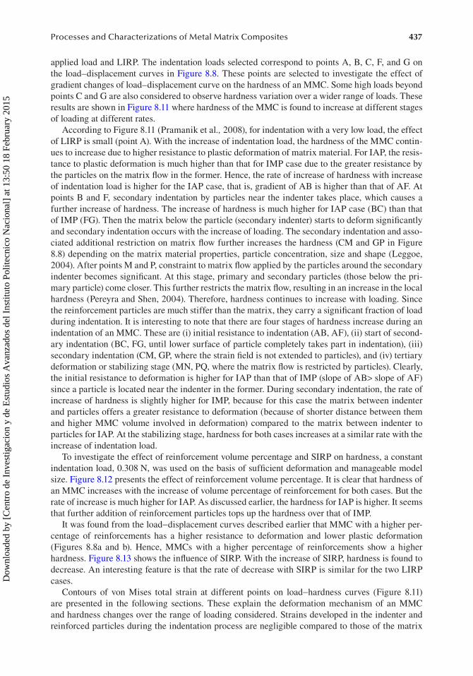
437Processes and Characterizations of Metal Matrix Composites
applied load and LIRP. The indentation loads selected correspond to points A, B, C, F, and G on the load–displacement curves in Figure 8.8. These points are selected to investigate the effect of gradient changes of load–displacement curve on the hardness of an MMC. Some high loads beyond points C and G are also considered to observe hardness variation over a wider range of loads. These results are shown in Figure 8.11 where hardness of the MMC is found to increase at different stages of loading at different rates.
According to Figure 8.11 (Pramanik et al., 2008), for indentation with a very low load, the effect of LIRP is small (point A). With the increase of indentation load, the hardness of the MMC contin-ues to increase due to higher resistance to plastic deformation of matrix material. For IAP, the resis-tance to plastic deformation is much higher than that for IMP case due to the greater resistance by the particles on the matrix flow in the former. Hence, the rate of increase of hardness with increase of indentation load is higher for the IAP case, that is, gradient of AB is higher than that of AF. At points B and F, secondary indentation by particles near the indenter takes place, which causes a further increase of hardness. The increase of hardness is much higher for IAP case (BC) than that of IMP (FG). Then the matrix below the particle (secondary indenter) starts to deform significantly and secondary indentation occurs with the increase of loading. The secondary indentation and asso-ciated additional restriction on matrix flow further increases the hardness (CM and GP in Figure 8.8) depending on the matrix material properties, particle concentration, size and shape (Leggoe, 2004). After points M and P, constraint to matrix flow applied by the particles around the secondary indenter becomes significant. At this stage, primary and secondary particles (those below the pri-mary particle) come closer. This further restricts the matrix flow, resulting in an increase in the local hardness (Pereyra and Shen, 2004). Therefore, hardness continues to increase with loading. Since the reinforcement particles are much stiffer than the matrix, they carry a significant fraction of load during indentation. It is interesting to note that there are four stages of hardness increase during an indentation of an MMC. These are (i) initial resistance to indentation (AB, AF), (ii) start of second-ary indentation (BC, FG, until lower surface of particle completely takes part in indentation), (iii) secondary indentation (CM, GP, where the strain field is not extended to particles), and (iv) tertiary deformation or stabilizing stage (MN, PQ, where the matrix flow is restricted by particles). Clearly, the initial resistance to deformation is higher for IAP than that of IMP (slope of AB> slope of AF) since a particle is located near the indenter in the former. During secondary indentation, the rate of increase of hardness is slightly higher for IMP, because for this case the matrix between indenter and particles offers a greater resistance to deformation (because of shorter distance between them and higher MMC volume involved in deformation) compared to the matrix between indenter to particles for IAP. At the stabilizing stage, hardness for both cases increases at a similar rate with the increase of indentation load.
To investigate the effect of reinforcement volume percentage and SIRP on hardness, a constant indentation load, 0.308 N, was used on the basis of sufficient deformation and manageable model size. Figure 8.12 presents the effect of reinforcement volume percentage. It is clear that hardness of an MMC increases with the increase of volume percentage of reinforcement for both cases. But the rate of increase is much higher for IAP. As discussed earlier, the hardness for IAP is higher. It seems that further addition of reinforcement particles tops up the hardness over that of IMP.
It was found from the load−displacement curves described earlier that MMC with a higher per-centage of reinforcements has a higher resistance to deformation and lower plastic deformation (Figures 8.8a and b). Hence, MMCs with a higher percentage of reinforcements show a higher hardness. Figure 8.13 shows the influence of SIRP. With the increase of SIRP, hardness is found to decrease. An interesting feature is that the rate of decrease with SIRP is similar for the two LIRP cases.
Contours of von Mises total strain at different points on load−hardness curves (Figure 8.11) are presented in the following sections. These explain the deformation mechanism of an MMC and hardness changes over the range of loading considered. Strains developed in the indenter and reinforced particles during the indentation process are negligible compared to those of the matrix
Dow
nloa
ded
by [
Cen
tro
de I
nves
tigac
ion
y de
Est
udio
s A
vanz
ados
del
Ins
titut
o Po
litec
nico
Nac
iona
l] a
t 13:
50 1
8 Fe
brua
ry 2
015
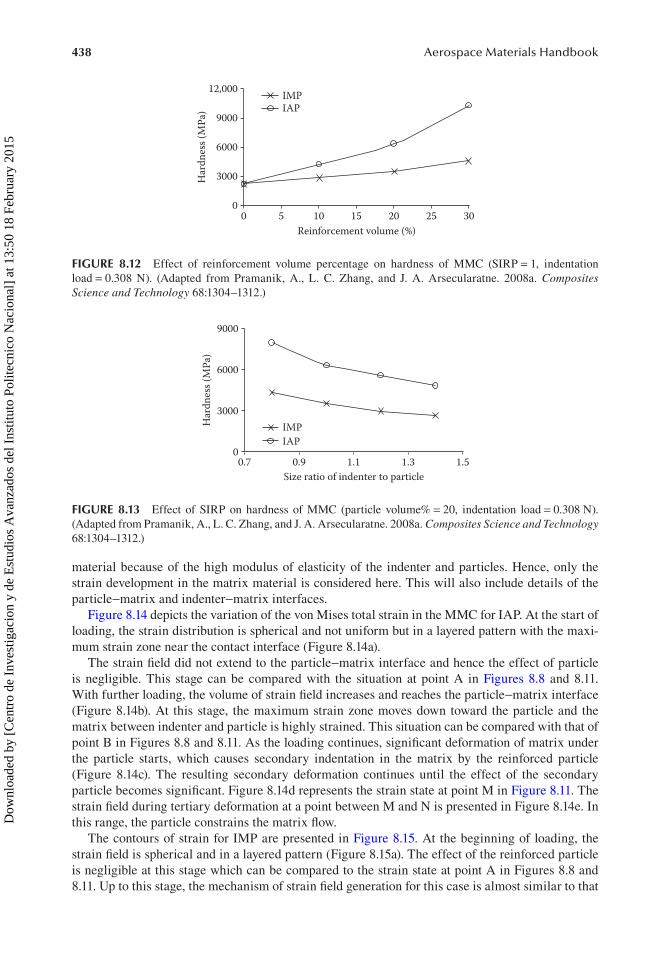
438 Aerospace Materials Handbook
material because of the high modulus of elasticity of the indenter and particles. Hence, only the strain development in the matrix material is considered here. This will also include details of the particle−matrix and indenter−matrix interfaces.
Figure 8.14 depicts the variation of the von Mises total strain in the MMC for IAP. At the start of loading, the strain distribution is spherical and not uniform but in a layered pattern with the maxi-mum strain zone near the contact interface (Figure 8.14a).
The strain field did not extend to the particle−matrix interface and hence the effect of particle is negligible. This stage can be compared with the situation at point A in Figures 8.8 and 8.11. With further loading, the volume of strain field increases and reaches the particle−matrix interface (Figure 8.14b). At this stage, the maximum strain zone moves down toward the particle and the matrix between indenter and particle is highly strained. This situation can be compared with that of point B in Figures 8.8 and 8.11. As the loading continues, significant deformation of matrix under the particle starts, which causes secondary indentation in the matrix by the reinforced particle (Figure 8.14c). The resulting secondary deformation continues until the effect of the secondary particle becomes significant. Figure 8.14d represents the strain state at point M in Figure 8.11. The strain field during tertiary deformation at a point between M and N is presented in Figure 8.14e. In this range, the particle constrains the matrix flow.
The contours of strain for IMP are presented in Figure 8.15. At the beginning of loading, the strain field is spherical and in a layered pattern (Figure 8.15a). The effect of the reinforced particle is negligible at this stage which can be compared to the strain state at point A in Figures 8.8 and 8.11. Up to this stage, the mechanism of strain field generation for this case is almost similar to that
00
3000Har
dnes
s (M
Pa)
6000
12,000 IMPIAP
9000
5 10 15Reinforcement volume (%)
20 25 30
FIGURE 8.12 Effect of reinforcement volume percentage on hardness of MMC (SIRP = 1, indentation load = 0.308 N). (Adapted from Pramanik, A., L. C. Zhang, and J. A. Arsecularatne. 2008a. Composites Science and Technology 68:1304–1312.)
00.7 0.9
IAPIMP
1.1Size ratio of indenter to particle
1.3 1.5
3000
Har
dnes
s (M
Pa)
6000
9000
FIGURE 8.13 Effect of SIRP on hardness of MMC (particle volume% = 20, indentation load = 0.308 N). (Adapted from Pramanik, A., L. C. Zhang, and J. A. Arsecularatne. 2008a. Composites Science and Technology 68:1304–1312.)
Dow
nloa
ded
by [
Cen
tro
de I
nves
tigac
ion
y de
Est
udio
s A
vanz
ados
del
Ins
titut
o Po
litec
nico
Nac
iona
l] a
t 13:
50 1
8 Fe
brua
ry 2
015

439Processes and Characterizations of Metal Matrix Composites
described in the last section qualitatively; but the developed strains at the corresponding points are considerably lower than those of IAP. As the loading progresses, the volume covered by the strain field increases and reaches the boundaries of particles (Figure 8.15b). It is interesting to note that, initially, the point with the maximum straining appears near the indenter (Figure 8.15a), but with continued loading it moves toward the particle and reaches the particle−matrix interface. Secondary
(a) (b)
(d)(c)
(e)
Secondary indentationTertiarydeformation
Location ofsecondaryparticle
.028135
.031652
.200-06 .649-05
.234-04 .922-04
.140-03
.305083
.610026
.9149691.221.5251.832.1352.442.745
.501973
.7529141.0041.2551.506
2.0082.259
1.757
.251033.173263.346503.519743.692983.8662231.0391.2131.3861.559
.093766
.187526
.281286
.375046
.468805
.562565
.843844
.750085
.656325
.003517
.007034
.010551
.014068
.017584
.021101
.024618
FIGURE 8.14 (See color insert.) Von Mises total strain in the matrix for IAP (SIRP = 1 and particle vol-ume% = 20). (a) At point A; (b) At point B; (c) At point C; (d) At point M; (e) In between points M and N. (Adapted from Pramanik, A., L. C. Zhang, and J. A. Arsecularatne. 2008a. Composites Science and Technology 68:1304–1312.)
Dow
nloa
ded
by [
Cen
tro
de I
nves
tigac
ion
y de
Est
udio
s A
vanz
ados
del
Ins
titut
o Po
litec
nico
Nac
iona
l] a
t 13:
50 1
8 Fe
brua
ry 2
015

440 Aerospace Materials Handbook
indentation then starts and the strain state corresponds to that at point F (Figure 8.15b). The same phenomenon was noted for the IAP case discussed above. With further loading, the matrix material passes through secondary and tertiary deformation states as shown in Figures 8.14c and d respec-tively in a manner similar to that described in the last section. These results demonstrate the effect of reinforcement particles on deformation of the matrix material and hardness of an MMC.
Tertiarydeformation
Location ofsecondaryparticle
(a)
(c)
(e)
(d)
(b)
.386-06 .166-04
.924-04
.417-03
.182478
.364539
.5466
.728661
.9107221.0931.2751.4571.639
.270-03
.173225
.346179
.519133
.692088
.8650421.0381.2111.3841.557
.108144
.216195
.324246
.432297
.540348
.648399
.75645
.864501
.972553
.058786
.117555
.176324
.235094
.293863
.352632
.411401
.470171
.52894
.002788
.005577
.008365
.011153
.013941
.016729
.019517
.022305
.025093
FIGURE 8.15 (See color insert.) Von Mises total strain in the matrix for IMP (SIRP = 1 and particle vol-ume% = 20). (a) At point A; (b) At point F; (c) At point G; (d) At point P; (e) In between P and Q. (Adapted from Pramanik, A., L. C. Zhang, and J. A. Arsecularatne. 2008a. Composites Science and Technology 68:1304–1312.)
Dow
nloa
ded
by [
Cen
tro
de I
nves
tigac
ion
y de
Est
udio
s A
vanz
ados
del
Ins
titut
o Po
litec
nico
Nac
iona
l] a
t 13:
50 1
8 Fe
brua
ry 2
015

441Processes and Characterizations of Metal Matrix Composites
The mechanisms of the anisotropy of MMCs are: varied restriction to matrix flow by particles and nonuniform work hardening of matrix material depending on the combination of the above-mentioned parameters (Pramanik et al., 2008). However, no significant difference in the mechani-cal behavior of the MMC matrix material in comparison with the reference matrix materia is noted (Mussert et al., 2002). A distinct increase of reinforcement particle concentration is induced by the indentation under the indenter. The finite element analysis showed a qualitative agreement with the experimental measurement of the particle concentration (Pereyra and Shen, 2004, 2005). A com-pressive residual stress field remained in the material after unloading (Hung et al., 1996).
Unlike monolithic metals, a simple relationship between macrohardness and tensile strength is not available. The reinforcement fraction and matrix strength appear to play an important role in influencing the behavior of the composite under hardness and tensile loading conditions (Shen et al., 2000, 2001a, Shen and Chawla, 2001b). A local increase in particle concentration directly under-neath the indenter resulted in a significant overestimation of the tensile strength by the hardness test, especially when the matrix strength was relatively low. It was found that the correlation was affected by strain hardening and particle fracture. The Vickers hardness value (in kg mm−2) was equivalent to 0.3 times the compressive flow stress (MPa) at small strain (1–2%) for high strength matrix com-posites and at large strain (4–7%) for low strength matrix composites (Shen et al., 2000, 2001a, Shen and Chawla, 2001b). This strain increases with the material’s strain-hardening exponent. A similar correlation is observed in tension. Particle fracture had little effect on the strain-hardening rate of the material. It was argued that particle fracture introduced during fabrication of MMC may have a deleterious effect on the hardness/tensile flow stress correlation while the effect of damage devel-oped during the tensile deformation is more limited. For most cases, the use of hardness to predict the tensile flow stress was likely to lead to significant overestimation (Caceres and Poole, 2002).
Owing to the presence of reinforcements, MMCs behave very differently compared to mono-lithic metals during deformation. While micro-indentation is simple to carry out, the test results at low indentation loads should be interpreted carefully because the microscopic deformation pro-cesses are complex. The micro-indentation test under low load cannot give a consistent measure of the hardness of MMCs (Pramanik et al., 2008). Particle fracture and interface debonding play sig-nificant roles in the fracture process of MMCs. Fracture of SiC particles in the composites initiates in the form of radial cracks and complete fracture occurs when the cracks reach the particle edge or some critical size. It was argued that the particle–matrix interface in the composite debonds readily under the tensile and shearing loads (Leggoe, 2004).
8.4 MACHINABILITY
8.4.1 turning
Owing to the presence of reinforcement in the matrix, deformation behavior of MMCs is complex and only a relatively small number of investigations (which include experimental, analytical, and numeri-cal investigations) on the MMC machining mechanisms has been reported. In order to minimize the machining cost and carry out machining process efficiently, modeling the machining mechanism is crucial. During machining of MMCs, short and long chips are formed which depend on the cutting conditions and constituents of the materials. Sharp tools, in particular those made of diamond, pro-duce long chips but blunt or worn tools produce short chips (Lin et al., 1995). Generally at low feeds (0.05–0.1 mm/rev), speeds in the range of 100–800 m/min and depth of cut from 0.25 to 1 mm result in long chips during machining of an Al reinforced by 20 vol%SiC particles by a sharp diamond tool (Pramanik et al., 2008b). Chips undergo very severe plastic deformation in the shear zones.
Compared to the nonreinforced alloy, chips of different shapes were noted during machining of the MMC. The types of chips formed are related to the material properties and cutting parameters such as speed, feed, and so on (Jawahir, 1990). Effect of reinforcement particles on chip shape under different machining parameters is discussed in the following sections (Pramanik et al., 2008b).
Dow
nloa
ded
by [
Cen
tro
de I
nves
tigac
ion
y de
Est
udio
s A
vanz
ados
del
Ins
titut
o Po
litec
nico
Nac
iona
l] a
t 13:
50 1
8 Fe
brua
ry 2
015

442 Aerospace Materials Handbook
For the MMC, chip shapes vary over the considered range of feeds as shown in Figure 8.16. At feed 0.025 mm/rev, chips were very short and irregular in shape. With the increase of feed, long chips were formed. At feeds 0.05 and 0.1 mm/rev, long spiral and straight chips, respectively, were observed. With further increase of feed (0.2 and 0.4 mm/rev), all chips became short and of C-shape. Though at medium feeds chips were very long, it did not entangle with the tool or work-piece and it was easily breakable. For the nonreinforced alloy, it is found that in general, the chip shape did not change significantly with the increase of feed (Figure 8.17). At all feeds, chips were long, little twisted, and had a tendency to entangle with the tool and workpiece which damaged the newly generated surface.
With the variation of cutting speed, very long and brittle chips were formed for MMC (Figure 8.18). At lower speed (100 and 200 m/min), all the chips were of spiral shape but at higher speeds chips became straight (400 and 600 m/min). With further increase of speed (800 m/min), some tightly curled chips were formed together with long straight chips. For the nonreinforced alloy, at all cutting speeds, chips were long and large spirals which entangled with the workpiece and tool (Figure 8.17).
Continuous chips are forced to curl during formation due to unequal strain occurring across the plastic zone (Oxley, 1962). The curl depends on ductility/brittleness of the chips. Chips of brittle materials have little or no tendency to curl but those of ductile materials may form long spiral chips. The shapes of chips are influenced by the uniformity of deformation and shear localization (Ng and Aspinwall, 2002). During deformation of the MMC, stress concentrations and local deformations are experienced due to presence of reinforced particles (Pramanik et al., 2007, 2008). As MMC experiences high strain while passing through the primary and secondary shear zones, some par-ticles are debonded initiating cracks and work hardening the matrix material (Hung et al., 1998, Ozcatalbas, 2003b, Pramanik et al., 2007). This makes chips brittle and easy to fracture, resulting in the formation of short chips. At lower feed, deformation of chip is more homogeneous across its thickness which may lead to formation of longer chips. But it seems that if feed is very low, chips
FIGURE 8.16 Chips of the MMC at different feeds (speed 400 m/min, depth of cut 1 mm). (Adapted from Pramanik, A., L. C. Zhang, and J. A. Arsecularatne. 2008b. International Journal of Machine Tools & Manufacture 48:1613–1625.)
Dow
nloa
ded
by [
Cen
tro
de I
nves
tigac
ion
y de
Est
udio
s A
vanz
ados
del
Ins
titut
o Po
litec
nico
Nac
iona
l] a
t 13:
50 1
8 Fe
brua
ry 2
015

443Processes and Characterizations of Metal Matrix Composites
become very thin which may break due to failure of highly strained particle−matrix interface. On the other hand, at higher feed, considerable nonhomogeneous deformation occurs due to higher cut/chip thickness which contributes to generation of shorter chips. Similarly at low cutting speed, strain rate effect is prominent which may cause inhomogeneous deformation resulting in the forma-tion of spiral chips but with the increase of speed thermal effects may reduce the inhomogeneous deformation of chips and increase the ductility of matrix (El-Gallab and Sklad, 1998b) which pro-duces straight chips.
All the chips formed during machining of the nonreinforced alloy were long and ductile because of its high ductility and deformation without formation of cracks due to absence of particles.
A harder material generally exhibits better chip disposability and shorter chips with brittle frac-ture in the chips as well as on the machined surface. On the other hand, ductile material produces very long chips with poor disposability. Long chips damage the newly generated surface. Ductile cutting with short chips are normally desired to obtain an undamaged surface (Hong et al., 1999). It seems that hard reinforcement particles in the MMC introduce disposability to highly ductile matrix material.
Formation of (small) voids/cracks due to particle debonding which coalesced to form large cracks in chip has been observed (Lin et al., 1998, Hung et al., 1999) because of the stress concentration at the edges of the particles (Joshi et al., 2001, Karthikeyan et al., 2001). However, deformation of grain boundaries along the shear plane and alignment of reinforced particles along the shear plane have also been observed (Hung et al., 1998, 1999). Thus chip formation during machining of MMCs has similarities to that of monolithic materials.
FIGURE 8.17 Chips of nonreinforced alloy at different cutting conditions (depth of cut 1 mm). (Adapted from Pramanik, A., L. C. Zhang, and J. A. Arsecularatne. 2008b. International Journal of Machine Tools & Manufacture 48:1613–1625.)
Dow
nloa
ded
by [
Cen
tro
de I
nves
tigac
ion
y de
Est
udio
s A
vanz
ados
del
Ins
titut
o Po
litec
nico
Nac
iona
l] a
t 13:
50 1
8 Fe
brua
ry 2
015
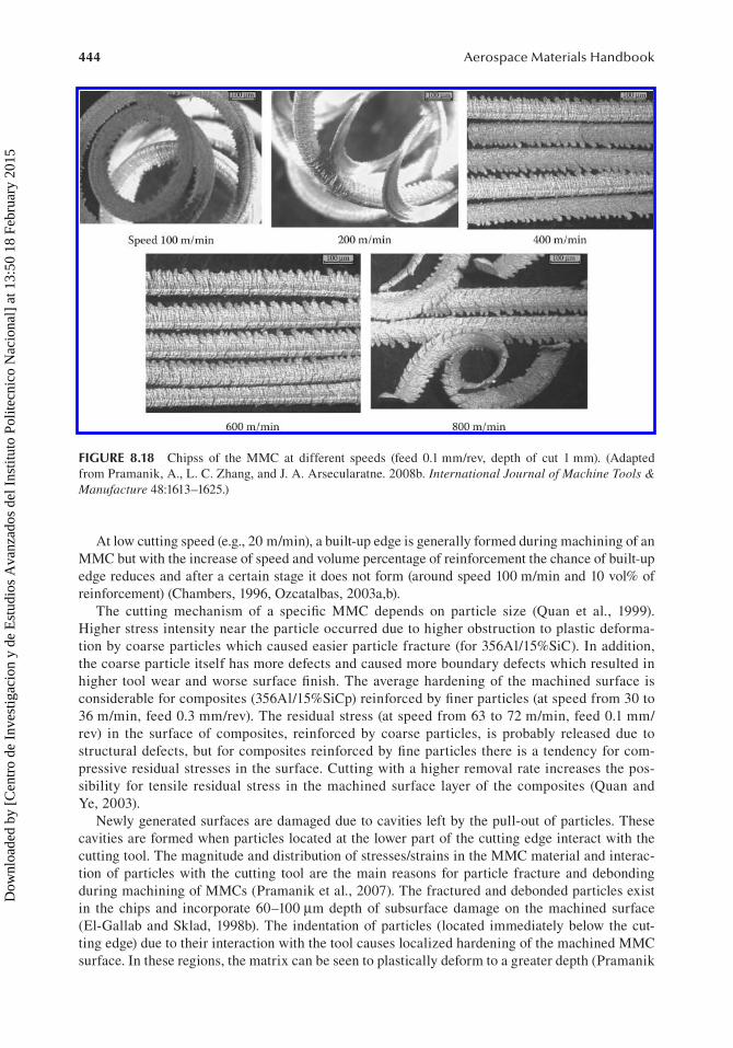
444 Aerospace Materials Handbook
At low cutting speed (e.g., 20 m/min), a built-up edge is generally formed during machining of an MMC but with the increase of speed and volume percentage of reinforcement the chance of built-up edge reduces and after a certain stage it does not form (around speed 100 m/min and 10 vol% of reinforcement) (Chambers, 1996, Ozcatalbas, 2003a,b).
The cutting mechanism of a specific MMC depends on particle size (Quan et al., 1999). Higher stress intensity near the particle occurred due to higher obstruction to plastic deforma-tion by coarse particles which caused easier particle fracture (for 356Al/15%SiC). In addition, the coarse particle itself has more defects and caused more boundary defects which resulted in higher tool wear and worse surface finish. The average hardening of the machined surface is considerable for composites (356Al/15%SiCp) reinforced by finer particles (at speed from 30 to 36 m/min, feed 0.3 mm/rev). The residual stress (at speed from 63 to 72 m/min, feed 0.1 mm/rev) in the surface of composites, reinforced by coarse particles, is probably released due to structural defects, but for composites reinforced by fine particles there is a tendency for com-pressive residual stresses in the surface. Cutting with a higher removal rate increases the pos-sibility for tensile residual stress in the machined surface layer of the composites (Quan and Ye, 2003).
Newly generated surfaces are damaged due to cavities left by the pull-out of particles. These cavities are formed when particles located at the lower part of the cutting edge interact with the cutting tool. The magnitude and distribution of stresses/strains in the MMC material and interac-tion of particles with the cutting tool are the main reasons for particle fracture and debonding during machining of MMCs (Pramanik et al., 2007). The fractured and debonded particles exist in the chips and incorporate 60–100 µm depth of subsurface damage on the machined surface (El-Gallab and Sklad, 1998b). The indentation of particles (located immediately below the cut-ting edge) due to their interaction with the tool causes localized hardening of the machined MMC surface. In these regions, the matrix can be seen to plastically deform to a greater depth (Pramanik
FIGURE 8.18 Chipss of the MMC at different speeds (feed 0.1 mm/rev, depth of cut 1 mm). (Adapted from Pramanik, A., L. C. Zhang, and J. A. Arsecularatne. 2008b. International Journal of Machine Tools & Manufacture 48:1613–1625.)
Dow
nloa
ded
by [
Cen
tro
de I
nves
tigac
ion
y de
Est
udio
s A
vanz
ados
del
Ins
titut
o Po
litec
nico
Nac
iona
l] a
t 13:
50 1
8 Fe
brua
ry 2
015

445Processes and Characterizations of Metal Matrix Composites
et al., 2007). The shear band spacing across the chip decreases with the increase of volume frac-tion of reinforcement, feed, and depth of cut. Increase of volume fraction of reinforcement and feed increases the chip disposability, chip thickness ratio, and the shear angle. Increase in speed, depth of cut and machining time resulted in decrease of chip disposability, chip thickness ratio, and the shear angle (Karthikeyan et al., 2001). At low feeds, the surface roughness of the MMCs is controlled by particle fracture and/or pull out. On the other hand, it was controlled by the feed at higher feeds (Pramanik et al., 2008b).
On the basis of the machining and indentation investigations (Pramanik et al. 2007, 2008), it was found that three factors are mainly responsible for excessive mechanical deformation on the machined surface that take over the thermal effects: (a) restriction of matrix flow due to presence of particles, (b) indentation of particles on the machined surface, and (c) high compression of matrix in between particles and tool. At a low feed, these factors become very prominent. Increased per-centage of particle fracture/debonding forces indicates higher tool−particle interaction at low feed. However, with the increase of feed, indentation effects of particles as well as tool particle interac-tion decrease for the same length of the machined workpiece. In addition, effects of temperature increase with the increase of feed. Thus, high compressive residual stresses at lower feed and lower stress values at higher feed can be expected.
The presence of hard, brittle, and abrasive SiC reinforcement makes the material difficult to form or machine using traditional manufacturing processes (Hung et al., 1995, El-Gallab and Sklad, 1998b). In order to improve machinability of the SiCp/Al composites, graphite can be added to the composites. However, with the addition of graphite particles, the mechanical properties of com-posites deteriorate, and this limits their large-scale industrial application as structure materials. Therefore, how to maintain the higher mechanical properties of SiC/Gr/Al composites has become the focus of research (Leng et al., 2008).
When a cutting tool removes a layer from the MMC workpiece, the uncut layer is first elastically deformed followed by plastic deformation and chip formation near the cutting edge of the tool. An element of material to be removed is initially under no stress when it is well ahead of the tool. As the tool approaches, the material enters a region of high strain rate where plastic deformation occurs, and becomes part of the chip. During the process of chip formation, some reinforcements in the cutting region will go into the chip, some will be debonded/fractured, and the rest will be on the machined surface. Pramanik et al. (2007) investigated the interaction between the tool and rein-forcements by categorizing it into three scenarios: particles along the cutting path, particles above the cutting path, and particles below the cutting path (Figure 8.19) (Pramanik and Zhang, 2009). All these cases, with the advancement of cutting tool during machining, are discussed in detail in the following sections.
Particles Cutting edge Cutting edge limits
Cutting direction
(a) (c)(b)
FIGURE 8.19 Particle locations with respect to the cutting path: particles (a) along, (b) above, and (c) below the cutting path. (Adapted from Pramanik, A., L. C. Zhang, and J. A. Arsecularatne. 2007. International Journal of Machine Tools and Manufacture 47:1497–1506.)
Dow
nloa
ded
by [
Cen
tro
de I
nves
tigac
ion
y de
Est
udio
s A
vanz
ados
del
Ins
titut
o Po
litec
nico
Nac
iona
l] a
t 13:
50 1
8 Fe
brua
ry 2
015

446 Aerospace Materials Handbook
8.4.1.1 Evolution of Stress Field8.4.1.1.1 Scenario 1: Particles along the Cutting PathThe orientation between tool and particle is categorized under this case if any part of a particle falls in between upper and lower limits of cutting edge as shown in Figure 8.19a. The evolution of stress fields during machining is demonstrated in Figures 8.20a−d for a particle located in the lower part of the cutting edge, that is, the center of the particle is below the center of the cutting edge. Initially the compressive and tensile stresses are perpendicular and parallel respectively to the cutting edge in the matrix and particle in front of the cutting edge. This type of stress distribu-tion may initiate fracture in the particle and debonding at the interface. With the advancement of the tool, the matrix between the upper part of the particle and tool becomes highly compressive while lower right interface of the particle becomes highly tensile (Figure 8.20a). This indicates that an anticlockwise moment is acting on the particle, thus debonding of the particle may be expected with further advancement of the tool. When tool−particle interaction occurs, significant tensile and compressive stresses that are perpendicular to each other are found in the left part of the particle (Figure 8.20b). However, the right part of the particle is only under compressive stress. Such stress distribution may initiate particle fracture if the stresses are high enough. With
FIGURE 8.20 Evolution of stress fields for particle along the cutting path during machining of MMC. Compressive and tensile stresses are represented by black >–< and white <–> symbols, respectively. Their lengths represent comparative magnitudes. (Adapted from Pramanik, A., L. C. Zhang, and J. A. Arsecularatne. 2007. International Journal of Machine Tools and Manufacture 47:1497–1506.)
Dow
nloa
ded
by [
Cen
tro
de I
nves
tigac
ion
y de
Est
udio
s A
vanz
ados
del
Ins
titut
o Po
litec
nico
Nac
iona
l] a
t 13:
50 1
8 Fe
brua
ry 2
015
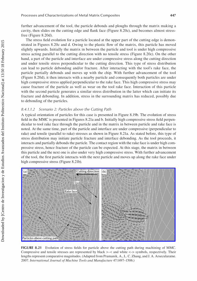
447Processes and Characterizations of Metal Matrix Composites
further advancement of the tool, the particle debonds and ploughs through the matrix making a cavity, then slides on the cutting edge and flank face (Figure 8.20c), and becomes almost stress-free (Figure 8.20d).
The stress field evolution for a particle located at the upper part of the cutting edge is demon-strated in Figures 8.20c and d. Owing to the plastic flow of the matrix, this particle has moved slightly upwards. Initially the matrix in between the particle and tool is under high compressive stress acting parallel to the cutting direction with no tensile stress (Figure 8.20c). On the other hand, a part of the particle and interface are under compressive stress along the cutting direction and under tensile stress perpendicular to the cutting direction. This type of stress distribution can lead to particle debonding and/or fracture. After interacting with the tool’s rake face, the particle partially debonds and moves up with the chip. With further advancement of the tool (Figure 8.20d), it then interacts with a nearby particle and consequently both particles are under high compressive stress applied perpendicular to the rake face. This high compressive stress may cause fracture of the particle as well as wear on the tool rake face. Interaction of this particle with the second particle generates a similar stress distribution in the latter which can initiate its fracture and debonding. In addition, stress in the surrounding matrix has reduced, possibly due to debonding of the particles.
8.4.1.1.2 Scenario 2: Particles above the Cutting PathA typical orientation of particles for this case is presented in Figure 8.19b. The evolution of stress field in the MMC is presented in Figures 8.21a and b. Initially high compressive stress field perpen-dicular to tool rake face through the particle and in the matrix in between particle and rake face is noted. At the same time, part of the particle and interface are under compressive (perpendicular to rake) and tensile (parallel to rake) stresses as shown in Figure 8.21a. As stated before, this type of stress distribution may initiate particle fracture and interface debonding. As the tool proceeds, it interacts and partially debonds the particle. The contact region with the rake face is under high com-pressive stress, hence fracture of the particle can be expected. At this stage, the matrix in between this particle and the next one is also under very high compressive stress. With further advancement of the tool, the first particle interacts with the next particle and moves up along the rake face under high compressive stress (Figure 8.21b).
FIGURE 8.21 Evolution of stress fields for particle above the cutting path during machining of MMC. Compressive and tensile stresses are represented by black >–< and white <–> symbols, respectively. Their lengths represent comparative magnitudes. (Adapted from Pramanik, A., L. C. Zhang, and J. A. Arsecularatne. 2007. International Journal of Machine Tools and Manufacture 47:1497–1506.)
Dow
nloa
ded
by [
Cen
tro
de I
nves
tigac
ion
y de
Est
udio
s A
vanz
ados
del
Ins
titut
o Po
litec
nico
Nac
iona
l] a
t 13:
50 1
8 Fe
brua
ry 2
015

448 Aerospace Materials Handbook
8.4.1.1.3 Scenario 3: Particles below the Cutting PathFigure 8.19c represents this type of tool particle orientation. The stress distribution in the particle and matrix below the cutting edge has a direct influence on the residual stress of the machined sur-face. Figure 8.22a–c show the evolution of stress field for a particle below the cutting edge. As the tool approaches the particle, the matrix in between the cutting edge and particle is under compres-sive stress acting in a radial direction to the cutting edge. However, the particle and particle matrix interface are under compressive and tensile stresses which are acting in a radial direction to the cutting edge and parallel to the cutting edge, respectively (Figure 8.22a). While the tool is passing over the particle, the direction of compressive stress remains radial to the cutting edge. On the other hand, the direction of tensile stresses in the particle becomes parallel to machined surface (Figure 8.22b). At the same time, the magnitudes of both stresses have decreased. It is also noted that the newly generated surface is under compressive residual stress which is parallel to the machined
FIGURE 8.22 Evolution of stress fields for particle below the cutting path during machining of MMC. Compressive and tensile stresses are represented by black >–< and white <–> symbols, respectively. Their lengths represent comparative magnitudes. (Adapted from Pramanik, A., L. C. Zhang, and J. A. Arsecularatne. 2007. International Journal of Machine Tools and Manufacture 47:1497–1506.)
Dow
nloa
ded
by [
Cen
tro
de I
nves
tigac
ion
y de
Est
udio
s A
vanz
ados
del
Ins
titut
o Po
litec
nico
Nac
iona
l] a
t 13:
50 1
8 Fe
brua
ry 2
015

449Processes and Characterizations of Metal Matrix Composites
surface (Figure 8.22c). Similar observations were also reported in an experimental study by Quan and Bangyan (Quan and Ye, 2003), who machined SiC particulate-reinforced MMC.
8.4.1.2 Development of the Plastic ZoneFigures 8.23a–f depict the contours of the von Mises plastic strain in the MMC material at dif-ferent stages of machining. Plastic deformation is observed as the workpiece material enters into the primary deformation zone. The distribution of plastic strain is in layered pattern with a highly strained zone at the tool−chip interface. Plastic strain has clearly increased as the material moves into the chip. However, the particles are well discerned because no plasticity exists in purely elastic particles. Moreover, the deformation patterns are different compared to those of monolithic metal during machining in that the presence of discrete particles causes banded structure and dramati-cally fragments the plastic field.
8.4.1.2.1 Particles along the Cutting PathInitially, for a particle at lower part of the cutting edge, the matrix in between particle and tool, and that at upper part of particle are highly strained (Figure 8.23a). With the progression of cutting, the tool interacts with the particle at cutting edge and the particle is debonded. It then slides and indents (Figures 8.23b and c) into the new workpiece surface causing high plastic strain in the surrounding matrix. As the tool moves further, the particle is released from the matrix leaving a ploughed hole in the surface with high residual strain (Figure 8.23d).
A particle located at the upper part of the cutting edge moves up slightly with the advancement of tool (Figure 8.23c). In this case, the strain in the matrix in between the particle and the tool is not as high as the strain for a particle at lower part of cutting edge discussed earlier. The interaction between the particle and the tool is observed in this case with further progression of tool (Figure 8.23d). Then, the particle partially debonds and slides along the rake face with the chip (Figure 8.23e).
8.4.1.2.2 Particles above the Cutting PathAt first, particles move in the cutting direction with the surrounding matrix due to the movement of the tool. As the rake face of the tool approaches, particle interface becomes highly strained (Figure 8.23b). Due to the ability of the matrix to deform plastically and particle’s inability, the matrix mate-rial experiences very high plastic strain. With further advancement of the tool, particles debond par-tially, interact with the tool and nearby particles, and move with the chip along the rake face (Figures 8.23c–e). At the secondary deformation zone (tool−chip interface), matrix experiences severe defor-mation, hence interfaces of most particles in the chip are highly strained. Additionally, most of the particles debond completely while passing through the secondary deformation zone (Figure 8.23f).
8.4.1.2.3 Particles below the Cutting PathThe interfaces of particles in the workpiece far below the cutting edge do not experience any plastic-ity due to machining. But those situated immediately below the cutting edge are subjected to plastic deformation when the tool passes over them (Figure 8.23e). The banded pattern of the strain field is fragmented in the interface of particles just below the tool cutting edge. With further advancement of the tool, most of the interface of the particle is plastically deformed (Figure 8.23e). Additionally, the matrix at the matrix-tool cutting edge interface is plastically strained. The particles immediately below the cutting edge seem to act like indenters due to their interaction with the tool. In these regions, the matrix can be seen to plastically deform to a greater depth (Figure 8.23f).
8.4.1.3 Cutting Tools and WearPolycrystalline diamond is the most suitable cutting tool material for machining MMCs (Chambers, 1996, Hooper et al., 1999, Heath, 2001), although other cutting tool materials are also used depend-ing on requirements of a specific application. Those are PCBN (Sreejith, 2006), CVD-coated dia-mond (Chou and Liu, 2005), TiCN/TiN-coated (Pedersen and Ramulu, 2006), triple-layered coating
Dow
nloa
ded
by [
Cen
tro
de I
nves
tigac
ion
y de
Est
udio
s A
vanz
ados
del
Ins
titut
o Po
litec
nico
Nac
iona
l] a
t 13:
50 1
8 Fe
brua
ry 2
015

450 Aerospace Materials Handbook
Particle atlower part ofcutting edge Particle debonding
Tool–particleinteractionParticle at upper
part of cutting edge
Particle located at upperpart of cutting edge
Particles releasedfrom chip
Particles remainedin chip
Particle belowcutting path
Plastic strain dueto machining
Original positionof particle
Rough surface due to debondingand ploughing by particle
Debonded particle
Debonding of particlesat secondary shear zone
Ploughing underflank face
Particle at upperpart of cutting edge
Particle abovecutting path
Chipmatrixmaterial
Cutting direction
(a) (b)
(c) (d)
(e) (f )
Rake face
Cutting edgeFlank face
Particle belowcutting path
Workpiece
1.0910.954480.8181260.6817730.595430.4050670.2727130.186360.703E-05
0.442E-05
0.550E-05 0.667E-060.1399450.2798880.4198320.5597760.6997190.8396630.979607
1.121.250
0.1280420.2778590.4167660.5557120.6946390.8335660.973492
1.1121.26
0.367E-050.146990.3537770.4406640.5875510.7344370.881324
1.0281.1751.322
0.1509630.3019220.4528810.603040.7547900.905757
1.0371.2001.359
0.244E-050.1475770.2951510.4427250.5902990.7378730.885447
1.0331.1011.3281.227
FIGURE 8.23 Distribution of von Mises strain during machining of MMC. (Adapted from Pramanik, A., L. C. Zhang, and J. A. Arsecularatne. 2007. International Journal of Machine Tools and Manufacture 47:1497–1506.)
Dow
nloa
ded
by [
Cen
tro
de I
nves
tigac
ion
y de
Est
udio
s A
vanz
ados
del
Ins
titut
o Po
litec
nico
Nac
iona
l] a
t 13:
50 1
8 Fe
brua
ry 2
015

451Processes and Characterizations of Metal Matrix Composites
of TiC/Al2O3/TiCN (Ciftci et al., 2004) and carbide (Karthikeyan et al., 2001, Kilickap et al., 2005, Pedersen and Ramulu, 2006, Varadarajan et al., 2006). Regardless of the type of cutting tool materi-als, comparatively high tool wear and worse surface finish are always associated with the machining of MMCs in comparison with the cutting of the corresponding matrix materials. This is due to the tool−particle interactions which are affected by cutting conditions, size, and volume percentage of reinforcements. Information on tool performance is available mainly for aluminum alloy and simi-lar metals such as magnesium matrix MMCs (Pedersen and Ramulu, 2006).
Wear mechanism such as abrasion, adhesion, microcracking, and fatigue have been used to explain tool wear during machining of MMCs (Arsecularatne et al., 2006). Due to the presence of hard-reinforced particles and debonded tool material grains, two- and three-body abrasions take place during machining of an MMC (Weinert, 1993, Chambers, 1996, Hooper et al., 1999, Quan and Zehua, 2000, Heath, 2001, Davim, 2002, Ding et al., 2005). These cause tool pitting, chipping, microcracking, and fatigue (El-Gallab and Sklad, 2000, D’Errico and Calzavarini, 2001). Adhesion is also a cause of tool wear in addition to abrasion, as thin films of workpiece materials were found on the worn areas. The abrasion is associated with micromechanical damage rather than microcut-ting (Hooper et al., 1999, Andrewes et al., 2000).
Chemical wear during machining of MMCs has not been reported. This is because the con-stituents of an MMC, that is, matrix material and reinforced particles (e.g., SiC and Al2O3) are chemically inert to almost all cutting tools (e.g., PCD, CVD-coated, carbide tools) under almost any conditions. Thus, tool wear is reasonably dependent on hardness of tool material. At simi-lar cutting conditions, harder cutting tools exhibit longer tool life than softer tools. For coated/uncoated tungsten carbide tools, when machining MMCs, tool wear is due to mechanical abrasion (Arsecularatne et al., 2006). The increased thickness of diamond CVD coating increases the per-formance of the tool and the thick (500 µm) CVD diamond coating may be considered a competitor to PCD (Andrewes et al., 2000, D’Errico and Calzavarini, 2001). Bonding between the substrate and the coating is critical to this tool performance. Coating failure is the dominant wear mecha-nism for diamond CVD-coated tools during the machining of MMCs. Coating failure accelerates at high temperature due to different thermal expansions between the coating and the substrate (Chou and Liu, 2005). Polycrystalline diamond tools with zero rake angle and large tool nose radii were recommended for roughing operations (El-Gallab and Sklad, 1998a). Incorporation of ultrasonic vibration reduces surface tearing, plastic deformation, and built-up-edge during machining and provides a more stable cutting process (Zhao et al., 2002). The increase of reinforcement content increased the hardness of MMCs, and hence increases the flank wear of the tool and roughness of MMC workpiece machined (Figure 8.24). However, cutting at cryogenic temperature reduces the chip length, flank wear, and roughness (Lin et al., 2001).
0
0.1
0.2
0.3
Flan
k w
ear:
VB (m
m)
0.4
0.5
0.60.7
050 100
Cutting time (min)
20 vol%SiC10 vol%SiC, 4 vol%Ni-Gr6 vol%SiC, 2.5 vol%Ni-Gr5 vol%SiC, 4 vol%Ni-GNon reinforced alloy
150 200 250
FIGURE 8.24 Effect of reinforcement content (in Al-380 matrix) on the flank wear of a TiCN-coated car-bide insert at 60 m/min cutting speeds. (Adapted from Songmene, V. and M. Balazinsk. 1999. Annals of the CIRP 48(1):77–80.)
Dow
nloa
ded
by [
Cen
tro
de I
nves
tigac
ion
y de
Est
udio
s A
vanz
ados
del
Ins
titut
o Po
litec
nico
Nac
iona
l] a
t 13:
50 1
8 Fe
brua
ry 2
015

452 Aerospace Materials Handbook
High speed and low feed accelerated tool wear for a PCD tool (Davim, 2002). Surface rough-ness improves with an increase in the feed rate and the cutting speed, but slightly deteriorates with an increase in the depth of cut. This is due to the reduction in the flank wear of the tool with an increase in feed rate (El-Gallab and Sklad, 1998b). The rate of tool wear is higher at high cutting speeds (700 m/min) and low feeds (0.05 mm/rev) (Davim and Baptista, 2000, Ding et al., 2005). The volume fraction and the size of SiC particle are most influential factors on tool wear. MMCs reinforced by coarse SiC particles cause higher tool wear (Quan and Zehua, 2000). Figure 8.25 compares the tool life of different tool materials at different cutting speeds. According to this fig-ure, tool materials can be ranked (i.e., high-speed steel, titanium nitride-coated high-speed steel, tungsten carbide, PCBN, and PCD) based on the tool life (lower to higher) during machining MMCs (Hung et al., 1996).
The cast MMCs exhibit higher machinability than that of the powder-formed MMCs mainly because of the favorable shape and distribution of the particles (Hung et al., 1995, 1996). Carbide tools for roughing operations, and cubic boron nitride and polycrystalline diamond tools for fin-ish-machining are generally recommended. The latter tools have acceptable tool lives, and cause minimum damage to the subsurface. The hard aluminum matrix as a result of heat treatment signifi-cantly shortens the tool life. The fractured and debonded particles along or underneath a machined surface (Figure 8.26) could be of concern when composites are used in critical applications (Hung et al., 1996).
8.4.2 Milling
The hard reinforcement particles generally cause higher tool wear during milling of MMCs too. Polycrystalline diamond, carbide, and coated (TiAlN, TiN+ TiAlN, TiCN+ Al2O3+ TiN) carbide tools have been reported to mill MMCs (Karakaş et al., 2006, Übeyli et al., 2007, 2008, Reddy et al., 2008). Tool wear reduces when harder tool materials are used. Enhanced machinability of
10010–3
10–2
10–1
Circ
umfe
renc
e spe
ed (m
/s) 100
101
101 102 103
Tool life (s)
20%SiCp/HSS10%SiCp/HSS20%SiCp/TiN-HSS20%SiCp/CARBIDE K1010%SiCp/CARBIDE K1020%SiCp/CBN(estimated)20%SiCp/DIAMOND(estimated)
104 105
FIGURE 8.25 Tool life of different tool materials during the turning of Al–Li/SiCp composite with a 0.5 mm depth of cut and 0.07 mm/rev feed for different peripheral speeds. (Adapted from Hung, N. P. et al. 1996. Journal of Materials Processing Technology 56:966–977.)
Dow
nloa
ded
by [
Cen
tro
de I
nves
tigac
ion
y de
Est
udio
s A
vanz
ados
del
Ins
titut
o Po
litec
nico
Nac
iona
l] a
t 13:
50 1
8 Fe
brua
ry 2
015

453Processes and Characterizations of Metal Matrix Composites
MMCs is noted compared to a nonreinforced matrix alloy during milling (Reddy et al., 2008). Though the tendency to clog the cutting tool is very low, workpiece material adhesion appears a little distance away from the tool tip along the rake and clearance face on the tool tip (Reddy et al., 2008). Under similar machining conditions, MMCs (Al/SiC) give better surface finish than that of matrix materials. Machined surface roughness and forces increase with the increase of feed. Surface roughness decreases with the increase of cutting speed. Compressive residual stresses are generated in the surface of milled MMCs. It is seen that tool wear increases almost linearly with the increase of chip volume. At a low speed, feed does not influence flank wear significantly but at higher speeds flank wear decreases with the increase of feed (Übeyli et al., 2007).
Abrasion and adhesion are the main wear mechanisms for all of the tools mentioned above. Similar to the turning operation, BUE formation is observed at low cutting speeds but its extent decreases with the increase of the speed. During the milling of MMCs, coated carbide tools per-form better than uncoated ones at all cutting speeds and feed rates tested. Performance of carbide milling tools increases with the increase of coating layer and thickness. Tool wear increases with the increase of cutting speeds and decreases with the increase of feed. Generally, low cutting speeds and high feed rates are desirable to reduce tool wear during milling aluminum MMCs (Karakaş et al., 2006, Übeyli et al., 2007, 2008).
FIGURE 8.26 SEM images of the machined surface at a cutting speed of 670 m/min, a depth of cut of 1.5 mm and a feed rate of 0.45 mm/rev, for 1.6 mm nose radius and 0° rake angle: (a) typical topography; (b) voids around the SiC particles; (c) pulled-out SiC particles; and (d) fracture or crushed SiC particles. (Adapted from El-Gallab, M. and M. Sklad. 1998b. Journal of Materials Processing Technology 83:277–285.)
Dow
nloa
ded
by [
Cen
tro
de I
nves
tigac
ion
y de
Est
udio
s A
vanz
ados
del
Ins
titut
o Po
litec
nico
Nac
iona
l] a
t 13:
50 1
8 Fe
brua
ry 2
015

454 Aerospace Materials Handbook
8.4.3 grinding
The grinding of MMCs, however, has received little attention in research. Therefore, information on grinding of MMCs is very much limited. Because of the tendency of the chip loading to wheels, the grinding process does not perform very well on soft materials (Ilio et al., 1996). Grinding of MMCs can be done reasonably well, due to the improved chip breakability of MMCs (Ilio et al., 1996, Pramanik et al., 2008b). The grindability of MMC is better compared to that of a nonreinforced aluminum alloy in terms of a better surface finish and a lower tendency of chip loading to wheel (Ilio et al., 1996). Different types of grinding wheel materials, such as silicon carbide, alumina, CBN, diamond (resin bonded and electroplated), and so on, have been tested on MMCs (Ilio et al., 1996, Chang et al., 1999, Zhong and Hung, 2002, Ronald et al., 2009). These influence the specific energy of the grinding process. Specific energy, which is defined as the ratio of the grinding power to material removal rate, is a performance indicator of a grinding process. Hung et al. (Hung et al., 1997) calcu-lated the specific energy in the grinding of 10% and 20% SiC-reinforced 359 Al using diamond and CBN wheels. They found that specific grinding energy is higher when using fine abrasives, and that the energy increases with increasing the reinforcement content. Super abrasive wheels of appropriate grit and binder are often desirable, because chip loading and attrition wear would be lower (Ronald et al., 2009). Generally, lamella-structured curled chips are generated during the grinding of MMCs with 15, 20, or 25 vol% particulate and 20 vol% whisker-reinforced aluminum (Al 2009) (Ilio et al., 1996).
Grinding wheels bonded by hard bonding, such as electroplated wheels, experience a relatively higher grinding force, acoustic emission energy, and surface roughness compared to that with softer bond materials (e.g., resin) (Ronald et al., 2009). Figure 8.27 presents the variation of surface rough-ness during the grinding of different types of MMCs by different types of grinding wheels at dif-ferent speeds. Grinding wheel degrades quickly when used for MMCs with higher percentage of reinforcement. The grinding forces show an increasing trend with the wheel degradation and hard-ness (Zhong, 2003), and with the increase of depth of cut (Ilio et al., 1996, Kwak and Kim, 2008). Volume fraction and properties, such as hardness, of the reinforcement as well as the shape and dimension, play an important role in both surface texture and tool wear (Ilio et al., 1996). Smearing of the aluminum matrix on the ground surfaces has been noted during rough grinding, but it reduces during fine grinding (Zhong, 2003, Hung et al., 1999, Zhong and Hung, 2000).
Grinding imposes compressive stresses on the machined surface and creates a macroscopic compressive zone in the near surface region. As the depth increases across the machined surface,
0.01100 1650
Grinding speed (m min–1)2200
0.1
0.2
0.3
0.4
0.5
0.6
0.72618/Al2O3/10p-Fine2618/Al2O3/20p-Fine2618/Al2O3/10p-Rough2618/Al2O3/20p-Rough
Ra (μ
m)
FIGURE 8.27 Surface roughness of ground 2618Al/10%Al2O3p and 2618Al/20%Al2O3p. Rough grinding (80-grit SiC wheel; depth of cut: 15 µm; cross-feed: 3 mm). Fine grinding (3000-grit diamond wheel; depth of cut: 1 µm; cross-feed: 1 mm). (Adapted from Zhong, Z. W. 2003. International Journal of Advanced Manufacturing Technology 21:79–83.)
Dow
nloa
ded
by [
Cen
tro
de I
nves
tigac
ion
y de
Est
udio
s A
vanz
ados
del
Ins
titut
o Po
litec
nico
Nac
iona
l] a
t 13:
50 1
8 Fe
brua
ry 2
015

455Processes and Characterizations of Metal Matrix Composites
the effect of grinding diminishes, and the residual stresses gradually return to the original levels (Lee et al., 1995). Work hardening of matrix material is generally limited to the depth equal to the diameter of reinforcements approximately (Hung et al., 1997). Diamond wheels generate lower forces and surface cracks compared to other abrasive materials. Presence of reinforced particles arrests the spread of the cracks (Chang et al., 1999). SiC wheels can be used for rough grinding of alumina/aluminum composites, because SiC is harder than Al2O3 and much less expensive than diamond (Zhong and Hung, 2002, Zhong, 2003). Rough grinding with a SiC wheel followed by fine grinding with a fine-grit diamond wheel is recommended for the grinding of alumina/alumi-num composites.
REFERENCES
Andrewes, C. J. E., H. Y. Feng, and W. M. Lau. 2000. Machining of an aluminum/SiC composite using diamond inserts. Journal of Materials Processing Technology 102:25–29.
Arsecularatne, J. A., L. C. Zhang, and C. Montross. 2006. Wear and tool life of tungsten carbide, PCBN and PCD cutting tools. International Journal of Machine Tools & Manufacture 46:482–491.
Arsenault, R. J., L. Wang, and C. R. Feng. 1991. Strengthening of composites due to microstructural changes in the matrix. Acta Metallurgica et Materialia 39:47–57.
Assar, A. E. M. 1999. Fabrication of metal matrix composite by infiltration process—Part 2: Experimental study. Journal of Materials Processing Technology 86:152–158.
Barmouz, M., P. Asadia, M. K. BesharatiGivi, and M. Taherishargh. 2010. Investigation of mechanical proper-ties of Cu/SiC composite fabricated by FSP: Effect of SiC particles’ size and volume fraction. Materials Science and Engineering A 528:1740–1749.
Blucher, J. T., U. Narusawa, M. Katsumata, and A. Nemeth. 2001. Continuous manufacturing of fiber-reinforced metal matrix composite wires—Technology and product characteristics. Composites Part A 32:1759–1766.
Brendel, A., V. Paffenholz, T. Köck, and H. Bolt. 2009. Mechanical properties of SiC long fibre reinforced cop-per. Journal of Nuclear Materials 386–388:837–840.
Caceres, C. H. and W. J. Poole. 2002. Hardness and flow strength in particulate metal matrix composites. Materials Science and Engineering A 332:311–317.
Chambers, A. R. 1996. The machinability of light alloy MMCs. Composites: Part A 27:143–147.Chandra, N. and H. Ghonem. 2001. Interfacial mechanics of push-out tests: Theory and experiments.
Composites: Part A 32:575–584.Chang, S. T., W. H. Tuan, H. C. You, and I. C. Lin. 1999. Effect of surface grinding on the strength of NiAl and
Al2O3/NiAl composites. Materials Chemistry and Physics 59:220–224.Chen, J., C. Hao, and J. Zhang. 2006. Fabrication of 3D-SiC network reinforced aluminum–matrix composites
by pressureless infiltration. Materials Letters 60:2489–2492.Choi, Y., M. E. Mullins, K. Wijayatilleke, and J. K. Lee. 1992. Fabrication of metal matrix composites of
TiC-Al through self-propagating synthesis reaction. Metallurgical and Materials Transactions 23A: 2387–2392.
Chou, Y. K., and J. Liu. 2005. CVD diamond tool performance in metal matrix composite machining. Surface & Coatings Technology 200:1872–1878.
Ciftci, I., M. Turker, and S. Ulvi. 2004. Evaluation of tool wear when machining SiCp reinforced Al-2014 alloy matrix composites. Materials and Design 25:251–255.
Davim, J. P. 2002. Diamond tool performance in machining metal–matrix composites. Journal of Materials Processing Technology 128:100–105
Davim, J. P. and A. M. Baptista. 2000. Relationship between cutting force and PCD cutting tool wear in machin-ing silicon carbide reinforced aluminium. Journal of Materials Processing Technology 103:417–423.
Degischer, H. P., P. Prader, and C. S. Marchi. 2001. Assessment of metal matrix composites for innova-tions-intermediate report of a European thematic network. Composites Part A: Applied Science and Manufacturing 32(8):1161–1166.
D’Errico, G. E. and R. Calzavarini. 2001. Turning of metal matrix composites. Journal of Materials Processing Technology 119:257–260.
Diehl, W. and S. Detlev. 1990. Injection moulding of superalloys and intermetallic phases. Metal Powder Report 45:333–334, 336–338.
Ding, X., W. Y. H. Liew, and X. D. Liu. 2005. Evaluation of machining performance of MMC with PCBN and PCD tools. Wear 259:1225–1234.
Dow
nloa
ded
by [
Cen
tro
de I
nves
tigac
ion
y de
Est
udio
s A
vanz
ados
del
Ins
titut
o Po
litec
nico
Nac
iona
l] a
t 13:
50 1
8 Fe
brua
ry 2
015

456 Aerospace Materials Handbook
Doel, T. J. A. and P. Bowen. 1996. Effect of particle size and matrix aging condition on toughness of particle reinforced aluminium based metal matrix composites. Materials Science and Technology 12:586–594.
El-Gallab, M. and M. Sklad. 1998a. Machining of Al:SiC particulate metal matrix composites. Part I: Tool performance. Journal of Materials Processing Technology 83:151–158.
El-Gallab, M. and M. Sklad. 1998b. Machining of Al/SiC particulate metal matrix composites Part II: Workpiece surface integrity. Journal of Materials Processing Technology 83:277–285.
El-Gallab, M. and M. Sklad. 2000. Machining of Al/SiC particulate metal matrix composites Part III: Comprehensive tool wear models comprehensive tool wear models. Journal of Materials Processing Technology 101:10–20.
Fei, W. D., M. Hu, and C. K. Yao. 2003. Effects of thermal residual stress creeping on microstructure and tensile properties of SiC whisker reinforced aluminum matrix composite. Materials Science and Engineering A 356:17–22.
Fiori, F., E. Girardin, A. Giuliani, T. Lorentzen, A. Pyzalla, F. Rustichelli, and V. Stanic. 2000. Neutron diffraction measurements for the determination of residual stresses in MMC tensile and fatigue speci-mens. Physica B 276–278:923–924.
Flom, Y. and R. J. Arsenault. 1989. Effect of particle size on fracture toughness of SiC/Al composite material. Acta Metall 37:2413–23.
García-Leiva, M. C., I. Ocaña, A. Martín-Meizoso, J. M. Martínez-Esnaola, V. Marqués, and F. Heredero. 2003. High temperature tensile and fatigue behaviour of the unidirectionally reinforced MMC Ti64/SiC. Engineering Fracture Mechanics 70:2137–2148.
Gariboldi, E., and C. Santulli, F. Stivali, and M. Vedani. 1996. Evaluation of tensile damage in particulate-reinforced MMC’s by acoustic emission. Scripta Materialia 35:273–277.
German, R. M. and A. Bose. 1989. Fabrication of intermetallic matrix composites. Materials Science and Engineering A 107:107–112.
Gooder, J. L. and S. Mall. 1995. Compressive behavior of a titanium metal matrix composite with a circular hole. Composite Structures 31:315–324.
Gotman, I., M. J. Koczak, and E. Shtessel. 1994. Fabrication of Al matrix in-situ composites via self-propagating synthesis. Materials Science and Engineering A 187:189–199.
Hanabe, M. R. and P. B. Aswath. 1996. Al2O3/Al particle-reinforced aluminum matrix composite by displacement reaction. Journal of Materials Research 11:1562–1569.
Hanabe, M. and P. B. Aswath. 1997. Synthesis of in-situ reinforced Al composites from Al-Si-Mg-O precursors. Acta Materialia 45:4067–4076.
Harris, S. J., K. Dinsdale, Y. Gao, and B. Noble. 1988. Mechanical and physical behaviour of metallic and ceramic composites. In: Proc. 9th Risø Int. Sym. (eds. S.I. Andersen, H. Lilholt, O. B. Pederson) (Risø Press, Denmark): 373.
Hashim, J., L. Looney, and M. S. J. Hashmi. 2001. The enhancement of wettability of SiC particles in cast aluminium matrix composites. Journal of Materials Processing Technology 119:329–335.
Heath, P. J. 2001. Developments in the applications of PCD tooling. Journal of Materials Processing Technology 116:31–38.
Hong, S. Y. Y. Ding, and R. G. Ekkens. 1999. Improving low carbon steel chip breakability by cryogenic chip cooling. International Journal of Machine Tools & Manufacture 39:1065–1085.
Hooper, R. M., J. L. Henshall, and A. Klopfer. 1999. The wear of polycrystalline diamond tools used in the cutting of metal matrix composites. International Journal of Refractory Metals and Hard Materials 17:103–109.
Hu, M., W. D. Fei, and C. K. Yao. 2002. Effect of heat treatment on dislocation states and work hardening behaviors of SiCw/6061Al composite. Materials Letters 56:637–641.
Huda, D., M. A. El-Baradie, and M. S. J. Hashmi. 1994. Analytical study for the stress analysis of metal matrix composites. Journal of Materials Processing Technology 45:429–434.
Humphreys, F. J. 1991. The thermomechanical processing of A1-SiC particulate composites. Materials Science and Engineering A 135:267–273.
Hung, N. P., F. Y. C. Boey, K. A. Khor, C. A. Oh, and H. F. Lee. 1995. Machinability of cast and powder-formed aluminum alloys reinforced with SiC particles. Journal of Materials Processing Technology 48:291–297.
Hung, N. P., F. Y. C. Boey, K. A. Khor, Y. S. Phua, and H. F. Lee. 1996. Machinability of aluminum alloys reinforced with silicon carbide particulates. Journal of Materials Processing Technology 56:966–977.
Hung, N. P., N. L. Loh, and V. C. Venkatesh. 1999. Machining of metal matrix composites. In: Machining of Ceramics and Composites. (eds. S. Jahanmir, M. Ramulu and P. Koshy) (Marcel Dekker, Inc., Basel, New York).
Dow
nloa
ded
by [
Cen
tro
de I
nves
tigac
ion
y de
Est
udio
s A
vanz
ados
del
Ins
titut
o Po
litec
nico
Nac
iona
l] a
t 13:
50 1
8 Fe
brua
ry 2
015

457Processes and Characterizations of Metal Matrix Composites
Hung, N. P., S. H. Yeo, K. K. Lee, and K. J. Ng. 1998. Chip formation in machining particle-reinforced metal matrix composites. Materials and Manufacturing Processes 13(1):85–100.
Hung, N. P., Z. W. Zhong, and C. H. Zhong. 1997. Grinding of metal matrix composites reinforced with silicon-carbide particles. Materials and Manufacturing Processes 12(6):1075–1091.
Ilio, A. D., A. Paoletti, V. Tagliaferri, and F. Veniali. 1996. An experimental study on grinding of silicon carbide reinforced aluminium alloys. International Journal of Machine Tools and Manufacture 36:673–685.
Jawahir, I. S. 1990. On the controllability of chip breaking cycles and modes of chip breaking in metal machin-ing. Annals of the CIRP 39(1):47–51.
Jiang, J. and B. Dodd. 1995. Workability of aluminium-based metal matrix composites in cold compression. Composites 26:62–66.
Joshi, S. S., N. Ramakrishnan, and P. Ramakrishnan. 2001. Micro-structural analysis of chip formation dur-ing orthogonal machining of Al/SiCp composites. Journal of Engineering Materials and Technology 123:315–321.
Karthikeyan, R., G. Ganesan, R. S. Nagarazan, and B. C. Pai. 2001. A critical study on machining of Al/SiC composites. Materials and Manufacturing Processes 16(1):47–60.
Karakaş, M. S., A. Acir, M. Übeyli, and B. Ögel. 2006. Effect of cutting speed on tool performance in milling of B4Cp reinforced aluminum metal matrix composites. Journal of Materials Processing Technology 178:241–246.
Kellie, J. and J. V. Wood. 1995. Reaction processing in the metals industry. Materials World 3:10–12.Kilickap, E., O. Cakir, M. Aksoy, and A. Inan. 2005. Study of tool wear and surface roughness in machining
of homogenised SiC-p reinforced aluminium metal matrix composite. Journal of Materials Processing Technology 164–165:862–867.
Kolednik, O. and K. Unterweger. 2008. The ductility of metal matrix composites- relation to local deformation behavior and damage evolution. Engineering Fracture Mechanics 75:3663–3676.
Kuruvilla, A. K., K. S. Prasad, V. V. Bhanuprasad, and Y. R. Mahajan. 1990. Microstructure−property correla-tion in Al TiB2 (XD) composites. Scripta Metallurgica et Materiala 24:873–878.
Kwak, J. S. and Y. S. Kim, 2008. Mechanical properties and grinding performance on aluminum-based metal matrix composites. Journal of Materials Processing Technology 201:596–600.
Lee, R. S., G. A. Chen, and B. H. Hwang. 1995. Thermal and grinding induced residual stresses in a silicon carbide particle-reinforced aluminium metal matrix composite. Composites 26:425–429.
Lee, A.K., L.E. Sanchez-Caldera, S.T. Oktay, and N.P. Suh. 1992. Liquid-metal mixing process tailors MMC microstructures. Advanced Materials & Processes 8:31–34.
Lee, H. S., J. S. Yeo, S. H. Hong, D. J. Yoon, and K. H. Na. 2001. The fabrication process and mechanical prop-erties of SiCp/Al–Si metal matrix composites for automobile air-conditioner compressor pistons. Journal of Materials Processing Technology 113:202–208.
Leggoe, J. W. 2004. Determination of the elastic modulus of microscale ceramic particles via nanoindentation. Journal of Materials Research 19(8):2437–2447.
Leggoe, J. W., X. Z. Hu, M. V. Swain, and M. B. Bush. 1994. An ultra-micro indentation investigation of aspects of the fracture process in particulate reinforced metal matrix composites. Scripta Metallurgica et Materialia 31(5):577–582.
Leng, J., G. Wu, Q. Zhou, Z. Dou, and X. L. Huang. 2008. Mechanical properties of SiC/Gr/Al composites fabricated by squeeze casting technology. Scripta Materialia 59:619–622.
Leucht, R. and H. J. Dudek. 1994. Properties of SiC fibre reinforced titanium alloys processed by fibre coating and hot isostatic pressing. Materials Science and Engineering A 188:201–210.
Lin, J. T., D. Bhattacharyya, and W. G. Ferguson. 1998. Chip formation in the machining of SiC particle rein-forced aluminium matrix composites. Composites Science and Technology 58:285–291.
Lin, J. T., D. Bhattacharyya, and C. Lane. 1995. Case study machinability of a silicon carbide reinforced alu-minium metal matrix composite. Wear 181–183:883–888.
Lin, C. B., Y. W. Hung, W. C. Liu, and S. W. Kang. 2001. Machining and fluidity of 356Al/SiC(p) composites. Journal of Materials Processing Technology 110:152–159.
Lin, Y., R.H. Zee, and B.A. Chin. 1991. In situ formation of three-dimensional TiC reinforcements in Ti-TiC composites. Metallurgical Transactions A 22:859–865.
Loh, N. H., S. B. Tor, and K. A. Khor. 2001. Production of metal matrix composite part by powder injection molding. Journal of Materials Processing Technology 108:398–407.
Ma, Z. Y., J. H. Li, S. X. Li, X. G. Ning, Y. X. Lu, and J. Bi. 1996. Property-microstructure correlation in-situ formed Al2O3, TiB2 and Al3Ti mixture-reinforced aluminium composites. Journal of Materials Science 31(3): 741–747.
Dow
nloa
ded
by [
Cen
tro
de I
nves
tigac
ion
y de
Est
udio
s A
vanz
ados
del
Ins
titut
o Po
litec
nico
Nac
iona
l] a
t 13:
50 1
8 Fe
brua
ry 2
015

458 Aerospace Materials Handbook
Ma, Z. Y. and S.C. Tjong. 1997. In situ ceramic particle-reinforced aluminum matrix composites fabricated by reaction pressing in the TiO2 (Ti)-Al-B (B2O3) systems. Metallurgical and Materials Transactions 28A(9): 1931–1942.
Maity, P. C., S. C. Panigrahi, and P. N. Chakraborty. 1993. Preparation of aluminium-alumina in-situ particle composite by addition of titania to aluminium melt. Scripta Metallurgica et Materialia 28:549–552.
McClintock, F. A. and A. S. Argon. 1966. Mechanical Behavior of Materials. (Addison-Wesley Publishing Company Inc, Massachusetts, USA).
McDaniels, D. L. 1985. Analysis of stress–strain, fracture, and ductility behavior of aluminium matrix compos-ites containing discontinuous silicon carbide reinforcements. Metallurgica Transactions 16A:1105–1115.
McLean, A., H. Soda, Q. Xia, A. K. Pramanick, A. Ohno, G. Motoyasu, T. Shimizu, S. A. Gedeon, and T. North. 1997. SiC particulate-reinforced, aluminium-matrix composite rods and wires produced by a new con-tinuous casting route. Composites Part A 28A:153–162.
Miracle, D. B. 2005. Metal matrix composites—From science to technological significance. Composites Science and Technology 65:2526–2540.
Mortensen, A. and J. A. Cornie. 1991. On the infiltration of metal matrix composites. Metallurgical and Materials Transactions A 22:1160–1163.
Mussert, K. M., W. P. Vellinga, A. Bakker, and S. V. D. Zwaag. 2002. A nano-indentation study on the mechanical behaviour of the matrix material in an AA6061-Al2O3 MMC. Journal of Materials Science 37(4):789–794.
Ng, E. and D. K. Aspinwall. 2002. The effect of workpiece hardness and cutting speed on the machinability of AISI H13 hot work die steel when using PCBN tooling. Transaction of the ASME 124:588–594.
Oñoro, J., M. D. Salvadorb, and L. E. G. Cambroneroc. 2009. High-temperature mechanical properties of alu-minium alloys reinforced with boron carbide particles. Materials Science and Engineering A 499:421–426.
Oxley, P. L. B. 1962. Shear angle solutions in orthogonal machining. International Journal of Machine Tool Design and Research 2(3):219–229.
Ozben, T., E. Kilickap, and O. Çakır. 2008. Investigation of mechanical and machinability properties of SiC particle reinforced Al-MMC. Journal of Materials Processing Technology 198:220–225.
Ozcatalbas, Y. 2003a. Investigation of the machinability behaviour of Al4C3 reinforced Al-based composite produced by mechanical alloying technique. Composites Science and Technology 63(1):53–61.
Ozcatalbas, Y. 2003b. Chip and built-up edge formation in the machining of in situ Al4C3–Al composite. Materials & Design 24(3):215–221.
Pandey, A. B., B. S. Majumdar, and D. B. Miracle. 2000. Deformation and fracture of a particle-reinforced aluminum alloy composites: Part I. Experiments. Metallurgical Transactions 31A:921–936.
Partridge, P. G. and C. M. Ward-Close. 1993. Processing of advanced continuous fibre composites: Current practice and potential developments. International Materials Reviews 38:1–24.
Pedersen, W. and M. Ramulu. 2006. Facing SiCp/Mg metal matrix composites with carbide tools. Journal of Materials Processing Technology 172:417–423.
Pelleg, J., S. Sofer, M. Alkoby, and M. Ganor. 1995. In-situ formation of the Ti3A1-SiC metal matrix composite system from its components. Materials Science and Engineering A 203:305–313.
Peng, J., D. H. W. Li, J. D. Y. Xie, and G. Liu. 2008. Study on the yield behavior of Al2O3–SiO2(sf)/Al–Si metal matrix composites. Materials Science and Engineering A 486:427–432.
Pereyra, R. and Y. L. Shen. 2004. Characterization of particle concentration in indentation-deformed metal-ceramic composites. Material Characterization 53:373–380.
Pereyra, R. and Y. L. Shen. 2005. Characterization of indentation-induced “particle crowding” in metal matrix composites. International Journal of Damage Mechanics 14(3):197–213.
Pramanik, A. and L. C. Zhang. 2009. Machining metal matrix composites (Chapter 5). In: Machining Composite Materials. (ed. J. P. Davim) (John Wiley & Sons, United Kingdom) (ISBN: 9781848211704).
Pramanik, A., L. C. Zhang, and J. A. Arsecularatne. 2007. An FEM investigation into the behaviour of metal matrix composites: Tool−particle interaction during orthogonal cutting. International Journal of Machine Tools and Manufacture 47:1497–1506.
Pramanik, A., L. C. Zhang, and J. A. Arsecularatne. 2008a. Deformation mechanisms of MMCs under indenta-tion. Composites Science and Technology 68:1304–1312.
Pramanik, A., L. C. Zhang, and J. A. Arsecularatne. 2008b. Machining of metal matrix composites: Effect of ceramic particles on residual stress, surface roughness and chip formation. International Journal of Machine Tools & Manufacture 48:1613–1625.
Prasad, V. V. B., B. V. R. Bhat, Y. R. Mahajan, and P. Ramakrishnan. 2002. Structure-property correlation in discontinuously reinforced aluminium matrix composites as a function of relative particle size ratio. Materials Science and Engineering A 337:179–186.
Dow
nloa
ded
by [
Cen
tro
de I
nves
tigac
ion
y de
Est
udio
s A
vanz
ados
del
Ins
titut
o Po
litec
nico
Nac
iona
l] a
t 13:
50 1
8 Fe
brua
ry 2
015

459Processes and Characterizations of Metal Matrix Composites
Quan, Y. and Z. Zehua. 2000. Tool wear and its mechanism for cutting SiC particle reinforced aluminium matrix composites. Journal of Materials Processing Technology 100(1):194–199.
Quan, Y. M., Z. H. Zhou, and B. Y. Ye. 1999. Cutting process and chip appearance of aluminum matrix composites reinforced by SiC particle. Journal of Materials Processing Technology 91(1):231–235.
Quan, Y. and B. Ye. 2003. The effect of machining on the surface properties of SiC/Al composites. Journal of Materials Processing Technology 138(1–3):464–467.
Rashad, R. M. and T. M. El-Hossainy. 2006. Machinability of 7116 structural aluminum alloy. Materials and Manufacturing Processes 21:23–27.
Ralph, B., H. C. Yuen, and W. B. Lee. 1997. The processing of metal matrix composites—An overview. Journal of Materials Processing Technology 63:339–353.
Ranganath, S., M. Vijayakumar, and J. Subrahmanyam. 1992. Combustion-assisted synthesis of TiTiBTiC composite via the casting route. Materials Science and Engineering A 149:253–257.
Reddy, N. S. K., S. Kwang-sup, and M. Yang. 2008. Experimental study of surface integrity during end milling of Al/SiC particulate metal–matrix composites. Journal of Materials Processing Technology 201:574–579.
Robertson, D. D. and S. M. Mall. 1994. Micromechanical analysis for thermoviscoplastic behavior of unidirec-tional fibrous composites. Composites Science and Technology 50:483–496.
Ronald, B. A., L. Vijayaraghavan, and R. Krishnamurthy 2009. Studies on the influence of grinding wheel bond material on the grindability of metal matrix composites. Materials and Design 30:679–686.
Sahoo, P. and M. J. Koczak. 1991a. Analysis of in situ formation of titanium carbide in aluminum alloys. Materials Science and Engineering A 144:37–44.
Sahoo, P. and M. J. Koczak. 1991b. Microstructure−property relationships of in situ reacted TiC/AlCu metal matrix composites. Materials Science and Engineering A 131:69–76.
Sharma, S. R., Z. Y. Ma, and R.S. Mishra. 2004. Effect of friction stir processing on fatigue behavior of A356 alloy. Scripta Materialia 51:237–241.
Shen, Y. L. and N. Chawla. 2001b. On the correlation between hardness and tensile strength in particle rein-forced metal matrix composites. Materials Science and Engineering A 297(1–2):44–47.
Shen, Y. L., E. Fishencord, and N. Chawla. 2000. Correlating macrohardness and tensile behavior in discon-tinuously reinforced metal matrix composites. Scripta Materialia 42(5):427–432.
Shen, Y. L., J. J. Williams, G. Piotrowski, N. Chawla, and Y. L. Guo. 2001a. Correlation between tensile and indentation behavior of particle-reinforced metal matrix composites: An experimental and numerical study. Acta Materialia 49:321–3229.
Shi, N. and R. J. Arsenault. 1991. Analytical evaluation of the thermal residual stresses in Si/Al composites. JSME International Journal 34(2):143–155.
Slipenyuk, A., V. Kuprin, Y. Milman, J. E. Spowart, and D. B. Miracle. 2004. The effect of matrix to rein-forcement particle size ratio (PSR) on the microstructure and mechanical properties of a P/M processed AlCuMn/SiCp MMC. Materials Science and Engineering A 381:165–170.
Songmene, V. and M. Balazinsk. 1999. Machinability of graphitic metal matrix composites as a function of reinforcing particles. Annals of the CIRP 48(1):77–80.
Sreejith, P. S. 2006. Tool wear of binderless PCBN tool during machining of particulate reinforced MMC. Tribology Letters 22(3):265–269.
Stephens J. J., J. P. Lucas, and F. M. Hosking. 1988. Cast Al–7Si composites: effect of particle type and size on mechanical properties. Scripta Materialia 22:1307–1312.
Subramanian, P. R., S. Krishnamurthy, S. T. Keller, and M. G. Mendiratta. 1998. Processing of continuously reinforced Ti-alloy metal matrix composites (MMC) by magnetron sputtering. Materials Science and Engineering A 244:1–10.
Syn, C. K., D. R. Lesuer, and O. D. Sherby. 1996. Enhancing tensile ductility of a particulate-reinforced alu-minum metal matrix composite by lamination with Mg-9%Li alloy. Materials Science and Engineering A 206:201–207.
Taheri-Nassaj, E., M. Kobashi, and T. Choh. 1996. Fabrication and analysis of an in situ TiB2/Al composite by reactive spontaneous infiltration. Scripta Materialia 34:1257–1265.
Taheri-Nassaj, E., M. Kobashi, and T. Choh. 1997. Fabrication and analysis of in situ formed boride/AI compos-ites by reactive spontaneous infiltration. Scripta Materialia 37:605–614.
Thomas, M. P. and J. E. King. 1996. Improvement of the mechanical properties of 2124 Al/SiC, MMC plate by optimisation of the solution treatment. Composites Science and Technology 56:1141–1149.
Thomas, M. P. and M. R. Winstone. 1999. Longitudinal yielding behaviour of SiC-fibre-reinforced titanium-matrix composites. Composites Science and Technology 59:297–303.
Tjong, S. C. and Z. Y. Ma. 2000. Microstructural and mechanical characteristics of in situ metal matrix com-posites. Materials Science and Engineering 29:49–113.
Dow
nloa
ded
by [
Cen
tro
de I
nves
tigac
ion
y de
Est
udio
s A
vanz
ados
del
Ins
titut
o Po
litec
nico
Nac
iona
l] a
t 13:
50 1
8 Fe
brua
ry 2
015

460 Aerospace Materials Handbook
Übeyli, M., A. Acir, M. S. Karakaş, and B. Ögel. 2007. Study on performance of uncoated and coated tools in milling of Al-4%Cu/B4C metal matrix composites. Materials Science and Technology 23(8):945–950.
Übeyli, M., A. Acir, M. S. Karakaş, and B. Ögel. 2008. Effect of feed rate on tool wear in milling of Al-4%Cu/B4Cp composite. Materials and Manufacturing Processes 23:865–870.
Vassel, A. 1999. Continuous fibre reinforced titanium and aluminium composites: A comparison. Materials Science and Engineering A 263:305–313.
Varadarajana, Y. S., L. Vijayaraghavan, and R. Krishnamurthy. 2006. Performance enhancement through micro-wave irradiation of K20 carbide tool machining Al/SiC metal matrix composite. Journal of Materials Processing Technology 173(2):185–193.
Wang, Z., T. Chen, and D. J. Lloyd. 1993. Stress distribution in particulate-reinforced metal-matrix composites subjected to external load. Metallurgical Transactions 24(A):197–207.
Ward-Close, C. M. and P. G. Partridge. 1990. A fibre coating process for advanced metal-matrix composites. Journal of Materials Science 25:4315–4323.
Warren, R. 1988. Mechanical and physical behaviour of metallic and ceramic composites. In: Proc. 9th Risø Int.Sym. (eds. S. I. Andersen, H. Lilholt, O. B. Pederson) (Risø Press, Denmark): 233.
Weinert, K. 1993. A consideration of tool wear mechanism when machining metal matrix composite (MMC). Annals of CIRP 42:95–98.
Xiandong, S., L. Chengping, L. Zhuoxuan, and O. Liuzhang. 1997. The Fabrication and properties of particle reinforced cast metal matrix composites. Journal of Materials Processing Technology 63:426–431.
Xu, H. and E. J. Palmiere. 1999. Particulate refinement and redistribution during the axisymmetric compression of an Al/SiCp metal matrix composite. Composites: Part A 30:203–211.
Yea, H., X. Y. Liu, and H. Hong. 2008. Fabrication of metal matrix composites by metal injection molding—A review. Journal of Materials Processing Technology 200:12–24.
Yih, P. and D. D. L. Chung. 1997. A comparative study of the coated filler method and the admixture method of powder metallurgy for making metal–matrix composites. Journal of Materials Science 32:2873–2882.
Yong, M. S. and A. J. Clegg. 2005. Process optimisation for a squeeze cast magnesium alloy metal matrix composite. Journal of Materials Processing Technology 168:262–269.
Yuen, H. C., W. B. Lee, and B. Ralph. 1995. Hot-roll bonding of aluminium matrix composites with different volume fractions of alumina. Journal of Materials Science 30:843– 848.
Zhang, F., P. Sun, and X. Li. 2001. A comparative study on microplastic deformation behavior in a SiCp/2024Al composite and its unreinforced matrix alloy. Materials Letters 49:69–74.
Zhao, B., C. S. Liu, X. S. Zhu, and K. W. Xu. 2002. Research on the vibration cutting performance of par-ticle reinforced metallic matrix composites SiCp/Al. Journal of Materials Processing Technology 129(1–3):380–384.
Zhong, Z. W. 2003. Grinding of aluminium-based metal matrix composites reinforced with Al2O3 or SiC particles. International Journal of Advanced Manufacturing Technology 21:79–83.
Zhong, Z. and N. P. Hung. 2000. Diamond turning and grinding of aluminium based metal matrix composites. Materials and Manufacturing Processes 15:853–865.
Zhong, Z. and N. P. Hung. 2002. Grinding of alumina/aluminum composites. Journal of Materials Processing Technology 123:13–17.
Dow
nloa
ded
by [
Cen
tro
de I
nves
tigac
ion
y de
Est
udio
s A
vanz
ados
del
Ins
titut
o Po
litec
nico
Nac
iona
l] a
t 13:
50 1
8 Fe
brua
ry 2
015


![Polymer matrix composites [pmc]](https://img.dokumen.tips/doc/110x75/5877c8191a28ab39588b6079/polymer-matrix-composites-pmc.jpg)


![1995 Metal Matrix Composites [Eb]](https://img.dokumen.tips/doc/110x75/553503a84a7959d9018b45d8/1995-metal-matrix-composites-eb.jpg)