Embed Size (px)
Citation preview
Car Lift Product Manual Models:
HS-TW CL Tall Wide
HS-LW CL Low Wide
HS-TX CL Tall Extra Wide
HS-LX CL Low Extra Wide
HS-TN CL Tall Narrow
HS-LN CL Low Narrow
Operator’s Manual
At the risk of injury, user must first read and understand the operator’s manual. Save
this manual for future reference
READ THIS INFORMATION
Before you operate your Car Lift product, read the following
recommendations and procedures before you get started
This equipment is designed to lift heavy vehicles above the level of the
ground. Always operate the lift with caution as outlined in this
document.
High voltage is present around the Car Lift system. Do not attempt to
repair any electrical components without first consulting a service
professional
Keep hands and feet clear of moving components and support
platforms. There are pinch points that can cause severe injury if ignored.
Danger falling objects/deck collapse. If platform is not secured on the safety
system there is a risk of the platform lowering onto people or vehicles. Always
be sure locking system is fully engaged.
Table of Contents
Introduction……………………………………………………………………………………………………………………………
Safety Rules……………………………………………………………………………………………………………………………
Symbols………………………………………………………………………………………………………………………………….
Features and Specifications……………………………………………………………………………………………………
Operation………………………………………………………………………………………………………………………………
Maintenance…………………………………………………………………………………………………………………………
Troubleshooting……………………………………………………………………………………………………………………
Warranty………………………………………………………………………………………………………………………………
Introduction
Thank you for purchasing a Harding Steel Product.
We would like for you to be completely satisfied with your new Car Lift, so feel free to contact
Harding Steel or your factory authorized installer with any questions, help, or service.
If the need should arise that you are contacting an authorized installer or Harding Steel directly,
please have your model number and installation date available so we can promptly answer all
questions.
Please read this manual very carefully to learn how to operate and maintain your Car Lift
correctly. Reading this manual will help you and others avoid personal injury and damage to
the product or personal property. Although Harding Steel designs, produces, and markets safe,
state-of-the-art products, you are responsible for using the product properly and safely. You
are also responsible for training persons you allow to use the product about safe operation.
The Harding Steel warning system in this manual identifies potential hazards and has special
safety message that helps you and others avoid personal injury, even death. DANGER,
WARNING, and CAUTION, are signal words that indentify the level of hazard. However,
regardless of the hazard, be extremely careful.
Signal Word Explanation
______________________________________________
Indicates an imminently hazardous situation which, if not avoided,
will result in death or serious injury
Indicates a potentially hazardous situation which, if not avoided,
could result in death or serious injury.
Indicates a potentially hazardous situation which, if not avoided,
may result in minor or moderate injury. It may also be used to
alert against unsafe practices that may cause property damage
Safety Rules
Read and understand all instructions. Failure to follow all instructions may
result in serious personal injury as well as damage to the product/property
• Physical Condition of the Operator: Do not operate the Car Lift when tired, ill, or under
the influence of alcohol, drugs, or medication
• Proper Operating Stance: Stand at a safe distance from the moving platform and
moving lift components to avoid injury. Keep feet and hands clear of all moving
surfaces.
• Be Aware of Surroundings: Do not operate the lift if people, objects, or animals are in
the way of the platform. Do not operate if the upper vehicle has not been securely
placed on the platform. Do not operate if the lower vehicle has not been removed prior
to operation.
• Use the Product as Designed: This product is not to be used as a ladder, elevator, or
ridden by people in any way for any purpose. This Lift is designed for the storage of
vehicles and property only.
• Hydraulic Control Regulators: These are set by the authorized installer based on the
vehicle types, descent speed required, and leveling of the platform. Once these have
been set do not adjust them. Only adjust them if you have been instructed to by a
qualified maintenance professional.
• Children are not to Operate the Lift: Under no circumstances should it be permitted
that children operate the lift.
• Condition of the Lift: Maintain proper lubrication and cleanliness of the lift at all times.
Dirt and debris on the platform will affect traction during pull-on and pull-off
maneuvers. Improper lubrication will result in premature wear on mechanical
components.
• Do not Overload: Be sure to only load vehicles up to the rated weight capacity.
Exceeding that weight capacity will cause damage to the lift, property, and certain injury
to the operator.
• Proper Training: Only operate this lift system once you have completely read this
manual and have been trained by the installing technicians.
• Descent Speed: Descent speed is not to exceed 6” per second, call for service if the
descent speed is too fast.
• Hydraulic Fluid: The lifts operate with hydraulic fluid that is under pressure. Only
hydraulic fluid AW-32 should be used in the hydraulic lifting system.
• Hydraulic Pressure: Not to exceed 3,000 PSI or 206.8 BARS.
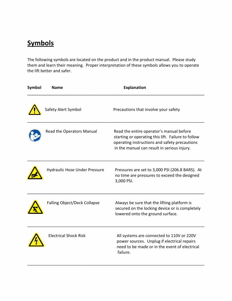
Symbols
The following symbols are located on the product and in the product manual. Please study
them and learn their meaning. Proper interpretation of these symbols allows you to operate
the lift better and safer.
Symbol Name Explanation
______________________________________________________________________________
Safety Alert Symbol Precautions that involve your safety
______________________________________________________________________________
Read the Operators Manual Read the entire operator’s manual before
starting or operating this lift. Failure to follow
operating instructions and safety precautions
in the manual can result in serious injury.
______________________________________________________________________________
Hydraulic Hose Under Pressure Pressures are set to 3,000 PSI (206.8 BARS). At
no time are pressures to exceed the designed
3,000 PSI.
______________________________________________________________________________
Falling Object/Deck Collapse Always be sure that the lifting platform is
secured on the locking device or is completely
lowered onto the ground surface.
______________________________________________________________________________
Electrical Shock Risk All systems are connected to 110V or 220V
power sources. Unplug if electrical repairs
need to be made or in the event of electrical
failure.
______________________________________________________________________________
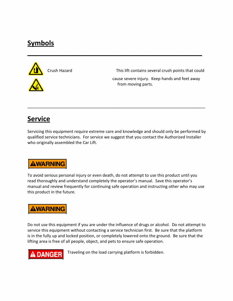
Symbols
______________________________________________
Crush Hazard This lift contains several crush points that could
cause severe injury. Keep hands and feet away
from moving parts.
______________________________________________________________________________
Service
Servicing this equipment require extreme care and knowledge and should only be performed by
qualified service technicians. For service we suggest that you contact the Authorized Installer
who originally assembled the Car Lift.
To avoid serious personal injury or even death, do not attempt to use this product until you
read thoroughly and understand completely the operator’s manual. Save this operator’s
manual and review frequently for continuing safe operation and instructing other who may use
this product in the future.
Do not use this equipment if you are under the influence of drugs or alcohol. Do not attempt to
service this equipment without contacting a service technician first. Be sure that the platform
is in the fully up and locked position, or completely lowered onto the ground. Be sure that the
lifting area is free of all people, object, and pets to ensure safe operation.
Traveling on the load carrying platform is forbidden.
Features and Specifications
Features:
• 100% all galvanized construction
• Commercial grade design and materials
• Dual hydraulic lifting cylinders
• Self-standing, self-supporting unit
• Central or individual hydraulic power packs
• Solid steel platforms prevent dripping of fluids from upper level
• Will accommodate all cars, and some SUV’s depending on ceiling heights
• Available in Tall, Low, Wide, Narrow, and Extra Wide models
Safety:
• Standard key-lock switch for security and safety
• Automatic shut-off if the operator releases the control switch
• Steel-on-steel locks hold the upper platform in place
• Manual lock release required to lower the unit
• Automatic lock reset one the platform has been lowered to ground
• Weight capacity rated to 6,000 lbs DO NOT EXCEED
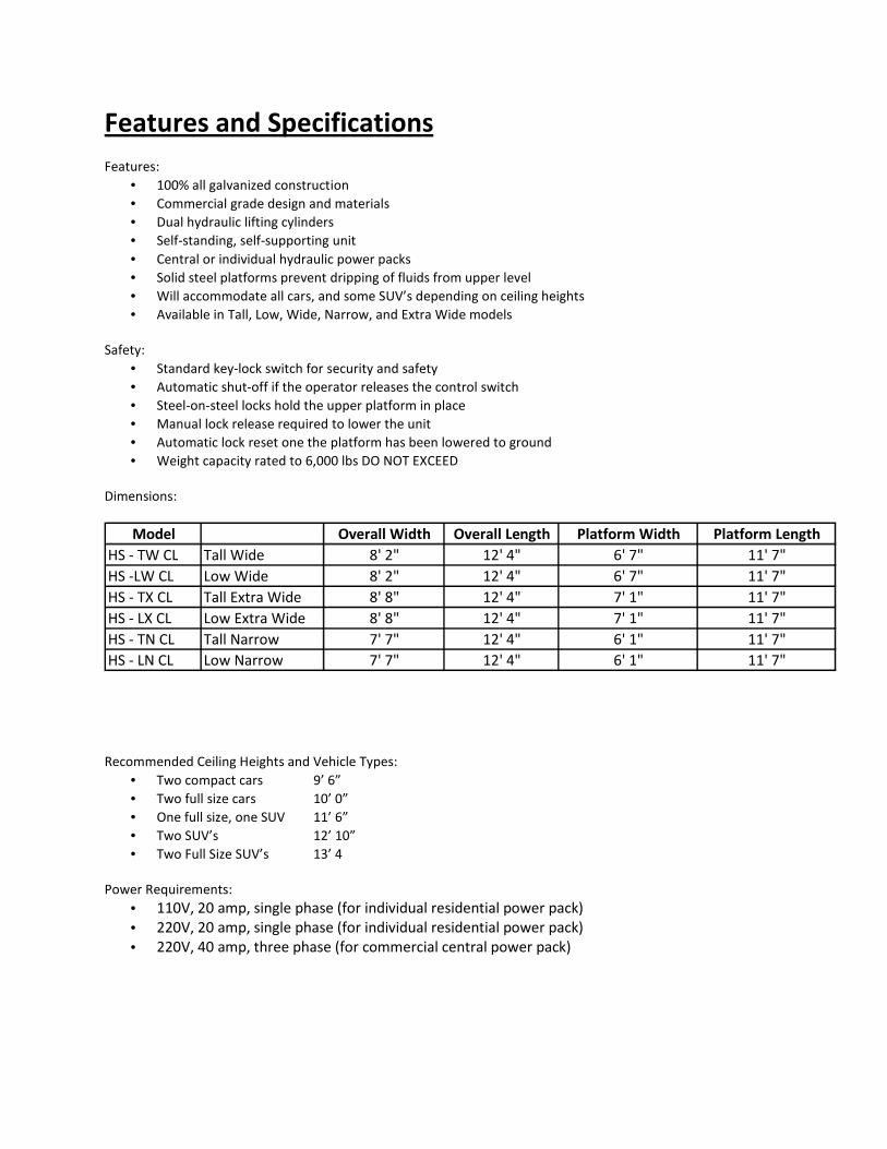
Dimensions:
Model Overall Width Overall Length Platform Width Platform Length
HS - TW CL Tall Wide 8' 2" 12' 4" 6' 7" 11' 7"
HS -LW CL Low Wide 8' 2" 12' 4" 6' 7" 11' 7"
HS - TX CL Tall Extra Wide 8' 8" 12' 4" 7' 1" 11' 7"
HS - LX CL Low Extra Wide 8' 8" 12' 4" 7' 1" 11' 7"
HS - TN CL Tall Narrow 7' 7" 12' 4" 6' 1" 11' 7"
HS - LN CL Low Narrow 7' 7" 12' 4" 6' 1" 11' 7"
Recommended Ceiling Heights and Vehicle Types:
• Two compact cars 9’ 6”
• Two full size cars 10’ 0”
• One full size, one SUV 11’ 6”
• Two SUV’s 12’ 10”
• Two Full Size SUV’s 13’ 4
Power Requirements:
• 110V, 20 amp, single phase (for individual residential power pack)
• 220V, 20 amp, single phase (for individual residential power pack)
• 220V, 40 amp, three phase (for commercial central power pack)
Operation (Residential)
Vehicles must not exceed the maximum height clearance allowed for each upper and lower
vehicle
Be sure that the vehicle is loaded safely and securely, parking brake is engaged, and vehicle is in
park (automatic) or in gear (manual). Be sure that vehicle wheel bases fit securely onto the
lifting platform.
Be sure that all objects, people, pets, and other obstructions are clear of the lifting area.
Do not overload the lifting platform beyond the lifting capacity of the lift (6,000 lbs.)
Always be sure the platform safety locks are completely engaged and hydraulic pressure has
been relieved. Never stop the platform half way up or down. Never leave platform unattended
until movement has completed and the platform is either on the ground completely, or on the
safety locks completely.
PRE-LIFTING STAGE
NOTE: Your Car Lift in most indoor installations will be set for particular vehicles on the top and the bottom. Your lift is set for cars on the upper platform that do not exceed _____inches in height. (This should be filled out at the time of installation)
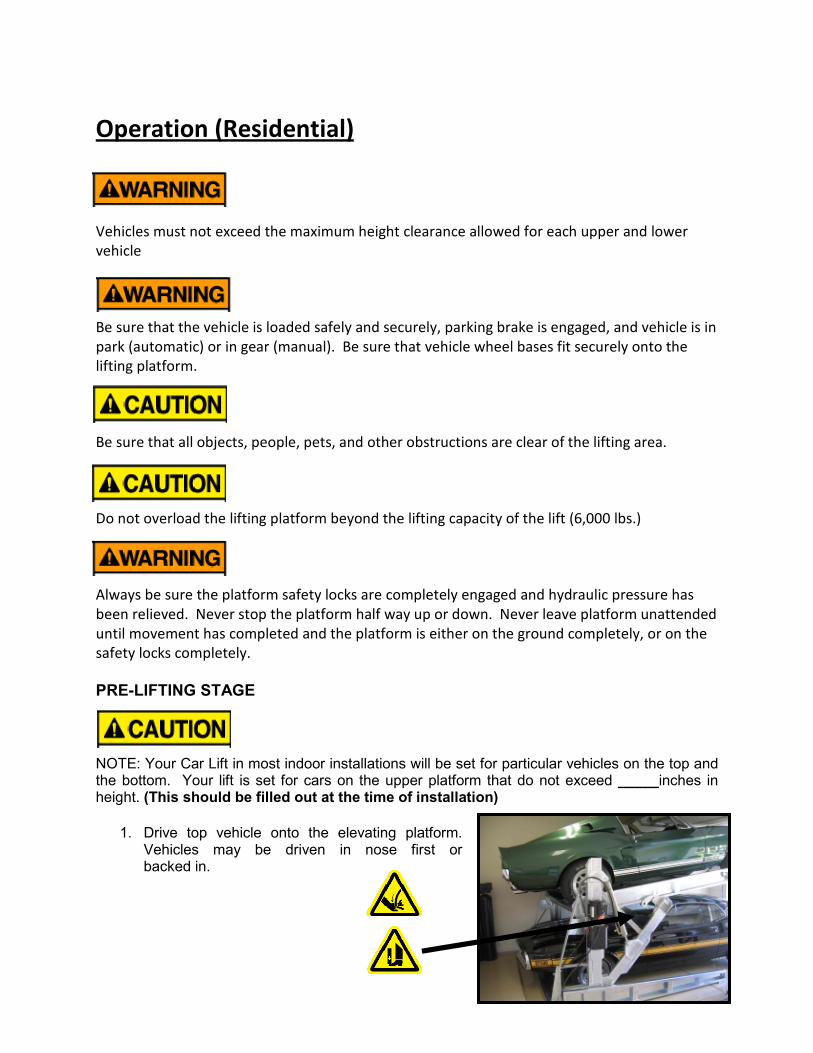
1. Drive top vehicle onto the elevating platform. Vehicles may be driven in nose first or backed in.
2. Drive until the top vehicle's foremost tires drop into the wheel well or rest against the wheel stop (if pulling on forward, this will be the front tires, if pulling in backwards, this will be the rear tires).
3. Turn off car engine, engage safety brake, and place the vehicle’s gear selector in Park. If vehicle is manual shifting, be sure the transmission is in gear.
4. Check the front of the Car Lift to make sure that the vehicle's forward tires are securely set in the wheel well or safely rest against the wheel stop.
5. Walk around Car Lift to ensure nothing is placed on or near the elevating platform.
6. Position yourself beside the lift within reach of the operating switch/key lock..
LIFTING STAGE
1. Once all precautions of the Pre-Lifting Stage (above) are followed, check around Car Lift to ensure that no objects are in the way of the platform, and that no person (except the operator who will be operating the Car Lift) are within 10 feet.
2. Next, turn the key lock to the on position which will allow the lifting controls to be activated. To lift elevating platform depress the button on motor housing to engage the hydraulic power pack. As a safeguard, the button must be engaged at all times during the raising and lowering of the Car Lift. This ensures your complete attention to the surroundings and to the operation of the Car Lift. If the button or lever is released, the Car Lift will automatically stop, hydraulically locked in that position. This locking mechanism is temporary in nature designed for emergency stopping of the lifting motion; over time the hydraulic locks will slowly allow the elevating platform to lower unless the mechanical locks are fully engaged.
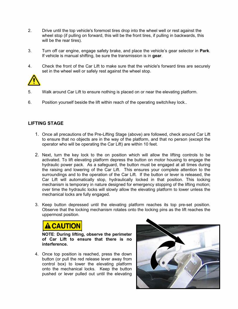
3. Keep button depressed until the elevating platform reaches its top pre-set position. Observe that the locking mechanism rotates onto the locking pins as the lift reaches the uppermost position. NOTE: During lifting, observe the perimeter of Car Lift to ensure that there is no interference.
4. Once top position is reached, press the down button (or pull the red release lever away from control box) to lower the elevating platform onto the mechanical locks. Keep the button pushed or lever pulled out until the elevating
platform is resting securely on the mechanical locking pins and count to 3 seconds. If the mechanical locks are not properly engaged, the elevating pan will lower to the floor. Call for service if this occurs, or follow troubleshooting guide.
5. Walk around, never under, the Car Lift to ensure that both mechanical locks are engaged.
IF ELEVATING PLATFORM IS NOT RESTING SECURELY ON THE MECHANICAL LOCKS, THE BOTTOM VEHICLE, PERSONS OR OTHER OBJECTS UNDERNEATH CAN BE INJURED OR DAMAGED. HARDING STEEL ASSUMES NO RESPONSIBILITY FOR DAMAGE TO PERSONS OR PROPERTY DUE TO THE TOP ELEVATING PLATFORM NOT BEING PROPERLY SECURED ONTO THE MECHANICAL LOCKS. IF THE MECHANICAL LOCKS ARE DAMAGED OR NOT OPERATING PROPERLY, DO NOT USE THE CAR-LIFT UNTIL A CERTIFIED HARDING STEEL TECHNICIAN HAS REPAIRED THE PROBLEM.
PLACEMENT OF LOWER VEHICLE
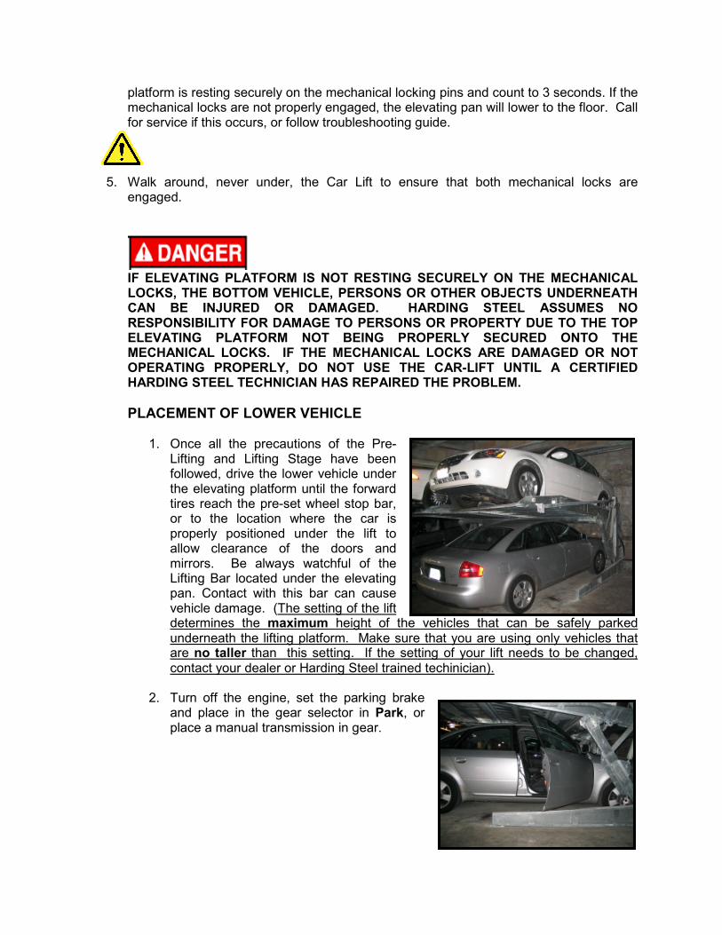
1. Once all the precautions of the Pre-Lifting and Lifting Stage have been followed, drive the lower vehicle under the elevating platform until the forward tires reach the pre-set wheel stop bar, or to the location where the car is properly positioned under the lift to allow clearance of the doors and mirrors. Be always watchful of the Lifting Bar located under the elevating pan. Contact with this bar can cause vehicle damage. (The setting of the lift determines the maximum height of the vehicles that can be safely parked underneath the lifting platform. Make sure that you are using only vehicles that are no taller than this setting. If the setting of your lift needs to be changed, contact your dealer or Harding Steel trained techinician).
2. Turn off the engine, set the parking brake and place in the gear selector in Park, or place a manual transmission in gear.
REMOVAL OF LOWER VEHICLE
1. Back out the lower vehicle and make sure it is well clear of the Car Lift before lowering the elevating platform.
LOWERING THE LIFT
1. Walk around Car Lift to make sure nothing is below or near the elevating platform footprint for descent. Be certain that no person (except the person who will be operating the Car Lift) is within 10 feet of the moving Car Lift.
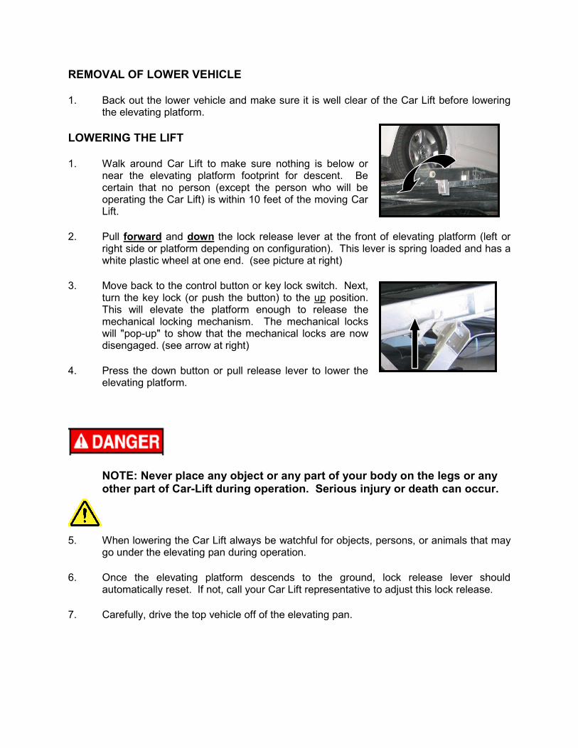
2. Pull forward and down the lock release lever at the front of elevating platform (left or right side or platform depending on configuration). This lever is spring loaded and has a white plastic wheel at one end. (see picture at right)
3. Move back to the control button or key lock switch. Next, turn the key lock (or push the button) to the up position. This will elevate the platform enough to release the mechanical locking mechanism. The mechanical locks will "pop-up" to show that the mechanical locks are now disengaged. (see arrow at right)
4. Press the down button or pull release lever to lower the elevating platform.
NOTE: Never place any object or any part of your body on the legs or any other part of Car-Lift during operation. Serious injury or death can occur.
5. When lowering the Car Lift always be watchful for objects, persons, or animals that may go under the elevating pan during operation.
6. Once the elevating platform descends to the ground, lock release lever should automatically reset. If not, call your Car Lift representative to adjust this lock release.
7. Carefully, drive the top vehicle off of the elevating pan.
Other Operating Tips and Suggestions:
1. Do not raise the elevating pan when the lift is empty. The lifts are designed to be lowered with the weight of the car on the platform. It may take an inordinate amount of time to lower an empty lift.
2. Do not place anything on the corners of the lift platform that may interfere with the clear operation of the lock release mechanism.
3. Do not leave lift unattended when it is partially raised or lowered and not supported by the mechanical locking mechanism.
Operation (Commercial)
Vehicles must not exceed the maximum height clearance allowed for each upper and lower
vehicle
Be sure that the vehicle is loaded safely and securely, parking brake is engaged, and vehicle is in
park (automatic) or in gear (manual). Be sure that vehicle wheel bases fit securely onto the
lifting platform.
Be sure that all objects, people, pets, and other obstructions are clear of the lifting area.
Do not overload the lifting platform beyond the lifting capacity of the lift (6,000 lbs.)
Always be sure the platform safety locks are completely engaged and hydraulic pressure has
been relieved. Never stop the platform half way up or down. Never leave platform unattended
until movement has completed and the platform is either on the ground completely, or on the
safety locks completely.
PRE-LIFTING STAGE
NOTE: Your Car Lift in most indoor installations will be set for particular vehicles on the top and the bottom. Your lift is set for cars on the upper platform that do not exceed _____inches in height..
1. Drive top vehicle onto the elevating pan. Vehicles may be driven in nose first or backed in.
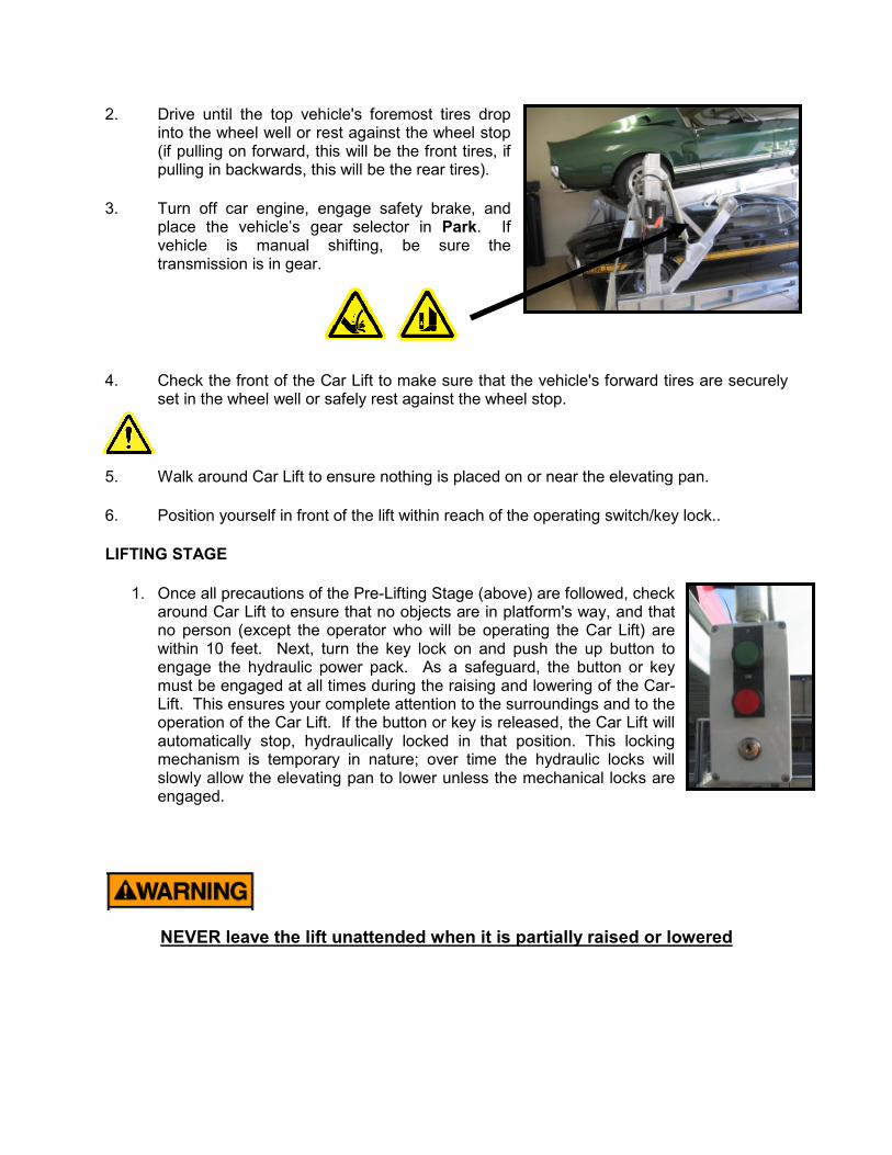
2. Drive until the top vehicle's foremost tires drop into the wheel well or rest against the wheel stop (if pulling on forward, this will be the front tires, if pulling in backwards, this will be the rear tires).
3. Turn off car engine, engage safety brake, and place the vehicle’s gear selector in Park. If vehicle is manual shifting, be sure the transmission is in gear.
4. Check the front of the Car Lift to make sure that the vehicle's forward tires are securely set in the wheel well or safely rest against the wheel stop.
5. Walk around Car Lift to ensure nothing is placed on or near the elevating pan.
6. Position yourself in front of the lift within reach of the operating switch/key lock..
LIFTING STAGE
1. Once all precautions of the Pre-Lifting Stage (above) are followed, check around Car Lift to ensure that no objects are in platform's way, and that no person (except the operator who will be operating the Car Lift) are within 10 feet. Next, turn the key lock on and push the up button to engage the hydraulic power pack. As a safeguard, the button or key must be engaged at all times during the raising and lowering of the Car-Lift. This ensures your complete attention to the surroundings and to the operation of the Car Lift. If the button or key is released, the Car Lift will automatically stop, hydraulically locked in that position. This locking mechanism is temporary in nature; over time the hydraulic locks will slowly allow the elevating pan to lower unless the mechanical locks are engaged.
NEVER leave the lift unattended when it is partially raised or lowered
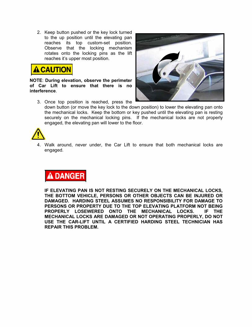
2. Keep button pushed or the key lock turned to the up position until the elevating pan reaches its top custom-set position. Observe that the locking mechanism rotates onto the locking pins as the lift reaches it’s upper most position.
NOTE: During elevation, observe the perimeter of Car Lift to ensure that there is no interference.
3. Once top position is reached, press the down button (or move the key lock to the down position) to lower the elevating pan onto the mechanical locks. Keep the bottom or key pushed until the elevating pan is resting securely on the mechanical locking pins. If the mechanical locks are not properly engaged, the elevating pan will lower to the floor.
4. Walk around, never under, the Car Lift to ensure that both mechanical locks are engaged.
IF ELEVATING PAN IS NOT RESTING SECURELY ON THE MECHANICAL LOCKS, THE BOTTOM VEHICLE, PERSONS OR OTHER OBJECTS CAN BE INJURED OR DAMAGED. HARDING STEEL ASSUMES NO RESPONSIBILITY FOR DAMAGE TO PERSONS OR PROPERTY DUE TO THE TOP ELEVATING PLATFORM NOT BEING PROPERLY LOSEWERED ONTO THE MECHANICAL LOCKS. IF THE MECHANICAL LOCKS ARE DAMAGED OR NOT OPERATING PROPERLY, DO NOT USE THE CAR-LIFT UNTIL A CERTIFIED HARDING STEEL TECHNICIAN HAS REPAIR THIS PROBLEM.
PLACEMENT OF LOWER VEHICLE
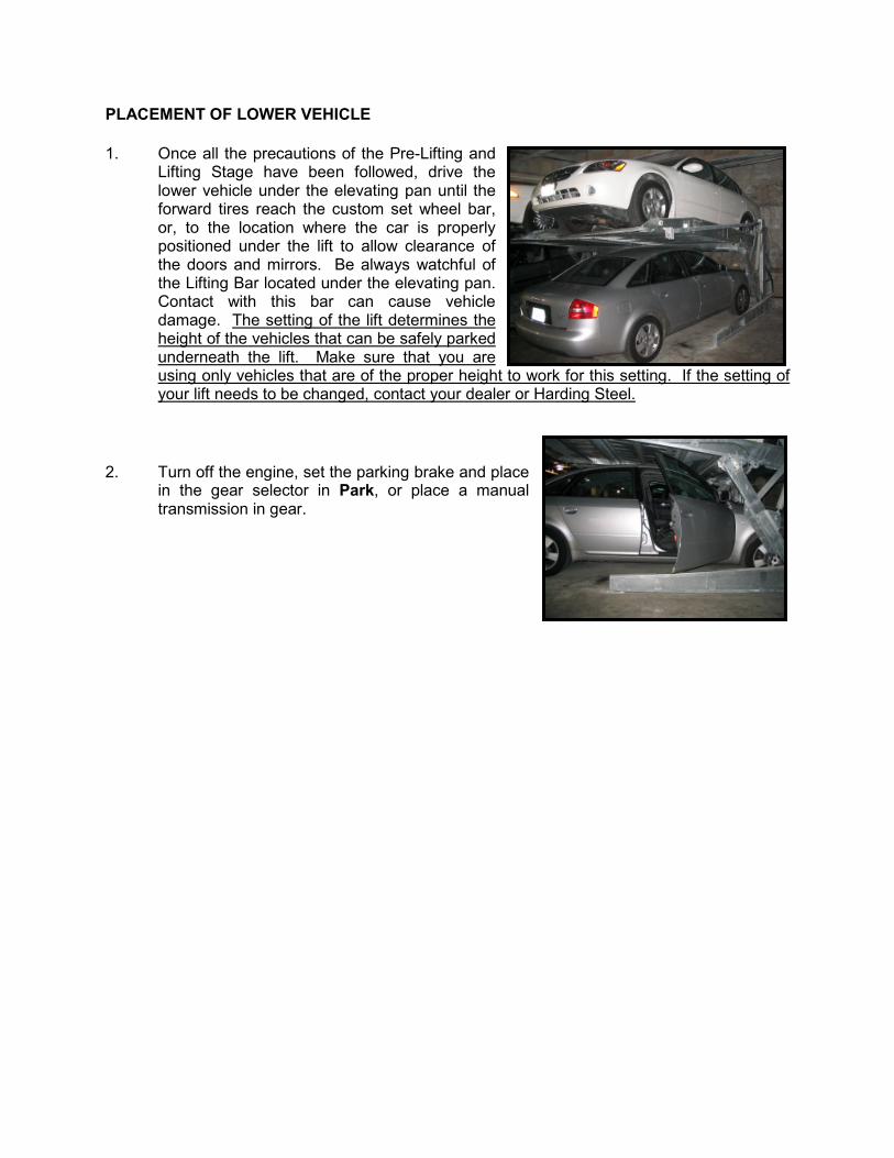
1. Once all the precautions of the Pre-Lifting and Lifting Stage have been followed, drive the lower vehicle under the elevating pan until the forward tires reach the custom set wheel bar, or, to the location where the car is properly positioned under the lift to allow clearance of the doors and mirrors. Be always watchful of the Lifting Bar located under the elevating pan. Contact with this bar can cause vehicle damage. The setting of the lift determines the height of the vehicles that can be safely parked underneath the lift. Make sure that you are using only vehicles that are of the proper height to work for this setting. If the setting of your lift needs to be changed, contact your dealer or Harding Steel.
2. Turn off the engine, set the parking brake and place in the gear selector in Park, or place a manual transmission in gear.
REMOVAL OF LOWER VEHICLE
1. Back out the lower vehicle and make sure it is well clear of the Car Lift before lowering the elevating pan.
LOWERING THE LIFT
1. Walk around Car Lift to make sure nothing is below or near the elevating pan's footprint for descent. Be certain that no person (except the person who will be running the Car Lift) is within 10 feet of the moving Car Lift.
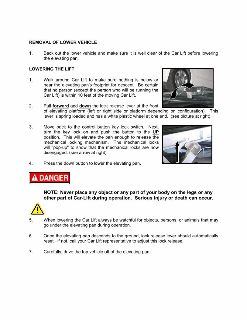
2. Pull forward and down the lock release lever at the front of elevating platform (left or right side or platform depending on configuration). This lever is spring loaded and has a white plastic wheel at one end. (see picture at right)
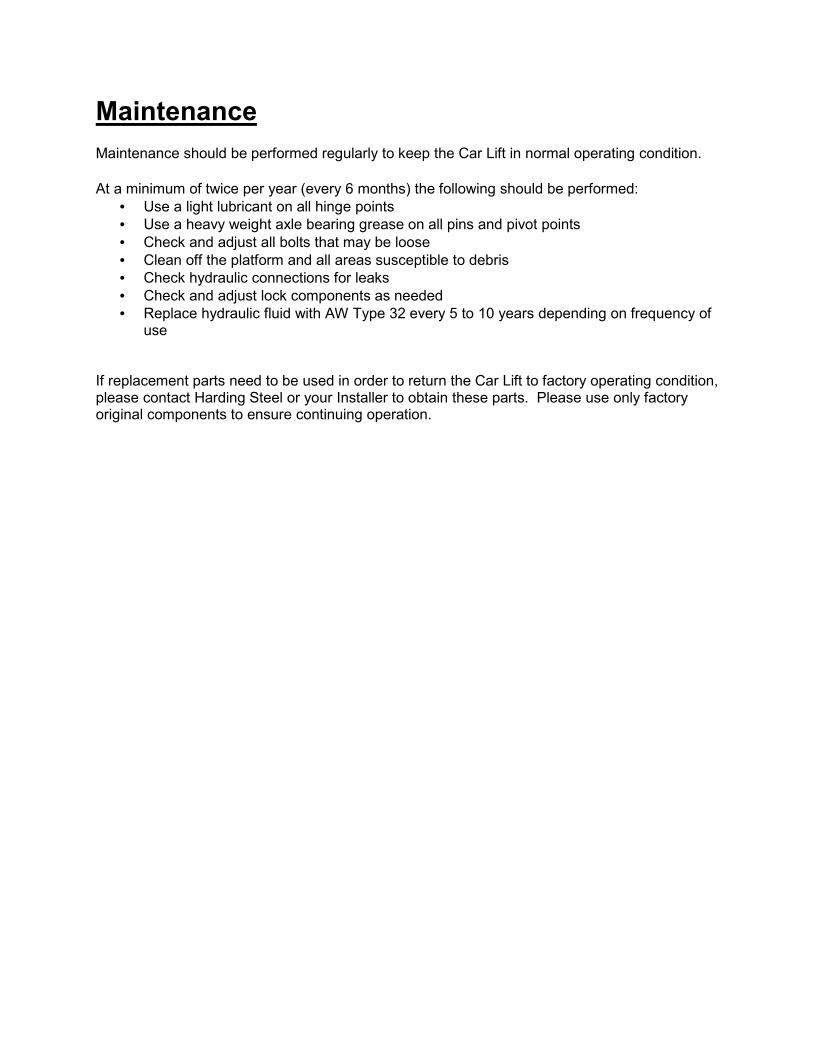
3. Move back to the control button key lock switch. Next, turn the key lock on and push the button to the UP position. This will elevate the pan enough to release the mechanical locking mechanism. The mechanical locks will "pop-up" to show that the mechanical locks are now disengaged. (see arrow at right)
4. Press the down button to lower the elevating pan.
NOTE: Never place any object or any part of your body on the legs or any other part of Car-Lift during operation. Serious injury or death can occur.
5. When lowering the Car Lift always be watchful for objects, persons, or animals that may go under the elevating pan during operation.
6. Once the elevating pan descends to the ground, lock release lever should automatically reset. If not, call your Car Lift representative to adjust this lock release.
7. Carefully, drive the top vehicle off of the elevating pan.
Maintenance
Maintenance should be performed regularly to keep the Car Lift in normal operating condition.
At a minimum of twice per year (every 6 months) the following should be performed:
• Use a light lubricant on all hinge points
• Use a heavy weight axle bearing grease on all pins and pivot points
• Check and adjust all bolts that may be loose
• Clean off the platform and all areas susceptible to debris
• Check hydraulic connections for leaks
• Check and adjust lock components as needed
• Replace hydraulic fluid with AW Type 32 every 5 to 10 years depending on frequency of use
If replacement parts need to be used in order to return the Car Lift to factory operating condition, please contact Harding Steel or your Installer to obtain these parts. Please use only factory original components to ensure continuing operation.
Troubleshooting
Problem Possible Cause Solution
Motor will not start Unit may be unplugged Check power connection
Circuit breaker has been tripped Check circuit breaker is on
Key switch is not in the on position Switch the key on
Motor runs but will not lift Vehicle is too heavy Check weight of vehicle, if over 6,000 lbs
remove and do not try to lift again
Pressure is too low Contact service provider to adjust
pressures
Lift is leaning to one side when
lowering
Flow control valves are not properly
adjusted Do not make any adjustments without
first contacting your service provider. Lift
the platform back up onto the safety locks
and do not use
Lock will not engage Platform is not up all the way Make sure the lift has been lifted above
the lock catch. If not, carefully raise lift
until locks engage.
Lock cable is not properly adjusted Contact your service provider
Lock release wheel did not reset Lower the lift to ground, if it does not
reset, contact your service provider.
Lock will not disengage Lock release wheel has not been pulled Pull lock release before attempting to
lower lift. Read operating instructions
Lock cable is not properly adjusted Contact your service provider
Lift is coming down too fast Flow control valves are not properly
adjusted
Contact your service provider before
making any adjustments
Fluid leaking from cylinders Cylinder seals may be worn out Contact your service provider
Fluid is leaking from the hose Loose connection
Tighten hose fittings until leak subsides
Punctured hose Contact your service provider to replace
the hose.
Product Warranty
Limited Warranty Statement
HARDING STEEL, INC.
730 17th Street, $650
Denver, CO 80202
(800) 878-7888 (303) 762-9500
Original Manufacturer’s WARRANTY HARDING STEEL, INC. (HARDING) warrants all new equipment of its installation to be free from defects in materials
and workmanship for a period of twelve months on all electrical components, twenty four months on all
mechanical components and sixty months for the structural integrity of the unit from the date of completion of
installation.
During the first twelve months of this Warranty period, HARDING includes the replacement of parts or
components and the expense of labor and parts or component required for such replacement. During the second
twelve month period of this Warranty period, the warranty will be restricted to include the furnishing of all non-
electrical replacement parts or components reasonably required, but shall not include the costs of labor which
may be required for repair (or incidental to the replacement of such parts or components furnished) during the
second twelve month period of this Warranty. The structural integrity of the system is warranted, pro rata, for a
period of sixty months for the cost of replacing any structural member, expense of labor shall be as set forth
above.
HARDING is not responsible for vandalism, neglect such as, but not limited to, not putting car tires properly in
wheel stops, not activating and/or releasing the mechanical locks properly, car damages to the cylinders, moving
of system from original installation position, not observing the normal safety precautions or safety devices in use
on systems, or leaving the control panel unlocked when system is unattended. In addition, HARDING is not
responsible for arson, tampering with or modifying the components by unauthorized personnel.
No liability or responsibility whatsoever shall attached to HARDING under this warranty until the systems or goods
are purchased from HARDING and have been paid for in accordance with the agreement for purchase and sale of
said system(s). The periods of Warranty as aforesaid shall elapse and run during all periods in which payments to
HARDING have not been made in accordance with the agreement of purchase. No extension as to the period or
periods of Warranty or terms of the within Warranty will be effective and binding upon HARDING unless made in
writing by letter from HARDING executed by an Officer of HARDING.
THIS WARRANTY IS EXPRESSLY MADE BY HARDING AND ACCEPTED BY THE PURCHASER IN LIEU OF ALL OTHER
WARRANTIES, INCLUDING WARRANTIES OF MERCHANTABILITY AND FITNESS FOR A PARTICULAR PURPOSE,
WHETHER WRITTEN, ORAL, EXPRESSED, IMPLIED OR STATUTORY.
HARDING neither assumes nor authorizes any other person to assume for it any other liabilities with respect to its
equipment.
HARDING shall not be liable for normal wear and tear, nor for any consequential damage or loss of time due to
partial or complete inoperability of its equipment for any reason whatsoever and the terms of the Warranty herein
specified shall be in lieu of an damages and claims of any type whatsoever, except as specifically provided herein.
This Warranty, the interpretation thereof, the laws and statutes interpreting this Warranty and jurisdiction of any
action shall be in Colorado.
This Warranty shall not apply to equipment or parts there of which have been altered or repaired by other than
authorized representatives of HARDING or which have been subject to misuse, neglect, or accident, or to damages
or destruction occasioned by an act of God.
HARDING STEEL, INC.