Embed Size (px)
Citation preview

CAPCOA GHG Rx Protocol:
Organic Waste Digestion Project Protocol
(Based on the Climate Action Reserve, Version 2.1, January 2014)
(Approved by the CAPCOA Board on January 3, 2017)

CAPCOA GHG Rx Protocol: Organic Waste Digestion Project Protocol
The following conditions apply for use in the CAPCOA GHG Rx:
1. Projects must be located in California
2. Projects must commence on or after 1/1/07

Organic Waste DigestionVersion 2.1 | January 16, 2014
Project Protocol

Climate Action Reserve 601 West 5th Street, Suite 650 Los Angeles, CA 90071 www.climateactionreserve.org Released January 16, 2014 © 2014 Climate Action Reserve. All rights reserved. This material may not be reproduced, displayed, modified, or distributed without the express written permission of the Climate Action Reserve.

Organic Waste Digestion Project Protocol Version 2.1, January 2014
Acknowledgements Original Author Syd Partridge Supporting Staff (in alphabetical order) Derik Broekhoff Max DuBuisson Tim Kidman Nancy Kong Sami Osman Heather Raven Rachel Tornek Workgroup Marcia Gowen Trump Atmosclear Keith Driver Blue Source Canada Nick Lapis Californians Against Waste Pierre Loots Cantor CO2e Kevin Eslinger California Air Resources Board Shelby Livingston California Air Resources Board Jack Macy City and County of San Francisco Rowena Romano City of Los Angeles Ronald Lew California Integrated Waste Management Board Rob Janzen Climate Check Paul Relis CR&R Inc. Stephanie Cheng East Bay Municipal Utility District Jay Wintergreen First Environment Adam Penque Greenhouse Gas Services, LLC. Juliette Bohn Humboldt Waste Management Authority Michael Hvisdos Microgy, Inc. Rachel Oster Recology, Inc. Derek Markolf Ryerson, Master and Associates, Inc. Peter Freed Terra Pass Charles Kennedy Tetra Tech Sally Brown University of Washington Chuck White Waste Management Paul Sousa Western United Dairymen

Organic Waste Digestion Project Protocol Version 2.1, January 2014
Table of Contents Abbreviations and Acronyms ...................................................................................................... 1 1 Introduction .......................................................................................................................... 1 2 The GHG Reduction Project ................................................................................................. 2
2.1 Background .................................................................................................................... 2 2.2 Project Definition ............................................................................................................ 2 2.3 The Project Developer .................................................................................................... 3
3 Eligibility Rules ..................................................................................................................... 4 3.1 Location .......................................................................................................................... 4 3.2 Project Start Date ........................................................................................................... 4 3.3 Project Crediting Period .................................................................................................. 5 3.4 Anaerobic Baseline Conditions ....................................................................................... 5
3.4.1 Livestock Manure .................................................................................................... 5 3.4.2 Agro-Industrial Wastewater ..................................................................................... 5 3.4.3 Centralized Digesters .............................................................................................. 6
3.5 Additionality .................................................................................................................... 6 3.5.1 The Performance Standard Test .............................................................................. 6 3.5.2 The Legal Requirement Test ................................................................................... 8
3.6 Regulatory Compliance .................................................................................................10 3.7 Ownership .....................................................................................................................10
4 The GHG Assessment Boundary ........................................................................................12 5 Quantifying GHG Emission Reductions ...............................................................................20
5.1 Quantifying Baseline Emissions.....................................................................................22 5.1.1 Baseline Emissions from Eligible Food and Food-Soiled Paper Waste Streams
(SSR 4) ..................................................................................................................23 5.1.2 Baseline Emissions from Eligible Agro-Industrial Wastewater Streams (SSR 6) .....34 5.1.3 Baseline Emissions from Manure Treatment Systems (SSR 5) ..............................36
5.2 Quantifying Project Emissions .......................................................................................37 5.2.1 Project CO2 Emissions from Fossil Fuel Combustion and Grid Delivered Electricity
(SSRs 3, 8, 13, 15, 17) ...........................................................................................38 5.2.2 Project Emissions from the Biogas Control System (SSRs 9, 10, 11, 12, 14) .........39 5.2.3 Project Methane Emissions from Liquid Digester Effluent Storage and Treatment
(SSR 16) ................................................................................................................42 5.2.4 Project Emissions from Aerobic Treatment of Digestate (SSR 17) ..........................42 5.2.5 Project Emissions from Anaerobic Disposal of Digestate Produced in the Digestion
Process (SSR 18) ...................................................................................................44 5.2.6 Project Emissions from Manure Treatment Systems (SSR 5) .................................44
5.3 Calculating the Total Quantity of Methane Destroyed by the Project .............................45 6 Project Monitoring ...............................................................................................................47
6.1 Organic Waste and Wastewater Monitoring Requirements ............................................47 6.1.1 Food and Food-Soiled Paper Waste Monitoring .....................................................47 6.1.2 Monitoring and Documenting Pre-Project Waste Disposal for Grocery Store Waste
Streams ..................................................................................................................48 6.1.3 Agro-Industrial Wastewater Monitoring ...................................................................49 6.1.4 Digester Effluent and Digestate Monitoring .............................................................50
6.2 Biogas Control System Monitoring .................................................................................51 6.2.1 Biogas Measurement Instrument QA/QC ................................................................53 6.2.2 Missing Data ...........................................................................................................55

Organic Waste Digestion Project Protocol Version 2.1, January 2014
6.3 Monitoring Parameters ..................................................................................................55 7 Reporting Parameters .........................................................................................................69
7.1 Project Submittal Documentation ...................................................................................69 7.2 Record Keeping .............................................................................................................69 7.3 Reporting Period and Verification Cycle ........................................................................70
8 Verification Guidance ..........................................................................................................71 8.1 Standard of Verification .................................................................................................71 8.2 Monitoring Plan .............................................................................................................71 8.3 Verifying Project Eligibility..............................................................................................71 8.4 Core Verification Activities .............................................................................................72 8.5 OWD Verification Items .................................................................................................73
8.5.1 Project Eligibility and CRT Issuance .......................................................................73 8.5.2 Quantification .........................................................................................................75 8.5.3 Risk Assessment ....................................................................................................76
8.6 Completing Verification ..................................................................................................76 9 Glossary of Terms ...............................................................................................................77 10 References ..........................................................................................................................81 Appendix A Associated Environmental Impacts ....................................................................83 Appendix B Data Lookup Tables ...........................................................................................84 Appendix C Development of the Performance Standard .......................................................91 Appendix D Data Substitution................................................................................................99 Appendix E Example Project System Diagram .................................................................... 100

Organic Waste Digestion Project Protocol Version 2.1, January 2014
List of Tables Table 4.1. Description of all Sources, Sinks, and Reservoirs .....................................................14 Table 5.1. Waste Generator Categories and Default Food and Soiled Paper Fractions by Weight
..................................................................................................................................33 Table 5.2. Combined Methane and Nitrous Oxide Emission Factors for Aerobic Treatment of
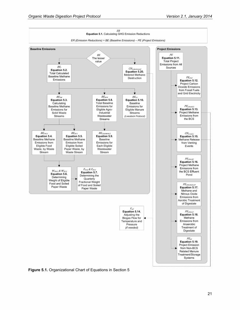
Digestate ...................................................................................................................43 Table 6.1. Organic Waste Digestion Project Monitoring Parameters .........................................56 Table 8.1. Summary of Eligibility Criteria for an Organic Waste Digestion Project .....................72 Table 8.2. Eligibility Verification Items .......................................................................................74 Table 8.3. Quantification Verification Items ...............................................................................75 Table 8.4. Risk Assessment Verification Items ..........................................................................76 Table B.1. Decay Rates (k) by Waste Type and Climate............................................................84 Table B.2. Fraction of Waste Sent to Waste-to-Energy (WTE) Facilities ...................................84 Table B.3. Gas Collection Fractions, by State ...........................................................................85 Table B.4. Digestate Emission Factors by Climate Region ........................................................87 Table B.5. Methane Conversion Factor (MCF) for Wastewater Treatment Systems ..................87 Table B.6. Biogas Collection Efficiency by Digester Type .........................................................87 Table B.7. Biogas Destruction Efficiency Default Values by Destruction Device ........................88 Table B.8. CO2 Emission Factors for Fossil Fuel Use ...............................................................89 Table C.1. Selected Organic Waste Source Industries Studied……………………………………92 Table C.2. Economic Evaluation Guidelines for Digestion Feedstock ........................................97 Table C.3. Example Digester Plant, Payback Economics ..........................................................98 List of Figures Figure 4.1. General illustration of the GHG Assessment Boundary ...........................................13 Figure 5.1. Organizational Chart of Equations in Section 5 .......................................................21 Figure 6.1. Suggested Arrangement of Biogas Metering Equipment .........................................52 Figure B.1. K-Value Categories in the U.S., by County……………………………………………..90
Organic Waste Digestion Project Protocol Version 2.1, January 2014
List of Equations Equation 5.1. Calculating GHG Emission Reductions ...............................................................22 Equation 5.2. Total Calculated Baseline Methane Emissions ....................................................23 Equation 5.3. Calculating Baseline Methane Emissions for Solid Waste Streams (SSR 4) .......24 Equation 5.4. Baseline Methane Emissions from Eligible Food Waste, by Waste Stream .........25 Equation 5.5. Baseline Methane Emissions from Eligible Soiled Paper Waste, by Waste Stream
............................................................................................................................27 Equation 5.6. Determining Weight of Eligible Food and Soiled Paper Waste ............................30 Equation 5.7. Determining the Fraction of Eligible Waste in a Mixed-MSW MRF Fines Waste
Stream ................................................................................................................32 Equation 5.8. Determining the Quarterly Fractional Weight of Food and Soiled Paper Waste ...34 Equation 5.9. Total Baseline Emissions for Eligible Agro-Industrial Wastewater Streams (SSR 6)
............................................................................................................................35 Equation 5.10. Baseline Emissions for Each Eligible Wastewater Stream .................................36 Equation 5.11. Baseline Emissions for Eligible Manure Streams (SSR 5) .................................37 Equation 5.12. Total Project Emissions from All Sources ..........................................................38 Equation 5.13. Project Carbon Dioxide Emissions from Fossil Fuel and Grid Electricity ............39 Equation 5.14. Project Methane Emissions from the BCS (SSRs 9, 10, 11, 12, 14) ..................40 Equation 5.15. Adjusting the Biogas Flow for Temperature and Pressure .................................41 Equation 5.16. Methane Release from Venting Events .............................................................41 Equation 5.17. Project Methane Emissions from the BCS Effluent Pond (SSR 16) ...................42 Equation 5.18. Methane and Nitrous Oxide Emissions from Aerobic Treatment of Digestate
(SSR 17) .............................................................................................................44 Equation 5.19. Methane Emissions from Anaerobic Treatment of Digestate (SSR 18) ..............44 Equation 5.20. Project Emissions from Non-BCS Related Manure Treatment/Storage Systems
............................................................................................................................45 Equation 5.21. Metered Methane Destruction ...........................................................................46

Organic Waste Digestion Project Protocol Version 2.1, January 2014
1
Abbreviations and Acronyms ACF Actual cubic feet
BCS Biogas control system
CDM Clean Development Mechanism
CH4 Methane
CO2 Carbon dioxide
CRT Climate Reserve Tonne
COD Chemical oxygen demand
FOD First Order Decay
GHG Greenhouse gas
MSW Municipal solid waste
MRF Materials Recovery Facility
N2O Nitrous oxide
OWC Organic Waste Composting
OWD Organic Waste Digestion
POTW Publicly owned treatment works
Reserve Climate Action Reserve
SCF Standard cubic feet
SSO Source separated organics
SSRs Sources, sinks, and reservoirs
t Metric ton (or tonne)
UNFCCC United Nations Framework Convention on Climate Change
WW Wastewater
WWTP Wastewater treatment plant

Organic Waste Digestion Project Protocol Version 2.1, January 2014
1
1 Introduction The Climate Action Reserve (Reserve) Organic Waste Digestion (OWD) Project Protocol provides guidance to account for, report, and verify greenhouse gas (GHG) emission reductions associated with the diversion of organic waste and/or wastewater away from anaerobic treatment and disposal systems and to a biogas control system (BCS). For the purposes of this protocol, a biogas control system consists of an anaerobic digester, a biogas collection and monitoring system, and one or more biogas destruction devices.1 Eligible organic waste and/or wastewater streams can be separately-digested, co-digested together, or co-digested in combination with livestock manure.2 Project developers that co-digest eligible organic waste and/or wastewater sources together with livestock manure must use this protocol together with the most current version (as of the date of project listing) of the Climate Action Reserve’s Livestock Project Protocol. As the premier carbon offset registry for the North American carbon market, the Climate Action Reserve encourages action to reduce greenhouse gas (GHG) emissions by ensuring the environmental integrity and financial benefit of emissions reduction projects. The Reserve establishes high quality standards for carbon offset projects, oversees independent third-party verification bodies, issues carbon credits generated from such projects and tracks the transaction of credits over time in a transparent, publicly-accessible system. The Reserve offsets program demonstrates that high-quality carbon offsets foster real reductions in GHG pollution, support activities that reduce local air pollution, spur growth in new green technologies and allow emission reduction goals to be met at lower cost. The transparent processes, multi-stakeholder participation and rigorous standards of the Reserve help earn confidence that registered emissions reductions are real, additional, verifiable, enforceable and permanent. The Reserve’s expertise and insight helped inform the development of the State of California’s cap-and-trade program, which adopted four of the Reserve’s protocols for use in its regulation. The Climate Action Reserve is a private 501(c)(3) nonprofit organization based in Los Angeles, California .3 Project developers that initiate OWD projects use this document to quantify and register GHG reductions with the Reserve. The protocol provides eligibility rules, methods to calculate reductions, performance-monitoring instructions, and procedures for reporting project information to the Reserve. Additionally, all project reports receive at least annual, independent verification by ISO-accredited and Reserve-approved verification bodies. Guidance for verification bodies to verify reductions is provided in the Reserve Verification Program Manual and Section 8 of this protocol. This protocol is designed to ensure the complete, consistent, transparent, accurate, and conservative quantification and verification of GHG emission reductions associated with an OWD project.4
1 Eligible destruction options include both onsite destruction or offsite destruction 2 Eligible organic waste streams are those that meet the “performance standard” threshold specified in Section 3.5.1 of this protocol 3 For more information, please visit www.climateactionreserve.org. 4 See the WRI/WBCSD GHG Protocol for Project Accounting (Part I, Chapter 4) for a description of GHG reduction project accounting principles.
Organic Waste Digestion Project Protocol Version 2.1, January 2014
2
2 The GHG Reduction Project
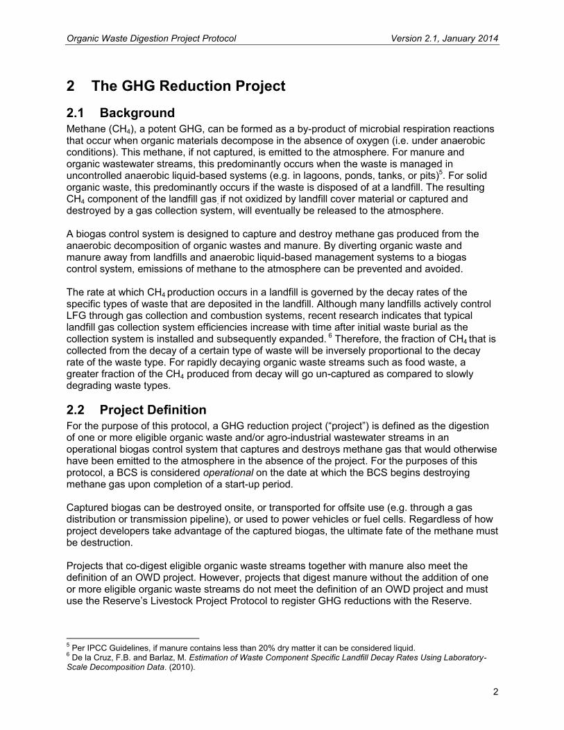
2.1 Background Methane (CH4), a potent GHG, can be formed as a by-product of microbial respiration reactions that occur when organic materials decompose in the absence of oxygen (i.e. under anaerobic conditions). This methane, if not captured, is emitted to the atmosphere. For manure and organic wastewater streams, this predominantly occurs when the waste is managed in uncontrolled anaerobic liquid-based systems (e.g. in lagoons, ponds, tanks, or pits)5. For solid organic waste, this predominantly occurs if the waste is disposed of at a landfill. The resulting CH4 component of the landfill gas, if not oxidized by landfill cover material or captured and destroyed by a gas collection system, will eventually be released to the atmosphere. A biogas control system is designed to capture and destroy methane gas produced from the anaerobic decomposition of organic wastes and manure. By diverting organic waste and manure away from landfills and anaerobic liquid-based management systems to a biogas control system, emissions of methane to the atmosphere can be prevented and avoided. The rate at which CH4 production occurs in a landfill is governed by the decay rates of the specific types of waste that are deposited in the landfill. Although many landfills actively control LFG through gas collection and combustion systems, recent research indicates that typical landfill gas collection system efficiencies increase with time after initial waste burial as the collection system is installed and subsequently expanded. 6 Therefore, the fraction of CH4 that is collected from the decay of a certain type of waste will be inversely proportional to the decay rate of the waste type. For rapidly decaying organic waste streams such as food waste, a greater fraction of the CH4 produced from decay will go un-captured as compared to slowly degrading waste types.
2.2 Project Definition For the purpose of this protocol, a GHG reduction project (“project”) is defined as the digestion of one or more eligible organic waste and/or agro-industrial wastewater streams in an operational biogas control system that captures and destroys methane gas that would otherwise have been emitted to the atmosphere in the absence of the project. For the purposes of this protocol, a BCS is considered operational on the date at which the BCS begins destroying methane gas upon completion of a start-up period. Captured biogas can be destroyed onsite, or transported for offsite use (e.g. through a gas distribution or transmission pipeline), or used to power vehicles or fuel cells. Regardless of how project developers take advantage of the captured biogas, the ultimate fate of the methane must be destruction. Projects that co-digest eligible organic waste streams together with manure also meet the definition of an OWD project. However, projects that digest manure without the addition of one or more eligible organic waste streams do not meet the definition of an OWD project and must use the Reserve’s Livestock Project Protocol to register GHG reductions with the Reserve.
5 Per IPCC Guidelines, if manure contains less than 20% dry matter it can be considered liquid. 6 De la Cruz, F.B. and Barlaz, M. Estimation of Waste Component Specific Landfill Decay Rates Using Laboratory-Scale Decomposition Data. (2010).

Organic Waste Digestion Project Protocol Version 2.1, January 2014
3
Centralized digesters that digest eligible waste streams from more than one source also meet the definition of an OWD project. Similarly, existing digesters at municipal wastewater treatment plants that use excess capacity to co-digest or single-digest eligible organic waste streams also meet the definition of an OWD project. An eligible waste stream is one that:
1. Consists of municipal solid waste (MSW) food waste, non-recyclable MSW food-soiled paper waste, or agro-industrial wastewater streams as defined in Section 3.5.1; and
2. Continually passes the Legal Requirement Test criteria as outlined in Section 3.5.2.
2.3 The Project Developer The “project developer” is an entity that has an active account on the Reserve, submits a project for listing and registration with the Reserve, and is ultimately responsible for all project reporting and verification. Project developers may be agribusiness owners and operators, such as dairy or swine farmers, cheese producers, or food or agricultural processing plant operators. They may also be other entities, such as renewable power developers, municipalities, or waste management entities.
Organic Waste Digestion Project Protocol Version 2.1, January 2014
4
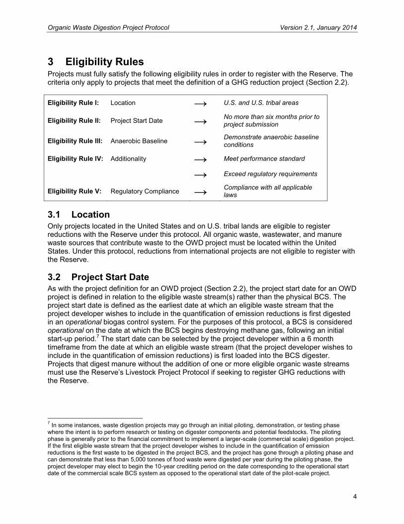
3 Eligibility Rules Projects must fully satisfy the following eligibility rules in order to register with the Reserve. The criteria only apply to projects that meet the definition of a GHG reduction project (Section 2.2). Eligibility Rule I: Location → U.S. and U.S. tribal areas
Eligibility Rule II: Project Start Date → No more than six months prior to project submission
Eligibility Rule III: Anaerobic Baseline → Demonstrate anaerobic baseline conditions
Eligibility Rule IV: Additionality → Meet performance standard
→ Exceed regulatory requirements
Eligibility Rule V: Regulatory Compliance → Compliance with all applicable laws
3.1 Location Only projects located in the United States and on U.S. tribal lands are eligible to register reductions with the Reserve under this protocol. All organic waste, wastewater, and manure waste sources that contribute waste to the OWD project must be located within the United States. Under this protocol, reductions from international projects are not eligible to register with the Reserve.
3.2 Project Start Date As with the project definition for an OWD project (Section 2.2), the project start date for an OWD project is defined in relation to the eligible waste stream(s) rather than the physical BCS. The project start date is defined as the earliest date at which an eligible waste stream that the project developer wishes to include in the quantification of emission reductions is first digested in an operational biogas control system. For the purposes of this protocol, a BCS is considered operational on the date at which the BCS begins destroying methane gas, following an initial start-up period.7 The start date can be selected by the project developer within a 6 month timeframe from the date at which an eligible waste stream (that the project developer wishes to include in the quantification of emission reductions) is first loaded into the BCS digester. Projects that digest manure without the addition of one or more eligible organic waste streams must use the Reserve’s Livestock Project Protocol if seeking to register GHG reductions with the Reserve.
7 In some instances, waste digestion projects may go through an initial piloting, demonstration, or testing phase where the intent is to perform research or testing on digester components and potential feedstocks. The piloting phase is generally prior to the financial commitment to implement a larger-scale (commercial scale) digestion project. If the first eligible waste stream that the project developer wishes to include in the quantification of emission reductions is the first waste to be digested in the project BCS, and the project has gone through a piloting phase and can demonstrate that less than 5,000 tonnes of food waste were digested per year during the piloting phase, the project developer may elect to begin the 10-year crediting period on the date corresponding to the operational start date of the commercial scale BCS system as opposed to the operational start date of the pilot-scale project.

Organic Waste Digestion Project Protocol Version 2.1, January 2014
5
To be eligible, the project must be submitted to the Reserve no more than six months after the project start date.8 Projects may always be submitted for listing by the Reserve prior to their start date. Any BCS will be eligible to host a project, as there are no eligibility requirements pertaining to the BCS itself; however, only waste streams that were first digested in the project BCS no more than six months prior to the project start date will be eligible.
3.3 Project Crediting Period The crediting period for OWD projects under this protocol is ten years. At the end of a project’s first crediting period, project developers may apply for eligibility under a second crediting period. However, the Reserve will cease to issue Climate Reserve Tonnes (CRTs) for GHG reductions associated with eligible waste streams if at any point in the future, the diversion of those waste streams becomes legally required, as defined by the terms of the Legal Requirement Test (see Section 3.5.2), unless the waste stream passes the Legal Requirement Test for Local Waste Diversion Mandates, as specified in Section 3.5.2.1 below. Thus, the Reserve will issue CRTs for GHG reductions quantified and verified according to this protocol for a maximum of two ten year crediting periods after the project start date, or until the project activity is required by law (based on the date that a legal mandate takes effect), whichever comes first. Section 3.5.1 describes requirements for qualifying for a second crediting period.
3.4 Anaerobic Baseline Conditions Developers of projects that digest agro-industrial wastewater streams and/or manure streams must demonstrate that the depth of the anaerobic wastewater and/or manure treatment ponds and lagoons prior to the project’s implementation were sufficient to prevent algal oxygen production and create an oxygen-free bottom layer; which means at least 1 meter depth.9 In the event that the pre-project wastewater treatment system is located at a facility other than where the project is located, and is owned and/or operated by an entity other than the project developer, the project developer shall ensure that the verifier has access to all necessary data and has access to the site where the pre-project wastewater treatment system is located.
3.4.1 Livestock Manure Projects accepting livestock manure shall refer to the most recent version of the Livestock Project Protocol10 at the time of submittal. All manure streams must meet the additionality criteria of that version of the Livestock protocol to be eligible under the OWD protocol. Where there are any inconsistencies between requirements in this protocol and the relevant version of the Livestock protocol, this protocol shall prevail.
3.4.2 Agro-Industrial Wastewater Agro-Industrial wastewater sourced from new agro-industrial facilities (i.e. facilities that have not previously generated wastewater) is not eligible. To be eligible, the project must be able to
8 Projects are considered submitted when the project developer has fully completed, uploaded, and submitted the appropriate Project Submittal Form, available on the Reserve’s website, through their account in the Climate Action Reserve. 9 This is consistent with the United Nations Framework Convention on Climate Change (UNFCCC) Clean Development Mechanism (CDM) methodologies ACM0010 and ACM0014 (available at http://cdm.unfccc.int/methodologies/PAmethodologies/approved.html). For additional information on the design and maintenance of anaerobic wastewater treatment systems, see U.S. Department of Agriculture Natural Resources Conservation Service, Conservation Practice Standard, Waste Storage Facility, No. 313; and U.S. Department of Agriculture Natural Resources Conservation Service, Conservation Practice Standard, Waste Treatment Lagoon, No. 359. 10 Available for download at: http://www.climateactionreserve.org/how/protocols/us-livestock/.

Organic Waste Digestion Project Protocol Version 2.1, January 2014
6
demonstrate that the agro-industrial wastewater stream was previously managed in an open, anaerobic lagoon as described in the first paragraph of Section 3.4 above. This requirement differs from the Livestock Protocol guidance for Greenfield projects due to differences in common practice management identified in the performance standard research described in Appendix C. Because use of open, anaerobic lagoons for wastewater management is less prevalent for agro-industrial wastewater streams, the test for additionality is more stringent.
3.4.3 Centralized Digesters For projects that employ a centralized digester that will be accepting manure or wastewater from more than one source, each individual source of manure or wastewater (identified by the facility from which it is sourced) must meet the anaerobic baseline requirements as of the date that the particular waste stream was first delivered to the project, or demonstrate that the relevant waste stream was previously deemed to be an eligible waste stream at another project that is registered (i.e. has been successfully verified) with the Reserve. In other words, if a new facility begins sending manure or wastewater to the project digester after the project start date, the anaerobic baseline of that manure or wastewater must be assessed as of the date of initial delivery. For projects that employ a centralized digester that will be accepting eligible source separated organics (SSO) grocery store waste, each such waste stream must meet the additionality requirements set out in Section 3.5.1 below, at the time the waste was first delivered to the project.
3.5 Additionality The Reserve strives to register only projects that yield surplus GHG reductions that are additional to what would have occurred in the absence of a carbon offset market. Projects must satisfy the following tests to be considered additional:
1. The Performance Standard Test 2. The Legal Requirement Test
3.5.1 The Performance Standard Test Projects pass the Performance Standard Test by meeting a performance threshold, i.e. a standard of performance applicable to all organic waste digestion projects, established by this protocol. OWD projects may digest numerous potential feedstocks. The performance standard for this protocol defines those feedstocks that the Reserve has determined are highly likely to result in methane emissions under common practice or “business as usual” management practices.11 Only OWD projects that digest one of these feedstocks in a biogas control system are deemed to exceed common practice and are therefore eligible for registration under this protocol. An OWD project passes the Performance Standard Test only if one or more of the following eligible organic waste streams are consistently, periodically, or seasonally digested in the project’s biogas control system:
Municipal Solid Waste (MSW) Food Waste: Non-industrial food waste commonly disposed of in a MSW system, consisting of uneaten food, food scraps, spoiled food and
11 A summary of the study used to establish this list of feedstocks and define this protocol’s performance standard is provided in Appendix C.

Organic Waste Digestion Project Protocol Version 2.1, January 2014
7
food preparation wastes from homes, restaurants, kitchens, grocery stores, campuses, cafeterias, or similar institutions.
Food-Soiled Paper Waste: Non-recyclable paper items that are co-mingled with eligible
food waste, consisting of paper napkins and tissues, paper plates, paper cups, fast food wrappers, used pizza boxes, wax-coated cardboard, and other similar paper or compostable packaging12 items typically disposed of in a MSW system.
Agro-industrial Wastewater: Organic loaded wastewater from industrial or agricultural
processing operations that, prior to the project, was treated in an uncontrolled anaerobic lagoon, pond, or tank at a privately owned treatment facility. Excluded from eligibility based on the Reserve’s performance standard analysis are wastewaters produced at breweries, ethanol plants, pharmaceutical production facilities, and pulp and paper plants.
The Reserve’s performance standard research indicates that approximately 2.8% of the MSW food waste generated in the U.S. is diverted from landfills annually as common practice, and that this is limited mostly to MSW food waste from grocery stores and supermarket diversion programs.13 Therefore, MSW food waste and food-soiled paper waste streams are not eligible if they are sourced from grocery stores and/or supermarkets that have historically diverted these waste streams from landfills. Projects must demonstrate the eligibility of each new grocery store waste stream digested by the project by documenting that the food and food-soiled paper component of the grocery store waste was being disposed of in a landfill for a period of at least 36 months prior to the date that the grocery store waste was first delivered to the project digester, or documenting that the grocery store waste stream was previously deemed to be an eligible waste stream at another OWD or OWC project that is registered with the Reserve. Waste streams originating from new grocery store facilities are deemed eligible. Section 6.1.2 provides requirements for documenting the pre-project disposal of grocery store waste. All other MSW food and food-soiled paper waste sources described above are eligible. OWD projects may choose to digest multiple feedstocks, some of which may be ineligible per the Performance Standard Test. Ineligible waste streams, e.g. fats, oils, and greases (FOG) residues and municipal biosolids (sludge), may be co-digested alongside eligible organic waste streams. However, any methane produced by these waste streams and destroyed by the project will not be eligible for crediting with CRTs by the Reserve. The Performance Standard Test is applied at the time a project applies for registration with the Reserve. Eligible waste streams at the time a project is registered shall remain eligible throughout a project’s first crediting period, regardless of changes in any future versions of this protocol. However, projects must demonstrate the eligibility of all new grocery store waste streams digested by the project according to the requirements above.
12 Non-paper compostable packaging products such as polyactide polymer (PLA) may replace paper or plastic packaging on some food products, and are assumed to have similar properties to soiled paper. 13 Based on composting data supplied by the stakeholder work group that advised development of the Reserve’s Organic Waste Composting protocol, and evidence from compost experts.

Organic Waste Digestion Project Protocol Version 2.1, January 2014
8
If a project developer wishes to apply for a second crediting period, the project must meet the eligibility requirements of the most current version of this protocol, including any updates to the Performance Standard Test.
3.5.2 The Legal Requirement Test All projects are subject to a Legal Requirement Test to ensure that the GHG reductions achieved by a project would not otherwise have occurred due to federal, state, or local regulations, or other legally binding mandates. For OWD projects, the Legal Requirement Test is applied to each eligible waste stream digested by the project. A waste stream passes the Legal Requirement Test when:
1. There are no laws, statutes, regulations, court orders, environmental mitigation agreements, permitting conditions, or other legally binding mandates that require the diversion of the eligible waste stream from landfills, and/or that require the aerobic treatment or anaerobic digestion of the waste stream (see Sections 3.5.2.2 and 3.5.2.3, below, for further guidance on regulations affecting organic solid waste and industrial wastewater streams); or
2. The waste stream passes the Legal Requirement Test for Local Waste Diversion Mandates, as specified in Section 3.5.2.1 below.
To satisfy the Legal Requirement Test, project developers must submit a signed Attestation of Voluntary Implementation form14 prior to the commencement of verification activities each time the project is verified (see Section 8). In addition, the project’s Monitoring Plan (Section 6) must include procedures that the project developer will follow to ascertain and demonstrate that the project (and its associated waste streams) at all times passes the Legal Requirement Test. If an OWD project digests an eligible organic waste stream that later becomes subject to a legal mandate requiring its diversion and/or aerobic treatment or anaerobic digestion, the organic waste stream will remain eligible up until the date that the legal mandate takes effect, unless the waste stream passes the Legal Requirement Test for Local Waste Diversion Mandates as specified in Section 3.5.2.1. Food and/or food-soiled paper waste streams that meet the requirements under Section 3.5.2.1 will remain eligible for the remainder of the crediting period, or until failure of the Legal Requirement Test with regards to state and/or federal regulations. If an OWD project digests an eligible organic waste stream originating from a facility whose methane emissions are later included under an emissions cap (e.g. under a state or federal cap-and-trade program), the organic waste stream will remain eligible until the date that the emissions cap takes effect. If an eligible organic waste stream digested by an OWD project becomes subject to a legally binding mandate requiring its diversion, anaerobic digestion, or aerobic treatment, the project may continue to report GHG reductions to the Reserve associated with other eligible waste streams that are not subject to such mandates. The Reserve will continue to issue CRTs for destruction of methane associated with the digestion of eligible waste streams that are not legally required to be diverted, anaerobically digested or aerobically treated.
14 Attestation forms are available at http://www.climateactionreserve.org/how/program/documents/.
Organic Waste Digestion Project Protocol Version 2.1, January 2014
9
3.5.2.1 Legal Requirement Test for Local Waste Diversion Mandates Local jurisdictions may have bans on certain types of waste going to landfill, or may have mandatory ordinances that require the diversion of organic solid wastes from landfills. If a local jurisdiction has established a mandatory ban on food waste and/or food-soiled paper disposal at landfills, or otherwise has enacted food and/or food-soiled paper waste diversion mandates, the food and/or food-soiled paper waste streams subject to the local diversion mandate passes the Legal Requirement Test if (and only if):
1. The project digesting the local food and/or food-soiled paper waste stream has an operational start date no later than 6 months after the date that the food waste diversion mandate is passed into law; and
2. The food and/or food-soiled paper waste stream continues to pass the Legal Requirement Test with regards to state and federal regulations.
3.5.2.2 Guidance on Solid Organic Waste Regulations There are various state and local regulations, ordinances, and mandatory diversion targets that may obligate waste source producers or waste management entities to divert organic wastes away from landfills. An organic solid waste stream that is banned from landfilling, or is mandated to be managed in a system other than a landfill, fails the Legal Requirement Test.
State Regulations States may have mandatory landfill diversion targets that require a percentage of waste generated to be diverted from landfills to alternative management systems. Although waste diversion targets may not specify a reduction or percentage of diversion that must be met from organic waste, these targets nevertheless provide strong regulatory incentives to divert all wastes (including organic) from landfills. Thus, organic waste originating from a jurisdiction that is not in compliance with a mandated landfill diversion target does not pass the Legal Requirement Test until the date at which the jurisdiction comes into compliance with the mandated landfill diversion target. Mandatory state diversion targets are not to be confused with state diversion goals. Should a state adopt a statewide waste diversion goal that does not impose penalties on jurisdictions for failing to meet diversion targets, then this state goal would not result in a failure of the Legal Requirement Test.
Local and Municipal Regulations and Ordinances Local jurisdictions may have bans on certain types of waste going to landfill, or may have mandatory ordinances that require the diversion of organic solid wastes from landfills. If a local jurisdiction has established a mandatory ban on food waste disposal at landfills, or otherwise has enacted food waste diversion mandates, food waste streams originating from the jurisdiction fail the Legal Requirement Test.
3.5.2.3 Guidance on Industrial Wastewater Regulations
Federal Regulations There are several federal regulations and standards for industrial wastewater discharge and pre-treatment. For example, Title 40 of the Code of Federal Regulations establishes pre-treatment standards for 35 different categories of industrial facilities. As of the date of adoption of this protocol, however, no federal regulations or standards require the installation of a BCS at
Organic Waste Digestion Project Protocol Version 2.1, January 2014
10
industrial wastewater facilities, or the control of methane emissions to the atmosphere, so these regulations and standards do not affect application of the Legal Requirement Test.
State, Local, and Municipal Regulations State regulations must be at least as stringent as any federal requirement, but states can adopt more stringent and additional requirements as well. Wastewater regulations vary between states and even between counties or cities within a single state. For example, the East Bay Municipal Utility District (EBMUD) in California sets Total Suspended Solids (TSS) limits between 30 and 3,500 mg/l depending on the industry while Sheboygan and Waukesha, Wisconsin set TSS limits at 234 and 340 mg/l, respectively. Each of these localities also sets different fees that are applied to discharges when wastewater pollution limits are exceeded. Limits and discharge fees range from a few thousand to a few million dollars, thereby encouraging reduction of wastewater discharges with a combination of prescriptive controls and economic motivation. Although certain regions may encourage reduction of wastewater discharge into public treatment systems through combination of lower discharge limits and higher fees, there are no regulations known as of the date of adoption of this protocol that specifically require the installation of a BCS at industrial wastewater facilities, or the control of methane emissions to the atmosphere.
3.6 Regulatory Compliance As a final eligibility requirement, project developers must attest that project activities do not cause material violations of applicable laws (e.g. air, water quality, safety, etc.). To satisfy this requirement, project developers must submit a signed Attestation of Regulatory Compliance form15 prior to the commencement of verification activities each time the project is verified. Project developers are also required to disclose in writing to the verifier any and all instances of legal violations – material or otherwise – caused by the project or project activities. A violation should be considered to be “caused” by project activities if it can be reasonably argued that the violation would not have occurred in the absence of the project activities. The project developer shall disclose all instances of violations to the verifier and the verifier will then determine whether the requisite causality exists. If a verifier finds that project activities have caused a material violation, then CRTs will not be issued for GHG reductions that occurred during the period(s) when the violation occurred. Individual violations due to administrative or reporting issues, or due to “acts of nature,” are not considered material and will not affect CRT crediting. However, recurrent administrative violations directly related to project activities may affect crediting. Verifiers must determine if recurrent violations rise to the level of materiality. If the verifier is unable to assess the materiality of the violation, then the verifier shall consult with the Reserve.
3.7 Ownership The project developer must attest to the Reserve that they have exclusive claim to the GHG reductions – including indirect emission reductions – resulting from the project. Indirect emission reductions are reductions in GHG emissions that occur at a location other than where the reduction activity is implemented, and/or at sources not owned or controlled by project participants. An OWD project may result in indirect emission reductions if it diverts organic waste streams away from landfills or wastewater treatment systems that are not located at the project site or that are not owned or controlled by project participants. Each time a project is verified, the project developer must attest that no other entities are reporting or claiming (e.g. for 15 Attestation forms are available at http://www.climateactionreserve.org/how/program/documents/.

Organic Waste Digestion Project Protocol Version 2.1, January 2014
11
voluntary reporting or regulatory compliance purposes) the GHG reductions caused by the project.16 The Reserve will not issue CRTs for GHG reductions that are reported or claimed by entities other than the project developer (e.g. waste generators, landfills, municipalities or others not designated as the project developer). If an OWD project is receiving credits or incentive payments of any kind in addition to CRTs, the project developer needs to demonstrate that double claiming of emission reductions is not occurring. The project developer must demonstrate to the verifier that the party (or parties) providing those payments/credits are not directly or indirectly asserting any claim (legal or otherwise) to the project’s emission reductions. The project developer should provide the verifier with any Terms of Reference, contracts, program rules, etc., associated with the granting of the payments/credits.
16 This is done by signing the Reserve’s Attestation of Title form, available at http://www.climateactionreserve.org/how/program/documents/.

Organic Waste Digestion Project Protocol Version 2.1, January 2014
12
4 The GHG Assessment Boundary The GHG Assessment Boundary delineates the GHG sources, sinks, and reservoirs (SSRs) that must be assessed by project developers in order to determine the net change in emissions caused by an OWD project. 17 CO2 emissions associated with the destruction of biogas are considered biogenic emissions18 (as opposed to anthropogenic) and are not included in the GHG Assessment Boundary. This is consistent with the Intergovernmental Panel on Climate Change’s (IPCC) guidelines.19 This protocol does not account for carbon dioxide reductions associated with displacing grid-delivered electricity. Combusting biogas to produce electricity for the grid would be defined as a complementary and separate renewable energy project. Likewise, this protocol does not account for carbon dioxide reductions associated with the displacement of fossil fuels used for mobile or stationary combustion sources. Utilizing biogas as replacement fuel for boilers, vehicles, or other equipment would be defined as a complementary and separate activity. Figure 4.1 below provides a general illustration of the GHG Assessment Boundary, indicating which SSRs are included or excluded from the boundary. Table 4.1 provides justification for the inclusion or exclusion of certain SSRs and gases from the GHG Assessment Boundary.
17 The definition and assessment of Sources, Sinks, and Reservoirs (SSRs) is consistent with ISO 14064-2 guidance. 18 The rationale is that carbon dioxide emitted during combustion represents the carbon dioxide that would have been emitted during natural decomposition of the solid waste. Emissions from the landfill gas control system do not yield a net increase in atmospheric carbon dioxide because they are theoretically equivalent to the carbon dioxide absorbed during plant growth. 19 IPCC Good Practice Guidance and Uncertainty Management in National Greenhouse Gas Inventories; pg 5.10, ftnt 4. The rationale is that carbon dioxide emitted during combustion represents carbon dioxide that would have been emitted during the natural decomposition of the waste.

Organic Waste Digestion Project Protocol Version 2.1, January 2014
13
Figure 4.1. General Illustration of the GHG Assessment Boundary

Organic Waste Digestion Project Protocol Version 2.1, January 2014
14
Table 4.1. Description of all Sources, Sinks, and Reservoirs
SSR Source Description Gas Included (I) or Excluded (E)
Quantification Method Justification/Explanation
1. Waste Production
Fossil fuel emissions associated with the generation of waste
CO2 E N/A Excluded, as project activity is unlikely to affect emissions relative to baseline activity.
CH4 E N/A Excluded, as project activity is unlikely to impact emissions relative to baseline activity.
N2O E N/A Excluded, as project activity is unlikely to affect emissions relative to baseline activity.
2. Waste Collection and Handling
Fossil fuel emissions from mechanical systems used to collect, handle, and/or process waste prior to transportation, as well as GHG emissions resulting from the temporary storage of organic wastes.
CO2 E N/A Excluded, as project activity is unlikely to affect emissions relative to baseline activity.
CH4 E N/A Excluded, as project activity is unlikely to affect emissions relative to baseline activity.
N2O E N/A Excluded, as project activity is unlikely to affect emissions relative to baseline activity.
3. Waste Transportation
Fossil fuel emissions from transport of waste to final disposal/treatment system (e.g. garbage trucks, hauling trucks, wastewater pumps, etc.)
CO2 E N/A
Excluded for simplicity, as emissions from project activity will in most instances be less than or of comparable magnitude to baseline transportation emissions due to the tendency to site digestion projects close to waste sources.20 Also, the difference between project and baseline waste transportation distance can be large without significantly affecting a project’s total net GHG reductions.
CH4 E N/A Excluded, as the net change in emissions from this source is assumed to be very small.
N2O E N/A Excluded, as the net change in emissions from this source is assumed to be very small.
4. Solid Waste Disposal at Landfill
Emissions resulting from the anaerobic decay of food and food-soiled paper waste disposed of at a landfill
CO2 E N/A Biogenic emissions are excluded.
CH4 I
Baseline: Modeled using FOD model based on site-specific measurement of the quantity of food waste diverted to the BCS, waste specific characteristic factors, and local climate Project: N/A
This is one of the primary sources of GHG emissions that may be affected by an OWD project.
N2O E N/A Excluded, as this emission source is assumed to be very small.
20 SAIC, Methane Avoidance from Composting Issue Paper (2009).

Organic Waste Digestion Project Protocol Version 2.1, January 2014
15
SSR Source Description Gas Included (I) or Excluded (E)
Quantification Method Justification/Explanation
5. Manure Treatment System at Livestock Operation(s)
Emissions resulting from the uncontrolled anaerobic treatment of manure. Emissions from all treatment and storage systems at each livestock operation must be accounted for per the Reserve’s Livestock Project Protocol
CO2 E N/A Biogenic emissions are excluded.
CH4 I
Baseline: Modeled according to LS Protocol using site-specific information Project: Modeled according to LS Protocol using site-specific information
This is one of the primary sources of GHG emissions that may be affected by an OWD project, if the project is co-digesting manure with eligible organic waste streams.
N2O E N/A Excluded; this is conservative as anaerobic digestion treatment of manure is likely to reduce emissions.
6. Uncontrolled Anaerobic Wastewater Treatment
Emissions resulting from the pre-project anaerobic treatment of organic loaded agro-industrial wastewater
CO2 E N/A Biogenic emissions are excluded.
CH4 I
Baseline: Modeled using WW stream specific COD samples and default values Project: N/A
This is one of the primary sources of GHG emissions that may be affected by an OWD project.
N2O E N/A Excluded, as this emission source is assumed to be very small.
7. Temporary Waste Storage On-Site
If waste is temporarily stored onsite before digestion, GHG emissions may result if storage conditions are anaerobic
CO2 E N/A Biogenic emissions are excluded.
CH4 E N/A
Excluded, as this emission source is assumed to be very small. Waste is unlikely to be stored in uncontrolled anaerobic conditions due to odor issues, and incentive to capture the highest energy value of the feedstock.
N2O E N/A Excluded, as this emission source is assumed to be very small.
8. Waste Pre-Processing
Emissions resulting from the use of fossil fuels or grid delivered electricity for waste pre-processing equipment
CO2 I
Baseline: N/A Project: Estimated using fossil fuel use or electricity use data and appropriate emission factors
Depending on the specifics of project waste pre-processing practices, increases in GHG emissions from this source could be significant.
CH4 E N/A Excluded, as this emission source is assumed to be very small.
N2O E N/A Excluded, as this emission source is assumed to be very small.

Organic Waste Digestion Project Protocol Version 2.1, January 2014
16
SSR Source Description Gas Included (I) or Excluded
(E)
Quantification Method Justification/Explanation
9. Anaerobic Digester
Fugitive emissions from the anaerobic digester due to biogas collection inefficiency and unexpected biogas venting events
CO2 E N/A Biogenic emissions are excluded.
CH4 I
Baseline: N/A Project: Metered, assuming default digester gas collection efficiencies. Emissions from venting events are estimated based on metered data and digester design
Fugitive CH4 emissions in the project case may be significant depending on the BCS collection efficiency; venting events must be quantified.
N2O E N/A Excluded, as this emission source is assumed to be very small.
10. Flare Emissions resulting from the destruction of biogas in flare
CO2 E N/A Biogenic emissions are excluded.
CH4 I
Baseline: N/A Project: Metered, assuming a default methane destruction efficiency
Project CH4 emissions may be significant, depending on destruction efficiency of flare.
N2O E N/A Excluded, as this emission source is assumed to be very small.
11. Engine or Turbine
Emissions resulting from the destruction of biogas in engine or turbine
CO2 E N/A Biogenic emissions are excluded.
CH4 I
Baseline: N/A Project: Metered, assuming a default methane destruction efficiency
Project CH4 emissions may be significant, depending on destruction efficiency of engine or turbine.
N2O E N/A Excluded, as this emission source is assumed to be very small.
12. Boiler
Emissions resulting from the destruction of biogas in boiler or other destruction device
CO2 E N/A Biogenic emissions are excluded.
CH4 I
Baseline: N/A Project: Metered, assuming a default methane destruction efficiency
Project CH4 emissions may be significant, depending on destruction efficiency of boiler or other device.
N2O E N/A Excluded, as this emission source is assumed to be very small.
13. Upgrade to Pipeline Quality or CNG/LNG
Emissions resulting from the use of fossil fuels or grid delivered electricity used to upgrade the quality of and transport the gas to the NG pipeline
CO2 I
Baseline: N/A Project: Estimated using fossil fuel use or electricity use data and appropriate emission factors
Project CO2 emissions resulting from onsite fossil fuel use and/or grid delivered electricity may be significant.
CH4 E N/A Excluded, as this emission source is assumed to be very small.
N2O E N/A Excluded, as this emission source is assumed to be very small.
Organic Waste Digestion Project Protocol Version 2.1, January 2014
17
SSR Source Description Gas Included (I) or Excluded
(E)
Quantification Method Justification/Explanation
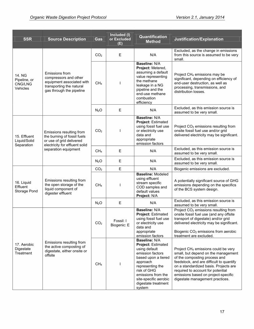
14. NG Pipeline, or CNG/LNG Vehicles
Emissions from compressors and other equipment associated with transporting the natural gas through the pipeline
CO2 E N/A Excluded, as the change in emissions from this source is assumed to be very small.
CH4 I
Baseline: N/A Project: Metered, assuming a default value representing the methane leakage in a NG pipeline and the end-use methane combustion efficiency
Project CH4 emissions may be significant, depending on efficiency of end-user destruction, as well as processing, transmissions, and distribution losses.
N2O E N/A Excluded, as this emission source is assumed to be very small.
15. Effluent Liquid/Solid Separation
Emissions resulting from the burning of fossil fuels or use of grid delivered electricity for effluent solid separation equipment
CO2 I
Baseline: N/A Project: Estimated using fossil fuel use or electricity use data and appropriate emission factors
Project CO2 emissions resulting from onsite fossil fuel use and/or grid delivered electricity may be significant.
CH4 E N/A Excluded, as this emission source is assumed to be very small.
N2O E N/A Excluded, as this emission source is assumed to be very small.
16. Liquid Effluent Storage Pond
Emissions resulting from the open storage of the liquid component of digester effluent
CO2 E N/A Biogenic emissions are excluded.
CH4 I
Baseline: Modeled using effluent stream specific COD samples and default values Project: N/A
A potentially significant source of GHG emissions depending on the specifics of the BCS system design.
N2O E N/A Excluded, as this emission source is assumed to be very small.
17. Aerobic Digestate Treatment
Emissions resulting from the active composting of digestate, either onsite or offsite
CO2 Fossil: I
Biogenic: E
Baseline: N/A Project: Estimated using fossil fuel use or electricity use data and appropriate emission factors
Project CO2 emissions resulting from onsite fossil fuel use (and any offsite transport of digestate) and/or grid delivered electricity may be significant. Biogenic CO2 emissions from aerobic treatment are excluded.
CH4 I
Baseline: N/A Project: Estimated using default emission factors based upon a tiered approach representing the risk of GHG emissions from the site-specific aerobic digestate treatment system
Project CH4 emissions could be very small, but depend on the management of the composting process and feedstock, and are difficult to quantify on a standardized basis. Projects are required to account for potential emissions based on project-specific digestate management practices.

Organic Waste Digestion Project Protocol Version 2.1, January 2014
18
SSR Source Description Gas Included (I) or Excluded
(E)
Quantification Method Justification/Explanation
N2O I
Baseline: N/A Project: Estimated using default emission factors based upon a tiered approach representing the risk of GHG emissions from the site-specific aerobic digestate treatment system
Project N2O emissions could be very small, but depend on the management of the composting process and feedstock, and are difficult to quantify on a standardized basis. Projects are required to account for potential emissions based on project-specific digestate management practices.
18. Anaerobic Digestate Disposal
Emissions from the anaerobic disposal of digestate
CO2 E N/A Biogenic emissions are excluded.
CH4 I
Baseline: N/A Project: Modeled w/ FOD model based on site-specific measurement of the quantity of digestate material disposed anaerobically, conservative default digestate characteristic factors, and local climate
If digestate is disposed of anaerobically, fugitive emissions under the project could be significant.
N2O E N/A Excluded, as this emission source is assumed to be very small.
19. Compost Transport
Fossil fuel emissions from the transport of the finished compost to the site of end-use
CO2 E N/A
Excluded because the difference in baseline and project case emissions is expected to be insignificant, In the absence of compost, other fertilizer products would be transported to the site of application.
CH4 E N/A Excluded, as this emission source is assumed to be very small.
N2O E N/A Excluded, as this emission source is assumed to be very small.
20. Electricity Grid
Fossil fuel emissions from electricity generation displaced by the project
CO2 E N/A This protocol does not cover displacement of GHG emissions from using biogas instead of fossil fuels in electrical generating equipment.
CH4 E N/A N2O E N/A
21. Use of Thermal Energy
Fossil fuel emissions from thermal energy generation displaced by the project
CO2 E N/A This protocol does not cover displacement of GHG emissions from using biogas instead of fossil fuels in thermal energy generating equipment.
CH4 E N/A N2O E N/A
22. Treated Wastewater Disposal or Discharge to WWTP
Emissions from treated agro-industrial wastewater disposed of, or discharged into, the natural environment or a sewer system
CO2 E N/A Excluded, as project activity is unlikely to increase emissions from wastewater disposal relative to baseline.
CH4 E N/A
N2O E N/A

Organic Waste Digestion Project Protocol Version 2.1, January 2014
19
SSR Source Description Gas Included (I) or Excluded
(E)
Quantification Method Justification/Explanation
23. Land Application
Emissions and Sinks related to the land application of treated manure, organic wastewater, and finished compost
CO2 E N/A
Excluded, as project activity is unlikely to increase emissions relative to baseline. Furthermore, the application of finished compost as soil amendment or mulch on agricultural lands can result in significant GHG benefits due to avoided fossil based fertilizer use, increased carbon sequestration, increased water retention in soils, and other impacts. This protocol does not address the GHG benefits of compost end-use, which is considered a complementary and separate activity.
CH4 E N/A
N2O E N/A

Organic Waste Digestion Project Protocol Version 2.1, January 2014
20
5 Quantifying GHG Emission Reductions GHG emission reductions from an OWD project are quantified by comparing actual project emissions to baseline emissions from anaerobic waste management of the eligible waste streams. Baseline emissions are an estimate of the GHG emissions from sources within the GHG Assessment Boundary (see Section 4) that would have occurred in the absence of the OWD project. Project emissions are actual GHG emissions that occur at sources within the GHG Assessment Boundary. Project emissions must be subtracted from the baseline emissions to quantify the project’s total net GHG emission reductions (Equation 5.1). GHG emission reductions must be quantified and verified at least every 12 months. Project developers may choose to quantify and verify GHG emission reductions on a more frequent basis if they desire. The length of time over which GHG emission reductions are quantified and verified is called the “reporting period.” The Reserve requires all projects to compare the calculated baseline emissions for the reporting period, as calculated in Section 5.1, to the ex-post metered quantity of methane that is destroyed in the biogas control system over the same period. The lesser of the two values must be used to estimate total baseline emissions for the reporting period. Equation 5.1 below provides the quantification approach that shall be used for calculating the emission reductions from OWD project activities. 21
21 The Reserve’s GHG reduction calculation method for OWD projects is derived from the Kyoto Protocol’s Clean Development Mechanism (AM0025 V.10, AM0073 V.1, ACM0014 V.2.1, AMS-III.E V.15.1, AMS-III.F V.6.0, and AMS-III.H V.9.0 ), and also draws from the Regional Greenhouse Gas Initiative (RGGI) Model Rule, the U.S. EPA Inventory of U.S. GHG Emissions and Sinks 1990-2006, and the 2006 IPCC Guidelines for National GHG Inventories
Organic Waste Digestion Project Protocol Version 2.1, January 2014
21
Figure 5.1. Organizational Chart of Equations in Section 5

Organic Waste Digestion Project Protocol Version 2.1, January 2014
22
Equation 5.1. Calculating GHG Emission Reductions
Where,
Units
ER = Total emission reductions for the reporting period tCO2e BE = Total baseline emissions for the reporting period, from all SSRs in
the GHG Assessment Boundary tCO2e
PE = Total project emissions for the reporting period, from all SSRs in the GHG Assessment Boundary (as calculated in Section 5.2)
tCO2e
( ) Where,
Units
BEc = Total calculated baseline emissions for the reporting period, from all SSRs in the GHG Assessment Boundary (as calculated in Section 5.1)
tCO2e
CH4,destroyed = Aggregated quantity of methane destroyed by the BCS during the reporting period (as calculated in Section 5.3)
tCO2e
5.1 Quantifying Baseline Emissions Total baseline emissions must be estimated by calculating and summing the expected baseline emissions for all relevant SSRs (as indicated in Table 4.1), during the reporting period. The calculations used to estimate baseline emissions will depend on the management option(s) that would have been used to treat and/or dispose of eligible organic waste streams in the absence of an OWD project. Different baseline management options are assumed depending on the type of eligible waste stream involved:
MSW Food Waste and Food-Soiled Paper Waste: Uneaten food, spoiled food, food preparation wastes, and non-recyclable food-soiled paper wastes from homes, restaurants, kitchens, grocery stores, campuses, cafeterias, and similar institutions is predominantly disposed of at managed landfills. Nation-wide, less than 3% of MSW food waste is currently diverted from landfills.22 Thus, for the purposes of this protocol, the baseline emissions from MSW food waste streams are calculated based on the assumption that the waste would have been disposed of at a landfill in the absence of the project.23 See Section 5.1.1 for the calculation procedure that must be used to quantify baseline emissions for eligible food and food-soiled paper waste streams.
Agro-industrial Wastewater: Organic loaded wastewater from industrial or agricultural
processing operations, if treated onsite at the facility, may be treated in uncontrolled anaerobic or semi-anaerobic lagoons, ponds, or tanks. Thus, for the purposes of this protocol, the baseline emissions from agro-industrial wastewater streams are calculated based on the wastewater treatment system in place prior to the installation of the BCS. The project developer must demonstrate that the pre-project wastewater treatment system utilized anaerobic treatment processes, and did not incorporate methane capture
22 U.S. EPA, Municipal Solid Waste Generation, Recycling, and Disposal in the United States – Tables and Figures for 2010. Table 2. 23 Food waste streams originating from grocery stores or supermarkets must have their pre-project disposal documented according to Section 6.1.2.

Organic Waste Digestion Project Protocol Version 2.1, January 2014
23
and control technologies. If this cannot be demonstrated for a particular wastewater stream, baseline emissions for the particular wastewater stream are assumed to be zero. See Section 5.1.2 for the calculation procedure that must be used to quantify baseline emissions for eligible wastewater streams.
Livestock manure: For projects that co-digest eligible organic waste streams together with livestock manure, the baseline emissions for manure management draw from the Reserve’s Livestock Project Protocol. Each livestock operation contributing manure waste to the digestion project shall account for baseline emissions from all sources within the GHG Assessment Boundary. See Section 5.1.3 of this protocol for requirements for calculating baseline emissions from manure management.
If the OWD project co-digests ineligible waste streams together with eligible organic waste streams, baseline emissions for all ineligible waste streams are assumed to be zero. As shown in Equation 5.2, baseline emissions equal:
The methane emissions from the decay of food and food-soiled paper waste deposited in a landfill (SSR 4), plus
The methane emissions from anaerobic wastewater treatment of agro-industrial wastewaters (SSR 6), plus
The methane generated by pre-project manure management systems (SSR 5) Equation 5.2. Total Calculated Baseline Methane Emissions
( ) Where,
Units
BEc = Total calculated baseline emissions from all SSRs in the GHG Assessment Boundary during the reporting period
tCO2e
BESW = Total baseline emissions during the reporting period, for eligible solid waste (food and food-soiled paper) streams (SSR 4)
tCO2e
BEWW = Total baseline emissions during the reporting period, for eligible agro-industrial wastewater streams (SSR 6)
tCO2e
BELS = Total sum of the calculated baseline emissions during the reporting period, for all livestock operations contributing manure to the digester (SSR 5)
tCO2e
5.1.1 Baseline Emissions from Eligible Food and Food-Soiled Paper Waste Streams (SSR 4)
Equations 5.3 and 5.4 represent the FOD model calculations that must be used to estimate baseline emissions for both the food waste component and the soiled paper component of the eligible waste that is digested by the project. For the calculation, the total weight of the food and soiled paper waste from each eligible waste stream must be aggregated over the reporting period. The inputs to the FOD model include:
The state waste-to-energy (WTE) rate – the percentage of the waste that would have gone to a waste incineration plant instead of a landfill on a state-by-state basis

Organic Waste Digestion Project Protocol Version 2.1, January 2014
24
The landfill gas collection efficiency (LCE) – the percentage of landfill gas that is captured and controlled due to the presence of a landfill gas collection and control system (see Box 5.1 for further information on the LCE parameter)
The waste-specific fraction of total degradable organic carbon (DOCS), and fraction of DOCS that is degradable under anaerobic conditions (DOCf)
The decay rate of the waste, k, which is a function of both the type of waste and external climate of the region where the waste would have been landfilled
The FOD model estimates the methane emissions that would have been emitted to the atmosphere over a period of ten years following the year in which the waste is diverted to the project’s BCS.24 Equation 5.3. Calculating Baseline Methane Emissions for Solid Waste Streams (SSR 4)
∑
Where,
Units
BESW = Total sum of the baseline emissions from solid waste (food waste and soiled paper waste) during the reporting period
tCO2e
BECH4,S = Baseline methane emissions from digested waste stream ‘S’ during the reporting period
tCO2e
Where,
Units
BEFW,S = Baseline methane emissions from the food waste component of eligible waste stream ‘S’ that is digested during the reporting period
tCO2e
BESP,S = Baseline methane emissions from the soiled paper component of eligible waste stream ‘S’ that is digested during the reporting period
tCO2e
24 The FOD model used in Equation 5.4 is referenced from the UNFCCC Clean Development Mechanism (CDM) approved methodology for calculating avoided methane emissions from waste diversion (CDM Annex 10 – Tool to determine methane emissions avoided from dumping waste at a SWDS (V4.0)). However, the model has been adapted in order to quantify emissions from a full ten years of waste degradation upfront rather than distributed on an annual basis. Due to modeling uncertainty, it is conservative to limit the calculation time frame to ten years, although waste would likely continue to break down in a landfill situation for much longer than ten years.

Organic Waste Digestion Project Protocol Version 2.1, January 2014
25
Equation 5.4. Baseline Methane Emissions from Eligible Food Waste, by Waste Stream
( )
Where,
Units
BEFW,S = Baseline methane emissions from the food waste component of eligible waste stream ‘S’ that is digested during the reporting period
tCO2e
0.9 = Model correction factor to account for model and waste composition uncertainties related to waste composition and waste characteristics25
fraction
WFW,S = Aggregated weight of eligible food waste (on a wet basis) from eligible waste stream ‘S’ that is digested by the project during the reporting period. See Section 5.1.1.1 for guidance on determining the weight of eligible food waste
t of food waste (wet
weight)
WTES = Fraction of waste from eligible waste stream ‘S’ that would have been incinerated at a waste-to-energy plant in lieu of being landfilled. This fraction is equal to the state-specific fraction of total generated waste that is incinerated. Referenced by waste origination state from Table B.2 in Appendix B
fraction
128 = Methane potential of food waste, measured on a wet basis26 m3CH4/t of food waste
(wet weight) ρ = Density of methane, equal to 0.000674 tCH4/m3 FEFW,S = Fraction of methane generated that is emitted to the atmosphere over a
ten year time horizon, as calculated using the First Order Decay function. The fraction emitted to the atmosphere is a function of the decay rates of food waste, the landfill gas collection assumptions (see Box 5.1), and the amount of methane generated that is oxidized in the cover soil
fraction
21 = Global warming potential of methane tCO2e / tCH4
25 As per CDM Annex 10 – Tool to determine methane emissions avoided from dumping waste at a SWDS (V4.0) http://cdm.unfccc.int/methodologies/PAmethodologies/tools/am-tool-04-v4.pdf/history_view 26 U.S. EPA Inventory of Greenhouse Gas Emissions and Sinks, 1990-2008. Annex 3, Ch. 3.14, pg. A-295.

Organic Waste Digestion Project Protocol Version 2.1, January 2014
26
Equation 5.4. (Continued)
∑[ ( ) ( ) ( ( ))]
( )
Where,
Units
e = Mathematical constant, approximately equal to 2.71828 kFW,S = Decay rate for food waste stream ‘S’. The decay rate is a function of the
climatological characteristics of the region where the waste is landfilled. Referenced from Table B.1 by waste type and climate category, which is referenced from Figure B.1
yr-1
x = Placeholder for the iterative calculation. The FOD equation calculates emissions out over a period of ten years (x=1 to 10) following the year in which the waste is initially diverted to the digester. The ten year calculation is summed and applied to the total baseline emissions for the current reporting period
GCS = Gas collection factor for waste stream ‘S’. The gas collection factor is equal to the fraction of waste disposed at landfills with gas collection systems in the state from which waste stream ‘S’ originates. Referenced by state from Table B.2 in Appendix B
fraction
LCEx = Fraction of methane that would be captured and destroyed by LFG collection systems in the year x, starting with the year that the waste is diverted to the project (x=1) and ending with year x=10. All projects shall use a value of 0.0 for the first two years of calculated waste decay (x=1 to 2), a value of 0.5 for the third year (x=3), a value of 0.75 for years 4 to 7 (x=4 to 7), and a value of 0.95 for the remaining years of decay until the end of the calculation period (x=8 to 10). See Box 5.1 for a discussion on LCE assumptions27
fraction
0.1 = Factor for the oxidation of methane by cover soil bacteria28 fraction
27 The Reserve will periodically re-assess the LCE default parameters in order to ensure that landfill gas collection assumptions remain conservative and accurate. 28 As per the Reserve Landfill Project Protocol V3.0, CDM Annex 10 – Tool to determine methane emissions avoided from dumping waste at a SWDS (V4.0), and U.S. EPA Solid Waste Management and Greenhouse Gases: A Lifecycle Assessment of Emissions and Sinks, Chapter 6, Pg. 87, ftnt27.

Organic Waste Digestion Project Protocol Version 2.1, January 2014
27
Equation 5.5. Baseline Methane Emissions from Eligible Soiled Paper Waste, by Waste Stream
( )
Where,
Units
BESP,S = Baseline methane emissions from the soiled paper component of eligible waste stream ‘S’ that is digested during the reporting period
tCO2e
WSP,S = Aggregated weight of eligible soiled paper waste (on a wet basis) from eligible waste stream ‘S’ that is digested by the project during the reporting period. See Section 5.1.1.1 for guidance on determining the weight of eligible soiled paper waste
t of soiled paper (wet
weight)
WTES = Fraction of waste from eligible waste stream ‘S’ that would have been incinerated at a waste-to-energy plant in lieu of being landfilled. This fraction is equal to the state-specific fraction of total generated waste that is incinerated. Referenced by waste origination state from Table B.2 in Appendix B
fraction
310 = Methane potential of soiled paper waste, measured on a wet basis. 29 m3CH4/t of food waste
(wet weight) ρ = Density of methane, equal to 0.000674 tCH4/m3 FESP,S = Fraction of methane generated that is emitted to the atmosphere over a
ten year time horizon, as calculated using the First Order Decay function. The fraction emitted to the atmosphere is a function of the decay rates of soiled paper waste, the landfill gas collection assumptions (see Box 5.1), and the amount of methane generated that is oxidized in the cover soil
fraction
21 = Global warming potential of methane tCO2e / tCH4
29 U.S. EPA Solid Waste Management and Greenhouse Gases: A Lifecycle Assessment of Emissions and Sinks, Chapter 6, Exhibit 6-3. The Value represents the methane potential of ‘office paper’.

Organic Waste Digestion Project Protocol Version 2.1, January 2014
28
Equation 5.5. (Continued)
∑[ ( ) ( ) ( ( ))] ( )
Where,
Units
e = Mathematical constant, approximately equal to 2.71828 kSP,S = Decay rate for soiled paper waste stream ‘S’. The decay rate is a
function of the climatological characteristics of the region where the waste is landfilled. Referenced from Table B.1 by waste type and climate category, which is referenced from Figure B.1
yr-1
GCS = Gas collection factor for waste stream ‘S’. The gas collection factor is equal to the fraction of waste disposed at landfills with gas collection systems in the state from which waste stream ‘S’ originates. Referenced by state from Table B.2 in Appendix B
fraction
LCEx = Fraction of methane that would be captured and destroyed by LFG collection systems in the year x, starting with the year that the waste is diverted to the project (x=1) and ending with year x=10. All projects shall use a value of 0.0 for the first two years of calculated waste decay (x=1 to 2), a value of 0.5 for the third year (x=3), a value of 0.75 for years 4 to 7 (x=4 to 7), and a value of 0.95 for the remaining years of decay until the end of the calculation period (x=8 to 10). See Box 5.1 for a discussion on LCE assumptions30
fraction
0.1 = Factor for the oxidation of methane by cover soil bacteria31 fraction
30 The Reserve will periodically re-assess the LCE default parameters in order to ensure that landfill gas collection assumptions remain conservative and accurate. 31 As per the Reserve Landfill Project Protocol V3.0, CDM Annex 10 – Tool to determine methane emissions avoided from dumping waste at a SWDS (V4.0), and U.S. EPA Solid Waste Management and Greenhouse Gases: A Lifecycle Assessment of Emissions and Sinks, Chapter 6, Pg. 87, ftnt27.
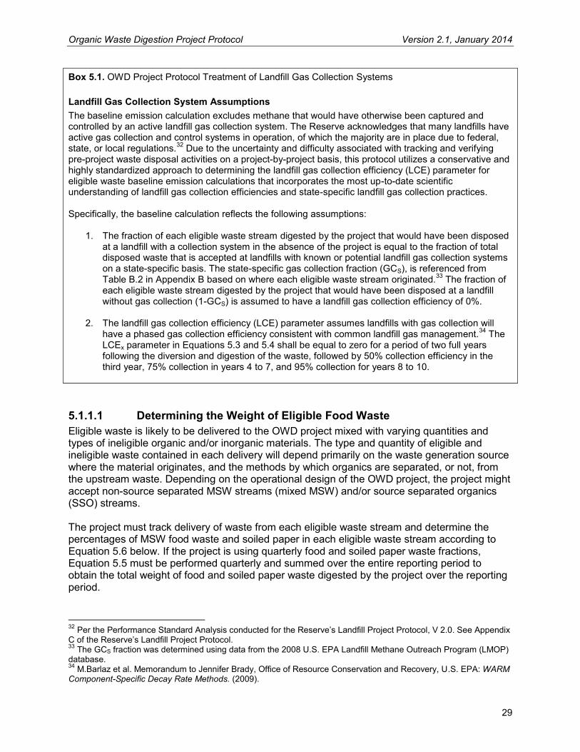
Organic Waste Digestion Project Protocol Version 2.1, January 2014
29
Box 5.1. OWD Project Protocol Treatment of Landfill Gas Collection Systems Landfill Gas Collection System Assumptions The baseline emission calculation excludes methane that would have otherwise been captured and controlled by an active landfill gas collection system. The Reserve acknowledges that many landfills have active gas collection and control systems in operation, of which the majority are in place due to federal, state, or local regulations.32 Due to the uncertainty and difficulty associated with tracking and verifying pre-project waste disposal activities on a project-by-project basis, this protocol utilizes a conservative and highly standardized approach to determining the landfill gas collection efficiency (LCE) parameter for eligible waste baseline emission calculations that incorporates the most up-to-date scientific understanding of landfill gas collection efficiencies and state-specific landfill gas collection practices. Specifically, the baseline calculation reflects the following assumptions:
1. The fraction of each eligible waste stream digested by the project that would have been disposed at a landfill with a collection system in the absence of the project is equal to the fraction of total disposed waste that is accepted at landfills with known or potential landfill gas collection systems on a state-specific basis. The state-specific gas collection fraction (GCS), is referenced from Table B.2 in Appendix B based on where each eligible waste stream originated.33 The fraction of each eligible waste stream digested by the project that would have been disposed at a landfill without gas collection (1-GCS) is assumed to have a landfill gas collection efficiency of 0%.
2. The landfill gas collection efficiency (LCE) parameter assumes landfills with gas collection will have a phased gas collection efficiency consistent with common landfill gas management.34 The LCEx parameter in Equations 5.3 and 5.4 shall be equal to zero for a period of two full years following the diversion and digestion of the waste, followed by 50% collection efficiency in the third year, 75% collection in years 4 to 7, and 95% collection for years 8 to 10.
5.1.1.1 Determining the Weight of Eligible Food Waste Eligible waste is likely to be delivered to the OWD project mixed with varying quantities and types of ineligible organic and/or inorganic materials. The type and quantity of eligible and ineligible waste contained in each delivery will depend primarily on the waste generation source where the material originates, and the methods by which organics are separated, or not, from the upstream waste. Depending on the operational design of the OWD project, the project might accept non-source separated MSW streams (mixed MSW) and/or source separated organics (SSO) streams. The project must track delivery of waste from each eligible waste stream and determine the percentages of MSW food waste and soiled paper in each eligible waste stream according to Equation 5.6 below. If the project is using quarterly food and soiled paper waste fractions, Equation 5.5 must be performed quarterly and summed over the entire reporting period to obtain the total weight of food and soiled paper waste digested by the project over the reporting period.
32 Per the Performance Standard Analysis conducted for the Reserve’s Landfill Project Protocol, V 2.0. See Appendix C of the Reserve’s Landfill Project Protocol. 33 The GCS fraction was determined using data from the 2008 U.S. EPA Landfill Methane Outreach Program (LMOP) database. 34 M.Barlaz et al. Memorandum to Jennifer Brady, Office of Resource Conservation and Recovery, U.S. EPA: WARM Component-Specific Decay Rate Methods. (2009).

Organic Waste Digestion Project Protocol Version 2.1, January 2014
30
Equation 5.6. Determining Weight of Eligible Food and Soiled Paper Waste
Where,
Units
WFW,S = Aggregated weight of eligible food waste (on a wet basis) from waste stream ‘S’ that is digested by the project during the reporting period
t food waste
WT,S = Aggregated total weight of waste (on a wet basis) from waste stream ‘S’ that is delivered to the facility during the reporting period
t
FDS = Fraction of waste stream ‘S’ that is digested during the reporting period fraction FFW,S = Food waste fraction of waste stream ‘S’. The fraction must be
determined based on the corresponding methods described in Sections 5.1.1.2 and 5.1.1.3 below, according to the type of waste delivered to the site
fraction
Where,
Units
WSP,S = Aggregated weight of eligible soiled paper waste (on a wet basis) from waste stream ‘S’ that is digested by the project during the reporting period
t soiled paper
FSP,S = Soiled paper waste fraction of waste stream ‘S’. The fraction must be determined based on the corresponding methods described in Sections 5.1.1.2 and 5.1.1.3 below, according to the type of waste delivered to the site
fraction
5.1.1.2 Determining the Fraction of Eligible Waste in a Mixed MSW Waste Stream (Non-Source Separated)
If a composting project is receiving a mixed MSW stream, the weight of food waste must be determined using one of the four options detailed below. The first two options are applicable for all mixed MSW waste streams, the third is applicable only to Materials Recovery Facility (MRF) fines, and the fourth is applicable only to non-SSO (i.e. mixed) organics-rich MSW from a single source facility. Option 1: The first option is to determine the weight of food waste using a national default factor of 20% of the total measured weight of the mixed MSW.35 Option 2: The second option is to determine the weight of food waste using a food waste composition factor based on a published state, regional, or municipal waste characterization study. If this option is chosen, the project must be sourcing a majority of the relevant waste stream from within the geographic boundaries of the study. The waste characterization study must have been conducted no more than 5 years prior to the current project reporting year.
35 Based on the EPA’s Municipal Solid Waste Generation, Recycling, and Disposal in the United States, Tables and Figures for 2010. Figure 13, pg. 45. (2011).

Organic Waste Digestion Project Protocol Version 2.1, January 2014
31
Option 3: The third option, applicable only to MRF fines, allows project developers to conduct site-specific waste sampling for the MSW fines composted at the operation according to the following procedure:
All sampling events shall use at least a 100 lb sample of the organic fine material that has recently passed through the final stage of the screening process
Material particles larger than approximately two inches in diameter shall be physically sorted or screened, and weighed. The remaining fines fraction shall be collected and weighed in its entirety. The remaining fines must be mixed and shoveled into a radially symmetrical pile, and divided into quarters using perpendicular boards. One quarter of the remaining fines must be collected and chosen for hand sampling, and used as a basis for the composition of all fines in that sample
The mixed waste quarter-sample shall be sorted into the following categories: food waste, soiled paper, other ineligible material
Each sampling event must quantify and record the proportional weight of food waste and of soiled paper as compared to the total weight of the sample:
To determine the characterization for the 100 lb (or greater) sample, the project developer must recombine the composition result analytically and determine the weighted average based on the relative amounts of fines, as well as the larger (greater than two inch) particles sampled. Using Equation 5.7, the project developer shall quantify the mean food waste proportional weight (FFW,S) and soiled paper proportional weight (FSP,S). The FFW,S and FSP,S values shall then be used in Equation 5.5 for MRF fines waste streams
Photo documentation and calculations must be recorded and retained for verification purposes, clearly showing the waste stream from which the sample is taken, the waste sample itself, the quartered sample pre-sorting, and the separated categories of waste following the hand-sorting
Each waste stream for which this procedure is applied shall have a minimum of eight sampling events (two per calendar quarter) for the first year that the stream is composted at the operation, followed by four sampling events every year thereafter (one per calendar quarter). The sampling events will produce single values for FFW,S and FSP,S for each calendar quarter. During a quarter with two sampling events, the values for that quarter shall be equal to an average of the respective values determined at each of the two events. Option 4: The fourth option is applicable only to organics-rich shipments of non-SSO (mixed) MSW that originate from a single source facility (either a single MRF or a single waste generator, such as a convention center or apartment complex). This option allows project developers to conduct site-specific waste sampling for the waste stream according to the following procedure:
A single load shall be divided into a grid of at least 8 cells, and then at least 4 of those cells shall be selected for sampling using a systematic, random sampling approach (e.g. construct a 4x2 grid and use a coin toss to select one cell from each pair). The particular cells to be sampled shall be chosen anew with each sampling event

Organic Waste Digestion Project Protocol Version 2.1, January 2014
32
All hand-sorting events shall use at least a 150 lb sample of the organic material from each cell that has been selected using the random sampling approach (i.e. at least four samples per event)
Each sample shall be sorted into the following categories: food waste, soiled paper, other ineligible material
Each sampling event must quantify and record the proportional weight of food waste and of soiled paper as compared to the total weight of the sample. The values for FFW,S and FSP,S shall be equal to the 90% lower confidence limit (LCL) of their respective sample results (Equation 5.7)
Photo documentation and calculations must be recorded and retained for verification purposes, clearly showing the waste stream from which the sample is taken, the grid used for sampling (where possible) and the waste contained in each cell of the grid, the sample pre-sorting, and the separated categories of waste following the hand sorting
Each waste stream for which this procedure is applied shall have a minimum of eight sampling events (two per calendar quarter) for the first year that the stream is composted at the operation, followed by four sampling events every year thereafter (one per calendar quarter). The sampling events will produce single values for FFW,S and FSP,S for each calendar quarter. Equation 5.7. Determining the Fraction of Eligible Waste in a Mixed-MSW MRF Fines Waste Stream
( ) ( )
Where,
Units
Fi,S = Fraction of waste category i (food waste or soiled paper waste) in eligible MRF fines waste stream ‘S’ (representing FFW,S for food waste and FSP,S for soiled paper waste)
fraction
WHS = Weight of sample taken in large (>2”) preliminary hand sort lbs Fi,HS = Fraction of waste category i in large (>2”) preliminary hand sort fraction WPR = Weight of total sample after large (>2”) particles removed lbs Fi,QS = Fraction of waste category i in quarter sample fraction Wsample = Weight of total sample prior to hand sort (100 lb minimum) (Note that
Wsample = WHS + WPR) lbs
5.1.1.3 Determining the Fraction of Eligible Waste in a Source Separated Organics (SSO) Waste Stream
SSO waste is generated by both the commercial and residential sectors. Residential food waste collection programs are likely to produce a waste stream that is a combination of yard waste, food waste, and soiled paper. In certain regions and/or seasons, residential SSO may have limited yard waste material and may be primarily food and soiled paper. Commercial sector waste generators are broken down further into separate categories (see Table 5.1). The types of commercial generators listed in Table 5.1 will primarily produce waste streams that consist of food waste and soiled paper in varying proportions.
5.1.1.3.1 Residential SSO Waste Stream Characterization In order to determine the percent of food and soiled paper waste in a residential SSO waste stream, projects must use local or site-specific waste characterization data to determine the

Organic Waste Digestion Project Protocol Version 2.1, January 2014
33
average fraction of food waste and soiled paper waste by weight collected by the residential diversion program. If available, projects may use local municipal waste characterization data provided by the local jurisdiction or a representative entity to quantify the proportion by weight of both food waste and soiled paper in the residential SSO waste stream. If local data are not available, projects must conduct site-specific waste sampling for each residential waste stream digested at the facility in accordance with the requirements in Section 5.1.1.4.
5.1.1.3.2 Commercial SSO Waste Stream Characterization Commercial SSO waste is primarily food and food-soiled paper waste (excluding corrugated cardboard, which would be an ineligible waste type). By volume, commercial waste streams would likely contain a high proportion of soiled paper wastes to food waste, however on a weight basis it would be expected that the paper component of the waste stream would constitute a much smaller proportion due to the fact that food waste is very high in moisture, whereas paper material would be much less dense with a much lower moisture content. If an SSO collection route delivers eligible SSO waste to the project that is collected from multiple commercial facilities across different categories, then the proportional weight of food waste and soiled paper waste in the mixed commercial SSO stream must be determined by conducting site-specific waste characterization in accordance with the requirements in Section 5.1.1.4. If a commercial SSO waste stream is delivered to the facility from a single facility, or an exclusive aggregate of facilities within the same category (e.g. a collection route servicing restaurants only), the project may apply the default factors rather than site-specific waste characterization.36 The default values must be applied to the weight of the waste stream following initial removal of contaminants and/or ineligible SSO material (e.g. corrugated cardboard boxes). Table 5.1. Waste Generator Categories and Default Food and Soiled Paper Fractions by Weight
Waste Generator Category Fraction of Food Waste by Weight
Fraction of Soiled Paper by Weight
Restaurants/Cafeterias/Dining Halls/Other Food Service 0.80 0.10 Super Markets and Grocery Stores 0.80 0.10 Food Wholesale Distributors 0.70 0.20 Special Events and Public Venues 0.60 0.30 Other Commercial (Hotels, Office Buildings, Wholesale Distributors) 0.50 0.40
5.1.1.4 Site-Specific Waste Characterization Procedure All site-specific waste characterization of SSO waste streams shall be done according to the following requirements37:
Each waste stream shall have a minimum of 2 sampling runs per quarter, with each run consisting of at least 4 separate samples, for a total of 8 waste characterization samples per quarter
36 Default values are developed by determining the ratio of Misc. Paper and Composite Paper to Food Waste generated within each waste generator category. Each category assumes 10% ineligible feedstock by weight as a conservativeness factor. The composition data is taken from California’s Targeted Statewide Waste Characterization Study: Waste Disposal and Diversion Findings for Selected Industry (Cascadia Consulting Group), 2006. The data is specific to California, however the types and proportions of material generated within a category would be expected to be relatively independent of region. 37 It is recommended, but not required, that the waste characterization be performed by a qualified third party service provider.

Organic Waste Digestion Project Protocol Version 2.1, January 2014
34
All waste characterization samples shall be at least 100 lb weight (wet) of mixed material drawn from a recent delivery of the SSO stream in question prior to mixing with other waste streams
Each waste sample shall be sorted into the following categories: food waste, soiled paper, other ineligible material
For each sample, the project developer must quantify and record the proportional weight of food waste and of soiled paper as compared to the total weight of the sample
The project must quantify the food waste proportional weight and soiled paper proportional weight (FFW,S and FSP,s) on a quarterly basis by using Equation 5.8 below to determine the 1-sided lower 90% confidence bound based on the 8 recorded proportional weight results
Written records and photo documentation must be retained for verification purposes. Section 6.1.1.1 provides requirements for site-specific waste characterization photo documentation and record keeping. For commercial SSO waste streams delivered to the project from a single facility, the site-specific waste characterization events may occur on site or at the commercial waste generation facility. Equation 5.8. Determining the Quarterly Fractional Weight of Food and Soiled Paper Waste
(
√ )
Where,
Units
FFW,S and FSP,S
= Quarterly fractional weight of food and soiled paper waste (respectively) from waste stream ‘S’, equal to the 1-sided 90% lower confidence bound of the 8 quarterly fractional weights
fraction
mean = Quarterly fractional weight sample mean (of food or soiled paper waste) based on the number of sampling events
fraction
tvalue = 1-sided 90% t-value coefficient for a dataset with degrees of freedom df38
fraction
SD = Standard deviation of the quarterly fractional weight (of food or soiled paper waste)
fraction
n = Sample size df = Degrees of freedom (= n-1)
5.1.2 Baseline Emissions from Eligible Agro-Industrial Wastewater Streams (SSR 6)
The calculations to determine the baseline methane emissions from agro-industrial wastewater streams that otherwise would have been treated in an anaerobic pond, lagoon, or tank are presented in Equation 5.9 and Equation 5.10 below. These equations shall be used to calculate the baseline emissions for each eligible wastewater stream that is digested in the project’s BCS for each reporting period. Baseline emissions will be zero for any wastewater streams that, in
38 For Microsoft Excel 2007 and earlier versions, use the formula “=TINV(0.2,df)”. For version 2010 and later, use the formula “=T.INV.2T(0.2,df)”.

Organic Waste Digestion Project Protocol Version 2.1, January 2014
35
the absence of the project, would have been treated at a wastewater treatment plant that collects and combusts methane gas. The following equations calculate methane emissions that would have occurred during the reporting period from anaerobic decomposition of the waste in an anaerobic storage/treatment lagoon, pond, or tank by utilizing waste-specific inputs. The waste specific inputs include:
The chemical cxygen demand (COD) of the wastewater as sampled – representing the organic load of the wastewater
The methane conversion factor (MCF) – a function of the baseline storage/treatment system
The methane producing capacity of the wastewater (B0) – a function of the type of wastewater
Equation 5.9 and Equation 5.10 present the calculations that shall be used to quantify baseline emissions from all eligible wastewater streams during the reporting period. Each wastewater stream ‘S’ shall be sampled for COD content monthly according the guidance provided in Section 6.1.3.1. Equation 5.9. Total Baseline Emissions for Eligible Agro-Industrial Wastewater Streams (SSR 6)
∑
Where,
Units
BEWW = Total sum of the baseline emissions from each eligible wastewater stream entering the digester during the reporting period
tCO2e
BECH4,WW,S = Baseline methane emissions from wastewater stream ‘S’, for the reporting period, calculated per Equation 5.10
tCO2e

Organic Waste Digestion Project Protocol Version 2.1, January 2014
36
Equation 5.10. Baseline Emissions for Each Eligible Wastewater Stream
∑( )
Where,
Units
BECH4,WW,S = Baseline methane emissions from wastewater stream ‘S’, for the reporting period
tCO2e
B0,WW,S = Methane producing capacity of the wastewater stream ‘S’. Project developers may use site-specific values that are determined based on the sampling approach provided in Section 6.1.3.2. The wastewater stream must be sampled prior to mixing with other residues. Alternatively, a conservative default value of 0.21 may be used39
tCH4 / tCOD
MCFAT,S = Methane conversion factor of the anaerobic treatment lagoon, pond, or tank where the waste was treated pre- project, equal to the lower bound value for the treatment system as provided in Table B.5 in Appendix B
fraction
21 = Global warming potential for methane tCO2e/tCH4
0.89
= Baseline uncertainty factor to account for model uncertainties40 fraction
QWW,S,i = Volume of wastewater from stream ‘S’ in month i m3 CODWW,S,i = Chemical oxygen demand of the untreated wastewater stream ‘S’ for
month i. COD must be sampled prior to mixing with other residues, and must be sampled according to the guidance in Section 6.1.3.1 for each wastewater stream ‘S’ on a monthly basis
tCOD/m3
5.1.3 Baseline Emissions from Manure Treatment Systems (SSR 5) For projects that are co-digesting manure alongside eligible organic waste streams, project developers calculate the baseline emissions for the reporting period from all manure waste streams according to the pre-project manure management system in place at the livestock operation from which the manure is sourced. All livestock operations contributing waste to the digester must calculate baseline emissions from all manure management systems in accordance with the Reserve Livestock Project Protocol’s baseline calculation approach (using the version of the Livestock Project Protocol that is current at the time of project submittal41). Projects co-digesting manure, whose reporting periods begin or end with incomplete calendar months, shall only quantify the baseline and project emissions for the portion of the month that is included within the reporting period. If a project developer can demonstrate that a particular manure management system is not affected by the project activity, then this system can be excluded from the baseline and project calculations. Baseline emissions from all livestock operations must be aggregated per Equation 5.11 below.
39 Per CDM ACM0014 V.2.1 and CDM AMS III.F V.6 40 Per Clean Development Mechanism (CDM) Methodology III.H, V.16. 41 If a newer version of the Livestock Project Protocol is adopted subsequent to the project submittal, project developers have the option to upgrade to the newer version. However, reverting to a previous version is not allowed.

Organic Waste Digestion Project Protocol Version 2.1, January 2014
37
Equation 5.11. Baseline Emissions for Eligible Manure Streams (SSR 5)
∑
Where,
Units
BELS = Total sum of the calculated baseline emissions during the reporting period, for all livestock operations contributing manure to the digester (SSR 5)
tCO2e
BECH4,LS,S = Baseline methane emissions from all affected manure management systems ‘S’, for the reporting period, calculated per the Livestock Project Protocol
tCO2e
5.2 Quantifying Project Emissions Project emissions are actual GHG emissions that occur within the GHG Assessment Boundary as a result of project activity. Project emissions must be quantified every reporting period on an ex-post basis. As shown in Equation 5.12, project emissions equal:
The carbon dioxide emissions from mobile and stationary combustion of fossil fuels and/or the use of grid delivered electricity (SSRs 3, 8, 13, 15, 17), plus
The amount of methane created by the biogas control system that is not captured and destroyed by the control system (SSRs 9, 10, 11, 12, 14), plus
The methane generated by the digester effluent storage pond (SSR 16), plus The methane and nitrous oxide produced by the aerobic treatment of the residual
digestate produced in the digestion process (SSR 17), plus The methane generated by the anaerobic disposal of the residual digestate produced in
the digestion process (SSR 18), plus The methane created by manure treatment and storage systems that were affected by
project activity (SSR 5)
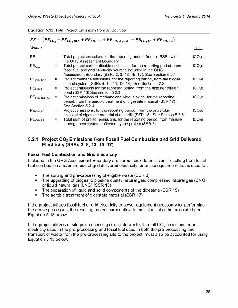
Organic Waste Digestion Project Protocol Version 2.1, January 2014
38
Equation 5.12. Total Project Emissions from All Sources
( )
Where,
Units
PE = Total project emissions for the reporting period, from all SSRs within the GHG Assessment Boundary
tCO2e
PECO2 = Total project carbon dioxide emissions, for the reporting period, from fossil fuel and grid electricity sources included in the GHG Assessment Boundary (SSRs 3, 8, 13, 15, 17). See Section 5.2.1
tCO2e
PECH4,BCS = Project methane emissions, for the reporting period, from the biogas control system (SSRs 9, 10, 11, 12, 14). See Section 5.2.2
tCO2e
PECH4,EF = Project emissions for the reporting period, from the digester effluent pond (SSR 16) See section 5.2.3
tCO2e
PECH4,N2O,AT = Project emissions of methane and nitrous oxide, for the reporting period, from the aerobic treatment of digestate material (SSR 17). See Section 5.2.4
tCO2e
PECH4,LF = Project emissions, for the reporting period, from the anaerobic disposal of digestate material at a landfill (SSR 18). See Section 5.2.5
tCO2e
PECH4,LS = Total sum of project emissions, for the reporting period, from manure management systems affected by the project (SSR 5)
tCO2e
5.2.1 Project CO2 Emissions from Fossil Fuel Combustion and Grid Delivered Electricity (SSRs 3, 8, 13, 15, 17)
Fossil Fuel Combustion and Grid Electricity Included in the GHG Assessment Boundary are carbon dioxide emissions resulting from fossil fuel combustion and/or the use of grid delivered electricity for onsite equipment that is used for:
The sorting and pre-processing of eligible waste (SSR 8) The upgrading of biogas to pipeline quality natural gas, compressed natural gas (CNG)
or liquid natural gas (LNG) (SSR 13) The separation of liquid and solid components of the digestate (SSR 15) The aerobic treatment of digestate material (SSR 17)
If the project utilizes fossil fuel or grid electricity to power equipment necessary for performing the above processes, the resulting project carbon dioxide emissions shall be calculated per Equation 5.13 below. If the project utilizes offsite pre-processing of eligible waste, then all CO2 emissions from electricity used in the pre-processing and fossil fuel used in both the pre-processing and transport of waste from the pre-processing site to the project, must also be accounted for using Equation 5.13 below.

Organic Waste Digestion Project Protocol Version 2.1, January 2014
39
Equation 5.13. Project Carbon Dioxide Emissions from Fossil Fuel and Grid Electricity
( )
Where,
Units
PECO2 = Total project carbon dioxide emissions, for the reporting period, from fossil fuel and grid electricity sources included in the GHG Assessment Boundary (SSRs 3, 8, 13, 15, 17)
tCO2e
PECO2,FF = Total carbon dioxide emissions from the destruction of fossil fuel during the reporting period
tCO2
PECO2,EL = Total indirect carbon dioxide emissions from the consumption of electricity from the grid during the reporting period
tCO2
∑ ( )
Where,
Units
FFPR,i = Total fossil fuel consumed by onsite combustion during the reporting period, by fuel type i
volume fossil fuel
EFFF,i = Fuel-specific emission factor, reference from Appendix B kgCO2 / volume fossil fuel
1000 = Kilograms per tonne kgCO2/tCO2
( )
Where,
Units
ELPR = Total electricity from the grid consumed by project operations over the reporting period
MWh
EFEL = Carbon emission factor for electricity used, referenced from the most recent U.S. EPA eGRID emission factor publication. Projects shall use the annual total output emission rates for the subregion where the project is located
tCO2/MWh
5.2.2 Project Emissions from the Biogas Control System (SSRs 9, 10, 11, 12, 14) The biogas control system (consisting of the digester, the gas collection system, and the destruction devices) may be a significant source of methane emissions due to leakage of biogas from the digester and collection system (SSR 9) and incomplete destruction of methane in the various destruction devices (SSRs 10, 11, 12, 14). Methane emissions from the biogas control system must be calculated using Equation 5.14 below, using continuous biogas flow measurements and monthly methane concentration measurements. All flow measurement devices should internally correct to standard temperature and pressure (60°F and 1 atm). If the biogas flow metering equipment does not internally correct for temperature and pressure, both temperature and pressure must be measured continuously and the guidance provided in Equation 5.15 shall be used to adjust the flow for temperature and pressure.
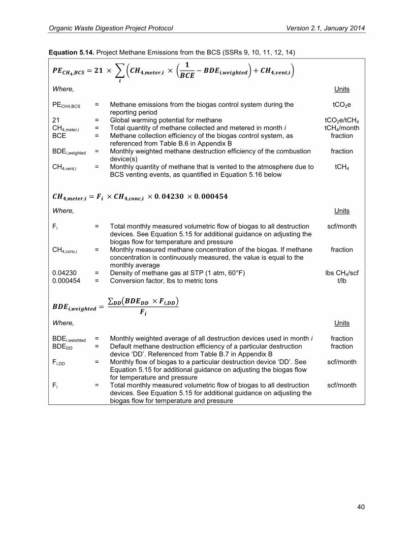
Organic Waste Digestion Project Protocol Version 2.1, January 2014
40
Equation 5.14. Project Methane Emissions from the BCS (SSRs 9, 10, 11, 12, 14)
∑( (
) )
Where,
Units
PECH4,BCS = Methane emissions from the biogas control system during the reporting period
tCO2e
21 = Global warming potential for methane tCO2e/tCH4 CH4,meter,i = Total quantity of methane collected and metered in month i tCH4/month BCE = Methane collection efficiency of the biogas control system, as
referenced from Table B.6 in Appendix B fraction
BDEi,weighted = Monthly weighted methane destruction efficiency of the combustion device(s)
fraction
CH4,vent,i = Monthly quantity of methane that is vented to the atmosphere due to BCS venting events, as quantified in Equation 5.16 below
tCH4
Where,
Units
Fi = Total monthly measured volumetric flow of biogas to all destruction devices. See Equation 5.15 for additional guidance on adjusting the biogas flow for temperature and pressure
scf/month
CH4,conc,i = Monthly measured methane concentration of the biogas. If methane concentration is continuously measured, the value is equal to the monthly average
fraction
0.04230 = Density of methane gas at STP (1 atm, 60°F) lbs CH4/scf 0.000454 = Conversion factor, lbs to metric tons t/lb
∑ ( )
Where,
Units
BDEi,weighted = Monthly weighted average of all destruction devices used in month i fraction BDEDD = Default methane destruction efficiency of a particular destruction
device ‘DD’. Referenced from Table B.7 in Appendix B fraction
Fi,DD = Monthly flow of biogas to a particular destruction device ‘DD’. See Equation 5.15 for additional guidance on adjusting the biogas flow for temperature and pressure
scf/month
Fi = Total monthly measured volumetric flow of biogas to all destruction devices. See Equation 5.15 for additional guidance on adjusting the biogas flow for temperature and pressure
scf/month
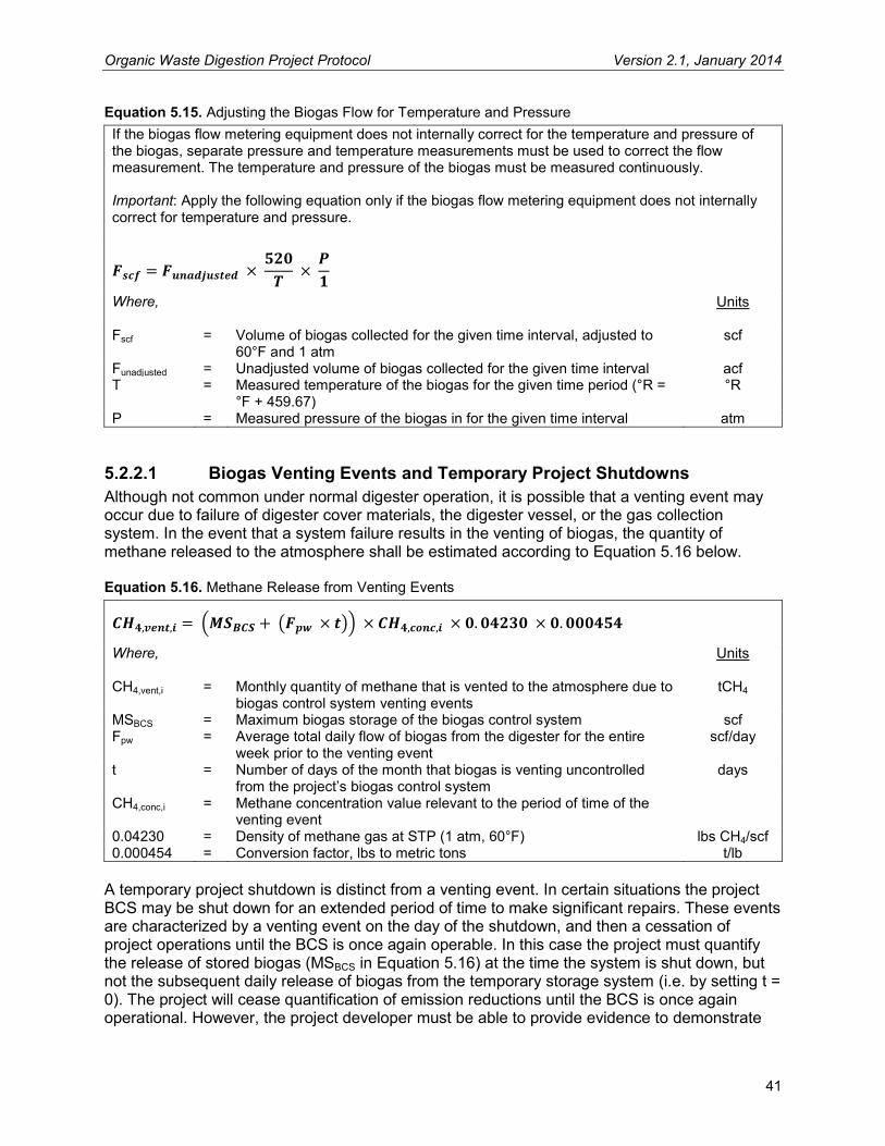
Organic Waste Digestion Project Protocol Version 2.1, January 2014
41
Equation 5.15. Adjusting the Biogas Flow for Temperature and Pressure If the biogas flow metering equipment does not internally correct for the temperature and pressure of the biogas, separate pressure and temperature measurements must be used to correct the flow measurement. The temperature and pressure of the biogas must be measured continuously. Important: Apply the following equation only if the biogas flow metering equipment does not internally correct for temperature and pressure.
Where,
Units
Fscf = Volume of biogas collected for the given time interval, adjusted to 60°F and 1 atm
scf
Funadjusted = Unadjusted volume of biogas collected for the given time interval acf T = Measured temperature of the biogas for the given time period (°R =
°F + 459.67) °R
P = Measured pressure of the biogas in for the given time interval atm
5.2.2.1 Biogas Venting Events and Temporary Project Shutdowns Although not common under normal digester operation, it is possible that a venting event may occur due to failure of digester cover materials, the digester vessel, or the gas collection system. In the event that a system failure results in the venting of biogas, the quantity of methane released to the atmosphere shall be estimated according to Equation 5.16 below. Equation 5.16. Methane Release from Venting Events
( ( ))
Where,
Units
CH4,vent,i = Monthly quantity of methane that is vented to the atmosphere due to biogas control system venting events
tCH4
MSBCS = Maximum biogas storage of the biogas control system scf Fpw = Average total daily flow of biogas from the digester for the entire
week prior to the venting event scf/day
t = Number of days of the month that biogas is venting uncontrolled from the project’s biogas control system
days
CH4,conc,i = Methane concentration value relevant to the period of time of the venting event
0.04230 = Density of methane gas at STP (1 atm, 60°F) lbs CH4/scf 0.000454 = Conversion factor, lbs to metric tons t/lb
A temporary project shutdown is distinct from a venting event. In certain situations the project BCS may be shut down for an extended period of time to make significant repairs. These events are characterized by a venting event on the day of the shutdown, and then a cessation of project operations until the BCS is once again operable. In this case the project must quantify the release of stored biogas (MSBCS in Equation 5.16) at the time the system is shut down, but not the subsequent daily release of biogas from the temporary storage system (i.e. by setting t = 0). The project will cease quantification of emission reductions until the BCS is once again operational. However, the project developer must be able to provide evidence to demonstrate

Organic Waste Digestion Project Protocol Version 2.1, January 2014
42
that project emissions did not exceed baseline emissions for this period. This is achieved by demonstrating that the management of waste during the shutdown is either the same as the baseline scenario for that waste stream (i.e. unheated lagoon for wastewater and manure or landfill for food waste) or is aerobic.
5.2.3 Project Methane Emissions from Liquid Digester Effluent Storage and Treatment (SSR 16)
Methane emissions from liquid digester effluent storage must be calculated using Equation 5.17 below. All projects sending the liquid portion of digester effluent to a storage pond shall use the following calculation approach to quantify project emissions from the effluent storage pond. If an OWD project recycles digester effluent, disposes of the effluent directly to a sewage system, or otherwise manages the effluent without the use of a liquid effluent storage pond, then this emission source is not applicable to the project. Because of the variable nature of the waste entering the digester, it is necessary to base calculations on quarterly COD measurements taken from the effluent exiting the digester prior to entering the effluent storage pond. See Section 6.1.3.1 for additional guidance on performing COD sampling. Equation 5.17. Project Methane Emissions from the BCS Effluent Pond (SSR 16)
∑( )
Where,
Units
PECH4,EF = Total project methane emissions from the biogas control system effluent pond over the reporting period
tCO2e
B0,EF = Methane producing capacity of the effluent stream ‘S’. Project developers may use site-specific values that are determined based on the sampling approach provided in Section 6.1.3.2. Alternatively, a value of 0.21 may be used for all effluent42
tCH4 / tCOD
0.3 = Methane conversion factor of the effluent storage pond43 fraction 21 = Global warming potential for methane tCO2e/tCH4 1.12 = Project uncertainty factor to account for model uncertainties44
QEF,i = Volume of effluent discharged into the effluent storage pond in month i
m3
CODEF,i = Chemical oxygen demand of the effluent discharged into the storage pond in month i. COD must be sampled quarterly according to the guidance provided in Section 6.1.3.1
tCOD/m3
5.2.4 Project Emissions from Aerobic Treatment of Digestate (SSR 17) The digestion of organic waste may produce residual waste (digestate) that, depending on how it is treated, could result in material emissions of methane and/or nitrous oxide. The degree to which aerobic treatment of organics releases methane and/or nitrous oxide to the atmosphere is highly uncertain due the complicated GHG emission pathways for methane and nitrous oxide, given various aerobic treatment methods. On a project-by-project basis, it is difficult to quantify 42 Per CDM ACM0014 V.2.1 and CDM AMS III.F V.6. 43 Equal to the higher bound MCF value for the anaerobic shallow lagoon system. 2006 IPCC Guidelines for National GHG Inventories, Vol. 5 Ch. 6 Table 6.3. 44 Per CDM AMS III.H, V.16.

Organic Waste Digestion Project Protocol Version 2.1, January 2014
43
the emissions of methane and nitrous oxide that occur from the composting of digestate material, however it is possible to place bounds on the emissions based on peer reviewed literature and internationally accepted GHG accounting methodologies.45 For the purposes of this protocol, a conservative approach is taken based on a range of possible emission factors and a range of potential composting techniques that either maximize or minimize the potential for GHG emissions. Table 5.2 outlines the tiered approach that must be followed to estimate the combined emissions of methane and nitrous oxide as a function of the amount of digestate going into the composting process (measured on a wet basis).46 The emission factors in Table 5.2 are applicable whether the digestate is treated at the project site or, in the case of centralized digesters, is returned to the source farms to be treated. If digestate is transported offsite for disposal, the CO2 emissions related to transport fuels should be accounted for using Equation 5.13. Table 5.2. Combined Methane and Nitrous Oxide Emission Factors for Aerobic Treatment of Digestate
Tier (GHG Emission Risk Level)
CH4 and N2O Emission Factor
(tCO2e / t (wet weight) of digestate aerobically treated*)
High: Digestate treated onsite in uncovered non-aerated static piles Material treated offsite at an undocumented facility
0.10
Medium: Digestate treated onsite in aerated systems (turned windrows
or aerated static piles) Material treated offsite at a centralized composting facility
0.06
Low: Digestate treated onsite in an enclosed system (in-vessel)
utilizing a bio-filter or biogas scrubber 0.02
Zero: Materials thermally dried upon separation from liquid effluent Materials used directly as animal bedding material Digestate immediately blended as soil amendment
0
* Project developers may use the site-specific weight of waste going to aerobic treatment, or may use a conservative default value equal to 20% of the wet weight of the waste entering the digester. 47 OWD projects shall use Equation 5.18 to estimate the combined emissions of methane and nitrous oxide from aerobic digestate treatment, using the appropriate emission factor from Table 5.2 above.
45 Bounds for potential emissions of N2O and CH4 were developed based upon estimates and empirical results of GHG emission from composting, taken from the following sources: 2006 IPCC Guidelines for National GHG Inventories, CDM AM0025 V10, U.S. EPA Solid Waste Management and Greenhouse Gases: A Life-Cycle Assessment of Emissions and Sinks (2006), and Brown et al. Greenhouse Gas Balance for Composting Operations (2008). 46 The GHG risk level is assessed based off of information obtained from: Brown et al. Greenhouse Gas Balance for Composting Operations (2008) 47 Default weight based conservatively on expert feedback

Organic Waste Digestion Project Protocol Version 2.1, January 2014
44
Equation 5.18. Methane and Nitrous Oxide Emissions from Aerobic Treatment of Digestate (SSR 17)
Where,
Units
PECH4,N2O,AT = Project emissions of methane and nitrous oxide, for the reporting period, from the aerobic treatment of digestate material
tCO2e
WD,AT = Total wet weight of digestate treated aerobically onsite, or sent offsite for aerobic treatment, over the reporting period. Project proponents may use site specific weights, or may use a default value of 20% of the wet weight of waste entering the digester
t
EFD,AT = Emission factor for the appropriate aerobic treatment Tier, as provided in Table 5.2
tCO2e / t digestate
Project carbon dioxide emissions from the use of fossil fuel or grid powered equipment during the aerobic digestate treatment process are calculated in Section 5.2.1.
5.2.5 Project Emissions from Anaerobic Disposal of Digestate Produced in the Digestion Process (SSR 18)
If residual waste (digestate) is disposed of anaerobically, all such waste will be treated as if it had been landfilled, and the resulting methane emissions will be accounted for using Equation 5.19. In order to quantify the emissions from the landfilling of digestate, the project developer must track the weight of digestate that is treated anaerobically during the reporting period (WD,LF). Project developers should use the look-up table (Table B.1 in Appendix B) to find the appropriate emission factor for the project. Equation 5.19. Methane Emissions from Anaerobic Treatment of Digestate (SSR 18)
Where,
Units
PECH4,LF = Project emissions, for the reporting period, from the anaerobic disposal of digestate material at a landfill
tCO2e
WD,LF = Total wet weight of digestate treated anaerobically over the reporting period. Project proponents must monitor the weight of digestate being treated anaerobically according to guidance in Section 6.1.4.2
t
EFLF = Emission factor for the appropriate climate region, as provided in Table B.4
tCO2e / t digestate
5.2.6 Project Emissions from Manure Treatment Systems (SSR 5) For projects that are co-digesting manure alongside eligible organic waste streams, it is necessary to account for the project emissions from all manure management systems that have been affected by project activity. This is necessary per the GHG accounting method used in the Reserve Livestock Project Protocol.48 If the baseline anaerobic system still receives a percentage of the manure stream on an ongoing basis, the emissions from this source could be
48 The Reserve Livestock Project Protocol sums the entire methane emissions from the baseline anaerobic lagoon, assuming that all the manure sent to the baseline anaerobic lagoon pre-project is sent to the BCS in the project scenario, however if a project is sending less than 100% of the manure stream to the BCS, then the remaining portion that is still going to the anaerobic lagoon after project implementation must be accounted for as project emissions.

Organic Waste Digestion Project Protocol Version 2.1, January 2014
45
significant. If a project developer can demonstrate that a particular manure management system has not been affected by project activity, then this system can be excluded from the project emissions calculation. The project emissions calculation must be performed in accordance with the Reserve Livestock Project Protocol’s project emissions guidance for non-BCS related sources, and aggregated for each livestock operation according to Equation 5.20 below. Equation 5.20. Project Emissions from Non-BCS Related Manure Treatment/Storage Systems
∑
Where,
Units
PECH4,LS = Total sum for the reporting period of the project methane emission calculation results for all manure management systems affected by project activity
tCO2e
PECH4,LS,S = Project methane emissions from manure management system ‘S’ for the reporting period, as calculated per the method described in the non-BCS project emissions section of the Livestock Project Protocol
tCO2e
5.3 Calculating the Total Quantity of Methane Destroyed by the Project
The Reserve recognizes that there can be material differences between the calculated emission reductions and the actual quantity of methane that is captured and destroyed by the biogas control system. In most cases, the amount of metered methane that is destroyed by the project in any given reporting period should greatly exceed the sum of the baseline emissions over the same time period, due primarily to the incomplete degradation of waste as modeled in the FOD equation over a 10 year timeframe. In some instances, however, digester performance issues related to start-up periods, venting events, and other biogas control system operational issues may result in sub-optimal gas generation or destruction. These operational issues have the potential to result in substantially less methane destruction than is calculated, leading to an overestimation of emission reductions. To address this issue and maintain consistency with international best practice, the Reserve requires that calculated baseline emissions be compared to the ex-post metered quantity of methane that is captured and destroyed by the biogas control system. The lesser of the two values will represent the total baseline emissions for the reporting period.
Projects shall use Equation 5.21 to determine the total quantity of methane that is captured and destroyed by the project’s BCS.

Organic Waste Digestion Project Protocol Version 2.1, January 2014
46
Equation 5.21. Metered Methane Destruction
∑( )
Where,
Units
CH4,destroyed = Aggregated quantity of methane collected and destroyed during the reporting period
tCO2e
CH4,meter,i = Monthly quantity of methane collected and metered. See Equation 5.14 for calculation guidance
tCH4/month
BDEi = Monthly methane destruction efficiency of the combustion device. In the event that there is more than one destruction device in operation in any given month, the weighted average destruction efficiency from all combustion devices is to be used
fraction
21 = Global warming potential for methane tCO2e/tCH4

Organic Waste Digestion Project Protocol Version 2.1, January 2014
47
6 Project Monitoring The Reserve requires a Monitoring Plan to be established for all monitoring and reporting activities associated with the project. The Monitoring Plan will serve as the basis for verifiers to confirm that the monitoring and reporting requirements in this section and Section 7 have been and will continue to be met, and that consistent, rigorous monitoring and record-keeping is ongoing at the project site. The Monitoring Plan must cover all aspects of monitoring and reporting contained in this protocol and must specify how data for all relevant parameters in Table 6.1 (below) will be collected and recorded. At a minimum the Monitoring Plan shall stipulate the frequency of data acquisition; a record keeping plan (see Section 7.2 for minimum record keeping requirements); the frequency of instrument cleaning, inspection, field check and calibration activities; and the role of individuals performing each specific monitoring activity, as well as QA/QC provisions to ensure that data acquisition and meter calibration are carried out consistently and with precision. The Monitoring Plan shall also contain a detailed project diagram – beginning when waste arrives at the project site – including the placement of all meters and equipment that affect SSRs within the GHG Assessment Boundary (see Figure 4.1). Finally, the Monitoring Plan must include procedures that the project developer will follow to ascertain and demonstrate that the project at all times passes the Legal Requirement Test (Section 3.5.2). Project developers are responsible for monitoring the performance of the project and ensuring that the operation of all project-related equipment is consistent with the manufacturer’s recommendations.
6.1 Organic Waste and Wastewater Monitoring Requirements There are numerous parameters related to OWD project activities that must be monitored and tracked in order to accurately quantify the baseline and project emissions. Below are the requirements that shall be met for the monitoring of OWD projects.
6.1.1 Food and Food-Soiled Paper Waste Monitoring In order to quantify the GHG reductions from an OWD project that is digesting food and food-soiled paper waste streams, the project must accurately measure the quantity of in-coming waste delivered to the digestion facility, by waste stream. All projects must monitor and record each shipment of waste delivered to the facility using onsite scales and/or commercial receipts. The facility must keep a daily log showing:
Date and time of all deliveries of material to the facility The weight of each delivered in-coming waste stream The source of each delivered in-coming waste stream
In addition, the project must retain all weigh scale receipts generated either onsite or offsite indicating the weight and source of all delivered material to the facility. This information is necessary to aggregate the weight of eligible food and food-soiled paper waste delivered to the site from each eligible waste stream according to the guidance provided in Section 5.1.1 and to verify eligibility of MSW food waste from grocery store sources.

Organic Waste Digestion Project Protocol Version 2.1, January 2014
48
A QA/QC procedure for the inspection and calibration of weigh scales must be included in the Monitoring Plan. All weigh scales that are not used for commercial activities must be inspected and calibrated in accordance with manufacturer’s specifications. The project may document in-coming waste weight using commercial receipts from onsite or offsite scales.
6.1.1.1 Documenting Site-Specific Waste Characterization Events For each site-specific waste characterization event performed, the following records and photo documentation must be retained in order to demonstrate compliance with the waste characterization requirements of Section 5.1.1.4. The following data must be recorded and retained for each sampling event:
Origination and description of the waste stream each sample is drawn from Empty weight for each container used in the waste sort Weight of each sample (subtracting container weight) for the pre-sort sample and post-
sort waste components (food, paper, ineligible waste) Fractional weight of each component (food, paper, ineligible waste) as compared to the
total weight of the original sample
Photo documentation must be recorded and retained for verification purposes. Photo documentation should clearly show:
The weigh scale or scales used for the sampling event The containers used for the sampling event The waste stream from which the sample was taken The waste sample prior to sorting The separated categories post-sorting
6.1.2 Monitoring and Documenting Pre-Project Waste Disposal for Grocery Store Waste Streams
Source-separated waste streams originating from grocery stores or supermarkets are eligible if, and only if, the project developer can document that:
For a continuous period of at least 36 months prior to the date that waste sourced from the grocery store was first digested at the project digester, food and food-soiled paper waste generated by the grocery store was sent to a landfill, or
Food and/or food-soiled paper waste originating from the grocery store was deemed as eligible waste at an OWC or OWD project registered with the Reserve, or
The grocery store from which the waste originated is a new facility In order to document the eligibility of the grocery store waste stream, projects must monitor the following information for each grocery store waste stream:
The initial date the waste stream is delivered to the project digester, for all new grocery store waste streams
The origin of the new grocery store waste stream (by facility) The previous waste disposal methods used by the grocery store waste generator, for
each new grocery store waste stream The opening date of any new grocery store facilities supplying waste to the project

Organic Waste Digestion Project Protocol Version 2.1, January 2014
49
Additionally, documentation demonstrating that grocery store waste was sent to landfill(s) prior to diversion to the project digester or that the grocery store is a new facility should be collected and retained by the project for verification purposes. Acceptable documentation includes, but is not limited to:
Landfill tipping receipts from the grocery store and/or contracted waste haulers Waste hauler contracts Internal memos and/or employee training documents detailing waste handling and/or
organics separation procedures, goals, and timelines Media or marketing campaigns detailing dates related to the grocery store waste
diversion program Internal documentation, store leasing documents, or media or marketing campaigns
announcing the opening date of the grocery store facility
6.1.3 Agro-Industrial Wastewater Monitoring For OWD projects that pump eligible agro-industrial wastewater streams into the digester, the project developer shall monitor and record the following data for each wastewater stream:
The daily volume of wastewater (m3/day) entering the digester (aggregated monthly) The monthly COD of the wastewater (tCOD/m3) prior to mixing with other residues
The monthly COD of the wastewater must be determined by sampling. All COD sampling must be performed in accordance with the requirements in Section 6.1.3.1. A QA/QC procedure for the inspection, cleaning, and calibration of wastewater monitoring equipment must be included in the Monitoring Plan. Wastewater monitoring instruments must be inspected, cleaned, and calibrated in accordance with manufacturer’s specifications.
6.1.3.1 Requirements for Chemical Oxygen Demand Sampling The chemical oxygen demand (COD) must be sampled and analyzed in accordance with the COD sampling and analysis technique detailed in the Standard Methods for the Examination of Water and Wastewater, 5220 – Chemical Oxygen Demand.49 COD sampling and analysis shall be done by professionals experienced with the procedures used to determine COD as described in the above mentioned Standard Method approach.
6.1.3.2 Requirements for Determining the Site-Specific Maximum Methane Potential (B0)
For OWD projects that choose to determine a site-specific maximum methane potential value for one or more wastewater streams being digested in the project’s BCS, the following criteria must be met in order to ensure accuracy and consistency of the site-specific B0 values:
1. Wastewater samples for each eligible wastewater stream must be sampled prior to mixing with other residues.
2. For each eligible wastewater stream, a total of at least ten samples must be taken across the span of at least 1 week.
3. All samples must be analyzed using a Biochemical Methane Potential (BMP) Assay procedure at an independent, third-party laboratory that is familiar and experienced with
49 http://www.standardmethods.org/store/ProductView.cfm?ProductID=37
Organic Waste Digestion Project Protocol Version 2.1, January 2014
50
this test and ISO 11734.50 The laboratory must be able to document at least three years of experience with the BMP assay, and must have procedures in place to maintain a consistent inoculum. The laboratory must maintain and follow a standard operating procedure that outlines the process used in undertaking BMP analysis at that laboratory, and which can be made available to a verifier upon request.
4. At least ten samples must be analyzed by the chosen laboratory, the highest and lowest outlier results shall be discarded, and the site-specific B0 value to be used for the sampled wastewater stream shall equal the 90% lower confidence limit of the remaining assay results. The laboratory shall conduct an assay on the seed inoculum itself in order to control for its contribution to the methane potential of the wastewater samples. The laboratory shall also conduct a control assay with a substrate of known methane potential (such as glucose or cellulose) to verify correct procedures were followed and that the inoculum was viable. If the control assay differs from its established expected value by greater than 15%, all results from that batch of assays shall be discarded. Measurement of gas flow shall be corrected to standard temperature and pressure (60°F and 1 atm). Devices used to measure gas flow and methane content shall be properly installed and calibrated, such that they can provide results within +/- 5% accuracy.
A site-specific B0 value determined according to the requirements outlined above will be valid for the reporting period during which the sampling occurred. The verifier must confirm that sampling procedures conform to this section and that the personnel responsible for the sampling are trained and competent.
6.1.4 Digester Effluent and Digestate Monitoring
6.1.4.1 Liquid Effluent For OWD projects that send the liquid portion of the digester effluent to a temporary storage pond, the project developer is responsible for monitoring the effluent that is discharged from the digester in order to quantify the methane emissions from the effluent storage pond for the reporting period in accordance with Equation 5.17. This requires that the project developer directly monitor and record:
The daily volume of digester effluent wastewater (m3/day) that is exiting the digester prior to entering the effluent storage pond (aggregated monthly)
The quarterly COD (tCOD/m3) of the effluent wastewater exiting the digester prior to entering the effluent storage pond
As an alternative to measuring the daily volume of digester effluent exiting the digester, the project developer may use the total daily measured influent volume of wastewater that enters the digester as a conservative approximation for daily digester effluent volume. The quarterly COD of the effluent must be determined by sampling. All COD sampling must be performed in accordance with the requirements in Section 6.1.3.1. Samples must be taken prior to effluent entering the storage pond, and must be taken after solids are removed from the effluent stream.
50 For more information on BMP Assay analysis and procedures, see: Moody et al. “Use of Biochemical Methane Potential (BMP) Assays for Predicting and Enhancing Anaerobic Digester Performance.” (2009) http://sa.pfos.hr/sa2009/radovi/pdf/Radovi/r10-009.pdf

Organic Waste Digestion Project Protocol Version 2.1, January 2014
51
A QA/QC procedure for the inspection, cleaning, and calibration of wastewater monitoring equipment must be included in the Monitoring Plan. Effluent monitoring instruments shall be inspected, cleaned, and calibrated in accordance with manufacturer’s specifications.
6.1.4.2 Digestate Material For OWD projects that dispose of all or a portion of the project’s digestate material at a landfill or using some other anaerobic treatment method, the project developer is responsible for monitoring the quantity of digestate that is disposed of in such manner. Emissions from the anaerobic disposal of digestate must be quantified in accordance with Section 5.2.5. This requires that the project developer directly monitor and record all vehicles delivering digestate to landfill systems or other anaerobic treatment locations/systems and record:
The weight (metric tons) on a wet basis of digestate material that is disposed of using such a method (aggregated for the reporting period)
6.2 Biogas Control System Monitoring Project developers are responsible for monitoring the performance of the project and for operating each component of the BCS in a manner consistent with the manufacturer’s recommendations. The methane capture and control system must be monitored with measurement equipment that directly meters:
The flow of biogas delivered to each destruction device (except as specified below), measured continuously and recorded every 15 minutes or totalized and recorded at least daily, adjusted for temperature and pressure
The fraction of methane in the biogas, measured no less than once for every three month period (i.e. a 12 month reporting period should contain no less than 4 methane concentration measurements)
A single flow meter may be used to monitor the flow of gas to multiple destruction devices under certain conditions. If all destruction devices are of identical methane destruction efficiency (as described in Table B.7) and verified to be operational during all times when flow is recorded (i.e. there is recorded evidence of destruction), no additional steps are necessary for project registration. One example of this scenario would be a single meter used for a bank of multiple, identical engines that are always operated together. If the destruction devices are not of identical efficiency, then the destruction efficiency of the least efficient device shall be applied to the flow data for this meter. If there are any periods where the operational data show that one or more devices were not destroying methane, these periods are eligible for crediting, provided that the verifier can confirm all of the following conditions are met:
a. The destruction efficiency of the least efficient destruction device in operation is used as the destruction efficiency for all destruction devices monitored by this meter; and
b. All devices are either equipped with valves on the input gas line that close automatically if the device becomes non-operational (requiring no manual intervention), or designed in such a manner that it is physically impossible for gas to pass through while the device is non-operational; and
c. For any period where one or more destruction device(s) within this arrangement is not operational, it is documented that the remaining operational devices have the capacity to destroy the maximum gas flow recorded during the period. For devices other than flares, it is shown that the output corresponds to the flow of gas.

Organic Waste Digestion Project Protocol Version 2.1, January 2014
52
Flow data must be corrected for temperature and pressure at 60°F and 1 atm, either internally or by using Equation 5.15. Figure 6.1 represents the suggested arrangement of the biogas flow meters and methane concentration metering equipment. It is recommended that some level of gas conditioning occurs prior to the measurement of flow and methane concentration to prevent measurement error due to moisture and contaminant buildup.
Figure 6.1. Suggested Arrangement of Biogas Metering Equipment Note: The number of flow meters must be sufficient to track the total flow as well as the flow to each combustion device. The above example includes one more flow meter than would be necessary to achieve this objective. Operational activity of the destruction devices shall be monitored and documented at least hourly to ensure actual methane destruction. GHG reductions will not be accounted for or credited during periods in which the destruction device is not operational. For flares, operation is defined as thermocouple readings above 500°F. For all other destruction devices, the means of demonstration shall be determined by the project developer and subject to verifier review. An exception to this requirement is made for destruction devices that receive less than 10% of the total biogas generated during the reporting period and that can be demonstrated to comply with condition (b) in the list above (in this Section). Those devices do not need to be monitored for operational status. If for any reason the destruction device or the operational monitoring equipment (for example, the thermocouple on the flare) is inoperable, then all metered biogas going to the particular device shall be assumed to be released to atmosphere during the period of inoperability. In other words, for periods of missing “on/off” operational data, a value of “off” shall be used. During the period of inoperability, the destruction efficiency of the device must be assumed to be zero. In Equation 5.14, the monthly destruction efficiency (BDE) value shall be adjusted accordingly. See below for an example BDE adjustment.

Organic Waste Digestion Project Protocol Version 2.1, January 2014
53
Box 6.1. Example BDE Adjustment As an example, consider a situation where the primary destruction device is an open flare with a BDE of 96%, and it is found to be inoperable for a period of 5 days of a 30 day month. Assume that the total flow of biogas to the flare for the month is 3,000,000 scf, and that the total flow recorded for the 5 day period of inoperability is 500,000 scf. In this case, the monthly BDE would be adjusted as follows: BDE = {(0.96 x 2,500,000) + (0.0 x 500,000)} / 3,000,000 = 80%
6.2.1 Biogas Measurement Instrument QA/QC All gas flow meters51 must be:
Cleaned and inspected according to a regular schedule as documented in the project’s Monitoring Plan. Project developers and verifiers should consult with the manufacturer and installer of the metering equipment to determine the proper cleaning procedure and frequency to ensure that accuracy remains within the acceptable tolerance
Field checked for calibration accuracy with the percent drift documented, using either a portable instrument (such as a pitot tube) or manufacturer specified guidance, at the end of but no more than two months prior to or after the end date of the reporting period52
Calibrated by the manufacturer or a certified calibration service per manufacturer’s guidance or every 5 years, whichever is more frequent
All continuous methane analyzers must be:
Cleaned and inspected according to a regular schedule as documented in the project’s Monitoring Plan. Project developers and verifiers should consult with the manufacturer and installer of the equipment to determine the proper cleaning procedure and frequency to ensure that accuracy remains within the acceptable tolerance
Field checked for calibration accuracy with the percent drift documented, using either a portable instrument (such as a portable methane analyzer) or manufacturer specified guidance, at the end of but no more than two months prior to or after the end date of the reporting period.53 A field check procedure should be sufficient to confirm accuracy of the methane analyzer as it is installed, under typical site conditions (temperature, pressure, flow rate) and prior to any cleaning and inspection
Calibrated by the manufacturer or a certified calibration service per manufacturer’s guidance or every 5 years, whichever is more frequent
Alternative for regulated meters:
Projects that export biogas through a pipeline may have installed a custody transfer meter – or similar commercial measurement device – for the measurement and analysis
51 Field checks and calibrations of flow meters shall assess the volumetric output of the flow meter. 52 Instead of performing field checks, the project developer may instead have equipment calibrated by the manufacturer or a certified calibration service per manufacturer’s guidance, at the end of but no more than two months prior to the end date of the reporting period to meet this requirement. 53 Instead of performing field checks, the project developer may instead have equipment calibrated by the manufacturer or a certified calibration service per manufacturer’s guidance, at the end of but no more than two months prior to or after the end date of the reporting period to meet this requirement.

Organic Waste Digestion Project Protocol Version 2.1, January 2014
54
of biogas delivered to the pipeline. If the accuracy of this meter, and the maintenance and calibration necessary to maintain accuracy, are regulated by a government agency (including specific requirements for maintenance, inspection, and/or calibration), then the project may prove adherence to those regulatory requirements in lieu of the QA/QC requirements listed above. The standard of accuracy must be at least +/- 5%.
If the required calibration or calibration check is not performed and properly documented, no GHG credits may be generated for that reporting period. Flow meter calibrations shall be documented to show that the meter was calibrated to a range of flow rates consistent with the range of expected flow rates produced by the project BCS. Methane analyzer calibrations shall be documented to show that the calibration was carried out to the range of conditions (temperature and pressure) corresponding to the range of conditions that occur in the project BCS. If the field check on a piece of equipment reveals accuracy outside of a +/- 5% threshold, calibration by the manufacturer or a certified service provider is required for that piece of equipment. However, if the field check indicates that the measurement accuracy of the meter has drifted, the project developer has the option to first record the as-found condition (percent drift) of the field check, then clean the equipment and conduct a second field check. If this second check indicates measurement accuracy within the acceptable threshold, no further calibration is required and the as-left condition of the meter shall be recorded to document calibration accuracy. This shall be considered a failed field check followed by a successful field check. If the second field check confirms accuracy outside of the +/- 5% threshold, calibration by the manufacturer or a certified service provider is required for that piece of equipment. For the interval between the last successful field check and any calibration event confirming accuracy outside of the +/- 5% threshold, all data from that meter or analyzer must be scaled according to the following procedure. These adjustments must be made for the entire period from the last successful field check until such time that the meter is shown to be measuring within the accuracy threshold (unless the last event occurred during the prior reporting period, in which case adjustment is made back to the beginning of the current reporting period).
For calibrations or field checks that indicate the flow meter was outside the +/- 5% accuracy threshold, the project developer shall estimate total emission reductions using i) the metered values without correction, and ii) the metered values adjusted based on the greatest calibration drift recorded at the time of calibration. The lower of the two emission reduction estimates shall be reported as the scaled emission reduction estimate
For example, if a project conducts field checks quarterly during a year-long reporting period, then only three months of data will be subject at any one time to the penalties above. However, if the project developer feels confident that the meter does not require field checks or calibration on a greater than annual basis, then failed events will accordingly require the penalty to be applied to the entire year’s data. Further, frequent calibration may minimize the total accrued drift (by zeroing out any error identified), and result in smaller overall deductions. In order to provide flexibility in verification, data monitored up to two months after a field check may be verified for the reporting period. As such, the end date of the reporting period must be no more than two months after the latest successful field check.

Organic Waste Digestion Project Protocol Version 2.1, January 2014
55
If a portable calibration instrument is used (such as a pitot tube), the portable instrument shall be calibrated at least annually by the manufacturer or at an ISO 17025 accredited laboratory. The portable instrument also must be field calibrated to a known sample gas prior to each use.
6.2.2 Missing Data In situations where the flow rate or methane concentration monitoring equipment is missing data, the project developer shall apply the data substitution methodology provided in Appendix D.
6.3 Monitoring Parameters Prescribed monitoring parameters necessary to calculate baseline and project emissions are provided in Table 6.1. Refer to the monitoring section of the Livestock Project Protocol for the prescribed monitoring parameters necessary for livestock manure baseline and project calculations.
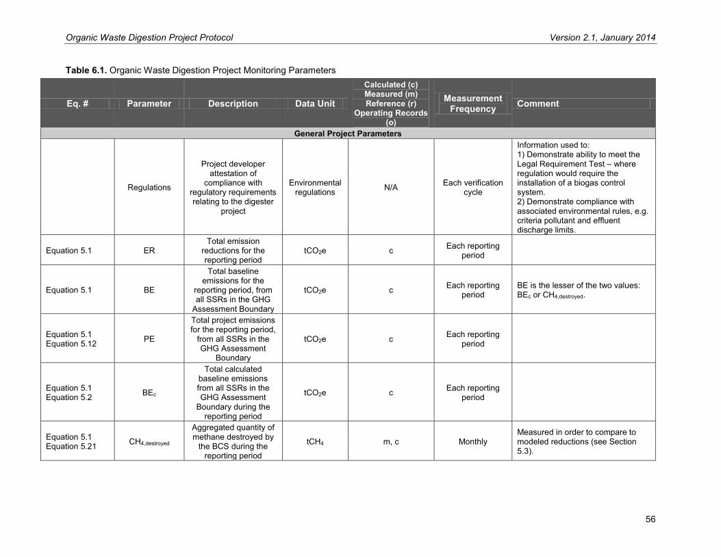
Organic Waste Digestion Project Protocol Version 2.1, January 2014
56
Table 6.1. Organic Waste Digestion Project Monitoring Parameters
Eq. # Parameter Description Data Unit
Calculated (c) Measured (m) Reference (r)
Operating Records (o)
Measurement Frequency Comment
General Project Parameters
Regulations
Project developer attestation of
compliance with regulatory requirements relating to the digester
project
Environmental regulations N/A Each verification
cycle
Information used to: 1) Demonstrate ability to meet the Legal Requirement Test – where regulation would require the installation of a biogas control system. 2) Demonstrate compliance with associated environmental rules, e.g. criteria pollutant and effluent discharge limits.
Equation 5.1 ER Total emission
reductions for the reporting period
tCO2e c Each reporting period
Equation 5.1 BE
Total baseline emissions for the
reporting period, from all SSRs in the GHG
Assessment Boundary
tCO2e c Each reporting period
BE is the lesser of the two values: BEc or CH4,destroyed.
Equation 5.1 Equation 5.12 PE
Total project emissions for the reporting period,
from all SSRs in the GHG Assessment
Boundary
tCO2e c Each reporting period
Equation 5.1 Equation 5.2 BEc
Total calculated baseline emissions from all SSRs in the GHG Assessment
Boundary during the reporting period
tCO2e c Each reporting period
Equation 5.1 Equation 5.21 CH4,destroyed
Aggregated quantity of methane destroyed by
the BCS during the reporting period
tCH4 m, c Monthly Measured in order to compare to modeled reductions (see Section 5.3).

Organic Waste Digestion Project Protocol Version 2.1, January 2014
57
Eq. # Parameter Description Data Unit
Calculated (c) Measured (m) Reference (r)
Operating Records (o)
Measurement Frequency Comment
Equation 5.2 Equation 5.3 BESW
Total baseline emissions during the reporting period, for eligible solid waste
(food and food-soiled paper) streams
tCO2e c Each reporting period
Equation 5.2 Equation 5.9 BEWW
Total baseline emissions during the reporting period, for
eligible agro-industrial wastewater streams
tCO2e c Each reporting period
Equation 5.2 Equation 5.11 BELS
Total sum of the calculated baseline
emissions during the reporting period, for all
livestock operations contributing manure to
the digester
tCO2e c Each reporting period
Baseline Calculation Parameters for Food and Food-Soiled Paper Waste Streams
Origin of waste streams
The jurisdiction where the food waste and/or
soiled paper waste originates
Jurisdiction (municipality
or county) N/A For each
truckload of waste
This information is necessary to track eligible food waste streams and ineligible food waste streams that are digested in the project’s BCS, as well as to determine appropriate decay rates (k values) to use in the calculation.
Equation 5.3 BECH4,S
Baseline methane emissions from
digested waste stream ‘S’ during the reporting
period
tCO2e c Each reporting period
Equation 5.3 Equation 5.4 BEFW,S
Baseline methane emissions from the food
waste component of eligible waste stream
‘S’ that is digested during the reporting
period
tCO2e c Each reporting period

Organic Waste Digestion Project Protocol Version 2.1, January 2014
58
Eq. # Parameter Description Data Unit
Calculated (c) Measured (m) Reference (r)
Operating Records (o)
Measurement Frequency Comment
Equation 5.3 Equation 5.5 BESP,S
Baseline methane emissions from the
soiled paper component of eligible waste stream
‘S’ that is digested during the reporting
period
tCO2e c Each reporting period
Equation 5.4 Equation 5.6 WFW,S
Aggregated weight of eligible food waste (on
a wet basis) from eligible waste stream ‘S’ that is digested by the project during the
reporting period
t of food waste (wet weight) c Each reporting
period
Equation 5.4 Equation 5.5 WTES
Fraction of waste from eligible waste stream ‘S’ that would have
been incinerated at a waste-to-energy (WTE)
plant in lieu of being landfilled
Fraction r N/A Referenced by state of origination.
Equation 5.4 FEFW,S
Fraction of methane generated that is
emitted to the atmosphere over a ten year time horizon, as calculated using the First Order Decay
function
Fraction c Each reporting period
The fraction emitted to the atmosphere is a function of the decay rates of food waste, the landfill gas collection assumptions (see Box 5.1), and the amount of methane generated that is oxidized in the cover soil.
Equation 5.4 kFW,S
Decay rate for food waste stream ‘S’, by
waste type and climate region
yr-1 r N/A
Referenced from Table B.1 in Appendix B. Figure B.1 is used to determine the climate region. The appropriate k value shall be chosen based on the k value applicable to the county where the waste originated.
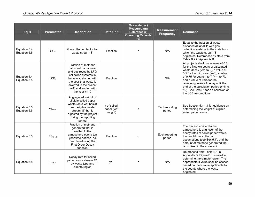
Organic Waste Digestion Project Protocol Version 2.1, January 2014
59
Eq. # Parameter Description Data Unit
Calculated (c) Measured (m) Reference (r)
Operating Records (o)
Measurement Frequency Comment
Equation 5.4 Equation 5.5 GCS Gas collection factor for
waste stream ‘S’ Fraction r N/A
Equal to the fraction of waste disposed at landfills with gas collection systems in the state from which the waste stream ‘S’ originates. Referenced by state from Table B.2 in Appendix B.
Equation 5.4 Equation 5.5 LCEx
Fraction of methane that would be captured and destroyed by LFG collection systems in
the year x, starting with the year that waste is diverted to the project (x=1) and ending with
the year x=10
Fraction r N/A
All projects shall use a value of 0.0 for the first two years of calculated waste decay (x=1 to 2), a value of 0.5 for the third year (x=3), a value of 0.75 for years 4 to 7 (x=4 to 7), and a value of 0.95 for the remaining years of decay until the end of the calculation period (x=8 to 10). See Box 5.1 for a discussion on the LCE assumptions.
Equation 5.5 Equation 5.6 WSP,S
Aggregated weight of eligible soiled paper
waste (on a wet basis) from eligible waste stream ‘S’ that is
digested by the project during the reporting
period
t of soiled paper (wet
weight) c Each reporting
period
See Section 5.1.1.1 for guidance on determining the weight of eligible soiled paper waste.
Equation 5.5 FESP,S
Fraction of methane generated that is
emitted to the atmosphere over a ten year time horizon, as calculated using the First Order Decay
function
Fraction c Each reporting period
The fraction emitted to the atmosphere is a function of the decay rates of soiled paper waste, the landfill gas collection assumptions (see Box 5.1), and the amount of methane generated that is oxidized in the cover soil.
Equation 5.5 kSP,S
Decay rate for soiled paper waste stream ‘S’,
by waste type and climate region
yr-1 r N/A
Referenced from Table B.1 in Appendix B. Figure B.1 is used to determine the climate region. The appropriate k value shall be chosen based on the k value applicable to the county where the waste originated.

Organic Waste Digestion Project Protocol Version 2.1, January 2014
60
Eq. # Parameter Description Data Unit
Calculated (c) Measured (m) Reference (r)
Operating Records (o)
Measurement Frequency Comment
Equation 5.6 WT,S
Aggregated total weight of waste (on a wet basis) from waste stream ‘S’ that is
delivered to the facility during the reporting
period
t m Every delivery of waste stream ‘S’
to the facility
Measured using onsite or offsite weigh scales. All weigh receipts must be retained for verification and deliveries must be logged daily.
Equation 5.6 FDS
Fraction of waste stream ‘S’ that is
digested during the reporting period
Fraction o N/A
In the instance that less than 100% of a delivered waste stream is digested at the facility (e.g. if a portion of the waste is composted across the street at a neighboring compost facility). Equal to 1 if all eligible waste delivered is digested.
Equation 5.6 Equation 5.8 FFW,S Food waste fraction of
waste stream ‘S’ Fraction m, r
Quarterly (if measured) or
once during the reporting period (if
referenced)
The fraction must be determined based on the corresponding methods described in Sections 5.1.1.2 and 5.1.1.3 according to the type of waste delivered to the site and the availability of local or state waste characterization data.
Equation 5.6 Equation 5.8 FSP,S
Soiled paper waste fraction of waste stream
‘S’ Fraction m, r
Quarterly (if measured) or
once during the reporting period (if
referenced)
The fraction must be determined based on the corresponding methods described in Sections 5.1.1.2 and 5.1.1.3 according to the type of waste delivered to the site and the availability of local or state waste characterization data.
Equation 5.7 Fi,S
Fraction of waste category i (food waste or soiled paper waste) in eligible MRF fines
waste stream ‘S’
Fraction m, c
Twice per quarter for the first year that the waste
stream is composted by the
project and quarterly thereafter
The fraction of waste category i must be determined for each waste stream ‘S’. The fraction is determined according to Section 5.1.1.2. Represents FFW,S for food waste and FSP,S for soiled paper waste.
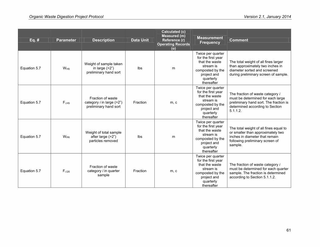
Organic Waste Digestion Project Protocol Version 2.1, January 2014
61
Eq. # Parameter Description Data Unit
Calculated (c) Measured (m) Reference (r)
Operating Records (o)
Measurement Frequency Comment
Equation 5.7 WHS Weight of sample taken
in large (>2”) preliminary hand sort
lbs m
Twice per quarter for the first year that the waste
stream is composted by the
project and quarterly thereafter
The total weight of all fines larger than approximately two inches in diameter sorted and screened during preliminary screen of sample.
Equation 5.7 Fi,HS Fraction of waste
category i in large (>2”) preliminary hand sort
Fraction m, c
Twice per quarter for the first year that the waste
stream is composted by the
project and quarterly thereafter
The fraction of waste category i must be determined for each large preliminary hand sort. The fraction is determined according to Section 5.1.1.2.
Equation 5.7 WPR Weight of total sample
after large (>2”) particles removed
lbs m
Twice per quarter for the first year that the waste
stream is composted by the
project and quarterly thereafter
The total weight of all fines equal to or smaller than approximately two inches in diameter that remain following preliminary screen of sample.
Equation 5.7 Fi,QS Fraction of waste
category i in quarter sample
Fraction m, c
Twice per quarter for the first year that the waste
stream is composted by the
project and quarterly thereafter
The fraction of waste category i must be determined for each quarter sample. The fraction is determined according to Section 5.1.1.2.

Organic Waste Digestion Project Protocol Version 2.1, January 2014
62
Eq. # Parameter Description Data Unit
Calculated (c) Measured (m) Reference (r)
Operating Records (o)
Measurement Frequency Comment
Equation 5.7 Wsample Weight of total sample prior to hand sort (100
lb minimum) lbs m
Twice per quarter for the first year that the waste
stream is composted by the
project and quarterly thereafter
Wsample = WHS + WPR
Baseline Calculation Parameters for Agro-Industrial Wastewater Streams
Equation 5.9 Equation 5.10 BECH4,WW,S
Baseline methane emissions from
wastewater stream ‘S’, for the reporting period
tCO2e c Each reporting period
Equation 5.10 B0,WW,S Methane producing
capacity of the wastewater stream ‘S’
tCH4/tCOD m, r Once per reporting period
A site-specific value may be used; alternatively, a value of 0.21 shall be used.54 See guidance in Section 6.1.3.2.
Equation 5.10 MCFAT,S
Methane conversion factor of the anaerobic
treatment lagoon, pond, or tank where the wastewater was
previously treated
Fraction r N/A
An MCF must be applied to each wastewater stream that would have been treated anaerobically. Referenced as the lower bound value from Table B.5 by treatment type.
Equation 5.10 QWW,S,i Volume of wastewater
from stream ‘S’ in month i
m3 m
Continuously for each waste
stream pumping wastewater to the digester facility, or
by truckload if trucked into the digester facility
(aggregated monthly)
The volume of wastewater entering the digester must be known for all wastewater streams. Must continuously measure wastewater that is pumped in, and measure each truckload and aggregate monthly for each wastewater stream. See Section 6.1 for guidance.
54 Per CDM ACM0014 V.2.1, available at http://cdm.unfccc.int/methodologies/PAmethodologies/approved.html.

Organic Waste Digestion Project Protocol Version 2.1, January 2014
63
Eq. # Parameter Description Data Unit
Calculated (c) Measured (m) Reference (r)
Operating Records (o)
Measurement Frequency Comment
Equation 5.10 CODWW,S,i
Chemical oxygen demand of the
untreated wastewater stream ‘S’ for month i
tCOD/m3 m Monthly for each
wastewater stream
COD must be sampled according the guidance in Section 6.1.3.1 for each wastewater stream ‘S’.
Equation 5.11 BECH4,LS,S
Baseline methane emissions from all affected manure
management systems ‘S’, for the reporting
period, calculated per the Reserve Livestock
Project Protocol
tCO2e c Each reporting period
Project Calculation Parameters
Equation 5.12 Equation 5.13 PECO2
Total project carbon dioxide emissions, for the reporting period
tCO2e c Each reporting period
From fossil fuel and grid electricity sources included in the GHG Assessment Boundary (SSRs 3, 8, 13, 15, 17).
Equation 5.12 Equation 5.14 PECH4,BCS
Project methane emissions, for the
reporting period, from the biogas control
system
tCO2e c Each reporting period SSRs 9, 10, 11, 12, 14.
Equation 5.12 Equation 5.17 PECH4,EF
Project emissions, for the reporting period,
from the digester effluent pond
tCO2e c Each reporting period SSR 16.
Equation 5.12 Equation 5.18 PECH4,N2O,AT
Project emissions of methane and nitrous
oxide, for the reporting period, from the aerobic treatment of digestate
material
tCO2e c Each reporting period SSR 17.
Equation 5.12 Equation 5.19 PECH4,LF
Project methane emissions, for the
reporting period, from the anaerobic disposal of digestate material at
a landfill
tCO2e c Each reporting period SSR 18.

Organic Waste Digestion Project Protocol Version 2.1, January 2014
64
Eq. # Parameter Description Data Unit
Calculated (c) Measured (m) Reference (r)
Operating Records (o)
Measurement Frequency Comment
Equation 5.12 Equation 5.20 PECH4,LS
Total sum of project emissions, for the
reporting period, from manure management
systems affected by the project
tCO2e c Each reporting period
SSR 5, quantified using the Reserve Livestock Project Protocol.
Equation 5.13 PECO2,FF
Total carbon dioxide emissions from the
destruction of fossil fuel during the reporting
period
tCO2 c Each reporting period
Equation 5.13 PECO2,EL
Total indirect carbon dioxide emissions from
the consumption of electricity from the grid
during the reporting period
tCO2 c Each reporting period
Equation 5.13 FFPR,i
Total fossil fuel consumed by onsite
combustion during the reporting period, by fuel
type i
Volume o Each reporting period
Referenced from fuel use records or estimated based on miles traveled (for mobile combustion sources not owned or operated by the project developer).
Equation 5.13 EFFF,i Fuel-specific emission
factor kgCO2 / volume r Each reporting
period Referenced from Table B.8 in Appendix B.
Equation 5.13 ELPR
Total electricity from the grid consumed by
project operations over the reporting period
MWh o Each reporting period From electricity use records.
Equation 5.13 EFEL Carbon emission factor
for electricity used lbCO2 / MWh r Each reporting period
Referenced from the most recent U.S. EPA eGRID emission factor publication. Projects use the annual total output emission rates for the subregion where the project is located.
Equation 5.14 Equation 5.21 CH4,meter,i
Total quantity of methane collected and
metered in month i tCH4/month m, c
Continuously, aggregated
monthly
Calculated from metered flow and methane concentration measurements.
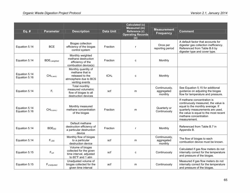
Organic Waste Digestion Project Protocol Version 2.1, January 2014
65
Eq. # Parameter Description Data Unit
Calculated (c) Measured (m) Reference (r)
Operating Records (o)
Measurement Frequency Comment
Equation 5.14 BCE Biogas collection
efficiency of the biogas control system
Fraction r Once per reporting period
A default factor that accounts for digester gas collection inefficiency. Referenced from Table B.6 by digester type and cover type.
Equation 5.14 BDEi,weighted
Monthly weighted methane destruction
efficiency of the combustion device(s)
Fraction c Monthly
Equation 5.14 Equation 5.16 CH4,vent,i
Monthly quantity of methane that is released to the
atmosphere due to BCS venting events
tCH4 c Monthly
Equation 5.14 Fi
Total monthly measured volumetric flow of biogas to all destruction devices
scf m Continuously, aggregated
monthly
See Equation 5.15 for additional guidance on adjusting the biogas flow for temperature and pressure.
Equation 5.14 Equation 5.16 CH4,conc,i
Monthly measured methane concentration
of the biogas Fraction m Quarterly or
Continuously
If methane concentration is continuously measured, the value is equal to the monthly average. If quarterly measurements are used, the value is equal to the most recent methane concentration measurement.
Equation 5.14 BDEDD
Default methane destruction efficiency of a particular destruction
device
Fraction r Monthly Referenced from Table B.7 in Appendix B.
Equation 5.14 Fi,DD Monthly flow of biogas
to a particular destruction device
scf m Continuously, aggregated
monthly
The flow of biogas to each combustion device must be known.
Equation 5.15 Fscf
Volume of biogas collected for the given time interval, adjusted
to 60°F and 1 atm
scf c Continuously Calculated if gas flow meters do not internally correct for the temperature and pressure of the biogas.
Equation 5.15 Funadjusted Unadjusted volume of
biogas collected for the given time interval
acf m Continuously Measured if gas flow meters do not internally correct for the temperature and pressure of the biogas.

Organic Waste Digestion Project Protocol Version 2.1, January 2014
66
Eq. # Parameter Description Data Unit
Calculated (c) Measured (m) Reference (r)
Operating Records (o)
Measurement Frequency Comment
Equation 5.15 T Measured temperature
of the biogas for the given time period
°R (°R = °F + 459.67) m Continuously
Measured to adjust the flow of biogas. No separate monitoring of temperature is necessary when using flow meters that automatically adjust flow volumes for temperature and pressure, expressing biogas volumes in normalized cubic feet.
Equation 5.15 P Measured pressure of
the biogas for the given time period
atm m Continuously
Measured to adjust the flow of biogas. No separate monitoring of pressure is necessary when using flow meters that automatically adjust flow volumes for temperature and pressure, expressing biogas volumes in normalized cubic feet.
Equation 5.16 MSBCS Maximum biogas
storage of the BCS system
scf r Once per reporting period
Obtained from digester system design plans. Necessary to quantify the release of methane to the atmosphere due to an uncontrolled venting event.
Equation 5.16 Fpw
Average total daily flow of biogas from the
digester for the entire week prior to the
venting event
scf/day m Weekly The average flow of biogas can be determined from the daily records from the previous week.
Equation 5.16 t
Number of days of the month that biogas is venting uncontrolled from the project’s BCS
Days m, o Monthly
The approximate number of days that the BCS vented biogas to the atmosphere, down to the nearest 4 hours, as determined from metering evidence, personnel accounts, and energy production records.
Equation 5.17 B0,EF Methane producing
capacity of the effluent stream ‘S’
/ r N/A
Project developers may use site-specific values that are determined based on the sampling approach provided in Section 6.1.3.2. Alternately, a value of 0.21 may be used for all effluent.
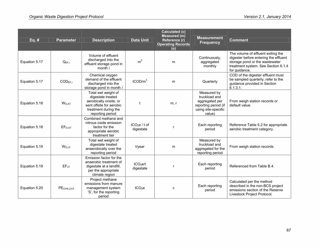
Organic Waste Digestion Project Protocol Version 2.1, January 2014
67
Eq. # Parameter Description Data Unit
Calculated (c) Measured (m) Reference (r)
Operating Records (o)
Measurement Frequency Comment
Equation 5.17 QEF,i
Volume of effluent discharged into the
effluent storage pond in month i
m3 m Continuously, aggregated
monthly
The volume of effluent exiting the digester before entering the effluent storage pond or the wastewater treatment system. See Section 6.1.4 for guidance.
Equation 5.17 CODEF,i
Chemical oxygen demand of the effluent
discharged into the storage pond in month i
tCOD/m3 m Quarterly
COD of the digester effluent must be sampled quarterly; refer to the guidance provided in Section 6.1.3.1.
Equation 5.18 WD,AT
Total wet weight of digestate treated
aerobically onsite, or sent offsite for aerobic treatment during the
reporting period
t m, r
Measured by truckload and
aggregated per reporting period (if using site-specific
value)
From weigh station records or default value.
Equation 5.18 EFD,AT
Combined methane and nitrous oxide emission
factor for the appropriate aerobic
treatment tier
tCO2e / t of digestate r Each reporting
period Reference Table 5.2 for appropriate aerobic treatment category.
Equation 5.19 WD,LF
Total wet weight of digestate treated
anaerobically over the reporting period
t/year m
Measured by truckload and
aggregated for the reporting period
From weigh station records.
Equation 5.19 EFLF
Emission factor for the anaerobic treatment of digestate at a landfill, per the appropriate
climate region
tCO2e/t digestate r Each reporting
period Referenced from Table B.4.
Equation 5.20 PECH4,LS,S
Project methane emissions from manure management system ‘S’, for the reporting
period
tCO2e c Each reporting period
Calculated per the method described in the non-BCS project emissions section of the Reserve Livestock Project Protocol.

Organic Waste Digestion Project Protocol Version 2.1, January 2014
68
Eq. # Parameter Description Data Unit
Calculated (c) Measured (m) Reference (r)
Operating Records (o)
Measurement Frequency Comment
Equation 5.21 BDEi
Monthly methane destruction efficiency of
the combustion device(s)
Fraction r, c Monthly
In the event that there is more than one destruction device in operation in any given month, the weighted average destruction efficiency from all combustion devices is to be used.

Organic Waste Digestion Project Protocol Version 2.1, January 2014
69
7 Reporting Parameters This section provides requirements and guidance on reporting rules and procedures. A priority of the Reserve is to facilitate consistent and transparent information disclosure among project developers. Project developers must submit verified emission reduction reports to the Reserve every 12 months at a minimum.
7.1 Project Submittal Documentation Project developers must provide the following documentation to the Reserve in order to register an OWD project:
Project Submittal form Project diagram from Monitoring Plan – see Appendix E (not public) Completed Reserve Livestock Calculation Tool, if used (not public) Signed Attestation of Title form Signed Attestation of Voluntary Implementation form Signed Attestation of Regulatory Compliance form Verification Report Verification Statement
Project developers must provide the following documentation each reporting period in order for the Reserve to issue CRTs for quantified GHG reductions:
Verification Report Verification Statement Project diagram from Monitoring Plan – see Appendix E (not public) Completed Reserve Livestock Calculation Tool, if used (not public) Signed Attestation of Title form Signed Attestation of Voluntary Implementation form Signed Attestation of Regulatory Compliance form
At a minimum, the above project documentation will be available to the public via the Reserve’s online registry. Further disclosure and other documentation may be made available on a voluntary basis through the Reserve. Project submittal forms can be found at http://www.climateactionreserve.org/how/program/documents/.
7.2 Record Keeping For purposes of independent verification and historical documentation, project developers are required to keep all information outlined in this protocol for a period of 10 years after the information is generated or 7 years after the last verification. This information will not be publicly available, but may be requested by the verifier or the Reserve. System information the project developer should retain includes:
All data inputs for the calculation of GHG reductions, including all required sampled data Copies of all solid waste, air, water, and land use permits relevant to project activities;
Notices of Violations (NOVs) relevant to project activities; and any administrative or legal consent orders relevant to project activities dating back at least 3 years prior to the project start date, and for each subsequent year of project operation
Organic Waste Digestion Project Protocol Version 2.1, January 2014
70
Project developer attestation of compliance with regulatory requirements relating to the OWD project
Biogas flow meter information (model number, serial number, manufacturer’s calibration procedures)
Methane monitor information (model number, serial number, calibration procedures) Destruction device monitor information (model number, serial number, calibration
procedures) Cleaning and inspection records for all biogas meters Field check results for all biogas meters Calibration results for all meters Destruction device monitoring data for each destruction device Biogas flow and methane concentration data Food and food-soiled paper waste weight data Food and food-soiled paper waste characterization data Wastewater and digester effluent flow meter information (model number, serial number,
manufacturer’s calibration procedures) Wastewater and digester effluent flow data Results of CO2e reduction calculations Initial and subsequent verification records and results All maintenance records relevant to the biogas control system, monitoring equipment,
and destruction devices Calibrated portable gas analyzer information that the project developer should retain includes:
Date, time, and location of methane measurement Methane content of biogas (% by volume) for each measurement Methane measurement instrument type and serial number Date, time, and results of instrument calibration Corrective measures taken if instrument does not meet performance specifications
7.3 Reporting Period and Verification Cycle Project developers must report GHG reductions resulting from project activities during each reporting period. Although projects must be verified every 12 months at a minimum, the Reserve will accept verified emission reduction reports more frequently, should the project developer choose to have a reporting period and verification schedule of less than 12 months. A reporting period cannot exceed 12 months, and no more than 12 months of emission reductions can be verified at once, except during a project’s first verification, which may include historical emission reductions from prior years.

Organic Waste Digestion Project Protocol Version 2.1, January 2014
71
8 Verification Guidance This section provides verification bodies with guidance on verifying GHG emission reductions associated with the diversion of organic waste and/or wastewater away from anaerobic treatment and disposal systems and to a biogas control system (BCS). This verification guidance supplements the Reserve’s Verification Program Manual and describes verification activities specifically related to OWD projects. Verification bodies trained to verify organic waste digestion projects must be familiar with the following documents:
Climate Action Reserve Program Manual Climate Action Reserve Verification Program Manual Climate Action Reserve Livestock Project Protocol Climate Action Reserve Organic Waste Digestion Project Protocol
The Reserve’s Program Manual, Verification Program Manual, and project protocols are designed to be compatible with each other and are available on the Reserve’s website at http://www.climateactionreserve.org. Only Reserve-approved verification bodies are eligible to verify OWD project reports. Verification bodies approved under other project protocol types are not permitted to verify OWD projects. Information about verification body accreditation and Reserve project verification training can be found on the Reserve website at http://www.climateactionreserve.org/how/verification/.
8.1 Standard of Verification The Reserve’s standard of verification for OWD projects is the OWD Project Protocol (this document), the Livestock Project Protocol (for manure co-digestion projects), the Reserve Program Manual, and the Verification Program Manual. To verify an OWD project report, verification bodies apply the guidance in the Verification Program Manual and this section of the protocol to the standards described in Sections 2 through 7 of this protocol. Sections 2 through 7 provide eligibility rules, methods to calculate emission reductions, performance monitoring instructions and requirements, and procedures for reporting project information to the Reserve.
8.2 Monitoring Plan The Monitoring Plan serves as the basis for verification bodies to confirm that the monitoring and reporting requirements in Section 6 and Section 7 have been met, and that consistent, rigorous monitoring and record-keeping is ongoing at the project site. Verification bodies shall confirm that the Monitoring Plan covers all aspects of monitoring and reporting contained in this protocol and specifies how data for all relevant parameters in Table 6.1 are collected and recorded.
8.3 Verifying Project Eligibility Verification bodies must affirm an OWD project’s eligibility according to the rules described in this protocol. The table below outlines the eligibility criteria for OWD projects. This table does not present all criteria for determining eligibility comprehensively; verification bodies must also look to Section 3 and the verification items list in Table 8.2.
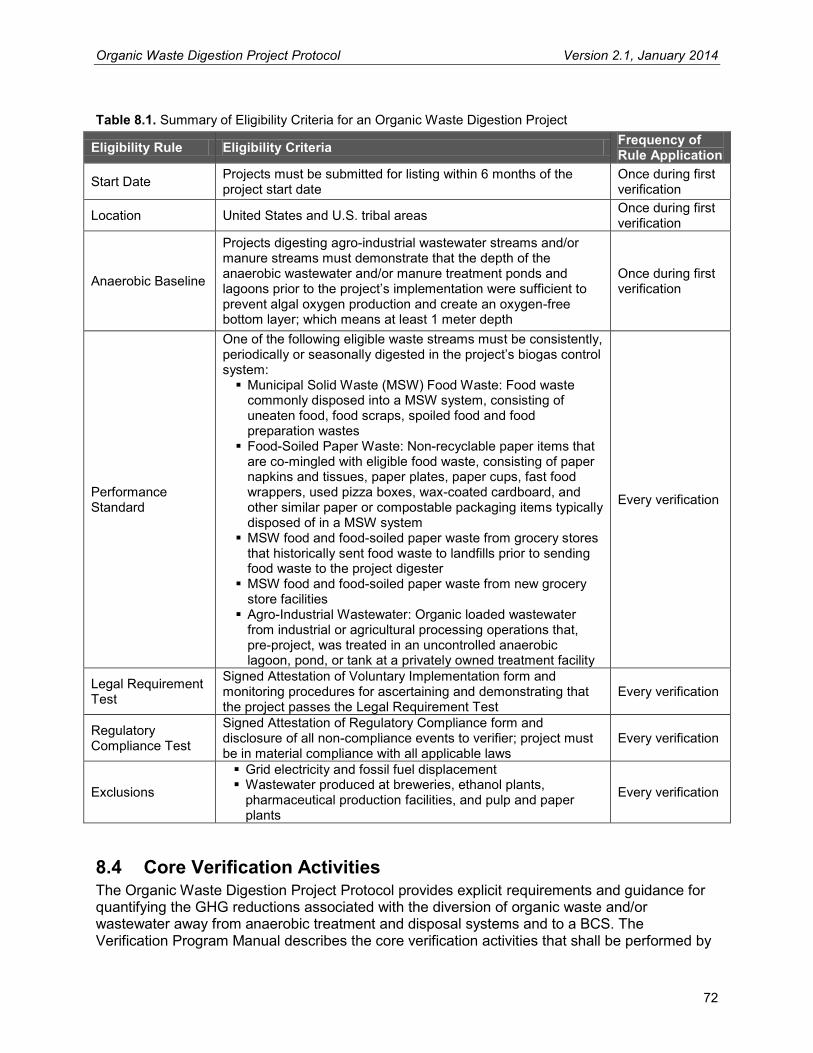
Organic Waste Digestion Project Protocol Version 2.1, January 2014
72
Table 8.1. Summary of Eligibility Criteria for an Organic Waste Digestion Project
Eligibility Rule Eligibility Criteria Frequency of Rule Application
Start Date Projects must be submitted for listing within 6 months of the project start date
Once during first verification
Location United States and U.S. tribal areas Once during first verification
Anaerobic Baseline
Projects digesting agro-industrial wastewater streams and/or manure streams must demonstrate that the depth of the anaerobic wastewater and/or manure treatment ponds and lagoons prior to the project’s implementation were sufficient to prevent algal oxygen production and create an oxygen-free bottom layer; which means at least 1 meter depth
Once during first verification
Performance Standard
One of the following eligible waste streams must be consistently, periodically or seasonally digested in the project’s biogas control system:
Municipal Solid Waste (MSW) Food Waste: Food waste commonly disposed into a MSW system, consisting of uneaten food, food scraps, spoiled food and food preparation wastes
Food-Soiled Paper Waste: Non-recyclable paper items that are co-mingled with eligible food waste, consisting of paper napkins and tissues, paper plates, paper cups, fast food wrappers, used pizza boxes, wax-coated cardboard, and other similar paper or compostable packaging items typically disposed of in a MSW system
MSW food and food-soiled paper waste from grocery stores that historically sent food waste to landfills prior to sending food waste to the project digester
MSW food and food-soiled paper waste from new grocery store facilities
Agro-Industrial Wastewater: Organic loaded wastewater from industrial or agricultural processing operations that, pre-project, was treated in an uncontrolled anaerobic lagoon, pond, or tank at a privately owned treatment facility
Every verification
Legal Requirement Test
Signed Attestation of Voluntary Implementation form and monitoring procedures for ascertaining and demonstrating that the project passes the Legal Requirement Test
Every verification
Regulatory Compliance Test
Signed Attestation of Regulatory Compliance form and disclosure of all non-compliance events to verifier; project must be in material compliance with all applicable laws
Every verification
Exclusions
Grid electricity and fossil fuel displacement Wastewater produced at breweries, ethanol plants,
pharmaceutical production facilities, and pulp and paper plants
Every verification
8.4 Core Verification Activities The Organic Waste Digestion Project Protocol provides explicit requirements and guidance for quantifying the GHG reductions associated with the diversion of organic waste and/or wastewater away from anaerobic treatment and disposal systems and to a BCS. The Verification Program Manual describes the core verification activities that shall be performed by
Organic Waste Digestion Project Protocol Version 2.1, January 2014
73
verification bodies for all project verifications. They are summarized below in the context of an OWD project, but verification bodies must also follow the general guidance in the Verification Program Manual. Verification is a risk assessment and data sampling effort designed to ensure that the risk of reporting error is assessed and addressed through appropriate sampling, testing, and review. The three core verification activities are:
1. Identifying emission sources, sinks, and reservoirs (SSRs) 2. Reviewing GHG management systems and estimation methodologies 3. Verifying emission reduction estimates
Identifying emission sources, sinks, and reservoirs The verification body reviews for completeness the sources, sinks, and reservoirs identified for a project, such as, inter alia, food waste disposal at landfills, anaerobic wastewater treatment, and/or manure treatment at livestock operations (if co-digesting manure with waste streams).
Reviewing GHG management systems and estimation methodologies The verification body reviews and assesses the appropriateness of the methodologies and management systems that the OWD project operator uses to gather data and calculate baseline and project emissions.
Verifying emission reduction estimates The verification body further investigates areas that have the greatest potential for material misstatements and then confirms whether or not material misstatements have occurred. This involves site visits to the project to ensure the systems on the ground correspond to and are consistent with data provided to the verification body. In addition, the verification body recalculates a representative sample of the performance or emissions data for comparison with data reported by the project developer in order to double-check the calculations of GHG emission reductions.
8.5 OWD Verification Items The following tables provide lists of items that a verification body needs to address while verifying an OWD project. The tables include references to the section in the protocol where requirements are further specified. The table also identifies items for which a verification body is expected to apply professional judgment during the verification process. Verification bodies are expected to use their professional judgment to confirm that protocol requirements have been met in instances where the protocol does not provide (sufficiently) prescriptive guidance. For more information on the Reserve’s verification process and professional judgment, please see the Verification Program Manual. Note: These tables shall not be viewed as a comprehensive list or plan for verification activities, but rather guidance on areas specific to OWD projects that must be addressed during verification.
8.5.1 Project Eligibility and CRT Issuance Table 8.2 lists the criteria for reasonable assurance with respect to eligibility and CRT issuance for OWD projects. These requirements determine if a project is eligible to register with the Reserve and/or have CRTs issued for the reporting period. If any one requirement is not met,

Organic Waste Digestion Project Protocol Version 2.1, January 2014
74
either the project may be determined ineligible or the GHG reductions from the reporting period (or subset of the reporting period) may be ineligible for issuance of CRTs, as specified in Sections 2, 3 and 6. Table 8.2. Eligibility Verification Items
Protocol Section Eligibility Qualification Item
Apply Professional Judgment?
2.2 Verify that the project meets the definition of an OWD project No 3.2 Verify eligibility of project start date No 3.2 Verify accuracy of project start date based on operational records Yes 3.3 Verify that project is within its 10 year crediting period No
3.4 Verify that all pre-project wastewater and/or manure treatment lagoons/ponds/tanks were of sufficient depth to ensure an oxygen-free bottom layer (> 1m)
Yes
3.4.1
If co-digesting manure with eligible organic waste, verify that all livestock operations contributing manure to the digestion project meet eligibility requirements per the most recent Livestock Project Protocol (as of the time of project submittal)
No
3.4.2
If one or more waste streams are sourced from Greenfield facilities (including, but not limited to, the project facility), verify that all wastewater was previously managed in an open anaerobic lagoon and the relevant Livestock Project Protocol Greenfield guidance is applied for all manure waste streams.
Yes
3.5.1 Verify that the project meets the Performance Standard Test No
3.5.1
Verify that the project has documentation showing that all eligible waste streams originating from grocery stores or supermarkets were previously landfilled prior to the date that the waste is first delivered to the project digester
Yes
3.5.2 Confirm execution of the Attestation of Voluntary Implementation form to demonstrate eligibility under the Legal Requirement Test No
3.5.2 Verify that the project Monitoring Plan contains a mechanism for ascertaining and demonstrating that the project passes the Legal Requirement Test at all times
No
3.5.2.1 Verify that any food waste streams are eligible per Section 3.5.2 if the project is digesting food waste originating from a jurisdiction that has a mandatory food waste diversion ordinance or regulation
Yes
3.6
Verify that the project activities comply with applicable laws by reviewing any instances of material non-compliance provided by the project developer and performing a risk-based assessment to confirm the statements made by the project developer in the Attestation of Regulatory Compliance form
Yes
3.7 Verify ownership of the reductions by reviewing the Attestation of Title No
6 Verify that monitoring meets the requirements of the protocol. If it does not, verify that variance has been approved for monitoring variations No
6
Verify that all gas flow meters and continuous methane analyzers adhered to the inspection, cleaning, and calibration schedule specified in the protocol. If they do not, verify that variance has been approved for monitoring variations or that adjustments have been made to data per the protocol requirements
No
6 Verify that adjustments for failed calibrations were properly applied No 6,Appendix D If used, verify that data substitution methodology was properly applied No

Organic Waste Digestion Project Protocol Version 2.1, January 2014
75
8.5.2 Quantification Table 8.3 lists the items that verification bodies shall include in their risk assessment and re-calculation of the project’s GHG emission reductions. These quantification items inform any determination as to whether there are material and/or immaterial misstatements in the project’s GHG emission reduction calculations. If there are material misstatements, the calculations must be revised before CRTs are issued. Table 8.3. Quantification Verification Items
Protocol Section Quantification Item
Apply Professional Judgment?
4 Verify that all SSRs in the GHG Assessment Boundary are accounted for No
5 Verify that the calculated baseline is compared with the total amount of methane metered and destroyed by the project, and the lesser of the two values is used as the baseline for the GHG reduction calculation
No
5.1 Verify that the baseline emissions from different eligible waste streams are properly aggregated No
5.1.1 Verify that the correct k value is used for each food waste stream’s baseline calculation No
5.1.1 Verify that the FOD equation and/or the look-up table (Table B.3) is used correctly for each food waste stream No
5.1.1 Verify that the weight of eligible food waste used for the baseline calculation is determined correctly No
5.1.2 Verify that COD sampling of wastewater is performed monthly according to the guidance in Section 6.1.3.1 No
5.1.2 Verify that the correct MCF factor was used for the wastewater baseline calculation for each eligible wastewater stream No
5.1.2 Verify that the B0 value used for the wastewater baseline calculation is the default, or a site-specific value determined according to the guidance of Section 6.1.1.1
No
5.1.3, 5.2.6
Verify that the baseline and project emissions calculations for all manure waste streams digested by the OWD project are calculated according to the requirements of the most recent (as of the time of project submittal) Livestock Project Protocol
No
5.2 Verify that the project emissions calculations were calculated according to the protocol with the appropriate data No
5.2.1 Verify that the project developer correctly monitored, quantified, and aggregated electricity use Yes
5.2.1 Verify that the project developer correctly monitored, quantified, and aggregated fossil fuel use Yes
5.2.1 Verify that the project developer applied the correct emission factors for fossil fuel combustion and grid-delivered electricity No
5.2.2 Verify that the project developer applied the correct methane destruction efficiencies No
5.2.2 Verify that the project developer correctly quantified the amount of uncombusted methane No
5.2.2.1 Verify that methane emissions resulting from any venting events or temporary project shutdowns are estimated correctly Yes
5.2.3 Verify that COD sampling of liquid digester effluent is performed quarterly if the project stores liquid effluent in a storage pond No
5.2.3 Verify that the correct MCF factor was used for the effluent storage pond No
5.2.4 If the project aerobically treats (composts) digestate material either onsite or offsite, verify that the aerobic treatment tier from Table 5.2 Yes

Organic Waste Digestion Project Protocol Version 2.1, January 2014
76
Protocol Section Quantification Item
Apply Professional Judgment?
used for the calculation is consistent with the project-specific management of digestate material
5.2.5 Verify that the weight of digestate disposed anaerobically is determined correctly based off of appropriate data No
5.3 Verify that the project developer correctly monitored and quantified the amount of methane destroyed by the project No
8.5.3 Risk Assessment Verification bodies will review the following items in Table 8.4 to guide and prioritize their assessment of data used in determining eligibility and quantifying GHG emission reductions. Table 8.4. Risk Assessment Verification Items
Protocol Section Items that Inform Risk Assessment
Apply Professional Judgment?
6 Verify that the project Monitoring Plan is sufficiently rigorous to support the requirements of the protocol and proper operation of the project Yes
6 Verify that the BCS was operated and maintained according to manufacturer specifications No
6 Verify that appropriate monitoring equipment is in place to meet the requirements of the protocol No
6 Verify that the individual or team responsible for managing and reporting project activities are qualified to perform this function Yes
6 Verify that appropriate training was provided to personnel assigned to greenhouse gas reporting duties Yes
6 Verify that all contractors are qualified for managing and reporting greenhouse gas emissions if relied upon by the project developer. Verify that there is internal oversight to assure the quality of the contractor’s work
Yes
6.1.3.1 Verify that the COD sampling and analysis was done by professionals experienced with the procedures used to determine COD as described in the Standard Method approach
Yes
6.1.3.2
Verify that all samples used to determine a site-specific B0 factor are analyzed at an independent third-party laboratory that is experienced with the Biochemical Methane Potential (BMP) Assay procedure used to determine the maximum methane potential value of wastewaters
Yes
7.2 Verify that all required records have been retained by the project developer No
8.6 Completing Verification The Verification Program Manual provides detailed information and instructions for verification bodies to finalize the verification process. It describes completing a Verification Report, preparing a Verification Statement, submitting the necessary documents to the Reserve, and notifying the Reserve of the project’s verified status.
Organic Waste Digestion Project Protocol Version 2.1, January 2014
77
9 Glossary of Terms Accredited verifier A verification firm approved by the Climate Action Reserve to
provide verification services for project developers.
Additionality Projects that are digesting one or more eligible feedstocks in a biogas control system (BCS) are deemed to exceed common practice, and that are not mandated by regulation.
Agro-industrial wastewater Organic loaded wastewater from industrial or agricultural processing operations that, pre-project, was treated in an uncontrolled anaerobic lagoon, pond, or tank at a privately owned treatment facility. Excluded from eligibility based on the Reserve’s performance standard analysis are wastewaters produced at breweries, ethanol plants, pharmaceutical production facilities, and pulp and paper plants.
Anaerobic Pertaining to or caused by the absence of oxygen.
Anthropogenic emissions GHG emissions resultant from human activity that are considered to be an unnatural component of the Carbon Cycle (i.e. fossil fuel destruction, de-forestation, etc.).
Biogas Gas generated as a result of decomposition of organic materials under anaerobic conditions. Generally consists primarily of methane and carbon dioxide, with other trace gases.
Biogas control system (BCS)
A waste management system consisting of an anaerobic digester, biogas collection and metering equipment, and biogas destruction device(s).
Biogenic CO2 emissions CO2 emissions resulting from the destruction and/or aerobic decomposition of organic matter. Biogenic emissions are considered to be a natural part of the Carbon Cycle, as opposed to anthropogenic emissions.
Carbon dioxide (CO2)
The most common of the six primary greenhouse gases, consisting of a single carbon atom and two oxygen atoms.
CO2 equivalent (CO2e)
The quantity of a given GHG multiplied by its total global warming potential. This is the standard unit for comparing the degree of warming which can be caused by different GHGs.
Chemical oxygen demand (COD)
The chemical oxygen demand (COD) is the amount of oxygen consumed to completely chemically oxidize the organic water constituents to inorganic end products. COD is an important, rapidly measured variable for the approximate determination of the organic matter content of water samples.
Digester effluent The largely decomposed residue material that has passed through the anaerobic digester system.
Digestate The solid residue material separated from the liquid digester effluent stream.

Organic Waste Digestion Project Protocol Version 2.1, January 2014
78
Direct emissions Greenhouse gas emissions from sources that are owned or controlled by the reporting entity.
Emission factor (EF)
A unique value for determining an amount of a greenhouse gas emitted for a given quantity of activity data (e.g. metric tons of carbon dioxide emitted per barrel of fossil fuel burned).
First Order Decay model (FOD model)
A calculation developed to model the decay of waste under anaerobic conditions, based off of first-order kinetic equations.
Flare A destruction device that uses an open flame to burn combustible gases with combustion air provided by uncontrolled ambient air around the flame.
Fossil fuel A fuel, such as coal, oil, and natural gas, produced by the decomposition of ancient (fossilized) plants and animals.
Greenfield project A project implemented at new industrial facilities that have no prior wastewater treatment system.
Greenhouse gas (GHG)
Carbon dioxide (CO2), methane (CH4), nitrous oxide (N2O), sulfur hexafluoride (SF6), hydrofluorocarbons (HFCs), or perfluorocarbons (PFCs).
GHG reservoir A physical unit or component of the biosphere, geosphere, or hydrosphere with the capability to store or accumulate a GHG that has been removed from the atmosphere by a GHG sink or a GHG captured from a GHG source.
GHG sink A physical unit or process that removes GHG from the atmosphere.
GHG source A physical unit or process that releases GHG into the atmosphere.
Global warming potential (GWP)
The ratio of radiative forcing (degree of warming to the atmosphere) that would result from the emission of one unit of a given GHG compared to one unit of CO2.
Indirect emissions Reductions in GHG emissions that occur at a location other than where the reduction activity is implemented, and/or at sources not owned or controlled by project participants.
Landfill A defined area of land or excavation that receives or has previously received waste that may include household waste, commercial solid waste, non-hazardous sludge, and industrial solid waste.
Landfill gas (LFG)
Gas resulting from the decomposition of wastes placed in a landfill. Typically, landfill gas contains methane, carbon dioxide and other trace organic and inert gases.
Materials Recovery Facility (MRF)
A specialized plant that receives, sorts, and processes MSW in order to extract materials of value that would ordinarily otherwise go to a landfill.
Organic Waste Digestion Project Protocol Version 2.1, January 2014
79
MRF fines Residual material from the processing of mixed MSW at a Materials Recovery Facility, characterized by small particle size and relatively high organics content as compared to typical mixed MSW loads. This material is not source-separated.
Metric ton or “tonne” (t)
A common international measurement for the quantity of GHG emissions, equivalent to about 2204.6 pounds or 1.1 short tons.
Methane (CH4)
A potent GHG with a GWP of 21, consisting of a single carbon atom and four hydrogen atoms.
MMBtu One million British thermal units.
Mobile combustion Emissions from the transportation of materials, products, waste, and employees resulting from the combustion of fuels in company owned or controlled mobile combustion sources (e.g. cars, trucks, tractors, dozers, etc.).
Mixed MSW Non-source separated waste consisting of organic and inorganic components, reflecting waste typically disposed of at a landfill.
MSW food waste Non-industrial food waste commonly disposed into a MSW system, consisting of uneaten food, spoiled food and food preparation wastes from homes, restaurants, kitchens, grocery stores, campuses, cafeterias, and similar institutions.
National Emission Standards for Hazardous Air Pollutants (NESHAP)
Federal emission control standards codified in 40 CFR 63. Subpart AAAA of Part 63 prescribes emission limitations for MSW landfills.
New Source Performance Standards (NSPS)
Federal emission control standards codified in 40 CFR 60. Subpart WWW of Part 60 prescribes emission limitations for MSW landfills.
Project baseline A “business as usual” GHG emission assessment against which GHG emission reductions from a specific GHG reduction activity are measured.
Project developer An entity that undertakes a GHG project, as identified in the OWD Project Protocol, Section 2.
Resource Conservation and Recovery Act (RCRA)
Federal legislation under which solid and hazardous waste disposal facilities are regulated.
Stationary combustion source A stationary source of emissions from the production of electricity, heat, or steam, resulting from combustion of fuels in boilers, furnaces, turbines, kilns, and other facility equipment.
Verification The process used to ensure that a given participant’s greenhouse gas emissions or emission reductions have met the minimum quality standard and complied with the Reserve’s procedures and protocols for calculating and reporting GHG emissions and emission reductions.

Organic Waste Digestion Project Protocol Version 2.1, January 2014
80
Verification body A Reserve-approved firm that is able to render a verification opinion and provide verification services for operators subject to reporting under this protocol.
Waste stream For the purpose of this protocol, an eligible waste stream is defined as an eligible waste type per the eligibility requirements in Section 3.5.1 (post-consumer food waste or agro-industrial wastewater), originating from a specific source or collection route. Examples:
Residential SSO food and paper waste from a specific county or municipal jurisdiction
Commercial SSO food and paper waste from a specific collection route
Wastewater from a specific industrial plant

Organic Waste Digestion Project Protocol Version 2.1, January 2014
81
10 References Alberta Environment, Specified Gas Emitters Regulation. Quantification Protocol for the Anaerobic Decomposition of Agricultural Materials, Version 1 (2007). Brown, S., Kruger, C., & Subler, S. (2008). Greenhouse Gas Balance for Composting Operations. Journal of Environmental Quality, Volume 37, Pg 1396-1410. Chicago Climate Exchange, Draft Guidelines for Methane Avoidance Projects (2008). Climate Action Reserve, Landfill Project Protocol. http://www.climateactionreserve.org/how/protocols/adopted/landfill/current-landfill-project-protocol/ Climate Action Reserve, Livestock Project Protocol. http://www.climateactionreserve.org/how/protocols/adopted/livestock/current-livestock-project-protocol/ GE AES Greenhouse Gas Services, LLC. Methodology for Waste Water Treatment Methane Capture and Destruction Projects, Version 1.0 (2007). GE AES Greenhouse Gas Services, LLC. Methodology for Waste Water Treatment Methane Capture and Destruction Projects, Version 1.1 (2008). Hansen, T.L., Sommer, S.G., Gabriel, S., & Christensen, T.H. (2006). Methane Production During Storage of Anaerobically Digested Municipal Organic Waste. Journal of Environmental Quality, Volume 35, Pg 830-836. International Standards Organization (ISO). ISO14064-1 – Specification with guidance at the organization level for quantification and reporting of greenhouse gas emissions and removals (2006). International Standards Organization (ISO). ISO14064-2 – Specification with guidance at the project level for quantification, monitoring and reporting of greenhouse gas emission reductions or removal enhancements (2006). IPCC, 2006. Guidelines for National Greenhouse Gas Inventories. (Volume 4 - Agriculture, Forestry and Other Land Use). Webpage: http://www.ipcc-nggip.iges.or.jp/public/2006gl/index.htm IPCC 2006 Guidelines for National Greenhouse Gas Inventories. (Volume 5 – Waste). Webpage: http://www.ipcc-nggip.iges.or.jp/public/2006gl/index.htm Recycled Organics Unit (2003). Life Cycle Inventory and Life Cycle Assessment for Windrow Composting Systems. Report prepared for NSW Department of Environment and Conservation (Sustainability Programs Division), Published by Recycled Organics Unit, The University of New South Wales, Sydney. Regional Greenhouse Gas Initiative, Draft Model Rule (January 2007). Smith, A., K. Brown, S. Ogilvie, K. Rushton, and J. Bates. (2001). Waste management options and climate change: Final report to the European Commission, DG Environment. Available at http://ec.europa.eu/environment/waste/studies/climate_change.htm Spajic, R.; Burns, R.; Moody, L, Kralik, D. (2009). Use of Biochemical Methane Potential (BMP) Assays for Predicting and Enhancing Anaerobic Digester Performance. Available at: http://sa.pfos.hr/sa2009/radovi/pdf/Radovi/r10-009.pdf
Organic Waste Digestion Project Protocol Version 2.1, January 2014
82
United Nations Food and Agriculture Organization, Chemical Oxygen Demand Definitions Webpage: http://www.fao.org/gtos/tems/variable_show.jsp?VARIABLE_ID=123 United Nations Framework Convention on Climate Change (UNFCCC), Approved Consolidated Baseline and Monitoring Methodology ACM0014, “Mitigation of greenhouse gas emissions from treatment of industrial wastewater,” Clean Development Mechanism Version 02.1, Sectoral Scopes 13 (2008). United Nations Framework Convention on Climate Change (UNFCCC), Approved Baseline and Monitoring Methodology AM0073, “GHG emission reductions through multi-site manure collection and treatment in a central plant,” Clean Development Mechanism Version 01, Sectoral Scopes 13 and 15 (2008). United Nations Framework Convention on Climate Change (UNFCCC), Approved Baseline and Monitoring Methodology AM0025, “Avoided emissions from organic waste through alternative waste treatment processes,” Clean Development Mechanism Version 11, Sectoral Scopes 01 and 13 (2008). United Nations Framework Convention on Climate Change (UNFCCC), Approved Small-Scale Methodology III.E, “Avoidance of methane production from decay of biomass through controlled combustion, gasification or mechanical/thermal treatment,” Clean Development Mechanism Version 15.1, Sectoral Scopes 13 (2007). United Nations Framework Convention on Climate Change (UNFCCC), Approved Small-Scale Methodology III.F, “Avoidance of methane emissions through controlled biological treatment of biomass,” Clean Development Mechanism Version 06, Sectoral Scopes 13 (2008). United Nations Framework Convention on Climate Change (UNFCCC), Annex 10 Methodological Tool, “Tool to determine methane emissions avoided from dumping waste at a solid waste disposal site,” Clean Development Mechanism Version 04, (2008). U.S. Environmental Protection Agency - Climate Leaders, Greenhouse Gas Inventory Protocol Offset Project Methodology for Project Type: Managing Manure with Biogas Recovery Systems (2008). U.S. Environmental Protection Agency, Inventory of U.S. Greenhouse Gas Emissions and Sinks: 1990-2006, EPA-430-R-07-002 (April 2007). U.S. Environmental Protection Agency, Solid Waste Management and Greenhouse Gases; A Lifecycle Assessment of Emissions and Sinks, Third Edition (2006). Available at: http://epa.gov/climatechange/wycd/waste/SWMGHGreport.html U.S. Environmental Protection Agency Region 9, Anaerobic Digestion of Food Waste - Funding Opportunity No. EPA-R9-WST-06-004 Final Report. (2008) Available at: http://www.epa.gov/region09/waste/organics/ad/EBMUDFinalReport.pdf

Organic Waste Digestion Project Protocol Version 2.1, January 2014
83
Appendix A Associated Environmental Impacts Organic waste and manure digestion projects have many documented environmental benefits, including air emission reductions, water quality protection, and electricity generation. These benefits are the result of practices and technologies that are well managed, well implemented, and well designed. However, in cases where practices or technologies are poorly or improperly designed, implemented, and/or managed, local air and water quality could be compromised. With regard to air quality, there are a number of factors that must be considered and addressed to realize the environmental benefits of a biogas project and reduce or avoid potential negative impacts. Uncontrolled emissions from combustion of biogas may contain between 200 to 300 ppm NOX. The anaerobic treatment process creates intermediates such as ammonia, hydrogen sulfide, orthophosphates, and various salts, all of which must be properly controlled or captured. In addition, atmospheric releases at locations offsite where bio-gas is shipped may negate or decrease the benefit of emissions controls onsite. Thus, while devices such as Selective Catalyst Reduction (SCR) units can reduce NOX emissions and proper treatment system operation can control intermediates, improper design or operation may lead to violations of federal, state, and local air quality regulations as well as release of toxic air contaminants. With regard to water quality, it is critical that project developers and managers ensure digester integrity and fully consider and address post-digestion management of the effluent in order to adequately manage nutrient loading and avoid contamination of local waterways and groundwater resources. Catastrophic digester failures; leakage from pipework and tanks; and lack of containment in waste storage areas are all examples of potential problems. Further, application of improperly treated digestate and/or improper application timing or rates of digestate to agricultural land may lead to increased nitrogen oxide emissions, soil contamination, and/or nutrient leaching, thus negating or reducing benefits of the project overall. As specified in Section 3.6, Project developers must comply with all local, state, and national air and water quality regulations pertaining to project activity. Projects must be designed and implemented to mitigate potential releases of pollutants such as those described, and project managers must acquire the appropriate local permits prior to installation to prevent violation of the law. The Reserve agrees that GHG emission reduction projects should not undermine air and water quality efforts and will work with stakeholders to establish initiatives to meet both climate-related and localized environmental objectives.

Organic Waste Digestion Project Protocol Version 2.1, January 2014
84
Appendix B Data Lookup Tables Table B.1. Decay Rates (k) by Waste Type and Climate
Climatic Category (by Mean Annual Precipitation)
Food Waste Decay Rate kFW,S (yr-1)
Soiled Paper Decay Rate kSP,S (yr-1)*
Dry (0-25 inches) 0.072 0.031 Wet (25-50 inches) 0.144 0.063 Very Wet (50 + inches) 0.288 0.126 Source: Memorandum to Jennifer Brady, Office of Resource Conservation and Recovery, U.S. EPA: WARM Component-Specific Decay Rate Methods. ICF International, 2009. * Soiled paper decay rate assumed to be equal to the decay rate of mixed office paper, per communication with M. Barlaz.
Table B.2. Fraction of Waste Sent to Waste-to-Energy (WTE) Facilities
State WTES (Fraction)
ALABAMA 0.03 ALASKA 0.03 ARIZONA 0.00 ARKANSAS 0.01 CALIFORNIA 0.02 COLORADO 0.00 CONNECTICUT 0.65 DELAWARE 0.00 FLORIDA 0.25 GEORGIA 0.01 HAWAII 0.28 IDAHO 0.00 ILLINOIS 0.00 INDIANA 0.05 IOWA 0.01 KANSAS 0.00 KENTUCKY 0.00 LOUISIANA 0.04 MAINE 0.19 MARYLAND 0.20 MASSACHUSETTS 0.37 MICHIGAN 0.07 MINNESOTA 0.21 MISSISSIPPI 0.00 MISSOURI 0.01 MONTANA 0.01 NEBRASKA 0.00 NEVADA 0.00 NEW HAMPSHIRE 0.16 NEW JERSEY 0.15 NEW MEXICO 0.00

Organic Waste Digestion Project Protocol Version 2.1, January 2014
85
State WTES (Fraction)
NEW YORK 0.20 NORTH CAROLINA 0.01 NORTH DAKOTA 0.00 OHIO 0.00 OKLAHOMA 0.08 OREGON 0.04 PENNSYLVANIA 0.19 RHODE ISLAND 0.00 SOUTH CAROLINA 0.05 SOUTH DAKOTA 0.00 TENNESSEE 0.00 TEXAS 0.00 UTAH 0.04 VERMONT 0.09 VIRGINIA 0.13 WASHINGTON 0.04 WEST VIRGINIA 0.00 WISCONSIN 0.03 WYOMING 0.00
Source: Biocycle State of Garbage Report (2006), Table 3. (http://www.jgpress.com/images/art/0604/table3.gif) Table B.3. Gas Collection Fractions, by State
Landfill State
Total Annual Waste Acceptance at Open Landfills (tons) Fraction of Total Waste Accepted at
Open Landfills with Known or Potential LFG
Collection Systems
Gas Collection Fractions
Landfills with No LFG
Collection Systems
Landfills where LFG Collection Status is Unknown
Landfills with LFG Collection Systems
All Landfills
AK 182,674 72,900 350,000 605,574 70% 0.70 AL 3,249,929 1,040,000 4,731,995 9,021,924 64% 0.64 AR 471,646 936,455 1,408,101 67% 0.67 AZ 387,105 4,064,059 4,451,164 91% 0.91 CA 1,397,403 35,968,060 37,365,463 96% 0.96 CO 1,474,132 4,810,118 6,284,250 77% 0.77 CT 158,164 158,164 100% 1.00 DE 830,741 830,741 100% 1.00 FL 2,132,545 14,359,416 16,491,961 87% 0.87 GA 1,170,878 166,567 10,390,734 11,728,179 90% 0.90 HI 249,249 578,335 827,584 70% 0.70 IA 1,152,713 71,272 1,491,316 2,715,301 58% 0.58 ID 548,261 763,791 1,312,052 58% 0.58 IL 434,737 13,667,105 14,101,842 97% 0.97 IN 1,831,127 8,889,583 10,720,710 83% 0.83 KS 1,401,161 2,548,150 3,949,311 65% 0.65 KY 1,124,893 5,238,221 6,363,114 82% 0.82

Organic Waste Digestion Project Protocol Version 2.1, January 2014
86
Landfill State
Total Annual Waste Acceptance at Open Landfills (tons) Fraction of Total Waste Accepted at
Open Landfills with Known or Potential LFG
Collection Systems
Gas Collection Fractions
Landfills with No LFG
Collection Systems
Landfills where LFG Collection Status is Unknown
Landfills with LFG Collection Systems
All Landfills
LA 473,833 4,368,346 4,842,179 90% 0.90 MA 900 2,184,392 2,185,292 100% 1.00 MD 453,344 1,785,180 2,238,524 80% 0.80 ME 26,355 851,679 878,034 97% 0.97 MI 456,335 16,258,806 16,715,141 97% 0.97 MN 139,398 1,631,572 1,770,970 92% 0.92 MO 255,400 2,424,101 2,679,501 90% 0.90 MS 842,731 2,402,865 3,245,596 74% 0.74 MT 179,576 603,515 783,091 77% 0.77 NC 1,527,569 50,802 5,380,169 6,958,540 78% 0.78 ND 197,579 140,000 337,579 41% 0.41 NE 438,116 1,715,057 2,153,173 80% 0.80 NH 153,449 1,783,857 1,937,306 92% 0.92 NJ 4,095,824 4,095,824 100% 1.00 NM 83,321 1,348,266 1,431,587 94% 0.94 NV 341,668 3,507,687 3,849,355 91% 0.91 NY 526,891 7,430,008 7,956,899 93% 0.93 OH 2,163,712 17,047,685 19,211,397 89% 0.89 OK 828,876 3,161,706 3,990,582 79% 0.79 OR 373,788 4,386,823 4,760,611 92% 0.92 PA 289,651 18,361,866 18,651,517 98% 0.98 PR 1,814,530 1,401,900 3,216,430 44% 0.44 RI 9,760 1,507,847 1,517,607 99% 0.99 SC 429,431 6,470,888 6,900,319 94% 0.94 SD 273,700 178,321 452,021 39% 0.39 TN 524,290 5,131,608 5,655,898 91% 0.91 TX 2,657,648 25,701 18,413,494 21,096,843 87% 0.87 UT 1,220,353 1,360,428 2,580,781 53% 0.53 VA 433,948 125,755 13,048,150 13,607,853 97% 0.97 VI 85,000 85,000 100% 1.00 VT 11,788 520,000 531,788 98% 0.98 WA 203,059 4,246,249 4,449,308 95% 0.95 WI 95,026 8,457,871 8,552,897 99% 0.99
WV 385,188 26,496 1,381,594 1,793,278 79% 0.79
WY 275,453 275,453 0% 0%
Grand Total 35,295,119 1,579,493 272,848,997 309,723,609 89% N/A
Source: U.S. EPA Landfill Methane Outreach Program (LMOP) Database (2012).

Organic Waste Digestion Project Protocol Version 2.1, January 2014
87
Table B.4. Digestate Emission Factors by Climate Region
Decay Rate (k Value) Digestate Emission Factor* (tCO2e/t waste)
Dry 0.067 Wet 0.150 Very Wet 0.218
*The digestate emission factor is calculated using an FOD model with IPCC default values for sludge waste. Table B.5. Methane Conversion Factor (MCF) for Wastewater Treatment Systems
Type of Wastewater Treatment System MCF Lower Bound
Anaerobic reactor without methane capture 0.8 Anaerobic shallow lagoon (depth < 2 m) 0.1* Anaerobic deep lagoon (depth > 2m) 0.8
Source: IPCC Guidelines for National GHG Inventories, Volume 5, Chapter 6 (2006) * A lower bound value of 0.1 is used instead of 0.0, the lower bound in the IPCC guidelines. Table B.6. Biogas Collection Efficiency by Digester Type
Digester Type Cover Type Biogas Collection Efficiency (BCE) as a Decimal
Covered Anaerobic Lagoon
Bank-to-Bank, impermeable 0.95 Partial area (modular),
impermeable (0.95) x (% area covered)
Complete mix, plug flow, or fixed film
digester Enclosed vessel 0.98
Two stages of differing types
With flow metered for each stage
( ) ( ) ( ) ( )
No separate flow metering ( ) ( )
Adapted from: U.S. EPA Climate Leaders, Offset Project Methodology for Managing Manure and Biogas Recovery Systems, 2008. Table IIf (original table has been expanded upon).

Organic Waste Digestion Project Protocol Version 2.1, January 2014
88
Table B.7. Biogas Destruction Efficiency Default Values by Destruction Device
Biogas Destruction Device Biogas Destruction Efficiency (BDE)*
Open flare 0.96 Enclosed flare 0.995 Lean-burn internal combustion engine 0.936 Rich-burn internal combustion engine 0.995 Boiler 0.98 Microturbine or large gas turbine 0.995 Upgrade and use of gas as CNG/LNG fuel 0.95 Upgrade and injection into natural gas transmission and distribution pipeline 0.98**
Offsite use of gas under a direct-use agreement Per corresponding destruction device factor (not pipeline)
Source: The default destruction efficiencies for enclosed flares and electricity generation devices are based on a preliminary set of actual source test data provided by the Bay Area Air Quality Management District. The default destruction efficiency values are the lesser of the twenty fifth percentile of the data provided or 0.995. These default destruction efficiencies may be updated as more source test data is made available to the Reserve. * If available, the official source tested methane destruction efficiency shall be used in place of the default methane destruction efficiency. Otherwise, project developers have the option to use either the default methane destruction efficiencies provided, or the site specific methane destruction efficiencies as provided by a state or local agency accredited source test service provider, for each of the combustion devices used in the project case. If neither the state or locality relevant to the project site offer accreditation for source testing service providers, projects may use an accredited service provider from another U.S. state or domestic locality. Alternatively, projects may choose a non-accredited service provider, under the following conditions: 1) the service provider must provide verifiable evidence of prior testing which was accepted for compliance by a domestic regulatory agency, and 2) the prior testing procedures must be substantially similar to the procedures used for determining methane destruction efficiency for the project destruction device(s). ** The Revised 1996 IPCC Guidelines for National Greenhouse Gas Inventories gives a standard value for the fraction of carbon oxidized for gas destroyed of 99.5% (Reference Manual, Table 1.6, page 1.29). It also gives a value for emissions from processing, transmission and distribution of gas which would be a very conservative estimate for losses in the pipeline and for leakage at the end user (Reference Manual, Table 1.58, page 1.121). These emissions are given as 118,000kgCH4/PJ on the basis of gas consumption, which is 0.6%. Leakage in the residential and commercial sectors is stated to be 0 to 87,000kgCH4/PJ, which equates to 0.4%, and in industrial plants and power station the losses are 0 to 175,000kg/CH4/PJ, which is 0.8%. These leakage estimates are compounded and multiplied. The methane destruction efficiency for landfill gas injected into the natural gas transmission and distribution system can now be calculated as the product of these three efficiency factors, giving a total efficiency of (99.5% * 99.4% * 99.6%) 98.5% for residential and commercial sector users, and (99.5% * 99.4% * 99.2%) 98.1% for industrial plants and power stations.55
55 GE AES Greenhouse Gas Services, Landfill Gas Methodology, Version 1.0 (July 2007).

Organic Waste Digestion Project Protocol Version 2.1, January 2014
89
Table B.8. CO2 Emission Factors for Fossil Fuel Use
Fuel Type Heat Content Carbon Content
(Per Unit Energy) Fraction Oxidized
CO2 Emission Factor
(Per Unit Energy)
CO2 Emission Factor
(Per Unit Mass or Volume)
Coal and Coke MMBtu / Short ton kg C / MMBtu kg CO2 / MMBtu kg CO2 / Short
ton Anthracite Coal 25.09 28.26 1.00 103.62 2,599.83 Bituminous Coal 24.93 25.49 1.00 93.46 2,330.04 Sub-bituminous Coal 17.25 26.48 1.00 97.09 1,674.86 Lignite 14.21 26.30 1.00 96.43 1,370.32 Unspecified (Residential/ Commercial) 22.05 26.00 1.00 95.33 2,102.29 Unspecified (Industrial Coking) 26.27 25.56 1.00 93.72 2,462.12 Unspecified (Other Industrial) 22.05 25.63 1.00 93.98 2,072.19 Unspecified (Electric Utility) 19.95 25.76 1.00 94.45 1,884.53 Coke 24.80 31.00 1.00 113.67 2,818.93
Natural Gas (By Heat Content) Btu / Standard cubic foot kg C / MMBtu kg CO2 / MMBtu
kg CO2 / Standard cub.
ft. 975 to 1,000 Btu / Std cubic foot 975 – 1,000 14.73 1.00 54.01 Varies 1,000 to 1,025 Btu / Std cubic foot 1,000 – 1,025 14.43 1.00 52.91 Varies 1,025 to 1,050 Btu / Std cubic foot 1,025 – 1,050 14.47 1.00 53.06 Varies 1,050 to 1,075 Btu / Std cubic foot 1,050 – 1,075 14.58 1.00 53.46 Varies 1,075 to 1,100 Btu / Std cubic foot 1,075 – 1,100 14.65 1.00 53.72 Varies Greater than 1,100 Btu / Std cubic foot > 1,100 14.92 1.00 54.71 Varies
Weighted U.S. Average 1,029 14.47 1.00 53.06 0.0546 Petroleum Products MMBtu / Barrel kg C / MMBtu kg CO2 / MMBtu kg CO2 / gallon Asphalt & Road Oil 6.636 20.62 1.00 75.61 11.95 Aviation Gasoline 5.048 18.87 1.00 69.19 8.32 Distillate Fuel Oil (#1, 2 & 4) 5.825 19.95 1.00 73.15 10.15 Jet Fuel 5.670 19.33 1.00 70.88 9.57 Kerosene 5.670 19.72 1.00 72.31 9.76 LPG (average for fuel use) 3.849 17.23 1.00 63.16 5.79 Propane 3.824 17.20 1.00 63.07 5.74 Ethane 2.916 16.25 1.00 59.58 4.14 Isobutene 4.162 17.75 1.00 65.08 6.45 n-Butane 4.328 17.72 1.00 64.97 6.70 Lubricants 6.065 20.24 1.00 74.21 10.72 Motor Gasoline 5.218 19.33 1.00 70.88 8.81 Residual Fuel Oil (#5 & 6) 6.287 21.49 1.00 78.80 11.80 Crude Oil 5.800 20.33 1.00 74.54 10.29 Naphtha (<401 deg. F) 5.248 18.14 1.00 66.51 8.31 Natural Gasoline 4.620 18.24 1.00 66.88 7.36 Other Oil (>401 deg. F) 5.825 19.95 1.00 73.15 10.15 Pentanes Plus 4.620 18.24 1.00 66.88 7.36 Petrochemical Feedstocks 5.428 19.37 1.00 71.02 9.18 Petroleum Coke 6.024 27.85 1.00 102.12 14.65 Still Gas 6.000 17.51 1.00 64.20 9.17 Special Naphtha 5.248 19.86 1.00 72.82 9.10 Unfinished Oils 5.825 20.33 1.00 74.54 10.34 Waxes 5.537 19.81 1.00 72.64 9.58
Source: EPA Climate Leaders, Stationary Combustion Guidance (2007), Table B-2 except: Default CO2 emission factors (per unit energy) are calculated as: Carbon Content × Fraction Oxidized × 44/12. Default CO2 emission factors (per unit mass or volume) are calculated as: Heat Content x Carbon Content × Fraction Oxidized × 44/12× Conversion Factor (if applicable). Heat content factors are based on higher heating values (HHV).

Organic Waste Digestion Project Protocol Version 2.1, January 2014
90
Source: USGS, Hydrologic landscape regions of the United States (2003) Figure B.1. K-Value Categories in the U.S., by County

Organic Waste Digestion Project Protocol Version 2.1, January 2014
91
Appendix C Development of the Performance Standard The analysis to establish a performance standard for the Organic Waste Digestion Project Protocol was undertaken by Science Applications International Corporation (SAIC). It took place in January to May of 2009. The analysis culminated in two papers that provided performance standard options and recommendations to support the Reserve’s protocol development process, which the Reserve has incorporated into the protocol’s eligibility rules (see Section 3). The purpose of a performance standard is to establish a threshold that is significantly better than average greenhouse gas (GHG) production for a specified service, which, if met or exceeded by a project developer, satisfies the criterion of “additionality.” The Reserve’s project protocol focuses on the following emission reduction activity: the anaerobic digestion of organic wastes that were previously treated in uncontrolled anaerobic waste treatment systems. The analysis to establish the performance standard evaluated organic waste management practices in the specified categories of waste streams. The paper did not provide a detailed quantitative analysis of organic waste practices or volumes in the U.S. but rather provides a qualitative review of current practices and regulations for the identified waste categories. It did not provide a performance “threshold” or baseline of GHG emissions from organic waste. Ultimately, it recommended for each waste category whether a performance standard to improve GHG emissions can be established. The paper had the following sections:
Organic waste source industries in the U.S. The process for which organic wastes are generated from each identified waste stream;
their respective “business as usual” and alternative (or better practice) management practices and potential GHG reductions for these management practices
Current and anticipated federal and state regulations impacting organic waste management practices
Recommendations for regulatory additionality Recommendations for OWD performance standard options Digestion economics
C.1. Selected Waste Generating Industries As organic waste sources span across a range of different point sources and disposal locations, an industry-based approach was utilized to inform the performance standard. A list of 82 industries was identified using the North American Industry Classification System (NAICS), the standard used by Federal statistical agencies in classifying business establishments.56 The list of 82 industries was then shortlisted based on their organic waste and greenhouse gas potential. Thirty-one industries were shortlisted for detailed analysis. These were organized under the three categories of organic waste:
Food and food-processing solid waste sources Agricultural solid waste sources Industrial/agricultural wastewater sources (including wastewater coming from onsite
agro-industrial and food processing industries) Table C.1 shows the major organic waste generating industries considered in the paper.
56 http://www.census.gov/eos/www/naics/

Organic Waste Digestion Project Protocol Version 2.1, January 2014
92
Table C.1. Selected Organic Waste Source Industries Studied
Category Industry
Organic Waste Source Categories Prim
ary Manuf.
Secondary Manuf.
Food & Food
Processing Solid W
aste
Agricultural
Solid Waste
Industrial/ A
gricultural W
astewater
Grain Manufacturing
1. Rice Milling 2. Malt Manufacturing 3. Wet Corn Milling
X X X
Oilseed Processing
4. Soybean Processing 5. Other Oilseed Processing
X X X
Sugar Manufacturing
6. Sugarcane Mills 7. Cane Sugar Refining 8. Beet Sugar Manufacturing
X X X X X
Fruit and Vegetable Manufacturing
9. Frozen Fruit, Juice, and Vegetable Manufacturing
10. Fruit and Vegetable Canning X X X X
Pre-Cooked Foods
11. Frozen Specialty Food Manufacturing 12. Specialty Canning 13. Commercial Bakeries
X X X
Dairies 14. Fluid Milk Manufacturing 15. Creamery Butter Manufacturing 16. Cheese Manufacturing
X X X
Animal/ Seafood Processing
17. Animal (except Poultry) Slaughtering 18. Meat Processed from Carcasses 19. Rendering and Meat Byproduct
Processing 20. Poultry Processing 21. Seafood Canning
X X X X
Beverage Manufacturing
22. Soft Drink Manufacturing 23. Breweries 24. Wineries
X X X
Paper Milling 25. Paper (except Newsprint) Mills 26. Paperboard Mills 27. Cellulosic Organic Fiber Manufacturing
X* X X
Fertilizer Manufacturing
28. Nitrogenous Fertilizer Manufacturing 29. Phosphatic Fertilizer Manufacturing 30. Fertilizer (Mixing Only) Manufacturing +
Compost Manufacturing
X* X X X
Medicinal Manufacturing
31. Medicinal and Botanical Manufacturing X* X X
* Non-food industries that generate organic wastes. (Note: for the purposes of this study, these industries were grouped with food processing for research, analysis, and discussion.)
Organic Waste Digestion Project Protocol Version 2.1, January 2014
93
Primary manufacturing is characterized by industries that process an agricultural or forestry product. These manufacturing plants or operations will generally be largest, and will produce the greatest quantities of waste per plant. Because of their large waste volumes and the producers’ motivation to sell products to their highest use (and value), manufacturers will typically sell waste products to buyers who use them as feedstock for secondary products. Secondary manufacturing, on the other hand, is producing a more finished product from the primary manufacturing products. In addition to these “pre-consumer” industries, SAIC also uncovered relevant information on “post-consumer” organic wastes from the municipal solid waste (MSW) streams in the U.S. such as food scraps and yard trimmings. Data was also obtained and analyzed for fats, oils, and grease (FOG) wastes from pre- and post-consumer sources.
C.2. Organic Waste Generation and Management and OWD Performance Standard Options
SAIC looked at three categories of organic wastes: 1) solid food waste, 2) agricultural solid waste, and 3) agro-industrial wastewater and determined the types of waste and industries associated with each category, as well as waste quantities for each type of the waste and any seasonal and geographical variations. SAIC then looked at waste management practices in the U.S. for each of these categories and provided an overview of how waste emissions arise, the methane potential of the waste, how it is managed in a “business as usual” setting and alternative management technologies. The gathered evidence showed that for the first two categories (industrial food wastes and agricultural waste), there is a strong economic incentive to extract and recover solids from waste streams and convert these into by-products or to burn wastes for energy.57 Thus, the common practices of activity for these waste streams are already those with very low GHG emission potentials. However, there are a few solid food wastes that cannot be reused as byproducts and inevitably end up in landfill. Some examples of landfilled solid food waste identified in the research include milk solids, condemned animal carcasses, meat scraps and pomace wastes from winery. Further studies should be conducted to determine if these niche pre-consumer waste streams can be better characterized and included into a food waste offset methodology. The Reserve will continue to research this topic for future revisions to the protocol.
Post-Consumer Food Waste Studies by the U.S. EPA identified that 31.7 million tons of post-consumer food waste was generated in 2007, or 12.5% of total national MSW waste generated. In addition, studies by Biocycle Magazine estimate that just 0.8 million tons or 2.6% of this quantity was diverted from landfill to compost in 2007. Since only 2.6% of this waste is currently being diverted, this would typically qualify as achieving significantly improved GHG performance and meeting a stringent performance threshold.
57 The burning of agricultural solids generates biogenic carbon in the form of CO2 and is therefore considered carbon neutral. However, open burning of these wastes is an incomplete combustion process and can generate soot, carbon monoxide, and other pollutants of concern. There could be some GHG benefits from reducing open burning by reducing carbon black formation and some N20 formed during incomplete combustion, since these would be considered anthropogenic. Further study would be needed to establish if GHG emissions from carbon black and N20 resulting from open burning are significant.

Organic Waste Digestion Project Protocol Version 2.1, January 2014
94
FOG Wastes FOG wastes (fats, oils, and grease) were also studied for their generation and disposal practices. It was discovered that yellow grease is a valuable product which is almost all recycled into by-products such as biofuels and rendered animal fats are also converted into valuable products such as soap and cosmetics. Brown grease (or grease trap grease) is mostly sent to publicly owned treatment works (POTWs) with some individual practices being identified which involve solids being separated and sent to landfill. However, this is estimated to be a very small amount and in leading states, reuse of brown grease as biofuel feedstock is becoming common, as well as hauling to rendering plants for extraction of valuable components for reuse. Common practice therefore recognizes FOG waste as a recyclable resource and only small quantities are being sent to landfill, so it is concluded that these waste types would not typically qualify as achieving significantly improved GHG performance through application in digestion projects.
Yard Waste Another organic waste category studied is yard waste. An estimated 32.6 million tons of yard trimmings were generated in 2007, or 12.8% of total national MSW generated. Unlike post-consumer food waste, an EPA estimate of 20.9 million tons or 64.1% of this quantity was diverted from landfill for composting or mulching in 2007. This is then the common practice and for the same reasons as were given for pre-consumer solid waste, there would appear to be no incentive to develop technologies to further reduce GHG emissions. Therefore, a performance standard showing significantly improved performance above common practice cannot be established for yard waste.
Composting Composting of organic waste from the first two general categories is often considered a GHG reduction measure since aerobic degradation processes of the organic material tend to dominate over anaerobic processes. However, methane conversion potential (referred to as Methane Conversion Factors or MCFs, for which tables has been developed by the IPCC) of compost piles for manure are very low – ranging from zero to a maximum of 1.5% in a higher temperature setting. With such a low methane emission potential for the common practice case, there would appear to be no incentive to develop technologies to further reduce GHG emissions. Therefore, a performance standard showing significantly improved performance cannot be established for composted food and agricultural wastes.
Industrial and Agricultural Wastewater The third category of waste studied was industrial/agricultural wastewater. SAIC found that residual wastewater was, in most cases, sent to a POTW after solids were reduced to a level acceptable to the POTW. The POTW, in turn, manages the residual wastewater in various ways. As noted earlier, the 2004 U.S. EPA identified that 59% of wastewater flow in the U.S. goes to facilities with anaerobic digestion and 20% of flow in the U.S. goes to facilities that have anaerobic digestion and utilize the off-gas. Facilities without gas utilization are typically equipped with flares to combust the methane. According to U.S. EPA and California Integrated Waste Management Board studies, 60% to 70% of biosolids from POTWs are either composted or land applied. Both of these practices involve predominantly aerobic decomposition processes, although in some cases the biosolids could be temporarily stored in an anaerobic condition prior to composting or land treatment. Overall, the statistics indicate that a majority of POTW sludges are already treated in a way that generates little or no methane from aerobic processes or from biodigestion. The overall GHG emission baseline is then very low for the POTW sludges and there is little incentive to develop a performance standard to further reduce emissions.

Organic Waste Digestion Project Protocol Version 2.1, January 2014
95
However, based on follow-up research, SAIC identified that agro-industrial wastewater treatment does occur onsite at many food and agricultural processing operations. There are many agro-industrial industries and facilities in the U.S. with varying onsite wastewater management practices in the U.S. The variations are largely a consequence of the industry segment as some will inherently have higher organic material loading such as those identified by EPA in current U.S. inventories as significant methane emitters – i.e. pulp and paper manufacturing, meat and poultry processing, vegetables, fruits, and juices processing, starch-based ethanol production, and petroleum refining. Additionally, variations will occur geographically in the U.S. depending on the allowable organic discharge limits (post treatment) in any specific area, and the feasibility of discharging wastewaters to a public treatment system. Even with these limitations, several important trends have emerged that will inform a performance standard for digestion in several industry segments. Meat and poultry processing are the best candidates at this time for an OWD performance standard to create additional GHG reductions. Onsite anaerobic wastewater management is a common practice in these industry segments and the market penetration data do not indicate any significant uptake of digesters and methane collection systems in these segments. For the remaining industry segments reviewed, important questions remain. For fruit, vegetable, and juice processing, the market data indicate that some sub-categories (juice) have more AD system uptake than others (vegetable). In addition, EPA data indicate only 11% of these facilities have onsite wastewater systems. This appears to be attributable to a number of factors, including wide variations in the COD content of wastewater between different producer types within this diverse industry segment, and significant seasonal changes in wastewater composition and volume at individual facilities. This leads to a mixed conclusion that facilities in this segment, if they can demonstrate a sufficient history of past anaerobic lagoon operation and low market penetration (e.g. vegetable processing), could be eligible for inclusion in the performance threshold. These outstanding questions indicate that it appears to be preferable to further break this industry segment down into sub-categories rather than to apply a uniform performance standard across it. For breweries and the emerging corn/biofuel ethanol industry segments, the market data suggest that AD systems are becoming more common place, although specific market penetration percentages could not be determined. This raises questions about the additionality of AD system projects in corn ethanol plants and breweries until a better understanding of the market penetration of AD systems in these segments is developed. Pulp and paper was not studied in the initial research as it is a complex industry that involves some chemical processes. However, the data obtained from EPA in this current research (high methane emissions, no indication of significant penetration of AD systems) would indicate potential for further investigation of the applicability of a performance standard for reducing methane emissions from anaerobic degradation processes. Specifically a separate evaluation of their onsite wastewater practices and AD system penetration appears warranted. A similar conclusion can be made for the pharmaceutical industry in that it can involve a variety of processes not studied in the original research but appear to have low penetration of digesters. There are several other industrial segments for which the market data indicate the plausibility as well as low penetration of anaerobic digestion projects, including dairy foods processing, candy, sugar, and yeast production. For each of these industries, more information on existing wastewater practices and the relative prevalence of AD systems is needed before determining

Organic Waste Digestion Project Protocol Version 2.1, January 2014
96
the applicability of a performance standard for reducing methane emissions from anaerobic degradation processes. Based on the conclusions above, SAIC recommends categorizing the various industries examined according to their suitability for the development of an anaerobic digestion with methane recovery performance standard as follows:
Include as an Eligible Project Type
Meat and poultry processing Vegetable processing
Exclude as an Eligible Project Type
Breweries and ethanol industry segments
Promising: Needs Further Information to Ensure Consistency with Eligible Project Types
Pulp and paper Dairy foods processing Sugar production Candy manufacturing Yeast production Fruit and juice processing Pharmaceuticals
C.3. Regulatory Conditions and Regulatory Additionality Recommendations
In order to properly credit emission reductions from digester projects, it is important to establish regulatory additionality that determines whether a project fulfills a regulatory obligation or if a project provides additional emission reductions beyond what is required by law. All GHG reduction projects are subject to a Legal Requirement Test to ensure that the emission reductions achieved by a project would not otherwise have occurred due to federal, state or local regulations. In the study, SAIC found that there are no federal or state regulations currently in place that obligate waste source producers or wastewater management entities to invest in a biogas control system or a bio-digester. For landfills, Federal and State laws have long required methane collection systems. In California, starting in 2010, AB32 will also require any remaining uncontrolled MSW landfills to install emission control systems to manage methane emissions from the decomposition of organic matter. Through AB939, California also calls for all municipalities to currently divert 50% of their waste stream from landfills, with an increase to a 75% diversion rate under consideration. Other states such as North Carolina and Missouri have similar landfill diversion laws. Thus, any municipality that has already achieved its landfill diversion goal would meet the Legal Requirement Test for additional landfill diversions of food wastes, for example. Conversely, a municipality that has not yet met its landfill diversion target may not fulfill the Legal Requirement Test for additional landfill diversions (at least until the target is achieved). With a myriad of regulations that wholly or partly apply to activities involved with organic waste disposal (e.g. air quality, wastewater, compost management) and with a wide variety of
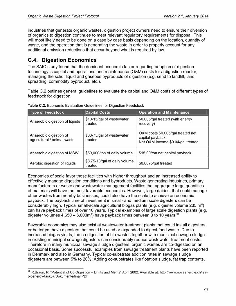
Organic Waste Digestion Project Protocol Version 2.1, January 2014
97
industries that generate organic wastes, digestion project owners need to ensure their diversion of organics to digestion continues to meet relevant regulatory requirements for disposal. This will most likely need to be done on a case by case basis depending on the location, quantity of waste, and the operation that is generating the waste in order to properly account for any additional emission reductions that occur beyond what is required by law.
C.4. Digestion Economics The SAIC study found that the dominant economic factor regarding adoption of digestion technology is capital and operations and maintenance (O&M) costs for a digestion reactor, managing the solid, liquid and gaseous byproducts of digestion (e.g. send to landfill, land spreading, commodity byproduct, etc.). Table C.2 outlines general guidelines to evaluate the capital and O&M costs of different types of feedstock for digestion. Table C.2. Economic Evaluation Guidelines for Digestion Feedstock
Type of Feedstock Capital Costs Operation and Maintenance
Anaerobic digestion of liquids $10-15/gal of wastewater treated
$0.005/gal treated (with energy recovery)
Anaerobic digestion of agricultural / animal waste
$60-75/gal of wastewater treated
O&M costs $0.006/gal treated net capital payback Net O&M Income $0.04/gal treated
Anaerobic digestion of MSW $50,000/ton of daily volume $15.00/ton net capital payback
Aerobic digestion of liquids $8.75-13/gal of daily volume treated $0.0075/gal treated
Economies of scale favor those facilities with higher throughput and an increased ability to effectively manage digestion conditions and byproducts. Waste generating industries, primary manufacturers or waste and wastewater management facilities that aggregate large quantities of materials will have the most favorable economics. However, large dairies, that could manage other wastes from nearby businesses, could also have the scale to achieve an economic payback. The payback time of investment in small- and medium scale digesters can be considerably high. Typical small-scale agricultural biogas plants (e.g. digester volume 235 m3) can have payback times of over 10 years. Typical examples of large scale digestion plants (e.g. digester volumes 4,650 – 6,000m3) have payback times between 3 to 10 years.58 Favorable economics may also exist at wastewater treatment plants that could install digesters or better yet have digesters that could be used or expanded to digest food waste. Due to increased biogas yields, the co-digestion of bio-wastes together with municipal sewage sludge in existing municipal sewage digesters can considerably reduce wastewater treatment costs. Therefore in many municipal sewage sludge digesters, organic wastes are co-digested on an occasional basis. Some successful examples from sewage treatment plants have been reported in Denmark and also in Germany. Typical co-substrate addition rates in sewage sludge digesters are between 5% to 20%. Adding co-substrates like flotation sludge, fat trap contents,
58 R.Braun, R. “Potential of Co-Digestion – Limits and Merits” April 2002. Available at: http://www.novaenergie.ch/iea-bioenergy-task37/Dokumente/final.PDF

Organic Waste Digestion Project Protocol Version 2.1, January 2014
98
food leftovers, etc., can considerably raise the biogas productivity of sewage sludge digesters by 40% to 230%. Nevertheless, if co-digestion is to be implemented into existing sewage treatment plants, depending on the bio-waste concentration and other factors, additional pre- and post-treatment equipment must be taken into consideration for the final cost calculation. For example, the cost and the logistical feasibility of cleaning (e.g. of plastic and other impurities) and grinding the materials so that they are suitable for the digester at the POTWs may be a major constraint in many cases. Table C.3 provides a general example of a dedicated MSW fed digester plant. Table C.3. Example Digester Plant, Payback Economics
Parameters Values
Digester volume 150,000 tons/year Main substrate MSW – Post-Consumer Food Waste Investment costs $15,000,000 Annual capital repayment costs $3,500,000 Other operating costs (year) $2,500,000 Total annual costs $6,000,000 Total revenue $9,056,000 Net income (before taxes) $3,056,000 Source: SAIC. The simple payback for this investment of $15 million is 4.9 years. If one considers the value of GHG credits (of avoided methane emissions from MSW being landfilled) estimated at between $1 and $1.5 million annually,59 the simple payback ranges from 3.2 years to 3.7 years. However, if the landfill is required to have methane controls, this reduces the methane emitted and therefore the value of GHG credits to $450,000 annually,60 increasing the payback to 4.3 years.
59 Based on EPA emissions factors for methane emissions from MSW in landfill (sourced from AP 42, Fifth Edition, Volume I Chapter 2: Solid Waste Disposal http://www.epa.gov/ttn/chief/ap42/ch02/index.html) and estimating carbon credit value at $8/ton (sourced from New Carbon Finance, Voluntary Market Research Note 13th January 2008 at www.newcarbonfinance.com/download.php?n=NCF_Voluntary_VCI_01_091.pdf&f=fileName&t=NCF_downloads). 60 Based on 70% methane control efficiency rate.

Organic Waste Digestion Project Protocol Version 2.1, January 2014
99
Appendix D Data Substitution This appendix provides guidance on calculating emission reductions when data integrity has been compromised due to missing data points. The methodologies presented below are to be used only for the methane concentration and flow metering parameters. The Reserve expects that projects will have continuous, uninterrupted data for the entire verification period. However, the Reserve recognizes that unexpected events or occurrences may result in brief data gaps. The following data substitution methodology may be used only for flow and methane concentration data gaps that are discrete, limited, non-chronic, and due to unforeseen circumstances. Data substitution can only be applied to methane concentration or flow readings, but not both simultaneously. If data is missing for both parameters, no reductions can be credited. Further, substitution may only occur when two other monitored parameters corroborate proper functioning of the destruction device and system operation within normal ranges. These two parameters must be demonstrated as follows:
1. Proper functioning can be evidenced by thermocouple readings for flares, energy output for engines, etc.
2. For methane concentration substitution, flow rates during the data gap must be consistent with normal operation.
3. For flow substitution, methane concentration rates during the data gap must be consistent with normal operations.
If corroborating parameters fail to demonstrate any of these requirements, no substitution may be employed. If the requirements above can be met, the following substitution methodology may be applied: Duration of Missing Data Substitution Methodology
Less than six hours Use the average of the four hours immediately before and following the outage
Six to 24 hours Use the 90% lower or upper confidence limit of the 24 hours prior to and after the outage, whichever results in greater conservativeness
One to seven days Use the 95% lower or upper confidence limit of the 72 hours prior to and after the outage, whichever results in greater conservativeness
Greater than one week No data may be substituted and no credits may be generated
Note: It is conservative to use the upper confidence limit when calculating emissions from the BCS (Equation 5.14); however, it is conservative to use the lower confidence limit when calculating the total amount of methane that is destroyed in the BCS (Equation 5.21).

Organic Waste Digestion Project Protocol Version 2.1, January 2014
100
Appendix E Example Project System Diagram

Compliance Offset Protocol Ozone Depleting
Substances Projects
Destruction of U.S. Ozone Depleting Substances Banks
Adopted: November 14, 2014
Note: All text is new. As permitted by title 2, California Code of Regulations, section 8, for ease of review, underline to indicate adoption has been omitted.
California Environmental Protection Agency
AIR RESOURCES BOARD

(This page left intentionally blank)

Table of Contents
Chapter 1. Purpose and Definitions .............................................................................................. 1
1.1. Purpose. ............................................................................................................................. 1 1.2. Definitions. .......................................................................................................................... 1
Chapter 2. Eligible Activities – Quantification Methodology .......................................................... 5 2.1. Eligible Destruction Facilities .............................................................................................. 6 2.2. Eligible ODS ....................................................................................................................... 6
2.2.1. Refrigerant Sources ..................................................................................................... 8 2.2.2. Foam Sources ............................................................................................................. 8
Chapter 3. Eligibility ...................................................................................................................... 9 3.1. General Eligibility Requirements ........................................................................................ 9 3.2. Location ............................................................................................................................ 10 3.3. Offset Project Operator or Authorized Project Designee .................................................. 10 3.4. Additionality ...................................................................................................................... 11
3.4.1. Legal Requirement Test ............................................................................................ 11 3.4.2. Performance Standard Evaluation ............................................................................. 11
3.5. Offset Project Commencement ........................................................................................ 12 3.6. Offset Project Reporting Period ........................................................................................ 12 3.7. Offset Project Crediting Period ......................................................................................... 12 3.8. Regulatory Compliance .................................................................................................... 12
Chapter 4. Offset Project Boundary – Quantification Methodology ............................................ 13 Chapter 5. Quantifying GHG Emission Reductions - Quantification Methodology ...................... 19
5.1. Quantifying Project Baseline Emissions ........................................................................... 20 5.2. Quantifying Project Emissions .......................................................................................... 22 5.3. Accounting for Disqualified ODS Material After Destruction............................................. 27 5.4. Conversion Factors and Rounding Practices ................................................................... 27
Chapter 6. Monitoring ................................................................................................................. 28 6.1. General Monitoring Requirements. .................................................................................. 28 6.2. Point of Origin Determination ........................................................................................... 30 6.3. Instrument QA/QC ............................................................................................................ 31 6.4. Document Retention ......................................................................................................... 31 6.5. Monitoring Parameters – Quantification Methodology ..................................................... 32 6.6. Other Monitoring Requirements – Quantification Methodology ........................................ 36
Chapter 7. Reporting ................................................................................................................... 36 7.1. Project Listing Requirements ........................................................................................... 37 7.2. Offset Project Data Report Requirements ........................................................................ 39
Chapter 8. Regulatory Verification Requirements ....................................................................... 40 Appendix A. Appliance Foam Recovery Efficiency and Calculations – Quantification
Methodology.......................................................................................................................... 41 Appendix B. Emission Factor Tables – Quantification Methodology .......................................... 44 Appendix C. ODS Mass and Composition from Building Foam Projects – Quantification
Methodology.......................................................................................................................... 49 Appendix D. ODS Mass and Composition from Refrigerant and Appliance Foam Projects –
Quantification Methodology ................................................................................................... 51

List of Tables Table 4.1. List of identified SSRs for refrigerant projects ……………………………………….…14 Table 4.2. List of identified SSRs for appliance foam projects ……………………………………16 Table 4.3. List of identified SSRs for building foam projects …...…………………………………18 Table 6.1. ODS Project Monitoring Parameters – Quantification Methodology ...……………… 33 Table B.1. Parameters for ODS Refrigerants ……………………………………...………………. 44 Table B.2. Parameters for ODS Foam ………………………………………………………...……. 44 Table B.3. ODS Carbon Ratio and Density ………………………………………………...………. 44 Table B.4. CO2 emissions per ton-mile-traveled ……………………………………………….…. 44 Table B.5. CO2 Emission Factors for Fossil Fuel Use ……………………………………………. 44 Table B.6. CO2 Electricity Emission Factors ………………………………………………………. 47 List of Figures Figure 4.1: Illustration of the Offset Project Boundary for Refrigerant Projects ………………… 13 Figure 4.2: Illustration of the Offset Project Boundary for Appliance Foam Projects ………….. 16 Figure 4.3: Illustration of the Offset Project Boundary for Building Foam Projects …………….. 18 Figure B.1. Map of eGRID2010 Subregions .……………………………………….…………..….. 48 List of Equations Equation 5.1. GHG Emission Reductions ……………………………………………………….…. 19 Equation 5.2. Total Project Baseline Emissions ...…………………………………………………. 20 Equation 5.3. Project Baseline Emissions from Refrigerant ODS .. ………………………….…. 20 Equation 5.4. Project Baseline Emissions from ODS Blowing Agent ...…………………………. 21 Equation 5.5. Total Project Emissions..…………………………………………………………...… 22 Equation 5.6. Project Emissions from the Use of Non-ODS Refrigerants ….…………………… 23 Equation 5.7. Calculating Project Emissions from the Release of ODS Blowing Agent during
Processing ……………………………………………………………………...……... 23 Equation 5.8. Project Emissions from Transportation and Destruction Using the Default
Emission Factors ……………………………………………………………………… 24 Equation 5.9. Project Emissions from the Destruction of ODS ..…………………………………. 25 Equation 5.10. Calculating Project Emissions from the Transportation of ODS ..……………… 26 Equation A.1. Initial Blowing Agent ..………………………………………………………………… 42 Equation A.2. Recovery Efficiency ………………………………………………………………… 43

1
Chapter 1. Purpose and Definitions
1.1. Purpose.
(a) The purpose of the Compliance Offset Protocol Ozone Depleting Substances
Projects (protocol) is to quantify greenhouse gas emission reductions associated
with the destruction of high global warming potential ozone depleting substances
sourced from and destroyed within the United States that would have otherwise
been released to the atmosphere. This project category includes ODS used in
both foam blowing agent and in refrigeration or air conditioning equipment.
(b) AB 32 exempts quantification methodologies from the Administrative Procedure
Act;1 however, those elements of the protocol are still regulatory. The exemption
allows future updates to the quantification methodologies to be made through a
public review and Board adoption process but without the need for rulemaking
documents. Each protocol identifies sections that are considered quantification
methodologies and exempt from APA requirements. Any changes to the non-
quantification elements of the offset protocols would be considered a regulatory
update subject to the full regulatory development process. Those sections that
are considered to be a quantification methodology are clearly indicated in the title
of the chapter or subchapter if only a portion of that chapter is considered part of
the quantification methodology of the protocol.
1.2. Definitions.
(a) For the purposes of this protocol, the following definitions apply:
(1) “Aggregation” means the grouping together of multiple containers of ODS
into a single shipment or single container. Aggregation does not require
the collected ODS to be combined into a single container. Multiple
containers shipped together are considered an aggregate.
(2) “Cap-and-Trade Regulation” or “Regulation” means ARB’s regulation
establishing the California Cap on Greenhouse Gas Emissions and
Market-Based Compliance Mechanisms set forth in title 17, California
1 Health and Safety Code section 38571
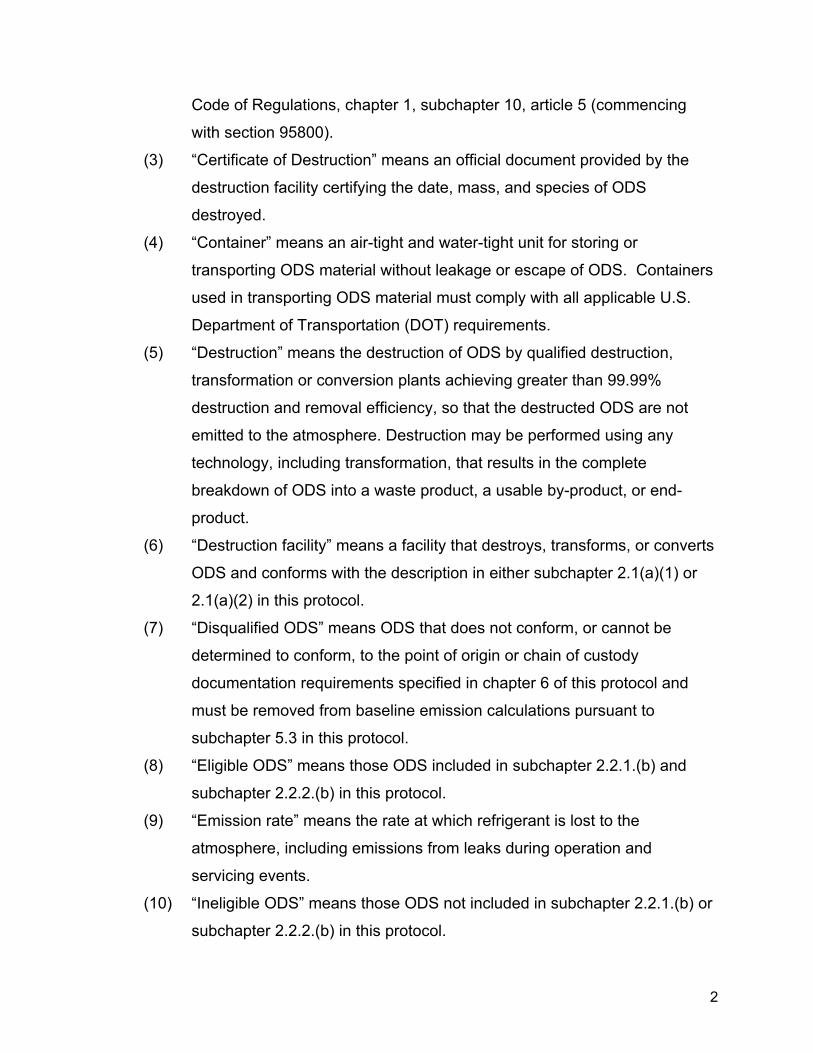
2
Code of Regulations, chapter 1, subchapter 10, article 5 (commencing
with section 95800).
(3) “Certificate of Destruction” means an official document provided by the
destruction facility certifying the date, mass, and species of ODS
destroyed.
(4) “Container” means an air-tight and water-tight unit for storing or
transporting ODS material without leakage or escape of ODS. Containers
used in transporting ODS material must comply with all applicable U.S.
Department of Transportation (DOT) requirements.
(5) “Destruction” means the destruction of ODS by qualified destruction,
transformation or conversion plants achieving greater than 99.99%
destruction and removal efficiency, so that the destructed ODS are not
emitted to the atmosphere. Destruction may be performed using any
technology, including transformation, that results in the complete
breakdown of ODS into a waste product, a usable by-product, or end-
product.
(6) “Destruction facility” means a facility that destroys, transforms, or converts
ODS and conforms with the description in either subchapter 2.1(a)(1) or
2.1(a)(2) in this protocol.
(7) “Disqualified ODS” means ODS that does not conform, or cannot be
determined to conform, to the point of origin or chain of custody
documentation requirements specified in chapter 6 of this protocol and
must be removed from baseline emission calculations pursuant to
subchapter 5.3 in this protocol.
(8) “Eligible ODS” means those ODS included in subchapter 2.2.1.(b) and
subchapter 2.2.2.(b) in this protocol.
(9) “Emission rate” means the rate at which refrigerant is lost to the
atmosphere, including emissions from leaks during operation and
servicing events.
(10) “Ineligible ODS” means those ODS not included in subchapter 2.2.1.(b) or
subchapter 2.2.2.(b) in this protocol.

3
(11) “Intermediate Aggregation Facility” means a transitional facility for eligible
ODS to be stored, aggregated, and processed in between a point of origin
and the destruction facility.
(12) “Mixed ODS” means less than or equal to 90% composition of a single
ODS species.
(13) “Non-mixed ODS” means greater than 90% composition of a single ODS
species.
(14) “Ozone Depleting Substances” or “ODS” means substances known to
deplete the stratospheric ozone layer. The ODS controlled under the
Montreal Protocol and its Amendments are chlorofluorocarbons (CFC),
hydrochlorofluorocarbons (HCFC), halons, methyl bromide (CH3Br),
carbon tetrachloride (CCl4), methyl chloroform (CH3CCl3),
hydrobromofluorocarbons (HBFC) and bromochloromethane (CHBrCl).
(15) “ODS blowing agent” means ODS entrained in insulation foam that was
used in manufacture of the foam to provide insulation, structural, and other
performance properties.
(16) “ODS species” means any individual type of ODS (e.g., CFC-11, CFC-
113, HCFC-22).
(17) “Recovery efficiency” means the percent of total ODS blowing agent that
is recovered during the process of ODS blowing agent extraction.
(18) “Refrigeration or air conditioning equipment” means a refrigeration or air
conditioning appliance or system used in any sector (including
commercial, industrial, or residential).
(19) “Registry offset credits” means the offset credits defined in section 95802
of the Regulation and whose issuance is described in section 95980 and
section 95980.1 of the Regulation.
(20) “Startup, shutdown, and malfunction plan” or “SSMP” means a plan, as
specified under 40 CFR 63.1206, that includes a description of potential
causes of malfunctions, including releases from emergency safety vents,
that may result in significant releases of hazardous air pollutants, and

4
actions the source is taking to minimize the frequency and severity of
those malfunctions.
(21) “Stockpile” means ODS stored for future use or disposal in bulk quantities
at a single facility. The ODS may be stored in multiple containers or a
single container.
(22) “Substitute refrigerant” means those refrigerants that will be used to fulfill
the function that would have been filled by the destroyed ODS
refrigerants. These refrigerants may be drop-in replacements used in
refrigeration or air conditioning equipment that previously used the ODS
species destroyed or may be used in new equipment that fulfills the same
market function.
(23) “Substitute emissions” means a term used in this protocol to describe the
GHG emitted from the use of substitute refrigerants in technologies that
are used to replace the ODS destroyed in a project.
(24) “Transformation” or “conversion” means the breakdown of a substance
into a waste product, a usable by-product, or end-product.
(b) For terms not defined in subchapter 1.2(a), the definitions in section 95802 of the
Regulation apply.
(c) Acronyms. For purposes of this protocol, the following acronyms apply:
(1) “AB 32” means the California Global Warming Solutions Act of 2006.
(2) "AHRI" means Air-Conditioning, Heating and Refrigeration Institute.
(3) “APA” means California’s Administrative Procedure Act.
(4) “ARB” means the California Air Resources Board.
(5) "CAA" means Clean Air Act.
(6) "CEMS" means continuous emissions monitoring system.
(7) "CFC" means chlorofluorocarbons.
(8) "CH4" means methane.
(9) “CITSS” means Compliance Instrument Tracking System Service.
(10) "CO2" means carbon dioxide.
(11) "CO2e" means carbon dioxide equivalent.
(12) "DOT" means U.S. Department of Transportation.

5
(13) "DRE" means destruction and removal efficiency.
(14) “GHG” means greenhouse gas.
(15) "GWP" means global warming potential.
(16) "HBFC" means hydrobromofluorocarbons.
(17) “HBR” means high boiling residue.
(18) "HCFC" means hydrochlorofluorocarbons.
(19) "HFC" means hydrofluorocarbons.
(20) "HWC" means hazardous waste combustor.
(21) “ID” means identification.
(22) “kg” means kilogram.
(23) “lb” means pound.
(24) “mt” means metric ton.
(25) “MWh” means megawatt hour.
(26) "NESHAP" means National Emissions Standards for Hazardous Air
Pollutants.
(27) “N2O” means nitrous oxide.
(28) "ODS" means ozone depleting substances.
(29) "PU" means polyurethane.
(30) “QA/QC” means quality assurance and quality control.
(31) "RCRA" means Resource Conservation and Recovery Act.
(32) “SSMP” means startup, shutdown, and malfunction plan.
(33) "SSR" means GHG sources, GHG sinks, and GHG reservoirs.
(34) "TEAP" means Technology & Economic Assessment Panel.
(35) “UN” means United Nations.
(36) “U.S.” means United States.
(37) “U.S. EPA” means United States Environmental Protection Agency.
Chapter 2. Eligible Activities – Quantification Methodology
This protocol defines a set of activities designed to reduce GHG emissions by the
destruction of eligible ODS at a single qualifying destruction facility.
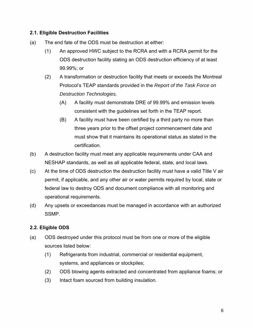
6
2.1. Eligible Destruction Facilities
(a) The end fate of the ODS must be destruction at either:
(1) An approved HWC subject to the RCRA and with a RCRA permit for the
ODS destruction facility stating an ODS destruction efficiency of at least
99.99%; or
(2) A transformation or destruction facility that meets or exceeds the Montreal
Protocol’s TEAP standards provided in the Report of the Task Force on
Destruction Technologies.
(A) A facility must demonstrate DRE of 99.99% and emission levels
consistent with the guidelines set forth in the TEAP report.
(B) A facility must have been certified by a third party no more than
three years prior to the offset project commencement date and
must show that it maintains its operational status as stated in the
certification.
(b) A destruction facility must meet any applicable requirements under CAA and
NESHAP standards, as well as all applicable federal, state, and local laws.
(c) At the time of ODS destruction the destruction facility must have a valid Title V air
permit, if applicable, and any other air or water permits required by local, state or
federal law to destroy ODS and document compliance with all monitoring and
operational requirements.
(d) Any upsets or exceedances must be managed in accordance with an authorized
SSMP.
2.2. Eligible ODS
(a) ODS destroyed under this protocol must be from one or more of the eligible
sources listed below:
(1) Refrigerants from industrial, commercial or residential equipment,
systems, and appliances or stockpiles;
(2) ODS blowing agents extracted and concentrated from appliance foams; or
(3) Intact foam sourced from building insulation.

7
(b) ODS refrigerants and ODS blowing agents extracted and concentrated from
appliance foams may not be combined within the same container.
(c) ODS produced or used as solvents, medical aerosols, or applications not listed
above are not eligible.
(d) A single offset project may incorporate ODS obtained from one or more of the
ODS source categories in subchapter 2.2(a).
(e) Destruction activity must take place under one or more Certificates of
Destruction.
(f) All of the following conditions must be met for multiple Certificates of Destruction
to be eligible as a single project:
(1) The Offset Project Operator and, if applicable, Authorized Project
Designee are the same for all ODS destroyed;
(2) All ODS destroyed must be at the same eligible destruction facility; and
(3) The destruction activities must occur during one reporting period.
(g) A Certificate of Destruction may be used for only one offset project.
(h) Each Certificate of Destruction must be issued by the qualifying destruction
facility and must include the following information:
(1) Offset Project Operator or Authorized Project Designee;
(2) Destruction facility;
(3) Certificate of destruction ID number;
(4) Serial, tracking, or ID number of all containers for which ODS destruction
occurred;
(5) Weight and type of material destroyed from each container; and
(6) Start and end destruction dates.
(i) The ODS destroyed may originate from a single source or from numerous
sources.
(j) The handling, recovery, and disposal of ODS refrigerants must be performed by
technicians certified by the U.S. EPA under CAA, sections 608 and 609, as
applicable. Technicians may only service refrigeration or air conditioning
equipment they are certified to service. Technician name and certification type(s)

8
must be retained as part of the documentation retention requirements of this
protocol and the Regulation.
2.2.1. Refrigerant Sources
(a) Eligible refrigerants must originate from domestic U.S. supplies. Imported
refrigerant is not eligible under this protocol.
(b) Only destruction of the following ODS refrigerants is eligible to generate ARB or
registry offset credits under this protocol:
(1) CFC-11;
(2) CFC-12;
(3) CFC-13;
(4) CFC-113;
(5) CFC-114; and
(6) CFC-115.
(c) ODS extracted from a foam source for use in refrigeration equipment is not part
of this source category and must be considered as a foam source.
(d) ODS sourced from federal government installations or stockpiles is not eligible
under this protocol.
2.2.2. Foam Sources
(a) Eligible ODS foam blowing agent must originate from U.S. foam sources.
Imported foams are not eligible under this protocol.
(b) Only the destruction of the following ODS foam blowing agents are eligible to
generate ARB or registry offset credits under this protocol:
(1) CFC-11;
(2) CFC-12;
(3) HCFC-22; and
(4) HCFC-141b.
(c) The only foam sources eligible under this protocol are building and appliance
insulation foams. Other sources, such as transport refrigeration units, are not
eligible.

9
(d) To be eligible to generate ARB or registry offset credits, the ODS blowing agent
must be destroyed in one of two ways:
(1) The ODS blowing agent must be extracted from the foam under negative
pressure and collected, stored, and transported in hermetically sealed
containers; or
(2) Intact foam must be separated from the building panels and must be
stored, transported, and destroyed in sealed containers.
Chapter 3. Eligibility
Ozone depleting substances offset projects must adhere to the eligibility requirements
below, in addition to the offset project eligibility criteria and regulatory program
requirements set forth in subarticle 13 of the Regulation.
3.1. General Eligibility Requirements
(a) Offset projects that use this protocol must:
(1) Collect and destroy ODS that would otherwise be emitted to the
atmosphere;
(2) Destroy the recovered ODS through an eligible end-use management
option pursuant to subchapter 2.1 of this protocol;
(3) Conform with the point of origin documentation requirements, as specified
in chapter 6 of this protocol; and
(4) Conform to the chain of custody documentation requirements, as specified
in chapter 6 of this protocol.
(b) An Offset Project Operator or Authorized Project Designee that uses this protocol
must:
(1) Provide the listing information required by section 95975 of the Regulation
and subchapter 7.1 of this protocol;
(2) Monitor SSRs within the GHG Assessment Boundary as delineated in
chapter 4 pursuant to the requirements of chapter 6 in this protocol;
(3) Quantify GHG emission reductions pursuant to chapter 5 of this protocol;

10
(4) Prepare and submit an Offset Project Data Report (OPDR) in accordance
with section 95976 of the Regulation and subchapter 7.2 of this protocol;
and
(5) Obtain offset verification services from an ARB-accredited offset
verification body in accordance with section 95977 of the Regulation and
chapter 8 of this protocol.
3.2. Location
(a) Only projects located in the United States or its territories are eligible under this
protocol.
(b) All ODS must be sourced from stocks in the United States or its territories.
(c) All ODS must be destroyed within the United States or its territories.
(d) Offset projects situated on the following categories of land are only eligible under
this protocol if they meet the requirements of this protocol and the Regulation,
including the waiver of sovereign immunity requirements of section 95975(l) of
the Regulation:
(1) Land that is owned by, or subject to an ownership or possessory interest
of a Tribe;
(2) Land that is “Indian lands” of a Tribe, as defined by 25 U.S.C. §81(a)(1); or
(3) Land that is owned by any person, entity, or Tribe, within the external
borders of such Indian lands.
3.3. Offset Project Operator or Authorized Project Designee
(a) The Offset Project Operator or Authorized Project Designee is responsible for
project listing, monitoring, reporting, and verification.
(b) The Offset Project Operator or Authorized Project Designee must submit the
information required by subarticle 13 of the Regulation and in chapter 7 of this
protocol.
(c) The Offset Project Operator must have legal authority to implement the offset
project.

11
3.4. Additionality
Offset projects must meet the additionality requirements of section 95973(a)(2) of the
Regulation, in addition to the requirements in this protocol. Eligible offsets must be
generated by projects that yield additional GHG reductions that exceed any GHG
reductions otherwise required by law or regulation or any GHG reduction that would
otherwise occur in a conservative business-as-usual scenario. These requirements are
assessed through the Legal Requirement Test in subchapter 3.4.1 and the Performance
Standard Evaluation in subchapter 3.4.2 of this protocol.
3.4.1. Legal Requirement Test
(a) Emission reductions achieved by a project using this protocol must exceed those
required by any law, regulation, or legally binding mandate, as required in
sections 95973(a)(2)(A) and 95975(n) of the Regulation.
(b) The following legal requirement test applies to all ODS projects:
(1) If no law, regulation, or legally binding mandate requires the destruction of
ODS stocks, all emission reductions resulting from the recovery and
destruction of ODS are considered to not be legally required, and
therefore eligible for crediting under this protocol.
(2) If any law, regulation, or legally binding mandate requires the destruction
of ODS stocks, only emission reductions resulting from the recovery and
destruction of ODS that are in excess of what is required to comply with
those laws, regulations, and legally binding mandates are eligible for
crediting under this protocol.
3.4.2. Performance Standard Evaluation
(a) Emission reductions achieved by a project using this protocol must exceed those
likely to occur in a conservative business-as-usual scenario.
(b) The destruction of ODS sourced from the U.S. government is ineligible for
crediting under this protocol.
(c) The performance standard evaluation is satisfied if the ODS project activities
meet the project definition and all other eligibility requirements in the protocol.

12
3.5. Offset Project Commencement
(a) For this protocol, offset project commencement is defined as the date on which
the earliest destruction activity of a project commences, as documented on a
Certificate of Destruction.
(b) Offset project activities will occur prior to offset project commencement.
(c) Pursuant to section 95973(a)(2)(B) of the Regulation, compliance offset projects
must have an offset project commencement date after December 31, 2006.
3.6. Offset Project Reporting Period
(a) An ODS project can only have a single reporting period.
(b) Multiple destruction events may be combined within a single reporting period
subject to the requirements in subchapter 2.2.(e) of this protocol.
(c) The reporting period must not exceed 12 consecutive months. The Offset
Project Operator or Authorized Project Designee may choose a reporting period
shorter than 12 consecutive months.
(d) The offset project reporting period begins on the offset project commencement
date.
3.7. Offset Project Crediting Period
(a) The offset project crediting period is the period of time over which emission
reductions are quantified for the purpose of determining creditable GHG
reductions.
(b) The offset project crediting period for this protocol is ten years.
(c) The offset project crediting period begins on the offset project commencement
date.
3.8. Regulatory Compliance
(a) An offset project must meet the regulatory compliance requirements set forth in
section 95973(b) of the Regulation.
(b) The regulatory compliance requirements for a project apply to the collection,
recovery, storage, transportation, mixing, and destruction of ODS, including
disposal of the associated post-destruction waste products. The regulatory

13
compliance requirements extend to the destruction facility during the time ODS
destruction occurs.
Chapter 4. Offset Project Boundary – Quantification Methodology
(a) The GHG assessment boundary, or offset project boundary, delineates the SSRs
that must be included or excluded when quantifying the net changes in emissions
associated with the recovery and destruction ODS.
(b) Figure 4.1 illustrates the GHG assessment boundary for refrigerant ODS
projects.
(1) All SSRs within the bold line are included and must be accounted for
under this protocol.
(2) SSRs in lightly shaded boxes are relevant to the baseline and project
emissions.
(3) SSRs in darkly shaded boxes are relevant only to project emissions.
Figure 4.1: Illustration of the Offset Project Boundary for Refrigerant Projects
(c) Table 4.1 lists the SSRs for refrigerant projects indicating which gases are
included or excluded from the offset project boundary.
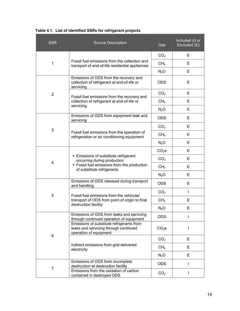
14
Table 4.1. List of identified SSRs for refrigerant projects
SSR Source Description Gas
Included (I) or Excluded (E)
1 Fossil fuel emissions from the collection and transport of end-of-life residential appliances
CO2 E
CH4 E
N2O E
2
Emissions of ODS from the recovery and collection of refrigerant at end-of-life or servicing
ODS E
Fossil fuel emissions from the recovery and collection of refrigerant at end-of-life or servicing
CO2 E
CH4 E
N2O E
3
Emissions of ODS from equipment leak and servicing ODS E
Fossil fuel emissions from the operation of refrigeration or air conditioning equipment
CO2 E
CH4 E
N2O E
4
Emissions of substitute refrigerant occurring during production
Fossil fuel emissions from the production of substitute refrigerants
CO2e E
CO2 E
CH4 E
N2O E
5
Emissions of ODS released during transport and handling ODS E
Fossil fuel emissions from the vehicular transport of ODS from point of origin to final destruction facility
CO2 I
CH4 E
N2O E
6
Emissions of ODS from leaks and servicing through continued operation of equipment ODS I
Emissions of substitute refrigerants from leaks and servicing through continued operation of equipment
CO2e I
Indirect emissions from grid-delivered electricity
CO2 E
CH4 E
N2O E
7
Emissions of ODS from incomplete destruction at destruction facility ODS I
Emissions from the oxidation of carbon contained in destroyed ODS CO2 I

15
SSR Source Description Gas
Included (I) or Excluded (E)
Fossil fuel emissions from the destruction of ODS at destruction facility
CO2 I
CH4 E
N2O E
Indirect emissions from the use of grid-delivered electricity
CO2 I
CH4 E
N2O E
(d) Figure 4.2 illustrates the GHG assessment boundary for appliance foam blowing
agent recovery ODS projects.
(1) All SSRs within the bold line are included and must be accounted for
under this protocol.
(2) SSRs in unshaded boxes are relevant only to baseline emissions.
(3) SSRs in lightly shaded boxes are relevant to the baseline and project
emissions.
(4) SSRs in darkly shaded boxes are relevant only to project emissions.

16
Figure 4.2: Illustration of the Offset Project Boundary for Appliance Foam Projects
(e) Table 4.2 lists the SSRs for appliance foam projects indicating which gases are
included or excluded from the offset project boundary. Table 4.2. List of identified SSRs for appliance foam projects
SSR Source Description Gas
Included (I) or Excluded (E)
1 Fossil fuel emissions from the collection and transport of end-of-life residential appliances
CO2 E
CH4 E
N2O E
5
Emissions of ODS released during transport and handling ODS E
Fossil fuel emissions from the vehicular transport of ODS from point of origin to final destruction facility
CO2 I
CH4 E
N2O E
7 Emissions of ODS from incomplete destruction at destruction facility ODS I
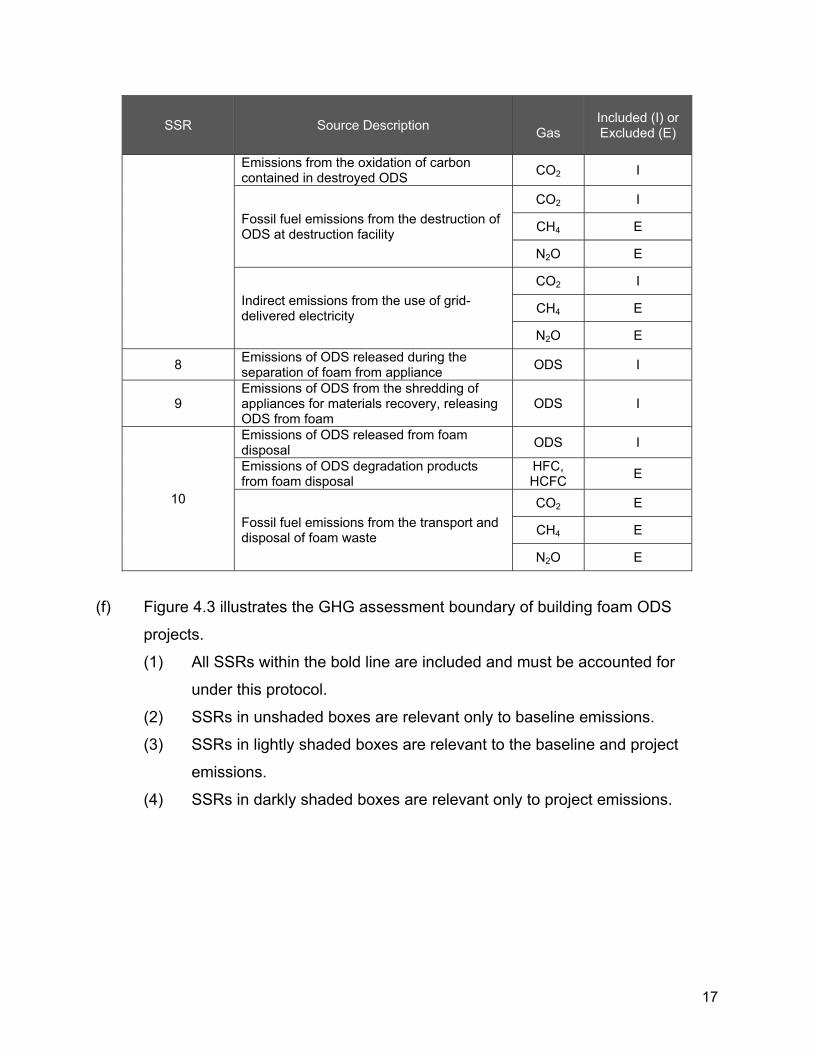
17
SSR Source Description Gas
Included (I) or Excluded (E)
Emissions from the oxidation of carbon contained in destroyed ODS CO2 I
Fossil fuel emissions from the destruction of ODS at destruction facility
CO2 I
CH4 E
N2O E
Indirect emissions from the use of grid-delivered electricity
CO2 I
CH4 E
N2O E
8 Emissions of ODS released during the separation of foam from appliance ODS I
9 Emissions of ODS from the shredding of appliances for materials recovery, releasing ODS from foam
ODS I
10
Emissions of ODS released from foam disposal ODS I
Emissions of ODS degradation products from foam disposal
HFC, HCFC E
Fossil fuel emissions from the transport and disposal of foam waste
CO2 E
CH4 E
N2O E
(f) Figure 4.3 illustrates the GHG assessment boundary of building foam ODS
projects.
(1) All SSRs within the bold line are included and must be accounted for
under this protocol.
(2) SSRs in unshaded boxes are relevant only to baseline emissions.
(3) SSRs in lightly shaded boxes are relevant to the baseline and project
emissions.
(4) SSRs in darkly shaded boxes are relevant only to project emissions.

18
Figure 4.3: Illustration of the Offset Project Boundary for Building Foam Projects
(g) Table 4.3 lists the SSRs for building foam projects indicating which gases are
included or excluded from the offset project boundary.
Table 4.3. List of identified SSRs for building foam projects
SSR Source Description Gas
Included (I) or Excluded (E)
5
Emissions of ODS released during transport and handling ODS E
Fossil fuel emissions from the vehicular transport of ODS from point of origin to final destruction facility
CO2 I
CH4 E
N2O E
7
Emissions of ODS from incomplete destruction at destruction facility ODS I
Emissions from the oxidation of carbon contained in destroyed ODS CO2 I
Fossil fuel emissions from the destruction of ODS at destruction facility
CO2 I
CH4 E
N2O E
Indirect emissions from the use of grid-delivered electricity
CO2 I
CH4 E
N2O E
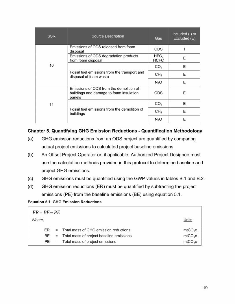
19
SSR Source Description Gas
Included (I) or Excluded (E)
10
Emissions of ODS released from foam disposal ODS I
Emissions of ODS degradation products from foam disposal
HFC, HCFC E
Fossil fuel emissions from the transport and disposal of foam waste
CO2 E
CH4 E
N2O E
11
Emissions of ODS from the demolition of buildings and damage to foam insulation panels
ODS E
Fossil fuel emissions from the demolition of buildings
CO2 E
CH4 E
N2O E
Chapter 5. Quantifying GHG Emission Reductions - Quantification Methodology (a) GHG emission reductions from an ODS project are quantified by comparing
actual project emissions to calculated project baseline emissions.
(b) An Offset Project Operator or, if applicable, Authorized Project Designee must
use the calculation methods provided in this protocol to determine baseline and
project GHG emissions.
(c) GHG emissions must be quantified using the GWP values in tables B.1 and B.2.
(d) GHG emission reductions (ER) must be quantified by subtracting the project
emissions (PE) from the baseline emissions (BE) using equation 5.1. Equation 5.1. GHG Emission Reductions
PEBEER
Where,
Units
ER = Total mass of GHG emission reductions mtCO2e BE = Total mass of project baseline emissions mtCO2e PE = Total mass of project emissions mtCO2e

20
5.1. Quantifying Project Baseline Emissions (a) Baseline emissions (BE) must be estimated by using equation 5.2 and by
summing the baseline emissions for all SSRs identified as included in the
baseline in tables 4.1, 4.2, and 4.3.
Equation 5.2. Total Project Baseline Emissions
(b) Baseline emissions from refrigerant ODS (BErefr) must be quantified using
equation 5.3.
(c) BErefr must include the estimated CO2e emissions that would have occurred over
the ten-year crediting period had the destroyed ODS been used in existing
refrigeration or air conditioning equipment.
(d) The total mass of refrigerant ODS sent for destruction (Qrefr,i) includes eligible
ODS and excludes the mass of HBR, moisture, ineligible ODS, and other
ineligible material.
(e) The GWP values for refrigerant ODS (GWPi) must be taken from table B.1.
(f) The 10-year cumulative emission rate for refrigerant ODS (ERrefr,i) must be taken
from table B.1.
(g) If the project did not destroy any refrigerant ODS, then BErefr = 0. Equation 5.3. Project Baseline Emissions from Refrigerant ODS
foamrefr BEBEBE
Where,
Units
BE = Total mass of project baseline emissions mtCO2e BErefr = Total mass of project baseline emissions from refrigerant ODS mtCO2e
BEfoam = Total mass of project baseline emissions from ODS blowing agent mtCO2e
i
iirefrirefrrefr GWPERQBE ,,
Where,
Units
BErefr = Total mass of refrigerant project baseline emissions mtCO2e Qrefr,i = Total mass of refrigerant ODS i sent for destruction by the offset
project mtODS
ERrefr,i = 10-year cumulative emission rate of refrigerant ODS i from table B.1
%

21
(h) Baseline emissions from foam ODS (BEfoam) must be quantified using equation
5.4.
(i) BEfoam must include the estimated CO2e emissions that would have occurred
over ten years as the result of foam disposal.
(j) The GWP values for refrigerant ODS (GWPi) must be taken from table B.2.
(k) The 10-year cumulative emission rate for appliance and building ODS (ERi,app, ERi,build) must be taken from table B.2.
(l) The mass of the recovered and concentrated ODS blowing agent (Qrecover) from
appliance foam must be calculated according to the procedures in appendix D.
(m) The recovery efficiency (RE) of appliance foam ODS blowing agent must be
calculated according to equation A.2.
(n) The weight of intact building foam (Qfoam) must be calculated on the scales of the
eligible destruction facility as specified in appendix C.
(o) The mass fraction of ODS blowing agent in building foam (BA%) must be
calculated according to appendix C.
(p) If the project did not destroy any foam ODS, then BEfoam = 0.
Equation 5.4. Project Baseline Emissions from ODS Blowing Agent
GWPi = The GWP value for ODS i from table B.1 mtCO2e/ mtODS
i
ibuildibuildiappiappifoam GWPERBAERBABE ,,,,
Where,
Units
BEfoam = Total mass of ODS blowing agent project baseline emissions mtCO2e BAapp,i, = Total mass of ODS blowing agent i from appliance foam prior to
treatment or processing, including blowing agent lost during processing
mtODS
BAbuild,i = Total mass of ODS blowing agent i from building foam sent for destruction
mtODS
ERi,app = 10-year emission rate of appliance ODS blowing agent i at end-of-life from table B.2
%
ERi,build = 10-year emission rate of building ODS blowing agent i at end-of-life from table B.2
%
GWPi = The GWP value for ODS i from table B.2 mtCO2e/ mtODS

22
5.2. Quantifying Project Emissions (a) Project emissions (PE) must be quantified by summing the emissions for all
SSRs identified as included in the project in table 4.1 using equation 5.5.
Equation 5.5. Total Project Emissions
2 RE does not extend to the ODS destruction efficiency, which is handled separately under this protocol.
RE
REQQBA erreerreiapp
1covcov,
Where,
Units
BAapp,i = Total mass of ODS foam blowing agent in foam prior to treatment or processing, including ODS foam blowing agent lost during processing
mtODS
Qrecover = Total mass of ODS foam blowing agent recovered during processing and sent for destruction, as determined according to appendix D
mtODS
RE = Recovery efficiency of the ODS foam blowing agent recovery process2 from equation A.2 (in appendix A)
%
%BAQBA foambuild
Where,
BAbuild = Total mass of ODS blowing agent i from building foam sent for destruction
mtODS
Qfoam = Total mass of foam with entrained ODS blowing agent sent for destruction
mt
BA% = Mass fraction of ODS blowing agent entrained in building foam, as determined according to appendix C
fraction (0-1)
DestTrBASubPE prref
Where,
Units
PE = Total mass of project emissions mtCO2e Subref = Total GHG emissions from substitute refrigerant mtCO2e
BApr = Total mass of ODS blowing agent from appliance foam released during ODS extraction
mtCO2e
Tr = Total GHG emissions from transportation of ODS (calculated using either the default value in equation 5.8 or equation 5.10)
mtCO2e
Dest = Total GHG emissions from the process associated with destruction of ODS
mtCO2e

23
(b) Project emissions from substitute refrigerants (Subref) must be quantified using
equation 5.6.
(c) Subref must include the estimated CO2e emissions over a ten-year period from
non-ODS substitute refrigerants that are used in their place. The emission
factors for substitute refrigerants in table B.1 must be used.
(d) The total mass of refrigerant ODS sent for destruction (Qrefi) excludes the mass
of HBR, moisture, and ineligible ODS.
(e) If the project did not destroy any refrigerant, then Subref = 0. Equation 5.6. Project Emissions from the Use of Non-ODS Refrigerants
(f) Project emissions from the release of ODS foam blowing agent during recovery
from appliance foam (BApr) must be quantified using equation 5.7.
(g) The recovery efficiency (RE) of appliance foam ODS blowing agent must be
calculated according to equation A.2.
(h) The mass of the recovered and concentrated ODS blowing agent (Qrecover) from
appliance foam must be calculated according to the procedures in appendix D.
(i) If the project did not destroy any foam ODS, then BApr = 0. Equation 5.7. Calculating Project Emissions from the Release of ODS Blowing Agent during Processing
i
iirefr SEQrefSub
Where,
Units
Subrefr = Total mass of project emissions from substitute refrigerants mtCO2e Qref i = Total mass of refrigerant i sent for destruction mt
SEi = Emission factor for substitute(s) for refrigerant i, from table B.1 mtCO2e/ mtODS destroyed
i
iiapppr GWPREBABA 1,
Where,
Units
BApr = Total mass of ODS blowing agent from appliance foam released during ODS extraction
mtCO2e
BAapp,i = Total mass of appliance ODS foam blowing agent in foam prior to treatment or processing, including ODS foam blowing agent lost
mtODS

24
(j) Project emission from the transportation and destruction of ODS may be
quantified using default emission factors in equation 5.8.
(1) The default emission factor for ODS transportation and destruction (EFT&D)
is 7.5 metric tons CO2e per metric ton ODS for refrigerant or extracted
ODS blowing agent projects.
(2) The default emission factor for ODS transportation and destruction
(EFT&D) is 75 metric tons CO2e per metric ton ODS for intact building foam
projects.
(3) QTotalODS includes the mass of all eligible and ineligible ODS, moisture,
HBR, and other accompanying material.
Equation 5.8. Project Emissions from Transportation and Destruction Using the Default Emission Factors
3 RE does not extend to the ODS destruction efficiency, which is handled separately under this protocol.
during processing equation 5.4 RE = Recovery efficiency of the ODS foam blowing agent recovery
process from equation A.2 %
GWPi = GWP of ODS i from table B.2 mtCO2e/ mtODS
RE
REQQBA erreerreiapp
1covcov,
Where,
Units
BAapp,i = Total mass of ODS foam blowing agent in foam prior to treatment or processing, including ODS foam blowing agent lost during processing
mtODS
Qrecover = Total mass of ODS foam blowing agent recovered during processing and sent for destruction, as determined according to appendix D
mtODS
RE = Recovery efficiency of the ODS foam blowing agent recovery process3 from equation A.2
%
i
DTTotalODS EFQDestTr &
Where,
Units
Tr+Dest = Total GHG emissions from ODS transportation and destruction, as calculated using default emission factors
mtCO2e

25
(k) If the transportation and destruction are not quantified using the default factors in
equation 5.8, then equation 5.9 must be used to quantify site-specific ODS
destruction emission (Dest), and equation 5.10 must be used to quantify ODS
transportation emissions (Tr).
(l) In both equation 5.9 and equation 5.10, Qdestroy is the total mass sent for
destruction including HBR, moisture, ineligible ODS, and other ineligible material.
Equation 5.9. Project Emissions from the Destruction of ODS
QTotalODS, = Total mass of ODS i sent for destruction in the project mtODS EFT&D = Default emission factor for transportation and destruction of ODS
(7.5 for refrigerant or extracted ODS blowing agent projects, 75 for intact building foam projects)
mtCO2e/ mtODS
2COemissionsdestdest ODSODSELFFDest
Where,
Units
Dest = Total GHG emissions from the destruction of ODS mtCO2e FFdest = Total GHG emissions from fossil fuel used in the destruction
facility mtCO2
ELdest = Total indirect GHG emissions from grid electricity used at the destruction facility
mtCO2
ODSemissions = Total GHG emissions of undestroyed ODS mtCO2e ODSCO2 = Total GHG emissions of CO2 from ODS oxidation mtCO2
With:
1000
,, k
kFFkPR
dest
EFFFFF
Where,
Units
FFdest = Total carbon dioxide emissions from the destruction of fossil fuel used to destroy ODS
mtCO2
FFPR,k = Total fossil fuel k used to destroy ODS unit of fossil fuel
EFFF,k = Fuel specific emission factor from table B.5 kg CO2/ unit fossil fuel
1000 = Conversion of kg to metric tons kgCO2/ mtCO2
And:
62.2204
ELPRdest
EFELEL

26
(m) A ton-mile is (TMTi) is the product of the distance travelled in miles and the mass
of ODS, any accompanying materials, and containers transported in metric tons.
(n) Emissions shall be calculated for each leg of the transportation process
separately and then summed according to equation 5.10. Equation 5.10. Calculating Project Emissions from the Transportation of ODS
Where,
Units
ELdest = Total carbon dioxide emissions from the consumption of electricity from the grid used to destroy ODS
mtCO2
ELPR = Total electricity consumed to destroy ODS MWh EFEL = Carbon emission factor for electricity used from table B.6 lb CO2/
MWh And:
i
iidestroyemissions GWPQODS 0001.0,
Where,
Units
ODSemissions = Total GHG emissions of undestroyed ODS mtCO2e Qdestroy,i = Total mass of ODS i sent for destruction in the project mtODS 0.0001 = Maximum allowable percent of ODS fed to destruction that is not
destroyed
GWPi = The GWP value for ODSi from table B.1 mtCO2e/ mtODS
And:
i
iidestroyCO CRQODS 667.39999.0,2
ODSCO2 = Total GHG emissions of CO2 from ODS oxidation mtCO2 Qdestroy,i = Total mass of ODS i sent for destruction in the project mtODS 0.9999 = Minimum destruction efficiency of destruction facility
CRi = Carbon ratio of ODS i from table B.3 mole C/ mole ODS
3.667 = Ratio of CO2 to C
i
TMTi EFTMTTr
1000
Where, Units
Tr = Total GHG emissions from transportation of ODS mtCO2e TMTi = Ton-miles-traveled for ODS i destroyed mt-miles
EFTMT = CO2 emissions per mt-mile-traveled from table B.4
kgCO2 / mt-mile

27
5.3. Accounting for Disqualified ODS Material After Destruction ARB or registry offset credits may only be generated for the destruction of eligible ODS
that meet the point of origin and chain of custody requirements specified in chapter 6 of
this protocol. Any disqualified ODS must be removed from baseline emission
calculations using the following method to determine the weight and ODS species of the
disqualified ODS:
(a) The total weight of each container of disqualified ODS shall be considered as the
container’s full capacity when the ODS is acquired. Documentation of the
acquired ODS must identify the capacity of the disqualified ODS container or the
entire destruction event is not eligible for crediting. If a container’s capacity is
labelled in volume rather than in weight, the ODS densities in table B.3 must be
used to convert the volume to weight. If converting between mass and volume,
the ODS must be in a liquid state.
(b) The species of each disqualified ODS shall be the species with the highest GWP
of the destruction event.
(c) The determined weight of disqualified ODS shall be subtracted from the total
mass of that ODS species destroyed in the project.
(1) The total mass of refrigerant ODS sent for destruction (Qrefr,i) shall be
adjusted in equation 5.3.
(2) The total mass of ODS foam blowing agent in foam prior to treatment or
processing, including ODS foam blowing agent lost during processing
(BAapp,i) shall be adjusted in equation 5.4.
(3) The total mass of ODS blowing agent from building foam sent for
destruction (BAbuild,i) shall be adjusted in equation 5.4.
5.4. Conversion Factors and Rounding Practices (a) For the purpose of this protocol, 1 pound (lb) equals 0.45359 kilogram (Kg).
(b) The following rounding practices shall be applied for the purpose of this protocol:
(1) At least five significant figures shall be maintained.
(2) There shall be no rounding to the left side of the decimal.
1000 = Conversion from kg to mt kg/mt

28
Chapter 6. Monitoring 6.1. General Monitoring Requirements. (a) The Offset Project Operator or, if applicable, the Authorized Project Designee is
responsible for monitoring all project activities to ensure compliance with the
requirements of the Regulation and this protocol.
(b) The point of origin of all ODS must be documented. To be eligible to receive
ARB offset credits or registry offset credits, the Offset Project Operator or, if
applicable, the Authorized Project Designee must collect and maintain
documentation showing regulatory compliance back to all points of origin.
(c) Documentation of the point of origin must be generated at the time of collection
from the point of origin and must include all of the following:
(1) Facility name and physical address;
(2) Point of origin zip code;
(3) Identification of any refrigeration or air conditioning equipment by serial
number, if available, or description, location, and function, if serial number
is unavailable (for quantities greater than 500 pounds); and
(4) Serial or ID number of containers used for storage and transport.
(d) The Offset Project Operator or, if applicable, Authorized Project Designee must
collect and maintain documentation on the chain of custody and ownership of the
ODS beginning at the point of origin until destruction, including all of the
following:
(1) Names, addresses, and contact information of all entities buying and
selling ODS for destruction; and
(2) The mass of ODS, including ineligible ODS and contaminants, at each
transaction.
(e) The Offset Project Operator or, if applicable, the Authorized Project Designee
must collect and maintain all of the following information:
(1) For building foams:
(A) Building address;
(B) Date of construction;
(C) Blowing agent used; and

29
(D) Approximate building dimensions.
(2) For ODS blowing agent recovered from appliance foam:
(A) Number of appliances processed;
(B) Facility at which ODS foam blowing agent is extracted to
concentrated form; and
(C) Facility at which appliance de-manufacture occurs, if applicable.
(f) For ODS refrigerant and concentrated ODS foam blowing agent, the Offset
Project Operator or, if applicable, the Authorized Project Designee must collect
and maintain all of the following information from the composition and mass
analysis:
(1) Time and date of sample;
(2) Name of Offset Project Operator or Authorized Project Designee;
(3) Name of technician taking sample;
(4) Employer of technician taking sample;
(5) Volume of container from which sample was extracted;
(6) Ambient air temperature at time of sampling; and
(7) Chain of custody for each sample from the point of sampling to the AHRI
lab.
(g) The destruction facility must track continuously during the ODS destruction
process the following parameters and provide the data about these parameters
to the Offset Project Operator or, if applicable, Authorized Project Designee. The
Offset Project Operator or, if applicable, the Authorized Project Designee must
collect and maintain all of the following information from the destruction facility:
(1) The ODS feed rate;
(2) The amount and type of consumables used in the process (not required if
default project emission factor for transportation and destruction is used);
(3) The amount of electricity and amount and type of fuel consumed by the
destruction unit (not required if default project emission factor for
transportation and destruction is used);
(4) Operating temperature and pressure of the destruction unit during ODS
destruction;

30
(5) Effluent discharges measured in terms of water and pH levels; and
(6) CEMS data on the emissions of carbon monoxide during ODS destruction.
6.2. Point of Origin Determination (a) The Offset Project Operator or, if applicable, Authorized Project Designee must
collect and maintain data on the point of origin of each quantity of ODS as part of
tracking chain of custody. Data must be generated at the time of collection from
the point of origin.
(b) Point of origin is defined as follows:
(1) For refrigerant ODS which is stored within a stockpile more than 24
months prior to acquisition by the Offset Project Operator:
(A) The point of origin for refrigerant ODS which became part of the
stockpile before January 1, 2015 is the location of the stockpile.
(B) The point of origin for refrigerant ODS which became part of the
stockpile after December 31, 2014, is the site at which greater than
or equal to 500 pounds of ODS is first aggregated into a single or
multiple containers after December 31, 2014. The point of origin
may be the location of the stockpile or a site prior to the ODS
becoming part of the stockpile.
(2) For refrigerant ODS which is not part of a stockpile for at least 24 months
prior to acquisition by the Offset Project Operator:
(A) The point of origin for refrigerant ODS with mass less than 500
pounds is the site at which greater than or equal to 500 pounds of
ODS is aggregated.
(B) The point of origin for refrigerant ODS with mass greater than or
equal to 500 pounds is the site where the ODS is removed from
service.
(3) For ODS blowing agent extracted from appliance foam, the point of origin
is the facility where the ODS is extracted.
(4) For ODS blowing agent in building foam, the point of origin is the location
from which the building foam was taken.

31
(c) For refrigerant ODS, the following provisions also apply to point of origin
determination:
(1) Any location at which 500 pounds is reached in a single transaction or
shipment is a point of origin; the 500 pounds does not need to be in a
single container.
(2) For each container included within the project, the mass of HBR, moisture,
ineligible ODS, and other ineligible material shall be included to determine
if the 500 pound threshold is reached.
(3) If refrigeration or air conditioning equipment containing at least 500
pounds of ODS is transported prior to the ODS being removed from the
equipment, then the point of origin is the site at which the refrigeration or
air conditioning equipment was last in service.
(4) When ODS is added to a single container which is part of a stockpile and
a portion of the ODS is subsequently removed from the container, the
ODS removed must be considered the ODS stored the longest (i.e., first-
in, first-out method).
6.3. Instrument QA/QC (a) Scales used to determine the mass of ODS used in calculating emission
reductions must be inspected at least quarterly.
(b) The scales must be properly calibrated per the destruction facility’s RCRA permit,
or for non-RCRA facilities calibrated at least quarterly to an accuracy of within
5% of reading. RCRA facilities that do not have calibration requirements defined
in their RCRA permits must calibrate scales quarterly to an accuracy of within 5%
of reading.
6.4. Document Retention (a) The Offset Project Operator or, if applicable, Authorized Project Designee is
required to keep all documentation and information outlined in the Regulation
and this protocol. Record retention requirements are set forth in section 95976 of
the Regulation.

32
(b) Information that must be retained by the Offset Project Operator or Authorized
Project Designee includes:
(1) All data inputs for the calculation of the offset project emission reductions,
including all required sampled data;
(2) Copies of all permits, Notices of Violations (NOVs), and any relevant
administrative or legal consent orders dating back at least 3 years prior to
the project commencement date;
(3) Destruction facility monitoring information (CEMS data, DRE
documentation, scale readings, calibration procedures, and permits);
(4) Chain of custody and point of origin documentation; and
(5) ODS composition and mass lab reports.
6.5. Monitoring Parameters – Quantification Methodology The Offset Project Operator or, if applicable, Authorized Project Designee must monitor
the parameters described in table 6.1.

33
Table 6.1. ODS Project Monitoring Parameters – Quantification Methodology
Eq. # Parameter Description Data Unit Measurement Frequency
Calculated (c)Measured (m)Reference (r)
Operating records (o)
Comment
Legal Requirement Test N/A For each offset project Must be monitored and determined
for each project
Mass of ODS (or ODS mixture) in each container
mass of mixture Per container m Must be determined for each
container
Mixture of ODS species in each container
mass ODS/ mass of mixture
Per container m Must be determined for each container
5.1 ERt Total mass of GHG emission reductions during the reporting period
tCO2e For each offset project c
5.1, 5.2 BEt Total mass of project baseline emissions during the reporting period
tCO2e For each offset project c
5.1, 5.5 PEt Total mass of project emissions during the reporting period
tCO2e For each offset project c
5.2, 5.3 BErefr Total mass of project baseline emissions from refrigerant ODS
tCO2e For each offset project c
5.2, 5.4 BEfoam Total mass of project baseline emissions from ODS blowing agent
tCO2e For each offset project c
5.3, 5.6 Qrefr,i Total mass of refrigerant ODS i sent for destruction tODS For each offset
project m
5.3 ERrefr,i 10-year cumulative emission rate of refrigerant ODS i 0 - 1.0 N/A r See table B.1
5.3, 5.4, 5.7, 5.10 GWPi GWP of ODS i tCO2e/ tODS N/A r See table B.1
5.4, 5.7 BAapp,i,
Total mass of ODS blowing agent i from appliance foam prior to treatment or processing, including blowing agent lost during processing
tODS For each offset project c

34
Eq. # Parameter Description Data Unit Measurement Frequency
Calculated (c)Measured (m)Reference (r)
Operating records (o)
Comment
5.4 BAbuild,i Total mass of ODS blowing agent i from building foam sent for destruction.
tODS For each offset project c
5.4 ERi,j
Lifetime emission rate of ODS blowing agent i from application j at end-of-life (see table B.1)
% (0-1) N/A r
5.4 Qrecover
Total mass of ODS foam blowing agent recovered during processing and sent for destruction
tODS For each offset project m
5.4, 5.7 RE Recovery efficiency of the ODS foam blowing agent recovery process
% (0-1) Once for each offset project c See appendix A.
5.4 Qfoam Total weight of foam with entrained ODS blowing agent sent for destruction
Metric tons For each offset project m
5.4 BA%
Mass ratio of ODS blowing agent entrained in building foam, as determined according to appendix C
% (0-1) For each offset project m
5.5, 5.6 Subrefr Total GHG emissions from substitute refrigerant tCO2e For each offset
project c
5.5, 5.7 BApr,i
Total mass of ODS foam blowing agent i from appliance foam released during ODS extraction
tCO2e For each offset project c
5.5, 5.8, 5.10 Tr Total GHG emissions from transportation of ODS tCO2e For each offset
project c
5.5, 5.8, 5.9 Dest
Total GHG emissions from the destruction process associated with destruction of ODS
tCO2e For each offset project c
5.6 SEi Emission factor for substitute emissions of refrigerant i, per table 5.5
tCO2e/ tODS destroyed Per container r See table B.1
5.8, 5.10 QODS,i Total mass of ODS i sent for destruction
tODS
For each offset project m

35
Eq. # Parameter Description Data Unit Measurement Frequency
Calculated (c)Measured (m)Reference (r)
Operating records (o)
Comment
5.8 EFi Default emission factor for transportation and destruction of ODS i
tCO2e/ tODS N/A r Equal to 7.5 for refrigerant projects,
and 75 for foam projects
5.9, 5.10 FFdest Total GHG emissions from fossil fuel used in the destruction facility
tCO2e For each offset project c
Use only if calculating site-specific project emissions from ODS destruction
5.9, 5.10 ELdest Total GHG emissions from grid electricity at the destruction facility
tCO2e For each offset project c
Use only if calculating site-specific project emissions from ODS destruction
5.10 FFPR,k Total fossil fuel k used to destroy ODS tCO2e For each offset
project m Use only if calculating site-specific project emissions from ODS destruction
5.10 EFFF,k Fuel specific emission factor kgCO2/ volume fuel N/A r
Use only if calculating site-specific project emissions from ODS destruction
5.10 ELPR Total electricity consumed to destroy ODS MWh For each offset
project m Use only if calculating site-specific project emissions from ODS destruction
5.10 EFEL Carbon emission factor for electricity used lbCO2/ MWh N/A m
Use only if calculating site-specific project emissions from ODS destruction
5.10 ODSemissions Total GHG emissions of un-destroyed ODS tCO2e For each offset
project c Use only if calculating site-specific project emissions from ODS destruction
5.10 ODSCO2 Total emissions of CO2 from ODS oxidation tCO2
For each offset project c
Use only if calculating site-specific project emissions from ODS destruction
5.10 CRi Carbon ratio of ODS i mole C/
mole ODS N/A r Use only if calculating site-specific project emissions from ODS destruction
5.10 TMTi Metric ton-miles-traveled for ODS i destroyed
Metric ton-miles
For each offset project m
Use only if calculating site-specific project emissions from ODS transportation
5.10 EFTMT Mode-specific emission factor
kgCO2/ metric ton-
mile N/A r
Use only if calculating site-specific project emissions from ODS transportation

36
6.6. Other Monitoring Requirements – Quantification Methodology This subchapter provides monitoring requirements in addition to the general
requirements in subchapter 6.1.
(a) When transporting foam recovered from buildings or appliances, all recovered
foam pieces must be placed in air-tight and water-tight storage until arrival at the
destruction facility.
(b) Projects using this protocol to quantify emission reductions from recovering and
destroying concentrated ODS foam blowing agent must meet all of the following
requirements:
(1) The ODS blowing agent must be extracted from the foam to a
concentrated form prior to destruction.
(2) The extraction must occur under negative pressure.
(3) The recovered ODS foam blowing agent must be collected, stored, and
transported in containers meeting DOT standards for refrigerants.
(4) The processes, training, QA/QC, and management systems relevant to
the collection, storage, and transport of the ODS foam blowing agent must
be documented.
(c) Projects destroying ODS blowing agent recovered from foam must follow the
procedures in appendix C. The Offset Project Operator or, if applicable, the
Authorized Project Designee must collect and maintain documentation showing
conformance with the procedures in appendix C.
(d) Projects destroying ODS refrigerant or concentrated ODS foam blowing agent
must follow the procedures in appendix D. The Offset Project Operator or, if
applicable, the Authorized Project Designee must collect and maintain
information showing conformance with the procedures in appendix D. Chapter 7. Reporting General requirements for reporting and record retention are included in the Regulation.
In addition to the offset project requirements in sections 95975 and 95976 of the
Regulation, ODS offset projects must follow the project listing and reporting eligibility
requirements below.

37
7.1. Project Listing Requirements (a) Listing information must be submitted by the Offset Project Operator or
Authorized Project Designee no later than the date on which the Offset Project
Operator or Authorized Project Designee submits the first Offset Project Data
Report.
(b) In order for an ODS Compliance Offset Project to be listed, the Offset Project
Operator or Authorized Project Designee must submit the information listed in
section 95975 of the Regulation and the following information:
(1) Offset project name and ID number(s);
(2) Name and CITSS ID number for the:
(A) Offset Project Operator; and,
(B) Authorized Project Designee (if applicable);
(3) Contact information for both the Offset Project Operator and, if applicable
the Authorized Project Designee, including all of the following information:
(A) Entity’s mailing address;
(B) Entity’s physical address, if different from the mailing address;
(C) Contact person’s name;
(D) Contact person’s phone number; and
(E) Contact person’s email address;
(4) Contact information including name, phone number, email address, and if
applicable, the organizational affiliation for:
(A) The person submitting the listing information;
(B) Technical Consultants; and
(C) Other Parties with a Material Interest;
(5) Date of form completion;
(6) Offset project Description (1-2 paragraphs);
(7) List of all points of origin by US state for ODS sourced for this project;
(8) All ODS species that will be destroyed under this project:
(A) Refrigerant Destruction: CFC-11, CFC-12, CFC-13, CFC-113,
CFC-114, and CFC-115;
38
(B) Destruction of ODS blowing agent in intact building foam: CFC-11,
CFC-12, HCFC-22, and HCFC-141b; and
(C) Destruction of concentrated ODS blowing agent in appliance foam:
CFC-11, CFC-12, HCFC-22, and HCFC-141b;
(9) Name of destruction facility;
(10) Address of destruction facility;
(11) Indication whether the destruction facility is a RCRA-permitted HWC;
(12) If the destruction facility is not a RCRA-permitted HWC, indication whether
the facility has met the TEAP requirements for ODS destruction;
(13) Offset project commencement date;
(14) Reporting period start and end dates;
(15) Indication whether any GHG reductions associated with the offset project
have ever been registered with or claimed by another registry or program,
or sold to a third party prior to our listing; if so, identification of the registry
or program, as well as vintage and reporting period;
(16) Indication whether the offset project is being implemented and conducted
as the result of any law, statute, regulation, court order, or other legally
binding mandate. If so, an explanation must also be provided;
(17) Indication whether an Offset Project Data Report has been developed
and, if not, the date it will it be in place;
(18) For appliance foam projects only, indication whether the offset project-
specific recovery efficiency has been determined and, if yes, the factor or,
if not, the date when will this factor be established;
(19) Indication whether any of the destroyed ODS was or will be sources from
the US government and, if so, how much; and
(20) Indication whether any of the destroyed ODS was or will be considered
hazardous waste under US, state or local law and, if so, an explanation
and how much.

39
7.2. Offset Project Data Report Requirements (a) The Offset Project Operator or Authorized Project Designee must submit an
Offset Project Data Report (OPDR) at the conclusion of each Reporting Period
according to the reporting schedule in section 95976 of the Regulation.
(b) The Offset Project Operator or Authorized Project Designee must submit the
information required by section 95976 of the Regulation and the following
information:
(1) Offset project name and ID number(s);
(2) Name and CITSS ID number for the:
(A) Offset Project Operator; and,
(B) Authorized Project Designee (if applicable);
(3) Contact information for both the Offset Project Operator and, if applicable
the Authorized Project Designee, including all of the following information:
(A) Entity’s mailing address;
(B) Entity’s physical address, if different from mailing address;
(C) Contact person’s name;
(D) Contact person’s phone number; and
(E) Contact person’s email address;
(4) Contact information including name, phone number, email address, and, if
applicable, the organizational affiliation for the person submitting the
reporting information;
(5) Date OPDR completed;
(6) Reporting period start and end dates;
(7) Indication whether the offset project meets all local, state, or federal
regulatory requirements;
(8) Date(s) of ODS destruction;
(9) Destruction facility name and location;
(10) ODS species destroyed;
(11) Mass and composition of ODS as determined by the processes outlined in
appendix C and appendix D of this protocol;
40
(12) Names of all parties and their contact information included in the chain of
custody documentation;
(13) Indication whether all the information in the offset project listing is still
accurate. If not, provide updates;
(14) Project baseline emissions;
(15) Project emissions; and
(16) Total GHG emission reductions.
Chapter 8. Regulatory Verification Requirements (a) All Offset Project Data Reports are subject to regulatory verification pursuant to
section 95977 of the Regulation by an ARB accredited offset verification body.
(b) The Offset Project Data Reports must receive a positive or qualified positive
verification statement to be issued ARB or registry offset credits.
(c) Although verifiers may combine multiple projects into one site visit if they all are
at the same destruction facility, each offset project’s data must be verified
separately.
(d) An ODS offset project requires only one site visit regardless of the number of
destruction events within that reporting period.
(e) For the purpose of this protocol, the site visit must include a visit to the
destruction facility. The site visit may also include a visit to the OPO’s office(s)
where all project-related documents and data were produced, managed, and
retained. The site visit may also include a visit to any facility in the chain of
custody, such as an aggregation facility or other point of origin.

41
Appendix A. Appliance Foam Recovery Efficiency and Calculations – Quantification Methodology
(a) All appliance foam projects must calculate a recovery efficiency based on a run
of a minimum ten appliances.
(b) The concentration of ODS blowing agent in PU foam prior to any appliance
treatment shall either be assumed to be 14.9% or calculated according to the
steps below:
(1) Four PU foam samples must be cut using a reciprocating saw from each
appliance, one sample each from the left side, right side, top, and bottom.
Each sample must be at least four inches square and maintain the full
thickness of the insulation.
(2) The cut edges of each foam sample shall be sealed using aluminum tape
or similar product that prevents off-gassing.
(3) Each sample must be individually labeled to record appliance model and
site of sample (left, right, top, or bottom).
(4) The samples must be analyzed according to the procedures dictated for
building foam in appendix C.(b)(3). Each sample may be analyzed
individually, or a single analysis for each appliance may be done using
equal masses of foam from each sample.
(5) Based on the average of the samples for each appliance, the 90% upper
confidence limit of the concentration must be calculated and used as the
parameter BAconc in equation A.1.
(c) The ODS foam blowing agent from the sampled appliances must be collected
and quantified according to the following steps:
(1) All samples must be processed (minimum of 40).
(2) Processing must begin with all equipment shut down and emptied of all
materials.
(3) The blowing agent (BA) shall be extracted, collected, and concentrated.
(4) The mass of the recovered blowing agent shall be determined by
comparison of the mass of the fully evacuated receiving containers to their
mass when filled.
(5) This value shall be used as the parameter BApost in equation A.2.

42
(d) The quantity of foam in the processed appliances must be established either
through use of a default value of 12.9 pounds per appliance, or according to the
following steps:
(1) All foam residual, which may be in a fluff, powder, or pelletized form, must
be separated and collected. The separation and collection processes must
be documented to demonstrate that no significant quantity of foam
residual is lost in the air or other waste streams.
(2) Non-foam components in the residual (e.g., plastic) may be manually
separated to determine a mass percent of foam in residual. Separation
must be done on at least one kilogram of residual, and must result in at
least 90% foam.
(3) The total recovered foam residual must be weighed and multiplied by the
percent foam in residual, if applicable, to calculate the total mass of foam
recovered. This value shall be used as the parameter Foamres in equation
A.1.
(e) If the value of 12.9 pounds per appliance is used, it shall be multiplied by the
number of appliances processed to determine Foamres in the calculation of
recovery efficiency.
(f) The calculated values for BAconc, BApost, and Foamres shall be used in equation
A.1 to calculate BAinit in equation A.1 and RE in equation A.2 Equation A.1. Initial Blowing Agent
concconc
resinit BA
BA
FoamBA
)1(
Where,
Units
Foamres = Mass of foam recovered lbs foam BAconc = Initial concentration of blowing agent in PU foam lbs BA / lbs
PU BAinit = Initial mass of blowing agent in appliances prior to treatment lbs BA
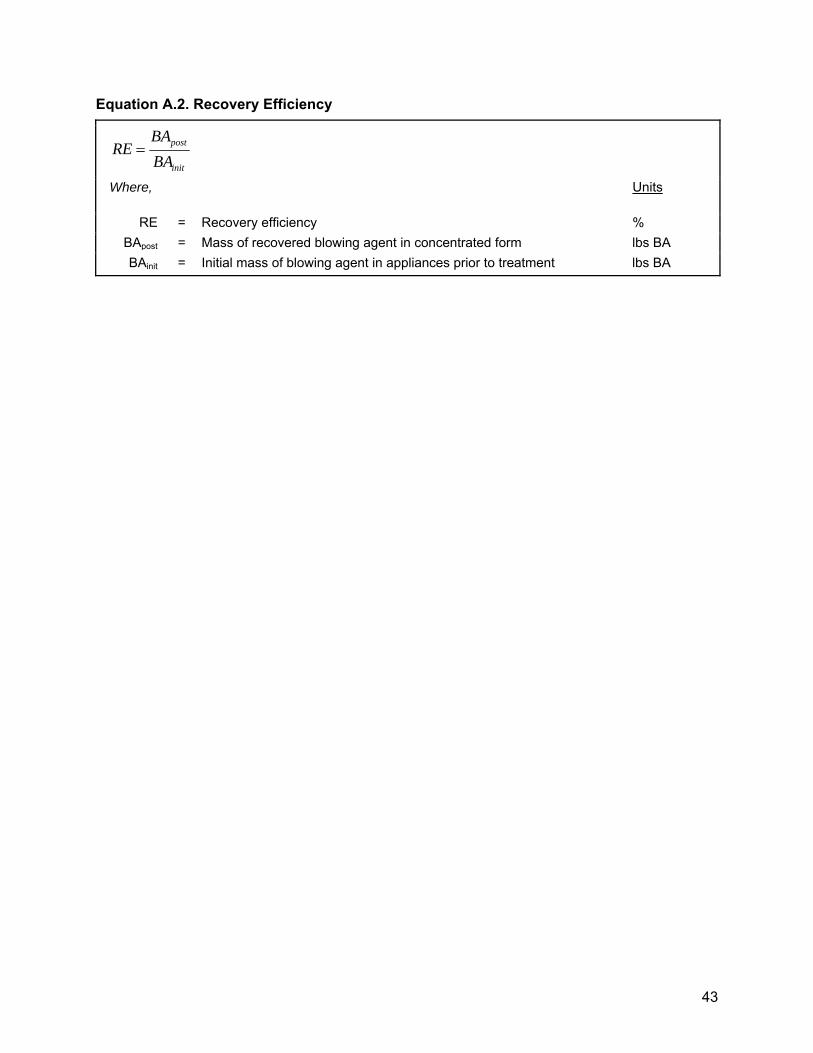
43
Equation A.2. Recovery Efficiency
init
post
BA
BARE
Where,
Units
RE = Recovery efficiency % BApost = Mass of recovered blowing agent in concentrated form lbs BA BAinit = Initial mass of blowing agent in appliances prior to treatment lbs BA
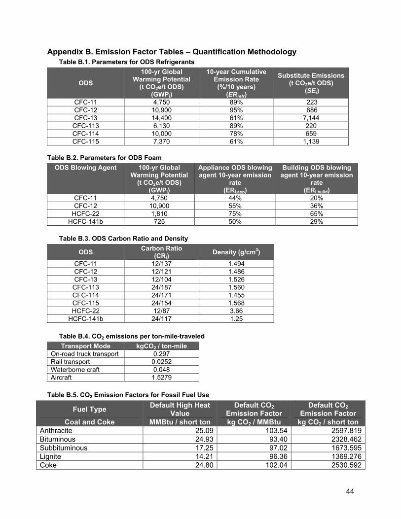
44
Appendix B. Emission Factor Tables – Quantification Methodology Table B.1. Parameters for ODS Refrigerants
ODS 100-yr Global
Warming Potential (t CO2e/t ODS)
(GWPi)
10-year Cumulative Emission Rate (%/10 years)
(ERrefr)
Substitute Emissions (t CO2e/t ODS)
(SEi)
CFC-11 4,750 89% 223 CFC-12 10,900 95% 686 CFC-13 14,400 61% 7,144
CFC-113 6,130 89% 220 CFC-114 10,000 78% 659 CFC-115 7,370 61% 1,139
Table B.2. Parameters for ODS Foam
ODS Blowing Agent 100-yr Global Warming Potential
(t CO2e/t ODS) (GWPi)
Appliance ODS blowing agent 10-year emission
rate (ERi,app)
Building ODS blowing agent 10-year emission
rate (ERi,build)
CFC-11 4,750 44% 20% CFC-12 10,900 55% 36%
HCFC-22 1,810 75% 65% HCFC-141b 725 50% 29%
Table B.3. ODS Carbon Ratio and Density
ODS Carbon Ratio (CRi)
Density (g/cm3)
CFC-11 12/137 1.494 CFC-12 12/121 1.486 CFC-13 12/104 1.526
CFC-113 24/187 1.560 CFC-114 24/171 1.455 CFC-115 24/154 1.568 HCFC-22 12/87 3.66
HCFC-141b 24/117 1.25 Table B.4. CO2 emissions per ton-mile-traveled Transport Mode kgCO2 / ton-mile
On-road truck transport 0.297 Rail transport 0.0252 Waterborne craft 0.048 Aircraft 1.5279
Table B.5. CO2 Emission Factors for Fossil Fuel Use
Fuel Type Default High Heat Value
Default CO2 Emission Factor
Default CO2 Emission Factor
Coal and Coke MMBtu / short ton kg CO2 / MMBtu kg CO2 / short ton Anthracite 25.09 103.54 2597.819Bituminous 24.93 93.40 2328.462Subbituminous 17.25 97.02 1673.595Lignite 14.21 96.36 1369.276Coke 24.80 102.04 2530.592
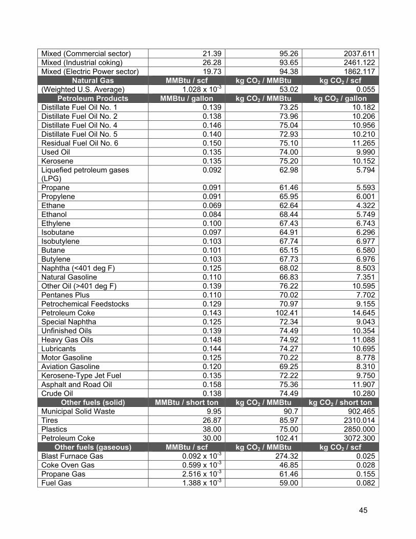
45
Mixed (Commercial sector) 21.39 95.26 2037.611Mixed (Industrial coking) 26.28 93.65 2461.122Mixed (Electric Power sector) 19.73 94.38 1862.117
Natural Gas MMBtu / scf kg CO2 / MMBtu kg CO2 / scf (Weighted U.S. Average) 1.028 x 10⁻³ 53.02 0.055
Petroleum Products MMBtu / gallon kg CO2 / MMBtu kg CO2 / gallon Distillate Fuel Oil No. 1 0.139 73.25 10.182Distillate Fuel Oil No. 2 0.138 73.96 10.206Distillate Fuel Oil No. 4 0.146 75.04 10.956Distillate Fuel Oil No. 5 0.140 72.93 10.210Residual Fuel Oil No. 6 0.150 75.10 11.265Used Oil 0.135 74.00 9.990Kerosene 0.135 75.20 10.152Liquefied petroleum gases (LPG)
0.092 62.98 5.794
Propane 0.091 61.46 5.593Propylene 0.091 65.95 6.001Ethane 0.069 62.64 4.322Ethanol 0.084 68.44 5.749Ethylene 0.100 67.43 6.743Isobutane 0.097 64.91 6.296Isobutylene 0.103 67.74 6.977Butane 0.101 65.15 6.580Butylene 0.103 67.73 6.976Naphtha (<401 deg F) 0.125 68.02 8.503Natural Gasoline 0.110 66.83 7.351Other Oil (>401 deg F) 0.139 76.22 10.595Pentanes Plus 0.110 70.02 7.702Petrochemical Feedstocks 0.129 70.97 9.155Petroleum Coke 0.143 102.41 14.645Special Naphtha 0.125 72.34 9.043Unfinished Oils 0.139 74.49 10.354Heavy Gas Oils 0.148 74.92 11.088Lubricants 0.144 74.27 10.695Motor Gasoline 0.125 70.22 8.778Aviation Gasoline 0.120 69.25 8.310Kerosene-Type Jet Fuel 0.135 72.22 9.750Asphalt and Road Oil 0.158 75.36 11.907Crude Oil 0.138 74.49 10.280
Other fuels (solid) MMBtu / short ton kg CO2 / MMBtu kg CO2 / short ton Municipal Solid Waste 9.95 90.7 902.465Tires 26.87 85.97 2310.014Plastics 38.00 75.00 2850.000Petroleum Coke 30.00 102.41 3072.300
Other fuels (gaseous) MMBtu / scf kg CO2 / MMBtu kg CO2 / scf Blast Furnace Gas 0.092 x 10⁻³ 274.32 0.025Coke Oven Gas 0.599 x 10⁻³ 46.85 0.028Propane Gas 2.516 x 10⁻³ 61.46 0.155Fuel Gas 1.388 x 10⁻³ 59.00 0.082

46
Biomass Fuels – (solid) MMBtu / short ton kg CO2 / MMBtu kg CO2 / short ton Wood and Wood Residuals 15.38 93.80 1442.644Agricultural Byproducts 8.25 118.17 974.903Peat 8.00 111.84 894.720Solid Byproducts 25.83 105.51 2725.323Biomass Fuels – (gaseous) MMBtu / scf kg CO2 / MMBtu kg CO2 / scf
Biogas (Captured methane) 0.841 x 10⁻³ 52.07 0.044Biomass Fuels – (liquid) MMBtu / gallon kg CO2 / MMBtu kg CO2 / gallon
Ethanol 0.084 68.44 5.749Biodiesel 0.128 73.84 9.452Rendered Animal Fat 0.125 71.06 8.883Vegetable Oil 0.120 81.55 9.786
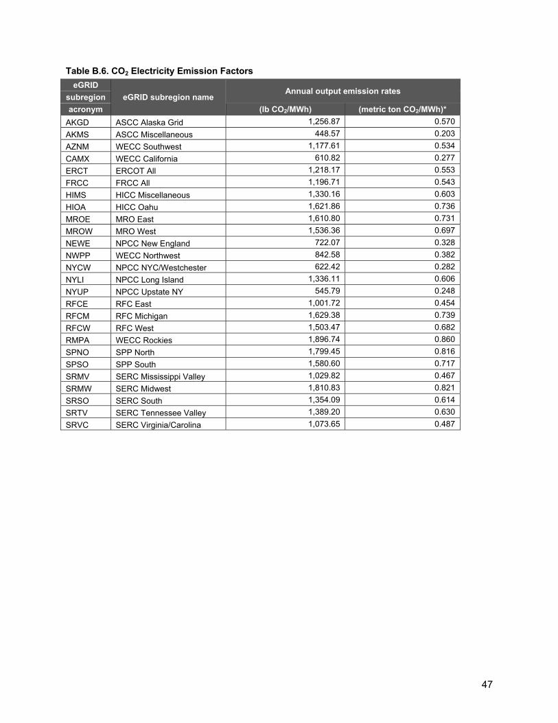
47
Table B.6. CO2 Electricity Emission Factors eGRID
eGRID subregion name Annual output emission rates
subregion acronym (lb CO2/MWh) (metric ton CO2/MWh)*
AKGD ASCC Alaska Grid 1,256.87 0.570 AKMS ASCC Miscellaneous 448.57 0.203 AZNM WECC Southwest 1,177.61 0.534 CAMX WECC California 610.82 0.277 ERCT ERCOT All 1,218.17 0.553 FRCC FRCC All 1,196.71 0.543 HIMS HICC Miscellaneous 1,330.16 0.603 HIOA HICC Oahu 1,621.86 0.736 MROE MRO East 1,610.80 0.731 MROW MRO West 1,536.36 0.697 NEWE NPCC New England 722.07 0.328 NWPP WECC Northwest 842.58 0.382 NYCW NPCC NYC/Westchester 622.42 0.282 NYLI NPCC Long Island 1,336.11 0.606 NYUP NPCC Upstate NY 545.79 0.248 RFCE RFC East 1,001.72 0.454 RFCM RFC Michigan 1,629.38 0.739 RFCW RFC West 1,503.47 0.682 RMPA WECC Rockies 1,896.74 0.860 SPNO SPP North 1,799.45 0.816 SPSO SPP South 1,580.60 0.717 SRMV SERC Mississippi Valley 1,029.82 0.467 SRMW SERC Midwest 1,810.83 0.821 SRSO SERC South 1,354.09 0.614 SRTV SERC Tennessee Valley 1,389.20 0.630 SRVC SERC Virginia/Carolina 1,073.65 0.487

48
Figure B.1. Map of eGRID2010 Subregions

49
Appendix C. ODS Mass and Composition from Building Foam Projects – Quantification Methodology
ODS blowing agent from building insulation foam must be destroyed intact following the
procedures described in this appendix.
(a) The foam’s mass shall be determined on scales at the destruction facility. The
scales must be calibrated at least quarterly with a demonstrated accuracy of +/-
5%.
(b) To determine the composition and mass ratio of the ODS foam blowing agent
present in the foam at least two samples per building surface (e.g., wall, roof)
must be taken. The samples must conform to all of the following requirements:
(1) Each must sample must be at least 2 inches in length, 2 inches in width,
and 2 inches thick;
(2) For storage and transport, each sample must be placed and sealed in a
separate air-tight and water-tight container that is at least 2 millimeters
thick;
(3) The analysis of ODS foam blowing agent content and mass ratio shall be
performed at an independent laboratory unaffiliated with the Offset Project
Operator or Authorized Project Designee. The analysis shall be done
using one of the two following methods: (1) ASTM Method D 7132-05
Standard Test Method for Determination of Retained Blowing Agent in
Extruded Polystyrene Foam or (2) the heating method to extract ODS
blowing agent from the foam samples described in Scheutz et al. (2007).
The Scheutz method must include all of the following steps:
(A) Each sample shall be prepared to a thickness no greater than 1 cm,
placed in a 1123 mL glass bottle, weighed using a calibrated scale,
and sealed with Teflon-coated septa and aluminum caps;
(B) To release the ODS blowing agent from the foam, the samples
must be incubated in an oven for 48 hours at 140 degrees C;
(C) When cooled to room temperature, gas samples must be redrawn
from the headspace and analyzed by gas chromatography;

50
(D) The lids must be removed after analysis, and the headspace must
be flushed with atmospheric air for approximately 5 minutes using a
compressor. Afterwards, septa and caps must be replaced and the
bottles subjected to a second 48-hr heating step to drive out the
remaining ODS blowing agent from the sampled foam; and
(E) When cooled down to room temperature after the second heating
step, gas samples must be redrawn from the headspace and
analyzed by gas chromatography;.
(4) The mass of ODS foam blowing agent recovered shall then be divided by
the total mass of the initial foam samples prior to analysis to determine the
mass fraction of each ODS foam blowing agent present; and
(5) The results from all samples from a single building shall be averaged to
determine the mass fraction of blowing agent in foam (BA%) used in
equation 5.4.

51
Appendix D. ODS Mass and Composition from Refrigerant and Appliance Foam Projects – Quantification Methodology
Prior to destruction, the precise mass and composition of both ODS refrigerant and
concentrated ODS foam blowing agent must be determined. The following analysis
must be conducted:
(a) Mass must be determined by individually measuring the weight of each container
of ODS first when it is full prior to destruction and then after destruction is
complete. The mass of ODS and any contaminants is equal to the difference
between the full and empty weight, as measured. To be eligible to receive ARB
offset credits or registry offset credits, all of the following requirements must be
met when weighing the containers of ODS:
(1) A single scale conforming with the requirements in subchapter 6.3 of this
protocol must be used for generating both the full and empty weight tickets
at the destruction facility;
(2) The full weight must be measured no more than 48 hours prior to
commencement of destruction per the CEMS data, if available, or the
Certificate of Destruction;
(3) The empty weight must be measured no more than 48 hours after the
conclusion of destruction per the CEMS data, if available, or, the
Certificate of Destruction; and
(4) Each single compartment, cylinder, drum, or any other eligible ODS
container that has been identified and destined for destruction must be
weighed separately, sampled separately, and treated as a separate
destruction event.
(5) Recovery, collection, and aggregation activities may occur until the
container has been identified and destined for destruction. After the ODS
container has been identified and destined for destruction, ODS must not
be added or removed, except for the purpose of sampling and analysis.
(b) The following procedures must be applied for the full and empty weights required
within 48 hours of both the commencement and conclusion of destruction,
pursuant to subsections (a)(2) and (a)(3) in appendix D of this protocol:
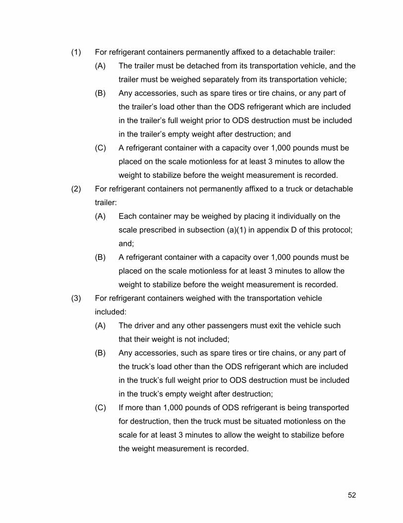
52
(1) For refrigerant containers permanently affixed to a detachable trailer:
(A) The trailer must be detached from its transportation vehicle, and the
trailer must be weighed separately from its transportation vehicle;
(B) Any accessories, such as spare tires or tire chains, or any part of
the trailer’s load other than the ODS refrigerant which are included
in the trailer’s full weight prior to ODS destruction must be included
in the trailer’s empty weight after destruction; and
(C) A refrigerant container with a capacity over 1,000 pounds must be
placed on the scale motionless for at least 3 minutes to allow the
weight to stabilize before the weight measurement is recorded.
(2) For refrigerant containers not permanently affixed to a truck or detachable
trailer:
(A) Each container may be weighed by placing it individually on the
scale prescribed in subsection (a)(1) in appendix D of this protocol;
and;
(B) A refrigerant container with a capacity over 1,000 pounds must be
placed on the scale motionless for at least 3 minutes to allow the
weight to stabilize before the weight measurement is recorded.
(3) For refrigerant containers weighed with the transportation vehicle
included:
(A) The driver and any other passengers must exit the vehicle such
that their weight is not included;
(B) Any accessories, such as spare tires or tire chains, or any part of
the truck’s load other than the ODS refrigerant which are included
in the truck’s full weight prior to ODS destruction must be included
in the truck’s empty weight after destruction;
(C) If more than 1,000 pounds of ODS refrigerant is being transported
for destruction, then the truck must be situated motionless on the
scale for at least 3 minutes to allow the weight to stabilize before
the weight measurement is recorded.

53
(D) The transportation vehicle’s weight classification and load rating
must be recorded;
(E) The transportation vehicle’s fuel capacity must be recorded. Its fuel
level at the time of each scale recording must also be recorded.
Fuel level must be recorded in an increment of one eighth of the
fuel tank capacity. If the fuel level is in between two increments, the
fuel level prior to ODS destruction must be rounded down and the
fuel level after ODS destruction must be rounded up;
(F) If the transportation vehicle’s fuel level is lower after destruction
than the fuel level before destruction, the difference in fuel weight
must be subtracted, as applicable from Qrefr,i in equation 5.3, Qref,i,
in equation 5.6, BAapp,i in equation both equation 5.4 and equation
5.7, and QTotalODS,i in equation 5.8. The following fuel densities shall
be used to adjust for weight:
1. 7.0851 lb/gal for diesel; or
2. 6.0023 lb/gal for gasoline; and
(G) If different transportation vehicles are used to transport containers
to a destruction facility and to pick up the empty containers after
destruction, each transport vehicle shall be weighed both upon its
arrival and departure from the destruction facility. If the vehicle
transporting the full ODS containers to the destruction facility
weighs more than the vehicle carrying the empty ODS containers
from the facility, the weight discrepancy must be subtracted, as
applicable from Qrefr,i in equation 5.3, Qref,i, in equation 5.6, BAapp,i in
both equation 5.4 and equation 5.7, and QTotalODS,i in equation 5.8.
(c) Composition and concentration of ODS must be established for each individual
container by taking a sample from each container of ODS and having it analyzed
for composition and concentration at an AHRI-certified laboratory using the AHRI
700-2006 standard. The laboratory performing the composition analysis must
not be affiliated with the Offset Project Operator or Authorized Project Designee.
All of the following requirements must be met for each sample:

54
(1) The sample must be taken while ODS is in the possession of the company
that will destroy the ODS;
(2) Samples must be taken by a technician unaffiliated with the Offset Project
Operator or Authorized Project Designee; if the destruction facility is either
the Offset Project Operator or Authorized Project Designee, an outside
technician must perform this task;
(3) Samples must be taken with a clean, fully evacuated sample bottle that
meets applicable DOT requirements with a minimum capacity of one
pound;
(4) Each sample must be taken in liquid state;
(5) A minimum sample size of one pound must be drawn for each sample;
(6) Each sample must be individually labeled and tracked according to the
container from which it was taken, and all of the following information
recorded:
(A) Time and date of sample;
(B) Name of Offset Project Operator and Authorized Project Designee;
(C) Name of technician taking sample;
(D) Employer of technician taking sample;
(E) Volume of container from which sample was extracted; and
(F) Ambient air temperature at time of sampling; and
(7) Chain of custody for each sample from the point of sampling to the AHRI
lab must be documented by paper bills of lading or electronic, third-party
tracking that includes proof of delivery.
(d) All project samples shall be analyzed using AHRI 700-2006 to confirm the mass
percentage and identity of each component of the sample. The analysis shall
provide:
(1) Identification of the refrigerant;
(2) Purity (%) of the ODS mixture by weight using gas chromatography;
(3) Moisture level in parts per million. The moisture content of each sample
must be less than 75% of the saturation point for the ODS based on the
temperature recorded at the time the sample was taken;

55
(A) For non-mixed ODS, the saturation point is the saturation point of
the major ODS species;
(B) For mixed ODS, the saturation point is the lowest saturation value
of any species that makes up at least 10% of the composition;
(4) Analysis of high boiling residue, which must be less than 10% by mass;
and
(5) Analysis of other ODS in the case of mixtures of ODS, and their
percentage by mass.
(e) If any of the requirements in sections (a) through (c) of this appendix are not met,
no GHG reductions may be verified for ODS destruction associated with that
container.
(f) If a container holds non-mixed ODS, no further information or sampling is
required to determine the mass and composition of the ODS. For non-mixed
ODS, the analysis conducted for the sample taken at the destruction facility must
be used for quantifying GHG emissions.
(g) If the container holds mixed ODS, the Offset Project Operator or Authorized
Project Designee must meet all of the following additional requirements:
(1) The required sampling may be conducted at the final destruction facility or
prior to delivery to the destruction facility;
(2) Circulation and sampling activities must be conducted by a contracted
third-party and by individuals who have been properly trained for the
functions they perform;
(3) The offset project documentation must specify the procedures by which
mixed ODS are analyzed;
(4) Prior to sampling, the ODS mixture must be circulated in a container that
meets all of the following criteria:
(A) The container has no solid interior obstructions;
(B) The container was fully evacuated prior to filling;
(C) The container must have sampling ports to sample liquid and gas
phase ODS;

56
(D) The sampling ports must be located in the middle third of the
container (i.e., not at one end or the other); and
(E) The container and associated equipment can circulate the mixture
via a closed loop system from the bottom to top;
(5) If the original mixed ODS container does not meet these requirements, the
mixed ODS must be transferred into a temporary holding tank or container
that meets all of the above criteria. The weight of the contents placed into
the temporary container shall be calculated and recorded. During transfer
of ODS into and out of the temporary container, ODS shall be recovered
to the vacuum levels required by the U.S. EPA for that ODS (see 40 CFR
82.156);
(6) Once the mixed ODS is in a container or temporary storage unit that
meets the criteria above, circulation of mixed ODS must be conducted as
follows:
(A) Liquid mixture shall be circulated from the liquid port to the vapor
port;
(B) A volume of the mixture equal to two times the volume in the
container shall be circulated;
(C) Calculations converting between mass and volume shall use the
densities provided in table B.3; if converting between mass and
volume, the mixed ODS must be in a liquid state;
(D) Circulation must occur at a rate of at least 30 gallons/minute; and
(E) Start and end times shall be recorded;
(7) Within 30 minutes of the completion of circulation, a minimum of two
samples shall be taken from the bottom liquid port, and both samples must
be analyzed at an AHRI approved laboratory; and
(8) The Offset Project Operator or Authorized Project Designee must
calculate the project GHG emission reductions using both sample results,
and choose the sample resulting in the lower project emission reductions.

601 W. 5th Street, Suite 650 Los Angeles, California 90071www.climateactionreserve.orgT: (213) 891 1444
U.S. Ozone Depleting Substances Project Protocol V2.0Protocol Summary
Project DefinitionAny set of activities undertaken by a single project developer resulting in the destruction of eligible ozone depleting substances (ODS) at a single qualifying destruction facility over a 12-month period.
All ODS must be documented on one or more Certificates of Destruction and destroyed at either: z A hazardous waste combustor approved by the Resource Conservation and Recovery Act (RCRA) or z A facility that meets the guidelines in the Technology and Economic Assessment Panel (TEAP) Report of the Task Force on Destruction Technologies (2002)
Project Eligibility RequirementsLocation: ODS must be sourced from the U.S. or its territories and destroyed within the U.S. or its territories.
Start Date: Project must be submitted within six months of the project start date. Performance Standard: Project must collect, track and destroy ODS refrigerants (CFC-11, CFC-12, CFC-13, CFC-113, CFC-114, CFC-115) or ODS foam blowing agents (CFC-11, CFC-12, HCFC-22, HCFC-141b) sourced from within the U.S. or its territories that have been phased out of production for that application.
Legal Requirement Test: The project exceeds any reductions that would have occurred as a result of compliance with international, federal, state or local regulations. The Montreal Protocol and U.S. law limit the production and intentional release of ODS but do not require destruction. The project is subject to a review of the legal requirement test for each reporting period and the project developer must sign the Attestation of Voluntary Implementation.
Regulatory Compliance: Project must be in compliance with all federal, state and local regulations relevant to the project activities, including the operation of the ODS destruction facility and, if applicable, mixing facility. Project developer must sign the Attestation of Regulatory Compliance for each reporting period.
Crediting Period: ODS projects are defined as a discrete series of destruction events, but the avoided emissions would have occurred over a longer time horizon. Climate Reserve Tonnes (CRTs) will be issued for the quantity of ODS emissions that would have occurred over a 10-year crediting period. All CRTs will be issued upon successful completion of verification.
Reporting and Verification Schedule: Project may report and undergo verification annually or sub-annually.
Other Eligibility Requirements: z Project must track all ODS to point of origin z Clear ownership of the greenhouse gas (GHG) emissions reductions must be established z Project must not double register emissions reductions with any other registry system z Project must conduct proper accounting, monitoring, operation and tracking
Project Is Ineligible If: z ODS is imported to the U.S. (see Article 5 Ozone Depleting Substances Project Protocol V2.0) z ODS is derived from solvents, fire suppressant halons, medical applications and from sources deemed hazardous waste
z Project involves destruction of intact appliance foam containing ODS blowing agents
Important Note: This is a summary of the protocol. Please read the full protocol for a complete description of project requirements.

601 W. 5th Street, Suite 650Los Angeles, California 90071www.climateactionreserve.orgT: (213) 891 1444
Article 5 Ozone Depleting Substances Project Protocol V2.0Protocol Summary
Project DefinitionAny set of activities undertaken by a single project developer resulting in the destruction of eligible ozone depleting substances (ODS) at a single qualifying destruction facility over a 12-month period.
All ODS must be documented on one or more Certificates of Destruction and destroyed at either: z A hazardous waste combustor approved by the Resource Conservation and Recovery Act (RCRA) or z A facility that meets the guidelines in the Technology and Economic Assessment Panel (TEAP) Report of the Task Force on Destruction Technologies (2002)
Project Eligibility RequirementsLocation: ODS must be sourced from an Article 5 country and destroyed within the U.S. or its territories.
Start Date: Project must be submitted within six months of the project start date.
Performance Standard: Project must collect, track and destroy ODS refrigerants (CFC-11, CFC-12, CFC-113, CFC-114, CFC-115) sourced from within Article 5 countries and that have been phased out of production.
Legal Requirement Test: The project exceeds any reductions that would have occurred as a result of compliance with international treaty obligations or local regulations. The Montreal Protocol limits the production of ODS but does not require destruction. The project is subject to a review of the legal requirement test for each reporting period and the project developer must sign the Attestation of Voluntary Implementation.
Regulatory Compliance: Project must be in compliance with all national, state and local regulations relevant to the project activity, including the import of ODS to the U.S. for destruction and the operation of the ODS destruction facility and, if applicable, mixing facility. Project developer must sign the Attestation of Regulatory Compliance for each reporting period.
Crediting Period: ODS projects are defined as a discrete series of destruction events, but the avoided emissions would have occurred over a longer time horizon. Climate Reserve Tonnes (CRTs) will be issued for the quantity of ODS emissions that would have occurred over a 10-year crediting period. All CRTs will be issued upon successful completion of verification.
Reporting and Verification Schedule: Project may report and undergo verification annually or sub-annually.
Other Eligibility Requirements: z Project must track all ODS to point of origin z All ODS must be exported from the country of origin after the production phase-out date in that country z Clear ownership of the greenhouse gas (GHG) emissions reductions must be established z Project must not double register emissions reductions with any other registry system z Project must conduct proper accounting, monitoring, operation and tracking
Project Is Ineligible If: z ODS is sourced from non-Article 5 countries z ODS is sourced from the U.S. (see U.S. Ozone Depleting Substances Project Protocol V2.0) z ODS is derived from solvents, fire suppressant halons, medical applications and foams z Project involves destruction that occurs outside of the U.S. or its territories
Important Note: This is a summary of the protocol. Please read the full protocol for a complete description of project requirements.

Please ensure that you are using the latest version of this document
Article 5 Ozone Depleting Substances Project Protocol Version 2.0
ERRATA AND CLARIFICATIONS The Climate Action Reserve (Reserve) published its Article 5 Ozone Depleting Substances Project Protocol Version 2.0 (A5 ODS V2.0) in June 2012. While the Reserve intends for the A5 ODS V2.0 to be a complete, transparent document, it recognizes that correction of errors and clarifications will be necessary as the protocol is implemented and issues are identified. This document is an official record of all errata and clarifications applicable to the A5 ODS V2.0.1 Per the Reserve’s Program Manual, both errata and clarifications are considered effective on the date they are first posted on the Reserve website. The effective date of each erratum or clarification is clearly designated below. All listed and registered A5 ODS projects must incorporate and adhere to these errata and clarifications when they undergo verification. The Reserve will incorporate both errata and clarifications into future versions of the Article 5 ODS Project Protocol. All project developers and verification bodies must refer to this document to ensure that the most current guidance is adhered to in project design and verification. Verification bodies shall refer to this document immediately prior to uploading any Verification Statement to assure all issues are properly addressed and incorporated into verification activities. If you have any questions about the updates or clarifications in this document, please contact Policy at [email protected] or (213) 891-1444 x3.
1 See Section 4.3.4 of the Climate Action Reserve Program Manual for an explanation of the Reserve’s policies on protocol errata and clarifications. “Errata” are issued to correct typographical errors. “Clarifications” are issued to ensure consistent interpretation and application of the protocol. For document management and program implementation purposes, both errata and clarifications are contained in this single document.
Article 5 Ozone Depleting Substances Project Protocol Version 2.0 June 5, 2017 Errata and Clarifications
Please ensure that you are using the latest version of this document 1
Errata and Clarifications (arranged by protocol section)
Section 5
1. Correcting a Citation for Refrigerant Baseline Scenarios (ERRATUM – June 5, 2017) .... 2 2. Accounting for Non-ODS Material (CLARIFICATION – January 29, 2013) ....................... 2 3. Performance Requirements for Destruction Facilities (ERRATUM – July 16, 2015) ......... 3
Section 6
4. Determining the Mass of ODS Destroyed (CLARIFICATION – April 11, 2013) ................. 3

Article 5 Ozone Depleting Substances Project Protocol Version 2.0 June 5, 2017 Errata and Clarifications
Please ensure that you are using the latest version of this document 2
Section 5
1. Correcting a Citation for Refrigerant Baseline Scenarios (ERRATUM – June 5, 2017) Section: 5.1 (Quantifying Baseline Emissions), Table 5.1. Refrigerant Baseline Scenarios Context: Footnote 17 on page 16 reads “United Nations Environment Programme, Technology and Economic Assessment Panel. (2005). Report of the Task Force on Foam End-of-Life Issues.” While the value in Table 5.1 that is attributed to this reference (25%) is correct, the reference itself cites the incorrect UNEP TEAP Report. Correction: Footnote 17, Table 5.1, page 16 shall be replaced with the following citation:
United Nations Environment Programme, Technology and Economic Assessment Panel. (2007). Report of the Task Force on HCFC Issues (with Particular Focus on the Impact of the Clean Development Mechanism) and Emissions Reduction Benefits Arising from Earlier HCFC Phase-out and Other Practical Measures.
2. Accounting for Non-ODS Material (CLARIFICATION – January 29, 2013) Section: 5.1 (Quantifying Baseline Emissions) Context: The protocol states that projects shall only include the weight of pure ODS when calculating emission reductions. There are additional specific adjustments that were not mentioned in the protocol and it may not be clear how these adjustments should be made. Specifically, project developers shall exclude the weight of high boiling residue (HBR) in their calculation of emission reductions. Clarification: The definition of the term “Qrefr,i” in Equation 5.3 on page 17 shall read “Total quantity of pure refrigerant ODS i sent for destruction by the project.” The total weight of material destroyed by the project shall be adjusted to exclude the weight of ineligible material, including high boiling residue, as determined by the laboratory analysis required in Section 6.6 (in the case of multiple laboratory analyses, the highest reported value for HBR shall be used). In any case where the composition of the single ODS species is less than 100%, the value of this term must be adjusted to reflect the weight of pure ODS for each eligible chemical. For example, if a project destroys 1,000 lbs. of material that contains 5% high boiling residue and 95% eligible ODS i, the value of Qrefr,i would be 902.5 lbs. While water is also considered ineligible material, the moisture content requirement in Section 6.6 of the protocol (i.e. that the moisture content must be less than 75% of the saturation point for the ODS) already ensures that the weight of any moisture present will not have a material impact on the quantification of emission reductions. Thus the weight does not need to be adjusted to reflect the weight of moisture present in the sample.

Article 5 Ozone Depleting Substances Project Protocol Version 2.0 June 5, 2017 Errata and Clarifications
Please ensure that you are using the latest version of this document 3
3. Performance Requirements for Destruction Facilities (ERRATUM – July 16, 2015) Section: 5.2.3 (Calculating Site-Specific Project Emissions from ODS Destruction) Context: The protocol states that destruction facilities “demonstrate their ability to achieve destruction efficiencies upwards of 99.99 percent for substances with thermal stability ratings higher than the ODS included herein” (emphasis added). The reference cited for this statement explains a ranking system for the incinerability of ODS species based on their thermal stability. In this system, ODS species that are more thermally stable are more difficult to destroy. This results in a lower ranking. Thus, the lowest ranking (1) indicates the chemical that is most difficult to destroy, while the highest ranking (320) indicates the chemical that is easiest to destroy. The above-quoted statement in the A5 ODS Project Protocol includes an error that communicates the opposite of the intended meaning of the statement. Correction: The second sentence in the first paragraph of this section shall read: “These facilities demonstrate their ability to achieve destruction efficiencies upwards of 99.99 percent for substances with thermal stability rankings lower than the ODS included herein.”
Section 6
4. Determining the Mass of ODS Destroyed (CLARIFICATION – April 11, 2013) Section: 6.4 (ODS Composition and Quantity Analysis Requirements) Context: The protocol requires that the mass of ODS destroyed by the project be determined using (1) the difference between the measured weight of each container when it is full prior to destruction and the measured weight after it has been emptied and (2) the composition and concentration of material destroyed as determined by laboratory analyses of samples from each container. Clarification: The mass of ODS and any contaminants destroyed shall be considered equal to the difference between the full and empty weights of the containers, as measured by the scale at the destruction facility and recorded by the destruction facility on the weight tickets and the Certificate of Destruction. No adjustments shall be made by the project developer to the weights as measured and recorded by the destruction facility in calculating the mass of ODS and contaminants.
Verifiers shall confirm that the weights recorded on the weight tickets and the Certificate of Destruction by the destruction facility are used without adjustment to calculate emission reductions. The mass of eligible ODS shall then be determined using these weights and the results of the laboratory analyses.

Ozone Depleting SubstancesArticle 5 | Version 2.0 | June 27, 2012
Project Protocol

Climate Action Reserve 601 West 5th Street, Suite 650 Los Angeles, CA 90071 www.climateactionreserve.org Released June 27, 2012 © 2012 Climate Action Reserve. All rights reserved. This material may not be reproduced, displayed, modified or distributed without the express written permission of the Climate Action Reserve.
Article 5 ODS Project Protocol Version 2.0, June 2012
Acknowledgements Staff Tim Kidman Climate Action Reserve Jette Findsen SAIC Rachel Tornek Climate Action Reserve Derik Broekhoff Climate Action Reserve Max DuBuisson Climate Action Reserve Workgroup
Paul Ashford Caleb Management Services Ltd. Jack Cameron Appliance Recycling Centers of America Jeff Cohen EOS Climate Jesse Combs Coolgas Inc. Richard Corey California Air Resources Board John Demeter Wesco - Halon Management and Banking Ted Gartland Verisae Inc Debra Goodge DuPont Refrigerants Tim Juliani Pew Center on Global Climate Change Timothy Kearney RemTec International Mark Lowry Refrigeration Service Engineers Society Stephen Mandracchia Hudson Technologies Company Bella Maranion U.S. Environmental Protection Agency Derek Markolf Ryerson, Masters & Associates John McNally Clean Harbors Environmental Services, Inc. Scott Miller Sims Metal Management Adam Penque Greenhouse Gas Services John Shideler NSF-ISR Derek Six Environmental Credit Corp Patricia Stanton Conservation Services Group Viraj Vithoontien World Bank Mark Wagner ICF International Kurt Werner 3M
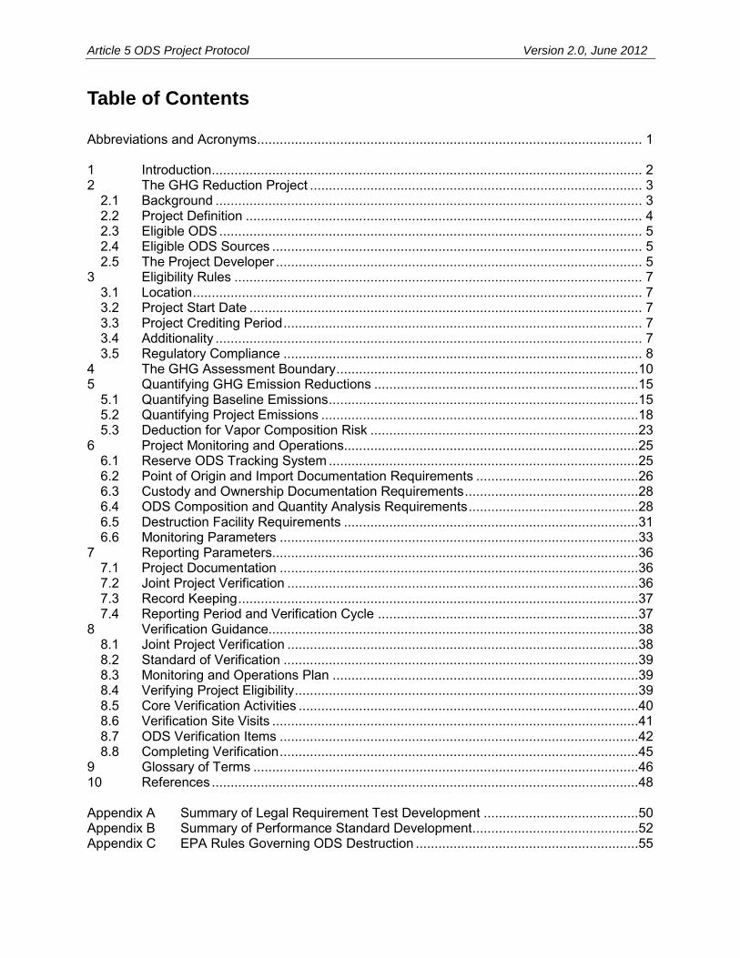
Article 5 ODS Project Protocol Version 2.0, June 2012
Table of Contents Abbreviations and Acronyms ...................................................................................................... 1 1 Introduction .................................................................................................................. 2 2 The GHG Reduction Project ........................................................................................ 3
2.1 Background ................................................................................................................. 3 2.2 Project Definition ......................................................................................................... 4 2.3 Eligible ODS ................................................................................................................ 5 2.4 Eligible ODS Sources .................................................................................................. 5 2.5 The Project Developer ................................................................................................. 5
3 Eligibility Rules ............................................................................................................ 7 3.1 Location ....................................................................................................................... 7 3.2 Project Start Date ........................................................................................................ 7 3.3 Project Crediting Period ............................................................................................... 7 3.4 Additionality ................................................................................................................. 7 3.5 Regulatory Compliance ............................................................................................... 8
4 The GHG Assessment Boundary ................................................................................10 5 Quantifying GHG Emission Reductions ......................................................................15
5.1 Quantifying Baseline Emissions ..................................................................................15 5.2 Quantifying Project Emissions ....................................................................................18 5.3 Deduction for Vapor Composition Risk .......................................................................23
6 Project Monitoring and Operations..............................................................................25 6.1 Reserve ODS Tracking System ..................................................................................25 6.2 Point of Origin and Import Documentation Requirements ...........................................26 6.3 Custody and Ownership Documentation Requirements ..............................................28 6.4 ODS Composition and Quantity Analysis Requirements .............................................28 6.5 Destruction Facility Requirements ..............................................................................31 6.6 Monitoring Parameters ...............................................................................................33
7 Reporting Parameters.................................................................................................36 7.1 Project Documentation ...............................................................................................36 7.2 Joint Project Verification .............................................................................................36 7.3 Record Keeping ..........................................................................................................37 7.4 Reporting Period and Verification Cycle .....................................................................37
8 Verification Guidance..................................................................................................38 8.1 Joint Project Verification .............................................................................................38 8.2 Standard of Verification ..............................................................................................39 8.3 Monitoring and Operations Plan .................................................................................39 8.4 Verifying Project Eligibility ...........................................................................................39 8.5 Core Verification Activities ..........................................................................................40 8.6 Verification Site Visits .................................................................................................41 8.7 ODS Verification Items ...............................................................................................42 8.8 Completing Verification ...............................................................................................45
9 Glossary of Terms ......................................................................................................46 10 References .................................................................................................................48 Appendix A Summary of Legal Requirement Test Development .........................................50 Appendix B Summary of Performance Standard Development ............................................52 Appendix C EPA Rules Governing ODS Destruction ...........................................................55

Article 5 ODS Project Protocol Version 2.0, June 2012
Appendix D Default Emissions Factors for Calculating ODS Transportation and Destruction Emissions .........................................................................................................61
Appendix E Emission Factor Tables ....................................................................................63 Appendix F ODS Project Diagram Sample ..........................................................................64 List of Tables Table 2.1. Production Phase-Out Schedule of the Montreal Protocol for Article 5 Countries ...... 3 Table 4.1. Illustration of the GHG Assessment Boundary ..........................................................11 Table 5.1. Refrigerant Baseline Scenarios ................................................................................16 Table 5.2. Global Warming Potential of Eligible ODS Refrigerants ............................................17 Table 5.3. Eligible Low Pressure and High Pressure ODS ........................................................23 Table 5.4. Determining the Deduction for Vapor Composition Risk ...........................................24 Table 6.1. Identification of Point of Origin ..................................................................................26 Table 6.2. ODS Project Monitoring Parameters .........................................................................34 Table 8.1. Summary of Eligibility Criteria ...................................................................................39 Table 8.2. Verification Site Visit Requirements ..........................................................................41 Table 8.3. Eligibility Verification Items .......................................................................................42 Table 8.4. Operational Requirement and ODS Eligibility Verification Items ...............................43 Table 8.5. Quantification Verification Items ...............................................................................44 Table 8.6. Risk Assessment Verification Items ..........................................................................45 Table B.1. Reported Destruction of ODS in Article 5 Countries……………………………………52 Table B.2. Destruction of ODS in Article 5 Countries (1990 to 2008) .........................................53 Table B.3. Destruction of ODS in Article 5 Countries (2005 to 2008) .........................................53 Table D.1. Project Emissions (Excluding Substitutes)………………………………………………62 Table E.1. CO2 Emission Factors for Fossil Fuel Use………………………………………………63 List of Figures Figure 4.1. Illustration of the GHG Assessment Boundary ........................................................10 List of Equations Equation 5.1. Total Emission Reductions ..................................................................................15 Equation 5.2. Calculating Site-Specific Emission Rate ..............................................................16 Equation 5.3. Baseline Emissions .............................................................................................17 Equation 5.4. Total Project Emissions .......................................................................................19 Equation 5.5. Calculating Project Emissions from the Use of Non-ODS Refrigerants ................20 Equation 5.6. Project Emissions from Transportation and Destruction Using the Default
Emission Factors .................................................................................................20 Equation 5.7. Project Emissions from the Destruction of ODS ..................................................21 Equation 5.8. Fossil Fuel Emissions from the Destruction of ODS ............................................21 Equation 5.9. Electricity Emissions from the Destruction of ODS ..............................................21 Equation 5.10. Calculating Project Emissions from ODS Not Destroyed ...................................22 Equation 5.11. Calculating Project Emissions of CO2 from the Oxidation of ODS ......................22 Equation 5.12. Calculating Project Emissions from the Transportation of ODS .........................23 Equation 5.13. Determining Liquid Fill Level in Project Container .............................................24
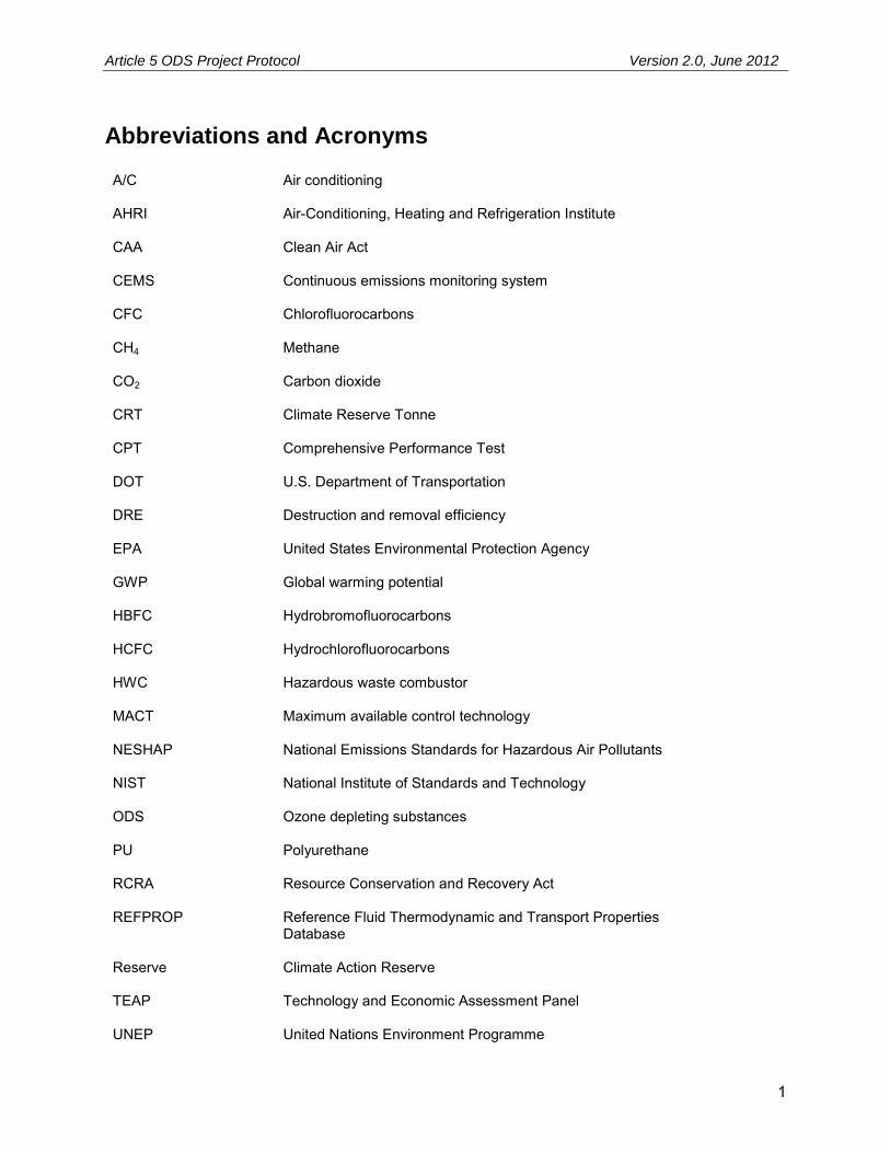
Article 5 ODS Project Protocol Version 2.0, June 2012
1
Abbreviations and Acronyms A/C
Air conditioning
AHRI
Air-Conditioning, Heating and Refrigeration Institute
CAA
Clean Air Act
CEMS
Continuous emissions monitoring system
CFC
Chlorofluorocarbons
CH4
Methane
CO2
Carbon dioxide
CRT
Climate Reserve Tonne
CPT
Comprehensive Performance Test
DOT U.S. Department of Transportation
DRE
Destruction and removal efficiency
EPA
United States Environmental Protection Agency
GWP
Global warming potential
HBFC Hydrobromofluorocarbons
HCFC
Hydrochlorofluorocarbons
HWC
Hazardous waste combustor
MACT
Maximum available control technology
NESHAP
National Emissions Standards for Hazardous Air Pollutants
NIST
National Institute of Standards and Technology
ODS
Ozone depleting substances
PU Polyurethane
RCRA
Resource Conservation and Recovery Act
REFPROP Reference Fluid Thermodynamic and Transport Properties Database
Reserve
Climate Action Reserve
TEAP
Technology and Economic Assessment Panel
UNEP United Nations Environment Programme

Article 5 ODS Project Protocol Version 2.0, June 2012
2
1 Introduction The Climate Action Reserve Article 5 Ozone Depleting Substances Project Protocol provides guidance to account for, report, and verify greenhouse gas (GHG) emission reductions associated with destruction of high global warming potential ozone depleting substances (ODS) in the United States (U.S.) that are sourced from Article 5 countries, and that would have otherwise been released to the atmosphere. This project type includes only ODS used in refrigerant applications. All destroyed ODS must originate in an Article 5 country and be fully documented, chemically analyzed, and destroyed at a qualifying destruction facility within the United States to be eligible for crediting under this protocol. Projects wishing to generate credits from the destruction of ODS originating inside the U.S. must use the Climate Action Reserve’s U.S. Ozone Depleting Substances Project Protocol. As the premier carbon offset registry for the North American carbon market, the Climate Action Reserve works to ensure environmental benefit, integrity and transparency in market-based solutions that reduce greenhouse gas emissions. It establishes high quality standards for carbon offset projects, oversees independent third-party verification bodies, issues carbon credits generated from such projects and tracks the transaction of credits over time in a transparent, publicly-accessible system. By facilitating and encouraging the creation of GHG emission reduction projects, the Climate Action Reserve program promotes immediate environmental and health benefits to local communities, allows project developers access to additional revenues and brings credibility and value to the carbon market. The Climate Action Reserve is a private 501c(3) nonprofit organization based in Los Angeles, California. ODS project developers must use this document to quantify, verify, and report GHG reductions with the Reserve. The protocol provides eligibility rules, methods to calculate reductions, performance-monitoring instructions, and procedures for reporting project information to the Reserve. Additionally, all project reports must submit to annual, independent verification by ISO-accredited and Reserve-approved verification bodies. Guidance for verification bodies to verify reductions is provided in the Reserve Verification Program Manual and Section 8 of this protocol. This protocol is designed to ensure the complete, consistent, transparent, accurate, and conservative quantification and verification of GHG emission reductions associated with an ODS destruction project.1
1 See the WRI/WBCSD GHG Protocol for Project Accounting (Part I, Chapter 4) for a description of GHG reduction project accounting principles. 2 United Nations Environment Programme, Ozone Secretariat. (1987 and subsequent amendments). The Montreal
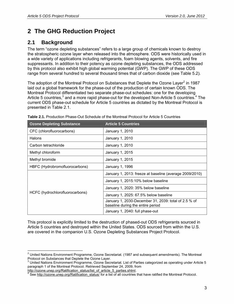
Article 5 ODS Project Protocol Version 2.0, June 2012
3
2 The GHG Reduction Project
2.1 Background The term “ozone depleting substances” refers to a large group of chemicals known to destroy the stratospheric ozone layer when released into the atmosphere. ODS were historically used in a wide variety of applications including refrigerants, foam blowing agents, solvents, and fire suppressants. In addition to their potency as ozone depleting substances, the ODS addressed by this protocol also exhibit high global warming potential (GWP). The GWP of these ODS range from several hundred to several thousand times that of carbon dioxide (see Table 5.2). The adoption of the Montreal Protocol on Substances that Deplete the Ozone Layer2 in 1987 laid out a global framework for the phase-out of the production of certain known ODS. The Montreal Protocol differentiated two separate phase-out schedules: one for the developing Article 5 countries,3 and a more rapid phase-out for the developed Non-Article 5 countries.4 The current ODS phase-out schedule for Article 5 countries as dictated by the Montreal Protocol is presented in Table 2.1. Table 2.1. Production Phase-Out Schedule of the Montreal Protocol for Article 5 Countries
Ozone Depleting Substance Article 5 Countries
CFC (chlorofluorocarbons) January 1, 2010
Halons January 1, 2010
Carbon tetrachloride January 1, 2010
Methyl chloroform January 1, 2015
Methyl bromide January 1, 2015
HBFC (Hydrobromofluorocarbons) January 1, 1996
HCFC (hydrochlorofluorocarbons)
January 1, 2013: freeze at baseline (average 2009/2010)
January 1, 2015:10% below baseline
January 1, 2020: 35% below baseline
January 1, 2025: 67.5% below baseline January 1, 2030-December 31, 2039: total of 2.5 % of baseline during the entire period January 1, 2040: full phase-out
This protocol is explicitly limited to the destruction of phased-out ODS refrigerants sourced in Article 5 countries and destroyed within the United States. ODS sourced from within the U.S. are covered in the companion U.S. Ozone Depleting Substances Project Protocol.
2 United Nations Environment Programme, Ozone Secretariat. (1987 and subsequent amendments). The Montreal Protocol on Substances that Deplete the Ozone Layer. 3 United Nations Environment Programme, Ozone Secretariat. List of Parties categorized as operating under Article 5 paragraph 1 of the Montreal Protocol. Retrieved September 24, 2009, from http://ozone.unep.org/Ratification_status/list_of_article_5_parties.shtml. 4 See http://ozone.unep.org/Ratification_status/ for a list of all countries that have ratified the Montreal Protocol.

Article 5 ODS Project Protocol Version 2.0, June 2012
4
As of January 1, 2010, the Montreal Protocol has stopped all production of CFC ODS in Article 5 countries, with the exception of certain critical use exemptions. However, this framework does not require the destruction of extant stocks of ODS. Rather, virgin stockpiles may be sold for use, and installed banks may be recovered, recycled, reclaimed, and reused indefinitely, often in equipment with very high leak rates. Because the Montreal Protocol does not forbid the use of existing or recycled controlled substances beyond the phase-out dates, even properly managed ODS banks will eventually be released to the atmosphere during equipment servicing, use, and end-of-life. Prior to the production phase-out in Article 5 countries, equipment utilizing CFC refrigerants was preferred in a wide variety of applications. These applications included industrial and commercial refrigeration, cold storage, comfort cooling equipment (i.e. air conditioning), and various consumer applications. While the production of CFC refrigerants has been phased out, use of these ODS is still widespread, and can be found everywhere from vehicle air conditioners to industrial chillers. These substances continue to be released from equipment through operation, servicing, and end-of-life.
2.2 Project Definition For the purposes of this protocol, a project is defined as any set of activities undertaken by a single project developer resulting in the destruction5 of eligible imported ODS at a single qualifying destruction facility within a 12-month period. Destruction may take place under one or more Certificates of Destruction. Each Certificate of Destruction must document the ODS destroyed. The ODS destroyed may come from a single origin (e.g. one supermarket or country) or from numerous sources. However, the entire quantity of eligible ODS destroyed must be documented on one or more Certificates of Destruction issued by a qualifying destruction facility. While project developers may engage in ongoing recovery, aggregation and destruction activities, destruction events that fall outside of the 12-month window designated for a project may only be counted as part of a separately registered project. Project developers may choose a shorter time horizon for a single project (e.g. three months or six months), but no project may run longer than 12 months. In order for multiple Certificates of Destruction to be included under a single project, all of the following conditions must be met:
The project developer and owner of emission reductions are the same for all ODS destroyed
The qualifying destruction facility is the same for all Certificates of Destruction Project activities span a timeframe of no more than 12 months from the project’s start
date to completion of the last ODS destruction event No Certificate of Destruction is included as part of another project
For all projects, the end fate of the ODS must be destruction at either an approved Hazardous Waste Combustor (HWC) subject to the Resource Conservation and Recovery Act (RCRA), CAA, and the National Emissions Standards for Hazardous Air Pollutants (NESHAP) standards, or any other transformation or destruction facility that meets or exceeds the Montreal Protocol’s 5 Under this protocol, the term “destruction” is used to describe any activity that results in the elimination of ODS with an efficiency of 99.99 percent or higher. This definition incorporates both destruction and transformation technologies as defined by the EPA and the Clean Air Act (40 CFR 82).

Article 5 ODS Project Protocol Version 2.0, June 2012
5
Technology and Economic Assessment Panel (TEAP) guidelines provided in the Report of the Task Force on Destruction Technologies.6 Under this protocol, non-RCRA permitted facilities cannot receive and destroy ODS materials that are classified as hazardous waste in the U.S. or that were classified as hazardous waste in the country of origin. Non-RCRA facilities must demonstrate compliance with the Title VI requirements of the CAA for destruction of ODS, as well as demonstrate destruction and removal efficiency (DRE) of 99.99 percent and emission levels consistent with the guidelines set forth in the aforementioned TEAP report (see Appendix C). Any ODS deemed hazardous waste either in the U.S. or in the country of origin must be destroyed at a RCRA-permitted facility.
2.3 Eligible ODS Eligible ODS under this protocol are limited to those listed under Annex A, Group I of the Montreal Protocol and used in refrigerant applications. With the exception of certain critical uses, these CFC have been fully phased out of production as of January 1, 2010. The Annex A, Group I CFC used in refrigeration applications and eligible for crediting under this protocol are:
CFC-11 CFC-12 CFC-113 CFC-114 CFC-115
2.4 Eligible ODS Sources Under this protocol, there are four eligible sources of ODS refrigerant. These sources are:
1. Privately held stockpiles of used ODS refrigerant that can legally be sold to the market 2. Article 5 government stockpiles of seized ODS refrigerant that can legally be sold to the
market 3. Article 5 government stockpiles of seized ODS that cannot be legally sold to the market 4. Used ODS refrigerant recovered from industrial, commercial, or residential equipment at
servicing or end-of-life
ODS sources not in one of the above categories, such as ODS that were used as or produced for use as solvents, medical aerosols, or other applications are not eligible under this protocol. Furthermore, only ODS refrigerants phased out of production in the country of origin before the date of export are eligible for crediting under this protocol. For projects with export dates prior to the Montreal Protocol mandated phase-out of January 1, 2010, a letter from the Ozone Secretariat must be provided to the Reserve at time of project submittal to confirm that early production phase-out occurred. Privately held and saleable virgin ODS refrigerants are not eligible under this protocol.
2.5 The Project Developer The “project developer” is an entity that has an active account on the Reserve, submits a project for listing and registration with the Reserve, and is ultimately responsible for all project reporting and verification. Project developers may be ODS aggregators, facility owners, facility operators or GHG project financiers. The project developer must have clear ownership of the project’s 6 TEAP. (2002). Report of the task force on destruction technologies. Volume 3B.

Article 5 ODS Project Protocol Version 2.0, June 2012
6
GHG reductions. Ownership of the GHG reductions must be established by clear and explicit title and the project developer must attest to such ownership prior to commencement of verification activities each time a project is verified by signing the Reserve’s Attestation of Title form.7
7 Attestation of Title form available at http://www.climateactionreserve.org/how/projects/register/project-submittal-forms/. Verification activities not related to confirming the Attestation of Title (such as site visits or project material eligibility confirmation) may commence prior to this form being uploaded to the Reserve.

Article 5 ODS Project Protocol Version 2.0, June 2012
7
3 Eligibility Rules Projects that meet the definition of a GHG reduction project in Section 2.2 must fully satisfy the following eligibility rules in order to register with the Reserve. Eligibility Rule I:
Location → ODS source: Article 5 countries ODS destruction: U.S. and its territories
Eligibility Rule II:
Project Start Date → No more than six months prior to project submission
Eligibility Rule III: Additionality →
Exceed legal requirements Meet performance standard
Eligibility Rule IV: Regulatory Compliance → Compliance with all applicable laws
3.1 Location For an ODS destruction event to be eligible as a project under this protocol, all ODS must be sourced from Article 5 countries, imported into the United States in compliance with U.S Environmental Protection Agency (EPA) rules as defined in 40 CFR 82, and destroyed within the United States or its territories. Project developers seeking to register projects involving the destruction of domestically sourced ODS in the U.S. must use the Reserve’s U.S. Ozone Depleting Substances Project Protocol. Projects that destroy ODS outside of the United States and its territories are not eligible for registration with the Reserve.
3.2 Project Start Date The project start date is defined as the day project ODS departs from its point of entry into the United States. To be eligible, the project must be submitted to the Reserve no more than six months after the project start date.8 Projects may always be submitted for listing by the Reserve prior to their start date.
3.3 Project Crediting Period An ODS project includes a discrete series of destruction events over a 12-month period, beginning on the project start date. No destruction events may occur more than 12 months after the project start date. For the purposes of this protocol, it is assumed that, absent the project, the avoided ODS emissions would have occurred over a longer time-horizon. Under this protocol, the project crediting period is the period of time over which avoided emissions are quantified for the purpose of determining creditable GHG reductions. Specifically, ODS projects will be issued CRTs for the quantity of ODS that would have been released over a ten-year period following a destruction event. At the time the project is verified, CRTs will be issued for all ODS emissions avoided by the project over the 10-year crediting period.
3.4 Additionality The Reserve strives to register only projects that yield surplus GHG reductions that are additional to what would have otherwise occurred in the absence of a GHG market. 8 Projects are considered submitted when the project developer has fully completed and filed the required documents, available at http://www.climateactionreserve.org/how/projects/register/project-submittal-forms/.

Article 5 ODS Project Protocol Version 2.0, June 2012
8
Projects must satisfy both of the following tests to be considered additional:
1. The Legal Requirement Test 2. The Performance Standard Test
3.4.1 The Legal Requirement Test
All projects are subject to a Legal Requirement Test to ensure that the GHG reductions achieved by a project would not otherwise have occurred due to international, federal, state or local regulations, or other legally binding mandates. A project passes the Legal Requirement Test when there are no laws, statutes, regulations, court orders, environmental mitigation agreements, permitting conditions or other legally binding mandates requiring the destruction of ODS. To satisfy the Legal Requirement Test, project developers must submit a signed Attestation of Voluntary Implementation9 prior to the commencement of verification activities each time the project is verified (see Section 8).10 In addition, the project’s Monitoring and Operations Plan (Section 5.3) must include procedures that the project developer will follow to ascertain and demonstrate that the project at all times passes the Legal Requirement Test. The Legal Requirement Test must be met as of the date of ODS export from the Article 5 country.
3.4.2 The Performance Standard Test
Projects pass the Performance Standard Test by meeting a performance threshold – i.e. a standard of performance applicable to all ODS destruction projects, established on an ex ante basis by this protocol.11 For this protocol, the Reserve uses a Performance Standard Test based on an evaluation of Article 5 “common practice” for managing ODS. As detailed in Appendix B, destruction of ODS is not common practice in Article 5 countries. Because the Reserve has determined that destruction of CFC refrigerant from Article 5 countries is not common practice, projects that meet the project definition and other eligibility requirements of this protocol pass the Performance Standard Test. The Reserve will periodically re-evaluate the appropriateness of the Performance Standard Test, and if necessary, amend this protocol accordingly. Projects that meet the Performance Standard Test and other requirements of the version of this protocol in effect at the time of their submission are eligible to generate CRTs.
3.5 Regulatory Compliance Projects must be in material compliance with all applicable laws (e.g. air, water quality, and safety) at all times during each reporting period, as defined in Section 5. The regulatory compliance requirement extends to the operations of destruction facilities where the ODS is destroyed, as well as the facilities where mixed ODS projects are mixed and sampled, and the transportation of the ODS to the destruction facility. These facilities and transportation events must meet applicable regulatory requirements during implementation of project activities. For
9 Attestation of Voluntary Implementation form available at http://www.climateactionreserve.org/how/projects/register/project-submittal-forms/. 10 Verification activities not related to confirming the Attestation of Voluntary Implementation (such as site visits or project material eligibility confirmation) may commence prior to this form being uploaded to the Reserve. 11 A summary of the study to establish the Performance Standard Test is provided in Appendix B.
Article 5 ODS Project Protocol Version 2.0, June 2012
9
example, any upsets or exceedances of permitted emission limits at a destruction facility must be managed in keeping with an authorized startup, shutdown, and malfunction plan.12 Project developers must attest that the project has met this requirement by signing the Attestation of Regulatory Compliance13 prior to verification activities commencing for each project.14 Projects are not eligible to receive CRTs for GHG reductions that occur as the result of production, project activities that are not in material compliance with regulatory requirements. Non-compliance solely due to administrative or reporting issues, or due to “acts of nature” will not affect CRT crediting. Project developers are required to disclose in writing to the verifier any and all instances of non-compliance of the project with any law. If a verifier finds that a project is in a state of significant non-compliance or non-compliance that is the result of negligence or intent, then CRTs will not be issued for GHG reductions that occurred during the period of non-compliance. All importation activities must be conducted in full compliance with the rules promulgated by the U.S. EPA per the authority granted by Title VI of the Clean Air Act (40 CFR 82), and U.S. Customs. Full documentation of this process, including all petition and record-keeping documents, must be retained and provided for verification. Any ODS that does not have a complete import record is ineligible.
12 40 CFR 63.1206. 13 Attestation of Regulatory Compliance form available at http://www.climateactionreserve.org/how/projects/register/project-submittal-forms/. 14 Verification activities not related to confirming the Attestation of Regulatory Compliance (such as site visits or project material eligibility confirmation) may commence prior to this form being uploaded to the Reserve.

Article 5 ODS Project Protocol Version 2.0, June 2012
10
4 The GHG Assessment Boundary The GHG Assessment Boundary delineates the GHG sources, sinks, and reservoirs (SSRs) that shall be assessed by project developers in order to determine the total change in GHG emissions caused by an ODS project.15 Figure 4.1 below provides a general illustration of the GHG Assessment Boundary, indicating which SSRs are included or excluded from the boundary. Table 4.1 gives greater detail on each SSR and provides justification for all SSRs and gases that are excluded from the GHG Assessment Boundary.
Figure 4.1. Illustration of the GHG Assessment Boundary
15 International Organization for Standardization (ISO) 14064-2. (2006). Greenhouse Gases – Part 2: Specification with guidance at the project level for quantification, monitoring and reporting of greenhouse gas emission reductions or removal enhancements.

Article 5 ODS Project Protocol Version 2.0, June 2012
11
Table 4.1. Illustration of the GHG Assessment Boundary
SSR Source Description Gas Included (I) or Excluded (E)
Quantification Method
Justification/Explanation
1
Refrigeration and A/C equipment operation prior to end-of-life (EOL)
ODS emissions from leaks and servicing of ODS origin equipment prior to end-of-life
ODS E N/A Excluded, as project activity is unlikely to affect emissions relative to baseline activity
2 Saleable stockpiles
ODS emissions occurring from long-term storage of ODS which can legally be sold to market
ODS E N/A Excluded, as project activity is unlikely to affect emissions relative to baseline activity
3 Substitute refrigerant production
Emissions of substitute refrigerant occurring during production
CO2e E N/A Excluded, as this emission source is assumed to be very small
Fossil fuel emissions from the production of substitute refrigerants
CO2 E N/A Excluded, as this emission source is assumed to be very small
CH4 E N/A Excluded, as this emission source is assumed to be very small
N2O E N/A Excluded, as this emission source is assumed to be very small
4 Refrigeration/ AC equipment disposal
Emissions of ODS from the release of refrigerant at end-of-life
ODS I
Baseline: Estimated as 100% immediate release Project: N/A
Baseline emissions will be significant
Fossil fuel emissions from the recovery and aggregation of refrigerant at end-of-life
CO2 E N/A Excluded, as this emission source is assumed to be very small
CH4 E N/A Excluded, as this emission source is assumed to be very small
N2O E N/A Excluded, as this emission source is assumed to be very small
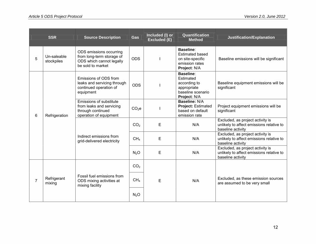
Article 5 ODS Project Protocol Version 2.0, June 2012
12
SSR Source Description Gas Included (I) or Excluded (E)
Quantification Method
Justification/Explanation
5 Un-saleable stockpiles
ODS emissions occurring from long-term storage of ODS which cannot legally be sold to market
ODS I
Baseline: Estimated based on site-specific emission rates Project: N/A
Baseline emissions will be significant
6 Refrigeration
Emissions of ODS from leaks and servicing through continued operation of equipment
ODS I
Baseline: Estimated according to appropriate baseline scenario Project: N/A
Baseline equipment emissions will be significant
Emissions of substitute from leaks and servicing through continued operation of equipment
CO2e I
Baseline: N/A Project: Estimated based on default emission rate
Project equipment emissions will be significant
Indirect emissions from grid-delivered electricity
CO2 E N/A Excluded, as project activity is unlikely to affect emissions relative to baseline activity
CH4 E N/A Excluded, as project activity is unlikely to affect emissions relative to baseline activity
N2O E N/A Excluded, as project activity is unlikely to affect emissions relative to baseline activity
7 Refrigerant mixing
Fossil fuel emissions from ODS mixing activities at mixing facility
CO2
E N/A Excluded, as these emission sources are assumed to be very small
CH4
N2O

Article 5 ODS Project Protocol Version 2.0, June 2012
13
SSR Source Description Gas Included (I) or Excluded (E)
Quantification Method
Justification/Explanation
8 Transport to destruction facility
Fossil fuel emissions from the vehicular and ocean transport of ODS from aggregation point to final destruction facility in the U.S.
CO2 I
Baseline: N/A Project: Estimated based on distance and weight transported
Project emissions will be small, and can be calculated using the default factor provided
CH4 E N/A Excluded, as this emission source is assumed to be very small
N2O E N/A Excluded, as this emission source is assumed to be very small
9 Destruction
Emissions of ODS from incomplete destruction at destruction facility
ODS I
Baseline: N/A Project: Estimated based on ODS destroyed, or included in default deduction
Project emissions will be small, and can be calculated using the default factor provided
Emissions from the oxidation of carbon contained in destroyed ODS
CO2 I
Baseline: N/A Project: Estimated based on ODS destroyed, or included in default deduction
Project emissions will be small, and can be calculated using the default factor provided
Fossil fuel emissions from the destruction of ODS at destruction facility
CO2 I
Baseline: N/A Project: Estimated based on ODS destroyed, or included in default deduction
Project emissions will be small, and can be calculated using the default factor provided
CH4 E N/A Excluded, as this emission source is assumed to be very small
N2O E N/A Excluded, as this emission source is assumed to be very small
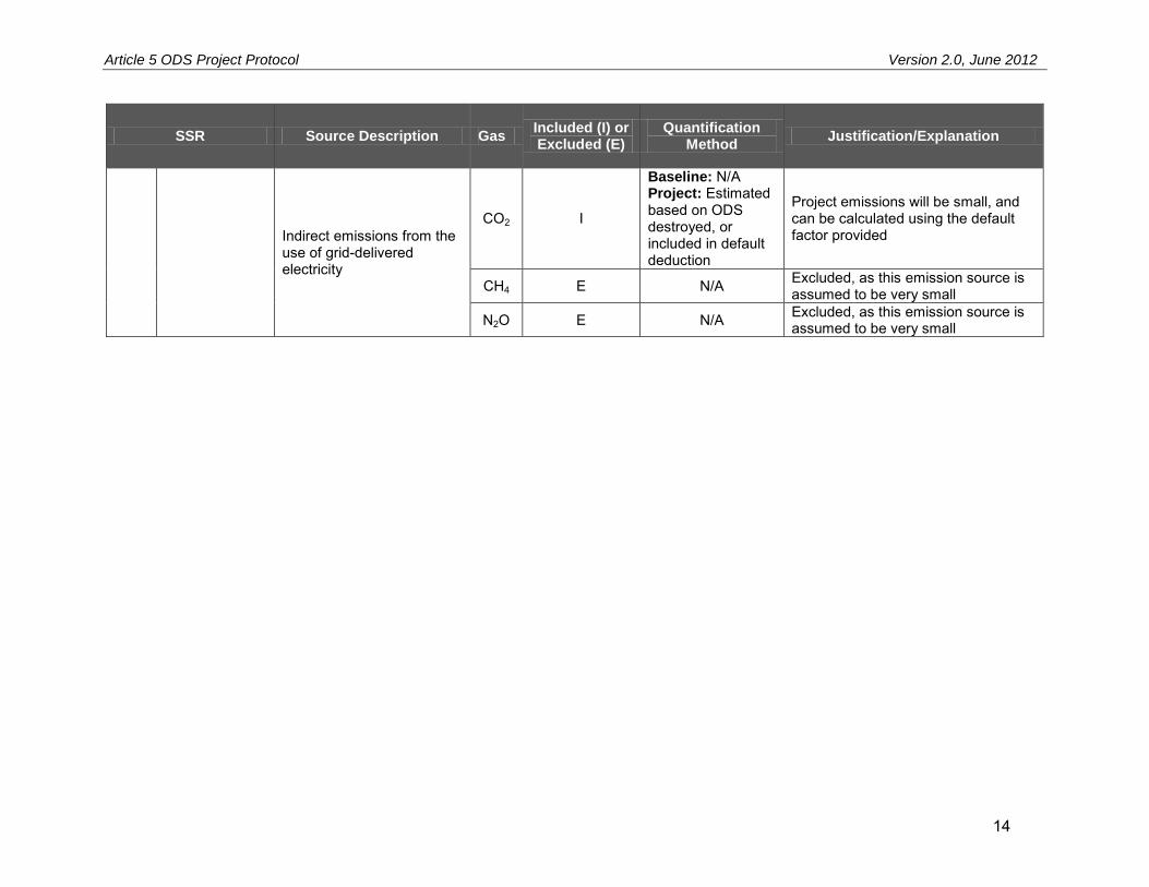
Article 5 ODS Project Protocol Version 2.0, June 2012
14
SSR Source Description Gas Included (I) or Excluded (E)
Quantification Method
Justification/Explanation
Indirect emissions from the use of grid-delivered electricity
CO2 I
Baseline: N/A Project: Estimated based on ODS destroyed, or included in default deduction
Project emissions will be small, and can be calculated using the default factor provided
CH4 E N/A Excluded, as this emission source is assumed to be very small
N2O E N/A Excluded, as this emission source is assumed to be very small

Article 5 ODS Project Protocol Version 2.0, June 2012
15
5 Quantifying GHG Emission Reductions GHG emission reductions from an ODS project are quantified by comparing actual project emissions to calculated baseline emissions. Baseline emissions are an estimate of the GHG emissions from sources within the GHG Assessment Boundary (see Section 4) that would have occurred in the absence of the ODS destruction project. Project emissions are actual GHG emissions that occur at sources within the GHG Assessment Boundary. Project emissions must be subtracted from the baseline emissions to quantify the project’s total net GHG emission reductions (Equation 5.1). A project may not span more than 12 months, and GHG emission reductions must be quantified and verified at least once for the entire project time length. The length of time over which GHG emission reductions are quantified and verified is called a “reporting period.” Project developers may choose to have multiple reporting periods within a project or a project time length shorter than 12 months, if desired. The quantification methods presented below are specified for a single reporting period, which may be less than or equal to the entire project time length. Equation 5.1. Total Emission Reductions
ttt PEBEER
Where,
Units
ERt = Total quantity of emission reductions during the reporting period tCO2e BEt = Total quantity of baseline emissions during the reporting period tCO2e PEt = Total quantity of project emissions during the reporting period tCO2e
5.1 Quantifying Baseline Emissions Total baseline emissions must be estimated by summing the calculated baseline emissions for all relevant SSRs (as indicated in Table 4.1) using Equation 5.3. This includes emissions from stockpiled refrigerants and end-of-life refrigerants that would have occurred over the ten-year crediting period. Note that emissions shall be quantified in pounds throughout this section and converted into metric tons in Equation 5.3 below. The Reserve has defined four different baselines for refrigerants in Article 5 countries. Table 5.1 identifies the refrigerant categories, and the associated applicable baseline scenario. The standardized baseline scenarios in Table 5.1 have been selected to provide a conservative estimation of baseline emissions from ODS refrigerants in Article 5 countries.

Article 5 ODS Project Protocol Version 2.0, June 2012
16
Table 5.1. Refrigerant Baseline Scenarios
Refrigerant Origin Baseline Scenario Applicable Annual Emission Rate
10-year Cumulative Emissions (%)
16
(ERrefr)
1. Privately held stockpiles of used ODS refrigerant that can legally be sold to the market
Use for recharge of existing refrigeration equipment
25%17 94%
2. Article 5 government stockpiles of ODS refrigerant that can legally be sold into the refrigerant market
Use for recharge of existing refrigeration equipment
25%17 94%
3. Article 5 government stockpiles of ODS refrigerants that cannot legally be sold into the refrigerant market
Continued storage
Site specific emission rate as documented (see Equation 5.2)
1-(1-ERstock)10
4. Used ODS refrigerant recovered from end-of-life equipment
End-of-life release to the atmosphere 100% 100%
The site specific emission rate for government stockpiles that cannot legally be sold into the refrigerant market shall be calculated according to Equation 5.2. Equation 5.2. Calculating Site-Specific Emission Rate
y
start
endistock
Q
QER
1
, 1
Where,
Units
ERstock,i = Average annual emission rate of refrigerant ODS i % Qend = Total quantity of ODS refrigerant i in government stockpile at time
of destruction lb ODS
Qstart = Total quantity of ODS refrigerant i in government stockpile at time of seizure
lb ODS
y = Time from seizure to destruction of ODS stockpile years
Equation 5.3 shall be used to calculate the baseline emissions that would have occurred over a ten-year horizon in the absence of the project activity, per the project crediting period limit (see Section 3.3). This equation requires the use of the applicable emission rate provided in Table 5.1 or calculated using Equation 5.2, and the ODS-specific GWP provided in Table 5.2.
16 10-year cumulative emissions = 1-(1-emission rate)10, or the percent of a given substance which will be released over ten years at a constant emission rate. 17 United Nations Environment Programme, Technology and Economic Assessment Panel. (2005). Report of the Task Force on Foam End-of-Life Issues.

Article 5 ODS Project Protocol Version 2.0, June 2012
17
Equation 5.3. Baseline Emissions
VR
GWPERQ
BE i
irefrirefrirefr
1
623.2204
,,,
Where,
Units
BE = Total quantity of refrigerant baseline emissions tCO2e Qrefr,,i = Total quantity of eligible, pure refrigerant ODS i destroyed by the
project lb ODS
ERrefr,i = 10-year cumulative emission rate of refrigerant ODS i (see Table 5.1) % GWPrefr,i = Global warming potential of refrigerant ODS i (see Table 5.2) lb CO2e/
lb ODS 2204.623 = Conversion from pounds to metric tons lb/t VR = Deduction for vapor composition risk (see Section 5.3) %
Table 5.2. Global Warming Potential of Eligible ODS Refrigerants
ODS Species Global Warming Potential
18
(CO2e)
CFC-11 4,750 CFC-12 10,900 CFC-113 6,130 CFC-114 10,000 CFC-115 7,370
If, during verification, the verification body cannot confirm that a portion of the ODS that was sent for destruction was eligible, this portion of the material shall be considered ineligible. This ineligible ODS shall be excluded from baseline emission calculations. The quantity of ineligible ODS sent for destruction shall be subtracted from Qrefr,i prior to the calculation of Equation 5.3 in order to calculate baseline emissions only for ODS that was confirmed to be eligible by the verification body. This quantity shall be determined by one of the following methods: Option A: Confirmed weight and composition
If the project developer can produce data that, based on the verifier’s professional judgment, confirm the weight and composition for the specific ODS that is deemed to be ineligible (or whose eligibility cannot be confirmed), these data shall be used to adjust the value of Qrefr,i accordingly. Option B: Default values
If sufficient data are not available to satisfy the Option A requirements, then the most conservative estimate of the weight and composition of the ineligible container of ODS shall be used. Specifically, the composition of the ineligible container of ODS shall be assumed to be 100 percent of the ODS species with the highest GWP based on the composition analysis, and the relevant container that was deemed ineligible shall be
18 United Nations Environment Programme, Technology and Economic Assessment Panel. (2005). Special report: Safeguarding the ozone layer and the global climate system: issues related to hydrofluorocarbons and perfluorocarbons.

Article 5 ODS Project Protocol Version 2.0, June 2012
18
assumed to have been full. If the project developer has only some of the data required for Option A (i.e. weight or composition, but not both), this may be used in place of the conservative assumptions above, as long as the data can be confirmed by the verification body. The resulting estimate of the weight of ineligible ODS shall be subtracted from the total weight of that ODS species destroyed in the project, not to exceed the actual amount of that ODS species destroyed. See Box 5.1 for an example of Option B.
Box 5.1. Applying Option B to Adjust for Ineligible ODS After Destruction This option shall be applied when multiple containers of ODS are combined into a single container for destruction, but the eligibility of the ODS in one or more of the original containers cannot be verified. Example:
A refrigerant aggregator receives shipments of three different containers (A, B, and C), which are combined into one project container (Z) for destruction. During verification, the project developer is unable to produce documentation to verify the eligibility of container C.
Original Containers from Point of Origin
Maximum Container Volume
Composition
A 1000 L unknown B 500 L unknown C 500 L unknown
Project container Weight Composition
Z 5000 lbs 50% CFC-11 50% CFC-12
Based on Option B above, the project developer must assume that the composition of container C was 100 percent CFC-12 and that the container was completely full. Using the temperature recorded on the composition analysis (62°F for this example), the maximum amount of ODS would be equal to the volume of the container (500 L) multiplied by the density of CFC-12 at 62°F (2.9553 lb/L), or 1,478 lbs. This amount is subtracted from the total amount of eligible ODS prior to quantification of emission reductions. Resulting eligible ODS: CFC-11: 2500 lbs CFC-12: 2500 – 1478 = 1022 lbs
5.2 Quantifying Project Emissions Project emissions are actual GHG emissions that occur within the GHG Assessment Boundary as a result of project activities. As shown in Equation 5.4, project emissions equal:
Emissions from substitute refrigerants, plus Emissions from the transportation of ODS, plus Emissions from the destruction of ODS
Note that emissions shall be quantified in pounds throughout this section and converted into metric tons in Equation 5.4 below.

Article 5 ODS Project Protocol Version 2.0, June 2012
19
Equation 5.4. Total Project Emissions
623.2204
DestTrSubPE
ref
t
Where,
Units
PEt = Total quantity of project emissions during the reporting period tCO2e Subref = Total emissions from substitute refrigerant lb CO2e Tr = Total emissions from transportation of ODS (calculated using
either the default value in Equation 5.6, or Equation 5.12) lb CO2e
Dest = Total emissions from the destruction process associated with destruction of ODS (calculated using either the default value in Equation 5.6, or Equation 5.7 through Equation 5.11)
lb CO2e
2204.623 = Conversion from pounds to metric tons lb/t
5.2.1 Calculating Project Emissions from the Use of CFC Substitutes
When refrigerant ODS are destroyed, continued demand for refrigeration will lead to the production and consumption of other refrigerant chemicals whose production is still legally allowed. Projects that destroy refrigerant from stockpiles that can legally be sold to market must therefore estimate the emissions associated with the non-CFC substitute chemicals that are assumed to be used in their place. Projects that destroy used refrigerant recovered from end-of-life equipment do not need to account for substitutes, as the destruction of this ODS does not increase the demand for substitute refrigerants. Similarly, projects that destroy government stockpiles that cannot legally be sold to the refrigerant market do not need to account for substitutes, as the destruction is not expected to increase use of substitute refrigerants. The point of origin of the ODS must be documented to support the selected baseline per Section 6.2. If the verifier can confirm that the point of origin is either end of life equipment tracked to location of ODS recovery or government stockpiles that cannot be legally sold, then Subrefr = 0. Equation 5.5 accounts for the emissions associated with the substitute refrigerants that will be used in place of destroyed ODS refrigerants. Like the destroyed ODS calculations in the baseline, substitute emissions shall also be estimated based on the projected emissions over the ten-year crediting period. Destroyed ODS refrigerants are assumed to be replaced by HFC-134a. A review of the literature indicates that HFC-134a and HC-600a are the dominant new refrigerants being used in place of ODS in Article 5 countries.19 However, no reliable, quantitative data could be identified on the relative market share of these refrigerants. As HFC-134a has a higher GWP, this assumption is therefore conservative. Project emissions from the use of non-CFC substitute refrigerants shall be calculated, as applicable, according to Equation 5.5.
19 United Nations Environment Programme, Technology and Economic Assessment Panel. (2006). Progress Report.

Article 5 ODS Project Protocol Version 2.0, June 2012
20
Equation 5.5. Calculating Project Emissions from the Use of Non-ODS Refrigerants
i
irefrrefr QSub 143077.0,
Where,
Units
Sub,refr = Total quantity of project refrigerant substitute emissions lb CO2e Qrefr,i = Total quantity of eligible, pure refrigerant ODS i destroyed lb 0.77 = Leak rate of HFC-134a (13.7% per year)20 % (0-1) 1430 = Global warming potential of HFC-134a lb CO2e/ lb sub
5.2.2 Calculating Default Project Emissions from ODS Destruction and Transportation
Projects must account for emissions that result from the transportation and destruction of ODS. Because these emission sources are both individually and in aggregate very small, the Reserve has developed a default emission factor for ODS projects based on conservative assumptions and the SSRs outlined in Table 4.1.21 The emission factor shall be equal to 7.5 pounds CO2e per pound of ODS refrigerant destroyed. This emission factor aggregates both transportation and destruction emissions. Project developers have the option of using the default emission factor, or using the in Sections 5.2.3 and 5.2.4 to calculate project-specific emissions. Equation 5.6 shall be used to calculate ODS transportation and destruction emissions if default emission factors are used. Equation 5.6. Project Emissions from Transportation and Destruction Using the Default Emission Factors
5.7 iQDestTr
Where,
Units
Tr + Dest = Total emissions from ODS transportation and destruction, as calculated using default emission factors
lb CO2e
Qi = Total quantity of refrigerant i ODS sent for destruction, including eligible and ineligible material
lb ODS
7.5 = Default emission factor for transportation and destruction of ODS lb CO2e/ lb ODS
5.2.3 Calculating Site-Specific Project Emissions from ODS Destruction
Under this protocol, ODS must be destroyed at destruction facilities which demonstrate compliance with the TEAP recommendations.22 These facilities demonstrate their ability to achieve destruction efficiencies upwards of 99.99 percent for substances with thermal stability ratings higher than the ODS included herein.23 Associated with the operation of these facilities are emissions of CO2 from the fuel and electricity used to power the destruction, emissions of un-combusted ODS, and emissions of CO2 from the oxidation of ODS. Equation 5.7 through 20 United Nations Environment Programme, Technology and Economic Assessment Panel. (2006). Report of the Refrigeration, Air Conditioning and Heat Pumps Technical Options Committee. 21 See Appendix D for a summary of how the default emission factor was derived. 22 TEAP, http://uneptie.org/ozonaction/topics/disposal.htm. 23 ICF International. (2009). ODS Destruction in the United States of America and Abroad. U.S. EPA Stratospheric Protection Division.

Article 5 ODS Project Protocol Version 2.0, June 2012
21
Equation 5.9 provide guidance on calculating emissions from ODS destruction in cases where project developers opt not to use the default factors outlined in Section 5.2.3. Equation 5.7. Project Emissions from the Destruction of ODS
2COemissionsdestdest ODSODSELFFDest
Where,
Units
Dest = Total emissions from the destruction of ODS lb CO2e FFdest = Total emissions from fossil fuel used in the destruction facility
(Equation 5.8) lb CO2
ELdest = Total indirect emissions from grid electricity used at the destruction facility (Equation 5.9)
lb CO2
ODSemissions = Total emissions of un-destroyed ODS (Equation 5.10) lb CO2e ODSCO2 = Total emissions of CO2 from ODS oxidation (Equation 5.11) lb CO2
Equation 5.8. Fossil Fuel Emissions from the Destruction of ODS
454.0
,,
k
kFFkPR
dest
EFFF
FF
Where,
Units
FFdest = Total carbon dioxide emissions from the destruction of fossil fuel used to destroy ODS
lb CO2
FFPR,k = Total fossil fuel k used to destroy ODS volume fossil fuel EFFF,k = Fuel specific emission factor (see Appendix D) kg CO2/ volume
fossil fuel 0.454 = Conversion from kg to lb of CO2 kg CO2/ lb CO2
Equation 5.9. Electricity Emissions from the Destruction of ODS
ELPRdest EFELEL
Where,
Units
ELdest = Total carbon dioxide emissions from the consumption of electricity from the grid used to destroy ODS
lb CO2
ELPR = Total electricity consumed to destroy ODS MWh EFEL = Carbon emission factor for electricity used24 lb CO2/ MWh
24 Refer to the version of the EPA eGRID that most closely corresponds to the time period during which the electricity was used. Project shall use the annual total output emission rates for the subregion where the destruction facility is located, not the non-baseload output emission rates. The eGRID tables are available at http://www.epa.gov/cleanenergy/energy-resources/egrid/index.html.

Article 5 ODS Project Protocol Version 2.0, June 2012
22
Equation 5.10. Calculating Project Emissions from ODS Not Destroyed
i
iirefremissions GWPQODS 0001.0,
Where,
Units
ODSemissions = Total emissions of un-destroyed ODS lb CO2e Qrefr,i = Total quantity of refrigerant ODS i sent for destruction lb ODS 0.0001 = Maximum allowable portion of ODS fed to destruction that is not
destroyed (0.01%)
GWPi = Global warming potential of ODS i (see Table 5.2) lb CO2e/ lb ODS
Equation 5.11. Calculating Project Emissions of CO2 from the Oxidation of ODS
i
iirefrCO CRQODS12
449999.0,2
Where,
Units
ODSCO2 = Total emissions of CO2 from ODS oxidation lb CO2 Qrefr,i = Total quantity of refrigerant ODS i sent for destruction lb ODS 0.9999 = Minimum destruction efficiency of destruction facility (99.99%) CRi = Carbon ratio of ODS i
CFC-11: 12/137 CFC-12: 12/121 CFC-113: 24/187 CFC-114: 24/171 CFC-115: 24/154
MW C/ MW ODS
44/12 = Ratio of molecular weight of CO2 to C MW CO2/ MW C
5.2.4 Calculating Site-Specific Project Emissions from ODS Transportation
As part of any ODS destruction project, ODS must be transported from the Article 5 origin country to the U.S. Further, upon arrival in the U.S., ODS must be transported from aggregators to destruction facilities. Emissions from both of these activities must be accounted for under this protocol using either Equation 5.6 or Equation 5.12. Equation 5.12 provides guidance on calculating site-specific CO2 emissions associated with the transport of ODS. Emissions shall be calculated for each leg of the transportation process separately, and then summed according to Equation 5.12 below.
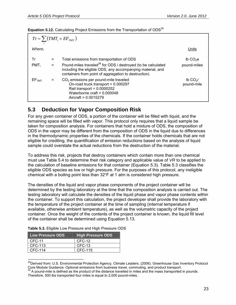
Article 5 ODS Project Protocol Version 2.0, June 2012
23
Equation 5.12. Calculating Project Emissions from the Transportation of ODS25
i
TMTi EFTMTTr
Where,
Units
Tr = Total emissions from transportation of ODS lb CO2e PMTi = Pound-miles traveled26 for ODS i destroyed (to be calculated
including the eligible ODS, any accompanying material, and containers from point of aggregation to destruction)
pound-miles
EFTMT = CO2 emissions per pound-mile traveled On-road truck transport = 0.000297 Rail transport = 0.0000252 Waterborne craft = 0.000048 Aircraft = 0.0015279
lb CO2/ pound-mile
5.3 Deduction for Vapor Composition Risk For any given container of ODS, a portion of the container will be filled with liquid, and the remaining space will be filled with vapor. This protocol only requires that a liquid sample be taken for composition analysis. For containers that hold a mixture of ODS, the composition of ODS in the vapor may be different from the composition of ODS in the liquid due to differences in the thermodynamic properties of the chemicals. If the container holds chemicals that are not eligible for crediting, the quantification of emission reductions based on the analysis of liquid sample could overstate the actual reductions from the destruction of the material. To address this risk, projects that destroy containers which contain more than one chemical must use Table 5.4 to determine their risk category and applicable value of VR to be applied to the calculation of baseline emissions for that container (Equation 5.3). Table 5.3 classifies the eligible ODS species as low or high pressure. For the purposes of this protocol, any ineligible chemical with a boiling point less than 32°F at 1 atm is considered high pressure. The densities of the liquid and vapor phase components of the project container will be determined by the testing laboratory at the time that the composition analysis is carried out. The testing laboratory will calculate the densities of the liquid phase and vapor phase contents within the container. To support this calculation, the project developer shall provide the laboratory with the temperature of the project container at the time of sampling (internal temperature if available, otherwise ambient temperature), as well as the volumetric capacity of the project container. Once the weight of the contents of the project container is known, the liquid fill level of the container shall be determined using Equation 5.13. Table 5.3. Eligible Low Pressure and High Pressure ODS
Low Pressure ODS High Pressure ODS
CFC-11 CFC-12 CFC-113 CFC-13 CFC-114 CFC-115
25Derived from: U.S. Environmental Protection Agency, Climate Leaders. (2008). Greenhouse Gas Inventory Protocol Core Module Guidance: Optional emissions from business travel, commuting, and product transport. 26 A pound-mile is defined as the product of the distance travelled in miles and the mass transported in pounds. Therefore, 500 lbs transported four miles is equal to 2,000 pound-miles.

Article 5 ODS Project Protocol Version 2.0, June 2012
24
Table 5.4. Determining the Deduction for Vapor Composition Risk
If the value of Fillliquid is:
AND the concentration of eligible low
pressure ODS is:
AND the concentration of ineligible high
pressure chemical is:
Then the vapor risk deduction factor (VR) for that container shall be:
> 0.70 N/A N/A 0 0.50 – 0.70 > 1% > 10% 0.02
< 0.50 > 1% > 5% 0.05 The presence of eligible, high-pressure ODS may mitigate the risk of over-crediting, so there are two scenarios where a container is exempt from a deduction otherwise required in Table 5.4:
1. The container holds an eligible, high-pressure ODS (in any concentration) which has a lower boiling point than the ineligible, high-pressure chemical, or
2. The container holds an eligible, high-pressure ODS in a concentration greater than that of the ineligible, high-pressure chemical.
If the container holds multiple eligible, high-pressure ODS, the applicability of the above scenarios will be determined based on the ODS with the highest percent concentration. If the container holds multiple ineligible, high-pressure chemicals, the applicability of the above scenarios will be determined based on the chemical with the highest percent concentration. This deduction applies to both mixed and non-mixed ODS projects as defined in Section 6.6. Equation 5.13. Determining Liquid Fill Level in Project Container
containervaporliquid
containervapordestroyed
liquidV
VMFill
Where,
Units
Fillliquid = Fill level of the liquid in the project container fraction
Vcontainer = Total volume of the project container gal
Mdestroyed = Total mass of the contents of the project container lbs
ρliquid = Modeled density of the liquid material in the project container at the measured temperature
lbs/gal
ρvapor = Modeled density of the vapor material in the project container at the measured temperature
lbs/gal

Article 5 ODS Project Protocol Version 2.0, June 2012
25
6 Project Monitoring and Operations The Reserve requires a Monitoring and Operations Plan to be established for all monitoring, operations, and reporting activities associated with ODS destruction projects. The Monitoring and Operations Plan will serve as the basis for verification bodies to confirm that the monitoring, operations, and reporting requirements in this section and Section 7 have been and will continue to be met, and that consistent, rigorous monitoring and record-keeping is ongoing for the project. The Monitoring and Operations Plan must cover all aspects of monitoring and reporting contained in this protocol and must specify how data for all relevant parameters in Table 6.2 will be collected and recorded. At a minimum the Monitoring and Operations Plan shall stipulate the frequency of data acquisition; a record keeping plan (see Section 7.2 for minimum record keeping requirements); and the role of individuals performing each specific monitoring and operational activity. The Monitoring and Operations Plan shall contain a project diagram that illustrates the project ODS point(s) of origin, any reclamation facilities used, information on ODS transportation mode and transportation companies, mixing/sampling facilities, testing laboratories, and the destruction facility (see Appendix F for a sample project diagram). The Monitoring and Operations Plan should also include QA/QC provisions to ensure that operations, data acquisition and ODS analyses are carried out consistently and with precision. In addition, the Monitoring and Operations Plan must stipulate data management systems and coordination of data between ODS aggregators, project developers, and destruction facilities. Project developers are responsible for monitoring the performance of the project and ensuring that there is no double-counting of GHG reductions associated with ODS destruction. To achieve this, the Monitoring and Operations Plan must also include a description of how data will be provided to the Reserve ODS tracking system (see Section 6.1). Finally, the Monitoring and Operations Plan must include procedures that the project developer will follow to ascertain and demonstrate that the project at all times passes the Legal Requirement Test (Section 3.4.1).
6.1 Reserve ODS Tracking System For the purposes of ensuring the integrity of ODS destruction projects, the Reserve maintains an online database of all destruction activities for which CRTs are registered and issued. Entries into this system within the Reserve software must be made by the project developer prior to the beginning of verification activities relating to confirming that reductions have not been claimed by other parties for the destruction activity in question.27 All projects are required to have one or more Certificate(s) of Destruction accounting for all eligible ODS destroyed as part of the project. The following information shall be entered by the project developer into the Reserve software from the Certificate(s) of Destruction issued by the destruction facility, and a copy of the certificate(s) must be provided to the project verifier:
Project developer (project account holder) Destruction Facility Generator name
27 Other verification activities (such as site visits) may commence prior to submission of information into the ODS tracking system.

Article 5 ODS Project Protocol Version 2.0, June 2012
26
Certificate of Destruction ID number Start destruction date End destruction date Total weight of material destroyed (including eligible and ineligible material)
6.2 Point of Origin and Import Documentation Requirements Project developers are responsible for collecting data on the point of origin for each quantity of ODS, as defined in Table 6.1. The project developer must maintain detailed acquisition records of all quantities of ODS destroyed by the project. Table 6.1. Identification of Point of Origin ODS Point of Origin 10-year Cumulative
Emissions (%)1
1. Virgin ODS stockpiles Location of stockpile 94% or site-specific emission rate (see Section 5.1)
2. Used ODS stockpiled prior to February 3, 2010
Location of stockpile 94% or site specific emission rate (see Section 5.1)
3. Used ODS in quantities less than 500 lbs
Location where ODS is first aggregated to greater than 500 lbs
94%
4. Used ODS in quantities greater than 500 lbs
Site of installation from which ODS is removed
94%
5. Used ODS of any quantity recovered from end-of-life equipment
Location where ODS is recovered from end-of-life equipment
100%
1 This information is provided to illustrate the connection between point of origin and the cumulative emission rate used to calculate baseline emissions. See Table 5.1 for more details on these emission rates and related baseline scenarios. Project developers must be able to document the point of origin for all ODS that will be included in the project as defined in the table above. For destroyed ODS where the point of origin is a reservoir-style stockpile (i.e. it was not sealed), the date on which the ODS was stockpiled is established using “first-in/first-out” accounting. Specifically, the date on which a quantity of ODS was “stockpiled” is defined as the furthest date in the past on which the quantity of ODS contained in the reservoir was greater than or equal to the total quantity of all ODS removed from the reservoir since that date (including any ODS removed and destroyed as part of the project). The date must be established using management systems and logs that verify the quantities of ODS placed into and removed from the reservoir throughout the relevant period. Provided these elements are met, and the stockpile follows the “first-in/first-out” accounting, the date on which a quantity of ODS was stockpiled may be established. For virgin stockpiles, documentation of the point of origin must be generated at the time material is placed at the stockpile location and every time material is added to the stockpile. For used stockpiles, documentation must confirm that the stockpile has been stored at the point of origin prior to February 3, 2010. For ODS recovered by service technicians in individual quantities less than 500 pounds, the point of origin is defined as the facility where two or more containers were combined and exceeded 500 pounds in a single container. Those handling quantities less than 500 pounds in a single container need not provide the documentation required below. However, once smaller

Article 5 ODS Project Protocol Version 2.0, June 2012
27
quantities are aggregated and exceed 500 pounds in a single container, tracking is required at that location and point in time forward. For containers of ODS greater than 500 pounds (determined as the weight of eligible ODS within a single container), the project developer must provide documentation as to the origin of the ODS within that container and when it was recovered. If it is shown that, prior to aggregation in the project container, the ODS was contained as a quantity greater than 500 pounds, then the documentation must extend back to this previous container and its point of origin. The project developer must provide documentation tracking the ODS back to a point in time and location where it was either a) contained or recovered as a quantity of less than 500 pounds, or b) recovered by a service technician as a quantity of greater than 500 pounds. For ODS recovered from end-of-life equipment, the project developer must provide documentation to confirm that the ODS was recovered at the point of origin and that the equipment was disposed of/decommissioned after the ODS was recovered. It may not be possible to document the exact time the ODS was recovered from all equipment (e.g. at a reclamation facility processing large numbers of appliances), but the verifier must confirm that the inventory and activity logs support the quantity of ODS being destroyed for that reporting period. All data must be generated at the point of origin. Documentation of the point of origin of ODS shall include the following:
Facility name and physical address For quantities greater than 500 pounds, identification of the system by serial number, if
available, or description, location, and function, if serial number is unavailable Serial or ID number of containers used for storage and transport
In addition to establishing the point of origin, for destroyed virgin ODS project developers must also provide government documentation that the virgin ODS was produced prior to the production phase-out in that country, and that it has not been produced illegally. This may be in the form of an audit conducted by or for the government that identifies the stockpile and entity holding it, or correspondence regarding the stockpile from, or submitted to, a government agency. Verifiers may request independent confirmation of the asserted documentation from government officials or their representatives. The project developer shall also document the process by which the ODS was obtained and imported. Project developers must maintain a full record of the U.S. EPA and/or U.S. Customs import process28 for verification purposes. The record must include the following:
Commercial invoice showing transfer of ownership of the ODS from the owner in the source country to the project developer
Shipping manifests or ocean bills of lading (where appropriate) showing the country of export
U.S. Customs import declaration showing the product being imported into the U.S Copy of Class 1 ODS import report showing that product has been imported for
destruction
28 U.S. Code of Federal Regulations. Protection of Stratospheric Ozone. 40 CFR 82.
Article 5 ODS Project Protocol Version 2.0, June 2012
28
For imports of used ODS, copy of EPA non-objection notice that corresponds to the import of used ODS (this non-objection notice is not required for imports of virgin Class 1 substance for destruction)
Source of ODS: stockpile or end-of-life Serial or ID numbers of containers used for storage and transport Mode of transport, distance travelled prior to arriving at a U.S. port of entry, and net
weight of ODS and containers transported
6.3 Custody and Ownership Documentation Requirements In conjunction with establishing the point of origin and importation process for each quantity of ODS, project developers must also document the custody and ownership of ODS. These records shall include names, addresses, and contact information of persons buying/selling the material for destruction and the quantity of the material (the combined mass of refrigerant and contaminants) bought/sold. Such records may include Purchase Orders, Purchase Agreements, packing lists, bills of lading, lab test results, transfer container information, receiving inspections, freight bills, transactional payment information, and any other type of information that will support previous ownership of the material and the transfer of that ownership to the project developer. The verification body will review these records and will perform other tests necessary to authenticate the previous owners of the material and the physical transfer of the product and the title transfer of ownership rights of all emissions and emission reductions associated with destroyed ODS to the project developer, as documented through contracts, agreements, or other legal documents. No GHG credits may be issued under this protocol for ODS where ownership cannot be established. The transfer of custody may be established using the following documentation, as appropriate:
Tax ID, or other applicable identifier, of transferor and transferee Bill of lading (where appropriate) Date of transfer of custody Serial or ID numbers of all containers containing ODS (received and delivered) Weight of all containers containing ODS (received and delivered) Distance and mode of transportation used to move ODS (truck, rail or air)
6.4 ODS Composition and Quantity Analysis Requirements The requirements of this section must be followed to determine the quantities of ODS refrigerants. Prior to destruction, the precise mass and composition of ODS to be destroyed must be determined. The following analysis must be conducted: Mass shall be determined by individually measuring the weight of each container of ODS: (1) when it is full prior to destruction; and (2) after it has been emptied and the contents have been fully purged and destroyed. The mass of ODS and any contaminants is equal to the difference between the full and empty weight, as measured. The following requirements must be met for the measurement of each container:
1. A single scale must be used for generating both the full and empty weight tickets at the destruction facility
2. The scale used must have its calibration tested quarterly by a licensed service company, using certified test weights. A scale is considered calibrated if it is within the maintenance tolerance of the relevant National Institute of Standards and Technology

Article 5 ODS Project Protocol Version 2.0, June 2012
29
(NIST) Handbook 44 accuracy class. If a scale is found to be outside of this tolerance, it must be recalibrated
3. The full weight must be measured no more than two days prior to commencement of destruction per the Certificate of Destruction
4. The empty weight must be measured no more than two days after the conclusion of destruction per the Certificate of Destruction
Composition and concentration of ODS and contaminants shall be established for each individual container by taking a sample from each container of ODS and having it analyzed for composition and concentration at an Air-Conditioning, Heating and Refrigeration Institute (AHRI) certified laboratory using the AHRI 700-200629 standard, or its successor. The laboratory performing the composition analysis must not be affiliated with the project developer or the project beyond performing these services. The following requirements must be met for each sample:
1. The sample must be taken while ODS is in the possession of the company that will destroy the ODS
2. Samples must be taken by a technician unaffiliated with the project developer30 3. Samples must be taken with a clean, fully evacuated sample bottle that meets applicable
U.S. Department of Transportation (DOT) requirements with a minimum capacity of one pound
4. The technician must ensure that the sample is representative of the contents of the container. All valves between the interior of the container and the sample port must be opened for a minimum of 15 minutes before the sample is taken
5. Each sample must be taken in liquid state 6. A minimum sample size of one pound must be drawn for each sample 7. Each sample must be individually labeled and tracked according to the container from
which it was taken, and the following information recorded: a) Time and date of sample b) Name of project developer c) Name of technician taking sample d) Employer of technician taking sample e) Volume of container from which sample was extracted f) Ambient air temperature at time of sampling31
8. Chain of custody from point of sampling to AHRI laboratory for each sample must be documented by paper bills of lading or electronic, third-party tracking that includes proof of delivery (e.g. FedEx, UPS)
All project samples shall be analyzed using AHRI 700-2006 or its successor to confirm the mass percentage and identity of each component of the sample. The analysis shall provide:
1. Identification of the refrigerant 2. Purity (%) of the ODS mixture by weight using gas chromatography 3. Moisture level in parts per million: the moisture content of each sample must be less
than 75 percent of the saturation point for the ODS taking into account the temperature 29 AHRI. (2006). Standard 700-2006: Standard for Specifications for Fluorocarbon Refrigerants. 30 For instances where the project developer is the destruction facility itself, an outside technician must be employed for sample taking. 31 Projects that destroy ODS prior to the adoption date of this protocol may use proxy data from NOAA recording stations in the area.

Article 5 ODS Project Protocol Version 2.0, June 2012
30
recorded at the time the sample was taken. For containers that hold mixed ODS, the sample’s saturation point shall be assumed to be that of the ODS species in the mixture with the lowest saturation point that is at least 10 percent of the mixture by mass
4. Analysis of high boiling residue, which must be less than 10 percent by mass 5. Analysis of other ODS in the case of mixtures of ODS and their percentage by mass
If any of the requirements above are not met, no GHG reductions may be verified for the ODS from that container. If a sample is tested and does not meet one of the requirements as defined above, the project developer may elect to have the material re-sampled and re-analyzed. While there is no limit to the number of samples that may be taken, the analysis results of all samples must be disclosed to the verification body, and the most conservative composition analysis from these samples shall be used for the quantification. If a project developer elects to have the material dried prior to resampling, the previous samples (prior to drying) may be disregarded. Note that the threshold for moisture saturation will be difficult to achieve at very low temperatures, and it is recommended that sampling not occur if the ambient air temperature is below 32°F. Project developers may sample for moisture content and perform any necessary de-watering prior to the required sampling and laboratory analysis. If the container holds non-mixed ODS (defined as greater than 90 percent composition of a single ODS species) no further information or sampling is required to determine the mass and composition of the ODS. If the container holds mixed ODS, which is defined as less than 90 percent composition of a single ODS species, the project developer must meet additional requirements as provided in Section 6.4.1.
6.4.1 Analysis of Mixed ODS
If a container holds mixed ODS, its contents must be processed and measured for composition and concentration according to the requirements of this section (in addition to the requirements of Section 6.4). The sampling required under this section may be conducted at the final destruction facility or prior to delivery to the destruction facility. However, the circulation and sampling activities must be conducted by a third-party organization (i.e. not the project developer), and by individuals who have been properly trained for the functions they perform. Circulation and sampling may be conducted at the project developer’s facility, but all activities must be directed by a properly trained and contracted third-party. The project’s Monitoring and Operations Plan must specify the procedures by which mixed ODS are analyzed. If the mixing and sampling are conducted at the destruction facility, then the most conservative result of the two samples shall be used to satisfy the requirements of Section 6.4. If the mixing and sampling do not occur at the destruction facility, then the most conservative composition analysis from the mixing facility samples shall be used for the quantification of emission reductions. The composition and concentration of ODS on a mass basis of each container shall be determined using the results of the analysis of this section. The results of the composition analysis in Section 6.4 shall be used by verifiers to confirm that the destroyed ODS was in fact the same ODS that is sampled under these requirements. The ODS mixture must be circulated in a container that meets all of the following criteria:

Article 5 ODS Project Protocol Version 2.0, June 2012
31
1. The container has no solid interior obstructions32 2. The container was fully evacuated prior to filling 3. The container must have mixing ports to circulate liquid and gas phase ODS 4. The liquid port intake shall be at the bottom of the container, and the vapor port intake
shall be at the top of the container. For horizontally-oriented mixing containers, the intakes shall be located in the middle third of the container
5. The container and associated equipment can circulate the mixture via a closed loop system from the liquid port to the vapor port
If the original mixed ODS container does not meet these requirements, the mixed ODS must be transferred into a temporary holding tank or container that meets all of the above criteria. The weight of the contents placed into the temporary container shall be calculated and recorded. During transfer of ODS into and out of the temporary container, ODS shall be recovered to the vacuum levels required by the U.S. EPA for the ODS (see 40 CFR 82.156).33 Once the mixed ODS is in a container or temporary storage unit that meets the criteria above, circulation of mixed ODS must be conducted as follows:
1. Liquid mixture shall be circulated from the liquid port to the vapor port 2. A volume of the mixture equal to two times the volume in the container shall be
circulated 3. Circulation must occur at a rate of at least 30 gallons/minute. Alternatively, circulation
may occur at a rate that is less than 30 gallons/minute, as long as criterion #2 is achieved within the first six hours of mixing
4. Start and end times shall be recorded Within 30 minutes of the completion of circulation, a minimum of two samples shall be taken from the bottom liquid port according to the procedures in Section 6.4. Both samples shall be analyzed at an AHRI-approved laboratory per the requirements of Section 6.4. The mass composition and concentration of the mixed ODS shall be equal to the lesser of the two GWP-weighted concentrations. If a temporary holding tank is used, after drawing the sample, the holding tank shall be emptied back into the original container for transport to the destruction location.
6.5 Destruction Facility Requirements Destruction of ODS must occur at a facility that meets all of the guidelines provided in Appendix C and in the TEAP Task Force on Destruction Technologies.34 Any destruction facility that is regulated by U.S. EPA as a RCRA-permitted HWC is automatically considered a qualifying destruction facility under this protocol; no further testing for TEAP compliance is required. Non-RCRA permitted facilities may also be deemed qualifying destruction facilities if they meet the pertinent guidelines reproduced in Appendix C. Destruction facilities must provide third-party certified results indicating that the facility meets all performance criteria set forth in Appendix C. Following the initial performance testing, project developers must demonstrate that the facility has conducted comprehensive performance testing at least every three years to validate
32 Mesh baffles or other interior structures that do not impede the flow of ODS are acceptable. 33 U.S. EPA. Required Levels of Evacuation. Retrieved December 21, 2009, from http://www.epa.gov/Ozone/title6/608/608evtab.html. 34 Available at http://www.uneptie.org/ozonaction/topics/disposal.htm.

Article 5 ODS Project Protocol Version 2.0, June 2012
32
compliance with the TEAP DRE and emissions limits as reproduced in Appendix C. No ODS destruction credits shall be issued for destruction that occurs at a facility that has failed to undergo comprehensive performance testing according to the required schedule, or has failed to meet the requirements of such performance testing. At the time of ODS destruction, all destruction facilities must have a valid Title V air permit, if applicable, and any other air or water permits required by local, state, or federal law to destroy ODS. Facilities must document compliance with all monitoring and operational requirements associated with the destruction of ODS materials, as dictated by these permits, including emission limits, calibration schedules, and personnel training. Any upsets or exceedances of emission limits must be managed in keeping with an authorized startup, shutdown, and malfunction plan. Non-RCRA facilities must document operation consistent with the TEAP requirements, as defined in this section and Appendix C. Operating parameters of the destruction unit while destroying ODS material shall be monitored and recorded as described in the Code of Good Housekeeping35 approved by the Montreal Protocol. This data shall be used in the verification process to demonstrate that during the destruction process, the destruction unit was operating similarly to the period in which the DRE36 was calculated. The DRE is determined by using the Comprehensive Performance Test (CPT)37 as a proxy for DRE and is disclosed to the public in the destruction facility’s Title V operating permit. To monitor that the destruction facility operates in accordance with applicable regulations and within the parameters recorded during DRE testing, the following parameters must be tracked continuously during the entire ODS destruction process:
The ODS feed rate The amount and type of consumables used in the process (not required if default project
emission factor for transportation and destruction is used) The amount of electricity and amount and type of fuel consumed by the destruction unit
(not required if default project emission factor for transportation and destruction is used) Operating temperature and pressure of the destruction unit during ODS destruction Effluent discharges measured in terms of water and pH levels Continuous emissions monitoring system (CEMS) data on the emissions of carbon
monoxide during ODS destruction The project developer must maintain records of all these parameters for review during the verification process. Destruction facilities shall provide a valid Certificate of Destruction for all ODS destroyed. The Certificate of Destruction shall include:
Project developer (project account holder) Destruction facility Generator name Certificate of Destruction ID number
35 TEAP. (2006). Code of Good Housekeeping. Handbook for the Montreal Protocol on Substances that Deplete the Ozone Layer - 7
th Edition.
36 DRE disclosed in Title V operating permit. 37 CPT must have been conducted with a less combustible chemical than the ODS in question.

Article 5 ODS Project Protocol Version 2.0, June 2012
33
Serial, tracking or ID Number of all containers for which ODS destruction occurred Owner of destroyed ODS Weight of material destroyed from each container (including eligible and ineligible
material) Type of material destroyed from each container (including all materials listed on
laboratory analysis of ODS composition from sampling at the destruction facility) Start destruction date End destruction date
6.6 Monitoring Parameters Prescribed monitoring parameters necessary to calculate baseline and project emissions are provided in Table 6.2 below. In addition to the parameters below that are used in the calculations provided in Section 5, project developers are responsible for maintaining all records required under Sections 5.3 through 7.

Article 5 ODS Project Protocol Version 2.0, June 2012
34
Table 6.2. ODS Project Monitoring Parameters
Eq. # Parameter Description Data Unit Measurement Frequency
Calculated (C) Measured (M) Reference (R)
Operating Records (O)
Comment
Legal Requirement Test For each reporting period Must be monitored and determined
for each reporting period
Mass of ODS (or ODS mixture) in each container Per container M Must be determined for each
container destroyed
Concentration of ODS (or ODS mixture) in each container Per container M Must be determined for each
container destroyed
Equation 5.1 ERt
Total quantity of emission reductions during the reporting period
tCO2e For each reporting period C
Equation 5.1, Equation 5.3 BEt
Total quantity of baseline emissions during the reporting period tCO2e For each
reporting period C
Equation 5.1, Equation 5.4 PEt
Total quantity of project emissions during the reporting period tCO2e For each
reporting period C
Equation 5.2 ERstock,i Average annual emission rate of refrigerant ODS i % For each
reporting period C
Equation 5.2 Qend Total quantity of ODS refrigerant i in government stockpile at time of destruction
lb ODS For each reporting period M
Equation 5.2 Qstart Total quantity of ODS refrigerant i in government stockpile at time of seizure
lb ODS For each reporting period M
Equation 5.3, Equation 5.5, Equation 5.10, Equation 5.11
Qrefr,i Total quantity of eligible refrigerant ODS i destroyed lb ODS For each
reporting period M
Equation 5.3 ERrefr,i 10-year cumulative emission rate of refrigerant ODS i % N/A R See Table 5.1
Equation 5.3, Equation 5.10 GWPrefr,i
Global warming potential of refrigerant ODS i
lb CO2e/ lb ODS N/A R See Table 5.2
Equation 5.3 VR Vapor risk deduction factor % (0-1) For each reporting period R See Table 5.4
Equation 5.4, Equation 5.5 Sub,ref
Total emissions from substitute refrigerant lb CO2e For each
reporting period C

Article 5 ODS Project Protocol Version 2.0, June 2012
35
Eq. # Parameter Description Data Unit Measurement Frequency
Calculated (C) Measured (M) Reference (R)
Operating Records (O)
Comment
Equation 5.4, Equation 5.6, Equation 5.12
Tr Total emissions from transportation of ODS lb CO2e For each
reporting period C May be calculated using default or using project specific inputs
Equation 5.4, Equation 5.6, Equation 5.7
Dest Total emissions from the destruction process associated with destruction of ODS
lb CO2e For each reporting period C May be calculated using default or
using project specific inputs
Equation 5.6 Qi Total quantity of refrigerant i sent for destruction, including eligible and ineligible material
lb ODS For each reporting period M
Equation 5.7, Equation 5.8 FFdest
Total emissions from fossil fuel used in the destruction facility
lb CO2e For each reporting period C
Use only if calculating site-specific project emissions from ODS destruction
Equation 5.7, Equation 5.9 ELdest
Total emissions from grid electricity at the destruction facility lb CO2e For each
reporting period C Use only if calculating site-specific project emissions from ODS destruction
Equation 5.7, Equation 5.10 ODSemissions
Total emissions of un-destroyed ODS lb CO2e For each
reporting period C Use only if calculating site-specific project emissions from ODS destruction
Equation 5.7, Equation 5.11 ODSCO2
Total emissions of CO2 from ODS oxidation lb CO2
For each reporting period C
Use only if calculating site-specific project emissions from ODS destruction
Equation 5.8 FFPR,k Total fossil fuel k used to destroy ODS lb CO2e For each
reporting period M Use only if calculating site-specific project emissions from ODS destruction
Equation 5.8 EFFF,k Fuel specific emission factor kg CO2/ volume
fuel N/A R
Use only if calculating site-specific project emissions from ODS destruction
Equation 5.9 ELPR Total electricity consumed to destroy ODS MWh For each
reporting period M Use only if calculating site-specific project emissions from ODS destruction
Equation 5.9 EFEL Carbon emission factor for electricity used
lb CO2/ MWh N/A R
Use only if calculating site-specific project emissions from ODS destruction
Equation 5.11 CRi Carbon ratio of ODS i MW C/ MW ODS N/A R
Use only if calculating site-specific project emissions from ODS destruction

Article 5 ODS Project Protocol Version 2.0, June 2012
36
Eq. # Parameter Description Data Unit Measurement Frequency
Calculated (C) Measured (M) Reference (R)
Operating Records (O)
Comment
Equation 5.12 PMTi Pound-miles-traveled for ODS i destroyed
tonne-miles
For each reporting period M
Including weight of all storage containers Use only if calculating site-specific project emissions from ODS destruction
Equation 5.12 EFPMT Mode-specific emission factor kg CO2/ pound-
mile N/A R
Use only if calculating site-specific project emissions from ODS destruction
Equation 5.13 Fillliquid Liquid fill level in project container % (0-1) For each reporting period C
Equation 5.13 Vcontainer Volumetric capacity of project container gallons For each
reporting period O
Equation 5.13 Mdestroyed Total mass of material destroyed in the project container lbs For each
reporting period M
Equation 5.13 ρliquid Density of the liquid phase material in the project container lb/gal For each
reporting period C
Equation 5.13 ρvapor Density of the vapor phase material in the project container lb/gal For each
reporting period C

Article 5 ODS Project Protocol Version 2.0, June 2012
36
7 Reporting Parameters This section provides requirements and guidance on reporting rules and procedures. A priority of the Reserve is to facilitate consistent and transparent information disclosure by project developers. Project developers must submit verified emission reduction reports to the Reserve at the conclusion of every project reporting period.
7.1 Project Documentation Project developers must provide the following documentation to the Reserve in order to register an ODS destruction project.
Project Submittal form Certificate(s) of Destruction (not public) Laboratory analysis of ODS composition from sampling at destruction facility (not public) Laboratory analysis of ODS composition from sampling at mixing facility, if applicable
(not public) Project diagram from Monitoring and Operations Plan – See Appendix F (not public) Signed Attestation of Title form Signed Attestation of Regulatory Compliance form Signed Attestation of Voluntary Implementation form Verification Report Verification Statement
Project developers must provide the following documentation each reporting period in order for the Reserve to issue CRTs for quantified GHG reductions.
Verification Report Verification Statement Certificate(s) of Destruction (not public) Laboratory analysis of ODS composition from sampling at destruction facility (not public) Laboratory analysis of ODS composition from sampling at mixing facility, if applicable
(not public) Project diagram from Monitoring and Operations Plan – see Appendix F (not public) Signed Attestation of Title form Signed Attestation of Regulatory Compliance form Signed Attestation of Voluntary Implementation form
Unless otherwise specified, the above project documentation will be available to the public via the Reserve’s online registry with the Certificate of Destruction tracking information from Section 6.1. Further disclosure and other documentation may be made available by the project developer on a voluntary basis. Project submittal forms can be found at http://www.climateactionreserve.org/how/projects/register/project-submittal-forms/.
7.2 Joint Project Verification If desired, it is possible for a single project developer to register multiple concurrent ODS destruction projects at a single destruction facility (e.g. one involving domestically sourced ODS and a second involving ODS sourced from Article 5 countries). In such instances, the concurrent projects may be eligible for joint verification (see Section 8.1 for more details).

Article 5 ODS Project Protocol Version 2.0, June 2012
37
Under joint project verification, each project, as defined by the project developer in accordance with the relevant protocol, is submitted, listed and registered separately in the Reserve system. Furthermore, each project requires its own separate verification process and Verification Statement (i.e. each project is assessed by the verification body separately as if it were the only project using the destruction facility). However, all projects may be verified together by a single site visit to the destruction facility or other common locations. Furthermore, a single Verification Report may be filed with the Reserve that summarizes the findings from multiple project verifications. Regardless of whether the project developer chooses to verify multiple projects through a joint project verification or pursue verification of each project separately, the documents and records for each project must be retained according to this section.
7.3 Record Keeping For purposes of independent verification and historical documentation, project developers are required to keep all information outlined in this protocol for a period of 10 years after verification. System information the project developer should retain includes:
All data inputs for the calculation of the project emission reductions, including all required sampled data
Copies of all permits, Notices of Violations (NOVs), and any relevant administrative or legal consent orders dating back at least three years prior to the project start date
Copies of all import documentation from U.S. Customs Executed Attestation of Title forms, Attestation of Regulatory Compliance forms, and
Attestation of Voluntary Implementation forms Destruction facility monitoring information (CEMS data, DRE documentation, scale
readings, calibration procedures, and permits) Verification records and results Chain of custody and point of origin documentation ODS composition and quantity lab reports
7.4 Reporting Period and Verification Cycle ODS destruction projects may be no greater than 12 months in duration, measured from the project start date to completion of ODS destruction. As stated in Section 5, project developers may choose a shorter time horizon for their project (e.g. three months or six months), but no project may run longer than a 12 months. At the project developer’s discretion, a project may have one or more reporting periods as defined in Section 5.

Article 5 ODS Project Protocol Version 2.0, June 2012
38
8 Verification Guidance This section provides verification bodies with guidance on verifying GHG emission reductions from ODS destruction projects developed to the standards of this protocol. This verification guidance supplements the Reserve’s Verification Program Manual and describes verification activities in the context of ODS import destruction projects. Verification bodies trained to verify ODS Article 5 projects must conduct verifications to the standards of the following documents:
Climate Action Reserve Program Manual Climate Action Reserve Verification Program Manual Climate Action Reserve Article 5 Ozone Depleting Substances Project Protocol
The Reserve’s Program Manual, Verification Program Manual, and project protocols are designed to be compatible with each other and are available on the Reserve’s website at http://www.climateactionreserve.org. In cases where the Program Manual and/or Verification Program Manual differ from the guidance in this protocol, this protocol takes precedent. Only ISO-accredited verification bodies trained by the Reserve for this project type are eligible to verify ODS destruction project reports. Verification bodies approved under other project protocol types are not permitted to verify ODS destruction projects. Information about verification body accreditation and Reserve project verification training can be found in the Verification Program Manual.
8.1 Joint Project Verification Because of the possibility for a project developer to have projects under both the U.S. and Article 5 ODS Project Protocols occurring at a single destruction facility, project developers have the option to hire a single verification body to verify multiple projects under a joint project verification. This may provide economies of scale for the project verifications and improve the efficiency of the verification process. Joint project verification is only available as an option for a single project developer; joint project verification cannot be applied to multiple projects registered by different project developers at the same destruction facility. Provided that the following elements are met, the verifier may, at his or her discretion, conduct a joint verification of two or more projects:
The project developer has contracted with a single verification body for all projects involved
All projects involved have an approved NOVA/COI form with designated site visit dates prior to the commencement of joint verification activities
An appropriate verification plan covering all aspects of the individual projects involved has been prepared prior to any shared site visits or verification activities
Project activities associated with all involved projects have commenced prior to the shared site visit or verification activity
Under joint project verification, each project, as defined by the protocol and the project developer, must still be registered separately in the Reserve system and each project requires

Article 5 ODS Project Protocol Version 2.0, June 2012
39
its own verification process and Verification Statement (i.e. each project is assessed by the verification body separately as if it were the only project at the destruction facility). However, all projects may be verified together by a single site visit to the destruction facility or other common locations. Furthermore, a single Verification Report may be filed with the Reserve that summarizes the findings from multiple project verifications. Finally, the verification body may submit one Notification of Verification Activities/Conflict of Interest (NOVA/COI) Assessment form that details and applies to all of the projects at a single destruction facility that it intends to verify. If, during joint project verification, the verification activities of one project are delaying the registration of another project, the project developer can choose to forego joint project verification. There are no additional administrative requirements of the project developer or the verification body if a joint project verification is terminated.
8.2 Standard of Verification The Reserve’s standard of verification for ODS destruction projects is the Article 5 Ozone Depleting Substances Project Protocol (this document), the Reserve Program Manual, and Verification Program Manual. To verify an ODS destruction project developer’s project report, verification bodies must apply the guidance in the Verification Program Manual and this section of the protocol to the standards described in Section 2 through 7 of this protocol. Sections 2 through 7 provide eligibility rules, methods to calculate emission reductions, operational requirements, performance monitoring requirements, and procedures for reporting project information to the Reserve.
8.3 Monitoring and Operations Plan The Monitoring and Operations Plan serves as the basis for verification bodies to confirm that the monitoring, operational and reporting requirements in Section 6 and Section 7 have been met and that consistent, rigorous monitoring and record-keeping has been conducted. Verification bodies shall confirm that the Monitoring and Operations Plan covers all aspects of monitoring, operations, and reporting contained in this protocol and specifies how data for all relevant parameters in Table 6.2 are collected and recorded.
8.4 Verifying Project Eligibility Verification bodies must affirm an ODS destruction project’s eligibility according to the rules described in this protocol. The table below outlines the eligibility criteria for an ODS destruction project. This table does not represent all criteria for determining eligibility comprehensively; verification bodies must also look to Section 3 and the verification items list in Table 8.3. Table 8.1. Summary of Eligibility Criteria
Eligibility Rule Eligibility Criteria Frequency
Start Date No more than six months prior to project submission Once per project
Location of Destruction United States and its territories Once per project

Article 5 ODS Project Protocol Version 2.0, June 2012
40
Eligibility Rule Eligibility Criteria Frequency
Point of Origin of ODS Article 5 countries Each verification
Project Definition
Project developer and GHG ownership is the same for all ODS destroyed
A single destruction facility has been used for all ODS destruction
All project activities span no more than 12 months from the project start date to the conclusion of destruction activities
CFC refrigerant ODS have been phased-out of production in the country of origin
Eligible ODS include CFC-11, CFC-12, CFC-113, CFC-114, and CFC-115
Each verification
Performance Standard Project destroys ODS refrigerant that meets project definitions Each verification
Legal Requirement Test
Signed Attestation of Voluntary Implementation form and monitoring procedures that lay out procedures for ascertaining and demonstrating that the project passes the Legal Requirement Test
Each verification
Regulatory Compliance Test
Signed Attestation of Regulatory Compliance form and disclosure of non-compliance to verification body; project must be in material compliance with all applicable laws
Each verification
Exclusions
ODS sourced from the U.S. and its territories ODS sourced from non-Article 5 countries ODS destroyed outside of the U.S. and its
territories ODS produced for or used in any application
other than refrigeration
Each verification
8.5 Core Verification Activities The Article 5 Ozone Depleting Substances Project Protocol provides explicit requirements and guidance for quantifying GHG reductions associated with the destruction of ODS sourced from Article 5 countries. The Verification Program Manual describes the core verification activities that shall be performed by verification bodies for all project verifications. These activities are summarized below in the context of an ODS destruction project, but verification bodies shall also follow the general guidance in the Verification Program Manual. Verification is a risk assessment and data sampling effort designed to ensure that the risk of reporting error is assessed and addressed through appropriate sampling, testing, and review. The three core verification activities are:
1. Identifying emissions sources, sinks, and reservoirs 2. Reviewing operations, GHG management systems, and estimation methodologies 3. Verifying emission reduction estimates
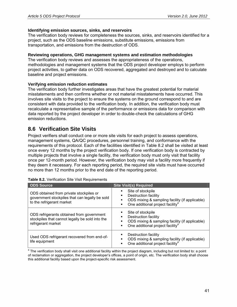
Article 5 ODS Project Protocol Version 2.0, June 2012
41
Identifying emission sources, sinks, and reservoirs The verification body reviews for completeness the sources, sinks, and reservoirs identified for a project, such as the ODS baseline emissions, substitute emissions, emissions from transportation, and emissions from the destruction of ODS. Reviewing operations, GHG management systems and estimation methodologies The verification body reviews and assesses the appropriateness of the operations, methodologies and management systems that the ODS project developer employs to perform project activities, to gather data on ODS recovered, aggregated and destroyed and to calculate baseline and project emissions. Verifying emission reduction estimates The verification body further investigates areas that have the greatest potential for material misstatements and then confirms whether or not material misstatements have occurred. This involves site visits to the project to ensure the systems on the ground correspond to and are consistent with data provided to the verification body. In addition, the verification body must recalculate a representative sample of the performance or emissions data for comparison with data reported by the project developer in order to double-check the calculations of GHG emission reductions.
8.6 Verification Site Visits Project verifiers shall conduct one or more site visits for each project to assess operations, management systems, QA/QC procedures, personnel training, and conformance with the requirements of this protocol. Each of the facilities identified in Table 8.2 shall be visited at least once every 12 months by the project verification body. If one verification body is contracted by multiple projects that involve a single facility, the verification body must only visit that facility once per 12-month period. However, the verification body may visit a facility more frequently if they deem it necessary. For each reporting period, the required site visits must have occurred no more than 12 months prior to the end date of the reporting period. Table 8.2. Verification Site Visit Requirements ODS Source Site Visit(s) Required
ODS obtained from private stockpiles or government stockpiles that can legally be sold to the refrigerant market
Site of stockpile Destruction facility ODS mixing & sampling facility (if applicable) One additional project facilitya
ODS refrigerants obtained from government stockpiles that cannot legally be sold into the refrigerant market
Site of stockpile Destruction facility ODS mixing & sampling facility (if applicable) One additional project facilitya
Used ODS refrigerant recovered from end-of-life equipment
Destruction facility ODS mixing & sampling facility (if applicable) One additional project facilitya
a The verification body shall visit one additional facility within the project diagram, including but not limited to: a point of reclamation or aggregation, the project developer’s offices, a point of origin, etc. The verification body shall choose this additional facility based upon the project-specific risk assessment.
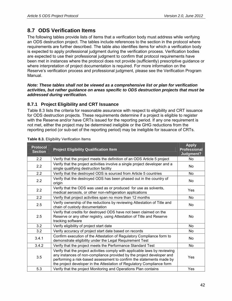
Article 5 ODS Project Protocol Version 2.0, June 2012
42
8.7 ODS Verification Items The following tables provide lists of items that a verification body must address while verifying an ODS destruction project. The tables include references to the section in the protocol where requirements are further described. The table also identifies items for which a verification body is expected to apply professional judgment during the verification process. Verification bodies are expected to use their professional judgment to confirm that protocol requirements have been met in instances where the protocol does not provide (sufficiently) prescriptive guidance or where interpretation of project documentation is required. For more information on the Reserve’s verification process and professional judgment, please see the Verification Program Manual. Note: These tables shall not be viewed as a comprehensive list or plan for verification activities, but rather guidance on areas specific to ODS destruction projects that must be addressed during verification.
8.7.1 Project Eligibility and CRT Issuance
Table 8.3 lists the criteria for reasonable assurance with respect to eligibility and CRT issuance for ODS destruction projects. These requirements determine if a project is eligible to register with the Reserve and/or have CRTs issued for the reporting period. If any one requirement is not met, either the project may be determined ineligible or the GHG reductions from the reporting period (or sub-set of the reporting period) may be ineligible for issuance of CRTs. Table 8.3. Eligibility Verification Items
Protocol Section
Project Eligibility Qualification Item Apply
Professional Judgment?
2.2 Verify that the project meets the definition of an ODS Article 5 project No
2.2 Verify that the project activities involve a single project developer and a single qualifying destruction facility No
2.2 Verify that the destroyed ODS is sourced from Article 5 countries No
2.2 Verify that the destroyed ODS has been phased out in the country of origin No
2.2 Verify that the ODS was used as or produced for use as solvents, medical aerosols, or other non-refrigeration applications Yes
2.2 Verify that project activities span no more than 12 months No
2.5 Verify ownership of the reductions by reviewing Attestation of Title and chain of custody documentation No
2.5 Verify that credits for destroyed ODS have not been claimed on the Reserve or any other registry, using Attestation of Title and Reserve tracking software
No
3.2 Verify eligibility of project start date No 3.2 Verify accuracy of project start date based on records No
3.4.1 Confirm execution of the Attestation of Regulatory Compliance form to demonstrate eligibility under the Legal Requirement Test No
3.4.2 Verify that the project meets the Performance Standard Test No
3.5
Verify that the project activities comply with applicable laws by reviewing any instances of non-compliance provided by the project developer and performing a risk-based assessment to confirm the statements made by the project developer in the Attestation of Regulatory Compliance form
Yes
5.3 Verify that the project Monitoring and Operations Plan contains Yes

Article 5 ODS Project Protocol Version 2.0, June 2012
43
Protocol Section
Project Eligibility Qualification Item Apply
Professional Judgment?
procedures for ascertaining and demonstrating that the project passes the Legal Requirement Test at all times
5.3 Verify that monitoring meets the requirements of the protocol; if it does not, verify that a variance has been approved for monitoring variations Yes
6 Verify the Monitoring and Operations Plan includes a project diagram and that the project diagram is complete, accurate, and up-to-date No
Appendix C
Verify that the destruction facility meets the requirements of this protocol; if the facility is not a RCRA-approved HWC, verify that it has been third-party certified as meeting the requirements of the TEAP Report on the Task Force on HCFC Issues in Appendix C and has successfully completed the comprehensive performance testing within the three years prior to the end date of destruction activities
No
If any variances were granted, verify that variance requirements were met and properly applied No
8.7.2 Conformance with Operational Requirements and ODS Eligibility
Table 8.4 lists the verification items to determine the project’s conformance with the operational and monitoring requirements of this protocol, and the eligibility of discreet ODS sources. A subset of destroyed ODS may be deemed ineligible if it was obtained in a manner inconsistent with this protocol, or if documentation is insufficient. If any items in Table 8.4 cannot be verified, no CRTs may be issued for that quantity of ODS. Table 8.4. Operational Requirement and ODS Eligibility Verification Items
Protocol Section
Operational Requirement and ODS Eligibility Items Apply
Professional Judgment?
5.3 Verify that the destruction facility monitored the parameters identified in Section 6 No
6.1 For all ODS, verify that information has been correctly entered in Reserve tracking system and that the Certificate of Destruction entry is unique to this project
No
6.2 For all ODS, verify that the point of origin is correctly identified and documented Yes
6.2, 6.4 For all ODS, verify that the point of origin documentation agrees with the data reported at the destruction facility (weight and composition) with no significant discrepancies
Yes
6.3 For all ODS, verify that the ODS can be tracked through retained chain of custody documentation from the Certificate of Destruction back to the point of origin
Yes
6.4 Verify that the scales used for measuring mass of ODS destroyed are properly maintained and tested for calibration quarterly No
6.4 Verify that the weight of full and empty ODS containers was measured two days prior to destruction commencing and two days following completion, respectively
No
6.4 Verify that all ODS samples were taken by a third-party technician while in the possession of the destruction company No
6.4 Verify the chain of custody by which ODS sample was transferred from the destruction facility to the lab No
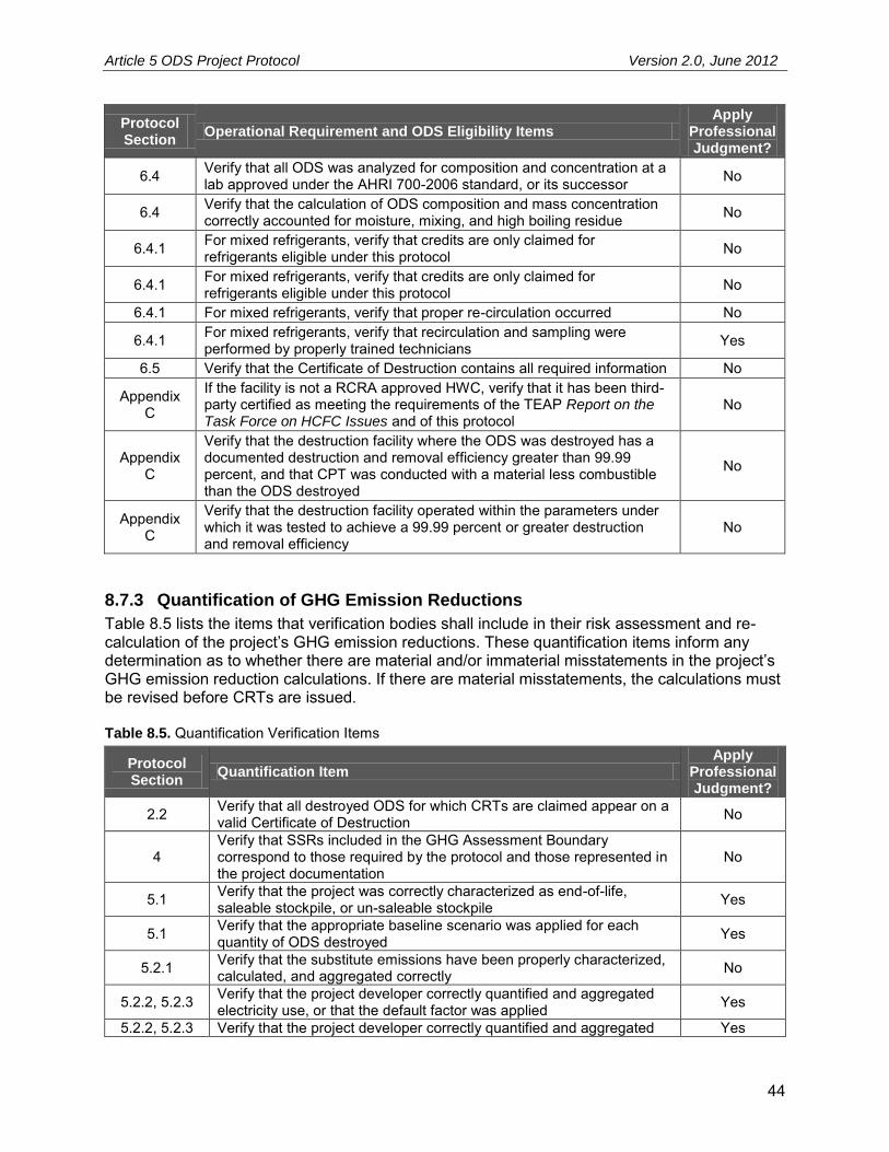
Article 5 ODS Project Protocol Version 2.0, June 2012
44
Protocol Section
Operational Requirement and ODS Eligibility Items Apply
Professional Judgment?
6.4 Verify that all ODS was analyzed for composition and concentration at a lab approved under the AHRI 700-2006 standard, or its successor No
6.4 Verify that the calculation of ODS composition and mass concentration correctly accounted for moisture, mixing, and high boiling residue No
6.4.1 For mixed refrigerants, verify that credits are only claimed for refrigerants eligible under this protocol No
6.4.1 For mixed refrigerants, verify that credits are only claimed for refrigerants eligible under this protocol No
6.4.1 For mixed refrigerants, verify that proper re-circulation occurred No
6.4.1 For mixed refrigerants, verify that recirculation and sampling were performed by properly trained technicians Yes
6.5 Verify that the Certificate of Destruction contains all required information No
Appendix C
If the facility is not a RCRA approved HWC, verify that it has been third-party certified as meeting the requirements of the TEAP Report on the Task Force on HCFC Issues and of this protocol
No
Appendix C
Verify that the destruction facility where the ODS was destroyed has a documented destruction and removal efficiency greater than 99.99 percent, and that CPT was conducted with a material less combustible than the ODS destroyed
No
Appendix C
Verify that the destruction facility operated within the parameters under which it was tested to achieve a 99.99 percent or greater destruction and removal efficiency
No
8.7.3 Quantification of GHG Emission Reductions
Table 8.5 lists the items that verification bodies shall include in their risk assessment and re-calculation of the project’s GHG emission reductions. These quantification items inform any determination as to whether there are material and/or immaterial misstatements in the project’s GHG emission reduction calculations. If there are material misstatements, the calculations must be revised before CRTs are issued. Table 8.5. Quantification Verification Items
Protocol Section
Quantification Item Apply
Professional Judgment?
2.2 Verify that all destroyed ODS for which CRTs are claimed appear on a valid Certificate of Destruction No
4 Verify that SSRs included in the GHG Assessment Boundary correspond to those required by the protocol and those represented in the project documentation
No
5.1 Verify that the project was correctly characterized as end-of-life, saleable stockpile, or un-saleable stockpile Yes
5.1 Verify that the appropriate baseline scenario was applied for each quantity of ODS destroyed Yes
5.2.1 Verify that the substitute emissions have been properly characterized, calculated, and aggregated correctly No
5.2.2, 5.2.3 Verify that the project developer correctly quantified and aggregated electricity use, or that the default factor was applied Yes
5.2.2, 5.2.3 Verify that the project developer correctly quantified and aggregated Yes
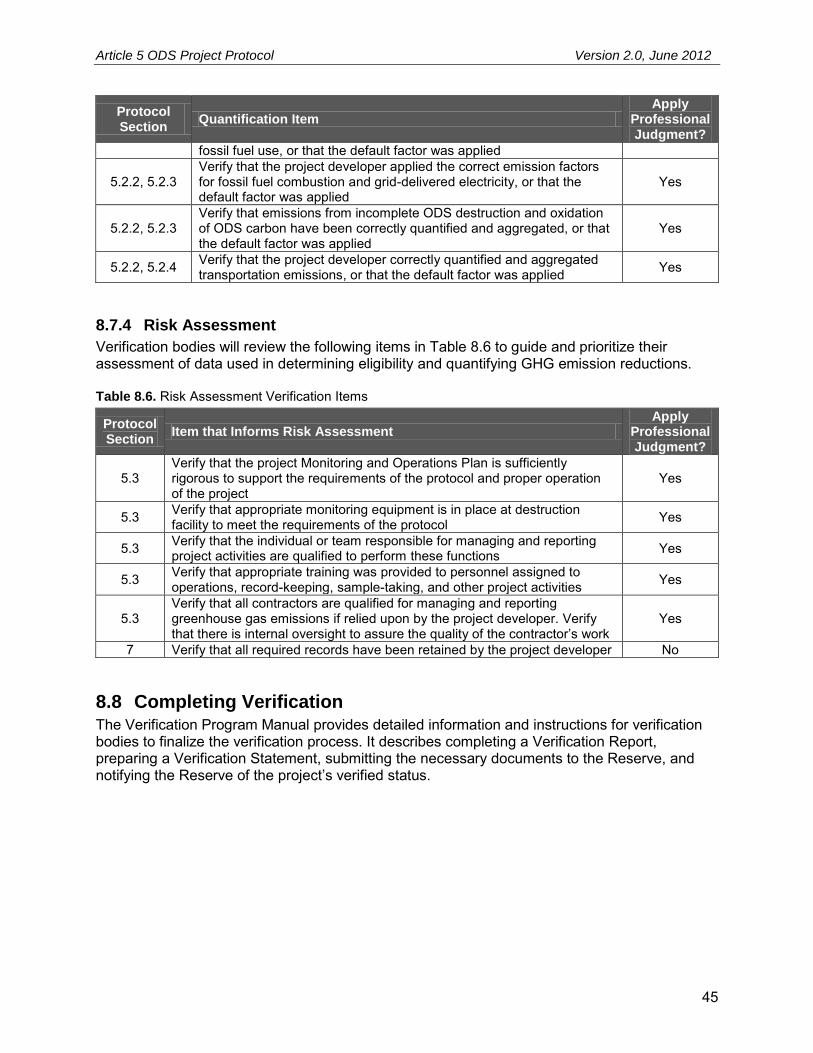
Article 5 ODS Project Protocol Version 2.0, June 2012
45
Protocol Section
Quantification Item Apply
Professional Judgment?
fossil fuel use, or that the default factor was applied
5.2.2, 5.2.3 Verify that the project developer applied the correct emission factors for fossil fuel combustion and grid-delivered electricity, or that the default factor was applied
Yes
5.2.2, 5.2.3 Verify that emissions from incomplete ODS destruction and oxidation of ODS carbon have been correctly quantified and aggregated, or that the default factor was applied
Yes
5.2.2, 5.2.4 Verify that the project developer correctly quantified and aggregated transportation emissions, or that the default factor was applied Yes
8.7.4 Risk Assessment
Verification bodies will review the following items in Table 8.6 to guide and prioritize their assessment of data used in determining eligibility and quantifying GHG emission reductions. Table 8.6. Risk Assessment Verification Items
Protocol Section
Item that Informs Risk Assessment Apply
Professional Judgment?
5.3 Verify that the project Monitoring and Operations Plan is sufficiently rigorous to support the requirements of the protocol and proper operation of the project
Yes
5.3 Verify that appropriate monitoring equipment is in place at destruction facility to meet the requirements of the protocol Yes
5.3 Verify that the individual or team responsible for managing and reporting project activities are qualified to perform these functions Yes
5.3 Verify that appropriate training was provided to personnel assigned to operations, record-keeping, sample-taking, and other project activities Yes
5.3 Verify that all contractors are qualified for managing and reporting greenhouse gas emissions if relied upon by the project developer. Verify that there is internal oversight to assure the quality of the contractor’s work
Yes
7 Verify that all required records have been retained by the project developer No
8.8 Completing Verification The Verification Program Manual provides detailed information and instructions for verification bodies to finalize the verification process. It describes completing a Verification Report, preparing a Verification Statement, submitting the necessary documents to the Reserve, and notifying the Reserve of the project’s verified status.

Article 5 ODS Project Protocol Version 2.0, June 2012
46
9 Glossary of Terms Certificate of Destruction An official document provided by the destruction facility
certifying the date, quantity, and type of ODS destroyed.
Commencement of destruction process
When the ODS waste-stream is hooked up to the destruction chamber.
Commercial refrigeration equipment
The refrigeration appliances used in the retail food, cold storage warehouse, or any other sector that require cold storage. Retail food includes the refrigeration equipment found in supermarkets, grocery and convenience stores, restaurants, and other food service establishments. Cold storage includes the refrigeration equipment used to house perishable goods or any manufactured product requiring refrigerated storage.
Container An air- and water-tight unit for storing and/or transporting ODS material without leakage or escape of ODS.
Destruction Destruction of ozone depleting substances by qualified destruction, transformation, or conversion plants achieving greater than 99.99 percent destruction and removal efficiency. Destruction may be performed using any technology, including transformation, that results in the complete breakdown of the ODS into either a waste or usable by-product.
Destruction facility A facility that destroys, transforms, or converts ozone depleting substances using a technology that meets the standards defined by the UN Environment Programme Technology and Economic Assessment Panel Task Force on Destruction Technologies.38
Emissions rate The annual rate at which ODS is lost to the atmosphere, including emissions from leaks during operation and servicing events.
Generator The facility from which the ODS material on a single Certificate of Destruction departed prior to receipt by the destruction facility. If the material on a single Certificate of Destruction was aggregated as multiple shipments to the destruction facility, then the destruction facility shall be the Generator.
Ozone depleting substances (ODS)
Ozone depleting substances are substances known to deplete the stratospheric ozone layer. The ODS controlled under the Montreal Protocol and its Amendments are chlorofluorocarbons (CFC), hydrochlorofluorocarbons (HCFC), halons, methyl bromide (CH3Br), carbon tetrachloride (CCl4), methyl chloroform (CH3CCl3), hydrobromofluorocarbons (HBFC) and bromochloromethane (CHBrCl). 39
Recharge Replenishment of refrigerant agent (using reclaimed or virgin
38
United Nations Environment Programme. (November 11, 2003). Report of the Fifteenth Meeting of the Parties to the Montreal Protocol on Substances that Deplete the Ozone Layer. OzL.Pro.15/9, Nairobi. 39
IPCC. Available at http://www.mnp.nl/ipcc/pages_media/SROC-final/SROC_A2.pdf.

Article 5 ODS Project Protocol Version 2.0, June 2012
47
material) into equipment that is below its full capacity because of leakage or because it has been evacuated for servicing or other maintenance.
Reclaim Reprocessing and upgrading of a recovered ozone depleting substance through mechanisms such as filtering, drying, distillation and chemical treatment in order to restore the ODS to a specified standard of performance. Chemical analysis is required to determine that appropriate product specifications are met. It often involves processing off-site at a central facility.
Recovery The removal of ozone depleting substances from machinery, equipment, containment vessels, etc., into an external container during servicing or prior to disposal without necessarily testing or processing it in any way.
Reuse/recycle Reuse of a recovered ozone depleting substance following a basic cleaning process such as filtering and drying. For refrigerants, recycling normally involves recharge back into equipment and it often occurs on-site.
Startup, shutdown, and malfunction plan
A plan, as specified under 40 CFR 63.1206, that includes a description of potential causes of malfunctions, including releases from emergency safety vents, that may result in significant releases of hazardous air pollutants, and actions the source is taking to minimize the frequency and severity of those malfunctions.
Stockpile ODS stored for future use or disposal in bulk quantities at a single location. These quantities may be composed of many small containers or a single large container.
Substitute refrigerant Those refrigerants that will be used to fulfill the function that would have been filled by the destroyed ODS refrigerants. These refrigerants may be drop-in replacements used in equipment that previously used the type of ODS destroyed, or may be used in new equipment that fulfills the same market function.
Substitute emissions A term used in this protocol to describe the greenhouse gases emitted from the use of substitute chemicals used to replace the ODS destroyed by a project.
Transportation system A term used to encompass the entirety of the system that moves the ODS from the country of origin to the destruction facility.

Article 5 ODS Project Protocol Version 2.0, June 2012
48
10 References Air-Conditioning, Heating, and Refrigeration Institute. (2006). Standard 700: 2006 Standard for Specifications for Fluorocarbon Refrigerants. ARGE Energy Changes Projektentwicklung GmbH, Tanzer Consulting Gmbh, & USG Umweltservice GmbH. (2008). Emission reductions due to controlled recovering of Chlorofluorocarbons (CFC) from end-of-life refrigerator and freezer appliances.
California Climate Action Registry. (2009). General Reporting Protocol, Version 3.1.
Climate Action Reserve. (October 26, 2011). Program Manual.
Climate Action Reserve. (December 20, 2010). Verification Program Manual.
EOS Climate. (2008). Methodology for Ozone Depleting Substances Destruction Projects.
HR 2454, American Clean Energy and Security Act of 2009.
ICF International. (2009). ODS Destruction in the United States of America and Abroad. U.S. Environmental Protection Agency, Stratospheric Protection Division.
International Organization for Standardization (ISO) 14064-2. (2006). Greenhouse Gases – Part 2: Specification with guidance at the project level for quantification, monitoring and reporting of greenhouse gas emission reductions or removal enhancements.
Lim, Sung Yong, Senior Manager, Fund Administration Department, Korea Specialty Chemical Industry Association. (2010). Personal correspondence.
National Institute of Standards and Technology. (2012). Specifications, Tolerance, and Other Technical Requirements for Weighing and Measuring Devices. NIST Handbook 44.
Ozone Secretariat. (2010). CFC Destruction in A5 Parties. personal communication.
Scheutz et al. (2007). Attenuation of fluorocarbons released from foam insulation in landfills. Environmental Science & Technology, 41: 7714-7722.
Scheutz et al. (2007). Release of fluorocarbons from insulation foam in home appliances during shredding. Journal of the Air & Waste Management Association, Technical Paper.
U.S. Clean Air Act. Title VI: Protection of Stratospheric Ozone. Section 604(a).
U.S. Code of Federal Regulations. Title 40—Protection of Environment, Chapter I—Environmental Protection Agency, Subchapter C—Air Programs, Part 82—Protection of the Stratospheric Ozone.
U.S. Environmental Protection Agency, Climate Leaders. (2007). Greenhouse Gas Inventory Protocol Core Module Guidance: Direct Emissions from Stationary Combustion Sources.
U.S. Environmental Protection Agency, Climate Leaders. (2008). Greenhouse Gas Inventory Protocol Core Module Guidance: Optional emissions from business travel, commuting, and product transport.
U.S. Environmental Protection Agency. (2008). Inventory of U.S. Greenhouse Gas Emissions and Sinks: 1990-2007.

Article 5 ODS Project Protocol Version 2.0, June 2012
49
U.S. Environmental Protection Agency. (December 2008). eGRID2007 Version 1.1, Year 2005 Greenhouse Gas Annual Output Emission Rates. Available at http://www.epa.gov/cleanenergy/energy-resources/egrid/index.html.
United Nations Environment Programme, Ozone Secretariat. (2009). Addendum to: Information provided by Parties in accordance with Article 7 of the Montreal Protocol on Substances that Deplete the Ozone Layer.
United Nations Environment Programme, Ozone Secretariat. (1987 and subsequent amendments). The Montreal Protocol on Substances that Deplete the Ozone Layer.
United Nations Environment Programme, Ozone Secretariat. Data Access Center. Retrieved on September 22, 2009, from http://ozone.unep.org/Data_Reporting/Data_Access/.
United Nations Environment Programme, Ozone Secretariat. Status of Ratification. Retrieved on September 24, 2009, from http://ozone.unep.org/Ratification_status/montreal_protocol.shtml
United Nations Environment Programme, Ozone Secretariat. List of Parties categorized as operating under Article 5 paragraph 1 of the Montreal Protocol. Retrieved on September 24, 2009, from http://ozone.unep.org/Ratification_status/list_of_article_5_parties.shtml
United Nations Environment Programme, Technology and Economic Assessment Panel. (2005). Report of the Task Force on Foam End-of-Life Issues.
United Nations Environment Programme, Technology and Economic Assessment Panel. (2005). Special report: Safeguarding the ozone layer and the global climate system: issues related to hydrofluorocarbons and perfluorocarbons.
United Nations Environment Programme, Technology and Economic Assessment Panel. (2006). Report of the Refrigeration, Air Conditioning and Heat Pumps Technical Options Committee.
United Nations Environment Programme, Technology and Economic Assessment Panel. (2006). Progress Report.
United Nations Environment Programme, Technology and Economic Assessment Panel. (2007). Report of the Task Force on HCFC Issues.
United Nations Environment Programme, Technology and Economic Assessment Panel. (2002). Report of the Task Force on Destruction Technologies.
World Meteorological Organization and United Nations Environment Programme, Intergovernmental Panel on Climate Change (IPCC). 2006 IPCC Guidelines for National Greenhouse Gas Inventories.
World Resources Institute and World Business Council for Sustainable Development. (2005). The Greenhouse Gas Protocol for Project Accounting.

Article 5 ODS Project Protocol Version 2.0, June 2012
50
Appendix A Summary of Legal Requirement Test Development
Management activities for ozone depleting substances are dictated in Article 5 countries by both the Montreal Protocol and domestic law. This appendix provides background information on the Montreal Protocol. Further, this section demonstrates that this framework does not require the destruction of ODS. Provided that there are no domestic rules requiring destruction of ODS in the source country, destruction of imported ODS from Article 5 countries meets the Legal Requirement Test under the Climate Action Reserve Article 5 Ozone Depleting Substances Project Protocol.
A.1 Montreal Protocol The original Montreal Protocol, signed in 1987, was the first step in international efforts to protect stratospheric ozone. Since that time, the Montreal Protocol has been repeatedly strengthened by both controlling additional ODS as well as by moving up the date by which previously controlled substances must be phased out. The Montreal Protocol controls only production and consumption (defined as production plus imports minus exports), but not emissions of ODS. There is no mandatory requirement to destroy ODS in the Montreal Protocol. Therefore, for analyses prepared under the Montreal Protocol, it is assumed that all ODS produced will eventually be released to the atmosphere, even though some developed countries have voluntary and/or mandatory requirements to destroy ODS. Under the original Montreal Protocol agreement (1987), non-Article 5 countries were required to begin phasing out CFC in 1993 and achieve a 50 percent reduction relative to 1986 consumption levels by 1998. Under this agreement, CFC were the only ODS addressed. The London Amendment (1990) changed the ODS emission schedule by requiring the complete phase-out of CFC, halons, and carbon tetrachloride by 2000 in developed countries, and by 2010 in developing countries. Methyl chloroform was also added to the list of controlled ODS, with phase-out in developed countries targeted in 2005, and in 2015 for developing countries. The Copenhagen Amendment (1992) significantly accelerated the phase-out of ODS and incorporated a HCFC phase-out for developed countries, beginning in 2004. Under this agreement, CFC, halons, carbon tetrachloride, methyl chloroform, and HBFC were targeted for complete phase-out in 1996 in developed countries. In addition, methyl bromide consumption was capped at 1991 levels. The Montreal Amendment (1997) included the phase-out of HCFC in developing countries, as well as the phase-out of methyl bromide in developed and developing countries in 2005 and 2015, respectively. The Beijing Amendment (1999) included tightened controls on the production and trade of HCFC. Bromochloromethane was also added to the list of controlled substances with phase-out targeted for 2002. At the 19th Meeting of the Parties in Montreal in September 2007, the Parties agreed to an adjustment that more aggressively phases out HCFC in both developed and developing countries. Developed countries must reduce HCFC production and consumption by 75 percent by 2010, 99.5 percent by 2020, and 100 percent by 2030. The 0.5 percent during the period 2020-2030 is restricted to the servicing of existing refrigeration and air-conditioning equipment

Article 5 ODS Project Protocol Version 2.0, June 2012
51
and is subject to review in 2015. Developing countries must freeze production and consumption of HCFC in 2013 and then reduce it by 10 percent in 2015, 35 percent by 2020, 67.5 percent by 2025, 97.5 percent by 2030 and 100 percent by 2040. The 2.5 percent during the period 2030-2039 is the average over that time frame (e.g. it can be five percent for five years and zero percent for the other five years), and is restricted to the servicing of existing refrigeration and air-conditioning equipment, subject to review in 2015. The result of Montreal Protocol with its amendments and adjustments is that as of January 1, 2010, CFC, halons, methyl chloroform, carbon tetrachloride, methyl bromide, and bromochloromethane will be phased out of production in both developed and developing countries. Therefore any ongoing uses of these substances must be supplied from already existing stocks that were never used, or from recycled or reclaimed material. However, it should be noted that there are allowances for some ongoing limited production of these substances for certain essential uses and critical uses approved by the Montreal Protocol Parties (e.g. as process agents and for quarantine and pre-shipment uses). Also, production and use of these substances as feedstock is not considered production since they are consumed in the feedstock process. Therefore, this protocol is limited to CFC used in refrigerant applications in Article 5 countries.

Article 5 ODS Project Protocol Version 2.0, June 2012
52
Appendix B Summary of Performance Standard Development
The Reserve assesses the additionality of projects through application of a Performance Standard Test and a Legal Requirement Test. The purpose of a performance standard is to establish a standard of performance applicable to all ODS projects that is significantly better than average ODS management practice, which, if met or exceeded by a project developer, satisfies one of the criterion of “additionality.”40 Appendix A described the regulatory framework surrounding the end-of-life treatment of refrigerant ODS and established that there is no international requirement to destroy ODS. However, the Reserve looks not only at what the regulatory requirements are, but also at the prevailing practice. Therefore, with the project defined as the destruction of ODS, the Reserve sought to establish whether destruction of ODS sourced in Article 5 countries is standard practice or whether it exceeds standard practice. 146 countries operate as parties under Article 5 of the Montreal Protocol.41 For this analysis, the Reserve assessed common practice for all ODS as well as the CFC phased out of production in these Article 5 countries by the Montreal Protocol and domestic law. Based on data collected by the United Nations Environment Programme (UNEP), the Reserve determined that destruction of CFC is not standard practice in any Article 5 country.
B.1 Methodology The primary data source for this analysis was the records maintained by the UNEP Ozone Secretariat.42 In a 2009 report, UNEP reported on ODS destruction from Article 5 countries between 1990 and 2008. This dataset indicated that, during this timeframe, only the following countries have reported destruction of ODS: Table B.1. Reported Destruction of ODS in Article 5 Countries43 Country Destruction 1990-2008 (tonnes)
Brazil 23.6 China 867.3 India 21 Mexico 0.7 Republic of Korea 3,078.7 South Africa 1 The former Yugoslav Republic of Macedonia 0.4
40 See the Climate Action Reserve’s Program Manual for further discussion of the Reserve’s general approach to determining additionality. 41 United Nations Environment Programme, Ozone Secretariat. List of Parties categorized as operating under Article 5 paragraph 1 of the Montreal Protocol. Retrieved on September 24, 2009, from http://ozone.unep.org/Ratification_status/list_of_article_5_parties.shtml. 42 United Nations Environment Programme, Ozone Secretariat. Data Access Center. Retrieved on September 22, 2009, from http://ozone.unep.org/Data_Reporting/Data_Access/. 43 UNEP. (2009) Addendum to Information provided by Parties in accordance with Article 7 of the Montreal Protocol on Substances that Deplete the Ozone Layer. Available at http://ozone.unep.org/Meeting_Documents/mop/21mop/MOP-21-5-Add-1E.pdf.
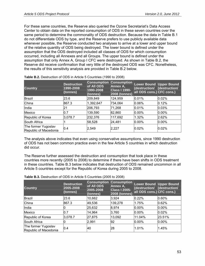
Article 5 ODS Project Protocol Version 2.0, June 2012
53
For these same countries, the Reserve also queried the Ozone Secretariat’s Data Access Center to obtain data on the reported consumption of ODS in these seven countries over the same period to determine the commonality of ODS destruction. Because the data in Table B.1 do not differentiate ODS by type, and the Reserve prefers to use publicly available data whenever possible, the Reserve conducted two analyses to arrive at a lower and upper bound of the relative quantity of ODS being destroyed. The lower bound is defined under the assumption that the ODS destroyed included all classes of ODS for which consumption occurred, including all Annexes and all Groups. The upper bound is defined under the assumption that only Annex A, Group I CFC were destroyed. As shown in Table B.2, the Reserve did receive confirmation that very little of the destroyed ODS was CFC. Nonetheless, the results of this sensitivity analysis are provided in Table B.2 below. Table B.2. Destruction of ODS in Article 5 Countries (1990 to 2008)
Country Destruction 1990-2008 (tonnes)
Consumption of All ODS 1990-2008 (tonnes)
Consumption Annex A, Class I 1990-2008 (tonnes)
Lower Bound (destruction/ all ODS cons.)
Upper Bound (destruction/ CFC cons.)
Brazil 23.6 209,849 124,959 0.01% 0.02% China 867.3 1,392,647 734,064 0.06% 0.12% India 21 206,793 71,268 0.01% 0.03% Mexico 0.7 139,590 82,860 0.00% 0.00% Republic of Korea 3,078.7 232,376 117,692 1.32% 2.62% South Africa 1 58,528 24,481 0.00% 0.00% The former Yugoslav Republic of Macedonia 0.4 2,549 2,227 0.02% 0.02%
The analysis above indicates that even using conservative assumptions, since 1990 destruction of ODS has not been common practice even in the few Article 5 countries in which destruction did occur. The Reserve further assessed the destruction and consumption that took place in these countries more recently (2005 to 2008) to determine if there have been shifts in ODS treatment in these countries. Table B.3 below indicates that destruction of ODS remained uncommon in all Article 5 countries except for the Republic of Korea during 2005 to 2008. Table B.3. Destruction of ODS in Article 5 Countries (2005 to 2008)
Country Destruction 2005-2008 (tonnes)
Consumption of All ODS 2005-2008 (tonnes)
Consumption Annex A, Class I 2005-2008 (tonnes)
Lower Bound (destruction/ all ODS cons.)
Upper Bound (destruction/ CFC cons.)
Brazil 23.6 10,662 3,924 0.22% 0.60% China 867.3 49,536 139,278 1.75% 0.62% India 0 25,632 8,974 0.00% 0.00% Mexico 0.7 14,964 3,760 0.00% 0.02% Republic of Korea 3,078.7 27,875 13,092 11.04% 23.51% South Africa 0 2,991 92 0.00% 0.00% The former Yugoslav Republic of Macedonia 0.4 40 28 1.01% 1.45%
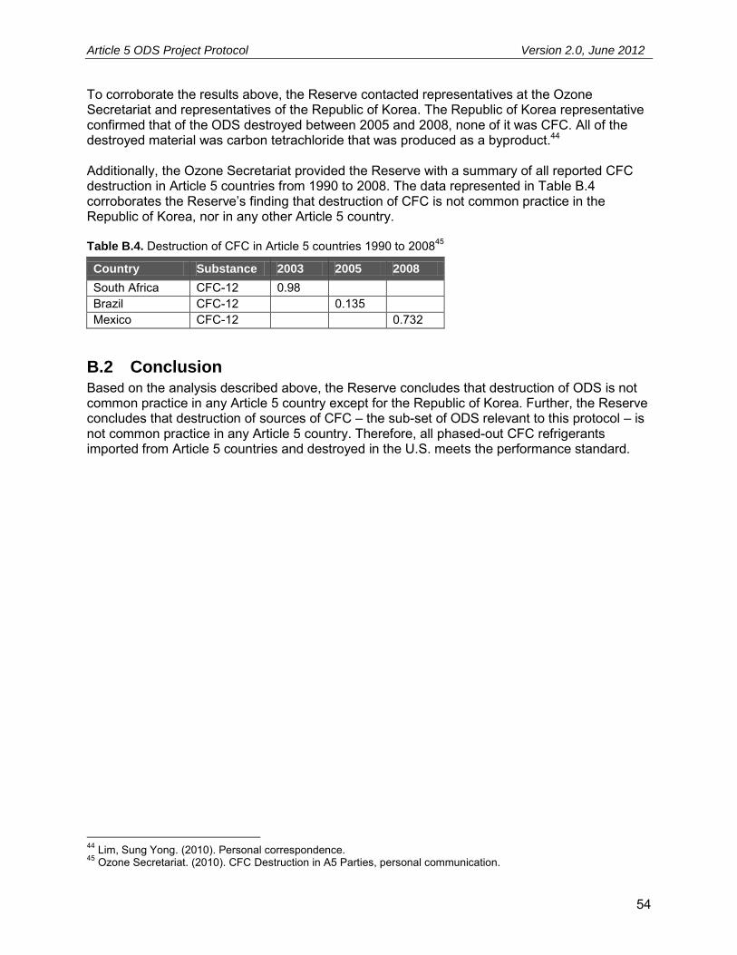
Article 5 ODS Project Protocol Version 2.0, June 2012
54
To corroborate the results above, the Reserve contacted representatives at the Ozone Secretariat and representatives of the Republic of Korea. The Republic of Korea representative confirmed that of the ODS destroyed between 2005 and 2008, none of it was CFC. All of the destroyed material was carbon tetrachloride that was produced as a byproduct.44 Additionally, the Ozone Secretariat provided the Reserve with a summary of all reported CFC destruction in Article 5 countries from 1990 to 2008. The data represented in Table B.4 corroborates the Reserve’s finding that destruction of CFC is not common practice in the Republic of Korea, nor in any other Article 5 country. Table B.4. Destruction of CFC in Article 5 countries 1990 to 200845
Country Substance 2003 2005 2008
South Africa CFC-12 0.98 Brazil CFC-12 0.135 Mexico CFC-12 0.732
B.2 Conclusion Based on the analysis described above, the Reserve concludes that destruction of ODS is not common practice in any Article 5 country except for the Republic of Korea. Further, the Reserve concludes that destruction of sources of CFC – the sub-set of ODS relevant to this protocol – is not common practice in any Article 5 country. Therefore, all phased-out CFC refrigerants imported from Article 5 countries and destroyed in the U.S. meets the performance standard.
44 Lim, Sung Yong. (2010). Personal correspondence. 45 Ozone Secretariat. (2010). CFC Destruction in A5 Parties, personal communication.

Article 5 ODS Project Protocol Version 2.0, June 2012
55
Appendix C EPA Rules Governing ODS Destruction This protocol requires that all ODS be destroyed at a destruction facility that is compliant with both the international standards specified in the TEAP Report of the Task Force on Destruction Technologies46 and Code of Good Housekeeping, as well as the requirements of domestic U.S. law. This appendix provides a brief summary of the rules dictated by domestic law for destruction of ODS, and the criteria that must be met for a destruction facility to qualify under this protocol. All ODS destruction is regulated under stratospheric ozone protection regulations under the Clean Air Act (CAA) (40 CFR 82). Additionally, because some ODS are classified as hazardous wastes (such as CFC-113, methyl chloroform, and carbon tetrachloride), facilities that handle these ODS are regulated under Resource Conservation and Recovery Act (RCRA). Hazardous waste combustors (HWCs, e.g. incinerators) that destroy ODS classified as hazardous waste are also regulated by the Maximum Achievable Control Technology (MACT) standard under the CAA. Under the authority of the CAA, the stratospheric ozone protection regulations (40 CFR Part 82, Subpart A) require that ODS be destroyed using one of the destruction technologies approved by the Montreal Protocol Parties which are:
1. Liquid injection incineration 2. Reactor cracking 3. Gaseous/fume oxidation 4. Rotary kiln incineration 5. Cement kiln 6. Radio frequency plasma 7. Municipal waste incinerators (only for the destruction of foams) 8. Argon arc plasma
Additionally, if the substance is to be considered “completely destroyed” as defined in the regulations, it must be destroyed to a 98 percent destruction efficiency (DE). This is slightly different from the Montreal Protocol Technology and Economic Assessment Panel (TEAP) destruction recommendations which include a destruction and removal efficiency (DRE) limit of 99.99 percent. DE is a more comprehensive measure of destruction than DRE as it includes emissions of undestroyed chemical from all points (e.g. stack gases, fly ash, scrubber, water, bottom ash), while DRE includes emissions of undestroyed chemical from the stack gas only. However, because of the relatively volatile nature of ODS and because, with the exception of foams, they are generally introduced as relatively clean fluids, one would not expect a very significant difference between DRE and DE. This protocol requires DRE of 99.99 percent for any destruction facility used under this protocol. Any destruction facility that is regulated by EPA as a RCRA-permitted HWC is considered a qualifying destruction facility under this protocol. Non-RCRA permitted facilities may also be deemed qualifying destruction facilities if they meet the pertinent guidelines provided by the TEAP Report of the Task Force on Destruction
46United Nations Environment Programme, Technology and Economic Assessment Panel. (2002). Report of the Task Force on Destruction Technologies.

Article 5 ODS Project Protocol Version 2.0, June 2012
56
Technologies, and reproduced below. By inclusion here, the recommendations of the excerpted section of the TEAP report shall be binding on all non-RCRA destruction facilities. Destruction facilities must provide third-party certified results indicating that the facility meets all performance criteria set forth below. Following the initial performance testing, project developers must demonstrate that the facility has conducted comprehensive performance testing at least every three years to validate compliance with the TEAP DRE and emissions limits as reproduced below. No ODS destruction credits shall be issued for destruction that occurs at a facility that has not passed the criteria below within three years of commencement of destruction activities. (Reproduced in full from TEAP Report of the Task Force on Destruction Technologies, Chapter 2, 2002. References in the following section pertain to the Report document, not this protocol.) CHAPTER 2 2.0 TECHNOLOGY SCREENING PROCESS 2.1 Criteria for Technology Screening The following screening criteria were developed by the UNEP TFDT. Technologies for use by the signatories to the Montreal Protocol to dispose of surplus inventories of ODS were assessed on the basis of:
1. Destruction and Removal Efficiency (DRE) 2. Emissions of dioxins/furans 3. Emissions of other pollutants (acid gases, particulate matter, and carbon monoxide) 4. Technical capability
The first three refer to technical performance criteria selected as measures of potential impacts of the technology on human health and the environment. The technical capability criterion indicates the extent to which the technology has been demonstrated to be able to dispose of ODS (or a comparable recalcitrant halogenated organic substance such as PCB) effectively and on a commercial scale. For convenience, the technical performance criteria are summarized in Table 2-1. These represent the minimum destruction and removal efficiencies and maximum emission of pollutants to the atmosphere permitted by technologies that qualify for consideration by the TFDT for recommendation to the Parties of the Montreal Protocol for approval as ODS destruction technologies. The technologies must also satisfy the criteria for technical capability as defined in Section 2.1.4. Table 2-1: Summary of Technical Performance Qualifications
47
Performance Qualification
Units Diluted Sources Concentrated Sources
DRE % 95 99.99 PCDDs/PCDFs ng-ITEQ/Nm3 0.5 0.2 HCl/Cl2 mg/Nm3 100 100 HF mg/Nm3 5 5
47 All concentrations of pollutants in stack gases and stack gas flow rates are expressed on the basis of dry gas at normal conditions of 0ºC and 101.3 kPa, and with the stack gas corrected to 11% O2.
Article 5 ODS Project Protocol Version 2.0, June 2012
57
HBr/Br2 mg/Nm3 5 5 Particulates (TSP) mg/Nm3 50 50 CO mg/Nm3 100 100
2.1.1 Destruction and Removal Efficiency
Destruction Efficiency (DE) 48 is a measure of how completely a particular technology destroys a contaminant of interest – in this case the transformation of ODS material into non-ODS by-products. There are two commonly used but different ways of measuring the extent of destruction – DE and Destruction and Removal Efficiency (DRE) .49 For a more detailed explanation of how DRE is calculated, see section 4.2.1. The terms are sometimes interchanged or used inappropriately. DE is a more comprehensive measure of destruction than DRE, because DE considers the amount of the chemical of interest that escapes destruction by being removed from the process in the stack gases and in all other residue streams. Most references citing performance of ODS destruction processes only provide data for stack emissions and thus, generally, data is only available for DRE and not DE. Because of the relatively volatile nature of ODS and because, with the exception of foams, they are generally introduced as relatively clean fluids, one would not expect a very significant difference between DRE and DE. For these reasons this update of ODS destruction technologies uses DRE as the measure of destruction efficiency. For the purposes of screening destruction technologies, the minimum acceptable DRE is:
95 percent for foams; and, 99.99 percent for concentrated sources.
It should be noted that measurements of the products of destruction of CFC, HCFC and halons in a plasma destruction process have indicated that interconversion of ODS can occur during the process. For example, under some conditions, the DRE of CFC-12 (CCl2F2) was measured as 99.9998 percent, but this was accompanied by a conversion of 25 percent of the input CFC-12 to CFC-13 (CClF3), which has the same ozone-depleting potential. The interconversion is less severe when hydrogen is present in the process, but can nonetheless be significant.50 For this reason, it is important to take into account all types of ODS in the stack gas in defining the DRE.
48 Destruction Efficiency (DE) is determined by subtracting from the mass of a chemical fed into a destruction system during a specific period of time the mass of that chemical that is released in stack gases, fly ash, scrubber water, bottom ash, and any other system residues and expressing that difference as a percentage of the mass of the chemical fed into the system. 49 Destruction and Removal Efficiency (DRE) has traditionally been determined by subtracting from the mass of a chemical fed into a destruction system during a specific period of time the mass of that chemical alone that is released in stack gases, and expressing that difference as a percentage of the mass of that chemical fed into the system. 50 Deam, R.T., Dayal, A.R., McAllister, T., Mundy, A.E., Western, R.J., Besley, L.M., Farmer, A.J.D., Horrigan, E.C., & Murphy, A.B. (1995). Interconversion of chlorofluorocarbons in plasmas. Journal of the Chemical Society, Chemical Communications, No.3, 347-348; Murphy, A.B., Farmer, A.J.D., Horrigan, E.C., & McAllister, T. (2002). Plasma destruction of ozone depleting substances. Plasma Chemistry and Plasma Processing, 22, 371-385.
Article 5 ODS Project Protocol Version 2.0, June 2012
58
For the reasons described in the previous paragraph, the Task Force recommends that future calculations of DRE use the approach described below.51
DRE of an ODS should be determined by subtracting from the number of moles of the ODS fed into a destruction system during a specific period of time, the total number of moles of all types of ODS that are released in stack gases, and expressing that difference as a percentage of the number of moles of the ODS fed into the system.
In mathematical terms, in
1
outin
1
DREN
NNi
i
Where N1
in is the number of moles of the ODS fed into the destruction system, and Niout is the
number of moles of the ith type of ODS that is released in the stack gases.
2.1.2 Emissions of Dioxins and Furans
Any high temperature process used to destroy ODS has associated with it the potential formation (as by-products) of polychlorinated dibenzo-paradioxins (PCDDs) and polychlorinated dibenzofurans (PCDFs). These substances are among the products of incomplete combustion (or PICs) of greatest concern for potential adverse effects on public health and the environment. The internationally recognized measure of the toxicity of these compounds is the toxic equivalency factor (ITEQ),52 which is a weighted measure of the toxicity for all the members of the families of these toxic compounds that are determined to be present. The task force members note that the World Health Organization has developed a new system for calculating TEQs, however, most of the existing data on emissions is expressed in the former ITEQ system established in 1988. For purposes of screening destruction technologies, the maximum concentration of dioxins and furans in the stack gas from destruction technologies is:
0.5 ng-ITEQ/Nm3 for foams; and, 0.2 ng-ITEQ/Nm3 for concentrated sources.
51 Since different ODS have different ozone depletion potentials (ODP), consideration should be given to taking into account the ODP of each type of ODS present in the stack gas in calculating the DRE. An appropriate definition that takes into account the differences in ODP is: DRE of an ODS is determined by subtracting from the number of moles of the ODS fed into a destruction system during a specific period of time, the total number of moles of all types of ODS that are released in stack gases, weighted by their ODP relative to that of the feed ODS, and expressing that difference as a percentage of the number of moles of the ODS fed into the system. 52 There are 75 chlorinated dibenzo-p-dioxins and 135 chlorinated dibenzofurans that share a similar chemical structure but that have a wide range in degree of chlorination and a corresponding wide range in toxicity. Of these, one specific dioxin [2,3,7,8-Tetrachlorodibenzo-p-dioxin, or (TCDD)] is the most toxic and best characterized of this family of compounds. Since PCDDs and PCDFs are generally released to the environment as mixtures of these compounds, the scientific community has developed a system of toxic equivalency factors (TEFs) which relate the biological potency of compounds in the dioxin/furan family to the reference TCDD compound. The concentration of each specific compound is multiplied by its corresponding TEF value, and the resulting potency-weighted concentration values are summed to form an expression of the mixture’s overall toxic equivalence (TEQ). The result of this exercise is a standardized expression of toxicity of a given mixture in terms of an equivalent amount of TCDD (the reference compound). The internationally accepted protocol for determining TEQ – i.e. ITEQ – was established by NATO in 1988. [North Atlantic Treaty Organization, Committee on the Challenge of Modern Society. (1988). Scientific Basis for the Development of International Toxicity Equivalency Factor (I-TEF), Method of Risk Assessment for Risk Assessment of Complex Mixtures of Dioxins and Related Compounds. Report No. 176, Washington, D.C.]
Article 5 ODS Project Protocol Version 2.0, June 2012
59
These criteria were determined to represent a reasonable compromise between more stringent standards already in place in some industrialized countries [for example, the Canada-Wide Standard of 0.08 ng/m3 (ITEQ)], and the situation in developing countries where standards may be less stringent or non-existent. Although a previous standard of 1.0 ng/m3 (ITEQ) had been suggested in the UNEP 1992 report, advances in technology in recent years, and the level of concern for emissions of these highly toxic substances justified a significantly more stringent level. 2.1.3 Emissions of Acid Gases, Particulate Matter and Carbon Monoxide Acid gases are generally formed when ODS are destroyed and these must be removed from the stack gases before the gases are released to the atmosphere. The following criteria for acid gases have been set for purposes of screening destruction technologies:
a maximum concentration in stack gases of 100 mg/Nm3 HCl/Cl2; a maximum concentration in stack gases of 5 mg/Nm3 HF; and, a maximum concentration in stack gases of 5 mg/Nm3 HBr/Br2.
Particulate matter is generally emitted in the stack gases of incinerators for a variety of reasons and can also be emitted in the stack gases of facilities using non-incineration technologies. For the purposes of screening technologies, the criterion for particulate matter is established as:
a maximum concentration of total suspended particulate (TSP) of 50 mg/Nm3. Carbon monoxide (CO) is generally released from incinerators resulting from incomplete combustion and may be released from some ODS destruction facilities because it is one form by which the carbon content of the ODS can exit the process. Carbon monoxide is a good measure of how well the destruction process is being controlled. For the purposes of screening technologies, the following criterion has been established:
a maximum CO concentration in the stack gas of 100 mg/Nm3. These maximum concentrations apply to both foams and concentrated sources. They were set to be achievable by a variety of available technologies while ensuring adequate protection of human health and the environment.
2.1.4 Technical Capability
As well as meeting the above performance requirements it is necessary that the destruction technologies have been demonstrated to be technically capable at an appropriate scale of operation. In practical terms, this means that the technology should be demonstrated to achieve the required DRE while satisfying the emissions criteria established above. Demonstration of destruction of ODS is preferred but not necessarily required. Destruction of halogenated compounds that are refractory, i.e. resistant to destruction, is acceptable. For example, demonstrated destruction of polychlorinated biphenyls (PCBs) was often accepted as an adequate surrogate for demonstrated ODS destruction. For this evaluation, an ODS destruction technology is considered technically capable if it meets the following minimum criteria:
Article 5 ODS Project Protocol Version 2.0, June 2012
60
It has been demonstrated to have destroyed ODS to the technical performance standards, on at least a pilot scale or demonstration scale (designated in Table 2-2 as “Yes”).
It has been demonstrated to have destroyed a refractory chlorinated organic compound other than an ODS, to the technical performance standards, on at least a pilot scale or demonstration scale (designated in Table 2-2 as “P,” which indicates that the technology is considered to have a high potential for application with ODS, but has not actually been demonstrated with ODS).
The processing capacity of an acceptable pilot plant or demonstration plant must be no less than 1.0 kg/hr of the substance to be destroyed, whether ODS or a suitable surrogate.
These criteria of technical capability will minimize the risk associated with technical performance and ensure that destruction of ODS will be performed in a predictable manner consistent with protecting the environment.

Article 5 ODS Project Protocol Version 2.0, June 2012
61
Appendix D Default Emissions Factors for Calculating ODS Transportation and Destruction Emissions
D.1 Summary The GHG Assessment Boundary for ODS destruction projects under the Reserve includes emissions in both the baseline and project scenario. These emission sources include the following: Baseline Project
Emissions of ODS from refrigerant applications
Emissions of substitute refrigerant applications
CO2 emissions from fossil fuel and electricity used in destruction facility
CO2 emissions from fossil fuel used in transport to destruction facility
ODS emissions from incomplete destruction of ODS CO2 emissions from ODS oxidation during
destruction All of these emission sources must be accounted for to ensure complete, accurate, and conservative calculations of project emission reductions. However, some of these emission sources are of a significantly greater magnitude than others, and some of the smaller sources are costly to track and verify, and difficult to assess. In order to lessen the burden on project developers and verifiers, the Reserve has calculated a standard deduction that can be applied to all projects to account for the following project scenario emissions:
1. CO2 emissions from fossil fuel and electricity used by the destruction facility 2. CO2 emissions from fossil fuel used for transporting the ODS to the destruction facility 3. ODS emissions from incomplete destruction of ODS 4. CO2 emissions from ODS oxidation during destruction
The aggregate of these emission sources amounts to less than 0.5 percent of total emission reductions under even the most conservative assumptions. As a result, a conservative emission factor can be applied. This appendix provides background on the development of these default emission factors.
D.2 Methodology and Analysis The Reserve created a model that incorporated all of the relevant equations from Section 5 to conservatively calculate emissions resulting from the four project sources mentioned above. The equations that have been rolled up into this emission factor are Equation 5.7 through Equation 5.12. In many cases, the equations used for estimating emissions required additional input and emission factors. Where calculations required such inputs (e.g. electricity grid emission factors), the most conservative factors available were used. Fossil fuel emissions from the destruction process were calculated based on confidential industry records made available to the Reserve that describe the energy requirements associated with ODS destruction projects. The assumptions used in this analysis are as follows:
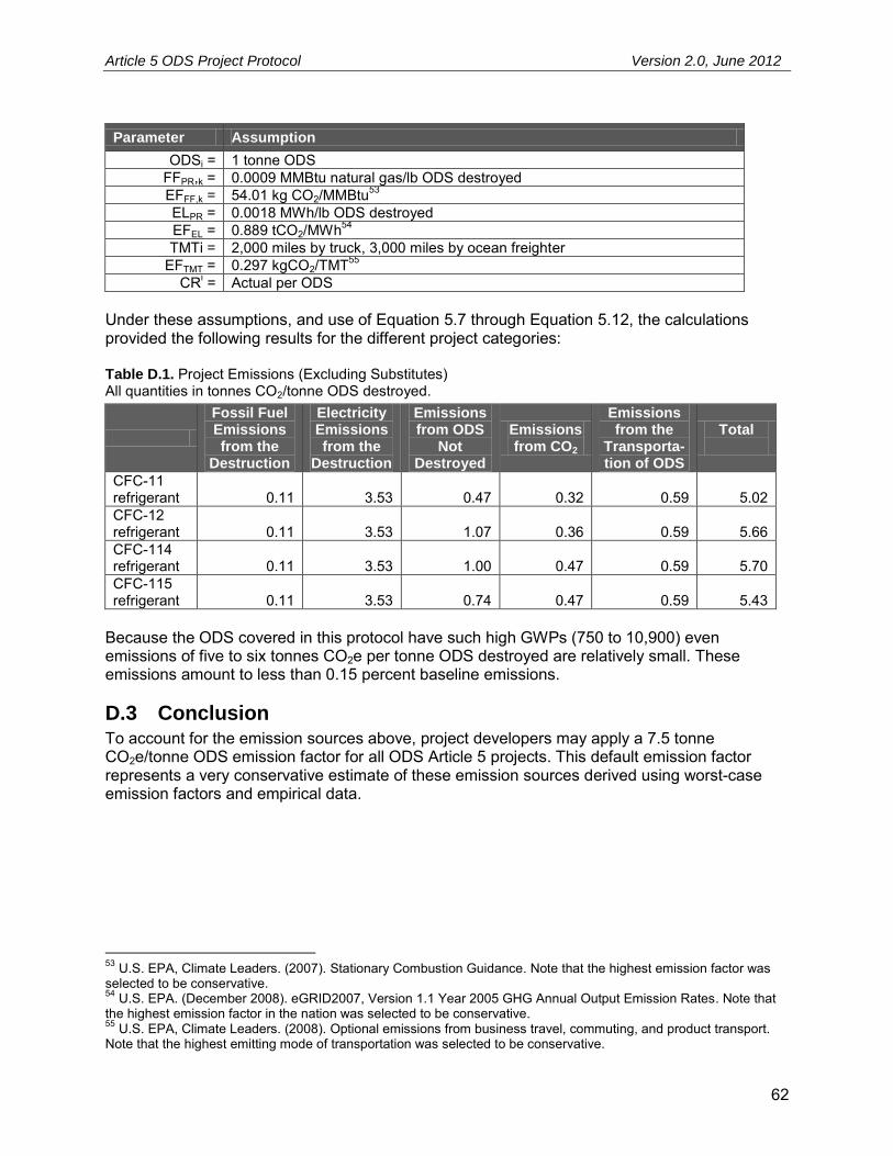
Article 5 ODS Project Protocol Version 2.0, June 2012
62
Parameter Assumption
ODSi = 1 tonne ODS FFPR,k = 0.0009 MMBtu natural gas/lb ODS destroyed EFFF,k = 54.01 kg CO2/MMBtu53 ELPR = 0.0018 MWh/lb ODS destroyed EFEL = 0.889 tCO2/MWh54 TMTi = 2,000 miles by truck, 3,000 miles by ocean freighter
EFTMT = 0.297 kgCO2/TMT55 CRi = Actual per ODS
Under these assumptions, and use of Equation 5.7 through Equation 5.12, the calculations provided the following results for the different project categories: Table D.1. Project Emissions (Excluding Substitutes) All quantities in tonnes CO2/tonne ODS destroyed.
Fossil Fuel Emissions from the
Destruction
Electricity Emissions from the
Destruction
Emissions from ODS
Not Destroyed
Emissions from CO2
Emissions from the
Transporta- tion of ODS
Total
CFC-11 refrigerant 0.11 3.53 0.47 0.32 0.59 5.02 CFC-12 refrigerant 0.11 3.53 1.07 0.36 0.59 5.66 CFC-114 refrigerant 0.11 3.53 1.00 0.47 0.59 5.70 CFC-115 refrigerant 0.11 3.53 0.74 0.47 0.59 5.43
Because the ODS covered in this protocol have such high GWPs (750 to 10,900) even emissions of five to six tonnes CO2e per tonne ODS destroyed are relatively small. These emissions amount to less than 0.15 percent baseline emissions.
D.3 Conclusion To account for the emission sources above, project developers may apply a 7.5 tonne CO2e/tonne ODS emission factor for all ODS Article 5 projects. This default emission factor represents a very conservative estimate of these emission sources derived using worst-case emission factors and empirical data.
53 U.S. EPA, Climate Leaders. (2007). Stationary Combustion Guidance. Note that the highest emission factor was selected to be conservative. 54 U.S. EPA. (December 2008). eGRID2007, Version 1.1 Year 2005 GHG Annual Output Emission Rates. Note that the highest emission factor in the nation was selected to be conservative. 55 U.S. EPA, Climate Leaders. (2008). Optional emissions from business travel, commuting, and product transport. Note that the highest emitting mode of transportation was selected to be conservative.
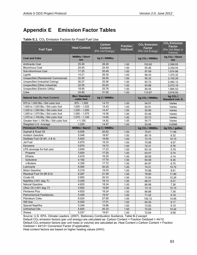
Article 5 ODS Project Protocol Version 2.0, June 2012
63
Appendix E Emission Factor Tables Table E.1. CO2 Emission Factors for Fossil Fuel Use
Fuel Type
Heat Content Carbon Content
(Per Unit Energy)
Fraction Oxidized
CO2 Emission Factor
(Per Unit Energy)
CO2 Emission Factor
(Per Unit Mass or Volume)
Coal and Coke MMBtu / Short
ton kg C / MMBtu kg CO2 / MMBtu
kg CO2 / Short ton
Anthracite Coal 25.09 28.26 1.00 103.62 2,599.83 Bituminous Coal 24.93 25.49 1.00 93.46 2,330.04 Sub-bituminous Coal 17.25 26.48 1.00 97.09 1,674.86 Lignite 14.21 26.30 1.00 96.43 1,370.32 Unspecified (Residential/ Commercial) 22.05 26.00 1.00 95.33 2,102.29 Unspecified (Industrial Coking) 26.27 25.56 1.00 93.72 2,462.12 Unspecified (Other Industrial) 22.05 25.63 1.00 93.98 2,072.19 Unspecified (Electric Utility) 19.95 25.76 1.00 94.45 1,884.53 Coke 24.80 31.00 1.00 113.67 2,818.93
Natural Gas (By Heat Content) Btu / Standard cubic foot
kg C / MMBtu kg CO2 / MMBtu kg CO2 /
Standard cub. ft.
975 to 1,000 Btu / Std cubic foot 975 – 1,000 14.73 1.00 54.01 Varies 1,000 to 1,025 Btu / Std cubic foot 1,000 – 1,025 14.43 1.00 52.91 Varies 1,025 to 1,050 Btu / Std cubic foot 1,025 – 1,050 14.47 1.00 53.06 Varies 1,050 to 1,075 Btu / Std cubic foot 1,050 – 1,075 14.58 1.00 53.46 Varies 1,075 to 1,100 Btu / Std cubic foot 1,075 – 1,100 14.65 1.00 53.72 Varies Greater than 1,100 Btu / Std cubic foot > 1,100 14.92 1.00 54.71 Varies Weighted U.S. Average 1,029 14.47 1.00 53.06 0.0546 Petroleum Products MMBtu / Barrel kg C / MMBtu kg CO2 / MMBtu kg CO2 / gallon
Asphalt & Road Oil 6.636 20.62 1.00 75.61 11.95 Aviation Gasoline 5.048 18.87 1.00 69.19 8.32 Distillate Fuel Oil (#1, 2 & 4) 5.825 19.95 1.00 73.15 10.15 Jet Fuel 5.670 19.33 1.00 70.88 9.57 Kerosene 5.670 19.72 1.00 72.31 9.76 LPG (average for fuel use) 3.849 17.23 1.00 63.16 5.79 Propane 3.824 17.20 1.00 63.07 5.74 Ethane 2.916 16.25 1.00 59.58 4.14 Isobutene 4.162 17.75 1.00 65.08 6.45 n-Butane 4.328 17.72 1.00 64.97 6.70 Lubricants 6.065 20.24 1.00 74.21 10.72 Motor Gasoline 5.218 19.33 1.00 70.88 8.81 Residual Fuel Oil (#5 & 6) 6.287 21.49 1.00 78.80 11.80 Crude Oil 5.800 20.33 1.00 74.54 10.29 Naphtha (<401 deg. F) 5.248 18.14 1.00 66.51 8.31 Natural Gasoline 4.620 18.24 1.00 66.88 7.36 Other Oil (>401 deg. F) 5.825 19.95 1.00 73.15 10.15 Pentanes Plus 4.620 18.24 1.00 66.88 7.36 Petrochemical Feedstocks 5.428 19.37 1.00 71.02 9.18 Petroleum Coke 6.024 27.85 1.00 102.12 14.65 Still Gas 6.000 17.51 1.00 64.20 9.17 Special Naphtha 5.248 19.86 1.00 72.82 9.10 Unfinished Oils 5.825 20.33 1.00 74.54 10.34 Waxes 5.537 19.81 1.00 72.64 9.58 Source: U.S. EPA, Climate Leaders. (2007). Stationary Combustion Guidance, Table B-2 except: Default CO2 emission factors (per unit energy) are calculated as: Carbon Content × Fraction Oxidized × 44/12. Default CO2 emission factors (per unit mass or volume) are calculated as: Heat Content x Carbon Content × Fraction Oxidized × 44/12× Conversion Factor (if applicable). Heat content factors are based on higher heating values (HHV).
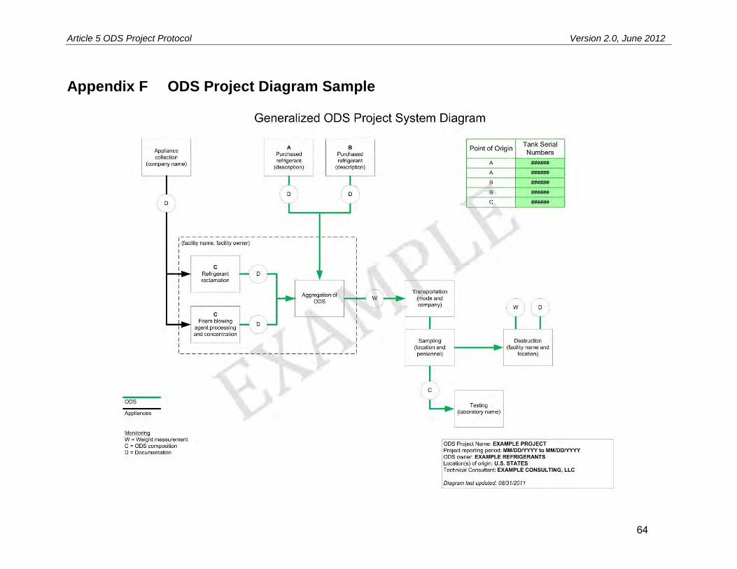
Article 5 ODS Project Protocol Version 2.0, June 2012
64
Appendix F ODS Project Diagram Sample
Please ensure that you are using the latest version of this document
U.S. Ozone Depleting Substances Project Protocol Version 2.0
ERRATA AND CLARIFICATIONS The Climate Action Reserve (Reserve) published its U.S. Ozone Depleting Substances Project Protocol Version 2.0 (U.S. ODS V2.0) in June 2012. While the Reserve intends for the U.S. ODS V2.0 to be a complete, transparent document, it recognizes that correction of errors and clarifications will be necessary as the protocol is implemented and issues are identified. This document is an official record of all errata and clarifications applicable to the U.S. ODS V2.0.1 Per the Reserve’s Program Manual, both errata and clarifications are considered effective on the date they are first posted on the Reserve website. The effective date of each erratum or clarification is clearly designated below. All listed and registered U.S. ODS projects must incorporate and adhere to these errata and clarifications when they undergo verification. The Reserve will incorporate both errata and clarifications into future versions of the U.S. ODS Project Protocol. All project developers and verification bodies must refer to this document to ensure that the most current guidance is adhered to in project design and verification. Verification bodies shall refer to this document immediately prior to uploading any Verification Statement to assure all issues are properly addressed and incorporated into verification activities. If you have any questions about the updates or clarifications in this document, please contact Policy at [email protected] or (213) 891-1444 x3.
1 See Section 4.3.4 of the Climate Action Reserve Program Manual for an explanation of the Reserve’s policies on
protocol errata and clarifications. “Errata” are issued to correct typographical errors. “Clarifications” are issued to ensure consistent interpretation and application of the protocol. For document management and program implementation purposes, both errata and clarifications to the U.S. ODS protocol are contained in this single document.

U.S. Ozone Depleting Substances Project Protocol Version 2.0 July 16, 2015 Errata and Clarifications
Please ensure that you are using the latest version of this document 1
Errata and Clarifications (arranged by protocol section)
Section 5
1. Accounting for Non-ODS Material (CLARIFICATION – January 29, 2013) ...................................... 2
2. Performance Requirements for Destruction Facilities (ERRATUM – July 16, 2015) ........................ 2
Section 6
3. Determining the Mass of ODS Destroyed (CLARIFICATION – April 11, 2013) ............................... 3

U.S. Ozone Depleting Substances Project Protocol Version 2.0 July 16, 2015 Errata and Clarifications
Please ensure that you are using the latest version of this document 2
Section 5
1. Accounting for Non-ODS Material (CLARIFICATION – January 29, 2013) Section: 5.1.1 (Calculating Baseline Emissions from Refrigerant Recovery and Resale) Context: The protocol states that projects shall only include the weight of pure ODS when calculating emission reductions. There are additional specific adjustments that were not mentioned in the protocol and it may not be clear how these adjustments should be made. Specifically, project developers shall exclude the weight of high boiling residue (HBR) in their calculation of emission reductions. Clarification: The definition of the term “Qrefr,i” in Equation 5.3 on page 21 shall read “Total quantity of pure refrigerant ODS i sent for destruction by the project.” The total weight of material destroyed by the project shall be adjusted to exclude the weight of ineligible material, including high boiling residue, as determined by the laboratory analysis required in Section 6.6 (in the case of multiple laboratory analyses, the highest reported value for HBR shall be used). In any case where the composition of the single ODS species is less than 100%, the value of this term must be adjusted to reflect the weight of pure ODS for each eligible chemical. For example, if a project destroys 1,000 lbs. of material that contains 5% high boiling residue and 95% eligible ODS i, the value of Qrefr,i would be 902.5 lbs. While water is also considered ineligible material, the moisture content requirement in Section 6.6 of the protocol (i.e. that the moisture content must be less than 75% of the saturation point for the ODS) already ensures that the weight of any moisture present will not have a material impact on the quantification of emission reductions. Thus the weight does not need to be adjusted to reflect the weight of moisture present in the sample.
2. Performance Requirements for Destruction Facilities (ERRATUM – July 16, 2015) Section: 5.2.4 (Calculating Site-Specific Project Emissions from ODS Destruction) Context: The protocol states that destruction “facilities are required to demonstrate their ability to achieve destruction efficiencies upwards of 99.99 percent for substances with thermal stability ratings higher than the ODS included under this protocol” (emphasis added). The reference cited for this statement explains a ranking system for the incinerability of ODS species based on their thermal stability. In this system, ODS species that are more thermally stable are more difficult to destroy. This results in a lower ranking. Thus, the lowest ranking (1) indicates the chemical that is most difficult to destroy, while the highest ranking (320) indicates the chemical that is easiest to destroy. The above-quoted statement in the U.S. ODS Project Protocol includes an error that communicates the opposite of the intended meaning of the statement. Correction: The second sentence in the first paragraph of this section shall read:

U.S. Ozone Depleting Substances Project Protocol Version 2.0 July 16, 2015 Errata and Clarifications
Please ensure that you are using the latest version of this document 3
“These facilities are required to demonstrate their ability to achieve destruction efficiencies upwards of 99.99 percent for substances with thermal stability rankings lower than the ODS included under this protocol.”
Section 6
3. Determining the Mass of ODS Destroyed (CLARIFICATION – April 11, 2013) Section: 6.6 (Concentrated ODS Composition and Quantity Analysis Requirements) Context: The protocol requires that the mass of ODS destroyed by the project be determined using (1) the difference between the measured weight of each container when it is full prior to destruction and the measured weight after it has been emptied and (2) the composition and concentration of material destroyed as determined by laboratory analyses of samples from each container. Clarification: The mass of ODS and any contaminants destroyed shall be considered equal to the difference between the full and empty weights of the containers, as measured by the scale at the destruction facility and recorded by the destruction facility on the weight tickets and the Certificate of Destruction. No adjustments shall be made by the project developer to the weights as measured and recorded by the destruction facility in calculating the mass of ODS and contaminants. Verifiers shall confirm that the weights recorded on the weight tickets and the Certificate of Destruction by the destruction facility are used without adjustment to calculate emission reductions. The mass of eligible ODS shall then be determined using these weights and the results of the laboratory analyses.