Embed Size (px)
Citation preview

Wireless Personal Communications 23: 321–352, 2002.© 2002 Kluwer Academic Publishers. Printed in the Netherlands.
Capacity of Wireless Communication SystemsEmploying Antenna Arrays, a Tutorial Study
MOHAMMAD ALI KHALIGHI, KOSAI RAOOF and GENEVIÈVE JOURDAINLaboratoire des Images et des Signaux (LIS), ENSIEG, Domaine Universitaire, BP-46,Saint Martin d’Hères, FranceE-mail: [email protected]
Abstract. A tutorial study is performed on the capacity of multiple antenna wireless communication systems.Multiple antenna structures can be classified into single-input multiple-outputs (SIMO), multiple-inputs single-output (MISO), and multiple-inputs multiple-outputs (MIMO) systems. Assuming that the channel is known atreceiver, capacity expressions are provided for each structure, under the conditions of quasi-static flat fading.Also, information rate limits are provided in each case for some suboptimal structures or detection techniques thatmay be used in practice. Using simulations for the case of flat Rayleigh fading, capacities of optimal/suboptimalimplementations are contrasted for each multi-antenna structure. Discussions are made on system design, regard-ing implementation complexity and practical limitations on achieving these capacities. In particular, the problemof fading correlation and required antenna spacing, effect of fast channel fading, and lack of channel knowledgeat receiver are discussed. Providing the results of the most recent researches considering the capacity of multi-antenna systems, as well as some new results, this paper can give a good perspective for designing appropriatearchitectures in different wireless communication applications.
Keywords: antenna arrays, channel capacity, information rates, wireless channels, multipath propagation, channelfading, spatial diversity, MIMO systems.
1. Introduction
Application of antenna arrays in wireless communication has been of special interest, par-ticularly in the last two decades. It has been shown by many studies that when an array isappropriately employed in a communication system, it helps in improving the system per-formance by increasing channel capacity and spectrum efficiency, extending range coverage,tailoring beam shape, steering multiple beams to track many subscribers, and compensat-ing antenna aperture distortion electronically. It also reduces multipath fading, cochannelinterferences (CCI), and bit error rate (BER) [1–3].
The antenna array may be used together with other methods such as channel coding,adaptive equalization, and interference cancelling to enhance the system performance.
A particular and important attraction of the use of antenna arrays is in high data ratewireless communication, such as transmission of high quality video information. A primarysolution to this high data rate requirement may be the increase in bandwidth (BW) or thetransmit power. However, these solutions are neither cost efficient nor satisfactory in practice.
An interesting alternative for increasing the channel capacity is to take use of multipathwireless channels, which has been of special interest in the past few years.
Since multipath propagation causes time-frequency signal fading, it is conventionally re-garded as an impediment to reliable communication [4]. However, it has been recently knownthat multipath propagation can multiply the attaining information rate in a wireless commu-

322 Mohammad Ali Khalighi et al.
nication system, provided that multiple antennas are used at both transmitter and receiver [5].If multipath scattering is sufficiently rich and properly exploited, use of multiple antennasat both sides of the radio link can result in enormous channel capacities. Pioneer works onthis type of systems have been performed in Bell Labs under a project named BLAST (BellLaboratories Layered Space Time architecture) [6].
Multiple antenna structures can be divided into three groups: use of antenna array only atreceiver, known as single-input multiple-outputs (SIMO) systems; use of antenna array onlyat transmitter, known as multiple-inputs single-output (MISO) systems; and use of antennaarrays at both transmitter and receiver, known as multiple-inputs multiple-outputs (MIMO)systems.
In this paper, our aim is to investigate how these different multi-antenna structures in-fluence the channel capacity. We will concentrate on point-to-point (single-user) wirelesscommunication systems all over the paper, except a brief discussion on multiuser systemsmade at the end of the paper. We try to present the most recent results of researches concerningthe capacity of multi-antenna wireless systems. Meanwhile, some new concepts are discussedand some interesting techniques are studied more precisely. In particular, information ratelimits of different multiple antenna structures are contrasted for different number of antennas;and complexity of various structures are discussed too. This can give to system designer aperspective to choose its preferred multi-antenna structure.
The reference list provided here is by no means complete, especially for the case of multi-user systems. However, it is tried to give a start point to the readers who want to follow somespecial subjects of interest. We have tried to present the most important and recent worksrelated to the topics treated in this paper.
After defining a channel model and explaining some assumptions regarding the channel inSection 2, capacity expressions will be presented in Section 3 for the general case of MIMOsystems. Next in Sections 4, 5, and 6, we will study particularly each one of SIMO, MISO,and MIMO systems, respectively. In each case, in addition to optimal structures and capacitybounds, some suboptimal implementations are also introduced, and information rate boundsare given. Also, the capacity of different implementations are contrasted with the single-inputsingle-output (SISO) channel case. In Section 7, a comparison is made between capacitiesof SIMO, MISO, and MIMO systems. In Section 8, some practical concepts concerning theimplementation of multi-antenna structures, as well as the effect of violation of each assump-tion made on the channel, will be discussed. At last, for the sake of completeness, a briefdiscussion is made in Section 9 on the implication of antenna arrays in multiuser systems.
2. Channel Model and Assumptions
The global scheme of a communication link is shown in Figure 1. The communication chan-nel includes the effect of transmit/receive antennas and the propagation medium. Far fieldconditions are assumed, that is, dominant reflectors are assumed to be sufficiently far from thetransmitter and the receiver. Under these conditions, angles of departure, angles of arrival andtime delays can be assumed almost the same over the extent of arrays’ apertures.
We will neglect the effect of antenna patterns and will assume that for both transmit andreceive arrays, antenna gains are the same for all elements over all propagation paths (an-tenna sidelobes are neglected). This is well justified together with the far field assumption. In

Capacity of Wireless Communication Systems Employing Antenna Arrays 323
Figure 1. Global scheme of MIMO communication structure.
this way, the overall antenna power gain will be considered the same for all transmit/receiveantenna pairs and will be denoted as gT R.
2.1. CHANNEL MODEL
A discrete time baseband channel model is considered. Considering a sampled model withone sample per symbol period, we will have a sufficient statistic for each transmitted/receivedsymbol, provided that the pulse shaping satisfies the Nyquist criterion [7]. Also, flat channelmodel is considered. So, the channel can be represented by a channel matrix H of dimensionMR × MT , with MR and MT the number of antenna elements at receiver and transmitter,respectively. Entries of H , hij , which are normalized1 proper2 complex random processes,represent the equivalent channel impulse response between j th transmit and ith receiveantennas. Antenna gains and propagation loss are excluded from hij .
Let x be the vector of transmitted symbols on MT antennas at one sample time. The vectorof corresponding received symbols on the receiver array, z, will be
z = aHx + n = y + n , (1)
where n is the vector of receiver noise whose elements are considered as (proper complex)zero-mean additive white Gaussian noise (AWGN) samples, with power of σ 2. a is a constantthat incorporates the effect of antenna gains and propagation loss,
a2 = α gTR (2)
with α the propagation power loss. Both α and gTR are assumed to be the same for alltransmit/receive antenna pairs, and to be constant over the signal BW.
2.2. CHANNEL FADING
The statistics of hij depends on the fading conditions. Unless otherwise mentioned, we willalways consider Rayleigh fading, which is valid for a rich scattering propagation environment,where no line-of-sight (LOS) exists between transmitter and receiver (denoted hereafter by Txand Rx, respectively) [4]. Under such conditions, hij will be proper complex Gaussian randomprocesses.
We suppose that the channel fading is not too rapid, so that H can be considered as constantduring one or more bursts.3 So, considering quasi-static conditions, the continuous channel
1 In the sense that E{hij h∗ij } = 1, with (.)∗ the complex conjugate operator
2 For proper (circularly-symmetric) complex random processes, the real and imaginary parts of the system canbe treated as two mutually orthogonal systems with the same dimensionality [8].
3 Bursts are assumed to be long enough, so that the definition of capacity for a given H matrix is meaningful.

324 Mohammad Ali Khalighi et al.
fading process is approximated as piece-wise constant. We define the coherence interval ofthe channel � (without dimension), as the number of symbol periods during which the prop-agation coefficients are almost constant; and they change to new independent values from aninterval to another [9]. With quasi-static model, in fact we assume that � → ∞. In this way,we may speak of random variables instead of random processes for hij .
We also assume that the antenna elements at both Tx and Rx are spaced sufficiently apart,so that independent fading can be considered for each Tx/Rx antenna pair. In other words, hijare assumed to be independent.
2.3. DEFINITION OF CAPACITY
For a deterministic channel (constant hij ), the channel capacity is also a deterministic valuewhich gives an upper bound on the information rate for reliable communication, as states theShannon theorem [10]. In other words, capacity is the maximum attainable mutual informationbetween the channel input-output. It is also the case when channel is not deterministic, buteach use of channel employs an independent realization of the H matrix [11, 12].
For the case of a randomly time-varying channel, the definition of the capacity dependson the bursts duration (codeword length) T . Here, the capacity is a random variable whoseinstant value depends on the corresponding H matrix. If T �, channel is said to behaveergodically,4 and an ergodic (statistical average) capacity Cav is defined [13–15], which againmeans the maximum attainable mutual information. If T �, as is our case (see the previousparagraph), the maximum mutual information is not equal to the channel capacity, and theShannon capacity of the channel may be even zero [12]. If we choose a transmission ratefor communication, there is a non-zero probability that the realization H is incapable ofsupporting it. When the instant capacity is less than the preassumed value, a channel outage issaid to be occurred. The mutual information can be regarded as a random quantity, giving riseto capacity-versus-outage considerations. The outage probability Pout is a useful parameter instudying channel capacity. Here, a tradeoff should be made between the expected throughputand outage [13, 14]. Note that in the literature, the capacity for a given outage probability issometimes called outage capacity, however, it is not a correct terminology!
In contrast to capacity-versus-outage, a delay-limited capacity CDL may be defined inthe case of T �, which corresponds to zero-outage capacity. CDL is zero for a SISOchannel without power control; it can be a positive value using optimal power control and/orby exploiting time/space diversity [13–15]. In the limit of infinite time/space diversity, CDL
equals the ergodic capacity Cav [14].In this paper, we will always consider capacity-versus-outage with Pout = 0.01, unless
otherwise mentioned. The corresponding capacity values correspond to 99% percentage pointof CCDF (Complementary Cumulative Distribution Function) of capacity.
It should be insisted that capacity is a limit to error-free bit rate that is provided by infor-mation theory. Any working system can only achieve a bit rate (at some desired small BER)that is only a fraction of capacity. With a given day’s technology, the challenge is to designefficient coding/decoding algorithms which can approach the information theory bound onbit rate. In what will be seen throughout this paper, the term “capacity” will also be used toindicate the maximum deliverable bit rate when using some special (suboptimal) structures ordetection techniques.
4 This is the case, for example, for some submarine acoustics and avionic channels.

Capacity of Wireless Communication Systems Employing Antenna Arrays 325
3. Capacity Expressions
It is assumed that the channel is estimated and tracked at Rx.5 The expressions that arepresented here, are valid under the assumption of perfect channel knowledge at Rx. Thediscussion on this assumption is made in Subsection 8.2.
We will consider the general MIMO system and will present the capacity expressions forthis general case. The capacity of SIMO and MISO systems and other degenerate cases can beeasily obtained using these general expressions, as it will be seen in next sections. We considerthe constraint that the total transmit power at each sample time is equal to PT .
3.1. UNKNOWN-CSI CAPACITY
If the channel state information (CSI) is not known at Tx, we distribute the available poweruniformly over the transmit antennas. In this case, the average received signal-to-noise ratiocorresponding to each transmit antenna at the receiver array, ρ, is
ρ = PT a2
MT σ 2= ρT
MT
(3)
with ρT the total average SNR at the receiver array. In this paper, with SNR we mean ρT .Regarding the far field conditions, ρ is considered the same for all Tx antennas. As it is shownin the appendix, the capacity is given by
C =M∑i=1
log2(1 + ρ λ2H,i) bps/Hz , (4)
where λH,i are the singular values of H and M = min(MT ,MR). Similar expressions areobtained in [12, 24]. Notice that for this expression to hold, the inputs on MT antennas mustbe statistically independent as it is shown in the appendix. Equation (4) can be interpretedas follows: in the case of flat fading, the MIMO channel can be reduced to a set of parallelindependent SISO subchannels, or to a set of independent orthogonal modes of excitation[18], for which the capacity can be easily calculated. The number of these parallel channelsequals the rank of H , and the gain of the ith equivalent parallel channel is equal to the λ2
H,i .Similar statements are given in [12, 19–21].
Equation (4) can be simplified as follows.
C = log2
M∏i
(1 + ρ λ2H,i) = log2 det[IMR
+ ρ �H�†H ]
= log2 det
[IMR
+ ρT
MT
HH †
]bps/Hz
(5)
which is the expression presented in [5] for a flat fading MIMO channel. As defined before,ρT = ρ MT . IMR
is the identity matrix with the dimension of (MR × MR).
5 See [16] for discussions on a completely unknown channel.

326 Mohammad Ali Khalighi et al.
3.2. KNOWN-CSI CAPACITY
If the CSI is provided at the transmitter, we can optimally distribute the total available powerPT on MT transmit antennas, a solution that is usually referred to as water filling (WF).6 Weassume that the CSI is provided for Tx in a causal manner, and no prediction can be madeon it (see [15] for the opposite case). We also assume that the CSI is delivered to Tx with nodelay.7
As it is shown in the appendix, the capacity in this case is given by
C =M∑i=1
log2
(1 + a2
σ 2λX,i λ
2H,i
)bps/Hz (6)
λX,i =(ψ − σ 2
a2 λ2H,i
)+, (7)
where,
(s)+ ={s, if s > 00, if s ≤ 0
. (8)
Similar expressions are obtained in [12, 24]. λX,i are the eigenvalues of the transmit-symbolsautocorrelation matrix, RX. ψ is determined so as to satisfy the constraint on the total transmitpower,
MT∑i=1
λX,i = PT . (9)
Consider the singular value decomposition (SVD) of H as in (10),
H = UH �H V†H , (10)
where UH and V H of dimensions (MR × MR) and (MT × MT ), respectively, are unitarymatrices, and �H of dimension (MR×MT ) contains λH,i . (.)† denotes the transpose conjugateoperator. As it is shown in the appendix, the optimum RX to achieve the capacity of (6) is
RX = V H PX V†H . (11)
PX is a diagonal matrix with the diagonal entries of λX,i in descending order. In order to sat-isfy (11), we should perform a primary power allotment8 over the transmit antennas accordingto PX, followed by a weighting on symbols before transmission. These weight factors to beapplied to the transmit array are given by the columns of V H . At the receiver, a weighting
6 WF solution may be performed on time (over different channel realizations), as considered in [13, 14, 22, 23]for the case of SISO channels. It is shown that the availability of CSI at Tx in addition to Rx and performing WFin time, gives only little advantage in terms of Cav, and this advantage is more considerable in low SNR values.
7 However, a more practical model would be to consider a delay in delivering the CSI to Tx, as is the casewhen CSI is fed back through an auxiliary communication link (see [13, 15, 22] and their references for the caseof SISO channels and WF in time).
8 For example, considering normalized-power symbols to be transmitted on antenna i, their amplitudes aremultiplied by
√λX,i .

Capacity of Wireless Communication Systems Employing Antenna Arrays 327
Figure 2. Understanding Water Filling principle over equivalent independent subchannels of a MIMO structure.
should be performed according to U†H . In this way, the channel is decomposed to M parallel
independent subchannels over which signal transmission is performed in water filling method.Equation (6) can be interpreted as follows: WF solution assigns more power to “better”
subchannels, i.e. those with greater gain, and assigns less power (or probably no power) to“worse” subchannels, i.e. those with more attenuation.
Let σ 2
a2λ2H,i
= Ni and λX,i = Pi . Equations (7) and (9) can be written in the following form,
{Pi = (ψ − Ni)
+∑i Pi = PT
. (12)
The power allotment according to (12) is illustrated on Figure 2.In the following, we will not consider the WF solution except a brief discussion in
Subsection 8.3. So, we will assume that the channel is not known at Tx.In the three following sections we will study each one of SIMO, MISO, and MIMO systems
separately. In each case, we will first consider the ideal structure giving the real Shannoncapacity bound. Then, we consider some suboptimal configurations/detection techniques, andwill present the information rate bounds (which are also called capacity) for each case.
For SIMO and MISO cases, capacity expressions will be provided for the case of flat fadingusing the general expression of (5). Simulation results, however, are for the case of Rayleighflat fading all over this paper, except a brief discussion on other propagation conditions inSubsection 8.5.
4. Reception Diversity: SIMO Systems
4.1. IDEAL SIMO
For SIMO systems, M = MT = 1, H is of dimension (MR × 1), and hence, rank(H ) = 1too. Under the conditions of flat fading, we have9 [5]
C = log2
(1 + ρT
MR∑i=1
|Hi|2)
bps/Hz . (13)
9 For Rayleigh fading, |Hi |2 are (normalized) centralized Chi-squared random variables with two degrees offreedom.
328 Mohammad Ali Khalighi et al.
Remember that ρT = PTσ 2 a
2. The capacity expressed in (13) can be achieved employing maxi-mal ratio combining (MRC) [7, 25, 26]. In fact, this linear optimum10 combining (OC) receivermaximizes the information that the output possesses about the input signals. It serves the dualrole of capturing more the transmitter power and stabilizing channel (spatial) fluctuations.In the case of flat fading, MRC is equivalent to the minimum mean-square-error (MMSE)receiver [20, 27].
For a SIMO channel, as SNR increases, the capacity improvement compared to that of anyunderlying SISO channel approaches a constant [17, 24]. Figure 3 shows curves of capacityversus MR for Pout = 0.01 and three different SNR values. MR = 1 corresponds to theSISO channel case. To obtain Figure 3 as well as other simulation results to be presented,105 channel realizations are used. As it can be seen from Figure 3, for values of MR > 4 theincrease in capacity may not be considerable taking into account the complexity added to theRx with increase in the number of antennas. Yet, (as it will be explained in Section 9) in someapplications such as cellular mobile radio, where the channel is shared between several users,increase in MR provides substantial improvement against CCI [28].
4.2. SUBOPTIMAL DETECTION TECHNIQUES
4.2.1. Selection DiversityObviously, MRC requires the estimation of the channel at receiver. A suboptimal use of SIMOsystem is to select the best input signal of the MR antennas and to discard the other signals[25, 26]. The capacity of this structure, named maximum selection diversity is given by
C = maxi
log2(1 + ρT |Hi|2) = log2(1 + ρT maxi
|Hi|2) 1 ≤ i ≤ MR . (14)
For selection diversity, the criterion of the “best” input signal may be the signal with highestinstantaneous (signal plus noise) power.11 In fact, the selection of the strongest signal does notdeteriorate the performance considerably, in comparison to the exact selection of maximumSNR signal, as shown in [29].
4.2.2. Equal Gain CombiningAnother suboptimal implementation of the SIMO structure is to use equal gain combining(EGC) at the receiver for signal detection. In this approach, signals received on MR antennasare simply added together (without any weighting) [25, 26]. Evidently, co-phasing of receivedsignals should be performed before the combination [1]. However, EGC can be used withPAM (Pulse Amplitude Modulation) signaling, for example, where there is no information inthe signal phase. In this case, EGC can be performed by adding the envelopes of the receivedsignals.
Performance curves of EGC fall in between those of MRC and maximum selectiondetection techniques [26]. The bound on information rate for an EGC receiver is given by12
C = log2
1 + ρT
MR
(MR∑i=1
|Hi|)2 . (15)
10 To be more precise, it should be stated that MRC is the optimum detection for the case of no inter-symbolinterference (ISI), i.e., the flat fading case; or with ideal equalization.
11 Here we have the assumption that the average power of noise (plus probable CCI) on different antennas is thesame.
12 The division of ρ by MR is due to the fact that with EGC, the power of noise is multiplied by MR .

Capacity of Wireless Communication Systems Employing Antenna Arrays 329
Figure 3. Capacity curves versus MR for MRC, EGC (Equal Gain Combining), and maximum selection (Max.Sel.) SIMO detection methods, Pout = 0.01.
Figure 4. CCDF capacity curves for different structures: MRC SIMO, maximum selection (Max. Sel.) SIMO,EGC SIMO with MR = 4; spatial cycling MIMO (Sp. Cyc.) with MR = 4 and MT = 2; MISO with MT = 4;and SISO. SNR =5 dB.
As a comparison to the ideal SIMO structure, curves of capacity versus MR are also shown inFigure 3. Capacities of EGC are very close to those of MRC, which corresponds well to theresults presented in [26]. It should be noted again that EGC is of limited application. Aboutselection diversity, it is seen that for small MR values, the decrease in capacity compared toMRC can be well traded off with the considerable resulted simplicity in Rx.
4.3. COMPARISON WITH SISO
In Figure 4 we have contrasted CCDF curves of capacity for ideal SIMO, maximum selectionSIMO, EGC SIMO, and SISO structures for MR = 4 and SNR =5 dB. In addition, CCDFcurves of two other structures are also shown, to be discussed later. We note that the smallerthe variance of the capacity, the larger is the slope of the CCDF curve.

330 Mohammad Ali Khalighi et al.
Figure 5. Capacity curves versus MT for ideal MISO structure, Pout = 0.01.
5. Transmission Diversity: MISO Systems
5.1. IDEAL MISO
For MISO structures, MR = M = 1, H is of dimension (1 × MT ), and hence, rank(H ) = 1too. Under the conditions of flat fading, we have [5]
C = log2
(1 + ρT
MT
MT∑i=1
|Hi|2)
bps/Hz . (16)
It can be shown that for MISO structure, asymptotically there is no additional capacity to begained. For the case of Rayleigh fading,
∑MT
i=1 |Hi|2 has the χ22MT
distribution (Chi-squaredwith 2MT degrees of freedom). In (16) by strong law of large numbers, χ2
2MT→ 1 in
distribution, and the capacity approaches that of a Gaussian deterministic channel.Figure 5 shows curves of capacity versus MT for three different values of SNR. It is seen
that much less capacity gain is achieved by increase in the number of antennas, compared tothe case of SIMO structure. This is because the total transmitted power is constrained to PT
in both cases, but SIMO profits from a gain in SNR due to the use of the antenna array at Rx.This can also be seen comparing equations (13) and (16). From the point of view of fadingreduction, SIMO and MISO structures have the same function.
It is important to know that here we have the assumption that the channel is unknown attransmitter. If the channel is known at Tx, the limit of capacity of a MISO structure is equalto that of a SIMO one with the same number of antennas, and is given by (13).
5.2. COMPARISON WITH SISO
As a comparison, CCDF curve of capacity for the ideal MISO structure is shown in Figure 4together with CCDF curves for SISO and SIMO systems. It is seen that the variance of thecapacity is less, compared to that for SISO and different SIMO structures.
An implementation method of MISO structures is proposed in [30–32], where MT antennastransmit delayed versions of the signal. This creates artificial frequency selective fading at the

Capacity of Wireless Communication Systems Employing Antenna Arrays 331
Rx, which uses equalization of type MLSE (Maximum Likelihood Sequence Estimation) orMMSE (Minimum Mean-Square Error) to profit from the spatial diversity gain. The reasonof inserting this delay between different copies of symbols is to make it possible for thereceiver to perform maximal ratio combining for signal detection. Otherwise, if for examplethe same symbols are transmitted from the transmit antennas, this optimal detection can notbe performed since the transmitted symbols arrive simultaneously at Rx.13
Also, space-time codes (to be presented in Subsection 6.2 for the general case of MIMO)can be used for a MISO structure. This method is very effective, since it profits from errorcorrection coding and transmission diversity at the same time. However, its processing com-plexity increases exponentially with BW efficiency and the required diversity order, and so,may not be practical or cost-efficient [33].
An interesting approach is that proposed by Alamouti where orthogonal codes are used(with rate 1) in a MT = 2 structure [33]. Using an orthogonal space-time matrix of transmit-ted signals over two antennas and two time intervals at Tx, a relatively simple combinationof received signals is proposed at Rx which gives the MRC detection for each transmittedsignal.14
6. Transmit-Receive Diversity: MIMO Systems
6.1. IDEAL MIMO
6.1.1. Capacity versus Number of AntennasAs previously shown in Section 3, Equations (4) and (5) represent the capacity of a flat fadingMIMO channel. It can be shown that under high SNR conditions [24],
C −−−−→ρT →∞ M log2 ρT +
M∑i=1
log2
(|λH,i|2)− M log2 M . (17)
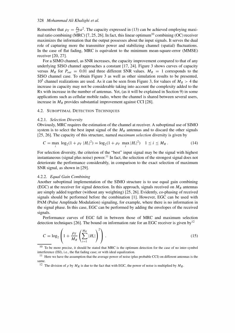
That is, for high SNR values, the capacity can be increased almost linearly with M. Figure 6shows capacity curves versus M = MR = MT for several SNR values in the case of Rayleighfading. It is seen that even for low SNR values, the increase in capacity is almost linear withincrease in M.
The gain in capacity compared to the SISO channel case can be considered to be composedof two components [18]; the array gain at Rx which corresponds to the gain in the averagepower of the signal combination on MR antennas, and the diversity gain which corresponds tothe gain from increasing the system dimensionality (rank of H ) and depends highly on spatialcorrelation between antenna signals or the correlation between hij as it will be explained inSubsection 8.1. The diversity gain is given by min(MR,MT ) under rich-scattering mediumconditions.15
With constant M, to see concretely how the capacity changes with an increase only inMR (or only in MT ), curves of capacity versus MR (or MT ) for MT = 4 (or MR = 4) areshown in Figure 7 for three SNR values. Cases of MR = 1 and MT = 1 represent MISO
13 Notice that here we have the assumption of flat channel. If the channel is frequency selective, the inserteddelay should be greater than the symbol duration plus the channel dispersion length [32].
14 This idea is generalized to the case of MIMO structure in [33] with (MT = 2,MR).15 It is interesting to know that if we want to profit from the maximum array gain, the transmission should be
performed only on the subchannel corresponding to the maximum λH,i singular value of H [18].
332 Mohammad Ali Khalighi et al.
Figure 6. Ideal MIMO structure; capacity curves versus number of antennas M = MR = MT , Pout = 0.01.
Figure 7. Ideal MIMO structure; capacity curves versus MR or MT ; MT or MR = 4, Pout = 0.01.
and SIMO channels, respectively. As expected, with constant M, the increase in MR is moreefficient regarding the resulting increase in capacity, than the increase in MT . In fact, withequal diversity order M, the case with MR > MT profits from more array gain at Rx. Notethat the increase in MR may imply more system implementation complexity too.
It should be insisted again that the results presented here are for the case of unknown chan-nel at transmitter. If channel is known at Tx, the limit of the MIMO capacity (obtained by waterfilling over the transmit antennas) is the same for (MR,MT ) and (MT ,MR) configurations.
6.1.2. Capacity versus SNRIf we define the capacity slope as the increase in capacity that results from the multiplicationof SNR by a factor η,
Slope(η) = C(η SNR) − C(SNR) (18)

Capacity of Wireless Communication Systems Employing Antenna Arrays 333
Figure 8. Ideal MIMO structure; capacity curves versus average SNR at receiver; M = MR = MT , Pout = 0.01.
it can be shown that [17, 24]
limρ→∞ Slope(η) = M log2 η . (19)
That is, under high SNR conditions, the capacity slope increases with increase in M. This canbe seen from Figure 8 that shows curves of capacity versus SNR for M = 2, 4, 6.
The RHS of (19) equals log2 η for a SIMO, MISO, or SISO channel.
6.1.3. Rationality of the Obtained CapacityThe obtained capacity improvement of MIMO systems may seem too large to be reasonable,regarding the number of constellation size that should be used to give the corresponding bitrates. However, it should be noticed that about 1
MTof total bit rate should be considered in the
design of signal constellations. In other words, the per dimension constellation size should beconsidered [5].
In contrast, SIMO systems may require a large and impractical constellation size for largechannel capacities (apart from the complexity of Rx due to the increased MR).
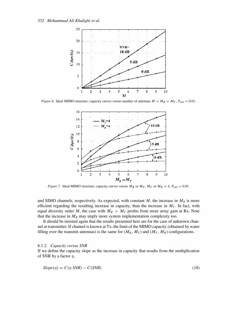
6.1.4. Optimum Selection of Transmit AntennasThe complexity of a MIMO system can be reduced by judicious selection of fewer transmitantennas without a considerable loss in the resulting channel capacity. Even, the capacity canbe increased! Consider MT transmit antennas in a MIMO structure. We select MS antennasamong MT for signal transmission, in such a way that the selected antennas result in maximumcapacity. This can be performed by an exhaustive search over all possible combinations oftransmit antennas. For example, simulation results are given in Figure 9 for a (4,4) Rayleighfading MIMO channel, where MS = 2 antennas are selected for signal transmission. It is seenthat for SNR <5 dB, signal transmission over MS “best” antennas results even in an increasein channel capacity, and for SNR < 10 dB, the difference in channel capacity is negligible,regarding the simplicity obtained.
A detailed analysis is performed in [34] on the effect of optimal selection of transmitantennas on channel capacity. Also, it is shown in [34, 35] that for a rank-deficient H (case of
334 Mohammad Ali Khalighi et al.
Figure 9. Optimal selection of MS among MT antennas for signal transmission, effect on MIMO channel capacity;MT = MR = 4, MS = 2, Pout = 0.01.
insufficient scatterers in the propagation medium), it is optimal or close to optimal to use asmany antennas for signal transmission as the rank of H .
Notice that this optimal selection is of particular interest. We know that the cost of Txis dominated by that of power amplifiers. Antennas are cheaper by typically two orders ofmagnitude [34]. So, it is economically advantageous to use a small number of amplifiers anda larger number of antennas, and to connect the amplifiers to a selected set of antennas16 toachieve the maximum possible system capacity.
The exhaustive search method stated above may be computationally intensive, especiallywhen MT and MS are relatively large. A computationally efficient near-optimal method ofselection of transmit antennas is proposed in [36], which is based on the knowledge of CSI atTx.
6.2. ATTEMPTS TO ATTAIN MIMO CAPACITY LIMITS
Equation (4) expresses the limit on information rate that can be ideally achieved in MIMOsystems. However, to achieve this capacity complicated coding/decoding techniques should beemployed. In particular, developing efficient spatio-temporal coding techniques has recentlybeen of special interest in attaining the MIMO channel capacity. We try to give basic resultsof the most recent works on this subject. Interested reader may refer to these papers and thereferences cited therein for detailed discussions.
6.2.1. BLAST ArchitectureOne efficient processing architecture proposed is the diagonal-BLAST or D-BLAST, devel-oped in Bell Labs and firstly presented by Foschini [37]. In this technique code blocks aredispersed across diagonals in space-time. MR = MT = M is taken.
It is known that M diversity antennas can null out up to M − 1 interferers [28]. In D-BLAST architecture, separately encoded M data blocks are transmitted on each antenna. Thatis, one-dimensional (1-D) encoders are used to encode the data transmitted from each transmit
16 Notice that it is well feasible under quasi-stationary conditions.

Capacity of Wireless Communication Systems Employing Antenna Arrays 335
antenna, and the M encoders are assumed to function without sharing any information witheach other. In each sequence duration, the receiver array detects the M received transmittedsequences : it nulls out the interference from yet undetected signals, and at the same timecancels out the interference from already-detected signals [37]. The order of detection is suchthat the sequence with higher SNR is detected first. In this way, the M-dimensional detectiontask is performed by M similar 1-D processing steps, and the Rx complexity grows onlylinearly with M.
Training sequences may be used to estimate the MIMO channel at Rx as considered in[38]. Notice that if joint detection of received signals is performed, as in multi-user detectionmethods, the complexity grows with mM , with m the signal constellation size [39].
The information rate bound for D-BLAST architecture is given by17 [37]
C =M∑k=1
log2
(1 + ρ
M
k∑i=1
|Hik|2). (20)
This capacity expression assumes perfect signal detection in already-processed layers, andhence, perfect cancellation of the contribution of the already-detected signals in the signal ofthe current layer being processed.
As it will be seen in the next section, the information rate bound approaches about 80% ofthe Shannon capacity given in (4). However, the implementation complexities of this approachhas made the Bell Labs researchers to develop a simplified version of D-BLAST, named verti-cal BLAST or V-BLAST [40, 41]. It seems to be the first realized MIMO system reported. Intheir prototype, an (MT ,MR) structure with 1 ≤ MT ≤ 8 and MT ≤ MR ≤ 12 is employed atfc = 1.9 GHz (carrier frequency) between fixed Tx-Rx in an indoor propagation environment,under the conditions of quasi-static flat fading. No coding is considered for transmitter signals.Similar to D-BLAST, interference nulling from undetected signals, interference cancellationfrom already detected signals, and detection ordering (detecting maximum SNR signal in eachstep) is performed.
The capacity bounds for V-BLAST architecture are studied in [42]. It is shown that theasymptotic capacity grows linearly with the number of antennas, and that large fractions ofD-BLAST rates (about 0.72 or even more, depending on the SNR) can be obtained with thissimple and flexible approach. Up to 16 transmit/receive antennas are employed in the work of[42], under the same conditions of [40, 41] stated above.
A problem with V/D-BLAST architectures is that the decision errors produced in eachlayer affect signal detection in subsequent layers, which is critical in low SNR. A more re-cent work realized by Ariyavisitakul uses BLAST architecture with space-time codes, whileapplying turbo (iterative) detection technique to avoid this error propagation [39]. His resultsshow that using space-time codes (almost similar to [43]) and turbo processing, the Shannoncapacity can be achieved within about 3 dB in average SNR. It is shown that for a largenumber of Tx and Rx antennas, coding across the layers provides a better performance thanindependent coding within each layer.
17 In fact, for k = M , any k entries of the kth column of H can be put in∑
i , depending on the order ofdetection.

336 Mohammad Ali Khalighi et al.
6.3. SPACE-TIME CODES
Space time codes are apparently developed independently from the works relating to BLASTproject. These codes firstly introduced by Tarokh et al. [43], combine spatial and temporaldiversity techniques. The input data sequence is encoded by the channel encoder, and then, theencoded data pass through a serial-to-parallel converter, which splits it into MT data streams.Each data stream is then transmitted simultaneously from different transmit antennas.18 Atthe receiver, on each antenna, a superposition of MT transmitted signals corrupted by noiseand fading is received. Trellis codes can be used with Viterbi decoding [7] at Rx, whereevidently the knowledge of H is necessary for computing branch metrics [43]. Under perfectchannel knowledge and quasi-static conditions, it is shown in [43] that performances aboutwithin 2.5 dB of the capacity can be obtained (see also [45] where non-ideal conditions areconsidered). It is discussed in [43] how tradeoff should be considered between transmissionrate, diversity advantage, signal constellation size, and trellis decoding complexity.
The case of large number of transmit antennas is considered in [46], where partitioning oftransmit antennas and using space-time codes on each group of antennas is proposed, whichhelps to reduce the Rx complexity.
The case of MIMO structures under frequency-selective fading conditions is consideredin [17, 24] (general comments on frequency-selective channels are given in Subsection 8.4).In [24] space-time vector coding (STVC) is proposed as a mean to approach to the channelcapacity.19 Notice that use of STVC necessitates the CSI knowledge at Tx. Also, a morepractical space-frequency coding structure named multivariate discrete multitone (MDMT) isproposed in [24] which has a considerable complexity reduction compared to STVC method.
In [17], MDMT is proposed together with multivariate trellis-codes modulation for thecase where Tx does not dispose the CSI. Using this coding technique, a MIMO structure isimplemented with 1 ≤ MT ≤ 3 and 1 ≤ MR ≤ 6 at fc = 5.2 GHz between mobile Tx-Rxwith a maximum Doppler of ±540 Hz [24].
The problem with trellis-based techniques is their decoding complexity. For a givennumber of transmit antennas, the decoding complexity of space-time trellis codes increasesexponentially with the diversity level and the transmission rate. In contrast to these codes,space-time block codes (STBC) proposed by [48] have the property of having a very simplemaximum likelihood decoding algorithm based on linear processing at Rx. These orthogonalcodes can be considered as a generalization of Alamouti transmission scheme [33] for anarbitrary number of transmit antennas. The performance of STBCs as well as coding/decodingaspects are discussed in [49].
6.4. SUBOPTIMAL STRUCTURE: SPATIAL CYCLING TECHNIQUE
One simple implementation of MIMO system is to use only one Tx at a time, and to cyclethrough all MT transmitters periodically with period of MT [5]. In other words, at each sampletime a SIMO structure is employed, and hence, it can be regarded as a generalized SIMOcase. Note that the detection complexity is as in the case of ideal (MRC) SIMO explainedin Section 4, but the transmitter is more complex here. With this technique, we profit from
18 Tx can insert periodic orthogonal pilot sequences in each simultaneously transmitted burst, to permit to Rxto estimate the channel [44].
19 This is a generalization of use of vector coding presented in [47] for the case of SISO frequency-selectivechannels.

Capacity of Wireless Communication Systems Employing Antenna Arrays 337
Figure 10. Spatial cycling MIMO structure; capacity curves versus MT ; SNR =10 dB, Pout = 0.01.
a simple implementation, there is no interference, and besides, the cycling ensures nontrivialdwelling on the better of MT transmitters. The capacity will be the average of capacities ineach Tx configuration [5].20
C = 1
MT
MT∑j=1
log2
(1 + ρT
MR∑i=1
|Hij |2)
bps/Hz . (21)
For four values of MR = 1, 2, 3, 4 curves of capacity versus MT are given in Figure 10 for aspatial cycling MIMO structure. Pout = 0.01 and SNR =10 dB is considered. It is seen thatusing just two antennas at Tx (MT = 2), an important increase can be obtained in capacity,as compared to ideal SIMO case (points of MT = 1 on the figure). Figure 11 contrasts valuesof capacity versus MR, for two cases of ideal SIMO system, and MIMO system with spatialcycling technique assuming MT = 2. Pout = 0.01 and SNR = 0, 5, 10 dB are considered.Also, CCDF curves of spatial cycling MIMO with MT = 2 are contrasted to other SIMOstructures in Figure 4.
6.5. SUBOPTIMAL DETECTION
To see the importance of use of an appropriate detection method, consider a very simplerealization of MIMO system. The same number of antennas is used at Tx and Rx, i.e., MT =MR = M is considered. The transmitted signal components are independently encoded; eachreceiver decodes the signal of one special antenna, and nulls out all signals that receives fromthe other antennas. We will call this detection method as independent detection. In this way,the capacity will be the sum of capacities of underlying SISO subchannels.21
C =M∑i=1
log2
(1 + ρT
MT
|Hii |2)
bps/Hz . (22)
20 Notice that the improvement achieved is in capacity-versus-outage, and the average capacity is obviously thesame as in SIMO case.
21 Here, we have supposed that the ith Rx decodes the signal of the ith Tx.

338 Mohammad Ali Khalighi et al.
Figure 11. Capacity at Pout = 0.01 for two cases of SIMO-MRC and MIMO-Spatial cycling with MT = 2.
Figure 12. MIMO structure with independent detection; capacity curves versus number of antennasM = MR = MT , Pout = 0.01.
Curves of capacity versus M are shown in Figure 12 for SNR = 0, 5, 10 dB and Pout = 0.01. Itis seen that although a MIMO structure is employed, the achieved capacity is not considerable.
Note that to achieve the capacity expressed in (22), different data rates should be used foreach one of the underlying SISO subchannels. In practice, however, it may not be realizable.If equal bit rates are to be used for all transmit antennas, the capacity will be M times theminimum of capacities of SISO subchannels [5]. This results in an even smaller capacity-versus-outage.
In fact, as it was seen, there is no interest to employ this detection technique in practice,and our aim was just to show the necessity of use of a suitable detection technique.
6.6. COMPARISON WITH SISO
Figure 13 contrasts curves of capacity for ideal/suboptimal MIMO with MR = MT = M =2, 4 and SISO structures. It is seen that the ideal MIMO capacity stands well superior to those

Capacity of Wireless Communication Systems Employing Antenna Arrays 339
Figure 13. CCDF capacity curves for SISO and different MIMO structures: ideal, D-BLAST architecture, in-dependent detection (Indep. Det.), spatial cycling (Sp. Cyc.) with MT = 2; SNR =10 dB; (a) M = 2, (b)M = 4.
of the suboptimal structures. On the other hand, the small variance of capacity in the case ofspatial cycling is noticeable (MT = 2 is taken for this case).
7. Comparison between Ideal SIMO, MISO, and MIMO Capacities
Figure 14 contrasts capacities of different antenna array structures versus number of antennaelements employed. M on the figure represents MT for MISO system, MR for SIMO system,and MT = MR for MIMO system (except for spatial cycling structure, where M = MR
and MT = 2). Ideal MISO structure is considered. For SIMO case, MRC and maximumselection detection techniques are taken. Also, for MIMO case, ideal detection, D-BLASTimplementation, independent detection, and spatial cycling with MT = 2 are considered. It isseen that the capacity of ideal MIMO stands well above those of MISO and SIMO structures.
As stated before, the D-BLAST architecture attains about 80% of the ideal MIMO capacity.The architecture of independent detection is practically of no interest; its capacity stands evenbelow the MRC SIMO case.
It is seen that for unknown channel at Tx, the capacity of ideal MISO system stands belowthat of SIMO system. As it was explained in Section 5, the advantage of SIMO system comesfrom the constraint on transmitted power. Note that even a SIMO system with maximumselection has a greater capacity than an ideal MISO system.
8. Some Practical Aspects
A series of assumptions was made in Section 2 for obtaining the results of previous sections.Here, we will review each assumption and will discuss its rationality, as well as the effect oncapacity when it is violated.
8.1. FADING CORRELATION AND ANTENNA ELEMENTS SPACING
In our analyses we assumed independent fading for each pair of Tx-Rx antennas, i.e., in-dependent entries for the channel matrix. However, in a real propagation environment, this

340 Mohammad Ali Khalighi et al.
Figure 14. Contrasting capacities of multiple-antenna structures: ideal MIMO, MIMO with D-BLAST, MIMOwith independent detection (Indep. Det.), MIMO with spatial cycling (Sp. Cyc.) with MT = 2, ideal (MRC)SIMO, maximum selection SIMO (Max. Sel.), and ideal MISO; Pout = 0.01, SNR = 10 dB.
assumption is not completely satisfied and some correlation exists between fadings of dif-ferent Tx-Rx antennas. In such a case, the capacity can be significantly smaller than in theindependent fading case. Note that (4) and (6) hold also in the case of correlated fading. Theeffect of fading correlation on the capacity of SIMO and MIMO systems is discussed in [50]and [21], respectively. We will treat these two cases briefly in the following.
8.1.1. SIMO SystemsThe independent fading assumption holds when multipath reflections are uniformly distributedaround the receiver antennas that are spaced at least λ/2 apart (λ is the wavelength) [26,50]. However, in some situations, signals arrive at the receiver antennas mainly from a givendirection. There exist situations where the angle of arrival (AOA) approaches endfire (parallelto the array, considering a linear array) and the beamwidth of incident waves decreases. Whenthe correlation is high (>0.8), the signals received on different antennas tend to fade at thesame time, and the diversity benefit of the antenna array against fading is significantly reduced[50]. In such cases, antenna spacing must be increased in order to reduce correlation.
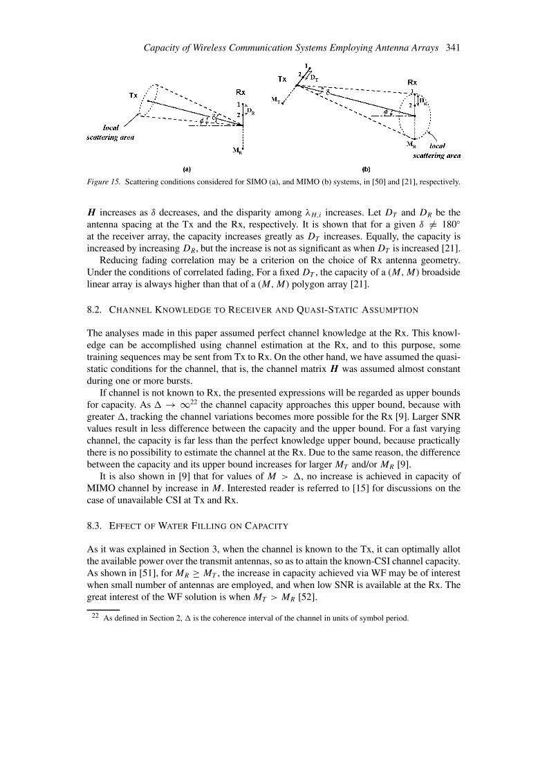
Consider the linear array at the receiver shown in Figure 15(a), where a local scattering isconsidered around the Tx [50]. φ is the AOA, δ the angle spread, and DR the antenna spacing(φ and δ are considered almost the same for all array elements).
When signal arrives from other than the broadside, i.e. φ = 0, the antenna spacing for lowcorrelation increases, and the envelope correlation is never zero for almost all values of φ = 0and δ < 180◦. The required spacing is only a few λ even for small δ, unless φ is close to 90◦[50].
8.1.2. MIMO SystemsShiu et al. have assumed in [21] that one of the communicating parties (for example the Tx) isnot obstructed by local scatterers, but the other one (the Rx) is surrounded by local scatterers.This case is shown in Figure 15(b). Here again, δ and φ are defined for whole transmit andreceive arrays. As the angle spread δ approaches zero, the capacity of the (M,M) MIMOsystem approaches to that of (1,M) SIMO system. The correlation between the columns of
Capacity of Wireless Communication Systems Employing Antenna Arrays 341
Figure 15. Scattering conditions considered for SIMO (a), and MIMO (b) systems, in [50] and [21], respectively.
H increases as δ decreases, and the disparity among λH,i increases. Let DT and DR be theantenna spacing at the Tx and the Rx, respectively. It is shown that for a given δ = 180◦at the receiver array, the capacity increases greatly as DT increases. Equally, the capacity isincreased by increasing DR, but the increase is not as significant as when DT is increased [21].
Reducing fading correlation may be a criterion on the choice of Rx antenna geometry.Under the conditions of correlated fading, For a fixed DT , the capacity of a (M,M) broadsidelinear array is always higher than that of a (M,M) polygon array [21].
8.2. CHANNEL KNOWLEDGE TO RECEIVER AND QUASI-STATIC ASSUMPTION
The analyses made in this paper assumed perfect channel knowledge at the Rx. This knowl-edge can be accomplished using channel estimation at the Rx, and to this purpose, sometraining sequences may be sent from Tx to Rx. On the other hand, we have assumed the quasi-static conditions for the channel, that is, the channel matrix H was assumed almost constantduring one or more bursts.
If channel is not known to Rx, the presented expressions will be regarded as upper boundsfor capacity. As � → ∞22 the channel capacity approaches this upper bound, because withgreater �, tracking the channel variations becomes more possible for the Rx [9]. Larger SNRvalues result in less difference between the capacity and the upper bound. For a fast varyingchannel, the capacity is far less than the perfect knowledge upper bound, because practicallythere is no possibility to estimate the channel at the Rx. Due to the same reason, the differencebetween the capacity and its upper bound increases for larger MT and/or MR [9].
It is also shown in [9] that for values of M > �, no increase is achieved in capacity ofMIMO channel by increase in M. Interested reader is referred to [15] for discussions on thecase of unavailable CSI at Tx and Rx.
8.3. EFFECT OF WATER FILLING ON CAPACITY
As it was explained in Section 3, when the channel is known to the Tx, it can optimally allotthe available power over the transmit antennas, so as to attain the known-CSI channel capacity.As shown in [51], for MR ≥ MT , the increase in capacity achieved via WF may be of interestwhen small number of antennas are employed, and when low SNR is available at the Rx. Thegreat interest of the WF solution is when MT > MR [52].
22 As defined in Section 2, � is the coherence interval of the channel in units of symbol period.

342 Mohammad Ali Khalighi et al.
Notice that in order to provide the CSI for the Tx, an additional radio link needs to beestablished from the Rx to the Tx, so as to provide the channel estimation information for theTx. From a practical point of view, this can be realized via a dedicated feedback channel orwhen the communication takes place in a duplex mode [14]. Note that such a feedback channelalready exists in power control schemes currently implemented in some cellular standards[53]. In practice, vehicle movements or interference causes a mismatch between the state ofthe channel received by Tx and that estimated in Rx [43].
If the channel is frequency selective, WF should be performed in space and time [24, 54]. Itis shown in [54] that the WF solution is much less interesting in this case, while the complexityof the realization is considerably greater.
Although WF at Tx may not be important regarding the increase in the channel capacity,in practice, knowledge of the channel can help us to perform beam forming on the transmitterarray, and so, to send the available power in appropriate directions and to increase the channelcapacity. This is not treated here, since we had assumed that no beam forming is performed atTx.
8.4. CHANNEL DISPERSION
In fact, channel dispersion can be regarded as another source of diversity, which can beexploited to combat fading, and hence to increase capacity [15, 26]. Evidently, this state-ment assumes perfect equalization at the Rx. Using a spatio-temporal channel model, it isshown in [54] how channel dispersion can increase the channel capacity. Also, an explicitexpression for capacity of MIMO frequency selective channels is given in [39] in terms of thefrequency-domain correlation matrix of signals received on Rx antennas.
Concerning MIMO structures, they have firstly been envisaged to be used in non-dispersivemedia, i.e., media satisfying flat fading conditions, or to be used under OFDM (orthogonalfrequency division multiplexing) signaling [17, 24]. That is because the equalization of MIMOchannels is a very complicated task, and adds a non-negligible complexity to the system.Recent works have proposed the use of channel shortening filters in order to facilitate the taskof channel equalization [55]. Also MMSE-DFE (decision feedback equalizer) equalizationstructures are studied in [56, 57].
With OFDM signaling, in the limiting case where the number of tones goes to infinity, thechannel capacity approaches that of the underlying time-dispersive channel [58].
Notice that even under narrow-band signal transmission (large symbol duration relative tothe channel delay spread), in practice some level of ISI is unavoidable due to the departureof the transmit and receive filters from their ideal Nyquist-based transfer functions [7, 42]. Infact, these filters have nonzero excess BW, and the resulting ISI should be cancelled.
8.5. NON-RAYLEIGH FADING CONDITIONS
Analyses of previous sections assumed Rayleigh fading conditions, which is valid for a richscattering wireless environment without any LOS between Tx and Rx. This is usually the casefor media such as troposcatter, cellular, and indoor radio [4, 59]. Sometimes, there are fewscatterers in the medium, and few multipaths contribute in signal propagation. For the numberof multipaths L, at high SNR, the capacity increases almost linearly with min(MT ,MR,L),which is the rank of H [24]. In the extreme case when there is no multipath (L = 1),rank(H ) = 1 and no transmit diversity can be exploited [61, 62].

Capacity of Wireless Communication Systems Employing Antenna Arrays 343
In real propagation environments, there may exist a LOS between Tx and Rx, or fixedscatteres/signal reflectors may exist in addition to random main scatterers. In such cases,Ricean fading conditions hold [7].23 It is shown in [61] that if the LOS contribution in signalpropagation is not very significant, the increase in capacity by an increase in the number ofantennas is still considerable.24
9. Multiuser Systems
Use of antenna arrays has recently been of special interest in multiuser systems. Althoughthe current debate in these systems is on the use of TDMA (time division multiple access)or CDMA (code division multiple access) to achieve high capacity, a substantial additionalgain in system capacity can be obtained by taking use of spatial diversity.25 As the multiuserapplications grow, the efficient use of spectral resources becomes more and more important.
The MIMO channel model is commonly used for many multiple access communicationscenarios such as, DS-CDMA (direct-sequence), cellular mobile system with antenna array atthe base station (BS), and multi-cellular system with joint multiuser detection [64].
Studying the capacity of these multi-user systems is beyond the scope of this paper, wetry just to discuss these systems globally and to give some most recent important papers asreference for interested readers.
In multiuser systems, the capacity is usually given for two cases of over-saturated andunder-saturated systems, where respectively, the number of users is greater than the systemdimension and otherwise.
Most of models presented for multiuser systems are basically single-user models, in thesense that the interfering users in non-orthogonal accessing protocols are considered as ad-ditive noise (and usually Gaussian). To see the works performed in this approach, see thereferences in [65]. For a multiple-access model, the capacity of simple cellular systems isgiven in [66] for the case of a discrete-time Gaussian channel with cell-by-cell separatedetection. The case of fading multiple-access channels is extensively studied in [65], whereprevious works can also be found in the references cited therein.
One special case is the case of RS-CDMA (random sequence) systems whose capacity isconsidered in [64, 67, 68]. In [68] the capacity is studied for different (suboptimal) detectiontechniques, and the gain resulting from optimal selection of random sequences is discussed.RS-CDMA with multiple antennas can be considered as to be equivalent to a multiuser systemwith antenna diversity and subject to channel fading [69].
Two important factors are the impact on capacity of the CSI information at Rx (which isaffected by the imperfect channel estimation) [70], and the knowledge of Rx on the SNR ofother interfering users [65].
Let us consider the case of cellular mobile radio and the use of multiple antennas in thesesystems in more detail. The general concept of application of antenna arrays in mobile com-
23 Also, Nakagami fading model parameterized by the fading severity parameter m fits well to some urbanmultipath propagation data, and in particular to microcellular radio environments [60].
24 Notice that LOS visibility is a desired parameter in radio mobile communication at high frequencies wherethe opacity of obstacles is high at high frequency bands and results in shadowing. If no LOS is available in general,fast power control algorithms and large dynamic ranges are necessary [63].
25 In general, spread spectrum systems can be considered as systems which profit from frequency diversity.However, when the coherence BW of the channel is larger than the spreading BW (case of small channel delayspread), these techniques become ineffective in combating fading effect [33].

344 Mohammad Ali Khalighi et al.
munication systems is extensively discussed in [1, 2]. Here, we will briefly discuss the case ofcellular systems from the point of view of system capacity.
In cellular mobile radio, use of multiple antenna is suggested at the BS to achieve moresystem capacity, as well as to permit more interference suppression capability [26, 28, 71–73].
Of interest is the technique called time division retransmission proposed in [28, 71]. Usingmultiple antennas at the BS and a single antenna at mobile, the adaptive signal processingis performed at the base station where its cost can be amortized among many mobiles. Dur-ing mobile-to-base transmission, the antenna elements weights are adjusted to maximize theSINR at the receiver output. During base-to-mobile transmission, the complex conjugate ofthe receiving weights are used, so that the signals from the base station antennas combine toenhance the reception of signal at the desired mobile and to reduce the power of this signalat other mobiles. In this way, as stated above, both the mobile and the base station receiversbenefit from OC (and ideally, MRC) with the complexity and multiple antennas at the basestation only [74].
Apart from the concept of capacity, an important interest of using multiple antennas is ininterference cancelling. Assuming that the BS uses MRC for signal detection, it is known thatusing MR antennas at the BS, we can profit from the nullification of Ni interferers, as well as(MR − Ni) diversity improvement against multipath fading [28]. This statement is also validin the case of frequency selective fading, provided that ideal equalization is performed at theBS [28].
Study of MIMO systems in a cellular mobile concept is performed in [75].At the BS, antennas are usually mounted above the clutter, and in order to have uncor-
related fading on the antennas, antenna spacings of the order of 10λ − 20λ (and even more,depending on the propagation conditions) should be used [26, 76]. A combination of spaceand polarization diversity may also be used, as considered in [77]. Notice that the interferencecancelling capability of a multi-antenna BS holds even under the condition of completelycorrelated fading on the antenna elements [50]. So, antenna elements can be placed with smallspacings, so as to permit an improvement in interference suppression, although they do notserve to reduce fading.
An interesting technique for limiting the adjacent cells’ interference is to use sectorizedantennas. For example using 120◦ beamwidth antennas, placed at three alternate corners ofhexagonal cells, the number of possible interferers is reduced by a factor of three [71].
Antenna arrays can also be used in the concept of space-division multiple access (SDMA),where cells are divided into sectors (by means of highly directive antennas) in order to permitthe reuse of the BW in the mutual interference-free sectors. In other words, each sector canbe treated as a separate cell, and the frequency assignment may be performed in the usualmanner. Mobiles are handled to the next sector as they leave the area covered by the currentsector, as is done in a normal handoff process when mobiles cross the cell boundary [1].26
Using sectorization, the problem of delay spread can be reduced noticeably too [74]. Capacityof mobile cellular radio SDMA systems is studied in [78].
26 In total, increasing the system capacity by means of directive antennas results in a reduced required handoffrate in comparison to the conventional cell splitting technique.

Capacity of Wireless Communication Systems Employing Antenna Arrays 345
10. Conclusion
The increasing demand for bandwidth in wireless networks may be satisfied by increasingthe signal power and use of high gain antennas. However, in many applications, this is notthe best solution, especially when we are faced to a randomly time-varying channel. Undersuch conditions, the most important techniques in providing reliable communication overwireless channels are diversity techniques, and of particular interest are the spatial diver-sity techniques. We have attempted in this paper to provide a clear image of the effect ofusing multiple antennas on the capacity of wireless communication systems. Three generalstructures of multi-antenna systems, i.e., SIMO, MISO, and MIMO structures were studiedextensively, and several useful performance curves were provided. Moreover, the capacity ofseveral suboptimal structures were studied and the increases in capacity of different structureswith increase in the number of antennas were contrasted together.
The presented results were conditioned to some assumptions, particularly regarding chan-nel fading. We have reviewed each assumption and explained its rationality in usual practicalsituations, as well as deteriorations in the presented results in the case of violation of theassumption.
If antenna elements are spaced sufficiently apart, use of multiple antenna elements at Rxis very effective in combating signal fading, as well as in interference cancellation whenthe channel BW is shared among several users. On the other hand, use of multiple antennaelements at both Tx and Rx makes it possible to attain high information rates in a richscattering environment. In this case, the channel capacity can be considerably increased byadding antenna elements at both sides of the radio link. In fact, one can speak of multipathexploitation instead of multipath mitigation. Some key applications are fixed wireless andwireless LANs (Local Area Network).
The possibility of increasing the number of antennas in order to increase the channelcapacity depends on the desired system complexity and cost, as well as the permitted sizeof Tx/Rx modules. Notice that use of multiple antennas requires circuitry in each diversitybranch, resulting in an increased cost and power consumption, as well as the unit size. Useof higher frequencies may be a solution since it permits using smaller antennas and antennaspacings.
However, the serious problem is the system complexity, from the points of view of channelcoding/decoding, detection, and synchronization. Especially, for MIMO systems, the prob-lems such as efficient spatio-temporal coding and channel equalization/estimation, make itsimplementation very complex. Other complexities arise from timing errors, phase noise, andcarrier frequency offset common in most wireless communication systems, which degradethe performance in practice. Fading correlation can also cause significant degradation inperformance, as explained previously.
There stays still a large area of research on the implication of antenna arrays in futurecommunication systems. Of particular is to improve the quality and the spectral efficiencyof wireless systems by developing efficient modulation, coding, and signal processing tech-niques. Also, in multiuser systems, developing efficient techniques for sharing the availablespectrum among different users, and particularly robust receiver design to confront thestructured interference from other users of the multi-access channel, are important researchsubjects.
More specifically, about signal processing techniques in MIMO systems, current re-searches consider the implementation of MIMO wireless systems under OFDM signaling,

346 Mohammad Ali Khalighi et al.
the equalization of MIMO channels under delay-dispersive channel conditions, and more im-portant, the elaboration of new efficient, yet computationally reasonable detection techniquesand space-time codes in order to increase the spectral efficiency. Although the use of MIMOstructures for communication between two points seems too complicated now, they are veryinteresting candidates for short future high bit rate communication systems.
Use of antenna arrays is also of special interest in the context of new generations of mobilesystems, such as EDGE (Enhanced Data GSM Environment), IS-136, and UMTS (UniversalMobile Telecommunication System). The rising demand for personal communication servicesneeds high data rate and high quality information exchange between portable terminals. Newstandards for the third generation (3G) of mobile systems which are very different from thoseof the current systems [63, 79] will necessitate the development of more efficient signalprocessing techniques.
It seems that more plausible trade space to satisfy the requirements of the 3G wirelesssystems are the base stations, rather than portable telephones. For the latter, there exist morelimitations, particularly due to the limited size, and the requirement of powerful hardware forsignal processing requirement. Also, efficient signal processing techniques which require sig-nificant processing power can not be used for low power devices, although advances in VLSI(Very Large Scale Integration) and integrated circuit technology for low power applicationswill provide a partial solution to this problem.
Use of multiple antenna systems is also an interesting subject in applications such as HFcommunication and submarine acoustics, where a serious limitation exists on the availablechannel bandwidth. Also, as pointed out previously, multiple antennas can be used in multi-access channels (TDMA or CDMA) as well as in multi-carrier systems to attain additionalchannel capacity and improvement in the system performance. Antenna arrays may also beused in geographically different locations, usually referred to as macro-diversity or distributedantenna systems, in order to combat larger scale fading effects.
On the whole, future wireless communication systems will perform a breakthrough insystem performance, by taking use of antenna arrays at both sides of the communication link.Current researches focus on the design of new architectures that can take use of this potentialcapacity as much as possible. We conclude this paper with the statement of Marconi in 1932that, “It is dangerous to put limits on wireless”.
References
1. L.C. Godara, “Applications of Antenna Arrays to Mobile Communications, Part I: Performance Improve-ment, Feasibility, and System Considerations”, Proceedings of the IEEE, Vol. 85, No. 7, pp. 1031–1060,1997.
2. L.C. Godara, “Applications of Antenna Arrays to Mobile Communications, Part II: Beam-Forming andDirection-of-Arrival Considerations”, Proceedings of the IEEE, Vol. 85, No. 8, pp. 1193–1245, 1997.
3. K. Pahlavan and A.H. Levesque, “Wireless Data Communications”, Proceedings of the IEEE, Vol. 82, No. 9,pp. 1398–1430, 1994.
4. B. Sklar, “Rayleigh Fading Channels in Mobile Digital Communication Systems; Part I: Characterization;Part II: Mitigation”, IEEE Communication Magazine, Vol. 35, No. 7, pp. 90–109, 1997.
5. G.J. Foschini and M.J. Gans, “On Limits of Wireless Communications in a Fading Environment when UsingMultiple Antennas”, Wireless Personal Communications, Vol. 6, No. 3, pp. 311–335, 1998.
6. BLAST: Bell Labs Layered Space-Time, Bell Labs projects, http://www.bell-labs.com/project/blast/7. J.G. Proakis, Digital Communications, McGraw Hill, 2nd edn, 1989.8. F.D. Neeser and J.L. Massey, “Proper Complex Random Proccesses with Applications to Information
Theory”, IEEE Transactions on Information Theory, Vol. IT-39, No. 4, pp. 1293–1302, 1993.

Capacity of Wireless Communication Systems Employing Antenna Arrays 347
9. T.L. Marzetta and B.M. Hochwald, “Capacity of a Mobile Multiple-Antenna Communication Link inRayleigh Flat Fading”, IEEE Transactions on Information Theory, Vol. IT-45, No. 1, pp. 139–157, 1999.
10. C.E. Shannon, “Communication in the Presence of Noise”, Proceedings of the IRE, Vol. 37, No. 1, pp. 10–21,1949. Reprinted as “classic paper” in Proceedings of the IEEE, Vol. 86, No. 2, pp. 447–457, 1998.
11. E. Telater, “Capacity of Multi-Antenna Gaussian Channel”, AT&T Bell Labs, Tech. Memo., June 1995.12. E. Telatar, “Capacity of Multi-Antenna Gaussian Channels”, invited paper, European Transactions on
Telecommunications, Vol. ETT-10, No. 6, pp. 585–595, 1999.13. G. Caire and S. Shamai (Shitz), “On the Capacity of Some Channels with Channel State Information”, in
IEEE Transactions on Information Theory, Vol. IT-45, No. 6, pp. 2007–2019, 1999.14. G. Caire, G. Taricco and E. Biglieri, “Optimum Power Control over Fading Channels”, IEEE Transactions
on Information Theory, Vol. IT-45, No. 5, pp. 1468–1489, 1999.15. E. Biglieri, J. Proakis and S. Shamai (Shitz), “Fading Channels, Information-Theoretic and Communications
Aspects”, invited paper, IEEE Transactions on Information Theory, Vol. IT-44, No. 6, pp. 2619–2692, 1998.16. A. Lapidoth and P. Narayan, “Reliable Communication under Channel Uncertainty”, invited paper, IEEE
Transactions on Information Theory, Vol. IT-44, No. 6, pp. 2148–2177, 1998.17. G.G. Raleigh and V.K. Jones, “Multivariate Modulation and Coding for Wireless Communication”, IEEE
Journal on Selected Areas in Communications, Vol. SAC-17, No. 5, pp. 851–866, 1999.18. J.B. Anderson, “Array Gain and Capacity for Known Random Channels with Multiple Element Arrays at
Both Ends”, IEEE Journal on Selected Areas in Communications, Vol. SAC-18, No. 11, pp. 2172–2178,2000.
19. P. Balaban and J. Salz, “Optimum Diversity Combining and Equalization in Digital Data Transmission withApplication to Cellular Mobile Radio-Part 1 and 2”, IEEE Transactions on Communications, Vol. COM-40,No. 5, pp. 885–907, 1992.
20. J.H. Winters, “On the Capacity of Radio Communication Systems with Diversity in a Rayleigh FadingEnvironment”, IEEE Journal on Selected Areas in Communications, Vol. SAC-5, No. 5, pp. 871–878, 1987.
21. D. Shiu, G.J. Foschini, M.J. Gans and J.M. Kahn, “Fading Correlation and Its Effect on the Capacity of Multi-Element Antenna Systems”, IEEE Transactions on Communications, Vol. COM-48, No. 3, pp. 502–513,2000.
22. H. Viswanathan, “Capacity of Markov Channels with Receiver CSI and Delayed Feedback”, IEEETransactions on Information Theory, Vol. IT-45, No. 2, pp. 761–771, 1999.
23. A. Goldsmith and P. Varaiya, “Capacity of Fading Channels with Channel Side Information”, IEEETransactions on Information Theory, Vol. 43, No. 6, pp. 1986–1992, 1997.
24. G.G. Raleigh and J.M. Cioffi, “Spatio-Temporal Coding for Wireless Communication”, IEEE Transactionson Communications, Vol. COM-46, No. 3, pp. 357–366, 1998.
25. D. Brennan, “Linear Diversity Combining Techniques”, Proceedings of the IRE, Vol. 47, pp. 1075–1102,1959.
26. W.C. Jakes, Microwave Mobile Communications, John Wiley & Sons, New York, 1974. Reprinted by IEEEPress, 1998.
27. M.V. Clark, L.J. Greenstein, W.K. Kennedy and M. Shafi, “MMSE Diversity Combining for Wide-BandDigital Cellular Radio,” IEEE Transactions on Communications, Vol. COM-40, No. 6, pp. 1128–1135, 1992.
28. J.H. Winters, J. Salz and R.D. Giltin, “The Impact of Antenna Diversity on the Capacity of Wireless Com-munication Systems”, IEEE Transactions on Communications, Vol. COM-42, Nos. 2–4, pp. 1740–1750,1994.
29. G. Chyi, J.G. Proakis and C.M. Keller, “On the Symbol Error Probability of Maximum-Selection DiversityReception Schemes over a Rayleigh Fading Channel”, IEEE Transactions on Communications, Vol. COM-37, No. 1, pp. 79–83, 1989.
30. A. Wittenben, “A New Bandwidth Efficient Transmit Antenna Modulation Diversity Scheme for LinearDigital Modulation”, in Proceedings of 1993 IEEE International Conference on Communications, ICC, May1993, pp. 1630–1634.
31. N. Seshadri and J.H. Winters, “Two Signaling Schemes for Improving the Error Performance of FDD Trans-mission Systems Using Transitter Antenna Diversity”, in Proceedings of 43rd IEEE Vehicular TechnologyConference, VTC, May 1993, pp. 508–511.
32. J.H. Winters, “The Diversity Gain of Transmit Diversity in Wireless Systems with Rayleigh Fading”, IEEETransactions on Vehicular Technology, Vol. VT-47, No. 1, pp. 119–123, 1998.

348 Mohammad Ali Khalighi et al.
33. S.M. Alamouti, “A Simple Transmit Diversity Technique for Wireless Communications”, IEEE Journal onSelected Areas in Communications, Vol. SAC-16, No. 8, pp. 1451–1458, 1998.
34. R.U. Nabar, D.A. Gore and A. Paulraj, “Optimal Selection and Use of Transmit Antennas in Wireless Sys-tems”, in Proceedings of International Conference on Telecommunications, ICT, Acapulco, Mexico, U.S.A.,May 2000.
35. D.A. Gore, R.U. Nabar and A. Paulraj, “Selecting an Optimal Set of Transmit Antennas for a Low RankMatrix Channel”, in Proceedings of IEEE Conference on Acoustics, Speech, and Signal Processing, ICASSP,Istanbul, Turkey, June 2000, pp. 2785–2788.
36. S. Sandhu, R.U. Nabar, D.A. Gore and A. Paulraj, “Near-Optimal Selection of Transmit Antennas for aMIMO Channel Based on Shannon Capacity”, in Proceedings of 34th Asilomar Conference on Signals,Systems, and Computers, Pacific Grove, CA, U.S.A., 2000, Vol. 1, pp. 567–571.
37. G.J. Foschini, “Layered Space-Time Architecture for Wireless Communication in a Fading Environmentwhen Using Multi-Element Antennas”, Bell Labs Technical Journal, Vol. 1, No. 2, pp. 41–59, 1996.
38. T.L. Marzetta, “BLAST Training: Estimating Channel Characteristics for High Capacity Space-Time Wire-less”, in Proceedings of 37th Annual Allenton Conference on Communication, Control, and Computing,Monticello, IL, Sept. 1999, pp. 958–966.
39. S.L. Ariyavisitakul, “Turbo Space-Time Processing to Improve Wireless Channel Capacity”, IEEE Transac-tions on Communications, Vol. COM-48, No. 8, pp. 1347–1359, 2000.
40. P.W. Wolniansky, G.J. Foschini, G.D. Golden and R.A. Valenzuela, “V-BLAST: An Architecture for Real-izing Very High Data Rates over the Rich-Scattering Wireless Channel”, in Proceedings of ISSSE-98, Pisa,Italy, Sept. 1998.
41. G.D. Golden, G.J. Foschini, R.A. Valenzuela and P.W. Wolniansky, “Detection Algorithm and Initial Labora-tory Results Using V-BLAST Space-Time Communication Architecture”, Electronic Letters, Vol. 35, No. 1,pp. 14–16, 1999.
42. G.J. Foschini, G.D. Golden, R.A. Valenzuela and P.W. Wolniansky, “Simplified Processing for High Spec-tral Efficiency Communication Employing Multi-Element Arrays”, IEEE Journal on Selected Areas inCommunications, Vol. SAC-17, No. 11, pp. 1841–1852, 1999.
43. V. Tarokh, N. Seshadri and A.R. Calderbank, “Space-Time Codes for High Data Rate Wireless Communica-tion: Performance Criterion and Code Construction”, IEEE Transactions on Information Theory, Vol. IT-44,No. 2, pp. 744–765, 1998.
44. A. Naguib, V. Tarokh, N. Seshadri and A.R. Calderbank, “A Space-Time Coded Modem for High DataRate Wireless Communication”, IEEE Journal on Selected Areas in Communications, Vol. SAC-16, No. 8,pp. 1459–1478, 1998.
45. V. Tarokh, A. Naguib, N. Seshadri and A.R. Calderbank, “Space-Time Codes for High Data Rate WirelessCommunication: Performance Criteria in the Presence of Channel Estimation Errors, Mobility, and MultiplePaths”, IEEE Transactions on Communications, Vol. COM-47, No. 2, pp. 199–207, 1999.
46. V. Tarokh, A. Naguib, N. Seshadri and A.R. Calderbank, “Combined Array Processing and Space-TimeCoding”, IEEE Transactions on Information Theory, Vol. IT-45, No. 4, pp. 1121–1128, 1999.
47. S. Kasturia, J. Aslanis and J.M. Cioffi, “Vector Coding for Partial Response Channels”, IEEE Transactionson Information Theory, Vol. IT-36, pp. 741–762, 1990.
48. V. Tarokh, H. Jafarkhani and A.R. Calderbank, “Space-Time Block Codes from Orthogonal Designs”, IEEETransactions on Information Theory, Vol. IT-45, No. 5, pp. 1456–1467, 1999.
49. V. Tarokh, H. Jafarkhani and A.R. Calderbank, “Space-Time Block Coding for Wireless Communications:Performance Results”, IEEE Journal on Selected Areas in Communications, Vol. SAC-17, No. 3, pp. 451–460, 1999.
50. J. Salz and J.H. Winters, “Effect of Fading Correlation on Adaptive Arrays in Digital Mobile Radio”, IEEETransactions on Vehicular Technology, Vol. VT-43, No. 4, pp. 1049–1057, 1994.
51. M.A. Khalighi, J.M. Brossier, G. Jourdain and K. Raoof, “Water Filling Capacity of Rayleigh MIMOChannels”, in Proceedings of PIMRC 2001, San Diego, CA, 30 Sept.–3 Oct. 2001, Vol. A, pp. 155–158.
52. M.A. Khalighi and G. Jourdain, “Increase in the Capacity of Transmit Diversity Systems by Optimal PowerAllotment at Transmitter”, submitted to EURASIP Journal of Applied Signal Processing.
53. T. Rappaport, Wireless Communications, Englewood Cliffs, NJ, Prentice-Hall, 1996.54. M.A. Khalighi, K. Raoof and G. Jourdain, “Capacity of Multi-Antenna Time-Dispersive Channels Subject
to Fading”, in Proceedings of 18th GRETSI, Toulouse, France, 10–13 Sept. 2001, pp. 129–132.
Capacity of Wireless Communication Systems Employing Antenna Arrays 349
55. N. Al-Dhahir, “FIR Channel-Shortening Equalizers for MIMO ISI Channels”, IEEE Transactions onCommunications, Vol. 49, No. 2, pp. 213–218, 2001.
56. N. Al-Dhahir and A.H. Sayed, “The Finite-Length MIMO MMSE-DFE”, IEEE Transactions on SignalProcessing, Vol. SP-48, No. 10, pp. 2921–2936, 2000.
57. N. Al-Dhahir, A.F. Naguib and A.R. Calderbank, “Finite-Length MIMO Decision Feedback Equalizationfor Space-Time Block-Coded Signals over Multipath-Fading Channels”, IEEE Transactions on VehicularTechnology, Vol. VT-50, No. 4, pp. 1176–1182, 2001.
58. H. Bölcskei, D. Gesbert and A.J. Paularj, “On the Capacity of OFDM-Based Multi-Antenna Systems”, inProceedings of ICASSP 2000, Istanbul, Turkey, pp. 2569–2572, 2000.
59. H. Hashemi, “The Indoor Radio Propagation Channel”, Proceedings of the IEEE, Vol. 81, No. 7, pp. 943–968, 1993.
60. H. Suzuki, “A Statistical Model for Urban Multipath Propagation”, IEEE Transactions on Communications,Vol. COM-25, No. 7, pp. 673–680, 1977.
61. M.A. Khalighi, J.M. Brossier, G. Jourdain and K. Raoof, “On Capacity of Ricean MIMO Channels”, inProceedings of PIMRC 2001, San Diego, CA, 30 Sept.–3 Oct. 2001, Vol. A, pp. 150–154.
62. P.F. Driessen and G.J. Foschini, “On the Capacity Formula for Multiple Input-Multiple Output WirelessChannels: A Geometric Interpretation”, IEEE Transactions on Communications, Vol. COM-47, No. 2,pp. 173–176, 1999.
63. M. Dinis and J. Fernandes, “Life after Third-Generation Mobile Communications; Provision of SufficientTransmission Capacity for Broadband Mobile Multimedia: A Step toward 4G”, IEEE CommunicationMagazine, Vol. 39, No. 8, pp. 46–54, 2001.
64. P.B. Rapajic and D. Popescu, “Information Capacity of a Random Signature Multiple-Input Multiple-OutputChannel”, IEEE Transactions on Communications, Vol. COM-48, No. 8, pp. 1245–1248, 2000.
65. S. Shamai (Shitz) and A.D. Wyner, “Information-Theoretic Considerations for Symmetric, Cellular,Multiple-Access Fading Channels, Parts I and II”, IEEE Transactions on Information Theory, Vol. IT-43,No. 6, pp. 1877–1911, 1997.
66. A.D. Wyner, “Shannon-Theoretic Approach to a Gaussian Cellular Multiple-Access Channel”, IEEETransactions on Information Theory, Vol. IT-40, No. 6, pp. 1713–1727, 1994.
67. A.J. Grant and P.D. Alexander, “Random Sequense Multisets for Synchrounous Code-Division Multiple-Access Channels”, IEEE Transactions on Information Theory, Vol. IT-44, No. 7, pp. 2832–2836, 1998.
68. S. Verdù and S. Shamai (Shitz), “Spectral Efficiency of CDMA with Random Spreading”, IEEE Transactionson Information Theory, Vol. IT-45, No. 2, pp. 622–640, 1999.
69. D.N.C. Tse and O. Zeitouni, “Linear Multiuser Receivers in Random Environments”, IEEE Transactions onInformation Theory, Vol. IT-46, No. 1, pp. 171–188, 2000.
70. J. Evans and D.N.C. Tse, “Large System Performance of Linear Multiuser Receivers in Multipath FadingChannels”, IEEE Transactions on Information Theory, Vol. IT-46, No. 6, pp. 2059–2078, 2000.
71. P.S. Henry and B.S. Glance, “A New Approach to High-Capacity Digital Mobile Radio”, The Bell SystemTechnical Journal, Vol. 60, No. 8, pp. 1891–1904, 1981.
72. W.C.Y. Lee, Mobile Cellular Telecommunications, McGraw Hill, 2nd edn, 1995.73. F. Fujimoto and J.R. James, Mobile Antenna Systems Handbook, Artech House, 1994.74. M.A. Khalighi, “Capacity of Communication Systems Using Multi-Element Array Antenna”, Internal
Report No. 10/2000, LIS laboratory, Feb. 2000.75. S. Catreux, “Multiple Input-Multiple Output Antenna Techniques in Cellular Systems”, Ph.D. Thesis,
National Institute of Applied Sciences (INSA), Rennes, France, Mar. 2000.76. W.C.Y. Lee, “Effects on Correlation between Two Mobile Radio Base-Station Antennas”, IEEE Transactions
on Communications, Vol. COM-21, No. 11, pp. 1214–1224, 1973.77. C.C. Martin, N.R. Sollenberger and J.H. Winters, “Field Test Results of Downlink Smart Antennas and
Power Control for IS-136”, in Proceedings of IEEE 49th Vehicular Technology Conference (VTC), Houston,TX, May 16–20, 1999, Vol. 1, pp. 453–457.
78. P.B. Rapajic, “Information Capacity of the Space Time Division Multiple Access Mobile CommunicationSystem”, Wireless Personal Communications, Vol. 11, No. 1, pp. 131–159, 1999.
79. M. Zeng, A. Annamalai and V.K. Bhargava, “Recent Advances in Cellular Wireless Communications”, IEEECommunication Magazine, Vol. 37, No. 9, pp. 128–138, 1999.
80. T.M. Cover and J.A. Thomas, Elements of Information Theory, John Wiley & Sons, 1991.

350 Mohammad Ali Khalighi et al.
Appendix: Proof of Capacity Expressions
In this appendix we give the proofs of the capacity expressions given in (4) and (6) for thecase of non-dispersive channel.
Let RZ, RY , and Rn be the autocorrelation matrices of the vectors z, y, and n, respectively,defined by (1). The input power constraint can be considered as tr(RX) ≤ PT with tr(.) thetrace of matrix. The capacity of the Gaussian channel can be written as follows.
C = maxpdf of x
[h(y)] − h(n) (23)
h(.) is the differential entropy. The maximum of h(y) is for Gaussian y which is achievedwhen x is Gaussian. Consequently [80],
C = maxRX
log2det(RZ)
det(Rn)= max
RX
log2det(RY + Rn)
det(Rn). (24)
Here det(.) denotes matrix determinant. As denoted, the maximization should be performedover RX. Consider the SVD of H as H = UH�HV
†H . We have
RY = a2UH�HV†HRXV H�
†HU
†H . (25)
On the other hand, Rn = σ 2I . So, the problem is to maximize det(RY + Rn), or equivalentlyto maximize
det[a2�HV†HRXV H�
†H + σ 2I ] = det(B) , (26)
where we have named the matrix in the brackets as B. We know that for a positive definedsquare matrix A we can write det(A) ≤ ∏
i Aii . In other words, for a family of matrices A
with the same diagonal entries of Aii , the maximum determinant is obtained for the diagonalmatrix. So, to maximize det(B), we choose RX = V HP XV
†H , with PX a diagonal matrix
with elements of λX,i (positioned on the matrix diagonal in descending order). In this way,λX,i will be the eigenvalues of the matrix RX.
If no CSI is available, the reasonable choice is to allot the available power equally over thetransmit antennas, that is, to take equal λX,i. In this way, RX = PT
MTI with I is the identity
matrix. With this choice, (24) reduces to the expression of (4). Notice that this choice of RX
implies independent Gaussian signals on transmit antennas.If CSI is provided at the transmitter, we have,
det(B) = (σ 2)|MT −MR |M∏i=1
(a2λX,i λ2H,i + σ 2) , (27)
where | · | denotes the absolute value operator, and M = min(MT ,MR). Now to furthermaximize det(B), we can apply the method of Lagrange multipliers to the right side of (27).
f =M∏i=1
(a2λX,iλ2H,i + σ 2) + θ
(MT∑i=1
λX,i − PT
); ∂f
∂λX,i= 0 .
It can be easily shown that this maximization results in the WF solution given by (6) and (7).

Capacity of Wireless Communication Systems Employing Antenna Arrays 351
Mohammed Ali Khalighi was born in Kerman, Iran, on 5 March 1975. He received his B.Sc.and M.Sc. degrees in Electrical Engieneering from Sharif University of Technology, Teheran,Iran, in 1995 and 1997, respectively. He worked as a design engineer at the department ofelectrical engineering of Sharif University from 1997 to 1998. He also received M.Sc. degreeon signal processing from INPG (Institut National Polytechnique de Grenoble), Grenoble,France, in 1999. He is now a Ph.D. candidate at INPG. His main interests are in electronicinstrumentation, high speed analog and digital circuitry, and digital signal processing with ap-plication to communication systems. His current research fields include information theoreticaspects, coding and equalization in multiple antenna wireless communication systems. Mr.Khalighi is quoted in “Who’s Who in Science and Engineering”.
Kosai Raoof is a member of the communication group of LIS laboratory. He received hisB.Sc. in electronics and electrical engineering from Baghdad University, Irak, in 1985, andM.Sc. in signal and image processing in 1989 from Institut Polytechnique de Grenoble,France. He also received his Ph.D. and DHDR in 1993 and 1998, respectively, from Uni-versité Joseph Fourier, Grenoble, France. Since 1993 he has been an associate professor atUniversité Joseph Fourier – Institut des Sciences et Techniques de Grenoble. To date he haspublished more than 25 papers in international journals and refereed international conferenceproceedings. He has been the supervisor of several M.Sc. and Ph.D. students. His researchinterests include robust signal synchronization in WCDMA systems, as well as developingnew adaptive multidimensional techniques to enhance signal to noise ratio in applicationssuch as biomedical, NMRI, and telecommunication systems.

352 Mohammad Ali Khalighi et al.
Geneviève Jourdain is Professor at INPG. Her research activities are focused on the var-ious following themes concerning Signal Processing and Digital Communication: time andfrequency characterisation of targets and channels; detection and estimation; communicationreceivers after multipath channels, multichannel equalization and CDMA systems; underwatercommunication and radio mobile communication (UMTS). She is author of about 80 pub-lications or communications in international papers or conferences. She has been Head ofCEPHAG Laboratory from 1990 to 1997. She is member of various French Signal ProcessingGroups; she is IEEE Senior Member and referee for many international papers.