Embed Size (px)
Citation preview

CAPACITORS FOR POWER ELECTRONICS
Westcode Semiconductors Ltd Issue 4 – August 2004

CAPACITORS FOR POWER ELECTRONICS
Westcode Semiconductors Ltd Issue 4 – August 2004
Table of contents page
1. Introduction 2
2. Applications & Definitions 3
3. Capacitor Construction 5
4. Safety 5
5. Operating life 6
6. Mounting and operating instructions 7
7. Calculation example 8
8. List of abbreviations 10
9. Capacitor Data Tables 11
10. Outline Drawings 29
11. Contact Details t.b.a*
* As per Distributor/Representatives Listing in New Selector Guide

CAPACITORS FOR POWER ELECTRONICS
Westcode Semiconductors Ltd Issue 4 – August 2004
1. IntroductionEnjoying a reputation as one of the World’s leading manufacturers of power semiconductors with its originsin the 1920s, Westcode employs almost 300 people in the research, development, manufacture andmarketing of silicon power products.
This catalogue details the Westcode range of power electronics capacitors for both Ac and DC applicationsand a variety of purposes which include filtering, smoothing, supporting, snubbing/clamping, commutationand general use. For information on application specific capacitors, GTO and IGBT snubbers and mediumfrequency capacitors, for induction heating processes, please contact either your localrepresentative/distributor or our Sales Office, details at the end of this brochure.
2. ApplicationCapacitors for power electronics can be used for a wide variety of applications, even where extremely non-sinusoidal voltages and pulsed currents are present. Both AC and DC capacitors are available. ACcapacitors are periodically recharged during operation, DC capacitors are periodically charged anddischarged without recharge.
Typical Voltage characteristics:
AC Application DC Application
Main Applications:
Damping or Snubber Capacitors (AC) are usually connected in series with a resistor, and are designedfor the damping of undesirable voltage spikes caused by the so-called carrier storage effect during theswitching of power semiconductors.
Commutation Capacitors (AC) are switched in parallel to a thyristor and designed to quench itsconductive state. Since commutating capacitors are periodically and abruptly recharged, the peak currentmay substantially exceed the rms value.
Smoothing Capacitors (DC) serve for the reduction of the AC component of fluctuating DC voltage in,for example;- power supplies in radio and television technology (transmitters),- high-voltage testing equipment, DC controllers,- measurement and control technology, and- cascaded circuits for generation of high DC voltage.
Supporting Capacitors, DC-Filter or Intermediate Circuit Capacitors (DC) are used for energystorage in intermediate DC circuits. They must be able to absorb and release very high currents withinshort periods, the peak value of the current being substantially greater than the rms value.
Examples of application:- frequency converters for poly-phase drives- transistor and thyristor converters
CAPACITORS FOR POWER ELECTRONICS
Westcode Semiconductors Ltd Issue 4 – August 2004
Surge (Pulse) Discharge Capacitors (DC) are capable of supplying or absorbing extreme short-timecurrent surges. They are usually operated at low repetition frequencies.
Examples of application:- laser technology- lightning generators- magnetising equipment
Definitions:In accordance with IEC 1071.
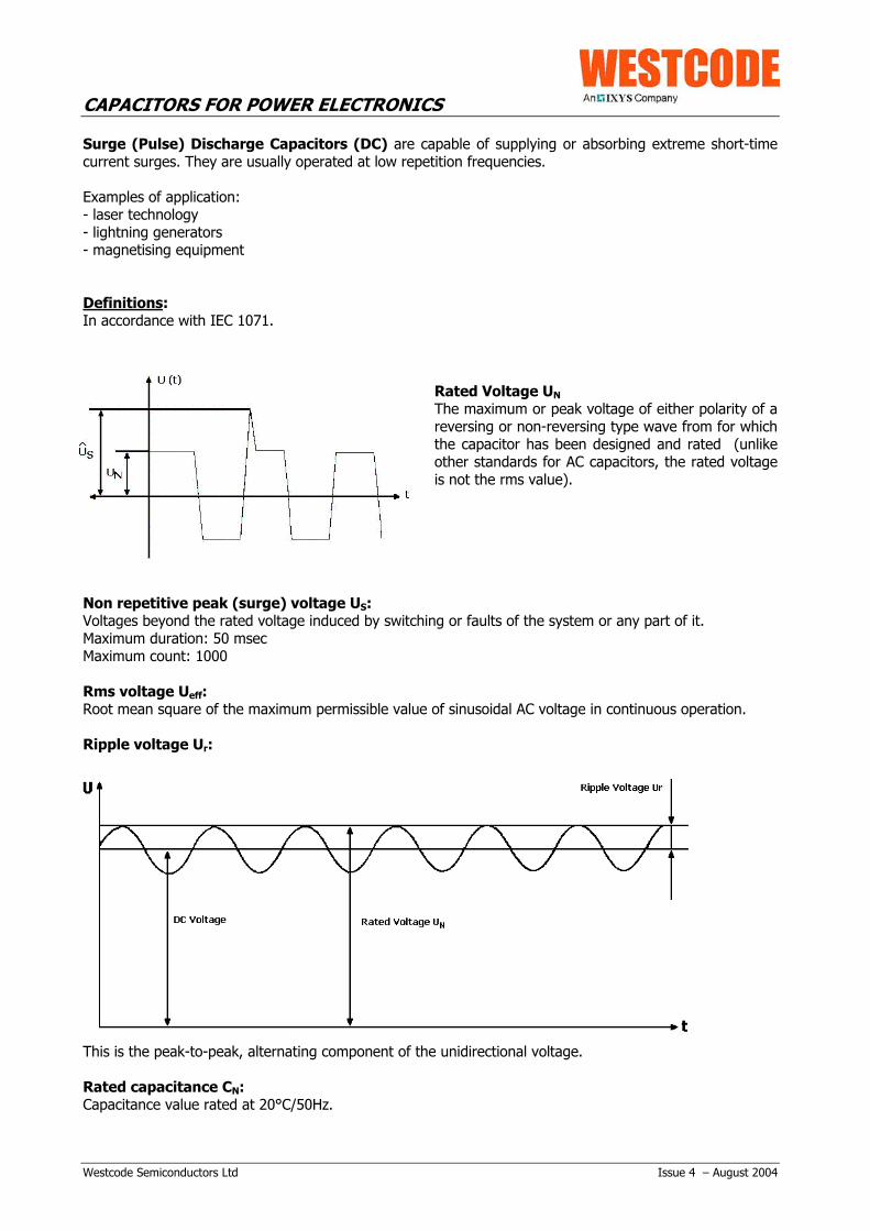
Rated Voltage UN
The maximum or peak voltage of either polarity of areversing or non-reversing type wave from for whichthe capacitor has been designed and rated (unlikeother standards for AC capacitors, the rated voltageis not the rms value).
Non repetitive peak (surge) voltage US:Voltages beyond the rated voltage induced by switching or faults of the system or any part of it.Maximum duration: 50 msecMaximum count: 1000
Rms voltage Ueff:Root mean square of the maximum permissible value of sinusoidal AC voltage in continuous operation.
Ripple voltage Ur:
This is the peak-to-peak, alternating component of the unidirectional voltage.
Rated capacitance CN:Capacitance value rated at 20°C/50Hz.

CAPACITORS FOR POWER ELECTRONICS
Westcode Semiconductors Ltd Issue 4 – August 2004
Maximum current Imax:This is the maximum rms value of permissible current in continuous operation. The values given in thedata sheets are related to either the specified maximum power dissipation or the current limits of theconnection terminals.
Peak current Î:Maximum permitted repetitive current amplitude during continuous operation.
Rate of voltage rise (du/dt)max:Maximum permitted repetitive rate of voltage rise of the operational voltage: î = CN x (du/ dt)max
Non-repetitive peak current (surge) IS:This is the maximum current which may occur non-repetitively, and briefly, in the event of a fault.Maximum duration: 50 msecMaximum count: 1000
Maximum non-repetitive rate of voltage rise (du/dt)s:Peak rate of voltage rise that may non-repetitively and briefly in the event of a fault. IS = CN x (du/dt)s
Series resistance RS:Resistance of the capacitor which determines its heat dissipation (I2
eff x RS).
Dielectric dissipation factor tanδ0:Constant dissipation factor of the dielectric material for all capacitors in their rated frequency.
Maximum power dissipation Pmax:Maximum permitted power dissipation for the capacitor’s operation.
Pmax = ΘHOTSPOT - ΘU Rth
Voltage test between terminals UBB:Routine test of all capacitors conducted at room temperature, prior to delivery. A further test with 80% ofthe test voltage stated in the data sheet may be carried out once at the user’s location.
Voltage test between terminals and case UBG:Routine test of all capacitors between short-circuited terminals and case, conducted at room temperature.May be repeated at the user’s location.
Insulation voltage Ui:Rms value of the AC voltage for which the terminals to case insulation has been designed and tested. Ifnot stated in the data sheets, the insulation voltage is Ui = Un
√2Ambient temperature Θu:Measured 10 cm away and at 2/3 of the case height of the capacitor.
Lower category temperature Θmin:Lower permissible ambient temperature at which a capacitor may be used.
Upper category temperature Θmax:Highest permissible capacitor temperature, i.e. temperature at the hottest point of the case.
Hotspot temperature ΘHOTSPOT:Temperature at the hottest spot inside the capacitor.

CAPACITORS FOR POWER ELECTRONICS
Westcode Semiconductors Ltd Issue 4 – August 2004
Thermal resistance Rth:The thermal resistance indicates by how many degrees the capacitor temperature at the hotspot rises inrelation to the dissipation losses.
Climatic categories:C: maximum relative humidity 95% annual means, 100% occasional condensation permittedF: maximum relative humidity 75% annual means, 95% 30 days/year condensation not permitted
3. Construction of the capacitors
MKP-DielectricThe MKP-type capacitors consist of a low-loss dielectric formedby pure polypropylene film. Thin self-healing metal layers aredeposited directly on one side of the film. In some casesadditional unmetallised foils are added between the metallisedones.
The capacitor elements are dried in a vacuum. After insertioninto the capacitor case, a patented liquid polyurethane resin,mainly containing castor oil, is introduced. This protects thewinding from environmental influence and provides an extendedlife expectancy and stable capacitance.DC capacitors with a rated voltage below 1000V can also bemade totally dry, i.e. without any impregnant.
4. Safety
Protection against Accidental ContactAll capacitors with metal case are checked by 100% routine test (voltage test between terminations andcase) in accordance with IEC 1071. Accessible capacitors must be earthed at the bottom stud or with anadditional earthing clamp. The terminals of the designs L1, L3, M1 and M3 comply with protection degreeIP20. All other capacitors are not protected against accidental contact.
Protection against Overload and Failure at the End of Useful Service LifeAll described dielectric structures are “self-healing”: In the event of a voltage breakdown the metal layersaround the breakdown channel are evaporated by the temperature of the electric arc that forms betweenthe electrodes. They are removed within a few microseconds and pushed apart by the overpressuregenerated in the centre of the breakdown spot. An insulation area is formed which is reliably resistive andvoltage proof for all operating requirements of the capacitor. The capacitor remains fully functional duringand after the breakdown.
In the event of overvoltage or ageing at the end of the capacitor’suseful service life, an increasing number of self-healingbreakdowns may cause rising pressure inside the capacitor. Toprevent it from bursting, the capacitor is fitted with an obligatory“break action mechanism”. This safety mechanism is based on anattenuated spot at one of the connecting wires inside thecapacitor. With rising pressure the casing begins to expand,mainly by opening the folded crimp and pushing the lid upwards.As a result, the prepared connecting wire is separated at theattenuated spot, and the current path is interrupted irreversibly. Ithas to be noted that this safety system can act properly onlywithin the permitted limits of loads and over loads.
CAPACITORS FOR POWER ELECTRONICS
Westcode Semiconductors Ltd Issue 4 – August 2004
The capacitors in rectangular case are provided with an overpressure switch that would signal a risingpressure inside the case. A corresponding external safety circuit, which disconnects the capacitorimmediately in such event, has to be provided by the user.
Protection Against Overvoltages and Short CircuitsAs previously indicated, the capacitors are self-healing and regenerated themselves after breakdowns ofthe dielectric. For voltages within the permitted testing and operating maximum the capacitors areovervoltage-proof. They are also proof against external short circuits as far as the resulting surgedischarges do not exceed the specified current limits (IS).
Permitted Overvoltages according to IEC 10711.1 x UN 30% of the service period1.15 x UN 30 min/d1.2 x UN 5 min/d1.3 x UN 1 min/d1.5 x UN 100ms/d
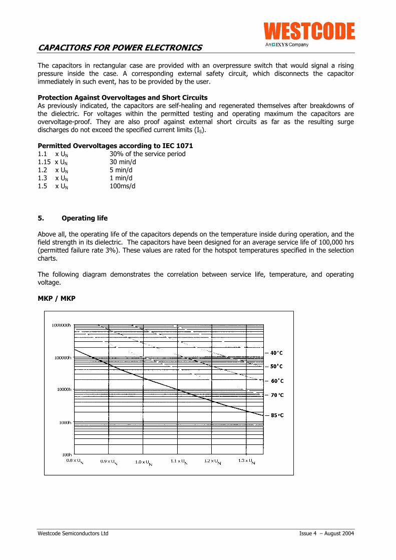
5. Operating life
Above all, the operating life of the capacitors depends on the temperature inside during operation, and thefield strength in its dielectric. The capacitors have been designed for an average service life of 100,000 hrs(permitted failure rate 3%). These values are rated for the hotspot temperatures specified in the selectioncharts.
The following diagram demonstrates the correlation between service life, temperature, and operatingvoltage.
MKP / MKP
CAPACITORS FOR POWER ELECTRONICS
Westcode Semiconductors Ltd Issue 4 – August 2004
6. Mounting and Operating Instructions
ConnectionDo not expose the soldering to excessive heat. It is not recommended to solder cables to the terminals.Use appropriate tab connectors to connect the cables.
Do not bend or turn or move otherwise the connecting terminals and the tab connectors.
Connection at threaded studs shall be made between two nuts. During connection the lower nut shall bebacked up to avoid any transmission of the torque above the a.m. figures to the ceramic body.
Permitted torque for screw connections:
M5: 1.5 NmM6: 2.5 NmM10: 7 NmM12: 10 NmScrew terminal type L (M5): 3 NmScrew terminal type M (M6): 4 Nm
Connection of capacitors with break-action mechanismCapacitors with break-action mechanism shall be connected with sufficiently flexible leads to permit thefunctioning of the mechanism, and sufficient space for expansion of the capacitor case must be left abovethe terminals. Depending on the specific dimensions of the capacitors the case could expand between5mm and 15mm.
- Connect these capacitors only with flexible cables or elastic copper bands.- Do not hold the folded crimps by retaining clamps.- Accommodate a clearance of at least 20mm above the terminations for extension in case of overload.Mind that required clearances must be maintained even after a prolongation of the can (as a result of thebreak action mechanism).
The hermetic sealing of the capacitors is extremely important for a long operating life and for the correctfunctioning of the break action mechanism. Please pay special attention not to damage the followingcritical sealing points at the:
- bordering of the lid- connection between screw terminal and lid- rubber seal at the bottom of the tab connectors- soldering at the bottom of the tab connectors- ceramic insulators
Do not hit the bordering and the connecting terminals with heavy or sharp objects or tools (e.g. hammer,screw driver).
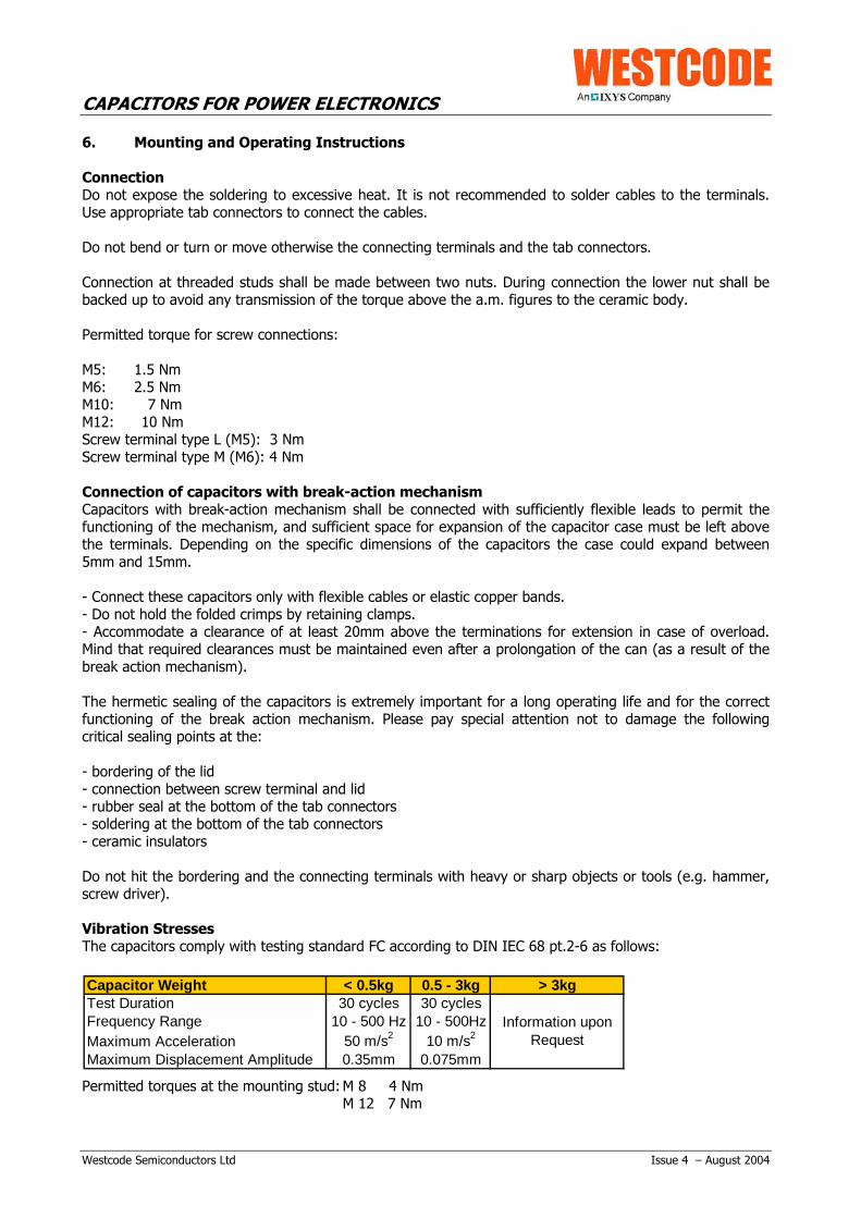
Vibration StressesThe capacitors comply with testing standard FC according to DIN IEC 68 pt.2-6 as follows:
Permitted torques at the mounting stud: M 8 4 NmM 12 7 Nm
Capacitor Weight < 0.5kg 0.5 - 3kg > 3kgTest Duration 30 cycles 30 cyclesFrequency Range 10 - 500 Hz 10 - 500HzMaximum Acceleration 50 m/s2 10 m/s2
Maximum Displacement Amplitude 0.35mm 0.075mm
Information upon Request

CAPACITORS FOR POWER ELECTRONICS
Westcode Semiconductors Ltd Issue 4 – August 2004
Energy content in the event of fireAll capacitors are designed and manufactured in accordance with the relevant international standards.However, for technological requirements it cannot be avoided and must therefore be considered in theapplication that some materials, e.g. the filling resins, oils and winding elements are flammable. Theenergy content of an MKP capacitor is approximately 40 MJ/kg.
Mounting LocationThe useful life of a capacitor may be reduced dramatically if exposed to excessive heat. To avoidoverheating the capacitors must be allowed to emit their heat losses unhindered and shall be shielded fromexternal heat sources. If attenuating circumstances give cause for doubt, special tests should be conductedto ensure that the permitted maximum temperature of the capacitors is not exceeded even under the mostcritical ambient circumstances. It should be noted that the internal heat balance of large capacitors is onlyreached after a couple of hours.
Mounting PositionMKP capacitors with liquid or viscous filling shall be installed upright with terminals facing upwards. Pleasecontact us if a different mounting position is required. Capacitors with hard resin filling can be mounted inany position without restrictions.
EarthingCapacitors with a metal case must be earthed at the mounting stud or by means of a separate metal strapor clamp.
DischargeIf there is no discharge of the capacitors provided by external circuits, the capacitors should be providedwith discharge resistors. In any event, the poles of the capacitors must be short-circuited before beingtouched. Note that the capacitors with nominal voltages above 750V in particular may regenerate newvoltage at their terminals after having been shot-circuited just for short periods. This condition results fromthe internal series connection of the capacitor elements and will be avoided by storing them permanentlyshort-circuited.
DisposalOur capacitors do not contain PCB, solvents or any other toxic or banned materials. The impregnants andfilling materials contain vegetable oil or polyurethane mixtures. The capacitors are not rated as hazardousgoods in transit and do not have to be marked under the Regulations for Hazardous Goods. They arerated WGK 0 (water risk category 0 “no general threat to water”).
Westcode recommend disposing of the capacitors through professional recycling centres forelectric/electronic waste. The capacitors can be disposed of as follows:
- Capacitors: according to European Waste Catalogue (EWC) No. 160216 “Components taken fromdiscarded equipment”
- Liquid filling materials: according to EWC No 080402 “Waste adhesives and sealants free ofhalogenated solvents”
- Hardened filling materials: according to EWC No. 080404 “hardened adhesives and sealants”
Caution: When touching or wasting capacitors with activated break-action mechanism, please considerthat even after days and weeks these capacitors may still be charged with high voltages!

CAPACITORS FOR POWER ELECTRONICS
Westcode Semiconductors Ltd Issue 4 – August 2004
7. Calculation Example
Typically the choice of capacitors for a special application should be as follows:
A capacitor with a capacity of 20µF is needed for a trapezoidal voltage wave form as below:
Choice of the rated voltage:
The rated voltage of the capacitor must be equal to or bigger one of the two voltages U1 and U2. For example; Un > 1000V. Therefore an AC capacitor from the E62 series has to be selected.
Determination of the rate of voltage rise
dU = U1 + U2 = 1500 V = 15 V / µs dt τ 100 µs
Repetitive Peak Current
î = C • (dU / dt) = 15V µs • 20 µF = 300 A
Rated (rms) Current
Ieff = î • √2 • τ • f0 = 46.5 A
Power Dissipation
According to IEC 1071, the power dissipation is determined by the following formula:
PV = PVD + PVR = Û² π • f0 • C tanδ0 + Ieff² • RS
For non-symmetric voltages, û has to be defined as (U1 + U2)/ 2.
In this example, the power dissipation factor is PV = PVD + PVR = 0.84 W + 2.81 W = 3.65 W
The values tanδ0 = 2 x 10⁻⁴ and RS = 1.3 mΩ have been taken from the E62.xxx data charts.
Ambient temperature
By means of the terminal resistance Rth taken from the capacitor chart we can calculate the temperaturedifference between the ambient temperature and the hottest spot inside the capacitor:
∆T = Rth • PV = 5.9 K/W • 3.65 W = 21.5 K
Given a desired service life of ≥100.000 hours, the hotspot temperature must not exceed 70ºC. Thismeans that the maximum ambient temperature for this capacitor is ΘU = ΘHOTSPOT- ∆T = 48ºC

CAPACITORS FOR POWER ELECTRONICS
Westcode Semiconductors Ltd Issue 4 – August 2004
If the calculated power dissipation is too high, the following solutions may be considered:
- reduction of the permitted ambient temperature according to the diagram leading to an increase in thepermitted power dissipation
- connection of a larger number of capacitors with smaller capacitance values (increase of the surfacearea)
- application of capacitors with a rated voltage higher than required by the operating voltage (largerdimensions, greater surface area and power dissipation)
- forced cooling- a reduction of the series resistance by changes to the capacitor’s internal construction

CAPACITORS FOR POWER ELECTRONICS
Westcode Semiconductors Ltd Issue 4 – August 2004
8. List of abbreviations
UN rated voltage
Ums rms voltage at sinusoidal voltage
Ur ripple voltage
US non-repetitive surge voltage
Ui insulation voltage
UBB test voltage between terminals
UBG test voltage between terminals and case
Cn rated capacitance
Wn rated energy content
Imax maximum current (rms value, maximum permissible rated current)
Rs series resistance
Rth thermal resistance
fr resonance frequency
î maximum peak current
Is peak surge current
K creepage distance
L clearance
D1 rated can diameter
L1 rated can length

CAPACITORS FOR POWER ELECTRONICS
Westcode Semiconductors Ltd Issue 4 – August 2004
9. Capacitor Data Tables
MKP AC/DC Capacitors:
9.1 E62.xxx – MKP AC/DC Capacitors
9.2 E62.xxx – Three Phase AC-Filter Capacitors
9.3 E63.xxx – DC Capacitors
9.4 E52.xxx – Low-inductance AC/DC Capacitors in axial design for GTO damping andfor universal use in power electronics
9.5 E53.xxx – Low-inductance AC/DC Capacitors in axial design for general use inpower electronics
9.6 E53.xxx – Low-inductance AC/DC Capacitors in radial design for universal use inpower electronics
9.7 E61.xxx – DC capacitors for direct PCB mounting
9.8 E50.xxx (PK16) – Low-inductance DC capacitors (MKP)
DC Capacitors in Rectangular Case:
9.9 E56.xxx – DC Link capacitors in rectangular case with pressure switch formonitoring of internal pressure.

CAPACITORS FOR POWER ELECTRONICS
Westcode Semiconductors Ltd Issue 4 – August 2004
9.1 E62.xxxMKP- AC/DC – capacitorsAccording to IEC 1071 / VDE 0560 part 120/121
ApplicationUniversal use in power electronics, e.g. ascommutation, supporting, smoothing, surgedischarge capacitors.- filled with liquid resin- integrated overpressure protection (break-actionmechanism)- high specific ratio between capacitance and volume- very good self-healing characteristics- high AC-voltage handling capacity- suitable for high rms and surge currents
General technical dataInternal protection overpressure mechanismtanδ0 2 x 10⁻⁴
operating temperature -40…+85ºCstoring temperature -40…+85ºCcapacitance tolerance ± 5%service life 100,000 h at ΘHOTSPOT ≤70ºC
(permitted failure rate 3%)
UN Urms 300V UBB 1050V DCUs 1050V Ui 1000V UBG 3000V AC
Cn Rs fres Rth Imax Î is D1 L1 weight order no.µF mW kHz K/W A kA kA mm mm drawing kg20 2.5 145 19 16 0.5 1.5 40 58 D1 0.09 E62.E58-203D1W22 4.8 120 16 10 0.3 0.9 35 81 E2 0.1 E62.D81-223E2W24 4.4 115 16 10 0.3 0.9 35 81 E2 0.1 E62.D81-243E2W35 4.4 95 17.3 20 0.4 1.2 40 81 D1 0,11 E62.E81-353D1W50 4.4 80 15.4 20 0.6 1.7 45 81 D1 0,14 E62.F81-503D1W60 2.8 65 13.9 32 0.7 2.1 50 85 G1 0,18 E62.G85-603G1W75 2.6 64 12.6 20 0.75 2.6 55 85 D1 0,21 E62.H85-753D1W80 2.5 63 12.6 20 0.9 2.7 55 85 D1 0,21 E62.H85-803D1W90 2.4 59 11.5 20 1.0 3.0 60 85 D1 0,25 E62.K85-903D1W100 2.2 50 10.1 40 1.2 3.5 65 95 G1 0,3 E62.L95-104G1W120 1.2 39 7.5 50 1.4 4.2 75 105 C2 0,5 E62.M10-124C2W150 1.9 46 8.5 43 1.7 5.1 75 105 L1 0,5 E62.M10-154L1W170 0.9 33 6.6 50 2.0 6.0 85 105 C2 0,6 E62.N10-174C2W180 1.6 36 6.6 43 2.0 6.0 85 105 L1 0,6 E62.N10-184L1W220 0.8 29 5.9 50 2.5 7.5 95 105 C3 0,8 E62.P10-224C3W470 0.6 18 3.5 50 5.3 16 95 176 C3 1,3 E62.P17-474C3W500 0.6 18 3.3 80 5.7 17 100 176 C3 1,5 E62.Q17-504C3W700 0.7 17 2.9 80 8.0 20* 116 176 M1 2,0 E62.R17-704M1W1100 0.5 13 2.1 80 13 20* 116 245 M1 2,7 E62.R24-115M1W1500 0.5 11 1.8 80 15* 20* 136 245 M1 3,7 E62.S24-155M1W2000 0.5 8 1.4 100 15* 20* 136 320 C3 4,9 E62.S32-205C3W
UN Urms 360V UBB 1260V DCUs 1250V Ui 1000V UBG 3000V AC
Cn Rs fres Rth Imax Î is D1 L1 weight order no.µF mW kHz K/W A kA kA mm mm drawing kg1 18 650 37 6 0.1 0.3 25 48 E1 0.06 E62.B48-102E1W25 4.9 113 17.3 20 0.4 1.1 40 81 D1 0,11 E62.E81-253D1W33 4.9 98 15.4 20 0.5 1.4 45 81 D1 0,14 E62.F81-333D1W40 3.2 80 13.9 30 0.6 1.7 50 85 G1 0,18 E62.G85-403G1W50 4.1 80 12.6 20 0.7 2.1 55 85 D1 0,21 E62.H85-503D1W60 3.8 73 11.5 20 0.8 2.5 60 85 D1 0,25 E62.K85-603D1W75 2.3 58 10.1 40 1.0 3.0 65 95 G1 0,3 E62.L95-753G1W100 2.6 48 7.5 43 1.4 4.2 75 105 L1 0,5 E62.M10-104L1W160 1.5 38 5.9 43 2.2 6.6 95 105 L1 0,8 E62.P10-164L1W200 2.7 31 4.5 43 2.8 8.4 75 176 L1 0,8 E62.M17-204L1W300 0.6 23 2.7 80 4.1 12.0 95 176 C3 1.50 E62.P17-304C3W300 0.9 25 3.5 80 4.1 12 95 176 M1 1,3 E62.P17-304M1W350 0.8 24 3.3 80 4.8 14 100 176 M1 1,5 E62.Q17-354M1W500 0.8 20 2.9 80 6.9 20* 116 176 M1 2,0 E62.R17-504M1W620 0.7 16 1.6 100 9.0 15.0 116 245 C3 3.20 E62.R24-624C3W750 0.6 14 2.1 100 10 20* 116 245 C3 2,7 E62.R24-754C3W1000 0.6 12 1.8 100 14 20* 136 245 C3 3,7 E62.S24-105C3W1500 0.5 9 1.4 100 15* 20* 136 320 C3 4,9 E62.S32-155C3W
700V DC - 420V AC
840V DC - 500V AC

CAPACITORS FOR POWER ELECTRONICS
Westcode Semiconductors Ltd Issue 4 – August 2004
UN Urms 450V UBB 1500V DCUs 1500V Ui 1000V UBG 3000V AC
Cn Rs fres Rth Imax Î is D1 L1 weight order no.µF mW kHz K/W A kA kA mm mm drawing kg5 4.9 290 26 10 0.26 0.8 30 58 E1 0.06 E62.C58-502E1W
6.8 4 250 22 16 0.35 1 35 58 E2 0.07 E62.D58-682E2W10 3.1 210 19 20 0.40 1.2 40 58 D1 0.08 E62.E58-103D1W15 5 150 14 20 0.24 0.7 40 81 D1 0.11 E62.E81-153D1W18 5.6 133 14 20 0.29 0.9 40 81 D1 0,11 E62.E81-183D1W22 3.9 120 12 20 0.35 1.1 45 81 D1 0.14 E62.F81-223D1W25 3.6 113 12 20 0.4 1.2 45 81 D1 0,14 E62.F81-253D1W30 3.5 92 10 33 0.5 1.4 50 85 G1 0,18 E62.G85-303G1W40 4.2 89 10 20 0.6 1.9 55 85 D1 0,21 E62.H85-403D1W47 3.9 82 8.7 20 0.8 2.3 60 85 D1 0,25 E62.K85-473D1W50 2.6 71 7.2 40 0.8 2.4 65 95 G1 0,3 E62.L95-503G1W75 2.7 55 5.7 43 1.2 3.6 75 105 L1 0,5 E62.M10-753L1W80 1.9 54 5.0 43 1.3 3.8 85 105 L1 0,6 E62.N10-803L1W120 1.6 44 4.5 43 1.9 5.8 95 105 L1 0,8 E62.P10-124L1W200 0.8 28 2.7 80 3.5 10.5 95 176 C3 1.50 E62.P17-204C3W250 0.7 25 2.5 80 4.0 12 100 176 C3 1,5 E62.Q17-254C3W250 1.9 28 2.7 43 4.0 12 95 176 L1 1,3 E62.P17-254L1W350 0.6 21 2.2 80 5.6 17 116 176 C3 2,0 E62.R17-354C3W500 0.6 17 1.6 100 8.0 20* 116 245 C3 2,7 E62.R24-504C3W800 0.6 14 1.3 100 13 20* 136 245 C3 3,7 E62.S24-804C3W1000 0.6 12 1.0 100 15 20* 136 320 C3 4,9 E62.S32-105C3W
UN Urms 480V UBB 1680V DCUs 1500V Ui 1000V UBG 3000V AC
Cn Rs fres Rth Imax Î is D1 L1 weight order no.µF mW kHz K/W A kA kA mm mm drawing kg12 6.8 162 17.3 18 0.2 0.7 40 81 D1 0,11 E62.E81-123D1W20 5.5 126 15.4 20 0.4 1.1 45 81 D1 0,14 E62.F81-203D1W25 3.6 101 13.9 28 0.5 1.4 50 85 G1 0,18 E62.G85-253G1W30 4.5 103 12.6 20 0.5 1.6 55 85 D1 0,21 E62.H85-303D1W33 4.3 98 11.5 20 0.6 1.8 60 85 D1 0,25 E62.K85-333D1W40 2.8 80 10.1 38 0.7 2.2 65 95 G1 0,3 E62.L95-403G1W60 2.8 62 7.5 43 1.1 3.3 75 105 L1 0,5 E62.M10-603L1W68 1.9 58 6.6 43 1.2 3.7 85 105 L1 0,6 E62.N10-683L1W100 1.6 48 5.6 43 1.8 5.5 100 105 L1 0,9 E62.Q10-104L1W180 1.9 33 3.5 43 3.3 9.9 95 176 L1 1,3 E62.P17-184L1W200 0.7 28 3.3 80 3.7 11 100 176 C3 1,5 E62.Q17-204C3W280 0.6 24 2.9 80 5.1 15 116 176 C3 2,0 E62.R17-284C3W400 0.6 19 2.1 100 7.3 20 116 245 C3 2,7 E62.R24-404C3W600 0.6 16 1.8 100 11 20* 136 245 C3 3,7 E62.S24-604C3W800 0.6 13 1.4 100 15 20* 136 320 C3 4,9 E62.S32-804C3W
UN Urms 530V UBB 1890V DCUs 1900V Ui 1000V UBG 3000V AC
Cn Rs fres Rth Imax Î is D1 L1 weight order no.µF mW kHz K/W A kA kA mm mm drawing kg10 6 152 13.8 16 0.45 1.35 40 81 D1 0.16 E62.E81-103D1W15 7.4 124 15.4 16 0.3 0.9 45 85 B1 0,14 E62.F85-153B1W20 3.9 113 13.9 27 0.4 1.2 50 85 G1 0,18 E62.G85-203G1W24 6.0 98 12.6 16 0.5 1.5 55 85 B1 0,21 E62.H85-243B1W28 5.7 91 11.5 16 0.6 1.7 60 85 B1 0,25 E62.K85-283B1W33 2.9 88 10 37 0.7 2.0 65 95 G1 0,3 E62.L95-333G1W47 3.0 70 7.5 43 1.0 2.9 75 105 L1 0,5 E62.M10-473L1W60 1.9 62 6.6 43 1.2 3.7 85 105 L1 0,6 E62.N10-603L1W75 1.7 55 5.9 43 1.5 4.6 95 105 L1 0,8 E62.P10-753L1W150 2.0 36 3.5 43 3.1 9.3 95 176 L1 1,3 E62.P17-154L1W220 0.7 27 2.9 80 4.5 14 116 176 C3 2,0 E62.R17-224C3W330 0.6 21 2.1 100 6.8 20 116 245 C3 2,7 E62.R24-334C3W500 0.6 17 1.8 100 10 20* 136 245 C3 3,7 E62.S24-504C3W600 0.6 15 1.4 100 12 20* 136 320 C3 4,9 E62.S32-604C3W
1000V DC - 640V AC
1120V DC - 680V AC
1260V DC - 750V AC

CAPACITORS FOR POWER ELECTRONICS
Westcode Semiconductors Ltd Issue 4 – August 2004
UN Urms 600V UBB 2100V DCUs 2100V Ui 1000V UBG 3000V AC
Cn Rs fres Rth Imax Î is D1 L1 weight order no.µF mW kHz K/W A kA kA mm mm drawing kg2 7.6 460 26 10 0.18 0.5 30 58 E11) / E4 0.07 E62.C58-202E1W
2.2 7 440 26 10 0.2 0.6 30 58 E11) / E4 0.07 E62.C58-222E1W4 10 280 18 10 0.18 0.5 30 81 E11) / E4 0.08 E62.C81-402E1W12 7.9 139 12 16 0.3 0.8 45 85 B1 0.14 E62.F85-123B1W16 4.2 126 10 30 0.4 1.1 50 85 G1 0.18 E62.G85-163G1W25 3.2 101 7.2 40 0.6 1.7 65 95 G1 0.3 E62.L95-253G1W33 3.3 84 5.7 38 0.8 2.3 75 105 L1 0.5 E62.M10-333L1W47 2.1 70 5.0 43 1.1 3.2 85 105 L1 0.6 E62.N10-473L1W60 1.8 62 4.5 43 1.4 4.1 95 105 L1 0.8 E62.P10-603L1W120 0.8 36 2.7 80 2.7 8.2 95 176 C3 1.3 E62.P17-124C3W130 0.8 35 2.5 80 3.0 8.9 100 176 C3 1.5 E62.Q17-134C3W180 0.7 30 2.2 80 4.1 12 116 176 C3 2.0 E62.R17-184C3W270 0.7 23 1.6 100 6.2 19 116 245 C3 2.7 E62.R24-274C3W400 0.605 19 1.3 100 9.2 20* 136 245 C3 3.7 E62.S24-404C3W500 0.6 16 1.0 100 11.4 20* 136 320 C3 4.9 E62.S32-504C3W
1) UNDC limited to 1200V
UN Urms 720V UBB 2520V DCUs 2500V Ui 1250V UBG 3500V AC
Cn Rs fres Rth Imax Î is D1 L1 weight order no.µF mW kHz K/W A kA kA mm mm drawing kg1.5 5.3 530 26 10 0.3 0.9 30 58 E11) / E4 0.07 E62.C58-152E..W3 6.9 320 18 10 0.35 1.05 30 81 E11) / E4 0.08 E62.C81-302E..W4 5.6 280 16 10 0.45 1.35 35 81 E2 1) 0.09 E62.D81-402E2W5 4.8 250 14 20 0.6 1.8 40 81 D1 1) 0.12 E62.E81-502D1W
6.8 3.9 220 12 20 0.8 2.4 45 81 D1 1) 0.14 E62.F81-682D1W8 4.4 170 12 16 0.5 1.4 45 85 B1 0.14 E62.F85-802B1W10 3.8 159 10 32 0.6 1.7 50 85 G1 0.18 E62.G85-103G1W12 5.9 139 10 16 0.7 2.1 55 85 B1 0.21 E62.H85-123B1W15 5.5 124 8.7 16 0.9 2.6 60 85 D1 1) 0.25 E62.K85-153D1W16 3.6 120 7.2 40 0.95 2.9 65 95 G1 0.3 E62.L95-163G1W18 2.7 119 7.2 40 1.0 3.1 65 95 G1 0.3 E62.L95-183G1W20 1.7 95 5.7 50 1.2 3.5 75 105 C2 0.5 E62.M10-203C2W28 1.3 80 5.0 50 1.6 4.9 85 105 C2 0.6 E62.N10-283C2W33 1.1 74 4.5 50 1.9 5.7 95 105 C3 0.8 E62.P10-333C3W68 0.8 48 2.7 80 3.9 12 95 176 C3 1.3 E62.P17-683C3W80 0.7 44 2.5 80 4.6 14 100 176 C3 1.5 E62.Q17-803C3W120 0.6 36 2.2 80 7.0 20 116 176 C3 2.0 E62.R17-124C3W180 0.6 29 1.6 100 10.4 20* 116 245 C3 2.7 E62.R24-184C3W220 0.7 25 1.2 100 14.0 20.0 116 320 C3 4.1 E62.R32-224C3W250 0.6 24 1.3 100 14.5 20* 136 245 C3 3.7 E62.S24-254C3W330 0.6 20 1.0 100 15* 20* 136 320 C3 4.9 E62.S32-334C3W
1) UNDC limited to 1200V
UN Urms 850V UBB 2100V DCUs 2000V Ui 1000V UBG 3000V AC
Cn Rs fres Rth Imax Î is D1 L1 weight order no.µF mW kHz K/W A kA kA mm mm drawing kg0.1 21 2050 31 8 0.10 0.3 25 58 E1 0.05 E62.B58-101E1W0.15 14 1678 26 8 0.10 0.3 30 58 E1 0.06 E62.C58-151E1W0.22 10 1390 26 10 0.20 0.6 30 58 E1 0.05 E62.C58-221E1W0.33 9 1130 26 10 0.20 0.6 30 58 E1 0.05 E62.C58-331E1W0.47 9 950 26 10 0.20 0.6 30 58 E1 0.05 E62.C58-471E1W0.5 8.5 919 26 10 0.16 0.48 30 58 E1 0.05 E62.C58-501E1W0.68 7.2 790 26 10 0.22 0.7 30 58 E1 0.05 E62.C58-681E1W
1 6.5 650 26 10 0.25 0.8 30 58 E1 0.05 E62.C58-102E1W2 7.7 459 26 15 0.3 0.9 30 58 E1 0.06 E62.C58-202E1W
2.2 10 360 16 10 0.2 0.6 30 93 E1 0.08 E62.C93-222E1W4 5 280 14 20 0.3 0.9 40 81 D1 0.12 E62.E81-402D1W5 4.3 250 12 20 0.35 1.1 45 81 D1 0.14 E62.F81-502D1W
6.8 3.6 220 10 20 0.5 1.5 50 85 D1 0.18 E62.G85-682D1W10 3.0 180 8.7 20 0.7 2.1 60 85 D1 0.25 E62.K85-103D1W22 4.9 110 4.9 20 1.2 3.6 60 151 D1 0.4 E62.K15-223D1W30 4.3 80 4.3 20 1.0 3 65 160 D2 0.6 E62.L16-303D2W
1400V DC - 850V AC
1680V DC - 1000V AC
1200V AC

CAPACITORS FOR POWER ELECTRONICS
Westcode Semiconductors Ltd Issue 4 – August 2004
UN Urms 850V UBB 3000V DCUs 2000V Ui 1500V UBG 4000V AC
Cn Rs fres Rth Imax Î is D1 L1 weight order no.µF mW kHz K/W A kA kA mm mm drawing kg1 6.5 650 26 10 0.25 0.8 30 58 E4 0.07 E62.C58-102E4W
2.2 10 360 16 10 0.2 0.6 30 93 E4 0.08 E62.C93-222E4W6.8 3.6 190 10.5 33 0.5 1.5 50 85 G1 0.18 E62.G85-682G1W10 3.3 160 7.2 40 0.7 2.1 65 95 G1 0.33 E62.L95-103G1W15 3.8 120 6.3 40 0.8 2.4 65 109 G1 0.38 E62.L10-153G1W30 4.3 80 4.3 40 1.0 3 65 160 G1 0.6 E62.L16-303G1W40 0.8 63 3.0 80 2.7 8.1 85 176 C2 1.2 E62.N17-403C2W100 1.8 41 2.2 80 3.2 9.6 116 176 C4 2.1 E62.R17-104C4W
UN Urms 960V UBB 3375V DCUs 3300V Ui 1600V UBG 4200V AC
Cn Rs fres Rth Imax Î is D1 L1 weight order no.µF mW kHz K/W A kA kA mm mm drawing kg4 5.5 230 10.5 26 0.32 0.96 50 85 G1 0.18 E62.G85-402G1W5 5.1 225 13.9 25 0.4 1.2 50 85 G1 0.18 E62.G85-502G1W
6.8 6.6 184 12.6 16 0.5 1.6 55 85 B1 0.21 E62.H85-682B1W10 2.3 135 7.5 45 0.8 2.3 75 105 C2 0.5 E62.M10-103C2W15 1.1 119 5.0 50 1.1 3.3 85 105 C2 0.8 E62.N10-153C2W16 1.6 106 6.6 50 1.2 3.7 85 105 C2 0.6 E62.N10-163C2W20 1.3 95 5.9 50 1.5 4.6 95 105 C3 0.8 E62.P10-203C3W40 0.9 63 3.5 80 3.1 9.3 95 176 C3 1.3 E62.P17-403C3W47 0.8 58 3.3 80 3.6 11 100 176 C3 1.5 E62.Q17-473C3W68 0.7 48 2.9 80 5.3 16 116 176 C3 2.0 E62.R17-683C3W100 0.7 39 2.1 100 7.7 20* 116 245 C3 2.7 E62.R24-104C3W150 0.6 32 1.8 100 11.6 20* 136 245 C3 3.7 E62.S24-154C3W200 0.6 26 1.4 100 15* 20* 136 320 C3 4.9 E62.S32-204C3W
UN Urms 1200V UBB 4200V DCUs 4200V Ui 2000V UBG 5000V AC
Cn Rs fres Rth Imax Î is D1 L1 weight order no.µF mW kHz K/W A kA kA mm mm drawing kg
0.33 9 1130 26 10 0.2 0.6 30 58 E4 0.07 E62.C58-331E4W0.47 9 950 26 10 0.2 0.6 30 58 E4 0.07 E62.C58-471E4W
1 11 560 18 10 0.2 0.6 30 81 E4 0.08 E62.C81-102E4W2.5 10.2 291 15 16 0.2 0.7 45 85 B2 0.14 E62.F85-252B2W3.3 8.8 253 14 16 0.3 1.0 50 85 B2 0.17 E62.G85-332B2W4.7 7.4 212 13 16 0.5 1.4 55 85 B2 0.21 E62.H85-472B2W6.8 2.6 163 7.5 46 0.7 2.0 75 105 C2 0.5 E62.M10-682C2W10 1.9 135 6.6 50 1.0 2.9 85 105 C2 0.6 E62.N10-103C2W12 1.6 123 5.9 50 1.2 3.5 95 105 C3 0.8 E62.P10-123C3W25 1.0 80 3.5 80 2.4 7.3 95 176 C3 1.3 E62.P17-253C3W30 0.9 73 3.3 80 2.9 8.7 100 176 C3 1.5 E62.Q17-303C3W40 0.8 63 2.9 80 3.9 12 116 176 C3 2.0 E62.R17-403C3W50 1.5 58 2.2 80 2.3 7 116 176 C4 2.1 E62.R17-503C4W60 0.7 50 2.1 100 5.8 17 116 245 C3 2.7 E62.R24-603C3W90 0.6 41 1.8 100 8.7 20* 136 245 C3 3.7 E62.S24-903C3W125 0.6 33 1.4 100 12.1 20* 136 320 C3 4.9 E62.S32-134C3W
UN Urms 1400V UBB 5100V DCUs 4200V Ui 2400V UBG 5800V AC
Cn Rs fres Rth Imax Î is D1 L1 weight order no.µF mW kHz K/W A kA kA mm mm drawing kg10 2.6 122 4.5 40 1.2 3.5 75 176 C2 0.8 E62.M17-103C2W15 2.2 100 3.5 40 1.0 3.1 95 176 C3 1.3 E62.P17-153C3W20 1.2 89 3.3 50 2.3 7.0 100 176 C3 1.5 E62.Q17-203C3W30 1.0 73 2.9 50 3.6 11 116 176 C3 2.0 E62.R17-303C3W40 1.2 58 1.2 80 4.6 14 116 320 C3 4.1 E62.R32-403C3W60 1.2 48 1.6 100 6.0 18 116 320 C3 3.5 E62.R32-603C3W90 1.1 38 1.4 100 9.7 20* 136 320 C3 4.9 E62.S32-903C3W
2000V DC 1200V AC
2250V DC - 1350V AC
2800V DC - 1700V AC
3400V DC - 2000V AC

CAPACITORS FOR POWER ELECTRONICS
Westcode Semiconductors Ltd Issue 4 – August 2004
UN Urms 1500V UBB 5400V DCUs 5400V Ui 2600V UBG 6200V AC
Cn Rs fres Rth Imax Î is D1 L1 weight order no.µF mW kHz K/W A kA kA mm mm drawing kg0.1 21 2050 26 9 0.10 0.3 30 58 E4 0.07 E62.C58-101E4W0.22 10 1390 26 10 0.20 0.6 30 58 E4 0.07 E62.C58-221E4W0.47 6.7 730 16 16 0.40 1.2 45 62 B2 0.10 E62.F62-471B2W0.68 5.6 610 14 16 0.5 1.5 50 62 B2 0.13 E62.G62-681B2W
1 8.5 460 9.4 16 0.8 2.4 45 105 B2 0.18 E62.F10-102B2W1.5 5.4 380 7.7 16 1.2 3.6 55 105 B2 0.26 E62.H10-152B2W22 1.7 90 2.2 50 1.2 3.5 116 176 CR 2.0 E62.R17-223CRW33 1.1 72 1.9 80 3.3 9.9 116 205 C3 2.4 E62.R20-333C3W40 0.8 60 1.2 100 5.4 16 116 320 CR 3.5 E62.R32-403CRW
UN Urms 1700V UBB 6000V DCUs 6000V Ui 2900V UBG 6800V AC
Cn Rs fres Rth Imax Î is D1 L1 weight order no.µF mW kHz K/W A kA kA mm mm drawing kg2 5.6 325 8.5 16 0.5 1.5 50 105 B2 0.24 E62.G10-202B2W4 9 183 5.3 16 0.6 1.8 55 151 B2 0.4 E62.H15-402B2W
6.8 2.4 153 4.5 40 0.9 2.8 75 176 C2 0.8 E62.M17-682C2W10 1.8 122 3.0 40 1.4 4.2 85 176 C2 1.0 E62.N17-103C2W22 1.1 90 2.9 50 3.0 9.0 116 176 CR 2.0 E62.R17-223CRW
UN Urms 2800V UBB 7500V DCUs 7500V Ui 3600V UBG 8200V AC
Cn Rs fres Rth Imax Î is D1 L1 weight order no.µF mW kHz K/W A kA kA mm mm drawing kg0.1 5.7 1590 12.2 16 0.40 1.2 45 81 B2 0.14 E62.F81-101B2W0.47 9.1 670 9.4 16 0.37 1.1 45 105 B2 0.18 E62.F10-471B2W0.68 7.4 560 7.7 16 0.50 1.5 55 105 B2 0.26 E62.H10-681B2W
1 3.0 410 5.0 40 0.8 2.4 75 120 C2 0.6 E62.M12-102C2W2.2 1.6 280 3.9 40 1.7 5 95 120 CR 0.9 E62.P12-222CRW4.7 1.0 180 2.2 40 3.7 11 95 210 CR 1.6 E62.P21-472CRW10 2.6 120 1.4 50 6.0 18 116 280 CR 3.1 E62.R28-103CRW
3600V DC - 2100V AC
4000V DC - 2400V AC
5000V DC - 4000V AC

CAPACITORS FOR POWER ELECTRONICS
Westcode Semiconductors Ltd Issue 4 – August 2004
9.2 E62.xxxThree-phase AC- Filter capacitorsAccording to IEC 1071 / EN 61071 and IEC 831 / EN 60831
Application:
Filtering / power factor correction in three phase mains
- filled with liquid PUR resin- very low series resistance- low self-inductance- very good self-healing characteristics- high surge voltage strength- design L/M: finger-proof terminals (IP20)
General technical dataInternal protection overpressure mechanismtanδ0 2 x 10⁻⁴
operating temperature -40…+70ºCstoring temperature -40…+70ºCcapacitance tolerance ± 5%service life 100,000 h at ΘHOTSPOT ≤ 60ºC
(permitted failure rate 3%)
UN 640V AC Urms 450V UBB 970V 50Hz AC / 2sUs 1500V UBG 3600V 50Hz AC / 2s
Cn Rs fres Rth Imax Î is D1 L1 drawing weight order no.µF mW kHz K/W A kA kA mm mm kg
3x 14 3x 2.0 130 5.9 3x 16 0.4 2 50 151 D3 0.3 E62.G15-143D3W3x 17 3x 1.8 120 5.9 3x 16 0.5 2 50 151 D3 0.3 E62.G15-173D3W3x 24 3x 1.7 100 4.9 3x 16 0.7 3 60 151 D3 0.4 E62.K15-243D3W3x 33 3x 1.2 90 3.6 3x 43 0.9 5 75 164 L3 0.8 E62.M16-333L3W3x 40 3x 1.2 70 3.6 3x 43 1.1 6 75 164 L3 0.8 E62.M16-403L3W3x 46 3x 1.1 70 3.2 3x 43 1.3 6 85 164 L3 1.0 E62.N16-463L3W3x 51 3x 1.1 60 3.2 3x 43 1.4 7 85 164 L3 1.0 E62.N16-513L3W3x 57 3x 0.8 60 2.9 3x 43 1.6 8 95 164 L3 1.2 E62.P16-573L3W3x 68 3x 0.8 60 2.9 3x 43 2.0 10 95 164 L3 1.2 E62.P16-683L3W3x 100 3x 0.6 50 2.3 3x 43 3.0 15 116 164 L3 2.1 E62.R16-104L3W
UN 1080V AC Urms 760V UBB 1635V 50Hz AC / 2sUs 2300V UBG 4800V 50Hz AC / 2s
Cn Rs fres Rth Imax Î is D1 L1 drawing weight order no.µF mW kHz K/W A kA kA mm mm kg
3x 4.7 3x 1.8 230 5.9 3x 16 0.5 3 50 151 D3 0.3 E62.G15-472D3W3x 5.0 3x 1.8 230 5.4 3x 16 0.5 3 55 151 D3 0.3 E62.H15-502D3W3x 7.3 3x 1.7 190 4.9 3x 16 0.8 4 60 151 D3 0.4 E62.K15-732D3W3x 9.7 3x 1.2 150 3.6 3x 43 1.1 5 75 164 L3 0.8 E62.M16-972L3W3x 11.0 3x 0.9 140 3.2 3x 43 1.2 6 85 164 L3 1.0 E62.N16-113L3W3x 18.4 3x 0.8 110 2.9 3x 43 2.0 10 95 164 L3 1.2 E62.L95-403G1W3x 22.0 3x 0.8 100 2.7 3x 43 2.4 12 100 164 L3 1.5 E62.P16-223L3W3x 27.6 3x 0.6 90 2.3 3x 43 3.0 15 116 164 L3 2.1 E62.R16-283L3W

CAPACITORS FOR POWER ELECTRONICS
Westcode Semiconductors Ltd Issue 4 – August 2004
9.3 E63.xxxDC capacitorsAccording to IEC 1071 / VDE 0560 part 120/121
ApplicationSmoothing capacitors, supporting capacitors in buffer storage circuits.
- filled with liquid resin- integrated overpressure protection (break-action mechanism)- very good ratio between capacitance and volume- very good self-healing characteristics and high overvoltage proofness- suitable for high rms currents
General technical dataInternal protection overpressure mechanismtanδ0 2 x 10⁻⁴
operating temperature -25…+70ºCstoring temperature -40…+85ºCcapacitance tolerance ± 10%service life 100,000 h at ΘHOTSPOT ≤ 65ºC
(permitted failure rate 3%)
UN 800V DC Uripple 200V UBB 1200V DCUs 1200V Ui 1000V UBG 3000V AC
Cn Rs fres Rth Imax Î is D1 L1 drawing weight order no.µF mW kHz K/W A kA kA mm mm kg100 3.3 50 13.5 28 0.9 2.8 50 85 G1 0.18 E63.G85-104G1W175 2.3 38 9.8 30 1.6 4.8 65 95 G1 0.31 E63.L95-184G1W250 2.1 28 6.4 43 2.3 6.9 85 105 L1 0.63 E63.N10-254L1W680 1.9 17 3.4 43 6.2 19 95 176 L1 1.3 E63.P17-684L1W800 1.8 16 3.3 43 7.3 20 100 176 L1 1.5 E63.Q17-804L1W
UN 1000V DC Uripple 200V UBB 1500V DCUs 1500V Ui 1000V UBG 3000V AC
Cn Rs fres Rth Imax Î is D1 L1 drawing weight order no.µF mW kHz K/W A kA kA mm mm kg60 3.6 65 13.5 25 0.7 2.1 50 85 G1 0.18 E63.G85-603G1W80 4.6 63 12.3 20 0.9 2.8 55 85 D2 0.21 E63.H85-803D2W100 4.2 50 9.8 28 1.1 3.4 65 95 G1 0.31 E63.L95-104G1W150 2.3 36 7.3 43 1.7 5.2 75 105 L1 0.5 E63.M10-154L1W250 2.1 28 5.7 43 2.9 8.6 95 105 L1 0.8 E63.P10-254L1W470 2.0 20 3.4 43 5.4 16.1 95 176 L1 1.3 E63.P17-474L1W700 1.0 17 2.8 80 8.0 20 116 176 M1 2.0 E63.R17-704M1W1000 0.75 12 2.0 80 11 20 * 116 245 C3 2.7 E63.R24-105C3W1200 0.65 9 2.0 80 9 16 116 245 C3 2.7 E63.R24-125C3W1500 0.6 10 1.7 80 15* 20 * 136 245 C3 3.7 E63.S24-155C3W1800 0.6 8.6 1.3 100 15* 20 * 136 320 C3 4.9 E63.S32-185C3W
UN 1200V DC Uripple 280V UBB 1800V DCUs 1800V Ui 1000V UBG 3000V AC
Cn Rs fres Rth Imax Î is D1 L1 drawing weight order no.µF mW kHz K/W A kA kA mm mm kg40 5 80 13.5 22 0.6 1.7 50 85 G1 0.18 E63.G85-403G1W50 6.3 68 12.3 16 0.7 2.1 55 85 B1 0.21 E63.H85-503B1W75 3.5 58 9.8 32 1.0 3.1 65 95 G1 0.3 E63.L95-753G1W100 1.5 43 6.4 43 1.4 4.1 85 105 L1 0.6 E63.N10-104L1W160 1.3 34 5.7 43 2.2 6.6 95 105 L1 0.8 E63.P10-164L1W300 0.9 23 3.4 43 4.1 12.4 95 176 L1 1.3 E63.P17-304L1W500 0.7 18 2.8 80 6.9 20 * 116 176 M1 2.0 E63.R17-504M1W750 0.7 14 2.0 80 10.3 20 * 116 245 C3 2.7 E63.R24-754C3W1000 0.65 12 1.7 100 13.7 20 * 136 245 C3 3.7 E63.S24-105C3W

CAPACITORS FOR POWER ELECTRONICS
Westcode Semiconductors Ltd Issue 4 – August 2004
UN 1400V DC Uripple 350V UBB 2100V DCUs 2100V Ui 1000V UBG 3000V AC
Cn Rs fres Rth Imax Î is D1 L1 drawing weight order no.µF mW kHz K/W A kA kA mm mm kg30 6 92 13.5 20 0.5 1.4 50 85 G1 0.18 E63.G85-303G1W40 6.6 76 12.3 16 0.6 1.9 55 85 B1 0.21 E63.H85-403B1W50 4.1 71 9.8 28 0.8 2.4 65 95 G1 0.31 E63.L95-503G1W80 1.9 48 6.4 43 1.3 3.8 85 105 L1 0.6 E63.N10-803L1W110 1.5 41 5.7 43 1.8 5.3 95 105 L1 0.8 E63.P10-114L1W220 1 27 3.4 43 3.5 10.6 95 176 L1 1.3 E63.P17-224L1W250 0.95 25 3.3 43 4.0 12.0 100 176 L1 1.5 E63.Q17-254L1W350 0.8 21 2.8 80 5.6 16.8 116 176 M1 2.0 E63.R17-354M1W500 0.75 17 2.0 80 8.0 20 * 116 245 M1 2.7 E63.R24-504M1W800 0.65 14 1.7 100 12.8 20 * 136 245 C3 3.7 E63.S24-804C3W1000 0.7 12 1.4 100 15.0 20 * 136 320 C3 3.9 E63.S32-954C3W
UN 1600V DC Uripple 400V UBB 2400V DCUs 2400V Ui 1200V UBG 3400V AC
Cn Rs fres Rth Imax Î is D1 L1 drawing weight order no.µF mW kHz K/W A kA kA mm mm kg
25 6 101 13.5 20 0.5 1.4 50 85 G1 0.18 E63.G85-253G1W40 4.5 80 9.8 28 0.7 2.2 65 95 G1 0.31 E63.L95-403G1W47 2.7 62 7.3 40 0.9 2.6 75 105 C2 0.5 E63.M10-473C2W68 2 52 6.4 40 1.3 3.8 85 105 C2 0.6 E63.N10-683C2W
110 1.4 38 3.8 80 2.0 6.0 85 176 C2 1.0 E63.N17-114C2W200 1 28 3.3 80 3.7 11.0 100 176 C3 1.5 E63.Q17-204C3W280 0.8 24 2.8 80 5.1 15.4 116 176 C3 2.0 E63.R17-284C3W400 0.75 19 2.0 100 7.3 20 * 116 245 C3 2.7 E63.R24-404C3W
UN 1800V DC Uripple 400V UBB 2700V DCUs 2700V Ui 1300V UBG 3600V ACCn Rs fres Rth Imax Î is D1 L1 drawing weight order no.µF mW kHz K/W A kA kA mm mm kg20 6.5 113 13.5 20 0.4 1.2 50 85 G1 0.18 E63.G85-203G1W33 4.5 88 9.8 28 0.7 2.0 65 95 G1 0.31 E63.L95-333G1W47 2.4 62 6.4 45 1.0 2.9 85 105 C2 0.6 E63.N10-473C2W
220 0.85 27 2.8 80 4.5 13.6 116 176 C3 2.0 E63.R17-224C3W330 0.8 21 2.0 100 6.8 20 * 116 245 C3 2.7 E63.R24-334C3W500 0.7 17 1.7 100 10.3 20 * 136 245 C3 3.7 E63.S24-504C3W
UN 2000V DC Uripple 400V UBB 3000V DCUs 3000V Ui 1500V UBG 4000V ACCn Rs fres Rth Imax Î is D1 L1 drawing weight order no.µF mW kHz K/W A kA kA mm mm kg15 7.5 130 13.5 18 0.3 1.0 50 85 G1 0.18 E63.G85-153G1W25 6.3 101 9.8 23 0.6 1.7 65 95 G1 0.31 E63.L95-253G1W30 3 78 7.3 35 0.7 2.1 75 105 C2 0.5 E63.M10-303C2W32 6.8 99 6.3 25 0.6 1.8 65 109 G1 0.45 E63.L10-323G1W40 2.2 67 6.4 45 0.9 2.8 85 105 C2 0.6 E63.N10-403C2W55 6 68 5.1 25 1.0 3.0 65 135 G1 0.6 E63.L13-553G1W
110 1.2 38 3.4 80 2.5 7.6 95 176 C3 1.3 E63.P17-114C3W180 0.9 30 2.8 80 4.1 12.4 116 176 C3 2.0 E63.R17-184C3W250 0.85 24 2.0 100 5.7 17.2 116 245 C3 2.7 E63.R24-254C3W500 0.72 17 1.4 100 6.2 18.5 136 320 C3 5.5 E63.S32-504C3W
UN 2400V DC Uripple 550V UBB 3600V DCUs 3600V Ui 1750V UBG 4500V AC
Cn Rs fres Rth Imax Î is D1 L1 drawing weight order no.µF mW kHz K/W A kA kA mm mm kg4.7 8 212 13.0 16 0.5 1.4 45 98 B2 0.2 E63.F98-472B2W22 1.5 91 5.6 40 2.2 6.6 85 120 C2 0.9 E63.N12-223C2W100 0.76 38 1.8 100 10 20 * 116 280 CR 3.1 E63.R28-104CRW180 0.65 28 1.5 100 15* 20 * 136 280 CR 4.2 E63.S28-184CRW330 1.1 18 1.0 80 9 20 * 136 320 C3 5.5 E63.S32-334C3W

CAPACITORS FOR POWER ELECTRONICS
Westcode Semiconductors Ltd Issue 4 – August 2004
UN 3200V DC Uripple 600V UBB 4800V DCUs 4800V Ui 2300V UBG 5600V AC
Cn Rs fres Rth Imax Î is D1 L1 drawing weight order no.µF mW kHz K/W A kA kA mm mm kg0.5 9 650 16 10 0.18 0.54 45 62 B2 0.1 E63.F62-501B2W3.3 9 253 13.0 16 0.4 1.2 45 98 B2 0.2 E63.F98-332B2W4.7 5.3 200 9.1 16 0.5 1.5 50 98 B2 0.2 E63.G98-472B2W16 1.7 106 5.0 40 1.9 5.8 95 120 CR 1.0 E63.P12-163CRW60 0.9 48 2.0 80 7.2 20 100 280 CR 2.6 E63.Q28-603CRW85 0.75 41 1.8 100 10 20 * 116 280 CR 3.1 E63.R28-8503CRW120 0.7 34 1.5 100 14 20 * 136 280 CR 4.3 E63.S28-124CRW200 1.0 23 1.0 100 7 16 136 320 CR 5.5 E63.S32-204CRW
UN 3600V DC Uripple 630V UBB 5400V DCUs 5400V Ui 2600V UBG 6200V AC
Cn Rs fres Rth Imax Î is D1 L1 drawing weight order no.µF mW kHz K/W A kA kA mm mm kg2.5 11.5 291 13.0 15 0.4 1.1 45 98 B2 0.2 E63.F98-252B2W6.3 2.1 169 5.5 40 0.9 2.6 75 120 C2 0.8 E63.M12-632C2W10 2.1 135 5.6 40 1.4 4.2 85 120 C2 0.9 E63.N12-103C2W60 0.85 48 1.8 100 8.4 20 * 116 280 CR 3.1 E63.R28-603CRW90 0.75 40 1.5 100 12.6 20 * 136 280 CR 4.3 E63.S28-903CRW132 1.4 28 1.0 100 6 14 136 320 CR 5.5 E63.S32-134CRW
UN 4000V DC Uripple 630V UBB 6000V DCUs 6000V Ui 2900V UBG 6800V AC
Cn Rs fres Rth Imax Î is D1 L1 drawing weight order no.µF mW kHz K/W A kA kA mm mm kg2 12 325 13.0 15 0.3 1.0 45 98 B2 0.2 E63.F98-202B2W
6.8 2.7 163 5.6 40 1.1 3.3 85 120 C2 0.9 E63.N12-682C2W50 0.85 53 1.8 100 8.0 20 * 116 280 CR 3.1 E63.R28-503CRW70 0.75 45 1.5 100 11.2 20 * 136 280 CR 4.3 E63.S28-703CRW
UN 6300V DC Uripple 700V UBB 9450V DCUs 10000V Ui 4500V UBG 10000V AC
Cn Rs fres Rth Imax Î is D1 L1 drawing weight order no.µF mW kHz K/W A kA kA mm mm kg22 4.6 82 2.3 40 1.5 4.5 100 245 CR 2.4 E63.Q24-223CRW30 3.5 70 2.0 60 2.1 6.2 116 245 CR 2.7 E63.R24-303CRW45 2.5 58 1.7 80 3.1 9.3 136 245 CR 3.7 E63.S24-453CRW
* higher values available on request

CAPACITORS FOR POWER ELECTRONICS
Westcode Semiconductors Ltd Issue 4 – August 2004
9.4 E52.xxxLow-inductance AC/DC capacitors in axial design for GTO-damping and for universal usein power electronicsAccording to IEC 1071 / VDE 0560 part 120/121
ApplicationDamping of GTO thyristorsHigh-current applications with higher frequencies
- filled with solidified PUR resin- very low loss power thanks to low series resistance- high rms and pulse currents even with low capacitance values- very low self-inductance, suitable for use with high operating frequencies
General technical dataInternal protection nonetanδ0 2 x 10⁻⁴
operating temperature -25…+85ºCstoring temperature -40…+85ºChotspot temperature + 85ºCcapacitance tolerance ± 10%service life 100,000 h at ΘHOTSPOT ≤ 70ºC
(permitted failure rate 3%)self inductance Le approx. 10 nH
CR dimensions K/L order code drawing(µF) D1 x L1 (mm) (mm)
UN 900V DC 560 AC Urms 400V US 1350V UBB 1350V3.3 55 x 49 90 E52.H49-332T1W T14 60 x 49 95 E52.K49-402T1W T1
6.8 75 x 49 104 E52.M49-682T2W T210 85 x 49 114 E52.N49-103T2W T212 95 x 49 124 E52.P49-123T2W T215 105 x 49 134 E52.Q49-153T2W T2
UN 1200V DC 680 AC Urms 480V US 1400V UBB 1800V2 55 x 49 90 E52.H49-202T1W T13 60 x 49 95 E52.K49-302T1W T14 75 x 49 104 E52.M49-402T2W T26 85 x 49 114 E52.N49-602T2W T218 105 x 75 160 E52.Q75-183T2W T2
UN 1500V DC 700V AC Urms 500V US 1500V UBB 2250V1.5 55 x 49 90 E52.H49-152T1W T12 60 x 49 95 E52.K49-202T1W T13 75 x 49 104 E52.M49-302T2W T24 85 x 49 114 E52.N49-402T2W T25 95 x 49 124 E52.P49-502T2W T212 105 x 75 160 E52.Q75-123T2W T2
UN 1800V DC 850V AC Urms 600V US 1800V UBB 2700V1 55 x 49 90 E52.H49-102T1W T12 75 x 49 104 E52.M49-202T2W T23 85 x 49 114 E52.N49-302T2W T24 95 x 49 124 E52.P49-402T2W T28 105 x 75 E52.Q75-802T2W T2UN 2400V DC 1000V AC Urms 700V US 2500V UBB 3600V
0.5 55 x 49 90 E52.H49-501T1W T11 75 x 49 104 E52.M49-102T2W T22 95 x 49 124 E52.P49-202T2W T23 105 x 49 134 E52.Q49-302T2W T26 105 x 75 160 E52.Q75-602T2W T2

CAPACITORS FOR POWER ELECTRONICS
Westcode Semiconductors Ltd Issue 4 – August 2004
9.5 E53.xxxLow-inductance AC / DC capacitors in axial design for general use in power electronicsAccording to IEC 1071 / VDE 0560 part 120 / 121
ApplicationDamping of GTO thyristorsHigh-current applications with medium frequenciesLow-inductance buffer circuits with high rms currents
- filled with solidified PUR resin- low series resistance and high rms currents- high pulse strength- very low self-inductance, suitable for use with high operating frequencies- good ratio between capacitance and volume- very good self-healing characteristics without loss of capacitance
General technical dataInternal protection nonetanδ0 2 x 10⁻⁴
operating temperature -25…+85ºCstoring temperature -40…+85ºChotspot temperature ≤ 85ºCcapacitance tolerance ± 10%service life 100,000 h at ΘHOTSPOT ≤ 70ºC
(permitted failure rate 3%)
UN 550V DC 280V AC Urms 200V UBB 825V DC Us 800VCn Rs fres Rth Imax Î is D1 L1 drawing K/L order no.µF mW kHz K/W A kA kA mm mm mm50 0.8 225 9.7 60 0,83 2,5 55 49 T1 90 E53.H49-503T1W68 0.6 193 8.9 60 1,1 3,4 60 49 T1 95 E53.K49-683T1W100 0.4 159 7.1 80 1,7 5,0 75 49 T2 104 E53.M49-104T2W150 0.25 130 6.3 80 2,5 7,4 85 49 T2 114 E53.N49-154T2W200 0.2 113 5.6 80 3,3 9,9 95 49 T2 124 E53.P49-204T2W
UN 700V DC 400V AC Urms 280V UBB 1050V DC Us 1000VCn Rs fres Rth Imax Î is D1 L1 drawing K/L order no.µF mW kHz K/W A kA kA mm mm mm
33 0.95 277 9.7 55 0,68 2,1 55 49 T1 90 E53.H49-333T1W45 0.7 237 8.9 60 0,93 2,8 60 49 T1 95 E53.K49-453T1W68 0.5 193 7.1 80 1,4 4,2 75 49 T2 104 E53.M49-683T2W100 0.35 159 6.3 80 2,1 6,2 85 49 T2 114 E53.N49-104T2W120 0.3 145 5.6 80 2,5 7,4 95 49 T2 124 E53.P49-124T2W150 0.25 130 5.1 100 3,1 9,3 105 49 T2 134 E53.Q49-154T2W300 0.35 75 3.3 100 3,4 10 105 75 T2 160 E53.Q75-304T2W
UN 900V DC 450V AC Urms 320V UBB 1350V DC Us 1400VCn Rs fres Rth Imax Î is D1 L1 drawing K/L order no.µF mW kHz K/W A kA kA mm mm mm
30 0.85 291 9.7 60 0,68 2,1 55 49 T1 90 E53.H49-303T1W36 0.8 265 8.9 60 0,82 2,5 60 49 T1 95 E53.K49-363T1W60 0.5 205 7.1 80 1,4 4,1 75 49 T2 104 E53.M49-603T2W80 0.4 178 6.3 80 1,8 5,5 85 49 T2 114 E53.N49-803T2W100 0.35 159 5.6 80 2,3 6,8 95 49 T2 124 E53.P49-104T2W130 0.25 140 5.1 100 3,0 8,9 105 49 T2 134 E53.Q49-134T2W

CAPACITORS FOR POWER ELECTRONICS
Westcode Semiconductors Ltd Issue 4 – August 2004
UN 1100V DC 680V AC Urms 480V UBB 1650V DC Us 1650VCn Rs fres Rth Imax Î is D1 L1 drawing K/L order no.µF mW kHz K/W A kA kA mm mm mm
12 1.7 459 9.7 40 0,40 1,2 55 49 T1 90 E53.H49-123T1W16 1.3 398 8.9 50 0,53 1,6 60 49 T1 95 E53.K49-163T1W25 0.8 318 7.1 70 0,83 2,5 75 49 T2 104 E53.M49-253T2W35 0.6 269 6.3 80 1,2 3,5 85 49 T2 114 E53.N49-353T2W50 0.4 225 5.6 80 1,7 5,0 95 49 T2 124 E53.P49-503T2W60 0.35 205 5.1 100 2,0 6,0 105 49 T2 134 E53.Q49-603T2W100 0.6 130 3.3 100 1,8 5,5 105 75 T2 160 E53.Q75-104T2W
UN 1400V DC 750V AC Urms 530V UBB 2100V DC Us 2100VCn Rs fres Rth Imax Î is D1 L1 drawing K/L order no.µF mW kHz K/W A kA kA mm mm mm8 2 563 9.7 38 0,33 0,99 55 49 T1 90 E53.H49-802T1W10 1.6 503 8.9 45 0,41 1,2 60 49 T1 95 E53.K49-103T1W16 1 398 7.1 60 0,66 2,0 75 49 T2 104 E53.M49-163T2W22 0.75 339 6.3 75 0,91 2,7 85 49 T2 114 E53.N49-223T2W30 0.55 291 5.6 80 1,2 3,7 95 49 T2 124 E53.P49-303T2W40 0.4 252 5.1 100 1,7 5,0 105 49 T2 134 E53.Q49-403T2W75 0.65 150 3.3 100 1,7 5,2 105 75 T2 160 E53.Q75-753T2W
UN 1700V DC 1060V AC Urms 750V UBB 2550V DC Us 2600VCn Rs fres Rth Imax Î is D1 L1 drawing K/L order no.µF mW kHz K/W A kA kA mm mm mm4.7 1.3 734 9.7 45 0.5 1.6 55 49 T1 90 E53.H49-472T1W6 1 650 8.9 55 0.7 2.1 60 49 T1 95 E53.K49-602T1W10 0.6 503 7.1 80 1.1 3.5 75 49 T2 104 E53.M49-103T2W15 0.4 411 6.3 80 1.7 5.0 85 49 T2 114 E53.N49-153T2W16 0.37 398 5.6 80 1.8 5.5 95 49 T2 124 E53.P49-163T2W22 0.27 339 5.1 100 2.5 7.5 105 49 T2 134 E53.Q49-223T2W40 0.38 252 3.3 100 2.4 7.2 105 75 T2 160 E53.Q75-403T2W
UN 2000V DC 1200V AC Urms 850V UBB 3000V DC Us 3000VCn Rs fres Rth Imax Î is D1 L1 drawing K/L order no.µF mW kHz K/W A kA kA mm mm mm3.3 1.6 876 9.7 40 0.42 1.2 55 49 T1 90 E53.H49-332T1W4.2 1.2 777 8.9 50 0.54 1.6 60 49 T1 95 E53.K49-422T1W8 0.65 563 7.1 80 1 3 75 49 T2 104 E53.M49-802T2W10 0.55 503 6.3 80 1.3 3.9 85 49 T2 114 E53.N49-103T2W14 0.35 425 5.6 80 1.8 5.5 95 49 T2 124 E53.P49-143T2W18 0.3 375 5.1 100 2.3 7 105 49 T2 134 E53.Q49-183T2W33 0.4 277 3.3 100 2.2 6.6 105 75 T2 160 E53.Q75-333T2W
UN 2250V DC 1350V AC Urms 950V UBB 3000V DC Us 3000VCn Rs fres Rth Imax Î is D1 L1 drawing K/L order no.µF mW kHz K/W A kA kA mm mm mm2.5 1.8 1007 9.7 40 0.37 1.1 55 49 T1 90 E53.H49-252T1W3.3 1.4 876 8.9 48 0.48 1.4 60 49 T1 95 E53.K49-332T1W6 0.75 650 7.1 70 0.88 2.6 75 49 T2 104 E53.M49-602T2W8 0.6 563 6.3 80 1.2 3.6 85 49 T2 114 E53.N49-802T2W10 0.45 503 5.6 80 1.5 4.5 95 49 T2 124 E53.P49-103T2W14 0.35 425 5.1 100 2 6 105 49 T2 134 E53.Q49-143T2W25 0.5 318 3.3 100 1.9 5.7 105 75 T2 160 E53.Q75-253T2W
UN 2800V DC 1700V AC Urms 1200V UBB 4200V DC Us 4200VCn Rs fres Rth Imax Î is D1 L1 drawing K/L order no.µF mW kHz K/W A kA kA mm mm mm1.5 2.4 1299 9.7 32 0.27 1.4 55 49 T1 90 E53.H49-152T1W2.2 1.7 1073 8.9 40 0.4 2.0 60 49 T1 95 E53.K49-222T1W3.3 1.1 876 7.1 60 0.6 3.0 75 49 T2 104 E53.M49-332T2W5 0.73 712 6.3 75 0.9 4.5 85 49 T2 114 E53.N49-502T2W
6.8 0.55 610 5.6 80 1.2 6.0 95 49 T2 124 E53.P49-682T2W8 0.45 563 5.1 100 1.5 7.5 105 49 T2 134 E53.Q49-802T2W15 0.65 411 3.3 100 1.4 7.0 105 75 T2 160 E53.Q75-153T2W
UN 3200V DC 2000V AC Urms 1400V UBB 4800V DC Us 5000VCn Rs fres Rth Imax Î is D1 L1 drawing K/L order no.µF mW kHz K/W A kA kA mm mm mm1 1.6 1592 9.7 40 0.35 1.8 55 49 T1 90 E53.H49-102T1W
1.5 1.1 1299 8.9 50 0.55 2.8 60 49 T1 95 E53.K49-152T1W2.5 0.65 1007 7.1 75 0.9 4.5 75 49 T2 104 E53.M49-252T2W3.3 0.5 876 6.3 80 1.2 6.0 85 49 T2 114 E53.N49-332T2W4 0.4 796 5.6 80 1.5 7.5 95 49 T2 124 E53.P49-402T2W5 0.32 712 5.1 100 1.8 9.0 105 49 T2 134 E53.Q49-502T2W

CAPACITORS FOR POWER ELECTRONICS
Westcode Semiconductors Ltd Issue 4 – August 2004
9.6 E53.xxxLow inductance AC / DC capacitors in radial design, for universal use in power electronicsAccording to IEC 1071 / VDE 0560 part 120 / 121
ApplicationDamping of GTO thyristorsHigh-current applications with medium frequenciesLow-inductance buffer circuits with high rms currents
- filled with solidified PUR resin- universal AC / DC capacitors with low series resistance and high rms currents- high pulse strength- very low self-inductance, suitable for use with high operating frequencies- good ratio between capacitance and volume- very good self-healing characteristics without loss of capacitance
General technical dataInternal protection nonetanδ0 2 x 10⁻⁴
operating temperature -25…+85ºCstoring temperature -40…+85ºChotspot temperature ≤ 85ºCcapacitance tolerance ± 10%service life 100,000 h at ΘHOTSPOT ≤ 70ºC
(permitted failure rate 3%)
UN DC UN AC Urms UBB Us CN Imax Î Is WN Rs Le Rth L1 weight order no.V V V V V µF A kA kA Ws mW nH k/W mm kg
700 420 300 1050 1050 100 100 2.1 6 25 0.50 30 6 51 0.35 E53.N51-104H1W700 420 300 1050 1050 175 95 2.2 7 43 0.65 35 5 76 0.53 E53.N76-184H1W840 500 360 1180 1200 70 100 1.7 5 25 0.50 30 6 51 0.35 E53.N51-703H1W840 500 360 1180 1200 120 90 1.8 5 42 0.75 35 5 76 0.53 E53.N76-124H1W1000 640 450 1500 1500 50 90 1.5 5 25 0.55 30 6 51 0.35 E53.N51-503H1W1000 640 450 1500 1500 90 80 1.6 5 45 0.70 35 5 76 0.53 E53.N76-903H1W1120 680 480 1680 1700 40 90 1.3 4 25 0.60 30 6 51 0.35 E53.N51-403H1W1120 680 480 1680 1700 68 80 1.3 4 43 0.85 35 5 76 0.53 E53.N76-683H1W1260 750 530 1890 1900 32 90 1.2 4 25 0.65 30 6 51 0.35 E53.N51-323H1W1260 750 530 1890 1900 50 80 1.1 3.3 40 1.0 35 5 76 0.53 E53.N76-503H1W1400 850 600 2100 2200 25 80 1.1 3.2 25 0.70 30 6 51 0.35 E53.N51-253H1W1400 850 600 2100 2200 40 70 1.0 3.0 39 1.1 35 5 76 0.53 E53.N76-403H1W1700 1000 710 2550 2600 15 90 1.7 5.1 22 0.60 30 6 51 0.35 E53.N51-153H1W1700 1000 710 2550 2600 25 80 1.6 4.8 36 0.85 35 5 76 0.53 E53.N76-253H1W2000 1200 850 3000 3000 12 85 1.5 4.5 24 0.65 30 6 51 0.35 E53.N51-123H1W2000 1200 850 3000 3000 22 80 1.5 4.5 44 0.85 35 5 76 0.53 E53.N76-223H1W2250 1350 960 3375 3400 10 85 1.4 4.2 25 0.65 30 6 51 0.35 E53.N51-103H1W2250 1350 960 3375 3400 16 75 1.3 4.0 41 0.95 35 5 76 0.53 E53.N76-163H1W2800 1700 1200 4200 4200 6 75 1.1 3.3 24 0.80 30 6 51 0.35 E53.N51-602H1W2800 1700 1200 4200 4200 10 70 1.0 3.1 39 1.15 35 5 76 0.53 E53.N76-103H1W3200 2000 1400 4800 4800 3.3 75 1.2 3.6 17 0.85 30 6 51 0.35 E53.N51-332H1W

CAPACITORS FOR POWER ELECTRONICS
Westcode Semiconductors Ltd Issue 4 – August 2004
9.7 E61.xxxDC-capacitors for direct PCB-mountingAccording to IEC 1071 / VDE 0560 part 120 / 121
ApplicationUniversal use in power electronics, e.g. as commutation, supporting, smoothing, surge discharge capacitors
- filled with liquid resin- integrated overpressure protection (break-action mechanism)- high specific ratio between capacitance and volume- very good self-healing characteristics- high AC-voltage handling capacity- suitable for high rms and surge currents
General technical dataInternal Protection: Nonetanδ0 2 x 10⁻⁴
operating temperature -25…+70ºCstoring temperature -40…+85ºC
capacitance tolerance ± 10%service life 100,000 h
(permitted failure rate 3%)
Rated Voltage UN 500V DC surge voltage us 750Vtest voltages 750V DC between terminals
CN Rs Rth Imax Î Is WN Le weight drawing order no.µF mW k/W A kA kA Ws nH g13 4.8 18 16 0.65 1.3 1.6 30 65 P1 E61.A45-133P1W13 4.8 18 16 0.65 1.3 1.6 30 65 P2 E61.A45-133P2W22 3.8 18 16 1.1 2.2 2.8 30 65 P1 E61.A45-223P1W22 3.8 18 16 1.1 2.2 2.8 30 65 P2 E61.A45-223P2W
Rated Voltage UN 900V DC surge voltage us 1350Vtest voltages 1350V DC between terminals
CN Rs Rth Imax Î Is WN Le weight drawing order no.µF mW k/W A kA kA Ws nH g6 6.5 18 16 0.45 0.9 2.4 30 65 P1 E61.A45-602P1W6 6.5 18 16 0.45 0.9 2.4 30 65 P2 E61.A45-602P2W10 5.4 18 16 0.6 1.2 4.1 30 65 P1 E61.A45-103P1W10 5.4 18 16 0.6 1.2 4.1 30 65 P2 E61.A45-103P2W
Rated Voltage UN 1000V DC surge voltage us 1500V test voltages 1500V DC between terminals
CN Rs Rth Imax Î Is WN Le weight drawing order no.µF mW k/W A kA kA Ws nH g7 6.2 18 16 0.5 1.0 2.8 30 65 P1 E61.A45-702P1W7 6.2 18 16 0.5 1.0 2.8 30 65 P2 E61.A45-702P2W

CAPACITORS FOR POWER ELECTRONICS
Westcode Semiconductors Ltd Issue 4 – August 2004
9.8 E50.xxxLow-inductance DC Capacitors (MKP)According to IEC 1071, EN 61071, VDE 0560 part 120 / 121
The PK16 capacitor can be universally used for the assembly of low-inductance DC buffer circuits and DCfilters; with its energy density it can replace banks of series-connected electrolytic capacitors as well as largefilm capacitors in rectangular cases.
Thanks to its compact cylindrical aluminium can design this capacitor is ideal for both the electrical andmechanical requirements of high-speed IGBT converters. Its robust terminals and fixing stud allow for verysimple and reliable mounting that unites lowest inductance and highest current strength.
The extraordinarily large clearance and creepage distances make this design suitable for a wide range ofoperating voltages. As a result, existing standard converter concepts can easily be adapted to newapplications without having to change the principal construction and to re-approve the entire system.
General technical dataInternal protection nonetanδ0 2 x 10⁻⁴
operating temperature -25…+70ºCstoring temperature -40…+70ºChotspot temperature ≤ 75ºCcapacitance tolerance ± 10%service life 100,000 h at ΘHOTSPOT ≤ 75ºC
(permitted failure rate 3%)insulation strength C x Ris 5000 s
Rated Voltage UN 900V DC surge voltage Us 1350Vtest voltages UBG 3000V AC
UBB 1350V DCCN Rs Rth Imax Î Is WN Le weight dimensions drawing order no.µF mW k/W A kA kA Ws nH kg D1xL1(mm)580 1.4 4.3 35 3 10 235 55 0.8 85 x 136 N5 E50.N13-584N5W1100 0.47 2.3 80 10 30 446 40 1.8 116 x 165 N1 E50.R16-115N1W1160 1.1 2.1 60 5 25 470 60 1.6 85 x 252 N5 E50.N25-125N5W1700 0.63 1.7 100 15 45 689 50 2.5 116 x 230 N1 E50.R23-175N1W2000 0.5 1.3 100 15 45 810 70 3.2 116 x 295 N1 E50.R29-205N1W
Rated Voltage UN 1100V DC surge voltage Us 1650V DCtest voltages UBG 3000V AC
UBB 1650V DCCN Rs Rth Imax Î Is WN Le weight dimensions drawing order no.µF mW k/W A kA kA Ws nH kg D1xL1(mm)370 1.7 4.3 35 2.3 7 224 55 0.8 85x 136 N5 E50.N13-374N5W750 1.7 2.1 60 3.7 23 454 60 1.6 85x 252 N5 E50.N25-754N5W750 0.55 2.3 80 8 24 454 40 1.8 116x 165 N1 E50.R16-754N1W1100 0.4 1.7 100 12 35 666 50 2.5 116x 230 N1 E50.R23-115N1W1670 0.75 1.1 100 10 30 676 70 3.5 116x 345 N1 E50.R34-175N1W
Rated Voltage UN 1300V DC surge voltage Us 1950V DCtest voltages UBG 3000V AC
UBB 1950V DCCN Rs Rth Imax Î Is WN Le weight dimensions drawing order no.µF mW k/W A kA kA Ws nH kg D1xL1(mm)500 0.6 2.3 80 6.8 20 423 40 1.8 116 x 165 N1 E50.R16-504N1W750 0.45 1.7 100 10 30 634 50 2.5 116 x 230 N1 E50.R23-754N1W1000 0.5 1.4 120 12 36 845 60 3.2 116 x 295 N1 E50.R29-105N1W

CAPACITORS FOR POWER ELECTRONICS
Westcode Semiconductors Ltd Issue 4 – August 2004
9.9 E56.xxxDC link capacitors in rectangular case with pressure switch for monitoring of internalpressure.
According to IEC 1071, EN 61071, VDE 0560 part 120/121.Flat terminals M12 x 30mm
ApplicationBuffer storage circuits of converters, filter circuits.
- rectangular steel or aluminium case- filled with liquid resin- pressure switch for external monitoring of the internal pressure- self-inductance app. 100nH- flat-low-inductance terminals M12 x 30- very good self-healing characteristics without loss of capacitance- stable capacitance even at high operating temperatures- high surge current sustaining capability- rms currents up to 400A
General technical dataProtection: Pressure switch for monitoring internal pressuretanδ0 2 x 10⁻⁴
operating temperature -25…+70ºCstoring temperature -40…+70ºCcapacitance tolerance ± 10%service life 100,000 h
(permitted failure rate 3%)

CAPACITORS FOR POWER ELECTRONICS
Westcode Semiconductors Ltd Issue 4 – August 2004
Terminal Options:
F1 – M12x30 F2-M12x30 F3-M12x30 F1-M8ix10 F2-M8ix10K: 26mm K: 48mm K: 120mm K: 26mm K: 48mmL: 17mm L: 26mm L: 45mm L: 17mm L: 26mm
Case Options:
Type 1 Type 2 Type 3Standard Aluminium case Standard Steel case Standard Steel or Aluminium casefor vertical installation for vertical installation for horizontal installation
Aluminium 2mm blank Stainless Steel 1.5mm Stainless Steel 1.5mmAluminium 2mm blank
Standard H1 : 0mm Standard H1 : 0mm Standard H1 : 0mm
Available on request (according to specification)
- low-inductance design (up to 30nH) with internal thread M8 x 10
- capacitors for higher rms currents and with multiple terminals
- versions with sub-divided capacitances
- designs made with segmented SMKP-film (additional current fuses in the film coating), without pressureswitch
- capacitors in rectangular cases for AC applications

CAPACITORS FOR POWER ELECTRONICS
Westcode Semiconductors Ltd Issue 4 – August 2004
Base Area 125 x 340mm
200 280 360 440 520 600 680 760 mm800 V 4200 6300 8400 10500 12600 14700 16800 19000 µF1000 V 2700 4000 5400 6700 8100 9400 10800 12000 µF1200 V 1900 2800 3700 4600 5600 6500 7500 8400 µF1400 V 1400 2060 2750 3400 4100 4800 5500 6200 µF1600 V 1050 1600 2100 2600 3150 3700 4200 4700 µF1800 V 830 1250 1660 2100 2500 2900 3300 3700 µF2000 V 670 1000 1350 1700 2000 2350 2700 3000 µF2400 V 450 680 900 1100 1400 1600 1800 2000 µF2800 V 330 500 660 830 1000 1150 1300 1500 µF3200 V 250 380 510 640 760 890 1020 1140µF3600 V 200 300 400 500 600 700 800 900 µF4000 V 160 240 330 410 490 570 650 730 µF
Base Area 140 x 340mm
200 280 360 440 520 600 680 760 mm800 V 5400 8000 10600 13300 16000 18700 21000 24000 µF1000 V 3500 5100 6800 8500 10000 12000 13700 15400 µF1200 V 2400 3600 4700 6000 7100 8300 9500 10600 µF1400 V 1750 2600 3500 4350 5200 6100 7000 7800 µF1600 V 1300 2000 2650 3300 4000 4700 5300 6000 µF1800 V 1050 1580 2100 2600 3200 3700 4200 4700 µF2000 V 850 1280 1710 2130 2560 2980 3410 3800 µF2400 V 580 870 1150 1400 1700 2000 2300 2600 µF2800 V 420 640 850 1060 1300 1500 1700 1900 µF3200 V 320 490 650 810 970 1140 1300 1460 µF3600 V 260 380 510 640 770 900 1000 1150 µF4000 V 210 310 420 520 620 730 830 930 µF
Base Area 175 x 340mm
200 280 360 440 520 600 680 760 mm800 V n/a 10000 13400 16500 20000 23400 27000 30000 µF1000 V n/a 6400 8600 10700 13000 15000 17000 19200 µF1200 V n/a 4450 6000 7400 8900 10400 12000 13400 µF1400 V n/a 3300 4400 5500 6500 7600 8700 10000 µF1600 V n/a 2500 3300 4200 5000 5800 6700 7500 µF1800 V n/a 2000 2600 3300 4000 4600 5300 5950 µF2000 V n/a 1600 2140 2700 3200 3700 4300 4800 µF2400 V n/a 1090 1450 1800 2200 2540 2900 3300 µF2800 V n/a 800 1070 1340 1600 1870 2140 2400 µF3200 V n/a 610 820 1020 1230 1430 1640 1840 µF3600 V n/a 480 650 810 970 1130 1290 1450 µF4000 V n/a 390 520 650 790 920 1050 1180 µF
UN
Case height H (mm)
case height H (mm)UN
Case height H (mm)UN

CAPACITORS FOR POWER ELECTRONICS
Westcode Semiconductors Ltd Issue 4 – August 2004
D1 D2 a K L
60 64 30 20 17
75 79 38 20 17
85 89 38 20 17
10. Outline Drawings
10.1 Design B1Capacitors with rated diameter 45 - 60 mm.Case: pressed aluminium with base mounting stud flanged brass lid with rubbersealing (folded edge), soldered ceramic bushings.
Terminals: tab connectors 6.3 x 0.8 mm
Humidity class F
10.2 Design B2Capacitors with rated diameter 45 - 60 mm.Case: pressed aluminium with base mounting stud flanged brass lid with rubbersealing (folded edge), soldered ceramic bushings.
Terminals: tab connectors 6.3 x 0.8 mm
Humidity class F
10.3 Design C2Capacitors with rated diameter 60 - 85 mm.Case: pressed aluminium with base mounting stud flanged copper lid withsoldered ceramic bushings.
Terminals: threaded stud M10
Humidity class C
D1 a g LB K L
45 19 M8 10 10 9
50 26 M12 16 10 1055 26 M12 16 10 10
60 34 M12 16 10 10
D1 a g LB K L
45 19 M8 10 20 9
50 26 M12 16 20 1655 26 M12 16 20 16
60 34 M12 16 20 20

CAPACITORS FOR POWER ELECTRONICS
Westcode Semiconductors Ltd Issue 4 – August 2004
10.4 Design C3
Capacitors with rated diameter 95 - 136 mm.Case: pressed aluminium with base mounting stud flanged copper lid withsoldered ceramic bushings
Terminals: threaded stud M10
Humidity class C
10.5 Design CR
Capacitors with rated diameter 95 - 136 mm.Case: pressed aluminium with base mounting stud flanged copper lid withsoldered ceramic bushings
Terminals: threaded stud M10
Humidity class C
10.6 Design G1
Capacitors with rated diameter 50/65 mm. Case: pressed aluminium with basemounting stud flanged plastic lid (folded edge), with rubber sealing
Terminals: threaded stud M6
Humidity class F
K: 15mmL: 10mm
D1 D2 K L
95 100 15 15
100 105 15 15116 122 15 15
136 141 15 15
D1 D2 K L
95 100 43 16
100 105 43 16116 122 43 16
136 141 43 16

CAPACITORS FOR POWER ELECTRONICS
Westcode Semiconductors Ltd Issue 4 – August 2004
10.7 Design D1Capacitors with rated diameter 35 - 60 mm.Case: pressed aluminium with base mounting stud flangedplastic lid (folded edge), with rubber sealing.
Terminals: riveted dual tab connectors 6.3 x 0.8 mm (brass)
Humidity class F
10.8 Design D2
Capacitors with rated diameter 65 - 75 mm.Case: pressed aluminium with base mounting stud flangedplastic lid (folded edge), with rubber sealing
Terminals: riveted dual tab connectors 6.3 x 0.8 mm (brass)
Humidity class F
K: 10 mmL: 8 mm
10.9 Design D3
Three phase capacitors with a diameter of 50 - 75 mm.Case: pressed aluminium with base mounting stud.Lid: plastic lid, casing sealed with rubber gasket.Terminals: dual tab connectors (standard) 6.3 x 0.8 mm.Protection: IP 00
Humidity class F
K: 10 mmL: 8 mm
D1 K L
30…45 M8 10
50…75 M12 16
D1 GB LB K L35 M8 10 6.5 6.540 M8 10 9 6.545 M8 10 10 6.5
50 M12 16 10 6.555 M12 1660 M12 16
6.56.5
1010

CAPACITORS FOR POWER ELECTRONICS
Westcode Semiconductors Ltd Issue 4 – August 2004
10.10 Design E1Capacitors with rated diameter 25 - 30 mm.Case: pressed aluminium with base mounting stud flangedplastic lid (folded edge), with rubber sealing
Terminals: riveted tab connectors 6.3 x 0.8 mm (brass)
Humidity class F
10.11 Design E2
Capacitors with rated diameter 35 - 65 mm.Case: pressed aluminium with base mounting stud flangedplastic lid (folded edge), with rubber sealing.Terminals: riveted dual tab connectors 6.3 x 0.8 mm (brass)
Humidity class F
10.12 Design E4
Capacitors with rated diameter 30 mm.Case: pressed aluminium with base mounting stud M8flanged plastic lid (folded edge), with rubber sealing.Terminals: riveted tab connectors 6.3 x 0.8 mm (brass)
Humidity class F
Extended clearance and creepage distances by specialinsulating top (plastic, fixed)(1)
K: 40 mmL: 30 mm
(1) Patent pending
D1 K L
25 7.5 7.5
30 9 7.5
D1 GB LB K L
≤ 45 M8 10 9 7.5
≥ 50 M12 16 9 7.5

CAPACITORS FOR POWER ELECTRONICS
Westcode Semiconductors Ltd Issue 4 – August 2004
D1 -0.5…+1 D2
-0.5…+1
75 7985 8995 100100 105116 122136 142
L Mh 35 45b 42 49t 45 55
Design
10.13 Design L1/L3 M1/M3
Capacitors with a diameter of 75 -136 mm.Case: pressed aluminium with base mountingstud.Lid: aluminium lid, crimped case.Terminal block: L: 2 x 25 mm2 per contact(with ferrule)
M: 2 x 35 mm2 per contact(with ferrule) 2 x 50 mm2 per contact(without ferrule)
(for design L1 and M1 the central screw hasno contact)
Protection IP20 K: 16 mmHumidity class C L: 16 mm
Diameter (mm) Size of terminal block (mm)
10.14 Design T1
Capacitors with rated diameter 55 - 60 mm.Plastic can, filled with PUR resin.Terminals: axial thread M8 x 10 mm
Humidity class F
K/L: See data charts for E53.xxx range.

CAPACITORS FOR POWER ELECTRONICS
Westcode Semiconductors Ltd Issue 4 – August 2004
10.15 Design T2
Capacitors with rated diameter 75 - 105 mm.Plastic can, filled with PUR resin.Terminals: axial thread M8 x 10 mm
Humidity class F
K/L: see data charts
10.16 Design N1/N5
Case: pressed aluminium with base mounting stud.Lid: plastic lid
Humidity class C
K: 45 mmL: 35 mm
10.17 Design H1
Capacitors with rated diameter 85 mm.Casing: plastic, filled with PUR resin.Terminals: threaded stud M8 x 20 mm.
Humidity class F
K: 40 mmL: 37 mm
D1 a d L2 K LN1 116 50 14 5 45 35N5 85 32 12 6 36 20

CAPACITORS FOR POWER ELECTRONICS
Westcode Semiconductors Ltd Issue 4 – August 2004
10.18 Design P1
Flame-proof plastic housing, filled with PUR resin.Connecting wires: copper
Humidity class F
K: 37 mmL: 37 mm
Note: Case may be dented inside or outside within specified tolerances.
10.19 Design P2
Flame-proof plastic housing, filled with PUR resin.Connecting wires: copper
Humidity class F
K: 37 mmL: 37 mm
Note: Case may be dented inside or outside within specified tolerances.