Embed Size (px)
Citation preview

AN0028: Low Energy Sensor Interface —Capacitive Sense
This application note covers the basics of capacitive sense anddescribes how to use the Low Energy Sensor Interface (LE-SENSE) to scan a number of capacitive sensors while remainingin EM2, achieving current consumption around 1.5 µA. Operationthrough several millimeters of plastic, glass or similar non-con-ductive overlay is also possible.The software example simplifies LESENSE configuration for capacitive touch while op-erating with minimal energy consumption. It works on the EFM32 Tiny Gecko StarterKit and the EFM32 Giant Gecko Starter Kit.
This application note focuses on how to implement capacitive touch with the EFM32Series 0 microcontrollers. For hardware design of printed circuit boards for capacitivetouch, please refer to the capacitive touch hardware design application note (AN0040).
For simplicity, EFM32 Gecko Series 0 is used throughout this document to representthe EFM32 Wonder Gecko, Gecko, Giant Gecko, Leopard Gecko, Tiny Gecko, ZeroGecko, or Happy Gecko MCU series.
KEY POINTS
• This application note includes:• This PDF document• Source files (zip)
• Example C-code• Multiple IDE projects
silabs.com | Smart. Connected. Energy-friendly. Rev. 2.10

1. Introduction
1.1 Capacitive Sensing
Capacitive sensing is a technology now widespread across different industries. High performance capacitive sensors are capable ofhigh resolution measurements of proximity, position, humidity, fluid levels or acceleration of a conductive target. Lower cost capacitivetouch sensors are less advanced and mostly used for human-device interface by measuring the capacitance change when a user'sfinger is near by. These kind of sensors are increasingly common in mobile devices of all sorts.
This application note will focus on the second type of sensors used to interface with users in a variety of applications. They can beimplemented at very low cost and bring many advantages over mechanical switches, such as having no moving parts and less degra-dation over time, with usage, and environmental changes. The EFM32 capacitive touch feature is primarily made for implementing ca-pacitive touch buttons and sliders with very low energy consumption, but it can also be adapted to other capacitive sensing applica-tions.
EFM32 devices with the Low Energy Sensor Interface can use this peripheral to scan several touch pads and only wake the CPU whena touch is detected. To get the best performance possible, it helps to understand what affects performance and which parameters canbe tuned to increase performance and decrease current consumption. Although understanding the possibilities and limitations of LE-SENSE really helps when configuring a custom capacitive touch application, the software example included should make it easy to im-plement capacitive touch with good performance, quickly.
AN0028: Low Energy Sensor Interface — Capacitive SenseIntroduction
silabs.com | Smart. Connected. Energy-friendly. Rev. 2.10 | 1

1.2 LESENSE
The Low Energy Sensor Interface (LESENSE) is a peripheral state machine that utilizes other on-chip standard peripherals to performsequenced measurement of a configurable set of analog sensors. LESENSE uses the analog comparators (ACMP) for measurement ofsensor signals. The following figure gives an overview of the LESENSE peripheral and how it is connected to the analog comparators.
With LESENSE, almost every imaginable sensor interface tasks which uses analog comparators, DACs and counters can be automa-ted and handled while the EFM32 is in EM2 (deep sleep mode). A wake up to EM0 (run mode) is only needed when sensor readingschange and a trigger threshold is reached or when some higher level calibration is needed.
LESENSE
Counter
Compare
Decoder
PRS input
DAC0
AUXHFRCO
ACMP1ACMP1_CHn
LES_ALTEXn
Register bitfields overridden by LESENSE
Scaler
1.25 V
2.5 V
VDD
VSS
ACMP0ACMP0_CHn
PRS
CH0 CH1DAC0_CH0
DAC0_CH1
DAC0_CH0
DAC0_CH1
DAC0_CH0DAC0_CH1
Scaler
1.25 V
2.5 V
VDD
VSS
DAC0_CH0DAC0_CH1
ACMP0INV
ACMP1INV
VDDLEVEL
POSSEL
POSSEL
VDDLEVEL
RAMSequencer
ACMP sample reg
CONVMODE*
OUTMODE*
CHxCTRL_EN
CHxDATA
DAC interface
* LESENSE controls CONVMODE and OUTMODE individually for the DAC
channels
Figure 1.1. LESENSE Overview
LESENSE supports multiple sensor types: inductive (LC), capacitive, and general analog sensors. This application note focuses on theconfiguration of LESENSE and the analog comparators to scan capacitive touch sensors, and how the different settings affects the per-formance and power consumption.
AN0028: Low Energy Sensor Interface — Capacitive SenseIntroduction
silabs.com | Smart. Connected. Energy-friendly. Rev. 2.10 | 2
2. Capacitive Touch Sensing
Voltage
Time
Ground
Virtual ground
C base
C touch
Overlay
PCB (FR4)
Copper
Figure 2.1. Capacitive Sense Overview
2.1 Theory
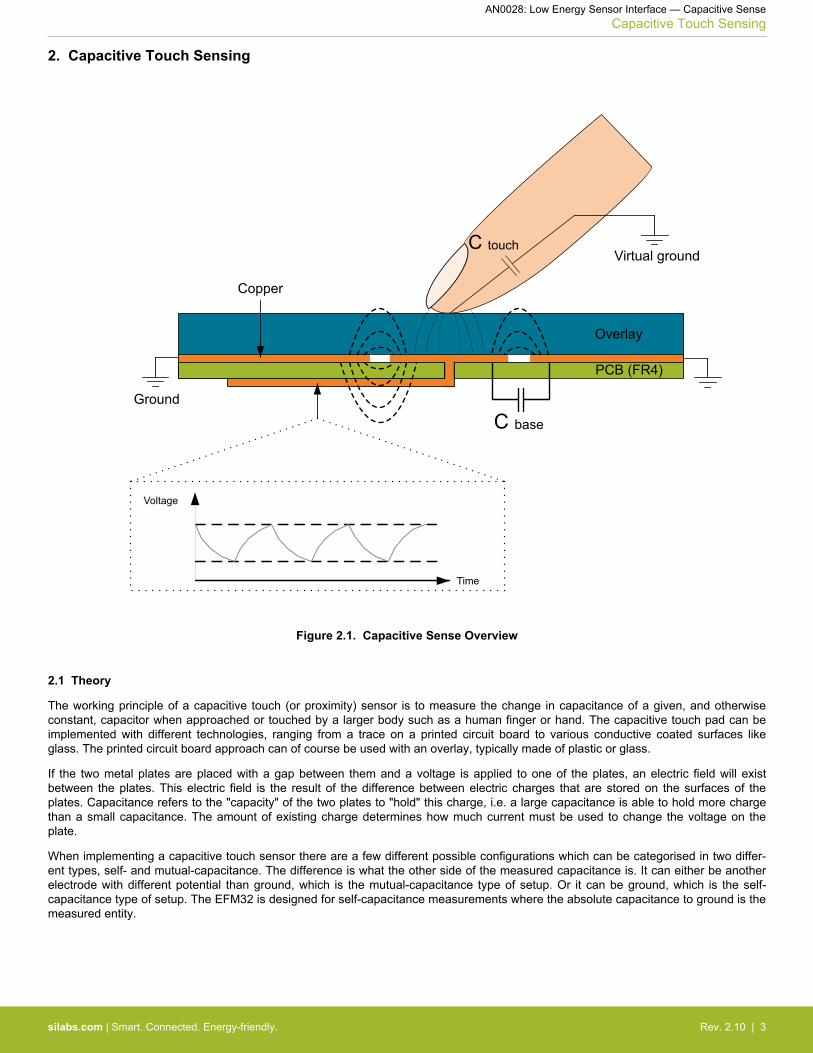
The working principle of a capacitive touch (or proximity) sensor is to measure the change in capacitance of a given, and otherwiseconstant, capacitor when approached or touched by a larger body such as a human finger or hand. The capacitive touch pad can beimplemented with different technologies, ranging from a trace on a printed circuit board to various conductive coated surfaces likeglass. The printed circuit board approach can of course be used with an overlay, typically made of plastic or glass.
If the two metal plates are placed with a gap between them and a voltage is applied to one of the plates, an electric field will existbetween the plates. This electric field is the result of the difference between electric charges that are stored on the surfaces of theplates. Capacitance refers to the "capacity" of the two plates to "hold" this charge, i.e. a large capacitance is able to hold more chargethan a small capacitance. The amount of existing charge determines how much current must be used to change the voltage on theplate.
When implementing a capacitive touch sensor there are a few different possible configurations which can be categorised in two differ-ent types, self- and mutual-capacitance. The difference is what the other side of the measured capacitance is. It can either be anotherelectrode with different potential than ground, which is the mutual-capacitance type of setup. Or it can be ground, which is the self-capacitance type of setup. The EFM32 is designed for self-capacitance measurements where the absolute capacitance to ground is themeasured entity.
AN0028: Low Energy Sensor Interface — Capacitive SenseCapacitive Touch Sensing
silabs.com | Smart. Connected. Energy-friendly. Rev. 2.10 | 3

2.2 Capacitive Sense for the EFM32 Series 0
The analog comparators in the EFM32 Gecko Series 0 include specialized hardware for capacitive sensing of capacitive pads. Thecapacitance is measured by including the pad as a capacitance to ground in a free-running RC oscillator (see the following figure).
By keeping the resistor, drive voltage, and reaction speed of the analog comparator constant, the frequency produced will ideally onlybe dependent on the pad to ground capacitance. Because the user's finger represents both a change in the dielectric material betweenthe plates (pad and ground) and a parallel capacitor to (virtual) ground, it will be seen as a change in the pad capacitance upon touch,see Figure 2.1 Capacitive Sense Overview on page 3.
The frequency produced will thereby decrease when the button is touched, compared to when it is not touched. This frequency changecan be measured. LESENSE does this by counting analog comparator pulses within a fixed time window. A change in count value isused as an indication of a button being touched or not.
VDD/4
VDD_SCALED
Buttons
POSSEL
Figure 2.2. Capacitive Sense in the EFM32
The analog comparator contains a complete feedback loop with an adjustable resistor through which the capacitive pad is charged anddischarged. The output of the analog comparator drives the switches that select the reference for the negative input of the comparator.This feedback will in turn cause the capacitor to charge or discharge as depicted in the following figure. The voltage will oscillate be-tween VDD/4 (lower voltage threshold) and VDD_SCALED (upper voltage threshold).
Voltage
Time
Vdd_scaled
Vdd/4
ACMPOUTCapacitor
charge and discharge
curve
Figure 2.3. Capacitor Charge and Discharge
When the output of the ACMP is high, VDD/4 is selected as reference, and the capacitor starts to discharge due to the inverter. Whenthe capacitor voltage drops below VDD/4 the ACMP output toggles. VDD_SCALED is selected as reference and the capacitor starts charg-ing. When the capacitor voltage again reaches VDD_SCALED the ACMP output toggles and the cycle repeats. The closer VDD_SCALEDand VDD/4 are the shorter the oscillation period will be. The VDD_SCALED reference can be adjusted using the VDDLEVEL bitfield inACMPn_INPUTSEL register. The resulting voltage is given by:
VDD_SCALED = VDD × VDDLEVEL63
AN0028: Low Energy Sensor Interface — Capacitive SenseCapacitive Touch Sensing
silabs.com | Smart. Connected. Energy-friendly. Rev. 2.10 | 4

The frequency of the oscillation is mainly determined by VDD_SCALED, the resistor, the capacitance, and the delay through the analogcomparator. This makes calculating the exact frequency difficult. Fortunately, it is only the change in frequency that is important whendetecting a touch.
2.3 External Disturbances
Touch detection is based on detecting a difference from a "normal" capacitance value. Because of this, it is necessary to keep track ofwhat the untouched capacitance value really is. The problem is that this value will change with the environment. Changes in humidity,for example, will change the base capacitance.
Since the measurement itself is a frequency count during a fixed time window, jitter in measurement-period also affects the untouchedreading of a button in addition to the button capacitance. For example, when the supply voltage, VDD changes, the frequency will alsochange because of a change in pull-level for the RC-oscillator. Another effect that will cause noise in the readout is changes in thesample time window. This can for example be caused by low accuracy oscillator or changes in temperature.
Because a touch event is assumed to be rather quick in nature, slow changes in capacitance and count values are generally easy tofilter out by low pass filtering or taking the median value over time. Fast changing disturbances are more difficult to filter out since a fastchange in capacitance could either be a touching finger or just noise.
As a general rule, slow changes like changes in battery voltage when the battery is discharged, changes in humidity or oscillator fre-quency changes caused by temperature can easily be filtered out. Disturbances that can look like a finger touch on the other handneeds to be minimized, this means that noise on VDD, oscillator jitter and radiated noise from other signals on the PCB should be mini-mized.
2.4 Signal to Noise Ratio
The change in capacitance when a finger is placed near the sensor element is generally very small. This means that the noise level inthe count values needs to be even smaller to be able to reliably detect touches. As a rule of thumb, the signal to noise ratio should beabove 5. The "signal" refers to the difference between the average count for touch and no touch. The ratio between this difference andthe noise-jitter for an untouched button is then the signal to noise ratio. See the figure below for an example of signal to noise ratio.
Note: As a rule of thumb, the signal to noise ratio should be above 5 for good performance.
When developing a capacitive touch application one should check that the signal to noise ratio criterion is fulfilled for the actual PCBwith the final overlay (same material and thickness that will be used). For evaluating the signal level the register view can be used indebug mode, or the actual values can be sent over a serial connection to a computer for analysis.
Count Value
Sample #1 2 .... .... .... N3
Noise [e]
Signal = 5*e
No Touch Values
Touch Values
Figure 2.4. Signal to Noise Ratio
AN0028: Low Energy Sensor Interface — Capacitive SenseCapacitive Touch Sensing
silabs.com | Smart. Connected. Energy-friendly. Rev. 2.10 | 5

3. LESENSE for Capacitive Touch
3.1 Capacitive Touch Sequence
For capacitive touch, there is no need for many of the advanced features of LESENSE like excitation phase, measure delay, or startdelay configurations (see the relevant reference manual). Only the sample delay phase is necessary, and the following list indicates theflow of a measurement for one capacitive touch button. See the following figure for a typical capacitive touch measurement sequence.
1. The analog comparators are switched on in capacitive touch mode. This starts the RC-oscillations on the selected channel.2. The analog comparator output is gated to the LESENSE counter which starts counting. The sample delay counter is started at the
same time.3. When the sample delay counter reaches the configured sample delay, the counted value is stored and compared to a threshold
value.4. If the count compare is true, an interrupt request is sent. Either way, LESENSE turns off the analog comparators again and sleeps
until the next scan cycle. Notice that the CPU itself is never woken up during a measurement cycle.
If LESENSE is configured to scan more than one channel the sequence will repeat itself for each channel in rapid succession beforegoing to sleep. The scan period and sample delay should be configured so there is time to complete the measurement for all channelsbefore a new scan is started. If the desired scan frequency is 100 Hz for example, each scan should not take more than 10 ms, whichagain must be divided between all the channels that is enabled.
STOP
LFACLKLESENSE
Sample delay + 1 cyclesSTARTINIT
RC-oscillations and comparator output
Comparator warm-up and oscillation start
LESENSE Counter
1 2 3 4 5 6 7 8 90
Final Count Value
Figure 3.1. LESENSE Sequence for Capacitive Touch
3.2 LESENSE Configuration
To get the lowest noise level and thereby highest signal to noise ratio, it is important to configure both the analog comparators andLESENSE correctly. The following section lists the different settings, how they affect performance and what they should be set to orhow to tune them. There are other settings that are not directly connected to capacitive touch, the configuration of those can be found inthe software example.
AN0028: Low Energy Sensor Interface — Capacitive SenseLESENSE for Capacitive Touch
silabs.com | Smart. Connected. Energy-friendly. Rev. 2.10 | 6

3.2.1 Fixed Settings
These are settings that can be set to a fixed value which should be optimal for most capacitive touch applications.
Table 3.1. Fixed Settings for Best Capacitive Touch Performance
Setting Optimal value Description
LF oscillator LFXO By using a crystal oscillator the length of the sample windowwill be much more stable. The noise level can be reduced bya factor of 30-40 by using the LFXO instead of the LFRCO.Keep in mind that the LFXO needs an external crystal orclock input to operate.
LESENSE clock prescaler 0: Divide by 1 This is how much the LF clock is prescaled before clockingthe LESENSE module. To get best performance the LE-SENSE module can just be run directly off of the LF clock forcapacitive touch applications.
Analog comparator bias, register values • Full Bias: 1• Half Bias: 1• Bias Prog: 0x5-0x7
The bias current affects the speed of the analog comparator.If the comparator bias current is too low the comparator willcause a significant delay for each oscillation.
This delay will reduce the frequency, but more importantlythe delay is variable and introduces noise-jitter in readings.As long as the bias current is high enough these effects areminimized.
RC-oscillator resistor, register value 0: Smallest resistor The resistor affects the charge/discharge time of the capaci-tive touch element. Higher resistor values corresponds tohigher time-constant for the RC-oscillator. The lowest possi-ble value gives the fastest oscillations and reduce the nee-ded sample delay.
Analog comparator hysteresis, registervalue
0x5 The hysteresis needs to be high enough to not cause falsetriggering.
Analog comparator VDD_SCALED, regis-ter value
0x30 This value determines when the comparator triggers on ris-ing edges. The low threshold is fixed at 0.25 * VDD. Bychanging the VDD_SCALED value, the oscillation speed canbe modified.
A value of 0.75 * VDD ensures a stable frequency without jit-ter. If this value is to close to either VDD or the low triggerthreshold, cycle to cycle jitter will increase, which in turn de-creases the SNR.
Start, excitation and measure delay inclock cycles for the selected clocksource.
• Start Delay: 0• Excitation Delay: 0• Measure Delay: 0
These delays do not affect capacitive touch applications andshould be set to 0.
AN0028: Low Energy Sensor Interface — Capacitive SenseLESENSE for Capacitive Touch
silabs.com | Smart. Connected. Energy-friendly. Rev. 2.10 | 7
3.2.2 Adjustable Settings
These settings can and should be tuned for different capacitive touch applications. A good starting point for a general capacitive touchapplication is given.
Table 3.2. Adjustable Settings for Best Capacitive Touch Performance
Setting Starting point Description
LESENSE scan frequency 5-20 Hz This is how often a scan is started. Each enabled channel isscanned once for every scan start. A good approach to saveenergy can be to have a lower setting when waiting for thefirst touch and then adjust the value for subsequent touchesto give a more responsive user experience.
Sample delay 10-100 LESENSE clock cy-cles
This is the time window measured in LESENSE clock cyclesthat LESENSE gates the analog comparator output to thecounter. The counted value will jitter with 1 LSB even with100% stable input frequency because the comparator signalis asynchronous with respect to the LESENSE clock.
The delay should be high enough to allow for a difference ofat least a few LSB's between touch and no touch. Reducingthis value is the main contribution to lower the energy con-sumption.
Count threshold 1.0% - 50% change fromaverage count value.
This is the threshold that LESENSE compares the count val-ue against in order to determine if the channel in question istouched or not. It should be set so that a touch is detected atthe moment a finger touches the overlay surface.
The value is the percent of change from average untouchedcount. The minimum of 1.0% is based on empirical resultsusing the EFM32 Tiny Gecko Starter Kit with LFXO and ob-serving the noise level. This is then multiplied by 5 for a sig-nal to noise ratio of 5. For a custom PCB this value might beeven lower.
By using percent instead of a fixed value the sample delaycan be changed without also changing this threshold man-ually, given that the code calculates the actual value duringinitialization and calibration. In any case it should be keptabove 5 times the noise level which results in a signal tonoise ratio above 5 as mentioned earlier.
In the software example included, these values are config-ured through the sensitivity[] array.
3.3 Performance Trade-off
The performance trade-off for a capacitive touch application is typically between current consumption and sensitivity. The sensitivitydetermines how thick the overlay can be. These two parameters are inversely correlated, for thick overlays more sensitivity is neededand the current consumption goes up. For thin overlays, or even touch buttons directly on the PCB, the current consumption can bebrought down because a shorter measurement window is sufficient to determine if a touch has occurred.
For LESENSE the sensitivity is increased by increasing the sample delay. This increases the count value and this in turn gives higherresolution in the measurements. While increasing the sample delay, the time the analog comparators are kept running also increases.This increases the current consumption.
The approach to get the correct trade off between low power and good performance is to start out with a large sample delay and firstconfigure the sensitivity by setting the threshold value. The count threshold should be set to a value which gives a touch event at themoment a finger is touching the overlay. Then the sample delay can be decreased until the count value only changes by a few LSBswhen a touch occurs.
AN0028: Low Energy Sensor Interface — Capacitive SenseLESENSE for Capacitive Touch
silabs.com | Smart. Connected. Energy-friendly. Rev. 2.10 | 8

3.3.1 Current Consumption
The software example included, configured for scanning 4 pads at 5 Hz per pad through 1.8 - 2.0 mm of plastic, consumes around 3.4µA. Scanning just 1 pad with the same settings reduces the consumption to approximately 2.1 µA. The current consumption scaleslinearly with scan-frequency, sample delay and the number of pads scanned.
If the PCB layout is made more ideal than the starter kit, with larger pads (1.5 - 2.0 cm), a thicker overlay can be implemented. With thesame settings as above, the total consumption with 6mm overlay for 4 buttons (2.0 cm) at 5 Hz per channel is 3.1 µA. Some examplesof achievable current consumption for different configurations are listed in the table below.
Table 3.3. Current Consumption for Different Software and Hardware Configurations
Hardware Overlay Thick-ness (Plexi-glass)
Sample Delay Count Thresh-old
LESENSE ScanFrequency PerChannel
Buttons Scan-ned
Current Con-sumption (at3.3V)
STK3300 0 mm 1 LFCLK-cycles 40% 5 Hz 1 1.7 µA
STK3300 0 mm 1 LFCLK-cycles 40% 5 Hz 4 1.8 µA
STK3300 0 mm 1 LFCLK-cycles 40% 10 Hz 4 1.9 µA
STK3300 2 mm 30 LFCLK-cycles 1% 5 Hz 1 2.1 µA
STK3300 2 mm 30 LFCLK-cycles 1% 5 Hz 4 3.4 µA
STK3300 2 mm 30 LFCLK-cycles 1% 10 Hz 4 5.0 µA
Custom PCB, 2cm buttons
2 mm 10 LFCLK-cycles 10% 5 Hz 1 2.0 µA
Custom PCB, 2cm buttons
2 mm 10 LFCLK-cycles 10% 5 Hz 4 2.5 µA
Custom PCB, 2cm buttons
2 mm 10 LFCLK-cycles 10% 10 Hz 4 3.1 µA
Custom PCB, 2cm buttons
6 mm 20 LFCLK-cycles 4% 5 Hz 1 2.1 µA
Custom PCB, 2cm buttons
6 mm 20 LFCLK-cycles 4% 5 Hz 4 3.1 µA
Custom PCB, 2cm buttons
6 mm 20 LFCLK-cycles 4% 10 Hz 4 4.3 µA
3.3.2 Temperature and Voltage Variations
The actual count value will vary with voltage and temperature because the analog comparators performance changes with supply volt-age and temperature. Because of this, continuous software calibration is necessary when the count value only changes a few percentupon a touch event. How often a calibration is necessary depends on how quickly the temperature and voltage is expected to change.The actual count value decreases linearly with increasing temperature, about 15% over the temperature range from -40°C to 85°C.
The change over supply voltage is also linear with respect to the change in voltage. The count value increases with increasing supplyvoltage, about 20% over the supply range from 2.0 V to 3.6 V.
AN0028: Low Energy Sensor Interface — Capacitive SenseLESENSE for Capacitive Touch
silabs.com | Smart. Connected. Energy-friendly. Rev. 2.10 | 9
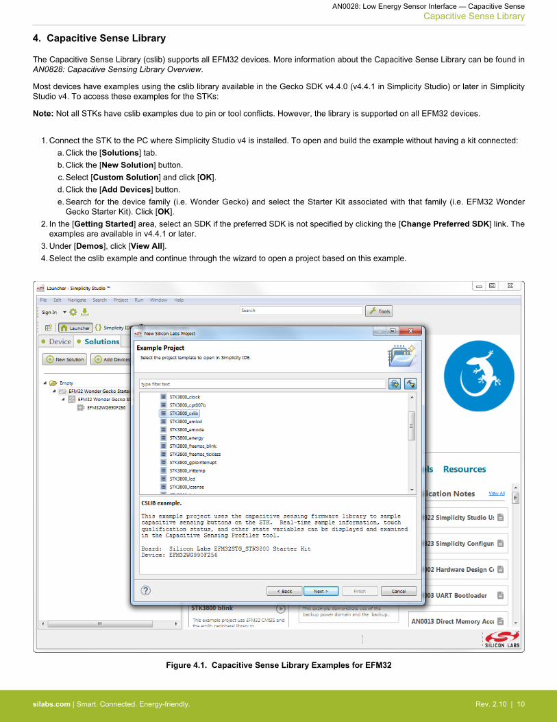
4. Capacitive Sense Library
The Capacitive Sense Library (cslib) supports all EFM32 devices. More information about the Capacitive Sense Library can be found inAN0828: Capacitive Sensing Library Overview.
Most devices have examples using the cslib library available in the Gecko SDK v4.4.0 (v4.4.1 in Simplicity Studio) or later in SimplicityStudio v4. To access these examples for the STKs:
Note: Not all STKs have cslib examples due to pin or tool conflicts. However, the library is supported on all EFM32 devices.
1. Connect the STK to the PC where Simplicity Studio v4 is installed. To open and build the example without having a kit connected:a. Click the [Solutions] tab.b. Click the [New Solution] button.c. Select [Custom Solution] and click [OK].d. Click the [Add Devices] button.e. Search for the device family (i.e. Wonder Gecko) and select the Starter Kit associated with that family (i.e. EFM32 Wonder
Gecko Starter Kit). Click [OK].2. In the [Getting Started] area, select an SDK if the preferred SDK is not specified by clicking the [Change Preferred SDK] link. The
examples are available in v4.4.1 or later.3. Under [Demos], click [View All].4. Select the cslib example and continue through the wizard to open a project based on this example.
Figure 4.1. Capacitive Sense Library Examples for EFM32
AN0028: Low Energy Sensor Interface — Capacitive SenseCapacitive Sense Library
silabs.com | Smart. Connected. Energy-friendly. Rev. 2.10 | 10

5. Software Example
This application note comes with a software example for the EFM32 Tiny Gecko Starter Kit (EFM32TG-STK3300) and the EFM32 GiantGecko Starter Kit (EFM32GG-STK3700). The example uses the capacitive touch slider on the lower right corner of the starter kit. Bytouching one of the slider elements, the user LED is lit during the touch event and turns off again upon no touch.
5.1 Working Principle
The software example simplifies the configuration of LESENSE for capacitive touch. LESENSE is configured to scan the enabled but-tons with a certain scan-frequency and wake up if a button has a count value below a certain threshold. The touch threshold for eachbutton is specified in percent of the average count for an untouched button as described in 3.2.2 Adjustable Settings.
The example uses an RTC interrupt to run a calibration routine. The interval between calibrations can be adjusted for different usagescenarios. The calibration routine tries to find the count values for the untouched buttons. It then reconfigures the wake-up thresholdvalues for LESENSE based on the percent-values configured at initialization.
5.2 Calibration Routine
The calibration routine is executed at fixed intervals. It works by storing count values for each pad from the N previous calibration runs,it then takes the maximum count value seen in the previous N calibration events as the new untouched level.
Since a touch event is always characterized by a decrease in the count value, the system is allowed to quickly calibrate the thresholdcount upwards, but it should take longer to change the threshold down. With this approach it only takes one calibration event to changethe threshold upwards, but it takes N calibration events to change the threshold down. Rising voltage and falling temperature will bothcontribute to an increase in the nominal count values, this will be corrected after one calibration event. Falling voltage and rising tem-perature will result in decreasing nominal count values, this will be corrected after N calibration events.
The calibration routine should be run frequently enough to catch small changes in the untouched count level before it changes enoughto trigger a false touch. To save power it should not be run too frequently either.
The idea is that during the N last calibration events, there should at least be one calibration event that is executed when the user doesnot touch any buttons. The count value from that event will be the maximum count value encountered. In other words, the calibrationcount N multiplied by the interval between calibrations should be higher than the longest expected touch event. If a longer touch eventoccurs, it will only take one more calibration event to get back to the correct threshold value.
In the included software example, both the calibration frequency and N can be adjusted. The default value is 5 seconds between eachcalibration and N = 10. This will contribute less than 100nA to the average current consumption.
5.3 Initialization
To start the capacitive touch operation, an array containing the trigger threshold in percent for each of the LESENSE channels is de-clared and initialized. This is used by the calibration routine to configure the correct thresholds later on.
The calibration routine interval can also be configured depending on how fast supply voltage and other environmental factors are ex-pected to change. Once every 10 seconds with N = 5 to 10 are reasonable values, supply voltage or temperature does not changesignificantly during a couple of minutes. If the application is moved between different environments, and thereby must withstand quickerchanges in environment, the calibration routine can be run more frequently, every second for example.
At start up the calibration routine is executed N times in fast succession, during this period the buttons should not be touched for thecalibration to work correctly. If a pad is touched during this initialization it will only take one calibration event after the touch event isover to correct the threshold value.
5.4 Touch Event
If a count value below the threshold for any channel is observed, LESENSE will trigger an interrupt. The interrupt routine stores andclears the interrupt flag, then it finds the channel that triggered the interrupt. The interrupt routine then reconfigures the scan frequencyand checks the particular channel again a number of times (#define VALIDATE_CNT). This ensures that an actual touch event hasoccurred.
If all the validation measurements are positive, the evaluation criterion on that particular channel is inverted, this will result in a newinterrupt on that particular channel when the touch event is over. By inverting the touch criterion in LESENSE, a minimum amount ofcpu time is spent keeping track of touched and untouched buttons, LESENSE keeps track on its own.
Touch hysteresis is also implemented by changing the threshold value when the touch criterion is inverted. Touch hysteresis preventsthe system from oscillating between touch and no touch events.
AN0028: Low Energy Sensor Interface — Capacitive SenseSoftware Example
silabs.com | Smart. Connected. Energy-friendly. Rev. 2.10 | 11

5.5 Further Improvements
The software example implements some of the basics for a robust touch application. Depending on the application, improvements canstill be made. Some ideas are mentioned in the following section.
By making use of the LESENSE decoder, LESENSE can issue an interrupt for a touch only after a certain number of sequential countvalues are below the touch threshold. This can reduce the energy consumption further.
Implementing use of DMA to transfer count values to memory and do more advanced filtering and processing can also be beneficial.This can be used to differentiate between a water splash or similar disturbance and actual touch events. The collected samples canalso be used to continually adjust the compromise between energy consumption and sensitivity.
A reference pin can be implemented with an unused analog comparator pin. The reference pin should be left unconnected, a usersfinger should not be able to affect it. With a reference pin, environmental changes like temperature and supply voltage can be trackedmore accurately and compensated by adjusting the threshold for the other capacitive touch pins. With this approach, the required as-sumption of untouched buttons in at least one of the N calibration events could be relaxed.
AN0028: Low Energy Sensor Interface — Capacitive SenseSoftware Example
silabs.com | Smart. Connected. Energy-friendly. Rev. 2.10 | 12

6. Revision History
6.1 Revision 2.10
2016-10-14
Updated formatting.
Minor text edits for clarification.
Added 4. Capacitive Sense Library.
6.2 Revision 2.05
2014-05-07
Updated example code to CMSIS 3.20.5
Changed to Silicon Labs license on code examples
Added project files for Simplicity IDE
Removed makefiles for Sourcery CodeBench Lite
6.3 Revision 2.04
2013-10-14
New cover layout
6.4 Revision 2.03
2013-05-08
Added software projects for ARM-GCC and Atollic TrueStudio.
6.5 Revision 2.02
2012-11-12
Adapted software projects to new kit-driver and bsp structure.
Added software support for the Giant Gecko STK.
6.6 Revision 2.01
2012-04-20
Adapted software projects to new peripheral library naming and CMSIS_V3.
Modified ACMP initialization to not use the low power reference. With LESENSE it is automatically not used, but now the ACMP configmatches what actually happens.
6.7 Revision 2.00
2012-03-07
Substantial update of both document and software example.
6.8 Revision 1.00
2011-05-26
Initial revision.
AN0028: Low Energy Sensor Interface — Capacitive SenseRevision History
silabs.com | Smart. Connected. Energy-friendly. Rev. 2.10 | 13

http://www.silabs.com
Silicon Laboratories Inc.400 West Cesar ChavezAustin, TX 78701USA
Simplicity StudioOne-click access to MCU and wireless tools, documentation, software, source code libraries & more. Available for Windows, Mac and Linux!
IoT Portfoliowww.silabs.com/IoT
SW/HWwww.silabs.com/simplicity
Qualitywww.silabs.com/quality
Support and Communitycommunity.silabs.com
DisclaimerSilicon Labs intends to provide customers with the latest, accurate, and in-depth documentation of all peripherals and modules available for system and software implementers using or intending to use the Silicon Labs products. Characterization data, available modules and peripherals, memory sizes and memory addresses refer to each specific device, and "Typical" parameters provided can and do vary in different applications. Application examples described herein are for illustrative purposes only. Silicon Labs reserves the right to make changes without further notice and limitation to product information, specifications, and descriptions herein, and does not give warranties as to the accuracy or completeness of the included information. Silicon Labs shall have no liability for the consequences of use of the information supplied herein. This document does not imply or express copyright licenses granted hereunder to design or fabricate any integrated circuits. The products are not designed or authorized to be used within any Life Support System without the specific written consent of Silicon Labs. A "Life Support System" is any product or system intended to support or sustain life and/or health, which, if it fails, can be reasonably expected to result in significant personal injury or death. Silicon Labs products are not designed or authorized for military applications. Silicon Labs products shall under no circumstances be used in weapons of mass destruction including (but not limited to) nuclear, biological or chemical weapons, or missiles capable of delivering such weapons.
Trademark InformationSilicon Laboratories Inc.® , Silicon Laboratories®, Silicon Labs®, SiLabs® and the Silicon Labs logo®, Bluegiga®, Bluegiga Logo®, Clockbuilder®, CMEMS®, DSPLL®, EFM®, EFM32®, EFR, Ember®, Energy Micro, Energy Micro logo and combinations thereof, "the world’s most energy friendly microcontrollers", Ember®, EZLink®, EZRadio®, EZRadioPRO®, Gecko®, ISOmodem®, Precision32®, ProSLIC®, Simplicity Studio®, SiPHY®, Telegesis, the Telegesis Logo®, USBXpress® and others are trademarks or registered trademarks of Silicon Labs. ARM, CORTEX, Cortex-M3 and THUMB are trademarks or registered trademarks of ARM Holdings. Keil is a registered trademark of ARM Limited. All other products or brand names mentioned herein are trademarks of their respective holders.


![Touch Technologies Tutorial · Emerging Touch Technologies With Multi-Touch [58] Projected Capacitive LCD In-Cell (Optical, Switch & Capacitive) Optical Digital Resistive Waveguide](https://img.dokumen.tips/doc/110x75/6000f3e8fa24967a0f056959/touch-technologies-tutorial-emerging-touch-technologies-with-multi-touch-58-projected.jpg)