Embed Size (px)
Citation preview

(928) 775-9119
120 Union, San Diego, CA
Togawa Smith Martin
Carbon 12, Portland, OR
PATH ArchitectureBy:
R. Terry Malone, PE, SE
Scott Breneman, PhD, PE, SE
Senior Technical Directors
Project Resources and Solutions Division
www.woodworks.org
E-mail: [email protected]
Cantilever Wood Diaphragm Webinar Series
A Design Example of a Wood
Cantilever Diaphragm
Part 4-Torsional Irregularity, Other
Design Checks, and Final Comments

“The Wood Products Council” is a
Registered Provider with The American
Institute of Architects Continuing
Education Systems (AIA/CES), Provider
#G516.
Credit(s) earned on completion of this
course will be reported to AIA CES for
AIA members. Certificates of Completion
for both AIA members and non-AIA
members are available upon request.
This course is registered with AIA CES
for continuing professional education.
As such, it does not include content
that may be deemed or construed to
be an approval or endorsement by the
AIA of any material of construction or
any method or manner of handling,
using, distributing, or dealing in any
material or product.
______________________________
Questions related to specific materials, methods, and services will be addressed at the conclusion of this presentation.

Course Description
This webinar will conclude the open front diaphragm design example by analyzing the degree of torsional irregularity and amplification of accidental torsion. ASCE 7 and SDPWS irregularity code triggers and design impacts will be explained, and verification of the redundancy factor will be reviewed. Other topics will include requirements for the use of overstrength factors for struts and collectors, and new concepts on the connectivity of stacked, multi-story shear walls in wood-frame buildings.

1. Discuss evolutions in mid-rise building typology that have led to the need for open-front diaphragm analysis.
2. Review diaphragm flexibility provisions in ASCE 7 and the 2015 Special Design Provisions for Wind & Seismic (SDPWS).
3. Explore one option for open-front diaphragm analysis under seismic and wind loading in a wood-frame structure.
4. Highlight how to calculate story drift, diaphragm deflection and torsional irregularities, and discover their effects on load distribution through a cantilever diaphragm structure.
Learning Objectives

Fasten Your Seatbelts
5 out of 5 Calculators
Example and Method of Analysis:
• The solutions paper and this webinar were developed independently
from the AWC task group for open-front diaphragms. The method of
analysis used in this example is based on our engineering judgement,
experience, and interpretation of codes and standards as to how they
might relate to open-front structures.
• The analysis techniques provided in this presentation are intended to
demonstrate one method of analysis, but not the only means of analysis.
The techniques and examples shown here are provided as guidance and
information for designers and engineers.

Contents and Learning Objectives
Torsional Irregularity, Other Design Checks,
and Final Comments:
• Torsional irregularity
Torsional irregularity code requirements and the method of analysis used to
determine torsional irregularities will be presented.
• Amplification of accidental torsion
Code requirements regarding amplification of accidental torsion will be
discussed, and the amplification factor will be verified.
• Redundancy
Code requirements and verification of redundancy will be reviewed.
• Transverse direction design
The design will continue for the transverse direction. The selection of a
flexible vs. rigid diaphragm approach will be reviewed.
• Multi-story shear wall effects Multi-story shear wall connectivity and it’s effects will be discussed.
Webinar Part 4 of 4 parts

1. When does a loss in stiffness in the exterior walls cause an open-front diaphragm condition?
2. What is the deflection equation for open-front/cantilever diaphragms?
3. How is diaphragm flexibility defined for open-front/cantilever diaphragms vs. ASCE 7-16, Figure 12.3-1?
4. What are the available methods of distributing torsional forces into the diaphragm?
5. Do shear walls located along diaphragm chord lines affect the diaphragm chord forces?
6. Will the in-plane lateral forces of the exterior walls located at the ends of the cantilever increase chord forces, or is it acceptable to include these as part of the PSF lateral load?
7. How are torsional irregularities determined and addressed for open-front/cantilever diaphragms?
Questions

Torsional Irregularities
.
C.M.
C.R.
.
Lo
ad
s
e
Loads
δ𝐀
δ𝐁
Typical Floor Plan
SW
(Typ.)
Torsional
Irregularity?
Story Drift
Verify Accidental
Torsional
Amplification,
Ax
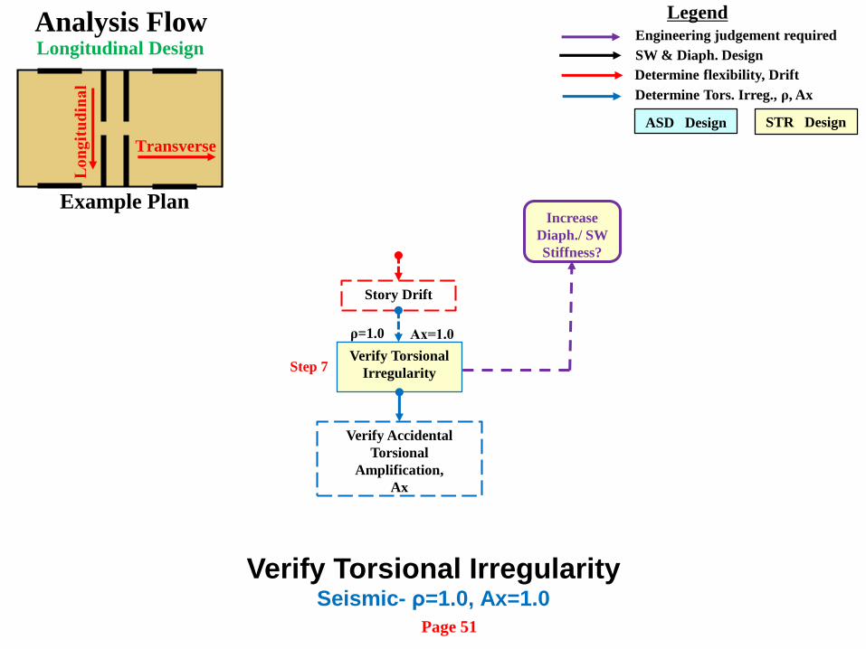
Analysis Flow
ρ=1.0
Increase
Diaph./ SW
Stiffness?
Ax=1.0
Determine flexibility, Drift
SW & Diaph. Design
Determine Tors. Irreg., ρ, Ax
Engineering judgement required
Legend
Longitudinal Design
Step 7
Lo
ng
itu
din
al
Transverse
Example Plan
Verify Torsional
Irregularity
ASD Design STR Design
Verify Torsional IrregularitySeismic- ρ=1.0, Ax=1.0
Page 51

In many cases, open-front structures will result in torsional irregularities because of
rotational effects.
SDPWS Section 4.2.5.1 addresses ASCE 7-16 torsional irregularity requirements.
Torsional Irregularity Type 1a – seismic - Maximum story drift, ∆MAX, (including
accidental torsion with AX=1.0), > 1.2x ∆ADVE
• Model as semi-rigid or idealized as rigid
• Torsional irregularity, Type 1a, is allowed in structures assigned to SDC B, C,
D, E, or F.
Torsional Irregularity Type 1b - seismic: Extreme torsionally irregular, Maximum
drift, ∆MAX > 1.4 x ∆ADVE
• An extreme torsional irregularity Type 1b is allowed in structures assigned to
Seismic Design Categories B, C, and D, but not in SDC E, or F.
Torsional Irregularities ρ = 1.0 and Ax = 1.0
ASCE 7-16 Table 12.3-1, Type 1a and 1b irregularities note that Ax=1.0 when
checking for torsional irregularities.
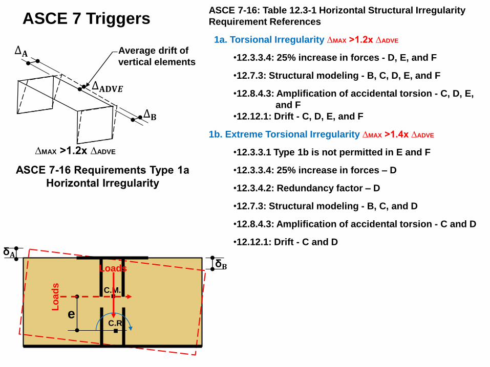
Average drift of
vertical elements
ASCE 7-16: Table 12.3-1 Horizontal Structural Irregularity
Requirement References
1a. Torsional Irregularity ∆MAX >1.2x ∆ADVE
•12.3.3.4: 25% increase in forces - D, E, and F
•12.7.3: Structural modeling - B, C, D, E, and F
•12.8.4.3: Amplification of accidental torsion - C, D, E,
and F
•12.12.1: Drift - C, D, E, and F
1b. Extreme Torsional Irregularity ∆MAX >1.4x ∆ADVE
•12.3.3.1 Type 1b is not permitted in E and F
•12.3.3.4: 25% increase in forces – D
•12.3.4.2: Redundancy factor – D
•12.7.3: Structural modeling - B, C, and D
•12.8.4.3: Amplification of accidental torsion - C and D
•12.12.1: Drift - C and D
.
C.M.
C.R.
.
Lo
ad
s
e
Loads
δ𝐀δ𝐁
∆𝐀
∆𝐁
ASCE 7-16 Requirements Type 1a
Horizontal Irregularity
∆MAX >1.2x ∆ADVE
∆𝐀𝐃𝐕𝑬
ASCE 7 Triggers

Longitudinal LoadingGrid Line kx Ky dx dy kd Fv FT Fv+FT
2 43.54 3 130.63 391.89 8884.5 -422.2 8462.3
3 43.54 3 130.63 391.89 8884.5 422.2 9306.7
A 25.14 20 502.74 10054.73 1624.7 1624.7
B 25.14 20 502.74 10054.73 -1624.7 -1624.7
Σ 87.09 50.27 J= 20893.23 17769
e=3.8’, T = 67522.2 ft. lbs. ρ=1.0, Ax=1.0
Wa
lls
at
Gri
d
lin
es
A &
B
Co
rrid
or
Wa
lls
Torsional Irregularity Check-Method 2A
ρ=1.0, Ax=1.0
Rt. CantileverΣδ_slip v unif. v conc. Ga L' W' δDiaph Unif δDiaph conc Total δF 15 F23 F35 In. plf plf k/in. Ft. Ft. In. In. In.982.0 1235.5 3538.6 0.003 227.22 0.00 25.0 35.00 40.00 0.188 0.00 0.188 Nails Req'd= 4.35 5.47 15.66 Use Nails = 8 16 24 Slip= 0.021 0.013 0.025 EA= 28050000, (2)2x6 235.28Iincludes effects of sw's along chord line 231.77 W2 W1233.53 233.531.75 -1.758452.3 9295.7 235.28 231.77Diaphragm Deflection (STR) Lft. Cantilever331.6 1852.9 3613.1 0.003 224.16 #VALUE! 25.0 35.00 40.00 0.185 0.00 0.185 1.47 8.20 15.998 16 240.007 0.020 0.026
Diaphragm Deflection (STR) Splice Forces (Lbs.)
Method 2A
Chord spliceChord splice Chord spliceChord splice
Rt. Cantilever
Σδ_slip v unif. v conc. Ga L' W' δDiaph Unif δDiaph conc Total δ
F 15 F23 F35 In. plf plf k/in. Ft. Ft. In. In. In.
983.2 1236.9 3542.8 0.075 227.49 0.00 25.0 35.00 40.00 0.260 0.00 0.260
Nails Req'd= 4.35 5.47 15.68
Use Nails = 8 16 24
Slip= 0.021 0.013 0.025
EA= 28050000, (2)2x6 235.56
Iincludes effects of sw's along chord line 232.05
W2
233.80
1.75
8462.3 9306.7 235.56
Diaphragm Deflection (STR) Lft. Cantilever
332.0 1855.1 3617.4 0.073 224.42 0.00 25.0 35.00 40.00 0.256 0.00 0.256
1.47 8.21 16.01
8 16 24
0.007 0.020 0.026
Diaphragm Deflection (STR)
Splice Forces (Lbs.)
Method 2A
Ch
ord
sp
lice
Ch
ord
sp
lice
Ch
ord
sp
lice
Ch
ord
sp
lice
Page 52

SW
SW
3 4
A
B
SW
SW
W’=40’
6’
1 2
SW
SW
SW
SW
20’
20’
Diaphragm
deflection
L’+3’ = 38’
𝜽
W’/
2
SW
SW
δ𝑹𝑻 = 𝟎. 𝟎𝟔𝟓"
∆ = 𝟎. 𝟏𝟒"
232.05 plf235.56 plf
∆𝑨𝑫𝑽𝑬=0.204”
δ𝐌𝐃𝐃 =0.26”
δ𝑹𝑻 = 𝟎. 𝟎𝟔𝟓"
∆𝟏= 𝟎. 𝟏𝟗𝟒"
- δ𝑹𝑳 = 𝟎. 𝟏 𝟒"
+δ𝑹𝑳 = 𝟎. 𝟏 𝟒"
δ𝐃= 0.260”
∆=
Dri
ft
∆=
Dri
ft
δ𝐓 = 𝟎. 𝟎𝟕"
δ𝐃= 0.256”
∆Drift = δ𝐓+(δ𝐃- δ𝑹𝑳)
δ𝐃- δ𝑹𝑳
Torsion (Question 7):

Check for Torsional Irregularity Type 1a - ρ=1.0, Ax=1.0
SDPWS 4.2.5.2 (2):
A.R. ≤ 1:1 if torsional irregularity - one-story structure
A.R. = 0.67:1 - multi-story structure
A.R. = 0.875 < 1, ⸫ O.K. Had this been a multi-story structure, the A.R. would
have been exceeded and adjustments made accordingly.
∆𝑨𝒗𝒆𝒓=𝟎. 𝟏𝟗𝟒 + 𝟎. 𝟏𝟒
= 𝟎. 𝟎𝟒"
Diaphragm deflections:
𝜹𝑫,𝟏=0.256”
𝜹𝑫,𝟒=0.260”
𝜹𝑺𝑾𝑨,𝑩=0.065” = 𝜹𝑹𝑻 Transverse displacement at Lines A and B
from rigid diaphragm rotation
δRL = 𝜹𝑺𝑾𝑨,𝑩(𝑳
′+𝟑′)
𝑾′=0.124” Vertical component of rotation
∆ = 𝟎. 𝟏𝟗𝟒", ∆3=0.214"

0.592 > 1.2(0.467) = 0.56”, ⸫ Horizontal torsional
irregularity Type 1a does exist in this direction.
Drift ∆= (𝜹𝑻 + 𝜹𝑫±𝜹𝑹𝑳) +(𝜹𝑹𝑻)
Drift ∆4 = (𝟎. 𝟎𝟒 + 𝟎. 𝟔𝟎 + 𝟎. 𝟏 𝟒) +(𝟎. 𝟎𝟔𝟓) = 𝟎. 𝟓𝟗 "
Drift ∆1 = (𝟎. 𝟎𝟒 + 𝟎. 𝟓𝟔 − 𝟎. 𝟏 𝟒) +(𝟎. 𝟎𝟔𝟓) = 𝟎. 𝟑𝟒 "
∆𝑨𝒗𝒆𝒓=𝟎. 𝟓𝟗 + 𝟎. 𝟑𝟒
= 𝟎. 𝟒𝟔𝟕"
0.592 < 1.4(0.467) = 0.654”, ⸫ Horizontal torsional
irregularity Type 1b does not exist in this direction.

Amplification of Accidental Torsion
.
C.M.
C.R.
.L
oa
ds
e
Loads
δ𝐀
δ𝐁
Seismic- ρ=1.0, Ax=1.0

Verify accidental
ecc. ampl., Ax
Verify Rho
ρ
Analysis Flow
Ax=1.0
Determine flexibility, Drift
SW & Diaph. Design
Determine Tors. Irreg., ρ, Ax
Engineering judgement required
Legend
Longitudinal Design
Step 8
ρ=1.0
Lo
ng
itu
din
al
Transverse
Example Plan
Verify Torsional
Irregularity
ASD Design STR Design
Page 54
Verify Amplification of Accidental Torsion, AxSeismic- ρ=1.0, Ax=1.0

ASCE 7-16 12.8.4.3 Amplification of Accidental Torsional Moment.
Structures assigned to Seismic Design Category C, D, E, or F, where Type 1a or 1b
torsional irregularity exists as defined in Table 12.3-1 shall have the effects accounted
for by multiplying Mta at each level by a torsional amplification factor (Ax) as illustrated
in Fig. 12.8-1 and determined from the following equation:
𝑨𝒙 =𝜹𝒎𝒂𝒙
𝟏. 𝜹𝒂𝒗𝒈
12.8-14
Where
δmax =maximum displacement at level x computed assuming Ax = 1
δavg =average of the displacements at the extreme points of the structure
at level x computed assuming Ax = 1.
Mta =accidental torsional moment
From torsion section:
𝑨𝒙 =𝜹𝒎𝒂𝒙
𝟏. 𝜹𝒂𝒗𝒈
=𝟎.𝟓𝟗
𝟏. (.𝟒𝟔𝟕)
= 1.116 < 1.25 assumed.
⸫ Can recalculate if desired.
δ𝐁δ𝐀
ASCE 7-16 Figure 12.8-1Amplification of accidental torsion
ASCE 7-10 (1st printing) 12.8.4.1 Inherent Torsion Exception below is not in 3rd printing of ASCE 7-10 or ASCE 7-16
Most diaphragms of light-framed construction are somewhere between rigid and flexible for analysis purposes, that is, semi-
rigid. Such diaphragm behavior is difficult to analyze when considering torsion of the structure. As a result, it is believed that
consideration of the amplification of the torsional moment is a refinement that is not warranted for light-framed
construction.

Verify accidental
ecc. ampl., Ax
Verify Rho
ρ
Analysis Flow
Determine flexibility, Drift
SW & Diaph. Design
Determine Tors. Irreg., ρ, Ax
Engineering judgement required
Legend
Longitudinal Design
Step 9
ρ=1.0 Ax=1.0
Lo
ng
itu
din
al
Transverse
Transverse
Design
Example Plan
ASD Design STR Design
Page 54
Verify Redundancy, ρSeismic- ρ=1.0, Ax=1.0
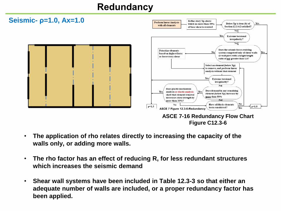
Redundancy
• The application of rho relates directly to increasing the capacity of the
walls only, or adding more walls.
• The rho factor has an effect of reducing R, for less redundant structures
which increases the seismic demand
• Shear wall systems have been included in Table 12.3-3 so that either an
adequate number of walls are included, or a proper redundancy factor has
been applied.
Seismic- ρ=1.0, Ax=1.0
ASCE 7-16 Redundancy Flow Chart
Figure C12.3-6

12.3.4.1 Conditions Where Value of ρ is 1.0. The value of ρ is permitted to equal 1.0 for
the following:
2. Drift calculation and P-delta effects.
5. Design of collector elements, splices, and their connections for which the seismic
load effects including over-strength factor of section 12.4.3 are used.
6. Design of members or connections where seismic load effects including over
-strength factor of section 12.4.3 are required for design.
7. Diaphragm loads, Fpx, determined using Eq. 12.10-1, including min. & max.
values.
12.3.4.2 Redundancy Factor, ρ, for Seismic Design Categories D through F.
• For structures assigned to Seismic Design Category D and having extreme
torsional irregularity as defined in Table 12.3-1, Type 1b, ρ shall equal 1.3.
• For other structures assigned to Seismic Design Category D and for structures
assigned to Seismic Design Categories E or F, ρ shall equal 1.3 unless one of the
following two conditions (a. or b.) is met, whereby ρ is permitted to be taken as
1.0.
Let’s check condition b. first

Lo
ad
s
Loads
b. Structures that are regular in plan at all levels
ρ=1.0 provided:
• SFRS consist of at least two bays of
perimeter SFRS framing on each side of the
structure in each orthogonal direction at
each story resisting more than 35% of the
base shear.
• The number of bays for a shear wall = LSW /
hsx, or 2LSW / hsx, for light-frame
construction.
Although the plan is regular, in the longitudinal
direction, there are no SFRS walls at all exterior
wall lines. Therefore, the structure does not comply
with condition “b”, and condition “a” must be met.
No. bays=2(8)(2)/10=3.2 bays
(But not all 4 sides)
Table 12.3-3.
A.R. = 1.25:1
A.R
. =
1:1
No wall
A.R. > 1:1
reduction in story
Strength =0%(33% reduction
allowed)
reduction in story
Strength =25%
Therefore condition “a” has
been met and ρ=1.0.
A.R. = 1.25:1
Lo
ng
itu
din
al
Transverse
A.R
. =
1:1
A.R. = 1.25:1
• Removing one wall segment with A.R. > 1:1 will
not result in reduction in story strength > 33%
limit.
• Removing 1 wall within any story will not result
in extreme torsional irregularity, Type 1b.
Condition a.Each story resisting more than 35% of the base
shear in the direction of interest shall comply
with Table 12.3-3.

3 4
A
B
W’=40’
6’
1 2
20’
20’
Diaphragm
deflection
L’+3’ = 38’
𝜽
δ𝒔𝒘𝑨
∆
231.22 plf236.38 plf
∆𝑻
δ𝐌𝐃𝐃
δ𝒔𝒘𝑩
∆𝟏
- δ𝑹𝑻+δ𝑹𝑻
δ𝐃
δ𝐃
∆=
Dri
ft
∆=
Dri
ft
δ𝐓 =∆A𝑫𝑽𝑬
13
.33
3’
26.6
67’
6.6
67
’C.M.
C.R.
ΣK
=43
.54
ഥ𝒀 =𝟏𝟓.𝟖𝟕𝟓(𝟒𝟎)
𝟑(𝟏𝟓.𝟖𝟕𝟓)= 13.33’
𝑯
𝑳= 𝟏𝟎
𝟖= 𝟏. 𝟓 > 𝟏. 𝟎
⸫ remove
Ax=1.0ρ=1.0
ΣK
=43
.54
𝐊 = 𝟏 . 𝟓𝟕
δ𝐃- δ𝑹𝑳
∆Drift = δ𝐓+(δ𝐃- δ𝑹𝑳)
𝐊 = 𝟏 . 𝟓𝟕𝐊 = 𝟏 . 𝟓𝟕
Page 56
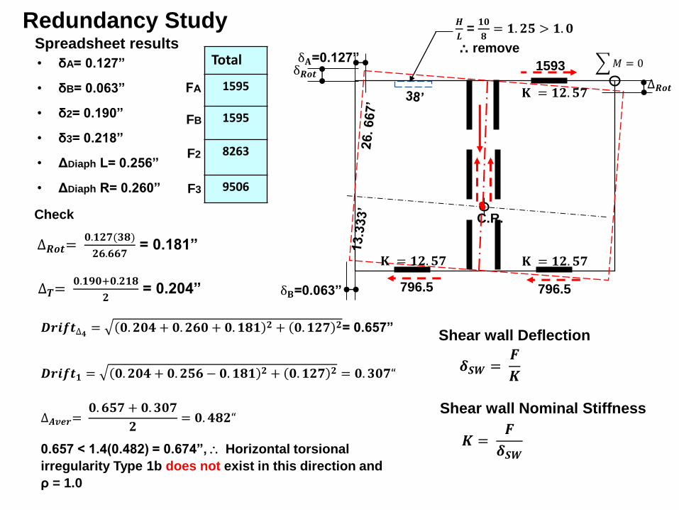
Redundancy Study
𝑀 = 0δ𝑹𝒐𝒕
δ𝐁=0.063”
δ𝐀=0.127”
𝑯
𝑳= 𝟏𝟎
𝟖= 𝟏. 𝟓 > 𝟏. 𝟎
⸫ remove
C.R.
∆𝑹𝒐𝒕=𝟎.𝟏 𝟕(𝟑𝟖)
𝟔.𝟔𝟔𝟕= 0.181”
∆𝑹𝒐𝒕
• δA= 0.127”
• δB= 0.063”
• δ2= 0.190”
• δ3= 0.218”
• ΔDiaph L= 0.256”
• ΔDiaph R= 0.260”
Total
1595
1595
8263
9506
1593
796.5 796.5∆𝑻=𝟎.𝟏𝟗𝟎+𝟎. 𝟏𝟖
= 0.204”
𝑫𝒓𝒊𝒇𝒕∆𝟒 = 𝟎. 𝟎𝟒 + 𝟎. 𝟔𝟎 + 𝟎. 𝟏𝟖𝟏 + 𝟎.𝟏 𝟕 = 0.657”
𝑫𝒓𝒊𝒇𝒕𝟏 = 𝟎. 𝟎𝟒 + 𝟎. 𝟓𝟔 − 𝟎. 𝟏𝟖𝟏 + 𝟎.𝟏 𝟕 = 𝟎. 𝟑𝟎𝟕“
∆𝑨𝒗𝒆𝒓=𝟎. 𝟔𝟓𝟕 + 𝟎. 𝟑𝟎𝟕
= 𝟎. 𝟒𝟖 “
0.657 < 1.4(0.482) = 0.674”, Horizontal torsional
irregularity Type 1b does not exist in this direction and
ρ = 1.0
Check
FA
FB
F2
F3
Spreadsheet results
𝐊 = 𝟏 . 𝟓𝟕𝐊 = 𝟏 . 𝟓𝟕
𝐊 = 𝟏 . 𝟓𝟕
𝜹𝑺𝑾 =𝑭
𝑲
Shear wall Deflection
𝑲 =𝑭
𝜹𝑺𝑾
Shear wall Nominal Stiffness

12.10.2 SDC B - Collectors can be designed w/o over-strength
but not if they support discontinuous walls or frames.
12.10.2.1 SDC C thru F- Collectors and their connections, including connections to the vertical resisting
elements require the over-strength factor of Section 12.4.3, except as noted:
Shall be the maximum of:
𝛀𝒐𝑭𝒙 - Forces determined by ELF Section 12.8 or Modal Response Spectrum Analysis
procedure 12.9
𝛀𝒐 𝑭𝒑𝒙 - Forces determined by Diaphragm Design Forces (Fpx), Eq. 12.10-1 or
𝑭𝒑𝒙𝒎𝒊𝒏= 𝟎. 𝑺𝑫𝑺𝑰𝒆𝒘𝒑𝒙 - Lower bound seismic diaphragm design forces determined by
Eq. 12.10-2 (Fpxmin) using the Seismic Load Combinations of section
12.4.2.3 (w/o over-strength)-do not require the over-strength factor.
Struts / collectors and their connections shall be designed in accordance with
ASCE 7-16 sections:
Exception:
1. In structures (or portions of structures) braced entirely by light framed shear walls, collector
elements and their connections, including connections to vertical elements need only be designed
to resist forces using the standard seismic force load combinations of Section 12.4.2.3 with forces
determined in accordance with Section 12.10.1.1 (Diaphragm inertial Design Forces, 𝑭𝒑𝒙).
Struts and Collectors-Seismic
𝑭𝒑𝒙𝒎𝒂𝒙= 𝟎. 𝟒𝑺𝑫𝑺𝑰𝒆𝒘𝒑𝒙- Upper bound seismic diaphragm design forces determined by
Eq. 12.10-2 (Fpxmax) using the Seismic Load Combinations of section
12.4.2.3 (w/o over-strength)-do not require the over-strength factor.
and
Same
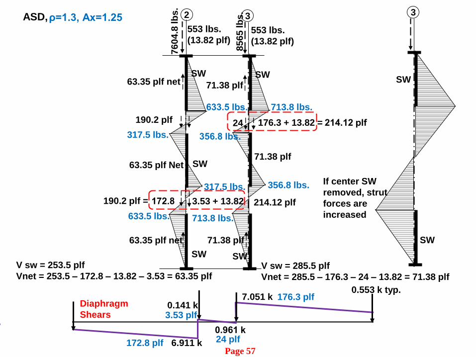
SW
3
24
V sw = 285.5 plf
Vnet = 285.5 – 176.3 – 24 – 13.82 = 71.38 plf
71.38 plf
356.8 lbs.
71.38 plf
SW
SW
2
190.2 plf
V sw = 253.5 plf
Vnet = 253.5 – 172.8 – 13.82 – 3.53 = 63.35 plf
63.35 plf net
633.5 lbs.
63.35 plf net
SW
76
04
.8 lb
s.
85
65
lb
s.
553 lbs.
(13.82 plf)
633.5 lbs.
3.53 + 13.82172.8
63.35 plf Net SW
317.5 lbs.
317.5 lbs.
553 lbs.
(13.82 plf)
190.2 plf =
176.3 + 13.82 = 214.12 plf
713.8 lbs.
713.8 lbs.
356.8 lbs.
71.38 plf
176.3 plf
6.911 k
0.141 k
0.961 k
7.051 kDiaphragm
Shears
24 plf172.8 plf
3.53 plf
0.553 k typ.
ASD, ρ=1.3, Ax=1.25
SW
3
SW
If center SW
removed, strut
forces are
increased
214.12 plf
Page 57

Design Example- Transverse Direction
SW
Sym.
C.L.
Sym.
C.L.
SW
S
W
Unit 1
Unit 4Unit 3
Unit 2
SW
SW
SW
W 3
W 4
SW SW
SW SW

Verify
Redundancy
Analysis Flow
Determine flexibility, Drift
SW & Diaph. Design
Determine Tors. Irreg., ρ, Ax
Engineering judgement required
Legend
Longitudinal Design
Step 10
Step 11
Step 12
Lo
ng
itu
din
al
Transverse
Verify Final
Diaph. Design
Diaph. Inertial
Design Force
Fpx or MSFRS
Transverse Design
Verify Drift and
Torsional Irreg.
Verify Rho
ρ
ρ=1.0 Ax=1.0 ρ=1.0 Ax=1.0
Example Plan
ρ=1.3 Ax=1.0
ASD Design STR Design
12.3.1.1- (c), Light framed construction, diaphragms meeting all the following
conditions are allowed to be idealized as flexible:
1. All Light framed construction
2. Non-structural concrete topping ≤ 1 ½” over wood structural panels (WSP).
3. Each elements of the seismic line of vertical force-resisting system
complies with the allowable story drift of Table 12.12-1
Transverse DesignSeismic- ρ=1.3, Ax=1.0
Flexible assumed
Page 58

-
12’ 8’ 15’
SW
C.R.
C.M.
3 4
A
B
SW
SW
SW
+
1 2
6’
W=40’
Diaphragm
transfer
shears
SW
SW
9953.4
7815.6
SW
SW
L=76’
L’ = 35’
Diaphragm
Case 3
SW
SW
Chord
splice
Chord
splice
Chord
splice
∆𝒔𝒘𝑨= 𝟎. 𝟑𝟗𝟔"
∆𝒔𝒘𝑩= 𝟎. 𝟑𝟏𝟏"
Ch
ord
Ch
ord
d=76’
Drift
ρ=1.0, Ax=1.25
W=
55
1.1
plf
W=
33
7.3
plf
ρ=1.0, Ax=1.0
Torsional and Redundancy Check
Page 60, 61

W= 17769/76=444.1 plf (ASD)
VA=9057.6 lbs.
Vmax Diaph = 𝟗𝟎𝟓𝟕.𝟔
𝟕𝟔= 119.2 plf < 464 plf ⸫ O.K
From spreadsheet (STR)
𝜹𝑫𝒊𝒂𝒑𝒉 = 𝟎. 𝟎𝟔𝟔“
𝜟𝑺𝑾 𝑨 = 0.396”, 𝜟𝑺𝑾 𝑩 = 0.311”, 𝒙𝜟𝑨𝒗𝒆𝒓𝒂𝒈𝒆 = 𝟎. 𝟕𝟎𝟕“
0.066” < 0.707” ⸫ Rigid diaphragm, as initially assumed.
Diaphragm Flexibility, Resulting numbers: ρ=1.0, Ax=1.25
Check Story Drift
ρ =1.0 and Ax = 1.25
Cd = 4, Ie = 1
𝛅𝐒𝐖𝐀 = 𝟎. 𝟑𝟗𝟔 𝐢𝐧 𝐟𝐫𝐨𝐦 𝐬𝐩𝐫𝐞𝐚 𝐬𝐡𝐞𝐞𝐭
𝛅𝐌 =𝐂 𝛅𝐦𝐚𝐱
𝐈𝐞=
𝟒(𝟎.𝟑𝟗𝟔)
𝟏= 𝟏. 𝟓𝟖 𝐢𝐧
0.020 hsx = 0.020(10)(12) = 2.4 in > 1.58 in, ⸫ Drift OK

Check for Torsional Irregularity
Rigid diaphragm, ρ =1.0 and Ax = 1.0 as required by ASCE 7 Table 12.3-1
From spreadsheet
𝜹𝑺𝑾𝑨=0.387”
𝜹𝑺𝑾𝑩=0.319”
𝜟𝑨𝒗𝒆𝒓𝒂𝒈𝒆 =𝟎.𝟑𝟖𝟕+𝟎.𝟑𝟏𝟗
= 𝟎. 𝟑𝟓𝟑" From spreadsheet
0.387 < 1.2(0.353) = 0.424”, ⸫ No torsional irregularity
exists in this direction, as assumed.
ρ=1.0, Ax=1.0
13
.33
3’
26
.66
7’
6.6
67
’
C.M.
C.R.
ΣK
=4
3.5
4
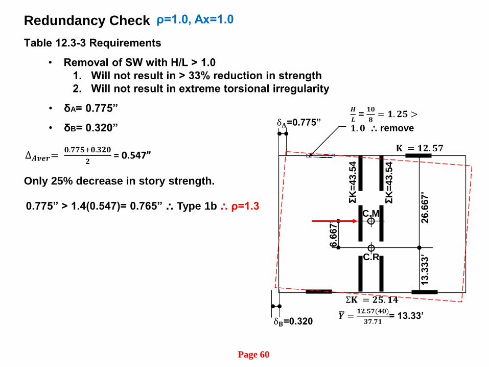
Σ𝐊 = 𝟓. 𝟏𝟒
ഥ𝒀 =𝟏 .𝟓𝟕(𝟒𝟎)
𝟑𝟕.𝟕𝟏= 13.33’
Table 12.3-3 Requirements
• Removal of SW with H/L > 1.0
1. Will not result in > 33% reduction in strength
2. Will not result in extreme torsional irregularity
𝑯
𝑳= 𝟏𝟎
𝟖= 𝟏. 𝟓 >
𝟏. 𝟎 ⸫ remove
𝐊 = 𝟏 . 𝟓𝟕
ΣK
=43
.54
∆𝑨𝒗𝒆𝒓=𝟎.𝟕𝟕𝟓+𝟎.𝟑 𝟎
= 0.547”
• δA= 0.775”
• δB= 0.320”
0.775” > 1.4(0.547)= 0.765” ⸫ Type 1b ⸫ ρ=1.3
Only 25% decrease in story strength.
δ𝐁=0.320
δ𝐀=0.775”
Redundancy Check ρ=1.0, Ax=1.0
Page 60

Preliminary Assumptions Made:
• Diaphragm is rigid or semi-rigid in both directions. Correct
• Torsional irregularity Type 1a occurs in longitudinal direction, but not
transverse, Correct
• Ax=1.25 assumed. Incorrect, Ax=1.121
• Horizontal irregularity Type 1b does not occur in either direction. Correct,
however, when checking redundancy, it occurs in the transverse direction
by the removal of 1 wall.
• No redundancy in both directions, ρ=1.3 Incorrect:
• ρ = 1.0 Longitudinal
• ρ = 1.3 Transverse
Other Design Requirements:
• Drift < allowable
Example Summary
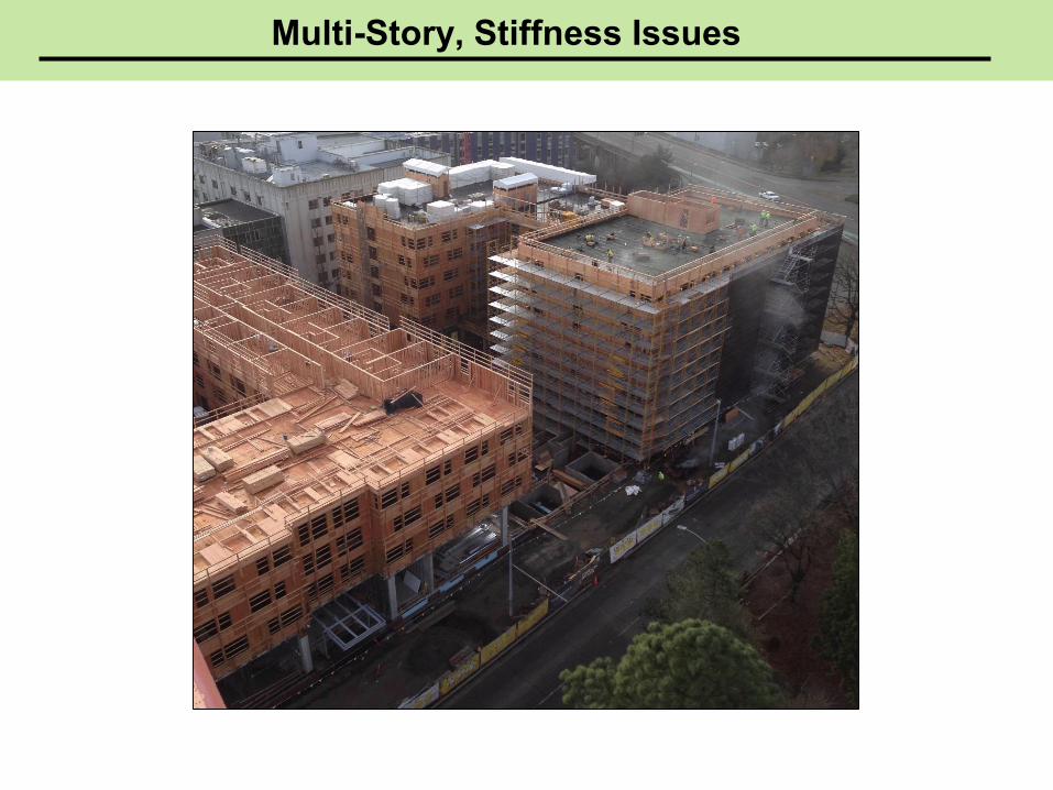
Multi-Story, Stiffness Issues
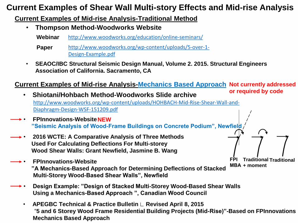
Current Examples of Mid-rise Analysis-Traditional Method
• APEGBC Technical & Practice Bulletin Revised April 8, 2015
“5 and 6 Storey Wood Frame Residential Building Projects (Mid-Rise)”-Based on FPInnovations
Mechanics Based Approach
• FPInnovations-Website ”Seismic Analysis of Wood-Frame Buildings on Concrete Podium”, Newfield
• Shiotani/Hohbach Method-Woodworks Slide archivehttp://www.woodworks.org/wp-content/uploads/HOHBACH-Mid-Rise-Shear-Wall-and-Diaphragm-Design-WSF-151209.pdf
• Design Example: ”Design of Stacked Multi-Storey Wood-Based Shear Walls Using a Mechanics-Based Approach ”, Canadian Wood Council
Current Examples of Shear Wall Multi-story Effects and Mid-rise Analysis
FPIMBA
Traditional+ moment
Traditional
• 2016 WCTE: A Comparative Analysis of Three Methods
Used For Calculating Deflections For Multi-storey
Wood Shear Walls: Grant Newfield, Jasmine B. Wang
• FPInnovations-Website
”A Mechanics-Based Approach for Determining Deflections of Stacked Multi-Storey Wood-Based Shear Walls”, Newfield
NEW
http://www.woodworks.org/education/online-seminars/
• Thompson Method-Woodworks Website
Webinar
http://www.woodworks.org/wp-content/uploads/5-over-1-Design-Example.pdf
Paper
Current Examples of Mid-rise Analysis-Mechanics Based Approach
• SEAOC/IBC Structural Seismic Design Manual, Volume 2. 2015. Structural Engineers
Association of California. Sacramento, CA
Not currently addressed or required by code

A.R.
h/d ≤ 2:1
New Research and Analytical methods-Tall Shear WallsCurrently not addressed or required by code:
Engineering preference and/or judgement
• Current research suggests that The
traditional method of shear wall analysis
might be more appropriate for low-rise
structures.
Tra
dit
ion
al
Me
tho
d
Ta
ll W
all
Me
tho
d
Testing shows that the traditional deflection
equation is less accurate for walls with aspect
ratios higher than 2:1.
(Dolan)
Tall Shear Wall
MBA
Floor to floor A.R.’s and Stiffness of Shear Walls
• Multi-story walls greater than 3 stories
should:
▪ Consider flexure and wall rotation.
▪ Rotation and moment from walls above
and wall rotation effects from walls
below.
𝐒𝐖
Ta
ll 𝐒𝐖
Sti
ffn
ess
ba
sed
ap
pro
ach
∆𝐀𝐥𝐥𝐨𝐰 𝐬𝐭𝐨𝐫𝐲 𝐫𝐢𝐟𝐭
Allowable story drift for traditional
and tall shear walls is checked
floor to floor.
Total displ. of
Tall Wall. More
flexible.
A.R.=3.5:1
flr.-flr.
Total displ.
Traditional
walls
A.R.=2:1
flr.-flr.
Act
ing a
s a c
on
tin
uou
s w
all
∑𝑴𝒊𝑯𝒊
𝑬𝑰 𝒊+∑𝑽𝒊 𝑯
𝟑
𝟑 𝑬𝑰 𝒊
Moment from walls above
Rotation from walls
above and below.
Traditional based
on A.R.MBA based
on stiffness
Not in example
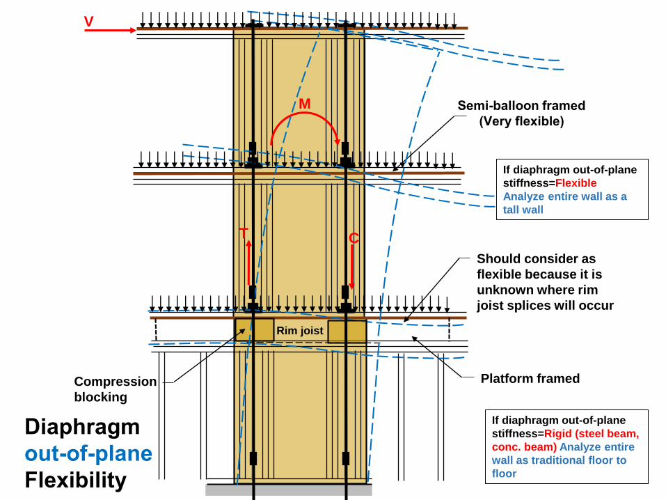
Rim joist
Should consider as
flexible because it is
unknown where rim
joist splices will occur
Platform framed
Semi-balloon framed
(Very flexible)
If diaphragm out-of-plane
stiffness=Flexible
Analyze entire wall as a
tall wall
If diaphragm out-of-plane
stiffness=Rigid (steel beam,
conc. beam) Analyze entire
wall as traditional floor to
floor
Compression
blocking
V
CT
M
Diaphragm
out-of-plane
Flexibility

Tall Wall Deflection
α1
θ𝟏
∆1
α2
θ2
∆2
+
θ3
∆3
+
α3
θ4
∆4
+α4
∆5
+
𝜽𝟏 𝑯 +𝑯𝟑
𝜽𝟏 𝑯
𝜽𝟏 𝑯 + 𝑯𝟑 +𝑯𝟒
𝜽𝟏 𝑯 +𝑯𝟑 +𝑯𝟒 +𝑯𝟓
+α𝟏(𝑯𝟏 +𝑯 )
𝑳𝒊
α1
α𝟏𝑯𝟏
𝑳𝒊
α𝟏(𝑯𝟏 +𝑯 )
𝑳𝒊
Deflection-Bending Deflection-Wall rotation)
𝐈𝐧𝐜𝐥𝐮 𝐞 𝐢𝐧 ∆𝟏
translates to top translates to top
(Wall rotation)
+ +
+Rotation
+α𝟏(𝑯𝟏 +𝑯 +𝑯𝟑)
𝑳𝒊
+α𝟏(𝑯𝟏 +𝑯 +𝑯𝟑 +𝑯𝟒)
𝑳𝒊
+α𝟏(𝑯𝟏 +𝑯 +𝑯𝟑 +𝑯𝟒 +𝑯𝟓)
𝑳𝒊
∆𝒊=∑𝑴𝒊𝑯𝒊
𝑬𝑰 𝒊+ ∑𝑽𝒊 𝑯
𝟑
𝟑 𝑬𝑰 𝒊+
𝑽𝒊𝑯𝒊
𝑮𝒗,𝒊𝒕𝒗,𝒊+ 0.75𝑯𝒊𝒆𝒏,𝒊 +
𝑯𝒊
𝑳𝒊𝒅𝒂,𝒊 +𝑯𝒊∑𝒋=𝟏
𝒊−𝟏 𝑴𝒋𝑯𝒋
𝑬𝑰 𝒋+
𝑽𝒋𝑯𝒋
𝑬𝑰 𝒋+ 𝑯𝒊∑𝒋=𝟏
𝒊−𝟏 𝒅𝒂,𝒋
𝑳𝒋
Note:
Increased wall flexibility can
increase the period of the
building, lowering the seismic
force demands.

Traditional SW
Consideration of Shear Wall Multi-story Effects- Not in paper
Unsymmetrical Floor Plan
Multi-story SW Effects ???
What happens at the upper floors???
Vs.
MBA SW
=
FTAO?
Question of the day:

Reference Materials
http://www.woodworks.org/wp-content/uploads/Irregular-
Diaphragms_Paper1.pdf
• The Analysis of Irregular Shaped Structures: Diaphragms and
Shear Walls-Malone, Rice-Book published by McGraw-Hill, ICC
• Woodworks Presentation Slide Archives-Workshop-Advanced
Diaphragm Analysis
• NEHRP (NIST) Seismic Design Technical Brief No. 10-Seismic
Design of Wood Light-Frame Structural Diaphragm Systems: A
Guide for Practicing Engineers
• SEAOC Seismic Design Manual, Volume 2
• Woodworks-The Analysis of Irregular Shaped Diaphragms
(paper). Complete Example with narrative and calculations.
• Woodworks-Guidelines for the Seismic Design of an Open-
Front Wood Diaphragm (paper). Complete Example

Method of Analysis and Webinar References
Diaphragms OpeningsOffset Shear WallsOffset Diaphragms
Mid-rise Design Considerations
Presentation Slide Archives, Workshops, White papers, research reportsInformation on Website:
Shear Walls with Openings
https://vimeo.com/woodproductscouncil/review/2207
27334/516f37ce1e
https://vimeo.com/woodproductscouncil/review
/217888849/e3018a496a
https://vimeo.com/woodproductscouncil/revie
w/212986898/17ca94ef6f
https://vimeo.com/woodproductscouncil/review
/114574994/b64da97f09 https://vimeo.com/woodproductscouncil/review/
149198464/c1183f2cf8

This concludes Woodworks Presentation on:
Part 4-Torsional Irregularity, Other Design Checks, and Final
Comments
Your comments and suggestions are
valued. They will make a difference.
Send to: [email protected]
Questions?
R. Terry Malone, P.E., S.E.
Senior Technical Director
WoodWorks.org
Contact Information:
928-775-9119
Disclaimer:
The information in this publication, including, without limitation, references to information contained in other publications or made available
by other sources (collectively “information”) should not be used or relied upon for any application without competent professional
examination and verification of its accuracy, suitability, code compliance and applicability by a licensed engineer, architect or other
professional. This example has been developed for informational purposes only. It is not intended to serve as recommendations or as the only
method of analysis available. Neither the Wood Products Council nor its employees, consultants, nor any other individuals or entities who
contributed to the information make any warranty, representative or guarantee, expressed or implied, that the information is suitable for any
general or particular use, that it is compliant with applicable law, codes or ordinances, or that it is free from infringement of any patent(s), nor
do they assume any legal liability or responsibility for the use, application of and/or reference to the information. Anyone making use of the
information in any manner assumes all liability arising from such use.
Thank You