Embed Size (px)
Citation preview

User Manual for the
SunScan Canopy Analysis System type SS1
SS1-UM-2.0
Delta-T Devices Ltd

Notices Copyright All rights reserved. Under the copyright laws, this manual may not be copied, in whole or in part, without the written consent of Delta-T Devices Ltd. Under the law, copying includes translation into another language. Copyright © 2008 Delta-T Devices Limited SunData software and canopy theory are copyright © 1996 John Wood, Peak Design Ltd, Wensley Road, Winster, Derbyshire, U.K.
Trademarks Windows is a registered trademark of Microsoft Corporation. All other trademarks are acknowledged. Some names referred to are registered trademarks.
CE Conformity The SunScan system conforms to EU regulations regarding electromagnetic emissions and susceptibility and is CE marked by Delta-T Devices Ltd. For certificates look on our website at www.delta-.co.uk , or the Delta-T Software and Manual CD or look in Start, All Programs, SunData, Documents.
Warnings To maintain conformance to CE standards, the equipment must be used as described in this manual. Modifications to the equipment may invalidate CE certifications. Delta-T Devices Ltd reserves the right to change the designs and specifications of its products at any time without prior notice. The information in this document is subject to change without notice.
Authors Nick Webb, Chris Nichol, John Wood, Ed Potter.
User Manual Version: 2.0 May 19 2008
Delta-T Devices Ltd Tel: +44 (0)1638 742922 130 Low Road, Burwell Fax: +44 (0)1638 743155
[email protected] CB25 0EJ email: web: www.delta-t.co.ukUK

Contents Notices 2
Contents 3
Introduction 6 About this manual 6
Accessory manuals 6 To obtain manuals 6
Overview 7 Uses 7 Parts and Accessories 8
Summary 8 Description 9
System Connection Options 12
Quick Start 13 Button Actions 13
Alternative ways of controlling SunScan. 13 Use the Emulator 14 Read SunScan PAR 15 Change SunData Settings 16 Take LAI Readings 17 Review Data 19
Reviewing Display Type: All data 19 PC Operations 20
Connecting to your PC 20 Install SunData software 21 Transfer SunData data files to your PC 21
Configuration and data file handling 22 Configuration files 22 Data Files 24 Displaying data files on your PC 25
Menus and Screens 27 File menu options 27 Settings menu options 28 Utilities menu options 30
What to Measure and How 32
SPN1 User Manual v2.0 3

Experiment Design 32 Above-canopy reference requirements 32 Direct and Diffuse components 34 Canopy type and BF3 practicalities 34 Canopy type and LAI estimates 35 Canopy Sampling volume 35 Preferred light and weather conditions 36 Planning for the sun’s position 36 Advice on Absorption and ELADP values 37 SunScan Measurement modes 40 Measurement procedures in the field 43
LAI theory 49 Ingredients of the LAI computation method 49
Theory versus reality 50 Derivation of Wood’s SunScan canopy analysis equations 51
The major assumptions 51 Beer's law for canopy absorption 51 Campbell's Ellipsoidal LAD equations. 51 Transmission of Diffuse Light 52 Modelling the canopy transmission 54 Accuracy of LAI calculations 56
Functions used to model canopy transmission 57 Diffuse light - cosine response sensor 57 Diffuse light - hemispherical response sensor. 57 Modelling incomplete PAR absorption and scattering 59 Calculating zenith angles 60 Summary 60
Scientific references 61
Technical Reference 62 Maintenance 62
Batteries 62 Desiccant 65 Checking the PAR calibration 66 Troubleshooting 67 Problem Reports 67
Specifications 68 SunScan Probe type SS1 68 Beam Fraction Sensor type BF3 68 Recon PDA 69 SunScan Probe with Radio 69 SunScan Radio Module 69 SunScan to BF3 Cable 70
4 Contents SPN1 User Manual

SunScan Logger Cable 70 BF3 Logger Cable 70 Telescopic Tripod 71 Carrying Case 71 SunScan Probe Spares Kit type SPS1 71 BF3 Spares Kit type BF3-SP 71 PAR Performance 72
Appendices 74 A. Logging the probe as a Linear Quantum Sensor 74 B. Logging the Beam Fraction sensor 75
Glossary 76
Technical Support 78 Terms and Conditions of sale 78 Service and Spares 79 Technical Support 79
Contact Details 79
Index 80
SPN1 User Manual v2.0 5

Introduction
About this manual This shows how to use the SunScan Canopy Analyser and its accessories See also:
• SunScan Quick Start Guide.
• SunScan Technical Manual (available as a PDF file).
Accessory manuals BF3 Sunshine Sensor User Manual. SunScan System Radio Link User Manual Supplement.
To obtain manuals • Select Start, Programs, SunData, Documents on your PC to
display the complete set of SunScan manuals as PDF documents. These are installed when you install SunScan’s SunData version 2.0 or later software on your PC. These may be read using Adobe Reader obtainable online from adobe.com.
• Download them from our website at www.delta-t.co.uk
• Look on the Delta-T Software and Manuals CD version 3 (not due out till 2009).
• Contact your distributor or contact us direct at Delta-T.
6 Introduction SS1 User Manual v2.0

Overview
Uses Leaf Area Index In some types of canopy you can estimate leaf area index (LAI) with reasonable accuracy. For best results a BF3 sensor should also be used.
PAR measurements SunScan can be used as a portable line quantum sensor for measuring levels of photo-synthetically active radiation (PAR) in plant canopies.
Fractional Interception You can also measure what fraction of the solar radiation is being intercepted by a plant canopy. For best results include a BF3 Sensor.
PAR Mapping You can rapidly find average levels of PAR beneath the canopy, or make linear transects of the PAR distribution within a canopy.
Auto-logging and Linear Quantum Sensor modes You can leave SunScan unattended, automatically logging variations in PAR at one place. Data may be logged either to a PDA, or to an analogue data logger. PDA logging is best, the Autolog utility giving the most measurement options. If used with an analogue data logger, SunScan functions as a line quantum sensor with a single analogue output. See Appendix A.
BFS
Sunscan
DirectDiffuse
Total PAR
Average
ALL
Beam fraction
PAR:Spread
Tr
LAI
Transmitted fraction
Canopy model
Leaf Area Index
ansmitted PAR 64 Individual photodiode readings
SS1 User Manual v2.0 Introduction 7

Parts and Accessories
Summary
SunScan probeno radio
SunData software for Windows Mobile
Ruggedised PDA running Windows Mobile 5 or 6
Sunshine Sensor
Radio transmitter for BF3 or BF2links to SS1-RL4
SunScan Probe + radio receiver (434 MHz) linksto BF-RL4
Telescopic tripod for BF3 (BF1, BF2)
BF3 to SS1 connecting cableXX=10, 25 or 50m
SS1
SDA2
RPDA-1
BF3
BF-RL4
SS1-RL4
SS-TD
SS-HB1
SunScan SCC1
Holster Belt for PDA and Sunscan
BFXL-XX
SSDL10 Logger cable for SS1
Carrying case for SunScan
SunScan Parts
SS-PC1 PDA carry case
8 Introduction SS1 User Manual v2.0

Description SunScan probe The light sensitive “wand” of the probe is 1 metre long, containing 64 photodiodes equally spaced along its length. The probe handle contains batteries and electronics for converting the photodiode outputs into digital PAR readings, which get sent to your PDA via the RS232 link.
An optional radio link is available for BF3 or BF2 .
Beam Fraction sensor The Beam Fraction sensor (BFS) also measures PAR light levels. It is used to monitor the light incident on the canopy at the same time as you are making measurements beneath it.
I.
radio
sensors. patible with SunScan 1.
easure direct
e SunData software refers to them all as BFS sensors.
al Assistant or PDA running or 6.
d review
Beam fraction sensors incorporate multiple photodiodes, of which one is always shaded. This patented design allows the direct and diffuse components of PAR to be separated, which is necessary for the computation of LAA radio transmitter is available for connection to SunScan fitted with a link.
BF3 and BFS Terminology We continuously improve the design of our beam fraction All are interchangeable and comThe current model is the BF3. The newer versions are called Sunshine Sensors - they all mand diffuse radiation, and so all are Beam Fraction Sensors Note: Th
PDA To configure, observe and store readings from the SunScan probe, you need a Personal DigitWindows 2003 or Mobile 5
SunData software The SunData software pre-installed on your PDA is ready to control SunScan - to take readings, display and store results, andata.
1 Apart from the BF1 which is not compatible with the radio link option.
SS1 User Manual v2.0 Introduction 9

It is easy to use, but a familiarity with Windows Mobile helps. SunData version 2 and later runs on a PDA, using Windows Pocket PC
easurement modes are provided, plus an automatic logging
preadsheets or other applications for
as data files from the PDA to a PC is a simple drag
se
n
ordered with the BF3.
body for transport, PDA.
e around your body. not fit.
SunScan Probe – nt.
uency is
dio-enabled SunScan is required.
2003 or Windows Mobile 5 or 6. Three moption. Results can be imported into sanalysis on the PDA or a PC. Transferring readings and drop operation.
Carrying CaThe sturdy field Carrying Case will protect the SunScasystem during transportation and storage. It has room for an optional tripod mount which is intended primarily for use with the BF3, (but can take the SunScan probe). Space is also provided for extension cables that may be
Holster Belt
This optional belt has two holsters - for the Recon PDA and the SunScan probe. The PDA holder has two positions, close to the or up and out for “Hands–free” operation of theBoth holsters can also slidOther PDAs may
Radio Link A 434 MHz radio option links the BF3 to a modified useful in situations where a cable is inconvenieCheck with us to see if this radio freqapproved for use in your country. Note a type SS1-RL4 ra
10 Introduction SS1 User Manual v2.0

Cables Cables of various lengths are available to connect the BF3 to SunScan. Type BFXL-XX where XX= 10,25 or 50m. SunScan may be logged to an analogue data logger using logger cable SSDL-10. This provides one analogue voltage representing the average PAR only. See also the Summary diagrams on page 8.
SS1 User Manual v2.0 Introduction 11

System Connection Options
Emulator: No probe needed!!
BFS
SunScan
SunScan
BFS
SunScan
SunScan
In Emulator mode the PDA running SunData softwarecan simulateSunScan and BFS sensor
SunScan SS1 + PDA running SunData
SunScan SS1+ BF3 (any BFS)+ BFDL cable+ PDA running SunData
Radio version:SunScan SS1-RL4+ BF3 or BF2+ BF-RL4 + PDA running SunData
Sunscan + cable SSDL + analogue data logger.
Possible SunScan System Combinations
SSDL
BFXL
12 Introduction SS1 User Manual v2.0

Quick Start
Button Actions
Alternative ways of controlling SunScan.
Principle SunData actions, such as Read and Store, are activated either by pressing the red SunScan button, or the active part of the touch sensitive screen, or by the Enter ↵ button on the PDA. In this picture these “action” buttons are circled in red. The left and right PDA buttons, circled in yellow, provide a means of moving the focus within each screen. (Similar to the tab key on a PC - often used to move the focus to highlight the active field or button). Alternately just tap on different fields or buttons on screen to change the focus. Note: the arrangement and role of buttons on different PDAs may vary.
Warning: Some PDAs also have buttons along the sides of the PDA. If these are depressed accidentally, for instance when gripped by a cradle, you may find this interferes with the program’s focus. (To fix this, reassign the buttons from the Windows Mobile Start menu via Settings, Buttons)
SS1 User Manual v2.0 Quick Start 13

Use the Emulator 2When first run, SunData is set to work in its Emulator mode .
This mode simulates having a SunScan attached (with and without an external beam fraction BFS sensor). 1) Turn on PDA without SunScan attached. 2) Select the SunData Program from the Start menu.
This starts the program and displays the Title page showing the current settings.
3) Press Continue on the touch sensitive screen. 4) Press Read.
You may add a note if you wish. 5) Press Store.
Congratulations, you appear have taken your first reading!
Note: The transmitted value is chosen randomly.
Press the button repeatedly, not too quick, to be taken automatically around the Read and Store cycle. Use this opportunity to explore all the SunData options. Later you will learn how to change and save your settings.
. For definitions see the Glossary on page 76
2 To re-enable the Emulator mode, see Change SunData Settings on page 16.
14 Quick Start SS1 User Manual v2.0

Read SunScan PAR
• Connect SunScan to the PDA.
• Start SunData. • Tap on File, Settings and change SunScan connection to COM1
Change the External sensor setting to None Tap on the Display page and change Display type to PAR.
• Tap OK to accept the changes and return to the Start/ Title page.
• Tap Continue to Read and then Store or Discard readings.
Start1
2
3
4 5 6
Change Settings:Sunscan connection to COM1External sensor to NoneDisplay type to PAR
7
Read & Store
8 9 10
None None
SunScan Probe 2000.0 Spread 0.5
Note PAR and ALL Displays may also be used with a BF3 to give fractional interception.
SS1 User Manual v2.0 Quick Start 15

Change SunData Settings
Set PDA COM port. Declare if BFS sensor connected.Create a new data file.
Specify Leaf Area Index Constants
Specify the Site and set the time
Display type: select LAI, PAR or All (i.e. photodiodes).Specify Title, Group, Sample and Plot names (optional).
Example: Set up to measure
Leaf Area Index
v0.b 11/3/08
3 4 5
6
2
OK1
The current settings are saved on selecting File, Exit and automatically reloaded when the program starts up again. Note the Save Settings and Load Settings options on the File menu. Use these commands if you intend to pay repeat visits to several different sites, crops or experiments. See also Configuration and data file handling on page 22.
16 Quick Start SS1 User Manual v2.0

Take LAI Readings
Individual Sunscan reading
Average of Sunscan readings
BFS
DirectDiffuse
Total Average
64 diode readings per SunScan reading
Taking Readings
BFS attached?BFS
NO YES
If measuring LAI and no Beam Fraction Sensor is attached SunData ensures you measure Beam Fraction at least once
1
2
3
Read Average
Start
AverageRead
First reading
Incident
Sample
45.1
0.5
SS1 User Manual v2.0 Quick Start 17

Taking readings for estimating Leaf Area Index is simpler with an external beam fraction sensor (BFS) attached, such as the BF3 Sunshine Sensor. In this case read above and below the canopy using the Incident and Read buttons If no BFS is attached, SunScan initially takes you through an extra step to measure the Beam Fraction. A typical sequence of readings is shown in the diagram below. See also: Measuring Leaf Area Without a Beam Fraction Sensor on page 33.
Diagram illustrating the measurement of Leaf Area Index without a Beam Fraction Sensor
Direct
Diffuse
Direct
Diffuse
Diffuse
Direct
Incident
TotalDiffuse
Transmitted
Measure Beam
Fraction
Incident
Read
Direct
Time
Measurement type
Typical sequence of measurements for LAI
without a BFS
Measure Beam
Fraction
Measure Beam
Fraction
Incident Incident Incident
Read Read Read Read Read
18 Quick Start SS1 User Manual v2.0

Review Data Review Data
Load file and scroll
Stored data is saved to a file on the PDA. To review your readings tap File Review Data and select the data file. Tap on the scroll bars to see all the data. In the tab-formatted data file, readings do not always line up with their headings. Select the File, Format Tabs menu option to display the data file with all readings correctly lined up, in the same style as the Print format data file. To change the displayed font size, tap and hold the stylus in the middle of the Review screen.
Reviewing Display Type: All data Note that if in the Settings you selected Display Type: All, then all 64 individual PAR readings are stored in the data file, and can be seen in Review Data, although only the summary values are displayed while taking readings. For Tab separated data files, these form a single row of values, after the summary values, and they will load into Excel like this. However, if you have checked the File, Format Tabs menu option in Review Data, they will be shown as four rows of 16 values, similar to the Print format data file. For Print format data files, the individual values are stored as four rows of 16 values, in order to keep the width of the file to a single page.
SS1 User Manual v2.0 Quick Start 19

PC Operations
Connecting to your PC Connecting your PDA to a PC lets you transfer your data files and re-install or upgrade the SunData application on your PDA.
The following guidance is specific for the Recon PDA. Other PDA’s may have different requirements and procedures.
Connectivity software is pre-installed on your Recon PDA. You will need to install connectivity software on your PC using the Getting Started CD supplied with the Recon PDA. This will automatically launch what is needed for your PC depending on the operation system (OS). Windows XP SP2 or earlier: Microsoft Active Sync 4.5 or greater is required. If you have an earlier version of Active Sync installed on your PC, you need to upgrade to version 4.5. (Microsoft Office Outlook 2000 and older is not supported by Active Sync 4.5) Your PDA software disc should supply whichever version of Active Sync you need. Once installed, it automatically activates and recognises the PDA when the USB cable is connected. Windows Vista: Microsoft Windows Mobile Device Centre ensures that synchronisation will work correctly. (It will not recognise the serial port). You must connect via the USB cable provided. Trouble shooting PDA to PC connection problems Refer to the “Troubleshooting connection problems” section on page 11 of the Recon Getting Started Guide (01/16/08 Rev A).
20 Quick Start SS1 User Manual v2.0

Install SunData software SunData installation software is provided on the SunScan CD.
isSunData preinstalled on PDA’s supplied by Delta-T as part of a SunScan system. Even so, it is worth installing the SunData program group on your PC because: 1) It is there if you need to reinstall SunData on the PDA in the future and 2) The SunScan system manuals are also installed on the PC. Before installing SunData, ensure your PDA-PC connectivity is working – see Connecting to your PC above.
• Insert the SunScan CD in the CD reader of your PC. It should autorun, displaying a page of installation options. If not, browse to the CD from the Start Menu and run Setup.
• Click on Setup will install itself on your PC and then try to install SunData on your PDA if possible. The SunScan system manuals are provided in PDF format. These can be read in Adobe Acrobat or Adobe Reader 5.0 or later. To obtain a copy of Adobe Reader contact the www.adobe.com website.
Installing under Windows Mobile 5 Note: If you are installing onto a PDA running the Windows Mobil 5 operating system you also need to install the Microsoft .NET compact framework version 2. Get this either direct from the Microsoft website, or use the copy provided on the SunData CD. You also need the communication software as described above in Install SunData software.
Transfer SunData data files to your PC Transferring files is a simple drag and drop, or copy and paste operation. First Connect to your PC as described above.
In Windows XP Select Tools, Explore from within Active Sync on your PC to display the folders in your PDA. Copy and paste files to your PC in the normal way. Data files will be in the “My Documents” folder.
In Windows Vista Select Computer from the Start menu, click on the PDA icon and browse into your PDA folders. Copy and paste files to your PC in the normal way.
SS1 User Manual v2.0 Quick Start 21

Data files are usually to be found in “My Documents” on the PDA.
Configuration and data file handling SunData uses two sorts of files, data files for storing readings, and configuration files, in which you can retain the settings of different sites and experiments.
Configuration files Configuration files contain all the information in the Settings tabs, that is:
• SunScan probe and BF3 sensor settings.
• Site and local time details.
• Leaf constants (Absorption and leaf angle distribution parameters).
• Display mode for readings (LAI, PAR or All).
• Title, Group, Sample and Plot names.
• The Plot and Sample number of the last reading taken.
• The data file name, subdirectory and file type (.TXT or .PRN).
Use of several configuration files You can save several different configuration files with different names. This is useful if you need to alternate between different sites with different settings. Set up the appropriate titles, settings and a unique data file name for each site or experiment, and save them to separate configuration files. When you revisit the site, use File, Load Settings to restore its configuration file before you start taking readings there, and use File, Save Settings again when you finish. Do this each time you visit a site. This way you will keep a separate data file for each site, and the readings will follow on sequentially within each file, just as if you had been there without interruption.
Creating a configuration file Use of the File, Save Settings command with a unique file name will create a configuration file. 1. Run SunData, select File, Settings and define as many of the
settings details as you can establish beforehand, including a data file name and location. See also Change SunData Settings on page 16.
2. Tap OK (i.e. stage 6 on page 16), to return to the main window. 3. Tap File, Save Settings to display a list of existing configuration files. 4. Either select an existing file name (this will overwrite it)
or Tap New File to display a Save As window.
22 Quick Start SS1 User Manual v2.0

5. Specify a file name, folder, and memory location (if you have additional memory cards installed).
Use of the Default.cfg file Every time you exit SunData, using the File, Exit command, the program state is stored (in a hidden file called Default.cfg). This configuration is restored when the SunData program is next run. This means you start again exactly where you finished last time. (Perhaps a better name for it would have been MyLastConfig.cfg).
Footnotes Note 1: Windows Mobile does not let you browse above the My Documents folder when creating a data or configuration file. This means you cannot see the Default.cfg file from within SunData. (It actually resides in the SunData application folder - you can see it there using the File Explorer program). Note 2: The first time that SunData runs it will display a message to the effect that it cannot find the Default.cfg file and is creating a new one. This is normal and nothing to worry about.
SS1 User Manual v2.0 Quick Start 23
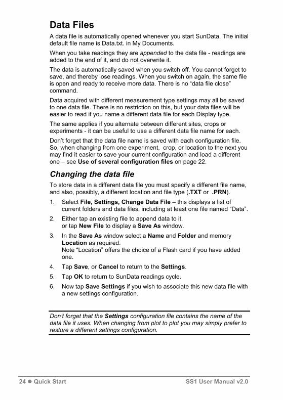
Data Files A data file is automatically opened whenever you start SunData. The initial default file name is Data.txt. in My Documents. When you take readings they are appended to the data file - readings are added to the end of it, and do not overwrite it. The data is automatically saved when you switch off. You cannot forget to save, and thereby lose readings. When you switch on again, the same file is open and ready to receive more data. There is no “data file close” command. Data acquired with different measurement type settings may all be saved to one data file. There is no restriction on this, but your data files will be easier to read if you name a different data file for each Display type. The same applies if you alternate between different sites, crops or experiments - it can be useful to use a different data file name for each. Don’t forget that the data file name is saved with each configuration file. So, when changing from one experiment, crop, or location to the next you may find it easier to save your current configuration and load a different one – see Use of several configuration files on page 22.
Changing the data file To store data in a different data file you must specify a different file name, and also, possibly, a different location and file type (.TXT or .PRN). 1. Select File, Settings, Change Data File – this displays a list of
current folders and data files, including at least one file named “Data”. 2. Either tap an existing file to append data to it,
or tap New File to display a Save As window. 3. In the Save As window select a Name and Folder and memory
Location as required. Note “Location” offers the choice of a Flash card if you have added one.
4. Tap Save, or Cancel to return to the Settings. 5. Tap OK to return to SunData readings cycle. 6. Now tap Save Settings if you wish to associate this new data file with
a new settings configuration.
Don’t forget that the Settings configuration file contains the name of the data file it uses. When changing from plot to plot you may simply prefer to restore a different settings configuration.
24 Quick Start SS1 User Manual v2.0
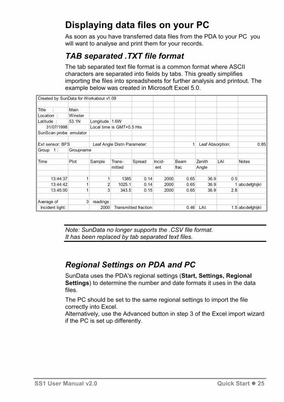
Displaying data files on your PC As soon as you have transferred data files from the PDA to your PC you will want to analyse and print them for your records.
TAB separated .TXT file format The tab separated text file format is a common format where ASCII characters are separated into fields by tabs. This greatly simplifies importing the files into spreadsheets for further analysis and printout. The example below was created in Microsoft Excel 5.0.
Created by SunData for Workabout v1.09
Title : MainLocation : WinsterLatitude : 53.1N Longitude 1.6W
31/07/1998 Local time is GMT+0.5 HrsSunScan probe emulator
Ext sensor: BFS Leaf Angle Distn Parameter: 1 Leaf Absorption: 0.85Group 1 : Groupname
Time Plot Sample Trans- Spread Incid- Beam Zenith LAI Notesmitted ent frac Angle
13:44:37 1 1 1385 0.14 2000 0.65 36.9 0.513:44:42 1 2 1025.1 0.14 2000 0.65 36.9 1 abcdefghijkl13:45:00 1 3 343.5 0.15 2000 0.65 36.9 2.8
Average of 3 readings Incident light: 2000 Transmitted fraction: 0.46 LAI: 1.5 abcdefghijkl
Note: SunData no longer supports the .CSV file format. It has been replaced by tab separated text files.
Regional Settings on PDA and PC SunData uses the PDA's regional settings (Start, Settings, Regional Settings) to determine the number and date formats it uses in the data files. The PC should be set to the same regional settings to import the file correctly into Excel. Alternatively, use the Advanced button in step 3 of the Excel import wizard if the PC is set up differently.
SS1 User Manual v2.0 Quick Start 25

The .PRN file format This format is designed for printing out directly, rather than importing into a spreadsheet. Choose the appropriate format when you create a new data file in File, Settings, SunScan. An example printout is shown below.
Created by SunData Title :Demonstration Location :Burwell, Cambridge Latitude :52.2N Longitude :0.4W 1996-05-19 Local time is GMT+1 Hrs SunScan probe emulator Ext sensor:BFS Leaf Angle Distn Parameter: 1.5 Leaf Absorption : 0.85 Group 1 :Presentation Time Plot Sample Trans- Spread Incid- Beam Zenith LAI Notes mitted ent frac Angle 15:51:12 1 1 270.9 0.13 2000.0 0.65 46.5 2.7 Notes appear here. 15:51:59 1 2 189.6 0.14 2000.0 0.65 46.6 3.2 15:52:08 1 3 1047.5 0.15 2000.0 0.65 46.6 0.8 15:52:16 1 4 63.4 0.14 2000.0 0.65 46.6 4.7 15:52:24 1 5 1225.3 0.15 2000.0 0.65 46.6 0.6 Average of 5 readings: Incident light: 2000.0 Transmitted fraction:0.28 LAI: 2.4
26 Quick Start SS1 User Manual v2.0

Menus and Screens
File menu options File Exit Exits the SunData program completely
(using the X in the top right corner only puts SunData into the background).
Save Settings
Choose an existing settings file to replace, or create a new one. You can select folders within ‘My Documents’, or on an expansion card if fitted. All the information in the File > Settings pages is saved.
Load Settings
Choose a previously saved settings file to load. Look at the File > Settings pages to check what settings have been changed.
Select a data file to view. Review Data
Select file
File Format Tab If Checked, the viewer lines up all the data values under the correct headings, and if ‘All’ 64 light readings are stored, shows these as a block of 4 x 16 readings. If not checked, the viewer shows the file with no adjustments.
File Start of File, End of File
Moves to the top or bottom of the file.
SS1 User Manual v2.0 Menus and Screens 27

Settings menu options No external SunScan is needed. The software will generate random values as if a SunScan probe were connected.
SunScan File > SunScan Connection
Emulator Settings
COM1 All the COM ports reported by your PDA are listed. Select the external serial port you have connected your SunScan to. This will usually be COM1. Select BFS if you have an external beam fraction sensor (e.g. BF3) connected to your SunScan.
External Sensor
None BFS
Choose an existing data file – new data will be appended to existing data, existing data will not be lost.
Data File Change Data File
New File Create a new data file. You can choose any folder within ‘My Documents’ or on an expansion card if fitted. Select ‘Tab separated’ if you will analyse your data using a spreadsheet program, and ‘Print’ if you want to print out the data files directly.
Set the leaf PAR absorption. 0.85 is typical.
Constants Leaf Absorption
0.5 to 1.0
Set the Ellipsoidal Leaf Angle Distribution Parameter, which describes the distribution of leaf angles within the canopy. 0 corresponds to entirely vertical leaf elements, 1 to a random spherical distribution, 1024 to entirely horizontal leaf elements. Use 1 as a default.
ELADP 0 to 1024
The name of the measurement site. Site Site name
The latitude of the measurement site, in degrees.
Latitude 0° – 90° North/South
The longitude of the measurement site, in degrees.
Longitude 0° - 360° East/West
Brings up the PDA Clock page. You can set your local time zone, date and time, or another that you are currently visiting. Daylight Saving Time is set automatically by the PDA for your selected time zone.
Set Time
Shows the current local time zone, and the difference between the local time and UTC (Universal Coordinated Time, or GMT). Use this to check that settings are correct.
Local Time
28 Menus and Screens SS1 User Manual v2.0

Values appropriate to canopy LAI measurements are displayed.
Display Settings Display type
LAI (cont’d) PAR Values appropriate to measurements
of PAR levels above and below the canopy are displayed.
All The display is the same as for PAR, but the 64 individual photodiode readings are also stored in the data file. A title for your experiment. This is stored along with site details, at the start of a block of readings.
Title
A group is a set of readings which all have the same settings. Groups are numbered automatically in the data file, but you can add a group name as well. A new group is started when the group name, or any other setting, is changed.
Group name
Within a group, readings are numbered incrementally by sample number, and plot number (1 – 256). Change these names if you prefer something different. Only the first 6 characters are displayed on screen, and in the Print format data file.
Sample name
As above. Plot name
SS1 User Manual v2.0 Menus and Screens 29

Utilities menu options Sets the individual sensors along the SunScan wand to match the reading of the connected BFS.
Utilities Calibrate Recalibrate SunScan
BFS must be connected by cable
Restores the calibration of the SunScan sensors that was determined at Delta-T.
Restore Factory Calibration
SunData will operate the SunScan unattended in whatever mode has been setup, and will take regular periodic readings. You may need to provide an external power supply for the PDA if you want to continue logging for many hours.
Autolog
When you want to start logging. You can set this a short time into the past, if you want to synchronise readings to the hour or day.
Start Date & time
When you want to stop logging. Must be in the future!
Stop Date & time
How often you want to take readings Minimum 00:00:01, maximum 23:59:59.
Read interval
hh:mm:ss
How often you want to average your readings. Should be a multiple of the read interval. Set to zero for no averaging.
Average interval
hh:mm:ss
If checked, SunData will stop taking readings during the night, and start again at dawn.
Ignore night time readings?
SunData will start taking readings according to the Autolog settings. The display will show a record of readings taken recently, and the time the next reading is due.
Start/Stop logging
If logging is in progress, this will stop logging, and return to the Autolog setup screen. Puts the PDA into sleep mode. It will wake up again briefly every time a reading is taken.
Sleep
This screen gives direct access to the SunScan via the serial port. It should only be used under instruction from Delta-T.
Comms Test
30 Menus and Screens SS1 User Manual v2.0

This screen calculates the sun’s position through a day. This can be useful in planning experiments.
Solar CalcUtilities (cont’d)
Default is today, but this can be set to any date.
Date
Initially set to the current Site, but can be set to any latitude & longitude.
Longitude & Latitude
Recalculates solar position after change of date or position.
Calculate
Gives version number for SunData, and SunScan firmware version and battery level, if connected.
About
SS1 User Manual v2.0 Menus and Screens 31

What to Measure and How
Experiment Design This section discusses the factors that bear on your experimental objectives. It should help you answer questions like:
• What equipment do I need?
• What readings must be taken?
• Will I have to wait for particular times of day or weather conditions? The type of study you propose to do will determine the time of year and duration of the experiment, and whether you are interested, for example, in monitoring growth by interception of solar radiation, or perhaps in the canopy structure as well. Some canopies types (the non-uniform ones) preclude the use of the SunScan’s direct LAI readout. You could, however, characterise the 3-dimensional light distribution within your canopy at different heights, or along transects through it. For brevity we call this approach “PAR mapping” in the discussion below. Answers to the above questions are complicated, but the following should give you a good appreciation of the main issues involved.
Above-canopy reference requirements This refers to measurements of PAR incident on the canopy, made at the same time as the below-canopy measurements. The question is whether to use a beam fraction sensor (BFS).
Use of a Beam Fraction Sensor e.g. BF3 Sunshine Sensor A BF3 connected to the SunScan probe provides the best option, because you can operate with fewest restrictions. However, with some canopy types this may not be practical. The next best option is to use the SunScan probe (without the BF3) sequentially above and below the canopy, but you may be restricted to times when the light levels are not changing fast.
Take LAI ReadingsSee also on page17.
32 What to Measure and How SS1 User Manual v2.0

Measuring Leaf Area Without a Beam Fraction Sensor This is the most complicated option. For an overview see Take LAI Readings on pages 17 & 18. Each LAI reading below the canopy requires a previous Incident reading and a Beam Fraction reading above the canopy. If measuring LAI without a Beam Fraction Sensor, SunData ensures you first measure Beam Fraction at least once. (This provides both the Incident Total and incident Diffuse radiation readings.) For second and subsequent readings it is appropriate to just check the Incident total above the canopy, which is quicker. SunData does not insist you take more Beam Fraction readings, though you may do so if you wish.
If measuring LAI without a Beam Fraction Sensor, SunData ensures you first measure Beam Fraction at least once.
Beam Fraction measured already?
YES
NO
Read Average
Measuring Incident Radiation Hold the probe level above the canopy for this reading.
Measuring Beam fraction Hold the probe level above the canopy as before, but now cast a small shadow from greater than 50 cm above the probe to shade 5 to 25cm of
SS1 User Manual v2.0 What to Measure and How 33

the probe. Don't hold the shade too close to the probe - otherwise it will cut out some of the diffuse light as well. SunData looks at the readings from the photodiodes and uses the lowest value to calculate the Diffuse component of the incident light. It uses the highest photodiode values to calculate the incident Total, and uses these two values to calculate and display the Beam Fraction:
The Beam Fraction reading is used to increase the accuracy of the calculation of Leaf Area Index, as explained in the LAI Theory section. However, this is a secondary effect, and you should not worry unduly about the second decimal place for the Beam Fraction value.
Direct and Diffuse components Assuming that you make your above-canopy measurements on the SunScan (with or without a BF3), then the next table summarises whether you need to measure the Direct and Diffuse components of the incident light.
Type of study Incident PAR Total only
Incident PAR Direct & Diffuse components
Fractional interception Yes No LAI No Yes PAR mapping Yes Possibly
Canopy type and BF3 practicalities Canopy type is the next variable to be considered. As a general guide, the above-canopy reference measurements should be made close to, or above, the position of the SunScan probe.
Canopy type Options Comments
Radio link is generally best, long cables need management
Low BF3 connected, with extension cables or radio link
Low No BF3 Slower. Needs slow-changing light conditions. Good when possible High Devise a portable BF3
mount. Use extension cables or radio link
Needs steady light conditions. Clearing light may be partly shaded
High Use clearings to get out from under the canopy. (No BF3 required)
High Use independent sensor for above canopy PAR
Needs slow-changing light, and possibly time average readings. LAI readings not available
34 What to Measure and How SS1 User Manual v2.0

Canopy type and LAI estimates Some types of canopy do not conform well to the assumptions about canopy structure used by the SunScan in calculating LAI. The following table will give you an initial idea of whether it is applicable to your canopy. You should read the chapter on the LAI theory for a fuller appreciation of the subject. Some guidance on specifying values for the typical leaf angle (the ELADP parameter) and leaf absorptivity of your canopy comes later in this section.
Canopy type Comments Low, uniform (e.g. cereal crops, trial plots)
Good for LAI
Low, regular but not uniform (e.g. row crops)
Absolute LAI dubious. May show valid trends. PAR mapping
Isolated trees or bushes (e.g. orchard trees)
PAR mapping only
sparse vegetation (e.g. scrub) PAR mapping only high, uniform , not clumped (e.g. some timber plantations)
In principle good for LAI, but practical difficulties for above-canopy reference
high, clumped vegetation (e.g. natural woodland)
PAR mapping only
Canopy Sampling volume It is useful to be aware of the volume of the canopy that the SunScan is "seeing" when calculating LAI, so you can take this into account when planning your sampling scheme. With the Direct beam, the SunScan only sees the canopy elements along a thin 1 metre wide sheet between the probe and the sun. With Diffuse light, the SunScan sees a much larger volume, covering a region centred on the probe, extending out approximately as far as the canopy is high, but with the canopy above the probe making the greatest contribution. These two very different sampling volumes are measured in the same proportions as the incident Direct and Diffuse light. This means that in strong sun (high Beam Fraction) the canopy volume sampled is fairly small and well defined. As the Beam Fraction decreases, the volume sampled increases, and has less well defined limits.
SS1 User Manual v2.0 What to Measure and How 35
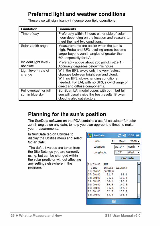
Preferred light and weather conditions These also will significantly influence your field operations.
Limitation Comments Time of day Preferably within 3 hours either side of solar
noon depending on the location and season, to meet the next two conditions.
Solar zenith angle Measurements are easier when the sun is high. Probe and BF3 levelling errors become larger beyond zenith angles of greater than 60°, especially for LAI.
Incident light level - absolute
Preferably above about 200 μmol.m-2.s-1. Accuracy degrades below this figure.
Light level - rate of change
With the BF3, avoid only the very fastest changes between bright sun and cloud. With no BF3: slow-changing conditions needed. For LAI, with no BF3, slow change of direct and diffuse components.
Full overcast, or full sun in blue sky
SunScan LAI model copes with both, but full sun will usually give the best results. Broken cloud is also satisfactory.
Planning for the sun’s position The SunData software on the PDA contains a useful calculator for solar zenith angles on any date, to help you plan appropriate times to make your measurements. In SunData tap on Utilities to display the Utilities menu and select Solar Calc. The default values are taken from the Site Settings you are currently using, but can be changed within the solar predictor without affecting any settings elsewhere in the program.
36 What to Measure and How SS1 User Manual v2.0
Advice on Absorption and ELADP values Absorption Absorption is the percentage of incident PAR absorbed by the leaf.
Most leaves have Absorption values in the range 0.8 - 0.9, so the default value of 0.85 will usually be appropriate.
Only adjust the Absorption value if you have good reason to, e.g. if working with very thick, dark leaves, or very thin transparent ones. If you set the Absorption value to 1.0, the LAI calculations will be equivalent to simpler models that assume completely black leaves.
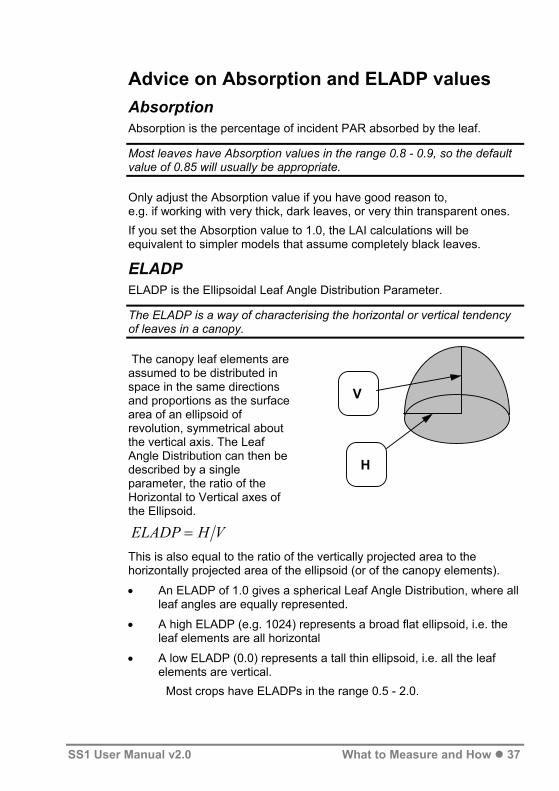
ELADP ELADP is the Ellipsoidal Leaf Angle Distribution Parameter.
The ELADP is a way of characterising the horizontal or vertical tendency of leaves in a canopy.
V
H
The canopy leaf elements are assumed to be distributed in space in the same directions and proportions as the surface area of an ellipsoid of revolution, symmetrical about the vertical axis. The Leaf Angle Distribution can thedescribed by a single parameter, the ratio of the Horizontal to Vertical axes of the Ellipsoid.
n be
ELADP H V=
This is also equal to the ratio of the vertically projected area to the horizontally projected area of the ellipsoid (or of the canopy elements).
• An ELADP of 1.0 gives a spherical Leaf Angle Distribution, where all leaf angles are equally represented.
• A high ELADP (e.g. 1024) represents a broad flat ellipsoid, i.e. the leaf elements are all horizontal
• A low ELADP (0.0) represents a tall thin ellipsoid, i.e. all the leaf elements are vertical.
Most crops have ELADPs in the range 0.5 - 2.0.
SS1 User Manual v2.0 What to Measure and How 37

Setting ELADP
The default setting of 1.0 (spherical leaf angle distribution) is a good starting point.
If you are unable to estimate the ELADP any other way, set ELADP to 1.0. You can check how much this affects your results in the field by making several measurements in one place within a canopy using different ELADP values, and comparing the LAI values calculated.
Estimating ELADP in the field If the canopy shows a clear predominance of horizontal or vertical leaves, then choose a small volume of the canopy that is representative. Count the number of leaves that are at more than 45° from the vertical (i.e. mostly horizontal), and the number of leaves that are less than 45° from the vertical. If the leaves are curved, pick the angle at the widest part of the leaf. The ELADP can be estimated as the number of horizontal leaves (N ) divided by the number of vertical leaves (Nh v), multiplied by π/2 (1.6).
ELADP NN
h
v=
π2
The factor π/2 comes from the fact that the vertical leaves are distributed about the vertical axis, so for any light ray, some will be seen face-on, and some edge-on. In effect, the ellipsoidal distribution is being further approximated as a cylindrical distribution.
If you set ELADP to 1024, and Absorption to 1.0, the LAI calculations will be equivalent to the simple Beer’s law inversion based on black, horizontal leaves.
38 What to Measure and How SS1 User Manual v2.0

Relationship between Mean Leaf Angle and ELADP Wang & Jarvis (1988) describe the relationship between ELADP and the Mean Leaf Angle, which is sometimes known from other studies. Their results are summarised by the following graph:
90
80
70
60
50
40
30
20
10
00.01 0.1 1
Typical ELADP Values (from Campbell and van Evert, 1994)
Crop ELADP Crop ELADP Ryegrass 0.67-2.47 Cucumber 2.17
Maize 0.76-2.52 Tobacco 1.29-2.47
Rye 0.8-1.27 Potato 1.70-2.47
Wheat 0.96 Horse Bean 1.81-4.1
Barley 1.20 Sunflower 1.81-4.1
Timothy 1.13 White clover 2.47-3.26
Sorghum 1.43 Strawberry 3.03
Lucerne 1.54 Soybean 0.81
Hybrid Swede 1.29-1.81 Maize 1.37
Sugar beet 1.46-1.88 J. Artichoke 2.16
Rape 1.92-2.13
10 100
ELADP
MLA
deg
rees
SS1 User Manual v2.0 What to Measure and How 39

SunScan Measurement modes Having designed your experiment, choose which data collection option best suites your experiment, and whether you need a BF3 sensor. If used with a PDA running the SunData software, SunScan has three measurement modes: LAI, PAR or ALL. Each can be used with or without a BF3 connected. It can be operated manually, or automatically via the Autolog utility. If used with a stand alone analogue data logger, SunScan acts as a simple line quantum sensor with only one analogue output, representing transmitted PAR. See also: Experiment Design on page 32.
40 What to Measure and How SS1 User Manual v2.0

LAI, PAR and All - measurement modes (Note: the values on the screens below, generated by the Emulator, are for illustration and may not be very realistic).
LAI Readings With BFS Without BFS
With BFS Without BFS
With BFS Without BFS
Note: LAI readings are only available in this mode.
PAR Readings Average transmitted PAR, and the spread in individual photodiode PAR readings.
ALL Readings Display is the same as for PAR, but data file also contains all the individual readings.
SS1 User Manual v2.0 What to Measure and How 41

Automatic logging modes Autolog mode: SunScan can be logged automatically from the PDA via the SunData Utilities, Auto log function. With Autolog you can operate SunScan automatically in any of its modes, just as if you were pushing the read, store and average buttons at regular intervals. See also : Appendix A. Logging the probe as a Linear Quantum Sensor on page 74.
Tap on a time field, and then on the arrow(s) to change them
You are prompted with a current Start time and date, and 6 hours later a stop time. Edit these appropriately
Change the Read Interval to whatever sampling interval you want (hh:mm:ss)
If you leave the Average Interval at 0 you will not get average summaries. Any other setting (hh:mm:ss) will insert average summaries into the data file at the specified intervals
Night time is defined as when the sun is more than 6° below the horizon. Sunscan computes this for you automatically.
The Autolog setup screen
Tap on a date field to change it
14
The Start time can be set to a time up to 24 hours before the current time! You might do this, say, if you wanted to set up averaging on the hour with sampling every minute but the system time had just gone past the hour.
Start Logging
Selecting Start logging displays a summary of the logging progress as shown.
Selecting Sleep puts the PDA into a low power state between readings.
42 What to Measure and How SS1 User Manual v2.0

Measurement procedures in the field Check the equipment a day or two before your field experiment for routine matters such as the state of the batteries and the internal desiccant. See the Technical Reference section on page 62 for details of these.
Probe handling in the field GO Button Use of the red button on the probe handle lets you take and store readings without needing to look at the PDA. The beeps tell you where you are. Beeps • 1 beep:- Read
• 2 beeps:- Store To turn the beeps on or off select Start, Settings, Sounds & Notifications.
Levelling the probe The probe is fitted with a miniature bubble level to help you hold it level during the measurements.
In most situations under a canopy, exact levelling is not critical.
Try to minimise your own shading of the probe when taking readings. If the probe can "see" you, you will be blocking a certain amount of diffuse light from the sky. Casting a dense shadow on the probe by blocking the direct beam could cause significant errors. Your best strategy will be to take as many samples as quickly as you can rather than aim for perfection with each reading. This will counter the spatial variability of most canopies, and is especially true if you have to work in unsteady light conditions.
When using the GO button, concentrate on getting the best levelling for the Read function (single beep) which then "freezes" the reading. It does not matter whether the probe is level when you press GO the second time to Store the reading.
Levelling is most critical when you are using the probe:
• for the incident radiation above the canopy, and
• when the direct solar beam is strong, and
• when the sun is low in the sky.
SS1 User Manual v2.0 What to Measure and How 43

Use of the tripod The probe base has a standard camera mount socket for use with the tripod. You will probably not want to use this routinely, but you could use it, for example, to mount the probe in one fixed position for taking readings in the Autolog mode during the course of a day.
PDA Straps and Belts In use the PDA is always connected to the SunScan via a curly cable, and both your hands are full.
Elastic Hand strap An elastic strap provided as standard with each Recon PDA helps secure it in your hand. This and a large pocket, may meet all your needs.
Protective Case type SS-PC1 Each Recon supplied by Delta T includes a carry case including a removable screen protection flap, an adjustable hand strap, a removable belt clip and a simple neck lanyard. Note 1: The Belt clip may be left on your belt for docking the PDA when not in use. Unlike the Sacci belt PDA holder below, the PDA screen cannot easily be seen when clipped to your belt Note 2: Remove this belt clip when using this with the SS-HB1 Holster Belt
Holster Belt for PDA and SunScan Probe type SS-HB1 This optional belt has a sliding holster for the PDA and a simple docking cradle for SunScan.
Both PDA and SunScan can be quickly parked in their holsters, permitting two-handed annotation of readings and hands-free travel between measurements – unless you have a BF3 and tripod and cable attached as well!
44 What to Measure and How SS1 User Manual v2.0

Beam Fraction Sensor Handling in the Field The Beam Fraction sensor is definitely recommended for taking most types of readings, however the extra cable connection to the standard SunScan probe does add an unwelcome practical complication! Use of the BF3 radio link may be preferable See also SunScan System Radio Link User Manual
Using the tripod The BF3 has a tripod mount, which will probably be the most convenient mounting method to use above low field canopies (up to about 1.8 m high). If you are working with canopies higher than this, you will need to devise an alternative mounting method.
Levelling the BF3 The BF3 is equipped with a miniature bubble level. The tripod supplied has 3-axis adjustment to facilitate levelling. It is more important to level the BF3 accurately than the probe.
Extension cables, and the location of the BF3 Extension cables of 10, 25 and 50 m can be fitted between the BF3 and the probe, which will extend your range of operation from the BF3. There is a trade-off between range and convenience: the greater your range, the fewer times you need to re-site the BF3, but the more time you are likely to spend handling the cable. Extension cables can be joined together. A combination of two shorter cables may be preferable to one long one.
If connected by cable SunScan will read the BF3 and probe simultaneously.
If the different locations are widely spaced apart, the light levels could momentarily be different - cloud shadows can easily travel at 20 m.s-1. If connected by radio the BF3 signal is read up to 3 seconds before the probe reading is made.
The solution is to be aware of this in fast changing conditions and avoid taking readings at critical moments. Very long cable lengths may introduce a small systematic error in BF3 readings. Up to 100 metres, this should not be significant (< 10 μmol.m-2.s-1). At 200 metres it could add about 20 μmol.m-2.s-1 to the readings, which may need subsequent adjustment .
SS1 User Manual v2.0 What to Measure and How 45

PAR calibrations
This section describes the basis for the light calibrations used in the SunScan system, and explains when and how you might want to recalibrate the probe or restore its factory calibration.
Factory light calibration The SunScan probe and Beam Fraction Sensor are calibrated to give PAR readings which match those of a standard PAR quantum sensor in typical bright daylight conditions. This matching cannot be made completely reproducible because an ideal PAR quantum sensor has perfect spectral and cosine responses whereas the SunScan probe and BF3 can only approximate to the ideal. However, for most normal usage, the SunScan calibration will be perfectly satisfactory, but if you are working under strong artificial lights (for example) you may need to contact Delta-T for advice.
SunScan readings of LAI and fractional interception depend for their validity on the ratio of the transmitted light to the incident light rather than their absolute values, so it is the matching between the probe and the BF3 calibration that is important.
Checking the probe/BF3 matching It is good experimental practice to carry out this test in the field before (and after) taking a lot of readings.
• Mount the SunScan probe and your BF3 horizontally in uniform sunlight. Make sure the probe and BF3 dome is clean.
• In the SunData program, select the PAR display and take some readings.
The display will show you the values of the SunScan probe, BF3 Total and BF3 Diffuse readings. The SunScan and BF3 Total values should be approximately the same. Store these readings, and you will have complete results that you can refer back to later if needed.
The probe and BF3 Total readings may be within 5-10% of each other without greatly contributing to errors in canopies where the transmission is below 50%.
Errors from the mismatch are likely to be swamped by the magnitude of the variation in the samples. However, if you want to improve the matching, then proceed with the Recalibrate option. The Recalibrate option This option matches your probe to your BF3 (you cannot recalibrate the probe if you do not have a BF3).
46 What to Measure and How SS1 User Manual v2.0
• Set up the probe and BF3 as for the previous test.
• In SunData on the PDA select Utilities, Calibrate, Recalibrate SunScan, then follow the instructions.
You should not expect to have to do this very often. The photodiodes and light measurement circuits are very stable.
The sources of the apparent variability mentioned above, between the probe and BFS, are
• the not quite ideal cosine and spectral responses of the sensors
• any dirt and grime that builds up on the on the SunScan diffuser (so keep it clean).
You cannot recalibrate the probe when using the radio link. (The function is disallowed because the light levels may not be the same.) Restoring the factory calibration At any time after carrying out the Recalibrate option you can restore the original factory calibration. You do not have to set up the probe or BF3 in uniform light.
• In SunData on the PDA Select Utilities, Calibrate, Restore Factory Calibration.
You will briefly see a message confirming that this has been done.
Comparing the calibration with other PAR sensors You can carry out matching comparisons between the probe and BF3 and any other PAR quantum sensor. You cannot reset the probe values to it, but you can annotate the readings and retain the comparison information in the SunScan data files.
The "Spread" measurement The "Spread" value is a measure of the relative variation of the light along the probe. This is a useful parameter in light profiling measurements: it is the value of the standard deviation of the 64 photodiode readings, divided by their mean.
You can check the probe uniformity of calibration at any time by taking a reading in uniform light. The spread value should be 0.00 or 0.01.
SS1 User Manual v2.0 What to Measure and How 47

Environmental and moisture protection You should be aware of the different levels of protection of the components of the SunScan system to avoid putting them at risk when working outdoors. As with all field instruments you should minimise, as far as practical their exposure to high or rapidly changing temperatures.
The SunScan probe and Beam Fraction Sensor
Warning! The probe and BF3 are designed to resist dust and water jets (IP65), but they are not hermetically sealed. They will survive rainfall, but will not survive being immersed in water.
Avoid any situation where they could be flooded. Internal condensation will be avoided provided that you keep the desiccant fresh. Inspect the coloured indicator panels on the housings to check this. The probe and BF3 are reasonably robust, but they do not have a drop test rating. Do not drop them! Take extra care when carrying the 1 metre-long probe!
The Recon PDA The Recon is extremely rugged, sealed to IP67, that is sealed against accidental immersion (submersible to 1 meter for 30 minutes). For details see the impressive environmental specifications listed in the Recon Getting Started Guide. The weakest link may be the 9 pin serial connector on the SunScan cable, which is not sealed .
Warning! If you leave the Recon in the field for Autologging, we recommend you seal it in a bag or container with, say, 25g of desiccant (to protect the SunScan serial connector from moisture).
48 What to Measure and How SS1 User Manual v2.0

LAI theory
In this section we shall explain as fully as we can how the SunScan computes its readings of leaf area index, and what the main limitations and provisos are in interpreting these for real canopies.
Ingredients of the LAI computation method There are three broad areas contributing to the final result.
Geometric analysis The first is the analysis of what happens to a ray of light passing through the canopy. In order to do this, we have to make some general assumptions about the canopy, i.e. uniformity, randomness and total absorption by canopy elements. This was done by Campbell (1986) for a beam of light from a single direction (the Direct solar beam) passing through a canopy with a generalised ellipsoidal leaf angle distribution function. This function allows a wide range of different canopy types to be described by the value of a single parameter ELADP. Wood then integrated Campbell’s result over the whole sky to give a description of the transmission of Diffuse light through the same canopy. This is important because the transmission of Diffuse light is different, and in reality there is usually a combination of both Direct and Diffuse illumination. In particular, the analysis shows that Diffuse transmission is strongly dependent on the leaf angle distribution, a point which has not generally been recognised. These functions are integrals which do not have direct analytical solutions, so have to be solved numerically, and computable functions fitted to the results. This has been done to a high degree of accuracy, improving on Campbell’s original approximation.
Incomplete absorption - more elaborate analysis The above analysis based on black leaves is relatively straightforward. However, real leaves also reflect or scatter some of the light that falls on them. Typically, only about 85% of the incident light is absorbed. This means that in reality, every leaf element in the canopy is re-emitting light, as well as absorbing it, which makes the situation much more complicated. Because the direction of any particular light ray can be changed by reflection or scattering, it means the spatial distribution of the light changes through the canopy. Therefore it is no longer adequate to consider just the vertical component of the light (as measured by a cosine corrected sensor), the horizontal component must also be included. This is why Wood’s analysis also considers a hemispherical response sensor (which measures both horizontal and vertical components).
SS1 User Manual v2.0 LAI theory 49

The relentless advance of computing power has made it possible to model the situation in ways that were not feasible in the past. By integrating the "black leaf" analysis into a computer model Wood has calculated the light levels in the canopy across the whole range of canopy and incident light parameters.
Equation fitting and inversion The results of the computer modelling, while accurate, are not suitable for use in a field instrument. It takes many minutes of processing on a fast PC to calculate light transmission for any given conditions using the model, and the earlier data collection terminal previously supplied with SunScan was not a fast computer!. The model calculates values of light transmission for a given LAI, whereas the SunScan measures light transmission. This means that the functions have to be inverted to work back to LAI, which is more difficult. To give you immediate results in the field, computable functions have been fitted to the model data, and it is these that are solved to give LAI to reasonable accuracy from the parameters measured by the SunScan system.
Note! Wood’s SunScan equations are copyright, and you should not copy them without written permission unless for purposes of scientific debate or publication, in which case they should be fully acknowledged.
Theory versus reality We believe that Wood’s SunScan equations accurately reflect the assumptions that the modelling is based on. By far the largest uncertainties are bound to be caused by
• the mismatch between the real canopy architecture and the simplifying assumptions built into the fundamental analysis
• to a lesser extent the uncertainty in the numerical values of ELADP estimated for your canopy.
With these caveats, the values of LAI for your canopy, even if of uncertain accuracy, will provide valid trends for a given canopy (e.g. canopy growth in a season), and valid comparisons between different canopies of similar architecture (e.g. trial plots of different cultivars of the same species). If you are able to compare SunScan estimates with actual harvested samples from time to time, this will enable you to calibrate out any systematic errors due to your canopy not matching the SunScan assumptions.
If you wish, you can force the SunScan calculations to be equivalent to older, less sophisticated inversions by setting some of the parameters to appropriate values. For example, setting ELADP to 1024 (horizontal leaves) and Absorption to 1.0 will give you the simple Beer’s law inversion.
50 LAI theory SS1 User Manual v2.0
Derivation of Wood’s SunScan canopy analysis equations
The major assumptions • The canopy is an infinite, uniform, horizontal slab, with leaf elements
randomly distributed in proportion to the surface area of an ellipsoid, as described by Campbell.
• The incident light consists of a component from a point source at a given zenith angle (the Direct beam); and a Diffuse component of equal intensity from every point in the sky (Uniform Overcast Sky).
• The canopy either has sufficiently high LAI that light reflected back from the ground below is negligible, or the reflectance of the ground is similar to that of the canopy.
• Of the light intercepted by the leaf element, a fraction a (absorption) is totally absorbed. The remainder is re-emitted uniformly in all directions.
Beer's law for canopy absorption Beer's law occurs in many situations where events happen at random. In the case of light absorption by a canopy, it applies to the absorption of incident photons or light rays. For a uniform infinite randomly distributed canopy of completely absorbing leaves, it can be shown that the relationship between the transmitted light I, a beam of incident light I0 and the Leaf Area Index L is given by:
where K is the extinction coefficient which depends on the leaf angle distribution and the direction of the beam. K=1 for entirely horizontal leaves.
Campbell's Ellipsoidal LAD equations. Campbell (1986) derives an equation for the extinction coefficient of leaves distributed in the same proportions and orientation as the surface of an ellipsoid of revolution, symmetrical about a vertical axis. The semi vertical axis is a and the semi horizontal axis is b . There is symmetry about the vertical axis. He relates these to a single parameter x = b/a. (x is the Ellipsoidal Leaf Angle Distribution Parameter, or ELADP). The extinction coefficient also depends on the zenith angle of the incoming direct beam. Canopy elements are assumed to be completely black, and randomly distributed in a horizontal slab extending to infinity in all directions.
I .I 0 exp( . )K L
SS1 User Manual v2.0 LAI theory 51

Note: in the following equations derived in MathCAD, different conventions are used for some symbols. Equality is represented by :=, and tan2 (θ) is expressed tan(θ)2 .
The extinction coefficient, K, is calculated as follows:
x2 tan( )θ2
K( ),x θ0.708x .1.702 ( )x 1.12
Where: x is the ELADP θ is the zenith angle of the direct beam.
3
2
1
0
K( ),0 θ
K( ),1 θ
K( ),100 θ
θ
The transmitted fraction of incident direct light is given by:
τ dir exp( ).K( ),x θ L
where L is the canopy LAI.
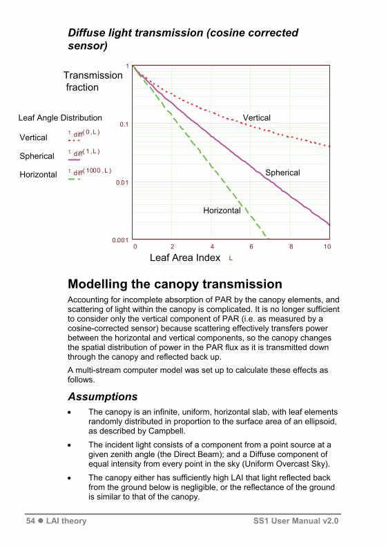
Transmission of Diffuse Light Campbell's analysis applies only to a beam of light from a specific direction, which is the Direct solar beam in our case. Even under strong sunlight, the Direct fraction rarely exceeds 80% of the Total incident radiation, so penetration of the Diffuse component of incident radiation is also important. There is a misconception that the extinction coefficient for Diffuse light is independent of canopy Leaf Angle Distribution, but this is not the case as the following analysis shows. As the following graph also shows, transmission of Diffuse light does not obey a simple Beer's law curve, so cannot be represented by a single extinction coefficient, except in the case of a horizontal LAD.
52 LAI theory SS1 User Manual v2.0

The next section derives the transmission of light from a uniform overcast sky through a uniform infinite canopy of black leaves of constant LAI with an ellipsoidal leaf angle distribution.
Let the sky have uniform brightness of 1 per steradian over the hemisphere. The radiance of a strip around the sky at angle θ is given by:
R ...2 π sin( )θ dθ and the irradiance on a horizontal surface due to that strip is given by:
I 0....2 π sin( )θ cos( )θ dθ
The total irradiance due to the hemisphere is obtained by integrating over the complete sky area:
For each strip of sky, the transmitted radiation is given by
where K is the extinction coefficient from Campbell, so the total transmitted radiation is
and the transmission fraction τ is given by I/I0
τ diff( ),x L .1π
d0
π
2θ....2 π sin( )θ cos ( )θ exp( ).K( ),x θ L
=
This integral was evaluated numerically over the range x = 0 to 1000 and L = 0 to 10, and is graphed below for three different values of x.
d0
π
2θ...2 π sin( )θ cos( )θ 1 π
I .I 0 exp( . )K L
I d0
π
2....2 π sin( )θ cos ( )θ exp( ).K( ),x θ L θ
SS1 User Manual v2.0 LAI theory 53
Diffuse light transmission (cosine corrected sensor)
1
0.1
0.01
0.0010 2 4
Modelling the canopy transmission Accounting for incomplete absorption of PAR by the canopy elements, and scattering of light within the canopy is complicated. It is no longer sufficient to consider only the vertical component of PAR (i.e. as measured by a cosine-corrected sensor) because scattering effectively transfers power between the horizontal and vertical components, so the canopy changes the spatial distribution of power in the PAR flux as it is transmitted down through the canopy and reflected back up. A multi-stream computer model was set up to calculate these effects as follows.
Assumptions • The canopy is an infinite, uniform, horizontal slab, with leaf elements
randomly distributed in proportion to the surface area of an ellipsoid, as described by Campbell.
• The incident light consists of a component from a point source at a given zenith angle (the Direct Beam); and a Diffuse component of equal intensity from every point in the sky (Uniform Overcast Sky).
• The canopy either has sufficiently high LAI that light reflected back from the ground below is negligible, or the reflectance of the ground is similar to that of the canopy.
6 8 10
τ diff( ),0 L
τ diff( ),1 L
τ diff( ),1000 L
LLeaf Area Index
Transmission fraction
Leaf Angle Distribution
Vertical
Spherical
Horizontal
Vertical
Spherical
Horizontal
54 LAI theory SS1 User Manual v2.0

• Of the light intercepted by the leaf element, a fraction a (absorption) is totally absorbed. The remainder is re-emitted uniformly in all directions.
In detail: • The canopy is divided into horizontal layers of LAI 0.1
• Direct beam absorption by each layer is calculated using Campbell's equation. In calculating the amount of absorbed light that is re-emitted, the total power in the direct beam has to be used (i.e. as measured by an integrating hemisphere or a cosine-corrected sensor perpendicular to the beam). The amount intercepted by the layer is the difference between the absolute intensity above and below the layer.
• Diffuse light intercepted by the layer is calculated in a similar way, taking into account the incident Diffuse light, and the sum of re-emitted light from all other layers, attenuated by the intervening layers. This is done for both down welling and upwelling Diffuse light. A fraction of the Diffuse light absorbed by the layer is also re-emitted. Again, absolute rather than cosine-corrected intensity measurements must be used.
• Both cosine-corrected and absolute light measurements are calculated for each layer, and the model iterated until it converges. This has been done for a range of different values of zenith angle, Direct/Diffuse ratios, Leaf Angle Distributions and Absorptions.
Simpler functions have been found to approximate these results, and are used in the SunData software when inverting transmitted fraction back to LAI. These are described in detail in the next section.
The canopy model
Direct solar beam
Upwelling scattered light
DiffuseLight
Canopy layerL = 0.1Absorption = aELADP = x
Direct beam scattered
Attenuated Direct beam
Downwelling Diffuse and
scattered light
Diffuse light scattered
Zenith angle
SS1 User Manual v2.0 LAI theory 55

Accuracy of LAI calculations When used to predict LAI from transmitted fraction, the functions used in the SunData software are accurate to within ±10% ±0.1 over the range of LAI less than 10 and Zenith Angle less than 60° when compared to the output of the full model.
The errors become larger for highly vertical leaves with a strong low sun, and users should avoid these conditions if possible.
In practice, the greatest errors are likely to follow from the differences between the real canopy and the idealised assumptions in the model.
56 LAI theory SS1 User Manual v2.0
Functions used to model canopy transmission
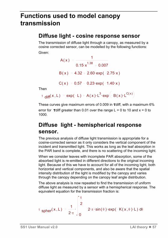
Diffuse light - cosine response sensor The transmission of diffuse light through a canopy, as measured by a cosine corrected sensor, can be modelled by the following functions: Given:
1 A( )x .0.15 x1.38 0.007 Then
These curves give maximum errors of 0.009 in τdiff, with a maximum 6% error for τdiff greater than 0.01 over the range L = 0 to 10 and x = 0 to 1000.
Diffuse light - hemispherical response sensor. The previous analysis of diffuse light transmission is appropriate for a cosine-corrected sensor as it only considers the vertical component of the incident and transmitted light. This works as long as the leaf absorption in the PAR band is complete, and there is no scattering of the incoming light. When we consider leaves with incomplete PAR absorption, some of the absorbed light is re-emitted in different directions to the original incoming light. Because of this we have to account for all of the incoming light, both horizontal and vertical components, and also be aware that the spatial intensity distribution of the light is modified by the canopy and varies through the canopy depending on the canopy leaf angle distribution. The above analysis is now repeated to find the transmission of uniform diffuse light as measured by a sensor with a hemispherical response. The equivalent equation for the transmission fraction is:
B( )x 4.32 .2.60 exp( ).2.75 x
C( )x 0.57 .0.23 exp( ).1.40 x
τ diff( ),x L exp( )L ..A( )x L3 exp .B( )x LC( )x
τ spher( ),x L .1.2 π
d0
π
2...2 π sin( )θ exp ). θ( K( ),x θ L
SS1 User Manual v2.0 LAI theory 57

This was again calculated numerically and curves fitted to the data with similar accuracy as above. The curves fitted are:
P( )x 1 ..0.4 exp( ).0.1 x ( )atan( ).0.9 x 0.95Given:
Q( )x .0.255 atan( )x 0.6
R( )x exp( )x
τ spher( ),x L exp
LQ( )x .R( )x ln( ).P( )x 1 L
Diffuse light transmission (hemispherical response sensor)
Leaf Area Index
Transmission fraction
Leaf Angle Distribution
Vertical
Spherical
Horizontal
Vertical
Spherical
Horizontal
1
0.1
0.01
0.0010 2 4 6 8 10
τ spher( ),0 L
τ spher( ),1 L
τ spher( ),1000 L
L
58 LAI theory SS1 User Manual v2.0

Modelling incomplete PAR absorption and scattering Radiation models have been used for many years to calculate the effects of scattering in the canopy e.g. Norman & Jarvis (1975). Wood's model incorporates Campbell’s ellipsoidal leaf angle distribution and the effects this has on transmission of both Direct and Diffuse light. The model splits the canopy into layers of LAI 0.1, extending to a sufficient depth to absorb all of the incident light. Incident light above the top layer was a known fraction of Direct (at a given zenith angle) and Diffuse light. The amount of light absorbed by a layer, assuming completely black leaves, was calculated. The fraction of this absorbed light re-emitted by the leaves was then assumed to be re-emitted in all directions uniformly (see Monteith & Unsworth, 1990, p85 onwards) . The light level at any point in the canopy is then calculated assuming complete absorption, plus the sum of the light re-emitted by each canopy layer, attenuated by the intervening layers. These calculations had to take full account of both horizontal and vertical light components. This involved an iterative solution and a lot of computer time. Finally, the light intensity as measured by a cosine corrected sensor was calculated. The results were then analysed in terms of La, the LAI of a canopy of black leaves that would give the same transmission as a canopy of LAI L assuming incomplete absorption, all other factors being equal.
L is the "true" LAI, La is the LAI that when used in the black leaf model, gives the same transmission as L used in the complete model. a is the leaf absorptivity in the PAR band. The function g varied with all the other parameters in a complex way, but most strongly with x, the leaf angle distribution parameter, and with solar zenith angle for the direct beam. The following equations represent quite a crude approximation to the full model, but give satisfactory results for most situations. If any given transmission fraction is inverted using the approximation, the LAI calculated is within ±10% ±0.1 of the "true" LAI indicated by the full model, except for x near 0 (extreme vertical leaves) and zenith angle > 60° (strong low sun). For diffuse light:
For direct beam: where: x is the ellipsoidal leaf angle distribution parameter zen is the solar zenith angle in radians.
L a.L ( )1 g( )1 a
g diff 0.5
g dir 0. .0.7 ze .0.2 zen52 n2 0.exp( ). .1.5 x 3
SS1 User Manual v2.0 LAI theory 59

The full equation thus becomes:
This looks hard to invert to get LAI from τ, but an iterative solution is fairly straightforward given the computing power, and is much simpler than the full numerical solution.
Calculating zenith angles Zenith angles are calculated from latitude, longitude, and local time using standard astronomical equations as given in Practical Astronomy. These give zenith angles accurate to better than 0.1° and times of sunrise or sunset to within a few seconds.
Summary A computer model has been created which calculates accurately the transmitted light below the canopy based on the assumptions given. This has been run over the whole range of each of the different variables, i.e. Direct beam angle, Direct beam fraction, Leaf Angle Distribution, Leaf Absorption and Leaf Area Index. The results of these runs, taking many hours of computer time, have been collected and functions found to fit them. These approximating functions are used in the SunData software to predict LAI from the measured inputs in the field. The LAI values calculated by the SunData software are within ± 10% ± 0.1 of the LAI that would have been calculated by the full model.
τ
+
....f b exp ..K( ),x θ 1 .g dir ( ) Direct 1 a L
.1 f b exp L a..A( )x L a
3 exp .B( )x L aC( )x Diffuse
60 LAI theory SS1 User Manual v2.0

Scientific references Campbell G S (1986). Extinction coefficients for radiation in plant canopies using an ellipsoidal inclination angle distribution. Agric. For. Meteor., 36:317-321. Campbell G S and F K van Evert (1994) Light interception by plant canopies: efficiency and architecture. In J L Monteith, R K Scott, and M H Unsworth, Resource Capture by Crops, Nottingham University Press. Campbell G S and J M Norman (1998) An Introduction to Environmental Biophysics. Springer–Verlag. Daughty, Craig S T (1990). Direct measurements of canopy structure. Remote Sensing Reviews 1990 vol 5(1) pp 45 - 60. Diffey B L (ed).(1989) Radiation Measurement in Photobiology. Academic Press. Goudriaan J (1977). Crop Micrometeorology: A Simulation Study. Centre for Agricultural Publication Documentation, Wageningen, Netherlands. Jones, Hamlyn G. (1992) Plants and Microclimate second edition. CUP. Lang A R G & Xiang Yueqin (1986). Estimation of leaf area index from transmission of direct sunlight in discontinuous canopies. Agric. For. Meteor. 35:83-101. Lang A R G, Xiang Yueqin, & Norman J M (1985). Crop structure and the penetration of direct sunlight. Agric. For. Meteorol. 35:83-101. Marshall B and Woodward F I (eds). (1985) Instrumentation for Environmental Physiology. SEB Seminar series 22, CUP. Monteith J L & Unsworth M H. (1990) Principles of Environmental Physics second edition. Edward Arnold (Hodder & Stoughton). Norman J M & Welles J M (1983). Radiative transfer in an array of canopies. Agron. J. 63:743-748. Norman J M and Jarvis P G (1975). Photosynthesis in Sitca Spruce (Picea sitchensis (Bong) Carr.) V. Radiation penetration theory and a test case. J. Appl. Ecol., 12:839-878 Russel G, Marshall B and Jarvis P (eds). (1989) Plant Canopies, their Growth, Form & Function. SEB Seminar series 31, CUP, Cambridge Wang Y P and Jarvis P G (1988). Mean leaf angles for the ellipsoidal inclination angle distribution. Agric. For. Meteor., 43:319-321. Welles J M (1990). Some indirect methods of estimating canopy structure. Remote Sensing Reviews 1990 vol 5(1) pp 31 - 43.
SS1 User Manual v2.0 LAI theory 61

Technical Reference
Maintenance
Batteries Apart from the PDA, all the components of the SunScan system are powered by alkaline 1.5V AA cells. Do not substitute other types of cell.
Checking the batteries The SunScan system requires batteries within the probe, in the PDA, in the BF3 and any BF-RL4 radio link if attached.
• Always check battery levels before using the equipment.
• Replace SunScan system batteries on a 6 to 12-month cycle. Different components can exhaust their batteries at different rates.
SunScan Probe batteries The probe is powered by four 1.5V AA size alkaline cells mounted within the probe handle.
• Select Utilities, About in SunData to display the SunScan battery voltage.
• Replace the batteries when the level has fallen near to 4.7 V level for non-radio operation, or 5 V when used with a radio.
The probe circuit automatically "sleeps" when no readings are being taken. There is no probe on/off switch.
Probe battery life With a fresh set of batteries in the probe, you could take about 300,000 readings. Unused, the batteries would last for about 6-12 months.
Warning! If you are likely to store the probe for a long period, you should remove the batteries.
Replacing the probe batteries You must dismantle the probe handle. Disconnect the BF3 and the probe's RS232 cable. The base-plate of the probe is secured to the handle by 4 cross-head corner screws. Unscrew these to remove the handle, whilst carefully supporting the probe. The battery holder can now be prised out of its compartment, and the batteries changed.
62 Technical Reference SS1 User Manual v2.0

SunScan Probe SS1-RL4 The probe is powered by 4 x AA cells. These should give about 500 hrs operating time with radio usage.
• Replace the batteries when the level has fallen near to 5 V (or 4.7 V level for non-radio operation).
BF3 radio transmitter BF-RL4 The transmitter is powered by 4 x AA cells. These should give 500 – 1000 hrs operating time. To check the battery:
• Depress the on/off button. After a few seconds the red LED will flash at 3-second intervals.
• If no flash occurs, undo the four case screws, and fit or replace the 4 alkaline AA cells in the battery holder.
• For an indication of the remaining battery life, you will need a voltmeter. Open the case, and measure the battery voltage with the transmitter module powered.
• Replace the batteries when the voltage nears the recommended end point of 5V.
Sunshine Sensor BF3 3The BF3 is powered by 4 x AA cells . These should give typically about
one year’s lifetime. (The BF3 battery check is fully detailed in the BF3 manual.) To check the battery voltage:
• Run SunRead in your PC and communicate with the BF3 through its RS232 cable. The battery voltage is reported.
• Alternatively, open the BF3 case (undo the four corner screws) and measure the BF3 battery voltage with a voltmeter.
• Replace the batteries when their voltage drops to near 4.5 V1.
3 The next version planned for the BF3 Sensor (as yet un-named) may have only two AA batteries. A correspondingly lower power consumption is anticipated, so battery life should be unaffected, but the voltages may change. So, if you receive a later version of the BF3, refer to the specifications given in its user manual.
SS1 User Manual v2.0 Technical Reference 63

Recon PDA batteries
Before you start The Recon Power Boot Module is shipped detached from the unit. Before inserting it in the unit charge it for 12 hours using the AC adapter.
Checking the Recon PDA battery levels Tap System, Power to view the approximate battery power remaining in 20% increments.
It can take up to 30 minutes for the battery management unit to accurately report the charge level.
See also Recon Getting Started Guide page 19
Recon PDA Battery Life The Recon PDA is supplied with a rechargeable 3800 mAh, Ni MH battery providing about 15 hours battery life. Frequent backlight usage, heavy use of an 802.11g(WLAN) radio, high power consumption CF cards and cold temperatures can all significantly reduce battery life. See also Recon Getting Started Guide
PDA battery management
See your Recon Getting Started Guide for full battery management instructions.
See also the following documents installed on your PC under Start, Programs, SunData, Documents: Recon_Battery_FAQ_Bulletin_2006_Aug_rev_D.pdf Recon_Battery_Performance_Bulletin_2007_FEB.pdf Also check the Recon website for the latest technical support bulletins at http://www.tdsway.com/support/recon
64 Technical Reference SS1 User Manual v2.0

Desiccant The SunScan probe, BF3 and BF-RL4 transmitter module each contain desiccant packs. The desiccant packs must be refreshed from time to time to avoid the possibility of condensation within the instruments. The dryness of the desiccant pack may be indicated by a coloured panel on the instrument. Blue indicates dry, pink indicates that renewal is needed. Otherwise it is good practice to exchange the desiccant pack for a fresh one whenever the instrument case is opened - for example when replacing the batteries.
Refreshing the desiccant The desiccant pack can be regenerated by heating. Remove the pack from the probe or BF3 and heat the pack in an oven for a few hours at about 140ºC, then allow it to cool down away from moisture before reinstalling it.
SS1 User Manual v2.0 Technical Reference 65

Checking the PAR calibration Various techniques for checking the SunScan system PAR calibration and consistency are described in Checking the probe/BF3 matching on page 46, which you should refer to. This also includes advice on when to use the recalibrate and restore factory calibration procedures.
Factory calibration method A standard PAR Quantum sensor provides the reference value of PAR that the Beam Fraction sensor and the SunScan probe are set up to. This process is carried out under a near-daylight spectrum lamp in controlled conditions.
Re-setting the factory calibration The electronic components and photodiodes used in the PAR circuits of the Beam Fraction sensor and SunScan probe are very stable and are not expected to change for the lifetime of the instrument. Circuit adjustment facilities in the Beam Fraction sensor are provided for the initial factory set-up and are not intended to be used for routine adjustment thereafter. The probe factory calibration cannot be adjusted without specialist equipment.
Warning! Do not attempt to change the factory calibration without referring back to Delta-T first.
The most likely cause of an apparent change of calibration is physical: dirt or scratching on the BF3 dome , or dirt or staining on the SunScan diffuser. To clean these use warm soapy water, or isopropyl Alcohol in the event of very stubborn deposits. If after checking the above you still have:
• a Beam Fraction sensor with badly matched Total and Diffuse outputs, or
• a SunScan probe with an out-of-spec calibration, or individual diode readings that appear faulty,
please refer back to your distributor or the factory.
66 Technical Reference SS1 User Manual v2.0

Troubleshooting While running SunData
SunData reports “SunScan probe not connected”. • Check the cable connections. Check the condition of the batteries in
the SunScan probe.
SunScan or BF3 give inconsistent light readings. • Make sure the desiccant condition indicators are blue.
• See the advice on PAR calibration in Measurement Options on page 46.
Problem Reports It will help considerably if you can send as much relevant detail as possible. In particular:
• a description of the fault, its symptoms, or error messages
• what components of the SunScan system you are using
• details of any PC you are using
• software version numbers and hardware serial numbers (see below)
SunScan circuit schematics and data See the SunScan Technical Manual.
Version and serial number location
SunData S/W programs: In SunData program select Utilities, About
SunScan probe The serial number label is on the side of the probe handle. The PROM chip (inside the probe handle) is labelled with its version number. This can also be seen at the top of the SunData title screen when the probe is connected.
Beam Fraction Sensor The serial number label is on the underside of the case.
SS1 User Manual v2.0 Technical Reference 67

Specifications
SunScan Probe type SS1 Active area 1000 x 13 mm wide. Sensor spacing 15.6 mm
Spectral response 400 - 700 nm (PAR)
Measurement time 120 ms -2Maximum reading 2500 μmol.m .s-1
-2Resolution 0.3 μmol.m .s-1
Linearity better than 1%
Accuracy +/- 10% -2Analogue output 1 mV per μmol.m .s-1
Serial interface RS232, 9 pin female 'D' connector
Environmental protected to IP65, 0° - 60°C working temperature
Size (overall) 1300(l) x 100(w) x 130(h) mm
Power 4 x AA Alkaline cells (lifetime up to 1 year)
Beam Fraction Sensor type BF3 See BF3 User Manual for full specifications
Outputs Total PAR, Diffuse PAR. -2 -1.s2500 μmol.mMaximum range
Extension cables 10 m, 25 m, 50 m Mounting 1/4 inch Whitworth tripod socket Environmental IP65 shower and dustproof,
-20° to +50°C with Alkaline batteries -20° to +70°C with Lithium batteries
Size/weight 120 x 122 x 95 mm, 556g 4Power 4 x AA Alkaline cells (lifetime up to 1 year)
4 The next version planned for the BF3 Sensor (as yet un-named) may have only two AA batteries. A correspondingly lower power consumption is anticipated, so battery life should be unaffected, but the voltages may change. So, if you receive a later version of the BF3, refer to the specifications given in its user manual.
68 Technical Reference SS1 User Manual v2.0

Recon PDA See Recon Getting Started Guide for full specifications
OS Windows Mobile 6.0
CPU 200 MHz
Memory 128 MB of non volatile Flash storage
Display 240 x 320 pixel colour TFT with LED front light
15 hours continuous room temperature operation with default settings and no embedded radios Battery life
Battery charging ~12 hours to full charge (with no WLAN)
Battery capacity 3800 mAh NiMH rechargeable
I/O ports Power,RS-232 serial (9-pin) and USB client
Expansion ports Optional 2 CF slots – Type I and Type II
Environmental IP67, submersible, drop-resistant, dust proof, MIL spec
SunScan Probe with Radio These specifications are in addition to those given above for the standard SunScan type SS1. For full specifications see the SunScan System Radio Link User Manual
Type BF-RL4
Antenna ¼ wave whip, BNC connector
Internal battery 4 x 1.5V AA Alkaline (probe) batteries
Battery lifetime About 500 hours to 5000 mV endpoint
Environmental sealing IP 65 (shower and dust proof)
Desiccant pack Activated clay, 60 x 130 mm
SunScan Radio Module For full specifications see the SunScan System Radio Link User Manual
Type SS1-RL4
Transmitted power 10 mW maximum
Antenna ¼ wave whip, BNC connector
Internal battery 4 x 1.5V AA Alkaline (probe) batteries
Battery lifetime 500 -1000 hours operating time
Environmental sealing IP 65 (shower and dust proof)
SS1 User Manual v2.0 Technical Reference 69

Desiccant pack Activated clay, 60 x 130 mm
Connector RS-232, 9–pin female, cable mounted Mounting 1/4 inch Whitworth tripod socket
Size and weight 125 mm x 125 mm x 40 mm, 450 g ( excl. antenna)
SunScan to BF3 Cable BFXL cables have connectors suitable for connecting the BF3 Sunshine Sensor to a SunScan Probe.
Types BFXL-10, BFXL-25, BFXL-50
Length 10 m, 25 m, 50 m
Terminations 5 pin mini Triad plug and socket
SunScan Logger Cable SSDL cable enables the SunScan Probe to be used as a simple line quantum sensor when connected to an analogue data logger. It is not required for use with a PDA.
Type SSDl-10
Length 10 m
Terminations 5 pin mini Triad plug to flying leads
BF3 Logger Cable BFDL cable enables the BF3 Sunshine Sensor (3 channels) to be connected to an analogue data logger. It is not required for use with a PDA.
Types BFDL-05, BFDL-10, BFDL-25, BFDL-50,
Length 5 m, 10 m, 25 m, 50 m
Terminations 5 pin mini Triad socket to flying leads
70 Technical Reference SS1 User Manual v2.0
Telescopic Tripod 3-way head with quick release platform. Geared friction elevator control. Locking leg catches and brace. Dual Spike/rubber feet.
Type BFT1
Max height 1.73 m
Closed length 0.68 m
Weight 2.5 kg
Screw mount ¼inch Whitworth socket
Carrying Case Moulded plastic case with O-ring seal for moisture and dust proofing, including pressure release valve. Will take a SunScan Probe, PDA, BF3, BF-RL4 radio link, BFXL cable and tripod.
Type SCC1
Outside dimensions 16 x 41 x 144 cm
Weight 10.4 kg
SunScan Probe Spares Kit type SPS1 A detailed list of parts can be supplied on request. The kit includes:
• electrical components which might be subject to breakdown by electrostatic discharge
• mechanical parts likely to break, be damaged or lost through wear and tear.
BF3 Spares Kit type BF3-SP A detailed list of parts can be supplied on request. See also the BF3 Sunshine Sensor User Manual
SS1 User Manual v2.0 Technical Reference 71
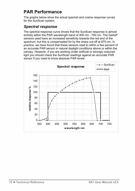
PAR Performance The graphs below show the actual spectral and cosine response curves for the SunScan system.
Spectral response The spectral response curve shows that the SunScan response is almost entirely within the PAR wavelength band of 400 nm - 700 nm. The GaAsP sensors used have an increased sensitivity towards the red end of the spectrum, but this is compensated for by the sharp cut-off at 670 nm. In practice, we have found that these sensors read to within a few percent of an accurate PAR sensor in natural daylight conditions above or within the canopy. However, if you are working under artificial or strongly coloured light you should check the SunScan readings against an accurate PAR sensor if you need to know absolute PAR levels.
Spectral response
0
20
40
60
80
100
120
140
160
350 400 450 500 550 600 650 700 750 wavelength nm
rela
tive
resp
onse
%
SunScan
Ideal
72 Technical Reference SS1 User Manual v2.0

Cosine responses of probe and BF3 The cosine response curves show a diminishing response compared to the ideal at high zenith angles. For this reason, you should avoid taking measurements when the sun is strong and near the horizon. Most studies will be looking at the ratio of incident and transmitted light, and the graph shows the SunScan and Beam Fraction sensor are very closely matched in their cosine and spectral responses, so the small deviations from the ideal will not introduce significant errors.
SunScan system cosine response
00.10.20.30.40.50.60.70.80.9
11.1
0 10 20 30 40 50 60 70 80 90 0 10 20 30 40 50 60 70 80 90
SunScan probe Zenith angle ° Beam Fraction sensor
rela
tive
resp
onse
IdealActualActual / Ideal
SS1 User Manual v2.0 Technical Reference 73

Appendices
A. Logging the probe as a Linear Quantum Sensor This application of the SunScan probe turns it into a simple Line Quantum sensor that can be attached to a data logger. No Data Collection Terminal is used, but you do require a data logger that can supply power to the probe when taking readings. The Delta-T DL2e and GP1 loggers are suitable for this purpose. If you want to mount the probe on a tripod, a camera mount is provided in the base of the probe handle. The probe's coiled RS232 cable is not used, and it must be protected from moisture by enclosing it in a bag with desiccant, for example.
Note: no batteries are required in the probe for this mode, but it does not hurt to leave them in situ.
Wiring connections You must use the (optional) special logging cable which plugs into the socket on the probe handle normally occupied by the Beam Fraction sensor. The cable is 10 metres long. If you need more length, simply join on extra screened multicore cable of a similar type. Make sure the joint is weatherproof. The cores of the probe logging cable have the following functionality:
Core Function Logger Connection orange V+ Power supply positive Sensor power positive
(switched for warm-up) green 0V Power supply negative Sensor power negative (0V) brown HI Signal output positive Input channel + grey LO Signal output negative Input channel - blue not used braid Screen Not connected (see below)
Note: the grey, green and braid are connected internally in the probe handle. Connecting the braid to an earthing point on the logger could create earth loops, and is not recommended.
Output • The output signal is the transmitted PAR irradiance, averaged along
the length of the probe. (Individual photodiode readings are not accessible in the Linear Quantum Sensor mode.)
74 Appendices SS1 User Manual v2.0

• The millivolt output is linear, with a sensitivity of 1 mV = 1 μmol.m-2.s-1. Maximum output is 2.5 V.
Logger requirements • The probe requires a voltage supply of 7-15 V dc (unregulated), at
about 30 mA current. The analogue output is enabled when the external voltage is greater than the battery voltage.
• Configure one channel of the logger for voltage input, with the above sensitivity.
• Use a "warm-up" time of 1 second (the logger must apply the power 1 second before taking its reading).
• The output voltage will be stable 120 ms after applying external power, and is updated every 60 ms while external power remains connected.
B. Logging the Beam Fraction sensor You can log the Beam Fraction sensor in a similar manner, using the (optional) special logging cable for it. Three outputs are available, corresponding to the Total incident PAR, Diffuse PAR and Sun state.
Be aware that separately logged incident PAR readings cannot be merged with probe readings of transmitted PAR to give LAI estimates using the SunScan mathematical model.
See also the BF3 Sunshine Sensor User Manual.
Note we can provide no data logger software to combine and process these readings to estimate Leaf Area Index
Sunscan
Separate data logger:SunScan and BFS connected to datalogger, via cables SSDL & BFDL
BFS BFDL
SSDL
SS1 User Manual v2.0 Appendices 75

Glossary
Beam fraction - the fraction of the Total incident PAR in the Direct beam. Beam Fraction Sensor - The BF3 consists of an array of 7 photodiodes under a specially shaped shadow mask, used for measuring Direct and Diffuse light above the canopy. Beer’s law - a general law describing transmission through an absorbing medium. The intensity falls off exponentially with distance through the medium. Cosine response - the response of a sensor to a ray of light is proportional to the cosine of the angle of incidence of the ray (measured from the perpendicular to the sensor surface). CSV (Comma Separated Variable) a file format intended for importing into spreadsheet or database programs. Fields are separated by commas, text is enclosed in quotes. (SunScan use of this file format was discontinued in 2008, when we upgraded SunData to work on Windows Mobile PDAs. We have replaced this file format with TAB format files, which behaves better across international regions when imported into spreadsheets. Data Collection Terminal - the Psion Workabout handheld computer, previously used for driving the SunScan probe, and presenting and storing the results, now superseded PDAs such as the Recon, running Windows Mobile. Diffuse light - light scattered in the atmosphere. It is treated as coming from all parts of the sky with equal intensity i.e. a Uniform Overcast Sky. Direct beam - light coming directly from the sun, with no scattering. Usually treated as if it comes from a point source. ELADP - see Leaf Angle Distribution Emulator - a setting in the SunData software that generates random results, regardless of whether a SunScan probe is connected. Useful for learning to use the software. GMT - Greenwich Mean Time, also called Universal Time (UT). The standard time used for astronomical measurements and calculations. Hemispherical response - the response of the sensor is equal for all light rays coming from above the plane of the sensor surface, independent of angle. LAD - see Leaf Angle Distribution. LAI - see Leaf Area Index. Leaf absorption - the fraction of intercepted PAR that is actually absorbed by the leaf. The remainder is reflected or scattered. Leaf Angle Distribution - a way of describing the distribution of orientations in space of the canopy elements. We model this using the
76 Glossary SS1 User Manual v2.0

Ellipsoidal Leaf Angle Distribution, which describes the distribution of canopy elements as in the same proportions as the surface of an ellipsoid. Using this model, a wide range of different canopy types can be described by a single parameter, the Ellipsoidal Leaf Angle Distribution Parameter (ELADP), which is the ratio of the horizontal to vertical axes of the ellipsoid. An ELADP much greater than 1 describes a canopy of mostly horizontal leaves, an ELADP near 0 describes a canopy of mainly vertical leaves. Leaf Area Index (LAI) - the surface area of leaf per unit of ground area (assuming leaves are flat, and including only one side of each leaf). Instruments like the SunScan cannot differentiate between leaf and stem, so could more correctly be said to estimate Plant Area Index. Local time - the time used in your particular time zone. It varies from GMT by an amount depending on longitude, political boundaries, and any daylight saving time. Mean Leaf Angle (also Mean Tip Angle, Mean Inclination Angle) is the average angle of all the leaf elements relative to the horizontal, weighted according to area. This can be directly related to ELADP. PAR - Photosynthetically Active Radiation is visible light of wavelength 400 nm - 700 nm. It is measured in units of μmol.m-2.s-1 (micromoles per square metre per second) or formerly μE (micro-Einstein). The normal daylight maximum is a little over 2000 μmol.m-2.s-1 . PAR mapping - the study of distribution and variation of PAR within and below a canopy. PRN a text file format intended for directly printable output. Spread - a measure of the relative variation in light intensity along the SunScan probe. It is calculated as the Standard Deviation divided by the Mean (sometimes called coefficient of variation). SunData software- the software used to drive the SunScan probe and calculate and store the results. SunScan probe - the long light sensitive wand and handle used for light readings within the canopy. TAB - a text file format in which data fields are separated by TAB characters. This file format is easily imported into spreadsheets such as Excel, and can incorporate different conventions for number and date formats. Total PAR - the sum of Direct beam PAR and the Diffuse light PAR. Transmission fraction - the fraction of incident light that passes through a given canopy. It can refer to Direct, Diffuse, or Total incident light. Zenith angle - the angle between the centre of the sun and the point directly overhead.
SS1 User Manual v2.0 Glossary 77

Technical Support
Terms and Conditions of sale Our Conditions of Sale (ref: COND: 1/07) set out Delta-T's legal obligations on these matters. The following paragraphs summarise Delta T's position but reference should always be made to the exact terms of our Conditions of Sale, which will prevail over the following explanation. Delta-T warrants that the goods will be free from defects arising out of the materials used or poor workmanship for a period of twelve months from the date of delivery. Delta-T shall be under no liability in respect of any defect arising from fair wear and tear, and the warranty does not cover damage through misuse or inexpert servicing, or other circumstances beyond their control. If the buyer experiences problems with the goods they shall notify Delta-T (or Delta-T’s local distributor) as soon as they become aware of such problem. Delta-T may rectify the problem by replacing faulty parts free of charge, or by repairing the goods free of charge at Delta-T's premises in the UK during the warranty period. If Delta-T requires that goods under warranty be returned to them from overseas for repair, Delta-T shall not be liable for the cost of carriage or for customs clearance in respect of such goods. However, Delta-T requires that such returns are discussed with them in advance and may at their discretion waive these charges. Delta-T shall not be liable to supply products free of charge or repair any goods where the products or goods in question have been discontinued or have become obsolete, although Delta-T will endeavour to remedy the buyer’s problem. Delta-T shall not be liable to the buyer for any consequential loss, damage or compensation whatsoever (whether caused by the negligence of the Delta-T, their employees or distributors or otherwise) which arise from the supply of the goods and/or services, or their use or resale by the buyer. Delta-T shall not be liable to the buyer by reason of any delay or failure to perform their obligations in relation to the goods and/or services if the delay or failure was due to any cause beyond the Delta-T’s reasonable control.
78 Technical Support SS1 User Manual v2.0

Service and Spares Users in countries that have a Delta-T distributor or technical representative should contact them in the first instance. Spare parts for our own instruments can be supplied and can normally be despatched within a few working days of receiving an order. Spare parts and accessories for products not manufactured by Delta-T may have to be obtained from our supplier, and a certain amount of additional delay is inevitable. No goods or equipment should be returned to Delta-T without first obtaining the return authorisation from Delta-T or our distributor. On receipt of the goods at Delta-T you will be given a reference number. Always refer to this reference number in any subsequent correspondence. The goods will be inspected and you will be informed of the likely cost and delay. We normally expect to complete repairs within one or two weeks of receiving the equipment. However, if the equipment has to be forwarded to our original supplier for specialist repairs or recalibration, additional delays of a few weeks may be expected. For contact details see below.
Technical Support Users in countries that have a Delta-T distributor or technical representative should contact them in the first instance. Technical Support is available on Delta-T products and systems. Your initial enquiry will be acknowledged immediately with a reference number. Make sure to quote the reference number subsequently so that we can easily trace any earlier correspondence. In your enquiry, always quote instrument serial numbers, software version numbers, and the approximate date and source of purchase where these are relevant.
Contact Details Tel: +44 (0) 1638 742922 Fax: +44 (0) 1638 743155 email:
Tech Support Team Delta-T Devices Ltd 130 Low Road, Burwell, Cambridge CB25 0EJ, U.K.
[email protected] email: [email protected] web: www.delta-t.co.uk
SS1 User Manual v2.0 Technical Support 79
Index
Cables ...................................................11 Calibrate................................................30 . Calibration
factory .NET .....................................................21 restore............................................30 .PRN file format....................................26
calibrations............................................46 Campbell's Ellipsoidal LAD .................51 A canopy...................................................32 canopy model ........................................55 Absorption ............................................37 canopy transmission..............................54 Accuracy...................................45, 46, 68 Canopy type ..........................................34 Active Sync...........................................20 Canopy type and LAI............................35 All data .................................................19 Carrying Case .................................10, 71 Autolog ...........................................30, 42 CE Conformity........................................2 Auto-logging...........................................7 Change Data File...................................28 Automatic logging ................................42 COM1 ...................................................28 Average interval....................................30 Comms Test ....................................30, 31 Conditions of sale .................................78
B Configuration ........................................22 Constants...............................................28
Batteries ..........................................62, 65 Contact Details......................................79 Beam fraction.......................................76 Copyright ................................................2 Beam Fraction sensor..............................9 Cosine response ....................................76 Beam Fraction Sensor .....................32, 76 CSV.......................................................76 Beam Fraction Sensor Handling ...........45 Beeps ....................................................43 D Beer’s law .............................................76 Beer's law..............................................51 Data Collection Terminal ....................76 belt ........................................................44 data file .................................................22 Belt .......................................................10 data files................................................25 Belts ......................................................44 display...............................................25 BF3 .......................................................63 Data Files ..............................................24 Specifications....................................68 Data.txt..................................................24 BF3 and BFS Terminology.....................9 Date.......................................................31 BF3 Spares............................................71 Default.cfg............................................23 BF-RL4...........................................63, 69 Description..............................................9 bubble level...........................................43 desiccant................................................65 Button ...................................................43 Desiccant...............................................65 Button Actions ......................................13 Diffuse light - hemispherical response.57
Diffuse light..........................................76 C Diffuse light - cosine response..............57
Diffuse light transmission ...............54, 58 cables ....................................................45 Direct and Diffuse.................................34
80 Index SS1 User Manual v2.0

Direct beam ..........................................76 Leaf Area Index ................................7, 77 Leaf constants .......................................22 Display..................................................29 Levelling ...............................................43 Display mode ........................................22 Light level .............................................36 Load Settings ........................................27 E Local time ............................................77 logger cable...........................................11 ELADP .....................................28, 37, 76 Logger requirements .............................75 Emulator ...................................14, 28, 76 Logging ..........................................42, 74 End of File ............................................27 Longitude & Latitude............................31 Environmental.......................................48
errors .....................................................43 M Exit........................................................27
Experiment Design ...............................32 External Sensor .....................................28 Maintenance..........................................62
mapping ................................................77 Mean Leaf Angle..................................77 F Mean Leaf Angle and ELADP..............39 Measurement modes..............................40 factory calibration.................................47 Measurement procedures ......................43 File Menus....................................................27 transfer ..............................................21 Modelling..............................................59 File menu options..................................27 moisture ................................................48 firmware version ...................................31
Format Tab............................................27 N Fractional Interception ............................7
New File................................................28 G Night time .............................................30 Glossary ................................................76
O GMT .....................................................76 Group name ..........................................29
OverView................................................7
H P
Hemispherical response .......................76 PAR.......................................................77
Cosine response.................................73 I spectral response ...............................72 PAR absorption and scattering..............59 Install SunData......................................21 PAR calibration.....................................66 PAR calibrations ...................................46 L PAR Mapping .........................................7 PAR measurements .................................7 LAD ......................................................76 PAR Readings .......................................41 LAI......................................17, 32, 33, 76 Parts and Accessories..............................8 LAI Readings........................................41 PC Operations .......................................20 LAI theory ............................................49 PDA ........................................................9 Leaf absorption ....................................76 PDA Belt and Holsters ..........................44 Leaf Adsorption ....................................28 Plot name ..............................................29 Leaf Angle Distribution .......................76
SS1 User Manual v2.0 Index 81

PRN ......................................................77 T protection ..............................................48 Protective Case .....................................44 TAB separated .TXT.............................25
Technical Support .................................78 Terms ....................................................78 Q time .......................................................22 Time Quick Start ............................................13
Local time .........................................28 Set time .............................................28 R Time of day...........................................36
Title.......................................................29 Radio Link ............................................10 Total PAR .............................................77 Specifications....................................69 Transmission fraction ..........................77 Read................................................13, 15 Transmitter module ...............................65 Read interval.........................................30 tripod...............................................44, 45 Recalibrate ......................................30, 46 Tripod Recon PDA
Specifications....................................71 Specifications....................................69 Trouble shooting .................................20 Recon PDA batteries.............................64 Troubleshooting ....................................67 references..............................................61
regional settings ....................................25 U Review Data....................................19, 27
uncertainties ..........................................50 S Utilities menu options ...........................30 Utils.......................................................30 Sample name.........................................29
Sampling volume ..................................35 V Save Settings.........................................27
Serial cables ..........................................11 Version and serial number location.......67 Service ..................................................79 version number......................................31 settings ..................................................22
Settings .................................................16 Site ........................................................22 W Sleep .....................................................30 Spares....................................................79 Warning Spares Kit .............................................71 PDA buttons......................................13 Specifications........................................68 Warnings.................................................2 Spread .............................................47, 77 weather conditions ................................36 SS1-RL4 .........................................63, 69 Windows Mobile Device Centre ...........20 Start.......................................................30 Windows XP & Vista ..........................20 Start of File ...........................................27 Store......................................................13 Z Straps ....................................................44 sun’s position ........................................36 zenith angle ...........................................36 SunData................................................77 Zenith angle .........................................77 SunData software....................................9 zenith angles .........................................60 SunScan probe ......................................77
specs..................................................68 System Connection Options..................12
82 Index SS1 User Manual v2.0

SS1 User Manual v2.0 Index 83