Embed Size (px)
Citation preview

CAN-BusFieldbus Interface for S300 / S700
Edition 07/2016
Translation of the original manual
Keep the manual as a product component
during the life span of the product.
Pass the manual to future users / owners
of the product.
File s300700can_e.***

Previous edit ions
Edition Comments
10 / 2005 First edition (starting from firmware 1.32 - CAN version 0.41)
11 / 2005 Reference and examples combined to one manual
09 / 2006 New design, SDO renamed to Object, Index improved
11 / 2006 Updated for S700 family, Termination resistor (interface) corrected, new objects
08 / 2007 Symbols, Standards
01 / 2008 Corrections, new objects, symbols acc. to ANSI Z535
12 / 2008 Minor corrections
07 / 2009 Correction Status Machine Bit 6, Can logo, product brand
12 / 2009 Minor corrections
06 / 2010 SDOs for Safety cards new, minor corrections
12 / 2010 Object 6094, new company name
05 / 2012 Examples corrected, cover page design
07 / 2014 Warning notes updated, Cover page design
10 / 2014 Safetycards S3 and S4 added, homing methods updated
04 / 2016 Warning signs updated, european directives updated, safe voltage changed to 50V
07 / 2016 ASCII command reference updated
Technical changes to improve the performance of the equipment may be made without prior notice !
All rights reserved. No part of this work may be reproduced in any form (by photocopying microfilm or any other method)
or processed, copied or distributed by electronic means, without the written permission of Kollmorgen Europe GmbH.

1 General1.1 About this manual . . . . . . . . . . . . . . . . . . . . . . . . . . . . . . . . . . . . . . . . . . . . . . . . . . . . . . . . . . . . . . . . . . . . . . . 7
1.2 Target group . . . . . . . . . . . . . . . . . . . . . . . . . . . . . . . . . . . . . . . . . . . . . . . . . . . . . . . . . . . . . . . . . . . . . . . . . . . 7
1.3 Hints for the online edition (PDF format) . . . . . . . . . . . . . . . . . . . . . . . . . . . . . . . . . . . . . . . . . . . . . . . . . . . . . . 7
1.4 Use as directed . . . . . . . . . . . . . . . . . . . . . . . . . . . . . . . . . . . . . . . . . . . . . . . . . . . . . . . . . . . . . . . . . . . . . . . . . 8
1.5 Symbols . . . . . . . . . . . . . . . . . . . . . . . . . . . . . . . . . . . . . . . . . . . . . . . . . . . . . . . . . . . . . . . . . . . . . . . . . . . . . . . 8
1.6 Abbreviations . . . . . . . . . . . . . . . . . . . . . . . . . . . . . . . . . . . . . . . . . . . . . . . . . . . . . . . . . . . . . . . . . . . . . . . . . . . 8
1.7 Basic features implemented by CANopen . . . . . . . . . . . . . . . . . . . . . . . . . . . . . . . . . . . . . . . . . . . . . . . . . . . . . 9
1.8 Transmission rate and procedure. . . . . . . . . . . . . . . . . . . . . . . . . . . . . . . . . . . . . . . . . . . . . . . . . . . . . . . . . . . . 9
1.9 Response to BUSOFF communication faults. . . . . . . . . . . . . . . . . . . . . . . . . . . . . . . . . . . . . . . . . . . . . . . . . . . 9
2 Installation / Setup2.1 Important notes . . . . . . . . . . . . . . . . . . . . . . . . . . . . . . . . . . . . . . . . . . . . . . . . . . . . . . . . . . . . . . . . . . . . . . . . 10
2.2 Setting the station address and the transmission rate . . . . . . . . . . . . . . . . . . . . . . . . . . . . . . . . . . . . . . . . . . . 11
2.3 CANopen interface (X6) . . . . . . . . . . . . . . . . . . . . . . . . . . . . . . . . . . . . . . . . . . . . . . . . . . . . . . . . . . . . . . . . . . 12
2.4 CAN-bus cable. . . . . . . . . . . . . . . . . . . . . . . . . . . . . . . . . . . . . . . . . . . . . . . . . . . . . . . . . . . . . . . . . . . . . . . . . 12
2.5 Guide to Setup . . . . . . . . . . . . . . . . . . . . . . . . . . . . . . . . . . . . . . . . . . . . . . . . . . . . . . . . . . . . . . . . . . . . . . . . . 13
2.6 Important configuration parameters for CAN bus operation . . . . . . . . . . . . . . . . . . . . . . . . . . . . . . . . . . . . . . . 13
3 CANopen communication profile3.1 General description of CAN . . . . . . . . . . . . . . . . . . . . . . . . . . . . . . . . . . . . . . . . . . . . . . . . . . . . . . . . . . . . . . . 14
3.2 Construction of the Communication Object Identifier . . . . . . . . . . . . . . . . . . . . . . . . . . . . . . . . . . . . . . . . . . . . 15
3.3 Definition of the used data types . . . . . . . . . . . . . . . . . . . . . . . . . . . . . . . . . . . . . . . . . . . . . . . . . . . . . . . . . . . 15
3.3.1 Basic data types. . . . . . . . . . . . . . . . . . . . . . . . . . . . . . . . . . . . . . . . . . . . . . . . . . . . . . . . . . . . . . . . . . . 16
3.3.1.1 Unsigned Integer. . . . . . . . . . . . . . . . . . . . . . . . . . . . . . . . . . . . . . . . . . . . . . . . . . . . . . . . . . . . . . . 16
3.3.1.2 Signed Integer. . . . . . . . . . . . . . . . . . . . . . . . . . . . . . . . . . . . . . . . . . . . . . . . . . . . . . . . . . . . . . . . . 16
3.3.2 Mixed data types . . . . . . . . . . . . . . . . . . . . . . . . . . . . . . . . . . . . . . . . . . . . . . . . . . . . . . . . . . . . . . . . . . 16
3.3.3 Extended data types . . . . . . . . . . . . . . . . . . . . . . . . . . . . . . . . . . . . . . . . . . . . . . . . . . . . . . . . . . . . . . . 17
3.3.3.1 Octet String . . . . . . . . . . . . . . . . . . . . . . . . . . . . . . . . . . . . . . . . . . . . . . . . . . . . . . . . . . . . . . . . . . . 17
3.3.3.2 Visible String . . . . . . . . . . . . . . . . . . . . . . . . . . . . . . . . . . . . . . . . . . . . . . . . . . . . . . . . . . . . . . . . . . 17
3.4 Communication Objects . . . . . . . . . . . . . . . . . . . . . . . . . . . . . . . . . . . . . . . . . . . . . . . . . . . . . . . . . . . . . . . . . . 17
3.4.1 Network Management Objects (NMT) . . . . . . . . . . . . . . . . . . . . . . . . . . . . . . . . . . . . . . . . . . . . . . . . . . 18
3.4.2 Synchronization Object (SYNC). . . . . . . . . . . . . . . . . . . . . . . . . . . . . . . . . . . . . . . . . . . . . . . . . . . . . . . 18
3.4.3 Time-Stamp Object (TIME) . . . . . . . . . . . . . . . . . . . . . . . . . . . . . . . . . . . . . . . . . . . . . . . . . . . . . . . . . . 18
3.4.4 Emergency Object (EMCY) . . . . . . . . . . . . . . . . . . . . . . . . . . . . . . . . . . . . . . . . . . . . . . . . . . . . . . . . . . 18
3.4.4.1 Application of the Emergency Object . . . . . . . . . . . . . . . . . . . . . . . . . . . . . . . . . . . . . . . . . . . . . . . 19
3.4.4.2 Composition of the Emergency Object . . . . . . . . . . . . . . . . . . . . . . . . . . . . . . . . . . . . . . . . . . . . . . 19
3.4.5 Service Data Objects (SDO) . . . . . . . . . . . . . . . . . . . . . . . . . . . . . . . . . . . . . . . . . . . . . . . . . . . . . . . . . 20
3.4.5.1 Composition of the Service Data Object . . . . . . . . . . . . . . . . . . . . . . . . . . . . . . . . . . . . . . . . . . . . . 20
3.4.5.2 Initiate SDO Download Protocol . . . . . . . . . . . . . . . . . . . . . . . . . . . . . . . . . . . . . . . . . . . . . . . . . . . 21
3.4.5.3 Download SDO Segment Protocol . . . . . . . . . . . . . . . . . . . . . . . . . . . . . . . . . . . . . . . . . . . . . . . . . 21
3.4.5.4 Initiate SDO Upload Protocol . . . . . . . . . . . . . . . . . . . . . . . . . . . . . . . . . . . . . . . . . . . . . . . . . . . . . 21
3.4.5.5 Upload SDO Segment Protocol. . . . . . . . . . . . . . . . . . . . . . . . . . . . . . . . . . . . . . . . . . . . . . . . . . . . 21
3.4.5.6 Abort SDO Protocol. . . . . . . . . . . . . . . . . . . . . . . . . . . . . . . . . . . . . . . . . . . . . . . . . . . . . . . . . . . . . 22
3.4.6 Process Data Object (PDO) . . . . . . . . . . . . . . . . . . . . . . . . . . . . . . . . . . . . . . . . . . . . . . . . . . . . . . . . . . 22
3.4.6.1 Transmission modes . . . . . . . . . . . . . . . . . . . . . . . . . . . . . . . . . . . . . . . . . . . . . . . . . . . . . . . . . . . . 23
3.4.6.2 Trigger modes . . . . . . . . . . . . . . . . . . . . . . . . . . . . . . . . . . . . . . . . . . . . . . . . . . . . . . . . . . . . . . . . . 23
3.4.7 Nodeguard . . . . . . . . . . . . . . . . . . . . . . . . . . . . . . . . . . . . . . . . . . . . . . . . . . . . . . . . . . . . . . . . . . . . . . . 24
3.4.8 Heartbeat . . . . . . . . . . . . . . . . . . . . . . . . . . . . . . . . . . . . . . . . . . . . . . . . . . . . . . . . . . . . . . . . . . . . . . . . 25
4 CANopen Drive Profile4.1 Emergency Messages . . . . . . . . . . . . . . . . . . . . . . . . . . . . . . . . . . . . . . . . . . . . . . . . . . . . . . . . . . . . . . . . . . . 26
4.2 General Definitions. . . . . . . . . . . . . . . . . . . . . . . . . . . . . . . . . . . . . . . . . . . . . . . . . . . . . . . . . . . . . . . . . . . . . . 27
4.2.1 General Objects . . . . . . . . . . . . . . . . . . . . . . . . . . . . . . . . . . . . . . . . . . . . . . . . . . . . . . . . . . . . . . . . . . . 27
4.2.1.1 Object 1000h: Device Type (DS301). . . . . . . . . . . . . . . . . . . . . . . . . . . . . . . . . . . . . . . . . . . . . . . . 27
4.2.1.2 Object 1001h: Error register (DS301) . . . . . . . . . . . . . . . . . . . . . . . . . . . . . . . . . . . . . . . . . . . . . . . 27
4.2.1.3 Object 1002h: Manufacturer Status Register (DS301) . . . . . . . . . . . . . . . . . . . . . . . . . . . . . . . . . . 28
4.2.1.4 Object 1003h: Predefined Error Field (DS301) . . . . . . . . . . . . . . . . . . . . . . . . . . . . . . . . . . . . . . . . 29
4.2.1.5 Object 1005h: COB-ID of the SYNC Message (DS301) . . . . . . . . . . . . . . . . . . . . . . . . . . . . . . . . . 30
4.2.1.6 Object 1006h: Communication Cycle Period (DS301). . . . . . . . . . . . . . . . . . . . . . . . . . . . . . . . . . . 30
4.2.1.7 Object 1008h: Manufacturer Device Name (DS301) . . . . . . . . . . . . . . . . . . . . . . . . . . . . . . . . . . . . 30
CANopen for S300/S700 3
Kollmorgen 07/2016 Contents
Page

4.2.1.8 Object 1009h: Manufacturer Hardware Version . . . . . . . . . . . . . . . . . . . . . . . . . . . . . . . . . . . . . . . 31
4.2.1.9 Object 100Ah: Manufacturer Software Version (DS301). . . . . . . . . . . . . . . . . . . . . . . . . . . . . . . . . 31
4.2.1.10 Object 100Ch: Guard Time (DS301) . . . . . . . . . . . . . . . . . . . . . . . . . . . . . . . . . . . . . . . . . . . . . . . . 31
4.2.1.11 Object 100Dh: Lifetime Factor (DS301) . . . . . . . . . . . . . . . . . . . . . . . . . . . . . . . . . . . . . . . . . . . . . 32
4.2.1.12 Object 1010h: Store Parameters (DS301). . . . . . . . . . . . . . . . . . . . . . . . . . . . . . . . . . . . . . . . . . . . 32
4.2.1.13 Object 1011h: Restore default parameters . . . . . . . . . . . . . . . . . . . . . . . . . . . . . . . . . . . . . . . . . . . 33
4.2.1.14 Object 1014h: COB-ID for Emergency Message (DS301) . . . . . . . . . . . . . . . . . . . . . . . . . . . . . . . 33
4.2.1.15 Object 1016h: Consumer Heartbeat Time. . . . . . . . . . . . . . . . . . . . . . . . . . . . . . . . . . . . . . . . . . . . 34
4.2.1.16 Object 1017h: Producer Heartbeat Time. . . . . . . . . . . . . . . . . . . . . . . . . . . . . . . . . . . . . . . . . . . . . 34
4.2.1.17 Object 1018h: Identity Object (DS301) . . . . . . . . . . . . . . . . . . . . . . . . . . . . . . . . . . . . . . . . . . . . . . 35
4.2.1.18 Object 1026h: OS Prompt . . . . . . . . . . . . . . . . . . . . . . . . . . . . . . . . . . . . . . . . . . . . . . . . . . . . . . . 36
4.2.1.19 Object 2000h: Manufacturer Warnings . . . . . . . . . . . . . . . . . . . . . . . . . . . . . . . . . . . . . . . . . . . . . . 37
4.2.1.20 Object 2014-2017h: 1st-4th Mask 1 to 4 for Transmit-PDO . . . . . . . . . . . . . . . . . . . . . . . . . . . . . . 38
4.2.1.21 Object 2030h: DP-RAM Variables (write only). . . . . . . . . . . . . . . . . . . . . . . . . . . . . . . . . . . . . . . . . 38
4.2.1.22 Object 2040h: Gearing factor for electronic gearing . . . . . . . . . . . . . . . . . . . . . . . . . . . . . . . . . . . . 39
4.2.1.23 Object 2041h: Electric gearing actual value . . . . . . . . . . . . . . . . . . . . . . . . . . . . . . . . . . . . . . . . . . 40
4.2.1.24 Object 2051h: Configuration of Position Registers . . . . . . . . . . . . . . . . . . . . . . . . . . . . . . . . . . . . . 41
4.2.1.25 Object 2052h: Position Registers, absolute. . . . . . . . . . . . . . . . . . . . . . . . . . . . . . . . . . . . . . . . . . . 42
4.2.1.26 Object 2053h: Positions Registers, relative. . . . . . . . . . . . . . . . . . . . . . . . . . . . . . . . . . . . . . . . . . . 42
4.2.1.27 Object 2061h: Current limitation for velocity mode . . . . . . . . . . . . . . . . . . . . . . . . . . . . . . . . . . . . . 43
4.2.1.28 Object 2080h: Motion task for profile position mode . . . . . . . . . . . . . . . . . . . . . . . . . . . . . . . . . . . . 43
4.2.1.29 Object 2081h: Active motion task display . . . . . . . . . . . . . . . . . . . . . . . . . . . . . . . . . . . . . . . . . . . . 43
4.2.1.30 Object 2082h: Copy motion tasks . . . . . . . . . . . . . . . . . . . . . . . . . . . . . . . . . . . . . . . . . . . . . . . . . . 44
4.2.1.31 Object 2083h: Delete Motion tasks . . . . . . . . . . . . . . . . . . . . . . . . . . . . . . . . . . . . . . . . . . . . . . . . . 44
4.2.1.32 Object 2090h: DP-RAM Variables (read only). . . . . . . . . . . . . . . . . . . . . . . . . . . . . . . . . . . . . . . . . 44
4.2.1.33 Object 20A0h: Latch position 1, positive edge. . . . . . . . . . . . . . . . . . . . . . . . . . . . . . . . . . . . . . . . . 45
4.2.1.34 Object 20A1h: Latch position 1, negative edge . . . . . . . . . . . . . . . . . . . . . . . . . . . . . . . . . . . . . . . 45
4.2.1.35 Object 20A2h: Latch position 2, positive edge . . . . . . . . . . . . . . . . . . . . . . . . . . . . . . . . . . . . . . . . 45
4.2.1.36 Object 20A3h: Latch position 2, negative edge . . . . . . . . . . . . . . . . . . . . . . . . . . . . . . . . . . . . . . . 46
4.2.1.37 Object 20A4h: Latch Control Register . . . . . . . . . . . . . . . . . . . . . . . . . . . . . . . . . . . . . . . . . . . . . . 46
4.2.1.38 Object 20B0h: Trigger Variable Digital Input 20 . . . . . . . . . . . . . . . . . . . . . . . . . . . . . . . . . . . . . . . 47
4.2.1.39 Object 20B1h: Control Word Digital Inputs 5...20. . . . . . . . . . . . . . . . . . . . . . . . . . . . . . . . . . . . . . 47
4.2.1.40 Object 20B2h: Analog Inputs. . . . . . . . . . . . . . . . . . . . . . . . . . . . . . . . . . . . . . . . . . . . . . . . . . . . . . 48
4.2.1.41 Object 2100h: Write Dummy . . . . . . . . . . . . . . . . . . . . . . . . . . . . . . . . . . . . . . . . . . . . . . . . . . . . . . 49
4.2.1.42 Object 2101h: Read Dummy. . . . . . . . . . . . . . . . . . . . . . . . . . . . . . . . . . . . . . . . . . . . . . . . . . . . . . 49
4.2.1.43 Object 60FDh: Digital inputs (DS402) . . . . . . . . . . . . . . . . . . . . . . . . . . . . . . . . . . . . . . . . . . . . . . . 49
4.2.1.44 Object 6502h: Supported drive modes (DS402) . . . . . . . . . . . . . . . . . . . . . . . . . . . . . . . . . . . . . . . 50
4.3 PDO Configuration. . . . . . . . . . . . . . . . . . . . . . . . . . . . . . . . . . . . . . . . . . . . . . . . . . . . . . . . . . . . . . . . . . . . . . 50
4.3.1 Receive PDOs (RXPDO) . . . . . . . . . . . . . . . . . . . . . . . . . . . . . . . . . . . . . . . . . . . . . . . . . . . . . . . . . . . . 51
4.3.1.1 Objects 1400-1403h: 1st - 4th RXPDO communication parameter (DS301). . . . . . . . . . . . . . . . . . 51
4.3.1.2 Objects 1600-1603h: 1st - 4th RXPDO mapping parameter (DS301) . . . . . . . . . . . . . . . . . . . . . . . 52
4.3.1.3 Default RXPDO definition . . . . . . . . . . . . . . . . . . . . . . . . . . . . . . . . . . . . . . . . . . . . . . . . . . . . . . . . 52
4.3.2 Transmit PDOs (TXPDO). . . . . . . . . . . . . . . . . . . . . . . . . . . . . . . . . . . . . . . . . . . . . . . . . . . . . . . . . . . . 53
4.3.2.1 Objects 1800-1803h: 1st - 4th TXPDO communication parameter (DS301) . . . . . . . . . . . . . . . . . . 53
4.3.2.2 Objects 1A00-1A03h: 1st - 4th TXPDO mapping parameter (DS301). . . . . . . . . . . . . . . . . . . . . . . 54
4.3.2.3 Default TXPDO definition . . . . . . . . . . . . . . . . . . . . . . . . . . . . . . . . . . . . . . . . . . . . . . . . . . . . . . . . 55
4.4 Device control (dc) . . . . . . . . . . . . . . . . . . . . . . . . . . . . . . . . . . . . . . . . . . . . . . . . . . . . . . . . . . . . . . . . . . . . . . 56
4.4.1 Status Machine (DS402) . . . . . . . . . . . . . . . . . . . . . . . . . . . . . . . . . . . . . . . . . . . . . . . . . . . . . . . . . . . . 56
4.4.1.1 States of the Status Machine . . . . . . . . . . . . . . . . . . . . . . . . . . . . . . . . . . . . . . . . . . . . . . . . . . . . . 56
4.4.1.2 Transitions of the status machine . . . . . . . . . . . . . . . . . . . . . . . . . . . . . . . . . . . . . . . . . . . . . . . . . . 57
4.4.2 Object Description . . . . . . . . . . . . . . . . . . . . . . . . . . . . . . . . . . . . . . . . . . . . . . . . . . . . . . . . . . . . . . . . . 58
4.4.2.1 Object 6040h: Controlword (DS402) . . . . . . . . . . . . . . . . . . . . . . . . . . . . . . . . . . . . . . . . . . . . . . . . 58
4.4.2.2 Object 6041h: Statusword (DS402). . . . . . . . . . . . . . . . . . . . . . . . . . . . . . . . . . . . . . . . . . . . . . . . . 60
4.4.2.3 Object 6060h: Modes of Operation (DS402) . . . . . . . . . . . . . . . . . . . . . . . . . . . . . . . . . . . . . . . . . . 61
4.4.2.4 Object 6061h: Modes of Operation Display (DS402). . . . . . . . . . . . . . . . . . . . . . . . . . . . . . . . . . . . 62
4.5 Factor Groups (fg) (DS402) . . . . . . . . . . . . . . . . . . . . . . . . . . . . . . . . . . . . . . . . . . . . . . . . . . . . . . . . . . . . . . . 62
4.5.1 General Information . . . . . . . . . . . . . . . . . . . . . . . . . . . . . . . . . . . . . . . . . . . . . . . . . . . . . . . . . . . . . . . . 62
4.5.1.1 Factors . . . . . . . . . . . . . . . . . . . . . . . . . . . . . . . . . . . . . . . . . . . . . . . . . . . . . . . . . . . . . . . . . . . . . . 62
4.5.1.2 Relationship between Physical and Internal Units. . . . . . . . . . . . . . . . . . . . . . . . . . . . . . . . . . . . . . 62
4 CANopen for S300/S700
Contents 07/2016 Kollmorgen
Page

4.5.2 Objects for position calculation . . . . . . . . . . . . . . . . . . . . . . . . . . . . . . . . . . . . . . . . . . . . . . . . . . . . . . . 63
4.5.2.1 Object 6089h: position notation index (DS402) . . . . . . . . . . . . . . . . . . . . . . . . . . . . . . . . . . . . . . . . 63
4.5.2.2 Object 608Ah: position dimension index (DS402) . . . . . . . . . . . . . . . . . . . . . . . . . . . . . . . . . . . . . . 63
4.5.2.3 Object 608Fh: Position encoder resolution (DS402) . . . . . . . . . . . . . . . . . . . . . . . . . . . . . . . . . . . . 64
4.5.2.4 Object 6091h: Gear ratio (DS402). . . . . . . . . . . . . . . . . . . . . . . . . . . . . . . . . . . . . . . . . . . . . . . . . . 65
4.5.2.5 Object 6092h: Feed constant (DS402) . . . . . . . . . . . . . . . . . . . . . . . . . . . . . . . . . . . . . . . . . . . . . . 66
4.5.2.6 Object 6093h: Position factor (DS402) . . . . . . . . . . . . . . . . . . . . . . . . . . . . . . . . . . . . . . . . . . . . . . 67
4.5.2.7 Object 6094h: Velocity encoder factor (DS402) . . . . . . . . . . . . . . . . . . . . . . . . . . . . . . . . . . . . . . . 68
4.5.3 Objects for velocity calculations . . . . . . . . . . . . . . . . . . . . . . . . . . . . . . . . . . . . . . . . . . . . . . . . . . . . . . . 69
4.5.3.1 Object 608Bh: velocity notation index (DS402) . . . . . . . . . . . . . . . . . . . . . . . . . . . . . . . . . . . . . . . . 69
4.5.3.2 Object 608Ch: velocity dimension index (DS402) . . . . . . . . . . . . . . . . . . . . . . . . . . . . . . . . . . . . . . 69
4.5.4 Objects for acceleration calculations . . . . . . . . . . . . . . . . . . . . . . . . . . . . . . . . . . . . . . . . . . . . . . . . . . . 70
4.5.4.1 Object 608Dh: acceleration notation index (DS402) . . . . . . . . . . . . . . . . . . . . . . . . . . . . . . . . . . . . 70
4.5.4.2 Object 608Eh: acceleration dimension index (DS402) . . . . . . . . . . . . . . . . . . . . . . . . . . . . . . . . . . 70
4.5.4.3 Object 6097h: Acceleration factor (DS402) . . . . . . . . . . . . . . . . . . . . . . . . . . . . . . . . . . . . . . . . . . 71
4.6 Profile Velocity Mode (pv) (DS402) . . . . . . . . . . . . . . . . . . . . . . . . . . . . . . . . . . . . . . . . . . . . . . . . . . . . . . . . . 72
4.6.1 General Information . . . . . . . . . . . . . . . . . . . . . . . . . . . . . . . . . . . . . . . . . . . . . . . . . . . . . . . . . . . . . . . . 72
4.6.2 Objects that are defined in this section . . . . . . . . . . . . . . . . . . . . . . . . . . . . . . . . . . . . . . . . . . . . . . . . . 72
4.6.3 Objects that are defined in other sections . . . . . . . . . . . . . . . . . . . . . . . . . . . . . . . . . . . . . . . . . . . . . . . 72
4.6.4 Object Description . . . . . . . . . . . . . . . . . . . . . . . . . . . . . . . . . . . . . . . . . . . . . . . . . . . . . . . . . . . . . . . . . 72
4.6.4.1 Object 606Ch: velocity actual value (DS402) . . . . . . . . . . . . . . . . . . . . . . . . . . . . . . . . . . . . . . . . . 72
4.6.4.2 Object 60FFh: target velocity (DS402) . . . . . . . . . . . . . . . . . . . . . . . . . . . . . . . . . . . . . . . . . . . . . . 72
4.7 Profile Torque Mode (tq) (DS402) . . . . . . . . . . . . . . . . . . . . . . . . . . . . . . . . . . . . . . . . . . . . . . . . . . . . . . . . . . 73
4.7.1 General Information . . . . . . . . . . . . . . . . . . . . . . . . . . . . . . . . . . . . . . . . . . . . . . . . . . . . . . . . . . . . . . . . 73
4.7.2 Objects that are defined in this section . . . . . . . . . . . . . . . . . . . . . . . . . . . . . . . . . . . . . . . . . . . . . . . . . 73
4.7.3 Object description . . . . . . . . . . . . . . . . . . . . . . . . . . . . . . . . . . . . . . . . . . . . . . . . . . . . . . . . . . . . . . . . . 73
4.7.3.1 Object 6071h: Target torque (DS402) . . . . . . . . . . . . . . . . . . . . . . . . . . . . . . . . . . . . . . . . . . . . . . . 73
4.7.3.2 Object 6073h: Max current (DS402) . . . . . . . . . . . . . . . . . . . . . . . . . . . . . . . . . . . . . . . . . . . . . . . . 73
4.7.3.3 Object 6077h: Torque actual value (DS402) . . . . . . . . . . . . . . . . . . . . . . . . . . . . . . . . . . . . . . . . . . 73
4.8 Position Control Function (pc) (DS402) . . . . . . . . . . . . . . . . . . . . . . . . . . . . . . . . . . . . . . . . . . . . . . . . . . . . . . 74
4.8.1 General Information . . . . . . . . . . . . . . . . . . . . . . . . . . . . . . . . . . . . . . . . . . . . . . . . . . . . . . . . . . . . . . . . 74
4.8.2 Objects that are defined in this section . . . . . . . . . . . . . . . . . . . . . . . . . . . . . . . . . . . . . . . . . . . . . . . . . 74
4.8.3 Objects that are defined in other sections . . . . . . . . . . . . . . . . . . . . . . . . . . . . . . . . . . . . . . . . . . . . . . . 74
4.8.4 Object Description . . . . . . . . . . . . . . . . . . . . . . . . . . . . . . . . . . . . . . . . . . . . . . . . . . . . . . . . . . . . . . . . . 74
4.8.4.1 Object 6063h: position actual value* (DS402). . . . . . . . . . . . . . . . . . . . . . . . . . . . . . . . . . . . . . . . . 74
4.8.4.2 Object 6064h: position actual value (DS402) . . . . . . . . . . . . . . . . . . . . . . . . . . . . . . . . . . . . . . . . . 75
4.8.4.3 Object 6065h: Following error window. . . . . . . . . . . . . . . . . . . . . . . . . . . . . . . . . . . . . . . . . . . . . . . 75
4.8.4.4 Object 6067h: Position window (DS402) . . . . . . . . . . . . . . . . . . . . . . . . . . . . . . . . . . . . . . . . . . . . . 75
4.8.4.5 Object 6068h: Position window time (DS402) . . . . . . . . . . . . . . . . . . . . . . . . . . . . . . . . . . . . . . . . . 76
4.8.4.6 Object 60F4h: Following error actual value (DS402). . . . . . . . . . . . . . . . . . . . . . . . . . . . . . . . . . . . 76
4.9 Interpolated Position Mode (ip) (DS402) . . . . . . . . . . . . . . . . . . . . . . . . . . . . . . . . . . . . . . . . . . . . . . . . . . . . . 77
4.9.1 General information . . . . . . . . . . . . . . . . . . . . . . . . . . . . . . . . . . . . . . . . . . . . . . . . . . . . . . . . . . . . . . . . 77
4.9.2 Objects defined in this section . . . . . . . . . . . . . . . . . . . . . . . . . . . . . . . . . . . . . . . . . . . . . . . . . . . . . . . . 77
4.9.3 Object description . . . . . . . . . . . . . . . . . . . . . . . . . . . . . . . . . . . . . . . . . . . . . . . . . . . . . . . . . . . . . . . . . 77
4.9.3.1 Object 60C0h: Interpolation sub mode select . . . . . . . . . . . . . . . . . . . . . . . . . . . . . . . . . . . . . . . . . 77
4.9.3.2 Object 60C1h: Interpolation data record . . . . . . . . . . . . . . . . . . . . . . . . . . . . . . . . . . . . . . . . . . . . . 78
4.9.3.3 Object 60C2h: Interpolation time period . . . . . . . . . . . . . . . . . . . . . . . . . . . . . . . . . . . . . . . . . . . . . 79
4.9.3.4 Object 60C3h: Interpolation sync definition . . . . . . . . . . . . . . . . . . . . . . . . . . . . . . . . . . . . . . . . . . . 79
4.9.3.5 Object 60C4h: Interpolation data configuration . . . . . . . . . . . . . . . . . . . . . . . . . . . . . . . . . . . . . . . . 80
4.10 Homing Mode (hm) (DS402) . . . . . . . . . . . . . . . . . . . . . . . . . . . . . . . . . . . . . . . . . . . . . . . . . . . . . . . . . . . . . . 81
4.10.1 General information . . . . . . . . . . . . . . . . . . . . . . . . . . . . . . . . . . . . . . . . . . . . . . . . . . . . . . . . . . . . . . . . 81
4.10.2 Objects that are defined in this section . . . . . . . . . . . . . . . . . . . . . . . . . . . . . . . . . . . . . . . . . . . . . . . . . 81
4.10.3 Objects that are defined in other sections . . . . . . . . . . . . . . . . . . . . . . . . . . . . . . . . . . . . . . . . . . . . . . . 81
4.10.4 Object Description . . . . . . . . . . . . . . . . . . . . . . . . . . . . . . . . . . . . . . . . . . . . . . . . . . . . . . . . . . . . . . . . . 81
4.10.4.1 Object 607Ch: homing offset (DS402). . . . . . . . . . . . . . . . . . . . . . . . . . . . . . . . . . . . . . . . . . . . . . . 81
4.10.4.2 Object 6098h: homing method (DS402) . . . . . . . . . . . . . . . . . . . . . . . . . . . . . . . . . . . . . . . . . . . . . 82
4.10.4.2.1 Description of the homing methods . . . . . . . . . . . . . . . . . . . . . . . . . . . . . . . . . . . . . . . . . . . . 83
4.10.4.3 Object 6099h: homing speeds (DS402) . . . . . . . . . . . . . . . . . . . . . . . . . . . . . . . . . . . . . . . . . . . . . 83
4.10.4.4 Object 609Ah: homing acceleration (DS402) . . . . . . . . . . . . . . . . . . . . . . . . . . . . . . . . . . . . . . . . . 83
4.10.5 Homing Mode Sequence . . . . . . . . . . . . . . . . . . . . . . . . . . . . . . . . . . . . . . . . . . . . . . . . . . . . . . . . . . . . 84
CANopen for S300/S700 5
Kollmorgen 07/2016 Contents
Page
4.11 Profile Position Mode (pp) . . . . . . . . . . . . . . . . . . . . . . . . . . . . . . . . . . . . . . . . . . . . . . . . . . . . . . . . . . . . . . . . 84
4.11.1 General Information . . . . . . . . . . . . . . . . . . . . . . . . . . . . . . . . . . . . . . . . . . . . . . . . . . . . . . . . . . . . . . . . 84
4.11.2 Objects that are defined in this section . . . . . . . . . . . . . . . . . . . . . . . . . . . . . . . . . . . . . . . . . . . . . . . . . 84
4.11.3 Objects that are defined in other sections . . . . . . . . . . . . . . . . . . . . . . . . . . . . . . . . . . . . . . . . . . . . . . . 84
4.11.4 Object description . . . . . . . . . . . . . . . . . . . . . . . . . . . . . . . . . . . . . . . . . . . . . . . . . . . . . . . . . . . . . . . . . 85
4.11.4.1 Object 607Ah: target position (DS402) . . . . . . . . . . . . . . . . . . . . . . . . . . . . . . . . . . . . . . . . . . . . . . 85
4.11.4.2 Object 607Dh: Software position limit (DS402) . . . . . . . . . . . . . . . . . . . . . . . . . . . . . . . . . . . . . . . . 85
4.11.4.3 Object 607Fh: Max profile velocity (DS402) . . . . . . . . . . . . . . . . . . . . . . . . . . . . . . . . . . . . . . . . . . 86
4.11.4.4 Object 6080h: Max motor speed (DS402) . . . . . . . . . . . . . . . . . . . . . . . . . . . . . . . . . . . . . . . . . . . . 86
4.11.4.5 Object 6081h: profile velocity (DS402) . . . . . . . . . . . . . . . . . . . . . . . . . . . . . . . . . . . . . . . . . . . . . . 86
4.11.4.6 Object 6083h: profile acceleration (DS402). . . . . . . . . . . . . . . . . . . . . . . . . . . . . . . . . . . . . . . . . . . 87
4.11.4.7 Object 6084h: profile deceleration (DS402). . . . . . . . . . . . . . . . . . . . . . . . . . . . . . . . . . . . . . . . . . . 87
4.11.4.8 Object 6085h: Quick stop deceleration . . . . . . . . . . . . . . . . . . . . . . . . . . . . . . . . . . . . . . . . . . . . . . 87
4.11.4.9 Object 6086h: motion profile type (DS402) . . . . . . . . . . . . . . . . . . . . . . . . . . . . . . . . . . . . . . . . . . . 88
4.11.4.10 Object 60C5h: Max acceleration . . . . . . . . . . . . . . . . . . . . . . . . . . . . . . . . . . . . . . . . . . . . . . . . . . . 88
4.11.5 Functional Description . . . . . . . . . . . . . . . . . . . . . . . . . . . . . . . . . . . . . . . . . . . . . . . . . . . . . . . . . . . . . . 89
5 Appendix5.1 The Object Channel . . . . . . . . . . . . . . . . . . . . . . . . . . . . . . . . . . . . . . . . . . . . . . . . . . . . . . . . . . . . . . . . . . . . . 91
5.1.1 Objects >3500h Manufacturer specific object channel. . . . . . . . . . . . . . . . . . . . . . . . . . . . . . . . . . . . . . 91
5.1.2 ASCII command reference. . . . . . . . . . . . . . . . . . . . . . . . . . . . . . . . . . . . . . . . . . . . . . . . . . . . . . . . . . . 93
5.1.3 Object Dictionary . . . . . . . . . . . . . . . . . . . . . . . . . . . . . . . . . . . . . . . . . . . . . . . . . . . . . . . . . . . . . . . . . 101
5.2 CANopen SDOs for Safety Expansion Card S1/S2/S1-2/S2-2. . . . . . . . . . . . . . . . . . . . . . . . . . . . . . . . . . . . 107
5.2.1 Object 2400h: Safety card serial number. . . . . . . . . . . . . . . . . . . . . . . . . . . . . . . . . . . . . . . . . . . . . . . 107
5.2.2 Object 2401h: Safety card status . . . . . . . . . . . . . . . . . . . . . . . . . . . . . . . . . . . . . . . . . . . . . . . . . . . . . 107
5.2.3 Object 2402h: Safety card I/O status . . . . . . . . . . . . . . . . . . . . . . . . . . . . . . . . . . . . . . . . . . . . . . . . . . 108
5.2.4 Object 2403h: Safety card error register . . . . . . . . . . . . . . . . . . . . . . . . . . . . . . . . . . . . . . . . . . . . . . . 109
5.2.5 Object 2404h: Safety card error stack error number . . . . . . . . . . . . . . . . . . . . . . . . . . . . . . . . . . . . . . 110
5.2.6 Object 2405h: Safety card error stack error time . . . . . . . . . . . . . . . . . . . . . . . . . . . . . . . . . . . . . . . . . 110
5.2.7 Object 2406h: Safety card error stack error index . . . . . . . . . . . . . . . . . . . . . . . . . . . . . . . . . . . . . . . . 111
5.2.8 Object 2407h: Safety card error stack error info . . . . . . . . . . . . . . . . . . . . . . . . . . . . . . . . . . . . . . . . . 111
5.2.9 Object 2408h: Safety card error stack error parameter 1. . . . . . . . . . . . . . . . . . . . . . . . . . . . . . . . . . . 112
5.2.10 Object 2409h: Safety card error stack error parameter 2. . . . . . . . . . . . . . . . . . . . . . . . . . . . . . . . . . . 112
5.2.11 Object 240Ah: Safety card error stack error parameter 3. . . . . . . . . . . . . . . . . . . . . . . . . . . . . . . . . . . 113
5.2.12 Object 240Bh: Safety card error stack error parameter 4. . . . . . . . . . . . . . . . . . . . . . . . . . . . . . . . . . . 113
5.2.13 Object 240Ch: Actual speed . . . . . . . . . . . . . . . . . . . . . . . . . . . . . . . . . . . . . . . . . . . . . . . . . . . . . . . . 114
5.3 Examples . . . . . . . . . . . . . . . . . . . . . . . . . . . . . . . . . . . . . . . . . . . . . . . . . . . . . . . . . . . . . . . . . . . . . . . . . . . . 115
5.3.1 Basic testing of the connection to the S300/S700 controls . . . . . . . . . . . . . . . . . . . . . . . . . . . . . . . . . 115
5.3.2 Example: Operating the Status Machine . . . . . . . . . . . . . . . . . . . . . . . . . . . . . . . . . . . . . . . . . . . . . . . 116
5.3.3 Example: Jog Mode via SDO . . . . . . . . . . . . . . . . . . . . . . . . . . . . . . . . . . . . . . . . . . . . . . . . . . . . . . . 117
5.3.4 Example: Torque Mode via SDO . . . . . . . . . . . . . . . . . . . . . . . . . . . . . . . . . . . . . . . . . . . . . . . . . . . . 117
5.3.5 Example: Jog Mode via PDO. . . . . . . . . . . . . . . . . . . . . . . . . . . . . . . . . . . . . . . . . . . . . . . . . . . . . . . . 118
5.3.6 Example: Torque Mode via PDO . . . . . . . . . . . . . . . . . . . . . . . . . . . . . . . . . . . . . . . . . . . . . . . . . . . . . 119
5.3.7 Example: Homing via SDO . . . . . . . . . . . . . . . . . . . . . . . . . . . . . . . . . . . . . . . . . . . . . . . . . . . . . . . . . 120
5.3.8 Example: Start Motion Task from the internal memory of S300/S700 via SDO . . . . . . . . . . . . . . . . . . 121
5.3.9 Example: Using the Profile Position Mode . . . . . . . . . . . . . . . . . . . . . . . . . . . . . . . . . . . . . . . . . . . . . . 122
5.3.10 Example: ASCII Communication . . . . . . . . . . . . . . . . . . . . . . . . . . . . . . . . . . . . . . . . . . . . . . . . . . . . . 125
5.3.11 Test for SYNC telegrams . . . . . . . . . . . . . . . . . . . . . . . . . . . . . . . . . . . . . . . . . . . . . . . . . . . . . . . . . . . 126
5.3.12 Application: Electric Gearing . . . . . . . . . . . . . . . . . . . . . . . . . . . . . . . . . . . . . . . . . . . . . . . . . . . . . . . . 127
5.3.13 Application: External Trajectory with Interpolated Position Mode. . . . . . . . . . . . . . . . . . . . . . . . . . . . . 128
5.4 Index . . . . . . . . . . . . . . . . . . . . . . . . . . . . . . . . . . . . . . . . . . . . . . . . . . . . . . . . . . . . . . . . . . . . . . . . . . . . . . . 133
6 CANopen for S300/S700
Contents 07/2016 Kollmorgen
Page

1 General
1.1 About this manual
This manual describes the setup, range of functions and software protocol of the Kollmorgen
S300/S700 servo amplifiers with the CANopen communication profile. It forms part of the complete
documentation for the S300/S700 families of servo amplifiers.
The installation and setup of the servo amplifier, as well as all standard functions, are described in
the corresponding instructions manual.
Other parts of the complete documentation for the digital servo amplifier series:
Title Publisher
Instructions manual S300/S700 Kollmorgen
Online-Help with Object Reference Guide in the Setup-Software Kollmorgen
Additional documentation:
Title Publisher
CAN Application (CAL) for Industrial Applications CiA e.V.
Draft Standards 301 (from Version 4.0), 402 CiA e.V.
CAN Specification Version 2.0 CiA e.V.
ISO 11898 ... Controller Area Network (CAN) for high-speed communication
1.2 Target group
This manual addresses personnel with the following qualifications:
Transport : only by personnel with knowledge of handling electrostatically sensitive
components.
Unpacking: only by electrically qualified personnel.
Installation : only by electrically qualified personnel.
Setup : only by qualified personnel with extensive knowledge of electrical
engineering and drive technology
Programming: Software developers, CAN bus project-planners
The qualified personnel must know and observe the following standards:
IEC 60364, IEC 60664, and regional accident prevention regulations.
Qualified Personnel only!
During operation there are deadly hazards, with the possibility of death,severe injury or material damage.
� The user must ensure that the safety instructions in this manual arefollowed.
� The user must ensure that all personnel responsible for working withthe servo amplifier have read and understood the instructions manual.
Training courses are available on request.
1.3 Hints for the online edition (PDF format)
Bookmarks:
Table of contents and index are active bookmarks.
Table of contents and index in the text:
The lines are active cross references. Click on the desired line and the appropriate page is
accessed.
Page/chapter numbers in the text:
Page/chapter numbers with cross references are active. Click at the page/chapter number to reach
the indicated target.
CANopen for S300/S700 7
Kollmorgen 07/2016 General

1.4 Use as directed
Please observe the chapter "Use as directed” in the instructions manual for the servo amplifier.
The CANopen interface serves only for the connection of the servo amplifier to a master via the
CAN-bus. The servo amplifiers are components that are built into electrical apparatus or machinery,
and can only be setup and operated as integral components of such apparatus or machinery.
We only guarantee the conformity of the servo amplifier with the directives listed in the EU
Declaration of Conformity, if the components that we specify are used, and the installation
regulations are followed.
1.5 Symbols
Symbol Indication
DANGERIndicates a hazardous situation which, if not avoided, will result in death or seri-
ous injury.
WARNINGIndicates a hazardous situation which, if not avoided, could result in death or se-
rious injury.
CAUTIONIndicates a hazardous situation which, if not avoided, could result in minor or
moderate injury.
This is not a safety symbol.
Indicates situations which, if not avoided, could result in property damage.
This is not a safety symbol.
This symbol indicates important notes.
Warning of a danger (general). The type of danger is specified by the warning
text next to it.
Warning of danger from electricity and its effects.
Warning of danger from automatic start.
1.6 Abbreviations
The abbreviations used in this manual are explained in the table below.
Abbrev. Meaning
BTB/RTO Ready to operate (standby)
COB Communication Object
COB-ID Communication Object Identifier
EEPROM Electrically erasable/programmable memory
EMC Electromagnetic compatibility
ISO International Standardization Organization
km 1000 m
LED Light-emitting diode
MB Megabyte
NSTOP Limit switch for CCW (left) rotation
PC Personal Computer
PDO Process Data Object
PSTOP Limit switch for CW (right) rotation
RAM Volatile memory
ROD Incremental position encoder
RXPDO Receive PDO
SDO Service Data Object
TXPDO Transmit PDO
8 CANopen for S300/S700
General 07/2016 Kollmorgen

1.7 Basic features implemented by CANopen
When working with the position controller that is integrated in S300/S700 digital servo amplifiers,
the following functions are available:
Setup and general functions:
— homing, set reference point
— provision of a digital setpoint for speed and torque control
— support of the following modes of the CANopen Profile DS402:
» profile position mode
» homing mode
» profile torque mode
» interpolated position mode
» profile velocity mode
Positioning functions:
— execution of a motion task from the motion block memory of the servo amplifier
— execution of a direct motion task
— absolute trajectory, ip-Mode
Data transfer functions:
— transmit a motion task to the motion block memory of the servo amplifier
A motion task consists of the following elements:
» position setpoint (absolute task) or path setpoint (relative task)
» speed setpoint
» acceleration time, braking time
» type of motion task (absolute/relative)
» number of a following task (with or without pause)
— read a motion task from the motion block memory of the servo amplifier
— read actual values
— read the error register
— read the status register
— read/write control parameters
1.8 Transmission rate and procedure
— bus connection and bus medium: CAN-standard ISO 11898 (CAN high-speed)
— transmission rate: max. 1Mbit/s
possible settings for the servo amplifier:
10, 20, 50, 100, 125, 250, 333, 500 (default), 666, 800, 1000 kbit/s
1.9 Response to BUSOFF communication faults
The communication fault BUSOFF is directly monitored and signaled by Level 2 (CAN controller).
This message may have various causes.
A few examples:
— telegrams are transmitted, although there is no other CAN node connected
— CAN nodes have different transmission rates
— the bus cable is faulty
— faulty cable termination causes reflections on the cable.
A BUSOFF is only signaled by the S300/S700 if another CAN node is connected and at least one
object was successfully transmitted to start off with. The BUSOFF condition is signaled by the error
message F23. If the output stage is enabled for the execution of a motion task at the moment when
this fault occurs, then the drive is braked to a stop, using the emergency stop ramp, and the output
stage is disabled.
CANopen for S300/S700 9
Kollmorgen 07/2016 General

2 Installation / Setup
2.1 Important notes
WARNING
High Voltages up to 900V!Risk of electric shock. Residual charges in the capacitors can still havedangerous levels several minutes after switching off the supply voltage.Power and control connections can still be live, even though the motor isnot rotating.
� Install and wire up the equipment only while it is not electrically con-nected.Make sure that the control cabinet is safely isolated (lock-out, warningsigns etc.).The individual supply voltages will not be switched on untilsetup is carried out.
� Measure the voltage in the intermediate (DC-link) circuit and wait untilit has fallen below 50V.
CAUTION
Automatic Start!Risk of death or serious injury for humans working in the machine. Driveswith servo amplifiers in fieldbus systems are remote-controlled machines.They can start to move at any time without previous warning.
� Implement appropriate protective measures to ensure that any unin-tended start-up of the machines cannot result in dangerous situationsfor personnel or machinery.
� The user is responsible for ensuring that, in the event of a failure ofthe servo amplifier, the drive is set to a state that is functional safe, forinstance with the aid of a safe mechanical brake.
� Software limit-switches are not a substitute for the hardwarelimit-switches in the machine.
Assemble the servo amplifier as described in the instructions manuals for S300/S700. Observe all
safety instructions in the instructions manual that belong to the servo amplifier. Follow all the notes
on mounting position, ambient conditions, wiring, and fusing.
10 CANopen for S300/S700
Installation / Setup 07/2016 Kollmorgen

2.2 Setting the station address and the transmission rate
During setup it makes sense to use the keypad on the servo amplifier's front panel to preset the sta-
tion addresse and the Baud rate for communication (see setup instructions in the instructions
manual).
After changing the station address and/or baud rate you must turn the 24V auxiliary supply for the
servo amplifier off and on again for reset.
The station address (range from 1 to 127) can be set in three different ways:
� by using the keypad on the servo amplifier's front panel (see setup instructions in the instruc-
tions manual)
� in the setup software DriveGUI.exe, on the screen page "CAN / Fieldbus”
� by using the ASCII command sequence (nn = address):
ADDR nn � SAVE � COLDSTART
The transmission rate can be set in three different ways:
� by using the keypad on the servo amplifier's front panel (see setup instructions in the instruc-
tions manual)
� In the setup software DriveGUI.exe, on the screen page "CAN / Fieldbus”
� Using the ASCII command sequence (bb = baud rate in kbit/s):
CBAUD bb � SAVE � COLDSTART.
Coding of the transmission rate in the LED display:
Coding Baud Rate in kbit/s Coding Baud Rate in kbit/s
1 10 33 333
2 20 50 500
5 50 66 666
10 100 80 800
12 125 100 1000
25 250
CANopen for S300/S700 11
Kollmorgen 07/2016 Installation / Setup

2.3 CANopen interface (X6)
The interface for connection to the CAN-bus (default : 500 kBaud). The interface is at the same
electrical potential as the RS232 interface. The analog setpoint inputs can still be used.
We can supply special clamp-sleeve connectors, that can easily be made up for bus operation.
2.4 CAN-bus cable
To meet ISO 11898, a bus cable with a characteristic impedance of 120 � should be used. The
maximum usable cable length for reliable communication decreases with increasing transmission
rate. As a guide, you can use the following values which we have measured, but they are not to be
taken as assured limits:
Cable data: Characteristic impedance 100-120 �
Cable capacitance max. 60 nF/km
Lead loop resistance 159.8 �/km
Cable length, depending on the transmission rate
Transmission rate (kBaud) max. cable length (m)
1000 10
500 70
250 115
Lower cable capacitance (max. 30 nF/km) and lower lead resistance
(loop resistance, 115 �/km) make it possible to achieve greater distances.
(Characteristic impedance 150 ± 5� � terminating resistor 150 ± 5�).
For EMC reasons, the SubD connector housing must fulfill the following requirements:
— metal or metalized housing
— provision for cable shielding connection on the housing, large-area connection
12 CANopen for S300/S700
Installation / Setup 07/2016 Kollmorgen
Master
GND
X6
CANH
CANL
GND
CANH
CANL
GND
CANH
CANL
X6 X6
* according to line impedance about 120�
Shield Shield
CANH
CANL
AGND
AGND
+5V
CAN
5
6
9X6
CAN-Server/Client
CAN
120 *Ù
* according to line impedance
CAN ref. to ISO 11898
S300/S700

2.5 Guide to Setup
Only professional personnel with extensive knowledge of control and drive technology are allowed
to setup the servo amplifier.
Check assembly /
installation
Check that all the safety instructions in the instructions manual for
the servo amplifier and this manual have been observed and imple-
mented. Check the setting for the station address and baud rate.
Connect PC,
start setup software
Use the setup software DriveGUI.exe to set the parameters for the
servo amplifier.
Setup basic functions
Start up the basic functions of the servo amplifier and optimize the
current and speed controllers. This section of the setup is described
in the online help of the setup software.
Save parametersWhen the parameters have been optimized, save them in the servo
amplifier.
Start up communication
The altered parameters will only become effective after a soft-
ware-reset (warm boot). To do this, click the Reset button in the tool
bar of the setup software.
It is required, that the software protocol described in Chapter 4 is
implemented in the master.
Adjust the transmission rate of the S300/S700 to match the master.
Test communication
Check for the bootup-message, when you switch on the drive. Do an
SDO read access on index 0x1000 subindex 0 (DeviceType). See
examples from page 115.
CAUTION: Automatic Start
Risk of death or serious injury for humans working in the machine. The drive performing un-
planned movements during commissioning cannot be ruled out. Make sure that, even if the drive
starts to move unintentionally, no danger can result for personnel or machinery. The measures
you must take in this regard for your task are based on the risk assessment of the application.
Setup position controllerSetup the position controller, as described in the setup software
online help.
2.6 Important configuration parameters for CAN bus operation
The following parameters are important for CAN operation:
1. CBAUD : transmission rate for the CAN bus
2. ADDR : The ADDR command defines the fieldbus address of the amplifier. After making a
change to the address, all the parameters must be saved in the EEPROM, and the amplifier must
be switched off and on again.
3. AENA: This can be used to define the state of the software enable when the amplifier is switched
on. The software enable provides an external control with the facility of enabling or disabling the
output stage through software control. On devices that function with an analog setpoint
(OPMODE=1,3), the software enable is set automatically when the amplifier is switched on, so that
these instruments are immediately ready to operate (provided that the hardware enable is present).
For all other instruments, the software enable is set to the value of AENA at switch-on. The varia-
ble AENA also has a function for the reset of the amplifier after a fault (via digital input 1 or through
the ASCII command CLRFAULT). For errors that can be reset through software, after the error/fault
has been cleared, the software enable is set to the state of AENA. In this way, the response of the
amplifier for a software reset is analogous to the switch-on behavior.
CANopen for S300/S700 13
Kollmorgen 07/2016 Installation / Setup

3 CANopen communication profile
This chapter describes the basic services and communication objects of the CANopen communica-
tion profile DS 301, which are used in the S300/S700.
It is assumed that the basic operating functions of the communication profile are known, and
available as reference documentation.
3.1 General description of CAN
The transmission method that is used here is defined in ISO 11898 (Controller Area Network CAN
for high-speed communication).
The Layer-1/2 protocol (Physical Layer/Data Link Layer) that is implemented in all CAN modules
provides, amongst other things, the requirements for data.
Data transport or data request is made by means of a data telegram (Data Frame) with up to 8
bytes of user data, or by a data request telegram (Remote Frame).
Communication objects (COBs) are labeled by an 11-bit Identifier (ID) that also determines the pri-
ority of objects.
A Layer-7 protocol (Application Layer) was developed, to decouple the application from the commu-
nication. The service elements that are provided by the Application Layer make it possible to imple-
ment an application that is spread across the network. These service elements are described in the
CAN Application Layer (CAL) for Industrial Applications.
The communication profile CANopen and the drive profile are mounted on the CAL.
The basic structure of a communication object is shown in the following diagram:
S
O
M
COB-ID
R
T
R
CTRL Data Segment CRC
A
C
K
EOM
SOM Start of message
COB-ID Communication Object Identifier (11-bit)
RTR Remote Transmission Request
CTRL Control Field (e.g. Data Length Code)
Data Segment 0 ... 8 byte (Data-COB)
0 byte (Remote-COB)
CRC Cyclic Redundancy Check
ACK Acknowledge slot
EOM End of message
14 CANopen for S300/S700
CANopen communication profile 07/2016 Kollmorgen

3.2 Construction of the Communication Object Identifier
The following diagram shows the layout of the COB Identifier (COB-ID). The Function Code defines
the interpretation and priority of the particular object.
10 9 8 7 6 5 4 3 2 1 0
Function-Code Module-ID
Bit 0 .. 6 Module ID (servo amplifier's CAN-bus address, range 1 ... 127; is set up in the
setup software or the servo amplifier, � p.11)
Bit 7... 10 Function Code (number of the communication object that is defined in the server)
If an invalid station number (=0 or >127) is set, then the module will be set internally to 1.
The following tables show the default values for the COB Identifier after switching on the servo
amplifier. The objects, which are provided with an index (Communication Parameters at Index), can
have a new ID assigned after the initialization phase. The indices in brackets are optional.
Predefined broadcast objects (send to all nodes):
ObjectFunction code
(binary)
Resulting COB-IDs Communication parameters
at indexDec. Hex.
NMT 0000 0 0h —
SYNC 0001 128 80h (1005h)
TIME 0010 256 100h not supported
Predefined Peer-to-Peer objects (node sends to node):
ObjectFunction code
(binary)
Resulting COB-IDs Communication
parameters
at index
PiorityDec. Hex.
EMERGENCY 0001 129..255 81h..FFh — high
TPDO 1 0011 385..511 181h..1FFh 1800h
RPDO 1 0100 513..639 201h..27Fh 1400h
TPDO 2 0101 641..767 281h..2FFh 1801h
RPDO 2 0110 769..895 301h..37Fh 1401h
TPDO 3 0110 897..1023 381h..3FFh 1802h
RPDO 3 1000 1025..1151 401h..47Fh 1402h
TPDO 4 1001 1153..1279 481h..4FFh 1803h
RPDO 4 1010 1281..1407 501h..57Fh 1403h
SDO (tx*) 1011 1409..1535 581h..5FFh
SDO (rx*) 1100 1537..1663 601h..67Fh
Nodeguard 1110 1793..1919 701h..77Fh (100Eh) low
* tx = direction of transmission: S300/S700 � Master
rx = direction of transmission: Master � S300/S700
3.3 Definition of the used data types
This chapter defines the data types that are used. Each data type can be described by bit-
sequences. These bit-sequences are grouped into "Octets” (bytes). The so-called "Little – Endian”
format (also known as "Intel format") is used for numerical data types (see also: DS301 Application
Layer "General Description of Data Types and Encoding Rules”).
CANopen for S300/S700 15
Kollmorgen 07/2016 CANopen communication profile

3.3.1 Basic data types
3.3.1.1 Unsigned Integer
Data in the basic data type UNSIGNEDn define exclusively positive integers.
The value range is from 0 ... 2n-1. The bit sequence b = b0 ... bn-1 defines the value
UNSIGNEDn(b) = bn-1 2n-1
+ ... + b1 21
+ b0 20
Example: the value 266 = 10Ah is transmitted in the data type UNSIGNED16, in the form of two
octets (1st
octet = 0Ah, 2nd
octet = 01h).
Transmission syntax for the data type UNSIGNEDn
Octet number 1. 2. 3. 4. 5. 6. 7. 8.
UNSIGNED8 b7..b0
UNSIGNED16 b7..b0 b15..b8
UNSIGNED24 b7..b0 b15..b8 b23..b16
UNSIGNED32 b7..b0 b15..b8 b23..b16 b31..b24
UNSIGNED40 b7..b0 b15..b8 b23..b16 b31..b24 b39..b32
UNSIGNED48 b7..b0 b15..b8 b23..b16 b31..b24 b39..b32 b47..b40
UNSIGNED56 b7..b0 b15..b8 b23..b16 b31..b24 b39..b32 b47..b40 b55..b48
UNSIGNED64 b7..b0 b15..b8 b23..b16 b31..b24 b39..b32 b47..b40 b55..b48 b63..b56
3.3.1.2 Signed Integer
Data in the basic data type INTEGERn define both positive and negative integers.
The value range is from -2n-1
-1 ... 2n-1
-1. The bit sequence b = b0..bn-1 defines the value
INTEGERn(b) = bn-2 2n-2
+ ... + b1 21
+ b0 20
with bn-1 = 0
Negative numbers are represented as 2’s complement, which means:
INTEGERn(b) = - INTEGERn(b) - 1 with bn-1 = 1
Example: the value -266 = FEF6h is transmitted in the data type INTEGER16, in the form of two
octets (1st
octet = F6h, 2nd
octet = FEh).
Transmission syntax for the data type INTEGERn
Octet number 1. 2. 3. 4. 5. 6. 7. 8.
INTEGER8 b7..b0
INTEGER16 b7..b0 b15..b8
INTEGER24 b7..b0 b15..b8 b23..b16
INTEGER32 b7..b0 b15..b8 b23..b16 b31..b24
INTEGER40 b7..b0 b15..b8 b23..b16 b31..b24 b39..b32
INTEGER48 b7..b0 b15..b8 b23..b16 b31..b24 b39..b32 b47..b40
INTEGER56 b7..b0 b15..b8 b23..b16 b31..b24 b39..b32 b47..b40 b55..b48
INTEGER64 b7..b0 b15..b8 b23..b16 b31..b24 b39..b32 b47..b40 b55..b48 b63..b56
3.3.2 Mixed data types
Mixed data types combine basic data types (INTEGERn, UNSIGNEDn, REAL). Two types of mixed
data are distinguished:
� STRUCT
This data type is composed of elements with different data types.
� ARRAY
This data type is composed of elements of the same data type.
16 CANopen for S300/S700
CANopen communication profile 07/2016 Kollmorgen

3.3.3 Extended data types
Extended data types are derived from basic data types and mixed data types. The types of
extended data that are supported are defined below.
3.3.3.1 Octet String
The data type OCTET_STRING is defined with the data type ARRAY. Length is the length of the
octet string.
ARRAY[length] OF UNSIGNED8 OCTET_STRINGlength
3.3.3.2 Visible String
The data type VISIBLE_STRING can be defined with the data type UNSIGNED8 or the data type
ARRAY. Permissible values are 00h and the range from 20h to 7Eh. The data are interpreted as 7
bit ASCII code (as per ISO 646-1973(E)). Length is the length of the visible string.
UNSIGNED8 VISIBLE_CHAR
ARRAY[length] OF VISIBLE_CHAR VISIBLE_STRINGlength
3.4 Communication Objects
Communication objects are described with the help of service elements and protocols. Two basic
types of service elements are distinguished:
� Unconfirmed services PDO
� Confirmed services SDO
All services require faultless operation of the Data Link and Physical Layer.
S300/S700 supports communication objects that are described in detail in the following sections:
� Network Management Objects (NMT)
� Synchronization Object (SYNC)
� Emergency Object (EMCY)
� Process Data Object (PDO)
� Service Data Object (SDO)
� Nodeguard
CANopen for S300/S700 17
Kollmorgen 07/2016 CANopen communication profile

3.4.1 Network Management Objects (NMT)
The NMT telegram looks like this:
The drive supports the following network management functions:
cs = 129, reset node: causes a cold-start of the drive.
This deletes all parameters saved in the RAM and loads the
values stored in the EEPROM.
cs = 130, reset communication node:
causes a stop of PDO-communication, gives a new bootup-message
cs = 1, start remote node: starts the CAN node.
I.e. the PDOs of the drive are enabled for operation.
From this moment, transmit-PDOs will be transmitted under event-
control, and cyclical process data operation can commence.
cs = 2, stop remote node: stops the CAN node, I.e. the drive no longer responds to any
received PDOs or transmits any PDOs.
3.4.2 Synchronization Object (SYNC)
The SYNC object usually is used as a periodic Broadcast Object and provides the basic clock for
the bus. SYNC has a high priority, to ensure constant time intervals. The usage of this protocol is
explained in the appendix from page 115. You can use the SYNC object to start motion task of
several axes simultaneously for example.
3.4.3 Time-Stamp Object (TIME)
This communication object is not supported by S300/S700.
3.4.4 Emergency Object (EMCY)
EMCY is event-triggered and generated by an internal fault/error situation. This object is transmitted
afresh for every error. Since the error codes are device-dependent, they are described in the Chap-
ter CANopen Drive Profile (� p. 26). The last 8 Emergency error codes can be read via object
1003.
18 CANopen for S300/S700
CANopen communication profile 07/2016 Kollmorgen
COB-ID = 0
csNODE
ID
10
10 2
NMT MasterStart Remote Node
request
cs = command specifiernode-ID = station address
indication
indication
indication
NMT Slave(s)

3.4.4.1 Application of the Emergency Object
The reaction in the event of an error or fault depends on the error class and is therefore variable.
For this reason, the reaction is described with the aid of an error status machine. The error condi-
tions error- free and error occurred are distinguished. The following transitions are defined:
0. After initialization, the error-free status is taken up if no errors are detected.
No error signal is generated in this condition.
1. The S300/S700 detects an internal error and indicates this in the first three bytes
of the emergency telegram (error code in Bytes 0,1 and error register in Byte 2).
Since the S300/S700 can distinguish between different types of error, Byte 3 of the
manufacturer-specific error field is used to indicate the error category.
2. One error has been reset, but not all. The EMCY telegram contains error code 0000h
and the error register indicates the remaining errors that are present.
The manufacture-specific area is set to zero.
3. A new error has occurred. The S300/S700 remains in the error status and transmits
an EMCY Object with the corresponding error code. The new error code is entered in
Bytes 0 and 1.
4. All errors have been reset. The EMCY telegram contains the error code 0000h,
the error register does not indicate any other errors.
The manufacture-specific area is set to zero.
3.4.4.2 Composition of the Emergency Object
The Emergency Object is composed of 8 bytes, divided as follows:
Byte 0 1 2 3 4 5 6 7
Content Emergency error code
(� p.26)
Error register
(object 1001h)
Category Reserved
If an Emergency Object is generated, the error condition is then signaled to the status machine
(error free / error occurred) by the generation of a second Emergency Object. Only the first four
bytes are relevant in this case (Emergency Error code , Error register, Category). Byte 0/1 contains
the Error Reset code (0000h) and Byte 2 indicates if a possible further error is present. If the error
register contains 00h, the error status is error-free.
Byte 3 contains the category. The interpretations of the error numbers (error code) and the error
categories are described in the section Emergency Messages (� p.26). The error register is
defined through object 1001h Error register.
CANopen for S300/S700 19
Kollmorgen 07/2016 CANopen communication profile
error free
error occurred
0
2
1 4
3

3.4.5 Service Data Objects (SDO)
SDOs are used to implement access to the Object Dictionary. The SDOs are required for
parametrerization and for status polling. Access to an individual object is made with a multiplexer
via the Index and Subindex of the Object Dictionary. The following communication protocols are
supported by S300/S700:
� Initiate SDO Download Protocol
� Download SDO Segment Protocol
� Initiate SDO Upload Protocol
� Upload SDO Segment Protocol
� Abort SDO Transfer Protocol
The definitions of the individual communication services and protocols can be found in DS301.
Examples of the usage of SDOs can be found in the appendix from page 115.
Since an SDO is a confirmed service, the system must always wait for the SDO response telegram
before it is allowed to transmit a new telegram.
3.4.5.1 Composition of the Service Data Object
An SDO consists of the following components:
Byte 1 2 3 4 5 6 7 8
Content rw Index Subindex Data
1. The control byte (Byte 1):
The control byte determines whether the SDO should write or read the content of the entry
in the Object Dictionary. A description of the complete Object Dictionary for
S300/S700 can be found from p. 101.
Data exchange with the S300/S700 is governed by the CMS
multiplexed domain protocols standard, as described in the CAN standard DS 202.
To read data, the control byte must be written in the manner shown below:
Bit 7 6 5 4 3 2 1 0
Content ccs*=2 X X X X X
* ccs � client command specifier (ccs = 2 � initiate upload request)
X � free data
So a value of 0100 0000 (binary) or 40h has to be transmitted in the control byte.
The servo amplifier sends back a corresponding response byte:
Bit 7 6 5 4 3 2 1 0
Content scs*=2 X n e s
* scs � server command specifier (scs = 2 � initiate upload response)
n � only valid for e = s = 1
if this is so, n contains the number of bytes that do not contain data
X � free data
If reading is successfull, the response byte always has set the bits 0 and 1 (e = s = 1).
Encoded byte length in the SDO response:
0x43 - 4 bytes
0x47 - 3 bytes
0x4B - 2 bytes
0x4F - 1 byte.
If an error occurs, scs is set to 4, the response byte is 0x80 and the error information is in
the four byte data field. The decoding of the error can be found on p. 22.
20 CANopen for S300/S700
CANopen communication profile 07/2016 Kollmorgen
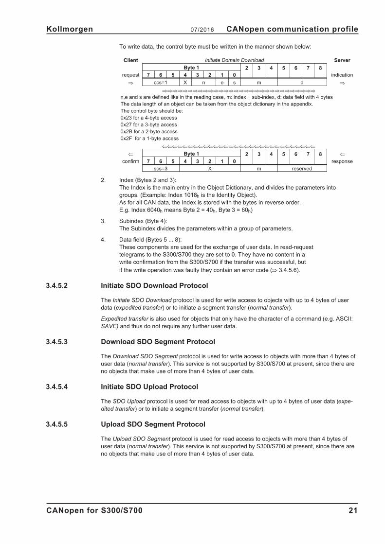
To write data, the control byte must be written in the manner shown below:
Client Initiate Domain Download Server
Byte 1 2 3 4 5 6 7 8
request 7 6 5 4 3 2 1 0 indication
� ccs=1 X n e s m d �
������������������������������
n,e and s are defined like in the reading case, m: index + sub-index, d: data field with 4 bytes
The data length of an object can be taken from the object dictionary in the appendix.
The control byte should be:
0x23 for a 4-byte access
0x27 for a 3-byte access
0x2B for a 2-byte access
0x2F for a 1-byte access
������������������������������
� Byte 1 2 3 4 5 6 7 8 �
confirm 7 6 5 4 3 2 1 0 response
scs=3 X m reserved
2. Index (Bytes 2 and 3):
The Index is the main entry in the Object Dictionary, and divides the parameters into
groups. (Example: Index 1018h is the Identity Object).
As for all CAN data, the Index is stored with the bytes in reverse order.
E.g. Index 6040h means Byte 2 = 40h, Byte 3 = 60h)
3. Subindex (Byte 4):
The Subindex divides the parameters within a group of parameters.
4. Data field (Bytes 5 ... 8):
These components are used for the exchange of user data. In read-request
telegrams to the S300/S700 they are set to 0. They have no content in a
write confirmation from the S300/S700 if the transfer was successful, but
if the write operation was faulty they contain an error code (� 3.4.5.6).
3.4.5.2 Initiate SDO Download Protocol
The Initiate SDO Download protocol is used for write access to objects with up to 4 bytes of user
data (expedited transfer) or to initiate a segment transfer (normal transfer).
Expedited transfer is also used for objects that only have the character of a command (e.g. ASCII:
SAVE) and thus do not require any further user data.
3.4.5.3 Download SDO Segment Protocol
The Download SDO Segment protocol is used for write access to objects with more than 4 bytes of
user data (normal transfer). This service is not supported by S300/S700 at present, since there are
no objects that make use of more than 4 bytes of user data.
3.4.5.4 Initiate SDO Upload Protocol
The SDO Upload protocol is used for read access to objects with up to 4 bytes of user data (expe-
dited transfer) or to initiate a segment transfer (normal transfer).
3.4.5.5 Upload SDO Segment Protocol
The Upload SDO Segment protocol is used for read access to objects with more than 4 bytes of
user data (normal transfer). This service is not supported by S300/S700 at present, since there are
no objects that make use of more than 4 bytes of user data.
CANopen for S300/S700 21
Kollmorgen 07/2016 CANopen communication profile

3.4.5.6 Abort SDO Protocol
The Abort SDO protocol breaks off SDO transmission, and indicates the error that caused the break
in transmission through an abort code (error code). The error code is in the format of an
UNSIGNED32 value. The following table shows possible reasons for an abort SDO.
Abort Code Description
0601 0000h Unsupported access to this object
0601 0001h Attempted read access to a write-only object
0601 0002h Attempted write access to a read-only object
0602 0000h Object does not exist in Object Dictionary
0604 0041h Object cannot be mapped to a PDO
0604 0042h Size and number of mapped objects exceed permissible PDO length
0604 0043h General parameter incompatibility
0607 0010h Data type incompatible, length of service parameter is incompatible
0609 0011h Subindex does not exist
0609 0030h Outside value range for the parameter (only for write access)
0609 0031h Parameter value too high
0609 0032h Parameter value too low
0800 0020h Data cannot be transmitted or saved
0800 0022h Data cannot be transmitted or saved because of device status
FF03 0000h OS cmd buffer full
Abort Codes not listed above are reserved.
3.4.6 Process Data Object (PDO)
PDOs are used for real-time data communication. PDOs can, for instance, be used to set up con-
trollers similar to analog drives. Instead of +/-10VDC setpoints and ROD feedback, digital speed
setpoints and position feedback are attained via PDOs in this case.
Transmission is carried out unconfirmed without a protocol "overhead”. This communication object
uses the unconfirmed communication service.
PDOs are defined via the Object Dictionary for the S300/S700. Mapping is made during the configu-
ration phase, with the help of SDOs. Length is defined with the mapped objects.
The definition of the PDO service and protocol can be found in DS301. Examples of the usage of
PDOs can be found in the appendix from page 115.
Basically, two types of PDOs can be distinguished, depending on the direction of transmission:
� Transmit-PDOs (TPDOs) (S300/S700 � Master)
The TPDOs transmit data from S300/S700 to control system
(e.g actual value objects, instrument status).
� Receive-PDOs (RPDOs) (Master � S300/S700)
The RPDOs receive data from control system to S300/S700
(e.g setpoints).
S300/S700 supports four independent PDO channels for each direction of transmission. The chan-
nels are labeled by the channel numbers 1 to 4.
There are two parameter sets each for the configuration of each of the four possible PDOs, and
they can be set up through the corresponding SDOs:
1. Mapping parameters, to determine which data are available (mapped) in the selected
PDO and to define, which data are contained (see pages 52 and 54 ).
2. Communication parameters, that define whether the PDOs operate in synchronized mode,
or event-driven (objects 1400h to 1403h, 1800h to 1803h).
22 CANopen for S300/S700
CANopen communication profile 07/2016 Kollmorgen

3.4.6.1 Transmission modes
The following PDO transmission modes are distinguished:
� Synchronous transmission
� Asynchronous transmission
The pre-defined SYNC Object is transmitted periodically (bus clock), to synchronize the drives. Syn-
chronous PDOs are transmitted within a pre-defined time window immediately following the SYNC
Object.
The transmission modes are set up with the aid of the PDO communication parameters.
3.4.6.2 Trigger modes
Three different trigger modes are distinguished:
� Event driven
The transmission of the telegrams is triggered by an object-specific event.
� Time driven
If event driven signals put a high strain on the bus, you can determine the period of time after
which a PDO can be transmitted again via the inhibit time (Communication parameter, sub-in-
dex 03h)
� Event Timer driven
If a PDO shall be sent within a defined time interval, even if it doesn’t change, this interval can
be defined by a special SDO.
CANopen for S300/S700 23
Kollmorgen 07/2016 CANopen communication profile
SYNC SYNCSYNC
Synchronous
Asynchronous
time
Synchronous
PDOs LengthPDOs
Object
Window
Object Object

3.4.7 Nodeguard
The Node Guarding protocol is a functional monitoring for the drive. It requires that the drive is
accessed at regular intervals by the CANopen master.
The maximum time interval that is permitted between two Nodeguard telegrams is given by the pro-
duct of the Guard Time (Object 100Ch, � p.31) and the Life Time Factor (Object 100Dh, � p.32). If
one of these two values is 0, then the response monitoring is de-activated.
If the drive is not accessed within the time defined by objects 100Ch and 100Dh, then Warning N04
(response monitoring) appears on the drive, the drive is braked to a stop with the Quickstop ramp,
and any other movement is prevented. (parameter DECSTOP, object 6085 sub0).
The time sequence for node guarding is as shown below:
t = toggle Bit, changes its status with every slave telegram
s = status of the NMT slave status machine
Node guarding is carried out by the Master through RTR telegrams with the COB-ID 700h + slave
node address.
24 CANopen for S300/S700
CANopen communication profile 07/2016 Kollmorgen
NMT Master
COB-ID = ...
remote transmit request
remote transmit request
request
request
indication
indication
response
response
NMT Slave
confirm
Gu
ard
Tim
e
confirm
6..0s
6..0s
7t
7t
0
0
1
1
S300/S700

3.4.8 Heartbeat
The Heartbeat Protocol defines an Error Control Service without need for remote frames. A Heart-
beat Producer transmits a Heartbeat message cyclically. One or more Heartbeat Consumer receive
the indication. The relationship between producer and consumer is configurable via Object 1016h /
1017h. The Heartbeat Consumer guards the reception of the Heartbeat within the Heartbeat Consu-
mer Time. If the Heartbeat is not received within the Heartbeat Consumer Time a Heartbeat Event
will be generated.
Heartbeat protocol:
CANopen for S300/S700 25
Kollmorgen 07/2016 CANopen communication profile
0
0 1
1
6 ... 0s
7r
6 ... 0s
7r
HeartbeatProducer
request
HeartbeatProducerTime
HeartbeatConsumer
indication
Heartbeat
TimeConsumer
Heartbeat Event
request
indication
indication
indication
indication
indication
Heartbeat
TimeConsumer
Write HeartbeatCOB-ID = 1792+Node-ID
r: reserved (always 0)s: state of the Heartbeat Producer
0: BOOTUP4: STOPPED5: OPERATIONAL127: PRE-OPERATIONAL

4 CANopen Drive Profile
4.1 Emergency Messages
Emergency messages are triggered by internal equipment errors. They have a high ID-priority, to
ensure quick access to the bus. An Emergency message contains an error field with pre-defined
error/fault numbers (2 bytes), an error register (1byte), the error category (1 byte) and additional
information (� chapter 3). The higher-value byte of the error number describes the error category,
and the lower-value byte provides the error number in this category.
Error numbers from 0000h to 7FFFh are defined in the communication or drive profile. Error num-
bers from FF00h to FFFFh have manufacturer-specific definitions. The error category can be used
to classify the significance of any errors that occur. The following error categories are defined:
1: Errors that can only be cleared by a reset (COLDSTART command, or Bit 7 in the
control word � p.58). If you reset the amplifier in case of a cat.1 error, the servo amplifier
will be restarted by a coldstart.
2: Errors that can be cleared by Bit 7 in the control word (� p.58).
3: Error messages that may appear when a PDO is processed.
4: Faults, that cannot be cleared by the user.
5: Operating errors/warnings.
The cat. 1 and 2 errors are indicated by blinking of the LED display in the front panel. (Fxx, xx =
error number). The following table describes the various Error Codes:
Error Code Category Description
0000h — Error reset or no error (mandatory)
1000h — Generic error (mandatory)
1080h 5 No BTB/RTO (status not ready for operation)
2330h 2 Error in ground connection (F22)
2380h 1 Error in motor connection (phase fault) (F12)
3100h 2 No mains/line-BTB (F16)
3110h 2 Overvoltage in DC-bus/DC-link (F02)
3120h 2 Undervoltage in DC-bus/DC-link (F05)
3130h 2 Supply line phase missing (with PMODE = 2) (F19)
4110h 2 Ambient temperature too high (F13)
4210h 1 Heat sink temperature too high (F01)
4310h 1 Motor temperature too high (F06)
5111h 1 Fault in �15V auxiliary voltage (F07)
5380h 1 Fault in A/D converter (F17)
5400h 1 Fault in output stage (F14)
5420h 1 Ballast (chopper) (F18)
5441h 1 Operating error for AS-option (F27)
5530h 1 Serial EEPROM (F09)
6320h 3 Parameter error
7111h 1 Braking error/fault (F11)
7122h 1 Commutation error (F25)
7181h 5 Could not enable S300/S700
7303h 1 Feedback device error (F04)
7305h 1 Signal failure digital encoder input (F10)
8182h 1 CAN bus off (F23)
8331h 2 I2t (torque fault, F15)
8480h 2 Overspeed (F08)
8611h 2 Lag/following error (n03/F03)
8681h 5 Invalid motion task number
FF01h 1 Serious exception error (F32)
FF02h 3 Error in PDO elements
FF04h 1 Slot error (F20)
FF05h 1 Handling error (F21)
FF06h 2 Warning display as error (F24)
FF07h 2 Homing error (drove onto HW limit switch) (F26)
FF08h 2 Sercos error (F29)
FF11h 2 Emergency timeout failure(F30)
26 CANopen for S300/S700
CANopen Drive Profile 07/2016 Kollmorgen

4.2 General Definitions
This chapter describes objects with a general validity (e.g. Object 1000h Device Type). The next
section explains the free configuration of Process Data Objects ("free mapping”).
4.2.1 General Objects
4.2.1.1 Object 1000h: Device Type (DS301)
This object describes the device type (servo drive) and device functionality (DS402 drive profile).
Definition:
MSB LSB
Additional information Device profile number
Mode bits Type 402d=192h
31 24 23 16 15 0
The device profile number is DS402, the type is 2 for servo amplifiers, the mode bits 28 to 31 are
manufacturer specific and may be changed from its actual value of 0. A read access delivers
0x00002192 at the moment.
Index 1000h
Name device type
Object code VAR
Data type UNSIGNED32
Category mandatory
Access ro
PDO mapping not possible
Value range UNSIGNED32
Default value no
4.2.1.2 Object 1001h: Error register (DS301)
This object is an error register for the device. The device can map internal errors into this byte. It is
a part of an Emergency object.
Index 1001h
Name Error register
Object code VAR
Data type UNSIGNED8
Category mandatory
Access ro
PDO mapping not possible
Value range UNSIGNED8
Default value no
Error reasons to be signaled:If a bit is set to 1 the specified error has occurred. The generic error is
signaled at any error situation.
Bit Description Bit Description
0 generic error 4 communication error (overrun, error state)
1 current 5 device profile specific
2 voltage 6 reserved (always 0)
3 temperature 7 manufacturer specific
CANopen for S300/S700 27
Kollmorgen 07/2016 CANopen Drive Profile

4.2.1.3 Object 1002h: Manufacturer Status Register (DS301)
The manufacturer status register contains important drive informations.
Index 1002h
Name Manufacturer Status Register
Object code VAR
Data type UNSIGNED32
Category optional
Access ro
PDO mapping possible
Value range UNSIGNED32
Default value no
The following table shows the bit assignment for the status register:
Bit Description
0 1 = Movement (positioning, homing) active
1 1 = reference point set
2 1 = reference switch high (home-position)
3 1 = In Position
4 1 = Position latch at input 2 (positive transition)
5 reserved
6 reserved
7 reserved
8 reserved
9 reserved
10 1 = Initialization phase finished
11 reserved
12 1 = Motor stand still message (threshold VEL0)
13 1 = Safety relay selected (AS-option)
14 1 = Power stage enabled
15 1 = Error state
16 1 = Homing move active
17 1 = Jog move active
18 1 = position latch at input 2 (negative transition)
19 1 = Emergency stop active
20 1 = Position latch at input 1 (positive transition)
21 1 = Position latch at input 1 (negative transition)
22 1 = Feed forward off
23 1 = Homing move finished
24 1 = one of the actual errors will lead to a coldstart of the drive, if resetted
25 1 = digital input 1 set
26 1 = digital input 2 set
27 1 = digital input 3 set
28 1 = digital input 4 set
29 1 = digital input hardware enable set
30 reserved
31 reserved
28 CANopen for S300/S700
CANopen Drive Profile 07/2016 Kollmorgen

4.2.1.4 Object 1003h: Predefined Error Field (DS301)
The object 1003h provides an error history with a maximum size of 8 entries.
Subindex 0 contains the number of errors which have occured since the last reset of the error his-
tory, either by startup of the drive or resetting the error history by writing 0 to subindex 0.
A new Emergency-message is written into subindex 1 shifting the old entries one subindex higher.
The old content of subindex 8 is lost.
The UNSIGNED32-information written to the subindizes is defined in the field Error Code in the des-
cription of the Emergency Messages (� p.26).
Index 1003h
Name pre-defined Error Field
Object code ARRAY
Data type UNSIGNED32
Category optional
Subindex 0
Description Number of entries
Data type UNSIGNED8
Category mandatory
Access rw
PDO mapping not possible
Value range 0 ... 8
Default value 0
Subindex 1...8
Description Standard error field (� p.26)
Category optional
Access ro
PDO mapping not possible
Value range UNSIGNED32
Default value no
CANopen for S300/S700 29
Kollmorgen 07/2016 CANopen Drive Profile

4.2.1.5 Object 1005h: COB-ID of the SYNC Message (DS301)
This object defines the COB-Id of the synchronisation object (SYNC).
Index 1005h
Name COB-ID for the SYNC message
Object code VAR
Data type UNSIGNED32
Category conditional
Access rw
PDO mapping not possible
Value range UNSIGNED32
Default value no
Bit coded information:
Bit Value Meaning
31 (MSB) X —
300 Device not generate SYNC message
1 Device generates SYNC message
290 11 Bit ID (CAN 2.0A)
1 29 Bit ID (CAN 2.0B)
28 ... 11X if Bit 29=1 => Bit 11 ... 28 of 29-bit SYNC COB-ID
0 if Bit 29=0
10 ... 0 (LSB) X Bit 0 ... 10 of SYNC COB-ID
The device does not support the generation of SYNC-messages and only the 11-bit IDs. So the bits
11 to 30 are always 0.
4.2.1.6 Object 1006h: Communication Cycle Period (DS301)
This object can be used to define the period (in µs) for the transmission of the SYNC telegram.
Index 1006h
Name Period of the communication cycle
Object code VAR
Data type UNSIGNED32
Category O
Access rw
PDO mapping not possible
Value range UNSIGNED32
Default value 00h
4.2.1.7 Object 1008h: Manufacturer Device Name (DS301)
The device name consists of four ASCII characters in the form S3xx, whereby xx stands for the
power stage current.
Index 1008h
Name Manufacturer Device Name
Object code VAR
Data type Visible String
Category Optional
Access const
PDO mapping not possible
Value range S301 - S3xx
Default value no
30 CANopen for S300/S700
CANopen Drive Profile 07/2016 Kollmorgen

4.2.1.8 Object 1009h: Manufacturer Hardware Version
The object gives the layout version of the drive.
Index 1009h
Name manufacturer hardware version
Object code VAR
Data type Visible String
Category Optional
Access const
PDO mapping not possible
Value range -
Default value no
4.2.1.9 Object 100Ah: Manufacturer Software Version (DS301)
The object contains the manufacturer software version (here: the CANopen-part of the drive firm-
ware).
Index 100Ah
Name Manufacturer Software Version
Object code VAR
Data type Visible String
Category Optional
Access const
PDO mapping not possible
Value range 0.01 ... 9.99
Default value no
4.2.1.10 Object 100Ch: Guard Time (DS301)
The arithmetical product of the Objects 100Ch Guard Time and 100Dh Lifetime Factor is the
response monitoring time. The Guard Time is given in milliseconds. The response monitoring is
activated with the first Nodeguard object (� p. 24). If the value of the object Guard Time is set to
zero, then the response monitoring is inactive.
Index 100Ch
Name Guard Time
Object code VAR
Data type UNSIGNED16
Categoryconditional;
mandatory, if heartbeat not supported
Access rw
PDO mapping not possible
Value range UNSIGNED16
Default value 0
CANopen for S300/S700 31
Kollmorgen 07/2016 CANopen Drive Profile

4.2.1.11 Object 100Dh: Lifetime Factor (DS301)
The product of Guard Time and Life Time Factor gives the life time for the nodeguarding protocol. If
it’s 0, the protocol is not used.
Index 100Dh
Name Lifetime Factor
Object code VAR
Data type UNSIGNED8
Category conditional; (mandatory, if heartbeat not supported)
Access rw
PDO mapping not possible
Value range UNSIGNED8
Default value 0
4.2.1.12 Object 1010h: Store Parameters (DS301)
This object supports the saving of parameters to a flash EEProm. Only the subindex 1 for saving of
all parameters, which can also be saved in the parameter files via the GUI, is supported.
Index 1010h
Name store parameters
Object code ARRAY
Data type UNSIGNED32
Category optional
Subindex 0
Name number of entries
Object code VAR
Data type UNSIGNED8
Category mandatory
Access ro
PDO Mapping not possible
Value range 1
Default value 1
Subindex 1
Name save all parameters
Object code VAR
Data type UNSIGNED32
Category mandatory
Access rw
PDO Mapping not possible
Value range UNSIGNED32
Default value 1
Data definition:
Bit number Value Meaning
31 ... 2 0 reserved (=0)
10 Device does not save parameters autonomously
1 Device does save parameters autonomously
00 Device does not save parameters on command
1 Device does not save parameters on command
By read access to sub-index 1 the drive provides information about its storage functionality.
This drive provides a constant value of 1 by read access, i.e. all parameters can be saved by writing
to Object 1010 sub 1. In general the drive doesn’t save parameters autonomously with the excep-
tion of e.g. the special treatment of the homing of multiturn absolute encoders.
Storing of parameters is only done if a special signature ("save") is written to subindex 1. "save" is
equivalent to the unsigned32 - number 65766173h.
32 CANopen for S300/S700
CANopen Drive Profile 07/2016 Kollmorgen

4.2.1.13 Object 1011h: Restore default parameters
With this object the default values of parameters according to the communication or device profile
are restored. The S300/S700 gives the possibility to restore all default values.
Index 1011h
Name restore default parameters
Object code ARRAY
Data type UNSIGNED32
Category optional
Subindex 0
Name number of entries
Data type UNSIGNED8
Category mandatory
Access ro
PDO Mapping not possible
Default value 1
Subindex 1
Name restore all default parameters
Category mandatory
Access rw
PDO Mapping not possible
Value range UNSIGNED32 (Figure 57)
Default value 1 (device restores parameter)
Restoring of parameters will only be done, if a special signature ("load”) is written to subindex 1.
"load” has to be transmitted as unsigned32 - number 64616F6Ch.
4.2.1.14 Object 1014h: COB-ID for Emergency Message (DS301)
This object defines the COB-ID of the Emergency message.
Index 1014h
Name COB-ID emergency message
Object code VAR
Data type UNSIGNED32
Categoryconditional;
mandatory, if Emergency is supported
Access rw
PDO mapping not possible
Value range UNSIGNED32
Default value 80h + Node - ID
CANopen for S300/S700 33
Kollmorgen 07/2016 CANopen Drive Profile

4.2.1.15 Object 1016h: Consumer Heartbeat Time
The consumer heartbeat time defines the expected heartbeat cycle time and has to be higher than
the corresponding producer heartbeat time configured on the device producing this heartbeat. Moni-
toring starts after the reception of the first heartbeat. If the consumer heartbeat time is 0 the corre-
sponding entry is not used. The time is defined in milliseconds.
Index 1016h
Name consumer heartbeat time
Object code ARRAY
Data type UNSIGNED32
Category optional
Subindex 0
Description number of entries
Data type UNSIGNED8
Category mandatory
Access ro
PDO Mapping not possible
Value range 1
Default value 1
Subindex 1
Description Consumer heartbeat time
Category mandatory
Access rw
PDO Mapping not possible
Value range unsigned 32
Default value no
Definition of the entry value of sub-index 1
MSB LSB
Value reserved (value: 00) Node-ID heartbeat time
Encoded as - UNSIGNED8 UNSIGNED16
Bit 31 24 23 16 15 0
4.2.1.16 Object 1017h: Producer Heartbeat Time
The producer heartbeat time defines the cycle time of the heartbeat in ms. If it’s 0, it is not used.
Index 1017h
Name Producer heartbeat time
Object code VAR
Data type UNSIGNED16
Categoryconditional;
mandatory, if guarding is not supported
Access rw
PDO mapping not possible
Value range UNSIGNED16
Default value 0
34 CANopen for S300/S700
CANopen Drive Profile 07/2016 Kollmorgen

4.2.1.17 Object 1018h: Identity Object (DS301)
The Identity Object contains general device information.
Index 1018h
Name Identity Object
Object code RECORD
Data type Identity
Category mandatory
Subindex 0
Description Number of entries
Data type UNSIGNED8
Category mandatory
Access ro
PDO mapping not possible
Value range 1 ... 4
Default value 4
Subindex 1 is a unique number for a device manufacturer.
Subindex 1
Description Vendor ID
Category mandatory
Access ro
PDO mapping not possible
Value range UNSIGNED32
Default value 0x6AH (Kollmorgen)
Subindex 2 contains the general device number (300) plus an information about dc-bus-voltage and
current class.
Subindex 2
Description Product Code
Category optional
Access ro
PDO mapping not possible
Value range 301 ... 346
Default value no
Subindex 3 consists of two revision numbers:
- the major revision number in the upper word containing the CAN-version
- the minor revision number containing the general firmware version
E.g. a value of 0x0022 0079 means CAN-version 0.34 and firmware version 1.21.
Subindex 3
Description Revision Number
Category optional
Access ro
PDO mapping not possible
Value range UNSIGNED32
Default value no
Subindex 4 gives the serial number of the drive.
Subindex 4
Description Serial Number
Category optional
Access ro
PDO mapping not possible
Value range UNSIGNED32
Default value no
CANopen for S300/S700 35
Kollmorgen 07/2016 CANopen Drive Profile

4.2.1.18 Object 1026h: OS Prompt
The OS prompt is used to build up an ASCII - communication channel to the drive.
Index 1026h
Name OS Prompt
Object code ARRAY
Data type UNSIGNED8
Category optional
Subindex 0
Description Number of entries
Data type UNSIGNED8
Category mandatory
Access ro
PDO mapping not possible
Value range 2
Default value 2
Subindex 1 is used to send one character to the drive.
Subindex 1
Description StdIn
Category mandatory
Access ro
PDO mapping possible
Value range UNSIGNED8
Default value —
Subindex 2 is used to receive one character from the drive.
Subindex 2
Description StdOut
Category mandatory
Access w
PDO mapping possible
Value range UNSIGNED8
Default value 0
36 CANopen for S300/S700
CANopen Drive Profile 07/2016 Kollmorgen

4.2.1.19 Object 2000h: Manufacturer Warnings
This object provides information about drive internal warnings.
Index 2000h
Name Manufacturer warnings
Object code VAR
Data type UNSIGNED32
Category optional
Access ro
PDO mapping possible
Value range UNSIGND32
Default value —
Bit coded warnings:
bit number meaning
0 n01 - I2t - threshold exhausted
1 n02 -regen power reached preset regen power limit
2 n03* - contouring error exceeded preset limit
3 n04* - nodeguarding monitoring has been activated
4 n05 -Mains supply phase missing
5 n06* - position fall below software limit switch 1
6 n07* - position exceeded software limit switch 2
7 n08 -faulty motion task
8 n09 -no reference point at start of motion task
9 n10* -PSTOP limit-switch activated
10 n11* -NSTOP limit-switch activated
11n12 -only for ENDAT or HIPERFACE®: discrepancy between motor number
saved in the encoder and the amplifier, motor default values loaded
12 n13* -expansion card not operating correctly
13n14 -SinCos commutation (wake & shake) not completed, will be canceled
automatically when amplifier is enabled and wake & shake carried out
14 n15 -table error fault according to speed/current table (with INXMODE 35)
15 n16 -Summarized warning for n17 to n31
16 n17 -CAN-Sync is not logged in (with SYNCSRC = 3)
17 n18 -Multiturn overflow: Max. number of turns exceeded
18 ... 30 n19- n31: reserved
31 n32 -firmware is an unreleased beta version
* = these warning messages result in a controlled shut-down of the drive (braking by emergency stop ramp)
CANopen for S300/S700 37
Kollmorgen 07/2016 CANopen Drive Profile

4.2.1.20 Object 2014-2017h: 1st-4th Mask 1 to 4 for Transmit-PDO
In order to reduce the bus loading with event-triggered PDOs, masking can be used to switch off the
monitoring for individual bits in the PDO. In this way it can be arranged, for instance, that actual
position values are only signaled once per turn.
This Object masks the PDO-channels 1 to 4. If only two bytes have been defined in a PDO, then it
masks just two bytes, although 4 bytes of mask information have been transmitted.
An activated bit in the mask means that monitoring is active for the corresponding bit in the PDO.
Index 2014h to 2017h
Name tx_mask 1 to 4
Object code ARRAY
Number of elements 2
Data type UNSIGNED32
Sub-index 1
Description tx_mask1 to 4_low
Mode independent
Access rw
PDO mapping not possible
Unit —
Value range UNSIGNED32
EEPROM no
Default value FFFFFFFFh
Sub-index 2
Description tx_mask1 to 4_high
Mode independent
Access rw
PDO mapping not possible
Unit —
Value range UNSIGNED32
EEPROM no
Default value FFFFFFFFh
4.2.1.21 Object 2030h: DP-RAM Variables (write only)
Index 2030h
Name DP-Ram Variables, write only (PDO)
Object code ARRAY
Data type INTEGER32
Category optional
Subindex 0
Description Number of entries
Data type UNSIGNED8
Category optional
Access ro
PDO mapping not possible
Value range 9
Default value 9
Subindex 1...8
Description DP-Ram Variables 9...16
Category optional
Access rww
PDO mapping possible
Value range INTEGER32
Default value 0
38 CANopen for S300/S700
CANopen Drive Profile 07/2016 Kollmorgen

4.2.1.22 Object 2040h: Gearing factor for electronic gearing
This object defines the gearing factor for the electronic gearing between a master and a slave drive,
which are connected via ROD. These objects are relevant only for the OPMODE 4 resp. the
CANopen-mode 0x84.
Index 2040h
Name Electronic gearing factor
Object code RECORD
Category optional
Subindex 0
Description Number of entries
Data type UNSIGNED8
Category optional
Access ro
PDO mapping not possible
Value range 2
Default value 2
Subindex 1 is related to the master input signal depending on selected feedback and GEARMODE.
Subindex 1
Description Gearing Input
Category optional
Access rw
PDO mapping possible
Value range INTEGER32
Default value 1024
Subindex 2 gives the movement of the slave in dependancy of the master pulses.
Subindex 2
Description Gearing Output
Category optional
Access rw
PDO mapping possible
Value range UNSIGN32ED
Default value 1
CANopen for S300/S700 39
Kollmorgen 07/2016 CANopen Drive Profile

4.2.1.23 Object 2041h: Electric gearing actual value
This object is used to display the input master speed, the internal slave setpoint speed as a control
variable for the slave of the electric gearing, and the internal control word for enabling/disengaging
synchronisation of the electric gearing. For a usage example of the electric gearing, see page 127
Index 2041h
Name Electric gearing actual value
Object code RECORD
Category optional
Subindex 0
Description Number of entries
Data type UNSIGNED8
Category optional
Access ro
PDO mapping not possible
Value range 3
Default value 3
Subindex 1 displays the internal setpoint speed determined from the master speed using the trans-
mission ratio (object 2040h).
Subindex 1
Description Slave velocity set point
Category optional
Access ro
PDO mapping possible
Value range INTEGER32
Default value 0
Subindex 2 shows the determined master speed.
Subindex 2
Description Master velocity of electric gearing
Category optional
Access ro
PDO mapping possible
Value range INTEGER32
Default value 0
Subindex 3 displays the synchronisation status (engaged/disengaged) of the slave axis of the elec-
tric gearing. For an explanation, see the example on page 127
Subindex 3
Description Internal control word for electric gearing
Category optional
Access ro
PDO mapping possible
Value range 0, 1, 2, 5, 6
Default value 0
40 CANopen for S300/S700
CANopen Drive Profile 07/2016 Kollmorgen

4.2.1.24 Object 2051h: Configuration of Position Registers
This object is used to enable and set the trigger type and the polarity of the 16 position registers.
Objects 2052h and 2053h are used to specify whether the absolute position, or the position relative
to the actual position should be evaluated.
Index 2051h
Name Configuration of Position Registers
Object code ARRAY
Data type UNSIGNED32
Category optional
Subindex 0
Description Number of entries
Data type UNSIGNED8
Category optional
Access ro
PDO mapping not possible
Value range 3
Default value 3
Using subindex 1, the position registers 16 P1 .. P16 can be individually enabled or locked via the
assigned bits 0..15. The position register is locked by setting the relevant bit.
Subindex 1
Description Enable position registers
Category optional
Access rww
PDO mapping possible
Value range 0...65535
Default value 0
Subindex 2 defines the trigger type of the 16 position registers P1 - P16. If the corresponding bit is
set to 0, the position is constantly monitored. If it is set to 1, after the position register is activated,
the corresponding enable bit from subindex 1 is reset and monitoring is thus switched off.
Subindex 2
Description Position register mode
Category optional
Access rww
PDO mapping possible
Value range 0...65535
Default value 0
Subindex 3 is used to set the polarity for the monitoring of the 16 position registers P1 - P16. If it is
set to 0, overshooting of the position is monitored, if it is set to 1, the undershoot of the position of
the corresponding position register is monitored.
Subindex 3
Description Position register polarity
Category optional
Access rw
PDO mapping possible
Value range 0...65535
Default value 0
CANopen for S300/S700 41
Kollmorgen 07/2016 CANopen Drive Profile

4.2.1.25 Object 2052h: Position Registers, absolute
This object is used to enter the values of the 16 position registers P1 - P16 as absolute positions.
Index 2052h
Name Position registers, absolute
Object code ARRAY
Data type INTEGER32
Category optional
Subindex 0
Description Number of entries
Data type UNSIGNED8
Category optional
Access ro
PDO mapping not possible
Value range 16
Default value 16
The subindexes 1 to 16 are used to contact the positions of the position registers P1...P16 to be
monitored.
Subindex 1...16
Description Position registers 1..16, absolute
Category optional
Access rww
PDO mapping possible
Value range INTEGER32
Default value 0
4.2.1.26 Object 2053h: Positions Registers, relative
This object is used to enter the values of the 16 position registers P1 - P16 as positions relative to
the current actual position.
Index 2053h
Name Position registers, relative
Object code ARRAY
Data type INTEGER32
Category optional
Subindex 0
Description Number of entries
Data type UNSIGNED8
Category optional
Access ro
PDO mapping not possible
Value range 16
Default value 16
The subindexes 1 to 16 are used to contact the positions of the position registers P1...P16 to be
monitored.
Subindex 1...16
Description Positions registers 1..16, relative
Category optional
Access rww
PDO mapping possible
Value range INTEGER32
Default value 0
42 CANopen for S300/S700
CANopen Drive Profile 07/2016 Kollmorgen

4.2.1.27 Object 2061h: Current limitation for velocity mode
This object is used for rapid current limitation in velocity mode (0x3). A value of 3280 represents the
maximum device current that can be queried using DIPEAK. This object acts on the ASCII parame-
ter DPRILIMIT. In order to be effective, the configuration parameter DILIM must be set to 1.
Index 2061h
Name Current limitation in velocity mode
Object code VAR
Data type UNSIGNED16
Category optional
Access rww
PDO mapping possible
Value range 0 .. 3280
Default value 0
4.2.1.28 Object 2080h: Motion task for profile position mode
This object is an extension to the profile position mode. If the value of the object is not 0, the
adressed motion task will be started with the next rising flank of the "New setpoint" bit of the control
word (bit 4), if the bit "Change Set Immediately" (bit 5) is set. After the motion task is started, the
value of the object will be reset automatically to 0.
Index 2080h
Name Motion tasks in PP-Mode
Object code VAR
Data type UNSIGNED16
Category optional
Access rw
PDO mapping possible
Value range 1 ... 300
Default value 0
4.2.1.29 Object 2081h: Active motion task display
This object shows the last motion task, which has been started in the drive. Motion tasks numbers
from 1 to 200 show Flash-EEProm motion tasks, numbers from 201 to 300 show RAM-motion
tasks. If there is no value in object 2080h and a motion task is started via the new-setpoint/setpoint
acknowledge mechanism of the profile position mode, motion task 0 will be used and shown.
If you start a set of stored motion tasks (bit 3 of the motion task control word O_C, Object 35B9
sub1 set), the active motion task will be shown in this object.
Index 2081h
Name Active motion task display
Object code VAR
Data type UNSIGNED16
Category optional
Access rw
PDO mapping possible
Value range 1 ... 300
Default value 0
CANopen for S300/S700 43
Kollmorgen 07/2016 CANopen Drive Profile

4.2.1.30 Object 2082h: Copy motion tasks
With the help of this object motion tasks can be copied in the drive. The motion task addressed in
the low word is copied to the motion task addressed in the high word.
EEPROM motion task between 1 and 200 can be written only if the power stage is disabled!
Index 2082h
Name Copy motion tasks
Object code VAR
Data type UNSIGNED32
Category optional
Access wo
PDO mapping not possible
Value range High Word: 0 .. 300, low word: 0 .. 300
Default value -
4.2.1.31 Object 2083h: Delete Motion tasks
This object gives the possibility to delete all Flash-EEPROM motion tasks. This action is only been
taken, if a special signature ("prom”) is written.
"prom” has to be transmitted as unsigned32 - number 6D6F7270h.
Deletion is only possible if the power stage is disabled and the NMT-state is PREOPERATIONAL.
Index 2083h
Name delete motion tasks
Object code VAR
Data type UNSIGNED32
Category optional
Access wo
PDO mapping not possible
Value range UNSIGNED32
Default value -
4.2.1.32 Object 2090h: DP-RAM Variables (read only)
Index 2090h
Name DP-Ram Variables, read only (PDO)
Object code ARRAY
Data type INTEGER32
Category optional
Subindex 0
Description Number of entries
Data type UNSIGNED8
Category optional
Access ro
PDO mapping not possible
Value range 9
Default value 9
Subindex 1...8
Description DP-Ram Variables 9...16
Category optional
Access ro
PDO mapping possible
Value range INTEGER32
Default value 0
44 CANopen for S300/S700
CANopen Drive Profile 07/2016 Kollmorgen

4.2.1.33 Object 20A0h: Latch position 1, positive edge
This object is used to output the position at which the first positive edge occurred on digital input 1
following latch enable (also see object 20A4). Output reactivates the latch mimic for a process. Pre-
requisite is the configuration of input 1 as a latch input (IN1MODE 26).
Index 20A0h
Name Latch position 1, positive edge
Object code VAR
Data type INTEGER32
Category optional
Access ro
PDO mapping possible
Value range INTEGER32
Default value 0
4.2.1.34 Object 20A1h: Latch position 1, negative edge
This object is used to output the position at which the first negative edge occurred on digital input 1
following latch enable (also see object 20A4). Output reactivates the latch mimic for a process. Pre-
requisite is the configuration of input 1 as a latch input (IN1MODE 26).
Index 20A1h
Name Latch position 1, negative edge
Object code VAR
Data type INTEGER32
Category optional
Access ro
PDO mapping possible
Value range INTEGER32
Default value 0
4.2.1.35 Object 20A2h: Latch position 2, positive edge
This object is used to output the position at which the first positive edge occurred on digital input 2
following latch enable (also see object 20A4). Output reactivates the latch mimic for a process. Pre-
requisite is the configuration of input 2 as a latch input (IN2MODE 26).
Index 20A2h
Name Latch position 2, positive edge
Object code VAR
Data type INTEGER32
Category optional
Access ro
PDO mapping possible
Value range INTEGER32
Default value 0
CANopen for S300/S700 45
Kollmorgen 07/2016 CANopen Drive Profile

4.2.1.36 Object 20A3h: Latch position 2, negative edge
This object is used to output the position at which the first negative edge occurred on digital input 2
following latch enable (also see object 20A4). Output reactivates the latch mimic for a process. Pre-
requisite is the configuration of input 2 as a latch input (IN2MODE 26).
Index 20A3h
Name Latch position 2, negative edge
Object code VAR
Data type INTEGER32
Category optional
Access ro
PDO mapping possible
Value range INTEGER32
Default value 0
4.2.1.37 Object 20A4h: Latch Control Register
The latch control register is used to enable the latch monitoring of digital inputs 1 and 2. The latch is
enabled with a 1 signal and locked with a 0 signal. Whether or not a latch event has occurred can
be recognised by the manufacturer status (see table), object 1002.
Index 20A4h
Name Latch Control Register
Object code VAR
Data type UNSIGNED8
Category optional
Access rww
PDO mapping possible
Value range 0...15
Default value 0
Bit Edge Bit in Object 1002
0 Enable positive edge on digital input 1 20
1 Enable negative edge on digital input 1 21
2 Enable positive edge on digital input 2 4
3 Enable negative edge on digital input 2 18
4-7 reserviert
46 CANopen for S300/S700
CANopen Drive Profile 07/2016 Kollmorgen

4.2.1.38 Object 20B0h: Trigger Variable Digital Input 20
This object can be used to set the trigger variable for the software input 20. This object, which can
also be mapped, can be used for the start/stop procedure in the electric gearing (if IN20MODE = 51
or 53).
Index 20B0h
Name Trigger variable digital input 20
Object code VAR
Data type INTEGER32
Category optional
Access rww
PDO mapping possible
Value range INTEGER32
Default value 0
4.2.1.39 Object 20B1h: Control Word Digital Inputs 5...20
The lower 16 bits of this object can be used to control the digital software inputs 5 to 20.
Index 20B1h
Name Control word digital inputs 5 .. 20
Object code VAR
Data type UNSIGNED32
Category optional
Access rww
PDO mapping possible
Value range 0...65535
Default value 0
CANopen for S300/S700 47
Kollmorgen 07/2016 CANopen Drive Profile

4.2.1.40 Object 20B2h: Analog Inputs
This object can be used to input the voltages of analog inputs 1 and 2.
Index 20B2h
Name Analog Inputs
Object code ARRAY
Data type INTEGER16
Category optional
Subindex 0
Description Number of entries
Data type UNSIGNED8
Category optional
Access ro
PDO mapping not possible
Value range 2
Default value 2
Subindex 1 returns the digital value of analog input 1 (10 V ~ 2000h).
Subindex 1
Description Voltage analog input 1
Category optional
Access ro
PDO mapping possible
Value range INTEGER16
Default value -
Subindex 2 returns the digital value of analog input 2 (10 V ~ 2000h).
Subindex 2
Description Voltage analog input 2
Category optional
Access ro
PDO mapping possible
Value range INTEGER16
Default value -
48 CANopen for S300/S700
CANopen Drive Profile 07/2016 Kollmorgen

4.2.1.41 Object 2100h: Write Dummy
Index 2100h
Name Write-Dummy variables for mapping
Object code RECORD
Data type UNSIGNED32
Category optional
Access rww
PDO mapping possible
Value range UNSIGNED32
Default value 1
4.2.1.42 Object 2101h: Read Dummy
Index 2101h
Name Read-Dummy variables for mapping
Object code RECORD
Data type UNSIGNED32
Category optional
Access ro
PDO mapping possible
Value range UNSIGNED32
Default value 1
4.2.1.43 Object 60FDh: Digital inputs (DS402)
This index defines simple digital inputs for drives. The bits 0 to 2 can be supported by the drive, if
the needed function is configured to the digital inputs with the ASCII - commands INxMODE (x may
be 1 to 4), e.g. IN3MODE = 2, PSTOP - function, see Online Help).
Index 60FDh
Name digital inputs
Object code VAR
Data type UNSIGNED32
Category optional
Access ro
PDO mapping possible
Value range UNSIGNED32
Default value 0
31 16 15 4 3 2 1 0
manufacturer
specificinterlock interlock home switch
pos. limit
switch
neg. limit
switch
MSB LSB
The switch have to be "active high".
CANopen for S300/S700 49
Kollmorgen 07/2016 CANopen Drive Profile

4.2.1.44 Object 6502h: Supported drive modes (DS402)
A drive can support more then one and several distinct modes of operation. This object gives ano-
verview of the implemented operating modes in the device. This object is read only.
Index 6502h
Name supported drive modes
Object code VAR
Data type UNSIGNED32
Category optional
Access ro
PDO mapping possible
Value range UNSIGNED32
Default value 0x6D (ip hm tq pv pp)
31 16 15 7 6 5 4 3 2 1 0
manufacturer specific reserved ip hm reserved tq pv vl pp
MSB LSB
4.3 PDO Configuration
PDOs are used for process data communication. There are distinguished two types of PDOs:
Receive PDOs (RPDOs) and transmit PDOs (TPDOs).
The content of the PDOs is pre-defined (see descriptions on pages 51 and 53). If the data content
is not appropriate for a special application the data objects in the PDOs can be remapped freely.
One data entry in the PDOs looks like this:
MSB LSB
index (16 bit) sub-index (8 bit) data length in bits (8 bit)
The configuration procedure for a free mapping of a PDO looks like this (example for TPDO1):
1. Delete the actual mapping of the PDO by writing a 0 to the subindex 0 of the mapping Object
COB-IDControl
byte
Index Sub-
indexData Comment
Low byte High byte
601 2F ´00 1A 00h 00 00 00 00 Delete actual mapping
2. Build the mapping with object dictionary objects (see page 101)) which are mappable, e.g.
COB-IDControl
byte
Index Sub-
indexData Comment
Low byte High byte
601 23 00 1A 01h 10 00 41 601st entry:
CANopen statusword with 16 bits
601 23 00 1A 02h 20 00 02 102nd entry:
Manufacturer status with 32 bits
3. Write the number of mapped objects to subindex 0 of the mapping Object.
COB-IDControl
byte
Index Sub-
indexData Comment
Low byte High byte
601 2F 00 1A 00h 02 00 00 00 Check for the right number of entries
Mapping shall be done before the network management is switched to OPERATIONAL.
50 CANopen for S300/S700
CANopen Drive Profile 07/2016 Kollmorgen

4.3.1 Receive PDOs (RXPDO)
Four Receive PDOs can be configured in the servo amplifier:
- configuration of the communication (Objects 1400-1403h)
- configuration of the PDO-contents (mapping, Objects 1600-1603h)
4.3.1.1 Objects 1400-1403h: 1st - 4th RXPDO communication parameter (DS301)
Index 1400h ... 1403h for RXPDO 1 ... 4
Name receive PDO parameter
Object code RECORD
Data type PDO CommPar
Category mandatory
Defined sub-indices
Subindex 0
Name number of entries
Data type UNSIGNED8
Category mandatory
Access ro
PDO Mapping not possible
Value Range 2
Default Value 2
Subindex 1
Name COB-ID used by PDO
Category mandatory
Access rw
PDO Mapping not possible
Value Range UNSIGNED32
Default ValueIndex 1400h: 200h + Node-ID Index 1401h: 300h + Node-ID
Index 1402h: 400h + Node-ID Index 1403h: 500h + Node-ID
Subindex 2
Name transmission type
Category mandatory
Access rw
PDO Mapping not possible
Value Range UNSIGNED8
Default Value FFh
Subindex 1 contains the COB-Id of the PDO as a bit coded information:
Bit-Number Value Meaning
310 PDO exists / is valid
1 PDO does not exist / is not valid
300 RTR allowed on this PDO, not supported
1 RTR not allowed on this PDO, not supported
290 11 bit-ID (CAN 2.0A)
1 29 bit-ID (CAN 2.0B), not supported
28 .. 11 X Identifier-bits with 29 bit-ID, not relevant
10 .. 0 X Bits 10-0 of COB-ID
Subindex 2 contains the transmission type of the PDO. There are two ways of setting:
— the value FFh or 255 for event-triggered PDO, which is directly interpreted by reception and
taken into actions,
— values from 0 to 240, which cause a SYNC-telegram-controlled interpretation of the PDO
contents. Values of 1 to 240 mean, that 0 to 239 SYNC-telegrams are ignored, before one
is interpreted. The value 0 means, that only the next SYNC-telegram is interpreted.
CANopen for S300/S700 51
Kollmorgen 07/2016 CANopen Drive Profile

4.3.1.2 Objects 1600-1603h: 1st - 4th RXPDO mapping parameter (DS301)
Index 1600h - 1603h for RXPDO 1 .. 4
Name receive PDO mapping
Object Code RECORD
Data Type PDO Mapping
Category mandatory
Subindex 0
Name number of entries
Data type UNSIGNED8
Category mandatory
Access rw
PDO Mapping not possible
Value Range0: PDO is not active
1 - 8: PDO activated, mappings are taken only byte-wise
Default Value
PDO1: 1
PDO2: 2
PDO3: 2
PDO4: 2
Subindex 1 - 8
Name PDO - mapping for the n-th application object
Category Conditional, depends on number and size of object be mapped
Access rw
PDO Mapping not possible
Value Range UNSIGNED32
Default Value See below
4.3.1.3 Default RXPDO definition
RXPDO 1:
Subindex Value Meaning
0 1 One PDO-mapping entry
1 60 40 00 10 Controlword
RXPDO 2:
Subindex Value Meaning
0 2 Two PDO-mapping entries
1 60 40 00 10 Controlword
2 60 60 00 08 Modes of Operation
RXPDO 3:
Subindex Value Meaning
0 2 Two PDO-mapping entries
1 60 40 00 10 Controlword
2 60 7A 00 20 Target Position (Mode PP)
RXPDO 4:
Subindex Value Meaning
0 2 Two PDO-mapping entries
1 60 40 00 10 Controlword
2 60 FF 00 20 Target Velocity (Mode PV)
52 CANopen for S300/S700
CANopen Drive Profile 07/2016 Kollmorgen

4.3.2 Transmit PDOs (TXPDO)
Four Transmit PDOs can be configured in the servo amplifier:
- configuration of the communication (Objects 1800-1803h)
- configuration of the PDO-contents (mapping, Objects 1A00-1A03h)
4.3.2.1 Objects 1800-1803h: 1st - 4th TXPDO communication parameter (DS301)
Index 1800h ... 1803h for TXPDO 1 ... 4
Name transmit PDO parameter
Object code RECORD
Data type PDO CommPar
Category mandatory
Subindex 0
Name number of entries
Data type UNSIGNED8
Category mandatory
Access ro
PDO Mapping not possible
Value Range 5
Default Value 5
Subindex 1
Name COB-ID used by PDO
Category mandatory
Access rw
PDO Mapping not possible
Value Range UNSIGNED32
Default ValueIndex 1800h: 40000180h + Node-ID Index 1801h: 40000280h + Node-ID
Index 1802h: 40000380h + Node-ID Index 1803h: 40000480h + Node-ID
Subindex 2
Name transmission type
Category mandatory
Access rw
PDO Mapping not possible
Value Range UNSIGNED8
Default Value FFh
Subindex 3
Name inhibit time
Category optional
Access rw
PDO Mapping not possible
Value Range UNSIGNED16 (n*1/10ms)
Default Value 0h
Subindex 4
Name reserved
Category optional
Access rw
PDO Mapping not possible
Value Range 0
Default Value 0
Subindex 5
Name event timer
Category optional
Access rw
PDO Mapping not possible
Value Range UNSIGNED16 (0=not used, n*1/10ms)
Default Value 0h
CANopen for S300/S700 53
Kollmorgen 07/2016 CANopen Drive Profile

Subindex 1 contains the COB-Id of the PDO as a bit coded information:
Bit-Number Value Meaning
310 PDO exists / is valid
1 PDO does not exist / is not valid
30
0 RTR allowed on this PDO, supported from Firmware 3.00
1RTR not allowed on this PDO. This bit must be set from FW 3.00, be-
cause RTR access to Tx-PDOs is generally not supported.
290 11 bit-ID (CAN 2.0A)
1 29 bit-ID (CAN 2.0B), not supported
28 .. 11 X Identifier-bits with 29 bit-ID, not relevant
10 .. 0 X Bits 10-0 of COB-ID
Subindex 2 contains the transmission type of the PDO. There are two ways of setting:
— a value of FFh or 255 for an event-triggered PDO, which is sent immediately after a
change in the mapped application objects. Setting of sub-index 3 or 5 has an influence on
the sending of a PDO. With sub-index 3 you can configure, in which minimal time the so
configured Transmit-PDOs are sent, if PDO-data contents change (reduction of bus-load).
With sub-index 5 (event time) a timer is used, which is resetted with every event-triggered
sending of this PDO. If there is no change of the PDO-content in this time, the PDO is sent
caused by this timer event.
— values from 0 to 240 cause a SYNC-Telegram controlled sending of the PDO.
Values of 1 to 240 define how often the SYNC-telegram leads to a sending of a PDO.
The value 0 means, that only the next SYNC-telegram leads to a sending of the so
configured PDOs.
4.3.2.2 Objects 1A00-1A03h: 1st - 4th TXPDO mapping parameter (DS301)
Index 1A00h - 1A03h for TXPDO 1 .. 4
Name transmit PDO mapping
Object Code RECORD
Data Type PDO Mapping
Category mandatory
Subindex 0
Name number of mapped application objects in PDO
Data type UNSIGNED8
Category mandatory
Access rw
PDO Mapping not possible
Value Range0: PDO is not active
1 - 8: PDO activated, mappings are taken only byte-wise
Default Value
PDO1: 1
PDO2: 2
PDO3: 2
PDO4: 2
Subindex 1 - 8
Name PDO - mapping for the n-th application object
Category Conditional, depends on number and size of object be mapped
Access rw
PDO Mapping not possible
Value Range UNSIGNED32
Default Value See below
54 CANopen for S300/S700
CANopen Drive Profile 07/2016 Kollmorgen

4.3.2.3 Default TXPDO definition
TXPDO 1:
Subindex Value Meaning
0 1 One PDO-mapping entry
1 60 41 00 10 Statusword
TXPDO 2:
Subindex Value Meaning
0 2 Two PDO-mapping entries
1 60 41 00 10 Statusword
2 60 61 00 08 Modes of Operation display
TXPDO 3:
Subindex Value Meaning
0 2 Two PDO-mapping entries
1 60 41 00 10 Statusword
2 60 64 00 20 Position actual value
TXPDO 4:
Subindex Value Meaning
0 2 Two PDO-mapping entries
1 60 41 00 10 Statusword
2 60 6C 00 20 Velocity actual value
CANopen for S300/S700 55
CANopen Drive Profile 07/2016 Kollmorgen

4.4 Device control (dc)
The device control of the S300/S700 can be used to carry out all the motion functions in the corre-
sponding modes. The control of the S300/S700 is implemented through a mode-dependent status
machine. The status machine is controlled through the control word
(� p.58).
The mode setting is made through the object "Modes of Operation” (� p.101). The states of the
status machine can be revealed by using the status word (� p.60).
4.4.1 Status Machine (DS402)
4.4.1.1 States of the Status Machine
State Description
Not Ready for Switch OnS300/S700 is not ready to switch on, there is no operational readiness (BTB/RTO)
signaled from the controller program.
Switch On DisableS300/S700 is ready to switch on, parameters can be transferred,
the DC-link voltage can be switched on, motion functions cannot be carried out yet.
Ready to Switch OnDC-link voltage may be switched on, parameters can be transferred,
motion functions cannot be carried out yet.
Switched OnDC-link voltage must be switched on, parameters can be transferred, motion func-
tions cannot be carried out yet, output stage is switched on (enabled).
Operation Enable No fault present, output stage is enabled, motion functions are enabled.
Quick Stop ActiveDrive has been stopped with the emergency ramp, output stage is enabled, motion
functions are not enabled.
Fault Reaction Active A fault has occured and the drive is stopped with the quickstop ramp.
Fault A fault is active, the drive has been stopped and disabled.
56 CANopen for S300/S700
CANopen Drive Profile 07/2016 Kollmorgen
Start
Not Ready toSwitch On
Switch OnDisabled
Ready toSwitch On
Switched On
OperationEnable
FaultReaction Active
Fault
Quick StopActive
PowerDisabled
PowerEnabled
Fault
9
16
11
8
0
1
72
3 6
54
1210
15
14
13

4.4.1.2 Transitions of the status machine
The state transitions are affected by internal events (e.g. switching off the DC-link voltage) and by
the flags in the control word (bits 0,1,2,3,7).
Transition Event Action
0 Reset Initialization
1Initialization completed successfully.
S300/S700 is ready to operate.none
2
Bit 1 Disable Voltage and Bit 2
Quick Stop are set in the control word (Shut-
down command).
DC-link voltage may be present.
none
3Bit 0 is also set
(Switch On command)
Output stage is switched on (enabled),
provided that the hardware enable is present
(logical AND). Drive has torque.
4Bit 3 is also set
(Enable Operation command)
Motion function is enabled,
depending on the mode that is set.
5Bit 3 is canceled
(Disable Operation command)
Motion function is inhibited. Drive is stopped,
using the relevant ramp (mode-dependent). The
present position is maintained.
6Bit 0 is canceled
(Shutdown command)
Output stage is disabled.
Drive has no torque.
7Bits 1 and 2 are canceled
(Quick Stop / Disable Voltage command)none
8Bit 0 is canceled
(Shutdown command)
Output stage is disabled.
Drive has no torque.
9Bit 1 is canceled
(Disable Voltage command)
Output stage is disabled.
Drive has no torque.
10Bits 1 and 2 are canceled
(Quick Stop / Disable Voltage command)
Output stage is disabled.
Drive has no torque.
11Bit 2 is canceled
(Quick Stop command)
Drive is stopped with the emergency braking
ramp. The output stage remains enabled.
Setpoints are canceled
(motion block number, digital setpoint, speed for
jogging or homing). Bit 2 must be set again be-
fore any further motion tasks can be performed.
12Bit 1 is canceled
(‘Disable Voltage’ command)
Output stage is disabled.
Drive has no torque.
13 Fault reaction active Execute appropriate fault reaction
14 Fault reaction is completedDrive function is disabled. The power section
may be switched off.
15 "Fault Reset" command received from host
A reset of the fault condition is carried out if no
fault exists currently on the drive.After leaving
the state Fault the Bit7 'Reset Fault' of the
controlword has to be cleared by the host
16 Bit 2 is set Motion function is enabled again.
If the servo amplifier is operated through the control word / status word, then no control commands
may be sent through another communication channel (RS232, CANopen, ASCII channel, Option
board).
CANopen for S300/S700 57
Kollmorgen 07/2016 CANopen Drive Profile

4.4.2 Object Description
4.4.2.1 Object 6040h: Controlword (DS402)
The control commands are built up from the logical combination of the bits in the control word and
external signals (e.g enable output stage). The definitions of the bits are shown below:
Index 6040h
Name control word
Object code VAR
Data type UNSIGNED16
Access rw
PDO mapping possible
Unit —
Value range 0 ... 65535
EEPROM no
Default value 0
Bit assignment im control word
Bit Name Bit Name
0 Switch on 8 Pause/halt
1 Disable Voltage 9 reserved
2 Quick Stop 10 reserved
3 Enable Operation 11 reserved
4 Operation mode specific 12 reserved
5 Operation mode specific 13 Manufacturer-specific
6 Operation mode specific 14 Manufacturer-specific
7 Fault Reset )* 15 Manufacturer-specific
)* Warnings Contouring Error (n03) and Response Monitoring Time (Nodeguarding / Heartbeat
error) are resetted by bit 7 (Fault Reset), too.
Commands in the control word
Command Bit 7
Fault Reset
Bit 3
Enable
Operation
Bit 2
Quick Stop
Bit 1
Disable
Voltage
Bit 0
Switch on
Transitions
Shutdown X X 1 1 0 2, 6, 8
Switch on X X 1 1 1 3
Disable Voltage X X X 0 X 7, 9, 10, 12
Quick Stop X X 0 1 X 7, 10, 11
Disable Operation X 0 1 1 1 5
Enable Operation X 1 1 1 1 4, 16
Fault Reset 1 X X X X 15
Bits marked by an X are irrelevant.
58 CANopen for S300/S700
CANopen Drive Profile 07/2016 Kollmorgen

Mode-dependent bits in the control word
The following table shows the mode-dependent bits in the control word. Only manufacturer-specific
modes are supported at present. The individual modes are set by Object 6060h Modes of operation.
Operation mode No. Bit 4 Bit 5 Bit 6
Position 88h reserved reserved reserved
Digital speed 80h reserved reserved reserved
Digital current 82h reserved reserved reserved
Analog speed 81h reserved reserved reserved
Analog current 83h reserved reserved reserved
Profile Position Mode (pp) 01h new_set_point change_set_immediately absolute / relative
Profile Velocity Mode (pv) 03h reserved reserved reserved
Profile Torque Mode (tq) 04h reserved reserved reserved
Homing Mode (hm) 06h homing_operation_start reserved reserved
Interpolated Position
Mode (ip)07h reserved reserved
Description of the remaining bits in the control word
The remaining bits in the control word are described below.
Bit 8 Pause If Bit 8 is set, then the drive halts (pauses) in all modes. The setpoints (speed for hom-
ing or jogging, motion task number, setpoints for digital mode) for the individual modes are retained.
Bit 9,10 These bits are reserved for the drive profile (DS402).
Bit 13, 14, 15 These bits are manufacturer-specific, and reserved at present.
CANopen for S300/S700 59
Kollmorgen 07/2016 CANopen Drive Profile

4.4.2.2 Object 6041h: Statusword (DS402)
The momentary state of the status machine can be read out with the aid of the status word
(� p.38).
Index 6041h
Name Status word
Object code VAR
Data type UNSIGNED16
Access rw
PDO mapping possible
Unit —
Value range 0 ... 65535
EEPROM yes
Default value 0
Bit assignment in the status word
Bit Name Bit Name
0 Ready to switch on 8 Manufacturer-specific (reserved)
1 Switched on 9 Remote (always 1)
2 Operation enable 10 Target reached
3 Fault 11 Internal limit active
4 Voltage enabled 12 Operation mode specific (reserved)
5 Quick stop 13 Operation mode specific (reserved)
6 Switch on disabled 14 Manufacturer-specific (reserved)
7 Warning 15 Manufacturer-specific (reserved)
States of the status machine
State Bit 6
switch on
disable
Bit 5
quick stop
Bit 3
fault
Bit 2
operation
enable
Bit 1
switched on
Bit 0
ready to
switch on
Not ready to switch on 1 X 0 0 0 0
Switch on disabled 1 X 0 0 0 0
Ready to switch on 0 1 0 0 0 1
Switched on 0 1 0 0 1 1
Operation enabled 0 1 0 1 1 1
Fault 0 X 1 0 0 0
Fault reaction active 0 X 1 1 1 1
Quick stop active 0 0 0 1 1 1
Bits marked by X are irrelevant
Description of the remaining bits in the status word
Bit 4: voltage_enabled The DC-link voltage is present if this bit is set.
Bit 7: warning There are several possible reasons for Bit 7 being set and this warning being pro-
duced. The reason for this warning can be revealed by using the Object 20subindex manufacturer
warnings.
Bit 9: remote is always set to 1, i.e. the drive can always communicate and be influenced via the
RS232 - interface.
Bit 10: target_reached This is set when the drive has reached the target position.
Bit 11: internal_limit_active This bit specifies that a movement was or is limited. In different
modes, different warnings cause the bit to be set. The following assignments exist:
Mode of operation Warnings which set Bit 11
all n04, n06, n07, n10, n11, n14
0x1 (PP), 0x88 n03, n08, n09, n20
60 CANopen for S300/S700
CANopen Drive Profile 07/2016 Kollmorgen

4.4.2.3 Object 6060h: Modes of Operation (DS402)
This object is used to set the mode, which can be read out by Object 6061h. Two types of operating
mode can be distinguished:
manufacturer-specific operating modes
These modes of operation have been optimized to the functionality of the equipment.
operating modes as per CANopen drive profile DS402
These operating modes are defined in the CANopen drive profile DS402.
After the mode has been changed, the corresponding setpoint must be set once more (for instance,
the homing velocity in the mode homing_setpoint). If the position or jogging mode is stored, then the
Homing mode is set after a RESET of the servo amplifier.
An operating mode only becomes valid when it can be read by Object 6061h.
WARNING
Unexpected Start!Risk of death or serious injury for humans working in the machine.
� Never change the mode while the motor is running!
� When the servo amplifier is enabled, a mode change is only permissi-ble at zero speed.
� Set the speed setpoint to 0 before changing over.
Index 6060h
Name mode of operation
Object code VAR
Data type INTEGER8
Category mandatory
Access rw
PDO mapping possible
Value range 80h ... 88h, 1, 3, 4, 6, 7
Default value —
Supported modes (negative values are manufacturer specific modes):
Value (hex) Mode
80 Digital velocity control mode
81 Analogue velocity control mode
82 Digital current control mode
83 Analog current control mode
84 Electronic gearing
85 reserved
86 reserved
87 reserved
88 Motion task mode
1 Profile position mode
3 Profile velocity mode
4 Profile torque mode
6 Homing mode
7 Interpolated position mode
CANopen for S300/S700 61
Kollmorgen 07/2016 CANopen Drive Profile

4.4.2.4 Object 6061h: Modes of Operation Display (DS402)
This object can be used to read the mode that is set by Object 6060h. An operating mode only
becomes valid when it can be read by Object 6061h (see also Object 6060h).
Index 6061h
Name mode of operation display
Object code VAR
Data type INTEGER8
Category mandatory
Access ro
PDO mapping possible
Value range 80h ... 88h, 1, 3, 4, 6, 7
Default value —
4.5 Factor Groups (fg) (DS402)
The "factor groups" define the units of position-, velocity- and acceleration setpoints. These values
are converted into drive-specific parameters.
Actually the units definitions are not finally defined in the CANopen profile DS402. Therefore the
Objects 6089h to 609Eh should not be used.
The drive parameters for the unit definitions should be set as follows:
PUNIT = 0 (counts)
VUNIT = 0 (counts / s)
ACCUNIT = 3 (counts / s²)
4.5.1 General Information
4.5.1.1 Factors
There is a possibility to convert between physical dimensions and sizes, and the internal units used
in the device (increments). Several factors can be implemented. This chapter describes how these
factors influence the system, how they are calculated and which data are necessary to build them.
4.5.1.2 Relationship between Physical and Internal Units
The factors defined in the factor group set up a relationship between device-internal units (incre-
ments) and physical units.
The factors are the result of the calculation of two parameters called dimension index and notation
index. The dimension index indicates the physical dimension, the notation index indicates the physi-
cal unit and a decimal exponent for the values. These factors are directly used to normalize the phy-
sical values.
The notation index can be used in two ways:
� For a unit with decimal scaling and notation index < 64, the notation index defines the expo-
nent/decimal place of the unit.
� For a unit with non-decimal scaling and notation index > 64, the notation index defines the sub-
index of the physical dimension of the unit.
62 CANopen for S300/S700
CANopen Drive Profile 07/2016 Kollmorgen

4.5.2 Objects for position calculation
4.5.2.1 Object 6089h: position notation index (DS402)
Index 6089h
Name position notation index
Object code VAR
Data type INTEGER8
Category mandatory
Access rw
PDO mapping not possible
Value range INTEGER8
Default value 0
The "position notation index" scales position setpoints, which units are defined with the "position
dimension index" in SI-units, in powers of ten.
Relationship between the values for Object 6089 and the manufacturer specific parameter PUNIT:
Value of Object 6089h ASCII parameter PUNIT Scaling
FFh 1 10-1
FEh 2 10-2
FDh 3 10-3
FCh 4 10-4
FBh 5 10-5
FAh 6 10-6
F9h 7 10-7
F8h 8 10-8
F7h 9 10-9
0 0 1
4.5.2.2 Object 608Ah: position dimension index (DS402)
Index 608Ah
Name position dimension index
Object code VAR
Data type UNSIGNED8
Category mandatory
Access rw
PDO mapping not possible
Value range UNSIGNED8
Default value 0
The "position dimension index" defines the SI-units of the used position setpoints.
Relationship between the Object-values and the manufacturer-specific parameter PUNIT:
Value of Object608Ah ASCII parameter PUNIT SI unit
1 9...1 m
0 0 Manufacturer specific increments
The parameter PUNIT can be stored in the drive. The values of Object 6089h and 608Ah are initiali-
zed by that parameter.
CANopen for S300/S700 63
Kollmorgen 07/2016 CANopen Drive Profile

4.5.2.3 Object 608Fh: Position encoder resolution (DS402)
The position encoder resolution defines the ratio of encoder increments per motor revolution. This
object is used in the same way for Object 6090 (velocity encoder resolution).
position encoder resolutionencoder increments
motor re�
volutions
Index 608Fh
Name Position encoder resolution
Object Code ARRAY
Data Type UNSIGNED 32
Category optional
Subindex 0
Name number of entries
Data type UNSIGNED8
Category mandatory
Access ro
PDO Mapping not possible
Value Range 2
Default Value 2
Subindex 1
Name Encoder increments
Category mandatory
Access rw
PDO Mapping possible
Value Range UNSIGNED 32
Default Value 2^20
Subindex 2
Name Motor revolutions
Category mandatory
Access rw
PDO Mapping possible
Value Range UNSIGNED 32
Default Value 1
64 CANopen for S300/S700
CANopen Drive Profile 07/2016 Kollmorgen

4.5.2.4 Object 6091h: Gear ratio (DS402)
The gear ratio defines the ratio of motor shaft revolution per driving shaft revolutions. This includes
thegear if present.
gear ratiomotor shaft revolutions
driving shaft revolut�
ions
Index 6091h
Name Gear ratio
Object Code ARRAY
Data Type UNSIGNED 32
Category optional
Subindex 0
Name number of entries
Data type UNSIGNED8
Category mandatory
Access ro
PDO Mapping not possible
Value Range 2
Default Value 2
Subindex 1
Name Motor revolutions
Category mandatory
Access rw
PDO Mapping possible
Value Range UNSIGNED 32
Default Value 1
Subindex 2
Name Shaft revolutions
Category mandatory
Access rw
PDO Mapping possible
Value Range UNSIGNED 32
Default Value 1
CANopen for S300/S700 65
Kollmorgen 07/2016 CANopen Drive Profile

4.5.2.5 Object 6092h: Feed constant (DS402)
The feed constant defines the ratio of feed in position units per driving shaft revolutions. This inclu-
desthe gear if present.
feed cons tfeed
driving shaft revolutionstan �
Index 6092h
Name Feed constant
Object Code ARRAY
Data Type UNSIGNED 32
Category optional
Subindex 0
Name number of entries
Data type UNSIGNED8
Category mandatory
Access ro
PDO Mapping not possible
Value Range 2
Default Value 2
Subindex 1
Name Feed
Category mandatory
Access rw
PDO Mapping possible
Value Range UNSIGNED 32
Default Value 1
Subindex 2
Name Shaft revolutions
Category mandatory
Access rw
PDO Mapping possible
Value Range UNSIGNED 32
Default Value 1
66 CANopen for S300/S700
CANopen Drive Profile 07/2016 Kollmorgen

4.5.2.6 Object 6093h: Position factor (DS402)
The position factor converts the desired position (in position units) into the internal format (in incre-
ments). These values are calculated via the Objects 608F and 6091.
position factorposition encoder resolution gear ratio
��
feed cons ttan
Index 6093h
Name Position factor
Object Code ARRAY
Data Type UNSIGNED 32
Category optional
Subindex 0
Name number of entries
Data type UNSIGNED8
Category mandatory
Access ro
PDO Mapping not possible
Value Range 2
Default Value 2
Subindex 1
Name Numerator (position encoder resolution * gear ratio)
Category mandatory
Access rw
PDO Mapping possible
Value Range UNSIGNED 32
Default Value 1
Subindex 2
Name Feed constant
Category mandatory
Access rw
PDO Mapping possible
Value Range UNSIGNED 32
Default Value 1
CANopen for S300/S700 67
Kollmorgen 07/2016 CANopen Drive Profile

4.5.2.7 Object 6094h: Velocity encoder factor (DS402)
Object 6094 is supported as read-only object just for compatibility reasons. It converts the velocity
to the internal S300/S700 data format (increments). Scaling according to object 6093 subindices 1
and 2.
Index 6094h
Name velocity_encoder_factor
Object Code ARRAY
Data Type UNSIGNED32
Category optional
Subindex 0
Name Anzahl der Einträge
Data type UNSIGNED8
Category mandatory
Access ro
PDO Mapping not possible
Value Range 2
Default Value 2
Subindex 1
Name numerator
Category mandatory
Access ro
PDO Mapping not possible
Value Range 0..(232-1)
Default Value 0
Subindex 2
Name divisor
Category mandatory
Access ro
PDO Mapping not possible
Value Range 0..(232-1)
Default Value 0
68 CANopen for S300/S700
CANopen Drive Profile 07/2016 Kollmorgen

4.5.3 Objects for velocity calculations
4.5.3.1 Object 608Bh: velocity notation index (DS402)
Index 608Bh
Name velocity notation index
Object code VAR
Data type INTEGER8
Category mandatory
Access rw
PDO mapping not possible
Value range INTEGER8
Default value 0
The "velocity notation index" scales velocity setpoints, which units are defined with the "velocity
dimension index" as SI-units, in powers of ten.
Relationship between the Object-values and the parameter VUNIT:
Value of Object608Bh ASCII parameter VUNIT Scaling
0 0 1
0 1 1
0 5 1
0 6 1
FDh 7 10-3
FDh 8 10-3
4.5.3.2 Object 608Ch: velocity dimension index (DS402)
Index 608Ch
Name velocity dimension index
Object code VAR
Data type UNSIGNED8
Category mandatory
Access rw
PDO mapping not possible
Value range UNSIGNED8
Default value 0
The "velocity dimension index" defines the SI-unit of the used velocity setpoints.
Relationship between the Object-values and the manufacturer-specific parameter VUNIT:
Value of Object608Ch ASCII parameter VUNIT SI unit
A6h 0 m/s
A4h 1 turn/min
A6h 5 m/s
A7h 6 m/min
A6h 7 m/s
A7h 8 m/min
The parameter VUNIT can be stored in the drive. The values for Objects 608Bh and 608Ch are
initialized by this parameter. Only the described values for VUNIT are possible with the profile
DS402.
CANopen for S300/S700 69
Kollmorgen 07/2016 CANopen Drive Profile

4.5.4 Objects for acceleration calculations
4.5.4.1 Object 608Dh: acceleration notation index (DS402)
Index 608Dh
Name acceleration notation index
Object code VAR
Data type INTEGER8
Category mandatory
Access rw
PDO mapping not possible
Value range INTEGER8
Default value 0
The "acceleration notation index" scales acceleration setpoints, which units are defined with
the"acceleration dimension index" as SI-units, in powers of ten.
Relationship between the Object-values and the parameter ACCUNIT:
Value of Object608Dh ASCII parameter ACCUNIT Scaling
0 1,5 1
FAh 3 10-6
FDh 4 10-3
4.5.4.2 Object 608Eh: acceleration dimension index (DS402)
Index 608Eh
Name acceleration dimension index
Object code VAR
Data type UNSIGNED8
Category mandatory
Access rw
PDO mapping not possible
Value range UNSIGNED8
Default value AEh
The "acceleration dimension index" defines the SI-unit of the used acceleration setpoints.
Relationship between the Object-values and the manufacturer-specific parameter ACCUNIT:
Value of Object608Eh ASCII parameter ACCUNIT SI unit
AEh 1 rad/s²
55h 3, 4, 5 m/s
The parameter ACCUNIT can be stored in the drive. The values for Objects 608Dh and 608Eh are
initialized by this parameter. Only the described values for ACCUNIT are possible with the profile
DS 402.
70 CANopen for S300/S700
CANopen Drive Profile 07/2016 Kollmorgen

4.5.4.3 Object 6097h: Acceleration factor (DS402)
The acceleration factor converts the acceleration (in acceleration units / s) into the internal format
(in increments / s). This factor is actually calculated from Object 6093 and readable only.
acceleration factorvelocity unit velocity encoder fac
�� tor
acceleration unit ond� sec
Index 6097h
Name Acceleration factor
Object Code ARRAY
Data Type UNSIGNED 32
Category optional
Subindex 0
Name number of entries
Data type UNSIGNED8
Category mandatory
Access ro
PDO Mapping not possible
Value Range 2
Default Value 2
Subindex 1
Name Numerator (velocity unit * velocity encoder factor)
Category mandatory
Access ro
PDO Mapping possible
Value Range UNSIGNED 32
Default Value 1
Subindex 2
Name Divisor (acceleration unit * second)
Category mandatory
Access ro
PDO Mapping possible
Value Range UNSIGNED 32
Default Value 1
CANopen for S300/S700 71
Kollmorgen 07/2016 CANopen Drive Profile

4.6 Profile Velocity Mode (pv) (DS402)
4.6.1 General Information
The profile velocity mode enables the processing of velocity setpoints and the associated accelera-
tions.
4.6.2 Objects that are defined in this section
Index Object Name Type Access
606Ch VAR velocity actual value INTEGER32 r
60FFh VAR target velocity INTEGER32 rw
4.6.3 Objects that are defined in other sections
Index Object Name Type Section
6040h VAR control word INTEGER16 dc (� p.56)
6041h VAR status word UNSIGNED16 dc (� p.56)
6063h VAR position actual value* INTEGER32 pc (� p.74)
6083h VAR profile acceleration UNSIGNED32 pp (� p.84)
6084h VAR profile deceleration UNSIGNED32 pp (� p.84)
6086h VAR motion profile type INTEGER16 pp (� p.84)
6094h ARRAY velocity encoder factor UNSIGNED32 fg (� p.62)
4.6.4 Object Description
4.6.4.1 Object 606Ch: velocity actual value (DS402)
The object velocity actual value represents the actual speed. The scaling of the value depends on
the factor velocity encoder resolution (Object 6094h).
Index 606Ch
Name velocity actual value
Object code VAR
Data type INTEGER32
Mode pv
Access ro
PDO mapping possible
Unit velocity units
Value range (-231) ... (231-1)
Default value —
EEPROM no
4.6.4.2 Object 60FFh: target velocity (DS402)
The speed setpoint (target velocity) represents the setpoint for the ramp generator.
The scaling of this value depends on the factor velocity encoder resolution (Object 6094h).
Index 60FFh
Name target velocity
Object code VAR
Data type INTEGER32
Mode pv
Access rw
PDO mapping possible
Unit increments
Value range (-231) ... (231-1)
Default value —
EEPROM no
72 CANopen for S300/S700
CANopen Drive Profile 07/2016 Kollmorgen

4.7 Profile Torque Mode (tq) (DS402)
4.7.1 General Information
The profile torque mode enables the processing of torque setpoints and the associated current.
4.7.2 Objects that are defined in this section
Index Object Name Type Access
6071h VAR Target torque INTEGER16 rw
6073h VAR Max current UNSIGNED16 rw
6077h VAR Torque actual value INTEGER16 ro
4.7.3 Object description
4.7.3.1 Object 6071h: Target torque (DS402)
This parameter is the input value for the torque controller in profile torque mode and the value is
given per thousand of rated torque.
Index 6071h
Name Target torque
Object code VAR
Data type INTEGER16
Category conditional; mandatory, if tq supported
Access rw
PDO mapping possible
Value range INTEGER16
Default value 0
4.7.3.2 Object 6073h: Max current (DS402)
This value represents the maximum permissible torque creating current in the motor and is given
per thousand of rated current.
Index 6073h
Name Max current
Object code VAR
Data type UNSIGNED16
Category optional
Access rw
PDO mapping possible
Value range UNSIGNED16
Default value 0
4.7.3.3 Object 6077h: Torque actual value (DS402)
The torque actual value corresponds to the instantaneous torque in the drive motor. The value is
given per thousand of rated torque.
Index 6077h
Name Torque actual value
Object code VAR
Data type INTEGER16
Category optional
Access ro
PDO mapping possible
Value range INTEGER16
Default value 0
CANopen for S300/S700 73
Kollmorgen 07/2016 CANopen Drive Profile

4.8 Position Control Function (pc) (DS402)
4.8.1 General Information
This section describes the actual position values that are associated with the position controller of
the drive. They are used for the profile position mode.
4.8.2 Objects that are defined in this section
Index Object Name Type Access
6063h VAR position actual value* INTEGER32 r
6064h VAR position actual value INTEGER32 r
6065h VAR following error window UNSIGNED32 rw
6067h VAR position window UNSIGNED32 rw
6068h VAR position window time UNSIGNED16 rw
4.8.3 Objects that are defined in other sections
Index Object Name Type Section
607Ah VAR target position INTEGER32 pp (� p.84)
607Ch VAR home-offset INTEGER32 hm (� p.81)
607Dh ARRAY software position limit INTEGER32 pp (� p.84)
607Fh VAR max. profile velocity UNSIGNED32 pp (� p.84)
6093h VAR position factor UNSIGNED32 fg (� p.62)
6094h ARRAY velocity encoder factor UNSIGNED32 fg (� p.62)
6096h ARRAY acceleration factor UNSIGNED32 fg (� p.62)
6040h VAR control word INTEGER16 dc (� p.56)
6041h VAR status word UNSIGNED16 dc (� p.56)
4.8.4 Object Description
4.8.4.1 Object 6063h: position actual value* (DS402)
The object position actual value provides the momentary actual position in increments.
The resolution is defined with Object 608F as power-of-two number (see PRBASE command).
Index 6063h
Name position actual value
Object code VAR
Data type INTEGER32
Mode pc, pp
Access rw
PDO mapping possible
Unit increments (1 turn = 2PRBASE)
Value range (-231) ... (231-1)
Default value 220
EEPROM no
74 CANopen for S300/S700
CANopen Drive Profile 07/2016 Kollmorgen

4.8.4.2 Object 6064h: position actual value (DS402)
The object position actual value provides the actual position. The resolution can be altered by the
gearing factors of the position controller (Object 6092).
Index 6064h
Name position actual value
Object code VAR
Data type INTEGER32
Mode pc, pp
Access rw
PDO mapping possible
Unit position units
Value range (-231) ... (231-1)
Default value —
EEPROM no
4.8.4.3 Object 6065h: Following error window
The following error window defines a range of tolerated position values symmetrically to the position
demand value. A following error might occur when a drive is blocked, unreachable profile velocity
occurs, or at wrong closed loop coefficients. If the value of the following error window is 0, the follo-
wing control is switched off.
Index 6065h
Name Following error window
Object code VAR
Data type UNSIGNED32
Category optional
Access rw
PDO mapping possible
Value range UNSIGNED32
Default value 1/4 of a motor revolution
4.8.4.4 Object 6067h: Position window (DS402)
The position window defines a symmetrical range of accepted positions relatively to the target posi-
tion. If the actual value of the position encoder is within the position window, this target position is
regarded as reached. The status word bit "Target reached” goes to 1.
Index 6067h
Name Position window
Object code VAR
Data type UNSIGNED32
Category optional
Access rw
PDO mapping possible
Value range UNSIGNED32
Default value 4000 position units
CANopen for S300/S700 75
Kollmorgen 07/2016 CANopen Drive Profile

4.8.4.5 Object 6068h: Position window time (DS402)
When the actual position is within the position window during the defined position window time
which is given in multiples of milliseconds, the corresponding bit 10 "target reached" in the status-
word will be set to one.
Index 6068h
Name Position window time
Object code VAR
Data type UNSIGNED16
Category optional
Access rw
PDO mapping possible
Value range UNSIGNED16
Default value no
4.8.4.6 Object 60F4h: Following error actual value (DS402)
This object returns the current value of the following error in units defined by the user.
Index 60F4h
Name Following error actual value
Object code VAR
Data type Integer32
Category optional
Access ro
PDO mapping possible
Value range INTEGER32
Default value 0
76 CANopen for S300/S700
CANopen Drive Profile 07/2016 Kollmorgen

4.9 Interpolated Position Mode (ip) (DS402)
4.9.1 General information
The interpolated position mode is implemented in a simple, straightforward way. Single position set-
points have to be transmitted in the interpolation time period and are taken over on every defined
SYNC - telegram sent. A linear interpolation is used between the setpoints.
4.9.2 Objects defined in this section
Index Object Name Type Access
60C0h VAR Interpolation sub mode select INTEG16ER rw
60C1h ARRAY Interpolation data record INTEGER32 rw
60C2h RECORD Interpolation time period Interpolation time period rw
60C3h ARRAY Interpolation sync definition UNSIGNED8 rw
60C4h RECORD Interpolation data configuration record Interpolation data configuration record rw
4.9.3 Object description
4.9.3.1 Object 60C0h: Interpolation sub mode select
In the S300/S700 the linear interpolation between position setpoints is supported. The only allowed
value is 0.
Index 60C0h
Name Interpolation sub mode select
Object code VAR
Data type INTEGER16
Category optional
Access rw
PDO mapping possible
Value range 0
Default value 0
CANopen for S300/S700 77
Kollmorgen 07/2016 CANopen Drive Profile

4.9.3.2 Object 60C1h: Interpolation data record
In the S300/S700 a single setpoint is supported for the interpolated position mode. For the linear
interpolation mode each interpolation data record simply can be regarded as a new position set-
point.
After the last item of an interpolation data record is written to the devices input buffer, the pointer of
the buffer is automatically incremented to the next buffer position.
Index 60C1h
Name Interpolation data record
Object code ARRAY
Data type INTEGER32
Category optional
Subindex 0
Description number of entries
Data type UNSIGNED8
Category mandatory
Access ro
PDO mapping not possible
Value range 1
Default value no
Subindex 1
Description x1the first parameter of ip function fip(x1, .. xN)
Category mandatory
Access rw
PDO mapping possible
Value range INTEGER32
Default value no
78 CANopen for S300/S700
CANopen Drive Profile 07/2016 Kollmorgen

4.9.3.3 Object 60C2h: Interpolation time period
The interpolation time period is used for the PLL (phase locked loop) synchronized position modes.
The unit (subindex 1) of the time is given in 10interpolation time index
seconds.
Only multiples of 1 ms are allowed. The two values define the internal ASCII - parameter PTBASE
(given in multiples of 250 Mikroseconds). Both values must be written to fix a new interpolation time
period. PTBASE will only be updated then.
Index 60C2h
Name Interpolation time period
Object code RECORD
Data type Interpolation time period record (0080h)
Category optional
Subindex 0
Description number of entries
Category mandatory
Access ro
PDO mapping not possible
Value range 2
Default value 2
Subindex 1
Description Interpolation time units
Category mandatory
Access rw
PDO mapping possible
Value range UNSIGNED8
Default value 1
Subindex 2
Description Interpolation time index
Category mandatory
Access rw
PDO mapping possible
Value range -123 ... 63
Default value -3
4.9.3.4 Object 60C3h: Interpolation sync definition
In the S300/S700 the generally used SYNC-object is used for synchronization purposes.
Therefore only a fixed value is accepted for subindex 1.
Index 60C3h
Name Interpolation sync definition
Object code ARRAY
Data type UNSIGNED8
Category optional
Subindex 0
Description number of entries
Category mandatory
Access ro
PDO mapping not possible
Value range 2
Default value 1
Subindex 1
Description Synchronize on group
Category mandatory
Access rw
PDO mapping possible
Value range UNSIGNED8
Default value 0
CANopen for S300/S700 79
Kollmorgen 07/2016 CANopen Drive Profile

4.9.3.5 Object 60C4h: Interpolation data configuration
Only a single position setpoint is supported in the S300/S700. Therefore only the value 1 in Subin-
dex 5 is possible. All other subindices are set to 0.
Index 60C4h
Name Interpolation data configuration
Object code RECORD
Data type Interpolation data configuration record (0081h)
Category optional
Subindex 0
Description number of entries
Category mandatory
Access ro
PDO mapping not possible
Value range 6
Default value 6
Subindex 1
Description Maximum buffer size
Category mandatory
Access ro
PDO mapping not possible
Value range UNSIGNED32
Default value 0
Subindex 2
Description Actual buffer size
Category mandatory
Access rw
PDO mapping possible
Value range UNSIGNED32
Default value 0
Subindex 3
Description Buffer organization
Category mandatory
Access rw
PDO mapping possible
Value range UNSIGND8
Default value 0
Subindex 4
Description Puffer position
Category mandatory
Access rw
PDO mapping possible
Value range UNSIGNED16
Default value 0
Subindex 5
Description Size of data record
Category mandatory
Access wo
PDO mapping possible
Value range 1...254
Default value 1
Subindex 6
Description Buffer clear
Category mandatory
Access wo
PDO mapping possible
Value range UNSIGNED8
Default value 0
80 CANopen for S300/S700
CANopen Drive Profile 07/2016 Kollmorgen

4.10 Homing Mode (hm) (DS402)
4.10.1 General information
This section describes the various parameters which are required to define a homing mode.
4.10.2 Objects that are defined in this section
Index Object Name Type Access
607Ch VAR home offset INTEGER32 rw
6098h VAR homing method INTEGER8 rw
6099h ARRAY homing speeds UNSIGNED32 rw
609Ah VAR homing acceleration UNSIGNED32 rw
4.10.3 Objects that are defined in other sections
Index Object Name Type Section
6040h VAR control word INTEGER16 dc (� p.56)
6041h VAR status word UNSIGNED16 dc (� p.56)
4.10.4 Object Description
4.10.4.1 Object 607Ch: homing offset (DS402)
The reference offset (home offset) is the difference between the zero position for the application
and the zero point of the machine. All subsequent absolute motion tasks take account of the refer-
ence offset.
Index 607Ch
Name home offset
Object code VAR
Data type INTEGER32
Mode hm
Access rw
PDO mapping possible
Unit user-defined
Value range (-231) ... (231-1)
Default value 0
EEPROM yes
CANopen for S300/S700 81
Kollmorgen 07/2016 CANopen Drive Profile

4.10.4.2 Object 6098h: homing method (DS402)
Index 6098h
Name homing method
Object code VAR
Data type INTEGER8
Mode hm
Access rw
PDO mapping possible
Unit position units
Value range -128 ... 127
Default value 0
EEPROM yes
The following homing methods are supported:
Method as
per DS402Brief description: Homing ASCII command
-128..-9 reserved —
-8 move to absolute SSI positionS —
-7 move to mechanical stop, following error sets reference NREF = 9, DREF = 0
-6 move to mechanical stop, following error sets reference NREF = 9, DREF = 1
-5, -4 reserved —
-3 move to mechanical stop, with zeroing NREF = 7
-2 set reference point at present position, allowing for lag/following error NREF = 6
-1 homing within a single turn (direction of rotation depends on distance) NREF = 5, DREF= 2
0 reserved —
1 homing to negative limit switch, with zeroing, negative count direction NREF = 2, DREF= 0
2 homing to positive limit switch, with zeroing, positive count direction NREF = 2, DREF= 1
3..7 not supported —
8 homing to reference switch, with zeroing, positive count direction NREF = 1, DREF= 1
9..11 not supported —
12 homing to reference switch, with zeroing, negative count direction NREF = 1, DREF= 0
13..14 not supported —
15..16 reserved —
17 homing to negative limit switch, without zeroing, negative count direction NREF = 4, DREF= 0
18 homing to negative limit switch, without zeroing, positive count direction NREF = 4, DREF= 1
19..23 not supported —
24 homing to reference switch, without zeroing, positive count direction NREF = 3, DREF= 1
25..27 not supported —
28 homing to reference switch, without zeroing, negative count direction NREF = 3, DREF= 0
29..30 not supported —
31..32 reserved —
33 homing within a single turn, negative count direction NREF = 5, DREF= 0
34 homing within a single turn, positive count direction NREF = 5, DREF= 1
35 set reference point at present position NREF = 0
36..127 reserved —
82 CANopen for S300/S700
CANopen Drive Profile 07/2016 Kollmorgen

4.10.4.2.1 Description of the homing methods
Choosing a homing method by writing a value to homing method (Object 6098h) will clearly estab-
lish:
� the homing signal (P-Stop, N-Stop, reference switch)
� the direction of actuation
and where appropriate
� the position of the index pulse.
The reference position is give by the reference offset (Object 607Ch). The manufacturer-specific
parameter ENCZERO (Object 3537h, Subindex 01h) can be used to adapt the initial position of the
motor for homing to match the index pulse for homing with zeroing.
A detailed description of the types of homing movement can be found in the description of the setup
software DriveGUI.exe.
4.10.4.3 Object 6099h: homing speeds (DS402)
Index 6099h
Name homing speeds
Object code ARRAY
Number of elements 2
Data type UNSIGNED32
Subindex 1
Brief description speed during search for switch
Mode hm
Access rw
PDO mapping possible
Unit velocity units
Value range 0 ... (232-1)
EEPROM yes
Default value equivalent 60 rpm
Subindex 2
Brief description speed during search for zero
Mode hm
Access rw
PDO mapping not possible
Unit velocity units
Value range 0 ... (232-1)
EEPROM yes
Default value 1/8 * Object 6099 sub 1
4.10.4.4 Object 609Ah: homing acceleration (DS402)
Index 609Ah
Name homing acceleration
Object code VAR
Data type UNSIGNED32
Mode hm
Access rw
PDO mapping possible
Unit acceleration units
Value range 0 ... (232-1)
Default value 0
EEPROM yes
CANopen for S300/S700 83
Kollmorgen 07/2016 CANopen Drive Profile

4.10.5 Homing Mode Sequence
The homing movement is started by setting Bit 4 (positive edge). The successful conclusion is indi-
cated by Bit 12 in the status word (see Object 6041h). Bit 13 indicates that an error occurred during
the homing movement. In this case, the error code must be evaluated (error register: Objects
1001h, 1003h, manufacturer status: Object1002h).
Bit 4 Meaning
0 homing inactive
0 � 1 start homing movement
1 homing active
1 � 0 interruption of homing movement
Bit 13 Bit 12 Meaning
0 0 reference point not set, or homing movement not yet finished
0 1 reference point set, homing movement finished
1 0 homing movement could not be successfully concluded (lag error)
1 1 impermissible state
4.11 Profile Position Mode (pp)
4.11.1 General Information
The overall structure for this mode is shown in this figure:
The special handshake procedure for the control word and status word is described on page 85.
4.11.2 Objects that are defined in this section
Index Object Name Type Access
607Ah VAR target position INTEGER32 rw
607Dh ARRAY software position limit INTEGER32 rw
607Fh VAR max. profile velocity UNSIGNED32 rw
6080h VAR max. motor speed UNSIGNED32 rw
6081h VAR profile velocity UNSIGNED32 rw
6083h VAR profile acceleration UNSIGNED32 rw
6084h VAR profile deceleration UNSIGNED32 rw
6085h VAR quick stop deceleration UNSIGNED32 rw
6086h VAR motion profile type INTEGER16 rw
4.11.3 Objects that are defined in other sections
Index Object Name Type Section
6040h VAR control word INTEGER16 dc (� p.56)
6041h VAR status word UNSIGNED16 dc (� p.56)
6093h ARRAY position factor UNSIGNED32 fg (� p.62)
6094h ARRAY velocity encoder factor UNSIGNED32 fg (� p.62)
6097h ARRAY acceleration factor UNSIGNED32 fg (� p.62)
84 CANopen for S300/S700
CANopen Drive Profile 07/2016 Kollmorgen
TrajectoryGenerator
Trajectory GeneratorParameters
Position ControlLaw Parameters
target_position(607A )h
control_effort(60FA )h
position_demand_value(60F2 )h
PositionControlFunction

4.11.4 Object description
4.11.4.1 Object 607Ah: target position (DS402)
The object target position defines the target position for the drive. The target position is interpreted
as a relative distance or an absolute position, depending on Bit 6 of the control word.
The type of relative movement can be further defined by the manufacturer-specific parameter 35B9h
Subindex 1.
The mechanical resolution is set by the gearing factors Object 6093h Subindex 1 and 2.
Index 607Ah
Name target position
Object code VAR
Data type INTEGER32
Mode pp
Access rw
PDO mapping possible
Unit user-defined
Value range -(231-1) ... (231-1)
Default value —
EEPROM no
4.11.4.2 Object 607Dh: Software position limit (DS402)
Software position limit contains the sub-parameters min position limit and max position limit. New
effective target positions are checked against these limits. The limits are relative to the machine
home position, which is build through homing including the home offset (Object 607C).
As default the software position limits are switched off. If the values are changed from these default
values a special configuration is made in the drive. Therefore the new values have to be saved and
the drive has to be restarted to take the software limits into action.
Index 607Dh
Name Software position limit
Object code ARRAY
Data type INTEGER32
Category optional
Subindex 0
Description number of entries
Category mandatory
Access ro
PDO mapping not possible
Value range 2
Default value 2
Subindex 1
Description min position limit
Category mandatory
Access rw
PDO mapping possible
Value range INTEGER32
Default value 0 (switched off)
Subindex 2
Description max position limit
Category mandatory
Access rw
PDO mapping possible
Value range INTEGER32
Default value 0 (switched off)
CANopen for S300/S700 85
Kollmorgen 07/2016 CANopen Drive Profile

4.11.4.3 Object 607Fh: Max profile velocity (DS402)
The maximum profile velocity is the maximum allowed speed in either direction during a profiled
move. It is given in the same units as profile velocity.
Index 607Fh
Name Max profile velocity
Object code VAR
Data type UNSIGNED32
Category optional
Access rw
PDO mapping possible
Value range UNSIGNED32
Default value equivalent to the maximum motor speed (Object 6080)
4.11.4.4 Object 6080h: Max motor speed (DS402)
The max motor speed is the maximum allowable speed for the motor in either direction and is given
inrpm. This is used to protect the motor and can be taken from the motor data sheet.
Index 6080h
Name Max motor speed
Object code VAR
Data type UNSIGNED32
Category optional
Access rw
PDO mapping possible
Value range UNSIGNED32
Default value depending on motor
4.11.4.5 Object 6081h: profile velocity (DS402)
The profile velocity is the final velocity that should be reached after the acceleration phase of a
motion task. The scaling used depends on the setting of the velocity encoder factor (Object 6094h).
The application of the setpoint depends on the operation mode (pp, pv) that is set.
Index 6081h
Name profile velocity
Object code VAR
Data type UNSIGNED32
Mode pp, pv
Access rw
PDO mapping possible
Unit speed units
Value range 0 ... (232-1)
Default value 10
EEPROM no
86 CANopen for S300/S700
CANopen Drive Profile 07/2016 Kollmorgen

4.11.4.6 Object 6083h: profile acceleration (DS402)
The acceleration ramp (profile acceleration) is given in units that are defined by the user (position
units per s²). They can be transformed with the acceleration factor defined by Object 6097 sub1 & 2.
The type of acceleration ramp can be selected as a linear ramp or a sin² ramp (see Object 6086h).
Index 6083h
Name profile acceleration
Object code VAR
Data type UNSIGNED32
Mode pp
Access rw
PDO mapping possible
Unit acceleration units
Value range 0 ... (232-1)
Default value 0
4.11.4.7 Object 6084h: profile deceleration (DS402)
The braking/deceleration ramp is handled in the same way as the acceleration ramp
(see Object 6083h).
Index 6084h
Name profile deceleration
Object code VAR
Data type UNSIGNED32
Mode pp
Access rw
PDO mapping possible
Unit acceleration units
Value range 0 ... (232-1)
Default value 0
4.11.4.8 Object 6085h: Quick stop deceleration
The quick stop deceleration is the deceleration used to stop the motor if the ‘Quick Stop’ command
is given. The units are the same as for the profile acceleration ramp and the profile deceleration
ramp.
Index 6085h
Name Quick stop deceleration
Object code VAR
Data type UNSIGNED32
Mode pp
Access rw
PDO mapping not possible
Unit acceleration units
Value range 0 ... (232-1)
Default value -
CANopen for S300/S700 87
Kollmorgen 07/2016 CANopen Drive Profile

4.11.4.9 Object 6086h: motion profile type (DS402)
The type of acceleration ramp can be selected by this object as a linear or as sin² ramp.
Index 6086h
Name motion profile type
Object code VAR
Data type INTEGER16
Mode pp
Access rw
PDO mapping possible
Unit none
Value range (-215)..(215-1)
Default value —
EEPROM yes
profile code profile type
-32768 ... -1 manufacturer-specific (not supported)
0 linear (trapezoidal)
1 sin²
2 ... 32767 profile-specific extensions (not supported)
4.11.4.10 Object 60C5h: Max acceleration
To prevent the motor and the application from being destroyed, the max acceleration can be used
to limit the acceleration to an acceptable value.The max acceleration is given in user defined acce-
leration units (608Dh, 608Eh). It is converted to position increments per s² using the acceleration
factor (6097h).
Index 60C5h
Name Max acceleration
Object code VAR
Data type UNSIGNED32
Category optional
Access rw
PDO mapping possible
Value range UNSIGNED32
Default value no
88 CANopen for S300/S700
CANopen Drive Profile 07/2016 Kollmorgen

4.11.5 Functional Description
Two different ways to apply target positions to a drive are supported by this device profile.
Set of setpoints:
After reaching the target_position, the drive device immediately processes the next
target position, which results in a move where the velocity of the drive normally is not
reduced to zero after achieving a setpoint. With S300/S700, this is
only possible if trapezoidal ramps are used.
Single setpoints:
After reaching the target_position, the drive device signals this status to a host
computer and then receives a new setpoint. After reaching a target_position, the
velocity is normally reduced to zero before starting a move to the next setpoint.
The two modes are controlled by the timing of the bits for new_setpoint and change_set_immedi-
ately in the control word, and setpoint_acknowledge in the status word. These bits allow the setting
up of a request-response mechanism in order to prepare a set of setpoints while another set is still
being processed in the drive unit. This minimizes reaction times within a control program on a host
computer.
The figures show the difference between the set_of_setpoints mode and the single setpoint mode.
The initial status of the bit change_set_immediately in the control word determines which mode is
used. To keep these examples simple, only trapezoidal moves are used.
CANopen for S300/S700 89
Kollmorgen 07/2016 CANopen Drive Profile
(2) (4)
(6)
(3) (5)
(1)
data
new_setpoint
change_set_immediately
setpoint_acknowledge

If the bit change_set_immediately is "0” a single setpoint is expected by the drive (1). After data
is applied to the drive, a host signals that the data is valid by changing the bit new_setpoint to "1" in
the control word (2). The drive responds with setpoint_acknowledge set to "1" in the status word (3)
after it has recognized and buffered the new valid data. Now the host can release new_setpoint (4)
and subsequently the drive will signal through setpoint_acknowledge = "0" its ability to accept new
data again (5).
In the figure below this mechanism results in a velocity of zero after ramping down to reach a tar-
get_position X1 at t1. After signaling to the host, that the setpoint has been reached as described
above, the next target_position is processed at t2 and reached at t3.
With change_set_immediately set to "1" (6), the host instructs the drive to apply a new setpoint
immediately after reaching the previous one. The relative timing of the other signals is unchanged.
This behavior causes the drive to process the next setpoint X2 in advance, and to hold its velocity
when it reaches the target_position X1 at t1. The drive then moves immediately to the next tar-
get_position X2 that has already been calculated.
Bits in the control word: Bits in the status word:
Bit 4 new_set_point (positive edge!) Bit 12 setpoint acknowledge
Bit 5 change_set_immediately Bit 13 lag/following error
Bit 6 absolute/relative
Notes on motion task type relative:
If Bit 6 is set, then the motion task type is relative, and activated according to the last target position
or actual position. If other types of relative motion are required, these must be activated in advance
through the ASCII-object O_C (Object 35B9 sub 1).
Notes on profile position mode:
Functional description for the profile position mode
The drive profile DS402 distinguishes between two methods of moving to a target position. These
two methods are controlled by the bits for new_setpoint and change_set_immediately in the control
word, and setpoint_acknowledge in the status word. These bits can be used to prepare a motion
task while another is still being carried out (handshake).
� Moving to several target positions without an intermediate halt
After the target position has been reached, the drive moves immediately to the next target po-
sition. This requires that new setpoints are signaled to the drive. This is done through a posi-
tive transition of the new_setpoint bit. In this case, the setpoint_acknowledge bit must not be
active (=1) in the status word (see also Handshake DS402).
The velocity is not reduced to zero when the first setpoint is reached.
� Moving to a single target position
The drive moves to the target position, whereby the velocity is reduced to zero. Reaching the
target position is signaled by the bit for target_reached in the status word.
90 CANopen for S300/S700
CANopen Drive Profile 07/2016 Kollmorgen
time
v2
v1
t0 t1 t2 t3
velocity
time
v2
v1
t0 t1t2
velocity

5 Appendix
5.1 The Object Channel
5.1.1 Objects >3500h Manufacturer specific object channel
The Object Dictionary has been expanded beyond Index 3500h (reserved object range 3500h ...
3900h) for all Device Objects that can be described in up to 4 bytes of user data.
This range can be dynamically extended, i.e. if extensions are made, new device parameters that
fulfil the above-mentioned format are automatically added to the table for the core firmware.
Object 3500h (Subindex 01h, read) can be used to show the total number of objects in the Object
Channel (� p.101).
The objects in the Object Channel (ASCII parameters) cannot be mapped in a PDO!
Each object in this range is described with the aid of 8 Sub-indices. The structure is built up as fol-
lows:
Index > 3500h
Name Object-dependent
Object code VAR
Data type RECORD
Subindex 0
Description number of entries
Unit —
Access —
PDO mapping not possible
Data type UNSIGNED8
Value range 0 ... 28-1
EEPROM —
Default value —
Subindex 1
Description read/write a parameter
Unit see corresponding ASCII command
Access see corresponding ASCII command
PDO mapping not possible
Data type see corresponding ASCII command, transmission always as INTEGER32
Value range see corresponding ASCII command
EEPROM see Subindex 4
Default value see corresponding ASCII command
Subindex 2
Description read lower limit value
Unit see corresponding ASCII command
Access ro
PDO mapping not possible
Data type see corresponding ASCII command
Value range see corresponding ASCII command
EEPROM —
Default value —
Subindex 3
Description read upper limit value
Unit see corresponding ASCII command
Access ro
PDO mapping not possible
Data type see corresponding ASCII command
Value range see corresponding ASCII command
EEPROM —
Default value —
CANopen for S300/S700 91
Kollmorgen 07/2016 Appendix

Subindex 4
Description read the default value
Unit see corresponding ASCII command
Access ro
PDO mapping not possible
Data type see corresponding ASCII command
Value range see corresponding ASCII command
EEPROM —
Default value —
Subindex 5
Description read the parameter format
Unit —
Access ro
PDO mapping not possible
Data type see corresponding ASCII command
Value range see corresponding ASCII command
EEPROM —
Default value —
Description:
Possible parameter formats:
0 Function (no parameter) 7 INTEGER32
1 Function (INTEGER32 parameter) 8 UNSIGNED32
2 Function (INTEGER32 parameter with weighting 3) 9 INTEGER32 (weighting 3)
3 INTEGER8 10 INTEGER32 (weighting 3)
4 UNSIGNED8 11
5 INTEGER16 12 UNSIGNED32
6 UNSIGNED16 13 UNSIGNED16
Parameters with format 0 are read-only!
Subindex 6
Description read the parameter check data
Unit —
Access ro
PDO mapping not possible
Data type UNSIGNED32
Value range 0 ... 232-1
EEPROM —
Default value —
Description:
0x00010000 After an alteration the variable must be saved and the controller must be reset.
0x00020000 Variable is saved in the serial EEPROM.
0x00200000 Variable is read-only, must not be written to over the bus.
Subindex 7 / 8
Description reserved
Unit —
Access ro
PDO mapping not possible
Data type UNSIGNED32
Value range 0 ... 232-1
EEPROM —
Default value —
92 CANopen for S300/S700
Appendix 07/2016 Kollmorgen

5.1.2 ASCII command reference
MLC=multi-line return command, ro=read only, rw=read/write
CAN
Object number
ASCII
Command
ASCII
TypeDescription
3501 (hex) ACC Variable rw Acceleration Ramp
3502 (hex) ACCR Variable rw Acceleration Ramp for homing/jog modes
3503 (hex) ACTFAULT Variable rw Active Fault Mode
3504 (hex) ACTIVE Variable ro Output stage active/inhibited
3505 (hex) ADDR Variable ro Multidrop Address
3506 (hex) AENA Variable rw Software Auto-Enable
3507 (hex) ANCNFG Variable rw Configuration of Analog Input
3508 (hex) ANDB Variable rw Dead Band of the Analog Velocity Input Signal
3509 (hex) ANIN1 Variable ro Voltage at Analog Input 1
350A (hex) ANIN2 Variable ro Voltage at Analog Input 2
350B (hex) ANOFF1 Variable rw Analog Offset for analog input 1
350C (hex) ANOFF2 Variable rw Analog Offset for analog input 2
350F (hex) ANZERO1 Command Zero Analog Input 1
3510 (hex) ANZERO2 Command Zero Analog Input SW2
3511 (hex) AVZ1 Variable rw Filter Time Constant for analog input 1
3512 (hex) CALCHP Command Determining the Hiperface Parameters
3513 (hex) CALCRK Command Calculate resolver parameters
3514 (hex) CALCRP Command Calculate resolver phase
3515 (hex) CBAUD Variable rw Baud Rate CAN Bus
3518 (hex) CLRFAULT Command Clear Drive Fault
3519 (hex) CLRHR Command Bit 5 of status register STAT is cleared
351A (hex) CLRORDER Command Deleting a Motion Task
351B (hex) CLRWARN Variable rw Warning mode
351D (hex) CONTINUE Command Continue last position order
351E (hex) CTUNE Command Calculate current parameters
351F (hex) CUPDATE Command Program Update (CAN Bus)
3522 (hex) DEC Variable rw Deceleration Rate
3523 (hex) DECDIS Variable rw Deceleration used on Disable Output Stage
3524 (hex) DECR Variable rw Deceleration Ramp for homing/jog modes
3525 (hex) DECSTOP Variable rw Quick Stop, braking ramp for emergency situations
3527 (hex) DICONT Variable ro Drive Continuous Current
3528 (hex) DIFVAR MLC List Variables with Values
3529 (hex) DIPEAK Variable ro Drive Peak Rated Current
352B (hex) DIS Command Software-Disable
352C (hex) DREF Variable rw Direction for Homing
352D (hex) DRVSTAT Variable ro internal Status information
352E (hex) DR_TYPE Variable ro Gives the Output Stage Indentification
352F (hex) DUMP MLC List All EEPROM Variables with Values
3530 (hex) EN Command Software-Enable
3533 (hex) ENCLINES Variable rw SinCos Encoder Resolution
3534 (hex) ENCMODE Variable rw Selection of Encoder Emulation
3535 (hex) ENCOUT Variable rw Resolution Encoder Emulation EEO (ROD)
3537 (hex) ENCZERO Variable rw Zero Pulse Offset EEO (ROD)
3538 (hex) EXTMUL Variable rw ext. Encoder multiplier
3539 (hex) EXTPOS Variable rw Position Value For Position Control
353A (hex) EXTWD Variable rw External Watch Dog (Fieldbus)
353B (hex) FBTYPE Variable rw Selection of commutation feedback
353C (hex) FILTMODE Variable rw Smith Predictor
353E (hex) GEARI Variable rw Input Factor for Electronic Gearing
353F (hex) GEARMODE Variable rw Position Input Electronic Gearing Mode
3540 (hex) GEARO Variable rw Output Factor for Electronic Gearing
3541 (hex) GET Command Scope: output data
3542 (hex) GP Variable rw Position Control Loop: Proportional Gain
3545 (hex) GPFFV Variable rw Position Control Loop: Feed Forward for Velocity
3548 (hex) GV Variable rw Velocity Control Loop: Proportional Gain
354B (hex) GVFR Variable rw PI-PLUS Actual Velocity Feedforward
CANopen for S300/S700 93
Kollmorgen 07/2016 Appendix

CAN
Object number
ASCII
Command
ASCII
TypeDescription
354D (hex) GVTN Variable rw Velocity Control Loop: I-Integration Time
3551 (hex) HDUMP MLC Output all sin/cos (Hiperface) variables
3552 (hex) HICOFFS Variable rw Hiperface: Cosine-Offset (incremental track)
3553 (hex) HIFACT1 Variable rw Hiperface: Sin/Cos Gain Factor (incremental track)
3554 (hex) HISOFFS Variable rw Hiperface: Sin/Cos Offset (incremental track)
3556 (hex) HSAVE Command Hiperface: Save Parameters in Encoder
3557 (hex) HVER Variable ro Output the Hardware Version
3558 (hex) I Variable ro Current Monitor
355A (hex) I2TLIM Variable rw I2T Warning
355B (hex) ICMD Variable ro Current Setpoint
355D (hex) ID Variable ro D-component of Current Monitor
355E (hex) IDUMP MLC Output Current Limit List
3560 (hex) IN MLC List Analog Voltage Values
3561 (hex) IN1 Variable ro Status of Digital Input 1
3561 (hex) IN5_20 Variable ro Status of digital inputs 5 ...20
3562 (hex) IN1MODE Variable rw Function of Digital Input 1
3562 (hex) IN5_20MODE Variable rw Function of digital inputs 5 ...20
3563 (hex) IN1TRIG Variable rw Variable for IN1MODE
3563 (hex) IN5_20TRIG Variable rw Variable for digital inputs 5 ...20
3564 (hex) IN2 Variable ro Status of Digital Input 2
3565 (hex) IN2MODE Variable rw Function of Digital Input 2
3566 (hex) IN2TRIG Variable rw Variable for IN2MODE
3567 (hex) IN3 Variable ro Status of Digital Input 3
3568 (hex) IN3MODE Variable rw Function of Digital Input 3
3569 (hex) IN3TRIG Variable rw Variable for IN3MODE
356A (hex) IN4 Variable ro Status of Digital Input 4.
356B (hex) IN4MODE Variable rw Function of Digital Input 4
356C (hex) IN4TRIG Variable rw Variable for IN4MODE
356D (hex) INPOS Variable ro Status of In-Position Signal
356E (hex) IPEAK Variable rw Application Peak Current
3570 (hex) IQ Variable ro Q-Component of Current Monitor
3571 (hex) ISCALE1 Variable rw Scaling of Analog Current Setpoint 1
3572 (hex) ISCALE2 Variable rw Scaling of Analog Current Setpoint 2
3573 (hex) K Command Kill (=Disable)
3574 (hex) KC Variable rw I-Controller Prediction Constant
3575 (hex) KEYLOCK Variable rw Locks the push buttons
3577 (hex) ML Variable rw Stator Inductance of the Motor
3578 (hex) LATCH2P16 Variable rw Latched 16-bit Position (positive edge)
3579 (hex) LATCH2N16 Variable rw Latched 16-bit Position (negative edge)
357A (hex) LATCH2P32 Variable rw Latched 32-bit Position (positive edge)
357B (hex) LATCH2N32 Variable rw Latched 32-bit Position (negative edge)
357C (hex) LATCH1P32 Variable rw Latched 32-bit Position (positive edge)
357D (hex) LATCH1N32 Variable rw Latched 32-bit Position (negative edge)
357E (hex) LED1 Variable rw State of Display 1 Segment
357F (hex) LED2 Variable rw State of Display 2 Segment
3580 (hex) LED3 Variable rw State of Display 3 Segment
3581 (hex) LEDSTAT Variable rw Display page
3582 (hex) LIST MLC List All ASCII Commands
3583 (hex) LOAD Command Load parameters from serial EEPROM
3584 (hex) MAXTEMPE Variable rw Ambient Temperature Switch off Threshold
3585 (hex) MAXTEMPH Variable rw Heat Sink Temperature Switch off Threshold
3586 (hex) MAXTEMPM Variable rw Motor Temperature Switch off Threshold
3587 (hex) MBRAKE Variable rw Select Motor Holding Brake
3588 (hex) MDBCNT Variable ro Number of Motor Data Sets
3589 (hex) MDBGET Command Get Actual Motor Data Set
358A (hex) MDBSET Command Set Actual Motor Data Set
358C (hex) VLIM Variable rw Max. Velocity
358D (hex) MH Command Start Homing
358E (hex) MICONT Variable rw Motor Continuous Current Rating
358F (hex) MIPEAK Variable rw Motor Peak Current Rating
94 CANopen for S300/S700
Appendix 07/2016 Kollmorgen

CAN
Object number
ASCII
Command
ASCII
TypeDescription
3591 (hex) MJOG Command Start Jog Mode
3592 (hex) MVANGLP Variable rw Velocity-dependent Lead (Commutation Angle)
3593 (hex) MKT Variable rw Motor KT
3595 (hex) MLGC Variable rwCurrent Control loop Adaptive Gain (Q-component at rated
current)
3596 (hex) MLGD Variable rw Adaptive Gain for Current Control loop, D-component
3597 (hex) MLGP Variable rwCurrent Control loop Adaptive Gain (Q-component at peak
current)
3598 (hex) MLGQ Variable rw Absolute Gain of Current Control loop
3599 (hex) MNUMBER Variable rw Motor Number
359C (hex) MPHASE Variable rw Motor Phase, Feedback Offset
359D (hex) MPOLES Variable rw Number of Motor Poles
35A0 (hex) MRESBW Variable rw Resolver Bandwidth
35A1 (hex) MRESPOLES Variable rw Number of Resolver Poles (Multispeed)
35A2 (hex) MSG Variable rw Enable / Disable All Messages via RS232
35A3 (hex) MSPEED Variable rw Maximum Rated Motor Velocity
35A5 (hex) MTANGLP Variable rw Current Lead
35A6 (hex) MTYPE Variable rw Motor Type
35A7 (hex) MVANGLB Variable rw Velocity-dependent Lead (Start Phi)
35A8 (hex) MVANGLF Variable rw Velocity-dependent Lead (Limit Phi)
35A9 (hex) M_RESET Command Recompile Macro Programs
35AA (hex) NONBTB Variable rw Mains-BTB Check On/Off
35AD (hex) NREF Variable rw Homing Mode
35AE (hex) O1 Variable rw State of Digital Output 1
35AE (hex) O3_18 Variable rw State of Digital Output 1
35AF (hex) O1MODE Variable rw Function of Digital Output 1
35AF (hex) O3_18MODE Variable rw Function of Digital Output 1
35B0 (hex) O1TRIG Variable rw Auxiliary Variable for O1MODE
35B0 (hex) O3_18TRIG Variable rw Auxiliary Variable for O1MODE
35B1 (hex) O2 Variable rw State of Digital Output 2
35B2 (hex) O2MODE Variable rw Function of Digital Output 2
35B3 (hex) O2TRIG Variable rw Auxiliary Variable for O2MODE
35B4 (hex) OPMODE Variable rw Operating Mode
35B5 (hex) OPTION Variable ro Option Slot ID
35B6 (hex) OVRIDE Variable rw Override Function for Motion Tasks
35B7 (hex) O_ACC Variable rw Acceleration Time 1 for Motion Task 0
35B9 (hex) O_C Variable rw Control Variable for Motion Task 0
35BA (hex) O_DEC Variable rw Braking Time 1 for Motion Task 0
35BC (hex) O_FN Variable rw Next Task Number for Motion Task 0
35BD (hex) O_FT Variable rw Delay before Next Motion Task
35BE (hex) O_P Variable rw Target Position/Path for Motion Task 0
35BF (hex) O_V Variable rw Target Speed for Motion Task 0
35C0 (hex) PBAL Variable ro Actual Regen Power
35C1 (hex) PBALMAX Variable rw Maximum Regen Power
35C2 (hex) PBALRES Variable rw Select Regen Resistor
35C3 (hex) PBAUD Variable ro Profibus Baud Rate
35C5 (hex) PE Variable ro Actual Following Error
35C6 (hex) PEINPOS Variable rw In-Position Window
35C7 (hex) PEMAX Variable rw Max. Following Error
35C8 (hex) PFB Variable ro Actual Position from Feedback Device
35C9 (hex) PFB0 Variable ro Position from External Encoder
35CA (hex) PGEARI Variable rw Position Resolution (Numerator)
35CB (hex) PGEARO Variable rw Position Resolution (Denominator)
35CC (hex) PIOBUF Variable rw Profibus data
35CD (hex) PMODE Variable rw Line Phase Mode
35CE (hex) PNOID Variable ro PROFIBUS ID
35CF (hex) POSCNFG Variable rw Axes Type
35D0 (hex) PPOTYP Variable rw Profibus PPO Type
35D1 (hex) PRBASE Variable rw Position Resolution
35D2 (hex) PRD Variable ro 20-bit Position Feedback
CANopen for S300/S700 95
Kollmorgen 07/2016 Appendix

CAN
Object number
ASCII
Command
ASCII
TypeDescription
35D3 (hex) PROMPT Variable rw Select RS232 Protocol
35D4 (hex) PSTATE Variable ro Profibus Status
35D6 (hex) PTMIN Variable rw Min. Acceleration Ramp for Motion Tasks
35D7 (hex) PV Variable ro Actual Velocity (Position Control Loop)
35D8 (hex) PVMAX Variable rw Max. Velocity for Position Control
35D9 (hex) PVMAXN Variable rw Max. (Negative) Velocity for Position Control
35DB (hex) PVMAXP Variable rw Max. Velocity for Position Control
35DD (hex) READY Variable ro Status of the Software Enable
35DE (hex) RECDONE Variable ro Scope: Recording Done
35DF (hex) RECING Variable ro Scope: Recording in Progress
35E0 (hex) RECOFF Command Scope: Cancel Scope Recording
35E1 (hex) RECRDY Variable ro Scope: Status of RECORD Function
35E2 (hex) REFIP Variable rw Peak Rated Current for Homing 7
35E4 (hex) REMOTE Variable ro Status of the Hardware Enable
35E5 (hex) RESPHASE Variable rw Resolver Phase
35E6 (hex) RK Variable rw Gain Adjust for Resolver Sine Signal
35E7 (hex) ROFFS Variable rw Reference Offset
35E8 (hex) RS232T Variable rw RS232 Watch Dog
35E9 (hex) RSTVAR Command Restore Variables (Default Values)
35EA (hex) S Command Stop Motor and Disable Drive
35EB (hex) SAVE Command Save Data in EEPROM
35EC (hex) SBAUD Variable rw Sercos: Baud Rate
35ED (hex) SCAN Command Detect CAN Stations
35EF (hex) SERIALNO Variable ro Drive Serial Number
35F0 (hex) SETREF Command Set Reference Point
35F2 (hex) SLEN Variable rw Sercos Optical Range
35F3 (hex) SLOTIO Variable rw I/O-Expansion Card: I/O States
35F4 (hex) SPHAS Variable rw Sercos Phase
35FA (hex) SSTAT Variable ro
35FA (hex) DUMPSLNO Variable rw Listing of the numerical EEProm-parameters
35FB (hex) STAT Variable ro Drive Status Word
35FC (hex) STATIO Variable ro I/O Status
35FD (hex) STATUS Variable ro Detailed Amplifier Status
35FE (hex) STOP Command Stop Motion Task
35FF (hex) STOPMODE Variable rw Brake Response for Disable
3600 (hex) SWCNFG Variable rw Configuration of software limit switches
3604 (hex) SWE1 Variable rw SW limit switch (smalest position)
3606 (hex) SWE2 Variable rw SW limit switch (biggest position)
360E (hex) T Command Digital Current Setpoint
360F (hex) TASK Variable ro Task Workload
3610 (hex) TEMPE Variable ro Ambient Temperature
3611 (hex) TEMPH Variable ro Heat Sink Temperature
3612 (hex) TEMPM Variable ro Motor Temperature
3613 (hex) TRJSTAT Variable ro Status2 Information
3614 (hex) TRUN Variable ro Run-time counter
3617 (hex) UVLTMODE Variable rw Undervoltage Mode
3618 (hex) V Variable ro Actual Velocity
361A (hex) VBUS Variable ro DC-bus voltage
361B (hex) VBUSBAL Variable rw Maximum Line Voltage
361C (hex) VBUSMAX Variable ro Maximum DC-bus Voltage
361D (hex) VBUSMIN Variable rw Minimum DC-bus Voltage
361E (hex) VCMD Variable ro Internal Velocity Setpoint in RPM
3620 (hex) VEL0 Variable rw Standstill Threshold
3621 (hex) VJOG Variable rw Speed for Jog Mode
3622 (hex) VLIMP Variable rw Max. Velocity
3623 (hex) VLIMN Variable rw Max. Negative Velocity
3626 (hex) VMUL Variable rw Velocity Scale Factor
3627 (hex) VOSPD Variable rw Overspeed
3628 (hex) VREF Variable rw Speed for Homing
3629 (hex) VSCALE1 Variable rw SW1 Velocity Scaling Factor
96 CANopen for S300/S700
Appendix 07/2016 Kollmorgen
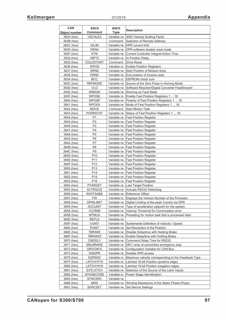
CAN
Object number
ASCII
Command
ASCII
TypeDescription
362A (hex) VSCALE2 Variable rw SW2 Velocity Scaling Factor
362B (hex) \ Command Selection of Remote Address
362C (hex) DILIM Variable rw DPR current limit
362D (hex) DENA Variable rw DPR software disable reset mode
362F (hex) KTN Variable rw Current Controller Integral-Action Time
3630 (hex) INPT0 Variable rw In-Position Delay
3632 (hex) COLDSTART Command Drive Reset
3636 (hex) WPOS Variable ro Enable Position Registers
3637 (hex) SRND Variable rw Start Position of Modulo Axes
3638 (hex) ERND Variable rw End position of modulo axes
363A (hex) BCC Variable ro EEPROM check sum
363C (hex) REFMODE Variable rw Source of the Zero Pulse in Homing Mode
363D (hex) VLO Variable rw Software Resolver/Digital Converter Feedforward
363E (hex) WMASK Variable rw Warning as Fault Mask
363F (hex) WPOSE Variable ro Enable Fast Position Registers 1 ... 16
3640 (hex) WPOSP Variable rw Polarity of Fast Position Registers 1 ... 16
3641 (hex) WPOSX Variable rw Mode of Fast Position Registers 1 ... 16
3642 (hex) MOVE Command Start Motion Task
3643 (hex) POSRSTAT Variable rw Status of Fast Position Registers 1 ... 16
3644 (hex) P1 Variable rw Fast Position Register
3645 (hex) P2 Variable rw Fast Position Register
3646 (hex) P3 Variable rw Fast Position Register
3647 (hex) P4 Variable rw Fast Position Register
3648 (hex) P5 Variable rw Fast Position Register
3649 (hex) P6 Variable rw Fast Position Register
364A (hex) P7 Variable rw Fast Position Register
364B (hex) P8 Variable rw Fast Position Register
364C (hex) P9 Variable rw Fast Position Register
364D (hex) P10 Variable rw Fast Position Register
364E (hex) P11 Variable rw Fast Position Register
364F (hex) P12 Variable rw Fast Position Register
3650 (hex) P13 Variable rw Fast Position Register
3651 (hex) P14 Variable rw Fast Position Register
3652 (hex) P15 Variable rw Fast Position Register
3653 (hex) P16 Variable rw Fast Position Register
3654 (hex) PTARGET Variable rw Last Target Position
3655 (hex) ACTRS232 Variable rw Activate RS232 Watchdog
3656 (hex) ROFFSABS Variable rw Reference Offset
3657 (hex) FW Variable ro Displays the Version Number of the Firmware
3658 (hex) DPRILIMIT Variable rw Digital Limiting of the peak Current via DPR
3659 (hex) ACCUNIT Variable rw Type of acceleration setpoint for the system
365A (hex) VCOMM Variable rw Velocity Threshold for Commutation error
365B (hex) MTMUX Variable rw Presetting for motion task that is processed later
365D (hex) REFLS Variable rw
365F (hex) VUNIT Variable rw Systemwide Definition of Velocity / Speed
3660 (hex) PUNIT Variable rw Set Resolution of the Position
366E (hex) TBRAKE Variable rw Disable Delaytime with Holding Brake
366F (hex) TBRAKE0 Variable rw Enable Delaytime with Holding Brake
3670 (hex) CMDDLY Variable rw Command Delay Time for RS232
3671 (hex) MSLBRAKE Variable rw DEC ramp at sensorless emergency stop
3672 (hex) DRVCNFG Variable rw Configuration Variable for CAN-Bus
3673 (hex) DISDPR Variable rw Disable DPR access
3675 (hex) ESPEED Variable ro Maximum velocity corresponding to the Feedback Type
367F (hex) LATCH1P16 Variable rw Latched 16-bit Position (positive edge)
3680 (hex) LATCH1N16 Variable rw Latched 16-bit Position (negative edge)
3681 (hex) EXTLATCH Variable rw Selection of the Source of the Latch Inputs
3682 (hex) STAGECODE Variable ro Power Stage Identification
3683 (hex) SYNCSRC Variable rw
3686 (hex) MRS Variable rw Winding Resistance of the Stator Phase-Phase
3691 (hex) SERCSET Variable rw Set Sercos Settings
CANopen for S300/S700 97
Kollmorgen 07/2016 Appendix

CAN
Object number
ASCII
Command
ASCII
TypeDescription
3695 (hex) SMNUMBER Variable ro Stored Motor Number in the feedback Device
3698 (hex) VREF0 Variable rw Homing Mode Reduction factor
3699 (hex) AN11NR Variable rw No. Of INxTRIG variable, that is changed analog
369A (hex) AN11RANGE Variable rw Range of the analog change of INxTRIG
36A3 (hex) MSERIALNO Variable rw Serial no of the motor for encoder feedback
36A5 (hex) VSTFR Variable rw Velocity for max. Friction Compensation
36B6 (hex) DOVRIDE Variable rw Digital Override Factor
36BE (hex) INS0 Variable ro State of Input A0 of the I/O Option Card
36BF (hex) INS1 Variable ro State of Input A1 of the I/O Option Card
36C0 (hex) INS2 Variable ro State of Input A2 of the I/O Option Card
36C1 (hex) INS3 Variable ro State of Input A3 of the I/O Option Card
36C2 (hex) INS4 Variable ro State of Input A4 of the I/O Option Card
36C3 (hex) INS5 Variable ro State of Input A5 of the I/O Option Card
36C4 (hex) INS6 Variable ro State of Input A6 of the I/O Option Card
36C5 (hex) INS7 Variable ro State of Input A7 of the I/O Option Card
36C6 (hex) INS8 Variable ro State of FSTART_IO of the I/O Option Card
36C7 (hex) OS1 Variable rw Set/Reset of "Posreg1" of the I/O Option Card
36C8 (hex) OS2 Variable rw Set/Reset of ”Posreg2" of the I/O Option Card
36C9 (hex) OS3 Variable rw Set/Reset of "Posreg3" of the I/O Option Card
36CA (hex) OS4 Variable rw Set/Reset of ”Posreg4" of the I/O Option Card
36CB (hex) OS5 Variable rw Set/Reset of "Posreg5" of the I/O Option Card
36CE (hex) LASTWMASK Variable ro Fault history of WMASK
36D0 (hex) WSTIME Variable rw Action Time of the W&S - Funktion
36D1 (hex) WSAMPL Variable rw Minimum Move of W&S Mode
36D2 (hex) NREFMT Variable rw Homing wih following motion task
36D7 (hex) AUTOHOME Variable rw
36D8 (hex) PASSCNFG Variable rw Password Function
36E4 (hex) DRVCNFG2 Variable rw Additional drive functions
36E5 (hex) BUSP1 Variable rw State of the Modbus+ Network
36E6 (hex) BUSP2 Variable rw Number of Data Words (Command) at Modbus+
36E7 (hex) BUSP3 Variable rw Address selection of Modbus+
36E8 (hex) BUSP4 Variable rw Number of Data Words (Command) at Modbus+
36E9 (hex) BUSP5 Variable rw Number of Data Words (Command) at Modbus+
36EA (hex) BUSP6 Variable rw Number of Actual Value Data Words via Modbus
3890 (hex) CSSTAT Variable ro Status (see SDO 2401h, p. 107)
3891 (hex) CSIOSTAT Variable ro Status (see SDO 2402h, p. 108)
3892 (hex) CSERR Variable ro Status (see SDO 2403h, p. 109)
3893 (hex) FBGEARI Variable rw compensation factor motor/gearing
3894 (hex) FBGEARO Variable rw compensation factor motor/gearing
3895 (hex) BCCOT Variable ro EEPROM check sum without life time counter
3896 (hex) HLIMIT1 Variable rw Software limit switch 1 for homing move
3897 (hex) HLIMIT2 Variable rw Software limit switch 2 for homing move
3898 (hex) HLIMIT3 Variable rw Software limit switch 3 for homing move
3899 (hex) PASSPLC Variable rw Password value for PLC commands
389A (hex) PASSXPLC Variable rw Password configuration for PLC commands
389B (hex) PTARGOFFS Variable rw Motion tasks position target shift
389C (hex) RSVERROFF Variable rw Resolver error supervision off
389D (hex) DIRIN Variable rw polarity of the digital inputs
389E (hex) RELTIME Variable rw switching on of the thyristor voltage control
38A0 (hex) ANIN3 Variable ro Voltage at analog input 3 (POS I/O)
38A1 (hex) ANIN4 Variable ro Voltage at analog input 4 (POS I/O)
38A2 (hex) ANOFF3 Variable rw Analog offset for analog input 3 (POS I/O)
38A3 (hex) ANOFF4 Variable rw Analog offset for analog input 4 (POS I/O)
38A4 (hex) ANZERO3 Command Zero analog input 3 (POS I/O)
38A5 (hex) ANZERO4 Command Zero analog input 4 (POS I/O)
38A6 (hex) CALCPOSIO Command Initialisation of the POS I/O card
38A7 (hex) GPTNTH1 Variable rw integral part threshold for velocity set point
38A7 (hex) GPTNTH2 Variable rw integral part threshold for velocity actual value
36CC (hex) GPTNTH3 Variable rw integral part threshold for following error
38AF (hex) GPDELAY Variable rw delay for external position set point
98 CANopen for S300/S700
Appendix 07/2016 Kollmorgen

CAN
Object number
ASCII
Command
ASCII
TypeDescription
38B1 (hex) GPTN Variable rw integral gain of the PI position loop
38B2 (hex) GPTN_X Variable rw integral gain of the PI position loop
38B3 (hex) MAXISETP Variable rw limitation of the integral part of the position loop
38B4 (hex) MAXVSETP Variable rw Limitation of the proportional part of the position loop
38B7 (hex) BISSCNFG Variable rw configuration parameter for BiSS-C
38B9 (hex) S1DLY Variable rw switch-on delay
38BB (hex) TEMPMFILT Variable rw time constant for the filter of motor temperature sensors
38BE (hex) EWH Variable rw consumed electric energy in watt-hours
38BF (hex) VBUSBOFFS Variable rw abatement of the Regen switch on threshold
38C0 (hex) VLO_X Variable rw Software resolver/digital converter feedforward
38C1 (hex) VBUSRAMP Variable rw switching on threshold for the braking ramp control
38C2 (hex) VBUSFACT Variable rw gain factor for the deceleration ramp control
38C3 (hex) GP2 Variable rw proportional gain for the velocity higher than GPS2
38C4 (hex) GPS1 Variable rw low velocity threshold (position loop)
38C5 (hex) GPS2 Variable rw high velocity threshold (position loop)
38C6 (hex) GV2 Variable rw proportional gain for the velocity higher than GVS2
38C7 (hex) GVS1 Variable rw low velocity threshold (velocity loop)
38C8 (hex) GVS2 Variable rw high velocity threshold (velocity loop)
38CA (hex) CSCNFG Variable rw Configuration Variable for safety card
38CB (hex) CSENID Variable rw reactive current impression
38CC (hex) CSIDMAX Variable rw Maximum value for reactive current command
38CE (hex) DRVCNFG4 Variable rw Configuration parameter for additional drive functionality
38CF (hex) MVANGLMODE Variable rw S600 compatibility mode for speed dependend phase lead
38D0 (hex) VBUSOFFS Variable rw correction value for the regen threshold S748/772
38D1 (hex) PMECH Variable ro estimated mechanical power delivered by the motor
38D2 (hex) P Variable ro calculated active power (electrical)
38D3 (hex) ENCFIX Variable rw Decimal places for the ENCLINES parameter
38D5 (hex) LINRESOL Variable rw Conversion factor for linear measurement systems
38D6 (hex) ENCDIV Variable rw Divisor for the decimal places of ENCLINE
38D7 (hex) QCNFG Variable rw Configuration for the servo pump function
38D8 (hex) QFACTOR Variable rw Swallowing capacity for the servo pump function
38D9 (hex) QFCFACT Variable ro Swallowing capacity for the servo pump function
38DA (hex) QMACT Variable ro Actual torque value for servo pump function
38DB (hex) QTVEFF Variable ro Actual D-part for the servo pump control loop
38DD (hex) QFSET Variable ro flow set point for servo pump (filtered)
38DE (hex) QFACT Variable ro Flow actual value for servo pump
38DF (hex) QPRSET Variable rw Pressure set point for servo pump
38E0 (hex) QPRACT Variable ro Pressure actual value for servo pump
38E1 (hex) QMCMD Variable ro Actual torque set point value for servo pump
38E2 (hex) QFACTCOMP Variable ro Flow actual value for servo pump (compensated)
38E3 (hex) QFACTFILT Variable ro Flow actual value for servo pump (filtered)
38E4 (hex) QTIMEKD Variable rw Time constant of the D-Part for the servo pump loop
38E5 (hex) QVT1 Variable rw Time constant of the flow filter for the servo pump
38E6 (hex) QMCMDLIM Variable ro Actual torque set point for the servo pump (after limitation)
38E7 (hex) QMLIMP Variable rw Torque limitation for servo pump (pressure build-up)
38E9 (hex) QFMAX Variable rw Max. flow max. set point value for servo pump
38EA (hex) QPRMAX Variable rw Max. pressure set point for servo pump
38EB (hex) QTAB1KP Variable rw Proportional gain 1 for servo pump loop
38EC (hex) QTAB2KP Variable rw Proportional gain 2 for servo pump loop
38ED (hex) QTAB3KP Variable rw Proportional gain 3 for servo pump loop
38EE (hex) QTAB4KP Variable rw Proportional gain 4 for servo pump loop
38EF (hex) QTAB5KP Variable rw Proportional gain 5 for servo pump loop
38F0 (hex) QTAB1V Variable rw Velocity threshold 1 for servo pump loop
38F1 (hex) QTAB2V Variable rw Velocity threshold 2 for servo pump loop
38F2 (hex) QTAB3V Variable rw Velocity threshold 3 for servo pump loop
38F3 (hex) QTAB4V Variable rw Velocity threshold 4 for servo pump loop
38F4 (hex) QTAB5V Variable rw Velocity threshold 5 for servo pump loop
38F5 (hex) QTAB1TN Variable rw Integral gain 1 for servo pump loop
38F6 (hex) QTAB2TN Variable rw Integral gain 2 for servo pump loop
38F7 (hex) QTAB3TN Variable rw Integral gain 3 for servo pump loop
CANopen for S300/S700 99
Kollmorgen 07/2016 Appendix

CAN
Object number
ASCII
Command
ASCII
TypeDescription
38F8 (hex) QTAB4TN Variable rw Integral gain 4 for servo pump loop
38F9 (hex) QTAB5TN Variable rw Integral gain 5 for servo pump loop
38FA (hex) QPE Variable ro Pressure following error for servo pump loop
38FB (hex) QKPEFF Variable ro Actual proportional gain for the servo pump loop
38FC (hex) QTNEFF Variable ro Actual integral gain for the servo pump loop
38FD (hex) GVTV Variable rw Derivative time for the velocity loop
38FE (hex) GVTV_X Variable rw Derivative time for the velocity loop (second parameter set)
3900 (hex) QTABID Variable ro Actual gain set for servo pump loop
3901 (hex) QTAB1TV Variable rw Derivative time 1 for servo pump loop
3902 (hex) QTAB2TV Variable rw Derivative time 2 for servo pump loop
3903 (hex) QTAB3TV Variable rw Derivative time 3 for servo pump loop
3904 (hex) QTAB4TV Variable rw Derivative time 4 for servo pump loop
3905 (hex) QTAB5TV Variable rw Derivative time 5 for servo pump loop
3907 (hex) GFTN Variable rw time constant flow controlinduction maschine)
3908 (hex) MCFW Variable rw The Correction Factor of the Field Weakening
3909 (hex) ENCDIVD Variable rw Divisor for the decimal places of ENCIN
390A (hex) ENCFIXD Variable rw Decimal places for the ENCIN parameter
390B (hex) SSITIME Variable rw SSI setting time
390C (hex) SSIMASK Variable rw Filter mask for received SSI data
390D (hex) EN22A1CNT Variable ro ENDAT2.2 state of the additional information 1
390E (hex) EN22A2CNT Variable ro ENDAT2.2 state of the additional information 2
390F (hex) EN22CNFG Variable rw ENDAT2.2 configuration parameter for diagnosis information
3910 (hex) EN22DCNT Variable ro ENDAT2.2 status for diagnosis information
3911 (hex) GV2_X Variable rw proportional gain for the velocity higher than GVS2
3912 (hex) ZEROTIME Variable rw Default value for the ZERO function
3913 (hex) QENA Variable rw Enable/disable servo pump function
3914 (hex) QFCMD Variable rw flow set point for servo pump (unfiltered)
3916 (hex) QT1 Variable rw Flow filter time for servo pump
3917 (hex) QMLIMN Variable rw Torque limitation for servo pump (pressure reduction)
3918 (hex) HDSLTEMP Variable ro Motor/encoder temperature read from the HIPERFACE DSL
3919 (hex) HDSLLED Variable ro LED current from HIPERFACE DSL
391A (hex) HDSLVOLT Variable ro Voltage supply from the HIPERFACE DSL
391B (hex) HDSLVEL Variable ro Actual velocity taken from the HIPERFACE DSL
391C (hex) HDSLTIME Variable ro Operation-hour counter taken from HIPERFACE DSL
391D (hex) HDSLROTAT Variable ro Rotation counter taken from HIPERFACE DSL
100 CANopen for S300/S700
Appendix 07/2016 Kollmorgen

5.1.3 Object Dictionary
IndexSub-
IndexData Type Access
PDO
mapp.Description
ASCII
object
1000h 0 UNSIGNED32 ro — Device type —
1001h 0 UNSIGNED8 ro — Error register —
1002h 0 UNSIGNED32 ro yes Manufacturer—specific status register —
1003h
ARRAY Pre—defined error field —
0 UNSIGNED8 rw — Number of errors —
1...8 UNSIGNED32 ro — standard error field —
1005h 0 UNSIGNED32 rw — COB—ID SYNC message —
1006h 0 UNSIGNED32 rw No Communication cycle period —
1008h 0 Visible String const — Manufacturer device name —
1009h 0 Visible String const — Manufacturer hardware version —
100Ah 0 Visible String const — Manufacturer software version —
100Ch 0 UNSIGNED16 rw — Guard time —
100Dh 0 UNSIGNED8 rw — Lifetime factor —
1010h0 UNSIGNED8 ro — Number of entries —
1 UNSIGNED32 rw — Save all parameters SAVE
1011h0 UNSIGNED8 ro — Number of entries —
1 UNSIGNED32 rw — Restore all default parameters RSTVAR
1014h 0 UNSIGNED32 rw — COB—ID for the Emergency Object —
1016h
RECORD Consumer heartbeat time
0 UNSIGNED8 ro — Number of entries —
1 UNSIGNED32 rw — Consumer heartbeat time —
1017h 0 UNSIGNED16 rw — Producer heartbeat time —
1018h
RECORD Identity Object —
0 UNSIGNED8 ro — Number of entries —
1 UNSIGNED32 ro — Vendor ID —
2 UNSIGNED32 ro — Product Code —
3 UNSIGNED32 ro — Revision number —
4 UNSIGNED32 ro — Serial number SERIALNO
1026h
ARRAY OS prompt —
0 UNSIGNED8 ro — Number of entries —
1 UNSIGNED8 w — StdIn —
2 UNSIGNED8 ro — StdOut —
1400h
RECORD RXPDO1 communication parameter —
0 UNSIGNED8 ro — Number of entries —
1 UNSIGNED32 rw — RXPDO1 COB — ID —
2 UNSIGNED8 rw — Transmission type RXPDO1 —
1401h
RECORD RXPDO2 communication parameter —
0 UNSIGNED8 ro — Number of entries —
1 UNSIGNED32 rw — RXPDO2 COB — ID —
2 UNSIGNED8 rw — Transmission type RXPDO2 —
1402h
RECORD RXPDO3 communication parameter —
0 UNSIGNED8 ro — Number of entries —
1 UNSIGNED32 rw — RXPDO3 COB — ID —
2 UNSIGNED8 rw — Transmission type RXPDO3 —
1403h
RECORD RXPDO4 communication parameter —
0 UNSIGNED8 ro — Number of entries —
1 UNSIGNED32 rw — RXPDO4 COB — ID —
2 UNSIGNED8 rw — Transmission type RXPDO4 —
1600h
RECORD RXPDO1 mapping parameter —
0 UNSIGNED8 ro — Number of entries —
1...8 UNSIGNED32 rw — Mapping for n—th application object —
1601h
RECORD RXPDO2 mapping parameter —
0 UNSIGNED8 ro — Number of entries —
1...8 UNSIGNED32 rw — Mapping for n—th application object —
1602h
RECORD RXPDO3 mapping parameter —
0 UNSIGNED8 ro — Number of entries —
1...8 UNSIGNED32 rw — Mapping for n—th application object —
CANopen for S300/S700 101
Kollmorgen 07/2016 Appendix

IndexSub-
IndexData Type Access
PDO
mapp.Description
ASCII
object
1603h
RECORD RXPDO4 mapping parameter —
0 UNSIGNED8 ro — Number of entries —
1...8 UNSIGNED32 rw — Mapping for n—th application object —
1800h
RECORD TXPDO1 communication parameter —
0 UNSIGNED8 ro — Number of entries —
1 UNSIGNED32 rw — TXPDO1 COB—ID —
2 UNSIGNED8 rw — Transmission type TXPDO1 —
3 UNSIGNED16 rw — Inhibit time —
4 UNSIGNED8 const — reserved —
5 UNSIGNED16 rw — event timer —
1801h
RECORD TXPDO2 communication parameter —
0 UNSIGNED8 ro — Number of entries —
1 UNSIGNED32 rw — TXPDO2 COB—ID —
2 UNSIGNED8 rw — Transmission type TXPDO2 —
3 UNSIGNED16 rw — Inhibit time —
4 UNSIGNED8 const — reserved —
5 UNSIGNED16 rw — event timer —
1802h
RECORD TXPDO3 communication parameter —
0 UNSIGNED8 ro — Number of entries —
1 UNSIGNED32 rw — TXPDO3 COB—ID —
2 UNSIGNED8 rw — Transmission type TXPDO3 —
3 UNSIGNED16 rw — Inhibit time —
4 UNSIGNED8 const — reserved —
5 UNSIGNED16 rw — event timer —
1803h
RECORD TXPDO4 communication parameter —
0 UNSIGNED8 ro — Number of entries —
1 UNSIGNED32 rw — TXPDO4 COB—ID —
2 UNSIGNED8 rw — Transmission type TXPDO4 —
3 UNSIGNED16 rw — Inhibit time —
4 UNSIGNED8 const — reserved —
5 UNSIGNED16 rw — event timer —
1A00h
RECORD Mapping parameter TXPDO1 —
0 UNSIGNED8 ro — Number of entries —
1...8 UNSIGNED32 rw — Mapping for n—th application object —
1A01h
RECORD Mapping parameter TXPDO2 —
0 UNSIGNED8 ro — Number of entries —
1...8 UNSIGNED32 rw — Mapping for n—th application object —
1A02h
RECORD Mapping parameter TXPDO3 —
0 UNSIGNED8 ro — Number of entries —
1...8 UNSIGNED32 rw — Mapping for n—th application object —
1A03h
RECORD Mapping parameter TXPDO4 —
0 UNSIGNED8 ro — Number of entries —
1...8 UNSIGNED32 rw — Mapping for n—th application object —
2000h 0 UNSIGNED32 ro yes Manufacturer warnings STATCODE
2014h
0 ARRAY ro — Mask TxPDO Channel 1 —
1 UNSIGNED32 rw — Mask (Byte 0..3) —
2 UNSIGNED32 rw — Mask (Byte 4..7) —
2015h
0 ARRAY ro — Mask TxPDO Channel 2 —
1 UNSIGNED32 rw — Mask (Byte 0..3) —
2 UNSIGNED32 rw — Mask (Byte 4..7) —
2016h
0 ARRAY ro — Mask TxPDO Channel 3 —
1 UNSIGNED32 rw — Mask (Byte 0..3) —
2 UNSIGNED32 rw — Mask (Byte 4..7) —
2017h
0 ARRAY ro — Mask TxPDO Channel 4 —
1 UNSIGNED32 rw — Mask (Byte 0..3) —
2 UNSIGNED32 rw — Mask (Byte 4..7) —
102 CANopen for S300/S700
Appendix 07/2016 Kollmorgen

IndexSub-
IndexData Type Access
PDO
mapp.Description
ASCII
object
2030h
ARRAY DP-Ram Variablen, write only (PDO) -
0 UNSIGNED8 ro - Anzahl der Einträge -
1 INTEGER32 rww yes DP-Ram Variable 9 DPRVAR9
2 INTEGER32 rww yes DP-Ram Variable 10 DPRVAR10
3 INTEGER32 rww yes DP-Ram Variable 11 DPRVAR11
4 INTEGER32 rww yes DP-Ram Variable 12 DPRVAR12
5 INTEGER32 rww yes DP-Ram Variable 13 DPRVAR13
6 INTEGER32 rww yes DP-Ram Variable 14 DPRVAR14
7 INTEGER32 rww yes DP-Ram Variable 15 DPRVAR15
8 INTEGER32 rww yes DP-Ram Variable 16 DPRVAR16
2040h
RECORD Gearing factors for electronic gearing —
0 UNSIGNED8 — Number of entries —
1 INTEGER32 rw yes input factor for electronic gearing GEARI
2 UNSIGNED32 rw yes output factor for electronic gearing GEARO
2041h
RECORD Actual values electr. gearing -
0 UNSIGNED8 ro - Number of entries -
1 INTEGER32 ro yes Slave velocity set point -
2 INTEGER32 ro yes Master velocity -
3 UNSIGNED8 ro yes Internal control word for electr. gearing -
2051h
ARRAY Configuration of Position Registers -
0 UNSIGNED8 ro - Number of entries -
1 UNSIGNED32 rww yes Position register Enable WPOSE
2 UNSIGNED32 rww yes Position register Mode WPOSX
3 UNSIGNED32 rww yes Polarity of the position registers WPOSP
2052h
ARRAY Position registers, absolute -
0 UNSIGNED8 ro - Number of entries -
1 INTEGER32 rww yes Position register 1, absolute P1
2 INTEGER32 rww yes Position register 2, absolute P2
3 INTEGER32 rww yes Position register 3, absolute P3
4 INTEGER32 rww yes Position register 4, absolute P4
5 INTEGER32 rww yes Position register 5, absolute P5
6 INTEGER32 rww yes Position register 6, absolute P6
7 INTEGER32 rww yes Position register 7, absolute P7
8 INTEGER32 rww yes Position register 8, absolute P8
9 INTEGER32 rww yes Position register 9, absolute P9
10 INTEGER32 rww yes Position register 10, absolute P10
11 INTEGER32 rww yes Position register 11, absolute P11
12 INTEGER32 rww yes Position register 12, absolute P12
13 INTEGER32 rww yes Position register 13, absolute P13
14 INTEGER32 rww yes Position register 14, absolute P14
15 INTEGER32 rww yes Position register 15, absolute P15
16 INTEGER32 rww yes Position register 16, absolute P16
2053h
ARRAY Position registers, relative -
0 UNSIGNED8 ro - Number of entries -
1 INTEGER32 rww yes Position register 1, relative P1
2 INTEGER32 rww yes Position register 2, relative P2
3 INTEGER32 rww yes Position register 3, relative P3
4 INTEGER32 rww yes Position register 4, relative P4
5 INTEGER32 rww yes Position register 5, relative P5
6 INTEGER32 rww yes Position register 6, relative P6
7 INTEGER32 rww yes Position register 7, relative P7
8 INTEGER32 rww yes Position register 8, relative P8
9 INTEGER32 rww yes Position register 9, relative P9
10 INTEGER32 rww yes Position register 10, relative P10
11 INTEGER32 rww yes Position register 11, relative P11
12 INTEGER32 rww yes Position register 12, relative P12
13 INTEGER32 rww yes Position register 13, relative P13
14 INTEGER32 rww yes Position register 14, relative P14
15 INTEGER32 rww yes Position register 15, relative P15
16 INTEGER32 rww yes Position register 16, relative P16
2061h 0 UNSIGNED16 rww yes Current limitation for velocity mode DPRILIMIT
CANopen for S300/S700 103
Kollmorgen 07/2016 Appendix

IndexSub-
IndexData Type Access
PDO
mapp.Description
ASCII
object
2080h 0 UNSIGNED16 rw yes Motion task for profile position mode —
2081h 0 UNSIGNED16 rw yes Active motion task display MOVE
2082h 0 UNSIGNED32 wo — Copy motion task OCOPY
2083h 0 UNSIGNED32 wo — Erase flash motion tasks —
2090h
ARRAY DP-Ram Variables, read only -
0 UNSIGNED8 ro - Number of entries -
1 INTEGER32 ro yes DP-Ram Variable 1 DPRVAR1
2 INTEGER32 ro yes DP-Ram Variable 2 DPRVAR2
3 INTEGER32 ro yes DP-Ram Variable 3 DPRVAR3
4 INTEGER32 ro yes DP-Ram Variable 4 DPRVAR4
5 INTEGER32 ro yes DP-Ram Variable 5 DPRVAR5
6 INTEGER32 ro yes DP-Ram Variable 6 DPRVAR6
7 INTEGER32 ro yes DP-Ram Variable 7 DPRVAR7
8 INTEGER32 ro yes DP-Ram Variable 8 DPRVAR8
20A0h 0 INTEGER32 ro yes Latch position 1, positive edge LATCH1P32
20A1h 0 INTEGER32 ro yes Latch position 1, negative edge LATCH1N32
20A2h 0 INTEGER32 ro yes Latch position 2, positive edge LATCH2P32
20A3h 0 INTEGER32 ro yes Latch position 2, negative edge LATCH2N32
20A4h 0 UNSIGNED8 rww yes Latch control register -
20B0h 0 INTEGER32 rww yes Trigger variable digital input 20 IN20TRIG
20B1h 0 UNSIGNED32 rww yes Controlword digital inputs 5 .. 20 IN5 .. IN20
20B2h
ARRAY Analog Inputs -
0 UNSIGNED8 ro — Number of entries -
1 INTEGER16 ro yes Voltage analog input 1 ANIN1
2 INTEGER16 ro yes Voltage analog input 2 ANIN2
2100h 0 UNSIGNED32 rww yes Write Dummy -
2101h 0 UNSIGNED32 ro yes Read Dummy -
2400h
RECORD Safety card serial number —
0 UNSIGNED8 ro — Number of entries —
1-6 UNSIGNED32 ro — Safety card serial number part 1-6 —
2401h 0 UNSIGNED32 ro yes Safety card status CSSTAT
2402h 0 UNSIGNED32 ro yes Safety card I/O status CSIOSTAT
2403h 0 UNSIGNED32 ro yes Safety card error register CSERR
2404h
RECORD Safety card error stack error number —
0 UNSIGNED8 ro — Number of entries —
1-128 UNSIGNED32 ro — Error Stack – Error Number 1...128 —
2405h
RECORD Fehlerstack – Error Time —
0 UNSIGNED8 ro — Number of entries —
1-128 UNSIGNED32 ro — Error Stack – Error Time 1...128 —
2406h
RECORD Fehlerstack – Error Index —
0 UNSIGNED8 ro — Number of entries —
1-128 UNSIGNED32 ro — Error Stack – Error Index 1...128 —
2407h
RECORD Error Stack – Error Info —
0 UNSIGNED8 ro — Number of entries —
1-128 UNSIGNED32 ro — Error Stack – Error Info 1...128 —
2408h
RECORD Error Stack – Error Parameter 1 —
0 UNSIGNED8 ro — Number of entries —
1-128 UNSIGNED32 ro — Error Stack – Parameter 1 Error 1...128 —
2409h
RECORD Error Stack – Error Parameter 2 —
0 UNSIGNED8 ro — Number of entries —
1-128 UNSIGNED32 ro — Error Stack – Parameter 2 Error 1...128 —
240Ah
RECORD Error Stack – Error Parameter 3 —
0 UNSIGNED8 ro — Number of entries —
1-128 UNSIGNED32 ro — Error Stack – Parameter 3 Error 1...128 —
240Bh
RECORD Error Stack – Error Parameter 4 —
0 UNSIGNED8 ro — Number of entries —
1-128 UNSIGNED32 ro — Error Stack – Parameter 4 Error 1...128 —
240Ch 0 UNSIGNED32 ro yes Safety card actual speed —
104 CANopen for S300/S700
Appendix 07/2016 Kollmorgen

IndexSub-
IndexData Type Access
PDO
mapp.Description
ASCII
object
3500h
RECORD ASCII Command MAXCMD MAXCMD
0 UNSIGNED8 ro — Number of entries —
1 UNSIGNED32 ro — Value —
2 UNSIGNED32 ro — Lower limit value —
3 UNSIGNED32 ro — Upper limit value —
4 UNSIGNED32 ro — Default value —
5 UNSIGNED32 ro — Parameter format —
6 UNSIGNED32 ro — Parameter control data —
7 UNSIGNED32 ro — reserved —
8 UNSIGNED32 ro — reserved —
3500h+MAXCMD RECORD Last entry of the ASCII Object Chanel —
6040h 0 UNSIGNED16 w yes control word —
6041h 0 UNSIGNED16 ro yes status word —
6060h 0 INTEGER8 rw yes Modes of Operation —
6061h 0 INTEGER8 ro yes Modes of Operation Display —
6063h 0 INTEGER32 ro yes Position actual value (increments) —
6064h 0 INTEGER32 ro yes Position actual value (position units) PFB
6065h 0 UNSIGNED32 rw — Following error window PEMAX
6067h 0 UNSIGNED32 rw — Position window PEINPOS
6068h 0 UNSIGNED16 rw — Position window time INPT1
606Ch 0 INTEGER32 ro yes Velocity actual value —
6071h 0 INTEGER16 rw yes Target torque —
6073h 0 UNSIGNED16 rw — Max current MIPEAK
6077h 0 INTEGER16 ro yes Torque actual value —
607Ah 0 INTEGER32 rw yes Target position O_P
607Ch 0 INTEGER32 rw — Reference offset ROFFS
607Dh
ARRAY Software position limit
0 UNSIGNED8 ro — Number of entries
1 INTEGER32 rw — Software position limit 1 SWE1
2 INTEGER32 rw — Software position limit 2 SWE2
607Fh 0 UNSIGNED32 rw — Max profile velocity PVMAX
6080h 0 UNSIGNED32 rw — Max motor speed VLIM
6081h 0 UNSIGNED32 rw yes Profile Velocity O_V
6083h 0 UNSIGNED32 rw yes Profile AccelerationO_ACC (pp)
/ACC (pv)
6084h 0 UNSIGNED32 rw yes Profile DecelerationO_DEC (pp) /
DEC (pv)
6085h 0 UNSIGNED32 rw — Quick stop deceleration DECSTOP
6086h 0 INTEGER16 Rww yes Motion profile type O_C
6089h 0 INTEGER8 rw — Position Notation index —
608Ah 0 UNSIGNED8 rw — Position Dimension index —
608Bh 0 INTEGER8 rw — Velocity Notation index —
608Ch 0 UNSIGNED8 rw — Velocity Dimension index —
608Dh 0 INTEGER8 rw — Acceleration Notation index —
608Eh 0 UNSIGNED8 rw — Acceleration Dimension index —
608Fh
ARRAY Position encoder resolution —
0 UNSIGNED8 ro — Number of entries —
1 UNSIGNED32 rw — Encoder increments PGEARO
2 UNSIGNED32 rw — Motor revolutions BUSP7
6090h
ARRAY Velocity encoder resolution —
0 UNSIGNED8 ro — Number of entries —
1 UNSIGNED32 rw — Encoder increments per second —
2 UNSIGNED32 rw — Motor revolutions per second —
6091h
ARRAY Gear ratio —
0 UNSIGNED8 ro — Number of entries —
1 UNSIGNED32 rw — Motor revolutions —
2 UNSIGNED32 rw — Shaft revolutions —
6092h
ARRAY Feed constant —
0 UNSIGNED8 ro — Number of entries —
1 UNSIGNED32 rw — Feed PGEARI
2 UNSIGNED32 rw — Shaft revolutions —
CANopen for S300/S700 105
Kollmorgen 07/2016 Appendix

IndexSub-
IndexData Type Access
PDO
mapp.Description
ASCII
object
6093h
ARRAY Position factor —
0 UNSIGNED8 ro — Number of entries —
1 UNSIGNED32 rw — Numerator —
2 UNSIGNED32 rw — Feed constant —
6094h
ARRAY Velocity encoder factor —
0 UNSIGNED8 ro — Number of entries —
1 UNSIGNED32 ro — Numerator —
2 UNSIGNED32 ro — Denumerator —
6097h
ARRAY Acceleration factor —
0 UNSIGNED8 ro Number of entries —
1 UNSIGNED32 rw — Numerator —
2 UNSIGNED32 rw — Denumerator —
6098h 0 INTEGER8 rw — Homing type NREF, DREF
6099h
ARRAY Homing velocity —
0 UNSIGNED8 ro — Number of entries —
1 UNSIGNED32 rw — Speed while searching for limit switch VREF
2 UNSIGNED32 rw — Speed while searching for zero mark VREF0
609Ah 0 UNSIGNED32 rw — Homing acceleration ACCR, DECR
60C0h 0 INTEGER8 rw — Interpolation submode select —
60C1h
ARRAY Interpolation data record —
0 UNSIGNED8 ro — Number of entries —
1 INTEGER32 rw yes x1, first parameter of ip function —
60C2h
RECORD Interpolation time period —
0 UNSIGNED8 ro — Number of entries PTBASE
1 UNSIGNED8 rw — Interpolation time units —
2 INTEGER16 rw — Interpolation time index —
60C3h
ARRAY Interpolation sync definition —
0 UNSIGNED8 ro — Number of entries —
1 UNSIGNED8 rw — Synchronize on group —
2 UNSIGNED8 rw — ip sync every n event —
60C4h
RECORD Interpolation data configuration —
0 UNSIGNED8 ro — Number of entries —
1 UNSIGNED32 ro — Maximum buffer size —
2 UNSIGNED32 rw — Actual buffer size —
3 UNSIGNED8 rw — Buffer organization —
4 UNSIGNED16 rw — Buffer position —
5 UNSIGNED8 w — Siza of data record —
60C5h 0 UNSIGNED32 rw — Max acceleration /deceleration —
60C4h 6 UNSIGNED8 w — Buffer clear —
60F4h 0 INTEGER32 ro yes Following error actual value PE
60FDh 0 UNSIGNED32 ro yes Digital inputs IN1 .. IN4
60FFh 0 INTEGER32 rw yes Target velocity J
6502h 0 UNSIGNED32 ro — Supported drive modes —
106 CANopen for S300/S700
Appendix 07/2016 Kollmorgen

5.2 CANopen SDOs for Safety Expansion Card S1/S2/S1-2/S2-2
The Safety expansion cards S1, S2, S3, S4 can be used with S700 from Hardware Revision 2.10
only.
5.2.1 Object 2400h: Safety card serial number
The serial number of the safety card must be filled in the configurator software. The number is prin-
ted on the safety card front cover. It is separated to six 32 bit blocks, every byte codes one ASCII
character. End of string is coded by 0h.
Index 2400h
Name Safety card serial number
Object code Record
Category optional
Subindex 0
Description number of entries
Data type UNSIGNED8
Category optional
Access ro
PDO mapping not possible
Value range 6
Default value 6
Subindex 1 to 6
Description Safety card serial number part 1 to 6
Data type UNSIGNED32
Category optional
Access ro
PDO mapping not possible
Value range UNSIGNED32
Default value —
5.2.2 Object 2401h: Safety card status
Index 2401h
Name Safety card status
Object code VAR
Data type UNSIGNED32
Category optional
Access ro
PDO mapping possible
Value range UNSIGNED32
Default value —
Bit Meaning
0 Status LED ‘POWER’ on safety card front cover
1 Status LED ‘RUN’ on safety card front cover
2 Status LED ‘CONFIG’ on safety card front cover
3 Status LED ‘FAULT’ on safety card front cover
4 Status internal ‘STO’ (0 = STO not active, 1 = STO active)
5 OK message if configuration data download was successful
8 Bit is set if safety card status is ‘STARTUP’
9 Bit is set if safety card status is ‘RUN’
10 Bit is set if safety card status is ‘STOP’
11 Bit is set if safety card status is ‘CONFIG’
CANopen for S300/S700 107
Kollmorgen 07/2016 Appendix

5.2.3 Object 2402h: Safety card I/O status
Index 2402h
Name Safety card I/O status
Object code VAR
Data type UNSIGNED32
Category optional
Access ro
PDO mapping possible
Value range UNSIGNED32
Default value —
Bit Meaning
0 Status input ‘SS1 Activate’
1 Status input ‘SS2 Activate’
2 Status input ‘SOS Activate’
3 Status input ‘SLS Activate’
4 Status input ‘SSR Activate’
5 Status input ‘SDI Left Activate’
6 Status input ‘SDI Right Activate’
7 Status input ‘SBT Activate’
8 Status output ‘Ready’
9 Status output ‘STO Acknowledge’
10 Status output ‘SOS Acknowledge’
11 Status output ‘SDI Acknowledge’
12 Status output ‘Safe Range Acknowledge’
13 Status output ‘SBT Acknowledge’
14 Status 2 pole output ‘Safe Brake Control’ (external brake)
15 Status output ‘STO SIL3’ (second switch off line)
16 Status input ‘SS1 SIL3/Reset’
29 Brake ramp control SS2 (0=drive control, 1=PLC control)
30 Brake ramp control SS1 (0=drive control, 1=PLC control)
31 Emergency stop ramp with SS1 (0=not active, 1=active)
108 CANopen for S300/S700
Appendix 07/2016 Kollmorgen

5.2.4 Object 2403h: Safety card error register
Index 2403h
Name Safety card error register
Object code VAR
Data type UNSIGNED32
Category optional
Access ro
PDO mapping possible
Value range UNSIGNED32
Default value 0
Bit Meaning
0 Error with safety function ‘Safe Stop 1’ SS1
1 Error with safety function ‘Safe Stop 2’ SS2
2 Error with safety function ‘Safe Operating Stop’ SOS
3 Error with safety function ‘Safely Limited Speed’ SLS
4 Error with safety function ‘Safe Speed Range’ SSR
5 Error with safety function ‘Safe Direction’ SDI
6 Error with safety function ‘Safe Brake Test’ SBT
11 Error with wiring of digital inputs
12 Error wiring / feedback digital outputs
13 Error with voltage supervision test
14 Error with watchdog test (start, stop)
15 Error with memory test (Flash/RAM)
16 Timing error (interrupt supervision)
17 Position supervision by current signal
18 Position supervision by feedback signal (internal, external, set point)
19 Parameter error (servo amplifier)
20 Input states / configuration data don't match to each other
21 Error data check Channel A-B
24 Error with write/delete in flash memory
25 Time synchronization of channels A and B
26 Watchdog triggered
27 Data / parameter check (data transmission / configuration)
28 Timeout during transmission of data/parameter
29 Error CRC check
30 Error device data check (serial numkber, version)
31 Fatal error system software
CANopen for S300/S700 109
Kollmorgen 07/2016 Appendix

5.2.5 Object 2404h: Safety card error stack error number
Error numbers of the entries.
The error stack can be requested by SDOs 2404h to 240Bh. Identical subindices always corre-
sponds to each other. A complete entry would be for example 2404h to 240Bh alweays with subin-
dex 5.
Index 2404h
Name Safety card error stack error number
Object code Record
Category optional
Subindex 0
Description number of entries
Data type UNSIGNED8
Category optional
Access ro
PDO mapping not possible
Value range 0...128
Default value 0
Subindex 1 to 128
Description Safety card error stack error number X
Data type UNSIGNED32
Category optional
Access ro
PDO mapping not possible
Value range UNSIGNED32
Default value 0
5.2.6 Object 2405h: Safety card error stack error time
Time index were the error occured.
Index 2405h
Name Safety card error stack error time
Object code Record
Category optional
Subindex 0
Description number of entries
Data type UNSIGNED8
Category optional
Access ro
PDO mapping not possible
Value range 0...128
Default value 0
Subindex 1 to 128
Description Safety card error stack error time X
Data type UNSIGNED32
Category optional
Access ro
PDO mapping not possible
Value range UNSIGNED32
Default value 0
110 CANopen for S300/S700
Appendix 07/2016 Kollmorgen

5.2.7 Object 2406h: Safety card error stack error index
Detailled error code (suberror code)-
Index 2406h
Name Safety card error stack error index
Object code Record
Category optional
Subindex 0
Description number of entries
Data type UNSIGNED8
Category optional
Access ro
PDO mapping not possible
Value range 0...128
Default value 0
Subindex 1 to 128
Description Safety card error stack error index X
Data type UNSIGNED32
Category optional
Access ro
PDO mapping not possible
Value range UNSIGNED32
Default value 0
5.2.8 Object 2407h: Safety card error stack error info
Indicates the channel were the error occurd and tghe current error state:
Bit 0 = Channel A
Bit 1 = Channel B
Bit 2 = Error still occurs
Index 2407h
Name Safety card error stack error info
Object code Record
Category optional
Subindex 0
Description number of entries
Data type UNSIGNED8
Category optional
Access ro
PDO mapping not possible
Value range 0...128
Default value 0
Subindex 1 to 128
Description Safety card error stack error info X
Data type UNSIGNED32
Category optional
Access ro
PDO mapping not possible
Value range UNSIGNED32
Default value 0
CANopen for S300/S700 111
Kollmorgen 07/2016 Appendix

5.2.9 Object 2408h: Safety card error stack error parameter 1
Error specific additional information.
Index 2408h
Name Safety card error stack error parameter 1
Object code Record
Category optional
Subindex 0
Description number of entries
Data type UNSIGNED8
Category optional
Access ro
PDO mapping not possible
Value range 0...128
Default value 0
Subindex 1 to 128
Description Safety card error stack error parameter 1 of error X
Data type UNSIGNED32
Category optional
Access ro
PDO mapping not possible
Value range UNSIGNED32
Default value 0
5.2.10 Object 2409h: Safety card error stack error parameter 2
Error specific additional information.
Index 2409h
Name Safety card error stack error parameter 2
Object code Record
Category optional
Subindex 0
Description number of entries
Data type UNSIGNED8
Category optional
Access ro
PDO mapping not possible
Value range 0...128
Default value 0
Subindex 1 to 128
Description Safety card error stack error parameter 2 of error X
Data type UNSIGNED32
Category optional
Access ro
PDO mapping not possible
Value range UNSIGNED32
Default value 0
112 CANopen for S300/S700
Appendix 07/2016 Kollmorgen

5.2.11 Object 240Ah: Safety card error stack error parameter 3
Error specific additional information.
Index 240Ah
Name Safety card error stack error parameter 3
Object code Record
Category optional
Subindex 0
Description number of entries
Data type UNSIGNED8
Category optional
Access ro
PDO mapping not possible
Value range 0...128
Default value 0
Subindex 1 to 128
Description Safety card error stack error parameter 3 of error X
Data type UNSIGNED32
Category optional
Access ro
PDO mapping not possible
Value range UNSIGNED32
Default value 0
5.2.12 Object 240Bh: Safety card error stack error parameter 4
Error specific additional information.
Index 240Bh
Name Safety card error stack error parameter 4
Object code Record
Category optional
Subindex 0
Description number of entries
Data type UNSIGNED8
Category optional
Access ro
PDO mapping not possible
Value range 0...128
Default value 0
Subindex 1 to 128
Description Safety card error stack error parameter 4 of error X
Data type UNSIGNED32
Category optional
Access ro
PDO mapping not possible
Value range UNSIGNED32
Default value 0
CANopen for S300/S700 113
Kollmorgen 07/2016 Appendix

5.2.13 Object 240Ch: Actual speed
Actual speed in 4096/Second.
Index 240Ch
Name Safety card actual speed
Object code VAR
Data type UNSIGNED32
Category optional
Access ro
PDO mapping possible
Value range UNSIGNED32
Default value —
114 CANopen for S300/S700
Appendix 07/2016 Kollmorgen

5.3 Examples
All examples are valid for S300/S700. All values are hexadecimal.
5.3.1 Basic testing of the connection to the S300/S700 controls
When the S300/S700 is switched on, a boot-up message is transmitted over the bus. The telegram
continues to be transmitted, as long as it has not yet found a suitable receiver in the bus system.
If a CAN master is unable to recognize this message, then the following measures can be taken to
test communication:
� Check the bus cable: correct characteristic impedance, correct termination resistors at both
ends?
� With a multimeter: check the quiescent level of the bus cables CAN-H and CAN-L against
CAN-GND (approx. 2.5 V).
� With an oscilloscope: check the output signals on CAN-H and CAN-L at the S300/S700. Are
signals being transmitted on the bus? The voltage difference between CAN-H and CAN-L for a
logical "0" is approx. 2-3 V.
� Does signal transmission stop if the master is connected?
� Check the master hardware.
� Check the master software!
CANopen for S300/S700 115
Kollmorgen 07/2016 Appendix

5.3.2 Example: Operating the Status Machine
The status machine must be used sequentially during boot-up period. Leaving out a status is not
possible.
When the S300/S700 is switched on and the boot-up message has been detected, communication
via SDOs can be initiated. For example: all the parameters can be read out or written to, or the sta-
tus machine for the drive can be controlled.
The state of the status machine can be obtained through the query of Object 6041 Sub 0.
Directly after switch-on, a value will be returned, such as 0240h. This corresponds to the status
"Switch on disabled".
The following data would then be visible on the CAN bus:
COB-ID Control byteIndex Sub-
indexData Comment
Low byte High byte
603 40 41 60 00h 40 00 00 00
583 4B 41 60 00h 40 02 00 00
2 bytes of data status
If the supply power is present and the hardware enable is at the High level (24 V to DGND) then
you can try to switch the drive to the state "Switched on" by writing the Controlword (Object 6040
Sub 0). If this is successful, there will be a positive acknowledgement in the SDO reply (control byte
0 in the data field = 60h).
Switch on
The messages then appear as follows:
COB-ID Control byteIndex Sub-
indexData Comment
Low byte High byte
603 2B 40 60 00h 06 00 00 00Shut down
583 60 40 60 00h 00 00 00 00
603 2B 40 60 00h 07 00 00 00Switch on
583 60 40 60 00h 00 00 00 00
control word = 0x0007 Meaning: Bit 0, Bit 1, Bit 2 set � Switch On,
Disable Voltage off, Quick Stop off
Status query 2
The new status can then be queried again, and returns the following result:
COB-ID Control byteIndex Sub-
indexData Comment
Low byte High byte
603 40 41 60 00h —query status
583 4B 41 60 00h 33 02 00 00
Status = 0x0233 Meaning: Bit 0, Bit 1, Bit 5 set � ready to Switch On,
Bit 9 set � remote, operation possible via RS232
116 CANopen for S300/S700
Appendix 07/2016 Kollmorgen

5.3.3 Example: Jog Mode via SDO
The motor shall work with constant velocity.
COB-IDControl
byte
Index Sub-
indexData Comment
Low byte High byte
603 2F 60 60 00h 03 00 00 00Mode of operation “Profile Velocity”
583 60 60 60 00h 00 00 00 00
603 23 FF 60 00h 00 00 00 00setpoint=0
583 60 FF 60 00h 00 00 00 00
603 2B 40 60 00h 06 00 00 00shutdown
583 60 40 60 00h 00 00 00 00
603 2B 40 60 00h 07 00 00 00switch on
583 60 40 60 00h 00 00 00 00
603 2B 40 60 00h 0F 00 00 00enable operation
583 60 40 60 00h 00 00 00 00
603 23 FF 60 00h 00 41 00 00 setpoint=16640dec / PGEARI=Turns/sec
for PGEARI=10000, setpoint=1.664 sec-1
99.84 rpm583 60 FF 60 00h 00 00 00 00
603 2B 40 60 00h 0F 01 00 00Intermediate Stop
583 60 40 60 00h 00 00 00 00
5.3.4 Example: Torque Mode via SDO
The motor shall work with constant torque. In this mode it is useful to limit the maximum speed with
the parameter ICMDVLIM with the terminal function of the setup software.
Example:
ICMDVLIM 300 ;limit of max. speed to 300 rpm.
SAVE
COLDSTART
CAN data:
COB-IDControl
byte
Index Sub-
indexData Comment
Low byte High byte
603 2F 60 60 00h 04 00 00 00Mode of operation “Torque”
583 60 60 60 00h 00 00 00 00
603 2B 71 60 00h 00 00 00 00setpoint=0
583 60 71 60 00h 00 00 00 00
603 2B 40 60 00h 06 00 00 00shutdown
583 60 40 60 00h 00 00 00 00
603 2B 40 60 00h 07 00 00 00switch on
583 60 40 60 00h 00 00 00 00
603 2B 40 60 00h 0F 00 00 00enable operation
583 60 40 60 00h 00 00 00 00
603 2B 71 60 00h 90 01 00 00setpoint 400 mA
583 60 71 60 00h 00 00 00 00
603 2B 40 60 00h 0F 01 00 00intermediate Stop
583 60 40 60 00h 00 00 00 00
CANopen for S300/S700 117
Kollmorgen 07/2016 Appendix

5.3.5 Example: Jog Mode via PDO
It is useful to disable unused PDOs. In Operation Mode "Digital Velocity" a digital speed setpoint is
transmitted via RXPDO. Actual position and actual speed is read via a TXPDO triggered by SYNC.
COB-IDControl
byte
Index Sub-
indexData Comment
Low byte High byte
603 2F 60 60 00h 03 00 00 00mode of operation “Profile Velocity”
583 60 60 60 00h 00 00 00 00
603 2F 00 16 00h 00 00 00 00delete entries for the first RXPDO
583 60 00 16 00h 00 00 00 00
603 23 00 16 01h 20 00 FF 60 mapping RXPDO1, Object 60FF, Sub-In-
dex 0 speed setpoint, data length 32bit583 60 00 16 01h 00 00 00 00
603 2F 00 16 00h 01 00 00 00confirm number of mapped objects
583 60 00 16 00h 00 00 00 00
603 2F 00 1A 00h 00 00 00 00delete entries for the first TXPDO
583 60 00 1A 00h 00 00 00 00
603 23 00 1A 01h 20 00 64 60 mapping TXPDO1/1, Object6064, Sub-In-
dex 0 current position value in SI units,
data length 32bit583 60 00 1A 01h 00 00 00 00
603 23 00 1A 02h 20 00 6C 60 mapping TXPDO1/2, Object606C, Sub-In-
dex 0 current speed value, data length
32bit583 60 00 1A 02h 00 00 00 00
603 2F 00 1A 00h 02 00 00 00check number of mapped objects
583 60 00 1A 00h 00 00 00 00
603 2F 00 18 02h 01 00 00 00 set TXPDO1 to synchronous, transmission
with every SYNC583 60 00 18 02h 00 00 00 00
603 23 01 18 01h 83 02 00 C0disable TPDO2, set bit 31 (80h)
583 60 01 18 01h 00 00 00 00
603 23 02 18 01h 83 03 00 C0disable TPDO3
583 60 02 18 01h 00 00 00 00
603 23 03 18 01h 83 04 00 C0disabled TPDO4
583 60 03 18 01h 00 00 00 00
603 23 01 14 01h 03 03 00 80disabled RPDO2
583 60 01 14 01h 00 00 00 00
603 23 02 14 01h 03 04 00 80disabled RPDO3
583 60 02 14 01h 00 00 00 00
603 23 03 14 01h 03 05 00 80disabled RPDO4
583 60 03 14 01h 00 00 00 00
000 01 03 enable NMT
603 2B 40 60 00h 06 00 00 00shutdown
583 60 40 60 00h 00 00 00 00
603 2B 40 60 00h 07 00 00 00switch on
583 60 40 60 00h 00 00 00 00
603 2B 40 60 00h 0F 00 00 00enable operation
583 60 40 60 00h 00 00 00 00
203 00 40
setpoint V= 98,3 rpm
Calculated as follows:
4000h=16384dec=Ncmd;
10000=PGEARI;
(Ncmd/60)xPGEARI=V
(16384/10000)x60=98,3 rpm
080 send SYNC
183FE 45 01 00
A6 AB 1A 00
response, position and Nact
Pos.= 00 01 45 FE = 83454 [Si units];
Nact = (001A AB A6) / 17894,4dec = 97,7
rpm
17894,4 is the const. factor.
603 2B 40 60 00h 0F 01 00 00intermediate stop
583 60 40 60 00h 00 00 00 00
118 CANopen for S300/S700
Appendix 07/2016 Kollmorgen

5.3.6 Example: Torque Mode via PDO
It is useful to disable unused PDOs. The first TX_PDO shall transmit the actual current value with
every SYNC.
COB-IDControl
byte
Index Sub-
indexData Comment
Low byte High byte
603 2F 60 60 00h 04 00 00 00Mode of operation “Torque”
583 60 60 60 00h 00 00 00 00
603 2F 00 16 00h 00 00 00 00delete entry for the first RXPDO
583 60 00 16 00h 00 00 00 00
603 23 00 16 01h 10 00 71 60 mapping RXPDO1,
Object6071,Sub-Index 0 current
setpoint, data length 16bit583 60 00 16 01h 00 00 00 00
603 2F 00 16 00h 01 00 00 00check number of mapped objects
583 60 00 16 00h 00 00 00 00
603 2F 00 1A 00h 00 00 00 00delete entry for TXPDO1
583 60 00 1A 00h 00 00 00 00
603 23 00 1A 01h 10 00 77 60 mapping TXPDO1,
Object6077,Sub-Index 0 actual
current value, Data length16bit583 60 00 1A 01h 00 00 00 00
603 2F 00 1A 00h 01 00 00 00number of mapped objects
583 60 00 1A 00h 00 00 00 00
603 2F 00 18 02h 01 00 00 00 set TXPDO1 to synchronous,
transmission with every SYNC583 60 00 18 02h 00 00 00 00
603 23 01 18 01h 83 02 00 C0disable TPDO2, set bit 31 (80h)
583 60 01 18 01h 00 00 00 00
603 23 02 18 01h 83 03 00 C0disable TPDO3
583 60 02 18 01h 00 00 00 00
603 23 03 18 01h 83 04 00 C0disabled TPDO4
583 60 03 18 01h 00 00 00 00
603 23 01 14 01h 03 03 00 80disabled RPDO2
583 60 01 14 01h 00 00 00 00
603 23 02 14 01h 03 04 00 80disabled RPDO3
583 60 02 14 01h 00 00 00 00
603 23 03 14 01h 03 05 00 80disabled RPDO4
583 60 03 14 01h 00 00 00 00
000 01 03 enable NMT
603 2B 40 60 00h 06 00 00 00shutdown
583 60 40 60 00h 00 00 00 00
603 2B 40 60 00h 07 00 00 00switch on
583 60 40 60 00h 00 00 00 00
603 2B 40 60 00h 0F 00 00 00enable operation
583 60 40 60 00h 00 00 00 00
203 12 02 setpoint 530 mA
080 send SYNC
183 19 02 actual value 537 mA
603 2B 40 60 00h 0F 01 00 00intermediate stop
583 60 40 60 00h 00 00 00 00
CANopen for S300/S700 119
Kollmorgen 07/2016 Appendix

5.3.7 Example: Homing via SDO
When the S300/S700 is operated as a linear axis, a reference/homing point must be defined before
positioning tasks can be executed. This must be done by executing a homing run in the Homing
mode (0x6).
This example shows the procedure in the Homing mode.
Now some of the parameters that affect the homing movement are set via the bus. If you can be
absolutely certain that no-one has altered the parameters in the servoamplifier, then this part can be
omitted, since the servoamplifier save the data in non-volatile memory. The inputs must be configu-
red as limit switches.
Because the dimension parameters are not finally defined in DS402, you must select these units:
PUNIT = 0 (counts)
VUNIT = 0 (counts/s)
ACCUNIT = 3 (counts/s2)
The basic setup of the servoamplifier must be done with the help of the setup software before star-
ting the homing run. The resolution has been set to 10000 µm/turn in this example.
COB-IDControl
byte
Index Sub-
indexData Comment
Low byte High byte
703 00 boot-up message
603 40 41 60 00h 00 00 00 00read profile status
583 4B 41 60 00h 40 02 00 00
603 23 99 60 01h 10 27 00 00 vref=10000 counts/s until limit
switch is reached583 60 99 60 01h 00 00 00 00
603 23 99 60 02h 88 13 00 00 vref=5000 counts/s from limit
switch to zero mark583 60 99 60 02h 00 00 00 00
603 23 9A 60 00h 10 27 00 00 Decel. and Accel. ramp
1000counts/s²583 60 9A 60 00h 00 00 00 00
603 23 7C 60 00h A8 61 00 00Reference offset 25000counts
583 60 7C 60 00h 00 00 00 00
120 CANopen for S300/S700
Appendix 07/2016 Kollmorgen

Homing type (6098)
COB-IDControl
byte
Index Sub-
indexData Comment
Low byte High byte
603 2F 60 60 00h 06 00 00 00mode of operation = homing
583 60 60 60 00h 00 00 00 00
603 40 41 60 00h 00 00 00 00 read profile status, response:
0250h Voltage Enabled583 4B 41 60 00h 40 02 00 00
603 2B 40 60 00h 06 00 00 00 Controlword Transition_2,"ready to
switch on". Shutdown583 60 40 60 00h 00 00 00 00
603 2B 40 60 00h 07 00 00 00Transition_3, "switch on". switch on
583 60 40 60 00h 00 00 00 00
603 2B 40 60 00h 0F 00 00 00Transition_4,"operation enable"
583 60 40 60 00h 00 00 00 00
603 40 41 60 00h 00 00 00 00read profile status
583 4B 41 60 00h 37 02 00 00
603 2B 40 60 00h 1F 00 00 00Homing_operation_start
583 60 40 60 00h 00 00 00 00
603 40 41 60 00h 00 00 00 00 read profile status, response: hom-
ing not finished583 4B 41 60 00h 37 02 00 00
603 40 41 60 00h 00 00 00 00 read profile status, response: hom-
ing finished583 4B 41 60 00h 37 16 00 00
Bit 12 in SDO 6041 indicates, whether homing is finished. Reading of the profile status isn't neces-
sary.
5.3.8 Example: Start Motion Task from the internal memory of S300/S700 via SDO
This example needs a defined motion task (can be done with the setup software) saved in the ser-
voamplifier and homing must be done before starting absolute motion tasks.
COB-IDControl
byte
Index Sub-
indexData Comment
Low byte High byte
603 2F 60 60 00h 01 00 00 00mode of operation= position
583 60 60 60 00h 00 00 00 00
603 2B 40 60 00h 06 00 00 00Shutdown
583 60 40 60 00h 00 00 00 00
603 2B 40 60 00h 07 00 00 00Switch On
583 60 40 60 00h 00 00 00 00
603 2B 40 60 00h 0F 00 00 00Enable Operation
583 60 40 60 00h 00 00 00 00
603 2B 80 20 00h 03 00 00 00Select motion task 3
583 60 80 20 00h 00 00 00 00
603 2B 40 60 00h 3F 00 00 00 Start with new SETPOINT and
CHANGE_SET_IMMEDIATELY583 60 40 60 00h 00 00 00 00
603 40 81 20 00h 00 00 00 00 Read active motion task
response: Motion task 3 in opera-
tion583 4B 81 20 00h 03 00 00 00
CANopen for S300/S700 121
Kollmorgen 07/2016 Appendix

5.3.9 Example: Using the Profile Position Mode
This example shows the operation of the Profile position mode. For this, the PDOs are set as fol-
lows:
First RPDO
No special mapping necessary, because the default mapping enters the controlword RXPDO1.
Second RPDO
COB-IDControl
byte
Index Sub-
indexData Comment
Low byte High byte
603 2F 01 16 00h 00 00 00 00RPDO2: delete mapping
583 60 01 16 00h 00 00 00 00
603 23 01 16 01h 20 00 7A 60 RPDO2, entry 1:
target_position583 60 01 16 01h 00 00 00 00
603 23 01 16 02h 20 00 81 60 RPDO2, entry 2:
profile_velocity583 60 01 16 02h 00 00 00 00
603 2F 01 16 00h 02 00 00 00 enter number of mapped
objects583 60 01 16 00h 00 00 00 00
First TPDO
COB-IDControl
byte
Index Sub-
indexData Comment
Low byte High byte
603 2F 00 1A 00h 00 00 00 00TPDO1: delete mapping
583 60 00 1A 00h 00 00 00 00
603 23 00 1A 01h 10 00 41 60 TPDO1, entry 1:
profile statusword583 60 00 1A 01h 00 00 00 00
603 2F 00 1A 00h 01 00 00 00 enter number of mapped
objects583 60 00 1A 00h 00 00 00 00
Second TPDO
COB-IDControl
byte
Index Sub-
indexData Comment
Low byte High byte
603 2F 01 1A 00h 00 00 00 00TPDO2: delete mapping
583 60 01 1A 00h 00 00 00 00
603 23 01 1A 01h 20 00 64 60 TPDO2, entry 1:
position_actual_value583 60 01 1A 01h 00 00 00 00
603 23 01 1A 02h 20 00 6C 60 TPDO2, entry 2:
velocity_actual_value583 60 01 1A 02h 00 00 00 00
603 2F 01 1A 00h 02 00 00 00 enter number of mapped
objects583 60 01 1A 00h 00 00 00 00
The second TPDO should be sent with every SYNC by the servoamplifier.
COB-IDControl
byte
Index Sub-
indexData Comment
Low byte High byte
603 2F 01 18 02h 01 00 00 00TPDO2 with every SYNC
583 60 01 18 02h 00 00 00 00
122 CANopen for S300/S700
Appendix 07/2016 Kollmorgen

Disable unused TPDOs
COB-IDControl
byte
Index Sub-
indexData Comment
Low byte High byte
603 23 02 18 01h 83 03 00 C0disable TPDO3
583 60 02 18 01h 00 00 00 00
603 23 03 18 01h 83 04 00 C0disable TPDO4
583 60 03 18 01h 00 00 00 00
Disable unused RPDOs
COB-IDControl
byte
Index Sub-
indexData Comment
Low byte High byte
603 23 02 14 01h 03 04 00 80disable RPDO3
583 60 02 14 01h 00 00 00 00
603 23 03 14 01h 03 05 00 80disable RPDO4
583 60 03 14 01h 00 00 00 00
Define mechanical resolution via Object 6092h, Sub-Index 01h and 02h. Default values are the
motion specific factors PGEARI and PGEARO:
COB-IDControl
byte
Index Sub-
indexData Comment
Low byte High byte
603 23 93 60 01h 00 00 10 002E20 increments
583 60 93 60 01h 00 00 00 00
603 23 93 60 02h A0 8C 00 003600 user units
583 60 93 60 02h 00 00 00 00
After defining the PDOs they can be released with the NMT:
COB-ID Data Comment
000 01 03 enable NMT
183 40 02 profile status
Now the homing can be set and started.
COB-IDControl
byte
Index Sub-
indexData Comment
Low byte High byte
603 2F 60 60 00h 06 00 00 00Operation mode = homing
583 60 60 60 00h 00 00 00 00
603 2F 98 60 00h 0C 00 00 00 homing type 12, negative direc-
tion (DS402)583 60 98 60 00h 00 00 00 00
603 23 99 60 01h 40 19 01 00 homing speed
72000 units/s=2s-1583 80 99 60 01h 31 00 09 06
603 2B 40 60 00h 06 00 00 00Transition_2,"ready to switch
on".Shutdown583 60 40 60 00h 00 00 00 00
183 21 02
603 2B 40 60 00h 07 00 00 00Transition_3,"switch on".Switch
on583 60 40 60 00h 00 00 00 00
183 33 02
603 2B 40 60 00h 0F 00 00 00
Controlword: Operation Enable583 60 40 60 00h 00 00 00 00
183 37 02
603 2B 40 60 00h 1F 00 00 00 start homing
response telegram
response: target reached
response: homing attained
583 60 40 60 00h 00 00 00 00
183 37 06
183 37 16
CANopen for S300/S700 123
Kollmorgen 07/2016 Appendix

Finish homing with Controlword 1_RPDO
COB-ID Data Comment
203 0F 00
Switch to Profile Position Mode and set ramps for positioning
COB-IDControl
byte
Index Sub-
indexData Comment
Low byte High byte
603 2F 60 60 00h 01 00 00 00Profile Positioning Mode
583 60 60 60 00h 00 00 00 00
603 23 83 60 00h 32 00 00 0050ms acceleration time
583 60 83 60 00h 00 00 00 00
603 23 84 60 00h 32 00 00 0050ms deceleration time
583 60 84 60 00h 00 00 00 00
Setpoint
COB-ID Data Comment
303 20 4E 00 00Pos 8CA0 =36000µm ;
V= 20000 µm/s
080send a SYNC
283 BB F8 FF FF
Set controlword with „new setpoint“ by bit (bit 4)
COB-ID Data Comment
203 1F 00
Wait
COB-ID Data Comment
183 37 12 setpoint acknowledge
Reset controlword with „new setpoint“ by bit (bit 4) reset
COB-ID Data Comment
203 0F 00
183 37 02 reset Setpoint acknowledge
Wait
COB-ID Data Comment
183 37 06 response: target reached
080 SYNC
283 92 FC FF FF
response:
92 FC position
FF FF speed
124 CANopen for S300/S700
Appendix 07/2016 Kollmorgen

5.3.10 Example: ASCII Communication
This example sets P gain of the velocity controller to 6. The ASCII command for this is "GV 6".
COB-IDControl
byte
Index Sub-
indexData Comment
Low byte High byte
603 2F 26 10 01h 47 00 00 00send ASCII code "G"
583 60 26 10 01h 00 00 00 00
603 2F 26 10 01h 56 00 00 00send ASCII code "V"
583 60 26 10 01h 00 00 00 00
603 2F 26 10 01h 20 00 00 00send ASCII code "SP" (space)
583 60 26 10 01h 00 00 00 00
603 2F 26 10 01h 36 00 00 00send ASCII code "6"
583 60 26 10 01h 00 00 00 00
603 2F 26 10 01h 0D 00 00 00send ASCII code "CR"
583 60 26 10 01h 00 00 00 00
603 2F 26 10 01h 0A 00 00 00send ASCII code "LF"
583 60 26 10 01h 00 00 00 00
CANopen for S300/S700 125
Kollmorgen 07/2016 Appendix

5.3.11 Test for SYNC telegrams
Configuration
Aims:
a) Assign Target Position and Profile Velocity to a PDO (2nd receive-PDO)
b) Assign Actual Position to a PDO (1st transmit-PDO), generated with every 2nd SYNC.
c) Assign Statusword and Manufacturer Status to a PDO (2nd transmit-PDO), generated with every
3rd SYNC.
Telegrams with the corresponding responses:
COB-IDControl
Byte
Index Sub-
indexData Comment
Low byte High byte
603 2F 01 16 00h 00 00 00 00RPDO2: delete mapping
583 60 01 16 00h 00 00 00 00
603 23 01 16 01h 20 00 7A 60 RPDO2, entry 1:
target position583 60 01 16 01h 00 00 00 00
603 23 01 16 02h 20 00 81 60 RPDO2, entry 2:
profile velocity583 60 01 16 02h 00 00 00 00
603 2F 01 16 00h 02 00 00 00 RPDO2: enter number of
mapped objects583 60 01 16 00h 00 00 00 00
603 2F 00 1A 00h 00 00 00 00TPDO1: delete mapping
583 60 00 1A 00h 00 00 00 00
603 23 00 1A 01h 20 00 64 60 TPDO1: entry 1:
Actual Position583 60 00 1A 01h 00 00 00 00
603 2F 00 1A 00h 01 00 00 00 TPDO1: enter number of
mapped objects583 60 00 1A 00h 00 00 00 00
603 2F 00 18 02h 02 00 00 00 TPDO1: send with every 2nd
SYNC583 60 00 18 02h 00 00 00 00
603 2F 01 1A 00h 00 00 00 00TPDO2: delete mapping
583 60 01 1A 00h 00 00 00 00
603 23 01 1A 01h 10 00 41 60 TPDO2: entry 1:
Statusword583 60 01 1A 01h 00 00 00 00
603 23 01 1A 02h 20 00 02 10 TPDO2: entry 2:
Manufacturer Status583 60 01 1A 02h 00 00 00 00
603 2F 01 16 00h 02 00 00 00 TPDO2: enter number of
mapped objects583 60 01 16 00h 00 00 00 00
603 2F 01 18 02h 03 00 00 00 TPDO2: send with every 3rd
SYNC583 60 01 18 02h 00 00 00 00
SYNC-Object
COB-ID Comment
080Object 181 (TPDO 1) appears at every 2nd SYNC,
Object 281 (TPDO 2) appears at every 3rd SYNC.
Emergency-Object
If, for instance, the resolver connector is disconnected, a serious error will be caused in the control-
ler. This results in an Emergency telegram.
COB-IDEmergency error
Error registerLow High
081 10 43 08 00 00 00 00 motor temperature, temperature, man-
ufacturer specific081 00 00 88 00 00 00 00
126 CANopen for S300/S700
Appendix 07/2016 Kollmorgen

5.3.12 Application: Electric Gearing
When using the electric gearing mode via the CANopen interface, the following parameters are rele-
vant for setting the slave of the electric gearing:
GEARI Object 2040 sub 1
GEARO Object 2040 sub 2
GEARMODE Object 353F sub 1
EXTPOS Object 3539 sub 1
IN20MODE Object 3723 sub 1
IN20TRIG Object 3724 sub 1 or Object 20B0 sub 0 (also mappable)
ACCR Object 3502 sub 1
DECR Object 3524 sub 1
ACCR and DECR can also be set together via object 609A (also mappable).
The transmission of the electric gearing is set using gear factors GEARI and GEARO. The input of
the master impulse is defined using the parameters GEARMODE and EXTPOS.
The following bits have special meaning in the electrical gearing operating mode:
CANopen status word Bit 10 = 1: Slave axis is synchronised
CANopen control word Bit 13 = 1: Stop synchronised movement of the slave axis
The virtual input 20 can be used to change the type of synchronisation/de-synchronisation with the
master for the following input functions (IN20MODE):
IN20MODE 42: Slave axis synchronisation is enabled using the ramp ACCR and
disabled using DECR.
IN20MODE 43: When the slave axis is started, the master position is latched. The slave
axis is then brought up to master speed via the ramp ACCR
and the travel distance to the master is subsequently adjusted.
Synchronisation is deactivated via DECR. Using IN20TRIG, a
position offset to the master position can also be assigned.
IN20MODE 51: IN20TRIG can be used to specify a travel distance to which the slave
should be synchronised. Synchronisation is deactivated via DECR.
CANopen for S300/S700 127
Kollmorgen 07/2016 Appendix

5.3.13 Application: External Trajectory with Interpolated Position Mode
This example shows the possible application for giving two axes position setpoints within one PDO.
Controller structure for the position controller within the servo amplifier:
Description
All data are hexadecimal. In the example, the two axes in the system have the station addresses 1
and 2.
Prerequisits
— The internal syncronisation must be used for the IP-mode.
For that purpose the parameter SYNCSRC (Object 3683 sub 1) must be set to 3.
— The parameters must be saved to EEProm.
— A coldstart has to be done to enable the syncronisation possibility.
— The axes are homed (for this example).
The common PDO contains 2 IP (interolpated position) – setpoints and can be transmitted simulta-
neously to two stations, whereby each station can extract the relevant data. The other data can be
made ignored by using dummy entries (Object 2100 sub 0). For this purpose both axes have to
react on the same RPDO-COB-ID.
128 CANopen for S300/S700
Appendix 07/2016 Kollmorgen
Position setpoints
SYNC
RPDO Trajektory
No. 33
Position controller
speed setpoint
Position + Status
TPDO actual position in increments
No. 33

Action
Do the RPDO2-mapping for both axis:
Axis 1:
COB-IDControl
byte
Index Sub-
indexData Comment
Low byte High byte
601 2F 01 16 00h 00 00 00 00RPDO2: delete mapping
581 60 01 16 00h 00 00 00 00
601 23 01 16 01h 20 01 C1 60 RPDO2, entry 1:
IP setpoint axis 1581 60 01 16 01h 00 00 00 00
601 23 01 16 02h 20 00 00 21 RPDO2, entry 2:
Dummy entry 4 bytes581 60 01 16 02h 00 00 00 00
601 2F 01 16 00h 02 00 00 00 RPDO2, enter number of
mapped objects581 60 01 16 00h 00 00 00 00
Axis 2:
COB-IDControl
byte
Index Sub-
indexData Comment
Low byte High byte
602 2F 01 16 00h 00 00 00 00RPDO2: delete mapping
582 60 01 16 00h 00 00 00 00
602 23 01 16 01h 20 00 00 21 RPDO2, entry 1:
Dummy entry 4 bytes582 60 01 16 01h 00 00 00 00
602 23 01 16 02h 20 01 C1 60 RPDO2, entry 2:
IP setpoint axis 2582 60 01 16 02h 00 00 00 00
602 2F 01 16 00h 02 00 00 00 RPDO2, enter number of
mapped objects582 60 01 16 00h 00 00 00 00
602 23 01 14 01h 01 03 00 00 RPDO2: Set COB-ID
identical to axis 1582 60 01 14 01h 00 00 00 00
Now both axis react to the same COB-identifier 0x301, axis 1 takes byte 0 to 3 as IP setpoint, axis 2
takes byte 4 to 7.
The second TPDOs shall contain the actual position in increments and the manufacturer status.
Mapping configuration for axis 1:
COB-IDControl
byte
Index Sub-
indexData Comment
Low byte High byte
601 2F 01 1A 00h 00 00 00 00TPDO2: delete mapping
581 60 01 1A 00h 00 00 00 00
601 23 01 1A 01h 20 00 63 60 TPDO2, entry 1:
actual position in incre-
ments581 60 01 1A 01h 00 00 00 00
601 23 01 1A 02h 20 00 02 10 TPDO2, entry 2:
Dummy entry 4 bytes581 60 01 1A 02h 00 00 00 00
601 2F 01 1A 00h 02 00 00 00 TPDO2, enter number of
mapped objects581 60 01 1A 00h 00 00 00 00
The same has to be done for axis 2.
CANopen for S300/S700 129
Kollmorgen 07/2016 Appendix

Here it is assumed that both drives accept new trajectory values with every SYNC command, and
have to return their incremen tal position and manufacturer status values. The communication para-
meters must be set accordingly.
Axis 1:
COB-IDControl
byte
Index Sub-
indexData Comment
Low byte High byte
601 2F 01 14 02h 01 00 00 00 RPDO2 axis 1, reaction on
every sync581 60 01 14 02h 00 00 00 00
602 2F 01 14 02h 01 00 00 00 RPDO2 axis 2, reaction on
every sync582 60 01 14 02h 00 00 00 00
601 2F 01 18 02h 01 00 00 00 TPDO2 axis 1, reaction on
every sync581 60 01 18 02h 00 00 00 00
602 2F 01 18 02h 01 00 00 00 TPDO2 axis 2, reaction on
every sync582 60 01 18 02h 00 00 00 00
The other Tx-PDOs 3 and 4 should be switched off to minimize bus-load:
COB-IDControl
byte
Index Sub-
indexData Comment
Low byte High byte
601 23 02 18 01h 81 03 00 C0Switch off TPDO3
581 60 02 18 01h 00 00 00 00
601 23 03 18 01h 81 04 00 C0Switch off TPDO4
581 60 03 18 01h 00 00 00 00
The same has to be done for axis 2.
In order to be able to make trajectory movements, both servo amplifiers must be operating in the
appropriate mode. This is set through Index 6060h:
COB-IDControl
byte
Index Sub-
indexData Comment
Low byte High byte
601 2F 60 60 00h 07 00 00 00Set IP mode for axis 1
581 60 60 60 00h 00 00 00 00
602 2F 60 60 00h 07 00 00 00Set IP mode for axis 2
582 60 60 60 00h 00 00 00 00
The cycle interval for the IP-mode shall be 1 ms. This has to be defined with Object 60C1 sub 1 and
2:
COB-IDControl
byte
Index Sub-
indexData Comment
Low byte High byte
601 2F C2 60 01h 01 00 00 00Interpolation time unit 1
581 60 C2 60 01h 00 00 00 00
601 2F C2 60 02h FD 00 00 00 Interpolation time index -3
->
Cycle time = 1 * 10 -3 s581 60 C2 60 02h 00 00 00 00
The same has to be done for axis 2.
130 CANopen for S300/S700
Appendix 07/2016 Kollmorgen

To start up the axes, the servo amplifiers must be put into the operational status (operation enable)
and the network management functions must be started.
The network management functions enable the application of the Process Data Objects (PDOs)
and are initia lized by the following telegram for both axes:
Switch the NMT (Network Management) status machine to operation enable:
COB-ID Command specifier (CS) Node-ID Comment
0 1 1 NMT enable for all axes
Next, power is applied to each servo amplifier, and they are put into the operation enable condition.
This should be done in steps with waiting for the appropriate reaction of the drive (e.g. axis 1):
COB-ID Data Comment
201 06 00 Shutdown command
181 31 02 State Ready_to_switch_on
201 07 00 Switch_on command
181 33 02 State Switched_on
201 0F 00 Enable_operation command
181 37 02 State Operation_enabled
201 1F 00 Enable IP-mode
181 37 12 IP-mode enable
The configuration above now enables a cyclical sequence, as shown in the diagram:
CANopen for S300/S700 131
Kollmorgen 07/2016 Appendix
Control
Drive
Drive
Control
t cycle
Se
tpo
int
Axis
1
Sync Sync
Se
tpo
int
Axis
2
Po
sitio
n&
Sta
tus
Axis
1
Po
sitio
n&
Sta
tus
Axis
2
400 µs
cyclet 1 ms per axis at 1 MBaud
e.g. 2 axes

RPDO 2 can now be used to supply trajectory data for both axes, e.g.:
COB-ID Byte 0 Byte 1 Byte 2 Byte 3 Byte 4 Byte 5 Byte 6 Byte 7
301 F4 01 00 00 E8 03 00 00
In this example, the first axis receives a trajectory value of 500 increments (Bytes 0 ... 3) and the
second axis receives a trajectory value of 1000 increments.
The axes accept these values, and the positioning is made when the next SYNC telegram is recei-
ved.
SYNC telegram
COB-ID
080
Afterwards, both axes send back their incremental positions and the contents of their status regis-
ters when the SYNC Object with the COB-ID for the 2nd
TPDO is received:
COB-ID Byte 0 Byte 1 Byte 2 Byte 3 Byte 4 Byte 5 Byte 6 Byte 7 Comment
181 23 01 00 00 00 00 03 44position + manufacturer
status register for axis1
182 A5 02 00 00 00 00 03 44position + manufacturer
status register for axis2
If an error occurs during operation, the axis concerned transmits an Emergency message, which
could appear like this:
Emergency Object
COB-IDEmergency error Error
registerCategory
Low High
081 10 43 08 01 00 00 00 00 motor temperature, temperature,
manufacturer-specific081 00 00 08 00 00 00 00 00
132 CANopen for S300/S700
Appendix 07/2016 Kollmorgen

5.4 Index
CANopen for S300/S700 133
Kollmorgen 07/2016 Appendix
! 1000h . . . . . . . . . . . . . . . . . . 27
1001h . . . . . . . . . . . . . . . . . . 27
1002h . . . . . . . . . . . . . . . . . . 28
1003h . . . . . . . . . . . . . . . . . . 29
1005h . . . . . . . . . . . . . . . . . . 30
1006h . . . . . . . . . . . . . . . . . . 30
1008h . . . . . . . . . . . . . . . . . . 30
1009h . . . . . . . . . . . . . . . . . . 31
100Ah . . . . . . . . . . . . . . . . . . 31
100Ch . . . . . . . . . . . . . . . . . . 31
100Dh . . . . . . . . . . . . . . . . . . 32
1010h . . . . . . . . . . . . . . . . . . 32
1011h . . . . . . . . . . . . . . . . . . 33
1014h . . . . . . . . . . . . . . . . . . 33
1016h . . . . . . . . . . . . . . . . . . 34
1017h . . . . . . . . . . . . . . . . . . 34
1018h . . . . . . . . . . . . . . . . . . 35
1026h . . . . . . . . . . . . . . . . . . 36
1400-1403h . . . . . . . . . . . . . . . 51
1600-1603h . . . . . . . . . . . . . . . 52
1800-1803h . . . . . . . . . . . . . . . 53
1A00-1A03h . . . . . . . . . . . . . . . 54
2000h . . . . . . . . . . . . . . . . . . 37
2014-2017h . . . . . . . . . . . . . . . 38
2030h . . . . . . . . . . . . . . . . . . 38
2040h . . . . . . . . . . . . . . . . . . 39
2041h . . . . . . . . . . . . . . . . . . 40
2051h . . . . . . . . . . . . . . . . . . 41
2052h . . . . . . . . . . . . . . . . . . 42
2053h . . . . . . . . . . . . . . . . . . 42
2061h . . . . . . . . . . . . . . . . . . 43
2080h . . . . . . . . . . . . . . . . . . 43
2081h . . . . . . . . . . . . . . . . . . 43
2082h . . . . . . . . . . . . . . . . . . 44
2083h . . . . . . . . . . . . . . . . . . 44
2090h . . . . . . . . . . . . . . . . . . 44
20A0h . . . . . . . . . . . . . . . . . . 45
20A1h . . . . . . . . . . . . . . . . . . 45
20A2h . . . . . . . . . . . . . . . . . . 45
20A3h . . . . . . . . . . . . . . . . . . 46
20A4h . . . . . . . . . . . . . . . . . . 46
20B0h . . . . . . . . . . . . . . . . . . 47
20B1h . . . . . . . . . . . . . . . . . . 47
20B2h . . . . . . . . . . . . . . . . . . 48
2100h . . . . . . . . . . . . . . . . . . 49
2101h . . . . . . . . . . . . . . . . . . 49
2400h . . . . . . . . . . . . . . . . . . 107
2401h . . . . . . . . . . . . . . . . . . 107
2402h . . . . . . . . . . . . . . . . . . 108
2403h . . . . . . . . . . . . . . . . . . 109
2404h . . . . . . . . . . . . . . . . . . 110
2405h . . . . . . . . . . . . . . . . . . 110
2406h . . . . . . . . . . . . . . . . . . 111
2407h . . . . . . . . . . . . . . . . . . 111
2408h . . . . . . . . . . . . . . . . . . 112
2409h . . . . . . . . . . . . . . . . . . 112
240Ah. . . . . . . . . . . . . . . . . . 113
240Bh. . . . . . . . . . . . . . . . . . 113
240Ch. . . . . . . . . . . . . . . . . . 114
3500h... . . . . . . . . . . . . . . . . . 91
6040h . . . . . . . . . . . . . . . . . . 58
6041h . . . . . . . . . . . . . . . . . . 60
6060h . . . . . . . . . . . . . . . . . . 61
6061h . . . . . . . . . . . . . . . . . . 62
6063h . . . . . . . . . . . . . . . . . . 74
6064h . . . . . . . . . . . . . . . . . . 75
6065h . . . . . . . . . . . . . . . . . . 75
6067h . . . . . . . . . . . . . . . . . . 75
6068h . . . . . . . . . . . . . . . . . . 76
606Ch . . . . . . . . . . . . . . . . . . 72
6071h . . . . . . . . . . . . . . . . . . 73
6073h . . . . . . . . . . . . . . . . . . 73
6077h . . . . . . . . . . . . . . . . . . 73
607Ah . . . . . . . . . . . . . . . . . . 85
607Ch . . . . . . . . . . . . . . . . . . 81
607Dh . . . . . . . . . . . . . . . . . . 85
607Fh . . . . . . . . . . . . . . . . . . 86
6080h . . . . . . . . . . . . . . . . . . 86
6081h . . . . . . . . . . . . . . . . . . 86
6083h . . . . . . . . . . . . . . . . . . 87
6084h . . . . . . . . . . . . . . . . . . 87
6085h . . . . . . . . . . . . . . . . . . 87
6086h . . . . . . . . . . . . . . . . . . 88
6089h . . . . . . . . . . . . . . . . . . 63
608Ah . . . . . . . . . . . . . . . . . . 63
608Bh . . . . . . . . . . . . . . . . . . 69
608Ch . . . . . . . . . . . . . . . . . . 69
608Dh . . . . . . . . . . . . . . . . . . 70
608Eh . . . . . . . . . . . . . . . . . . 70
608Fh . . . . . . . . . . . . . . . . . . 64
6091h . . . . . . . . . . . . . . . . . . 65
6092h . . . . . . . . . . . . . . . . . . 66
6093h . . . . . . . . . . . . . . . . . . 67
6094h . . . . . . . . . . . . . . . . . . 68
6097h . . . . . . . . . . . . . . . . . . 71
6098h . . . . . . . . . . . . . . . . . . 82
6099h . . . . . . . . . . . . . . . . . . 83
609Ah . . . . . . . . . . . . . . . . . . 83
60C0h . . . . . . . . . . . . . . . . . . 77
60C1h . . . . . . . . . . . . . . . . . . 78
60C2h . . . . . . . . . . . . . . . . . . 79
60C3h . . . . . . . . . . . . . . . . . . 79
60C4h . . . . . . . . . . . . . . . . . . 80
60C5h . . . . . . . . . . . . . . . . . . 88
60F4h . . . . . . . . . . . . . . . . . . 76
60FDh . . . . . . . . . . . . . . . . . . 49
60FFh . . . . . . . . . . . . . . . . . . 72
6502h . . . . . . . . . . . . . . . . . . 50
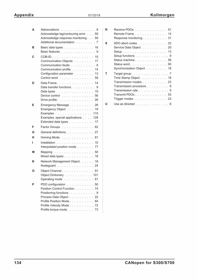
134 CANopen for S300/S700
Appendix 07/2016 Kollmorgen
A Abbreviations . . . . . . . . . . . . . . 8
Acknowledge lag/contouring error . . . 59
Acknowledge response monitoring . . . 59
Additional documentation . . . . . . . . 7
B Basic data types . . . . . . . . . . . . 16
Basic features . . . . . . . . . . . . . . 9
C COB-ID . . . . . . . . . . . . . . . . . 15
Communication Objects . . . . . . . . 17
Communication faults . . . . . . . . . . 9
Communication profile . . . . . . . . . 14
Configuration parameter . . . . . . . . 13
Control word . . . . . . . . . . . . . . 58
D Data Frame . . . . . . . . . . . . . . . 14
Data transfer functions . . . . . . . . . . 9
Data types . . . . . . . . . . . . . . . 15
Device control . . . . . . . . . . . . . 56
Drive profile. . . . . . . . . . . . . . . 26
E Emergency Message . . . . . . . . . . 26
Emergency Object . . . . . . . . . . . 18
Examples . . . . . . . . . . . . . . . 115
Examples, special applications . . . . 128
Extended data types . . . . . . . . . . 17
F Factor Groups . . . . . . . . . . . . . 62
G General definitions . . . . . . . . . . . 27
H Homing Mode. . . . . . . . . . . . . . 81
I Installation . . . . . . . . . . . . . . . 10
Interpolated position mode . . . . . . . 77
M Mapping . . . . . . . . . . . . . . . . 50
Mixed data types . . . . . . . . . . . . 16
N Network Management Object. . . . . . 18
Nodeguard . . . . . . . . . . . . . . . 24
O Object Channel . . . . . . . . . . . . . 91
Object Dictionary . . . . . . . . . . . 101
Operating mode . . . . . . . . . . . . 61
P PDO configuration . . . . . . . . . . . 50
Position Control Function . . . . . . . . 74
Positioning functions . . . . . . . . . . . 9
Process Data Object . . . . . . . . . . 22
Profile Position Mode . . . . . . . . . . 84
Profile Velocity Mode . . . . . . . . . . 72
Profile torque mode. . . . . . . . . . . 73
R Receive PDOs . . . . . . . . . . . . . 51
Remote Frame . . . . . . . . . . . . . 14
Response monitoring . . . . . . . . . . 31
S SDO abort codes . . . . . . . . . . . . 22
Service Data Object . . . . . . . . . . 20
Setup . . . . . . . . . . . . . . . . . . 13
Setup functions . . . . . . . . . . . . . 9
Status machine . . . . . . . . . . . . . 56
Status word . . . . . . . . . . . . . . . 60
Synchronization Object . . . . . . . . . 18
T Target group . . . . . . . . . . . . . . . 7
Time Stamp Object . . . . . . . . . . . 18
Transmission modes . . . . . . . . . . 23
Transmission procedure . . . . . . . . . 9
Transmission rate . . . . . . . . . . . . 9
Transmit PDOs . . . . . . . . . . . . . 53
Trigger modes . . . . . . . . . . . . . 23
U Use as directed . . . . . . . . . . . . . 8

This page has been deliberately left blank.
CANopen for S300/S700 135
Kollmorgen 07/2016 Appendix

Service
We are committed to quality customer service. In order to serve in the most effective way,
please contact your local sales representative for assistance.
If you are unaware of your local sales representative, please contact the Customer Support.
Europe
KOLLMORGEN
Internet www.kollmorgen.com/en-gb
E-Mail [email protected]
Tel.: +49 (0)2102 - 9394 - 0
Fax: +49 (0)2102 - 9394 - 3155
KOLLMORGEN European
EU Website Product WIKI
North America
KOLLMORGEN
Internet www.kollmorgen.com/en-us
E-Mail [email protected]
Tel.: +1 - 540 - 633 - 3545
Fax: +1 - 540 - 639 - 4162
KOLLMORGEN KOLLMORGEN
US Website Developer Network
South America
KOLLMORGEN
Internet www.kollmorgen.com/pt-br
E-Mail [email protected]
Tel.: +55 11 4191 - 4771
KOLLMORGEN
Brazil Website
Asia
KOLLMORGEN
Internet www.kollmorgen.cn
E-Mail [email protected]
Tel: +86 - 400 661 2802
KOLLMORGEN
CN Website