Embed Size (px)
Citation preview

Integration & Operation of
Canavie Technologies Android-based
CarPC Infotainment System
in a 2003 Toyota Land Cruiser (UZJ-100 with “Gen 03” NAV & integrated Climate controls)
prepared by member Watercruiser for IH8MUD Community
with assistance from members macmann & seanz0rz
…from this
to this…
in 9 hours
for ~$600
1 Rev. 0
1/10/17
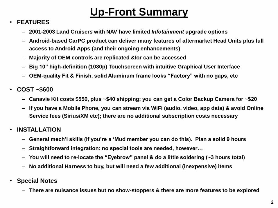
Up-Front Summary • FEATURES
– 2001-2003 Land Cruisers with NAV have limited Infotainment upgrade options
– Android-based CarPC product can deliver many features of aftermarket Head Units plus full
access to Android Apps (and their ongoing enhancements)
– Majority of OEM controls are replicated &/or can be accessed
– Big 10” high-definition (1080p) Touchscreen with intuitive Graphical User Interface
– OEM-quality Fit & Finish, solid Aluminum frame looks “Factory” with no gaps, etc
• COST ~$600
– Canavie Kit costs $550, plus ~$40 shipping; you can get a Color Backup Camera for ~$20
– If you have a Mobile Phone, you can stream via WiFi (audio, video, app data) & avoid Online
Service fees (Sirius/XM etc); there are no additional subscription costs necessary
• INSTALLATION
– General mech’l skills (if you’re a ‘Mud member you can do this). Plan a solid 9 hours
– Straightforward integration: no special tools are needed, however…
– You will need to re-locate the “Eyebrow” panel & do a little soldering (~3 hours total)
– No additional Harness to buy, but will need a few additional (inexpensive) items
• Special Notes
– There are nuisance issues but no show-stoppers & there are more features to be explored
2

Contents
Section 1 Background & Objective
Section 2 Operation
Section 3 Vehicle Integration
Section 4 Problems & Solutions (provisional)
Section 5 FAQs (provisional)
3

Section 1
Background & Objective
4

Background:
early UZJ-100 controls were Simpler
• Used [then conventional] “federated” architecture – Audio system was separate, had its own controls
– Climate Controls were completely independent
– “Steering Wheel controls” not yet mainstream
– No [need for a] Multi-Function Display
• “Infotainment” not widely available in NADM* – Smartphones, Bluetooth, NAV, OBDII etc. yet to be
provided in real-time to Occupants *Toyota was the first Automobile Manufacturer to introduce on-
board Navigation, starting with the Celica - JDM MY1981; also the first to provide a CD-ROM based system. just sayin
• Upgrade: replace “Stereo” with aftermarket Unit – Plug & Play (with correct aftermarket harness)
– Add Touchscreen, Voice-Control, Bluetooth-Smartphone (hands-free calling… audio streaming), better NAV, add A/V (in & out)… play DVD & stored media… add Backup Camera… Sirius/XM…
– Pioneer AVIC-series was one of the first, now there are others
5

Then things got Better… for awhile
• NADM Units saw integrated NAV/Climate starting in MY2001
– Wow! but as time passed this feature became outdated
– Display Unit can’t be upgraded or replaced (without serious hacking)
– Currently available upgrades offer some improvement
• VAISTech, GROM, etc. add Bluetooth integration (~$230)
• NavTool provides A/V inputs for Backup Camera (~$200+)
• GROM VLINE (2003-2005) offers Android-based Infotainment (~$500)
– While early NAV-equipped vehicles are somewhat rare…
…2001-2003 non-NAV equipped units are hard to find. NOW WHAT??
• OBJECTIVE: I want it ALL in my 2003
– Forum members @macmann & @sean0rz post initial Canavie experience. is this our Unicorn?
• big color Touchscreen for my tired eyes
• all the bells & whistles of an Aftermarket Head Unit (if others can have this, dammit so should I)
• access Steering Wheel & Climate controls (they’re still there, so they better work!)
• The EXPERIMENT: install Canavie Android-based CarPC
– testbed is a 2003 NAV-equipped (Gen-03) UZJ-100
– *might* apply to other MY NAV-equipped UZJ-100’s & LX-470’s
– Owners who have non-NAV equipped vehicles should consider
(the simpler) aftermarket Head Unit upgrade (see previous page)
6
2001 Land Cruiser w/NAV
Canavie 10” CarPC

Section 2
Operation Part A Functional Comparison Matrix
Part B OEM Operation Overview
Part C CarPC (Android) Operation Overview
7

Part A: Functional Comparison
8
OEM Mode CarPC Mode
MFD Button Functions Touchscreen Comments
MAP (VOICE)
DEST
MENU
DISPLAY
INFO OBDII App requires OBDII dongle ($20) but gives more info
OEM Mode CarPC Mode
Comments
via Touchscreen*requires going into OEM
mode
* all Climate functions are replicated via Touchscreen,
however on-screen temperature is shown in Celcius
Comments
AM (Touchscreen)
FM1/2/3 (Touchscreen)
TAPE
CD
Equalizer built-in App Stereo sounds much better in Android mode
Bluetooth enables hands-free calling & media streaming
AUX IN (A/V) I connected a Backup Camera to the VIDEO IN
VIDEO OUT 1
VIDEO OUT 2
DVR IN (video)
CCD IN (video)
Comments
VOLUME (Up, Down) Touchscreen
VOICE ACTIVATION yet to be tested possible to get OEM function back via GROM dongle
STEERING WHEEL Functions
MODE
haven't figured out how to make these all work just yet
available via User installed
Streaming App(s)
stored media
not an OEM function
although the iGO is pre-loaded
the User can install other NAV AppsiGO App
Android Settingsnative Settings functions allow User to customize
a larger variety of parameters
Time reset
Available with Eyebrow relocation
CLIMATE Functions
AUDIO Functions
Android Apps require Cellphone WiFi connection
User must upload media content via USB
SECURITY (flashing red LED)
OUTSIDE TEMP
[selected] TEMP
TIME (HH:MM:SS)
H set
M set
TEMP UP/DOWN
AUTO
DEFROST
CLIMATE
RECIRC
Functionality
No Change
Degraded
Not Accessible
Enhanced
New
haven't figured out yet

Part B: Operating Flow eyechart – OEM Controls all screenshots are from WaterCruisers’ 2003 UZJ-100
• System initializes to the OEM HOME screen… everything is controlled via Touchscreen input
• replicates most OEM functions & adds the App (Android CarPC) function
• missing are the OEM functions for [Cassette] Tape, NAV, Language, Maintenance, System Info, etc
• Touch one of the icons on the HOME screen to go to a sub-screen… touch to return HOME • The Traffic Info sub-screen actually displays Trip info (as opposed to Traffic conditions)
• DVD controls don’t work in my vehicle (I removed the DVD Player to make room for a Ham rig)
• A/C Settings (e.g. Climate) controls & Temp displays ALL WORK (although units are all Celsius, a little annoying)
• Sound Effect Settings are non-responsive (Equalizer, Balance & Fade don’t effect Radio & DVD audio output)
• Radio allows cycling through FM1, FM2 and AM; Station memory & Scanning functions work normally
Traffic Info DVD controls A/C Settings Sound Effect Settings
Radio controls
Apps (Android GUI)
Audio Settings
HOME screen
jumps to (currently useless) OEM
Sound Effects Settings
These touchscreen controls only
work in the (Android) Apps mode
these controls
still work
9

Part C: Operation of Android CarPC functions all screenshots are from WaterCruisers’ 2003 UZJ-100
touching Apps icon in HOME screen
takes you to the Android OS
Android “home” screen lets you
launch applications & widgets
you’ve installed via touchscreen
icons (many are pre-loaded);
home screen is customizable for
most-frequently-used Apps
$17 backup cam connected to
Canavie “Aux” video in
Android system settings
Weather Radar app
(downloaded right before
I took this picture)
audio
mute
OEM
HOME
previous
screen
increase
Volume
decrease
Volume
apps
overview
previous
screen
WiFi
active Pandora
is running
Return to
OEM HOME
there is an enormous variety of
Android Apps you can download
iGO
(NAV)
Tunein
(streaming
radio)
Video
player
GPS
diag.
Bluetooth
control
Audio
player
OBDII
monitor
access to pages of icons in your
“library” of installed Apps
Disclaimer Android functionality and
application use is beyond the
scope of this document
OEM audio (Radio & DVD) & their
controls go away in Android mode,
but are replaced with [far more
diverse] streaming A/V sources,
better equalizer control, HD-video
and improved audio output
... ...
10

Section 3
Vehicle Integration
Part D Canavie Parts Kit Description
Part E Preparing to perform the Installation
Part F OEM Display Unit Removal & Disassembly
Part G Canavie Display Hardware Integration
Part H Eyebrow Display & Control relocation
Part I Canavie Accessories & Wiring Installation
Part J Interior Re-assembly & Final Installation
Part K Verifying Operation and Adjusting Settings 11

Interface Module
Part D: Contents of the Canavie Kit
12
10” Display Module
Speaker/USB Harness
& Microphone
… and a ziplok baggie of
Small Screws
Accessory Harness
Interface Harness
Interface Module
CCA Enclosure
(2 metal shells) GPS & WiFi
Antenna

Part J:
Final Installation
Part H: OPTIONAL Eyebrow Relocation
Part I: Canavie Accessory Installation
Part G: Canavie Display Module Integration Part F: OEM Display Unit Disassembly
13
Remove Display
Unit from
Instrument Panel
Remove Circuit
Card Assy from
Display Module
Modify Kit-supplied
Metal Enclosure &
mount CCA
Extend
CCA
Harness
Assemble 10” Display
& CCA Enclosure to
OEM Display Chassis
mount Canavie
Speaker & Antennae
& route Cables
route & connect
Canavie Wires &
Interface Module
Part K:
Verify Operation,
Adjust Settings &
Customize
Partially
Disassemble
Display Unit
remove & trim Upper
(Shift) Console &
Center Bezel
Remove “Eyebrow”
& trim Window
Part E: Workflow Overview budget 9 hours* to do this
1 hour 3 hours
Mount Eyebrow
parts to Upper
Console
Finish Connections &
Re-mount Display Unit
to Instrument Panel
Install
Shifter Console
& Center Bezel
30-min
30-min 3 hours*
1 hour
* OPTIONAL STEPS the “Eyebrow” does NOT have
to be connected for the system
to work, but doing this will
provide some Climate control
in “Android mode” & shows
Time/Temp info all the time
OPTIONAL

Part E: Preparing for the Installation • Prepare a clean, covered work area
– suggest a large white cloth towel on a 6-ft work table
– nothing gets scratched & you won’t lose small items
• Tools you will need – Plastic Putty knife (thin, wide-blade or similar)
– Tape Measure
– Slotted Screwdriver (small blade)
– Phillips Head Screwdrivers (long #2, short #1)
– 1/4-in & 3/8-in Socket Drive & extensions
– 8mm & 10mm sockets (regular or deep)
– Portable Lighting; also, a small Flashlight
– Electric Drill, plus ¼” & 3/32” drill bits
– Tin Snips
– Metal File (medium-fine tooth)
– Scissors
– Small Saw
– Pliers
– Soldering Iron (Fine-tip)
– Wire Cutters
– Wire Stripper
– Wire Terminal Crimper
– Volt-Ohmmeter
– Sharpie Marker (Black, Fine-tip)
14
• Additional materials you will need – 2 sets of 1.5” #8-32 Machine Screws, Flat
Washers & Nuts
– 4 ea #6 x 3/4” Flat Head screws
– a roll of Black Electrical Tape
– Wire Labels (white electrical tape works)
– Cable Ties (medium)
– 3-inch length of ½-inch rubber tubing
– 2 inches of 3/8 dia. hard plastic tubing
– Ring- and Quick Disconnect Terminals
– Optional: Shrink Sleeve Tubing
– Optional: 40-ft of AWG18 stranded
insulated wire
• Budget Time (rough estimates)
– 8 hours for hardware remove & install
– 1 hour to adjust Android settings
• Patience & a clear game plan
READ THIS ENTIRE DOCUMENT & UNDERSTAND IT THOROUGHLY BEFORE BEGINNING
Disclaimer Author assumes no responsibility for damage or injuries resulting from these Procedures
User assumes full responsibility for outcome
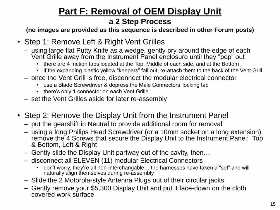
Part F: Removal of OEM Display Unit a 2 Step Process
(no images are provided as this sequence is described in other Forum posts)
• Step 1: Remove Left & Right Vent Grilles – using large flat Putty Knife as a wedge, gently pry around the edge of each
Vent Grille away from the Instrument Panel enclosure until they “pop” out • there are 4 friction tabs located at the Top, Middle of each side, and at the Bottom
• if the expanding plastic yellow “keepers” fall out, re-attach them to the back of the Vent Grill
– once the Vent Grill is free, disconnect the modular electrical connector • use a Blade Screwdriver & depress the Male Connectors’ locking tab
• there’s only 1 connector on each Vent Grille
– set the Vent Grilles aside for later re-assembly
• Step 2: Remove the Display Unit from the Instrument Panel – put the gearshift in Neutral to provide additional room for removal
– using a long Philips Head Screwdriver (or a 10mm socket on a long extension) remove the 4 Screws that secure the Display Unit to the Instrument Panel: Top & Bottom, Left & Right
– Gently slide the Display Unit partway out of the cavity, then…
– disconnect all ELEVEN (11) modular Electrical Connectors • don’t worry, they’re all non-interchangable… the harnesses have taken a “set” and will
naturally align themselves during re-assembly
– Slide the 2 Motorola-style Antenna Plugs out of their circular jacks
– Gently remove your $5,300 Display Unit and put it face-down on the cloth covered work surface
15

Part F: OEM Display Unit Partial-Disassembly
there are 2 Sequences
16
OEM Display Unit
assembly
after removal from
Instrument Panel
back side of
Display Unit
Sequence 1: partially disassemble the OEM Display Unit, removing
the Flat Panel Screen & the surrounding button fascia
and keeping the rest of the assembly for re-use
the OEM Display Module &
it’s button surround will be
removed & replaced with the
Canavie 10” Display…
… and the Audio
Control section
…will remove & re-use the Circuit
Card mounted in the back of the
OEM Display Module (shown with
the 4 connectors at the top)…
…this Black Plastic
Enclosure & the
OEM Chassis…
…the “Eyebrow”
Display…

Part F, Sequence 1
Display Unit Disassembly (cont.)
17
1.a with the Display-side down,
remove the Screws from the 4
circled locations from right Bracket;
take note of the 2 different types of
Screws for later re-assembly
1.b here’s the other
(left/Drivers) side showing
these 4 Screw removal
locations. Total of 8 Screws
will be removed
2. now temporarily lift out the
Black Plastic CCA enclosure
(it will be re-used). There are
no electrical connectors to
deal with here
3. next, remove the 3 Screws that
secure the bottom of the Display
Module to the top of the black plastic
Audio/HVAC Controls module
5. now separate the Display
Module from the chassis
in Sequence 2 (next page) we will remove the Circuit
Card from the Display Modules’ metal enclosure
4. next, flip the Display
Module on its end so you can
remove this last little Screw
the Circuit Card
we need is in here

Part F, Sequence 2
Harvesting the Display Module CCA
18
6. with the bare Display Module
screen-side down, remove the
small Screws from the 4 circled
locations
7. now lift off the Cover to reveal
the Circuit Card (note: this was after
I’d covered & taped the Cable
bundle to protect it)
8.a now remove the 4 small Screws in the circled locations...
8.b ...gently pull out the 2 Flat Tape connections…
8.c …and CAREFULLY unplug the 3 white Plastic connectors
8.d then place the CCA on a soft cloth
3 White Plastic
Connectors
2 Flat Tape
connectors
[slide out the
locking cover
so the ribbon
can pull out]
in Sequence 3 we
will install the
Display Module
Circuit Card into a
Metal Enclosure
(next page)
Front (right)
& Rear (below) of
Display Module CCA
ready for re-use
!!! CAUTION !!! Handle CCA only by edges &
avoid exposure & contact with
anything electrical
9. finally: bend in half
these last 2 copper
grounding fingers
note: these 4 Connectors
are important for Step 10
(on the next page)

Part G: Enclosing the CCA my Kits’ Enclosure needed to be modified to mount the CCA… check yours first
(the CCA fit within the Enclosure, but 2 Standoffs were in the wrong locations & the Connector “opening” wasn’t big enough)
19
10.a if needed, use Tin Snips to open
up the “window” in the Cover so that
after the CCA is mounted, its 4 White
Modular connectors are not blocked (this
will ensure proper engagement of the
Male connectors)
10.b also trim a U-shaped opening so
that the Cable bundle can exit. File all
edges smooth
10.c finally, slice down the length of a
short length of Rubber Vacuum hose &
wrap it around the U-shape (this to
protect the Cable from abrasion)
11.a using Pliers, twist/pull
out the 2 metal Standoff Posts
from the 2 circled locations
inside the Cover…
11.b …then drill a ¼”-hole in
the 2 circled area to align w/
corresponding CCA thru-holes
existing opening
in the Kit Cover
material removed to
accommodate CCA
connector mating
Enclosure Cover
(supplied in Canavie Kit)
Rubber tubing
wrapped around
rough edge
12.a time to make 2 Standoffs: I
cut 2-pcs of hard plastic Tubing
the same length as the Posts
removed in Step 11.a
12.b then I got two #8-32UNF
Screws, Nuts & Flat Washers
13.a mount the CCA to the
Cover using 2 short Screws
(supplied) & the 2 longer
Screws with their standoffs &
Nuts. The CCA Connectors
should face the opening that
you enlarged in Step 10.a
13.b now assemble the
other half of the Enclosure
& secure with 4 small
Screws (supplied in the Kit)
I left these 2
Standoffs alone
Nut Hard Plastic
tubing Machine Screw
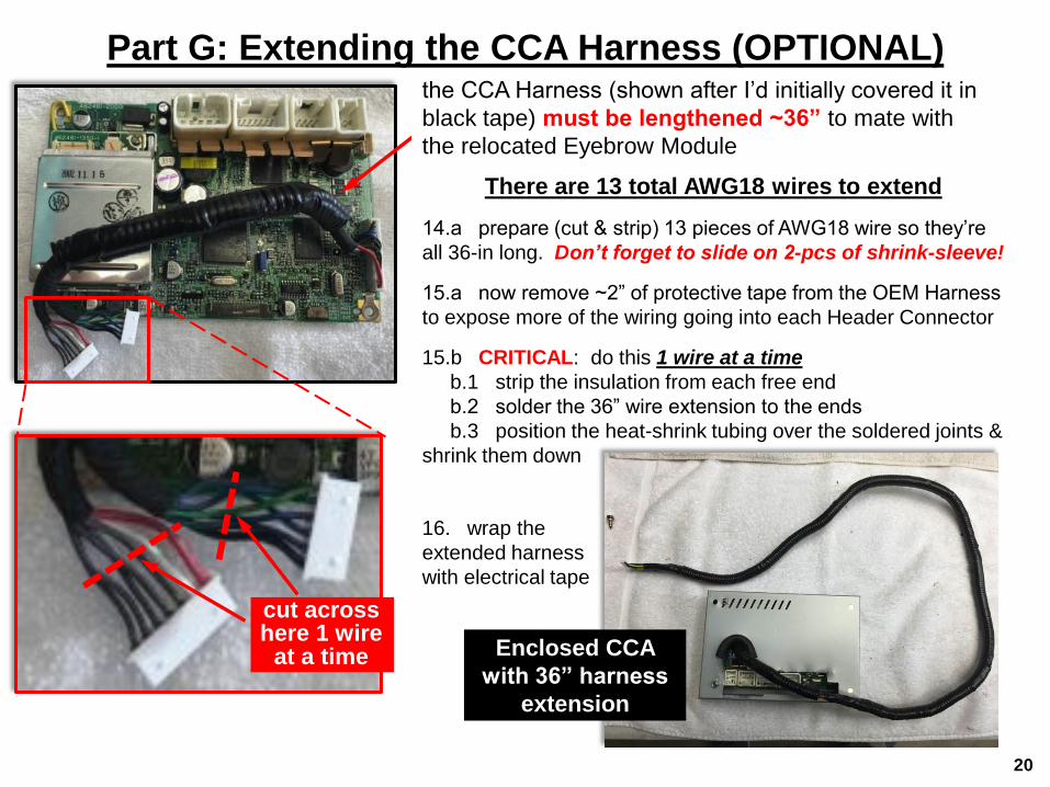
Part G: Extending the CCA Harness (OPTIONAL)
20
the CCA Harness (shown after I’d initially covered it in
black tape) must be lengthened ~36” to mate with
the relocated Eyebrow Module
There are 13 total AWG18 wires to extend
14.a prepare (cut & strip) 13 pieces of AWG18 wire so they’re
all 36-in long. Don’t forget to slide on 2-pcs of shrink-sleeve!
15.a now remove ~2” of protective tape from the OEM Harness
to expose more of the wiring going into each Header Connector
15.b CRITICAL: do this 1 wire at a time
b.1 strip the insulation from each free end
b.2 solder the 36” wire extension to the ends
b.3 position the heat-shrink tubing over the soldered joints &
shrink them down
cut across here 1 wire
at a time
16. wrap the
extended harness
with electrical tape
Enclosed CCA
with 36” harness
extension

21
Part G: Re-assembling the Display Unit
17.a checking how the
10” Canavie Screen fits
above the lower Bezel 18.a with the Screen display-side down, position the Screen 2 upper mounting tabs
between the Display chassis Brackets
18.b secure the Screens left & right mounting tabs to the (black plastic) HVAC/Audio
Control module with 2 Screws (which you removed in Step 3) at the circled locations
upper mounting tabs upper tabs slide in-between brackets
19. now insert the CCA
Enclosure (from Step 16)
between the Brackets
20. then insert the
Plastic Enclosure
(from Step 2)
21.a the finished assembly
should all nest together;
the extended Eyebrow
Harness should be routed
to not interfere or block the
4 Connectors
21.b now secure both
Enclosures to the Brackets
(reverse of Step 1.b); the 2
machine screws will clamp
the CCA Enclosure in place
Left Mounting Tab
Right Mounting Tab
Screw position
ensure these 4 female Connectors
are not blocked

Part H: “Eyebrow” Relocation (1 of 2) Optional but recommended: retains direct access to Climate functions
22
22.a remember this? flip it over
22.c now grind away all the small plastic welds that
secure the plastic “Window” to the back of the Bezel
now you have these 2 parts
Eyebrow Display CCA
Clear Plastic Window
22.b remove the small Screws from the 3 circled
locations & pull the CCA free from the Bezel

25. … and insert the Window. Secure
with adhesive & fill gaps; touchup gaps
w/black ink
Part H: “Eyebrow” Relocation (2 of 2) Optional but recommended: retains direct access to Climate functions
23
24. now grind the
Window until it just barely
fits in the lower opening
you just cut in the Shifter
Console…
23.a using the Eyebrow
Faceplate as a guide,
prepare a trimming
Template from cardstock to
determine where the
Buttons & Window
openings should be…
23.b tape the Template to
the Console…
23.c …and trim away the
plastic. You can do much
better than I did!
(hint: if I could do this
again I would move the
template 3/8” further down)
trimmed Plastic Window
installed in the cutout
26.a insert the Eyebrow CCA in it’s new location…
26.b … and drill 4 small c’sunk holes through the Shifter Console so they align with the CCA’s mounting holes (circled)
26.c then secure the Eyebrow to the Console with 4 Flathead Screws, nuts & washers
That was all very stressful.
time for a drink 4 Flathead Screws/Nuts/Washers secure
the Eyebrow to the Shifter Console
partway through
trimming operation
Eyebrow buttons will
protrude here
Eyebrow display window
slots for Hour, Minute &
Reset buttons
hole for Anti-Theft red LED
mounting through-holes in
Eyebrow CCA Module
24
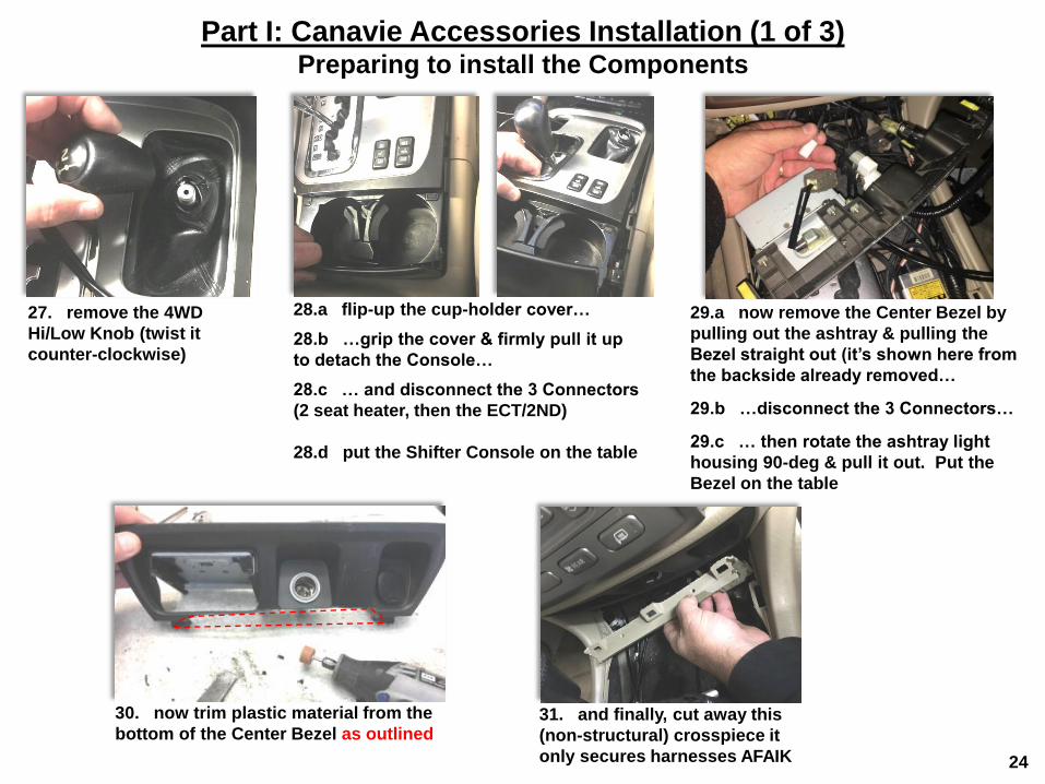
Part I: Canavie Accessories Installation (1 of 3) Preparing to install the Components
27. remove the 4WD
Hi/Low Knob (twist it
counter-clockwise)
28.a flip-up the cup-holder cover…
28.b …grip the cover & firmly pull it up
to detach the Console…
28.c … and disconnect the 3 Connectors
(2 seat heater, then the ECT/2ND)
28.d put the Shifter Console on the table
29.a now remove the Center Bezel by
pulling out the ashtray & pulling the
Bezel straight out (it’s shown here from
the backside already removed…
29.b …disconnect the 3 Connectors…
29.c … then rotate the ashtray light
housing 90-deg & pull it out. Put the
Bezel on the table
30. now trim plastic material from the
bottom of the Center Bezel as outlined 31. and finally, cut away this
(non-structural) crosspiece it
only secures harnesses AFAIK

Interface Module
25
10” Display Module
Speaker/USB Harness Accessory
Harness
Interface Harness
GPS & WiFi Antennae
Part I: Canavie Components Installation (2 of 3) Component features & connection details
GPS Antenna In WiFi Antenna In
receptacle “A”:
receives Accessory
Harness connector
receptacle “B”:
receives Accessory
Harness connector
plugs into
Interface Module
receptacle “D”
plugs into OEM Display
receptacle 1
re-assembled Display Unit
OEM Display receptacle 1
(receives Interface
Harness connector)
receives male
OEM Instrument
Panel connector
3.5mm Stereo IN
(from Accessory
Harness)
receptacle “C”:
receives Accessory
Harness connector
receptacle “D”:
receives Interface
Harness connector
Plugs into Canavie
Display “B” receptacle
Plugs into
Interface Module
receptacle “C”
plugs into Display
Module receptacle A” Canavie Speaker
(routes down to Console)
USB Connector #2
(routes down to Console)
USB Connector #1
(routes down to Console) 3.5mm Stereo OUT
(to Interface Module)
GPS Patch
Antenna
WiFi Antenna
connect to the Antenna
inputs on the top of the
Canavie Display Module
GPS Antenna In WiFi Antenna In
front rear top
route all these
connectors &
pigtail wires down
to the Console

Part I: Component Installation & Wire Routing (3 of 3) (refer to Part D for Part Identification)
GPS & WiFi antennae
sit in corner next to
A-Pillar
Microphone [in front of Cluster]
GPS Antenna
WiFi antenna
“A” & “B” Connectors
Interface Module (left of Vent)
Connections at
top of Display unit
Interface Cable connects
to this position
GPS & WiFi antenna
cables route behind
door seal & glovebox Microphone cable
routing (plugs into
Accessory Harness)
3.5mm Stereo
Plug (from
Accessory
Harness)
Accessory Harness
“A” Connector
Cables from Accessory &
Speaker/USB Harnesses
route down from top of
Display Module
don’t forget to plug in the
OEM AM & FM Motorola
antenna plugs
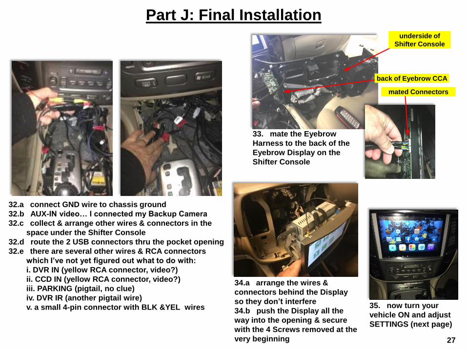
Part J: Final Installation
27
32.a connect GND wire to chassis ground
32.b AUX-IN video… I connected my Backup Camera
32.c collect & arrange other wires & connectors in the
space under the Shifter Console
32.d route the 2 USB connectors thru the pocket opening
32.e there are several other wires & RCA connectors
which I’ve not yet figured out what to do with:
i. DVR IN (yellow RCA connector, video?)
ii. CCD IN (yellow RCA connector, video?)
iii. PARKING (pigtail, no clue)
iv. DVR IR (another pigtail wire)
v. a small 4-pin connector with BLK &YEL wires
33. mate the Eyebrow
Harness to the back of the
Eyebrow Display on the
Shifter Console
underside of
Shifter Console
back of Eyebrow CCA
mated Connectors
34.a arrange the wires &
connectors behind the Display
so they don’t interfere
34.b push the Display all the
way into the opening & secure
with the 4 Screws removed at the
very beginning
35. now turn your
vehicle ON and adjust
SETTINGS (next page)

Part K: Adjusting System Settings
28
After startup you will see this HOME screen Audio Settings screen
36.a touch the “Audio Settings” icon to open the
“Audio Settings” screen…
36.b …then configure as follows:
- touch Audio Exchange to “Auto”
- touch “Logo” box to get “1” (“2” will show a Lexus
icon at startup)
- touch the “LC100” box
That’s it - you’re DONE!
Go enjoy a homebrew

Section 4
Problems & Solutions
(provisional)
29

Section 5
FAQs
(provisional)
30

Equipment Info
• Aftermarket Item
– Mfr: Shenzen Canavie Technoloy Co., Ltd.
– Model: R16 Toyota Land Cruiser 100 LC100
– http://www.canaviet.com/e_productshow/?317
-android-car-multimedia-head-unit-autoradio-
headunit-car-stereo-gps-toyota-land-cruiser-
100-lc100-317.html
31